specifi cation guide - just insulation · bs 476 part 7:1997 ... 8 floors specifi cation guide...
TRANSCRIPT
1
FloorsSpecifi cation Guide
CI/SfB (2-) Rn7 (M2)

2 Floors Specifi cation Guide
Contents
222222222222222222222222 FloFFloFloFloloFloFFlooFlFFloF oorsorsoorsorsorsrsororsoorrr SpSpSSSpSpSpSppppSppppSpppppppppppppppppppppppppSppppppppSppppppSppppppppppppppppppppppppppppeecicicciciicicieecieeeecceeeeeeeeeeeeeeeeeeeeeceeeecceeeeceeeeececceeeeeceeceececeeeccc ficficficfi cfificfi ccccccccfifi ccfi fi fificcatiatiatiatiatiatiiatiiiataatit ononoon on on on onooo GuiGuiGuiGuiGuGuGuGuGuiGuiGGuiGuiGuidedededededdedeeeeeeeeeeee
Introduction 3
Product Properties 4
Certifi cation 6
Sustainability 7
Specifi cation Support 8
Building Regulations 9
U-value Tables 10
Design Considerations and Installation Guidelines 13
General Information 19
Hepworth Gallery, Wakefi eld

3
Introduction
Increasingly, thermal performance has become a critical element of modern fl oor design as specifi ers strive to minimise downward heat loss in dwellings. In order to meet the demands of current Building Regulations, designers must address the key issues of thermal transmittance, thermal bridging and thermal mass. These must be addressed in a way that is sympathetic and compliments the traditional design goals of fl oors; structural performance, resistance to the passage of sound and resistance to moisture. Celotex FR5000 is a premium performance PIR insulation solution featuring a super low lambda value of 0.021 W/mK ensuring Regulation compliance can be achieved with minimal insulation thickness. FR5000 closed cell formulation offers excellent resistance to moisture and has a high compressive strength making it the ideal solution for a range of fl ooring applications.
Celotex FF4000 is a specialist fl ooring product targeted at under screed applications including underfl oor heating systems. Featuring an enhanced compressive strength value of ≥150 kPa and a thermal conductivity value of 0.022 W/mK, FF4000 provides greater resistance to site traffi c and better clip retention for underfl oor pipe installations.
Increasingly, thermal performance has become a critical element of modern fl oor design as specifi ers strive to minimise downward heat loss in dwellings.

4 Floors Specifi cation Guide
Product Properties
Celotex FR5000
Celotex FR5000 is a multi-purpose insulation board with a rigid polyisocyanurate foam core adhesively bonded in the manufacturing process to super low emissivity aluminium foil facings on both sides.
Dimensions: 1200mm x 2400mm
Thickness Range: 25mm – 150mm
Compressive Strength: ≥120 kPa BS EN 826:1996 (Thermal insulating products for building applications – determination of compressive behaviour)
Dimensional Stability: DS (TH) 8 BS EN 1604:2013 (Thermal insulating products for building applications – determination of dimensional stability under specifi ed temperature and humidity conditions)
Thermal Performance: Celotex FR5000 has a declared thermal conductivity (λ-value) of 0.021 W/mK in accordance with BS EN 13165:2008 (Thermal insulation for products – factory made rigid polyurethane foam (PUR) products).
Celotex FF4000
Celotex FF4000 is a high performance insulation board comprising a rigid polyisocyanurate foam core with low emissivity aluminium foil facings on both sides for use in underfl oor heating systems.
Dimensions: 1200mm x 2400mm
Thickness Range: 50mm – 125mm
Compressive Strength: ≥150 kPaBS EN 826:1996 (Thermal insulating products for building applications – determination of compressive behaviour)
Dimensional Stability: DS (TH) 8BS EN 1604:2013 (Thermal insulating products for building applications – determination of dimensional stability under specifi ed temperature and humidity conditions)
Thermal Performance: Celotex FF4000 has a declared thermal conductivity (λ-value) of 0.022 W/mK in accordance with BS EN 13165:2008 (Thermal insulation for products – factory made rigid polyurethane foam (PUR) products).
Floor Insulation
Celotex FR5000 Technical Data
Underfl oor Heating
Celotex FF4000 Technical Data
Product Code
Thickness (mm)
R-value (m2K/W)
Weight (kg/m2)
FR5025 25 1.15 1.01
FR5040 40 1.90 1.49
FR5050 50 2.35 1.81
FR5060 60 2.85 2.16
FR5070 70 3.30 2.48
FR5075 75 3.55 2.64
FR5080 80 3.80 2.80
FR5090 90 4.25 3.12
FR5100 100 4.75 3.38
FR5120 120 5.70 4.02
FR5150 150 7.10 4.98
Product Code
Thickness (mm)
R-value (m2K/W)
Weight (kg/m2)
FF4050 50 2.25 1.98
FF4070 70 3.15 2.68
FF4075 75 3.40 2.86
FF4085 85 3.85 3.21
FF4090 90 4.05 3.38
FF4100 100 4.50 3.73
FF4125 120 5.65 4.61

5
Fire Performance
Floor Insulation
Celotex FR5000 is Class O fi re rated as described by the national Building Regulations having achieved:
▶ A pass to BS 476 Part 6:1989 (Fire tests on building materials and structures – method of test for fi re propagation for products).
▶ Classifi cation as Class 1 in accordance BS 476 Part 7:1997 (fi re tests on building materials and structures – method of test to determine the classifi cation of the surface spread of fl ame of products).
Underfl oor Heating Insulation
Celotex FF4000 is classifi ed as Class 1 in accordance with:
▶ BS 476 Part 7:1997 (fi re tests on building materials and structures – method of test to determine the classifi cation of the surface spread of fl ame of products).
Celotex FR5000 is faced with super low emissivity aluminium foil facings on both sides
Celotex IQ Emissivity
Celotex FR5000 is faced with super low emissivity aluminum foil facings on both sides. The highly refl ective foil facings deliver better U-values in constructions by enhancing the thermal resistance of the unventilated cavity air space adjacent to the board.
Willowfi eld, West Midlands

6 Floors Specifi cation Guide
Certifi cation
Third party approvals play a key role in distinguishing product performance between different manufacturers. To eradicate the perception that all PIR is the same, we recognise the importance of approvals and certifi cations from a number of leading organisations, including BBA, BRE, Ofgem and ISO. These approvals include independent validation of thermal, fi re and other product standards.
Product Code Application BBA No. ISO 9001 ISO 14001
FR5000 Floors 95/3197
FF4000 Underfl oor Heating 95/3197
The Co-operative Society, St. Helier

7
Sustainability
Suitable for use within a number of applications within the building fabric, the specifi cation of Celotex products will signifi cantly contribute to improving the energy effi ciency of the UK’s building stock.
Celotex is also able to independently certify the environmental impact for a selection of its product ranges. This includes Celotex FR5000.
Measured by its BRE Ecopoint score, Celotex achieve the lowest environmental impact of any PIR manufacturer and from its most recent recertifi cation, has improved this score by over 5% since 2010. Moreover, when compared to the generic PIR Ecopoint value, Celotex’ impact
is over 20% better than that of non-certifi ed PIR manufacturers.
Through its BRE Approved Environmental Profi le, Celotex was the fi rst PIR manufacturer to achieve an A+ Green Guide rating. This rating has been maintained through ongoing recertifi cation and now includes even more Celotex products as part of the profi le.
Celotex products are all manufactured in accordance with environmental management system ISO 14001. As well as this, the suppliers of the principal raw materials used in the manufacture of Celotex products also possess this standard allowing a credit to be achieved within the Materials category of BREEAM assessments.
Celotex manufacture solutions that start saving energy as soon as they are installed. Over its useful life, PIR insulation saves over 100 times more energy than was used in its manufacture.
Floor Insulation
Name of Insulation Material FR5000
Manufacturer Celotex
Unfoamed, Foamed or Installed using Propellants Foamed
Global Warming Potential (GWP) Less than 5
Blowing Agent Pentane
Green Guide Rating A+
Element Number 1315320025
Environmental Management System (EMS) - Key Process ISO 14001
Environmental Management System (EMS) - Supply Chain Process
ISO 14001
Underfl oor Heating Insulation
Name of Insulation Material FF4000
Manufacturer Celotex
Unfoamed, Foamed or Installed using Propellants Foamed
Global Warming Potential (GWP) Less than 5
Blowing Agent Pentane
Green Guide Rating A
Element Number 815320017
Environmental Management System (EMS) - Key Process ISO 14001
Environmental Management System (EMS) - Supply Chain Process
ISO 14001
For further information please see Celotex’ Sustainability Guide available at celotex.co.uk

8 Floors Specifi cation Guide
Specifi cation Support
Specifi cation Clause
Celotex FR5000
The fl oor insulation shall be Celotex FR5000 ________mm thick, comprising a polyisocyanurate (PIR) rigid foam insulation core featuring Celotex IQ providing super low emissivity textured aluminium foil facings on both sides and Class O fi re performance throughout the product in accordance with BS 476. FR5000 is A+ rated when compared to the BRE Green Guide, is CFC/HCFC free with low GWP and zero ODP and acheives CE marking compliance to BS EN 13165. FR5000 is manufactured in accordance with quality management systems ISO 9001 and environmental management system ISO 14001. All products must be installed in accordance with instructions issued by Celotex.
Celotex FF4000
The underfl oor heating insulation shall be Celotex FF4000 _____mm thick comprising a polyisocyanurate rigid foam insulation core with a thermal conductivity of 0.022 W/mK with low emissivity aluminium foil facings on both sides. Celotex FF4000 is CFC/HCFC free with zero ODP and low GWP and achieves CE marking compliance to BS EN 13165. Celotex FF4000 is manufactured in accordance with quality management system ISO 9001 and environmental management system ISO 14001. All products must be installed in accordance with instructions issued by Celotex.
Building Information Modelling (BIM)
Celotex FR5000 and FF4000 are available for BIM in the following software formats:
▶ Autodesk Revit▶ ArchiCAD▶ Vectorworks▶ Bentley▶ Industry Foundation Classes
(IFC)
Celotex products are available for BIM through both celotex.co.uk/bim and the NBS National BIM Library.
NBS Specifi cations
Celotex FR5000 and FF4000 are referenced in the following NBS clauses:
▶ M10 40▶ M10 290▶ M10 260
Technical Services
Celotex provide outstanding levels of technical expertise and personal assistance through two industry leading services:
Celotex Technical Centre
When it comes to fi nding easy-to-understand, quick and helpful advice regarding PIR insulation, the Celotex Technical Centre (CTC) is where you will discover high levels of support and guidance on fi nding the most appropriate solutions to meet your requirements. This includes provision of:
▶ U-value calculations ▶ Condensation risk analysis▶ Application and installation advice ▶ Guidance on compliance to Building
Regulations ▶ Information on our product and
environmental credentials
Call the Celotex Technical Centre on 01473 820850 to speak to one of our advisors, or alternatively email [email protected]
Celotex Energy Assessments
Offering energy calculations including SAP, SBEM and bespoke thermal modelling as well as additional services for pre-tender planning and sustainability assessments for the Code for Sustainable Homes and BREEAM.
For more information on Celotex Energy Assessments (CEA) please take a look at the CEA brochure on celotex.co.uk with a full breakdown of the services we can provide for your project requirements. For more information please phone 0333 733 0850 or email [email protected]
For more information on how to download Celotex FR5000 and FF4000 for BIM, visit celotex.co.uk/bim
Energy Assessments
Customers should be aware that Celotex and Darren Evans Assessments are separate legal entities and Celotex makes no warranty as to the quality of the services that DEA provides and assumes no responsibility in connection with those services. Customers should also be aware that, as an Assured Partner of Celotex, Darren Evans Assessments operate under a commercial agreement with Celotex for services provided by Darren Evans Assessments under the Celotex Energy Assessment Service.

9
Building Regulations
*Value required when extensions for houses have a reasonable standard of insulation
England Part L 2013
Scotland Section 6 2010
New Build Existing Buildings
Domestic Notional Value/Backstop
Non-Domestic Notional value/Backstop
New Thermal Element e.g. Extensions
Existing Thermal Element e.g. Garage Conversions
Walls 0.18 / 0.30 0.26 / 0.35 0.28 0.30
Floors 0.13 / 0.25 0.22 / 0.25 0.22 0.25
Pitched Roofs 0.13 / 0.20 0.18 / 0.25 0.18 0.18
Flat Roofs 0.13 / 0.20 0.18 / 0.25 0.18 0.18
New Build Existing Buildings
Domestic Notional Value/Backstop
Non-Domestic Notional Value/Backstop
New Thermal Element e.g. Extensions
Existing Thermal Element e.g. Garage Conversions
Walls 0.19 / 0.25 0.26 / 0.27 0.19* / 0.22* 0.30
Floors 0.15 / 0.20 0.22 / 0.22 0.18* / 0.18* 0.25
Pitched Roofs 0.13 / 0.18 0.18 / 0.20 0.18* / 0.18* 0.25
Flat Roofs 0.13 / 0.18 0.18 / 0.20 0.18* / 0.18* 0.25
Part L is an Approved Document within the Building Regulations for England dealing with the Conservation of Fuel and Power. It ensures that the design and construction of new buildings, as well as work done on existing buildings, meets targets designed to limit the associated CO2 emissions from the building following its construction or modifi cation. Below is a guidance table of U-values to help comply with Part L 2013 Building Regulations.
Section 6 of the Scottish Building Regulations is the Technical Handbook that deals with Energy within the built environment. Section 6 supports the Climate Change (Scotland) Act 2009 as it seeks to meet the target of an 80% reduction in carbon emissions by 2050 by ensuring that effective measures for the conservation of fuel and power are taken with constructing new or modifying existing buildings. Below is a guidance table of U-values to help comply with Section 6 2010 Building Regulations.

10 Floors Specifi cation Guide
U-valueTables
U-value calculations: fl oors over a vacant space using Celotex FR5000
U-value calculations: ground fl oors using Celotex FR5000
Suspended beam and blockFR5000 over beam and block under 65mm screed
Product Code U-value
FR5075 -
FR5080 -
FR5090 0.24
FR5100 0.23
FR5120 0.20
FR5150 0.19
Product Code U-value
FR5075 -
FR5080 -
FR5090 0.23
FR5100 0.21
FR5120 0.18
FR5150 0.14
Product Code U-value
FR5075 -
FR5080 0.24
FR5090 0.22
FR5100 0.20
FR5120 0.17
FR5150 0.13
Timber fl oor over a vacant space FR5000 bridged between 150mm timber joists at 400 ctrs. 22mm Chipboard fl oor fi nish and 2x12.5mm plasterboard fi nish
Concrete soffi t - exposed FR5000 to underside of 150mm concrete slab.
Concrete fl oor over a vacant space FR5000 above a concrete slab with 65mm screed
Product Code 0.1 0.2 0.3 0.4 0.5 0.6 0.7 0.8 0.9 1.0
FR5050 0.16 0.21 0.24 0.25 0.26 0.27 0.28 0.28 0.29 0.29
FR5060 0.15 0.19 0.21 0.23 0.24 0.24 0.25 0.25 0.25 0.26
FR5070 0.14 0.18 0.19 0.20 0.21 0.22 0.22 0.22 0.23 0.23
FR5075 0.14 0.17 0.18 0.19 0.20 0.21 0.21 0.21 0.21 0.22
FR5080 0.13 0.16 0.18 0.19 0.19 0.20 0.20 0.20 0.20 0.21
FR5090 0.12 0.15 0.16 0.17 0.18 0.18 0.18 0.18 0.19 0.19
FR5100 0.12 0.14 0.15 0.16 0.16 0.17 0.17 0.17 0.17 0.17
FR5120 0.11 0.12 0.13 0.14 0.14 0.14 0.14 0.15 0.15 0.15
FR5150 0.09 0.11 0.11 0.11 0.12 0.12 0.12 0.12 0.12 0.12
Perimeter / Area Ratio

11
Suspended timber fl oorFR5000 bridged between 150mm timber joists @ 400 ctrs
Ground bearing slab-insulation under slabFR5000 under 100mm concrete slab
Product Code 0.1 0.2 0.3 0.4 0.5 0.6 0.7 0.8 0.9 1.0
FR5070 0.16 0.21 0.24 0.26 0.27 0.28 0.29 0.29 0.30 0.30
FR5075 0.16 0.21 0.23 0.25 0.26 0.27 0.27 0.28 0.28 0.29
FR5080 0.16 0.20 0.22 0.24 0.25 0.26 0.26 0.27 0.27 0.28
FR5090 0.15 0.19 0.21 0.22 0.23 0.24 0.24 0.25 0.25 0.25
FR5100 0.14 0.18 0.20 0.21 0.22 0.22 0.23 0.23 0.23 0.24
FR5120 0.13 0.16 0.18 0.19 0.19 0.20 0.20 0.20 0.20 0.21
FR5150 0.12 0.14 0.15 0.16 0.16 0.17 0.17 0.17 0.17 0.17
Product Code 0.1 0.2 0.3 0.4 0.5 0.6 0.7 0.8 0.9 1.0
FR5050 0.12 0.18 0.21 0.23 0.24 0.26 0.27 0.27 0.28 0.28
FR5060 0.12 0.16 0.19 0.20 0.22 0.23 0.24 0.24 0.25 0.25
FR5070 0.11 0.15 0.17 0.19 0.20 0.21 0.21 0.22 0.22 0.22
FR5075 0.11 0.15 0.17 0.18 0.19 0.20 0.20 0.21 0.21 0.21
FR5080 0.10 0.14 0.16 0.17 0.18 0.19 0.19 0.20 0.20 0.20
FR5090 0.10 0.13 0.15 0.16 0.17 0.17 0.18 0.18 0.18 0.18
FR5100 0.09 0.12 0.14 0.15 0.15 0.16 0.16 0.17 0.17 0.17
FR5120 0.09 0.11 0.12 0.13 0.13 0.14 0.14 0.14 0.14 0.15
FR5150 0.08 0.09 0.10 0.11 0.11 0.12 0.12 0.12 0.12 0.12
Perimeter / Area Ratio
Perimeter / Area Ratio
12 Floors Specifi cation Guide
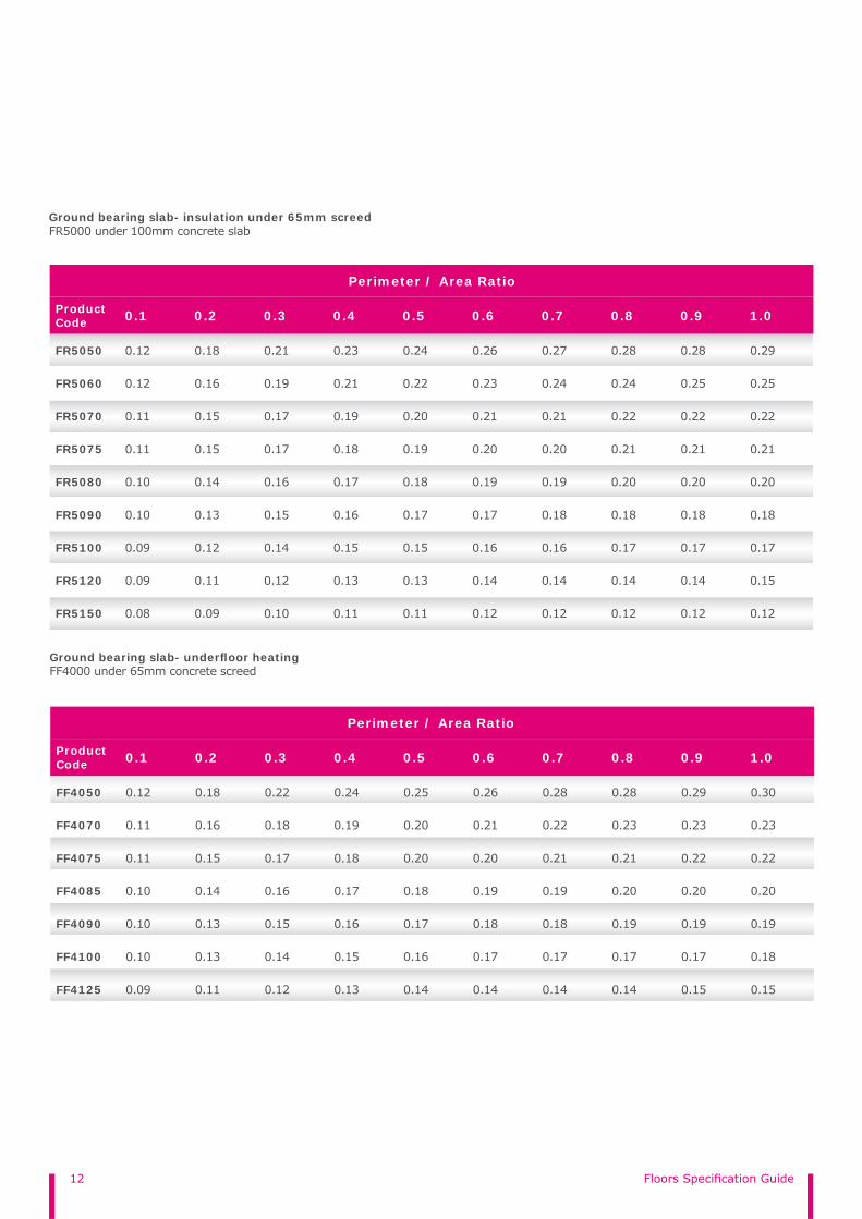
Ground bearing slab- underfl oor heating FF4000 under 65mm concrete screed
Product Code 0.1 0.2 0.3 0.4 0.5 0.6 0.7 0.8 0.9 1.0
FF4050 0.12 0.18 0.22 0.24 0.25 0.26 0.28 0.28 0.29 0.30
FF4070 0.11 0.16 0.18 0.19 0.20 0.21 0.22 0.23 0.23 0.23
FF4075 0.11 0.15 0.17 0.18 0.20 0.20 0.21 0.21 0.22 0.22
FF4085 0.10 0.14 0.16 0.17 0.18 0.19 0.19 0.20 0.20 0.20
FF4090 0.10 0.13 0.15 0.16 0.17 0.18 0.18 0.19 0.19 0.19
FF4100 0.10 0.13 0.14 0.15 0.16 0.17 0.17 0.17 0.17 0.18
FF4125 0.09 0.11 0.12 0.13 0.14 0.14 0.14 0.14 0.15 0.15
Ground bearing slab- insulation under 65mm screedFR5000 under 100mm concrete slab
Product Code 0.1 0.2 0.3 0.4 0.5 0.6 0.7 0.8 0.9 1.0
FR5050 0.12 0.18 0.21 0.23 0.24 0.26 0.27 0.28 0.28 0.29
FR5060 0.12 0.16 0.19 0.21 0.22 0.23 0.24 0.24 0.25 0.25
FR5070 0.11 0.15 0.17 0.19 0.20 0.21 0.21 0.22 0.22 0.22
FR5075 0.11 0.15 0.17 0.18 0.19 0.20 0.20 0.21 0.21 0.21
FR5080 0.10 0.14 0.16 0.17 0.18 0.19 0.19 0.20 0.20 0.20
FR5090 0.10 0.13 0.15 0.16 0.17 0.17 0.18 0.18 0.18 0.18
FR5100 0.09 0.12 0.14 0.15 0.15 0.16 0.16 0.17 0.17 0.17
FR5120 0.09 0.11 0.12 0.13 0.13 0.14 0.14 0.14 0.14 0.15
FR5150 0.08 0.09 0.10 0.11 0.11 0.12 0.12 0.12 0.12 0.12
Perimeter / Area Ratio
Perimeter / Area Ratio
13
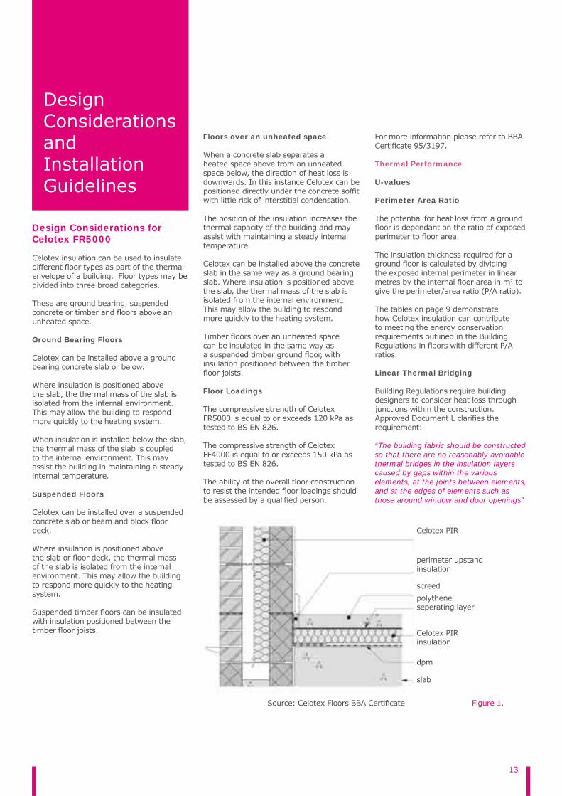
Source: Celotex Floors BBA Certifi cate
Design Considerations and Installation Guidelines
Design Considerations for Celotex FR5000
Celotex insulation can be used to insulate different fl oor types as part of the thermal envelope of a building. Floor types may be divided into three broad categories.
These are ground bearing, suspended concrete or timber and fl oors above an unheated space.
Ground Bearing Floors
Celotex can be installed above a ground bearing concrete slab or below.
Where insulation is positioned above the slab, the thermal mass of the slab is isolated from the internal environment. This may allow the building to respond more quickly to the heating system.
When insulation is installed below the slab, the thermal mass of the slab is coupled to the internal environment. This may assist the building in maintaining a steady internal temperature.
Suspended Floors
Celotex can be installed over a suspended concrete slab or beam and block fl oor deck.
Where insulation is positioned above the slab or fl oor deck, the thermal mass of the slab is isolated from the internal environment. This may allow the building to respond more quickly to the heating system.
Suspended timber fl oors can be insulated with insulation positioned between the timber fl oor joists.
Floors over an unheated space
When a concrete slab separates a heated space above from an unheated space below, the direction of heat loss is downwards. In this instance Celotex can be positioned directly under the concrete soffi t with little risk of interstitial condensation.
The position of the insulation increases the thermal capacity of the building and may assist with maintaining a steady internal temperature.
Celotex can be installed above the concrete slab in the same way as a ground bearing slab. Where insulation is positioned above the slab, the thermal mass of the slab is isolated from the internal environment. This may allow the building to respond more quickly to the heating system.
Timber fl oors over an unheated space can be insulated in the same way as a suspended timber ground fl oor, with insulation positioned between the timber fl oor joists.
Floor Loadings
The compressive strength of Celotex FR5000 is equal to or exceeds 120 kPa as tested to BS EN 826.
The compressive strength of Celotex FF4000 is equal to or exceeds 150 kPa as tested to BS EN 826.
The ability of the overall fl oor construction to resist the intended fl oor loadings should be assessed by a qualifi ed person.
For more information please refer to BBA Certifi cate 95/3197.
Thermal Performance
U-values
Perimeter Area Ratio
The potential for heat loss from a ground fl oor is dependant on the ratio of exposed perimeter to fl oor area.
The insulation thickness required for a ground fl oor is calculated by dividing the exposed internal perimeter in linear metres by the internal fl oor area in m2 to give the perimeter/area ratio (P/A ratio).
The tables on page 9 demonstrate how Celotex insulation can contribute to meeting the energy conservation requirements outlined in the Building Regulations in fl oors with different P/A ratios.
Linear Thermal Bridging
Building Regulations require building designers to consider heat loss through junctions within the construction. Approved Document L clarifi es the requirement:
“The building fabric should be constructed so that there are no reasonably avoidable thermal bridges in the insulation layers caused by gaps within the various elements, at the joints between elements, and at the edges of elements such as those around window and door openings”
Figure 1.
Celotex PIR
polytheneseperating layer
Celotex PIRinsulation
dpm
screed
slab
perimeter upstand insulation

14 Floors Specifi cation Guide
Similar performance standards are required in Scotland and Northern Ireland.
As insulation standards continue to evolve, is has become increasingly critical to consider heat loss in these areas. Accredited Construction Details (ACDs) for England & Wales, Scotland and Northern Ireland provide practical guidance on meeting this requirement. The documents provide approved design details for junctions within many common constructions, including ground fl oors.
Where work is being undertaken in an existing building – for example extensions, the requirement can be met by adopting the designs given in Accredited Construction Details. Where a new building is being constructed, heat loss through each junction is considered as part of the whole building carbon dioxide emissions calculation.
Using improved junction detailing will allow buildings to more easily meet the requirements of the Building Regulations. Heat loss through each junction is represented by the psi (ψ) value. Where ACDs have been adopted then a default ψ value may be used for each junction.
Junctions can also be individually modelled by a competent person and the ψ value calculated. This value can be used directly in the whole building calculation. This approach will allow easier compliance and promotes strong fabric performance of the building. Celotex Energy Assessments are able to provide bespoke junction calculations.
Perimeter Upstand Insulation
Where Celotex is laid under screed or concrete slab, provide a vertical strip of insulation to form a perimeter upstand between the screed or slab and external wall.
The up stand should
▶ Have a thermal resistance equal to or greater than 0.75 m2K/W
▶ Overlap 150mm with cavity wall insulation
This will limit heat loss through the junction and minimise the risk of surface condensation forming.
Resistance to Moisture
Ground Moisture
Floors subject to national Building Regulations should be designed in accordance with the below standards.
▶ England and Wales: Approved Document C, Section 4
▶ Scotland: Mandatory Standard 3.4, clauses 3.4.2 to 3.4.4 and 3.4.6 in both the domestic and non-domestic technical handbooks.
▶ Northern Ireland – Technical Booklet C, Section 1
As part of the fl oor design Celotex is installed above the damp proof membrane.
When Celotex is installed below the concrete slab it should not come into contact with the subsoil.
Condensation
Interstitial Condensation
A vapour control layer is required on the warm side of the insulation to minimise the risk of interstitial condensation forming on a concrete slab or beam and block fl oor deck below the insulation layer.
BS5250: 2011 Control of Condensation requires the vapour control layer to have the same moisture resistance as the damp proof membrane.
When positioned between the insulation and a sand and cement screed, it also acts as a separating layer protecting the insulation from coming into contact with moisture and chemicals within the screed.
There is no requirement to tape together the Celotex board joints.
Surface Condensation
Floors insulated to not exceed a U-value of 0.7W/m2K will minimise the risk of surface condensation forming.
Insulation and vapour control layers are installed in accordance with Accredited Construction Details to minimise the risk of surface condensation forming at the junctions of elements.
Services
Water supply pipes installed below the fl oor insulation can be damaged by frost. This damage may result in leaks through the building envelope. Where water pipes are installed below the insulation they should be pre-lagged.
Pipes installed above the insulation will not require lagging, although some provision needs to be made for expansion and contraction.
Where possible, electrical conduits, gas and water pipes or other services should be contained within ducts or channels within the concrete slab. Where this is not possible, the services may be accommodated within the insulation, provided they are securely fi xed to the concrete slab. Electric cables should be enclosed in a suitable conduit.
For more information please refer to BBA Certifi cate 95/3197.
Design Considerations for Celotex FF4000
Underfl oor Heating
Wet underfl oor heating systems may be used with Celotex FF4000. The Celotex insulation is positioned above the concrete slab or fl oor deck. Compatibility with any given system should be checked with the system manufacturer. Underfl oor heating systems must be installed carefully in line with the manufacturers recommendations.
Celotex FF4000 is recommended for use with underfl oor heating systems. It features enhanced compressive strength, greater resistance to damage from traffi cking and improved retention of pipe clip systems.
For more information please contact the Celotex Technical Centre on 01473 820850 or email [email protected]
15
Installation Guidelines
General
▶ Use scaffold boards or other protection to prevent wheelbarrows and other traffi c damaging the insulation
▶ The recommendations are suitable for normal domestic fl oor loadings. If higher loadings are required, it may be necessary to increase the screed thickness and provide reinforcement within the screed. Consult a structural engineer or a specialist fl ooring contractor.
▶ Wet under fl oor heating systems are compatible with Celotex FF4000. The system generally comprises of retaining clips and pipework. The manufacturer’s installation guidelines should be referenced.
Two Layer Guidelines
Celotex policy remains that the best solution for fl ooring is the use of a one layer solution. However, should a two layer system be required we recommend
▶ Both layers must be laid in the same orientation
▶ The thickest board should be on top▶ Boards should be laid with a
cross-breaking joint so that the board joints are staggered to avoid a vertical joint through the 2 layers
▶ The boards should be protected from traffi cking during and after installation
▶ Time between laying of boards and laying screed should be kept to minimum - ideally no more than 48 hours
▶ For underfl oor heating both layers must be Celotex FF4000 product
For underfl oor heating both layers must be Celotex FF4000
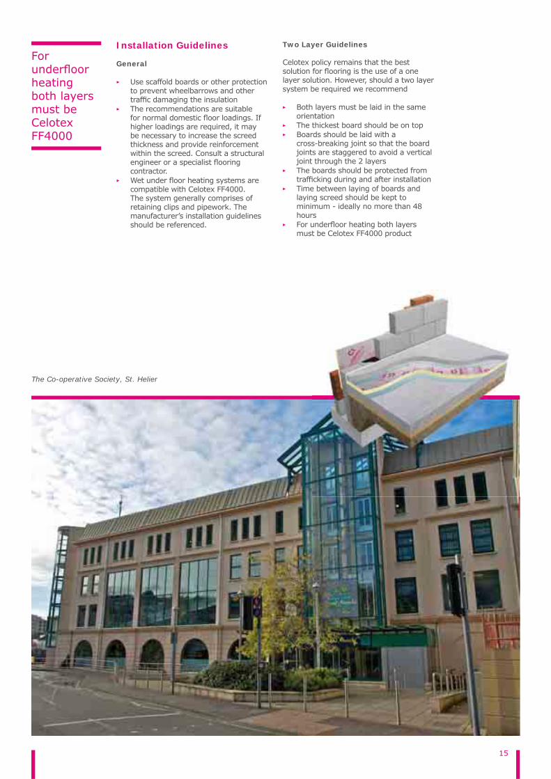
The Co-operative Society, St. Helier

16 Floors Specifi cation Guide
Concrete fl oor - under slab
▶ Level any projections from the hardcore with a thin layer of sand blinding.
▶ Install a damp proof membrane minimum (1200 gauge)with joints well folded and lapped. The membrane continue up the side of the walls until it connects with or forms the dpc course.
▶ Loose lay Celotex insulation boards across the damp proof membrane. They should be break bonded with board joints tightly butted.
▶ Place the perimeter edge insulation vertically around the edge of the fl oor slab to prevent cold bridging. The upstand should have a minimum R-value 0.75m2K/W. Ensure the top of the perimeter upstand is level with the top of the fi nished fl oor slab.
▶ Lay a polythene vapour control layer over the insulation to minimise the risk of interstitial condensation forming at the slab/insulation interface. Ensure the polythene sheet edges overlap by 150mm, taped at the joints and is turned up to cover the perimeter edge insulation.
▶ Lay concrete to required fi nished fl oor level and smooth over with fl oat fi nish.
Concrete fl oors - below a fl oor screed
▶ Level the surface of the concrete slab so that it is smooth and free from projections. Use a thin layer of sand blinding on a rough tamped slab to ensure that the insulation boards are continuously supported.
▶ Install a damp proof membrane below the Celotex. This can be over the top of a concrete slab to prevent any residual moisture within the slab contacting Celotex Insulation or below the slab.
▶ The damp proof membrane must provide continuity with the damp proof course in the surrounding walls by continuing the membrane up the side of the walls until it connects with or forms the dpc course.
▶ Loose lay Celotex insulation boards across the damp proof membrane. They should be break bonded with board joints tightly butted.
▶ Place the perimeter edge insulation vertically around the edge of the fl oor slab to prevent cold bridging. The up
stand should have a minimum R-value 0.75m2K/W. Ensure the top of the perimeter up stand is level with the top of the fi nished fl oor layer.
▶ Lay a 1000 gauge polythene vapour control layer over the insulation to minimise the risk of interstitial condensation forming at the slab/insulation interface. It also separates the moisture within the liquid screed contacting the surface of Celotex Insulation. Ensure the polythene sheet edges overlap by 150mm, taped at the joints and is turned up to cover the perimeter edge insulation.
▶ Apply a sand/cement or self levelling screed over the VCL and Celotex insulation boards to a minimum thickness of 65mm.
Concrete fl oor – under chipboard fl oor fi nish
▶ Install Celotex insulation as for under screed for the fi rst four points.
▶ Lay a 1000 gauge polythene vapour control layer over the insulation to minimise the risk of interstitial condensation forming on the slab/insulation interface. Ensure the polythene sheet edges overlap by 150mm, taped at the joints and is turned up 100mm at room perimeters behind the skirting.
▶ The chipboard must be a minimum 18mm tongued and grooved fl ooring grade type C4 to BS5669. Lay the chipboard with staggered joints, glued with a woodworking adhesive.
▶ Provide a 10-12mm gap at all perimeter and abutments to allow for expansion. This can be achieved by the use of temporary wedges.
▶ Where chipboard is butted together without a tongued and grooved joint and all external doorways (for the width of the threshold) a treated timber batten must be used in lieu of the insulation boards.
Suspended timber fl oors
▶ Install joists in the conventional manner, with solid or strut bracing as necessary (diagonal bracing may lead to thermal bridging).
▶ Measure accurately the width of each joist space to be fi lled prior to cutting
the board. Ensure there is a tight fi t between insulation and joists to minimise air leakage and heat loss.
▶ Secure the board between the joists using Celotex insulation clips or stop battens.
Insulation clips
▶ Push the insulation clips into the board at 1000mm intervals with the two prongs piercing the exposed foam down the long edge of the board.
▶ Start the clips in between joists and push the board into place. This should be a tight fi t to minimise heat loss through the gaps between the joists and insulation board.
▶ Push the board fully into the void so that the base of the insulation clip is level with the face of the joists.
▶ Nail through the base of the clip directly into the joists to provide additional fi xing.
Stop battens
▶ Where insulation is to partially fi ll the joist space, ensure there is enough joist depth for the thickness of Celotex so that it is fl ush with the top of the joists. Where under fl oor heating is to be installed on top of Celotex insulation make an allowance for the cavity space.
▶ Fix ‘stop’ battens down the side of each joist to support Celotex insulation.
▶ Push the board into the void between the rafters until it contacts the stop batten below and is fl ush with the top of the joists with no gaps to reduce air movement and minimise air leakage.
▶ Fill any gaps between the joists and insulation with a softer more pliable insulation to further reduce air movement and minimise air leakage.
▶ Maintain insulation continuity by packing the space between fi nal joist and wall with 50mm insulation. Where fl oor abuts a masonry cavity wall, ensure insulation overlaps cavity wall insulation by 150mm.
▶ Install either chipboard or softwood fl oor boarding directly onto the joists.
▶ Seal skirting board to wall and fl oor with a fl exible sealant to minimise air movement and heat loss. Seal service openings in the same way.
▶ Ensure the void below the timber fl oor is ventilated and insulation does not block openings.

17
Forge Lane Water Tower, Congleton
18 Floors Specifi cation Guide
Where underfl oor heating is to be used in a suspended timber fl oor
▶ Install Celotex with the unprinted foil surface into the air cavity for optimum thermal performance. Push the board into the void between the joists until it contacts the stop batten below.
▶ Lay a proprietary underfl oor heating system within the cavity, generally comprising pipework in coils, to the manufacturers’ guidelines.
▶ Install either chipboard or softwood fl oor boarding directly onto the joists.
▶ Ensure the void below the timber fl oor is ventilated.
Suspended timber fl oors above a vacant space – installation from below
▶ Measure accurately the width of each joist space to be fi lled prior to cutting the board. Ensure there is a tight fi t between insulation and joists to minimise air leakage and heat loss.
▶ Push the board into the void between the joists until it contacts the timber fl ooring above.
▶ Ensure any gaps between the joists and around the edges are fi lled to reduce air movement and minimise heat loss. A soft pliable insulation or expanding urethane foam can be used depending on the size.
▶ Hold the Celotex in place fl ush with the top of the rafters using ‘stop’ battens positioned along the inside of the joists.
▶ Install plasterboard under the joists where required by building regulations to provide a timed resistance to the passage of fi re.
Direct fi x to concrete soffi t – unprotected
▶ It is recommended that Celotex board joints are installed with joints break bonded.
▶ Directly fi x Celotex insulation to concrete soffi t. Fixings should be evenly laid out with a minimum of 12 fi xings per 1200x2400 board.
▶ Fixings should be installed between 50mm-150mm from the edge and corners of the board. Suitable fi xings should comprise a screw type suitable for the concrete deck into which it is
being driven, combined with a circular or rectangular plate washer having a surface area of not less than 45cm2.
▶ Please note that the foil facer of the Celotex insulation is not intended to provide a decorative fi nish. Where additional protection is required please follow the installation guidelines shown below.
Direct fi x to concrete soffi t – protected
▶ It is recommended that Celotex board joints are installed with joints break bonded.
▶ For optimum thermal performance, the unprinted foil surface should face the air cavity.
▶ Directly fi x Celotex insulation and 25mmx50mm timber fi xing battens to concrete soffi t. The timber battens should be fi xed underneath the layer of Celotex. Ensure that the timber fi xing battens are secured at 600mm centres and that the fi xings through the concrete soffi t are also at 600mm centres.
▶ Fixings should be installed between 50-150mm from the edge and corners of the board. Suitable fi xings should comprise a screw type suitable for the concrete deck into which it is being driven. Advice on suitable fi xings should be sought from the fi xing manufacturer.
▶ To provide additional protection, fi x a layer of cementitious board to the timber battens using suitable screwsor nails.
For more information please contact the Celotex Technical Centre on 01473 820850 or email [email protected]

19
Storage
Celotex insulation boards should be stored dry, fl at and clear of the ground. Only as much material as can be installed during a single working period should be removed from storage at any one time. If boards are stored under tarpaulins, care should be taken to prevent rope damage to boards.
Installation
Always install Celotex insulation boards in accordance with the instructions supplied by Celotex.
Celotex insulation boards should not be installed when the temperature is at or below 4°C and falling.
Where possible, cut the product using the Celotex Insulation Saw to minimise dust creation.
General Information
When cutting Celotex insulation, dust extraction equipment, eye protection and face masks should be provided. Dust or particles in the eyes should be washed out with liberal quantities of water. If skin is sensitive to fi bre irritation, apply a barrier cream to exposed areas before handling.
Handling
Care should also be taken to ensure that packs are not dropped on to corners or edges.
Aluminium foil edges may be sharp. Avoid sliding bare hands along board edges.
x insulation boards should not be d when the temperature is at or 4°C and falling.
possible, cut the product using thex Insulation Saw to minimise dust n.
sliding bare hands along board edges.

20 Floors Specifi cation Guide
Find out more at celotex.co.uk
Follow us on @celotex
Team up with us on
Like us on
Celotex, Lady Lane Industrial Estate, Hadleigh, Ipswich, Suffolk, IP7 6BA
T: 01473 820850 E: [email protected]