special articles on introducing the 3.5 ghz band technical ......in december 2014, the mic...
TRANSCRIPT

High-precision Clock-time-synchronization Network Equipment for Introduction of 3.5-GHz band TD-LTE
TD-LTE UTC High-precision Time Synchronization
©2016 NTT DOCOMO, INC. Copies of articles may be reproduced only for per-sonal, noncommercial use, provided that the nameNTT DOCOMO Technical Journal, the name(s) of theauthor(s), the title and date of the article appear in thecopies.
18 NTT DOCOMO Technical Journal Vol. 18 No. 2
Special Articles on Introducing the 3.5‐GHz Band
In December 2014, the MIC approved “Establishment Plan
of Specified Base Stations for Introduction of Fourth-gen-
eration Mobile Communication Systems,” and it thus be-
came possible to utilize the 3.5-GHz frequency band in Ja-
pan. NTT DOCOMO has introduced TD-LTE using this
band—combined with the existing FDD bands by means of
CA—and communication services with a maximum data
rate of 370 Mbps were launched to evolve our service called
“PREMIUM 4G” in June 2016. This article summarizes
technologies and describes characteristic features in regard
to high-accuracy time-synchronization networks—a required
future technology—for providing services based on the
TDD method (which is being introduced by NTT DOCOMO
for the first time).
Radio Access Network Development Department
Solution Services Division, DOCOMO Technology, Inc.
Shinichi Yokote Genta Nishimura
Hirotoshi Sugimoto
1. Introduction
In December 2014, the MIC allo-
cated the 3.5-GHz frequency band to
NTT DOCOMO. In accordance with a
requirement for utilization of that band,
the Time Division Duplex (TDD)*1 meth-
od must be used. Accordingly, when in-
troducing the 3.5-GHz frequency band,
NTT DOCOMO adopted TD-LTE stand-
ard technology (which is one version of
the LTE standard).
As for TD-LTE, the frequency band
can be used to the full because the fre-
quencies of the uplink and downlink
channels do not have to be separated.
On the other hand, if the signals of the
uplink and downlink channels are sent
at the same time, radiowave interference
can be generated. Extremely accurate
clock-time synchronization—between
not only our base stations but also those
of other communication carriers—is thus
necessary.
The accuracy of that clock-time syn-
chronization is specified in the Interna-
tional Telecommunication Union-Tele-
communication Standardization sector
(ITU-T) Recommendation G.8271*2 as
a time-synchronization error between
†
*1 TDD: A bidirectional transmit/receive schemethat achieves bidirectional communication byallocating different time slots to uplink and down-link transmissions that use the same frequency.
† Currently Global Business Division
NTT
DO
CO
MO
Tec
hnic
al J
ourn
al
NTT DOCOMO Technical Journal Vol. 18 No. 2 19
BCBase-station equipment
GMC BC
GPS
1.5 µs or less
Timing error due to multi-paths of propagation channel and processing delay of base-station equipment and time-synchronous equipment
Antenna
Mobile terminals
Figure 1 Condition of clock-time error in the case of TD-LTE
Table 1 Time-synchronization protocol
Protocol Synchronization accuracy Synchronization method
NTP Approx.1 ms In reference to a time standard maintained by a server, times are synchronized according
to requests from clients.
PTP 1.5 µs or less Times are synchronized by exchanging messages between equipment taking the roles of
master and slave.
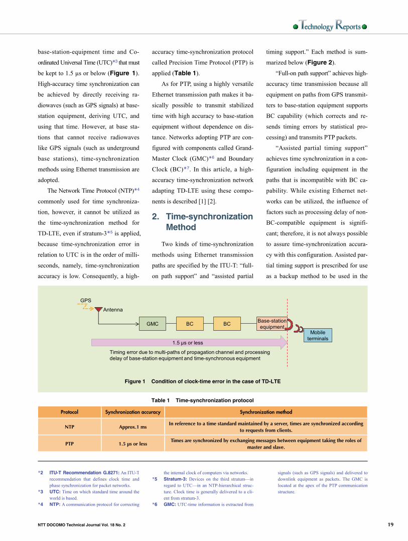
base-station-equipment time and Co-
ordinated Universal Time (UTC)*3 that must
be kept to 1.5 µs or below (Figure 1).
High-accuracy time synchronization can
be achieved by directly receiving ra-
diowaves (such as GPS signals) at base-
station equipment, deriving UTC, and
using that time. However, at base sta-
tions that cannot receive radiowaves
like GPS signals (such as underground
base stations), time-synchronization
methods using Ethernet transmission are
adopted.
The Network Time Protocol (NTP)*4
commonly used for time synchroniza-
tion, however, it cannot be utilized as
the time-synchronization method for
TD-LTE, even if stratum-3*5 is applied,
because time-synchronization error in
relation to UTC is in the order of milli-
seconds, namely, time-synchronization
accuracy is low. Consequently, a high-
accuracy time-synchronization protocol
called Precision Time Protocol (PTP) is
applied (Table 1).
As for PTP, using a highly versatile
Ethernet transmission path makes it ba-
sically possible to transmit stabilized
time with high accuracy to base-station
equipment without dependence on dis-
tance. Networks adopting PTP are con-
figured with components called Grand-
Master Clock (GMC)*6 and Boundary
Clock (BC)*7. In this article, a high-
accuracy time-synchronization network
adapting TD-LTE using these compo-
nents is described [1] [2].
2. Time-synchronization Method
Two kinds of time-synchronization
methods using Ethernet transmission
paths are specified by the ITU-T: “full-
on path support” and “assisted partial
timing support.” Each method is sum-
marized below (Figure 2).
“Full-on path support” achieves high-
accuracy time transmission because all
equipment on paths from GPS transmit-
ters to base-station equipment supports
BC capability (which corrects and re-
sends timing errors by statistical pro-
cessing) and transmits PTP packets.
“Assisted partial timing support”
achieves time synchronization in a con-
figuration including equipment in the
paths that is incompatible with BC ca-
pability. While existing Ethernet net-
works can be utilized, the influence of
factors such as processing delay of non-
BC-compatible equipment is signifi-
cant; therefore, it is not always possible
to assure time-synchronization accura-
cy with this configuration. Assisted par-
tial timing support is prescribed for use
as a backup method to be used in the
signals (such as GPS signals) and delivered todownlink equipment as packets. The GMC islocated at the apex of the PTP communicationstructure.
*2 ITU-T Recommendation G.8271: An ITU-Trecommendation that defines clock time andphase synchronization for packet networks.
*3 UTC: Time on which standard time around theworld is based.
*4 NTP: A communication protocol for correcting
the internal clock of computers via networks. *5 Stratum-3: Devices on the third stratum—in
regard to UTC—in an NTP-hierarchical struc-ture. Clock time is generally delivered to a cli-ent from stratum-3.
*6 GMC: UTC-time information is extracted from
NTT
DO
CO
MO
Tec
hnic
al J
ourn
al

High-precision Clock-time-synchronization Network Equipment for Introduction of 3.5-GHz band TD-LTE
20 NTT DOCOMO Technical Journal Vol. 18 No. 2
“Full-on path support” network structure
“Assisted partial timing support” network structure
Antenna
Antenna
BCPTP packet
BCBase-station equipmentPTP packet
L2SW (BC incompatible)
GMC
GMC BCBase-station equipment
Figure 2 Time synchronization
Antenna
BCGMC S BCSM M Base-station equipment
S
Master port Slave port
PTP packetM
Figure 3 Configuration of time-synchronization network
case that base-station equipment re-
ceives direct radiowaves (such as GPS
signals).
NTT DOCOMO is expanding TD-
LTE so that it can also be used in places
that cannot receive GPS signals (such
as underground). Accordingly, as a time-
synchronization method, full-on path
support was adopted instead of assisted
partial timing support—which is pre-
supposed to be used as a backup
method.
3. Mechanism of High-accuracy Time Synchronization
As shown in Figure 3, a time-syn-
chronization network is configured with
a GMC at its apex. In each link of this
configuration, the downlink port of up-
link equipment plays the role of “mas-
ter,” and the uplink port of downlink
equipment plays the role of “slave.”
Messages are exchanged between the
master and slave in accordance with the
PTP sequence described in the follow-
ing (Figure 4). Moreover, providing
an action that cancels delay within
equipment makes it possible to achieve
high-accuracy time synchronization.
3.1 PTP Message Type
The PTP messages are generally
classified as “announce” or “event” mes-
sages.
1) Announce Message
Announce messages are used for
communication of information about
session*8 establishment and time syn-
chronization by sending messages from
master to slave.
2) Event Message
• Sync: A message sent from mas-
ter to slave. It records the time
the message was sent from the
master.
• Delay_Req: A message returned
to the master from the slave that
received the Sync message.
• Delay_Resp: A message sent
from the master to the slave. It
records the time the Delay_Req
message was received by the
master.
3.2 PTP Sequence
Time correction can be achieved by
*8 Session: A virtual communication path fortransmitting data or the transmission of data it-self.
*7 BC: A component that re-sends clock time from uplink equipment to downlink equipmentafter correcting it.
NTT
DO
CO
MO
Tec
hnic
al J
ourn
al

NTT DOCOMO Technical Journal Vol. 18 No. 2 21
Master Slave
38
40
42
44
46
48
50
52
54
56
58
60
62
40
42
44
46
48
50
47
54
56
58
60
62
Announce
Sync (t1)
Delay_Resp (t4)
O = Offset = Slave – Master
D = Delay
t1
t4
DO
t2 – t1 = Delay + Offset = 47 – 40 = 7
t4 – t3 = Delay – Offset = 53 – 52 = 1
Delay = ((t2 – t1) + (t4 – t3))/ 2 = 4
Offset = ((t2 – t1) – (t4 – t3))/ 2 = 3
t2
t351
53
(1) Transmission time (t1) is stamped, and a Sync message is sent.
(2) Receival time (t2) is recorded.
(3) Calculation of time difference from master to slave
(4) Delay_Req-message transmission time (t3) is recorded.
(5) Receival time (t4) is recorded.
(6) Receival time (t4) is stamped, and a Delay_Resp message is sent.
(7) Calculation of time difference from slave to master
Delay_Req
52
Figure 4 PTP sequence
determining the time difference between
the master and slave and calculating the
transmission-path delay and time lag
(hereinafter referred to as “offset”) be-
tween equipment (Fig. 4).
1) Calculation of Time Difference from
Master to Slave
(1) The master sends a Sync mes-
sage [stamped with the time it
was sent (t1)] to the slave.
(2) The slave records the time (t2)
that it received the Sync message.
(3) The slave determines the time
difference from the master to the
slave from t1 and t2 (i.e., 47 –
40 = 7, as shown in the middle
of Fig. 4).
2) Calculation of Time Difference from
Slave to Master
(4) The slave sends a Delay_Req
message to the master, and it rec-
ords the time (t3) that the mes-
sage was sent.
(5) The master receives the Delay_
Req message and records the
time (t4) it receives the message.
(6) The master sends a Delay_Resp
message (stamped with t4) to
the slave.
(7) The slave receives the Delay_
Resp message and determines
the difference between t4 and t3
(i.e., t4 – t3 = 53 – 52 = 1, as
shown in the middle of Fig. 4).
3) Calculation of Transmission-path
Delay and Offset
Transmission-path delay and offset
are calculated on the basis of a precon-
dition under which the transmission-path
delay time between the master and slave
is symmetrical as follows:
• transmission-path delay = {(t2 –
t1) + (t4 – t3)}/2 = (7 + 1)/2 = 4
• offset = {(t2 – t1) – (t4 – t3)}/2
= (7 – 1)/2 = 3
In the case that transmission-path
distances from the master to the slave
NTT
DO
CO
MO
Tec
hnic
al J
ourn
al

High-precision Clock-time-synchronization Network Equipment for Introduction of 3.5-GHz band TD-LTE
22 NTT DOCOMO Technical Journal Vol. 18 No. 2
GMC
SFP
BC
SFP SFP
(1) Time-stamp processing
(2) Correction value added to collection field
(3) Calculation of offset of time stamp and correction value
PTP packet
M S M
PTP packet
Internal delay
Downlink equipment
S
Antenna
Small Form-factor Pluggable (SFP): A removable module that can be installed in equipment in accordance with the communication standards in use.
GPS receiver module
Clock-supply unit
Clock-supply unit
PTP processor
PTP processor
Figure 5 Mechanism of internal-delay cancellation for GMC and BC equipment
and from the slave to the master are
symmetric, arrival times at the master
and slave will be consistent. Calculat-
ing the total of the transmission-path
delay and offset and dividing that value
in two therefore gives the transmission-
path delay time. And dividing the dif-
ference in those values in two gives the
offset. The slave always performs time
correction within the equipment in which
it is installed on the basis of the trans-
mission-path delay time and offset. As
a result, high-accuracy time synchroni-
zation between each session of PTP
equipment (GMC and BC) is accom-
plished.
3.3 Cancellation of Internal
Equipment Delay
To correct delay occurring within
equipment, a correction field*9 including
PTP packets is used. Adding a correc-
tion value to the event message sent by
the master allows the slave to cancel the
internal delay of the master (Figure 5).
4. Outline of Functions of PTP Equipment
4.1 Functional Block
As shown in Figure 6, the GMC
has a GPS receiver module (for receiv-
ing signals like GPS ones and extracting
time information from them), a clock-
supply unit (which houses a Sync-E*10
processing block) for storing that infor-
mation as the system clock of the equip-
ment in question. It also has a PTP pro-
cessing block (for generating and em-
bedding time stamps from the clock-
supply block in PTP packets) and a PPS
processing block for sending 1 Pulse
Per Second (1PPS)*11 signals. In con-
trast to the functional blocks of the GMC,
those of the BC do not include a GPS
receiver module.
4.2 Combined Use with Sync-E
Although time synchronization is
executed under the assumption that fre-
quency synchronization*12 is imposed,
frequency synchronization under PTP
executed on Ethernet networks is inde-
pendent in terms of each piece of equip-
ment, and the whole network is asyn-
chronous. On the other hand, Sync-E
operates on a physical layer; therefore,
frequency synchronization can be per-
formed with high accuracy regardless
of fluctuations in communication vol-
ume, and the whole network is syn-
chronous. Under those circumstances,
NTT DOCOMO judged that combined
use of PTP and Sync-E would be
*12 Frequency synchronization: A conditionunder which the speed at which time is kept isconsistent from one piece of equipment to thenext.
*9 Correction field: A field including PTP pack-ets used for transmitting internal equipment de-lay.
*10 Sync-E: A method for synchronizing frequen-cies on the physical layer. All equipment on atransmission route performing synchronizationmust handle Sync-E.
*11 1PPS: A pulse signal sent once per second.
NTT
DO
CO
MO
Tec
hnic
al J
ourn
al

NTT DOCOMO Technical Journal Vol. 18 No. 2 23
GMC
SFP
BC
SFP SFP
PTP packet
Sync-E
M S MPTP packet
Sync-E
Clock extracted from Sync-E
Clock is supplied from SSU.
PTP processor
Downlink equipment
S
Antenna
GPS receiver module
Clock-supply unit
PTP processor
Clock-supply unit
Figure 6 Functional blocks of GMC and BC
effective for the high-accuracy time syn-
chronization required by TD-LTE, so we
adopted a method combining PTP and
Sync-E. Combining PTP and Sync-E in
this manner for all equipment of a time-
synchronization network makes it pos-
sible to improve the time-synchroni-
zation accuracy along a whole (“end-
to-end”) communication route because
the times for processing PTP packets
are consistent.
4.3 BMCA
To handle failures, BC equipment
can combine a maximum of two uplink
PTP units in a redundant configuration
by applying a function called a Best-
Master Clock Algorithm (BMCA). This
function is accomplished as a result of
the master recording the performance
value of its own time information in the
announce message and regularly com-
municating with the slave. The slave can
receive time information from two mas-
ters, judge the masters on the basis of
their performance values, and select the
BMC accordingly. Which of the two
pieces of received time information to
use for synchronization is judged by
means of a “BMCA sequence” (as shown
in Figure 7). Furthermore, although
synchronization is performed with the
selected BMC, if communication with
that BMC fails, time synchronization is
performed with the other master. The
performance value included in the time
information received from the masters
is classified as one of the following six
kinds (and the master with the highest
value is selected).
(1) Priority 1
A priority 1 value indicates the
unconditional priority of GMCs. It is
a set value specified in IEEE1588-
2008*13 and cannot be changed. In
the case of BC, priority 1 is passed
down to downlink equipment.
(2) Clock Class
“Clock Class” is a value that in-
dicates the synchronization state be-
tween UTC and the time sent from
the master (as shown in Table 2).
In the case that the two are syn-
chronized, a Clock Class “6” (here-
inafter referred to as “CC6”) is sent.
(3) Clock Accuracy
“Clock Accuracy” is a value that
indicates the accuracy of time. The
values handled by NTT DOCOMO’s
PTP equipment are shown in Table 3.
(4) Offset Scaled log Variance
“Offset Scaled log variance” in-
dicates the stability of clock-synchro-
nization accuracy as shown in Table 4.
(5) Priority 2
“Priority 2” is a value that indi-
cates the unconditional priority of
GMCs. However, unlike priority 1,
it can be varied; that is, by setting
*13 IEEE1588-2008: An IEEE standard that de-fines a protocol for high-accuracy clock-timesynchronization used for financial and commu-nication systems.
NTT
DO
CO
MO
Tec
hnic
al J
ourn
al

High-precision Clock-time-synchronization Network Equipment for Introduction of 3.5-GHz band TD-LTE
24 NTT DOCOMO Technical Journal Vol. 18 No. 2
Table 2 Clock Class
Value (hexadecimal notation) Explanation of condition
6 Synchronization with UTC
140, 150, 160 GMC is hold over.
165 BC is not synchronized with master.
248 GMC: During initial start-up operation or hold-over
BC: During initial start-up operation
Table 3 Clock Accuracy
Value (hexadecimal notation) Explanation of condition
21 Time accuracy within 100 ns
FE unknown
Table 4 Offset Scaled log Variance
Value (hexadecimal notation) Explanation of condition
4E5D Synchronization with UTC
FFFF Not synchronized with UTC
A < B
A < B
A < B
A < B
A < B
A < B
A > B
A > B
A > B
A > B
A > B
A > B
GMC (A) chosen by master
GMC (B) chosen by master
Announce message
A=B
A=B
A=B
A=B
A=B
GMC(A)
GMC(B)
BC
On the slave side, master is decided according to parameters in the announce message.
(IEEE1588-2008 specified operation)
S
M M
S
(1) Priority 1 value
(2) Clock Class value (Table 2)
(3) Clock Accuracy value
(Table 3)
(4) Offset Scaled log Variance value
(Table 4)
(5) Priority 2 value
(6) Identity value
Figure 7 BMCA sequence
Priority 2, the user can select the
BMC that must be synchronized.
(6) Identity
“Identity” is a value calculated
from the Media Access Control (MAC)
address*14 of equipment as a unique
value allocated to each piece of
equipment.
5. Aiming to Provide Stable Services
5.1 Improvement of Operation of
PTP Equipment
When the GMC is synchronized with
UTC, delivery of clock time (along with
CC6) to downlinks starts.
*14 MAC address: A 12-digit fixed physical ad-dress allocated to an Ethernet board.
NTT
DO
CO
MO
Tec
hnic
al J
ourn
al

NTT DOCOMO Technical Journal Vol. 18 No. 2 25
GMC
(2) CC6 transmission
(3) Time-error-convergence operation
BC1 BC2 BC3 BC4 BC5
Base-station
processing
(4) ▲ Radiowave emission
After time-error convergence
Antenna
(1) Disaster recovery
Completion
Completion
Completion
Completion
Completion
Mobile terminals
GPS
BC1
BC2
BC3
BC4
BC5
Base-station equipment
Figure 8 Convergence of time errors
Building
Direct wave
Building
BuildingReflected wave
(multipath)
Direct wave
Antenna
Antenna
GMC
GMC
Figure 9 Direct waves and multipath waves
On the other hand, due to periodic
failures of time-synchronization net-
works, even under the condition that an
error between the system clock and UTC
occurs, if CC6 is received, clock time is
delivered to subordinate equipment. As
a result, it has been typically necessary
to periodically stop services delivered
on the basis of TD-LTE. As a counter-
measure against that necessity, by re-
viewing the behavior of clock-time er-
ror convergence and significantly short-
ening the time required for convergence,
it is possible to shorten the time that
failures effect services (Figure 8).
5.2 Influence of Multipaths
Radiowaves (like GPS signals) can
be categorized as direct waves or re-
flected waves according to the surround-
ing environment (Figure 9). With re-
flected waves referred to as “multipath
waves,” in regard to accurate clock-
time synchronization, clock-time error
is increased (Figures 10 and 11). At
present, it is impossible to completely
exclude multipath waves; accordingly,
at NTT DOCOMO, while considering
increase in clock-time error due to the
influence of multipath waves, we are
NTT
DO
CO
MO
Tec
hnic
al J
ourn
al

High-precision Clock-time-synchronization Network Equipment for Introduction of 3.5-GHz band TD-LTE
26 NTT DOCOMO Technical Journal Vol. 18 No. 2
Maximum time error = – 42 nanoseconds
Figure 10 Maximum time error in an environment with numerous direct waves
Maximum time error = – 412 nanoseconds
Figure 11 Maximum time error in an environment with numerous multipaths
building networks with a limited num-
ber of BC stages connected to downlink
equipment of GMC.
6. Conclusion
In this article, standard specifica-
tions and operations in regard to equip-
ment composing high-accuracy time-
synchronization networks targeting in-
troduction of 3.5-GHz-band TD-LTE
are explained. At present, standardiza-
tion of, for example, operation during
failures is progressing, and while con-
sidering this trend, we will continue to
apply this standardized technology to
NTT DOCOMO networks as necessary.
REFERENCES [1] T. Yoshihara et al.: “Radio Equipment
and Antennas for Advanced C-RAN
Architecture,” NTT DOCOMO Technical Journal, Vol.17, No.2, pp.19-24, Oct. 2015.
[2] M. Fujii et al.: “Base-station Equipment with the Aim of Introducing 3.5-GHz Band TD-LTE,” NTT DOCOMO Technical Journal, Vol.18, No.2, pp.8-13, Oct. 2016.
NTT
DO
CO
MO
Tec
hnic
al J
ourn
al