special provisions worcester federal aid project nos. cmq
TRANSCRIPT

Massachusetts Department of Transportation Highway Division Proposal No. 601368-108807
A00801 - 1
DOCUMENT A00801
SPECIAL PROVISIONS
WORCESTER Federal Aid Project Nos. CMQ-0033(003)X, HSI-0033(003)X & STP-0033(003)X Roadway Reconstruction and Related Work (Including Signals) along a Section of
Grafton Street (Route 122) Labor participation goals for this project shall be 15.3% for minorities and 6.9% for women for each job category. The goals are applicable to both contractor’s and subcontractor’s on-site construction workforce. Refer to document 00820 for details.
SCOPE OF WORK This project is a streetscape improvement project along the Grafton Street corridor from Franklin Street to Massasoit Road and includes removing and replacing existing sidewalks, driveways, signs and posts, and street lighting throughout the project limits. The work includes unclassified excavation, milling, full depth hot mix asphalt pavement, warm mix asphalt overlay, cement concrete sidewalk and wheelchair ramps, minor drainage improvements, granite curb and edging, pavement markings, signs, traffic signal system, reconstruction of existing traffic signal systems, landscaping and other incidental work. The existing pavement will be micro-milled and overlaid with new hot mix asphalt, except in certain areas where the existing pavement will be removed and replaced with full depth pavement. The existing curb will be removed and reset, some new curb added in bulb-out areas and new cement concrete sidewalks with decorative stamped cement concrete accent strips will be constructed in compliance with the Americans with Disabilities Act Accessibility Guidelines (ADAAG) including the installation of texturized synthetic pavement at all crosswalk locations. All work under this contract shall be done in conformance with the Standard Specifications for Highways and Bridges dated 1988, the Supplemental Specifications dated April 1, 2019; and the Interim Supplemental Specifications contained in this contract, the 2017 Construction Standard Details, the 1990 Standard Drawings for Signs and Supports; the 1996 Construction and Traffic Standard Details (as relates to the Pavement Markings details only); The 2015 Overhead Signal Structure and Foundation Standard Drawings, the 2009 Manual on Uniform Traffic Control Devices (MUTCD) with Massachusetts Amendments and the Standard Municipal Traffic Code; the 1968 Standard Drawings for Traffic Signals and Highway Lighting; the latest edition of American Standard for Nursery Stock; the Plans and these Special Provisions.
Massachusetts Department of Transportation Highway Division Proposal No. 601368-108807
A00801 - 2
CONTRACTOR QUESTIONS AND ADDENDUM ACKNOWLEDGEMENTS Prospective bidders are required to submit all questions to the Construction Contracts Engineer by 1:00 P.M. on the Thursday before the scheduled bid opening date. Any questions received after this time will not be considered for review by the Department. Contractors should email questions and addendum acknowledgements to the following email address [email protected] The MassDOT project file number and municipality is to be placed in the subject line. SUBSECTION 7.05 INSURANCE REQUIREMENTS B. Public Liability Insurance The insurance requirements set forth in this section are in addition to the requirements of the Standard Specifications and supersede all other requirements. Paragraphs 1 and 2 The Massachusetts Department of Transportation and applicable railroads shall be named as additional insureds. Paragraph 4 Asbestos Liability Insurance shall be obtained for this project. The Contractor and the Massachusetts Department of Transportation shall be named as additional insureds. WORK SCHEDULE The Contractor shall work standard work hours from 7:00 AM to 3:30 PM, Monday thru Friday, unless otherwise approved by the Engineer. Any lane closures, lane shifts, trenching, or work that will disrupt travel on the existing roadways shall not be done from 6:00 AM to 9:00 AM and from 3:00 PM to 6:00 PM. Note: There are two properties within the project limits that are scheduled to be in construction for 2020. The gas station at 334 Grafton Street on the corner of Grafton Street and Houghton Street, on land owned by N/F Skaff Petroleum and the property at 74 Grafton Street, on land owned by Cahill Meadows, LLC. Coordination with the associated contractor may be required for access and/or sequence of construction activities during this time. Coordination can be made through the City of Worcester Engineering Department.

Massachusetts Department of Transportation Highway Division Proposal No. 601368-108807
A00801 - 3
PROPRIETARY PRODUCTS A letter discussing the following products as a proprietary specification pursuant to M.G.L. c. 30, § 39M(b) has been filed with MassDOT.
• Street Light Pole and Luminaire: o Description: Holophane “Atlanta Style, Camden Cross Arm, North Yorkshire”
series post with “Memphis Teardrop LED 2” luminaire o Catalog Numbers:
• Street Light Pendant Luminaire: MPL2-P20U-40K-AS-BK-TG-3-S-NL
• Street Light Arm: CAM72/1CABKH • Pole and Base: NYS21FTB17P05BK R132C S186A E138A • Receptacle: FGIUL-SBKH • Banner Arm: BBA24BOH4MXXBK
• Street Light Pole and Luminaire under Overpass (10 foot):
o Description: Holophane “Atlanta Style North Yorkshire” 10-foot ornamental light post with “Holophane “Washington Postlite LED Series Luminaire” Catalog Numbers:
• Post Top Luminaire: “Holophane” catalog number “AWDE2 P30 40K AS M BK 5 M S G P7 NL1X1”
• Pole and Base (10 foot): Holophane catalog number “NY-A-10-F5J-17-P05-AGB-BK
• Parking Meters: o Description: IPS “M5” Single-Space Smart Parking Meter
CONTRACTOR/SUBCONTRACTOR CERTIFICATION – CONTRACT COMPLIANCE (Revision 03-23-10) Pursuant to 23 C.F.R. § 633.101 et seq., the Federal Highway Administration requires each contractor to “insert in each subcontract, except as excluded by law or regulation, the required contract provisions contained in Form FHWA–1273 and further requires their inclusion in any lower tier subcontract that may in turn be made. The required contract provisions of Form FHWA–1273 shall not be incorporated by reference in any case. The prime contractor shall be responsible for compliance by any subcontractor or lower tier subcontractor with the requirements contained in the provisions of Form FHWA–1273.” The prime contractor shall therefore comply with the reporting and certification requirements provided in MassDOT’s CONTRACTOR/SUBCONTRACTOR CERTIFICATION Form (DOT-DIST-192) certifying compliance with 23 C.F.R. § 633.101 for each subcontract agreement entered into by the contractor. The contractor shall provide a fully executed original copy of said CONTRACTOR/SUBCONTRACTOR CERTIFICATION Form to MassDOT upon execution of any subcontract agreement. Failure to comply with the reporting and certification requirement of the CONTRACTOR/SUBCONTRACTOR CERTIFICATION Form may result in action against the prequalification status of the prime contractor with MassDOT.
Massachusetts Department of Transportation Highway Division Proposal No. 601368-108807
A00801 - 4
CONTRACT AWARD AND NOTICE TO PROCEED PROCEDURES (Amending and Supplementing Subsections 3.03 and 3.05) The prepared Contract Package is to be completed in duplicate by the successful Bidder who shall execute and deliver the Contract Package and furnish the required surety to the Department. The date of the Contract shall be the date of the Bidder’s signature and shall be typed on all forms by the successful Bidder. The Contract Package consists of the contract forms for execution all of which must be returned. These documents are available on www.bidx.com. as a separate file. The company’s corporate seal should be affixed to both the Contract and bonds. The Board of Director’s Vote will indicate who is authorized to sign and execute the Contract and bonds and affix the corporate seal. The vote shall show that said vote is in full force and effect and has not been amended or rescinded. The vote of the board of directors should be dated the same date as indicated on the contract form and should bear the imprint of the company’s corporate seal. ACCESS MASSDOT HIGHWAY INFORMATION ON WEBSITE Access MassDOT Highway Information related to Construction, Design/Engineering, Contractor/Vendor Information, Approved Materials and Fabricators, Manuals, Publications and Forms at: http://www.mass.gov/massdot/highway Select Doing business with us NOTIFICATION OF FUNDING SOURCES FOR WORK TO BE PAID BY OTHERS This contract contains work that shall be paid by the City of Worcester. The said City shall be responsible for construction costs associated with a Non-Participating Agreement with MassDOT. This contract has an agreement with the City of Worcester whereas when the construction costs for the contract scope exceed the total participating contract bid price by more than ten percent (10%), the City shall be responsible for the amount over 110% of the total participating contract bid price.

Massachusetts Department of Transportation Highway Division Proposal No. 601368-108807
A00801 - 5
NORTHERN LONG-EARED BAT PROTECTION The U.S. Fish and Wildlife Service (USFWS) has listed the northern long-eared bat as threatened under the Endangered Species Act (ESA) and the following requirements exist to protect the bat and its habitat. This project has been consulted with the USFWS through the Optional Framework to Streamline Section 7 Consultation and is consistent with the Programmatic Biological Opinion under the authority of section 4(d) of the Endangered Species Act and the Final 4(d) Rule published in the Federal Register on January 14, 2016. No conservation measures or time of year restrictions on tree cutting are required. If additional cutting is proposed by the Contractor that is outside the scope of this contract, additional review is required by the MassDOT Highway Division’s Environmental Services Section, additional review may be required by the USFWS, and time of year restrictions could apply to such tree cutting. HOLIDAY WORK RESTRICTIONS FOR CALENDAR YEAR 2019 (Supplementing Subsection 7.09) The District Highway Director (DHD) may authorize work to continue during these specified time periods if it is determined by the District that the work will not negatively impact the traveling public. Below are the holiday work restrictions for the calendar year 2019. New Year’s Day (Federal Holiday) Tuesday, January 1, 2019: No work on major arterial roadways from 5:00 AM on Friday, December 2 8 , 2018 until the normal start of business on Wednesday, January 2 , 2019. No work on local roadways on the holiday without permission by the DHD and the local police chief. Martin Luther King's Birthday (Federal Holiday) Monday, January 21, 2019: No work restrictions due to traffic concerns however work on local roadways requires permission by the DHD and local police chief. President's Day (Federal Holiday) Monday, February 1 8 , 2019: No work restrictions due to traffic concerns however work on local roadways requires permission by the DHD and local police chief. Evacuation Day (Suffolk County State Holiday) Sunday, March 17, 2019: No work restrictions due to traffic concerns.

Massachusetts Department of Transportation Highway Division Proposal No. 601368-108807
A00801 - 6
HOLIDAY WORK RESTRICTIONS FOR CALENDAR YEAR 2019 (Continued) Patriot's Day (State Holiday) Monday, April 15, 2019: Work restrictions will be in place for Districts 3, 4 and 6 along the entire Boston Marathon route and any other locations that the DHD in those districts determine are warranted so as to not to impact the marathon. All other districts work restrictions will be as per DHD. Mother’s Day Sunday, May 12, 2019: No work on Western Turnpike and Metropol i tan Highway System from 5:00 AM on Friday, May 10, 2019 until the normal start of business on Monday, May 13, 2019. Memorial Day (Federal Holiday) Monday, May 27, 2019: No work on major arterial roadways from 5:00 AM on Friday, May 24, 2019 until the normal start of business on Tuesday, May 28, 2019 Bunker Hill Day (Suffolk County State Holiday) Monday, June 17, 2019: No work restrictions due to traffic concerns. Independence Day (Federal Holiday) Thursday, July 4, 2019: No work on major arterial roadways from 5:00 AM on Wednesday, July 3, 2019 until the normal start of business on Friday, July 5, 2019. Labor Day (Federal Holiday) Monday, September 2 , 2019: No work on major arterial roadways from 5:00 AM on Friday, August 30, 2019 until the normal start of business on Tuesday, September 3 , 2019. Columbus Day (Federal Holiday) Monday, October 1 4 , 2019: No work on major arterials from 5:00 AM on Friday, October 1 1 , 2019 until the normal start of business on Tuesday, October 1 5 , 2019. DHD may allow work in those areas on a case by case basis and where work is behind barrier and will not impact traffic. Veterans' Day (Federal Holiday) Monday, November 11, 2019: No work restrictions due to traffic concerns.
Massachusetts Department of Transportation Highway Division Proposal No. 601368-108807
A00801 - 7
HOLIDAY WORK RESTRICTIONS FOR CALENDAR YEAR 2019 (Continued) Thanksgiving Day (Federal Holiday) Thursday, November 28, 2019: No work on major arterials from 5:00 AM on Wednesday, November 27, 2019 until the normal start of business on the Monday, December 2 , 2019. Christmas Day (Federal Holiday) Wednesday, December 25, 2019: No work on major arterial roadways from 5:00 AM on Tuesday, December 24, 2019 until the normal start of business on Thursday, December 26, 2019. BIDDERS LIST Pursuant to the provisions of 49 CFR Part 26.11 all official bidders will be required to report the names, addresses and telephone numbers of all firms that submitted bids or quotes in connection with this project. Failure to comply with a written request for this information within 15 business days may result in a recommendation to the Prequalification Committee that prequalification status be suspended until the information is received. The Department will survey all firms that have submitted bids or quotes during the previous year prior to setting the annual goal and shall request that each firm report its age and gross receipts for the year. EVERSOURCE EMERGENCY TELEPHONE NUMBERS ELECTRIC: Outage/ Emergency: 800-592-2000 or 844-726-7562 New Service: 1-888-633-3797 (1-888-need pwr) Customer Support: 1-800-340-9822 NATIONAL GRID EMERGENCY TELEPHONE NUMBERS GAS: Emergency: 1-800-233-5325 New Service: 1- 877-696-4743 Customer Support: 1-800-732-3400
Massachusetts Department of Transportation Highway Division Proposal No. 601368-108807
A00801 - 8
NOTICE TO OWNERS OF UTILITIES Written notice shall be given by the Contractor to all public service corporations or municipal and state officials owning or having charge of publicly or privately-owned utilities of the intent to commence operations affecting such utilities at least one (1) week in advance of the commencement of such operations. The Contractor shall at the same time file a copy of this notice with the Engineer. The Contractor shall ensure that all affected agencies and utilities are notified. The Contractor may access a current list of utility contacts at: https://www.mass.gov/info-details/utility-contacts-by-district-and-municipality The following are the names of owners and representatives of the principal utilities affected, but completeness of this list is not guaranteed by the Department: City of Worcester Engineering Department Mark Elbag 20 East Worcester Street Director Worcester, MA 01604 Phone: (508) 799-1454 Worcester Fire Department Chief Michael Lavoie 141 Grove Street Phone: (508) 799-1821 Worcester, MA 01605 Worcester Police Department Chief Steven M. Sargent 9-11 Lincoln Square Phone: (508) 799-8600 Worcester, MA 01608 Shotspotter Program Sargent Anthony Petrone 9-11 Lincoln Square [email protected] Worcester, MA 01608 Phone: (508) 799-8600 Department of Public Works Paul J. Moosey 20 East Worcester Street Commissioner Worcester, MA 01604 Phone: (508)-929-1300 Parks & Recreation Robert C. Antonelli, Jr. 50 Skyline Drive Assistant Commissioner Worcester, MA 01605 Phone: (508)-799-1190
Massachusetts Department of Transportation Highway Division Proposal No. 601368-108807
A00801 - 9
NOTICE TO OWNERS OF UTILITIES (Continued) Electric National Grid Jack Saraiva 1250 Brayton Point Road Phone: (508) 962-6298 Somerset, MA 02725 Telephone Verizon Karen Mealey 385 Myles Standish Blvd. Phone: (774)-409-3160 Taunton, MA 02780 Gas Eversource Gas Jeffrey Evans-Mongeon 157 Cordaville Road, 3113 Phone: (508) 305-6970 Southborough, MA 01772 Cable Crown Castle Rick Molnar 80 Central Street Phone: (774) 243-9789 Boxborough, MA 01719 Charter Communications David Poplawski 301 Barber Avenue Phone: (774) 823-3214 Worcester, MA 01606 AT&T/Teleport Communications America, c/o Siena Engineering Group Hayleigh Walker 50 Mall Road – Suite 203 Phone: (781) 221-8400 x7023 Burlington, MA 01803 MAILBOX RELOCATION Mailbox labeled R&R USPS mail box (BO), located at Station 30+75 LT, shall be removed and reset by the United States Postal Service (USPS). The Contractor shall coordinate the relocation with the USPS. Coordination for the relocating of the mailbox will be incidental to the contract work and will not be paid for separately. The concrete pad for the relocated mailbox shall be constructed by the Contractor. The pad shall meet the construction standards for cement concrete walks and will be paid for under Item 701. DESIGNER/PROJECT MANAGER DESIGNER MassDOT PROJECT MANAGER Christine Champeau Filbert Yee, Project Manager Vanasse Hangen Brustlin, Incorporated 857.368.9326 508.513.2705
Massachusetts Department of Transportation Highway Division Proposal No. 601368-108807
A00801 - 10
MATERIAL REMOVED AND STACKED The Contractor shall carefully remove, transport, and stack all material that, in the opinion of the Engineer, is salvageable. The material shall be stacked at the City of Worcester Department of Public Works (DPW) Ballard Yard located at 1065 Millbury Street Worcester, MA 01607. The Contractor shall coordinate with the City of Worcester DPW to schedule drop-off time and location. DRAINAGE STRUCTURES Where new pipe is shown on the drawings to be connected into an existing drainage structure to remain, the existing structure shall be first cleaned to remove all mud, debris and other materials. The existing structure wall shall be carefully and neatly cut to provide the minimum size opening required for the insertion of the new pipe. The proposed pipe end shall be set or cut off flush with the inside face of the existing structure wall and the remaining space around the pipe completely filled with cement grout for the full thickness of the structure wall. Existing shaped inverts shall be reconstructed as necessary to provide a smooth and uniform flow channel from the new pipe through the existing structure. No separate payment will be made for the cost of connecting new pipes into existing structures, cleaning and necessary alterations of existing structures, but all costs in connection therewith shall be included in the unit prices bid for the various pipe items. EQUIVALENT SINGLE AXLE LOADS (ESALS) The estimated traffic level to be used for SUPERPAVE HMA mixture designs for this contract, expressed in Equivalent Single Axle Loads (ESALs) for the design travel lane over a 20-year period, is 8.0 Million 18-kip (80-kn) ESALs.
Massachusetts Department of Transportation Highway Division Proposal No. 601368-108807
A00801 - 11
ARCHITECTURAL ACCESS BOARD TOLERANCES The Contractor is hereby notified that they are ultimately responsible for constructing all project elements in strict compliance with the current AAB/ADA rules, regulations and standards. All construction elements in this project associated with sidewalks, walkways, wheelchair ramps and curb cuts are controlled by 521CMR - Rules and Regulations of the Architectural Access Board (AAB). The AAB Rules and Regulations specify maximum slopes and minimum dimensions required for construction acceptance. There is no tolerance allowed for slopes greater than the maximum slope nor for dimensions less than the minimum dimensions. Contractors shall establish grade elevations at all wheel chair ramp locations, and shall set transition lengths according to the appropriate table in the Construction Standards (or to the details shown on the plans). All wheelchair ramp joints and transition sections which define grade changes shall be formed, staked and checked prior to placing cement concrete. All grade changes are to be made at joints. BUY AMERICA PROVISIONS (23 CFR 635.410) (Supplementing Subsection 6.01 Source of Supply and Quality) The Buy America Federal Regulation (23 CFR 635.410) requires that all manufacturing processes for steel and iron to be permanently incorporated in Federal-Aid Highway Construction Projects must occur in the United States. Foreign steel and iron can be used if the cost of the materials does not exceed 0.1% of the total Contract cost or $2,500, whichever is greater. The action of applying a coating to a covered material (i.e., steel and iron) is deemed a manufacturing process subject to Buy America. Coating includes epoxy coating, galvanizing, painting and any other coating that protects or enhances the value of a material subject to requirements of Buy America.

Massachusetts Department of Transportation Highway Division Proposal No. 601368-108807
A00801 - 12
CARGO PREFERENCE ACT Work under this contract shall comply with the Cargo Preference Act of 1954 (CPA) and implementing regulations (46 CFR Part 381). (b) Contractor and Subcontractor Clauses. Use of United States-flag vessels: The contractor agrees- "(1) To utilize privately owned United States-flag commercial vessels to ship at least 50 percent of the gross tonnage (computed separately for dry bulk carriers, dry cargo liners, and tankers) involved, whenever shipping any equipment, material or commodities pursuant to this contract, to the extent such vessels are available at fair and reasonable rates for United States-flag commercial vessels. "(2) To furnish within 20 days following the date of loading for shipments originating within the United States or within 30 working days following the date of loading for shipments originating outside the United States, a legible copy of a rated, 'on-board' commercial ocean bill-of-lading in English for each shipment of cargo described in paragraph (b) (1) of this section to both the Contracting Officer (through the prime contractor in the case of subcontractor bills-of-lading) and to the Division of National Cargo, Office of Market Development, Maritime Administration, Washington, DC 20590. "(3) To insert the substance of the provisions of this clause in all subcontracts issued pursuant to this contract" SUBSECTION 8.02 SCHEDULE OF OPERATIONS Replace this subsection with the following: An integrated cost and schedule controls program shall be implemented by the Contractor to track and document the progress of the Work from Notice to Proceed (NTP) through the Contractor Field Completion (CFC) Milestone. The Contractor’s schedules will be used by the Engineer to monitor project progress, plan the level-of-effort required by the Department’s work force and consultants and as a critical decision-making tool. Accordingly, the Contractor shall ensure that it complies fully with the requirements specified herein and that its schedules are both accurate and updated as required by the specification throughout the life of the project. Detailed requirements are provided in Division II, Section 722 Construction Scheduling.
Massachusetts Department of Transportation Highway Division Proposal No. 601368-108807
A00801 - 13
NEW INTRODUCTIONS OF INVASIVE PLANTS INTO OR AROUND THE SITE (Supplementing Subsections 7.01(D) Plant Pest Control and 7.13 Protection and Restoration of Property) The Contractor shall ensure that no invasive plant species, as defined and listed by the Massachusetts Invasive Plant Advisory Group, are introduced or moved around the site by construction activities either by improperly cleaned construction equipment or importation of infected materials such as borrow, compost, nursery stock, seed, or hay bales. Corrective measures, if necessary, shall be made by the Contractor as directed by the Engineer. The Contractor shall be solely responsible for all costs associated with ensuring that invasive species are not introduced or moved around the site by construction activities and for all corrective measures required for as long as necessary to eliminate the introduced invasive plant species and prevent re-establishment of same. VALUE ENGINEERING CHANGE PROPOSAL This Subsection defines the conditions and requirements which apply to Value Engineering Change Proposals (“VECPs”). The purpose of this provision is to encourage the Contractor to propose changes in certain project requirements that will maintain the project’s functional requirements at a savings in contract time, contract price, or both. The net savings obtained by using a VECP that meets the conditions and requirements set forth here will be shared by the Contractor and MassDOT. VECP’s under this provison are to be initiated, developed and submitted to MassDOT by the Contractor. The VECP must show the contemplated changes to the Drawings, Specifications and other requirements in the Contract. When a VECP submitted pursuant to this section is fully accepted by MassDOT, the VECP will be implemented by the Contractor and paid using the current cost and resource loaded schedule. Contractor shall demonstrate that the VECP is equal to, or better than, the original design or material; that there is an interest in public safety within the VECP; that there is a life-cycle cost benefit; and/or that end users will benefit from the shortened schedule. VECPs shall be consistent with the MassHighway/MassDOT Standard Specifications for Highways and Bridges and other applicable reference documents and directives. Any proposed deviation from these documents will need to be clearly identified in the VECP Proposal Documents, and must be approved by MassDOT’s Chief Engineer before accepting this VECP. A. In order to be considered for MassDOT review each VECP shall:
1. Be clearly labeled pursuant to this Subsection;
2. Yield a net savings at least two hundred and fifty thousand (250,000.00) Dollars and/or a net saving of contract completion duration of at least three (3) months;
Massachusetts Department of Transportation Highway Division Proposal No. 601368-108807
A00801 - 14
VALUE ENGINEERING CHANGE PROPOSAL (Continued)
3. The proposed changes to contract items must:
a. maintain the specified items’ required functions (service life, reliability);
b. meet applicable safety regulations and codes;
c. material substitutions must be in accordance with DOT prequalified/preapproved products and must be tested in accordance with standard material specs/testing methods ( and considering all relevant environmental, load, and other relevant factors);
d. show economy of operation, ease of maintenance, ease of construction, and
necessary standardized features and appearance; and
4. Shall not require an extension of Contract Time or Contract Milestones, with the exception of cases when there are anticipated significant cost saving.
The thresholds above are considered to be a general guideline. MassDOT will consider VECPs outside of these thresholds if a significant benefit is demonstrated. Additionally, notwithstanding this VECP process, MassDOT will consider minor revisions in the form of a Contract Modification. Further, any VECP submitted shall be in sufficient detail to clearly define the proposed change. The Contractor's failure to provide information of the type, detail and in a format to facilitate the MassDOT's review, may be grounds for rejection of the VECP. Additionally, the Contractor will not be entitled to any equitable adjustment or increased Time, due to any aspect of any of the proposed VECP including permitting, right of way, utility coordination or delayed responses by MassDOT. If, after the progression of the work associated with the executed Contract Modification for the VECP, any additional costs are realized by the Contractor or any of the sub- consultants, sub-contractors, or suppliers, the Contractor shall be obligated to pay for any and all costs. B. The following initial items shall be provided by the Contractor for MassDOT’s review.
Items 1-6 need to be submitted prior to the start of MassDOT’s review of the VECP and item 7 is an important consideration for the pricing of the VECP and the timeline of the proposed VECP schedule.
1. VECP Description: A description of the difference between the existing and the
proposed Contract requirements, and the comparative advantages and disadvantages of each;
2. VECP Change Listing: A listing of the Contract requirements that will need to be
changed, modified, or reviewed as well as the proposed Contract document changes in the Instructions to Bidders, Contract, Standard Specifications, General Requirements and Special Provisions required by the VECP.
Massachusetts Department of Transportation Highway Division Proposal No. 601368-108807
A00801 - 15
VALUE ENGINEERING CHANGE PROPOSAL (Continued)
3. Construction Schedule Update: Any changes in the Contract Time(s) or Contract Milestone(s), that will result from acceptance of the VECP, shall be accompanied by a contemporaneous schedule analysis (i.e, the Contractor’s baseline schedule submission, all past/required monthly schedule updates, a detailed assessment of all past delays, and a resource loaded Crticial Path Method schedule as specified in Section 8.0 / Subsection 8.02 of this Contract) of the projected Work that remains including the proposed VECP related schedule changes (inclusive of the timeline to review accept the VECP and the timeline for implementing the design changes) in the remaining work. This shall be submitted in the form of a Proposal Schedule until the VECP has been formally accepted. Note: All of this information is to be updated, recertified, and formally accepted by MassDOT before final acceptance of this this VECP is issued.
4. Date for MassDOT’s Acceptance: A statement that clearly justifies the date by which
the VECP must be accepted to obtain the maximum price reduction, noting any effect upon the Contract Time(s) and/or Contract Milestone(s). This statement must include a narrative that demonstrates the most recent construction schedule has been utilized to justify that proposed acceptance date (e.g. “in order to start to fabricate critical materials, authorization must be provided to work on the shop drawings by no later than [date]”). The Contractor should allow for at least sixty (60) to ninety (90) days for acceptance by MassDOT once all of the VECP documentation has been provided. Acceptance shall mean that MassDOT has received a finalized and executed contract modification. However, this is a proposed Contract change.
The Contractor is fully obligated to progress the Work of the original Contract and MassDOT is not liable for any delays or costs that may occur in the review phase of any VECP proposal.
5. Cost and Savings Estimates: A detailed estimate of the anticipated net savings,
calculated as follows:
a. Original Scope: Isolate the cost of performing the original contract construction activities, in accordance with the original Contract Documents, as originally bid by the Contractor, that are anticipated to be superseded by the VECP. This cost is to include any original contract scope that is anticipated to be altered or eliminated by the VECP such as, shop drawing preparation, inspection work, testing, maintenance of traffic, or any other original contract costs, that have yet to have been performed at the time of this VECP submission.
b. New VECP Scope: Calculate the cost of performing the comparable construction
activities associated with the VECP.
Massachusetts Department of Transportation Highway Division Proposal No. 601368-108807
A00801 - 16
VALUE ENGINEERING CHANGE PROPOSAL (Continued)
c. Contractor’s Engineer & Inspection: Calculate the cost of engineering, inspection, and design work by the Contractor’s Engineer/Designer. This should be a realistic estimate of the costs of any required engineering, design and review work by the Contractor’s Engineer.
d. MassDOT’s Costs: MassDOT's estimate of costs to perform engineering/design
reviews, cost estimate reviews, schedule reviews, and any other administrative costs to review and recommend implementation of the proposed VECP. (including all anticipated increased costs to MassDOT on other Contracts and all anticipated follow-on increased costs to MassDOT, if any) as provided by MassDOT. MassDOT’s estimated costs must be included the VECP calculation and will be provided by MassDOT in support of the VECP evaluation process.
e. Other Costs: Estimated costs associated with any revisions to other project related
costs, such as Environmental Permits or Right of Way acquisitions, including other agency or municipality costs, as provided by MassDOT.
Net Savings: The net savings to be split between MassDOT and the Contractor shall be calculated using the items above as follows: a - (b+c+d+e) = net savings
6. The Contractor shall also provide:
a. A proposed Change Order, which explains and justifies any required Equitable Adjustment in the Contract Price.
b. The Contractor's actual costs expended for developing the VECP as of the date of
the VECP submission; 7. Design Changes and Drawings: The costs that are outlined above should be inclusive
of the following design and engineering responsibilities.
a. Design changes shall be prepared and stamped by the Contractor’s professional designer and/or engineer. In addition, in the development of the VECP; the Contractor is responsible for anticipating and managing all aspects associated with any VECP design work that must be performed by a licensed Engineer.
b. The Contractor’s engineer must analyze and stamp all components of any aspect
of the project that has been redesigned, changed, or altered as a result of this VECP.
c. The Contractor’s engineer shall provide all calculations and supporting
design/engineering documentation that was utilized to develop the changes and stamped drawings. These will be used by MassDOT’s Designer-of-Record to review the VECP changes. The Contractor is limited to selecting only those engineer’s that have been pre-qualified by MassDOT’s A&E Board.

Massachusetts Department of Transportation Highway Division Proposal No. 601368-108807
A00801 - 17
VALUE ENGINEERING CHANGE PROPOSAL (Continued)
d. MassDOT’s Designer-of-Record will review and respond to all completed design
submissions related to this VECP within thirty (30) calendar days, unless determined to be a non-critical path item.
e. MassDOT will be responsible for estimating and managing MassDOT’s Designer-
of-Record during the VECP review and implementation. Should any significant conflicts arise, between the Contractor’s Engineer and MassDOT’s Designer-of- Record, the DOT and the Contractor will work expeditiously to resolve the conflict. Should this type of conflict continue for greater than five (5) days, the Contractor is to bear all financial and time related impacts of such delay and must seek to resolve the design conflict, in an acceptable manner to MassDOT. The resolution of this conflict will be funded at the Contractor’s expense – exclusive of the net saving that was agreed to at the execution of the contract modification for this VECP.
f. The Contractor’s Engineer may also be required to inspect the construction work.
The Contractor is to include such anticipated inspection costs in the initial VECP.
g. MassDOT’s Designer of Record will remain the Designer-of-Record for the entire Project. Any costs incurred in the use of MassDOT’s Designer-of-Record by MassDOT or Contractor associated with the review of a VECP are to be included in the calculated net savings.
C. Approval of the VECP shall not occur until a Contract Modification, incorporating the
VECP, is issued by MassDOT and properly executed by the Contractor. MassDOT may accept or reject part or all of any VECP at any time prior to an executed Contract Modification for the applicable VECP. The decision of MassDOT, concerning acceptance or rejection of any VECP, shall be final and shall not be subject to dispute resolution.
It is expected that several weeks may go by before the final VECP documentation has been executed with a Contract Modification. Therefore, MassDOT intends to make certain that the initial cost estimate information has not changed before entering into a Contract Modification. As the VECP evaluation process is finalized, and prior to the signed Contract Modification for the VECP, the Contractor and MassDOT must re-certify the current status of the originally proposed cost and/or schedule savings.
Until a contract modification is issued and schedule and cost/savings re-certification is complete and accepted by MassDOT, the Contractor shall remain obligated to perform the Work in accordance with the terms and conditions of the original Contract Documents.
Upon completion of the work associated with the VECP, MassDOT may require verification that the VECP savings has been achieved.
Massachusetts Department of Transportation Highway Division Proposal No. 601368-108807
A00801 - 18
VALUE ENGINEERING CHANGE PROPOSAL (Continued) D. VECPs will be processed (distributed, reviewed, commented upon, accepted or rejected)
expeditiously (pursuant to M.G.L. c. 30, § 39R); however, as this is an elective modification to the contract, MassDOT shall not be liable for any delay or cost in the review and acceptance of the VECP. During the review of the VECP, the Contractor remains obligated to progress the original Contract scope, and schedule, as planned; until a Contract Modification, accepting the Contractor re-certified VECP, has been executed by MassDOT.
The Contractor has the right to withdraw part, or all of any VECP, prior to acceptance by MassDOT. Such withdrawal shall be made in writing to the Engineer. The Contractor shall state the period of time, from the date of the initial VECP submittal, that the VECP shall remain valid and feasible. Revision of this validity and feasibility period shall be allowed only by mutual agreement of the Contractor and the Engineer in writing.
If the Contractor desires to withdraw the proposal prior to the expiration of this period for non-technical reason, MassDOT reserves the right to recover all actual costs that have been incurred to MassDOT.
If the Contractor withdraws the VEC Proposal, MassDOT reserves the right to proceed with the VECP or any portion of the VECP as a normal change and the Contractor waives any right it may have had to share in net savings thereunder.
For purposes of this provision, expiration of the time established by the Contractor for approval shall be considered as withdrawal by the Contractor if MassDOT requests an extension of that time and the Contractor does not provide a written extension.
E. With regard to unknown conditions or sub-surface work, in general, the expectation is
that the Contractor and MassDOT will strive to gain enough knowledge about the risks in order to provide a forward-priced Change Proposal. Therefore, any costs to fully evaluate the proposal, such as additional borings and/or test pits, must be considered in the cost evaluation of whether the VECP is worth pursuing. However, if it is impractical to gather conclusive exploratory information, before the VECP is executed, MassDOT may consider provisions in the VECP that clearly identifies the risk sharing (cost and time) related specifically to the unknown/sub-surface conditions. If these VECP provisions are acceptable to MassDOT they are to include supplemental language to provide a determination of the final savings/cost, and time impacts, no later than 45 days after the sub-surface work is completed. All other aspects of the VECP, unrelated to these Provisions, will be binding upon execution of the VECP.
Massachusetts Department of Transportation Highway Division Proposal No. 601368-108807
A00801 - 19
SUBSECTION M4.02.14 Precast Units Replace this Subsection with the following : SUBSECTION M4.02.14 Precast Concrete Highway Units
The following Precast Concrete Highway Units shall meet the materials and fabrication requirements specified herein:
(a) Standard Temporary and Permanent Barriers (b) Box Culverts with spans less than or equal to 10 feet (c) Catch basins (d) Drainage Pipes (e) Pipe Flared Ends (f) Manholes (g) Handholes (h) Proprietary Retaining Wall Systems (i) Traffic Light Pole Bases (j) Luminaire Bases Precast Concrete Highway Units shall be fabricated in conformance with the MassDOT Construction
Standard Details, Traffic Standard Drawings for Traffic Signals and Highway Lighting, Overhead Signal Structure and Foundation Standard Drawings, and Standard Drawings for Signs and Supports. Circular vertical precast reinforced concrete manholes and structures used in sewer, drainage, and water works shall conform with the requirements of AASHTO M 199. The outside surface of the tapered or cone section of precast drainage structures shall be dried, cleaned, and coated with an RS-1-H coating meeting the requirements of AASHTO M 140.
QUALITY ASSURANCE
A. General. Quality Assurance includes all the planned and systematic actions necessary to provide
confidence that a product or facility will perform satisfactorily in service. It is an all-encompassing term that includes Quality Control (performed by the Fabricator) and Acceptance (performed by MassDOT. Fabricator Quality Control activities and MassDOT Acceptance activities shall remain independent from one another. MassDOT Acceptance activities shall not replace Fabricator Quality Control activities.
B. Plant. Prior to the fabrication of Precast Concrete Highway Units, the Fabricator’s precast concrete
plant shall obtain the following: (a) Certification by the National Precast Concrete Association (NPCA) Plant Certification
Program or Precast/Prestressed Concrete Institute (PCI) Plant Certification Program, for the applicable types of Precast Concrete Highway Unit(s) being fabricated
(b) MassDOT Approval
Massachusetts Department of Transportation Highway Division Proposal No. 601368-108807
A00801 - 20
SUBSECTION M4.02.14 PRECAST UNITS (Continued)
C. Fabricator Quality Control. Quality Control shall be performed by the Fabricator. The Fabricator shall maintain a
Quality Control system to monitor, assess, and adjust placement and fabrication processes to ensure the fabricated Precast Concrete Highway Unit(s) meet the specified level of quality, through sufficient Quality Control sampling, testing, inspection, and corrective action (where required). The Fabricator’s Quality Control system shall address all key activities during the placement and fabrication and shall be performed in conformance with the Fabricator’s NPCA or PCI Certification. Quality Control inspection documentation shall meet the requirements of the Fabricator Quality Control – Documentation section below. Upon request, Fabricator Quality Control documentation shall be provided to the MassDOT Plant Inspector.
1. Personnel. The Fabricator shall provide adequate training for all QC personnel in accordance with the
Fabricator’s NPCA or PCI Certification. A sufficient amount of QC personnel shall be trained and certified to perform the tests as specified in M4.02.13, Part D. At a minimum, the Fabricator’s Quality Control personnel shall maintain the following qualifications and certifications:
(a) QC Manager with an active NETTCP Field Technician or ACI Concrete Field Testing
Technician – Grade I certification or higher, and a minimum of six (6) months continuous experience in the manufacture of Precast Concrete Highway Products. The QC Manager shall be on site while the batch plant is producing and placing concrete for MassDOT projects.
(b) Technicians/Inspectors with an active American Concrete Institute (ACI) Concrete Field Testing Technician – Grade I certification, or higher.
The Fabricator shall provide to the MassDOT Plant Inspector copies of the Fabricator’s Quality Control Personnel required qualifications, as specified above.
2. Laboratory. The Fabricator shall provide a room of sufficient size to house all equipment and to
adequately perform all testing. The room shall have either a separate moisture storage room or curing box for concrete cylinders. The moisture storage room or curing box shall be thermostatically controlled to maintain temperatures consistent with AASHTO T23. The laboratory shall include a desk and file cabinet for proper record keeping, and have good lighting and ventilation. This room shall be kept for testing and quality control and not used for any other purpose. An additional desk and file cabinet shall be provided for exclusive use of the Engineer. No exception from these requirements will be allowed without the express written permission of the Engineer.
Massachusetts Department of Transportation Highway Division Proposal No. 601368-108807
A00801 - 21
SUBSECTION M4.02.14 PRECAST UNITS (Continued)
3. Testing Equipment. At a minimum, the Fabricator’s plant facility shall have the following testing equipment: (a) Air Content Meter Type A or B: AASHTO T152 (b) Air Content Meter Volumetric Method: AASHTO T196 (Required for Lightweight
Concrete) (c) Slump Cone: AASHTO T119 (d) Cylinder Molds: AASHTO M205 (e) Concrete Testing Machine: AASHTO T22 (f) Screening Sieve: AASHTO T27, AASHTO T11 (g) Curing Box: AASHTO T23 (h) Spread Test Base Plate for Self-Consolidating Concrete (SCC): ASTM 1611 (i) All other equipment prescribed by AASHTO and ASTM standards for the tests to be
performed by the Fabricator as specified
4. Inspection. Quality Control personnel shall monitor and inspect the fabrication of each Precast Concrete
Highway Unit. Quality Control personnel shall report all inspection activities on Quality Control Inspection Reports and non-conformances on Non-Conformance Reports (NCRs) throughout the entire fabrication process, as speciefied herein.
5. Temperature Monitoring. At a minimum, the Fabricator shall monitor, record, and report the temperatures of the form
and ambient temperatures surrounding the concrete continuously, without interruption as specified below:
(a) Prior to placement of concrete to verify the temperatures are greater than or equal to 50°F.
(b) Immediately after placement to verify that the temperatures are greater than or equal to 50°F.
(c) Throughout the entire duration of the curing cycle, at regular intervals not to exceed one hour until 70% Design Strength (f’c) is attained.
At a minimum, the temperature measuring devices shall record and report the temperature of
the concrete to the nearest 2°F. The Fabricator shall verify all temperature requirements meet the specifications herein. Fabricator Quality Control concrete temperature monitoring records reporting the concrete temperature at the specified minimum frequency shall be provided to the MassDOT Inspector upon request.
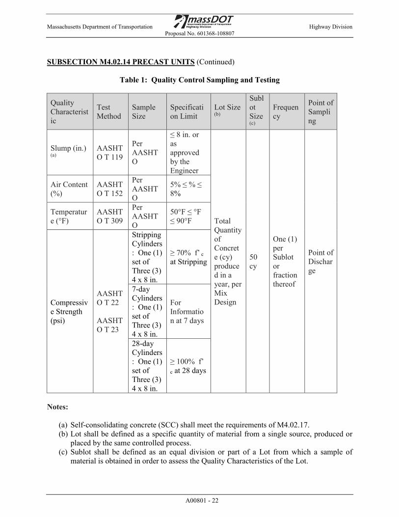
6. Sampling and Testing. At a minimum, the Fabricator shall perform random Quality Control sampling and testing for
each Sublot of concrete produced as specified in Table 1: Quality Control Sampling and Testing. The Fabricator shall perform additional Quality Control sampling and testing on concrete that has been retempered with admixtures or hold-back water during fabrication. Test specimens shall conform to the requirements of Subsection M4.02.13 and AASHTO R 60.
Massachusetts Department of Transportation Highway Division Proposal No. 601368-108807
A00801 - 22
SUBSECTION M4.02.14 PRECAST UNITS (Continued)
Table 1: Quality Control Sampling and Testing
Quality Characteristic
Test Method
Sample Size
Specification Limit
Lot Size (b)
Sublot Size (c)
Frequency
Point of Sampling
Slump (in.) (a)
AASHTO T 119
Per AASHTO
≤ 8 in. or as approved by the Engineer
Total Quantity of Concrete (cy) produced in a year, per Mix Design
50 cy
One (1) per Sublot or fraction thereof
Point of Discharge
Air Content (%)
AASHTO T 152
Per AASHTO
5% ≤ % ≤ 8%
Temperature (°F)
AASHTO T 309
Per AASHTO
50°F ≤ °F ≤ 90°F
Compressive Strength (psi)
AASHTO T 22 AASHTO T 23
Stripping Cylinders: One (1) set of Three (3) 4 x 8 in.
≥ 70% f’ c at Stripping
7-day Cylinders: One (1) set of Three (3) 4 x 8 in.
For Information at 7 days
28-day Cylinders: One (1) set of Three (3) 4 x 8 in.
≥ 100% f’
c at 28 days
Notes:
(a) Self-consolidating concrete (SCC) shall meet the requirements of M4.02.17. (b) Lot shall be defined as a specific quantity of material from a single source, produced or
placed by the same controlled process. (c) Sublot shall be defined as an equal division or part of a Lot from which a sample of
material is obtained in order to assess the Quality Characteristics of the Lot.
Massachusetts Department of Transportation Highway Division Proposal No. 601368-108807
A00801 - 23
SUBSECTION M4.02.14 PRECAST UNITS (Continued)
7. Certificate of Compliance. The Fabricator shall provide a Certificate of Compliance in accordance with Standard
Specifications, Division I, Subsection 6.01, stating that QC test cylinders have achieved the design strength, f’c. A Certificate of Compliance shall accompany each shipment and shall be presented to the MassDOT Resident Engineer or designee upon delivery to the site.
8. Documentation. At a minimum, the Fabricator shall maintain a filing system for the following QC records and
documentation. All QC records and documentation shall be made available to MassDOT upon the request of the Department.
(a) Current MassDOT Approved Mix Design Sheet(s) and Approval Letter(s) (b) PCI or NPCA Certification (c) Current Qualifications and Certifications for QC Manager(s) and QC Technician(s) (d) Most current set of MassDOT Standard Shop Drawings (e) Fabricator Certificate of Compliance for each fabricated Precast Concrete Highway Unit (f) Admixture Manufacturer’s Certification of Compliance and Technical Data Sheet for
each approved Admixture (g) Completed QC Inspection Checklist for each fabricated Precast Concrete Highway Unit (h) Identification Number for each fabricated Precast Concrete Highway Unit (i) Time and date of casting of each fabricated Precast Concrete Highway Unit (j) Date of stripping the forms of each fabricated Precast Concrete Highway Unit (k) Batch Ticket Printout reporting the quantity of concrete produced for each batch of
concrete produced (l) QC Test Report Forms for each sublot of concrete produced (m) Non-Conformance Reports (NCRs) (n) Documentation of Repairs (if applicable)
D. Acceptance. MassDOT will perform Acceptance inspection, sampling, and testing during fabrication and
installation, to evaluate the quality and degree of compliance of the fabricated Precast Concrete Highway Unit to MassDOT specifications. Additionally, MassDOT Inspectors will monitor the Fabricator’s Quality Control activities to ensure the Fabricator is properly administering Quality Control in conformance with the Fabricator’s NPCA or PCI Certification. Acceptance inspection and test results not meeting MassDOT specifications will result in Non-conformance Reports (NCR) being issued by MassDOT to the Fabricator or Contractor for corrective action. Final Acceptance for the fabricated Precast Concrete Highway Units shall be determined by MassDOT.

Massachusetts Department of Transportation Highway Division Proposal No. 601368-108807
A00801 - 24
SUBSECTION M4.02.14 PRECAST UNITS (Continued)
1. Inspection. A MassDOT Inspector may be assigned to perform Acceptance activities during the
fabrication of the Precast Concrete Highway Products, which includes the inspection of the materials, work procedures, and Precast Concrete Highway Units. When a MassDOT Inspector is assigned to the Fabricator’s plant, at least seven (7) days prior to the scheduled start of fabrication, the Fabricator shall contact the MassDOT Research and Materials Section (RMS) to provide notice of the scheduled start date. The Fabricator shall perform the following activites prior to notifying MassDOT RMS of the scheduled start date:
(a) Receive approval for all submitted Fabricator cement concrete mix designs from the
MassDOT Research and Materials Section for the current year, as specified under the Mix Design section and Table 3: Trial Batch Sampling Testing for New Mix Designs. Self-consolidating concrete shall meet the requirements of M4.02.17.
Prior to the start of fabrication, the Fabricator shall review the fabrication schedule with the
MassDOT Inspector. Fabrication shall only proceed when: (a) The QC Inspector and MassDOT Inspector are present to inspect the Precast Concrete
Highway Unit(s) being fabricated. (b) The QC Manager is present at the Fabricator’s plant. The Fabricator shall grant access to all required areas of the Fabricator’s plant to the
MassDOT Inspector, during the hours of fabrication. Fabrication without MassDOT Inspector access to required areas is prohibited, and will result in the rejection of the fabricated Precast Concrete Highway Unit(s). Additionally, the MassDOT Inspector will monitor the adequacy of the Fabricator’s Quality Control activities. MassDOT Inspector Acceptance activities performed at the Fabricator’s plant shall remain independent from the Fabricator, and does not replace the Fabricator’s required Quality Control activities.
2. Sampling and Testing. At a minimum, the MassDOT Inspector will perform random Acceptance sampling and
testing for each Sublot of concrete produced as specified in Table 2: Acceptance Sampling and Testing. The MassDOT Inspector will also perform Acceptance sampling and testing on concrete that has been retempered with admixtures or hold-back water during production. Test Specimens will conform to the requirements of Section M4.02.13 of the MassDOT Standard and Supplemental Specifications and AASHTO R 60.
Massachusetts Department of Transportation Highway Division Proposal No. 601368-108807
A00801 - 25
SUBSECTION M4.02.14 PRECAST UNITS (Continued)
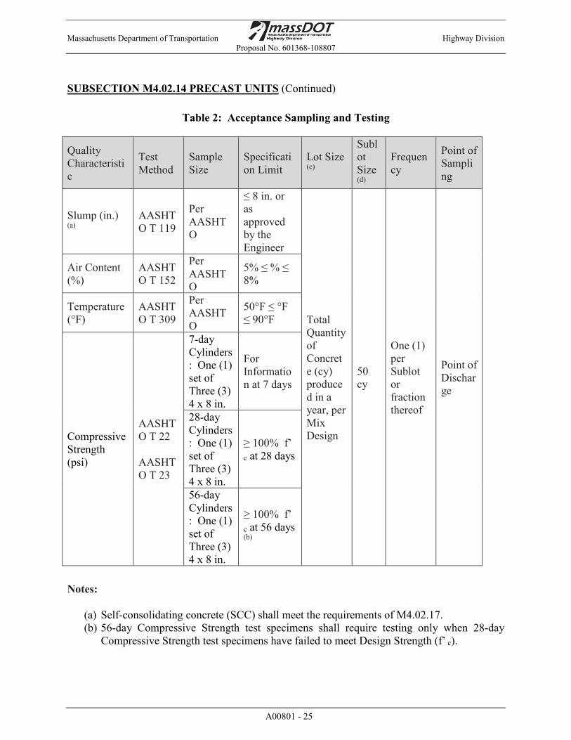
Table 2: Acceptance Sampling and Testing
Quality Characteristic
Test Method
Sample Size
Specification Limit
Lot Size (c)
Sublot Size (d)
Frequency
Point of Sampling
Slump (in.) (a)
AASHTO T 119
Per AASHTO
≤ 8 in. or as approved by the Engineer
Total Quantity of Concrete (cy) produced in a year, per Mix Design
50 cy
One (1) per Sublot or fraction thereof
Point of Discharge
Air Content (%)
AASHTO T 152
Per AASHTO
5% ≤ % ≤ 8%
Temperature (°F)
AASHTO T 309
Per AASHTO
50°F ≤ °F ≤ 90°F
Compressive Strength (psi)
AASHTO T 22 AASHTO T 23
7-day Cylinders: One (1) set of Three (3) 4 x 8 in.
For Information at 7 days
28-day Cylinders: One (1) set of Three (3) 4 x 8 in.
≥ 100% f’
c at 28 days
56-day Cylinders: One (1) set of Three (3) 4 x 8 in.
≥ 100% f’
c at 56 days (b)
Notes:
(a) Self-consolidating concrete (SCC) shall meet the requirements of M4.02.17. (b) 56-day Compressive Strength test specimens shall require testing only when 28-day
Compressive Strength test specimens have failed to meet Design Strength (f’ c).

Massachusetts Department of Transportation Highway Division Proposal No. 601368-108807
A00801 - 26
SUBSECTION M4.02.14 PRECAST UNITS (Continued)
(c) Lot shall be defined as a specific quantity of material from a single source, produced or placed by the same controlled process.
(d) Sublot shall be defined as an equal division or part of a Lot from which a sample of material is obtained in order to assess the Quality Characteristics of the Lot.
MATERIALS
E. Materials. Materials shall meet the following specifications, where applicable: General M4.00.00 Portland Cement M4.01.0 Blended Hydraulic Cements M4.01.1 Fly Ash M4.01.2 Cement Concrete M4.02.00 Cement M4.02.01 Aggregates M4.02.02 Lightweight Aggregates M4.02.03 Water M4.02.04 Cement Concrete Additives M4.02.05 Proportioning M4.02.06 Mixing and Delivery M4.02.10 Test Specimens M4.02.13 Self-Consolidating Concrete (SCC) M4.02.17 Slag AASHTO M-302 High Performance Cement Concrete M4.06.1 Reinforcing Bars M8.01.0 Epoxy Coated Reinforcing Bars M8.01.7 Asphalt Emulsions M3.03.0 1. Cement Concrete Mix Design. Cement concrete for Precast Concrete Highway Units shall meet the requirements of
M4.02.0. When used, High Performance Cement Concrete shall meet the requirements of M4.06.1 and self-consolidating concrete (SCC) shall meet the requirements of M4.02.17. The cement concrete shall be composed of specified proportions by the mass of aggregates, cement, supplementary cementitious materials (SCMs), water, and QCML approved admixtures to form a homogenous composition. The particular quantities and uniform combination of materials and sources of supply to be used by the Fabricator on MassDOT Highway Construction contracts shall be reported on the MassDOT Cement Concrete Mix Design Sheet and submitted to MassDOT RMS for review and approval. All mix design yields shall be designed for 1.0 cubic yards of concrete, with an allowable tolerance of +/- 1.0 %. All liquids incorporated into the proposed mix design(s) shall include both water and admixtures in the liquid mass calculation.

Massachusetts Department of Transportation Highway Division Proposal No. 601368-108807
A00801 - 27
SUBSECTION M4.02.14 PRECAST UNITS (Continued)
Prior to the production and placement of the cement concrete for Precast Concrete Highway
Units, the Fabricator’s proposed mix design shall be approved by MassDOT RMS. Modifications made to the aggregate, cement, supplementary cementitious materials (SCMs), admixtures (including coloring agents), or formulation to previously approved mix designs during fabrication are prohibited. All new mix design formulations and modifications made to previously approved mix designs will require resubmission of the Cement Concrete Mix Design Sheet to MassDOT RMS for review and trial batch testing for the new mix design(s) by the Fabricator. The Fabricator shall notify MassDOT RMS to schedule trial batch testing for the new mix design(s). Trial batch testing shall meet the following requirements:
(a) Performed by a qualified laboratory and/or AASHTO accredited laboratory. (b) Performed and/or sampled in the presence of a MassDOT Inspector. (c) Meet the requirements as specified in Table 3: Trial Batch Sampling Testing for New
Mix Designs. Self-consolidating concrete (SCC) shall meet M4.02.17. Failure to perform all of the required trial batch testing or provide MassDOT RMS trial batch
test results within the Specification Limits (as specified in Table 3) will result in the disqualification of the Fabricator’s proposed mix design(s).
Table 3: Trial Batch Sampling and Testing for New Mix Designs
Quality Characteristic Test Method Sample Size Specification Limit Performed
By
Slump (a) AASHTO T 119 Per AASHTO
Max. 8 inches or as approved by the Engineer
Quality Control
Air Content (AC)
AASHTO T 152 Per AASHTO 5% ≤ AC ≤ 8% Quality
Control Temperature (°F)
AASHTO T 309 Per AASHTO 50°F ≤ °F ≤ 90°F Quality
Control
Compressive Strength (b)
AASHTO T 22 AASHTO T 23
28-day Cylinders: One (1) set of Three (3) 4 x 8 in.
Lab Mixed: 130% f’c at 28 days
MassDOT Batch Mixed: 120% f’c at 28 days
Alkali-Silica Reaction (ASR) (c)
ASTM C 1567 Per ASTM M4.02.00 Quality Control
Resistance to Chloride Ion Penetration (d)
AASHTO T 358 (e)
28-day Cylinders: One (1) set of Three (3) 4 x 8 in.
Resistivity ≥ 15 kΩ-cm at 28 days MassDOT

Massachusetts Department of Transportation Highway Division Proposal No. 601368-108807
A00801 - 28
SUBSECTION M4.02.14 PRECAST UNITS (Continued) Notes:
(a) Self-consolidating concrete (SCC) shall meet the requirements of M4.02.17. (b) Trial batch compressive strength testing shall be performed by MassDOT. Cylinders
shall be haLaboratory mixed trial batch compressive strength results shall achieve 130% Design Strength (f’c). Batch mixed trial batch compressive results shall achieve 120% f’c. Acceptance will be based on compressive strength testing performed by MassDOT.
(c) Alkali Silica Reaction (ASR) testing shall meet the requirements of M4.02.00. Independent laboratories performing ASR testing shall be listed on the MassDOT Quality Construction Materials List (QCML).
(d) Resistance to Chloride Ion Penetration testing shall be performed only on proposed High Performance Cement Concrete mix designs. The calcium nitrite shall be removed from mix designs containing the admixture and replaced by an equivalent quantity of water when preparing Chloride Ion Penetration resistance trial batch test specimens.
(e) The Wenner probe tip spacing “a” shall be 1.5.
CONSTRUCTION METHODS – PLANT FABRICATION
F. Shop Drawings. Fabricator shop drawings for Precast Concrete Highway Units shall conform with the
MassDOT Construction Standard Details, Traffic Standard Drawings for Traffic Signals and Highway Lighting, Overhead Signal Structure and Foundation Standard Drawings, and Standard Drawings for Signs and Supports. Circular vertical precast reinforced concrete manholes and structures used in sewer, drainage, and water works shall conform with the requirements of AASHTO M 199.
G. Tolerances. Precast unit tolerances shall be as indicated on the plans, as specified in Subsection 901, or as
indicated in the MassDOT Construction Standard Details, as appropriate. H. Forms. Concrete shall be cast in rigidly constructed forms, which will maintain the Precast Concrete
Highway Units within specified tolerances to the shapes, lines and dimensions shown on the MassDOT Construction Standard Details. Forms shall be constructed from flat, smooth, non-absorbent material and shall be sufficiently tight to prevent the leakage of the plastic concrete. When wood forms are used, all faces in contact with the concrete shall be laminated or coated with a non-absorbent material. All worn or damaged forms, which cause irregularities on the concrete surface or damage to the concrete during form removal, shall be repaired or replaced before being reused. Any defects or damage of more than minor nature, due to form work, stripping or handling, shall be cause for rejection, as defined in Repairs and Replacement, unless approved for repair through the NCR process. If threaded inserts are cast into the elements for support of formwork, the inserts shall be recessed a minimum of 1 inch and shall be plugged after use with a grout of the same color as that of the precast cement concrete.
Massachusetts Department of Transportation Highway Division Proposal No. 601368-108807
A00801 - 29
SUBSECTION M4.02.14 PRECAST UNITS (Continued)
I. Mixing of Concrete. The concrete shall be proportioned and mixed in conformance with the Fabricator’s
MassDOT approved mix design and M4.02.10 Mixing and Delivery. Fabrication shall not occur without a MassDOT approved mix design. The Fabricator shall provide copies of batch tickets to the MassDOT Plant Inspector. The MassDOT Plant Inspector will verify if the batch ticket quantities are within the tolerances of the Fabricator’s MassDOT approved mix design.
J. Placement of Concrete. Prior to the placement of concrete, the temperature of the forms shall be greater than or equal
to 50°F. Quality Control inspection shall be performed by the Fabricator as specified in the Fabricator Quality Control section. The Quality Control Inspector shall inspect and accept the placement of the reinforcing steel prior to the placement of concrete into the forms. When a MassDOT Inspector is assigned to perform Acceptance activities at the Fabricator’s facility, placement of the concrete shall not proceed until the MassDOT Plant Inspector is present to perform inspection and begin monitoring Fabricator Quality Control inspection activities, and is in compliance with specifications. The MassDOT Plant Inspector shall inspect and accept the placement of the reinforcing steel prior to the placement of concrete into the forms. The Fabricator shall verify all materials and equipment required for protecting and curing the concrete are readily available and meet the requirements of the Final Curing Methods section below. All items encased in the concrete shall be accurately placed in the position shown on the Plans and firmly held during the placing and setting of the concrete. Clearance from the forms shall be maintained by supports, spacers, or hangers and shall be of approved shape and dimension.
During placement, the concrete shall maintain a concrete temperature range between 50°F and 90°F. The Fabricator shall minimize the time to concrete placement (measured from start of mixing to completion of placement). In no event shall time to placement exceed 90 minutes. The Fabricator shall perform additional Quality Control sampling and testing on concrete that has been retempered with admixtures or hold-back water during the placement of the concrete as specified in the Fabricator Quality Control section above. Delays or shutdowns of over 30 minutes shall not be allowed during the continuous filling of individual forms.
K. Consolidation of Concrete. Suitable means shall be used for placing concrete to prevent segregation or displacement of
reinforcing steel or forms. The concrete shall be thoroughly consolidated by external or internal vibrators or a combination of both. Vibrators shall not be used to move concrete within the forms. Vibrators shall be used as specified in 901.63C and as directed by the Engineer. Concrete shall be placed and consolidated in a way that minimizes the presence of surface voids or bug holes on the formed surfaces. When used, self-consolidating concrete (SCC) shall meet the requirements of M4.02.17.
L. Exposed Surfaces of Precast Concrete Highway Units. As soon as conditions permit and before the concrete has fully hardened; all dirt, laitance,
and loose aggregate shall be removed from the exposed concrete surfaces. Contractor shall not allow foot traffic on the uncured concrete until it has reached sufficient strength to prevent damage.

Massachusetts Department of Transportation Highway Division Proposal No. 601368-108807
A00801 - 30
SUBSECTION M4.02.14 PRECAST UNITS (Continued)
M. Final Curing Methods. All exposed concrete surfaces shall meet the requirements of the selected final curing method
and maintain the required concrete temperature ranges throughout the duration of the final curing method cycle. Controlled and gradual termination of the final curing method cycle shall occur after all the specified conditions are met.
1. Water Spray Curing. The final curing method cycle shall begin immediately after the concrete has hardened
sufficiently to prevent surface damage from the water spray. After the concrete has sufficiently hardened, all exposed concrete surfaces shall remain moist with a continuous fine spray of water throughout the entire duration of the final curing method cycle. Controlled and gradual termination of the final curing method cycle shall occur after all specified conditions are met (see Table 4: Termination of Curing Cycle for Water Spray Curing).
Table 4: Termination of Curing Cycle for Water Spray
Sustained Ambient Temperature
Compressive Strength
50°F ≤ °F ≤ 90°F ≥ 70% f’c
2. Saturated Covers for Curing. The final curing method cycle shall begin immediately after the concrete has hardened
sufficiently to prevent surface damage from the saturated burlap. After the concrete has sufficiently hardened, all exposed concrete surfaces shall be covered with water-saturated burlap throughout the entire duration of the final curing method cycle. Controlled and gradual termination of the final curing method cycle shall occur after all specified conditions are met (see Table 5: Termination of Curing Cycle for Saturated Cover Curing).
Table 5: Termination of Curing Cycle for Saturated Covers
Sustained Ambient Temperature
Compressive Strength
50°F ≤ °F ≤ 90°F ≥ 70% f’c
Massachusetts Department of Transportation Highway Division Proposal No. 601368-108807
A00801 - 31
SUBSECTION M4.02.14 PRECAST UNITS (Continued)
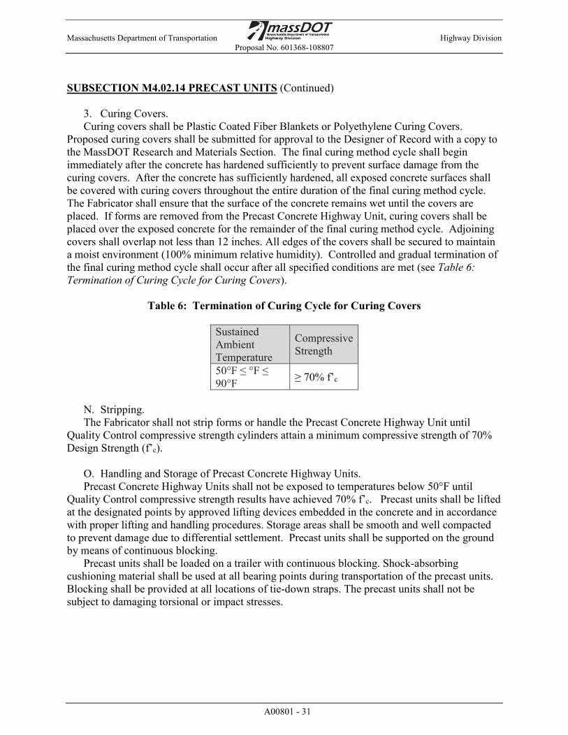
3. Curing Covers. Curing covers shall be Plastic Coated Fiber Blankets or Polyethylene Curing Covers.
Proposed curing covers shall be submitted for approval to the Designer of Record with a copy to the MassDOT Research and Materials Section. The final curing method cycle shall begin immediately after the concrete has hardened sufficiently to prevent surface damage from the curing covers. After the concrete has sufficiently hardened, all exposed concrete surfaces shall be covered with curing covers throughout the entire duration of the final curing method cycle. The Fabricator shall ensure that the surface of the concrete remains wet until the covers are placed. If forms are removed from the Precast Concrete Highway Unit, curing covers shall be placed over the exposed concrete for the remainder of the final curing method cycle. Adjoining covers shall overlap not less than 12 inches. All edges of the covers shall be secured to maintain a moist environment (100% minimum relative humidity). Controlled and gradual termination of the final curing method cycle shall occur after all specified conditions are met (see Table 6: Termination of Curing Cycle for Curing Covers).
Table 6: Termination of Curing Cycle for Curing Covers
Sustained Ambient Temperature
Compressive Strength
50°F ≤ °F ≤ 90°F ≥ 70% f’c
N. Stripping. The Fabricator shall not strip forms or handle the Precast Concrete Highway Unit until
Quality Control compressive strength cylinders attain a minimum compressive strength of 70% Design Strength (f’c).
O. Handling and Storage of Precast Concrete Highway Units. Precast Concrete Highway Units shall not be exposed to temperatures below 50°F until
Quality Control compressive strength results have achieved 70% f’c. Precast units shall be lifted at the designated points by approved lifting devices embedded in the concrete and in accordance with proper lifting and handling procedures. Storage areas shall be smooth and well compacted to prevent damage due to differential settlement. Precast units shall be supported on the ground by means of continuous blocking.
Precast units shall be loaded on a trailer with continuous blocking. Shock-absorbing cushioning material shall be used at all bearing points during transportation of the precast units. Blocking shall be provided at all locations of tie-down straps. The precast units shall not be subject to damaging torsional or impact stresses.
Massachusetts Department of Transportation Highway Division Proposal No. 601368-108807
A00801 - 32
SUBSECTION M4.02.14 PRECAST UNITS (Continued)
P. Repairs and Replacement (not including Proprietary Retaining Wall Systems) Where noted, defects shall be repaired according to the PCI Northeast Region Guidelines for
Resolution of Non-Conformances in Precast Concrete Highway Units, Report Number PCINE-18-RNPCBE. Please note that reference to PCINE-18-RNPCBE is made for repair details only. In the case of conflict with this specification, this specification shall govern.
Any required repairs shall utilize materials listed on the MassDOT QCML. All repairs shall be completed at the expense of the Contractor.
Q. Repairs and Replacement for Proprietary Retaining Wall Systems. In the event defects are identified, they shall be classified in the following categories and a
non-conformance report (NCR) shall be filed if required. The NCR shall be submitted to MassDOT for review. Defects in all categories shall be documented by plant Quality Control personnel and made available to MassDOT upon request. Any required repairs shall utilize materials listed on the MassDOT QCML.
1. Category 1, Surface Defects. Category 1 defects do not need to be repaired, and an NCR does not need to be filed. Surface
defects are defined as:
(a) Surface voids or bug holes that are less than 5/8-inch in diameter and less than ¼-inch deep, except when classified as Category 3
(b) cracks less than or equal to 0.006” wide
2. Category 2, Minor Defects. Category 2 defects shall be repaired and documented. Non-conformance Reports are not
required for this category. Documentation of the repair shall be submitted to the MassDOT District Engineer. Minor defects are defined as:
(a) Spalls, honeycombing, surface voids that are less than 2 inches deep and have no
dimension greater than 12 inches (b) Cracks greater than 0.006” and less than or equal to 0.060” (c) Broken corners without exposed reinforcing steel
Defects and cracks shall be repaired according to the Guidelines for Resolution of Non-
Conformances in Precast Concrete Highway Units, Report Number PCINE-18-RNPCBE and this specification. All repairs shall be completed at the expense of the Contractor. Any required repairs shall utilize materials listed on the MassDOT QCML.
Massachusetts Department of Transportation Highway Division Proposal No. 601368-108807
A00801 - 33
SUBSECTION M4.02.14 PRECAST UNITS (Continued)
3. Category 3, Rejectable Defects. Rejectable defects as determined by the MassDOT Inspector and MassDOT Resident
Engineer will be rejected, unless the Fabricator receives MassDOT approval of a Non-Conformance Report. Some rejectable defects are defined as:
(a) Surface defects on more than 5% of the surface area (b) Minor defects that in total make up more than 5% of the surface area of the unit (c) Concentrated area of defects consisting of four or more Category 2 Defects within a 4-
square foot area. (d) Exposed reinforcing steel (e) Spalls, honeycombing and surface voids that are deeper than 2 inches or have any
dimension greater than 12 inches, when measured along a straight line (f) Cracks greater than 0.060” in width (g) Elements fabricated outside of the specified tolerances (h) Compressive strength that does not meet the specified Design Strength, f’c
R. Loading. Prior to the Fabricator loading the Precast Concrete Highway Unit on to the truck for
shipping, the Fabricator shall provide the MassDOT Plant Inspector and RMS a minimum seven (7) days’ notice of the Fabricator’s intent to load the Precast Concrete Highway Unit. Inspection by the MassDOT Plant Inspector shall take place while the element is still on dunnage in the yard. The element shall not be loaded onto the truck until the MassDOT Plant Inspector has performed the inspection.
S. Shipping. Prior to shipment, the Fabricator shall perform the following actions and provide the required
documentation to the MassDOT Plant Inspector: (a) Precast Concrete Highway Units shall remain at the Fabricator’s plant for a minimum of
7 days after cast date. (b) QC Inspection Reports shall be signed by the Quality Control Manager and provided to
the MassDOT Plant Inspector. (c) QC Compressive Strength Test Report Forms attaining Design Strength, f’c for the
Precast Concrete Highway Unit’s representative Sublot shall be generated by the Fabricator and provided to the MassDOT Plant Inspector.
(d) Certificate of Compliance shall be generated by the Fabricator as described under the Fabricator Quality Control section and provided to the MassDOT Plant Inspector.
(e) All MassDOT RMS approved Corrective Actions submitted on the Non-Conformance Reports (NCR), shall be verified to have been completed by the MassDOT Plant Inspector and Quality Control Manager.
(f) All NCRs shall be signed off by the Quality Control Manager and MassDOT Inspector and/or MassDOT RMS.
Massachusetts Department of Transportation Highway Division Proposal No. 601368-108807
A00801 - 34
SUBSECTION M4.02.14 PRECAST UNITS (Continued)
T. Delivery. Upon Delivery, the following documentation shall be provided to the MassDOT Resident
Engineer or designee: (a) QC Compressive Strength Test Report Forms attaining Design Strength, f’c for the
Precast Concrete Highway Unit’s representative Sublot. (b) Certificate of Compliance generated by the Fabricator as described under the Fabricator
Quality Control section. (c) QC Inspection Reports signed by the Quality Control Manager.
The Contractor shall inspect Precast Concrete Highway Units upon receipt at the site. Precast
Concrete Highway Units damaged during delivery shall be repaired or replaced at MassDOT’s direction at no cost to MassDOT..
Massachusetts Department of Transportation Highway Division Proposal No. 601368-108807
A00801 - 35
SUBSECTION 8.14 UTILITY COORDINATION, DOCUMENTATION, AND MONITORING RESPONSIBILITIES A. GENERAL In accordance with the provisions of Section 8.00 Prosecution and Progress, utility coordination is a critical aspect to this Contract. This section defines the responsibility of the Contractor and MassDOT, with regard to the initial utility relocation plan and changes that occur as the prosecution of the Work progresses. The Engineer, with assistance from the Contractor shall coordinate with Utility companies that are impacted by the Contractor’s operations. To support this effort, the Contractor shall provide routine and accurate schedule updates, provide notification of delays, and provide documentation of the steps taken to resolve any conflicts for the temporary and/or permanent relocations of the impacted utilities. The Contractor shall provide copies to the Engineer of the Contractor communication with the Utility companies, including but not limited to: • Providing advanced notice, for all utility-related meetings initiated by the Contractor. • Providing meeting minutes for all utility-related meetings that the Contractor attends. • Providing all test pit records. • Request for Early Utility work requirements of this section (see below). • Notification letters for any proposed changes to Utility start dates and/or sequencing. • Written notification to the Engineer of all apparent utility delays within seven (7) Calendar
Days after a recognized delay to actual work in the field – either caused by a Utility or the Contractor.
• Any communication, initiated by the Contractor, associated with additional Right-of-Way needs in support of utility work.
• Submission of completed Utility Completion Forms. B. PROJECT UTILITY COORDINATION (PUC) FORM The utility schedule and sequence information provided in the Project Utility Coordination Form (if applicable) is the best available information at the time of the bid and has been considered in setting the contract duration. The Contractor shall use all of this information in developing the bid price and the Baseline Schedule Submission, inclusive of the individual utility durations sequencing requirements, and any work that has been noted as potentially concurrent utility installations. C. INITIATION OF UTILITY WORK The Engineer will issue all initial notice-to-proceed dates to each Utility company based on either the: 1) Contractor’s accepted Baseline Schedule 2) An approved Early Utility Request in the form of an Early Utility sub-net schedule (in
accordance with the requirements of this Subsection) 3) An approved Proposal Schedule

Massachusetts Department of Transportation Highway Division Proposal No. 601368-108807
A00801 - 36
SUBSECTION 8.14 (Continued) C.1 - BASELINE SCHEDULE – UTILITY BASIS The Contractor shall provide a Baseline Schedule submission in accordance with the requirements of Subsection 8.02 and inclusive of all of the information provided in the PUC Form that has been issued in the Contract documents. This is to include the utility durations, sequencing of work, allowable concurrent work, and all applicable considerations that have been depicted on the PUC Form. C.2 – EARLY UTLITY REQUEST – (aka SUBNET SCHEDULE) PRIOR TO THE BASELINE All early utility work is defined as any anticipated/required utility relocations that need to occur prior to the Baseline Schedule acceptance. In all cases of proposed early utility relocation, the Contractor shall present all known information at the pre-construction conference in the form of a ‘sub-net’ schedule showing when each early utility activity needs to be issued a notice-to-proceed. The Contractor shall provide advance notification of this intent to request early utility work in writing at or prior to the Pre-Construction meeting. Prior to officially requesting approval for early utility work, the Contractor shall also coordinate with MassDOT and all utility companies (private, state or municipal) which may be impacted by the Contract. If this request is acceptable to the Utilities and to MassDOT, the Engineer will issue a notice-to-proceed to the affected Utilities, based on these accepted dates. C.3 – PROPOSAL SCHEDULE - CHANGES TO THE PUC FORM If the Contractor intends to submit a schedule (in accordance with MassDOT Standard Specifications, Division I, Subsection 8.02) that contains durations or sequencing that vary from those provided in the Project Utility Coordination (PUC) Form, the Contactor must submit this as an intended change, in the form of a Proposal Schedule and in accordance with MassDOT Standard Specifications, Division I, Subsection 8.02. These proposed changes are subject to the approval of the Engineer and the impacted utilities, in the form of this Proposal Schedule and a proposed revision to the PUC form. The Contractor shall not proceed with any changes of this type without written authorization from the Engineer, that references the approved Proposal Schedule and PUC form changes. The submission of the Baseline Schedule should not include any of these types of proposed utility changes and should not delay the submission of the Baseline Schedule. As a prerequisite to the Proposal Schedule submission, and in advance of the utility notification(s) period, the Contractor shall coordinate the proposed utility changes with the Engineer and the utility companies, to develop a mutually agreed upon schedule, prior to the start of construction.

Massachusetts Department of Transportation Highway Division Proposal No. 601368-108807
A00801 - 37
SUBSECTION 8.14 (Continued) D. UTILITY DELAYS The Contractor shall notify the Engineer upon becoming aware that a Utility owner is not advancing the work in accordance with the approved utility schedule. Such notice shall be provided to the Engineer no later than seven (7) calendar days after the occurrence of the event that the Contractor believes to be a utility delay. After such notice, the Engineer and the Contractor shall continue to diligently seek the Utility Owner’s cooperation in performing their scope of Work. In order to demonstrate that a critical path delay has been caused by a third-party Utility, the Contractor must demonstrate, through the requirements of the monthly Progress Schedule submissions and the supporting contract records associated with Subsection 8.02, 8.10 and 8.14, that the delays were beyond the control of the Contractor. All documentation provided in this section is subject to the review and verification of the Engineer and, if required, the Utility Owner. In accordance with MassDOT Specifications, Division I, Subsection 8.10, a Time Extension will be granted for a delay caused by a Utility, only if the actual duration of the utility work is in excess of that shown on the Project Utility Coordination Form, and only if; 1) proper Notification of Delay was provided to MassDOT in accordance with the time
requirements that are specified in this Section 2) the utility delay is a critical path impact to the Baseline Schedule (or most recently approved
Progress Schedule) E. LOCATION OF UTILITIES The locations of existing utilities are shown on the Contract drawings as an approximation only. The Contractor shall perform a pre-construction utility survey, including any required test pits, to determine the location of all known utilities no later than thirty (30) calendar days before commencing physical site work in the affected area. F. POST UTILITY SURVEY – NOTIFICATION Following completion of a utility survey of existing locations, the Contractor will be responsible to notify the Engineer of any known conflicts associated with the actual location of utilities prior to the start of the work. The Engineer and the Contractor will coordinate with any utility whose assets are to be affected by the Work of this Contract. A partial list of utility contact information is provided in the Project Utility Coordination Form.

Massachusetts Department of Transportation Highway Division Proposal No. 601368-108807
A00801 - 38
SUBSECTION 8.14 (Continued) G. MEETINGS AND COOPERATION WITH UTILITY OWNERS The Contractor shall notify the Engineer in advance of any meeting they initiate with a Utility Owner’s representative to allow MassDOT to participate in the meeting if needed. Prior to the Pre-Construction Meeting, the Contractor should meet with all Utility Owners who will be required to perform utility relocations within the first 6 months of the project, to update the affected utilities of the Project Utility Coordination Form and all other applicable Contract requirements that impact the Utilities. The Contractor shall copy the Engineer on any correspondence between the Utility Owner and the Contractor. H. FORCE ACCOUNT / UTILITY MONITORING REQUIREMENTS The Engineer will be responsible for recording daily Utility work force reports. The start, suspension, re-start, and completion dates of each of the Utilities, within each phase of the utility relocation work, will be monitored and agreed to by the Engineer and the Contractor as the work progresses. I. ACCESS AND INSPECTION The Contractor shall be responsible for allowing Utility owners access to their own utilities to perform the relocations and/or inspections. The Contractor shall schedule their work accordingly so as not to delay or prevent each utility from maintaining their relocation schedule.

Massachusetts Department of Transportation Highway Division Proposal No. 601368-108807
A00801 - 39
SECTION 722 CONSTRUCTION SCHEDULING
DESCRIPTION
722.20 General
The Contractor's approach to prosecution of the Work shall be disclosed to the Department by submission of a Critical Path Method (CPM) schedule and a cost/resource loaded Construction Schedule when required in this Subsection. These requirements are in addition to, and not in limitation of, requirements imposed in other sections.
The requirements for scheduling submissions are established based on the Project Value at the time of the bid and are designated as Type A, B, C or D. The definitions of these Schedule Requirement Types are summarized below. Complete descriptions of all detailed requirements are established elsewhere in this specification. Type A – for all Site-Specific Contracts with a Project Value over $20 Million
• Schedule Planning Session • Baseline CPM Schedule • Monthly Update CPM Schedule • Short-term Construction Schedule • Contract Schedule Update Meeting • Resource-Loading • Resources Graphic Reporting • Cash Flow Projections from the CPM • Cash Flow Charts • Cost-loaded CPM • Contractor-furnished CPM software, computer and training
Type B – for all Site-Specific Contracts with a Project Value between $10 Million and $20 Million
• Schedule Planning Session • Baseline CPM Schedule • Monthly Update CPM Schedule • Short-term Construction Schedule • Contract Schedule Update Meeting • Cost-loaded CPM • Resource-Loading • Monthly Projected Spending Report (PSR) • Contractor-furnished CPM software, computer and training
Massachusetts Department of Transportation Highway Division Proposal No. 601368-108807
A00801 - 40
SECTION 722 (Continued) Type C – for all Site-Specific Contracts with a Project Value between $3 Million and $10 Million
• Schedule Planning Session • Baseline CPM Schedule • Monthly Update CPM Schedule • Short-term Construction Schedule • Contract Schedule Update Meeting • Monthly Projected Spending Report (PSR) • Contractor-furnished CPM software, computer and training
Type D - for all contracts with a Project Value less than $3 Million; various locations contracts of any dollar amount; contracts with durations less than one-hundred and eighty (180) Calendar Days; and other contracts as determined by the Engineer.
• Bar chart schedule updated monthly or at the request of the Engineer (See Section 722.62.B - Bar Charts.)
• Monthly Projected Spending Report (PSR) (See Section 722.62.F - Projected Spending Reports.)
MATERIALS, EQUIPMENT, PERSONNEL
722.40 General
A. Software Requirements (Types A, B and C) The Contractor shall use Primavera P6 computer scheduling software. In addition to the requirements of Section 740 – Engineer’s Field Office and Equipment, the
Contractor shall provide to the Department one (1) copy of the scheduling software, one (1) software license and one (1) computer capable of running the scheduling software for the duration of the Contract. This computer and software shall be installed in the Engineer’s Field Office within twenty-eight (28) Calendar Days after Notice to Proceed. The computer and software shall be maintained and serviced as recommended by the computer manufacturer and/or as required by the Engineer during the duration of the Contract at no additional cost to the Department. The Contractor shall provide professional training in the basic use of the software for up to eight (8) Department employees. The trainer shall be approved by the Engineer. This training shall be provided within twenty-eight (28) Calendar Days after Notice to Proceed.
B. Scheduler Requirements For all schedule types, if the Contractor plans to use outside scheduling services, the
scheduler shall be approved as a subcontractor by the Engineer.
For Type A, B and C Schedules the name of the Contractor’s Project Scheduler together with his/her qualifications shall be submitted to the Department for approval by the Engineer within seven (7) Calendar Days after NTP. The Project Scheduler shall have a minimum of five [5] years of project CPM scheduling experience, three [3] years of which shall be on projects of similar scope and value as the project for which the Project Scheduler is being proposed. References shall be provided from past projects that can attest to the capabilities of the Project Scheduler.
Massachusetts Department of Transportation Highway Division Proposal No. 601368-108807
A00801 - 41
SECTION 722 (Continued)
CONSTRUCTION METHODS 722.60 General
A. Schedule Planning Session (Types A, B and C)
The Contractor shall conduct a schedule planning session within seven (7) Calendar Days
after the Contractor receives the NTP and prior to submission of the Baseline Schedule. This session will be attended by the Department and its consultants. During this session, the Contractor shall present its planned approach to the project including, but not limited to:
1. the Work to be performed by the Contractor and its subcontractors; 2. the planned construction sequence and phasing; planned crew sizes; 3. summary of equipment types, sizes, and numbers to be used for each work activity; 4. all early work related to third party utilities; 5. identification of the most critical submittals and projected submission timelines; 6. estimated durations of major work activities; 7. the anticipated Critical Path of the project and a summary of the activities on that Critical
Path; 8. a summary of the most difficult schedule challenges the Contractor is anticipating and
how it plans to manage and control those challenges; 9. a summary of the anticipated quarterly cash flow over the life of the project.
This will be an interactive session and the Contractor shall answer all questions that the
Department and its consultants may have. The Contractor shall provide a minimum of five (5) copies of a written summary of the information presented and discussed during the session to the Engineer. The Contractor’s Baseline Schedule and accompanying Schedule Narrative shall incorporate the information discussed at this Schedule Planning Session.
B. Schedule Reviews by the Department (All Types)
1. Baseline Schedule Reviews The Engineer will respond to the Baseline Schedule Submission within thirty (30) Calendar Days of receipt providing comments, questions and/or disposition that either accepts the schedule or requires revision and resubmittal. Baseline Schedules shall be resubmitted within fifteen (15) Calendar Days after receipt of the Engineer’s comments.
2. Contract Progress Schedule / Monthly Update Reviews
The Engineer will respond to each submittal within twenty one (21) Calendar Days. Schedules shall be resubmitted by the Contractor within five (5) Calendar Days after receipt of the Engineer’s comments.
Failure to submit schedules as and when required could result in the withholding of full or partial pay estimate payments by the Engineer.
Massachusetts Department of Transportation Highway Division Proposal No. 601368-108807
A00801 - 42
SECTION 722 (Continued) 722.61 Schedule Content and Preparation Requirements
(Types A, B and C unless otherwise noted) Each Contract Progress Schedule shall fully conform to these requirements.
A. LOGIC The schedules shall divide the Work into activities with appropriate logic ties to show:
1. conformance with the requirements of this Section and Division I, Subsection 8.02 - Schedule of Operations
2. the Contractor's overall approach to the planning, scheduling and execution of the Work
3. conformance with any additional sequences of Work required by the Contract Documents, including, but not limited to, Subsection 8.03 - Prosecution of Work and Subsection 8.06 – Limitations of Operations.
B. ACTIVITIES The schedules shall clearly define the progression of the Work from NTP to Contractor Field
Completion (CFC) by using separate activities for each of the following items: 1. NTP 2. Each component of the Work defined by specific activities 3. Detailed activities to satisfy permit requirements 4. Procurement of fabricated materials and equipment with long lead times, including time
for review and approval of submittals required before purchasing 5. The preparation and submission of shop drawings, procedures and other required
submittals, with a planned duration that is to be demonstrated to the Engineer as reasonable
6. The review and return of shop drawings, procedures and other required submittals, approved or with comments, the duration of which shall be thirty (30) Calendar Days, unless otherwise specified or as approved by the Engineer
7. Interfaces with adjacent work, utility companies, other public agencies, sensitive abutters, and/or any other third party work affecting the Contract
8. The Critical Path, clearly defined and organized 9. Float shall be clearly identified 10. Access Restraints – restrictions on access to areas of the Work that are defined by the
Department in the bid package, in Subsection 8.06 – Limitations of Operations or elsewhere in the Contract
11. Milestones listed in Subsection 8.03 - Prosecution of Work or elsewhere in the Contract Documents
12. Subcontractor approvals at fifteen (15) Calendar Days from submittal to response 13. Full Beneficial Use (FBU) Contract Milestone per the requirements of Subsection 8.03
- Prosecution of Work 14. Contractor’s request for validation of FBU (ready to open to traffic) 15. The Department’s confirmation of completed work to allow for FBU

Massachusetts Department of Transportation Highway Division Proposal No. 601368-108807
A00801 - 43
SECTION 722 (Continued)
16. Substantial Completion Contract Milestone per the requirements of Subsections 7.15 - Claims Against Contractors for Payment of Labor, Materials and Other Purposes and 8.03 - Prosecution of Work
17. Contractor’s request for validation of Substantial Completion 18. Punchlist Completion Period of at least thirty (30) Calendar Days per the requirements
of Subsections 5.11 - Final Acceptance, 7.15 - Claims Against Contractors for Payment of Labor, Materials and Other Purposes and 8.03 - Prosecution of Work
19. Contractor confirmation that all punchlist work and documentation has been completed
20. Physical Completion of the Work Contract Milestone per the requirements of Subsections 5.11 - Final Acceptance and 8.03 - Prosecution of Work
21. Documentation Completion per the requirements of Subsections 5.11 - Final Acceptance and 8.03 - Prosecution of Work
22. Contractor Field Completion Contract Milestone per the requirements of Subsections 5.11 - Final Acceptance and 8.03 - Prosecution of Work
23. Utility work to be performed in accordance with the Project Utility Coordination (PUC) Form as provided in Section 8.14 - Utilities Coordination, Documentation and Monitoring Responsibilities
24. Traffic work zone set-up and removal, night work and phasing 25. Early Utility Relocation (by others) that has been identified in the Contract 26. Right-of-Way (ROW) takings that have been identified in the Contract 27. Material Certifications 28. Work Breakdown Structure in accordance with the MassDOT-Highway Division
Contractor Construction Schedule Toolkit located on the MassDOT-Highway Division website at: https://www.mass.gov/info-details/massdot-highway-contractors-schedule-toolkit
29. For Type A and B Contracts only: All items to be paid, including all Unit Price and Lump Sum pay items, shall be identified by activity. This shall include all non-construction activities such as engineering work; purchase of permanent materials and equipment, purchase of structural steel stock, equipment procurement, equipment delivery to the site or storage location and the representative amount of overhead/indirect costs that was included in the Contractor’s Bid Prices.
C. EARLY AND LATE DATES Early Dates shall be based on proceeding with the Work or a designated part of the Work
exactly on the date when the corresponding Contract Time commences. Late Dates shall be based on completing the Work or a designated part of the Work exactly on the corresponding Contract Time, even if the Contractor anticipates early completion.
Massachusetts Department of Transportation Highway Division Proposal No. 601368-108807
A00801 - 44
SECTION 722 (Continued)
D. DURATIONS Activity durations shall be in Work Days. Planned Original Durations shall be established
with consideration to resources and production rates that correspond to the Contractor’s Bid Price. Within all of the Department-required schedules, the Contractor shall plan the Work using durations for all physical construction activities of no less than one (1) Work Day and no greater than fourteen (14) Work Days, unless approved by the Engineer as part of the Baseline Schedule Review.
Should there be an activity with a duration that is determined by the Engineer to be unreasonable, the Contractor will be asked to provide a basis of the duration using bid documents, historic production rates for similar work, or other form of validation that is acceptable to the Engineer. Should the Contractor and the Engineer be unable to agree on reasonable activity durations, the Engineer will, at a minimum, note the disagreement in the Baseline Schedule Review along with a duration the Engineer considers reasonable and the basis for that duration. A schedule that contains a substantial number of activities with durations that are deemed unreasonable by the Engineer will not be accepted.
E. MATERIALS ON HAND (for Types A and B only) The Contractor shall identify in the Baseline Schedule all items of permanent materials
(Materials On Hand) for which the Contractor intends to request payment prior to the incorporation of such items into the Work.
F. ACTIVITY DESCRIPTIONS The Contractor shall use activity descriptions in all schedules that clearly describe the work
to be performed using a combination of words, structure numbers, station numbers, bid item numbers, work breakdown structure (WBS) and/or elevations in a concise and compact label as specified in the MassDOT-Highway Division Contractor Construction Schedule Toolkit located on the MassDOT-Highway Division website at:
https://www.mass.gov/info-details/massdot-highway-contractors-schedule-toolkit
G. ACTIVITY IDENTIFICATION NUMBERS The Contractor shall use the activity identification numbering system specified in the
MassDOT-Highway Division Contractor Construction Schedule Toolkit located online at the address above.
H. ACTIVITY CODES The Contractor shall use the activity codes specified in the MassDOT-Highway Division
Contractor Construction Schedule Toolkit located online at the address above.
I. CALENDARS Different calendars may be created and assigned to all activities or to individual activities.
Calendars define the available hours of work in each Calendar Day, holidays and general or project-specific non-Work Days such as Fish Migration Periods, time of year (TOY) restrictions and/or area roadway restrictions.

Massachusetts Department of Transportation Highway Division Proposal No. 601368-108807
A00801 - 45
SECTION 722 (Continued)
Examples of special calendars include, but are not limited to: • Winter Shutdown Period, specific work is required by separate special provision to be
performed during the winter. See Special Provision 8.03 (if applicable) • Peak traffic hours on heavily traveled roadways. This shall be from 6:30 am to 9:30 am
and from 3:30 pm to 7:00 pm, unless specified differently elsewhere in the Contract. • Special requirements by sensitive abutters, railroads, utilities and/or other state agencies
as defined in the Contract. • Cape Cod and the Islands Summer Roadway Work Restrictions: A general restriction
against highway and bridge construction is enforced between Memorial Day and Labor Day, unless otherwise directed by the Engineer. Refer to the Project Special Provisions for specific restrictions.
• Cape Ann Summer Roadway Work Restrictions: While there are no general restrictions for Cape Ann as there are for Cape Cod and the Islands, project-specific restrictions may be enforced. Refer to the Project Special Provisions for specific restrictions.
• Turtle and/or Fish Migration Periods and/or other in-water work restrictions: Refer to the Project Special Provisions for specific restrictions.
• Working over Waterways Restricted Periods: Refer to the Project Special Provisions for specific restrictions.
• Night-time paving and striping operations, traffic and temperature restrictions: Refer to the Project Special Provisions for specific restrictions.
• Utility Restrictions shall be as specified within the Contract.
J. FLOAT For the calculation of float in the CPM schedule, the setting for Retained Logic is required for
all schedule submissions, starting with the Baseline Schedule Submission. Should the Contractor have a reason to propose that an alternative calculation setting such as Progress Override be used, the Contractor shall obtain the Engineer’s approval prior to modifying to this setting.
K. COST AND RESOURCE LOADING (Types A and B only) For all Type A and B Schedules, the Contractor shall provide a cost and resource-loaded
schedule with an accurate allocation of the costs and resources necessary to complete the Work. The costs and resources shall be assigned to all schedule activities in order to enable the Contractor to efficiently execute the Contract requirements and the Engineer to validate the original plan, monitor progress, provide cash flow projections and analyze delays.
1. Each schedule activity shall have an assigned cost that accurately represents the value of the Work. Each schedule activity shall have its resources assigned to it by craft and the anticipated hours to accomplish the work. Each schedule activity’s equipment resources shall be assigned to it by equipment type and hours operated. Front-loading or other unbalancing of the cost distribution will not be permitted.
2. The sum of the cost of all schedule activities shall be equal to the Contractor’s Bid Price.
3. Indicating the labor hours per individual, per day, by craft and equipment hours/day will be acceptable.

Massachusetts Department of Transportation Highway Division Proposal No. 601368-108807
A00801 - 46
SECTION 722 (Continued)
4. The Engineer reserves the right to use the cost-loading as a means to resolve changes, disputes, time entitlement evaluations, increases or decreases in the scope of Work, unit price renegotiations and/or claims.
5. For all Type A and B Schedules, all subnets, fragnets, Proposal Schedules, and Recovery Schedules shall be cost and resource- loaded to help to quickly validate and monitor the duration of the Work to be performed.
6. For Type A Schedules, cost-loading of the schedule will also be used for cash flow projection purposes.
7. The cost-loading of each activity shall indicate the portion of the cost for that activity that is applicable to a specific bid item (cost account.) The total cost for each cost account must equal the bid item price.
8. For Type A Schedules, each month, the Contractor will be paid using the Cost-loaded CPM activities for Lump Sum payment items. This requirement supersedes any requirements elsewhere in this Contract regarding partial payments of schedule-of- values for all Lump Sum items.
L. NOT TO BE USED IN THE CONTRACTOR’S CPM SCHEDULE
1. Milestones or constraint dates not specified in the Contract 2. Scheduled work not required for the accomplishment of a Contract Milestone 3. Use of activity durations, logic ties and/or sequences deemed unreasonable by the
Engineer 4. Delayed starts of follow-on trades 5. Float suppression techniques
722.62 Submittal Requirements
All schedules shall be prepared and submitted in accordance with the requirements listed below.
Each monthly Contract Progress Schedule submittal shall be uniquely identified.
Except as stated elsewhere in this subsection, schedule submittals shall include each of the documents listed below, prepared in two formats, for distribution as follows:
a. four (4) compact discs (CD); one (1) each for the Office of Project Controls and Performance Oversight (O-PC&PO), the Boston Construction Section Office, the District Construction Office and the Resident Engineer’s Office. Additional copies shall be required if the work is performed in more than one district.
b. two (2) hard copies plotted in color on 24” X 36” paper; one (1) copy each for the District Construction Office and the Resident Engineer’s Office. No copies for the O-PC&PO and the Boston Construction Section Office. Additional copies shall be required if the work is performed in more than one district.
Massachusetts Department of Transportation Highway Division Proposal No. 601368-108807
A00801 - 47
SECTION 722 (Continued)
A. Narratives A written narrative shall be submitted with every schedule submittal. The narrative shall:
1. itemize and describe the flow of work for all activities on the Critical Path in a format that includes any changes made to the schedule since the previous Contract Progress Schedule / Monthly Update or the Baseline Schedule, whichever is most recent;
2. provide a description of any specification requirements that are not being followed. Identify those that are improvements and those that are not considered to be meeting the requirements;
3. provide all references to any Notice of Delay that has been issued, within the time period of the Contract Progress Schedule Update, by letter to the Engineer. Note that any Notice of Delay that is not issued by letter will not be recognized by the Engineer. See Subsection 722.64.A - Notice of Delay;
4. provide a description of each third-party utility’s planned vs. actual progress and note any that are trending late or are late per the durations and commitments as provided in the PUC Form; provide a description of the five (5) most important responses needed from the Department and the need date for the responses in order to maintain the current Schedule of Record;
5. provide a description of all critical issues that are not within the control of the Contractor or the Department (third party) and any impact they had or may have on the Critical Path;
6. provide a description of any possible considerations to improve the probability of completing the project early or on-time;
7. compare Early and Late Dates for activities on the Critical Path and describe reasons for changes in the top three (3) most critical paths ;
8. describe the Contractor's plan, approach, methodologies and resources to be employed for completing the various operations and elements of the Work for the top three (3) most critical paths. For update schedules, describe and propose changes to those plans and verify that a Proposal Schedule is not required;
9. describe, in general, the need for shifts that are not 5 days/week, 8 hours/day, the holidays that are inserted into each calendar and a tabulation of each calendar that has been used in the schedule;
10. describe any out-of-sequence logic and provide an explanation of why each out-of-sequence activity does not require a correction, if one has not been provided, and an adequate demonstration that these changes represent the basis of how these activities will be built, including considerations for resources, dependencies and previously-approved production rates;
11. identify any possible duration increases resulting from actual or anticipated unit price item quantity overruns as compared to the baseline duration, with a corresponding suggestion to mitigate any possible delays to the Critical Path. If the delay is anticipated to impact the Critical Path, refer to Subsections 4.06 - Increased or Decreased Contract Quantities and 8.10 - Determination and Extension of Contract Time for Completion and submit a letter to the Engineer notifying of a potential delay;
12. include a schedule log consisting of the name of the schedule, the data date and the date submitted.

Massachusetts Department of Transportation Highway Division Proposal No. 601368-108807
A00801 - 48
SECTION 722 (Continued)
B. Bar Charts (Types A, B, C and D) One (1) time-scaled bar chart containing all activities shall be prepared and submitted using a
scale that yields readable plots and that meets the requirements of Subsection 722.61 - Schedule Content and Preparation Requirements Activities shall be linked by logic ties and shown on their Early Dates. Critical Paths shall be highlighted and Total Float shall be shown for all activities.
A second time-scaled bar chart shall also be prepared containing only the Critical Path or, if the Critical Path is not the longest path, the Longest Path using a scale that yields readable plots and that meets the requirements of Subsection 722.61 - Schedule Content and Preparation Requirements. Activities shall be linked by logic ties and shown on their Early Dates. Total Float shall be shown for all activities.
Bar Charts shall be printed in color and submitted on 11” X 17” paper or, if approved by the Engineer, as a .pdf file.
C. Detailed Activity Schedule Comparisons A Detailed Activity Schedule Comparison (DASC) is a simple reporting tool in the format of
a graphical report that will provide Resident Engineers with immediate, timely and up-to-date information. The DASC consists of an updated bar chart that overlays the current time period’s bar chart onto the previous time period’s bar chart for an easily-read comparison of progress during the present and previous reporting periods. The DASC shall be prepared and submitted in accordance with the instructions contained in the Construction Schedule Toolkit located on the MassDOT-Highway Division website at:
https://www.mass.gov/info-details/massdot-highway-contractors-schedule-toolkit The reports described in Subsections D, E and F below shall be submitted with all of the
schedules listed in Subsection722.20 - General:
D. Activity Cost Report and Monthly Cash Flow Projections (Type A only) With each Contractor Quantity Estimate (CQE), the Contractor shall submit an Activity Cost
Report and Cash Flow Projection that includes all activities grouped by Contract Bid Item. The Activity Cost Report shall be generated from the Schedule of Record and shall be the basis
of the Monthly Cash Flow Projection. Within each contract Bid Item, activities shall be sequenced by ascending activity identification number and shall show:
1. activity ID and description, 2. forecast start and finish dates for each activity and, 3. when submitted as a revised schedule, actual start and finish dates for each completed
activity. For Unit Price pay items, in addition to the above, estimates to complete and any variance to
the estimated Contract quantity shall be shown.
E. Resource Graphs (Type A only) Monthly and cumulative resource graphs for the remaining Contract period using the Early
Dates and Late Dates in the Contract Progress Schedule shall be included as part of each schedule submittal.
Massachusetts Department of Transportation Highway Division Proposal No. 601368-108807
A00801 - 49
SECTION 722 (Continued)
F. Projected Spending Reports (Types B, C and D) A Projected Spending Report (PSR) shall be prepared and submitted in accordance with the
instructions listed at the end of this section. The PSR shall indicate the monthly spending (cash flow) projection for each month from NTP to Contractor Field Completion (CFC). Each month’s actual spending shall be calculated using all CQEs paid during that month. If the difference between the Contractor’s monthly projections vs. the actual spending is greater than 10%, the Contractor’s monthly spending projection shall be revised and resubmitted within fifteen (15) Calendar Days.
The Projected Spending Report (PSR) shall be depicted in a tabular format and printed in color on 11 x 17-sized paper or larger as approved by the Engineer. For additional instructions and a template for preparing the Projected Spending Report (PSR), refer to the Contractor’s Construction Schedule Toolkit located on the MassDOT-Highway Division website at: https://www.mass.gov/info-details/massdot-highway-contractors-schedule-toolkit or consult with the District Construction Scheduler. 722.63. Progress Schedule Requirements
A. Baseline Schedule The Baseline Schedule shall be due thirty (30) Calendar Days after Notice to Proceed (NTP.)
The Baseline Schedule shall only reflect the Work awarded to the Contractor and shall not include any additional work involving Extra Work Orders or any other type of alleged delay. The Baseline Schedule shall be prepared and submitted in accordance with Subsections 722.61 - Schedule Content and Preparation Requirements and 722.62 - Submittal Requirements. Once the Baseline Schedule has been accepted by the Engineer, with or without comments, it shall represent the as-planned schedule for the Work and become the Contract Progress Schedule of Record until such time as the schedule is updated or revised under Subsections 722.63.C - Contract Progress Schedules / Monthly Updates, 722.64.C - Recovery Schedules and 722.64.D - Proposal Schedules.
The Cost and Resource-Loading information (Types A and B only) shall be provided by the Contractor within forty-five (45) Calendar Days after NTP.
The Engineer’s review comments on the Baseline Schedule and the Contractor’s responses to them will be maintained for the duration of the Contract and will be used by the Engineer to monitor the Contractor’s work progress by comparing it to the Contract Progress Schedule / Monthly Update.
B. Interim Progress-Only Schedule Submissions The first monthly update of the Contract Progress Schedule/Monthly Update is due within
seventy (70) Calendar Days after Notice to Proceed (NTP.) The Baseline Schedule review period ends at sixty (60) Calendar Days after NTP, see Subsection 722.60.B - Schedule Reviews by the Department. If the Baseline Schedule has not been accepted within sixty (60) Calendar Days after NTP, an Interim Progress-Only Schedule shall be due within seventy (70) Calendar Days after NTP. The purpose of the Interim Progress-Only Schedule is to document the actual progress of all activities, including non-construction activities, from NTP until the Baseline Schedule is accepted.
Massachusetts Department of Transportation Highway Division Proposal No. 601368-108807
A00801 - 50
SECTION 722 (Continued)
C. Contract Progress Schedules / Monthly Updates (Types A, B, C and D) The first Contract Progress Schedule shall be submitted by the Contractor no later than seventy
(70) Calendar Days after NTP. The data date for this first Progress Schedule shall be sixty (60) Calendar Days after NTP. Subsequent Progress Schedules shall be submitted monthly.
Each Contract Progress Schedule shall reflect progress up to the data date. Updated progress shall be limited to as-built sequencing and as-built dates for completed and in-progress activities. As-built data shall include actual start dates, remaining Work Days and actual finish dates for each activity, but shall not change any activity descriptions, the Original Durations, or the Original Resources (as planned at the time of bid), without the acceptance of the Engineer. If any activities have been completed out-of-sequence, the Contractor shall propose new logic ties for affected in-progress and future activities that accurately reflect the previously-approved sequencing. Alternatively, the Contractor may submit to the Engineer for approval an explanation of why an out-of-sequence activity does not require a correction and an adequate demonstration that the changes accurately represent how the activities will be built, including considerations for resources, dependencies and previously approved production rates. Once approved by the Engineer, the Contractor may incorporate the changes in the next Contract Progress Schedule/Monthly Update with the affected activities clearly identified and explained in the Schedule Narrative.
No revisions to logic ties; sequence, description or duration of future activities; or planned resource costs shall be made without prior approval by the Engineer.
Any proposed logic changes for in-progress or future activities shall be submitted to the Engineer for approval before being incorporated into a Contract Progress Schedule. The logic changes must be submitted using a Proposal Schedule or a schedule fragnet submission. Once approved by the Engineer, the Contractor may incorporate the logic in the next Contract Progress Schedule/Monthly Update with the affected activities clearly identified and explained in the Schedule Narrative.
For any proposed changes to the original sequence, description or duration of future activities, the Contractor shall submit to the Engineer for approval an explanation of how the proposed description or duration change reflects how the activity will be progressed, including considerations for resources and previously approved production rates. Any description or duration change that does not accurately reflect how the activity will be progressed will not be approved by the Engineer. Once approved by the Engineer, the Contractor may incorporate the changes in the next Contract Progress Schedule/Monthly Update with the affected activities clearly identified and explained in the Schedule Narrative.
Except as otherwise designated by a Contract Modification, no Contract Progress Schedule that extends performance beyond the Contract Time and/or beyond any Contract Milestone shall be approved by the Engineer. The Contractor shall submit a Recovery Schedule if any Contract Progress Schedule/Monthly Update indicates a failure to meet the Contract Dates.
D. Short-Term Construction Schedule The Contractor shall provide a Short-Term Construction Schedule that details daily work
activities, including any multiple shift work that the Contractor intends to conduct, in a bar chart format. The daily activities shall directly correspond to the Contract Progress Schedule activities, with a matching reference to the activity identification number in the Contract Progress Schedule, and may be at a greater level of detail.
Massachusetts Department of Transportation Highway Division Proposal No. 601368-108807
A00801 - 51
SECTION 722 (Continued)
The Short-Term Construction Schedule shall be submitted every two weeks. It shall display all work for a thirty-five (35) Calendar Day period consisting of completed work for the two (2) week period prior and all planned work for the following three (3) week period. The initial submission shall be provided no later than thirty (30) Calendar Days after NTP or as required by the Engineer.
The Contractor shall be prepared to discuss the Short-Term Construction Schedule, in detail, with the Engineer in order to coordinate field inspection staff requirements, the schedule of work affecting abutters and any corresponding work with affected utilities. Short-Term Construction Schedules shall be prepared and submitted in accordance with Subsections 722.61 - Schedule Content and Preparation Requirements and 722.62 - Submittal Requirements.
Failure to submit Short-Term Construction Schedules every two (2) weeks may result in withholding of full or partial payments by the Engineer. 722.64 Impacted Schedule Requirements
A. Notice of Delay The Contractor shall notify the Engineer in writing, with copies to the District and State
Construction Engineers, within three (3) Calendar Days of the start of any delays to the Critical Path that are caused by actions or inactions that were not within the control of the Contractor. Delay notifications that are not provided in a letter to the Engineer, such as a delay notification in the schedule narrative, will not be recognized as contractual notice in the determination of any Time Extension related to the impacts to the work associated with this specific alleged delay. Should such delay continue for more than one (1) week, the Contractor shall note it in the Schedule Narrative until the delay is no longer impacting the Critical Path for the completion of the Contract Milestones. The Engineer will evaluate the alleged delay and its impact and will respond to the Contractor within ten (10) Calendar Days after receipt of a notice of delay.
B. Time Entitlement Analysis A Time Entitlement Analysis (TEA) shall consist of a descriptive narrative, prepared in
accordance with Subsection 722.62.A - Narratives, and an as-built CPM schedule, which may be in the form of a schedule fragnet ( that has been developed from the project’s Contract Progress Schedule of Record, and illustrates the impact of a delay to the Critical Path, Contract Milestones and/or Contract Completion Date as required in Subsection 8.10 - Determination and Extension of Contract Time for Completion. TEAs shall also be used to determine the schedule impact of proposed Extra Work Orders (EWO) as also required in Subsection 8.10.
TEAs shall be prepared and submitted in accordance with the requirements of Subsections 722.61 - Schedule Content and Preparation Requirements and 722.62 - Submittal Requirements and shall be based on the Contract Progress Schedule of Record applicable at the start of the delay or impact from an EWO. A TEA fragnet must start with a specific new activity describing the work contained in either a Notice of Delay previously submitted to the Department per Subsection 722.64.A - Notice of Delay or an EWO.

Massachusetts Department of Transportation Highway Division Proposal No. 601368-108807
A00801 - 52
SECTION 722 (Continued)
TEAs shall be submitted: 1. as part of any Extra Work Order that may impact Contract Time, 2. with a request for a Time Extension, 3. within fourteen (14) Calendar Days after a request for a TEA by the Engineer for any other
reason. A TEA shall be submitted to the Engineer before any Time Extension is granted to the
Contractor. Time Extensions will not be granted unless the TEA accurately reflects an evaluation of all past delays and the actual events that occurred that impacted the Critical Path. The TEA must also demonstrate a plan for the efficient completion of all of the remaining work through an optimized CPM Schedule. The analysis shall include all delays, including Contractor-caused delays, and shall be subdivided into timeframes and causes of delays.
TEAs shall incorporate any proposed activities, logic ties, resource considerations, and activity costs required to most efficiently demonstrate the schedule impacts in addition to detailing all impacts to existing activities, logic ties, the Critical Path, Contract Milestones and the Contract Completion Date. In addition, TEAs shall accurately reflect any changes made to activities, logic ties, restraints and activity costs, necessitated by an Extra Work Order or other schedule impact, for the completion of the remaining work. The Contractor shall provide TEAs that demonstrate that all delays have been mitigated to the fullest extent possible without requiring an Equitable Adjustment to the original bid basis.
All TEAs shall clearly indicate any overtime hours, additional shifts and the resource that are proposed to be incorporated in the schedule. The Engineer shall have final discretion over the use of overtime hours and additional shifts. The Engineer shall have the right to require that overtime hours and/or additional shifts be used to minimize the duration of Time Extensions if it is determined to be in the best interest of the Department to do so.
When accepted, the changes included in a TEA shall be incorporated into the next Contract Progress Schedule per the requirements of Subsection 722.63.C - Contract Progress Schedules / Monthly Updates.
During the review of any TEA, all Contract Progress Schedules shall continue to be submitted as required.
The Engineer may request that the Contractor prepare a Proposal Schedule or a Recovery Schedule to further mitigate any delays that are shown in the accepted TEA/Contract Progress Schedule.
C. Recovery Schedules The Contractor shall promptly report to the Engineer all schedule delays during the prosecution
of the Work. Except as otherwise designated by a Contract Modification, no Contract Progress Schedule that extends performance beyond the Contract Time and/or beyond any Contract Milestone shall be approved by the Engineer. The Contractor shall submit a Recovery Schedule within fourteen (14) Calendar Days of a Contract Progress Schedule submission that shows failure to meet the Contract Dates. This requirement is critical to the Department’s ability to make informed decisions regarding Contract Time and costs.
Massachusetts Department of Transportation Highway Division Proposal No. 601368-108807
A00801 - 53
SECTION 722 (Continued)
During the prosecution of the Work, should the Contractor’s progress on a critical operation clearly not meet anticipated production, without cause by fault of the Department, or should a critical activity or series of activities not be staffed in accordance with the Contractor’s approved Baseline Schedule resource planning, the Contractor shall be obligated to recover such delay. Recovery Schedules shall be prepared and submitted in accordance with Subsections 722.61 - Schedule Content and Preparation Requirements and 722.62 - Submittal Requirements within fourteen (14) Calendar Days of any of the cases listed above.
Recovery Schedules shall clearly indicate any proposed overtime hours, additional shifts, and the resources that are proposed to be incorporated in to the schedule. The Engineer shall have final discretion over the use of overtime hours and additional shifts and shall have the right to require that overtime hours and/or additional shifts be used to minimize the duration of Time Extensions, without additional compensation for any Contractor delays, if it is determined to be in the best interest of the Department to do so.
During the review of any Recovery Schedule, all Contract Progress Schedules shall continue to be required every month.
The Engineer may request that the Contractor prepare a Recovery Schedule to further mitigate any delays that are shown in an accepted TEA/Contract Progress Schedule.
Changes represented in accepted Recovery Schedules shall be incorporated into the next Contract Progress Schedule.
D. Proposal Schedules A Proposal Schedule is an alternative schedule used to evaluate proposed changes to the
Contract scope or significant alternatives to previously approved approaches to complete the Work, which may include changes to activity durations, logic and sequence. For Types A and B Schedules, the Proposal Schedule shall be cost and resource-loaded.
A Proposal Schedule may be requested by the Department at any time or may be offered by the Contractor. The Engineer may request that the Contractor prepare a Proposal Schedule to further mitigate any delays that are shown in an accepted TEA/Contract Progress Schedule.
The Contractor shall submit the Proposal Schedule within thirty (30) Calendar Days of a request from the Department.
The Proposal Schedule shall not be considered a Schedule of Record until the logic, durations, narrative and basis of the Proposal Schedule have been accepted by the Engineer. If the Proposal Schedule took the form of a fragnet, it must be incorporated into the Contract Progress Schedule of Record showing the current progress of all other activities and the impacts/results of the changes made by the Proposal Schedule before the Proposal Schedule is accepted by the Department.
Proposal Schedules shall clearly indicate any proposed overtime hours, additional shifts, and the resources that are proposed to be incorporated in the schedule. The Engineer shall have final discretion over the use of overtime hours and additional shifts.
Changes represented in accepted Proposal Schedules shall be incorporated into the next Contract Progress Schedule. During the review of any Proposal Schedule, all Contract Progress Schedules shall continue to be required every month.

Massachusetts Department of Transportation Highway Division Proposal No. 601368-108807
A00801 - 54
SECTION 722 (Continued)
E. Disputes (Types A, B, C and D) All schedules shall be submitted, reviewed, dispositioned and accepted in the timely manner
specified herein so as to provide the greatest possible benefit to the execution of this Contract.
Any dispute concerning the acceptance of a schedule or any other question of fact arising under this subsection shall be determined by the Engineer. Pending resolution of any dispute, the last schedule accepted by the Engineer will remain the Contract Schedule of Record.
COMPENSATION 722.80 Method of Measurement and Basis of Payment (Types A, B, C and D)
The Special Provisions will specify the fixed-price amount to be paid to the Contractor for the Project Schedule requirements contained herein. Each bidder shall include this lump-sum, fixed-price bid item amount in his/her bid. Failure to do so may be grounds for the rejection of the bid.
All required schedule-related work, including, but not limited to computers, computer software, the planning and coordination with utilities, training, schedule preparation and schedule submittals will be paid for under the fixed price amount.
This fixed price amount is for payment purposes only and is separate from what the Department considers to be the Contractor’s General Condition costs. If the Contractor deems it necessary to include additional costs to provide all of the requirements of this section, these additional costs shall be included in the Contractor’s overall bid price.
Twenty percent (20%) of this pay item will be paid upon the Engineer’s acceptance of the Contractor’s Baseline Schedule, prepared and submitted in accordance with Subsection 722.63.A.
The remaining eighty percent (80%) of this pay item will be paid in equal monthly installments distributed across the Contract Duration from Notice to Proceed (NTP) to Contractor Field Completion (CFC), less the 2 months required for the submittal and review of the Baseline Schedule in accordance with the following formula:
Remaining Fixed Price amount (80% of Item 100.) Monthly Payment =
Contract Duration in whole months – 2 months
The timely and accurate submission of the Baseline Schedule is critical to the Contract and the Department’s ability to make informed decisions. Only payments under Item 740 - Engineer’s Field Office and Item 748 – Mobilization will be made until the Baseline Schedule is accepted by the Engineer.

Massachusetts Department of Transportation Highway Division Proposal No. 601368-108807
A00801 - 55
SECTION 722 (Continued)
No payment for any other pay item will be processed beyond seventy-five (75) Calendar Days from Notice to Proceed (NTP) until the Baseline Schedule is accepted by the Engineer. Until the Engineer’s acceptance of the Baseline Schedule, the combined total of all payments made to the Contractor will be limited to an amount no greater than the total price for Item 748 - Mobilization or 3% of the contract price, whichever is less.
All Contract Progress Schedule Updates submitted later than ten (10) Calendar Days after the CQE (Contract Quantity Estimate) completion date, or greater than forty (40) Calendar Days from the Data Date of the previous submission, will be deemed to be no longer useful and will not qualify for payment. Late submittal of missed Contract Progress Monthly Updates will not result in recovery of the previously forfeited portion of the Schedule of Operations Fixed Price Payment Item.
Failure to submit schedules as and when required may result in the forfeiture of that portion of the Schedule of Operations Fixed Price Payment and/or the withholding of the full or partial CQE payments by the Engineer.
Failure to submit schedules that are acceptable to the Engineer may result in the forfeiture of that portion of the Schedule of Operations Fixed Price Payment and/or the withholding of the full or partial CQE payments by the Engineer.
The Schedule of Operations pay item will be adjusted to pay for only the actual quantity of schedules that have been submitted in accordance with this section.
The Contractor's failure or refusal to comply with the requirements of this Section shall be reasonable evidence that the Contractor is not prosecuting the Work with due diligence and may result in the withholding of full or partial payments by the Engineer.
Should there be a Time Extension granted to the Contractor, the Engineer may provide an Equitable Adjustment for additional Contract Progress Schedule Updates at intervals directed by the Engineer. Item 100. will be the basis for this Equitable Adjustment. 722.82 Payment Items 100. SCHEDULE OF OPERATIONS - FIXED PRICE $_______ LUMP SUM
Massachusetts Department of Transportation Highway Division Proposal No. 601368-108807
A00801 - 56
ITEM 102.02 SELECTIVE CLEARING AND THINNING SQUARE YARD The work under this item shall conform to the relevant provisions of Sections 101 and the following: The work includes removing vegetation from the top of the existing retaining walls or in locations where the vegetation is hanging over the sidewalk. This item shall be used only as required by the Engineer. Method of Measurement Item 102.02 will be measured per Square Yard of vegetation removed and disposed of properly. Basis of Payment Item 102.02 will be paid for per Square Yard. This price shall include all labor, materials, equipment, disposal, and incidental costs required to complete the work. ITEM 102.511 TREE PROTECTION – ARMORING AND PRUNING EACH The work under this item shall conform to the relevant provisions of Sections 771 and shall be for furnishing and installing temporary tree trunk protection and for limb pruning to prevent injury to the tree from construction equipment and activities. Trunk armoring is for instances where construction activity (the use of heavy equipment) comes close enough to potentially damage the tree trunk or limbs. It is to be used where shown on the plans and as directed by the Engineer. References If requested, the Contractor shall provide to the Engineer one copy of the latest edition of the American National Standards Institute (ANSI) A300 Standard Practices for Tree, Shrub, and Other Woody Plant Maintenance: Part 1-Pruning and Part 5-Construction Management Standard. Provision of reference shall be incidental to this item. Materials Trunk armoring shall be such that it prevents damage to the trunk from construction equipment. Selected material shall be such that installation and removal will not damage the trunk. Acceptable materials include 2x4 wood cladding with wire or metal strapping, or, for instances when duration of construction activities is less than three months, corrugated plastic pipe mounted with duct tape. Height of cladding shall be from base of tree (including root flare) to the bottom of the first branch or as recommended by the Arborist. Material and methods shall be approved by the Engineer. Other materials or methods may be acceptable if approved by MassDOT Landscape Design or an Arborist.
Massachusetts Department of Transportation Highway Division Proposal No. 601368-108807
A00801 - 57
ITEM 102.511 (Continued) Methods of Work Prior to construction activities, the Engineer, the Contractor, the Town Tree Warden, and the Arborist, if specified, shall review trees noted on the plans to be protected. Final decision as to trees armored and/or pruned shall be per the Engineer. Care shall be taken to avoid damage to the bark during installation and removal of armoring. Trunk armoring shall be replaced and maintained such that it is effective for as long as required and shall be removed immediately upon completion of work activities adjacent to trees. Pruning of limbs shall conform to the techniques and standards of the most recent ANSI A300 standards. Damages and Penalties In the event that trees designated for protection under this item are damaged, including root damage from unapproved trespassing onto the root zone, the Contractor shall, at his own expense obtain an Arborist. The Arborist shall be approved by MassDOT. If, based on the recommendations of the Arborist, the Engineer determines that damages can be remedied by corrective measures, such as repairing trunk or limb injury, soil compaction remediation, pruning, and/or watering, the damage will be repaired as soon as possible within the appropriate season for such work and according to industry standards. If the Engineer determines that damages are irreparable, the Contractor shall pay for the damages in the amount of $500.00 per diameter inch at breast height (DBH) per tree. Additionally, if the Engineer determines that the damages are such that the tree is sufficiently compromised as to pose a future safety hazard, the tree shall be removed. Tree removal will include clean-up of all wood parts, grinding of the stump to a depth sufficient to plant a replacement tree or plant, removal of all chips from the stump site, and filling the resulting hole with topsoil.
Massachusetts Department of Transportation Highway Division Proposal No. 601368-108807
A00801 - 58
ITEM 102.511 (Continued) Method of Measurement and Basis of Payment Item 102.511 will be measured and paid at the contract unit price per each. This will include full compensation for all labor, equipment, materials, and incidentals for the satisfactory completion of the work and the subsequent removal and satisfactory disposal of the protective materials upon completion of the contract. In the event of tree damage, cost of Arborist services, of remediation measures, and/or tree removal will be borne by the Contractor. Payment under this item will be scheduled throughout the length of contract:
• 40% of value shall be paid upon installation of trunk armoring and completion of pruning work, if required.
• 60% shall be paid at the end of construction operations that would damage the tree and after protection materials have been removed and properly disposed of by the Contractor. In the event of repairable damages, payment shall be made after the completion of remediation measures.
In the event of irreparable damage due to lack of proper protective measures being take there will be no compensation in addition to the $500.00 per diameter inch penalty.

Massachusetts Department of Transportation Highway Division Proposal No. 601368-108807
A00801 - 59
ITEM 127. CONCRETE EXCAVATION CUBIC YARD ITEM 127.1 REINFORCED CONCRETE EXCAVATION CUBIC YARD The work under these items shall conform to the relevant provisions of Section 120 of the Standard Specifications and the following: The work shall include the removal and legal off-site disposal of existing reinforced or unreinforced concrete pavement base located on Grafton Street. Removing and disposing of trolley tracks, cable and/or switches will be included under Item 127.1. The existing concrete pavement shall be sawcut before being broken up for removal. The existing concrete pavement shall be broken up and removed in stages as required for the maintenance of traffic. Method of Measurement Item 127. will be measured for payment by the Cubic Yard of existing concrete pavement without reinforcement removed. Item 127.1 will be measured for payment by the Cubic Yard of existing reinforced concrete pavement, trolley tracks, cable and switches removed. Basis of Payment Items 127. and 127.1 will be paid for at the respective contract unit price per Cubic Yard, which price shall include all labor, sawcutting, material, equipment and incidental costs required to complete the work. The removal of brick or cobble found under the pavement or sidewalks within the project limits will be paid for under Item 120.1.
Massachusetts Department of Transportation Highway Division Proposal No. 601368-108807
A00801 - 60
ITEM 141.11 TEST PIT FOR MAST ARM LUMP SUM FOUNDATION EXPLORATION Work under this item shall conform to the relevant provisions of Section 140 of the Standard Specifications and the following: At the intersection of Grafton Street at Water Street/Winter Street, the soil boring for the proposed 40-foot mast arm near STA 14+75 RT was initiated by vacuum excavation which encountered an obstruction at 7-feet below grade in two locations approximately 5-feet apart. High ground water prevented visual identification of the obstruction and the soil boring was terminated. A standard MassDOT Mast Arm Foundation for a 40-foot mast arm in, presumably, WET SAND (LOOSE) soil is a 3’-6” diameter with a depth of 14’-6”. An alternate mast arm foundation that does not exceed 7-feet in depth has been provided under Item 816.02, and as shown on the contract drawings. The Contractor shall perform a test pit at least as large at the required mast arm foundation diameter in order to accurately determine if the previously encountered obstruction will provide a firm, stable surface in which to support the mast arm loads. The obstruction is believed to be the foundation of a building demolished for the construction of Interstate-290 in the 1960s. If the obstruction appears to be an old building foundation, the Contractor shall confirm the soil beneath the foundation is sound in order to install the alternative foundation design provided in Item 816.02. Dewatering during the excavation of test pits shall be performed in accordance with the approved Storm Water Pollution Prevention Plan required by the National Pollutant Discharge Elimination System (NPDES), applicable Construction General Permit, and standard engineering practices. Basis of Payment Test Pits will be paid for at the Contract unit price, Lump Sum, which price shall include all labor, materials, equipment, required dewatering and incidental costs required to complete the work. No separate payment will be made for the design of temporary shoring for test pits by a professional engineer, but all costs in connection therewith shall be included in the Contract unit price bid.

Massachusetts Department of Transportation Highway Division Proposal No. 601368-108807
A00801 - 61
ITEM 153. CONTROLLED DENSITY FILL - EXCAVATABLE CUBIC YARD The work under this item shall be done in accordance with the relevant provisions of Section 150 of the Standard Specifications and the following: Controlled density fill (CDF) shall be used as required to backfill excavations and trenches for utilities and conduits constructed in mill and overlay pavement areas as required by the Engineer. CDF shall only be used in locations where attaining adequate compaction of backfill is not possible, for example, when in close proximity to adjacent existing utilities or in a cement concrete roadway base. CDF shall not be used to backfill utility excavations or trenches in areas of full depth pavement construction. Any application of CDF shall be approved by the Engineer prior to placement. Controlled density fill shall conform to the requirements of Section M4.08.0 Type 1E. Method of Measurement Item 153. will be measured per Cubic Yard of CDF placed, as required by the Engineer. Basis of Payment Item 153. will be paid for at the contract unit price per Cubic Yard. This price shall include all labor, materials, equipment, and incidental costs required to complete the work. ITEM 180.01 ENVIRONMENTAL HEALTH AND SAFETY PROGRAM LUMP SUM The work shall consist of ensuring the health and safety of the Contractor’s employees and subcontracting personnel, the Engineer, their representatives, the environment, and public welfare from any on-site chemical contamination present in air, soil, water and sediment. The Contractor shall prepare and implement a site-specific Environmental Health and Safety Plan (EHASP) which has been approved and stamped by a Certified Industrial Hygienist (CIH) and includes the preparer's name and work experience. The EHASP shall include appropriate components required by OSHA Standard 29 CFR 1910.120(b) and the Massachusetts Contingency plan (MCP) 310 CMR 40.0018 and must comply with all applicable state and federal laws, regulations, standards and guidelines, and provide a degree of protection and training appropriate for implementation on the project. The EHASP shall be a dynamic document with provision for change to reflect new information, new practices or procedures, changing site environmental conditions or other situations which may affect site workers and the public. The EHASP shall be developed and implemented independently from the standard construction HASP required to work on all MassDOT construction projects.
Massachusetts Department of Transportation Highway Division Proposal No. 601368-108807
A00801 - 62
ITEM 180.01 (Continued) Health and safety procedures provided by the Contractor shall comply with all the appropriate regulations that address employee working conditions, including but not limited to standards established by OSHA and National Institute for Occupational Safety and Health (NIOSH). Equipment used for the purpose of health and safety shall be approved by and meet pertinent standards and specifications of the appropriate regulatory agencies. A copy of the most up-to-date version of the EHASP shall be maintained on-site at all times by the Contractor. The on-site copy shall contain the signature of the Engineer and each on-site employee of the MassDOT, Contractor, and Subcontractors involved with on-site activities. The employee's signature on the EHASP shall be deemed prima facie evidence that the employee has read and understands the plan. Updated copies of signature sheets shall be submitted to the Engineer. The EHASP shall specify a Contractor Site Safety and Health Officer responsible for implementation of the EHASP and to oversee all construction activities, including handling, storage, sampling and transport, which require contact with or exposure to potentially hazardous materials. The level of protection, required to ensure the health and safety of on-site personnel will be stipulated in the EHASP. The Site Safety and Health Officer shall implement the EHASP based on changing site and weather conditions, type of operation or activity, chemical compounds identified on-site, concentration of the chemicals, air monitoring data, physical state of the hazardous materials, potential duration of exposure to hazardous materials, dexterity required to perform work, decontamination procedures, necessary personnel and type of equipment to be utilized. During implementation of the EHASP, a daily log shall be kept by the Site Safety and Health Officer and a copy shall be provided weekly to the Engineer. This log shall be used to record a description of the weather conditions, levels of personal protection being employed, screening data and any other information relevant to on-site environmental safety conditions. The Site Safety and Health Officer shall sign and date the daily log. Method of Measurement and Basis of Payment Preparation and implementation of the Environmental Health and Safety Program, including the monitoring, protection and storage of all contaminated materials, as well as subsequent modifications to the EHASP, will be measured and paid for at the Lump Sum Bid Price. Payment of 50% of the Environmental Health and Safety Program contract price will be made upon the initial acceptance of the EHASP by the Engineer. Payment of the remaining 50% of the Environmental Health and Safety Program contract price will be made upon completion of the work. The bid price shall include preparation and implementation of the EHASP as well as the cost for its enforcement by the Site Safety and Health Officer along with any necessary revisions and updates. The work of implementing the Environmental Health and Safety Program includes work involving, but not limited to, the monitoring, protection, and storage of all contaminated materials.

Massachusetts Department of Transportation Highway Division Proposal No. 601368-108807
A00801 - 63
ITEM 180.02 PERSONAL PROTECTION LEVEL C UPGRADE HOUR The work shall consist of providing appropriate personal protective equipment (PPE) for all personnel in an area either containing or suspected of containing a hazardous environment. Contingencies for upgrading the level of protection for on-site workers will be identified in the EHASP and the Contractor shall have the capability to implement the personal protection upgrade in a timely manner. The protective equipment and its use shall be in compliance with the EHASP and all appropriate regulations and/or standards for employee working conditions. Personal Protection Level C Upgrade will be measured and paid only upon upgrade to Level C and will be at the contract unit price, per hour, per worker, required in Level C personal protection. No payment will be made to the Contractor to provide Level D PPE. ITEM 180.03 LICENSED SITE PROFESSIONAL SERVICES HOUR Within limited areas of the project site, soils, sediments and/or groundwater may be contaminated. A Licensed Site Professional (LSP) shall be required to provide the services necessary to comply with the requirements of the MCP. These services may include sampling, analysis and characterization of potentially contaminated media, preparation of Immediate Response Action (IRA) Plans, Utility-Related Abatement Measure (URAM) and Release Abatement Measure (RAM) Plans, Imminent Hazard Evaluations, status reports, transmittal forms, release notification forms, risk assessments, completion statements, and related documents required pursuant to the Massachusetts Contingency Plan (MCP). LSP hours related to the characterization and disposal of contaminated soil and/or sediment are incidental to the disposal items. An estimate of LSP services to be provided shall be submitted to the Engineer for approval before any LSP activity begins. The name and qualifications of the LSP and all environmental technicians to be assigned to the project shall be submitted to the Engineer for approval at least four weeks prior to initial site activities. The LSP shall have a current, valid license issued by the Massachusetts Board of Registration of Hazardous Waste Site Cleanup Professionals. The LSP shall have significant experience in the oversight of MCP activities at active construction sites. Qualification packages for the LSP and each technician shall include a resume, all recent work assignments with responsibilities identified (previous 5 years), and applicable training and certifications. A list of all Notices of Noncompliance, Notice of Audit Findings and Enforcement Orders issued by the DEP shall be submitted for all work assignments listed for the LSP and environmental technicians. The LSP shall evaluate soil and/or sediment with discoloration, odor, and presence of petroleum liquid or sheening on the groundwater surface, or any abnormal gas or materials in the ground which are known or suspected to be oil or hazardous materials. Excavated soil and sediment which is suspected of petroleum contamination shall be field screened using the jar headspace procedures according to established DEP Guidance. All field screening equipment must be pre-approved by the Engineer. The LSP shall ensure proper on site calibration of all field screening instrumentation.

Massachusetts Department of Transportation Highway Division Proposal No. 601368-108807
A00801 - 64
ITEM 180.03 (Continued) The Engineer shall be contacted immediately when observations or any field screening results verify contamination requiring further analysis, and/or enhanced management of suspect soil and/or sediment. Any enhanced management of contaminated soil to ensure proper stockpiling and storage is incidental to the LSP Services item. The LSP shall adequately characterize subsurface conditions prior to backfill in areas where contaminated material has been excavated. The Engineer shall approve the locations of the testing sites prior to the sampling. Contaminated soil, sediment and/or groundwater shall be handled in accordance with all applicable state and federal statutes, regulations and policies. The LSP shall adequately characterize contaminated media for comparison to the requirements of the MCP. The Contractor and the LSP shall be aware of the reporting requirements for releases of oil and/or other hazardous material (OHM) as set forth in federal and state laws and regulations, and shall both be held responsible for performing the work in accordance with all applicable Federal and State laws and regulations. The LSP shall maintain written records in a clear and concise format which tracks the excavation, stockpiling, analysis and reuse/disposal of all suspect contaminated soils, sediments and groundwater. These records shall be up-to-date and available to the Engineer on a bi-weekly basis. The LSP shall review and summarize the laboratory data from any analyses performed on contaminated media. A report shall be delivered to the Engineer outlining the material sampling methods, laboratory analysis results and proposed course of action. The laboratory report together with Chain of Custody forms for all analytical results shall be submitted to the Engineer within 14 days after completion of such analyses. The LSP and Contractor shall be held responsible for the submission of all MCP-related documents to the Engineer at least 14 days in advance of any timeframe specified in the MCP and for the timely submission of data and tracking information as noted within this Item. All documents prepared under this Item must be reviewed and signed by the approved LSP. The Contractor and LSP shall be responsible for all fines, penalties and enforcement requirements imposed by applicable regulatory agencies for failure to meet regulatory and contract timeframes. No compensation will be provided for such fines, penalties and enforcement actions. The Contractor and the LSP shall be aware of the reporting requirements for releases of oil and/or other hazardous material (OHM) as set forth in federal and state laws and regulations, and shall both be held responsible for performing the work in accordance with all applicable Federal and State laws and regulations. If the Contractor causes a release of OHM, the Contractor shall be responsible for assessing and remediating the release in accordance with all pertinent State and Federal regulations, including securing the services of a LSP, at his own expense. The LSP shall coordinate all activities involving both MassDOT and the DEP through the Engineer. Any notification of release shall be approved by the Department before submittal to the DEP, except if an imminent hazard condition exists as defined in 309 CMR 4.03(4)(b).

Massachusetts Department of Transportation Highway Division Proposal No. 601368-108807
A00801 - 65
ITEM 180.03 (Continued) Laboratory Testing in Support of LSP Services Laboratory testing provides for analytical testing in support of LSP services related to maintaining MCP compliance, such as delineating the extent and type of contamination present. Sampling and testing for disposal purposes are not included. In order to maintain compliance with the MCP or other regulatory requirements, the LSP shall request approval from the Engineer to obtain samples from various locations and depths within the project area and to perform laboratory analyses on those samples. The samples shall be delivered to a DEP-certified laboratory using proper chain-of-custody documentation for analyses which, depending upon site conditions and suspected and/or identified contaminants of concern, may include, but are not limited to, metals, polychlorinated biphenyls (PCBs), volatile organic compounds (VOCs), semivolatile organic compounds (SVOCs), pesticides, polycyclic aromatic hydrocarbons (PAHs), extractable petroleum hydrocarbons (EPHs) and volatile petroleum hydrocarbons (VPHs). Subsequent testing, depending upon initial results, may be required for Toxicity Characteristic Leaching Procedure (TCLP) analyses (EPA Method 1311) for metals. Method of Measurement and Basis of Payment LSP Services for work under this item will be measured per person, per hour of service provided by LSP, Environmental Technicians and other approved personnel. Travel time shall not be included in the billable hours. LSP hours related to soil/sediment disposal (disposal characterization, landfill acceptance, disposal package preparation, etc.) shall be incidental to disposal items. The quantity and type of laboratory tests must be approved by the Engineer beforehand. The contractor will be reimbursed upon satisfactory written evidence of payment. The contractor may be required to obtain cost estimates from three DEP certified laboratories for the Engineer to choose the service provider. Laboratory testing related to soil/sediment disposal (disposal characterization, landfill acceptance, disposal package preparation, etc.) shall be incidental to disposal items. LSP Services will be paid at the Contractor bid price for each hour, or fraction thereof, spent to perform the work as described above. The bid price shall be a blended rate that includes the cost of the LSP, environmental technicians and other personnel, the performance of all work tasks and field screening, including required equipment, materials and instrumentation, and production of all documentation described above. All requests for payment must be accompanied by the following information: the names of the personnel associated with the work charged under LSP Services, dates and hours worked, work conducted, including, where appropriate, locations as identified on the construction plans, and a copy of the field diary for the dates submitted. Laboratory Testing will be reimbursed upon receipt of paid invoices for testing approved by the Engineer.

Massachusetts Department of Transportation Highway Division Proposal No. 601368-108807
A00801 - 66
ITEM 181.11 DISPOSAL OF UNREGULATED SOIL TON ITEM 181.12 DISPOSAL OF REGULATED SOIL IN-STATE FACILITY TON ITEM 181.13 DISPOSAL OF REGULATED SOIL OUT-OF-STATE FACILITY TON ITEM 181.14 DISPOSAL OF HAZARDOUS WASTE TON The work under these Items shall include the transportation and disposal of contaminated material excavated, or excavated and stockpiled. It shall also include the cost of any additional laboratory analyses required by a particular disposal facility beyond the standard disposal test set. Excavation of existing subsurface materials may include the excavation of contaminated soils. The Contractor shall be responsible for the proper coordination of characterization, transport and disposal, recycling or reuse of contaminated soils. Disposal, recycling or reuse will be referred to as “disposal” for the purposes of this specification. However, regardless of the use of the term herein, there will be no compensation under these items for reuse within the project limits. The Contractor will be responsible for coordinating the activities necessary for characterization, transport and disposal of contaminated soils. Such coordination will include the Engineer and his/her designee overseeing management of contaminated materials. Contaminated soils must be disposed of in a manner appropriate for the soil classification as described below and in accordance with the applicable laws of local, state and federal authorities. The Contractor shall be responsible for identifying disposal facility (ies) licensed to accept the class of contaminated soils to be managed and assure that the facility can accept the anticipated volume of soil contemplated by the project. The Contractor shall be responsible for hiring a Licensed Site Professional (LSP) and all ancillary professional services including laboratories as needed for this work. The Contractor will be responsible for obtaining all permits, approvals, manifests, waste profiles, Bills of Lading, etc. subject to the approval of the Engineer prior to the removal of the contaminated soil from the site. The Contractor and LSP shall prepare and submit to the Engineer for approval all documents required under the Massachusetts Contingency Plan (MCP) and related laws and environmental regulations to conduct characterization, transport, and disposal of contaminated materials. Classes of Contaminated Soils The Contractor and its LSP shall determine if soil excavated or soil to be excavated is unregulated soil or contaminated soil as defined in this section. Such materials shall be given a designation for purposes of reuse or disposal based on the criteria of the MCP. Soils and sediments which are not suitable for reuse will be given a designation for purposes of off-site disposal based on the characterization data and disposal facility license requirements. The Classes of Contaminated Soils are defined as follows:
Massachusetts Department of Transportation Highway Division Proposal No. 601368-108807
A00801 - 67
ITEMS 181.11 through 181.14 (Continued)
UNREGULATED SOIL consists of soil, fill and dredged material with measured levels of oil and hazardous material (OHM) contamination at concentrations below the applicable Reportable Concentrations (RCs) presented in the MCP. Unregulated soil consists of material which may be reused (or otherwise disposed) as fill within the Commonwealth of Massachusetts subject to the non-degradation criteria of the MCP (310 CMR 40.0032(3), in a restricted manner, such that they are sent to a location with equal or higher concentrations of similar contaminants. Disposal areas include licensed disposal facilities, approved industrial settings in areas which will be capped or covered with pavement or loamed and seeded, and for purposes of this project should be reused as fill within the project site construction corridor whenever possible. The material cannot be placed in residential and/or environmentally sensitive (e.g. wetlands) areas. Under no circumstances shall contaminated soils be placed in an uncontaminated or less contaminated area (including the area above the groundwater table if this area shows no sign of contamination).
The Contractor shall submit to MassDOT the proposed disposal location for unregulated soils for approval. If such a disposal location is not a licensed disposal facility, the Contractor shall submit to the Engineer analytical data to characterize the disposal area sufficiently to verify that the unregulated material generated within the MassDOT construction project limits is equal to or less than the contaminant levels at the disposal site and meets the non-degradation requirements of the MCP. In addition, the Contractor shall provide written confirmation from the owner of the proposed disposal location that they have been provided with the analytical data for both the materials to be disposed as well as the disposal site characterization and that s/he agrees to accept this material. A Material Shipping Record or Bill of Lading, as appropriate, shall be used to track the off-site disposal of unregulated soil and a copy, signed by the disposal facility or property owner, shall be provided to the Engineer in order to document legal disposal of the unregulated material.
The cost of on-site disposal of unregulated soil within the project area will be considered incidental to the item of work to which it pertains.
REGULATED SOIL consists of materials containing measurable levels of OHM that are equal to or exceed the applicable Reportable Concentrations for the site as defined by the MCP, 310 CMR 40.0000. Regulated soil which meets the MCP reuse criteria of the applicable soil/groundwater category for this project area may be reused on site provided that it meets the appropriate geotechnical criteria established by the Engineer. Regulated Soil may be reused (as daily or intermediate cover or pre-cap contouring material) or disposed (as buried waste) at lined landfills within the Commonwealth of Massachusetts or at an unlined landfill that is approved by the Massachusetts Department of Environmental Protection (DEP) for accepting such material, in accordance with DEP Policy #COMM-97-001, or at a similar out-of-state facility. It should be noted that soils which exceed the levels and criteria for disposal at in-state landfills, as outlined in COMM-97-001, may be shipped to an in-state landfill, but require approval from the DEP Division of Solid Waste Management and receiving facility. An additional management alternative for this material is recycling into asphalt. Regulated Soils may also be recycled at a DEP approved recycling facility possessing a Class A recycling permit subject to acceptance by the facility and compliance with DEP Policy #BWSC-94-400. Regulated Soil removed from the site for disposal or treatment must be removed via an LSP approved Bill of Lading, Manifest or applicable material tracking form. This type of facility shall be approved/permitted by the State in which it operates to accept the class of contaminated soil in accordance with all applicable local, state and federal regulations.
Massachusetts Department of Transportation Highway Division Proposal No. 601368-108807
A00801 - 68
ITEMS 181.11 through 181.14 (Continued)
HAZARDOUS WASTE consists of materials which must be disposed of at a facility permitted and operated in full compliance with Federal Regulation 40 CFR 260-265, Massachusetts Regulation 310 CMR 30.000, Toxic Substances Control Act (TSCA) regulations, or the equivalent regulations of other states, and all other applicable local, state, and federal regulations. All excavated materials classified as hazardous waste shall be disposed of at an out-of-state permitted facility. This facility shall be a RCRA hazardous waste or TSCA facility, or RCRA hazardous waste incinerator. This type of facility shall be approved/permitted by the State in which it operates to accept hazardous waste in accordance with all applicable local, state and federal regulations and shall be permitted to accept all contamination which may be present in the soil excavate. The Contractor shall ensure that, when needed, the facility can accept TSCA waste materials i.e. polychlorinated biphenyls (PCBs). Hazardous waste must be removed from the site for disposal or treatment via an LSP approved Manifest. Monitoring/Sampling/Testing Requirements The Contractor shall be responsible for monitoring, sampling and testing during and following excavation of contaminated soils to determine the specific class of contaminated material. Monitoring, sampling and testing frequency and techniques should be performed in accordance with Item 180.03 – LSP Services. Additional sampling and analysis may be necessary to meet the requirements of the disposal facility license. The cost of such additional sampling and analysis shall be included in the bid cost for the applicable disposal items. The Contractor shall obtain sufficient information to demonstrate that the contaminated soil meets the disposal criteria set by the receiving facility that will accept the material.
No excavated material will be permanently placed on-site or removed for off-site disposal until the results of chemical analyses have been received and the materials have been properly classified. The Contractor shall submit to the Engineer results of field and laboratory chemical analyses tests within seven days after their completion, accompanied by the classification of the material determined by the Contractor, and the intended disposition of the material. The Contractor shall submit to the Engineer for review all plans and documents relevant to LSP services, including but not limited to, all documents that must be submitted to the DEP.
WASTE TRACKING: Copies of the fully executed Weight Slips/Bills of Lading/ Manifests/Material Shipping Records or other material tracking form received by the Contractor from each disposal facility and for each load disposed of at that facility, shall be submitted to Engineer and the Contractor’s LSP within three days of receipt by the Contractor. The Contractor is responsible for preparing and submitting such documents for review and signature by the LSP or other appropriate person with signatory authority, three days in advance of transporting soil off-site. The Contractor shall furnish a form attached to each manifest or other material tracking form for all material removed off-site, certifying that the material was delivered to the site approved for the class of material. If the proposed disposition of the material is for reuse within the project construction corridor, the Contractor shall cooperate with MassDOT to obtain a suitable representative sample(s) of the material to establish its structural characteristics in order to meet the applicable structural requirements as fill for the project.
Massachusetts Department of Transportation Highway Division Proposal No. 601368-108807
A00801 - 69
ITEMS 181.11 through 181.14 (Continued)
All material transported off-site shall be loaded by the Contractor into properly licensed and permitted vehicles and transported directly to the selected disposal or recycling facility and be accompanied by the applicable shipping paper. At a minimum, truck bodies must be structurally sound with sealed tail gates, and trucks shall be lined and loads covered with a liner, which shall be placed to form a continuous waterproof tarpaulin to protect the load from wind and rain. Decontamination of Equipment Tools and equipment which are to be taken from and reused off site shall be decontaminated in accordance with applicable local, state and federal regulations. This requirement shall include, but not be limited to, all tools, heavy machinery and excavating and hauling equipment used during excavation, stockpiling and handling of contaminated material. Decontamination of equipment is considered incidental to the applicable excavation item. Regulatory Requirements The Contractor shall be responsible for adhering to regulations, specifications and recognized standard practices related to contaminated material handling during excavation and disposal activities. MassDOT shall not be responsible at any time for the Contractor’s violation of pertinent State or Federal regulations or endangerment of laborers and others. The Contractor shall comply with all rules, regulations, laws, permits and ordinances of all authorities having jurisdiction including, but not limited to, Massachusetts DEP, the U.S. Environmental Protection Agency (EPA), Federal Department of Transportation (DOT), Massachusetts Water Resources Authority (MWRA), the Commonwealth of Massachusetts and other applicable local, state and federal agencies governing the disposal of contaminated soils. All labor, materials, equipment and services necessary to make the work comply with such regulations shall be provided by the Contractor without additional cost to MassDOT. Whenever there is a conflict or overlap within the regulations, the most stringent provisions shall apply. The Contractor shall reimburse MassDOT for all costs it incurs, including penalties and/or for fines, as a result of the Contractor’s failure to adhere to the regulations, specifications, recognized standard practices, etc., that relate to contaminated material handling, transportation and disposal. Submittals I. Summary of Sampling Results, Classification of Material and Proposed Disposal Option. The following information, presented in tabular format, must be submitted to the Engineer for review and approval prior to any reuse on-site or disposal off-site. This requirement is on-going throughout the project duration. At least two weeks prior to the start of any excavation activity, the Contractor shall submit a tracking template to be used to present the information as stipulated below. Excavation will not begin until the format is acceptable to MassDOT. Characterization Reports will be submitted for all soil, sediment, debris and groundwater characterized through the sampling and analysis program. Each report will include a site plan which identifies the sampling locations represented in the Report. The Construction Plan sheets may be used as a baseplan to record this information.
Massachusetts Department of Transportation Highway Division Proposal No. 601368-108807
A00801 - 70
ITEMS 181.11 through 181.14 (Continued)
The Sampling Results will be presented in tabular format. Each sample will be identified by appropriate identification matching the sample identification shown on the Chain of Custody Record. The sample must also be identified by location (e.g. grid number or stockpile number). For each sample, the following information must be listed: the classification (unregulated, regulated, etc.), proposed disposal option for the stockpile or unit of material represented, and, all analytical results. Each Characterization Report will include the laboratory analytical report and Chain of Custody Record for the samples included in the Report. II. Stockpiling, Transport, and Disposal. At least two weeks prior to the start of any excavation activity, the Contractor shall submit, in writing, the following for review and shall not begin excavation activity until the entire submittal is acceptable to MassDOT. Excavation and Stockpiling Protocol: Provide a written description of the management protocols for performing excavation and stockpiling and/or direct loading for transport, referencing the locations and methods of excavating and stockpiling excavated material. Disposal and Recycling Facilities: 1. Provide the name, address, applicable licenses and approved waste profile for disposal and/or recycling location(s) where contaminated soil will be disposed. Present information substantiating the suitability of proposed sites to receive classifications of materials intended to be disposed there, including the ability of the facility to accept anticipated volumes of material. 2. Provide a summary of the history of compliance actions for each disposal/recycling facility proposed to be used by the Contractor. The compliance history shall include a comprehensive list of any state or federal citations, notices of non-compliance, consent decrees or violations relative to the management of waste (including remediation waste) at the facility. Material should not be sent to facilities which are actively considered by the DEP, USEPA or other responsible agency to be in violation of federal, state or local hazardous waste or hazardous material regulations. MassDOT reserves the right to reject any facility on the basis of poor compliance history. Transportation: The name, address, applicable license and insurance certificates of the licensed hauler(s) and equipment and handling methods to be used in excavation, segregation, transport, disposal or recycling.
Massachusetts Department of Transportation Highway Division Proposal No. 601368-108807
A00801 - 71
ITEMS 181.11 through 181.14 (Continued)
III. Material Tracking and Analytical Documentation for Reuse/Disposal. The following documents are required for all excavation, reuse and disposal operations and shall be in the format described. At least two weeks prior to the start of any excavation or demolition activity, the Contractor shall submit the tracking templates required to present the information as stipulated below. Excavation or demolition will not begin until the format is acceptable to MassDOT. All soils, sediments and demolition debris must be tracked from the point of excavation to stockpiling to onsite treatment/processing operations to off-site disposal or onsite reuse as applicable. Demolition Debris: Demolition debris must be tracked if the debris is stockpiled at a location other than the point of origin or if treatment or material processing is conducted. Identification of locations will be based on the station-offset of the location. The tracking table will identify date and point of generation, any field screening such as PID or dust monitoring, visual observations/comments, quantity, and stockpile ID/processing operation location. For each unit of material tracked, the table will also track reuse of the material on-site, providing reuse date, location of reuse as defined by start and end station, width of reuse location by offset, the fill elevation range, quantity, and finish grade for said location. For demolition debris which is not reused on site, the table will also track disposal of the material as defined by disposal date, quantity and disposal facility. The table must provide a reference to any analytical data generated for the material. Soil/Sediment: Soil excavation will be identified based on the station-offset of the excavation location limits. The tracking table will identify date and point of generation, any field screening such as PID or dust monitoring, visual observations, quantity, and stockpile number/location. For each unit of material tracked, the table will also track reuse of the material on-site and disposal of the material off-site using the same categories identified for demolition debris above. Method of Measurement and Basis of Payment Disposal of contaminated soil shall be measured for payment by the Ton of actual and verified weight of contaminated materials removed and disposed of. The quantities will be determined only by weight slips issued by and signed by the disposal facility. The most cost-effective, legal disposal method shall be used. The work of the LSP for disposal under all of these items shall be incidental to the work with no additional compensation. ITEM 181.11 Measurement for Disposal of Unregulated Soil shall be under the Contract Unit Price by the weight, in tons, of contaminated materials removed from the site and transported to and disposed of at an approved location or licensed facility, and includes any and all costs for approvals, permits, fees and taxes, additional testing/characterization required by the facility beyond the standard disposal test set, decontamination procedures, transportation and disposal.
Massachusetts Department of Transportation Highway Division Proposal No. 601368-108807
A00801 - 72
ITEMS 181.11 through 181.14 (Continued)
ITEM 181.12 Measurement for Disposal of Regulated Soil – In-State Facility shall be under the Contract Unit Price by the weight in tons of contaminated materials removed from the site and transported to and disposed of at an approved in-state facility, and includes any and all costs for approvals, permits, fees and taxes, testing/characterization required by the facility beyond the standard disposal test set, decontamination procedures, transportation and disposal. ITEM 181.13 Measurement for Disposal of Regulated Soil - Out-of-State Facility shall be under the Contract Unit Price by the weight in tons of contaminated materials removed from the site and transported to and disposed of at an approved out-of-state facility, and includes any and all costs for approvals, permits, fees and taxes, testing/characterization required by the facility beyond the standard disposal test set, decontamination procedures, transportation and disposal. ITEM 181.14 Measurement for Disposal of Hazardous Waste shall be under the Contract Unit Price by the weight in tons of hazardous waste removed from the site and transported to and disposed of at the licensed hazardous waste facility, and includes any and all costs for approvals, permits, fees and taxes, testing/characterization required by the facility beyond the standard disposal test set, decontamination procedures, transportation and disposal. ITEM 182.1 INSPECTION AND TESTING FOR ASBESTOS LUMP SUM The work shall include the inspecting and testing of all materials suspected of containing asbestos. When any demolition is required to enable the inspection and testing of the suspected material it will be considered incidental to this Item and the Contractor must perform all asbestos handling and testing in accordance with the regulations stated below. Dust suppression in the form of light water sprays, foams, dust suppressants and calcium chloride will be implemented as required to control dusting during any disturbance of asbestos suspected material. Alternatively, intrusive activities may be reduced or curtailed under high wind or heavy rain conditions, which in the opinion of the Health And Safety Plan (HASP) may pose a safety hazard to the workers. The Contractor shall employ the services of a Massachusetts licensed "Asbestos Inspector" to inspect the material to determine whether or not "ITEM 182.2 REMOVAL OF ASBESTOS" is required. Should the asbestos inspector determine laboratory testing is required, a state certified laboratory shall be used to perform all necessary tests.
Massachusetts Department of Transportation Highway Division Proposal No. 601368-108807
A00801 - 73
ITEM 182.1 (Continued) Regulations U.S. Department of Labor, Occupational Safety and Health Administration, (OSHA) including but not limited to: 29 CFR 1910 Section 1001 and 29 CFR 1926 Section 58 Occupational exposure to Asbestos, Tremolite, Anthophyllite and Actinolite, Final Rule 29 CFR 1910 Section 134 Respiration Protection 29 CFR 1926 Construction Industry 29 CFR 1910 Section 2 Access to Employee Exposure and Medical Records 29 CFR 1910 Section 1200 Hazard Communication 29 CFR 1910 Section 145 Specifications for Accident Prevention Signs and Tags U.S. Environmental Protection Agency, (EPA) including but not limited to: 40 CFR 762, CPTS 62044, FRL 2843-9, Federal Register Vol. 50 no.134, July 12, 1985 p.28530 - 28540 Asbestos Abatement Projects Rule 40 CFR 61 Subpart A Regulation for Asbestos 40 CFR 61 Subpart M (Revised Subpart B) National Emission Standard for Asbestos U.S. Department of Transportation 49 CFR 172 and 173 Massachusetts Department of Labor and Industries Regulations, (DLI) including but not limited to: 453 CMR 6.00 Removal, Containment and Encapsulation of Asbestos Massachusetts Department of Environmental Protection (DEP) including but not limited to (supplementing subsection 7.01): 310 CMR 7.00, Section 7.09 Odor and Dust, Section 7.10 Noise, Section 7.15 Air Pollution Control Regulations 310 CMR 18.00 and 19.00 Solid Waste Regulations Massachusetts Division of Industrial Safety 45 CMR 10.00 Local Requirements including but not limited to those of Health Departments, Fire Departments and Inspection Services Departments Wherever there is a conflict or overlap of the above references, the most stringent provision shall apply.
Massachusetts Department of Transportation Highway Division Proposal No. 601368-108807
A00801 - 74
ITEM 182.1 (Continued) Method of Measurement and Basis of Payment Measurement and payment will be at the contract unit price per Lump Sum for ITEM 182.1 INSPECTION AND TESTING FOR ASBESTOS as specified above including all materials, tools, equipment and labor to complete the inspecting and testing of the asbestos suspected material. All costs in connection with the protection of general public, private property, and all costs associated with the proper inspecting and testing of the material shall be included in the price and no additional compensation will be allowed. ITEM 182.2 REMOVAL OF ASBESTOS FOOT The work shall include the removal and satisfactory disposal of existing asbestos. The Contractor's attention is directed to the fact that existing asbestos shall be inspected and tested prior to removal, to determine if special removal and disposal is required. The Contractor shall follow all the rules and regulations stated in "ITEM 182.1 INSPECTION AND TESTING FOR ASBESTOS". If asbestos is present, the Contractor shall follow all the rules and regulations stated in the section "REMOVAL AND DISPOSAL OF ASBESTOS CONTAINING MATERIALS", under this item. The Contractor should notify and coordinate his/her efforts with the proper utility accordingly. REMOVAL AND DISPOSAL OF ASBESTOS CONTAINING MATERIALS This section specifies the requirements for the handling and removal of asbestos containing material. The Contractor must perform all asbestos handling and removal work in accordance with these specifications and the following additional requirements. U.S. Department of Labor, Occupational Safety and Health Administration, (OSHA) including but not limited to: 29 CFR 1910 Section 1001 and 29 CFR 1926 Section 58 Occupational exposure to Asbestos, Tremolite, Anthophyllite and Actinolite, Final Rule 29 CFR 1910 Section 134 Respiration Protection 29 CFR 1926 Construction Industry 29 CFR 1910 Section 2 Access to Employee Exposure and Medical Records 29 CFR 1910 Section 1200 Hazard Communication 29 CFR 1910 Section 145 Specifications for Accident Prevention Signs and Tags
Massachusetts Department of Transportation Highway Division Proposal No. 601368-108807
A00801 - 75
ITEM 182.2 (Continued) U.S. Environmental Protection Agency, (EPA) including but not limited to: 40 CFR 762, CPTS 62044, FRL 2843-9, Federal Register Vol. 50 no.134, July 12, 1985 p.28530 - 28540 Asbestos Abatement Projects Rule 40 CFR 61 Subpart A Regulation for Asbestos 40 CFR 61 Subpart M (Revised Subpart B) National Emission Standard for Asbestos U.S. Department of Transportation 49 CFR 172 and 173 Massachusetts Department of Labor and Industries Regulations, (DLI) including but not limited to: 453 CMR 6.00 Removal, Containment and Encapsulation of Asbestos Massachusetts Department of Environmental Protection (DEP) including but not limited to (supplementing subsection 7.01): 310 CMR 7.00, Section 7.09 Odor and Dust, Section 7.10 Noise, Section 7.15 Air Pollution Control Regulations 310 CMR 18.00 and 19.00 Solid Waste Regulations Massachusetts Division of Industrial Safety 45 CMR 10.00 Local Requirements including but not limited to those of Health Departments, Fire Departments and Inspection Services Departments Wherever there is a conflict or overlap of the above references, the most stringent provision shall apply. All asbestos material shall be removed and properly disposed of by a contractor or subcontractor with a current Massachusetts Abatement Contractors License issued by the Department of Labor and Industries. Work shall be supervised by a competent person as required by OSHA in 29 CFR 1926 to ensure regulatory compliance. This person must have completed a course at an EPA Training Center or equivalent course in asbestos abatement procedures, have had a minimum of four years on-the-job training and meet any additional requirements set forth in 29 CFR 1926 for a Competent Person. This person must also be certified by the Commonwealth as an Asbestos Abatement Supervisor and Asbestos Abatement Project Designer as required by 453 CMR 6.00. Asbestos removal work shall be coordinated with all other work under the contract and shall be completed prior to performing any activities which could disturb the asbestos material or produce airborne asbestos fibers.
Massachusetts Department of Transportation Highway Division Proposal No. 601368-108807
A00801 - 76
ITEM 182.2 (Continued) Dust suppression in the form of light water sprays, foams, dust suppressants and calcium chloride will be implemented as required to control dusting during trenching and excavation. Alternatively, intrusive activities may be reduced or curtailed under high wind or heavy rain conditions, which in the opinion of the HASP may pose a safety hazard to the workers. Notification and Permits The Contractor shall prepare a formal pre-notification form at least ten (10) days prior to the start of asbestos removal work. This form must be submitted to the appropriate Regional Office of the Massachusetts Department of Environmental Protection and to the U.S. Environmental Protection Agency Region I Air and Hazardous Material Division. A copy of the submitted forms must be provided to the Engineer and kept at the work site. Prior to starting any work, the Contractor shall also obtain any required asbestos removal permit(s) from the city/town. A copy of the permit(s) must be provided to the Engineer and posted at the work site. The Contractor shall also obtain and pay all other applicable asbestos waste transportation and disposal permits, licenses and fees. Standard Operating Procedures The standard operating procedure shall ensure the following: 1. Proper site security including posting of warning signs and restricting access to prevent
unauthorized entry into the work spaces. 2. Proper protective clothing and respiratory protection prior to entering the work spaces. 3. Safe work practices including provisions for communications; exclusion of eating, drinking,
smoking, or use of procedures or equipment that would in any way reduce the effectiveness of respiratory protection or other engineering controls.
4. Proper exit practices from the work space though the showering and decontamination facilities.
5. Removing asbestos containing material in ways that minimize release of fibers. 6. Packing, labeling, loading, transporting and disposing of contaminated material in a way that
minimizes or prevents exposure and contamination. 7. Emergency evacuation of personnel, for medical or safety (fire and smoke) so that exposure
will be minimized. 8. Safety from accidents in the work space, especially from electrical shocks, slippery surfaces
and entanglements in loose hoses and equipment. 9. Provisions for effective supervision and OSHA - specified personnel air monitoring for
exposure during work.

Massachusetts Department of Transportation Highway Division Proposal No. 601368-108807
A00801 - 77
ITEM 182.2 (Continued) Required Submittals The Contractor shall submit to the Engineer the following listed items at least ten (10) calendar days prior to the start of asbestos work. No asbestos removal work activities shall commence until these items are reviewed by the Engineer, unless otherwise waived. Submittals shall be clearly labeled and in sufficient detail to enable the Engineer to form an opinion as to its conformity to the specifications. 1. Name, experience and DLI certification of proposed Supervisors and Foreman responsible
for asbestos work. 2. Summary of workforce by disciplines and a notarized statement documenting that all
proposed workers, by name, have received all required medical exams and have been properly trained and certified for asbestos removal work, respirator use and appropriate Massachusetts DLI, EPA and OSHA standards.
3. Notarized statement that workers are physically fit and able to wear and use the type of respiratory protection proposed for the project. Notarized certification signed by an officer of the abatement contracting firm that exposure measurements, medical surveillance and worker training records are being kept in conformance with 29 CFR 1926.
4. Written plan of action and standard operating procedures to include: location and layout of decontamination areas; sequencing of asbestos work; detailed schedule of work activities by date and interface with other project activities which affect work performance; methods used to assure safety and security; worker protection and exposure monitoring; contingency and emergency evacuation procedures; detailed description of methods to be employed to control pollution; waste handling procedures.
5. Written respiratory protection program specifying level of protection intended for each operation required by the project and details of daily inspection and maintenance elements.
6. Copies of the U.S. EPA, State and local asbestos removal pre-notification forms. If applicable, lists and copies of all permits, licenses, or manifests which will be applied for and used.
7. Name, location and applicable approval certificates for primary and secondary landfill for disposal of asbestos-containing or asbestos contaminated waste. Name, address and license number(s) of hauler permitted to transport waste. (Submit copies of completed manifests upon disposal).
The Contractor must provide copies of daily inspection and record logs upon request of the Engineer, at any time during project. This information will include but is not limited to work area entry data, respirator inspections and maintenance, HEPA-exhaust inspections and maintenance and other work applicable activities or reports of accidents or unusual events.
Massachusetts Department of Transportation Highway Division Proposal No. 601368-108807
A00801 - 78
ITEM 182.2 (Continued) Method of Measurement ITEM 182.2 will be measured by the FOOT for the complete removal and disposal of the asbestos containing material. Basis of Payment Payment will be at the contract unit price per FOOT for ITEM 182.2 REMOVAL OF ASBESTOS, as specified above including all materials, tools, equipment and labor necessary to complete the work specified above. All costs in connection with the protection of the general public, private property and all costs associated with the proper disposal of the material removed shall be included in the price and no additional compensation will be allowed. ITEM 183.1 TREATMENT OF CONTAMINATED GROUNDWATER GALLON This Item addresses the treatment and disposal of contaminated groundwater encountered during excavation operations. The work generally consists of furnishing the materials, equipment, labor, services, testing/sampling, waste characterization, transportation, disposal, permits and agreements necessary to perform the work required for the collection, treatment and disposal of contaminated groundwater. The Contractor is advised that contaminated groundwater may be encountered during dewatering activities. The levels and nature of contamination may vary depending on location and/or depth. No data has been provided in this specification indicating the types of contaminants that may be found in groundwater encountered during this work. It will be the responsibility of the Contractor to ensure that water removed during dewatering operations is treated and disposed of in accordance with all applicable laws and regulations and in accordance with this specification. The Contractor shall monitor the quantity of groundwater collected for treatment using an in-line totalizer flowmeter or an alternate method approved by MassDOT. The Contractor shall, at all times, minimize the quantity of groundwater removed from the excavations. All groundwater determined to be contaminated will be managed in accordance with all applicable local, state and federal regulations. It is not the intent herein for the Department to design for or specify to the Contractor which particular treatment is to be used, if necessary. Rather, it is the Department's intent to provide guidance to the Contractor for informational and bidding purposes only. It is, therefore, the Contractor's responsibility to use a treatment method to allow him/her to meet any and all laws, regulations, policies, guidelines and permit requirements. Treatment of contaminated groundwater for dewatering operations is generally performed using a mobile treatment trailer equipped with one or more granular-activated carbon (GAC) canisters, although other techniques are also used.

Massachusetts Department of Transportation Highway Division Proposal No. 601368-108807
A00801 - 79
ITEM 183.1 (Continued) It is likely that treatment of the contaminated groundwater using granular-activated carbon will be required to complete the work under this Contract. The Methods described under Item 183.1 provides for the identification, testing, management and treatment or disposal of contaminated groundwater and shall be implemented, at a minimum and as necessary by the Contractor via Methods under Item 183.1. The overall handling and management of contaminated groundwater is regulated under the provisions of 310 CMR 40.0000, 314 CMR 3.00 and 5.00, NPDES and other applicable laws. The unpermitted discharge of contaminated dewatering effluent into the environment (storm drain, surface water body, onto the ground) is a violation of federal and state laws and regulations. Should dewatering of contaminated groundwater be necessary, approvals must be sought from the appropriate federal, state, or local regulatory jurisdiction. The USEPA will not specify a treatment system or method, but normally requires that the treated discharge meet Massachusetts Drinking Water Standards. The discharge standards are normally met by treating the dewatered groundwater through granular-activated carbon canisters, or similar techniques. Longer term discharges to surface waters or storm drains, and any discharges to the ground, require approval and/or issuance of a permit from the DEP Division of Water Pollution Control. The Contractor shall be responsible for applying for, paying all fees for and obtaining all permits required for treatment and/or disposal of contaminated groundwater. Additional requirements may be mandated by local/regional sewer authorities for discharge to sanitary sewer or Publicly Owner Treatment Works (POTW). Copies of permit applications and correspondence from federal and state agencies and sewer authorities shall be supplied to the Engineer prior to dewatering activities. EPA regulations published in the Federal Register on September 9, 2005 (70 FR 53663) require a National Pollutant Discharge Elimination System (NPDES) Remediation & Miscellaneous Contaminated Sites General Permit (RGP) for all contaminated construction site dewatering activities in Massachusetts (MAG910000) that will involve the discharge of water to classes of receiving waters designated in the Massachusetts Water Quality Standards (314 CMR 4.00). The application requires that operators of proposed new discharges seeking coverage under this general permit submit a Notice of Intent (NOI) to EPA New England post-marked at least 14 days prior to commencement of discharge. The Contractor is solely responsible for applying for and obtaining coverage under the NPDES Remediation General Permit from EPA and, if applicable, DEP, including the costs associated with sampling and analysis of groundwater and any application fees. The Contractor is required to submit a completed copy of the NOI to the Engineer and the Director of Environmental Programs, Construction Division, 10 Park Plaza, Boston, prior to commencement of discharge. Upon permanent cessation of the discharges authorized by the RGP, the Contractor shall be responsible for submitting a Notice of Termination (NOT) to EPA New England within 30 days of the permanent cessation. The Contractor is required to submit to MassDOT a completed copy of the NOT within 14 days of the permanent cessation of the discharges authorized by the RGP. All costs and fees associated with the submission of the NOT will be the responsibility of the Contractor.

Massachusetts Department of Transportation Highway Division Proposal No. 601368-108807
A00801 - 80
ITEM 183.1 (Continued) The Contractor shall be responsible for adhering to regulations, specifications, and recognized standard practices related to contaminated groundwater handling during dewatering activities. MassDOT shall not be responsible at any time for the Contractor’s violation of pertinent local, state or federal regulations or endangerment of laborers and others. The Contractor shall comply with all rules regulations, laws, permits and ordinances of all authorities having jurisdiction including, but not limited to, Massachusetts Department of Environmental Protection (DEP), the U.S. Environmental Protection Agency (EPA), Federal Department of Transportation (DOT), Massachusetts Water Resources Authority (MWRA), the Commonwealth of Massachusetts and other applicable local, state and federal agencies governing this work. The Contractor shall be responsible for determining compliance with the requirements of any permit and for any sampling, testing, and disposal required in connection with said permits. MassDOT and the City/Town reserve the right to collect additional samples of dewatered groundwater to determine the Contractor's compliance with the Permit's requirements. All laboratory testing is to be performed by a DEP certified laboratory for all parameters being tested. Copies of all field and laboratory testing results, reports, etc. required by the permits must be supplied to the Engineer. MassDOT, DEP, and the permit-granting agency, where applicable, reserve the right to collect additional samples of discharged groundwater to verify compliance with permit requirements. For the purpose of these specifications and to establish a basis for the bid, it is anticipated that granular-activated carbon will be the treatment medium for dewatered contaminated groundwater. The bidder shall factor into the payment item all costs associated with the testing and analyses that may be required by the permitting agency. In addition, any laboratory testing of groundwater is to be performed by a DEP certified laboratory for the parameters being tested. Copies of all field and laboratory testing results will be supplied to the Engineer. Bid price shall also include full compensation for labor, materials, maintenance, mobilization, rental and other related costs. Item 183.2 will be used for disposal of used granular-activated carbon canisters. Submittals Prior to initiating work, the Contractor shall submit an excavation dewatering plan to the MassDOT that includes a detailed description of the approach to dewatering, a description of methodology for sealing the excavation to minimize infiltration of groundwater, if deemed applicable to the work, anticipated treatment, discharge points, sampling frequency, required permits, transporters and waste facilities complete with license numbers, permit numbers, contact person, and address and telephone number that the Contractor plans to utilize for waste disposal. The plan shall be submitted for the record.

Massachusetts Department of Transportation Highway Division Proposal No. 601368-108807
A00801 - 81
ITEM 183.1 (Continued) The Contractor shall submit to MassDOT for review, the proposed methods for dewatering and groundwater treatment and disposal for the various portions of the work to be done. The review shall be for methods only. The Contractor shall remain responsible for the maintenance, performance, structural integrity and safety of the systems installed for this work as well as regulatory compliance of the applicable local, state and federal discharge standards. The contractor shall provide all groundwater sampling and analyses, results and reports required by all applicable local, state and federal agencies. The Contractor shall submit to MassDOT for review all plans and documents that must be submitted to the EPA and DEP, including NOI, NOT, treatment system analytical reports and correspondence. Copies of all permits and approvals and lab analyses and test results associated with groundwater treatment and disposal must be submitted to MassDOT within 3 days of receipt by the Contractor. Establishment of Treatment Procedure Since concentrations of contaminants in groundwater cannot be easily assessed in the field, all groundwater extracted from the ground will be considered contaminated and will be initially pumped and stored into open settling tank(s) or a fractionation tank until it can be sampled and analyzed, unless otherwise directed by MassDOT. The Contractor will perform initial sampling and analyses of the groundwater to determine the need for a permit to dispose of contaminated groundwater. Based on the results of the initial sample analysis, which must be provided to the Engineer within twenty-four (24) hours of the time the samples are received by the laboratory, the Contractor will determine the necessity for treatment(s) and disposal procedures. Sampling must also be performed to meet applicable discharge criteria as set by the appropriate regulatory agencies for the permit obtained for disposal. All discharges must meet regulatory standards set forth in the permits required for discharge. For the purposes of the bidding process, it is anticipated that the treatment system will consist of sedimentation tanks, an oil water separator and liquid-phase granular activated carbon as the primary on-site treatment medium for dewatered contaminated groundwater. MassDOT may require additional treatment processes if such is determined necessary during the groundwater testing procedure. The Contractor shall integrate the additional treatment process into the treatment system, if necessary. The Contractor shall provide all labor, equipment and appurtenances required to treat the groundwater, subject to the approval of MassDOT. Groundwater stored and tested but not requiring treatment or off-site disposal shall be discharged to a location subject to the approval of MassDOT without payment to the Contractor. Treatment Units The Contractor shall furnish all labor and materials, and shall install and operate temporary groundwater treatment and disposal system(s) as necessary to treat contaminated groundwater pumped from excavations during construction activities under the Contract. Such systems shall be capable of treating groundwater to meet applicable discharge criteria as set by the appropriate regulatory agencies. The Contractor or their Environmental Consultant shall operate, maintain and modify the selected treatment system, and conduct the necessary monitoring and reporting of influent, midpoint and effluent results, as required by the discharge permit for the disposal option selected.
Massachusetts Department of Transportation Highway Division Proposal No. 601368-108807
A00801 - 82
ITEM 183.1 (Continued) Method of Measurement Provide a treatment system that meets permit discharge requirements, mobilize it to the site, provide copies of laboratory analytical data indicating that the system is performing appropriately to meet permit requirements, and demobilize it from the site. This includes management and disposal of wastes generated during treatment prior to discharging such as activated carbon, etc. Work under Item 183.1 is based upon the number of gallons disposed or contaminated groundwater pumped through the granular-activated carbon (Item 183.2) as the medium for the treatment of contaminated groundwater that is found in pipe trenches, manhole excavations, catch basin excavations, that need to be dewatered. Basis of Payment Payment shall be made at the unit price bid per gallon of groundwater pumped, stored, treated as needed and tested as required by discharge permits and regulatory requirements, which price shall be full compensation for all necessary labor and materials, mobilization, maintenance, demobilization of the appropriate unit(s), freight, rental costs, field and laboratory testing costs and permits. Costs associated with the disposal of granular-activated carbon shall be covered under Item 183.2. ITEM 183.2 DISPOSAL OF GRANULAR ACTIVATED CARBON POUND Work under Item 183.2 is based upon the disposal of used granular-activated carbon as the treatment medium for contaminated groundwater (Item 183.1) that is found during excavations in which contaminated groundwater is encountered. Basis of Payment Payment shall be made at the unit price bid per pound of carbon that is properly disposed and replaced, as necessary, to meet treated water discharge requirements during dewatering operations at the site. Payment for Disposal of Granular Activated Carbon shall include compensation for all labor, equipment, materials, permits, characterization, sampling and on-site or laboratory analysis as needed or required by permits, for replacement and disposal of liquid-phase activated carbon for the on-site contaminated groundwater pumping, collection, treatment and treated water discharge system during the time period required to complete the work. No payments shall be made for replacing carbon which is spent due to the Contractor’s failure to remove floating petroleum product or excess sediments prior to the groundwater entering the carbon treatment units. All other costs associated with treatment of contaminated groundwater will be covered under Item 183.1- Treatment of Contaminated Groundwater.

Massachusetts Department of Transportation Highway Division Proposal No. 601368-108807
A00801 - 83
ITEM 184.1 DISPOSAL OF TREATED WOOD PRODUCTS TON Work under this item shall include the transportation and disposal of all treated existing wood product as directed by the Engineer. The timber components of the existing structure are suspected to be treated with creosote, pentachlorophenol and/or CCA. This item shall include all costs for sampling, laboratory testing, loading, transportation and disposal of the treated wood. The Contractor is required to submit disposal manifests to the Engineer prior to the completion of the project. All aspects of this Item are to be completed in accordance with state and federal regulations. Compensation Measurement and payment will be by the weight, in tons, of treated timber transported and accepted at a licensed facility. The work shall be considered full compensation for all labor, tools, equipment, materials, testing, loading, transportation, approvals, and permits necessary for the completion of the work. ITEM 201.3 SPECIAL CATCH BASIN EACH ITEM 201.5 CATCH BASIN– MUNICIPAL STANDARD EACH The work under these items shall conform to the relevant provisions of Section 201 and 220 of the Standard Specifications, and the following: Catch basins shall be constructed of the materials, size, form thickness and in the manner shown in construction details in the plan set. Eccentric cones may be required to install proposed catch basins and avoid existing utilities or other objects. Pre-cast concrete basins shall consist of pre-cast reinforced riser sections, a flat slab top and top ring, and a base section conforming to the typical catch basin details. Pre-cast catch basin sections shall be manufactured in accordance with Subsection M4.D2.14. Drainage pipe connection to the catch basin shall be made prior to constructing the catch basin above the invert grade of the trap. Red Sewer Brick shall be used in the catch basins. Three fourths (3/4”) compacted gravel foundation 6 inches in depth is required under the pre-cast base.

Massachusetts Department of Transportation Highway Division Proposal No. 601368-108807
A00801 - 84
ITEM 201.3 and ITEM 201.5 (Continued) Method of Measurement Item 201.3 and Item 201.5 will be measured per Each catch basin unit regardless of depth. Basis of Payment Item 201.3 and Item 201.5 will be paid for at the contract unit price per each, which price shall include all labor, materials, equipment, and incidental cost required to complete the work. Frame and Grate will be paid for separately under Item 222.3. Excavation or gravel base foundation shall be incidental to the pertinent item. ITEM 202.01 MANHOLE – MUNICIPAL STANDARD EACH The work under this item shall conform to the relevant provisions of Section 220 of the Standard Specifications, and the following: Manholes shall be constructed of the materials, size, form thickness and in the manner shown in detail as shown on the plans. Where new manholes are shown on the drawings to be constructed over existing pipes, the work under these items shall also include the connecting of the pipe to the manhole structure and the necessary cutting and removal of the existing pipe within the manhole. The existing pipe shall be neatly cut to provide a smooth uniform face flush with the inside wall surface of the manhole and totally removed or neatly cut longitudinally and partially removed to retain the lower half of the existing pipe barrel to form the required manhole shaped invert. Method of Measurement Item 202.01 will be measured per Each municipal standard manhole installed, complete in place. Basis of Payment Item 202.01 will be paid for at the contract unit price per Each. This price shall include all labor, materials, equipment, excavation or gravel base foundation, and incidentals required to complete the work.
Massachusetts Department of Transportation Highway Division Proposal No. 601368-108807
A00801 - 85
ITEM 204. GUTTER INLET EACH The work under this item shall conform to the relevant provisions of Section 201 of the Standard Specifications and the following: Item 204. shall be constructed per gutter inlet detail included in the construction details. Gutter inlets shall not be pre-cast and shall be constructed of brick or cement concrete block. Method of Measurement Item 204. will be measured per Subsection 201.80. Basis of Payment Item 204. will be paid for per Subsection 201.81. ITEM 220.8 SANITARY STRUCTURE REMODELED EACH The work under this item shall conform to the relevant provisions of Section 220 of the Standard Specifications and the following: The work shall include the remodeling of existing sewer manholes as shown on the plans to meet the proposed grades. The precast cone sections and frames shall be removed. Additional precast concrete barrel sections shall be added as needed to increase the manhole height and the existing cone sections and frames shall be reset. New watertight plastic seals shall be placed between precast sections prior to installation. Debris, excess mortar or other material resulting from the work shall be removed from the manhole. Method of Measurement Item 220.8 will be measured per Each sanitary structure remodeled, complete in place. Basis of Payment Item 220.8 will be paid for at the contract unit price per Each, which price shall include all labor, materials, equipment, and incidentals required to complete the work.
Massachusetts Department of Transportation Highway Division Proposal No. 601368-108807
A00801 - 86
ITEM 222.3 FRAME AND GRATE (OR COVER) MUNICIPAL STANDARD EACH The work under this item shall conform to the relevant provisions of Section 201 and 220 and the following: New catch basin and manhole castings for frames and covers or grates shall be in accordance with the City of Worcester DPW & Parks Standard Specifications & Details. Catch basins: “Catch Basin Grate” and “Catch Basin Frame” Manholes: “Manhole Frame & Cover Assembly” Method of Measurement Item 222.3 will be measured per Each municipal standard frame and grate (or cover) installed. See Subsection 220.81. Basis of Payment Item 222.3 will be paid for at the contract unit price per Each, which price shall include all labor, material, equipment, and incidental costs required to complete the work. ITEM 225.08 8 INCH TRAP AND HOOD EACH ITEM 225.10 10 INCH TRAP AND HOOD EACH ITEM 225.12 12 INCH TRAP AND HOOD EACH The work under these items shall conform to the relevant provisions of Section 200 of the Standard Specifications, the City of Worcester DPW & Parks Standard Specifications & Details and the following: The work done under this item shall also include furnishing, handling and installing Worcester Standard green traps in all proposed catch basins. The green traps shall be polyvinyl chloride (PVC) conforming to the material specifications M5.03.7. Green traps shall match the dimensions shown in the City of Worcester DPW & Parks Standard Specifications & Details – “Body for 8” Trap” and “Collar for 8” Trap”, or an approved equivalent. Method of Measurement Items 225.08, 225.10, and 225.12 will be measured per Each trap and hood installed, complete in place. Basis of Payment Items 225.08, 225.10, and 225.12 will be paid for at the respective contract unit price per Each, which prices shall include all labor, material, equipment, and incidentals required to complete the work.
Massachusetts Department of Transportation Highway Division Proposal No. 601368-108807
A00801 - 87
ITEM 250.08 8 INCH POLYVINYLCHLORIDE FOOT
SANITARY SEWER PIPE The work under this item shall conform to the relevant provisions of Section 200 of the Standard Specifications and the following: All pipe shall be polyvinyl chloride (PVC) pipe that complies with the City of Worcester standards. • ASTM Standard Specification for Poly (Vinyl Chloride) (PVC) and Chlorinated Poly (Vinyl
Chloride) (CPVC) Plastic Pipe Schedules 40, 80 and 120 for Water and Force Mains, Designation D 1785
• ASTM Standard Specification for Socket-Type Poly (Vinyl Chloride) (PVC) and Chlorinated Poly (Vinyl Chloride) (CPVC) Plastic Pipe Fittings, Schedule 40, Designation D 2466.
• ASTM Standard Specification for Socket-Type Poly (Vinyl Chloride) (PVC) and Chlorinated Poly (Vinyl Chloride) (CPVC) Plastic Pipe Fittings, Schedule 80, Designation D 2467.
• ASTM Specification for Poly (Vinyl Chloride) (PVC) Sewer Pipe Fittings, Designation D 2729.
• ASTM Standard Specification for Filled Poly (Vinyl Chloride) (PVC) Sewer Pipe,
Designation D 2836.
• ASTM Standard Specification for Type PSP Poly (Vinyl Chloride) (PVC) Sewer Pipe and Fittings, Designation D 3033.
• ASTM Standard Specification for Type PSM Poly (Vinyl Chloride) (PVC) Sewer Pipe and Fittings for Gravity Sewers.
Method of Measurement Item 250.08 will be measured per Foot of PVC sewer pipe furnished and installed, complete in place. Basis of Payment Item 250.08 will be paid for at the contract unit price per which price shall include all labor, material, equipment and incidentals required to complete the work.
Massachusetts Department of Transportation Highway Division Proposal No. 601368-108807
A00801 - 88
ITEM 303.061 6 INCH CEMENT LINED DUCTILE IRON FOOT WATER PIPE (MECHANICAL JOINT) ITEM 303.161 16 INCH CEMENT LINED DUCTILE IRON FOOT WATER PIPE (MECHANICAL JOINT) ITEM 309. DUCTILE IRON FITTINGS FOR WATER PIPE POUND ITEM 350.06 6 INCH GATE AND GATE BOX EACH ITEM 369.17 16 X 6 INCH TAPPING SLEEVE, VALVE AND BOX EACH ITEM 370.4 12 X 6 INCH TAPPING SLEEVE, VALVE AND BOX EACH ITEM 376.1 HYDRANT – EXCLUDING COST OF HYDRANT EACH ITEM 376.2 HYDRANT - REMOVED AND RESET EACH ITEM 376.3 HYDRANT - REMOVED AND STACKED EACH ITEM 381.3 SERVICE BOX ADJUSTED EACH The work under these items shall conform to the relevant provisions of Section 300 of the Standard Specifications, the City of Worcester DPW & Parks Standard Specifications & Details, and the following: The work includes furnishing and installing all materials required to replace the existing water pipes where shown on the plans and as required by the Engineer; remove and reset the existing hydrants; and to remove and stack the existing hydrants and replace with new hydrants provided by the City of Worcester Water Department. Approval of Materials The Contractor shall submit the names of the material suppliers, shop drawings and certificates of compliance to the Engineer for approval prior to ordering any materials. Pipes and Fittings Pipe shall be ductile iron, Class 52, conforming to ANSI A21.50/AWWA C150 and ANSI A21.51/AWWA C151. Fittings shall be ductile iron, Class 250 minimum, conforming to applicable ANSI, NEWWA, and AWWA specifications. Pipe and fittings shall have a cement mortar lining and bituminous seal coat on the inside and a coal tar enamel coat on the outside in accordance with ANSI A21.4 (AWWA C104) and ANSI A21.6 (AWWA C106), as amended, except that the cement mortar lining shall be 1/8-inch in thickness for pipe 2 inches to 12 inches in diameter. Bituminous seal coat shall be a product acceptable to the National Sanitation Foundation (NSF) for use in potable water and shall be so listed in the most current NSF summary of approved products under ANSI/NSF Standards 61. Pipe shall be standard restrained mechanical joint pipe. Rubber gaskets for mechanical joints shall conform to ANSI A21.11/AWWA C111.

Massachusetts Department of Transportation Highway Division Proposal No. 601368-108807
A00801 - 89
ITEMS 303.061 through 376.3 (Continued) Pipe shall be supplied in lengths not exceeding 20 feet. Each pipe and fitting shall markings casted into the metal in accordance with ANSI A21.10/AWWA C110, including manufacturer's identification, country material was made in, pressure rating, nominal diameter and degrees or fraction of circle (for bends). Pipe and Fittings Installation The City of Worcester Water Department may establish the time of shutdown to be within the normal daily low demand period. The Contractor shall coordinate with the City of Worcester Water and Fire Departments for the necessary shutdowns of service. Care shall be taken in loading, transporting, and unloading to prevent injury to the pipes, fittings or coatings. Pipe and fittings shall not be dropped. All pipe or fittings shall be examined before laying and no piece shall be installed which is found to be defective. Any damage to the pipe coatings shall be repaired as required by the Engineer. Any pipe found to be defective, before or after laying, shall be properly removed and replaced with sound pipe at no additional cost to the Owner. All pipes and fittings shall be installed in conformance with AWWA Standard Specifications C600, except as otherwise provided herein. All pipe and fittings shall be sound and clean before laying and shall be laid on a shaped bedding providing uniform, firm support over the entire length of each section barrel. BLOCKING WILL NOT BE PERMITTED. The select bedding material shall be placed and tamped along the sides of the pipe to complete the bedding. Pipes shall be laid with good alignment and at a uniform 5-foot depth to top of pipe below proposed grade except where extra depth is required to clear other utilities and to connect to existing pipes, valves or fittings. Joint deflection shall not exceed that recommended by the manufacturer. Additional fittings shall be furnished and installed as required to cross existing utilities. Solid sleeves shall be used only where approved by the Engineer.
Massachusetts Department of Transportation Highway Division Proposal No. 601368-108807
A00801 - 90
ITEMS 303.061 through 376.3 (Continued) When pipe laying is stopped for any length of time, including short periods, the open ends of the pipe and fittings shall be closed with a watertight plug or cap. Necessary pipe cutting shall be accomplished by power saw and shall leave a smooth cut at right angles to the axis of the pipe. Cut ends of pipe to be used with a push-on bell shall be beveled to conform to the manufactured spigot end. Cement lining shall be undamaged. Mechanical joints shall be installed in accordance with the "Notes of Method of Installation" of ANSI A21.11 and the instructions of the manufacturer. The Contractor shall thoroughly clean the joint surfaces and rubber gasket with soapy water before tightening the bolts. Bolts shall be tight to the specified torques. Extension wrenches or pipe over handle or ordinary ratchet wrench shall not be used to secure greater leverage. Water/Sewer Separation When a water pipe crosses above or below a sewer pipe, the following procedures shall be utilized. The Contractor shall comply with these following procedures: Whenever possible, water main pipe shall be laid at a minimum at least 10 feet, horizontally, from any existing or proposed sewer. Should local conditions prevent a lateral separation of 10 feet, a water main may be laid closer than 10 feet to a sewer if: a. It is laid in a separate trench, or if; b. It is laid in the same trench with the sewer located at one side on a bench of undisturbed
earth, and if; c. In either case, the elevations of the top (crown) of the sewer is at least 18 inches below the
bottom (invert) of the water main. Where water mains must cross over sewers, the water main shall be laid at such an elevation that the bottom of the water main is at least 18 inches above the top of the sewer. When the elevation of the sewer cannot be varied to meet the above requirements, the water main shall be relocated to provide this separation or reconstructed with mechanical-joint pipe for a distance of 10 feet on each side of the sewer. One full length of water main should be centered over the sewer so that both joints will be as far from the sewer as possible. If it is impossible to obtain horizontal and/or vertical separation as stipulated above, both the water main and sewer shall be constructed of mechanical-joint cement lined ductile iron pipe or other equivalent based on water tightness and structural soundness. Both pipes shall be pressure tested by an approved method to assure water tightness or both pipes shall be encased in concrete.

Massachusetts Department of Transportation Highway Division Proposal No. 601368-108807
A00801 - 91
ITEMS 303.061 through 376.3 (Continued) Valves Gate valves shall be resilient wedge vales conforming to AWWA C509 and shall be rated for 200 psi minimum working pressure and shall be shell tested at a minimum of 400 psi. Valves shall be Underwriters Laboratory (UL) and Factory Mutual (FM) approved. Stuffing boxes shall be of the O-ring type. The operating nut shall be standard AWWA 2-inch square. Buried valves shall have mechanical joint ends conforming to AWWA C111. Exposed valves in vaults shall have flanged joints ends conforming to AWWA C111 unless shown as mechanical joints on plans. All valves shall open right (clockwise) as required by the local water and fire departments. All valves shall be of the iron body type, bronze mounted, double disc parallel seal, non-rising stem type. All ferrous parts of the valves, except finished or bearing surfaces, shall be given two coats of asphalt varnish. After the valves are assembled and tested, a third coat shall be applied on the exterior. Tapping Sleeve and Valve Tapping sleeves shall conform to AWWA C500 and shall be 200 psi minimum working pressure with cadmium plated cast iron nuts and bolts. Sleeves shall be caulked type for ductile iron pipe and shall be furnished with a bead at the base of each bell to provide a step for caulking. Sleeve flanges shall be fitted with combination lead and rubber gaskets covering the entire surface area of each flange. The valves shall be flanged by mechanical joint outlet with non-rising stem, designed for vertical burial and shall open right (clockwise) unless specified otherwise by the local water and fire departments. Stuffing boxes shall be the O-ring type. The operating nut shall be AWWA standard 2-inch square. The valve shall be provided with an overload set to permit the use of full size cutters. Valve Boxes Valve boxes shall be two-section, cast iron, heavy pattern adjustable type, with cast iron cover. The upper sections shall have a bottom flange of sufficient bearing area to prevent settling. The bottom section shall enclose the valve stuffing box and operating nut. Boxes shall be of lengths adapted to 5-foot pipe cover or more and have a minimum of 6 inches of overlap in the most extended position. Covers shall have the word "WATER" cast in the top and shall be held in place with bronze bolts.

Massachusetts Department of Transportation Highway Division Proposal No. 601368-108807
A00801 - 92
ITEMS 303.061 through 376.3 (Continued) Couplings Couplings shall be used to (1) repair split pipe or replace sections of damaged pipe; (2) install or cut-in hydrants or valves into a water main; (3) couple different pipe types; and (4) correct misaligned pipe ends. Couplings shall have a pressure rating of 250 psi or greater. Materials shall be manufactured in accordance with the following: (1) Center and end rings: ASTM-A536 (2) Gaskets: ASTM D2000 (3) Bolts & Hex Nuts: AWWA C111 Couplings shall be epoxy-coated. Pipe Insulation Pipe insulation shall be installed in locations indicated on the plans and when water main cannot be installed with at least 5 feet of cover. Pipe insulation shall be installed with waterproof jacket in accordance with MHD M11.0 and MHD Section 301.60. Insulation thickness shall be as indicated on the plans. Hydrants The hydrants will be provided by the City of Worcester. Existing Hydrant Removed and Stacked shall be delivered to the City of Worcester Department of Public Works (DPW) Ballard Yard located at 1065 Millbury Street Worcester, MA 01607. The Contractor shall coordinate with the City of Worcester DPW to schedule drop-off time and location. Hydrant Installation Hydrants shall be set at the locations shown on the drawings, or as directed by the Engineer, and bedded on a firm foundation. A drainage pit 2 feet 6 inches in diameter shall be back-filled with crushed stone in conformance to M2.01.1 and satisfactorily compacted. Additional stone shall be brought up and around 6 inches over the drain ports. Each hydrant shall be set in true vertical alignment and properly braced. A concrete thrust block shall be placed between the back of the hydrant inlet and undisturbed soil at the end of the trench. Felt roofing paper shall be placed around hydrant elbow before placing concrete. Care shall be taken to ensure that concrete does not plug the drain ports. Hydrant paint shall be touched up as required after installation. Tapping Sleeves and Valves The Contractor shall install the tapping sleeves on the existing mains for the relocation of existing pipes under the supervision of the City of Worcester Water Department. Installation shall be made under pressure and the flow of water through the existing pipe shall always be maintained. The diameter of the tap shall be a minimum of 1/4 inch less than the inside diameter of the branch line.
Massachusetts Department of Transportation Highway Division Proposal No. 601368-108807
A00801 - 93
ITEMS 303.061 through 376.3 (Continued) The entire operation shall be conducted by workmen thoroughly experienced in the installation of tapping sleeves and valves, and under supervision of qualified personnel furnished by the manufacturer. The tapping machine shall be furnished by the Contractor. The Contractor shall determine the location of the existing pipe to be tapped to confirm that interference will not be encountered from existing utilities or a joint or a fitting. No tap shall be made closer than 3 feet from a pipe joint. Pipe upon which tapping sleeve is to be installed shall be thoroughly cleaned of all foreign matter with scraping tools and wire brushes to a minimum of six inches beyond each side of the sleeve. The cleaned area shall be washed with a hypochlorite solution. The interior of tapping valve shall also be washed with hypochlorite solution. Tapping sleeves and valves with boxes shall be set vertically and squarely centered on the pipe to be tapped. Adequate support shall be provided under the sleeve and valve during the tapping operation. Thrust blocks shall be provided behind all tapping sleeves. The supporting earth around and under the valve and sleeve shall be compacted. After completing the tap, the valve shall be flushed to ensure that the valve set is clean. Before backfilling, all exposed portions of any bolts used to hold the two halves of the sleeve together shall be heavily coated with two coats of bituminous paint. Thrust Restraints Thrust restraints shall be installed at all tees, bends, plugs, caps, tapping sleeves and other locations as directed by the Engineer in accordance with the dimensions and details shown on the plans. Whenever water pipes can be placed against undisturbed earth, concrete thrust blocks may be installed. The back of thrust blocks shall be placed against undisturbed earth and the sides shall be formed. Felt roofing paper shall be placed to protect pipe joints. Concrete shall not be placed over bolts or nuts, or in a manner which prevents the removal of joints. Concrete shall have a minimum strength Class of 3,000 psi. Whenever water pipes are installed within fill sections, the Contractor shall use mechanical restrained joint pipe and wedge-type mechanical joint restraints rated for 350 psi.

Massachusetts Department of Transportation Highway Division Proposal No. 601368-108807
A00801 - 94
ITEMS 303.061 through 376.3 (Continued) Method of Measurement and Basis of Payment Item 303.061 and Item 303.161 will be measured and paid for at the respective contract unit price per foot, which price shall include all labor, material, equipment, and incidentals required to complete the work. Item 309. will be measured and paid for at the Contract unit price per Pound, which price shall include all labor, material, equipment, and incidentals required to complete the work. Item 350.06 will be measured and paid for at the Contract unit price per Each, which price shall include all labor, material, equipment, and incidentals required to complete the work. Item 370.4 will be measured and paid for at the Contract unit price per Each, which price shall include all labor, material, equipment and incidental costs required to complete the work. Item 369.17 will be paid for at the Contract unit price per Each, which price shall include all labor, material, equipment and incidental costs required to complete the work. Item 376.1 will be measured and paid for at the Contract unit price per Each, which price shall include all labor, material (except cost of hydrant), equipment, and incidentals required to complete the work. Item 376.2 will be paid for at the Contract unit price per Each, which price shall include all labor, material, equipment and incidental costs required to complete the work. Item 376.3 will be paid for at the Contract unit price per Each, which price shall include all labor, material, equipment and incidental costs required to complete the work. No separate payment will be made for excavation, concrete, gravel borrow and crushed stone bedding and backfill, insulation, sampling, flushing, testing and disinfection, but all costs in connection therewith shall be included in the unit prices bid for the respective items. No separate payment will be made for the removal, transporting and stacking of existing salvaged materials, but all costs in connection therewith shall be included in the unit prices bid for the respective items.
Massachusetts Department of Transportation Highway Division Proposal No. 601368-108807
A00801 - 95
ITEM 415. PAVEMENT MICROMILLING SQUARE YARD Description 415.20 General. This work shall consist of micromilling and removal of existing Hot Mix Asphalt (HMA) pavement courses from the project by the Contractor. Micromilling shall be performed in conformity with the approved QC Plan. The Contractor shall present and discuss in sufficient detail the Quality Control information and activities related to milling at the Construction Quality Meeting required under Section 450. Unless otherwise specified, the milled material shall become the property of the Contractor. Construction Procedures 415.60 General. All construction procedures under Pavement Micromilling shall also conform to any of the following relevant provisions of Pavement Milling: Milling Equipment Requirements. The milling equipment shall be self-propelled with sufficient power, traction, and stability to remove the existing HMA pavement to the specified depth and cross-slope. The milling machine shall be capable of operating at a minimum speed of 10 feet (3 meters) per minute, designed so that the operator can at all times observe the milling operation without leaving the control area of the machine, and equipped with the following: (a) A built in automatic grade control system that can control the longitudinal profile and the
transverse cross-slope to produce the specified results. (b) Longitudinal controls capable of operating from any longitudinal grade reference, including
string line, 30 foot (10 meter) ski minimum, 30 foot (10 meter) mobile string line minimum, or a matching shoe.
(c) The transverse controls shall have an automatic system for controlling cross-slope at a given rate.
(d) Cutting heads able to provide a minimum 6 foot (2 meter) cutting width and a 0 to 4 inch (0 to 100 mm) deep cut in one pass. The teeth on the revolving cutting drum must be continually maintained and shall be replaced as warranted to provide a uniform pavement texture.
(e) An integral pickup and conveying device to immediately remove milled material from the roadway and discharge the millings into a truck, all in one operation.
(f) All necessary safety devices such as reflectors, headlights, taillights, flashing lights and back up signals so as to operate safely in both day and night.
(g) A means of effectively limiting the amount of dust escaping from the milling and removal operation in accordance with local, State, and Federal air pollution control laws and regulations.
When milling smaller areas or areas where it is impractical to use the above described equipment, the use of a smaller or lesser-equipped milling machine may be permitted when approved by the Engineer.

Massachusetts Department of Transportation Highway Division Proposal No. 601368-108807
A00801 - 96
ITEM 415. (Continued) Sweeper Equipment Requirements. The Contractor shall provide a sufficient number of mechanical sweepers to ensure that the milled surface is free of millings and debris at the end of each day’s milling operations. Each sweeper shall be equipped with a water tank, spray assembly to control dust, a pick-up broom, a dual gutter broom, and a dirt hopper. The sweepers shall be capable of removing millings and loose debris from the textured pavement. Milling Operations. The milling operations shall be scheduled to minimize the duration and placement of traffic on the milled surface. The milling operations shall not proceed more than 3 miles ahead of the paving operations. Under no circumstances shall the milled surface be left exposed to traffic for a period exceeding seven days. The Engineer may allow the Contractor to adjust the above limitations on milling production when necessary. The Contractor shall coordinate milling and paving operations to minimize the exposure of milled surfaces to traffic. The Contractor shall ensure that milled surfaces are overlaid in a timely manner to avoid damage to the pavement structure. Any damage to the pavement structure resulting from extended exposure of the milled surface to traffic shall be repaired as directed by the Engineer at the Contractor’s expense. The existing pavement shall be removed to the average depth shown on the plans, in a manner that will restore the pavement surface to a uniform cross-section and longitudinal profile. The longitudinal profile of the milled surface shall be established using a 30 foot (10 meter) mobile ski, mobile string line, or stationary string line. The cross-slope of the milled surface shall be established by a second sensing device or by an automatic cross-slope control mechanism. The Contractor will be responsible for providing all grades necessary to remove the material to the proper line, grade, cross section, superelevation, and transitions shown on the plans or as directed by the Engineer. The requirement for automatic grade or slope controls may be waived by the Engineer in locations warranted by the situation, including intersections and closely confined areas. The Engineer may adjust the average milling depth specified on the plans by ± 3/4” (± 20mm) during each milling pass at no additional payment to minimize delamination of the underlying pavement course or to otherwise provide a more stable surface. If delamination or exposure of concrete occurs when milling a HMA pavement course from an underlying Portland Cement Concrete (PCC) pavement, the Contractor shall cease milling operations and consult the Engineer to determine whether to reduce the milling depth or make other adjustments to the operation.

Massachusetts Department of Transportation Highway Division Proposal No. 601368-108807
A00801 - 97
ITEM 415. (Continued) Protection of Inlets and Utilities. Throughout the milling operation, protection shall be provided around existing catch basin inlets, manholes, utility valve boxes, and any similar structures. Any damage to such structures as a result of the milling operation is the Contractor’s responsibility and shall be repaired at the Contractor’s expense. To prevent the infiltration of milled material into the storm sewer system the Contractor shall take special care to prevent the milled material from falling into the inlet openings or inlet grates. Any milled material that falls into inlet openings or inlet grates shall be removed at the Contractor’s expense. Vertical Faces. All permanent limits of the milled area shall be sawcut or otherwise neatly cut by mechanical means to provide a clean and sound vertical face. No vertical faces, transverse or longitudinal, shall be left exposed to traffic. If any vertical face is formed in an area exposed to traffic a temporary paved transition with a maximum 12:1 slope shall be established. If the milling machine is used to temporarily transition the milled pavement surface to the existing pavement surface, the temporary transition shall be constructed at a maximum 12:1 slope. Opening to Traffic. Prior to opening a milled area to traffic, the milled surface shall be thoroughly swept with a mechanical sweeper to remove all remaining millings and dust. This operation shall be conducted in a manner so as to minimize the potential for creation of a traffic hazard and to comply with local, State, and Federal air pollution control laws and regulations. Any damage to vehicular traffic as a result of milled material becoming airborne is the responsibility of the Contractor and shall be repaired at the Contractor’s expense. Temporary pavement markings shall be placed in accordance with the provisions of Subsection 850.64. Milled Surface Inspection. The milled surface shall provide a satisfactory riding surface with a uniform textured appearance. The milled surface shall be free from gouges, excessive longitudinal grooves and ridges, oil film, and other imperfections that are a result of defective equipment, non-uniform milling teeth, improper use of equipment, or otherwise poor workmanship. Any unsatisfactory surfaces produced shall be corrected by remilling at the Contractor’s expense and to the satisfaction of the Engineer. The Contractor shall perform Quality Control inspection of all work items addressed as specified in the table below. Inspection activities during milling of HMA pavement may be performed by qualified Production personnel (e.g. Skilled Laborers, Foremen, Superintendents). However, the Contractor’s QC personnel shall have overall responsibility for QC inspection. The Contractor shall not rely on the results of Department Acceptance inspection for Quality Control purposes. The Engineer shall be provided the opportunity to monitor and witness all QC inspection.
Massachusetts Department of Transportation Highway Division Proposal No. 601368-108807
A00801 - 98
ITEM 415. (Continued) The milled surface of each travel lane shall be divided into longitudinal Sublots of 500 feet (150 meters). The Contractor shall perform a minimum of one random QC measurement within each Sublot with a 10 foot (3 meter) straightedge in the transverse direction across the milled surface. Additional selective QC measurements within each Sublot will be performed as deemed necessary by the QC personnel. All QC inspection results shall be recorded on NETTCP Inspection Report Forms. The Engineer will also randomly inspect a minimum of 25% of the Sublots. The Contractor shall perform surface texture measurements with a 10 foot (3 meter) straightedge in the transverse direction across the milled surface. The milled surface shall have a texture such that the variation from the edge of the straightedge to the top of ridges between any two ridge contact points shall not exceed 1/8 inch (3 mm). The difference in height from the top of any ridge to the bottom of the groove adjacent to that ridge shall not exceed 1/16” (1.6 mm). Any point in the surface not meeting these requirements shall be corrected as directed by the Engineer at the Contractor’s expense. In isolated areas where surface delamination between existing HMA layers or a surface delamination of HMA on Portland Cement Concrete causes a non-uniform texture to occur, the straightedge surface measurement requirements stated in the preceding paragraph may be waived, subject to the approval of the Engineer.
Minimum QC Inspection of Milling Operations
Inspection Component Items Inspected
Minimum Inspection Frequency
Point of Inspection
Inspection Method
Equipment As specified in QC Plan Per QC Plan Per QC Plan Per QC Plan
Environmental Conditions
Protection of Inlets & Utilities Per QC Plan Existing Surface Visual Check
Removal of Millings & Dust Per QC Plan Milled Surface Visual Check
Workmanship
Milling Depth Per QC Plan Milled Surface Check Measurement
Cross-Slope & Profile Per QC Plan Milled Surface Check
Measurement Milled Surface Texture Per QC Plan Milled Surface Visual Check
Milled Surface Roughness
Once per 500 feet (150 meters) per milled lane
Milled Surface per Subsection 410.67
10 foot (3 meter) standard straightedge
Sawcut Limit Vertical Face Per QC Plan Sawcut Limits Visual Check
Massachusetts Department of Transportation Highway Division Proposal No. 601368-108807
A00801 - 99
ITEM 415. (Continued) 415.61 Micromilling Equipment Requirements. The micromilling machine shall be equipped with a drum specifically designed to provide the surface specified below. 415.62 Control Strip. The Contractor shall micromill a control strip. The control strip shall be 500 feet minimum in length with a uniformly textured surface and cross slope, as approved by the Engineer. The micromilled surface of the control strip shall provide a satisfactory riding surface with a uniform textured appearance. The micromilled surface shall be free from gouges, excessive longitudinal grooves and ridges, oil film, and other imperfections that are a result of defective equipment, non-uniform milling teeth, improper use of equipment, or otherwise poor workmanship. Any unsatisfactory surfaces produced in the control strip shall be corrected by additional micromilling at the Contractor’s expense and to the satisfaction of the Engineer. The micromilled pavement surface shall have a transverse pattern of 0.2 – 0.3 inch center to center of each strike area. The Contractor shall perform surface texture measurements with a 10 foot (3 meter) straightedge in the transverse direction across the milled surface. The milled surface shall have a texture such that the variation from the edge of the straightedge to the top of ridges between any two ridge contact points shall not exceed 1/8 inch (3 mm). The difference in height from the top of any ridge to the bottom of the groove adjacent to that ridge shall not exceed 1/16” (1.6 mm). Any point in the surface not meeting these requirements shall be corrected as directed by the Engineer at the Contractor’s expense. 415.67 Micromilled Surface Inspection. The Contractor shall perform Quality Control inspection of all work items addressed under Section 415. The Contractor shall not rely on the results of Department Acceptance inspection for Quality Control purposes. The micromilled surface shall meet the requirements of 415.62. Compensation 415.80 Method of Measurement. Micromilling - Micromilling will be measured for payment by the number of square yards (square meters) of area from which the milling of existing HMA pavement has been completed and the work accepted. No area deductions will be made for minor unmilled areas such as catch basin inlets, manholes, utility boxes and any similar utility structures.
Massachusetts Department of Transportation Highway Division Proposal No. 601368-108807
A00801 - 100
ITEM 415. (Continued) 415.81 Basis of Payment. Micromilling - Micromilling, removal and disposal of existing HMA pavement will be paid for at the contract unit price per square yard (square meter). This price shall include all equipment, tools, labor, and materials incidental thereto. No additional payments will be made for multiple passes with the milling machine to remove the existing HMA surface to the grade specified. No separate payments will be made for: performing handwork removal of existing pavement and providing protection around catch basin inlets, manholes, utility valve boxes and any similar structures; repairing surface defects as a result of the Contractor’s negligence; providing protection to underground utilities from the vibration of the milling operation; sawcutting micromilled limits; installing and removing any temporary transition; removing and disposing of millings; furnishing a sweeper and sweeping after milling. The costs for these items shall be included in the contract unit price for Pay Item 415., Pavement Micromilling. 415.82 Payment Items. 415. Pavement Micromilling Square Yard ITEM 451. HMA FOR PATCHING TON Areas of existing HMA pavement courses that are significantly distressed or unsound shall be removed and replaced with patches using new Hot Mix Asphalt. The location and limits of patching will be as identified in the plans or as directed by the Engineer. Each existing pavement course determined to be unsound shall be removed to the full depth of the pavement course within a rectangular area. For each patch location equal to or greater than 50 square feet (4.6 square meters) in area (and having a minimum dimension of 4 feet (1.2 meters)) where the existing pavement courses are removed down to subbase, the subbase shall be compacted by mechanical means to not less than 95% of the maximum dry density of the subbase material as determined by AASHTO T 99 method C at optimum moisture content. Each edge of the patch area shall be sawcut or otherwise neatly cut by mechanical means to provide a clean and sound vertical face. The vertical face of each edge shall be thoroughly coated with a hot poured rubberized asphalt sealant meeting the requirements of ASTM D3405 immediately prior to placing the HMA patching mixture. Delaminated areas of existing pavement courses resulting from pavement milling shall be cut back neatly by mechanical means to the limits of any unsound material. After removing all unsound material, the underlying pavement surface within the patch limits shall receive a thorough tack coat at a rate of application of 1/10 gal/s.y. (0.40 liters/square meter) immediately prior to placing the HMA patching mixture.

Massachusetts Department of Transportation Highway Division Proposal No. 601368-108807
A00801 - 101
ITEM 451. (Continued) HMA patching mixture shall be the same mixture type as the existing pavement course being patched or as specified on the plans or as directed by the Engineer. The lift thickness of the patching mixture shall not exceed four times the nominal maximum aggregate size of the mixture. The patching mixture will be placed by hand or by mechanical means and shall match the thickness, grade, and cross-slope of the surrounding pavement. The HMA patching mixture shall be compacted using a steel wheel roller. For patch areas not large enough to permit use of a roller, compaction shall be accomplished using a mechanical tamper capable of achieving the required in-place density. Compensation HMA for Patching will be measured and paid for payment by the Ton and shall be the actual quantity complete, in place, and accepted by the Engineer. ITEM 452. ASPHALT EMULSION FOR TACK COAT GALLON A tack coat of asphalt emulsion, grade RS-1 shall be uniformly applied to existing or new pavement surfaces prior to placing pavement courses as specified below. The existing surface shall be swept clean of all foreign matter and loose material using a mechanical sweeper and shall be dry before the tack coat is applied. (1) Tack Distributor System. A pressure distributor shall be used to apply the tack coat. The tack distributor system shall be equipped with the following to control and monitor the application: (a) System for heating the asphalt emulsion uniformly to specified temperature. (b) Thermometer for measuring the asphalt emulsion temperature. (c) Adjustable full circulation spray bar. (d) Positive controls including tachometer, pressure gauge, and volume measuring device. (2) Tack Application Requirements. The tack coat material shall be applied by a pressure distributor. All nozzles on the distributor shall be open and functioning. All nozzles shall be turned at the same angle to the spray bar. Proper nozzle angle shall be as determined by the manufacturer of the distributor spray bar. The spray bar shall be adjusted so that it is at the proper height above the pavement surface to provide a double overlap spray for a uniform coverage of the pavement surface. A double lap application requires that the nozzle spray patterns overlap one another such that every portion of the pavement receives spray from exactly two nozzles. When an HMA pavement course is placed on an existing tight smooth pavement surface, a tack coat shall be applied at the rate of 1/20 gal/s.y. All existing surfaces subjected to milling shall receive a tack coat at the rate of 1/15 gal/s.y. Tack coat shall be applied to cover approximately 90% of the pavement surface.

Massachusetts Department of Transportation Highway Division Proposal No. 601368-108807
A00801 - 102
ITEM 452. (Continued) Any new HMA pavement course that has been open to traffic, or that was placed 30 days prior to placement of the subsequent pavement course, shall receive a tack coat at an application rate of 1/20 gal/s.y. When the surface of a new HMA pavement course is in a condition which in the Engineer's judgment is unsatisfactory for the direct placement of the subsequent pavement course, a tack coat shall be applied at the applicable rate specified above for the particular pavement surface condition. In addition to the requirements above, all vertical surfaces of curbs, edging, utilities, and drainage structures shall receive a thorough tack coat application immediately prior to placing each HMA pavement course. Compensation Asphalt Emulsion for Tack Coat, as required by the plans or these specifications, will be measured and paid for at the contract unit price per Gallon. ITEM 453. HMA JOINT SEALANT FOOT The Contractor shall plan the sequence of HMA placement to minimize transverse and longitudinal joints in each pavement course. Paving operations should employ long pulls or tandem pavers, whenever practicable, to reduce the number and length of joints. A. Transverse Joints. Where the start or end of a new HMA pavement course meets existing HMA pavement, the existing pavement shall be sawcut to form a transverse butt joint for the full depth of all new pavement courses. The sawcut shall follow a straight line and provide a clean and sound vertical face. Material at any intermediate transverse joint resulting from suspension of placement of a new HMA pavement course shall also be sawcut and removed to provide a clean vertical face before continuing placement of the pavement course. When traffic is to be carried over any transverse joint before completion of an HMA pavement course, the Contractor shall provide a temporary tapered joint with a maximum 12:1 slope. The HMA mixture forming the taper shall be placed on heavy wrapping paper or other suitable material to serve as a bond breaker. The temporary tapered joint shall be sawcut to reveal the full depth of the pavement course and form a transverse butt joint with a clean vertical face. The temporary tapered joint material shall be completely removed before resuming placement of the HMA pavement course.
Massachusetts Department of Transportation Highway Division Proposal No. 601368-108807
A00801 - 103
ITEM 453. (Continued) Prior to the start of HMA placement at each transverse joint, the vertical joint face shall be thoroughly coated with a hot poured rubberized asphalt sealant meeting the requirements of ASTM D3405, with a minimum of 15% ground reclaimed tire rubber. The asphalt sealant temperature and application rate for each pavement course shall be in conformance with sealant manufacturer’s specification. No reheating of the joint face shall be permitted. Equipment used to apply the hot poured rubberized asphalt sealant shall be capable of maintaining the sealant at the established temperature and application rate sufficient to uniformly coat the vertical joint face without runoff or accumulation of the asphalt sealant. B. Longitudinal Joints. All longitudinal joints in HMA surface courses shall be located on the roadway centerline or on a lane line or edge line of the traveled way. The longitudinal joints in each pavement course below the surface course shall be successively offset from the joint in the surface course by no more than 12 inches (300 mm) and no less than six inches (150 mm). C. Vertical Joints. When an HMA pavement course is placed using single paver pulls, the Contractor shall employ suitable equipment to confine the longitudinal edge of the HMA mixture to establish an edge that is near vertical. For all HMA surface course mixtures placed, when the Contractor’s placement operations do not provide a confined and near vertical edge, the longitudinal edge of the surface course shall be sawcut full depth and removed to provide a clean vertical face before placement of the adjacent course of HMA. All longitudinal joint edges of HMA surface courses, regardless of whether the joint edge is required to be sawcut, shall be treated prior to placing the adjacent pull of HMA. The vertical joint shall be coated with a hot poured rubberized asphalt sealant meeting the requirements of ASTM D3405, with a minimum of 15% ground reclaimed tire rubber. The asphalt sealant shall be applied at a sufficient temperature and application rate sufficient to uniformly coat the vertical joint face without runoff or accumulation of the sealant. The asphalt sealant temperature and application rate shall be established in the Contractor’s Quality Control Plan. No reheating of the joint shall be permitted. When placing an HMA surface course with pavers in tandem, the use of the hot poured rubberized asphalt sealant will be omitted, provided the temperature of the mixture at the longitudinal joint does not fall below 200ºF prior to the placement of the adjacent mat. When the longitudinal edge of any HMA pavement course is placed against an adjoining edge such as existing pavement, curb, gutter, drainage or utility structure, or any metal surface, a tack coat shall be uniformly applied to the entire vertical joint surface in accordance with Subsection 450.53 prior to placement of the HMA. Compensation Item 453., used for sealing all longitudinal joints and transverse joints in HMA pavement courses, will be measured and paid for at the contract unit price per Foot.
Massachusetts Department of Transportation Highway Division Proposal No. 601368-108807
A00801 - 104
ITEM 486.1 SCORED CEMENT CONCRETE PAVEMENT SQUARE YARD The work under this item shall conform to the relevant provisions of Section 476 of the Standard Specifications and the following: The work includes the construction of scored cement concrete pavement in conformance with Construction Standard E 105.2.0 and the dimensions shown on the drawings. Method of Measurement Item 486.1 will be measured per Square Yard, complete in place. Basis of Payment Item 486.1 will be paid for at the Contract unit price per Square Yard, which price shall include all labor, materials, equipment, and incidentals required to complete the work. ITEM 507.15 GRANITE CURB TYPE T100 - CURVED FOOT The work under these items shall conform to the relevant provisions of Section 501 of the Standard Specifications and the following: The work includes supplying and placing straight and curved modified granite curbing as shown in the plans. Any designated cement concrete that is acceptable to the Department under Section M4 of the Standard Specifications shall be used for the footing and shall be placed on three sides of the curbing. Modified granite curbing shall be supplied in consistent lengths of approximately 6 feet. No pieces shorter than four feet shall be allowed. Where radius of curb is 100 feet or less, the curb shall be cut to the required curvature. The beveled edge of the traversable granite curb should be clean cut at an angle as detailed. Surface wind marks or jagged edges will not be allowed. Method of Measurement Item 507.15 will be measured for payment per Foot of curbing installed, complete in place. Basis of Payment Item 507.15 will be paid for at the contract unit price per Foot, which price shall include all labor, materials, and incidentals required to complete the work.
Massachusetts Department of Transportation Highway Division Proposal No. 601368-108807
A00801 - 105
ITEM 620.2 STEEL-BACKED WOOD GUARDRAIL FOOT ITEM 655.072 72 INCH STOCKADE FENCE FOOT The work under these items shall conform to the relevant provisions of Section 644 and Section 665 of the Standard Specifications, and the following: The work includes furnishing and installing steel-backed wood guardrails and wood stockade-style fencing, including fence panels, posts and rails, and any hardware, and fittings required as shown on the plans. The Contractor shall not order materials until the shop drawings have been approved. At least thirty days prior to intended use, the Contractor shall provide the following samples, Shop Drawings, and submittals in conformance with the requirements of Division 1 and as stated herein. Submittals The Contractor shall submit the following for approval by the Engineer: • Shop Drawings: The Contractor shall submit complete shop drawings for wood stockade
fence and for steel-backed wood guardrail. Shop Drawings shall include the material descriptions, construction details, dimensions of individual components and profiles, and finishes, layout, elevations, and sections. Enlargement details for attachment of wood panels to posts shall be provided. No materials shall be fabricated or shipped prior to approval of shop drawings by the Engineer.
• Samples: Wood rail and steel backing rail for guardrail, two-foot length Sample Panel of wood stockade fence - two feet by six feet (2 'x 6') sample, with one-half stained per Specification, the other half unstained.
• Manufacturer's Literature: Wood Material including grade All hardware Wood preservative for sub-surface portions of posts Stain for wood fence • Certifications: A certificate of wood treatment shall be furnished to the Engineer upon
delivery of the treated wood products. Treated wood shall bear the appropriate American Wood Protection Association (AWPA) quality mark for the treatment employed. The certificate shall indicate acceptability of treated wood to receive field-applied stain.
• Layout plan for single faced wood guardrail showing post locations, including end and
closure posts.
Massachusetts Department of Transportation Highway Division Proposal No. 601368-108807
A00801 - 106
ITEMS 620.2 and 655.072 (Continued) Quality Assurance Posts and offset blocks that contain unsound knots and shakes, excessive checking, or other defects that may be detrimental to the structural integrity of the completed guardrail and fence systems will be rejected and shall not be used. Materials Wood: All wood for guard rail and fence shall be 100% #1 grade Northern White Cedar, dimensioned as noted on the Drawings and the approved Shop Drawings. Wood for Guardrail Rails shall be stress grade 1,000 psi or more, extreme fiber in bending. Post and rails shall be treated with a wood preservative as specified in Article 2.01B. Minimum net retention shall be 0.40 lbs./cubic foot. All treated posts shall be marked in accordance with AWPA Standards M1 and M6. The posts shall also be stamped with the inspector's identification in accordance with AWPA Standard M2. Posts and rails shall be predrilled and cut to the required dimensions prior to treatment. Bolt holes shall be 1/16 inch larger than bolt thread diameter. Steel Backing for Wood Guardrails: Steel rails and splice plates shall be ASTM A709, Grade 36 steel and shall be zinc coated by the hot dip process. The zinc coating shall not be less than 2 ounces per square foot of surface area. Holes shall be drilled before application of the zinc coating. All hardware shall be zinc coated. Fasteners for Guardrail: All bolts, nuts and washers shall conform to ASTM A307 and galvanized in conformance with ASTM A153. Stain: All wood stockade fence material shall be primed one coat and stained one coat "natural" semi-transparent stain prior to installation using flo-coat method. Touch-up stain shall be applied in the field. Submit proposed stain and color samples to Engineer for approval Construction Methods Install wood guardrail and wood fence as shown on the Drawings and approved Shop Drawings. Post Setting: Layout spacing of posts in the field prior to excavating post holes. Hand-excavate holes for post foundations in firm, undisturbed or compacted soil. The bottom of post holes shall be tamped to grade. Post shall be set plumb at the required location. The Contractor shall set posts and protect portion of posts aboveground from damage. Post holes shall be backfilled with suitable common fill backfill material placed around posts in layers and compacted, vibrated or tamped for consolidation. Using mechanical devices to set line posts per ASTM F 567 is not permitted. Verify that posts are set plumb, aligned, and at correct height and spacing, and hold in position during placement and finishing operations
Massachusetts Department of Transportation Highway Division Proposal No. 601368-108807
A00801 - 107
ITEMS 620.2 and 655.072 (Continued) End and closure posts at bends shall be spaced at a maximum distance of 8 ft. and a minimum distance of 4 ft. All posts shall be set plumb. Rails of the wood fence shall be held level, or, where the items run along a slope, rails shall be racked parallel with grade. Nails shall be aligned. Fence shall be set in sloped areas per approved Shop Drawings. Wood guard rails and fence shall be erected to form a smooth continuous rail conforming to the required line and grade. Butt adjoining rail sections with a maximum separation between adjoining rail section of 1/16 inch. Guardrail rails shall be butt jointed at alternate posts or as required and shall be securely attached with galvanized steel carriage bolts, at least two per rail per post, of enough length to secure with washer and nut. Hammering or other forceful method of inserting bolt will not be permitted. Rail splices and terminal section connections shall occur only at posts. Wood surfaces cut or injured, and field boxed in wood posts or rails, shall be treated with two brush-applied coatings of wood preservative using material of the same specifications as that used in the preservative treatment. Method of Measurement Items 630.2 and 655.072 will be measured per Foot, installed complete in place. Basis of Payment Items 630.2 and 655.072 will be paid for at the respective contract unit price per Foot. This price shall include rails, fence panels, posts, gravel borrow for subbase, hardware, labor, equipment, materials, tools, incidental work, and all incidental costs required to complete the work.

Massachusetts Department of Transportation Highway Division Proposal No. 601368-108807
A00801 - 108
ITEM 655.248 ALUMINUM PICKET FENCE FOOT Work under this item shall include the fabrication and installation of heavy-duty extruded aluminum rail picket fence with rings, complete in place as detailed, dimensioned and where shown on the plans, or as directed by the Engineer. The work shall conform to all relevant provisions set forth in Section 600 and the following: References ASTM B221 - Standard Specification for Aluminum and Aluminum-Alloy Extruded Bars, Rods, Wire, Profiles and Tubes. ASTM D523 - Test Method for Specular Gloss. ASTM D822 - Practice for Conducting Tests on Paint and Related Coatings and Materials using Filtered Open-Flame Carbon-Arc Light and Water Exposure Apparatus. ASTM D1654 - Test Method for Evaluation of Painted or Coated Specimens Subjected to Corrosive Environments. ASTM D2244 - Test Method for Calculation of Color Differences from Instrumentally Measured Color Coordinates. ASTM D2794 - Test Method for Resistance of Organic Coatings to the Effects of Rapid Deformation (Impact). ASTM D3359 - Test Method for Measuring Adhesion by Tape Test. Submittals Submit manufacturer’s product literature, shop drawings, and color charts. Indicate component materials, dimensions, profiles, textures, and colors and include construction and application details. If requested by the Engineer, provide a full height by 2 foot wide sample fence panel. Product Handling and Storage Upon receipt at the job site, all materials shall be checked to ensure that no damage occurred during shipping or handling. Materials shall be stored in such a manner to ensure proper ventilation and drainage, and to protect against damage, weather, vandalism, and theft. Fabrication Qualifications: Fabrications shall be by a firm or firms which have successfully fabricated each material type and condition, similar to the quality specified, and in the quantity shown for a period of not less than 5 years. Materials Fence shall be a 4 foot height heavy-duty industrial ornamental aluminum fence, style shall be four-rail with rings and flat toped pickets extending 7 5/16” above the top rail, as indicated on the Drawings.
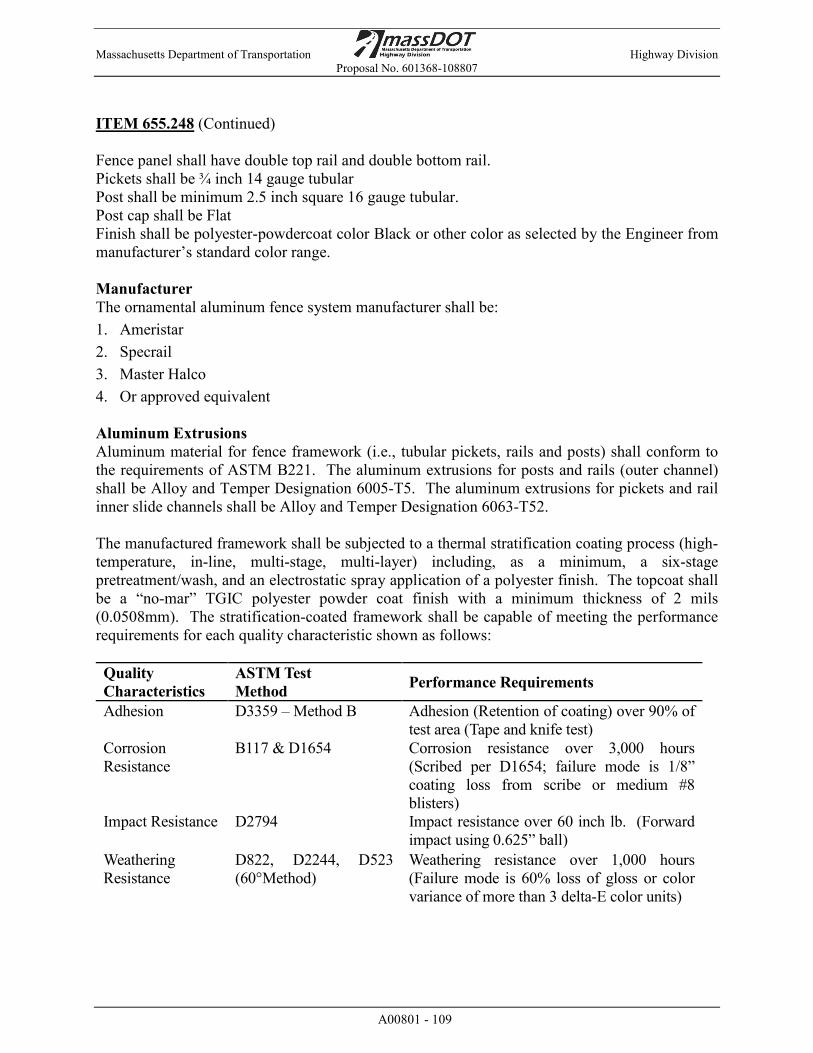
Massachusetts Department of Transportation Highway Division Proposal No. 601368-108807
A00801 - 109
ITEM 655.248 (Continued) Fence panel shall have double top rail and double bottom rail. Pickets shall be ¾ inch 14 gauge tubular Post shall be minimum 2.5 inch square 16 gauge tubular. Post cap shall be Flat Finish shall be polyester-powdercoat color Black or other color as selected by the Engineer from manufacturer’s standard color range. Manufacturer The ornamental aluminum fence system manufacturer shall be: 1. Ameristar 2. Specrail 3. Master Halco 4. Or approved equivalent Aluminum Extrusions Aluminum material for fence framework (i.e., tubular pickets, rails and posts) shall conform to the requirements of ASTM B221. The aluminum extrusions for posts and rails (outer channel) shall be Alloy and Temper Designation 6005-T5. The aluminum extrusions for pickets and rail inner slide channels shall be Alloy and Temper Designation 6063-T52. The manufactured framework shall be subjected to a thermal stratification coating process (high-temperature, in-line, multi-stage, multi-layer) including, as a minimum, a six-stage pretreatment/wash, and an electrostatic spray application of a polyester finish. The topcoat shall be a “no-mar” TGIC polyester powder coat finish with a minimum thickness of 2 mils (0.0508mm). The stratification-coated framework shall be capable of meeting the performance requirements for each quality characteristic shown as follows: Quality Characteristics
ASTM Test Method Performance Requirements
Adhesion D3359 – Method B Adhesion (Retention of coating) over 90% of test area (Tape and knife test)
Corrosion Resistance
B117 & D1654 Corrosion resistance over 3,000 hours (Scribed per D1654; failure mode is 1/8” coating loss from scribe or medium #8 blisters)
Impact Resistance D2794 Impact resistance over 60 inch lb. (Forward impact using 0.625” ball)
Weathering Resistance
D822, D2244, D523 (60°Method)
Weathering resistance over 1,000 hours (Failure mode is 60% loss of gloss or color variance of more than 3 delta-E color units)
Massachusetts Department of Transportation Highway Division Proposal No. 601368-108807
A00801 - 110
ITEM 655.248 (Continued) Material for fence pickets shall be 1" square x 0.062" thick extruded tubing. The cross-sectional shape of the rails shall have an outside cross-section dimension of 1.75" square. The top wall of the outer channel of the rail shall be 0.100" thick; the sidewalls shall be 0.120" thick for superior vertical load strength. The inner slide channel of the rail shall be 0.070" thick. Picket holes in the rail shall be spaced 4.715 inches on center. Picket retaining rods shall be 0.125" diameter galvanized steel. High quality PVC grommets shall be supplied to seal all picket-to-rail intersections. Fence Posts Posts shall be a minimum of 2-1/2" square with a perimeter wall thickness of 0.080" and an interior reinforcing web thickness of 0.080". Fasteners All fasteners shall be stainless steel with zinc dichromate coating for enhanced corrosion resistance. Bracket to rail attachments shall be made using specially designed one-way tamperproof security bolts with inverted “t-nuts”. Bracket to post connections shall be made using self-drilling hex-head screws. Accessories All castings used for post caps, rings, and miscellaneous adornments shall be aluminum. Only stainless steel fasteners may be used with these accessories. Footings Materials for footings shall meet the requirements specified in the following Subsection of Division III, Materials: Cement Concrete M4.02.00 Fabrication Pickets, rails, and posts shall be pre-cut to specified lengths. Rails shall be pre-punched to accept pickets. The rail inner slide shall be fully inserted into the rail outer channel to form the raceway for the internal retaining rod. Grommets shall be inserted into the pre-punched holes in the rails, and pickets shall be inserted through the grommets so that pre-drilled picket holes align with the internal raceway of the two-part rails. (Note: This can best be accomplished by using an alignment template). Retaining rods shall be inserted into each rail so that they pass through the pre-drilled holes in each picket, thus completing the panel assembly. Completed panels shall be capable of supporting a 300 lb. load (applied at midspan) without permanent deformation. Panels shall be biasable to a 25% change in grade.

Massachusetts Department of Transportation Highway Division Proposal No. 601368-108807
A00801 - 111
ITEM 655.248 (Continued) Installation Preparation All new installation shall be laid out by the contractor in accordance with the approved shop drawings and the construction plans. Tops of concrete footings shall be held a minimum of 4 inches below finished grade. Fence Installation Fence posts shall be spaced as indicated on the Drawings, and at custom lengths as required for end panels, plus or minus 1/2", and set in accordance with the Drawings and the manufacturer’s recommendations. Panels shall be attached to posts using mechanically fastened panel brackets supplied by the manufacturer. All posts shall be set plumb. In setting the posts, precautions shall be taken to ensure proper offset, alignment, and leveling to prevent bending or twisting of the rail. When cutting/drilling rails or posts in the field, the contractor shall adhere to the following steps to seal the exposed surfaces: 1) Remove all metal shavings from cut area. 2) Apply custom finish paint matching fence color. Paint spray cans or paint pens shall be obtained from the fence manufacturer, of the same paint used to prime and finish exposed surfaces; it is recommended that paint pens be used to prevent overspray. Warranty The entire fence system shall have a limited lifetime warranty against defects in workmanship and material while the finish must also carry a limited lifetime warranty against cracking, chipping or peeling. Method of Measurement Item 655.248 will be measured for payment per Foot from outside to outside of end posts, complete in place. No separate measurement will be made for end posts. Basis of Payment Item 655.248 will be paid for at the Contract unit price per Foot, which price shall include all excavation, drilling, concrete footing, and concrete fill and epoxy grout, hardware, bolts, bearing plates, angle plates, brackets, labor, materials, equipment, and all incidental costs required to complete the work.
Massachusetts Department of Transportation Highway Division Proposal No. 601368-108807
A00801 - 112
ITEM 655.3 HANDRAIL AT STAIRS FOOT The work under this item shall conform to the relevant provisions of Section 660 of the Standard Specifications and the following: Work under this item shall consist of providing shop drawings, furnishing and installing handrails as shown on the drawings or as required by the Engineer: Metal handrail for stairs. References Work shall be accomplished in accordance with regulations of local, county, state and federal agencies or utility company standards as they apply. ASTM: American Society for Testing and Materials A36/ A36M-00 Carbon Structural Steel A48-94 Gray Iron Castings A53/ A53M-99b Pipe, Steel, Black and Hot-dipped, Zinc-coated A108-99 Steel Bars, Carbon cold Finished, Standard Quantity A123/ A123M-97a Zinc (Hot-dip galvanized) Coatings on Iron and Steel Products A153/ A153M-98 Zinc Coating (Hot-dip) on Iron and Steel Hardware A193/ A193M-99a Alloy-Steel and Stainless-Steel Bolting Materials for High
Temperature Service A276-98b Stainless Steel Bars and Shapes. A307-97 Carbon Steel Bolts and Studs, 60000 PSI Tensile Strength A312/ A312M-00 Seamless and Welded Austenitic Stainless-Steel Pipes A385-00 Standard Practice for Providing High-Quality Zinc Coatings (Hot-Dip) A500-99 Cold-formed Welded and Seamless Carbon Steel Structural Tubing in
Rounds & Shapes A501-89 Hot-formed Welded and Seamless Carbon Steel Structural Tubing A510-96 Wire rods and coarse Round Wire, Carbon Steel A572-92 High Strength Low Alloy Columbium-Vanadium Steel AISI: American Iron and Steel Institute AISI 304 Stainless Steel Alloy Designation AISI 316 Stainless Steel Alloy Designation AISI M1020 Merchant Quality Steel AWS: American Welding Society D1.1-2000 Structural Welding Code – Steel D1.6-99 Structural Welding Code – Stainless Steel

Massachusetts Department of Transportation Highway Division Proposal No. 601368-108807
A00801 - 113
ITEM 655.3 (Continued) Delivery, Storage and Handling All stored materials and items shall be protected from weather, careless handling, and vandalism. Items which become rusted or damaged because of non-compliance with these conditions will be rejected and shall be replaced without additional cost. Protection of Coated Metal Items: All fully coated and cured assemblies shall be protected from handling and shipping damage with the prudent use of padded slings, dunnage, separators and tie downs. Loading procedures and sequences shall be designed to protect all coated surfaces. Erection marks for field identification of members and weight marks shall be affixed in such a manner as to facilitate removal upon final assembly without damage to the coating system. Certificates Provide certificates listing materials used in coating systems and certify compliance with standards designated. Certificate of Compliance from Galvanizer: Submit notarized Certificate of Compliance with application for payment for galvanizing, signed by galvanizer, indicating compliance with requirements of specifications. Include scope of services provided, and quantity and itemized description of items processed. The notarized statement shall declare the day each piece was galvanized. The stamp shall indicate the ASTM Standard and the coating weight. The Contractor shall submit in writing the names and addresses where all galvanizing, surface preparation, priming, intermediate coat application and finish coat application are to be performed. Visual Stamp: The galvanizer shall mark all lots of material with a clearly visible stamp or tag indicating the name of the galvanizer, the weight of the nickel-zinc coating, and the applicable ASTM Specification Numbers. Materials Provide only new materials, free from defects impairing strength, durability or appearance and of the quality specified. Metals Structural steel
1. Tubular shapes shall conform to ASTM A 500, grade B 2. Bars, plates and angles shall conform to ASTM A36 3. Pipes shall conform to ASTM A501 or ASTM A53, Types E or S, grade B 4. Steel bolts, washers, and nuts shall conform to ASTM 307. 5. Filler metal for welding: Welding electrodes for manual shielded metal arc welding
shall conform to ASTM A233, E60 or E70 Series. Bare electrodes and granular flux used in the submerged-arc process shall conform to AISI Specifications.

Massachusetts Department of Transportation Highway Division Proposal No. 601368-108807
A00801 - 114
ITEM 655.3 (Continued) Galvanizing All steel components of the metal railing including hardware, attachments or other specified steel elements shall be galvanized. Do not galvanize stainless steel components. Field priming of hot dip galvanizing will not be permitted. Galvanizing shall comply with ASTM A123M-97A, A153/A153M-98, ASTM A385-00 as applicable. Unless otherwise indicated, all items to be galvanized under this Section shall receive a 3 mil coating of zinc. Touch-Up and Repair: For damaged and field welded zinc-coated surfaces, clean welds, bolted connections and abraded areas. Following galvanizing, each item shall receive surface grinding to remove lumps, sags or spikes resultant from the galvanizing process. The finished surface following grinding shall be hand smooth and without irregularities. Take care not to damage the galvanized surface coating. Shop Applied Coatings All steel components of the metal railing including hardware, attachments or other specified steel elements shall be shop painted. Do not shop paint stainless steel components. Touch-up paint for field touch-up of galvanized surfaces: Touch up paint shall be a two-component, moisture-cured, zinc-rich inorganic or organic primer. Recommended Dry Film Thickness shall be as recommended by manufacturer and approved by City. Acceptable products and their manufacturers shall include the following: 1. Ply-Tile Epoxy Organic Zinc Rich Primer Manufactured by M.A.B Industrial Coatings Broomall, PA 19008 2. Dimetcote 9 Ameron International Alpharetta, GA 30004 3. Metalhide 97-673 Series, 1001 Inorganic Zinc Rich Coating PPG Architectural Finishes, Inc. One PPG Place Pittsburgh, PA 15272 4. Zinc Clad III HS, Organic Zinc-Rich Epoxy Primer Sherwin-Williams Company www.sherwin-williams.com 5. An approved equal

Massachusetts Department of Transportation Highway Division Proposal No. 601368-108807
A00801 - 115
ITEM 655.3 (Continued)
Factory Applied Primer Over Hot-Dip Galvanizing Primer coating for shop painting of galvanized surfaces shall be factory-applied polyamide epoxy primer, 3.0 mils dry film thickness minimum. Acceptable products may be an approved equal or from one of the following: 1. Ply-Tile 520-W-45 Epoxy Primer Manufactured by M.A.B Industrial Coatings Broomall, PA 19008 2. Amercoat 385 Ameron International Alpharetta, GA 30004 3. Pitt-Guard 97-946 Series All Weather Direct-to-Rust Epoxy Coatings PPG Architectural Finishes, Inc. One PPG Place Pittsburgh, PA 15272 4. Macropoxy 646 Fast Cure Epoxy Sherwin-Williams Company www.sherwin-williams.com Factory Applied Architectural Finish Over Hot-Dip Galvanizing and Primer Provide factory-applied High-Build Aliphatic Acrylic Polyurethane color coating compatible with primer over primed galvanized steel as previously referenced. Apply coating at the galvanizer’s plant, in a controlled environment meeting applicable environmental regulations. Surface Preparation: Coat over preceding epoxy or urethane coat within 24 hours Finish Coat color shall be Gloss Black, or other color as selected by the Engineer and the City Representative. All hardware shall be painted in corresponding color as adjacent members as noted on the Drawings. Anchoring Systems Grout as required for anchoring shall be a pourable, quick setting, non-metallic and non-shrinking hydraulic cement grout. Ferrules for use in anchoring moveable metal railing posts shall be galvanized steel ferrules suitable for use in cast-in-place concrete conditions where ferrule is fully integrated with concrete steel reinforcement. Ferrules shall provide 240 MPa yield strength per bolt. Ferrules shall be 3/4 inch inside diameter size with threaded embedment no less than 3 inch depth below concrete surface. Provide 3/4 inch stainless steel, allan-headed threaded plugs to be screwed into the open ferrules when temporary posts of metal rail
Massachusetts Department of Transportation Highway Division Proposal No. 601368-108807
A00801 - 116
ITEM 655.3 (Continued) Metal Fabrication Arc welding procedures shall conform to the current standards of the AWS. All welds shall be as designated on the plans and shall be ground smooth and flush to a neat finish. All welds shall be watertight. Care shall be taken to minimize distortion due to heat. Metal shall not be primed or painted before welding. Welding shall be continuous except where tack welding or stitch welding are specifically permitted. Tack or stitch welding will not be permitted on exposed surfaces. All exposed welds shall be ground smooth. Do all shop drilling, tapping, shop fitting, shop cutting, shop welding, and bolting required to erect, install and fit metal work to adjoining work. Furnish all screws, bolts, anchors, etc., required to attach metal work securely to adjoining work. Install all supports and anchors for metal work except those to be cast into concrete as indicated. Finish Schedule Color Item Galvanized Two-Coat Paint System Pure Black Posts and Railings Yes Yes Application of Paint and Finishes to Metal Surfaces All metal shall be primed and painted as described in this Section. All coatings shall be applied in the shop except for field touch-up after installation. See requirements for field touch-up as described in this Section. All surface preparation and coating work, including field touch up work, shall be as specified under the work of this Section. All galvanized steel surfaces shall receive the 2-coat shop applied paint system as specified in this Section except the following locations that shall be masked off and treated as follows. Faying surfaces of slip-critical bolted connections shall receive only a single application of primer. The dry film thickness shall be no greater than the thickness tested on the coating manufacturer's Certified Test Report for slip coefficient. Miscellaneous metal surfaces within 4 inches of field welds shall receive only a single coating of primer at 0.5 - 1.5 mils dry film thickness. Galvanized steel surfaces to be in contact with concrete shall not be coated. For galvanized items to be set in cast or cored concrete walls, footings or foundations, ensure that 2 coat paint coatings extend below the horizontal surface of the concrete by no less than one inch or as shown on the Contract Documents.
Massachusetts Department of Transportation Highway Division Proposal No. 601368-108807
A00801 - 117
ITEM 655.3 (Continued) Edges and shop welds of galvanized steel items shall be locally hand-striped with a brush in the longitudinal direction with an additional coat of the epoxy or urethane coating prior to application of the finish aliphatic urethane coating. The coating manufacturer shall be consulted to determine the appropriate epoxy or urethane coating to use for striping. The application of the striping materials shall be in accordance with the coatings manufacturer’s written instructions. The striping material shall be tinted to distinguish it from the intermediate coats. Application Methods The coating system shall be applied by spray equipment of a type and size capable of applying each coat within the required thickness range. The applicator shall strictly adhere to the manufacturer's recommendations about application methods, cure times, temperature and humidity restrictions and recoat times for each individual coat of the specified system. Brushes shall be used in areas where spray application will not achieve acceptable results. Brushing technique shall be performed in a manner that will provide a uniform, blended finish. No coating material shall be thinned in any way except as directed by manufacturer. Conventional spray equipment with mechanical agitators shall be used for prime coat application on bare steel and for epoxy or urethane intermediate coat on galvanized surfaces. All storage, mixing, thinning, application and curing efforts, techniques and methods shall be accomplished in strict accordance with the printed material data sheets and application instructions published by the respective coating material manufacturer. Surfaces shall be painted with the specified prime coat material before the end of the same work shift that they were blast cleaned and before any visible rust back occurs. Applied coatings shall not have runs, sags, pinholes or discontinuities. The dry film thickness shall be within the range specified in the manufacturer's printed literature for the specified coating system. Dry film thickness shall be measured in accordance with SSPC-PA 2. The intermediate coat shall be of a contrasting color to the prime and top coat colors. There shall be no color variation in the topcoat as determined by comparison with Federal Standard 595B. All storage, mixing, thinning, application and curing efforts, techniques and methods shall be accomplished in strict accordance with the written requirements and procedures published by the respective coating material manufacturer. Additional coats: Provide additional coats necessary to eliminate show through and bleed through conditions.
Massachusetts Department of Transportation Highway Division Proposal No. 601368-108807
A00801 - 118
ITEM 655.3 (Continued) Drying Time: Allow manufacturer’s recommended drying time between successive coats. And allow each coat to thoroughly dry prior to application of subsequent coat. All compressed air sources shall be properly sized and designed with oil and moisture separators, attached and functional, to allow air at the nozzle, either for blast cleaning, blow-off, painting or breathing, to be oil-free and moisture-free. It shall be of sufficient pressure to accomplish the associated work efficiently and effectively. Surfaces not in contact with other steel surfaces but inaccessible after assembly shall be coated prior to assembly. Critical attention shall be given to edges and bolted connections. All bolts, nuts and washers shall be fully coated, with no gaps left unfilled and un-coated. Stainless steel hardware shall not be painted. Adhesion strength of the fully coated assemblies shall be within 80 percent of the values for Adhesion as described in the approved manufacturer’s literature measured per ASTM D4541 using apparatus under Annex A4. Strict attention must be directed to the re-coat times of all applied materials. Shop bolted connections shall also have all bolt heads and nuts striped in a circular brush motion with the same material. All applied coating shall have no runs, sags, or discontinuities; the dry film thickness shall be within the range specified. There shall be no color variation in the topcoat as determined by Federal Standard 595B. Also, there shall be no gloss variation in the topcoat where tested in accordance with ASTM D523. Method of Measurement Item 655.3 will be measured per Foot of handrail installed, complete in place. Basis of Payment Item 655.3 will be paid for at the contract unit bid price per Foot, which price shall include all drilling, epoxy or grout, labor, material, tools and equipment, and all incidental costs required to complete the work. The concrete stairs will be paid for under Item 901.
Massachusetts Department of Transportation Highway Division Proposal No. 601368-108807
A00801 - 119
ITEM 690. STONE MASONRY WALL REMOVED AND CUBIC YARD
REBUILT IN CEMENT MORTAR The work under this item shall conform to the relevant provisions of Section 690 of the Specifications and the following: The work shall consist of restoring damaged or unsound areas of concrete and/or stone for the existing retaining wall as shown on plans or as directed by the Engineer. This item shall also be used to modify the proposed walls, as required, to avoid existing utilities. The work includes removing undesirable vegetation, cleaning of the surface, all excavation and backfill; all necessary demolition; all concrete and masonry work; resetting loose stones, protecting existing utilities as required, and any miscellaneous work necessary to repair the damaged sections of wall. Prior to beginning work on this item, the Engineer will inspect the existing retaining walls and identify locations that require repairs. The exact extent of the areas to be repaired and the type of repair will be determined by the Engineer in the field as the work progresses. At the proposed walls, there are three locations where there is a potential for conflicts with existing utilities. The Contractor shall coordinate with the utility owners to see if the utilities need to be relocated or to determine the best method for constructing the wall around the existing utility. The section of wall that needs to be constructed around the existing utility shall be paid for under this item. Method of Measurement Item 690. will be measured per Cubic Yard of wall rebuilt, complete in place. Basis of Payment Item 690. will be paid for at the Contract unit price per Cubic Yard, which price shall include all labor, materials, equipment, and incidentals required to complete the work. The removal of undesirable vegetation shall be paid for under Item 102.02.
Massachusetts Department of Transportation Highway Division Proposal No. 601368-108807
A00801 - 120
ITEM 694. RESTORE AND RESET HISTORICAL MARKER EACH The work under this item consists of removing, cleaning, repairing, painting, and resetting the existing “Jonas Rice” Massachusetts Bay Colony Tercentenary Commission historical marker in Worcester located along Grafton Street at Sta 60+75 Left ±. The marker consists of an original cast iron tablet, which was fabricated circa 1930, and a replacement steel pipe post. Note: The cast iron tablet is a one-of-a-kind historic object that must be treated with care as it is removed, transported, stored, repaired, cleaned, painted, and reset. Inspection and photography Prior to performing the work, the Contractor and Engineer shall jointly inspect the Marker at its current location and shall determine if any repairs to the cast iron tablet might be necessary. The Contractor shall provide color digital photographs of the Marker to the Engineer showing the Marker in its existing condition and location prior to beginning any work under this item. Qualified Conservation Firms The Contractor shall engage the services of one of the following three qualified firms to complete the cleaning and repainting of the cast iron Tablet. Each of these firms has proven experience in the conservation of outdoor metal sculpture or plaques. Daedalus, Inc. Schiff Architectural Details Skylight Studios, Inc. Contact: Josh Craine Contact: Jeff Schiff Contact: Robert Shure 205-3 Arlington Street 120 Eastern Avenue 105 Salem Street Watertown, MA 02472 Chelsea, MA 02150 Woburn, MA 01801 617-926-7590 617-887-0202 781-933-3822 www.daedalusart.com www.schiffarchitecturaldetail.com [email protected] Restoration Removal, Transportation, and Storage: The cast iron tablet shall be carefully removed from the steel pipe post and shall be carefully packed and protected during transportation and storage to prevent damage. The existing steel pipe post may be discarded. Cleaning: All surfaces of the cast iron tablet shall be blast cleaned to Society for Protective Coatings (SSPC) SP 10 requirements. The abrasive used for blasting shall consist of a fine sand, baking soda, or similar material. Alternate methods of surface preparation may be submitted for approval by the Engineer. Special attention shall be given to the cleaning process to ensure that the raised elements of the tablet are not eroded or rounded-over by the abrasive cleaning process. The least abrasive media and air pressure shall be used for the blast cleaning in order to prevent defacing the tablet.

Massachusetts Department of Transportation Highway Division Proposal No. 601368-108807
A00801 - 121
ITEM 694. (Continued) Lead: The existing coating shall be tested for lead content. If found to be lead-based, the paint removed during the cleaning process, as well as the blast media, shall be considered lead waste, and shall be disposed of in accordance with applicable regulations. Proof of proper disposal of the lead waste shall be submitted to the Engineer. Repairs: Any structural or aesthetic damage on the tablet that may have been identified by the Contractor or the Engineer shall be repaired as part of this work. Appropriate repair procedures shall be approved by the Engineer. Painting: All surfaces of the cast iron tablet shall be recoated with a two-coat paint system consisting of epoxy primer and urethane top coat selected from the MassDOT Qualified Products List. The background panel on both sides of the Tablet shall be painted silver (FST 16515). The letters, dates, and trim on the Tablet shall be painted black (FST 17038) on their faces only; the collar at the bottom of the Tablet also shall be painted black. The Coat of Arms of the Commonwealth on both sides of the Tablet shall be painted blue (FST 15187) and gold (FST 17043). Details of the Coat of Arms shall be painted in the following manner: the shield and ribbon in blue; the lettering on the ribbon, the Native American figure and bow, the five-pointed star, and the arm with sword in gold; the rope under the arm in gold and blue, with the six sections of the rope alternating in gold and blue, beginning on the left with gold. All paints shall be fabricated by the same manufacturer and shall be compatible with each other. All colors and paint selection shall be approved by the Engineer. Resetting: The cast iron tablet shall be reset on a new steel pipe post at the back of the new sidewalk at the same location along Grafton Street at Sta 60+75 Left ±. The bottom of the tablet shall be installed exactly 84" above the ground, according to the original specifications from 1930. The tablet shall be placed on the post perpendicular to the sidewalk. Any replacement hardware shall be painted to match the Tablet as described above. Any miscellaneous hardware required for resetting shall be considered incidental and included in this item. Method of Measurement Item 694. will be measured per Each historical marker removed, cleaned, repaired, painted, and reset. Basis of Payment Item 694. will be paid for at the contract unit price per Each, which shall include all labor, equipment, materials, and incidental costs required to complete the work.

Massachusetts Department of Transportation Highway Division Proposal No. 601368-108807
A00801 - 122
ITEM 697.1 SILT SACK EACH Work under this item shall conform to the relevant provisions of Sections 227 and 670 of the Standard Specifications and the following: The work under this item includes the furnishing, installation, maintenance and removal of a reusable fabric sack to be installed in drainage structures for the protection of wetlands and other resource areas and the prevention of silt and sediment from the construction site from entering the storm water collection system. Devices shall be ACF Environmental (800)-448-3636; Reed & Graham, Inc. Geosynthetics (888)-381-0800; The BMP Store (800)-644-9223; or approved equal. Silt sacks shall be installed in retained existing and proposed catch basins and drop inlets within the project limits and as required by the Resident Engineer. The silt sack shall be as manufactured to fit the opening of the drainage structure under regular flow conditions and shall be mounted under the grate. The insert shall be secured from the surface such that the grate can be removed without the insert discharging into the structure. The filter material shall be installed and maintained in accordance with the manufacturer’s written literature and as directed by the Engineer. Silt sacks shall remain in place until the placement of the pavement overlay or top course and the graded areas have become permanently stabilized by vegetative growth. All materials used for the filter fabric will become the property of the Contractor and shall be removed from the site. The Contractor shall inspect the condition of silt sacks after each rainstorm and during major rain events. Silt sacks shall be cleaned periodically to remove and disposed of accumulated debris as required. Silt sacks, which become damaged during construction operations, shall be repaired or replaced immediately at no additional cost to the Department. When emptying the silt sack, the contractor shall take all due care to prevent sediment from entering the structure. Any silt or other debris found in the drainage system at the end of construction shall be removed at the Contractors expense. The silt and sediment from the silt sack shall be legally disposed of offsite. Under no condition shall silt and sediment from the insert be deposited on site and used in construction. All curb openings shall be blocked to prevent stormwater from bypassing the device. All debris accumulated in silt sacks shall be handled and disposed of as specified in Section 227 of the Standard Specifications Compensation Silt sacks will be measured and paid at the Contract unit price per each, complete in place, which price shall include all labor, materials, equipment and incidental costs required to complete the work. No separate payment will be made for removal and disposal of the sediment from the insert, but all costs in connection therewith shall be included in the Contract unit price bid.
Massachusetts Department of Transportation Highway Division Proposal No. 601368-108807
A00801 - 123
ITEM 698.1 GEOTEXTILE FABRIC FOR STABILIZATION SQUARE YARD The work under this item shall consist of supplying and placing a geotextile fabric in the construction of the 2:1 slopes along Grafton Street as shown on the plans. The fabric shall conform to requirements of AASHTO M 288 for stabilization. Installation shall be in conformance with the Manufacturer’s specifications. Method of Measurement Item 698.1 will be measured per Square Yard of geotextile fabric in place and accepted by the Engineer. Basis of Payment Item 698.1 will be paid for at the contract unit price per Square Yard. This price shall include all labor, materials, equipment, and incidentals required to complete the work. No separate payment will be made for sewing and for overlapping material, but all costs required to complete the work. ITEM 701.3 STAMPED CEMENT CONCRETE ACCENT STRIP SQUARE YARD ITEM 701.4 STAMPED CEMENT CONCRETE PAVEMENT SQUARE YARD
TYPE 2 – VEHICULAR ITEM 701.5 STAMPED CEMENT CONCRETE PAVEMENT SQUARE YARD
TYPE 3 - PEDESTRIAN The work under these items shall conform to the relevant provisions of Sections 701 of the Standard Specifications and the following: Stamped cement concrete pavements and accent strips shall consist of integrally colored (i.e., incorporated through-out the mix) and dry-shake colored stamped cement concrete complete in place as shown on the plans. Prior to ordering materials, the Contractor shall submit pattern samples and color samples of each cement concrete type to the Engineer and the City of Worcester for approval. Samples of other materials to be used and samples for testing shall be submitted as requested by the Engineer. A 4 foot by 4 foot (4’ x 4’) cured “mock up” of each type of colored concrete pavement shall be constructed for review and approval by the Engineer and the City of Worcester.

Massachusetts Department of Transportation Highway Division Proposal No. 601368-108807
A00801 - 124
ITEMS 701.3, 701.4, and 701.5 (Continued) Materials Concrete mix design shall meet the requirements of Section 701 of the Standard Specifications. Do not add calcium chloride to mix as it causes mottling and surface discoloration. Supplemental admixtures shall not be used unless approved by manufacturer of color admixture. Add air-entraining agent to concrete work in amounts of 4-7 percent of total concrete volume, or as otherwise recommended by testing lab. Add coloring admixture in quantities recommended by admixture manufacturer to achieve selected color. Add colored admixture to the mix according to manufacturer’s written instructions in premeasured bags, not by weight of cement content. Coloring agents for the colored and stamped concrete shall all be supplied by the same manufacturer as part of an integrated system. Color Admixtures for integrally colored concrete shall be a colored, water-reducing, admixture containing no calcium chloride with coloring agents that are lime proof and UV resistant. Colored admixture shall conform to the requirements of ACI 303.1, ASTM C979, ASTM C494, and AASHTO M194. Color Hardeners shall be a heavy-duty grade, UV-stable, dry-shake material for intensely coloring and hardening concrete flatwork. Color hardener shall be a blend of mineral oxide pigments, cement, graded silica aggregates and aluminum oxide, with conditioning agents to improve workability. Release Agent shall be a dry blend of chemical powders and color pigments designed as part of the coloring and patterning system to provide the clean release of the texturing tools form the concrete surface. Curing Compounds for Colored Concrete: Curing and sealing compound shall be a ready to use water-based membrane curing compound and sealer designed to increase impact strength of the colored concrete and to repel stains. Curing compound shall comply with ASTM C309, and the slip-resistance requirements of ASTM D-2047, be suitable for exterior use and of same manufacturer as colored admixture, for use with integrally colored concrete.
Massachusetts Department of Transportation Highway Division Proposal No. 601368-108807
A00801 - 125
ITEMS 701.3, 701.4, and 701.5 (Continued) Concrete Coloring System Colors Color Admixture and Color Hardener for ‘Stamped Concrete Accent Strip’ and for ‘Stamped Reinforced Concrete Pavement Type 2 – Brick Pattern’ shall be a Brick Red, Deep Red, or other dark red color or other medium to dark color as selected by the Engineer and City of Worcester from the manufacturer’s standard color range. Color Admixture and Color Hardener for ‘Stamped Concrete Pavement Type 3 – Cobble Pattern’ shall be a Deep Gray color or other medium to dark color as selected by the Engineer in consultation with the City of Worcester, from the manufacturer’s standard color range. Powder Antiquing Release Agent for each type of stamped concrete: Colors shall be as selected by Engineer from approved manufacturer's standard colors. Joint Sealant colors shall match the colored concrete surface. Stamp/Imprinting Patterns Stamp pattern for Item 701.3 and Item 701.4 shall be a Used Brick pattern as indicated on the Drawings, or other brick-like pattern as selected by Engineer in consultation with the City of Worcester from the approved manufacturer’s standard brick patterns. Pattern templates shall be provided for linear accent strip treatment for borders of the stamped concrete, and for running bond pattern for the field of the large paved areas, all as indicated on the detail plans on the drawings. Stamp pattern for Item 701.5 shall be a raised river stone surface pattern, with typical raised rounded stone size of approximately 3”-4” by 5”-6”, providing stone surface raised up to 1-2 inches above the surface plane. Reinforcing shall be as indicated on the Drawings and in accordance with the Standard Specifications. Installation Subgrade preparation and formwork shall be installed to the lines, grades, and depths indicated on the Drawings and in accordance with Section 701. Place integrally colored concrete mix according to the Standard Specifications and the requirements of American Concrete Institute (ACI) 301, 302, and 304. Minimize handling to prevent segregation. Do not add water to the mix in the field. After consolidating and screeding, float concrete to the gradients indicated.

Massachusetts Department of Transportation Highway Division Proposal No. 601368-108807
A00801 - 126
ITEMS 701.3, 701.4, and 701.5 (Continued) Apply dry-shake color hardener prior to the application of the imprinting pattern. Apply at rate recommended by manufacturer, in two or more shakes, in accordance with manufacturer’s instructions. Float after each shake, and trowel only after the final color hardener shake. While concrete is still in a plastic state, apply release agent to the troweled surface, and then the surface shall be uniformly stamped/imprinted, applying the pattern as indicated on the drawings and in accordance with the tool manufacturer's instructions. Provide a uniform pattern and uniform depth of stamping. Touch-up pattern and finish edges with hand tools as necessary. Immediately after finishing concrete, apply curing and sealing compound for integrally colored concrete according to manufacturer's instructions using manufacturer's recommended application techniques. Apply curing and sealing compound at consistent time for each pour to maintain close color consistency. Curing compound shall be same color as the colored concrete and supplied by same manufacturer of the colored admixture. Precautions shall be taken in hot weather to prevent plastic cracking resulting from excessively rapid drying at surface as described in CIP 5 Plastic Shrinkage Cracking published by the National Ready Mixed Concrete Association. Do not cover concrete with plastic sheeting. Minor variations in appearance of colored concrete, which are like natural variations in color and appearance of uncolored concrete, are acceptable. Method of Measurement Items 701.3, 701.4, and 701.5 will be measured per Square Yard of concrete placed and accepted by the Engineer. Basis of Payment Items 701.3, 701.4, and 701.5 will be paid for at the respective contract unit price per Square Yard. This price shall include all labor, materials, equipment, and incidental costs required to complete the work. The “mock up”, joint sealer or backer rods, will be incidental to the relevant item.

Massachusetts Department of Transportation Highway Division Proposal No. 601368-108807
A00801 - 127
ITEM 703. HOT MIX ASPHALT DRIVEWAY TON The work under this item shall conform to the relevant provisions of Section 701 and Section 450 and to the following: HMA driveway surface course shall be a compacted thickness of 1 1/2 inches Superpave Surface Course - 9.5 (SSC-9.5). The intermediate course shall be a compacted thickness of 2 inches Superpave Intermediate Course - 12.5 (SIC–12.5). All Superpave HMA mixtures under this item shall be either 50 or 65 gyration mixtures This item shall not be subject to the Quality Assurance requirements of Section 450 Hot Mix Asphalt Pavement. Existing pavements shall be sawcut in accordance with the requirements of Subsection 450.49 as shown on the plans and as required by the Engineer. Method of Measurement and Basis of Payment Item 703.will be measured and paid as per Subsections 701.80 and 701.81 including all sawcutting. All costs including the WMA additive, equipment, labor, Manufacturer’s representative, production of samples and incidental costs required to modify the HMA shall be incidental to this item with no additional compensation.

Massachusetts Department of Transportation Highway Division Proposal No. 601368-108807
A00801 - 128
ITEM 706.9 TEXTURIZED SYNTHETIC PAVEMENT SQUARE YARD The work under this item shall consist of preparing pavement surface and placement of six foot wide Texturized Synthetic Pavement at all proposed crosswalk locations in accordance with the following: Preparation of Asphalt Surface The section of pavement to be replaced shall be sawcut in neat lines six feet apart in the direction of the proposed crosswalk. The final surface pavement shall then be milled to an approximate depth of 0.75 inches. The Contractor shall immediately remove all residual material resulting from this work. All excavated material shall be disposed of by the Contractor offsite. Installation of Texturized Synthetic Pavement The Contractor shall be responsible for the preparation, placement and patterning of Texturized Synthetic Pavement. This synthetic paving material shall be composed of a hot-applied, resin-based compound formulated with a color stable pigment throughout that can be surface textured to simulate a brick pattern. Said pattern shall be oriented such that the continuous lines of the brick pattern shall be perpendicular to the parallel edges of the proposed crosswalk. The Contractor will be required to overlay in previously prepared recessed pavement surfaces as described above, and as required and approved by the Engineer. The Contractor must be a manufacturer authorized applicator, experienced with this specialized system, satisfactory to the Engineer. Contractor shall furnish shop drawings, from manufacturer, to confirm design intent. A manufacturer representative shall be present at all times during the placement and curing of the textured synthetic pavement materials. Using manufacturer prescribed methods and equipment, the Contractor shall adequately heat and uniformly mix the synthetic material(s) together. The contractor shall provide samples of all applicable colors, from the available pigments supplied by the manufacturer, to the Engineer/City of Worcester for approval prior to installation. The color shall be a brick red and shall match the approved color of the Stamped Cement Concrete Accent Strip. Maximum heating temperature of the completed formulation is 440 degrees Fahrenheit. The Contractor shall then apply the heated, mixed synthetic material to the surface of the hardened, structurally sound, asphalt pavement. The synthetic material shall be spread and leveled to the desired build thickness of 0.75 inches, using manufacturer’s specialized ironing tools, heated sufficiently to smooth the surface to a state of readiness for texturing. No material shall be applied when precipitation is present. No underlayment of any type shall be placed between the prepared surface to receive the overlay and Texturized Synthetic Pavement Material. The Texturized Synthetic Pavement shall be applied directly to the prepared surface to ensure a good bond. Texturing will begin immediately after leveling has occurred, while the material is still hot enough to allow the mold selected, to adequately penetrate the surface and create the desired pattern or form.
Massachusetts Department of Transportation Highway Division Proposal No. 601368-108807
A00801 - 129
ITEM 706.9 (Continued) Once the finished surface has cooled completely and has hardened to the manufacturer’s specification to support vehicular and pedestrian traffic, the application area may be opened to vehicular and/or pedestrian traffic. Any residual material resulting from this work shall be removed and disposed of in a proper manner offsite. The completed work area shall be left in a neat and clean condition, satisfactory to the Engineer. The products used in this surfacing system shall meet the material specifications outlined below and conform to the minimum following physical and performance properties: hot-applied resin-based compound developed specifically for use on asphalt or cement concrete, with superior adhesion, flexibility and abrasion resistance characteristics, as well as color stability, chemical resistance and scrub ability. The Contractor, during the operation of work, to save from harm and injury, any structure, public or private, situated above or below the surface and lying within the scope of the project. If during the execution of the work, the Contractor, through willfulness or carelessness, permits or causes any damage, the cost of satisfactory repair or replacement shall be the financial responsibility of the Contractor. Synthetic Pavement Material The material to be utilized in the Texturized Synthetic Pavement shall conform to the following physical properties: Average Temp. Range: -5 - 110 degrees F Wheel Tracking @ 113 F: less than 1 mm/ hr Wheel Tracking @ 140 F: N/A Density: 2.12 Cone Flow Test (5 hours @ 194 F): 15% maximum Plane Test (5 hours @ 194 F): 5% maximum Indent @ 194 F: 25 dmm maximum Indent @ 122 F: N/A Ash Content: 90% maximum Skid Resistance Value (ASTM E303): 82.6 BPN Flash Point (ASTM D92-05a): 540 degrees F Impact Resistance (ASTM D256-06): 13.39 in. lbs. Durometer Hardness (ASTM D2240-05): 60 Specific Gravity/Density (ASTM D790-03): 2.15 Softening Point (ASTM D36-00): 295 degrees F Water Absorption (ASTM D570-05): <0.001%

Massachusetts Department of Transportation Highway Division Proposal No. 601368-108807
A00801 - 130
ITEM 706.9 (Continued) The color and surface pattern shall be a red colored brick pattern. A 3 foot by 3 foot (3’ x 3’) cured “mock up” shall be constructed for review and approval by the Engineer in consultation with the City of Worcester. Equipment Required Contractor shall possess and be familiar with the specialized machinery necessary to perform the procedures as outlined and contained within this specification package, including the appropriate trucks, compressors, miscellaneous asphalt equipment, dispensers, applicators, cutters and/or specialized tools. Method of Measurement Item 706.9 will be measured per Square Yard of texturized synthetic pavement, in place and accepted by the Engineer. Basis of Payment Item 706.9 will be paid for at the Contract unit price per square yard in place, which price shall include all labor, materials, sawcutting and milling of the asphalt pavement, equipment and incidental costs required to complete the work as described above and to the satisfaction of the Engineer. The “mock up”, shop drawings, and attendance of the manufacturer's representative during construction shall be incidental to Item 706.9. ITEM 707.85 BOLLARD WITH CHAIN EACH ITEM 707.86 BOLLARD EACH The work under this item shall conform to the relevant provisions of Section 707 of the Standard Specifications and the following: The work under this Item shall include the furnishing and installation of new cast iron and steel decorative bollard, and where indicated on the plans, providing bollards with up to two eye hooks and up to a 12-foot length of steel chain per bollard, as shown on the drawings and as directed by the Engineer. Reference Standards ASTM D1654 – Standard Test Method for Evaluation of Painted or Coated Specimens Subjected to Corrosive Environments. AWS American Welding Society SSPC — Steel Structures Painting Council
Massachusetts Department of Transportation Highway Division Proposal No. 601368-108807
A00801 - 131
ITEMS 707.85 and 707.86 (Continued) Submittals Manufacturer’s Product Data: Provide for each type of bollard, metal chain, component, finish, and accessory specified. Indicate specific number of bollards with one or two eye-hooks for accepting bollard chains. Color Samples: Submit manufacturer’s standard. Maintenance Data: Submit manufacturer’s field touch-up, cleaning, and maintenance instructions. Warranty Documentation: Submit sample of manufacturer’s warranty. Delivery, Storage, and Handling Protect bollards and accessories during delivery, storage, and handling to comply with manufacturer’s instructions and prevent damage. Units shall be free of cracks, chips, scratches and any other defect at the time of delivery. All units shall be placed in a storage area, protected from damage prior to and during transit to the site. Quality Assurance Provide a single model of bollard for bollards with and those without eyehooks and chains. Eyehooks shall be by same manufacturer as bollards, and shall be factory attached. Finish paint system shall be applied in protected conditions at the Contractor’s shop or in enclosed conditions on site. Finish coating system shall not be applied when bollards are exposed to open weather conditions, dirt, dust, and the like. Warranty Provide manufacturer’s one-year warranty agreeing to repair or replace components with manufacturing defects. Bollard Bollard shall be cylindrical fluted bollard with base and cap, with steel pipe for direct burial installation. Casting shall meet ASTM A48 Class 30 Gray Iron; internal pipe and extension shall be ASTM A500 Schedule 40 steel pipe. Size: 46 1/4 inches high x 4 7/8 inches diameter at fluted shaft. Bollard shall include two eye-hooks per bollard. Bollard design shall meet the visual illustration shown on the Drawings, to the dimensions and quantities shown on the Drawings. Provide all materials from new stock, free from defects impairing strength, durability and appearance, and of best commercial quality for the purpose specified. Unit shall be coated with hot dip galvanizing before applying finish. Finish shall be polyester powder-coat or shall be a three-coat epoxy system, primer shall be factory applied universal metal primer. If submitted surface finish system is to be a three-coat epoxy system, an epoxy prime coat and epoxy enamel, semi-gloss finish, with a minimum of three coats shall be provided. Thickness of finish coat shall be 8-10 mils. Performance: 1000 hours salt-spray resistance when in accordance with ASTM D1654. Finish paint color shall be Black.
Massachusetts Department of Transportation Highway Division Proposal No. 601368-108807
A00801 - 132
ITEMS 707.85 and 707.86 (Continued) Supply all equipment hardware and required accessories required for complete, operating and installed bollard and chain item specified herein. All hardware shall be stainless steel conforming to ASTM Type 316 and 317 stainless steel bolts, anchors, clips, and fasteners shown on the Drawings and indicated herein. Anchoring for unit shall be embedded, with concrete footing to dimensions indicated on the Drawings. Chain Chain shall be 5/16-inch galvanized steel chain, 1900 lb WLL, Grade 30, with quick-release barrel nut closures. Finish shall be polyester thermosetting powder coating for exterior use. The powder coating thickness shall be 2 mils min to 3 mils typical over a hot dip galvanized steel. (Galvanized to ASTM A153/A153m-05). Polyester powder coat shall have Humidity Resistance 100F., 100% RH....1000 hours+, Impact Resistance Direct and Reverse 160-inch pounds, Flexibility (Conical Mandrel) 1/8 inch, Pencil Hardness 2H, Adhesion (Cross Hatch) 5B. Color to be Jet Black (RAL 9005). Coated chain shall be packaged to a weight to be no greater than 300 lbs to avoid damage to powder coating. Contractor shall provide sufficient lengths to provide drape no lower than 2 feet above finished grade shown on Drawings, and shall cleanly cut and remove extra chain. Concrete for footing shall be 4,000 psi- ¾” – 610 concrete, in conformance with Section 901 cement concrete masonry. Installation Review layout of units for approval in the field with Engineer before footings and improvements are installed. Excavation After approval of all submittals and shop drawings, execute all excavations before proceeding within work area so as to avoid disruption of existing materials to remain or newly installed items. Any items damaged by excavation, which are to remain or are newly installed shall be replaced or repaired to existing conditions by the Contractor at no cost to the Department. Unit Installation Install bollards in accordance with manufacturer’s instructions. Refer to the specific site elements and the Drawings for horizontal and vertical alignment. Each bollard shall be securely installed to a ¼-inch tolerance overall and shall be installed plumb and level, unless otherwise shown in the Drawings. Items that fall outside of this tolerance shall be required to be reset to meet tolerance, as a condition of acceptance by the Engineer. For bollard to be installed with eyehooks and chain, provide enough length of chain to connect indicated bollards with the chains not drooping below 2 feet above finished grade. The center point of all lengths of chain in a line of ‘Bollards with Chain’ shall be installed at matching heights above finished grade.
Massachusetts Department of Transportation Highway Division Proposal No. 601368-108807
A00801 - 133
ITEMS 707.85 and 707.86 (Continued) Concrete Footings and Fill Concrete footing placement, curing, testing, reinforcing and protection and form work shall be as specified in Section 901 CEMENT CONCRETE MASONRY, except as modified in the drawings or as specified below. Adequate protection shall be provided where temperatures of 40 degrees F or lower occur during placing of concrete, and during the early curing period. The minimum temperature of fresh concrete after placing, and for the first 3 Days, shall be maintained above 55 degrees F. In addition to the above requirements, an additional 3 Days of protection from freezing shall be maintained. Method of Measurement and Basis of Payment Item 707.85 will be paid for at the contract unit price per Each installed, which price shall include one bollard with eyehooks and up 12 feet of chain, all labor, materials, equipment, and incidental costs required to complete the work. Item 707.86 will be paid for at the contract unit price per Each installed, which price shall include one bollard all labor, materials, equipment, and incidental costs required to complete the work. The concrete footing, concrete fill, gravel borrow base, and compaction of subgrade shall be incidental to the pertinent item. ITEM 711. BOUND REMOVED AND RESET EACH The work under this item shall conform to the relevant provisions of Section 710 of the Standard Specifications and the following: Some bounds within the project limits are benchmarks to establish vertical control along the corridor. The Contract shall not disturb these bounds until the vertical control has been established. The layout for reset bound locations shall be made or directed by a Professional Land Surveyor registered in Massachusetts. The layout method shall be the responsibility of the Land Surveyor, subject to the Engineer's approval. Basis of Payment Item 711. will be paid for per Subsection 710.81.

Massachusetts Department of Transportation Highway Division Proposal No. 601368-108807
A00801 - 134
ITEM 714. MONUMENT REMOVED AND RESET EACH ITEM 714.2 WAR MEMORIAL REMOVED AND RESET EACH The work under these items shall include carefully removing, storing, and resetting the war memorial, monuments, and the signs located behind the monuments. Monuments: Station 14+84, 45’ RT; Station 27+08, 44’ RT; Station 43+51, 33’ RT War memorial: Station 40+50, 25’ LT The war memorial, monuments, and signs shall be stored and handled to protect them from wetting, staining, chipping or other damage. The Contractor shall set the monuments at the back of the proposed sidewalk, after the sidewalk construction has been completed. The signs shall be reset directly behind the monuments. The war memorial will be placed in the location shown on the landscaping plans. The war memorial and monuments shall be set on proposed cement concrete foundations. The foundations shall be installed on a prepared gravel base course. The Contractor shall determine the exact size and type of foundation supporting each item, prior to removal, and shall construct a new foundation of the same size, type and quality as the existing. Concrete materials, formwork, installation, protection and curing shall be as required in Section 901. Method of Measurement Items 714. and 714.2 will be measured per Each monument or war memorial removed and reset, complete in place. Basis of Payment Items 714. and 714.2 will be paid for at the respective contract unit price per Each, which prices shall include all labor, materials, concrete foundations, equipment, and incidental costs required to complete the work. ITEM 718. FLAGPOLE EACH ITEM 718.1 FLAGPOLE REMOVED AND RESET EACH The work under these items shall include furnishing and installing new flagpoles and removing and resetting of an existing flagpole as shown on the plans. New Flagpoles shall be a commercial grade tapered aluminum flagpole, 30’ exposed height, with internal halyard and gold anodized spun aluminum ball finial. Flagpoles shall be new seamless T6-6063 aluminum tubing with a satin finish. The flagpoles shall include a cast aluminum, revolving truck assembly; stainless steel winch and handle; aircraft cable assembly, flag arrangement, counterweight, retainer ring assembly, flash collar; and a ground setting tube. The door to winch assembly shall be lockable.
Massachusetts Department of Transportation Highway Division Proposal No. 601368-108807
A00801 - 135
ITEM 718. and ITEM 718.1 (Continued) Dimensions Overall Height: 33' Exposed Height: 30' Wall Thickness .188" Butt Diameter (Base): 6" Top Diameter: 3.5" Windspeed: 222mph unflagged, 120+mph with flag Ground sleeve shall be a 16 gauge galvanized steel sleeve of adequate size to securely hold the flagpole in place within the full length of the ground sleeve. A steel base plate sized 4” greater than the internal diameter of the sleeve shall be provided Flagpole Removed and Re-Set The Contractor shall be responsible for the careful removal of the 30’ height aluminum flagpole from its current foundation, temporary storage prior to installation, and re-installation. All stored materials shall be protected from weather, careless handling and vandalism. Provide a new ground sleeve and grounding assembly sized for the existing flagpole. Foundation Concrete for footings for Flagpoles Removed and Reset and for new Flagpoles shall be cast-in-place Class D (4000 psi, ¾ inch, 610) cement concrete footing shall be 3’ in depth, but in no case shall be smaller than the manufacturer’s minimum requirements. The top of footing shall be held below the concrete pavement top course. Cement concrete collar meeting the details for Concrete Sidewalk shall be placed around the base of each flagpole, 2 foot diameter and as indicated on the Drawings. Installation The flagpoles shall be set in accordance with manufacturer’s instructions, and shall be absolutely tight within the ground sleeve and plumb in all directions. Method of Measurement Items 718. and 718.1 will be measured per Each flagpole installed, complete in place Basis of Payment Items 718. and 718.1 will be paid for at the respective contract unit price per Each, which price shall include the concrete foundation, all labor, materials, equipment, and incidental costs required to complete the work.
Massachusetts Department of Transportation Highway Division Proposal No. 601368-108807
A00801 - 136
ITEM 740. ENGINEERS FIELD OFFICE AND EQUIPMENT (TYPE A) MONTH Work under this item shall conform to the relevant provisions of Section 740 and the following: Two computer systems, printer system, and a digital camera meeting the requirements set forth below including installation, maintenance, power, paper, disks, and other supplies shall be provided at the Resident Engineer's Office: All equipment shall be UL approved and Energy Star compliant. The Computer System shall meet the following minimum criteria or better: Processor: Intel, 3.5 GHz System Memory (RAM): 8GB Hard Drive: 500GB Optical Drive: DVD-RW/DVD+RW/CD-RW/CD+RW Graphics Card: 4GB Card Reader: 6-in-1 Card Reader, 2 total USB 3.0, audio Network Adapter: 10/100 Mbit/s USB Ports: 6 USB 3.0 ports Keyboard: Generic Mouse: Optical mouse with scroll, MS-Mouse compliant OS: Windows Professional with all security updates Web Browser: Latest Internet Explorer with all security updates Applications: Latest MS Office Professional with all security updates Latest Adobe Acrobat Professional with all security updates Latest Autodesk AutoCAD LT Antivirus software with all current security updates maintained through the life of the contract. Monitor: 24" LED with built-in speakers, 1920 x 1200 max resolution Flash drives: 2 - 32GB USB 3.0 Internet access: High Speed (min. 24 mbps) internet access with wireless router. The Multifunction Printer System shall meet the following minimum criteria or better: Color laser printer, fax, scanner, email and copier all in one with the following minimum capabilities: - Estimated volume 8,000 pages per month - 600 x 600 dpi capability - LCD touch panel display - 30 pages per minute print speed (color), - 50 page reversing automatic document feeder - 4 Paper Trays Standard (RADF) (not including the bypass tray) - Reduction/enlargement capability - Automatic duplexing - Ability to copy and print 11” x 17” paper size - Finisher with staple functions - email and network pc connectivity - Standard Ethernet. Print Controller - Microsoft and Apple compatibility - Scan documents to PDF, PC and USB - ability to overwrite latent images on hard drive - ability to print with authenticated access protection
Massachusetts Department of Transportation Highway Division Proposal No. 601368-108807
A00801 - 137
ITEM 740. (Continued) The Contractor shall supply a maintenance contract for next day service, and all supplies (toner, staples, paper) necessary to meet estimated monthly usage. A Digital Camera shall meet the following minimum criteria or better:
Resolution: 12 Megapixel Optical Zoom: 5x Internal Memory Included: Yes Memory: 8 GB SD Card Screen: 3 inch Clear Photo LCD Min Operating Temperature: 14°F Max Depth of Water Resistant: 30feet Height of Shock Resistant: 5 feet Battery Power: 2 rechargeable batteries and a battery charger Carrying Case: Rain-proof with shoulder strap
The Engineer's Field Office and the equipment included herein including the computer system, printer and camera shall remain the property of the Contractor at the completion of the project. Disks, flash drives, and card readers with cards shall become the property of the Department. Compensation for this work will be made at the contract unit price per month which price includes full compensation for all services and equipment, and incidentals necessary to provide equipment, maintenance, insurance as specified and as directed by the Engineer. ITEM 745. PEDESTRIAN BUS SHELTER EACH The work under this item shall include the furnishing and installing pedestrian bus shelters as detailed and shown on the plans and as required by the Engineer. Paint shall be a gloss black, baked-on polyester powder coating. Touch-ups for painted metal disturbed in the field shall be the same color as used in the shop and as per the manufacturer’s recommendations. The Contractor shall submit shop drawings to the Engineer for approval. Installation The Contractor shall coordinate the construction of the cement concrete foundation (4,000 PSI, ¾ inch, 610 Cement Concrete) with the installation of the surrounding pavement. The bus shelters shall be assembled and installed level and plumb, in conformance with the approved shop drawings, and at locations indicated on the plans. The Contractor shall protect bus shelters from paint spatter, concrete splashes and other construction damage by wrapping in plastic sheeting or heavy kraft paper and taping in place. Do not remove protective wrapping until adjacent work is completed.
Massachusetts Department of Transportation Highway Division Proposal No. 601368-108807
A00801 - 138
ITEM 745. (Continued) Protect bus shelters posts and hardware from chipping during troweling operations. Repair any damage to painted finish. Method of Measurement Item 745. will be measured for payment per Each pedestrian bus shelter unit, complete in place. Basis of Payment Item 745. will be paid for at the contract unit price per Each, which price shall include all excavation, backfill and concrete foundations, labor, material, equipment, and incidental costs required to complete the work. ITEM 751.2 STRUCTURAL SOIL CUBIC YARD The work under this item shall conform to the relevant requirements of Section 751 of the Standard Specifications and the following: The work under this item consists of providing all equipment, materials and labor necessary to supply, place, and spread Structural Soil systems in tree pits and surrounding areas, including sand-based Structural Soil, and planting pit medium as indicated on the Drawings and as required by the Engineer. References Massachusetts Department of Transportation (MassDOT): Standard Specifications for Highways and Bridges American Society for Testing and Materials (ASTM):
D 75 Practice for Sampling Aggregates D 422 Test Method for Particle-Size Analysis of Soils D1557 Moisture-Density Relations of Soils and Soil-Aggregate Mixtures using 10-lb Rammer and 18-in. Drop
A.O.A.C.: Association of Official Agricultural Chemists. USDA: United States Department of Agriculture AASHTO: American Association of State highway and Transportation Officials Massachusetts Department of Agriculture
Massachusetts Department of Transportation Highway Division Proposal No. 601368-108807
A00801 - 139
ITEM 751.2 (Continued) Submittals The Contractor hsall submit the following samples and submittals to the Engineer for approval:
1. Base Loam for use in manufacturing Structural Soil, Sand for use in manufacturing Structural Soil and the final, manufactured Structural Soil shall be sampled and tested in accordance with the following:
The Contractor shall provide a one cubic foot representative sample from each proposed source of Base Loam, Sand, and organic amendment for testing, analysis, and approval. Additionally, the Contractor shall provide one cubic foot representative samples of Structural Soil delivered to the site and stockpiled for use. Samples from on-site stockpiles of these three soil materials shall be taken as directed by the Engineer and packaged in the presence of the Engineer. The Contractor shall deliver all samples to testing laboratories and shall have the testing report sent directly to the Engineer. Tests for gradation, organics, soil chemistry and pH shall be performed by a soil testing agency recommended by the University of Massachusetts Extension Program and approved by the Engineer and Department. Test reports shall include the following tests and recommendations.
a. Sieve analysis shall be performed and compared to the USDA Soil Classification System. Sieve analysis shall be by combined hydrometer and wet sieving using sodium hexametaphosphate as a dispersant in compliance with ASTM D 422 after destruction of organic matter by ignition. The silt and clay content shall be determined by a hydrometer test of soil passing the #200 sieve. To facilitate review and approval of sieve analysis, provide a computer generated gradation curve from UMASS Soil & Plant Tissue Laboratory.
b. Percent of organics shall be determined by the loss on ignition of oven-dried samples. Test Samples shall be oven-dried to a constant weight at a temperature of 230 degrees F, plus or minus 9 degrees.
c. Chemical analysis shall be undertaken for Nitrate Nitrogen, Ammonium Nitrogen, Phosphorus, Potassium, Calcium, extractable Aluminum, Soluble Salts, and acidity (pH) and buffer (pH). Nutrient levels shall be measured in parts per million (PPM). A Conductance Meter shall be used to measure Soluble Salt levels in soils: water extracts.
d. Soil analysis tests shall show recommendations for soil additives to correct soils deficiencies as necessary, and for additives necessary to accomplish particular planting objectives noted.
e. All tests shall be performed in accordance with the current standards of the Association of Official Analytical Chemists.

Massachusetts Department of Transportation Highway Division Proposal No. 601368-108807
A00801 - 140
ITEM 751.2 (Continued)
2. Limestone: Submit supplier's certification to the Engineer certifying that the limestone being supplied conforms to these Specifications.
3. Fertilizer:
a. Submit product literature of planting fertilizer and 6 certificates showing composition and analysis.
b. Submit the purchasing receipt showing the total quantity purchased for the project prior to installation.
4. If biosolid compost is used as an organic component of the proposed planting soil mixture, the amount of organic material used shall not exceed agronomic rates for nitrogen and phosphorus for trees and shrubs, turf or ornamental perennials. Provide certificates of agronomic rates from vendor for organic matter used in loam borrow manufacturing process.
5. Provide name of manufacturer of compost, telephone number of contact person at the manufacturer, the specific site of the manufacturing of the compost.
6. All testing and analysis shall be at the expense of the Contractor.
7. Submit the Landscape Contractor’s qualifications showing past experience with installation of Structural Soils by outlining projects of similar quality, schedule requirements and construction detailing over the last 5 years. Qualifications shall include the names of all similar projects, year completed, location, description of the scope of work including the types and quantities of planting mix installed and the name, address and telephone number of the Department or the Engineer.
8. Sand: Submit sieve test results and a ten pound sample. Delivery, Handling, and Storage Do not deliver or place soils in frozen, wet, or muddy conditions. Do not deliver or place materials in an excessively moist condition. Protect soils and mixes from absorbing excess water and from erosion at all times. Do not store materials unprotected from large rainfall events. Do not allow excess water to enter site prior to compaction. If water is introduced into the material after grading, allow material to drain to near optimum compaction moisture content.
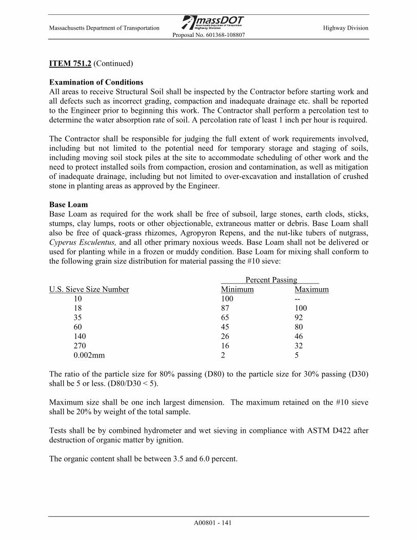
Massachusetts Department of Transportation Highway Division Proposal No. 601368-108807
A00801 - 141
ITEM 751.2 (Continued) Examination of Conditions All areas to receive Structural Soil shall be inspected by the Contractor before starting work and all defects such as incorrect grading, compaction and inadequate drainage etc. shall be reported to the Engineer prior to beginning this work. The Contractor shall perform a percolation test to determine the water absorption rate of soil. A percolation rate of least 1 inch per hour is required. The Contractor shall be responsible for judging the full extent of work requirements involved, including but not limited to the potential need for temporary storage and staging of soils, including moving soil stock piles at the site to accommodate scheduling of other work and the need to protect installed soils from compaction, erosion and contamination, as well as mitigation of inadequate drainage, including but not limited to over-excavation and installation of crushed stone in planting areas as approved by the Engineer. Base Loam Base Loam as required for the work shall be free of subsoil, large stones, earth clods, sticks, stumps, clay lumps, roots or other objectionable, extraneous matter or debris. Base Loam shall also be free of quack-grass rhizomes, Agropyron Repens, and the nut-like tubers of nutgrass, Cyperus Esculentus, and all other primary noxious weeds. Base Loam shall not be delivered or used for planting while in a frozen or muddy condition. Base Loam for mixing shall conform to the following grain size distribution for material passing the #10 sieve: Percent Passing U.S. Sieve Size Number Minimum Maximum 10 100 --
18 87 100 35 65 92 60 45 80 140 26 46 270 16 32 0.002mm 2 5
The ratio of the particle size for 80% passing (D80) to the particle size for 30% passing (D30) shall be 5 or less. (D80/D30 < 5). Maximum size shall be one inch largest dimension. The maximum retained on the #10 sieve shall be 20% by weight of the total sample. Tests shall be by combined hydrometer and wet sieving in compliance with ASTM D422 after destruction of organic matter by ignition. The organic content shall be between 3.5 and 6.0 percent.

Massachusetts Department of Transportation Highway Division Proposal No. 601368-108807
A00801 - 142
ITEM 751.2 (Continued) Sand Sand for Sand-Based Structural Soil, for Planting Pit Medium, for amending loam shall be uniformly graded medium to coarse sand consisting of clean, inert, rounded grains of quartz or other durable rock free from loam or clay, surface coatings and deleterious materials with the following gradation. Percent Passing U.S. Sieve Size Number Minimum Maximum
10 100 -- 18 60 80 35 25 45 60 8 20 140 0 8 270 0 3 0.002mm 0 0.5
Maximum size shall be one inch largest dimension. The maximum retained on the #10 sieve shall be 10% by weight of the total sample. The ratio of the particle size for 70% passing (D70) to the particle size for 20% passing (D30) shall be 3.0 or less. (D70/D20 <3.0) Tests shall be by combined hydrometer and wet sieving in compliance with ASTM D422 after destruction of organic matter by ignition. Organic Amendment Materials (Compost) Compost for amending planting media shall be a stable, humus-like material produced from the aerobic decomposition of organic residues. The residues, if biosolids, shall consist of compost meeting the required criteria as listed herein this Section or approved equal. The compost shall be a dark brown to black color and be capable of supporting plant growth with appropriate management practices in conjunction with addition of fertilizer and other amendments as applicable, with no visible free water or dust, with no unpleasant odor, and meeting the following criteria as reported by the producer. The ratio of carbon to nitrogen shall be in the range of 10:1 to 25:1. Stability shall be assessed by either a CO2 evolution test, a re-heating test, or the Solvita procedure. Protocols for each are specified by the coalition of Northeastern Governors Source Reduction Task Force (CONEG) in their 1966 report, "Model Procurement Specifications for Source Separated Compost." and the Solvita manual (version 3.5). For the CO2 test, the compost respiration shall be no more than 6 mg CO2-C/gBVS day. For re-heating using the Dewar self-heating test, the maximum heat rise shall be no greater than 48 degrees F above room temperature (68 to 77 degrees F). For the Solvita test, the compost must achieve a maturity index of 6 or more. Stability tests shall be conducted by Woods End Research Laboratory, Mt. Vernon, Maine.

Massachusetts Department of Transportation Highway Division Proposal No. 601368-108807
A00801 - 143
ITEM 751.2 (Continued) Pathogens/Metals/Vector Attraction reduction shall meet 40 CFR Part 503 rule, Table 3, page 9392, Vol. 58 No. 32, and Commonwealth of Massachusetts 310 CMR 32.00 (for applications to soils with human activity). Organic Content shall be at least 40 percent (dry weight). One hundred percent of the material shall pass a 3/8-inch (or smaller) screen. Debris such as metal, glass, plastic, wood (other than residual chips), asphalt or masonry shall not be visible and shall not exceed one percent dry weight. Organic content shall be determined by weight loss on ignition for particles passing a number 10 sieve according to procedures performed by a soil testing agency recommended by the Ohio State University Extension Program and approved by the Landscape Architect and Department. A 3 cubic inch sub-sample of the screened and mixed compost is ground to pass the number 60 sieve. 0.07 to 0.10 ounces of ground sample, dried to a constant weight at 221 degrees F is placed into a muffle furnace. The temperature is slowly raised (41 degrees F/minute) to 842 degrees F and maintained for three hours. The sample is removed to an oven to equilibrate at 224F and the weight is taken. Organic matter is calculated as loss on ignition. PH: The pH shall be between 5.5 to 8.0 as determined from a 1:1 soil-distilled water suspension using a glass electrode pH meter American Society of Agronomy Methods of Soil Analysis, Part 2, 1986. Salinity: Electrical conductivity of a one to two soil to water ratio extract shall not exceed 2.0 mmohs/cm (dS/m). The compost shall be screened to 3/8 inch maximum particle size and shall contain not more that 3 percent material finer that the 200 Sieve as determined by hydrometer test on ashed material. Nutrient content shall be determined by the University of Massachusetts Soil Testing Laboratory or equivalent laboratory and utilized to evaluate soil required amendments for the mixed soils. Chemical analysis shall be undertaken for Nitrate Nitrogen, Ammonium Nitrogen, Phosphorus, Potassium, Calcium, Aluminum, Magnesium, Iron, Manganese, Lead, Soluble Salts, Cation Exchange Capacity, soil reaction (pH), and Soil Additives Acidulant for adjustment of Structural Soil and Planting Pit Medium pH shall be commercial grade flours of sulphur, ferrous sulfate, or aluminum sulfate that are unadulterated. Acidulants shall be delivered in unopened containers with the name of the manufacturer, material, analysis and net weight appearing on each container. Ground limestone for adjustment of Structural Soil pH shall contain not less than 85 percent of total carbonates and shall be ground to such fineness that 40 percent will pass through 100 mesh sieve and 95 percent will pass through a 20 mesh sieve.
Massachusetts Department of Transportation Highway Division Proposal No. 601368-108807
A00801 - 144
ITEM 751.2 (Continued) Planting Fertilizer Commercial fertilizer for use in Structural Soil shall be a product complying with the State and United States fertilizer laws. Deliver fertilizer to the site in the original unopened containers, which shall bear the manufacturer's certificate of compliance covering analysis, which shall be furnished to the Engineer. Fertilizer shall be free of nitrogen with percentages of weight for phosphorus and potassium as recommended by soil testing and analysis. Phosphorus and potassium shall be added to the top 18 inches of the Structural Soil in 6-inch lifts as the Structural Soil is placed. Rototill fertilizer into each successive 6-inch lift. Structural Soil shall be sampled and tested after application of fertilizer to verify that amended Structural Soil meets the requirements of the soil test analysis recommendations. Submit soil test results to the Engineer for review and approval. Execution Sub-surface Conditions Notify the Engineer of subsurface conditions, which will affect the Contractor’s ability to complete the work. Locate and confirm the location of all underground utility lines and structures prior to the start of any excavation. The Contractor shall exercise extreme care and caution when excavating around existing utilities and shall repair any underground utilities or foundations damaged by the Contractor during the progress of this work. The cost of all repairs shall be at the Contractor’s expense. Site Preparation Do not proceed with the installation of the Structural Soil material until all walls, curb footings and utility work in the area has been installed. For site elements dependent on Structural Soil for foundation support, postpone installation until immediately after the installation of Structural Soil. Excavate and compact the proposed subgrade to depths, slopes and widths as shown on the Contract Documents. Maintain all required angles of repose of the adjacent materials as shown on the Contract Documents. Do not over excavate compacted subgrades of adjacent pavement or structures unless as directed by the Engineer. Confirm that the subgrade is at the proper elevation and compacted as required. Subgrade elevations shall slope parallel to the finished grade and or toward the subsurface drain lines as shown on the Contract Documents. Clear the excavation of all construction debris, trash, rubble and any foreign material. In the event that fuels, oils, concrete washout silts or other material harmful to plants has been spilled into the subgrade material, excavate the soil sufficiently to remove the harmful material. Fill any over excavation with approved fill and compact to the required subgrade compaction.
Massachusetts Department of Transportation Highway Division Proposal No. 601368-108807
A00801 - 145
ITEM 751.2 (Continued) Protect adjacent walls, walks and utilities from damage or staining by the soil. Use plywood and or plastic sheeting as directed to cover existing concrete, metal and masonry work and other items as directed during the progress of the work. Clean up all trash and any soil or dirt spilled on any paved surface at the end of each working day. Any damage to the paving caused by the soils installation contractor shall be repaired by the General Contractor at the General Contractor’s expense. Maintain all silt and sediment control devices required by applicable regulations. Provide adequate methods to assure that trucks and other equipment do not track soil from the site onto adjacent property and the public right of way. Planting Media Mix Design Mix Design: Sand-Based Structural Soil The Sand-Based Structural Soil shall consist of a blend of five parts by volume of Sand, one part by volume of Base-Loam and two parts by volume of Organic Amendment. Blending of the components shall be carried out with earth moving equipment prior to placement. The components shall be blended to create a uniform mixture as determined by the Engineer. The final mix shall have an organic content between 2.5 and 3.5 percent and conform to the following gradation requirements for material passing a Number 10 sieve. The Structural Soil design mix shall meet the following criteria: Percent Passing U.S. Sieve Size Number Minimum Maximum
10 100 -- 18 68 90
35 38 63 60 18 39 140 9 18 270 4 9 .002mm 1 2 Maximum size shall be one inch largest dimension. The maximum retained on the #10 sieve shall be 15% by weight of the total sample. The ratio of the particle size for 70% passing (D70) to the particle size for 20% passing (D20) shall be 3.5 or less. (D70/D20 <3.5) Tests shall be by combined hydrometer and wet sieving in compliance with ASTM D422 after destruction of organic matter by ignition.

Massachusetts Department of Transportation Highway Division Proposal No. 601368-108807
A00801 - 146
ITEM 751.2 (Continued) Mix Design: Planting Pit Medium Planting pits shall be backfilled around trees with a blend of two parts by volume of Sand, to one part by volume Base Loam, and one part by volume Organic Amendment. Blending of the components shall be carried out with earth moving equipment prior to placement. The components shall be blended to create a uniform mixture as determined by the Engineer. The final mix shall have an organic content between 4 and 7 percent and conform to the following gradation requirements for material passing a Number 4 sieve. The Planting Pit mix shall meet the following criteria: Percent Passing U.S. Sieve Size Number Minimum Maximum
10 100 -- 18 73 93
35 55 82 60 28 51 140 18 27 270 11 18 .002mm 1 4 Maximum size shall be one inch largest dimension. The maximum retained on the #10 sieve shall be 20% by weight of the total sample. The ratio of the particle size for 80% passing (D70) to the particle size for 30% passing (D30) shall be 4.0 or less. (D80/D30 <4.0) Tests shall be by combined hydrometer and wet sieving in compliance with ASTM D422 after destruction of organic matter by ignition. Placement of Sand-Based Structural Soil Contractor shall obtain Engineer’s written approval of previously completed work of rough grading of subsoil prior to commencing loam borrow or Structural Soil placement work. Immediately prior to dumping and spreading the Structural Soil, the subgrade shall be cleaned of all debris or rubbish. Such material shall be removed from the site. After subgrade levels have been reached, and immediately prior to placing Sand-Based Structural Soil the entire subgrade area shall be thorough compacted, then loosened to a minimum depth of four inches utilizing the teeth on the bucket of a backhoe or by deep raking.

Massachusetts Department of Transportation Highway Division Proposal No. 601368-108807
A00801 - 147
ITEM 751.2 (Continued) After loosening, Sand-Based Structural Soil shall be spread in lifts not greater than eight inches and compacted with a minimum of two passes of vibratory compaction equipment to a density between 90 and 94 percent Standard Proctor Maximum Dry Density in accordance with compaction standards of ASTM D1557 Method D. During the compaction process, all depressions caused by settlement or compaction shall be filled with additional Structural Soil and the surface shall be regraded and rolled until presenting a smooth and even finish corresponding to the required grades. Sand-Based Structural Soil shall be placed to a depth of two feet within the areas shown on the Drawings. Phase the installation of the Structural Soil such that wheeled equipment does not have to travel over already installed soil. If it is determined by the Engineer that equipment must travel over already installed Structural Soil, provide one- inch thick steel plate ballast over the length and width of travel to cover Structural Soil and protect it from compaction. Planting The Contractor shall follow standard planting procedures for deciduous trees as specified, provided, installed, and paid for under Section, PLANTING, unless otherwise noted herein. Placement of Planting Pit Medium in Tree Pits: After subgrade levels have been reached in tree pits, a minimum of four inches of Sand-Based Structural Soil shall be placed and compacted as a base for the root ball. After setting root balls in accordance with Section PLANTING, tree pits shall be backfilled with Planting Medium Pit as described in this Section in six inch lifts and tamped to 84 to 88 percent Modified Proctor Maximum Dry Density. The surface area of each lift shall be scarified by raking prior to placing the next lift. All plants shall be watered immediately following placement in their final locations as necessary to thoroughly moisten rootball and planting pit medium and thereafter shall be inspected frequently for watering needs and watered, as required, to provide adequate moisture in the planting pit and in the Structural Soil. The Contractor shall inspect tree pits in plant bed 24 hours after initial watering to confirm that they are draining properly. If surface water or excessively saturated plant pit soils exist, the Contractor shall immediately notify the Engineer. The Engineer will recommend remedial measures based upon site conditions.
Massachusetts Department of Transportation Highway Division Proposal No. 601368-108807
A00801 - 148
ITEM 751.2 (Continued) Acceptance Standards The Engineer will inspect the work upon the request of the Contractor. Request for inspection shall be received by the Engineer at least 10 Days before the anticipated date of inspection. Acceptance, Maintenance, and Guarantee shall be in accordance with Section PLANTING. Clean-Up Upon completion of the Structural Soil installation operations, clean areas within the contract limits. Remove all excess fills, soils and mix stockpiles and legally dispose of all waste materials, trash and debris. Remove all tools and equipment and provide a clean, clear site. Sweep, do not wash, all paving and other exposed surfaces of dirt and mud until the paving has been installed over the Structural Soil materials. Do no washing until finished material covering Structural Soil is in place. Method of Measurement Item 751.2 will be measured per Cubic Yard of soil installed, complete-in-place. Basis of Payment Item 751.2 will be paid for at the contrac unit price per Cubic Yard. This price shall include complete compliance with requirements of this item, including providing testing, amending, excavation, placing, spreading, material, compacting, fine grading, labor, materials, equipment, and incidentals necessary to complete the work. ITEM 756. NPDES STORM WATER POLLUTION PREVENTION PLAN LUMP SUM This Item addresses the preparation and implementation of a Storm Water Pollution Prevention Plan required by the National Pollutant Discharge Elimination System (NPDES) and applicable Construction General Permit (CGP) issued by the U.S. Environmental Protection Agency (EPA). Pursuant to the Federal Clean Water Act, construction activities which disturb one acre or more are required to apply to the EPA for coverage under the NPDES General Permit for Storm Water Discharges from Construction Activities. On February 16, 2012 (77 FR 12286), EPA issued the final NPDES Construction General Permit (CGP) for construction activity. The Contractor shall be fully responsible for compliance with the CGP. Should a fine or penalty be assessed against it, or MassDOT, as a result of a local, state, or federal enforcement action due to non-compliance with the CGP, the Contractor shall take full responsibility. The NPDES CGP requires the submission of a Notice of Intent (NOI) to the EPA prior to the start of construction (defined as any activity which disturbs land, including clearing and grubbing). There is a fourteen (14) day review period commencing from the date on which EPA enters the Notice into their database. The Contractor is advised that, based on the review of the NOI, EPA may require additional information, including but not limited to, the submission of the Storm Water Pollution Prevention Plan (SWPPP) for review. Work may not commence on the project until final authorization has been granted by EPA. Any additional time required by EPA for review of submittals will not constitute a basis for claim of delay.

Massachusetts Department of Transportation Highway Division Proposal No. 601368-108807
A00801 - 149
ITEM 756. (Continued) In addition, if the project discharges to an Outstanding Resource Water, vernal pool, or is within a coastal ACEC as identified by the Massachusetts Department of Environmental Protection (DEP), a separate notification to DEP is required. DEP may also require submission of the Storm Water Pollution Prevention Plan for review and approval. Filing fees associated with the notification to DEP and, if required, the SWPPP filing to DEP shall be paid by the Contractor. The CGP also requires the preparation and implementation of a SWPPP in accordance with the afore-mentioned statutes and regulations. The Plan will include the CGP conditions and detailed descriptions of controls of erosion and sedimentation to be implemented during construction. It is the responsibility of the Contractor to prepare the SWPPP to meet the requirements of the most recently issued CGP. The Contractor shall submit the Plan to the Engineer for approval at least four (4) weeks prior to any site activities. It is the responsibility of the Contractor to comply with the CGP conditions and the conditions of any state Wetlands Protection Act Order, Water Quality Certification, Corps of Engineers Section 404 Permit and other environmental permits applicable to the project and to include in the SWPPP the methods and means necessary to comply with applicable conditions of said permits (reference to Part 9.1.1 of the 2012 CGP). It is the responsibility of the Contractor to complete the SWPPP in accordance with the EPA CGP, provide all information required, and obtain any and all certifications as required by the CGP. Any amendments to the SWPPP required by site conditions, schedule changes, revised work, construction methodologies, and the like are the responsibility of the Contractor. Amendments will require the approval of the Engineer prior to implementation. Included in the CGP conditions is the requirement for inspection of all erosion controls and site conditions on a weekly basis as well as after each incidence of rainfall exceeding 0.25 inches in twenty-four hours. For multi-day storms, EPA requires that an inspection must be performed during or after the first day of the event and after the end of the event. The CGP requires that inspections be performed by a qualified individual. MassDOT requires proof of completion of a 4 hour minimum sedimentation and erosion control training class current to the latest CGP. This individual can be, but not limited to, someone that is either a certified inspector, certified professional, or certified storm water inspector. The documentation shall be included as an appendix in the SWPPP. The Engineer must approve the contractor’s inspector. This individual shall be on-site during construction to perform these inspections. In addition, if the Engineer determines at any time that the inspector’s performance is inadequate, the Contractor shall provide an alternate inspector. Written weekly inspection forms, storm event inspection forms, and Monthly Summary Reports must be completed and provided to the Engineer. Monthly Summary Reports must include a summary of construction activities undertaken during the reporting period, general site conditions, erosion control maintenance and corrective actions taken, the anticipated schedule of construction activities for the next reporting period, any SWPPP amendments, and representative photographs.
Massachusetts Department of Transportation Highway Division Proposal No. 601368-108807
A00801 - 150
ITEM 756. (Continued)
The Contractor is responsible for preparation of the Plan, all SWPPP certifications, inspections, reports and any and all corrective actions necessary to comply with the provisions of the CGP. Work associated with performance of inspections is not included under this Item. The Standard Specifications require adequate erosion control for the duration of the Contract. All Control measures must be properly selected, installed, and maintained in accordance with manufacturer specifications and good engineering practices. If periodic inspections or other information indicates a control has been used inappropriately or is no longer adequate, it is the responsibility of the Contractor to replace or modify the control for site conditions at no additional cost to the Department. Contractor must maintain all control measures and other protective measures in effective operating condition and shall consider replacement of erosion controls for each construction season.
This Item addresses acceptable completion of the SWPPP, any revisions/amendments required during construction, and preparation of monthly reports. In addition, any erosion controls beyond those specified in bid items elsewhere in this contract which are selected by the Contractor to facilitate and/or address the Contractor’s schedule, methods and prosecution of the work shall be considered incidental to this item.
The Contractor is advised The CGP provides specific requirements for temporary and final stabilization. This shall be incorporated into the project schedule. The permit defines specific deadline requirements for Initial Stabilization (“immediately”, i.e., no later than the end of the next work day following the day when earth-disturbing activities have temporarily or permanently ceased) and for Complete Stabilization Activities (no later than 14 calendar days after the initiation of stabilization). Stabilization criteria for vegetative and non-vegetative measures are provided in the CGP.
The CGP requires the submission of a Notice of Termination (NOT) from all operators when final stabilization has been achieved, as well as removal and proper disposal of all construction materials, waste and waste handling devices, removal of all equipment and construction vehicles, removal of all temporary stormwater controls, etc. . Approval of final stabilization by the Engineer and confirmation of submission of the NOT will be required prior to submission of the Resident Engineer’s Final Estimate. The permittee is required to use EPA’s electronic NOI system or “eNOI system” to prepare and submit NOT. The electronic NOT form can be found at https://www.epa.gov/npdes/stormwater-discharges-construction-activities#ereporting . If you are given approval by the EPA Regional Office to use a paper NOT, you must complete the form in Appendix K of the 2012 CGP.
Compensation Payment for all work under this Item shall be made at the contract unit price, lump sum, which shall include all work detailed above, including Plan preparation, required revisions, revisions/addenda during construction, monthly reports and filing fees. Payment of fifty (50) % of the contract price shall be made upon acceptance of the Stormwater Pollution Prevention plan. Payment of forty (40) % of the contract price shall be made in equal installments for implementation of the Stormwater Pollution Prevention plan. Payment of the final ten (10) % of the contract price shall be paid upon satisfactory submissions of a Notice of termination (NOT) when final stabilization has been achieved.

Massachusetts Department of Transportation Highway Division Proposal No. 601368-108807
A00801 - 151
ITEM 772.023 PEAR – CALLERY-‘CHANTICLEER’ 2.5-3 INCH CALIPER EACH ITEM 775.030 ELM-‘ACCOLADE’ 2.5-3 INCH CALIPER EACH ITEM 786.463 JUNIPER –SARGENT 18-24 INCH EACH ITEM 789.815 CINQUEFOIL – ABBOTTSWOOD 18- 24 INCH EACH ITEM 789.833 CINQUEFOIL – KATHERINE DYKES 18- 24 INCH EACH ITEM 794.335 SUMAC SHRUB-FRAGRANT ‘GRO-LOW’ 18-24 INCH EACH ITEM 796.421 PRAIRIE DROPSEED 2 GALLON EACH ITEM 796.749 DAYLILY-‘FRANS HALS’ 1 GALLON EACH ITEM 796.761 DAYLILY-‘HAPPY RETURNS’ 1 GALLON EACH ITEM 796.762 DAYLILY-‘ROSY RETURNS’ 1 GALLON EACH The work under these items shall conform to the relevant provisions of the American Nursery Standards, Section 771 of the Standard Specifications, and the following: The work shall include furnishing and installing all trees and hedges as shown on the Plans. The work shall include excavation of pits, furnishing and placing of planting mix, mulches, fertilizer and all other pertinent materials as described in Section 771 of the Standard Specification or as defined in the details. The Contractor shall provide and install plant material of genus, species, variety, size and quantities in locations as directed by the City’s Park Department or designee. The work includes the following:
• Purchasing and transporting plant material to the Contract site • Installation of plant material • Plant care during sixty (60) day Maintenance Period and one-year Establishment Period • Replacement of defective or dead plant at End of Maintenance Period. • Replacement of defective or dead plant at End of Establishment Period.
The Contractor shall contract the City prior to ordering plants to coordinate the plant selections. The City will send a representative to the nursery to inspect plantings. Also, the City Park Department will oversee the planting of roundabout central island. Method of Measurement and Basis of Payment Items 772.023 through 796.762 will be measured and paid per Subsections 771.80 and 771.81, respectively.
Massachusetts Department of Transportation Highway Division Proposal No. 601368-108807
A00801 - 152
ITEM 804.2 2 INCH ELECTRICAL CONDUIT TYPE NM - PLASTIC - (UL) FOOT The work under this item shall conform to the relevant portions of Section 801 of the Standard Specifications and the following: The work shall include the furnishing and the installation of 2 inch non-metallic conduit for the street lighting system in accordance with the plans and as required by the Engineer. Rigid Plastic Conduit Conduit of the sizes shown on the DRAWINGS shall be new gray heavy wall rigid plastic conduit of homogenous polyvinyl chloride construction with standard wall thickness. The conduit shall conform to UL Standards for Schedule 40 Type EPC Conduit. Couplings and Fittings Conduit couplings shall be constructed of polyvinyl chloride rigid plastic formed to fit the outside diameter of the conduit, to be used in conjunction with heavy-bodied solvent cement. ASTM Specification D2564 Solvent Cements for PVC Plastic Pipe and Fittings Conduit Duct Bell Ends shall be polyvinyl chloride rigid plastic approved by Underwriter’s Laboratories, Inc. for use on threadless rigid plastic conduit, to be used in conjunction with a heavy bodied solvent cement. Construction Methods The PVC conduit shall be installed in a trench as described in Section 801.60 of the Standard Specification. Refer to trench details for backfill requirements and warning tape requirements above the PVC conduits. A 3/4-inch polypropylene pull rope shall be installed in all conduits. The conduit shall be concrete encased with 3 inches on all sides when crossing streets. Concrete encasement when running parallel to roadway surface is not required. Conduits entering concrete pull boxes or electric manholes shall be terminated 2 inches inside the wall of the pull box and shall have attached a bell end of the required size, using the solvent cement as called for in the specifications. All conduit installed in pull boxes or electric manholes shall be installed in knockouts provided in the box. After the conduit has been installed in the pull box or electric manholes, the open space between the box or manhole and the conduit will be sealed with Class B Cement Concrete Masonry. Any conduit installed in such a manner as to block complete access to any other conduit shall be removed and reset. Method of Measurement and Basis of Payment Item 804.2,will be measured and paid for per Subsections 801.80 and 801.81, respectively. When required, Controlled Density Fill-Excavatable will be paid for under Item 153.
Massachusetts Department of Transportation Highway Division Proposal No. 601368-108807
A00801 - 153
ITEM 803.3 3 INCH ELECTRICAL CONDUIT FOOT TYPE NM PLASTIC (UL) ITEM 804.4 4 INCH ELECTRACTICAL CONDUIT FOOT
TYPE NM PLASTIC (UL) The work under these items shall conform to the relevant provisions of Section 801 of the Standard Specifications, the City of Worcester Standard Specifications, and the following: The work shall include the furnishing and installing a 3-inch non-metallic conduit for traffic signal systems, interconnect, and future use and a 4-inch non-metallic conduits for fiber-optic conduit between the controller cabinet and the adjacent handhole in accordance with the plans and as required by the Engineer. Two 3-inch conduit shall be installed side by side in the same trench. The conduit material shall be Schedule 80 polyvinyl chloride (PVC) plastic conduit. Where conduit is installed in existing sidewalk or paved median areas to remain, the work shall include replacement of the gravel base material and the surface pavement to match preconstruction conditions. No separate payment will be made for this work, but all costs in connection therewith shall be included in the unit price bid. Where conduit is installed in cold plane and overlaid pavement, trenches shall be sawcut through their full depth and the pavement removed. The conduit shall be placed on a sand bed and backfilled with excavatable controlled density fill. All conduits crossing the roadway and driveways shall be a minimum of 3 feet deep. Backfill material shall consist of gravel base material. Method of Measurement Items 803.3 and 804.4 will be measured for payment per Subsection 801.80. Basis of Payment Items 803.3 and 804.4 will be paid for per Subsection 801.81. Controlled Density Fill-excavatable will be paid for under Item 153.
Massachusetts Department of Transportation Highway Division Proposal No. 601368-108807
A00801 - 154
ITEM 804.35 3 INCH ELECTRICAL CONDUIT (CONDUIT ONLY) FOOT The work under this Item shall conform to the relevant provisions of Section 801 of the Standard Specifications, the City of Worcester Standard Specifications Section 800, and the following: The work shall include furnishing and installing an additional 3-inch non-metallic conduit for future traffic signal systems, interconnects, and general communications use. This conduit shall be placed within the same trench of and at the same elevation as the conduit installed under Item 804.3. The conduit shall be spaced 3 inches from the wall of the trench and 3 inches from the conduit installed under Item 804.3. A polypropylene pull rope sized to properly support the installation of required communications wire/fiber optics shall be installed in all conduits. The conduit material shall be Schedule 80 polyvinyl chloride (PVC) plastic conduit. All sawcutting, excavation, ordinary borrow, gravel borrow, warning tape, sand bedding, all labor, materials, equipment and incidental costs required to complete the work are subsidiary under Item 804.3 and no additional payments will made under this item. Method of Measurement Item 804.25 will be measured per Subsection 801.80. Basis of Payment Item 804.35 will be paid per Subsection 801.81.
Massachusetts Department of Transportation Highway Division Proposal No. 601368-108807
A00801 - 155
ITEM 806.2 2-INCH ELECTRICAL CONDUIT TYPE RM - FOOT GALVANIZED STEEL The work under this item shall conform to the relevant portions of Section 801 of the Standard Specifications and the following: The work shall include the furnishing and the installation of 2-inch Type RM Steel conduit in accordance with the plans and as required by the Engineer. Conduit Conduit of the sizes shown on the DRAWINGS shall be new heavy wall rigid steel galvanized. The conduit shall conform to UL Standards for Rigid Metal Conduit. Couplings and Fittings Conduit couplings and fittings shall be threaded. Construction Methods The conduit shall be installed in a trench as described in Subsection 801.60 of the Standard Specifications. Refer to trench details for backfill requirements and warning tape requirements above the conduits. A ¾-inch polypropylene pull rope shall be installed in all conduits. Conduits entering concrete pull boxes or electric manholes shall be terminated 2 inches inside the wall of the pull box and shall have attached a bell end of the required size, using the solvent cement as called for in the specifications. All conduit installed in pull boxes or electric manholes shall be installed in knockouts provided in the box. After the conduit has been installed in the pull box or electric manholes, the open space between the box or manhole and the conduit will be sealed with Class B Cement Concrete Masonry. Any conduit installed in such a manner as to block complete access to any other conduit shall be removed and reset. Method of Measurement Item 806.2 will be measured per Subsection 801.80 Basis of Payment Item 806.2 will be paid per Subsection 801.81. Controlled density fill will be paid for under Item 153.

Massachusetts Department of Transportation Highway Division Proposal No. 601368-108807
A00801 - 156
ITEM 811.22 ELECTRIC HANDHOLE – SD2-.022 EACH The work under this item shall conform to the relevant provisions of Section 801 of the Standard Specifications and the following: The work shall include the furnishing and installation of pull boxes, frames, and covers for the fiber optic interconnect system in accordance with the plans and as directed by the Engineer. Pull boxes associated with traffic signals shall have “TRAFFIC” embossed on the cover per City of Worcester standards. Method of Measurement Item 811.30 will be measured for per Subsection 801.80. Basis of Payment Item 811.22 will be paid per Subsection 801.81. ITEM 811.30 PULL BOX 8 X 23 INCHES - SD2.030 EACH The work under this item shall conform to the relevant portions of Section 801 of the Standard Specifications and the following: The work includes furnishing and installing pull boxes for the lighting system in accordance with the plans and as required by the Engineer. Materials MassDOT standard pre-cast concrete hand hole. Cover: MassDOT standard cast-iron frame and cover plate except notation on cover shall be “LIGHTING”. A 5/8” diameter x 8 ft long copper clad steel ground rod shall be installed in each handhole and connected to the equipment grounding conductors from all circuits entering the handhole. All covers shall be bonded to ground rod. Method of Measurement Item 811.30 will be measured for per Subsection 801.80. Basis of Payment Item 811.30 will be paid per Subsection 801.81.
Massachusetts Department of Transportation Highway Division Proposal No. 601368-108807
A00801 - 157
ITEM 812.09 LIGHT STANDARD FOUNDATION PRECAST EACH The work under this item shall conform to the relevant provisions of Section 801 of the Standard Specifications and the following: The work includes furnishing and installing various types and sizes of precast light standard foundations at the locations shown on the plans and as required by the Engineer. Materials The details of the precast foundations are indicated on the drawings included as part of the Contract specifications. Concrete: Shall be Type III PSI: Shall be 5,000 PSI @ 28 days. Rebar: Shall be Grade 60 per ASTM A615 Green Epoxy Construction Methods All foundations shall be installed at the location as shown on the plan except as approved deviations are required to meet field conditions. All foundations will be set plumb and true to grade. All foundations shall be installed to a depth as shown on the plans and details. The Contractor shall carefully mark the proposed location of the foundations and then the contractor shall determine if any utilities or underground or overhead obstruction will prevent the installation at each location. Similar marking shall be done for the conduit runs to the foundation. If an obstruction is evident the Contractor shall request permission from the Engineer to move or adjust the location of the foundation. If no obstruction is apparent at the proposed foundation location the Contractor shall make an opening deep and wide enough to accommodate the foundation, this task shall be accomplished with hand digging. Mechanical excavating equipment shall be used if approved by the Engineer; however, if this means is used, the Contractor shall provide a six (6) inch cushion of gravel borrow under the foundation and shall backfill using gravel borrow well tamped in six (6) inch layers around the foundation. A compaction of 95% for distance of five (5) feet around the foundation is required. The backfill shall be thoroughly compacted by tamping with a pneumatic hammer equipped with a round dirt tamping pad with a minimum diameter of six (6) inches driven by an air compressor with a minimum of 100 psi pressure.
Massachusetts Department of Transportation Highway Division Proposal No. 601368-108807
A00801 - 158
ITEM 812.09 (Continued) The use of an impactor attachment on a standard backhoe with a dirt tamping pad shall substitute for the pneumatic hammer with the permission of the Engineer. Use of a vibrator type compactor around the pre-cast subbase or pull box is prohibited. If the Contractor encounters no difficulty in the excavation and the soil conditions are suitable to support the foundation, the Contractor shall install the foundations. The top of the foundation shall be level and installed as indicated on the plans. After the installation of the street light foundation, the Contractor shall cap the end of the exposed conduit. On straight sections of curb, the bolts shall be parallel with the face of the curb. On curved sections, the bolts shall be adjusted to allow proper placement of the bracket and luminaire on the pole into the roadway when installed. Placement of the foundation predetermines the placement of the bracket arm, as only a minor adjustment of the pole on the foundation can be accomplished when the pole is installed. Junction Box Cover shall be installed per manufacturer’s directions or as required by the Engineer. Method of Measurement Item 812.09 will be measured for payment per Each precast standard light foundation, complete in place. Basis of Payment Item 812.09 will be paid for at the contract unit price per Each, which price shall include all labor, material, equipment, excavation, back filling, gravel borrow, and incidental costs required to complete the work.

Massachusetts Department of Transportation Highway Division Proposal No. 601368-108807
A00801 - 159
ITEM 813.30 WIRE TYPE 7 NO. 10 GENERAL PURPOSE FOOT ITEM 813.32 WIRE TYPE 7 NO. 6 GENERAL PURPOSE FOOT The work under these items shall conform to the relevant provisions of Section 813 of the Standard Specifications and the following: The work includes furnishing and the installing wiring systems for the street lighting system in accordance with the plans and as required by the Engineer. Materials
Description: Single conductor insulated wire, stranded (for No. 6), solid (for No. 10). Conductor: Copper. Insulation: ANSI/NFPA 70, Type RHW without overall jacket.
Installation The Contractor shall:
• Pull all conductors into raceway at same time.
• Use suitable cable fittings and connectors.
• Neatly train and lace wiring inside boxes, equipment, and panelboards.
• Make splices, taps, and terminations to carry full ampacity of conductors with no perceptible temperature rise.
• Use gel-filled solderless pressure connectors with insulating covers for copper conductor splices and taps, 6 AWG and smaller.
Method of Measurement Items 813.30 and 813.32 will be measured for payment per Foot as specified in Subsection 813.80. Basis of Payment Items 813.30 and 813.32 will be paid for at the respective contract unit price per Foot, as specified in Subsection 813.81.

Massachusetts Department of Transportation Highway Division Proposal No. 601368-108807
A00801 - 160
ITEM 813.79 INTERCONNECT CABLE SYSTEM LUMP SUM The work under this Item shall conform to the relevant provisions of Section 800 of the Standard Specifications and the following: The work shall include modifying the existing traffic signal system master (TSSM), and furnishing and installing proposed fiber-optic interconnects, removing and discarding existing communication cables, and all appurtenances required to interface with the local intersection controllers. Modify TSSM The existing TSSM is housed in the traffic controller cabinet at Grafton Street at I-290 Ramps/CSX Driveway. Note: This intersection was reconstructed by others in 2012. The Contractor shall perform necessary cabinet work to implement proposed fiber-optic interconnect cables and coordination as shown on the plans. Contractor shall upgrade the existing Siemens m50 TSSM software and/or firmware to ensure it is fully compatible with the new traffic signal controllers connected to the TSSM. The existing FSK (serial) communications between the TSSM and the local controllers shall be removed and replaced with IP based communications utilizing the new fiber optic cable and Ethernet switches. The Contractor shall request from the City and/or the Engineer the IP address information for the TSSM. Interconnect Cable System The Contractor shall furnish and install a complete underground traffic interconnect cable system in existing/ proposed conduit, including wiring, grounding and incidental work between traffic signal controllers. Reference is made to the general plans included in the contract documents. The cable run shall be installed as follows: Along the Grafton Street corridor between the traffic controller cabinet at Franklin Street and the traffic controller cabinet at Wall Street via the traffic controller cabinets at Winter Street/Water Street, at I-290 Ramps, and at Waverly Street. The interconnect fiber-optic cable shall be 12 single mode, outside plant loose tube. The cable shall utilize a single layer polypropylene tube and shall use absorbent polyester tape in place of gel for water blocking, and shall meet the following minimum requirements:
• Impedance of 600 ohms resistance and balance • Envelope delay distortion shall be less than 1750 microseconds in the band from 800 to
2600 Hz • Frequency response referred to 1000Hz from 300 to 3000Hz shall be flat-3, +12dB.
Response reference to 1000Hz from 500 t0 250Hz shsll be flat-2, +8dB • Insulation between any conductor ground shall be at least 20 meghoms DC and 50
Kohms AC from 300 to 3000Hz
Massachusetts Department of Transportation Highway Division Proposal No. 601368-108807
A00801 - 161
ITEM 813.79 (Continued)
• Capable of transmitting a signal of nor less than +10dBm (average) • Noise level shall be no more than -62dBm • Non-linear (harmonic distortion, fundamental to first harmonic of 25dB minimum,
fundamental to third harmonic of 30dB minimum • Breakdown between any conductor and ground shall be greater than 1500V rms at 60Hz • Minimum receiving level at most distant point shall be no less than -26dBm at 0dBm
input power. This work shall include properly terminating the new cable on existing and proposed splice panels, properly routing the cable in the cabinets, and performing any additional work necessary to provide a properly installed and operating fiber optic cable system into the existing/proposed traffic signal controller cabinets. Splices between controller cabinets shall not be allowed. The Contractor shall install a ten (10) foot minimum slack coil of the proposed fiber optic cable inside the existing/proposed controller cabinets. At all times during and after installation, diameter of slack coil shall be maintained at not less than twelve (12) inches. The fiber optic cable installed under this contract shall be identified with permanently attached plastic labels at each controller cabinet. The labels shall either be embossed or printed with permanent non-fading ink, indicating the name of the intersection that is at the other end of the cable and bearing the legend "TRAFFIC INTERCONNECT CABLE". The tags shall also be labeled with the location of the cable’s termination point. The Engineer shall approve the label format and attachment mechanism before label installation. The Contractor shall test the fiber optic cable prior to installation and again after all splicing and terminations have been completed. Testing shall be performed in the presence of the Design Engineer and the Resident Engineer. Basis of Payment Item 813.79 will be paid for at the contract Lump Sum price, which price shall include removing and discarding exiting interconnect cables, all labor, materials, equipment and incidental costs required to complete the work. Pull boxes for the fiber-optic interconnect system shall be paid for under Item 811.22. Three-inch conduit will be paid for under Item 804.3. Four-inch conduit will be paid for separately under Item 804.4.
Massachusetts Department of Transportation Highway Division Proposal No. 601368-108807
A00801 - 162
ITEM 813.81 SERVICE CONNECTION (UNDERGROUND) LUMP SUM The work under this item shall conform to the relevant portions of Section 813 of the Standard Specifications and the following: The work shall include the installing the electric service connections from the utility company point of service to the lighting control cabinets at Station 42+75 LT and Station 501+70 LT, in accordance with the plans and as directed by the Engineer. Construction Methods The Contractor shall coordinate service connections with the local utility company providing power to the area. Service connections shall conform to all utility company policies and practices. Service connections shall be coordinated and installed in accordance with the local utility company requirements as provided by the utility company. Each service shall include a three-wire single phase solid neutral service conductors, conduits, conduit risers, and splicing connections required to complete the installation. Meters will be furnished and installed by the local utility company. Basis of Payment Item 813.81 will be paid for at the contract unit bid price, Lump Sum, which price shall include all labor, material, tools and equipment, conduit, conductors, sweeps, bends, couplings, connectors, splices, sealing and waterproofing, for furnishing and installing conductors in conduit, and all incidental costs required to complete the work. ITEM 816.01 TRAFFIC SIGNAL RECONSTRUCTION LUMP SUM LOCATION NO. 1 ITEM 816.02 TRAFFIC SIGNAL RECONSTRUCTION LUMP SUM LOCATION NO. 2 ITEM 816.03 TRAFFIC SIGNAL RECONSTRUCTION LUMP SUM LOCATION NO. 3 ITEM 816.04 TRAFFIC SIGNAL RECONSTRUCTION LUMP SUM LOCATION NO. 4 ITEM 816.05 TRAFFIC SIGNAL RECONSTRUCTION LUMP SUM LOCATION NO. 5 ITEM 816.06 TRAFFIC SIGNAL RECONSTRUCTION LUMP SUM LOCATION NO. 6 ITEM 816.07 TRAFFIC SIGNAL RECONSTRUCTION LUMP SUM LOCATION NO. 7

Massachusetts Department of Transportation Highway Division Proposal No. 601368-108807
A00801 - 163
ITEM 816.01 through ITEM 816.07 (Continued) The work under these items shall conform to the relevant provisions of Section 815 of the Standard Specifications, City of Worcester DPW Standards Specifications & Details, and the following: The work includes furnishing and installing part or all of the following items:
• Modify local traffic signal controller and cabinet assembly; • Local traffic signal controllers, • Cabinets and foundation; • Mast arm poles with anchor bolts and foundations; • Signal posts and foundations; • Signal heads; backplates; • Pedestrian signals with countdown timers; • Video detection; wire loop detectors; • Aps pedestrian push buttons; • Emergency preemption; • Fiber optic patch panels; • All cable and wiring; • Ground rods, • Equipment grounding and bonding; • All other equipment, materials and incidental costs necessary to provide complete, fully
operational traffic control signal systems as specific herein and as shown on the plans. Locations The locations are as follows: • Location 1 – Grafton Street at Franklin Street (Item 816.01) • Location 2 – Grafton Street at Winter Street/ Water Street (Item 816.02) • Location 3 – Grafton Street at I-290 On/Off Ramp & CSX Driveway (Item 816.03) • Location 4 - Grafton Street at Waverly Street (Item 816.04) • Location 5 – Grafton Street at Wall Street/ Cutler Street (Item 816.05) • Location 6 – Plantation Street at Hamilton Street (Item 816.06) • Location 7 – Grafton Street at Plantation Street/ Acton Street/ Massasoit Road (Item 816.07) List of the major traffic signal items required at these locations are included on the plans.
Massachusetts Department of Transportation Highway Division Proposal No. 601368-108807
A00801 - 164
ITEM 816.01 through ITEM 816.07 (Continued) Shop Drawings Thirty days after the Norice to Proceed, the Contractor shall submit shop drawings for signal supports, a list of equipment, and manufacturer's equipment specifications to the City of Worcester in accordance with the relevant provisions of Section 815.20. The Contractor shall submit shop drawings for signal supports, a list of equipment, and manufacturer's equipment specifications to the Engineer in accordance with the relevant provisions of Section 815.20. The Contractor shall not begin work until approval of the shop drawings and manufacturer's data has been received in writing from the Engineer. Approval of these drawings will be general in character and shall not relieve the Contractor from the responsibility of, or the necessity of, furnishing materials and workmanship conforming to the plans and specifications. The Contractor shall deliver to the Engineer a certificate of compliance with the manufacturer for all materials purchased from the manufacturer. Existing Installations Some of the existing traffic signal equipment, conduit, and hand holes shall be retained under Items 816.01, 816.03, 816.04, 816.06 and 816.07 and in accordance with the relevant provisions of Subsection 815.65. Existing signal installation to be reconstructed/modified under Items 816.01, 816.02, 816.03, 816.04, 816.05, 816.06 and 816.07 shall be maintained in operation throughout the construction period and until the new signal is ready for operation. The Contractor may use temporary supports for signal heads as necessary to allow construction activities. Any temporary installations shall be in conformance with the MUTCD at all times. If an existing signal is to be turned off temporarily to allow controllers switch overs or rewiring, police detail shall be used to control traffic at the intersection. The Contractor shall carefully remove, transport and stack unused items of the old signals, at no additional compensation, to the City of Worcester’s Traffic Sign Shop located at 26 Albany Street, unless directed otherwise by the Engineer. The Contractor shall coordinate with the City of Worcester to schedule drop-off time. The Contractor shall remove and dispose of old cable and unusable materials and shall adhere to the regulations and requirements of local authorities governing the disposal of such material, at no additional compensation. Signal Turn-On Prior to initial turn-on of the new signals, equipment, signal displays, vehicle detection as shown on the plans and called for in these special provisions, shall be installed and operable. Applicable signs and pavement makings shall also be in place when the new signals are operational.

Massachusetts Department of Transportation Highway Division Proposal No. 601368-108807
A00801 - 165
ITEM 816.01 through ITEM 816.07 (Continued) Service Connections Service connection for Items 816.02 and 816.05 shown on the plans are approximate only. The Contractor shall determine exact locations from the servicing utility, arrange to complete the service connections early during the construction process, and be responsible for all charges incidental thereto. Service connections under Items 816.01, 816.03, 816.04, 816.06 and 816.07 shall be retained. Testing of Grounding System Under Items 816.02 and 816.05 the Contractor shall perform testing of the equipment grounding system in the presence of the Design Engineer in accordance with MassDOT Standard Specifications. Flashing Operation Changes from automatic flashing to stop-and-go operation and from stop-and-go to automatic flashing operation shall occur as set forth in the MUTCD. Traffic Signal Equipment The traffic signal controller units, malfunction management units, cabinet power supplies, bus interface units, and all other ancillary traffic signal control components included in the traffic control cabinets shall comply with the National Electrical Manufacturers Association (NEMA) Standard No. TS 2-2003 (R2008) v02.06, Traffic Controller Assemblies with National Transportation Communications for ITS Protocol (NTCIP) Requirements. Traffic Signal Controllers The traffic controllers supplied shall conform to Section 3 “Controller Units” of the NEMA TS 2 Standard. The traffic controllers shall be supplied in a TS 2 Type 2 Configuration as required in the list of major traffic signal items included on the plans. Specifically, the controller units shall be supplied as actuated controllers with NTCIP capabilities; defined as Type A2N in Subsection 3.2 of the NEMA TS 2 Standard. The controller units shall utilize an interface conforming to Subsection 3.3 of the NEMA TS 2 Standard. The controller units shall utilize an input/output interface conforming to the requirements of part of Paragraph 3.3.1 for all input/output functions with the Malfunction Management Unit (MMU) and detector rack assemblies and Paragraph 3.3.5 for input/output functions with the Terminal Facilities (TF) and auxiliary devices. The controller shall also meet the requirements of Paragraph 3.3.6 “NTCIP Requirements” of the NEMA TS 2 Standard. The controller units shall be keyboard-entry menu-driven units with internal time base coordination, emergency preemption, and closed loop (future) and programmatic capability. The controller units shall meet the approval of the City of Worcester. Note: As part of the shop drawing submission the Contractor shall provide written approval of the controller unit from the City. For Item 816.03, Contractor to upgrade firmware of existing controller to latest version.
Massachusetts Department of Transportation Highway Division Proposal No. 601368-108807
A00801 - 166
ITEM 816.01 through ITEM 816.07 (Continued) Fiber Optic Patch Panel 12 Position The Contractor shall furnish and install twelve (12) position Fiber Optic Patch Panels and appurtenances in the traffic signal controller cabinets. The Fiber Optic Patch Panel shall meet the following requirements: • The Fiber Optic Patch Panel - 12 position shall be a stand-alone unit manufactured for
outdoor field cabinets. • The Fiber Optic Patch Panel - 12 position shall include and be capable of accommodating a
minimum of 12 SC type connector sleeves. • The Fiber Optic Patch Panel - 12 position shall include and be capable of terminating a
minimum of 12 connectorized pigtails. • The Fiber Optic Patch Panel shall incorporate a hinged access door. • The Fiber Optic Patch Panel shall be rack, wall, or shelf mountable as required by the
specific location. The patch panel shall be securely fastened in place as recommended by the manufacturer.
The Fiber Optic Patch Panel shall include splice trays meeting the following requirements: • The splice trays in the Fiber Optic Patch Panel - 12 position shall be capable of holding a
minimum of 24 splices. • The splice trays shall incorporate a system to retain and provide strain relief to the fiber optic
buffers tubes and connector pigtails. • The splice trays shall incorporate grooves where the fiber optic splice can be held in place • Each splice tray shall incorporate a clear snap on lid. The Fiber Optic Patch Panel shall include a restraining system to hold the splice trays securely in place. The Fiber Optic Patch Panel shall incorporate cable guides that maintain fiber strands and fiber buffer tubes bending radius greater than the minimum allowed by the manufacturer. The Fiber Optic Patch Panel - 12 Position shall use 12 connectorized pigtails to connect the fiber optic cable installed by others to the Fiber Optic Patch Panel. The connectorized pigtails shall meet the following requirements: • All fiber optic connectors shall be SC type with a PC (physical Contact) 2.5 mm ceramic
ferrule. Connectors shall be terminated on pigtails at the factory by the manufacturer. • The connector mean insertion loss shall be 0.3 dB and maximum 0.5 dB. • The connector mean return loss shall be ≤-59 dB and maximum of ≤-55 dB. • All SC connectors shall have a durability rate of less than 0.2 dB change over 500 rematings. • Connectors shall meet ANSI/TIA EIA-604-3A requirements.
The Fiber Optic Patch Panel shall incorporate a restraining mechanism to hold the fiber optic cable central member and outside jacket.
Massachusetts Department of Transportation Highway Division Proposal No. 601368-108807
A00801 - 167
ITEM 816.01 through ITEM 816.07 (Continued) Fiber Optic Ethernet Switch For Items 816.01, 816.02, 816.03, 816.04 and 816.05, a fiber optic ethernet switch shall be installed in each of the traffic signal controller cabinets, and shall comply with the following:
A. The Ethernet Switch shall be a fully managed 1 Gbps, Layer 2 device.
B. All accessories, including but not limited to power supplies and SFP modules, shall be manufactured by ethernet switch manufacturer, and shall be intended by the manufacturer to be compatible with the Ethernet Switch.
C. The Ethernet Switch shall include a three (3) year support contract.
D. The Ethernet Switch shall be a self-contained unit capable of 24 hour per day unattended
operation.
E. The Ethernet Switch shall be supplied, assembled by the Contractor, configured, and tested by an authorized network installer. The Contractor shall provide credentials of the network installer to the Engineer 30 days prior to the installation of Ethernet Switches for review and approval.
F. The Ethernet Switch shall be managed and hardened, of rugged design and suitable for
reliable indoor/outdoor operation. The Ethernet Switch shall be configured for minimum maintenance and need for adjustment after initial set-up. The Ethernet Switch shall be rated by its manufacturer for operation over the temperature range -40C to +70C.
G. All single mode fiber optic ports of Ethernet switches supplied on the project shall be
fully compatible with each other, as well as with existing Ethernet switches on adjacent projects, if any, with which they must connect and interoperate. This compatibility shall include, but not be limited to, such characteristics as optical operating wavelength(s), transmit power, receive sensitivity, and operating protocols.
H. The Ethernet Switch shall be designed to operate on a mains voltage of 120 VAC + 20
VAC. I. The Ethernet Switch shall have dual redundant power supplies. Both power supplies
shall be connected to power.
J. All single mode fiber optic ports of Ethernet switches supplied on the project shall provide digital optical monitoring (DOM).
K. The Ethernet Switch shall have a minimum of 8 each 10/100/1000 Mbps copper RJ-45
ports, plus 2 each 10/100/1000 Mbps small form factor pluggable (SFP) slots.
Massachusetts Department of Transportation Highway Division Proposal No. 601368-108807
A00801 - 168
ITEM 816.01 through ITEM 816.07 (Continued)
L. The 8 each 10/100/1000 Mbps Ethernet ports shall support the following network standards: 1. IEEE.802.3 10 Base-T 2. IEEE.802.3u 100 Base-T 3. IEEE.802.3ab 1000 Base-T 4. IEEE.802.1d Spanning Tree 5. IEEE.802.1w Rapid Spanning Tree 6. IEEE.802.1q VLAN 7. IEEE.802.1p Class of service (CoS) 8. Support for IGMP Multicast
M. The 2 SFP slots shall be populated with single mode fiber optic small form factor
pluggable (SFP) modules. The SFP modules shall meet the following requirements: 1. The SFP modules shall be manufactured by the same firm that manufactures the
Ethernet Switch. 2. The optical emitters shall be laser diode type. 3. The SFP modules shall have an operating wavelength of 1310 nm, single mode and/or
1550 nm, single mode. The optical wavelength chosen shall be consistent with and compatible with the optical wavelength chosen for all Ethernet switches with which the Ethernet Switch must communicate optically.
4. The SFP modules shall each have an optical power budget that is equal or greater than the actual worst case link optical loss based on an analysis of all 1000 Mbps optical links on the project, plus a safety margin of 4 dB.
5. Each SFP module shall accommodate two fiber optic strands. 6. The SFP modules shall provide digital optical monitoring (DOM). 7. Each SFP module shall have a distance capability as needed to provide stable, reliable
communications to the locations shown in the Plans, however the SFP shall have a minimum distance capability of 20 kilometers.
N. Each SFP module shall have LC type fiber optic connectors, or as directed by the
Engineer. The single mode fiber optic ports shall support the following network standards: 1. IEEE.802.3u 100 Base-FX 2. IEEE.802.3z 1000 Base-FX 3. IEEE.802.1d Spanning Tree 4. IEEE.802.1w Rapid Spanning Tree 5. IEEE.802.1q VLAN 6. IEEE.802.1p Class of service (CoS) 7. Support for IGMP Multicast

Massachusetts Department of Transportation Highway Division Proposal No. 601368-108807
A00801 - 169
ITEM 816.01 through ITEM 816.07 (Continued)
O. The Ethernet Switch shall allow for remote configuration and status using web based tools via Internet Explorer 6 of higher.
P. LED indicators for each Ethernet ports. Indicators shall be for: 1. Power. 2. Collisions (1 LED for 10Mb or 100Mb or 1000Mb). 3. LK (steady on when twisted pair link is operational). 4. RX (Activity, flashing when port is receiving data).
Q. Partitioning enforced after 32 consecutive collisions.
R. Auto-reconnect after one packet of error free transmission.
S. The Ethernet Switch shall have a switching method of store and forward.
T. The Ethernet Switch shall support the following protocols:
1. RTP/ID 2. TCP/IP with full multicast support 3. DNS 4. DHCP
U. The Ethernet Switch shall support the following network management protocols:
1. SNMP V2c 2. RMON for Ethernet agent 3. Telnet/TFTP
V. The Ethernet Switch shall be U.L. listed.
W. The Ethernet Switch shall include all items needed to form a full and complete
installation, configuration and testing, including but not limited to furnishing all labor, tools, materials, rack mounting hardware, power supplies, cooling equipment, Ethernet cables, power cables, software, maintenance agreement, SFP modules, documentation, equipment, storage, transportation, and other incidentals necessary to complete the work.
X. The Ethernet Switch shall be designed to be mounted in a standard EIA 19-inch
equipment rack.
Y. The Ethernet Switch shall be installed in project field cabinets as shown on the Plans.
Z. The Ethernet Switch shall be connected to other equipment as shown on the plans and as required by the Engineer.

Massachusetts Department of Transportation Highway Division Proposal No. 601368-108807
A00801 - 170
ITEM 816.01 through ITEM 816.07 (Continued)
AA. All hardware, cables, and other incidentals needed to install the Ethernet Switch shall be furnished and installed by the Contractor.
BB. The Ethernet Switch shall be fully configured, integrated, and tested by an authorized
network installer in order to form a complete, fully functional network system as required in the contract documents.
CC. The Ethernet Switch shall be configured for supporting all Ethernet ready field equipment
on separate VLANs, if so directed by the Engineer. DD. Serial numbers and model numbers of the Ethernet Switch as well as all removable
components thereof, shall be permanently engraved on the associated equipment. EE. The Ethernet Switch shall be configured for auto fail-over such that it will take full
advantage of the collapsed ring type fiber optic architecture used on some portions of the project. In the event that a fiber optic link connecting the Ethernet Switch to a collapsed fiber optic ring in the field fails for any reason, the Ethernet Switch shall automatically redirect its communications to the fiber optic port on the Ethernet Switch that feeds the same collapsed ring, but from the opposite direction. The Contractor shall demonstrate that under failed conditions communication is automatically redirected.
FF. The Contractor shall provide an electronic copy as well as four (4) complete sets of
operation and maintenance manuals. The manuals shall, as a minimum, include the following: 1. Complete and accurate as-built schematic diagrams showing the connections between
the Ethernet Switch and all other devices to which it is connected. 2. Complete parts list including names of vendors. 3. Complete maintenance and trouble-shooting procedures. 4. Login information in MS-Excel format.
GG. The Contractor shall provide a network connectivity diagram showing all sites with
Ethernet switches on the project.
HH. Thirty (30) days prior to installation, four (4) copies of the Contractors Installation Practices shall be submitted to the Engineer for review and approval. This shall include credentials of authorized network installer, installation methods, list of installation equipment, and test equipment. Quality control procedures shall be detailed as well as procedures for corrective action.
All equipment connected to the switch shall be completed in the same configuration for each respectively similar site across the project.

Massachusetts Department of Transportation Highway Division Proposal No. 601368-108807
A00801 - 171
ITEM 816.01 through ITEM 816.07 (Continued) Malfunction Management Units The malfunction management units (MMU) shall comply with Section 4 of the NEMA TS 2 standard. The MMUs shall be capable of operating as either a Type 16 with 16 channels ( 8 vehicle, 4 pedestrian, 4 overlap) or a Type 12 with 12 channels ( 8 vehicle, 4 overlap). The MMUs supplied shall be configured to operate as a Type 16 unit. The MMUs in either the Type 16 or Type 12 configuration shall be capable of operating in a NEMA TS 2 Type 1 cabinet, a NEMA TS 2 Type 2 cabinet, or a NEMA TS 1 cabinet without loss of functionality. Detector Rack Assemblies The detector rack assemblies shall conform to Paragraph 5.3.4 of the NEMA TS 2 Standard. The detector rack assemblies shall be supplied in a Type 2 configuration as defined in Table 5-9 of the NEMA TS 2 Standard. The cabinets shall be supplied with a laminated pictorial diagram installed on the upper left hand corner of the back of the cabinet doors, depicting the detector rack channel assignments. The assignment information contained shall include approach name, phase, and detector cabling termination. Video Detection System The Contractor shall provide and install a Video Detection System (VDS) as indicated by the Plans and these technical special provisions. The VDS shall provide a wide area video vehicle detection system and shall monitor vehicles on the approach roadways via the processing of video images and provide detector outputs to the traffic controller. The video detection system shall be an approved system from the City of Worcester, and meet the requirements as defined in Document A00888 Reference is also made to the City’s DPW website: http://www.worcesterma.gov/engineering . Vehicle Loop Detectors Under Item 816.06 the Contractor shall install wire loop detectors shall be installed in the roadway for vehicle detection that were disturbed by construction. In advance of the loop detector installation, the Contractor shall mark, on site, the loop detectors with any changes required by field conditions such as manholes. The loop detector layout shall be inspected and approved by the Engineer before the loop detectors are installed. Loop wire shall be encased in a protected plastic tubing of PVC or polyethylene plastic, IMSA 51-5, 0.25 inches outside diameter, and the wire may have cross-linked polyethylene insulation or it may have THHN/THWN insulation. Loop wire shall be brought form the road to the pull box via a 1½” flexible non-metallic PVC conduit. Splicing insulator shall be an approved re-enterable rigid body splice kit with a non-hardening sealing compound compatible with the wire insulation.
Massachusetts Department of Transportation Highway Division Proposal No. 601368-108807
A00801 - 172
ITEM 816.01 through ITEM 816.07 (Continued) Splice and Connection Splicing and connection shall be made in the pull box nearest the roadway loop sensor but not exceeding four loops per pull box. All loops included in a detector group as shown on the plans shall be spliced in a single pull box. Each lead and lead-in connector shall be stripped back and spliced using a pressure type wire connector applied with a crimping tool. Multiple loop sensors shall be identified as detailed on the plans. Lead-in splicing shall be staggered to prevent contact with each other. Each crimped splice shall be soldered and insulated. The insulation material shall be heat-shrinked polyolefin. The shielded lead-in cable outer jacket and shield shall be stripped back sufficiently to ensure that the shield cannot come into contact with the spliced conductors. Follow the instructions of the kit manufacturer for this procedure when installing the re-enterable splice kit. Note: The above splice shall be done on the day of the loop wire installation to prevent the entrance of any moisture into the plastic tubing. The lead-in conductors shall be connected to the appropriate terminals in the controller cabinet, by using crimped or soldered terminal ends. The heat source for soldering shall be electrical not exceeding 30W capacity. Testing of Loops The following test procedure shall be performed in the presence of the Engineer before and after the loop sensor is sealed in the pavement as detailed below. The cost of equipment, labor, and materials to perform such testing and similar re-testing following repairs, replacement, or adjustment of any detector within the project area shall be included in the contract unit price for this item. After installation of wire loop sensors in the roadway and installation of shielded lead-in connecting the loop sensors to the controller cabinet each loop sensor and lead-in combination shall be tested (at the controller cabinet) for proper installation. The resistance from lead to lead of the same loop shall not exceed three (3) ohms per one thousand (1,000) feet as measured by a high quality meter suitable for measurements of low resistance in the range of 1 to 6 ohms. A megohm meter test at 500 volts DC shall be made between the two leads of a loop/lead-in combination temporarily spliced together, but otherwise disconnected from all terminals, and the shield drain wire and the earth ground connection. These resistances shall be at least one hundred (100) megohms. A megohm meter test at 500 volts DC shall be made between lead-in shield and the earth ground rod. This resistance shall be at least one hundred (100) megohms.

Massachusetts Department of Transportation Highway Division Proposal No. 601368-108807
A00801 - 173
ITEM 816.01 through ITEM 816.07 (Continued) The meter used for these tests shall be checked for calibration each day of use by using a resistor block of ±5% resistors simulating loads of 1 megohm, 20 megohm and 100 megohms. The observed meter reading shall be ±10% of the nominal resistor load. If any loop sensor and lead-in combination fails to pass any one of the four (4) tests, it shall be repaired and then re-tested on two occasions at least two (2) weeks apart, and then shall pass on each re-test occasion. If the loop sensor lead-in combination does not pass all these re-tests, a new loop sensor and/or lead-in shall be installed, and shall pass these tests, at no additional cost. After the above tests have been satisfactorily completed, all loop sensor/shielded lead-in inductances shall be measured and a written report of the results shall be filed with the City and a copy stored with the “box prints” at the respective intersection. Cabinet Power Supply Separate power supply shall be supplied and installed in the proposed TS 2 cabinets. As a minimum, the power supply shall meet all requirements of Paragraph 5.3.5 of the NEMA TS 2 Standard. The units shall be AC line powered and provide regulated DC power, unregulated AC power, a line frequency reference for the load switches and other auxiliary cabinet equipment as required. The power supplies shall be either shelf mounted of installed as part of the detector rack assembly. The units shall contain four LED indicators on the front panel to indicate the four outputs;
1. + 12 VDC +/- 1 VDC @ 2.0 amps, 2. + 24 VDC +/- 2 VDC @ 2.0 amps, 3. 12 VAC @ 250 milliamps, and 4. 60 Hz line frequency reference.
A test point terminal shall also be located on the unit front panel for + 24VDC and logic ground testing. Surge Suppression The Contractor shall supply and install surge suppression in the traffic controller cabinets in accordance with MassDOT Standards. Contractor shall contact MassDOT Electrical Systems Unit directly for requirements and/or questions. At a minimum surge suppression shall be provided for video equipment, power service, and emergency preemption.

Massachusetts Department of Transportation Highway Division Proposal No. 601368-108807
A00801 - 174
ITEM 816.01 through ITEM 816.07 (Continued) Load Switches Load switches shall comply with Subsection 6.2 of the NEMA TS 2 standard. All load switches shall utilize optically isolated encapsulated modular solid state relays. Discrete components on circuit boards are not acceptable. Load switch indicator lights shall be LED-type and wired on the input side of the device. Flasher Flashers shall comply with Subsection 6.3 of the NEMA TS 2 standard and be equipped with two output indicator lights which will show flashing power out to the cabinet assembly. Flash Transfer Relays Flash transfer relays shall comply with Subsection 6.4 of the NEMA TS 2 standard. The field electrical loading for flash operation shall be wired through the transfer relays such that the load on the 2-circuit flasher is as balanced as possible within the limitations of the signal phasing. Traffic Controller Cabinets Controller Cabinets shall conform to the NEMA TS 2 Standards, Section 7. Cabinet sizes shall be as indicated on the plans and as shown below.
Item Number
NEMA TS 2
Cabinet Size
Nominal Cabinet Size (HxWxD)*
Configuration Type
Table 5-2
Load Switch
Positions
Flash Transfer Relays
BIUs Required
Detector Rack Type Table 5-9
MMU (Channels)
816.02 6 52 x 44 x 24 3 12 6 3 2 16 Channel 816.04 6 52 x 44 x 24 3 12 6 3 2 16 Channel
816.05 6 5 2x 44 x 24 3 12 6 3 2 16 Channel
816.07 6 52 x 44 x 24 3 12 6 3 2 16 Channel
* Approximate cabinet dimensions are provided in inches. Cabinets shall be made of aluminum. A wiring harness shall be used to connect the TS-1 cabinet to the TS-2 Type 2 controller unit. The cabinets shall be equipped with two (2) fans for forced air cooling. The controller cabinets shall be furnished with a GFI receptacle on the cabinet door and a standard double duplex 15 amp outlet within the body of the cabinet.
Massachusetts Department of Transportation Highway Division Proposal No. 601368-108807
A00801 - 175
ITEM 816.01 through ITEM 816.07 (Continued) The controller cabinet foundations shall have a 12 inch reveal above finish grade, and shall not obstruct a sidewalk or crosswalk so that passage by physically challenged persons is impaired. A 12”x 24” hand hole (Item 811.22) shall be installed 2 feet in front of each of the cabinets. This hand hole shall provide three (3) 4-inch conduits directly into the cabinet foundation, completely separate from the service connection. Where right-of-way allows the cabinets shall be installed with the door opening positioned in order to allow general observation of the flow of traffic and the inside of the cabinet at the same time. Controller cabinet foundations shall not obstruct a sidewalk or crosswalk so that passage by physically-challenged persons is impaired. Bus Interface Units The Bus Interface Units (BIU) shall comply with Section 8 of the NEMA TS 2 Standard. The BIU shall be fully interchangeable with any other manufacturer’s unit and interchangeable in a NEMA TS 2 Type 2 cabinet assembly. At a minimum the BIUs shall perform the interface function between port 1 at the controller unit, the malfunction management unit (MMU), and the loop detector rack assembly (video detection) and the terminal facilities. The cabinet shall be supplied with the appropriate number of BIUs required to provide an operating traffic control signal according to the plans and these specifications. As a minimum, two LED indicators shall be provided on the BIU front panel. One indicator shall serve a dual use; as a power on indication and as a diagnostic indicator for proper operation of the device. The second indicator shall serve as a transmit indicator illuminating each time data is transmitted. Spare Equipment The Contractor shall provide the following spare signal equipment in the proposed traffic signal controller cabinets:
• A full complement of load switches to accommodate each available position of the back panel.
• A full complement of flash transfer relays to accommodate each available position of the back panel.
• Two (2) Bus Interface Units. • One (1) Video Detection Camera Unit (Items 816.02, 816.03, 816.04, and 816.05 only) • A 25 foot RS-232 cable for communication function with a laptop computer.

Massachusetts Department of Transportation Highway Division Proposal No. 601368-108807
A00801 - 176
ITEM 816.01 through ITEM 816.07 (Continued) Emergency Preemption The emergency vehicle preemption system be installed in the same cabinet as the controller and shall meet the approval of the City of Worcester. Note: As part of the shop drawing submission the Contractor shall provide written approval of the preemption system from the City. The emergency vehicle preemption control system shall consist of a data-encoded phase selector to be installed within the traffic control cabinet. This unit will serve to validate, identify, classify, and record the signal from the optical detectors located on support structures at the intersection. Upon receiving a valid signal from the detector, the phase selector shall generate a preempt call to the controller initiating a preemption operation as shown on the plans. The optical detector shall be single input, single output unit used to control one approach. All traffic signal installations shall be supplied with a minimum of two optical detectors unless otherwise noted in the major items list. The phase selector shall be a rack-mounted plug-in four channel dual priority device. The phase selector shall plug into an empty slot in the detector rack. Programming the phase selector shall be via a PC-based computer utilizing unit specific software. One copy of software, on a CD, shall be supplied and licensed to the City of Worcester. A hard copy of final programming data shall be left in the control cabinet. A complete set of interface cables for phase selector to laptop connection shall be supplied in the cabinet. The Contractor shall install a confirmation strobe at the traffic signal location as shown on the plans. The confirmation strobe shall serve to validate to the driver of the emergency vehicle that the traffic signal has recognized the preemption call and will initiate the proper preemption sequence. The confirmation strobe shall be a white lens. The make and model of the confirmation strobe shall meet the approval of the City of Worcester. The Contractor shall be responsible for the proper programming of the phase selector, orientation of the optical detectors, and all other work necessary to provide a complete and operating emergency vehicle preemption system. The Contractor may be required to field adjust the location of the optical detectors in the presence of the Engineer to properly detect preemption calls from approaching vehicles.
Massachusetts Department of Transportation Highway Division Proposal No. 601368-108807
A00801 - 177
ITEM 816.01 through ITEM 816.07 (Continued) Traffic Signal Mast Arms and Poles with Foundations Mast arm poles shall be fabricated and constructed in conformance with the December 2015 MassDOT Overhead Signal Structure & Foundation Standard Drawings and as stated below. Acceptance of mast arm poles will be contingent upon review and approval of shop drawings submitted by the Contractor. Longhand design calculations shall be submitted by the Contractor with the shop drawings for all Type 2 mast arm poles. The Contractor shall provide a set of calculations, stamped by a Structural Engineer registered in the Commonwealth of Massachusetts, along with plans and specifications for review by the Project Engineer. The ornamental traffic signal mast arm bases shall be a permanent mold casting of 356-T4 aluminum alloys. The mast arm shaft shall have an ornamental base similar to the Washington base style manufactured by Valmont Industries or similar to the Main Street Streetscape project. The use of adapter rings or clips is prohibited. The base height shall not exceed 45 inches. The base shall have a door opening and a door with a cap screw fastening device. A tapped hole shall be provided for a grounding lug. All bolts for holding hand hole and access covers shall be greased at the time of installation. All proposed mast arms shall have a 12” diameter gold, anodized aluminum ball. For painting requirements refer to the section titled “Equipment Finish and Color”. All mast arm pole foundations shall be cored pier foundations and constructed in conformance with 2015 MassDOT Overhead Signal Structure & Foundation Standard Drawings and priced per Table 1 provided below.
Table 1
Boring No.
Arm Length
Station
Offset
Soil Type
Foundation Diameter
Foundation Depth
Vertical Bars
Item 816.02
1 20’ 204+68 18’ RT Wet Sand
(Dense) 3’-6” 8’-6” 18-#8
2 35’ 14+12 38’ LT Wet Sand
(Loose) 3’-6” 11’-6” 18-#8
3 15’ 14+02 38’ RT Wet Sand
(Dense) 3’-6” 8’-6” 18-#8
4 40’ 14+77 49’ RT See Plans Sheet 95
5 20’ 14+77 25’ LT Wet Sand
(Loose) 3’-6” 9’-6” 18-#8

Massachusetts Department of Transportation Highway Division Proposal No. 601368-108807
A00801 - 178
ITEM 816.01 through ITEM 816.07 (Continued)
Table 1
Boring No.
Arm Length
Station
Offset
Soil Type
Foundation Diameter
Foundation Depth
Vertical Bars
Item 816.05
6 15’ 35+23 20’ LT Wet Sand
(Dense) 3’-6” 8’-6” 18-#8
7 20’ 36+10 20’ LT Wet Sand
(Dense) 3’-6” 8’-6” 18-#8
8 20’ 35+74 23’ RT Wet Sand
(Dense) 3’-6” 8’-6” 18-#8
9 20’ 36+60 23’ RT Wet Sand
(Dense) 3’-6” 8’-6” 18-#8
Note: Boring Location 4 (Item 816.02: 40’ Mast Arm, STA 14+75 RT) was unable to be secured prior to bid due to high ground water and a large unknown obstruction at a depth of 7-feet below the surface. An alternative mast arm spread footing foundation has been provided in the Contract Documents. See Item 141.11 TEST PIT FOR MAST ARM FOUNDATION EXPLORATION for additional work required to construct the alternative mast arm foundation. Any backfill material required to construct the alternative mast arm foundation as shown in the Contract Documents shall be 3000PSI, 1.5 IN., 740 CEMENT CONCRETE, or an approved equal as specified by the Engineer. In the event that soil conditions or ledge prevent the use of MassDOT standard foundation type, the Contractor is responsible to select and design alternative foundation types. Alternative foundation types could include spread footings, coring and socketing into rock or other foundations previously used to support similar loads, within reason. No separate payment will be made for work considered incidental to the excavation, including but not limited to, mast arm foundations, dewatering, etc. but all costs in connection therewith shall be included in the contract lump sum bid price. Foundations shall not obstruct a sidewalk or crosswalk so that passage by physically-challenged persons is not impaired
Massachusetts Department of Transportation Highway Division Proposal No. 601368-108807
A00801 - 179
ITEM 816.01 through ITEM 816.07 (Continued) Posts and Bases Signal posts and bases shall be steel shafts with octagonal bases. Signal base foundations shall not obstruct a sidewalk or crosswalk so that passage by physically challenged persons is impaired. For painting requirements refer to the section titled “Equipment Finish and Color”. Signal Heads Signal heads mounted on mast arms shall be rigidly attached to the mast arms. All signal heads mounted overhead on mast arms shall be installed, with the bottom of the signals at the same height. All traffic signal lenses shall be 12 inches in diameter. With the exception of optically- programmed signal displays all signal heads shall be equipped with ball and/or arrow light emitting diode (LED) modules. The Contractor shall be responsible for proper programming the visibility of the optically-programed signal heads as shown on the plans, The Contractor may be required to adjust the visibility of the signal heads in the presence of the Engineer to limit the visibility from approaching vehicles. All signal heads shall be equipped with 5 inch non-louvered backplates, and tunnel visors as noted on the plans. Backplates shall include a 3-inch wide, yellow reflective micro-prismatic retroreflective sheeting conforming to ASTM D4956 Type VIII of better on the outside edge of the backplates. No portion of a pole/post mounted signal shall be less than 24 inches from the curb line. “Side arm” brackets shall be used at locations where the distance cannot be maintained with standard brackets. All brackets shall be 1-1/2” steel pipe with cast iron fittings. For painting requirements refer to the section titled “Equipment Finish and Color”. Traffic Signal LED Module All signal and pedestrian displays shall be equipped with LED signal modules. All red, amber, green, and pedestrian signal housings with the exception of optically programmed and fiber optic housings and shall conform to the following where applicable:
• ITE’s Vehicle Traffic Control Signal Heads – Light Emitting Diode (LED) Arrow Traffic Signal Supplement, Dated July 1, 2007
• ITE’s Vehicle Traffic Control Signal Heads – Light Emitting Diode (LED) Circular Signal Supplement, Dated June 27, 2005.
• ITE’s Pedestrian and Countdown Signal Modules Compliant to PTCSI - Part 2 Light Emitting Diode (LED), Dated, February 2011
• On the MassDOT Traffic Signal Approved Equipment List

Massachusetts Department of Transportation Highway Division Proposal No. 601368-108807
A00801 - 180
ITEM 816.01 through ITEM 816.07 (Continued) For an LED module to installed on this project, the LED module shall have approval from the MassDOT Traffic Control Products Approved Equipment Committee and be included on the Traffic Control Products List prior to the date of this proposal To prevent the LED module warranty from being voided, the connecting leads on the module shall not be cut. The original LED module leads shall be connected to the signal head terminal block as continuous wire without splices. The LED signal module will be replaced or repaired by the manufacturer if it exhibits one of the following:
• A failure due to workmanship or material defects within the first 60 months of field operation.
• A greater than 40 percent light output degradation or a fall below the minimum intensity levels (as defined by the latest ITE performance specifications) within the first 36 months of field operation
Pedestrian Heads Pedestrian heads shall be 16 inch pedestrian signals with countdown timer, and shall be an illuminated L.E.D. type displaying the graphical symbols of a walking person and/or upraised hand. The countdown module display shall only begin at the start of the flashing “DON’T WALK and shall exhibit the number of seconds remaining throughout the flashing “DON’T WALK” interval, and blank out during the steady “DON’T WALK” interval. The countdown module shall be automatically set by the intersection controller based upon the “DON’T WALK” signal intervals only. The countdown module shall continuously monitor the intersection controller for any changes to the pedestrian phase timing, and reprogram itself automatically. Accessible Pedestrian Signal Pushbuttons The Contractor shall furnish and install Accessible Pedestrian Signal (APS) pushbuttons. These APS pushbuttons shall provide information in non-visual formats (such as audible tones, speech messages, and/or vibrating surfaces). The APS pushbuttons shall be compliant with the 2009 MUTCD. At a minimum the APS pushbuttons shall be provide with the following features:
• Pushbutton locator tone • A visible and audible indicator that the button press has occurred • A vibro-tactile arrow • A percussive tone for the “WALKING PERSON” indication
The APS pushbuttons shall provide visually disabled pedestrians with a locator tone that will allow them to find the pushbutton to activate the walk signal. Once the pushbutton call has been placed, the signal will provide both an audible and tactile response during the related “WALK” portion of the cycle. A sunlight visible LED latches “ON” to confirm the button has been pushed. The audible response shall be a percussive tone.
Massachusetts Department of Transportation Highway Division Proposal No. 601368-108807
A00801 - 181
ITEM 816.01 through ITEM 816.07 (Continued) Housing and Pushbutton Unit Shall meet the following minimum requirements:
• Constructed of cast aluminum with a powder coated finish. • Highly vandal resistant and pressure activated with essentially no moving parts. • Pushbutton must be able to withstand an impact from a baseball bat or hammer. • Operating temperature range -34 degrees Celsius to 65 degrees Celsius. • Operating voltage range 12 to 36 VDC. • Button cap must be made of solid 316 stainless steel. • Pushbutton must activate with 5 lbs of force or less. • Unit must have an LED display to give indication that of pushbutton being pushed. • Pushbutton must fully operate immediately after being completely immersed in water for
5 minutes (electrical terminals isolated from water). • Pushbutton must not allow ice to form such that it would impede function of pushbutton
or pushbutton cap. • All switch electronics must be sealed within the housing. • All sounds shall emanate from the back of the of the APS pushbutton unit via a
weatherproof speaker that is protected by a vandal resistant screen. For painting requirements refer to the section titled “Equipment Finish and Color”. Tactile Arrows and Locator Tones Shall meet the following minimum requirements:
• APS pushbuttons shall incorporate a locator tone at the pushbutton the locator tone, measured at 3 feet from the APS pushbutton, shall be 2dB minimum and 5dB maximum above ambient noise level in standard operation and shall be responsive to ambient noise level changes. Locator tone shall consist of multiple frequencies with a dominant component of 880Hz. The duration of the locator tone shall be 0.15s and shall repeat at intervals of 0.15s. The locator tone shall be active during the pedestrian clearance and DON’T WALK intervals.
• APS pushbuttons shall be a minimum of 2 inches across in diameter and shall contract visually with their housing and mounting.
• APS pushbuttons shall include a vibro-tactile arrow aligned parallel to the crosswalk direction. The arrow shall be raised 0.03 inches minimum and shall be 1.5 inches minimum in length. The arrow head shall be open at 45 degrees to the shaft and shall be 33 percent of the length of the shaft. Stroke width shall be 10 percent minimum and 15 percent maximum of arrow length. The arrow shall contrast with the background.
• The arrow shall vibrate during the “WALK” portion of the cycle and ending at the beginning of the pedestrian clearance interval.

Massachusetts Department of Transportation Highway Division Proposal No. 601368-108807
A00801 - 182
ITEM 816.01 through ITEM 816.07 (Continued) Audible Walk Indication The audible walk indication shall be a percussion tone. The audible walk tone indication shall start at the beginning of the “WALK” portion and ending at the beginning of the pedestrian clearance interval. Note: The audible walk tone indications shall only be heard when the APS pushbutton is pressed by a pedestrian. The percussion tone shall repeat at eight to ten ticks per second. Mounting Requirements A maximum mounting height of 42 inches above the finish sidewalk grade shall be used for APS pedestrian pushbuttons. The Contractor is hereby notified that they are ultimately responsible for constructing all pedestrian push button elements (clear ground space, forward and side arm reaches) in strict compliance with the current AAB rules, regulations and standards. All construction elements in this project associated with pedestrian push buttons are controlled by 521CMR – Rules and Regulations of the Architectural Access Board. The Contractor shall establish clear ground space at all pedestrian push button locations, and shall set arm reach lengths according to the AAB rules. The project has been designed to conform to all AAB rules, and the Engineer is not aware of any required variances for the work presented on the design plans. The Contractor shall notify the Engineer of any project element related to the pedestrian push buttons that will not comply with 521 CMR prior to constructing said pedestrian push button elements. Installation The APS pushbuttons shall be installed by Contractor and as recommended by the manufacturer and documented in installation materials provided by the manufacturer. The Contractor shall be responsible for the proper programming of the APS pushbuttons, orientation of the pushbuttons, and all other work necessary to provide a complete and operational APS pushbutton system. The Contractor may be required to adjust volume levels as directed by the Engineer. When the setup is complete and the APS pushbuttons are ready for operation, the values of all parameters that were set during the process shall be delivered to the Engineer in printed and computer-readable form. Configuration Unit The Contractor shall supply one (1) hand-held, remote configuration unit, to City of Worcester, Department of Public Works & Parks, Engineering Division to allow future configuration of custom locator tones, information messages, and custom walk sounds. The configuration unit shall use infrared technology with an LCD display to program the APS pushbuttons. The configuration unit shall be password protected. The configuration unit shall be capable of setting all volumes and features of the APS pushbuttons. The configuration unit shall be capable of setting/updating a single APS pushbutton or all (Global updating) APS pushbuttons on the intersection for most functions. The configuration unit shall have the ability to save 4 user defined and 3 factory pre-set program configurations.
Massachusetts Department of Transportation Highway Division Proposal No. 601368-108807
A00801 - 183
ITEM 816.01 through ITEM 816.07 (Continued) Warranty Each APS pushbutton shall be warranted free from defects in material and workmanship for a period of at least 2 years from the date of installation by the Contractor and acceptance from the City. During the warranty period, technical support shall be available from the supplier to the City via telephone within 4 hours of the time a call is made by a user, and this support shall be available from factory-certified personnel without charge. For painting requirements refer to the section titled “Equipment Finish and Color”. Software All local controller, malfunction management unit, and camera software shall be supplied with the latest available revision. Any software upgrades released by the manufacturer shall be supplied at no charge to the Owner for a period of five years after acceptance of the traffic signal installations. Data Base Programming Each programmable local hardware component (i.e., controller, malfunction management unit, preemption unit) shall be initially programmed by the Contractor based on information contained on the plans. Three sets of hard copy programming per device shall be supplied by the Contractor. Equipment Finish and Color All proposed traffic signal equipment including but not limited to signal posts, bases, pedestrian heads, signal heads, visors (outside), doors, mast arms, controller cabinets (exterior); pushbutton saddles, service meter socket boxes, optical preemption detectors, hardware, and rigid mounting brackets for signals and signs shall be colored. The front of the signal housings shall be FLAT BLACK. Controller cabinet interiors shall be painted WHITE. The Contractor shall submit to the Engineer and the City for approval, paint chips and sample finishes on steel and aluminum of the intended color prior to any work being done under this heading. Signal heads, doors, visors, mounting brackets, and hardware supplied direct from the manufacturer in the color stipulated above may be acceptable provided it meets or exceeds the finish process for the material indicated below.

Massachusetts Department of Transportation Highway Division Proposal No. 601368-108807
A00801 - 184
ITEM 816.01 through ITEM 816.07 (Continued) Steel Equipment Galvanizing All bolts, screws, nuts, rods and washers shall be galvanized in accordance with AASHTO M232 and the Standard Specifications. The hardened machine screws may be electroplate galvanized. Stainless steel studs, bolts, screws, nuts, straps and washers shall not be galvanized. Galvanized hardware need not be painted; however, the ends of bolts, nuts, and washers shall be painted in the field according to section “Touch-up and Repairs.” Immediately prior to galvanizing, the steel shall be immersed in a bath of zinc ammonium chloride. The dry kettle galvanizing process shall be used. All steel components, other than above, shall be galvanized after fabrication in accordance with AASHTO M111. The galvanizing bath shall contain nickel (0.05% to 0.09% by weight). Galvanized members requiring shop assembly shall be welded and drilled prior to galvanizing. Coating Over Galvanized Steel Prior to painting, the applicator shall ensure that all components are smooth and without sharp protrusions that would present and injury hazard to pedestrians. Also, the fabricator shall ensure that all welds shall be cleaned thoroughly in accordance with good practice and according to AWD D1.5 and ASTM A123-89a and shall have a suitable surface to accept the galvanizing. In preparation for the two coat painting system, the surface shall be blast cleaned in accordance with the requirements of SSPC SP7 “Brush-Off Blast Cleaning” or other method producing equivalent results and uniform profile, to achieve a 1.0 to 1.5 mils anchor profile as indicated be a Keane Tator profile comparator or similar device. The creation of the anchor profile shall be performed prior to the formation of “white rust” on the galvanized surface. Following blast cleaning, the zinc coating thickness shall be measured to verify that the coating thickness is in accordance with AASHTO M111. A two-coat painting system shall be applied by the Galvanizer in his own facility within twelve hours of galvanizing the steel components. The prime coat material shall be a polyamide epoxy applied to minimum dry film thickness of 2.0 to 4.0 mils (0.002-0.004 in.) and force cured as given below for the finish coat. The finish coat material shall be a two component, catalyzed aliphatic urethane applied by airless spray to a minimum dry film thickness of 4.0 mils.
Massachusetts Department of Transportation Highway Division Proposal No. 601368-108807
A00801 - 185
ITEM 816.01 through ITEM 816.07 (Continued) The color shall be WORCESTER GREEN. The fabricator shall submit to the Engineer for approval, paint chips of the intended color prior to any work being done under this heading. All finish coat material shall be applied under conditions within the following tolerances: Air Temperature 50°F min., 90°F max. Surface Temperature 50°F min., 100°F max. Surface temperature must be at least 5°F above the dew point. The finish coat shall be cured in a booth capable of maintaining 150°F for 2-4 hours. Touch-up and Repairs Should any damage occur to the galvanized coating during shipping or handling at the job site, the Contractor shall repair and touch-up any damaged areas to the satisfaction of the Engineer and the following: Touch-up of galvanizing before the finish coat is applied shall be accomplished by applying galvanizing repair paint. The dry film thickness of the applied repair paint shall not be less than 4.0 mils. Applications shall be in accordance with the manufacturer’s instruction. Field touch-up procedures shall conform to the recommendations of the Galvanizer. Touch-up of the finish coat shall be by applying a coating of a two-part urethane, as supplied by the Galvanizer, to achieve a dry film thickness of at least 4.0 mils. Prior to the application of the paint, remove all damaged coatings down to a solidly adhered coating and apply galvanizing repair paint as primer. Allow the primer to dry for at least 4 hours prior to top coating. The Contractor shall also use the touch-up paint material and procedures to paint the galvanized hardware used in field erection that has not been finish coated previously.

Massachusetts Department of Transportation Highway Division Proposal No. 601368-108807
A00801 - 186
ITEM 816.01 through ITEM 816.07 (Continued) Aluminum Equipment All aluminum equipment called for shall have a powder coat finish GREEN in color. The coating shall be a polyester-TGIC (triglycidyl isocyanurat) resin system conforming to the following:
Quality Test Limits
Abrasion Taber abraser CS-10, 1000 gram load, 1000 cycle, ASTM D4060
100 mg. Maximum weight loss
Adhesion ASTM D .59 Initial 1000 hours
5A 5A
Gloss ASTM D 523 60° - 600 hours 60° - 1000 hours
82% retention 90% retention (washed)
Hardness ASTM D 3363 2H – No Gouge Impact ASTM D 2794 Direct Pass 80 inch-lb.
Salt Spray Resistance
ASTM B 177 ASTM D 1654 1000 hours unscribed 400 hours scribed
Table 2-10 Table 1-10
Weather Resistant ASTM G 23, 1000 hours, 18 min. waterspray, 102 min. light
No film failure
Color WORCESTER GREEN Identify Infrared fingerprint Match
Flexibility 180° bend; ½” dia, mandrel within 10 seconds
No breaks, flaking or cracks. Tested with a Q-panel with 2 mils or less of coating
Humidity ASTM D 2247, 1000 hours No blister or film failure Thickness 4 mils +/- 1 mils Mar Resistance Good
A Certificate of Compliance of the powder coating system is required for the Engineer’s approval. Basis of Payment Items 816.01, 816.02, 816.03, 816.04, 816.05, 816.06 and 816.07 will be paid for at the respective contract lump sum prices, which prices shall include maintenance of existing installations, all labor, material, equipment and incidental costs required to complete the work. Three inch conduit will be paid for under Item 804.3. Four inch conduit will be paid for under Item 804.4. Handholes will be paid for under Item 811.22. Removing and stacking existing traffic signals shall be paid for under Item 816.80.

Massachusetts Department of Transportation Highway Division Proposal No. 601368-108807
A00801 - 187
ITEM 816.80 TRAFFIC CONTROL SIGNAL LUMP SUM
REMOVED AND STACKED Work under this Item shall conform to the relevant provisions of Section 815 of the Standard Specifications and the following: The individual items of work shall include but not necessarily be limited to: removing, transporting, and stacking all existing traffic signal equipment as requested by the Engineer including the removal and disposal of their foundations and electrical systems; removing and disposing or abandoning existing handholes and signal conduit; disconnecting the power source. The work shall include removing supports, excavating the existing foundations, the disposal of the concrete and supports, removal and disposal of hand holes and pull boxes, the backfilling with compacted gravel of the holes resulting from the excavation and removal of the supports and the replacement, in kind, of any surface material disturbed. The existing signals at the intersection of Grafton Street and Winter Street/Water Street (Item 816.02) and Grafton Street at Cutler Street (Item 816.05) shall remain in operation and functional during construction. The existing signals, or portions thereof, shall not be removed until the new signals and structures replacing them are ready for installation or until the Engineer orders their removal. Old cable shall be removed and disposed of by the Contractor. Contractor to dissemble posts from pedestals and dissemble housings from posts. The electrical leads shall remain intact. The Contractor shall carefully remove, transport and stack all material that, in the opinion of the Engineer, is salvageable. The material shall be stacked at Worcester DPW, 24 Albany Street. The Contractor shall coordinate with the City of Worcester to schedule drop-off time. The Contractor shall be responsible for any damage or theft of the stacked materials before final removal and transport. The Contractor’s responsibility shall cease upon final acceptance of the work or 30 days from the time a certified notice (with copy to the Engineer) is sent to the owner of the material advising the owner that it is available for removal, whichever is shorter. After such time, the material shall become the property of the Contractor and shall be legally disposed of away from the site. If the Engineer determines that any part of the stacked material is unsuitable for reuse, or if the owner decides to abandon part or all of such materials, said materials shall become the property of the Contractor, and he shall dispose of them away from the site. Compensation for the removal and disposal of unsuitable or abandoned shall be included under this Item. Basis of Payment Item 816.80 will be paid for at the contract unit price, Lump Sum. This price shall include all labor, material, equipment, excavation of the existing foundation(s) and the disposal of the concrete supports, backfilling of the holes and replacing any surface materials, and incidental costs required to complete the work.
Massachusetts Department of Transportation Highway Division Proposal No. 601368-108807
A00801 - 188
ITEM 821.911 ORNAMENTAL LIGHT POLE & 6 FOOT BRACKET EACH The work under this item shall conform to the relevant provisions of Sections 800 of the Standard Specifications and the following: The work shall include furnishing and installing decorative light pole, bracket arm, base, receptacles and banner arms shall meet the City of Worcester Department of Public Works & Parks Standard Specification Item 820 for the “Atlanta Style, Camden Cross arm, North Yorkshire series with steel shaft, cast iron base, aluminum arm and banner arm. No substitutions allowed. Pole bases shall have a pull box (handhole) with a reinforced frame and cover. The opening shall be approximately 4-inches x 6-inches located in the base of the pole and placed 90 degrees to the bracket arm. A bonding means shall be provided in the base and at the pull box (handhole) of each pole. Base shall sit flush with top of light pole foundation. Anchor bolts shall be supplied by the pole manufacturer and be size 3/4-inch diameter minimum with a 4 inch “L” bend at the unthreaded end. Anchor bolt shall be completely hot dip galvanized. Each anchor bolt shall have a hex nut, flat washers and lock washer. The anchor base shall conform to ASTM A36. Bolt circle diameter and length shall be per pole manufacturer’s requirements. The pole, base, bracket arm and banner arm shall be finished with a black polyester powder coat paint applied after multi-stage pre-treatment process to ensure uniformity of appearance. The 20 amp, 125 volt, ground fault circuit interrupter weatherproof duplex receptacle shall be mounted in the post at height indicated. The receptacle shall be UL Listed according to E-48380 and UL 943 class A and UL 498. The cover shall be cast aluminum, lockable, UL listed and suitable for wet locations while in use and complies with NEC Article 410-57(b). The receptacle and cover shall mount to the outlet opening in the pole with stainless screws and a gasket. The exterior of the pole and bracket arm shall be free of protuberances, dents, cracks, discolorations and other imperfections marring their appearance. All hardware shall be stainless steel. All wiring, splices, grounding, fuses and connections installed within the light pole, base, and luminaire shall meet the requirements of Section 813. For shipping purposes, the shaft and bracket arm shall be protected to preserve the finish. The dead load deflection at the top of the shaft caused by the weight of the arm, luminaires and all appurtenances attached thereto shall not exceed 2% of the shaft length. The Contractor shall submit shop drawings and catalog data for the pole, base, bracket arm, banner arm and luminaire as a complete and coordinated submittal indicating all mounting provisions of the various items, dimensioned.
Massachusetts Department of Transportation Highway Division Proposal No. 601368-108807
A00801 - 189
ITEM 821.911 (Continued) Method of Measurement Item 821.911 will be measured per Each light pole installed, complete in place. Basis of Payment Item 821.911 will be paid for at the contract unit price per Each, which price shall be full compensation for all labor, wiring, splices, fusing, grounding and connections installed within the light pole, base, receptacle, bracket arm and luminaire, materials, equipment and incidental costs required for the work. ITEM 821.912 ORNAMENTAL LIGHT POLE – 10’ SHAFT EACH The work under this item shall conform to the relevant provisions of Sections 800 of the Standard Specifications and the following: The work shall include the furnishing and installing decorative light pole that shall meet the City of Worcester Department of Public Works & Parks Standard Specification Item 820 for the “Atlanta Style North Yorkshire series with steel shaft and cast-iron base. No substitutions allowed. Pole bases shall have a pull box (handhole) with a reinforced frame and cover. The opening shall be approximately 4-inches x 6-inches located in the base of the pole and placed away from traffic. A bonding means shall be provided in the base and at the pull box (handhole) of each pole. Base shall sit flush with top of light pole foundation. Anchor bolts shall be supplied by the pole manufacturer and be size 3/4-inch diameter minimum with a 4 inch “L” bend at the unthreaded end. Anchor bolt shall be completely hot dip galvanized. Each anchor bolt shall have a hex nut, flat washers and lock washer. The anchor base shall conform to ASTM A36. Bolt circle diameter and length shall be per pole manufacturer’s requirements. The pole and base shall be finished with a black polyester powder coat paint applied after multi-stage pre-treatment process to ensure uniformity of appearance. The exterior of the pole and base shall be free of protuberances, dents, cracks, discolorations and other imperfections marring their appearance. All hardware shall be stainless steel. All wiring, splices, grounding, fuses and connections installed within the light pole, base, and luminaire shall meet the requirements of Section 813. For shipping purposes, the shaft and base shall be protected to preserve the finish.
Massachusetts Department of Transportation Highway Division Proposal No. 601368-108807
A00801 - 190
ITEM 821.912 (Continued) The dead load deflection at the top of the shaft caused by the weight of the arm, luminaires and all appurtenances attached thereto shall not exceed 2% of the shaft length. The Contractor shall submit shop drawings and catalog data for the pole, base, bracket arm, banner arm and luminaire as a complete and coordinated submittal indicating all mounting provisions of the various items, dimensioned. Method of Measurement Item 821.912 will be measured per Each ornamental light pole installed, complete in place. Basis of Payment Item 821.912 will be paid for at the contract unit price per Each, which price shall be full compensation for all labor, wiring, splices, fusing, grounding and connections installed within the light pole, base, bracket arm and luminaire, materials, equipment, and incidental costs required for the work. ITEM 821.95 HIGHWAY LIGHT POLE REMOVED AND RESET EACH The work under this item shall conform to the relevant provisions of Sections 800 of the Standard Specifications and the following: The work shall include furnishing and installing of part or all of the following items: light pole foundations; dismantling, removing, transporting, storing and resetting of highway light pole; dismantling, removing, recircuiting of all cable and wiring; ground rod; equipment grounding and bonding; and all other equipment, materials and incidental costs necessary to provide complete, fully operational light poles as specified herein. The location of the light poles to be removed and reset are shown in the plans. Highway Light Pole Removed and Reset The Contractor shall exercise extreme care in the dismantling, removal, transporting, storage, and resetting of the highway light poles. Any related equipment, damaged through carelessness or lack of protection by the Contractor shall be replaced at no additional cost to the Owner. The Contractor shall determine the exact size and type of the light pole foundation, and shall construct a new foundation of the same size, type and quality as the existing foundation. The work also includes the removal and disposal of the existing foundations associated with the light poles. The Contractor shall backfill the existing foundations removal excavation with gravel borrow or suitable material, as required by the Engineer, and restore the area in accordance with the plans.

Massachusetts Department of Transportation Highway Division Proposal No. 601368-108807
A00801 - 191
ITEM 821.95 (Continued) Service Connection The Contractor shall reconnect the reset light poles to the power conduit as specified under Item 821.911. All specifications of electrical connections shall adhere to Item 821.911 as applicable. No wiring removed from its raceway shall be re-installed. Pull wiring back to handhole or next upstream pole and replace to reset light pole. Foundations Foundations shall not obstruct a sidewalk or crosswalk so that passage by physically-challenged persons is impaired. Method of Measurement Item 821.95 will be measured per Each light pole removed and reset, complete in place. Basis of Payment Item 821.95 will be paid for at the contract unit price Each, which price shall include maintenance of existing installation, the removal and stacking of components associated with the light poles that are no longer applicable, all labor, material, wiring, grounding, bonding, equipment and incidental costs required to complete the work.

Massachusetts Department of Transportation Highway Division Proposal No. 601368-108807
A00801 - 192
ITEM 823.611 HIGHWAY LIGHTING LOAD CENTER - NO. A LUMP SUM The work under this item shall conform to the relevant provisions of Sections 815 and 820 of the Standard Specifications and the following: The work shall include furnishing and installing all materials for the modification of the existing loadcenter controller and cabinet to serve existing and new circuits. Highway Lighting Load Center No. A is shown on the street lighting plans. Modify the existing 120/240 volt, single phase loadcenter to provide power and control to proposed lighting as indicated on the plans. Maintain power and existing control to existing loads as found. Provide branch circuits breakers to match ratings as indicated and as found. Provide conduit and circuit entry into existing electrical equipment as indicated on the plans. All penetrations to electrical enclosures shall be with suitable fittings and methods that will maintain the outdoor weatherproof rating of the enclosure. All new raceways shall be grounded. Coordinate with the serving utility for all outages of the equipment necessary to conduct the modifications. Existing lighting shall be maintained at all times of darkness. Furnish and install all materials, conduit, wire and terminations necessary to connect and control the lighting and receptacles. Basis of Payment Item 823.611 will be paid for at the contract unit price, Lump Sum, which price shall be full compensation for all labor, materials, equipment and incidental costs required for the work. ITEM 823.622 HIGHWAY LIGHTING LOAD CENTER – NO.B LUMP SUM ITEM 823.633 HIGHWAY LIGHTING LOAD CENTER – NO. C LUMP SUM The work under these items shall conform to the relevant provisions of Sections 815 and 820 of the Standard Specifications and the following: The work shall include furnishing and installing Highway Lighting Load Centers at locations shown on the street lighting plans and as directed by the Engineer. The lighting load center shall include overall weatherproof enclosure of size indicated, meter socket to comply with the local utility metering requirements, NEMA 1 electrical panelboard rated for 120/240 volt, single phase, three wire operation of size indicated, 20 amp bolt-on single pole and multi-pole branch circuit breakers, multi-pole electrically operated mechanically held contactor, size indicated with photocell bypass test switch, ground rod, grounding bushings, conduit, supports, fasteners and testing necessary to form a complete and operation lighting load center for the control and protection of the lighting and receptacle system. Overall enclosure material shall be aluminum and comply with the construction requirements of Standard section 815 for controller cabinet. The contactor control for pole receptacles and the photocell control of luminaires is located at the poles and not in the load centers.
Massachusetts Department of Transportation Highway Division Proposal No. 601368-108807
A00801 - 193
ITEM 823.62 and ITEM 823.63 (Continued) Items 823.622 and 823.633 shall be used where the utility service is supplied at 120/240 volt, single phase, three wire. Furnish and install all materials, conduit and wire necessary to obtain underground electrical service from the utility service point to the load center location. Refer to Document A00888 or http://www.worcesterma.gov/engineering under the resources tab. Basis of Payment Items 823.622 and 823.633 will be paid for at the respective contract unit price, lump sum, which price shall be full compensation for all labor, materials, equipment and incidental costs required for the work. ITEM 823.72 LIGHT FIXTURE, POLE, AND LUMINAIRE EACH
REMOVED AND STACKED The work under this item shall conform to the relevant portions of Section 800 of the Standard Specifications and the following: The work shall include the dismantling, removing, transporting, and stacking the existing lighting fixtures, light poles, light foundations, and existing street lighting within the project area. All dismantled and removed material will be transported to the Ballard Storage Yard on Millbury Street in Worcester and properly stacked. The Contractor shall use extreme caution and care when dismantling, removing, transporting and stacking the material. Any light pole, light fixture, light foundation, street lighting or related equipment damaged due to carelessness or lack of protection by the Contractor shall be replaced at no additional cost to the City. The Contractor shall contact the Worcester Police Department Shotspotter contact prior to removing any Shotspotter, or similar surveillance or detection, devices mounted on lighting fixtures. A 60-day notice is necessary prior to removing said devices. The wiring in the pole shall be disconnected and the pole removed. The existing wiring shall be pulled out of the conduit and the conduit shall be disconnected at the base of the pole.
Massachusetts Department of Transportation Highway Division Proposal No. 601368-108807
A00801 - 194
ITEM 823.72 (Continued)
All electrical work shall be performed by a Commonwealth of Massachusetts licensed electrician and said work shall meet all state and local electrical codes.
The Contractor shall backfill the existing light pole foundation with gravel borrow or suitable material, as required by the Engineer.
Method of Measurement Item 823.72 will be measured for payment per Each fixture, pole, pole foundation (one unit) and/or luminaire successfully removed, transported and stacked without damage. Basis of Payment Item 823.72 will be paid for at the contract unit bid price per Each, which price shall include all labor, material, tools and equipment, dismantling, excavation, wiring removal, conduit disconnection, backfill, transportation, stacking, and all incidental costs required to complete the work without damage. ITEM 823.911 ORNAMENTAL TEARDROP LUMINAIRE 109W LED EACH
The work under this item shall conform to the relevant provisions of Section 800 of the Standard Specifications and the following:
The work shall include the furnishing and installing teardrop pendent style luminaire that shall meet the City of Worcester Department of Public Works & Parks Standard Specification Item 820 Holophane “Memphis Utility Tear Drop LED 2” with 109 watt rated LED, 4000K CCT and 12,389 absolute lumens. BUG rating shall be 2-5-3 and distribution shall be IES Type III. No substitutions allowed.
The luminaire shall include a smart photocell CIMCOM Model # ISLC-3100-7P-240-A-G-10-CATL-20.
The luminaire shall be suitable for wet locations. The finish shall have a black polyester powder coat electrostatically applied and thermocured and matching pole finish. Luminaires shall be subject to chemical pre-treatment prior to painting by immersion process.
Submit IES formatted photometric files on disk with shop drawing submittals for approval of fixture performance.
Ornamental Teardrop Luminaire shall be City of Worcester standard, “Holophane” catalog number “MPL2-P20U-40K-AS-BK-TG-3-S-NL No substitutions allowed.
Method of Measurement Item 823.911 will be measured per Each ornamental luminaire installed, complete in place. Basis of Payment Item 823.911 will be paid for at the contract unit price per Each, which price shall be full compensation for all labor, materials, equipment and incidental costs required for the work.
Massachusetts Department of Transportation Highway Division Proposal No. 601368-108807
A00801 - 195
ITEM 823.912 ORNAMENTAL POST TOP LUMINAIRE 81W LED EACH The work under this item shall conform to the relevant provisions of Sections 800 of the Standard Specifications and the following: The work shall include the furnishing and installing post top acorn style luminaire that shall meet the City of Worcester Department of Public Works & Parks Standard Specification Item 820 Holophane “Washington Postlite LED Series Luminaire with 81 watt rated LED, 4000K CCT and 7,099 absolute lumens. BUG rating shall be B3-U4-G3 and distribution shall be IES Type V. No substitutions allowed. The luminaire shall include a smart photocell CIMCOM Model # ISLC-3100-7P-240-A-G-10-CATL-20. The luminaire shall be suitable for wet locations. The finish shall have a black polyester powder coat electrostatically applied and thermocured and matching pole finish. Luminaires shall be subject to chemical pre-treatment prior to painting by immersion process. Submit IES formatted photometric files on disk with shop drawing submittals for approval of fixture performance. Ornamental Teardrop Luminaire shall be City of Worcester standard, “Holophane” catalog number “AWDE P30 40K AS M BK 5 M S G P7 NL1X1 No substitutions allowed. Method of Measurement Item 823.912 will be measured per Each ornamental luminaire installed, complete in place. Basis of Payment Item 823.912 will be paid for at the contract unit price per Each, which price shall be full compensation for all labor, materials, equipment and incidental costs required for the work.
Massachusetts Department of Transportation Highway Division Proposal No. 601368-108807
A00801 - 196
ITEM 823.913 LANDSCAPE FLOODLIGHT, 11W LED EACH The work under this item shall conform to the relevant provisions of Sections 820 of the Standard Specifications and the following: The work shall include the furnishing and installing accent floodlights for up-lighting the stone monument. Lights shall be flush or semi-flush line voltage in-ground LED fixtures suitable for sign, monument and statue illumination. Voltage shall be 240 volt. Light source shall be LED, approximately 11 watts, 3000K color temperature, LED shall meet applicable City of Worcester Standards. Landscape LED Floodlight shall be one of the following: • Saratoga Series remote driver LED, model SA-LED-x53-WW-BZW-9-x-CV-360SL, with
integral driver housing powerpipe II (PPII) as manufactured by BK Lighting. Finish shall be Bronze Wrinkle
• WAM1D, wall washer floodlight with shroud, model WAM1D-C-G2-H, as manufactured by Philips Hadco, Somerset, NJ tel 855-486-2216 Finish Color Bronze. Die-cast aluminum housing, 10.6 watt, color temp 3000K
• EL218 Micro Flood LED, with fixed hood, model EL218-F-3-8L-3K-120-277V-DB-FH215DB as manufactured by Kim Lighting, a division of Hubbell Industries, www.hubbell.com,. Fixture shall be mounted in Brass in-grade architectural junction box, model JBR-30. Provide manufacturer’s in-grade transformer KLV series sized to be compatible with voltage and to accommodate the total number of floodlights.
• An approved equal Light Lens shall be clear. Luminaire shall be UL Listed ‘suitable for wet locations’, suitable for –20 F to 110 F operating and starting temperature range, and suitable for 0% to 100% relative humidity. Housing shall be one-piece die-cast aluminum with integral junction box with two conduit entries. Housing shall have separate compartments for field connection, driver, and COB reflector assembly. with two conduit entries. Housing shall be factory finished, color dark bronze, or other color as selected by the Engineer form the manufacturer’s standard color range. Reflectors shall be specular extruded or formed aluminum faceted components with a beam pattern suitable for the intended purpose minimizing light spill. Aiming shall be vertical to minimum of 25 degrees and rotatable 360 degrees within housing. All exterior hardware shall be stainless steel.

Massachusetts Department of Transportation Highway Division Proposal No. 601368-108807
A00801 - 197
ITEM 823.913 (Continued) Submittals Manufacturer’s product literature for light fixture and all components, including internal driver, mounting accessories, and color charts. Submit IES formatted photometric file. Installation Contractor shall stake out floodlight locations for review and approval by the Engineer prior to installation of the lights, foundations, and raceway system. All floodlights shall be installed in accordance with Massachusetts Electric Code, Contract Documents, and per manufacturer’s recommendations. Once the lighting system is fully operational, and all floodlights are aimed properly according to Contract, the Contractor shall notify the Engineer and arrange a night-time field inspection. The Contractor shall provide two weeks’ notice for the field inspection. The Contractor shall make any necessary field adjustments to floodlights as directed by the Engineer. Method of Measurement Item 823.913 will be measured per Each floodlight installed, complete in place. Basis of Payment Item 823.913 will be paid for at the contract unit price per Each, which price shall be full compensation for all labor, materials, equipment and incidental costs required for the work. ITEM 824.53 RECTANGULAR RAPID-FLASHING BEACON LUMP SUM
REMOVE AND RESET Work under this Item shall conform to the relevant provisions of Section 800 of the Standard Specifications, the 2009 Manual on Uniform Traffic Control Devices (MUTCD), MUTCD Interim Approval IA-21, and the following: The work includes furnishing and installing part or all of the following items: traffic signal post foundations; dismantling, removing, transporting, storing and resetting of rectangular rapid-flashing beacon (RRFB) assemblies; modifying RRFB operations; dismantling, removing, transporting, storing and resetting of signs all cable and wiring; ground rod; equipment grounding and bonding; updating flash rate; and all other equipment, materials and incidental costs necessary to provide complete, fully operational rectangular rapid flashing beacon system as specified herein. The location of the rectangular rapid-flashing beacon system is at the crosswalk across Grafton Street, near Dorchester Street at approximately STA 55+10 LT/RT. Rectangular Rapid-Flashing Beacons Assembly Removed and Reset The Contractor shall exercise extreme care in the dismantling, removing, transporting, storing, and resetting the rectangular rapid-flashing beacon assemblies. Any related equipment damaged through carelessness or lack of protection by the Contractor shall be replaced at no additional cost to the Owner.
Massachusetts Department of Transportation Highway Division Proposal No. 601368-108807
A00801 - 198
ITEM 824.53 (Continued) The Contractor shall determine the exact size and type of the rectangular rapid-flashing beacon assembly foundation and shall construct a new foundation of the same size, type and quality as the existing foundation. The work also includes the removal and disposal of the existing foundations associated with the rectangular rapid-flashing beacon assemblies. The Contractor shall backfill the existing foundations removal excavation with gravel borrow or suitable material, as required by the Engineer, and restore the area in accordance with the plans. Service Connection Contractor shall remove and reset the existing solar panels and communication devices. Equipment Grounding Special purpose grounding and bonding wire shall be No. 8 AWG or larger conforming to the requirements of ASTM B-3. RRFB Operational Modifications As part of the work under this Item the Contractor shall modify the operation of the existing RRFB system as follows: A. All LED beacons shall flash in a rapidly flashing sequence. Each sequence shall last 800
milliseconds and there shall be 75 sequences per minute. The sequence shall be the same for each pair of LED beacons in an enclosure and shall be as follows: 1. The RRFB indication on the left-hand side shall be illuminated for approximately 50
milliseconds. 2. Both RRFB indications shall be dark for approximately 50 milliseconds. 3. The RRFB indication on the right-hand side shall be illuminated for approximately 50
milliseconds. 4. Both RRFB indications shall be dark for approximately 50 milliseconds. 5. The RRFB indication on the left-hand side shall be illuminated for approximately 50
milliseconds. 6. Both RRFB indications shall be dark for approximately 50 milliseconds. 7. The RRFB indication on the right-hand side shall be illuminated for approximately 50
milliseconds. 8. Both RRFB indications shall be dark for approximately 50 milliseconds. 9. Both RRFB indications shall be illuminated for approximately 50 milliseconds. 10. Both RRFB indications shall be dark for approximately 50 milliseconds. 11. Both RRFB indications shall be illuminated for approximately 50 milliseconds. 12. Both RRFB indications shall be dark for approximately 250 milliseconds.
B. The flash rate of each individual RRFB indication, as applied over the full flashing sequence, shall not be between 5 and 30 flashes per second.

Massachusetts Department of Transportation Highway Division Proposal No. 601368-108807
A00801 - 199
ITEM 824.53 (Continued) Foundations Foundations shall not obstruct a sidewalk or crosswalk so that passage by physically-challenged persons is impaired. Foundation installations shall be per Subsection 801.62. The top of the foundation shall be ¼” to 1” proud of the sidewalk and chamfered at 45 degrees. Gaps between the sidewalk and foundation shall be no larger than ¼” and grouted with preformed joint filler. Adjustment, Testing Period, and Acceptance After the Contractor has finished relocating and updating the rectangular rapid-flashing beacon assemblies all other associated equipment adjusting and testing period shall begin. The Contractor shall advise the Engineer, in writing, of the date of the beginning of the testing period 7 days prior to testing. This period shall not start until the work under this contract is complete. During this period, the Contractor, under the direction of the Engineer, shall make necessary adjustments and tests to insure safe and efficient operation of the equipment. This period shall not last for more than 30 days and the Contract completion date has taken this testing period into consideration. No request for final acceptance will be considered until successful completion of the testing period. Signal work shall not take place without the Engineer or a representative on site. The Engineer will notify the Contractor in writing of any items in which the inspection reveals that the work is incomplete, defective, or does not otherwise meet the project specifications. The Contractor shall perform the corrective actions necessary to achieve final acceptance by the Owner. These corrective actions shall be done by and at the expense of the contractor and within 15 days of the date of the inspection report, unless otherwise approved in writing by the Department. Basis of Payment Item 824.53 will be paid for at the contract unit price, lump sum, which price shall include all labor, maintenance of existing installation, and the removal, stacking, and resetting of components associated with the rectangular rapid-flashing beacon assemblies that are no longer applicable materials, equipment, and incidental costs required to complete the work.

Massachusetts Department of Transportation Highway Division Proposal No. 601368-108807
A00801 - 200
ITEM 829. ROADSIDE GUIDE SIGN (G)- SQUARE FOOT ALUMINUM PANEL (TYPE B) Work under this item shall conform to the relevant provisions of Section 828 of the Standard Specifications and the following: Legend, border and background of the MA-D1-4, MA-D1-5, and MA-D1-7 signs furnished under this Item shall be fabricated from High Intensity Prismatic (HIP) retro-reflective sheeting meeting the requirements of ASTM D4956 Type VIII or better. Method of Measurement Item 829. will be measured for payment per Subsection 828.80. Basis of Payment Item 829. will be paid for per Subsection 828.81. Guide sign supports, with foundations, will be paid for under Item 844.101. ITEM 844.101 SUPPORTS FOR GUIDE SIGN(G1) - STEEL LUMP SUM The work under this item shall conform to the relevant provisions of Section 840 of the Standard Specifications and the following: The work under this item shall consist of excavating, fabricating, transporting, backfilling and compacting around sign, and erecting breakaway guide sign supports, associated hardware, attachments and foundations associated with MA-D1-4a, M4-D1-4b, and MA-D1-5 guide signs. The sizes and quantities of the supports, and the applicable signs are shown on the plans in the sign summary. In advance of the sign support installations, the Contractor shall mark, on site, the sign support locations with any changes required by field conditions such as utilities. The sign support layouts shall be inspected and approved by the Engineer before they are installed. Method of Measurement and Basis of Payment Item 844.101 will be measured and paid for per Subsections 840.80 and 840.81, respectively.

Massachusetts Department of Transportation Highway Division Proposal No. 601368-108807
A00801 - 201
ITEM 847.2 SIGN POLE 2 INCH STEEL – TOWN STANDARD EACH The work under this item shall conform to the relevant provisions of Section 840 of the Standard Specifications, the City of Worcester DPW & Parks Specifications and the following: All new sign poles shall be Schedule 40 Black Iron pipe with an aluminum industrial coating so the pipe can be reheated for straightening. The size of the pipe shall 12 feet long x 2 inch I.D. round. All poles shall be polyester powder coat painted gloss black. The bottom of the posts shall be deformed to provide for anti-rotation. All sign poles shall be installed with a 12 inch x 12 inch cement concrete foundation, with a minimum depth of 2.5 feet. In cement concrete sidewalks, the Contractor shall install pre-molded bitumastic filler. The sign pole shall be centered in the foundation with a 7 foot distance from the finished surface to the bottom of the sign and not less than 18 inches from the face of curb, unless otherwise directed by the Engineer. Method of Measurement Item 847.2 will be measured per Each town standard sign pole installed, complete in place. Basis of Payment Item 847.2 will be paid for at the contract unit price per Each. This price shall include all labor, materials, equipment, and incidental cost required to complete the work. Street name signs will be paid for under Item 874.01. Traffic signs will be paid for sunder Item 832. ITEM 852.11 TEMPORARY PEDESTRIAN BARRICADE FOOT ITEM 852.12 TEMPORARY PEDESTRIAN CURB RAMP FOOT Work under these items consist of furnishing, deploying, maintaining in proper operating conditions, and removing temporary pedestrian barricades and temporary pedestrian ramps as part of a Temporary Pedestrian Access Route (TPAR) in order to guide pedestrians around a fully- or partially-closed sidewalk. These devices are intended to prevent pedestrians from entering the work area and to prevent pedestrians from inadvertently entering the vehicle travel lane by providing visual and physical separation between each space. Materials The Temporary Pedestrian Barricade shall have a continuous bottom rail or edge no more than two (2) inches above the ground and eight (8) inches in height (minimum) to accommodate cane users, have a smooth and continuous hand railing along the top edge no less than 32 inches above the ground and not obstruct or project into the pedestrian path of travel. Barricade walls shall be nearly vertical and generally within the same plane. If exposed to traffic, Temporary Pedestrian Barricades shall be crashworthy.

Massachusetts Department of Transportation Highway Division Proposal No. 601368-108807
A00801 - 202
ITEM 852.11 and ITEM 852.12 (Continued) The Temporary Pedestrian Curb Ramp shall provide a 48-inch minimum width, with a firm, stable, and non-slip surface. Protective edging with a two (2) inch minimum height shall be installed when the curb ramp or landing platform has a vertical drop of six (6) inches or greater. The Temporary Pedestrian Curb Ramp walkway and landing area surface shall be of a solid, continuous, contrasting color abutting up to the existing sidewalk. If a Temporary Pedestrian Curb Ramp leads to a crosswalk, a detectable warning pad must be used at the base of the ramp; if it leads to a protected path that does not conflict with vehicular traffic then a detectable pad shall not be used. Construction Methods The Temporary Pedestrian Barricade shall be placed in an area that will provide pedestrians with a TPAR on a smooth, continuous hard surface for its entirety. The geometry and alignment of the facility shall meet the applicable requirements of the “Americans with Disabilities Act Accessibility Guidelines for Buildings and Facilities” and the Massachusetts Architectural Access Board. The recommended width of the TPAR is 60 inches, but if constraints exist a minimum clear width of 48 inches shall be provided along its entirety. If a 60 inch width cannot be accommodated in full, a 60 inch by 60 inch passing space shall be provided every 200 feet or less along the TPAR. Turning areas shall be 60 inches by 60 inches minimum. Lateral joints between any surfaces shall not exceed 0.5 inches. Lateral edges may be vertical up to 0.25 inches high and shall be beveled at 1V:2H between 0.25 inches and 0.5 inches. The TPAR shall be kept clear of debris, snow, and ice and the Temporary Pedestrian Barricades and Temporary Pedestrian Curb Ramps shall not obstruct drainage. Removal and/or resetting of Temporary Pedestrian Barricades and Temporary Pedestrian Curb Ramps shall be considered incidental. Compensation Payment for Temporary Pedestrian Barricades will be made at the contract price per Foot installed in place, including all incidental items. This price shall include the cost of furnishing, installing, resetting, removal, and maintaining in good working condition. Payment for Temporary Pedestrian Curb Ramps will be made at the contract price per Each unit installed in place, including all incidental items. This price shall include the cost of furnishing, installing, resetting, removal, and maintaining in good working condition.

Massachusetts Department of Transportation Highway Division Proposal No. 601368-108807
A00801 - 203
ITEM 853.8 TEMPORARY ILLUMINATION FOR WORK ZONE DAY
The work under this item shall conform to the relevant provisions of Section 850 of the Standard Specifications and the following:
The use of temporary portable light towers shall be limited to balloon diffuser system or anti-glare light heads.
These portable light towers shall be used throughout the project area for temporary work zone lighting. The use of unshielded high wattage flood lights shall not be permitted.
The portable light tower shall be used, relocated, and adjusted to meet the criteria in Section 850 of the Standard Specifications.
A detailed lighting plan with photometrics detailing the lighting levels to be provided. Said plan shall include types, locations and mounting heights and directionality of all lighting provided and utilized (any existing). Plan shall be designed by a registered professional engineer registered in Massachusetts and submitted to the Engineer for approval prior to any operations within the right of way.
Method of Measurement and Basis of Payment Item 853.8 will be measured and paid for per Subsections 850.80 and 850.81, respectively. ITEM 859.1 REFLECTORIZED DRUMS WITH SEQUENTIAL DAY
FLASHING WARNING LIGHTS
The work under this Item shall conform the relevant provisions of Section 850 of the Standard Specifications and the following:
Work under this item consists of furnishing, installing, maintaining in proper operating conditions, and removing reflectorized drums, and any necessary ballast, equipped with sequential flashing warning lights.
Materials Reflectorized drums shall be listed on the MassDOT Qualified Traffic Control Equipment List. Reflective sheeting on drums shall meet or exceed ASTM D4956 Type VIII. All drums shall be maintained in a satisfactory manner including the removal of oils, dirt, and debris that may cause reduced retroreflectivity. The Contractor shall use one of the following sequential flashing warning light systems unless otherwise approved by the Engineer: 1. Empco-Lite LWCSD. 2. pi-Lit® Sequential Barricade-Style Lamp; or 3. Unipart Dorman SynchroGUIDE.
Sequential flashing warning lights shall be secured to reflectorized drums per the light manufacturer’s specifications.

Massachusetts Department of Transportation Highway Division Proposal No. 601368-108807
A00801 - 204
ITEM 859.1 (Continued) Construction Methods The first ten (10) drums in any merging or shifting taper as designated in the Temporary Traffic Control Plan shall be equipped with sequential flashing warning lights. These lights shall be operating, at a minimum, between dusk and dawn when the taper is deployed. The successive flashing of the sequential warning lights shall occur from the upstream end of the merging or shifting taper to the downstream end of the taper in order to identify the desired vehicle path. Each warning light in the sequence shall be flashed at a rate of not less than 55, nor more than 75 times per minute. Warning lights shall be powered off when drums are not deployed in a taper. Method of Measurement A group of ten (10) reflectorized drums with sequential flashing warning lights is considered one (1) unit and will be measured by the day. Each period of up to 24 hours during which this unit is in use will be measured as one day regardless of the number of times that the drums are positioned, repositioned, removed, or returned to service. Basis of Payment Reflectorized Drums with Sequential Flashing Warning Lights will be paid for at the contract unit price per day, which shall include full compensation for furnishing, positioning, repositioning, and removing the group of ten (10) drums as directed by the Engineer. ITEM 864.03 PAVEMENT LEGENDS REFLECTORIZED EACH
PREFORMED THERMOPLASTIC The work under this Item shall conform to the relevant provisions of Section 860 of the Standard Specifications and the following: The work shall consist of preparing pavement surfaces, along with furnishing and installing retroreflective preformed thermoplastic legends and symbols associated with bicycle pavement markings at locations shown on the plans or as directed by the Engineer, and in accordance with this special provision. The Contractor shall provide all labor and material (i.e. propane fueled torch with pressure regulator and hose, tape measure, utility knife, putty knife, hammer, chisel, chalk sticks and snap lines, sealer, adequate supply of propane) and all other equipment, materials and incidental costs necessary to complete the installation of the preformed thermoplastic markings. Shop Drawings Within 30 days following execution of the Contract, the Contractor shall submit shop drawings for the performed thermoplastic material, and the manufacturer's materials specifications to the Engineer in accordance with the relevant provisions of MassDOT Standards Section 815.20.

Massachusetts Department of Transportation Highway Division Proposal No. 601368-108807
A00801 - 205
ITEM 864.03 (Continued) The Contractor shall not start work until the shop drawings and manufacturer's data has been approved and received in writing from the Engineer. Approval of these drawings will be general in character and shall not relieve the Contractor from the responsibility of, or the necessity of, furnishing materials and workmanship conforming to the plans and specifications. The Contractor shall deliver to the Engineer a certificate of compliance with the manufacturer for all materials purchased from the manufacturer. Materials All preformed markings shall be selected from the following suppliers or approved equipvalent: • PreMARK Bike Marking, with ViziGrip, as manufactured by Flint Trading, Inc., 115 Todd
Court, Thomasville, NC 27360. • RAE Paint as manufactured by Rae Products & Chemicals Corp., 11638 South Mayfield
Ave, Alsip IL 60803 • MBF Concepts, Inc., 3657 Lost Nation Road, Unit A, Willoughby, OH 44094 The preformed markings shall have a thickness of 90 mils. The surface of the markings shall upon application provide a minimum skid resistance value of 45 BPN when tested according to ASTM:E 303. The legends and symbols, along with the manufacturer’s item numbers, are as follows:
Legends and Symbols Manufacturer’s Item No.
PreMark RAE Paint MBF Concepts
Bike Loop Detector 89230577(+)HS n/a 4061 Shared Lane Symbol (Sharrow) 892302464HS PR-TH-3576 4063 Bicycle Rider PM602006(+) PR-TH-5373 3572 Bike Lane Straight Arrow PM602005 PR-TH-3525 3525
Application In advance of the preformed marking installations, the Contractor shall mark, on site, the preformed markings with any changes required by field conditions such as manholes. The marking layouts shall be inspected and approved by the Engineer before the markings are installed. The Contractor shall provide certification, to the Engineer, from the manufacturer documenting the Contractor’s qualifications to install the preformed markings in a manner acceptable to the manufacturer and documented in installation materials provided by the manufacturer. Prior to installation the pavement shall dry and free of dirt, debris, deicing agents, chemicals, and significant oily substances.
Massachusetts Department of Transportation Highway Division Proposal No. 601368-108807
A00801 - 206
ITEM 864.03 (Continued) The Contractor shall be responsible for controlling and minimizing airborne dust and similar debris generated by surface preparation and cleanup to prevent a hazard to motor vehicle operation, pedestrians, or nuisance to adjacent property. Observations The preformed markings shall be subject to a 180 day observation period under normal traffic conditions. The observation period shall begin with the satisfactory completion and acceptance of the work by the Engineer and MassDOT. The preformed markings shall show no signs of failure such as: blistering, excessive cracking, chipping, discoloration, poor adhesion to the pavement, loss of reflectivity or vehicle damage. MassDOT reserves the right to check the color and retroreflectivity any time prior to the end of the observation period. The Contractor, at no additional cost to MassDOT, shall replace any preformed markings that do not perform satisfactorily under the 180 day observation period. Warranty The Manufacturer shall warrant the preformed markings against material defects for a period of one year from the date of the acceptance letter of the project by MassDOT. Method of Measurement Item 864.03 will be measured per Each marking installed, complete in place. Basis of Payment Item 864.03 will be paid for at the contract unit price per Each. This price shall include all labor, materials, equipment, and incidental costs required to complete the work.

Massachusetts Department of Transportation Highway Division Proposal No. 601368-108807
A00801 - 207
ITEM 866.104 4 INCH REFLECTORIZED WHITE LINE FOOT
(THERMOPLASTIC) ITEM 867.104 4 INCH REFLECTORIZED YELLOW LINE FOOT
(THERMOPLASTIC) The work under these items shall conform to the relevant provisions of Section 860 of the Standard Specifications and the following: The work shall consist of furnishing and applying 4-inch pavement markings as shown on the plans. All pavement markings supplied under these items shall conform to the applicable MassDOT’s standards for 6 Inch Reflectorized Whtie Line (Thermoplastic) and 6 Inch Reflectorized Yellow Line (Thermoplastic). Method of Measurement Items 866.104 and 867.104 will be measured for payment per Foot. Basis of Payment Items 866.104 and 867.104 will be paid for at the respective contract unit price per Foot, which price shall include all labor, materials, equipment, and incidental costs required to complete the work.

Massachusetts Department of Transportation Highway Division Proposal No. 601368-108807
A00801 - 208
ITEM 874.01 STREET NAME SIGN – TOWN STANDARD EACH The work under this item shall conform to the relevant provisions of Section 828 of the Standard Specifications, the City of Worcester DPW & Parks Specifications and the following: Sign Blade All new street name signs blades shall be 9 inches high with varying lengths and shall be fabricated from extruded aluminum. In no event shall the length of the sign exceed 48 inches. In special cases of long street names, alternate abbreviations or exceptions to the font width factor may be granted by the City Director of Engineering. Sheeting All signs shall be double sided with green engineering grade material Lettering The legend of, i.e. street name, shall be as shown on the plans or as required by the Engineer. The color shall be Scotch Lite White or an approved equal, displayed on both sides of the sign. The letter size shall be 6 inch uppercase and 4.5 inch lowercase for the street name, and the name suffix shall be 3 inches high and abbreviated (St, Rd, Ave, etc.). The font shall be Times New Roman with a width factor of between 0.5 and 0.7. Symbol - A red 5 inch heart with a 0.25” silver border shall be placed before the street name. Mounting All street name signs shall be mounted on top of post with top mount bracket. Orientation of signs shall be installed parallel, as possible, to corresponding streets. Special "Private Street Dangerous" and "Not a Thru Street" blades are 6" aluminum extruded with 3" all uppercase letters, with the same materials used for street name blades. Method of Measurement Item 874.01 will be measured per Each signed installed, complete in place. Basis of Payment Item 874.01 will be paid for at the contract unit price per Each. This price shall include furnishing and installingall hardware and brackets required to mount and install the street name signs as shown on the plans, all labor, materials, equipment, and incidental costs required to complete the work. Street name sign supports will be paid for separately under Item 847.2.
Massachusetts Department of Transportation Highway Division Proposal No. 601368-108807
A00801 - 209
ITEM 874.2 TRAFFIC SIGN REMOVED AND RESET EACH The work under this item shall conform to the relevant provisions of Section 828 of the Standard Specifications and the following: The Contractor shall carefully remove and reset, at new locations, all existing signs, attachment hardware and sign support posts not included under other sign items as shown on the drawings and as directed by the Engineer. Signs, attachment hardware and sign support posts shall be satisfactorily stored and protected until reset in the proposed work. Signs, attachment hardware and sign support posts lost, damaged or otherwise made unsuitable for reuse while being removed, transported, stored or reset shall be replaced with new materials at no additional cost to the Owner. New attachment hardware shall be furnished and installed as necessary to replace any missing or unusable existing hardware. Included under Item 874.2 are Warning-Regulatory and Route Marker signs, and miscellaneous directional signs. Method of Measurement Item 874.2 will be measured per Each sign removed and properly reset, complete in place. Basis of Payment Item 874.2 will be paid for at the contract unit price per Each. This price shall include all labor, materials, equipment, and incidentals required to complete the work.
Massachusetts Department of Transportation Highway Division Proposal No. 601368-108807
A00801 - 210
ITEM 874.4 TRAFFIC SIGNS REMOVED AND STACKED EACH The work under this item shall conform to the relevant provisions of Section 828 of the Standard Specifications and the following: The work shall include the careful removal, transporting and stacking of signs, attached hardware and supports from locations shown on the plans and as directed by the Engineer. The Contractor shall accept and hold entirely responsibility for removing, handling and stacking at the DPW Ballard Yard on Millbury Street. The Contractor shall coordinate the removal of signs and posts with the City of Worcester by notifying the City prior to and at the completion of the above work. Existing signs shall remain in place until proposed new signs are in place. Any signs and posts damaged or lost either directly or indirectly as a result of the Contractor's operations shall be replaced by the Contractor at no additional cost. Method of Measurement Item 874.4 will be measured per Each sign removed and properly stacked. Basis of Payment Item 874.4 will be paid for at the contract unit price per Each. This price shall include all labor, material, equipment and incidental costs required to complete the work. ITEM 875.11 PARKING METER POST EACH The work under this item shall conform to the relevant provisions of Section 701 of the Standard Specifications, the City of Worcester DPW & Parks Standard Specifications & Details and the following: The Contractor shall remove and discard existing parking meter posts and foundations and furnish and install new parking meter posts and foundations at the locations shown on the plans and as required by the Engineer. All new parking meter posts shall be 2–inch I.D. Schedule 40 black iron pipe with an aluminum industrial coating so the pipe can be reheated for straightening and polyester powder coated gloss black. The length of the pipe shall be 5 feet. All parking meter posts shall be installed with a 14 inch diameter, 20 inch deep cement concrete foundation, anchored with a 1/2 inch diameter, 6 inch long keying pin at a minimum depth of 1 foot (see detail provided on the plans). A 3/8 inch diameter weep hole shall be drilled through one wall of the meter post, approximately 18 inches above finished grade. This installation process shall be used for all types of bituminous concrete sidewalks or loam borders. In cement concrete sidewalks the Contractor shall install pre-molded bitumastic filler. The parking meter post shall be centered in the foundation and positioned 18 inches from the face of the curb, unless otherwise required by the Engineer.
Massachusetts Department of Transportation Highway Division Proposal No. 601368-108807
A00801 - 211
ITEM 875.11 (Continued) All parking meter posts that have been removed shall be properly disposed of by the Contractor. Existing parking meter posts for removal that are in existing sidewalks shall be removed to a minimum of 2 inches below the sidewalk surface. The Contractor shall notify the City of Worcester DPW Department 72 hours prior to removing any meter post. The City of Worcester shall be solely responsible for the removing of parking meter heads, and no post shall be removed prior to the meter head being removed. The Contractor shall set new parking meter heads on the completed posts. Method of Measurement Item 875.11 will be measured for payment per Each parking meter post installed, complete in place. Basis of Payment Item 875.11 will be paid for at the Contract unit price per Each, which price shall include all labor, material, equipment, and incidentals required to complete the work. Payment for removal of existing cement concrete sidewalk, construction of new cement concrete sidewalk and stamped cement concrete accent strip and furnishing of new parking meters shall be paid for separately under the respective unit items. ITEM 875.3 PARKING METER ASSEMBLY - 1 METER EACH ITEM 875.4 PARKING METER ASSEMBLY - 2 METERS EACH Under these items, the Contractor shall furnish and install parking meters at locations indicated on the plans and as required by the Engineer. Work and methods of installation shall be in strict accordance with the manufacturer's standard detailed, approved drawings and specifications. The parking meters shall be as follows: 1. Type: Single and double parking meters 2. Color: The coin box housing shall be finished by the manufacturer to match the proposed
parking meter heads. 3. Washer Detector: As supplied by the manufacturer to be included. 4. Coin Carrier Assembly: Shall be capable of accepting nickel, dime and quarter coins. 5. Mechanism: The mechanism shall be supplied for a two-hour parking limit capable of
registering 12-minute intervals. The mechanism shall be set for a 5 cent per 12 minute parking rate, 25 cents per hour parking rate and 50 cents per two-hour parking rate.

Massachusetts Department of Transportation Highway Division Proposal No. 601368-108807
A00801 - 212
ITEM 875.3 and ITEM 875.4 (Continued) Per City of Worcester Standard, parking meters shall be model M5 as manufactured by IPS Group and as approved by the City of Worcester. Meters shall be capable of accepting both coins and credit cards. The meter shall have wireless communications with a centralized management system providing real-time credit card authorizations and meter status reporting and be Payment Card Industry (PCI) compliant. Meters shall be solar powered with an internal rechargeable battery. Basis of Payment Items 875.3 and 875.4 will be measured per Each meter assembly installed, complete in place. Method of Measurement Items 875.3 and 875.4 will be paid for at the respective contract unit price per Each. This price shall include all labor, materials, equipment, and incidental costs required to complete the work. ITEM 905. 4000 PSI, 3/8IN, 660 CEMENT CONCRETE CUBIC YARD ITEM 909.2 CEMENTITIOUS MORTAR FOR PATCHING SQUARE FOOT The work under these items shall conform to the relevant provisions of Section 901 of the Standard Specifications and the following: The work shall consist of restoring damaged or unsound areas of concrete at the retaining wall between stations 48+97(+/-) and 60+50, as shown on plans or as directed by the Engineer. Work includes concrete surface repair and cap repairs. It shall include cleaning the surface of the exposed concrete and reinforcing steel as directed, drilling and grouting hooked dowels, furnishing and placing reinforcing mat or welded wire mesh, applying a bonding agent to the surfaces to be repaired and filling the damaged areas with a two component polymer cementitious repair mortar (shallow repairs) or cement concrete (deep repairs) as specified below. The exact extent of the areas to be repaired and the type of repair will be determined by the Engineer in the field as the work progresses. Areas to be patched that are 1 1/2" deep or less shall be patched with a two-component polymer cementitious repair mortar, areas greater than 1 1/2" shall be patched with 4000 psi cement concrete with 3/8-inch aggregate. Materials Welded wire fabric shall be galvanized or epoxy coated wire mesh conforming to the requirements of ASTM A815, and A123, or A884.

Massachusetts Department of Transportation Highway Division Proposal No. 601368-108807
A00801 - 213
ITEM 905. and ITEM 909.2 (Continued) Reinforcement bars shall be ASTM A615, Grade 60, epoxy coated. Cement concrete shall be in accordance with Item 905. (4000PSI, 3/8 INCH, 660 Cement Concrete). Epoxy bonding compound shall be a two-component, epoxy-resin bonding system for application to Portland cement concrete. The material shall meet ASTM C881, Type II, grade and class as suitable for job conditions. Material for grouting dowels shall be a non-shrink cementitious grout on the Qualified Construction material list. Epoxy and/or fast-set grouts shall not be used. Two component polymer-modified Portland cement mortar shall be approved by the Engineer prior to the start of construction. Installation shall be by an applicator, with a minimum of five years’ experience, approved by the manufacturer of the materials supplied. Manufacturer shall demonstrate, through testimonials, minimum of ten years’ experience in manufacture and distribution of products. The Contractor shall submit the manufacturer's literature describing the product and the manufacturer's recommended instructions for application of the products, all for the Engineer's approval. All materials shall be delivered to the site in the original unopened packages or containers bearing the manufacturer's label and identification. Any opened packages or containers will be rejected and immediately removed from the job site. The Contractor shall follow the manufacturer's written instructions regarding storage, mixing, application, finishing and curing. Construction Method All abrasive blasting performed as part of the work shall conform to all applicable Federal, State and local safety and pollution laws, regulations and ordinances. It is the Contractor's responsibility to conform to such laws, regulations and ordinances, and the cost of such conformance shall be included in the unit price bid for the various items of work. After removal of the unsound concrete, all reinforcing steel shall be thoroughly cleaned by abrasive blasting to SSPC SP-6, commercial blast, supplemented by chipping hammers limited to 30 pound class or less or other means approved by the Engineer, so that all surfaces are free of shadows. The abrasive blast shall be applied at an angle to the bars so that the backside shall be reasonably free of rust and other foreign material. Epoxy bonding compound, if recommended by the manufacturer of the repair mortar, shall be applied to the reinforcing steel and concrete immediately prior to placing the repair concrete.
Massachusetts Department of Transportation Highway Division Proposal No. 601368-108807
A00801 - 214
ITEM 905. and ITEM 909.2 (Continued) All mixing, application, placing curing and finishing of the cementitious repair mortar/concrete shall be done in strict accordance with the specifications and/or printed instructions of the approved manufacturer and as directed by the Engineer. The Contractor shall submit to the Engineer, when requested, evidence indicating that the proposed applicators are fully qualified to perform the work and any proposed applicator found to be not qualified shall, at the written request of the Engineer, be removed forthwith by the Contractor. If any part of this work is be found to be defective (because of improper preparation of surfaces, mixing of components or application of materials) at any time before the final acceptance of the item, the Contractor shall, at his own expense, make good such defect to the satisfaction of the Engineer. Prior to installation of materials, inspect the substrate and report any unsatisfactory condition. Commencement of work shall constitute Contractor's acceptance of substrate. The Contractor shall arrange with the manufacturer or distributor to have the services of a competent field representative at the work site prior to any mixing of components to instruct the work crews in the proper mixing and application procedures. He shall remain at the job site after work commences and continue to instruct until he and the Contractor and Engineer are satisfied that the crew has mastered the technique of installing the system successfully. The representative shall make periodic visits to the project as the work progresses and shall confer on each visit with the Contractor and/or Engineer. The manufacturer's field representative shall be fully qualified to perform the work and shall be subject to the approval of the Engineer. For patches that exceed the manufacturer's recommended application thickness, the patch shall be layered in accordance with the written instructions. The finished patch shall match the adjacent cement concrete in color and texture.
Massachusetts Department of Transportation Highway Division Proposal No. 601368-108807
A00801 - 215
ITEM 905. and ITEM 909.2 (Continued) Method of Measurement Item 905. will be measured per Cubic Yard of cement concrete placed and accepted by the Engineer. Item 909.2 will be measured per Square Foot of patching mortar placed and accepted by the Engineer. Basis of Payment Item 905. will be paid for at the contract unit price per Cubic Yard. This price shall include all labor, excavation of concrete for repairs, materials, epoxy bonding compound, non-shrink cementitious grout, wire mesh, rebar, dowels, sawcutting, surface preparation (sandblasting), curing, finishing, rubbing, manufacturer representative, equipment, and all incidental costs required to complete the work. Item 909.2 will be paid for at the contract unit price per Square Foot. This price shall include all labor, excavation of concrete for repairs, materials, epoxy bonding compound, non-shrink cementitious grout, wire mesh, rebar, dowels, sawcutting, surface preparation (sandblasting), curing, finishing, rubbing, manufacturer representative, equipment, and all incidental costs required to complete the work. ITEM 908. CEMENT FOR POINTING BAG Work under this item includes the cleaning out of defective mortar joints in the exposed surfaces of the existing stone masonry retaining wall along Grafton Street and pointing the joints with new cement mortar. Also included is the filling of voids left by the excavation of deteriorated stonework and rubble with new cement mortar as directed by the Engineer. Materials Mortar shall be one component, polymer modified, rapid setting Portland cement mortar.
1. Performance criteria shall be as follows: a. Set time (ASTM C-266) b. Initial: 20-30 minutes c. Final : 30-60 minutes
2. Working time : 15 minutes 3. Color: Shall match or replicate existing masonry and native stone as closely as
possible. 4. Compressive Strength:
a. 1 Day : 3000 PSI Min b. 7 Days: 5000 PSI Min c. 28 Days: 6000 PSI Min
5. Bond Strength ( ASTM C882 Modified) a. 28 Days: 2400 PSI Min
6. Chloride Permeability (ASTM E-1202): 27 Coulombs 7. Material shall not produce a vapor Barrier 8. Material shall meet or exceed the requirements of ASTM A-928.
Massachusetts Department of Transportation Highway Division Proposal No. 601368-108807
A00801 - 216
ITEM 908. (Continued) Cement mortar may be extended with 3/8” clean, well graded saturated surface dry pea gravel aggregate having low absorption and high density. Grout for Filling Void Spaces (Proprietary Mix)
• Grout shall be a flowable, high strength cementitious grout requiring only potable water for mixing. Placement shall be by pump or tremie.
• Compressive strength in accordance with ASTM C109: o 1 Day : 3000 PSI Min o 2 Days: 5000 PSI Min o 28 Days: 7000 PSI Min
• Initial Setting Time : 2 to 2.5 hours • Final Setting Time: 4 to 6 Hours
Grout for Filling Void Spaces (Ready-Mix) As an alternative to a proprietary grout mix, the following ready-mix grout may be utilized. Placement shall be by pump or tremie.
1. Portland Cement: Portland Cement for grout shall be type III and shall conform to the requirements of ASTM C-150. Portland Cement for other uses shall be type II. Fine and Coarse aggregates shall conform to the requirements of ASTM C-33. Maximum size of coarse aggregate shall be ¾ inches.
2. Water used as an ingredient in grout shall be clean, potable and free from injurious amount of foreign matter.
3. Admixtures shall be prepared ready for use by the manufacturer and shall not require additional mixing by the contractor or ready mix producer.
4. Air entrained agent shall be used in all mixes and shall conform to ASTM C-260 5. Water reducing agent shall be used in all mixes and shall conform to ASTM C-494 6. The required minimum compressive strength at 28 days shall be 5,000 psi.
a. Grout Slump: 4” - 6” b. Water/Cement Ratio: 0.44 Max c. Placement Temperature of Concrete: 70 F Max d. Air Temperature at grout Placement: not less than 40 F
Cement Filled Sand Bags:
• Bags for sand and cement mix shall be burlap. • Ratio of cement to sand shall be 1:3. Portland Cement Type II shall be used.
The Department reserves the right to perform its own tests of any materials.

Massachusetts Department of Transportation Highway Division Proposal No. 601368-108807
A00801 - 217
ITEM 908. (Continued) Submittals
• The Contractor shall submit data sheets for all materials that will be used under this item for approval of the Department including the grain size analysis and location of source for sand and gravel.
• Copies of all cement grout testing shall be sent to the Department and the Engineer. The Department reserves the right to be present at all tests performed for this project. The Contractor shall notify the Department at least 48 hours prior to the performance of any test, to ensure sufficient time for an inspector to be present. The cement mortar shall meet the requirements of Subsection M4.02.15. Construction Methods All defective stone masonry joints, as determined by the Engineer, shall be chipped out to a minimum depth of 2 inches by means of pneumatic tools. The joint shall be thoroughly cleaned of all loose mortar, dust, dirt, and vegetation with high pressure air and water blast and flushed clean. All cleaned joints shall be inspected and approved by the Engineer prior to the application of cement mortar. The mortar shall be driven to the back of the excavated joint and tooled to match existing conditions. Only enough mortar shall be mixed that can be effectively used to repoint the prepared joints and voids. Pointing shall not be done in freezing weather or when the stone contains frost. The Contractor shall be responsible for maintaining the stability of the masonry walls throughout the work. Method of Measurement Item 908. will be measured per Bag of cement used to repair mortar joints, complete in place and accepted by the Engineer. Basis of Payment Item 908. will be paid for at the contract unit price per Bag. This price shall include cleaning and pointing mortared joints, all labor, materials, equipment, staging, and incidentals necessary to complete the work.

Massachusetts Department of Transportation Highway Division Proposal No. 601368-108807
A00801 - 218
THIS PAGE IS INTENTIONALLY LEFT BLANK