special report winter 2008/2009 - midrex · special report winter 2008/2009 contents ... has been a...
TRANSCRIPT

www.midrex.com
SPECIAL REPORT WINTER 2008/2009
CONTENTS
COMMENTARY: Innovation via Continuous Technology Development 2
Changes in Paradigm: ITmk3® and FASTMELT®Applications for Southeast Asia . . . . . . . 4
Development of EAF Dust Recycling andMelting Technology Using the Coal-based FASTMELT® Process . . . . 9
SPECIAL REPORT WINTER 2008/2009
CONTENTS
COMMENTARY: Innovation via ContinuousTechnology Development 2
Changes in Paradigm: ITmk3® and FASTMELT®Applications for Southeast Asia . . . . . . . 4
Development of EAF Dust Recycling andMelting Technology Using the Coal-based FASTMELT® Process . . . . 9

PAGE 2PAGE 2
Table of ContentsTable of Contents Next PageNext PagePrevious PagePrevious Page
The roots of the success that MIDREX® enjoystoday (each year since 1987, MIDREX Plants
have produced approximately 60 percent of theworld’s DRI) can be traced back to the 1920s with the founding of the Surface Combustion Company inToledo, Ohio. Surface Combustion was a leader inthermal processing of minerals, and in the 1940s and1950s sold 41 shaft furnaces for indurating iron oxidepellets. In 1959, Midland-Ross Corporation acquiredSurface Combustion,and operated it as aseparate division. Itwas there that DonaldBeggs, Manager of theSurface CombustionDivision’s ResearchGroup, conceived ofthe idea of combiningstoichiometric naturalgas reforming with theshaft furnace directreduction of iron ore(the MIDREX®
Process).During the early
1960s the SurfaceCombustion Divisionfirst developed theHeat Fast process for reducing iron ore using coal in arotary hearth furnace (RHF). A two million dollardemonstration plant was built in Cooley, Minnesotaand 9,000 tons of DRI were produced and tested in an experimental blast furnace. While technically successful, the economics were not feasible and further work on Heat Fast was suspended, while development of the shaft furnace technology continued unabated.In 1983 Kobe Steel Ltd. (KSL) purchased Midrex,
which had previously relocated to Charlotte, NorthCarolina. KSL revived interest in the coal-based RHFtechnologies, renaming the process FASTMET®, andconstructing a 2.7 meter diameter rotary hearth furnace (process simulator) at the Midrex TechnicalCenter in Charlotte. Over 100 campaigns were
conducted from 1992-1994, and these successes provided the justification for KSL to construct an 8.5 meter diameter demonstration plant at theirKakogawa Works in Japan. This demonstration plantstarted up in 1995 and was the world’s first rotaryhearth direct reduction plant to make highly metallized DRI.The first commercial FASTMET facility was
constructed at Nippon Steel’s Hirohata Works in2000. This plantprocesses 190,000 tonsper year (tpy) of integrated steel millwaste and producesDRI that is fed to aBOF for melting. In2001, KSL constructeda 14,000 tpy commercial FASTMETPlant at its KakogawaWorks, processingintegrated mill andEAF dusts, producingDRI and recoveringzinc oxide. Theseinstallations were followed by a secondNippon Steel Hirohata
plant in 2005 and a third Hirohata plant that startedup in late 2008 (both plants are also rated at 190,000tpy). A fourth Hirohata plant, this one rated at400,000 tpy, has recently been announced.In 1996 KSL began experimenting with melting
FASTMET-type feed pellets (pellets containing ironore and coal). A unique phenomenon was discovered,namely that if the temperature was raised to about1450º C after reducing the iron ore, the pellet meltedand the molten iron and slag separated, resulting in anugget of nearly pure iron, plus carbon. This processwas named “ITmk3” for “Ironmaking Technologymark 3”, with Mark 1 being blast furnace ironmakingand Mark 2 being the natural gas-based direct reduction process (the MIDREX Process).
Commentary
Innovation via Continuous Technology Development
(Commentary continued on next page)
DIRECT FROM MIDREXDIRECT FROM MIDREX RHF Technologies 2008RHF Technologies 2008

MISSION STATEMENT
Midrex Technologies, Inc. will be a leader in design and integration of solids and gas processes. We will meet or exceed
performance expectations, execute projects on time, enhance existing product lines, and provide value-added design, pro-
curement, logistics and field services to our clients. We will develop new business opportunities that will challenge our
employees and maintain the economic vitality of our company. Our employees are the key to our success, and we are com-
mitted to encouraging them to grow professionally and personally.
PAGE 3PAGE 3
Table of ContentsTable of Contents Next PageNext PagePrevious PagePrevious Page
CommentaryAn ITmk3 Pilot Demonstration Plant was built in Silver Bay, Minnesota
through a partnership with the State of Minnesota, Kobe Steel, Cleveland-Cliffs(now Cliffs Natural Resources), Ferrometrics and Steel Dynamics. The 25,000tpy plant was named “Mesabi Nugget” and started up in 2003. Based on the successful operation of this demonstration plant, Kobe Steel and Steel Dynamicsformed a joint venture (JV) to build the world’s first commercial ITmk3 plant inHoyt Lakes, Minnesota. The plant is scheduled for start-up in the third quarterof 2009. Kobe Steel and Cliffs Natural Resources have also formed a JV and areworking towards constructing the second commercial ITmk3 plant. ITmk3 promises to be a revolutionary process, enabling production of a premium gradeiron product without the use of coke.Consistent research and development efforts have been a hallmark of Midrex
since the company’s inception. It can take many years, and in some cases decades,to develop new technologies and to successfully commercialize them. Our Researchand Development Technology Center is the heart of this effort, with the RHFProcess Simulator a key component for our coal-based reduction processes. Wecontinue with our technology development programs throughout the boom and bust cycles of the steel industry, realizing that it is essential to develop new technologies to position the company for the growth opportunities thatpresent themselves during the inevitable economic recoveries.These are certainly extraordinary times for the steel industry, and for the global economy in total. The speed and
the magnitude of this economic downturn is unprecedented. The quick reaction by the steel industry to dramatically cut steel production in order to adapt to decreasing demand will help insure a more rapid recovery.No one is sure when the recovery will begin, but Midrex will continue to innovate via our technological
development efforts and we remain optimistic knowing that the long term demand for steel is strong and that ourindustry has a bright future.
(Commentary continued from previous page)
MIDREX and ITmk3 are registered trademarks of Kobe Steel, Ltd.
FASTMET, FASTMELT, FASTIRON and EIF are registered trademarks of Midrex Technologies, Inc.
DIRECT FROM MIDREX is published by Midrex Technologies, Inc. 2725 Water Ridge Parkway, Suite 100Charlotte, North Carolina 28217 U.S.A.Phone: (704)373-1600 Fax: (704)373-1611
©2008 by Midrex Technologies, Inc. To subscribe please register at www.midrex.com to receive our email service.
DIRECT FROM MIDREXDIRECT FROM MIDREX RHF Technologies 2008RHF Technologies 2008
Larry ShieldsPlant Sales Manager

By K. Seki and H. TanakaKobe Steel, Ltd.
Editor’s note: this article was adapted from a paper presented at theSEAISI Conference in May 2008
INTRODUCTIONTo satisfy the region’s growing demand for steel, mini-mills and
rolling mills have been successfully developed in Southeast Asia.They use mostly imported raw materials, namely, scrap/pig ironand semi-finished products to achieve their missions. Recently,however, they have been seriously affected by the scarcity anddrastic price increases of these raw materials. In order to satisfydemand for steel and to supply appropriate products to the market, some companies are trying to secure stable iron unitsthrough the installation of mini or small blast furnaces. Moreover,construction of conventional integrated iron and steel complexes, including large blast furnaces, is also planned inThailand, Malaysia and Vietnam.Under present market circumstances, the mini/small blast
furnace route and the traditional integrated method may not be the best options for all Southeast Asian countries. Rotaryhearth furnace (RHF)-based technologies, such as ITmk3® andFASTMELT®, are noteworthy processes which may be the bestsolutions when considering a country’s indigenous resources.Adopting the RHF-based technologies rather than the mini/smallblast furnace or large blast furnace may be the best approach forsustainable development.
THE INTEGRATED IRON AND STEEL COMPLEXIt is estimated that more than 800 blast furnaces exist in the
world and they produce more than 65 percent of crude steel. No process is said to be superior to the blast furnace in terms ofenergy efficiency and productivity, but it should be noted thatthese efficiencies can be obtained only in very large blast furnaces.Methods for the development of the iron and steel industry
show that the basic concept comes from economies of scale.Simultaneously, the quality control to produce high quality products on time in accordance with the requests of customers
has been a focus of blast furnace progress. Development ofimmense iron ore mines with huge transportation capacity sup-ported by the appropriate infrastructure enables mass productionin the integrated iron and steel complex applying the blast furnaceroute. This method predominates in Japan, since the countryneeds to import almost all ironmaking raw materials. In order toreduce unit production costs, the mass production method hasbeen adopted and the volume of blast furnaces has been increased continually. Among the 28 existing blast furnaces in Japan, eighthave volumes more than 5,000 m3, and the average volume isapproximately 4,000 m3. The largest furnace, of 5,775 m3, is atNippon Steel Oita Works. Through continued improvement andadoption of new technologies, efficiency has been realized inthese integrated iron and steel complexes. The other distinctivefeatures are long term supply contracts for raw materials and location along the coast to reduce transportation cost.Recently, certain steel companies in China have commenced
construction of large scale integrated iron and steel complexes.Korean steel companies are planning to install more blast furnacesand subsequently, certain companies in Malaysia and in Thailandare pursuing the same route. Considering the economies of scaleparadigm, construction of an integrated iron and steel complex isone of the methods to develop an iron and steel industry. Thereare, however, some disadvantages to the blast furnace route:
Raw Materials Iron ore and coke are the major raw material inputs to the blast
furnace. Three major mining companies, namely Vale, BHPBilliton and Rio Tinto, account for 79 percent of the internation-al iron ore trade. Therefore, if domestic ore is not available, it isalmost inevitable that iron ore must be procured from these companies. On the other hand, the market price for iron oreincreased 65-100 percent in 2008 and the price trend for the lastfew years was strongly upward. Because of Chinese demand, blastfurnace operators may face not only price increases, but also ascarcity of supply. China export coke prices increased to $700/t, inmid-2008, though the average price in 2007 was approximately$200/t. Due to the scarcity of coking coal and coke in the
PAGE 4PAGE 4
Table of ContentsTable of Contents Next PageNext PagePrevious PagePrevious Page
Changes in Paradigm: ITmk3® and FASTMELT®
Applications for Southeast Asia
Changes in Paradigm: ITmk3® and FASTMELT®
Applications for Southeast Asia
DIRECT FROM MIDREXDIRECT FROM MIDREX RHF Technologies 2008RHF Technologies 2008

international market, project developers must work hard to securetheir coke needs. If the situation becomes more serious than today,development of an integrated mill will be very difficult.
Capital CostThe construction of an integrated iron and steel complex requires
a huge budget. The complex usually consists of a blast furnace, cokeovens, sintering plant, basic oxygen furnace (BOF), caster androlling mills. In addition, sufficient supporting facilities, such asroads, port, power station and water treatment system, need to bebuilt. Generally it is said that it costs $1.5 billion for the productionof three million tons of molten iron. However, in some cases thecost may be $2 billion or more. In certain cases, the investment costfor infrastructure and utilities other than the main production facil-ities may account for more than 70 percent of the total investmentcost when the complex is built on a greenfield basis. Scope of workincluding the supporting facilities shall be properly evaluated.
Project Development Time and Construction PeriodTo be successful, all the conditions described above should be
scheduled and planned correctly. Since the project entails infra-structure and utilities, it takes significant time for planning andconstruction. Normally, it requires several years merely for theplanning stage and then additional years to complete the construction. If the iron ore mine is included in the project scope,assessment, development and actual mining will also extend thelead time. All of the lead time may need to be considered as anopportunity loss compared with faster project materialization byapplying other new technologies.
Operations and Quality ControlGenerally, an integrated iron and steel complex is established to
produce high quality products, such as flat products for the auto-mobile industry. However, it is not possible to obtain high qualityproducts by simply installing the production facilities describedabove. Good layout of the complex, a detailed production controlsystem that covers the quality and production structure of thecomplex and on-time supply chain management are required.Experienced employees incorporated in a well-designed organiza-tion are needed to achieve all of these.Construction of an integrated iron and steel complex may be a
good solution for supplying steel products to a country; however,the huge investment cost, long lead time and difficulties in procur-ing raw materials should be thoroughly evaluated.
MINI/SMALL BLAST FURNACEMany mini-mills in Southeast Asian countries are planning to
introduce mini or small blast furnaces. Because mini-mills in theregion are facing cost increases and scarce raw materials, namelyscrap and pig iron, they are seeking alternate feedstock. One solution is to use hot metal in the electric arc furnace (EAF). Theinstallation cost of a mini/small blast furnace is much less than aconventional integrated complex. Small blast furnaces are definedas having volumes less than 1,000 m3 and a mini-blast furnace isless than 300 m3. Though more than 3,000 mini-blast furnaces are
said to have been installed in China in 2006, the country bannedboth the operation of mini-blast furnaces less than 300 m3 and theconstruction of small blast furnaces Unfortunately, these bans caused changes in the supply of
mini/small blast furnaces in Southeast Asia. The Chinese engineering companies that supplied blast furnaces in China shifted their market from the domestic to the Southeast Asianregion. It seems the low initial investment cost of mini/small blastfurnaces meets the requirements of mini-mills in the region, andthere are many installation plans in the works. On the other hand,the attractive initial investment is not a solution for steel manufacturers in developed countries. Following are disadvantagesof mini/small blast furnaces:
Uncertain Capital CostThe cost of a small blast furnace of volume 500 m3, which pro-
duces approximately 500,000 tons annually, is said to be $50 million, with a construction period of 12 months. The priceseems to include a sinter plant but excludes coke ovens and envi-ronmental protection equipment. It also does not include neces-sary infrastructure.
Iron Ore The mini-blast furnace can utilize lower grade iron ore compared
with the blast furnace. Since the volume purchased, however, is farless than that of an integrated complex, the mini/small blast furnace may suffer from inferior purchasing conditions.
CokeAbout 0.6 tons of coke are consumed in the production of one
ton of hot metal by a 500 m3 blast furnace. Though mini-blastfurnaces can utilize lower grade coke compared with the largeblast furnace, unit consumption efficiency is worse. Furthermore,pricing difficulties are predicted and, as with iron ore, the smaller volume purchased does not provide for advantageousleverage in procurement.
Environmental CompatibilityThough environmental friendliness is one of the most
important concerns of the iron and steel industry, it appears thatmany of the mini/small blast furnace projects in the Asian regionare not designed to control emissions properly. Additionally,countermeasures must be taken for de-NOx and de-SOx. Becauseof the high coke rate, CO2 emissions from a mini/small blast furnace are higher than other processes.
BASIC CONCEPT OF RHF-BASED TECHNOLOGIESAs explained in the introduction, ironmaking facilities are
required in Southeast Asia to secure stable raw materials sup-plies. The ITmk3 and FASTMELT Processes are noteworthyRHF technologies that provide good solutions to those steelmanufacturers who need pig iron or hot metal. The processeshave simple operation, economical investment costs, environ-mental compatibility and a shorter lead time for project materialization. FASTMELT provides a source of high quality
PAGE 5PAGE 5
Table of ContentsTable of Contents Next PageNext PagePrevious PagePrevious Page
DIRECT FROM MIDREXDIRECT FROM MIDREX RHF Technologies 2008RHF Technologies 2008

hot metal for the developing iron and steel industry. Moreover,the plant can be built in stages in accordance with the demandforecast. The KSL RHF-based processes may provide the bestsolutions for the sustainable development of the SoutheastAsian iron and steel industry.
FeaturesFor detailed technical descriptions of ITmk3 and FASTMELT,
see the Winter 2007/2008 edition of In the Round. The commer-cial scale of both ITmk3 and FASTMELT Processes is 500,000tons of product per annum. The raw materials are iron ore finesand non-coking coal. Though it depends on the quality of iron oreand coal, approximately 750,000 tons of iron ore and 250,000 tonsof non-coking coal will be used as raw materials. Table I shows thecharacteristics of the RHF processes compared with other iron-making methods.ITmk3 produces a pig iron-grade nugget, a premium quality
feedstock for EAF use. It also is an ideal way for iron ore miningcompanies to process either magnetite or hematite for the production of iron nuggets. Plants can be located at mine sites,ports or in steelmaking facilities.FASTMELT produces high quality, blast furnace-grade hot
metal for EAF and/or BOF use, which is an alternative to themini/small blast furnace. Plants can be located adjacent to an EAFor BOF in steelmaking facilities for efficient use of hot metal.
Utilization of Low Grade Iron OreBecause pellet feed cannot be used for sintering, normally a
pellet plant must be installed for utilization of very fine ores.Beneficiated pellet feed with a particle size under 44 microns canbe used in RHF-based processes, since they include mixing andagglomeration steps. Thus, an RHF process may be used to extendiron ore mine life without the need for a pellet plant and onlyrequire the installation of a beneficiation plant. ITmk3 Plants inthe United States may be installed to utilize low grade iron orewith less than 30 percent iron content. Formerly, this material wasbeneficiated to produce pellet feed. Utilization of these iron ore
fines without installation of a several-million-ton capacity pelletplant can provide an advantage for mining companies.
COMPARISON OF ITmk3 AND MINI/SMALL BLAST FURNACESIt is obvious that one of the most important concerns for the
investor in an ironmaking project is project feasibility. In additionto the market outlook, competing technologies must be comparedand the economics confirmed. As operating data for mini/smallblast furnaces is not easily available, the following analysis utilizesdata collected from various industry sources.
Basis of AnalysisCosts of all iron and steelmaking raw materials and selling
prices of products skyrocketed from mid-2007 to mid-2008, then plummeted in late-2008. The analysis in this section uses expected long-term average prices as shown in Table II.The assumed iron ore and coke costs and pig iron price are
essentially the same as early 2007. Since coke is one of the mostimportant raw materials for blast furnaces, two cost scenarios areapplied in this study for comparison purposes. For both the ITmk3Plant and mini/small blast furnace, the annual production volumeis 500,000 t. The assumed plant costs are $200 million for ITmk3and $100 million for the mini/small blast furnace, both of whichinclude supporting facilities, such as utilities and infrastructure, for
PAGE 6PAGE 6
Table of ContentsTable of Contents Next PageNext PagePrevious PagePrevious Page
DIRECT FROM MIDREXDIRECT FROM MIDREX RHF Technologies 2008RHF Technologies 2008
Table II - Assumed Costs and Prices (per ton)
Steelmaking Steelmaking Application/Process Feedstock Reductant Product Vessel Location
ITmk3® Iron ore fines Non-coking Coal Iron Nuggets EAF Mine site or central
FASTMET® BF/BOF/EAF dust Non-coking Coal DRI EAF Steel mill or centralIron ore fines BOF
FASTMELT® Iron ore fines Non-coking Coal Hot Metal EAF Steel mill or centralBF/BOF/EAF dust BOF
Blast Furnace Iron oxide Coke Hot Metal BOF Coastal works sinter and pellets
MIDREX® Process Iron oxide pellets Natural Gas DRI/HBI EAF Gas-rich area
Table I - Ironmaking Process Comparison
Input Costs
Iron Ore – Imported from Brazil $50Coal - Vietnam $35Coke – Imported Scenario 1 $180Coke – Imported Scenario 2 $300
Selling Price
Pig Iron $450

UnitCost
ITmk3 FASTMELT Small BF
UnitConsumption
ProductionCost
UnitConsumption
ProductionCost
UnitConsumption
ProductionCost
US$/UnitUnit/tNuggets
Unit/tNuggets US$/thm US$/thm US$/thm US$/thm
PAGE 7PAGE 7
Table of ContentsTable of Contents Next PageNext PagePrevious PagePrevious Page
a standalone plant.Table III shows the unit production costs together with the unit
consumptions and the unit costs given in Table II. Transportationcost is not considered in this study, as it is a variable depending onthe location of the project.
Comparison of Cash GenerationBy utilizing the production costs calculated in Table III, the
annual turnover and cash from the operating activities are esti-mated for ITmk3 and the small blast furnace in Table IV. The economics for FASTMELT can be calculated in the same manner.
DIRECT FROM MIDREXDIRECT FROM MIDREX RHF Technologies 2008RHF Technologies 2008
Table III - Production Cost Comparison *Sinter: Iron Ore Price plus US$ 7 for processing
Unit ITmk3 Small BF 1 Small BF 2
1. Production Cost US$/t 180.90 264.86 338.06
(coke cost) US$/t 180 300
2. Annual Production t 500,000 500,000 500,000
3. Annual Production Cost US$/y 90,450,000 132,431,400 169,031,400
4. Product Sales Price US$/t 450 450 450
5. Turnover US$/y 225,000,000 225,000,000 225,000,000
6. Cash: Operating Activities US$/y 134,550,000 92,568,600 55,968,600
Table IV - Cash from Operating Activities
1. Variable Cost1) Iron Ore 50 1.5 75.00 1.5 75.00 0.5 25.002) Sinter* 57 1.3 74.103) Pellet4) Coal 35 0.5 17.50 0.42 14.705) Coke 1 180 0.61 109.806) Coke 2 300 0.61 183.007) Electricity 0.06 150 9.00 750 45.00 136 8.168) Fuel 10 4.6 46.00 2.5 25.00 8.509) Consumables 13.00 20.00 6.20
10) Utilities 1.40 1.60 14.90Subtotal: Coke 1 161.90 181.30 246.66Subtotal: Coke 2 319.86
2. Fixed Coast1) Labor 2.00 2.00 2.002) Maintenance 5.00 5.00 3.003) Others 12.00 12.00 13.20
Subtotal 19.00 19.00 18.20Grand Total: Coke 1 180.90 200.30 264.86Grand Total: Coke 2 338.06

A comparison of ten years cumu-lative cash flow between ITmk3and the small blast furnace is shownin Figure 1. The difference in cumu-lative cash flow between the twoprocesses, as shown in Figure 1, is$419.2 million, assuming a cokecost of $180/t and $785.8 millionfor $300/t coke.Although the initial investment
cost of ITmk3 is double that of thesmall blast furnace, the selection of an ironmaking process should beconsidered from the long-termaspects, including sustainability,since the production facilities areoperated and maintained for morethan 20 years.
Environmental CompatibilityAs shown in Figure 2, ITmk3
reduces CO2 emissions by approxi-mately 400 kg/t iron compared tothe small blast furnace. The numbers assume no heat recovery.As the CO2 figure is calculated
for a blast furnace of 500 m3 vol-ume, it is probably higher for mini-blast furnaces less than 300 m3.Also, as the operational conditionsare different for each mini/small blast furnace, accordingly the volume of CO2 emissions must be calculated for each location.If mini/small blast furnaces exist
or if conditions allow them to bebuilt, there is a good possibility forthe clean development mechanism(CDM) to be approved by theUnited Nations when an RHF-based process is installed. Thisenables monetization of CO2 credits. Though the market price forone ton of CO2 will be assessed in each case, a value of $20/ton canbe expected judging from the present CDM market situation inAsia. Thus, if a 500,000 tons per annum ITmk3 plant were to bebuilt instead of a mini-blast furnace, the project could generate$4,000,000 per year by selling the CO2 credits on the market.As no data for NOx, SOx and PM10 emissions were obtained for the
mini/small blast furnace, it is not possible to make a direct comparisonamong the processes. However, considering the present operationalconditions of the mini/small blast furnace in Asia, the RHF-basedtechnologies are expected to drastically reduce these emissions.
CONCLUSIONRaw material prices, such as iron ore, scrap and pig iron, have
drastically increased for the last several years. As steel manufactur-ers in the Southeast Asian region face difficulties in procuring raw
materials, more than a few companies plan to install mini/smallblast furnaces. Moreover, in order to accommodate the growingsteel demand, construction of an integrated iron and steel complexis planned in several countries. Construction of an integrated iron and steel complex requires a
long lead time, as well as a huge investment. Additionally, suchmass production may not work as well as it used to, given the present iron ore and coke market situations. Although developmentof a mini/small blast furnace seems to be competitive in initial cost, it is not an efficient system from the long-term view and for the sustainable development of the iron and steel industry when considering the environmental impacts.Two RHF-based processes, namely ITmk3 and FASTMELT, are
outstanding technologies which may provide solutions to theSoutheast Asian region. In these volatile times, it is worthwhile tostudy not only past business models, but also new models includingbreakthrough technologies when evaluating an ironmaking project.
DIRECT FROM MIDREXDIRECT FROM MIDREX PAGE 8PAGE 8
Table of ContentsTable of Contents Next PageNext PagePrevious PagePrevious Page
Figure 2 - Comparison for CO2 Emissions
Figure 1 - Cumulative Cash Flow
ITmk3 Cumulative ProfitITmk3 Plant CostSmall BF 1 Cumulative ProfitSmall BF Plant Cost
US$ Million 1,400
1,200
1,000
800
600
400
200
00 1 2 3 4 5 6 7 8 9 10 Year
ITmk3 C/F
SBF 1 C/F
US$419.8Million
US$785.8Million
Small BF 2 Cumulative Profit
SBF 2 C/F
CO2 Emmissions(kg - CO2 /thm)2,500
2,000
1,500
1,000
500
0ITmk3 FASTMELT Small BF Net CO2 Generation Figures
for Each Material
Unit kg CO2 / Unit
Sinter t 160.00
Coal kg 2.92
Coke kg 3.21
Electricity kWh 0.43
Fuel Gas GJ 57.00
1,786 1,688
2,194
RHF Technologies 2008RHF Technologies 2008

Development of EAF Dust Recycling and Melting Technology
Using the Coal-based FASTMELT® Process
Development of EAF Dust Recycling and Melting Technology
Using the Coal-based FASTMELT® Process
By M. Tateishi, H. Fujimoto, T. Harada, H. SugitatsuKobe Steel, Ltd.
Editor’s note: this article was adapted from a paper presented at theSEAISI Conference in May 2008.
INTRODUCTIONThe accumulation of EAF dust and its disposal have become a
serious issue worldwide. EAF dust contains valuable metalresources such as iron, zinc, lead and other elements. Effectiverecovery of these metals would contribute to the development ofa sustainable society.Kobe Steel, Ltd. and Midrex Technologies, Inc. have developed
and commercially applied the FASTMET® Process for both directreduced iron (DRI) production and steel mill waste recycling.Since 2003, Kobe Steel has carried out a process developmentproject, including three years beginning in 2005, of pilot plantoperations at Kakogawa Works in Japan. This project, titled“Development of Valuable Metal Recovery Technology by Usinga Rotary Hearth Furnace (RHF),” was subsidized by Japan'sMinistry of Economy, Trade and Industry (METI).The purpose of the process development project was to:
• Produce DRI from EAF dust using the coal-based FASTMET®
Process.
• Effectively recover valuable metal resources such as zinc in theflue gas.
• Melt the DRI into hot metal using the coal-based FASTMELT®
Process to increase added value of recovery metal. As a result of the study and pilot plant operations, the follow ing points are discussed in this article:
• The FASTMET Process offers a solution to EAF dust recovery.• The FASTMELT Process enables the production of hot metalfrom iron ore or steel mill by-products.
CHARACTERISTICS OF EAF DUST AND THE CONVENTIONALRECYCLING METHODEAF DustTable I shows the chemical composition of electric arc furnace
(EAF) dust, which we acquired from EAF steelmakers. Table IIshows the chemical composition of blast furnace (BF) wet dustand basic oxygen furnace (BOF) dust as a comparison. The maincomponent of all the dust is iron oxide. EAF dust is especially highin zinc since it contains very fine particles smaller than onemicron, making it difficult to agglomerate. In Japan, EAF dust isdesignated as a special management industrial waste. Moreover,because EAF dust includes dioxin, plants in Japan that recoverzinc from EAF dust are designated as special facilities under theLaw Concerning Special Measures Against Dioxins.
Table of ContentsTable of Contents Next PageNext PagePrevious PagePrevious Page
PAGE 9PAGE 9DIRECT FROM MIDREXDIRECT FROM MIDREX RHF Technologies 2008RHF Technologies 2008
EAF Dust
Total Fe Zn Pb C CaO SiO2 S Cl
Group 1 31~33 17~19 1 3 3~4 4~8 0.4 1~4Group 2 21~25 26~29 1~3 3~6 2~4 3~5 0.4~0.6 5~7
Table I - EAF Dust Chemical Composition (mass %)
BF and BOF Dust
Total Fe C Zn C1 F S Na2O K2O CaO SiO2
BF Wet Dust 31.8 37.6 1.2 0.07 0.16 0.70 0.2 0.6 3.1 4.1BOF Dust 53.6 0.7 2.5 3.30 0.96 0.10 1.0 5.8 5.0 0.8
Table II - BF and BOF Dust Chemical Composition (mass %)
Conventional Method of Recycling Steel Mill Dust The Waelz Kiln process is a well-established technology that
uses a rotary kiln to treat steel mill dust. Dust containing zincoxide and a carbon source, such as coke, are charged into therotary kiln and heated by combustion heat. Compared to theFASTMET Process, the rotary kiln has lower productivity becauseof a lower operating temperature and less contact between dustand coal. The temperature in the kiln is generally below 1,200° Cto prevent “kiln rings” from forming. Kiln rings are accretions ofmaterial that build up on the inside of the kiln shell. Contactbetween dust and coal is not as good as in FASTMET because inthe kiln process, coal is added separately from the dust; whereas,FASTMET uses a pellet with coal and dust combined. Because of its lower operating temperature and inferior dust and
coal contact, the Waelz Process achieves lower iron metallizationand less dezincification than FASTMET. Therefore, the iron product cannot be used as a metallic in blast furnaces, basic oxygen furnaces and electric arc furnaces, and it must be disposedof in special landfills. Such disposal is becoming more difficult andexpensive. Also, there is a growing trend toward zero emissions ofsteel mill waste and EAF dust.
The FASTMET Process as a New Method of Recycling EAF DustFASTMET is an improved method of treating EAF dust.
Several plants using the FASTMET Process to recycle steel millwaste have started up in Japan since 2000, and they have achievedhigh operating rates and good productivity. Several other plantsare under construction.Table III shows the three operating commercial plants in Japan
that use the FASTMET Process.
Comparison of the RHF Process and Rotary Kiln ProcessThe characteristics of the FASTMET Process, versus the rotary
kiln process, are as follows:• FASTMET operates at higher temperatures, over 1,300° C. • FASTMET achieves higher metallization and dezincificationbecause of the higher temperatures and higher uniformity ofthe mixed EAF dust and carbon source before they are fed intothe RHF.
• FASTMET DRI can be used as a metallic in BFs, BOFs and EAFsbecause of the higher metallization and recovery of zinc in the DRI.
• Fines generation is lower because the agglomerated raw mate-rials (iron ore and coal) do not roll, but are stationary on therotary hearth.
• The zinc content of the recovered flue dust is higher becausethe amount of dust generated is lower and the dust can be separated in the flue gas system.
• The amount of dioxin in the DRI is lower because the dioxin inthe EAF dust is broken down under high temperatures.
• The amount of dioxin in the flue gas is lower, because the hotflue gas from the RHF is cooled rapidly in the flue gas system toprevent de novo formation.
The PROCESS DEVELOPMENT PROJECTThemesThe KSL project for METI includes an RHF and melter. The
RHF was designed to produce DRI from EAF dust, with themelter generating hot metal from the DRI using oxygen and acarbon source.In order for the FASTMET/FASTMELT Process to treat EAF
dust, the following technical themes were undertaken:• Produce agglomerated mixed material in the form of briquettes.• Produce higher strength DRI from the briquettes.• Recover a higher amount of zinc in the form of zinc oxide inthe flue gas.
• Prevent erosion, corrosion and adhesion in the flue gas system.(Some of the elements in EAF dust, especially zinc, are tentimes higher than that of other steel mill waste.)
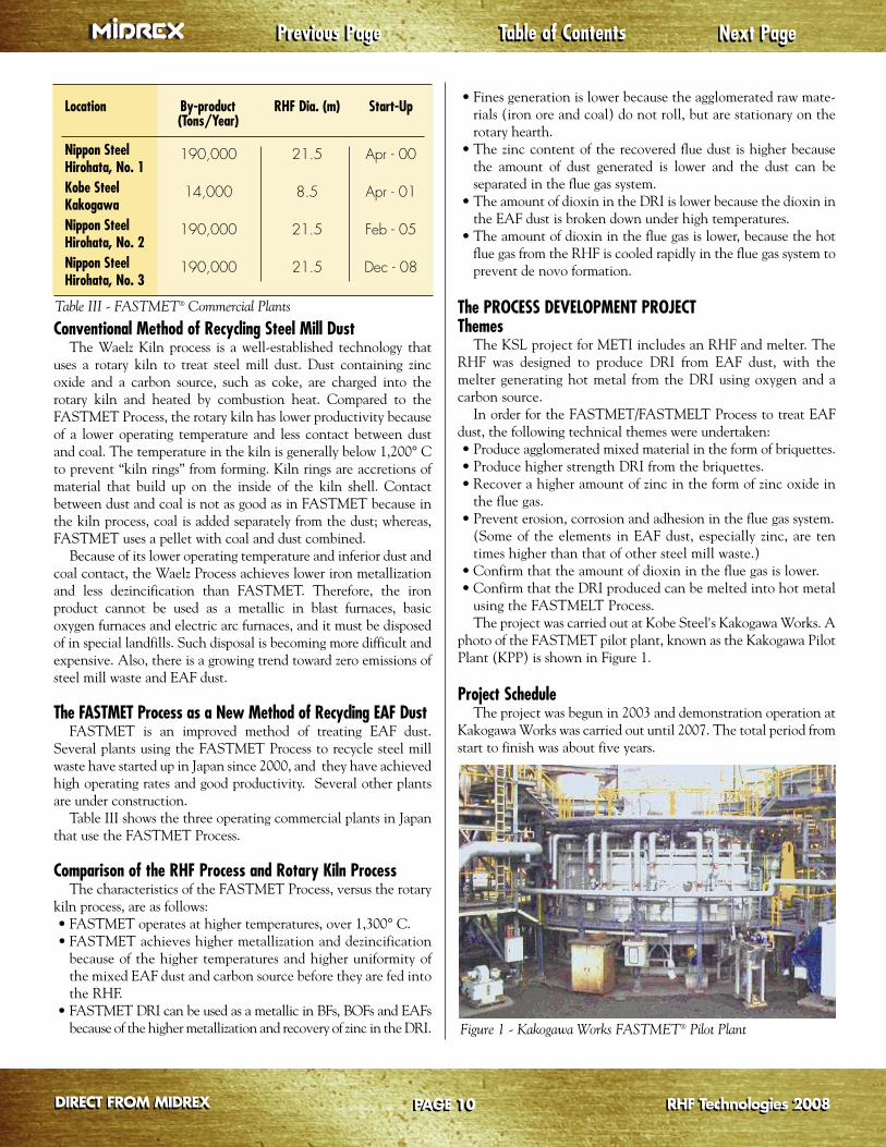
• Confirm that the amount of dioxin in the flue gas is lower.• Confirm that the DRI produced can be melted into hot metalusing the FASTMELT Process.The project was carried out at Kobe Steel's Kakogawa Works. A
photo of the FASTMET pilot plant, known as the Kakogawa PilotPlant (KPP) is shown in Figure 1.
Project ScheduleThe project was begun in 2003 and demonstration operation at
Kakogawa Works was carried out until 2007. The total period fromstart to finish was about five years.
Table of ContentsTable of Contents Next PageNext PagePrevious PagePrevious Page
PAGE 10PAGE 10DIRECT FROM MIDREXDIRECT FROM MIDREX
Figure 1 - Kakogawa Works FASTMET® Pilot Plant
RHF Technologies 2008RHF Technologies 2008
Location By-product RHF Dia. (m) Start-Up(Tons/Year)
Nippon Steel 190,000 21.5 Apr - 00Hirohata, No. 1Kobe Steel 14,000 8.5 Apr - 01KakogawaNippon Steel 190,000 21.5 Feb - 05Hirohata, No. 2Nippon Steel 190,000 21.5 Dec - 08Hirohata, No. 3
Table III - FASTMET® Commercial Plants

PILOT PLANT TESTS USING EAF DUSTProcess Flowsheet and EquipmentFigure 2 shows the process flowsheet for the FASTMET pilot
plant and Table IV provides details of the feedstock and equip-ment. The Rotary Hearth Furnace has the capacity to processapproximately 20,000 tons of dust per year. EAF dust, pulverized coal for the reductant and a binder are
mixed together. Then the mixture is agglomerated into cold briquettes (CBQ). The CBQ, fed into the RHF, are heated rapidly to temperatures of 1,200° C -1,400° C. The iron oxide inthe CBQ is reduced to metallic iron. Zinc, lead and other volatilesubstances are vaporized and reoxidized in the flue gas.The product DRI goes into the DRI container and is cooled
with nitrogen. The vaporized substances in the flue gas are collected in a bag filter and the zinc is recovered as zinc oxide. Thesensible heat of the flue gas is recovered by combustion air using aheat exchanger.
Characteristics of EAF Dust and CoalThe chemical compositions of the EAF dust and coal used in the
project are shown in Table V. EAF dust was classified into two groups.Group I contained higher total iron (Total Fe) and lower zinc.
Table of ContentsTable of Contents Next PageNext PagePrevious PagePrevious Page
PAGE 11PAGE 11DIRECT FROM MIDREXDIRECT FROM MIDREX
Coal
EAF Dust
Day Bins
Mixer
CBQ
Combustion AirAir
Preheater
OffgasCooler
Bag Filter
Burners
DRI ContainerDRI
ID Fan
Stack
Pulverizer
BriquetteMachine
Rotary Hearth Furnace
Figure 2 - Kakogawa Pilot Plant Flowsheet
Table IV - Feedstock and Equipment Details
Table V - Chemical Compositions of EAF Dust and Coal
RHF Technologies 2008RHF Technologies 2008
Item Description
Feedstock Iron ore, EAF Dust Bituminous, Non-coking Coal
RHF 11.5 meter OD Capacity: 20,000 t/y Feed Offgas Temperature: max. 1,400° C
EAF Dust
Total Fe Zn Pb C CaO SiO2 S Cl
Group 1 31~33 17~19 1 3 3~4 4~8 0.4 1~4Group 2 21~25 26~29 1~3 3~6 2~4 3~5 0.4~0.6 5~7
Coal
C H N O S
83.4 4.1 2.1 0.9 0.3

Test ResultsTable VI shows the mass balance for the project. The amount
of EAF dust treated was 263 tons, which produced 145 tons of DRI
and 79 tons of crude zinc oxide. The remaining output was vaporand other constituents.
Figure 3 shows the material flow and photos of the raw materi-als, cold briquettes and DRI.Table VII shows the chemical composition of the DRI and the
baghouse dust under the test conditions. The DRI metallizationaveraged 73 to 88 percent. The residual zinc content in the DRI was 1-4 percent, giving a
dezincification degree of 91-98 percent. The baghouse dust had57-70 percent zinc as zinc oxide, with less than one percent iron.The dezincification degree is calculated using the following formula:
De-zinc (%) = {1 – (ZnO in DRI / T.Fe in DRI) / (ZnO in dry ball / T.Fe in dry ball)} x 100
Most of the zinc in the EAF dust was vaporized and then re-oxi-dized in the flue gas.
Table of ContentsTable of Contents Next PageNext PagePrevious PagePrevious Page
PAGE 12PAGE 12DIRECT FROM MIDREXDIRECT FROM MIDREX
Table VI - Mass Balance of RHF Using EAF Dust
DRI
EAF Dust
Coal, etc.
ColdBriquette
in RHF
Vapor in flue
Zinc as Zinc Oxide
DRI
EAFDust
Coal
ColdBriquette
Figure 3 - Material Flow and Photos
RHF Technologies 2008RHF Technologies 2008
INEAF Dust 263 t Coal and other 63 t
Total 326 t
OUT
DRI 144 t Zinc oxide 79 t Gas and other 103 t
Total 326 t
Table VII - Chemical Composition of DRI and Baghouse Dust
DRI and Baghouse Dust
(Mass %) Total Fe Metallic Fe Zn Pb C CaO SiO2 S
Group I 46 – 53 40 – 46 0.7 – 2.4 0.1 5 – 11 5 – 8 9 – 13 0.6
DRI Group II 42 – 50 35 – 41 1 – 4 0.1 – 0.6 3 – 15 6 – 12 8 – 14 0.6 – 1.0
Average Met (%) 73 – 88 De-Zn Degree (%) 91 – 98 De-Pb Ratio (%) 87 – 97
(Mass %) Total Fe Zn Pb C CaO SiO2 S Cl
Crude Group I 0 – 0.2 64 – 70 3 – 4 0 – 0.1 0.1 – 0.2 0.1 – 0.2 0.4 5 – 8ZincOxide Group II 0 – 0.7 57 – 62 4 – 6 0 – 0.1 0.1 – 0.8 0.1 – 0.2 0.2 – 0.5 9 – 16

Figure 4 shows the relationshipbetween the temperature in the RHF anddezincification degree. As the tempera-ture in the RHF increases, the dezincifi-cation degree also rises. In addition, thedezincification degree increases withlonger retention time.Table VIII shows the emissions data of
the RHF at KPP. Samples were taken atthe outlet point of the bag filter. TheNOx content in the flue gas was controlled to less than 40 ppm (12 percent O2) and the dioxin content waslower than 0.1 ng-TEQ/Nm3.
DEVELOPMENT OF THE COAL-BASED FASTMELT PROCESSDevelopment Features of FASTMELTKSL and Midrex Technologies, Inc.
offer the FASTMELT process, using anElectric Ironmaking Furnace (EIF) tomelt hot DRI and produce hot metal.Figure 5 shows the features considered inthe development of the coal-basedmelter, which is a cylindrical stationaryfurnace operating at low pressure. Theultimate goal is continuous operation ofthe coal-based melter.
Table of ContentsTable of Contents Next PageNext PagePrevious PagePrevious Page
PAGE 13PAGE 13DIRECT FROM MIDREXDIRECT FROM MIDREX
70
75
80
85
90
95
100
1240 1280 1320 1360 1400Temperature of RHF
Dezin
cifica
tion
Degr
ee (%
)
Retention Time (1): Longer Retention Time (2): Shorter
Figure 4 - Relationship of Temperature of RHF and Dezincification
Table VIII - Emissions Data of RHF at KPP
DRI/HBICoal, etc.
Oxygen
(1) Suitable method of oxygen blowing, such as lance height
(4) Method of melting DRI,especially DRI chargingspeed depending on variousbrands of DRI
(2) Suitable method of addingcarbon into the hot metal
(3) Method of discharging slag from the stationary furnace under normal pressure
Continuous Operation
Coal
DRIMetal
N2
froun
N2
ygenOxy
2) Srb
3) M
f
(2ca
(3
Figure 5 - Coal-based Melter Features
RHF Technologies 2008RHF Technologies 2008
NOx (ppm) SOx (ppm) Dust (g/Nm3) Dioxin (ng-TEQ/Nm3)
<40 <50 <0.015 <0.1

Feed Material Metallization Total Fe Metallic Fe C
Iron Ore 86.0 77.3 66.5 7.9
EAF Dust Carbon Steel 82.4 58.1 47.0 7.2
EAF Dust Stainless Steel 73.2 35.4 25.3 3.1
Process Flowsheet and FacilityFigure 6 shows the process flow and Table IX
provides details of the equipment for the coal-basedmelter. DRI, coal and other materials are chargedinto the melting furnace from the top by gravity.Oxygen is blown into the furnace from the top usinglances, and input energy is obtained from the oxida-tion of carbon. The flue gas passes through a coolingchamber that cools the flue gas down to less than500° C using atomized water. This is followed by awet scrubber to remove dust. The flue gas then goesto an induced draft fan and then to a flare stack.Combustibles in the flue gas are completely burnedbefore discharge to the atmosphere. The capacity ofthe facility is 16,000 tons of hot metal per year.
Test ResultsA typical chemical composition of the DRI pro-
duced using various feed material is shown in Table X.Figures 7 and 8 show typical operations data during
Table of ContentsTable of ContentsPrevious PagePrevious Page
PAGE 14PAGE 14
Next PageNext Page
DIRECT FROM MIDREXDIRECT FROM MIDREX
Material Bins(DRI, Coal, Lime, etc.)
CoolingChamber Flare Stack
CombustionAir
ID-FanScrubber
Oxygen
Melter
ID-F-F-Fan
Melter
Ch
amber
Figure 6 - Process Flowsheet of the Coal-based Melter
1,350
1,450
1,550
1,650
3.5
4.0
4.5
5.0
5.5
6.0
[C]
temperature
2nd Blowing 3rd Blowing
2nd Tapping 3rd TappingTem
pera
ture
of H
ot M
etal
(°C)
Carb
on in
Met
al (%
)
13:46 14:00 14:15 14:29 14:44 14:58 15:12 15:27 15:41 15:56
Figure 7 - Transition of Metal Temperature and Carbon Content
Table IX - Profile of Coal-based Melter Table X - Typical Chemical Composition of DRI (mass %)
RHF Technologies 2008RHF Technologies 2008
Cylindrical Stationary Furnace Method
Tapping: Drilling
Dimension: I.D. 2m x 2.6m
Capacity: 16,000 t/y Hot Metal

the testwork. The DRI charging rate was adjustedto control the temperature of the hot metal. Thecarbon content in the hot metal was kept above4.7 percent.
Technical factors affecting the melting processwere investigated during the numerous test runs.
The following results were achieved: develop-ment of suitable methods of oxygen blowing andlance height, adding coal, smooth tapping of hotmetal iron using the coal-based melter.
FASTMELT PlantThe complete process flowsheet for a FASTMELT
Plant is shown in Figure 9. DRI is produced in theRHF and fed hot to the melter to make hot metal.
CONCLUSIONTrials conducted at the Kobe Steel Kakogawa
Pilot Plant with the support of METI provided thefollowing results for the FASTMELT Process treating EAF dust and iron oxide:• Development of an agglomerating technology tomix EAF dust and coal.
• Development of technology to achieve dezinci-fication of over 95 percent, higher metallizationand higher strength DRI than the rotary kilnprocess. As a result, the DRI can be used as ametallic feedstock for steelmaking, rather thanbeing disposed of.
• RHF operations using EAF dust were undertak-en without plugging, erosion and corrosionproblems in the flue gas system. This is a chal-lenge because EAF dust often contains ten timesthe amount of zinc as ordinary steel mill waste.
• Baghouse dust from the flue gas contained ahigher zinc content than the rotary kiln productand less than one percent iron.
• NOx, SOx and dioxin emission levels werelower than for the kiln process. Dioxin emis-sions were less than 0.1 ng-TEQ/Nm3.
• The FASTMELT process produced hot metalfrom iron ore fines and coal.
• The basic characteristics for melting varioustypes of DRI using oxygen and carbon were confirmed.
• Discharging slag from the stationary furnaceunder normal pressure was carried out smoothly.
• The cycle of DRI melting to produce hot metal and tappingwere repeated successfully.The coal-based FASTMET Process provides a viable method to
recover valuable metals using a rotary hearth furnace. Based onthe results gained from the pilot plant, we were able to developboth the basic concept and engineering for the FASTMETProcess. Taking an extra step using the FASTMELT Process, wesuccessfully produced hot metal from the DRI. Based on these
results, Kobe Steel is promoting commercial plants using theFASTMET Process to make DRI and the FASTMELT Process tomake hot metal.
When EAF dust is used as the raw material, both processes canbe used not only to recycle EAF dust, but also to effectively collectdifficult-to-recover zinc, which can be subsequently recovered. Inthis way, these two innovative direct reduction processes canreduce the burden on the environment and contribute to thedevelopment of a sustainable society.
DIRECT FROM MIDREXDIRECT FROM MIDREX
Table of ContentsTable of Contents Last PageLast PagePrevious PagePrevious Page
Iron OreCoal
Pellets/Briquettes
RecycledGas
Offgas
Coal,etc.
O2HotDRI
RHF
Coal-based MelterN2
Figure 9 - FASTMELT Plant Flowsheet
0
500
1000
1500
2000
DRI Charging Rate
2nd Tapping
2nd Blowing 3rd Blowing
Coal Charging Rate
3rd Tapping
DRI &
Coa
l Cha
rging
Rat
es (k
g/h)
Figure 8 - Transition of DRI and Coal Charging Rates
RHF Technologies 2008RHF Technologies 2008PAGE 15PAGE 15