special specifications that can be specified by the ... · 3 the optimal table specification can...
TRANSCRIPT

TU
Ⅱ̶29 Ⅱ̶30
TU
TU
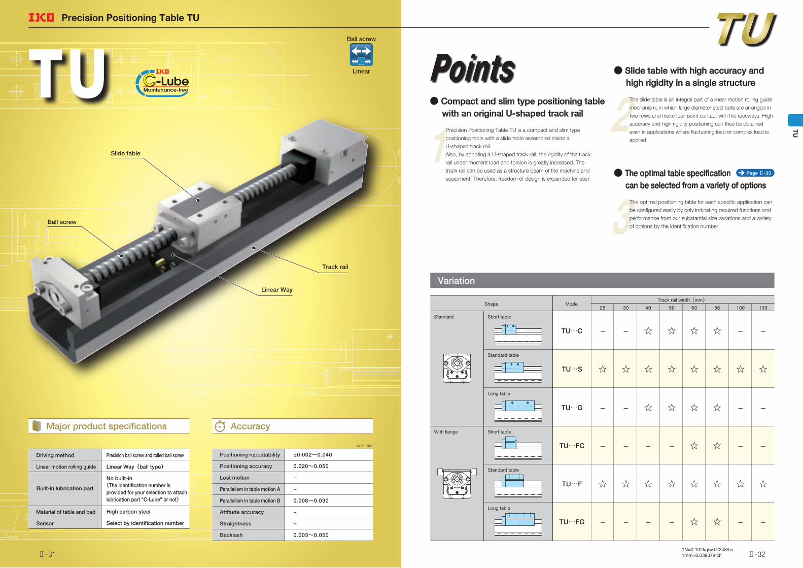
Driving method
Linear motion rolling guide
Material of table and bed
Sensor
Positioning repeatability
Positioning accuracy
Lost motion
Parallelism in table motion A
Parallelism in table motion B
Attitude accuracy
Straightness
Backlash
±0.002~0.040
0.020~0.050
−
−
0.008~0.030
−
−
0.003~0.050
Precision ball screw and rolled ball screw
Linear Way(ball type)
No built-in(The identification number is provided for your selection to attach lubrication part "C-Lube" or not)
High carbon steel
Select by identification number
Precision Positioning Table TU
Track rail
Linear Way
Slide table
Ball screw
Points
1● Compact and slim type positioning table with an original U-shaped track rail
Precision Positioning Table TU is a compact and slim type
positioning table with a slide table assembled inside a
U-shaped track rail.
Also, by adopting a U-shaped track rail, the rigidity of the track
rail under moment load and torsion is greatly increased. The
track rail can be used as a structure beam of the machine and
equipment. Therefore, freedom of design is expanded for user.
2● Slide table with high accuracy and high rigidity in a single structure
The slide table is an integral part of a linear motion rolling guide
mechanism, in which large diameter steel balls are arranged in
two rows and make four-point contact with the raceways. High
accuracy and high rigidity positioning can thus be obtained
even in applications where fluctuating load or complex load is
applied.
3● The optimal table specification can be selected from a variety of options
The optimal positioning table for each specific application can
be configured easily by only indicating required functions and
performance from our substantial size variations and a variety
of options by the identification number.
Variation
Shape ModelTrack rail width(mm)
With flange
Standard
TU…S
TU…G
TU…FC
TU…F
TU…C
TU…FG
Short table
Standard table
Long table
Short table
Standard table
Long table
25 1301008660504030
−
☆☆
☆☆☆☆☆☆☆☆
☆☆☆☆
☆☆☆☆
☆☆☆☆☆☆☆☆
☆☆ −−−−−−
−−−−−−
−−−−
−−−
unit: mm
Major product specifications Accuracy
Built-in lubrication part
Page Ⅱ-33
Ball screw
Linear
Ⅱ̶31 Ⅱ̶32
TU
1N=0.102kgf=0.2248lbs.1mm=0.03937inch
Precision Positioning Table TU
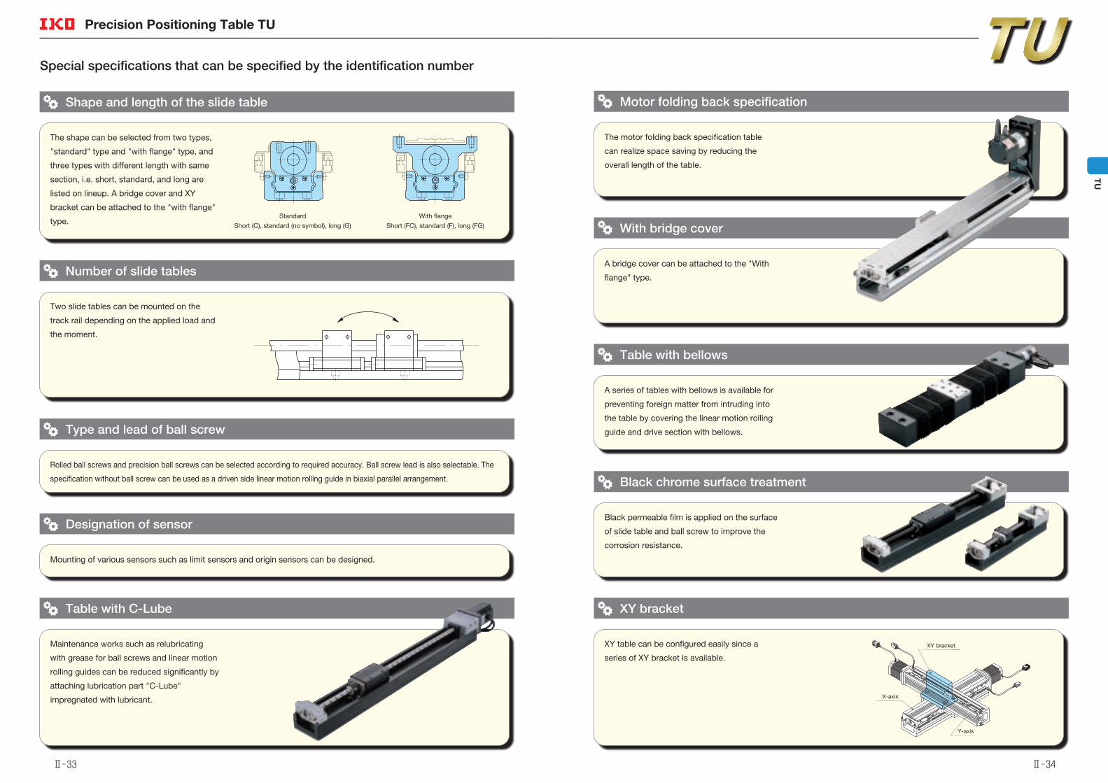
The shape can be selected from two types,
"standard" type and "with flange" type, and
three types with different length with same
section, i.e. short, standard, and long are
listed on lineup. A bridge cover and XY
bracket can be attached to the "with flange"
type.Standard With flange
Short (C), standard (no symbol), long (G) Short (FC), standard (F), long (FG)
Special specifications that can be specified by the identification number
Shape and length of the slide table
Maintenance works such as relubricating
with grease for ball screws and linear motion
rolling guides can be reduced significantly by
attaching lubrication part "C-Lube"
impregnated with lubricant.
Table with C-Lube
XY table can be configured easily since a
series of XY bracket is available.
XY bracket
Black permeable film is applied on the surface
of slide table and ball screw to improve the
corrosion resistance.
Black chrome surface treatment
A series of tables with bellows is available for
preventing foreign matter from intruding into
the table by covering the linear motion rolling
guide and drive section with bellows.
Table with bellows
The motor folding back specification table
can realize space saving by reducing the
overall length of the table.
Motor folding back specification
A bridge cover can be attached to the "With
flange" type.
With bridge cover
Two slide tables can be mounted on the
track rail depending on the applied load and
the moment.
Number of slide tables
Rolled ball screws and precision ball screws can be selected according to required accuracy. Ball screw lead is also selectable. The
specification without ball screw can be used as a driven side linear motion rolling guide in biaxial parallel arrangement.
Type and lead of ball screw
Mounting of various sensors such as limit sensors and origin sensors can be designed.
Designation of sensor
XY bracket
X-axis
Y-axis
Ⅱ̶33 Ⅱ̶34
TU
1N=0.102kgf=0.2248lbs.1mm=0.03937inch
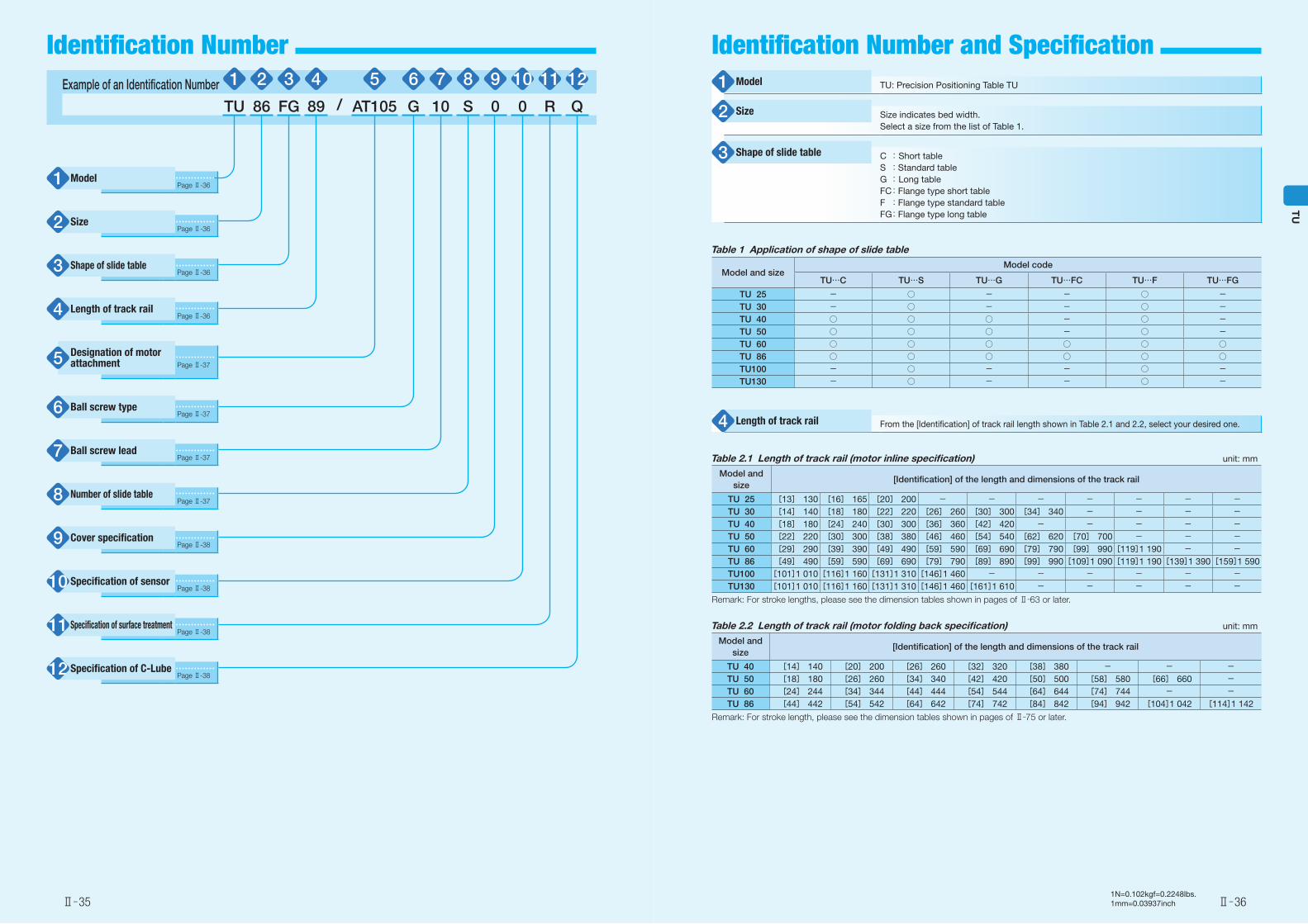
Example of an Identification Number 1 2 3 4 5 6 7 8 9 10 11 12
TU 86 FG 89 / AT105 G 10 S 0 0 R Q
Page Ⅱ-36
Page Ⅱ-36
Page Ⅱ-36
Page Ⅱ-36
Page Ⅱ-37
Page Ⅱ-37
Page Ⅱ-37
Page Ⅱ-37
Page Ⅱ-38
Page Ⅱ-38
Page Ⅱ-38
Page Ⅱ-38
TU: Precision Positioning Table TU
Size indicates bed width.Select a size from the list of Table 1.
C : Short tableS :Standard tableG : Long tableFC :Flange type short tableF :Flange type standard tableFG :Flange type long table
Table 1 Application of shape of slide table
Model and sizeModel code
TU…C TU…S TU…G TU…FC TU…F TU…FG
TU 25 - ○ - - ○ -TU 30 - ○ - - ○ -TU 40 ○ ○ ○ - ○ -TU 50 ○ ○ ○ - ○ -TU 60 ○ ○ ○ ○ ○ ○TU 86 ○ ○ ○ ○ ○ ○TU100 - ○ - - ○ -TU130 - ○ - - ○ -
From the [Identification] of track rail length shown in Table 2.1 and 2.2, select your desired one.
Table 2.1 Length of track rail (motor inline specification) unit: mm
Model and size
[Identification] of the length and dimensions of the track rail
TU 25 [13] 130 [16] 165 [20] 200 - - - - - - -TU 30 [14] 140 [18] 180 [22] 220 [26] 260 [30] 300 [34] 340 - - - -TU 40 [18] 180 [24] 240 [30] 300 [36] 360 [42] 420 - - - - -TU 50 [22] 220 [30] 300 [38] 380 [46] 460 [54] 540 [62] 620 [70] 700 - - -TU 60 [29] 290 [39] 390 [49] 490 [59] 590 [69] 690 [79] 790 [99] 990[119]1 190 - -TU 86 [49] 490 [59] 590 [69] 690 [79] 790 [89] 890 [99] 990[109]1 090[119]1 190[139]1 390[159]1 590TU100 [101]1 010[116]1 160[131]1 310[146]1 460 - - - - - -TU130 [101]1 010[116]1 160[131]1 310[146]1 460[161]1 610 - - - - -
Remark: For stroke lengths, please see the dimension tables shown in pages of Ⅱ̶63 or later.
Table 2.2 Length of track rail (motor folding back specification) unit: mm
Model and size
[Identification] of the length and dimensions of the track rail
TU 40 [14] 140 [20] 200 [26] 260 [32] 320 [38] 380 - - -TU 50 [18] 180 [26] 260 [34] 340 [42] 420 [50] 500 [58] 580 [66] 660 -TU 60 [24] 244 [34] 344 [44] 444 [54] 544 [64] 644 [74] 744 - -TU 86 [44] 442 [54] 542 [64] 642 [74] 742 [84] 842 [94] 942 [104]1 042 [114]1 142
Remark: For stroke length, please see the dimension tables shown in pages of Ⅱ̶75 or later.
Model1
Size2
Shape of slide table3
Length of track rail4
Designation of motor attachment 5
Ball screw type6
Ball screw lead7
Number of slide table8
Cover specification9
Specification of C-Lube 12
Specification of surface treatment11
Specification of sensor 10
Model1
Size2
Shape of slide table3
Length of track rail4
Ⅱ̶35 Ⅱ̶36
TU
Identification Number and Specification Identification Number
1N=0.102kgf=0.2248lbs.1mm=0.03937inch
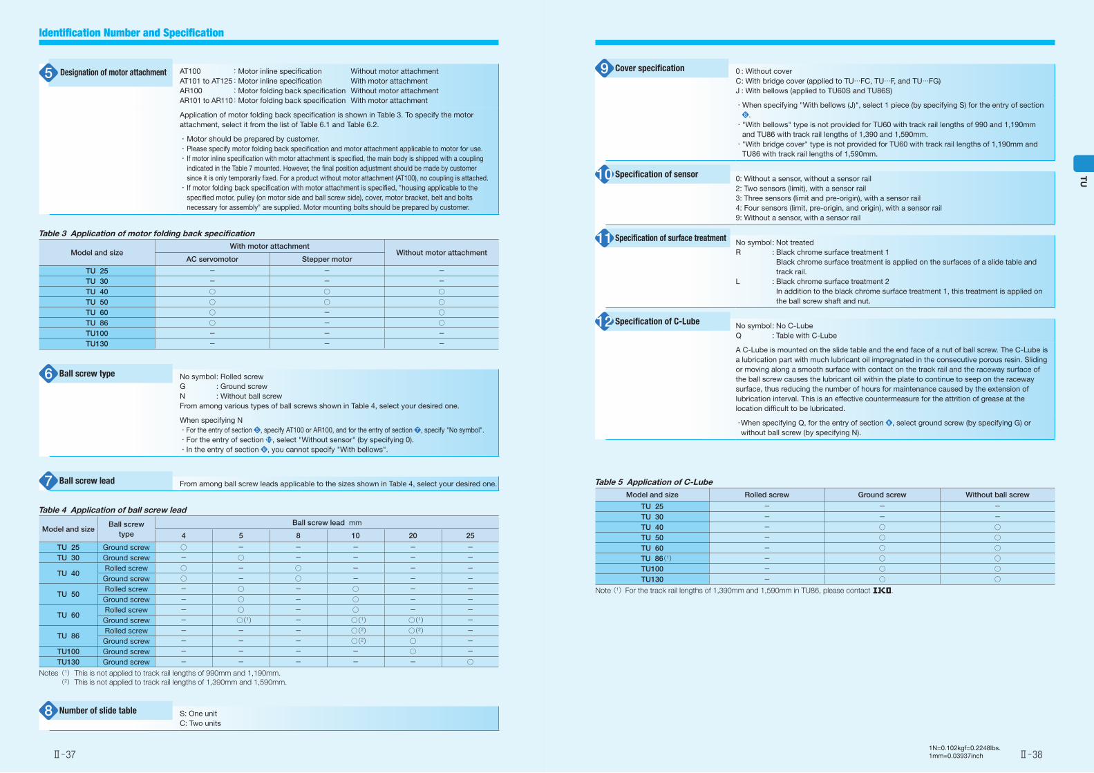
0 : Without coverC : With bridge cover (applied to TU…FC, TU…F, and TU…FG)J : With bellows (applied to TU60S and TU86S)
・ When specifying "With bellows (J)", select 1 piece (by specifying S) for the entry of section 8 .
・ "With bellows" type is not provided for TU60 with track rail lengths of 990 and 1,190mm and TU86 with track rail lengths of 1,390 and 1,590mm.・ "With bridge cover" type is not provided for TU60 with track rail lengths of 1,190mm and
TU86 with track rail lengths of 1,590mm.
0: Without a sensor, without a sensor rail2: Two sensors (limit), with a sensor rail3: Three sensors (limit and pre-origin), with a sensor rail4: Four sensors (limit, pre-origin, and origin), with a sensor rail9: Without a sensor, with a sensor rail
No symbol : Not treatedR : Black chrome surface treatment 1 Black chrome surface treatment is applied on the surfaces of a slide table and
track rail.L : Black chrome surface treatment 2 In addition to the black chrome surface treatment 1, this treatment is applied on
the ball screw shaft and nut.
No symbol : No C-LubeQ : Table with C-Lube
A C-Lube is mounted on the slide table and the end face of a nut of ball screw. The C-Lube is a lubrication part with much lubricant oil impregnated in the consecutive porous resin. Sliding or moving along a smooth surface with contact on the track rail and the raceway surface of the ball screw causes the lubricant oil within the plate to continue to seep on the raceway surface, thus reducing the number of hours for maintenance caused by the extension of lubrication interval. This is an effective countermeasure for the attrition of grease at the location difficult to be lubricated.
・ When specifying Q, for the entry of section 6 , select ground screw (by specifying G) or without ball screw (by specifying N).
Table 3 Application of motor folding back specification
Model and sizeWith motor attachment
Without motor attachmentAC servomotor Stepper motor
TU 25 - - -TU 30 - - -TU 40 ○ ○ ○TU 50 ○ ○ ○TU 60 ○ - ○TU 86 ○ - ○TU100 - - -TU130 - - -
AT100 :Motor inline specification Without motor attachmentAT101 to AT125 :Motor inline specification With motor attachmentAR100 :Motor folding back specification Without motor attachmentAR101 to AR110 :Motor folding back specification With motor attachment
Application of motor folding back specification is shown in Table 3. To specify the motor attachment, select it from the list of Table 6.1 and Table 6.2.
・ Motor should be prepared by customer.・ Please specify motor folding back specification and motor attachment applicable to motor for use.・ If motor inline specification with motor attachment is specified, the main body is shipped with a coupling
indicated in the Table 7 mounted. However, the final position adjustment should be made by customer since it is only temporarily fixed. For a product without motor attachment (AT100), no coupling is attached.
・ If motor folding back specification with motor attachment is specified, "housing applicable to the specified motor, pulley (on motor side and ball screw side), cover, motor bracket, belt and bolts necessary for assembly" are supplied. Motor mounting bolts should be prepared by customer.
Table 4 Application of ball screw lead
Model and sizeBall screw
type
Ball screw lead mm
4 5 8 10 20 25
TU 25 Ground screw ○ - - - - -TU 30 Ground screw - ○ - - - -
TU 40Rolled screw ○ - ○ - - -Ground screw ○ - ○ - - -
TU 50Rolled screw - ○ - ○ - -Ground screw - ○ - ○ - -
TU 60Rolled screw - ○ - ○ - -Ground screw - ○(1) - ○(1) ○(1) -
TU 86Rolled screw - - - ○(2) ○(2) -Ground screw - - - ○(2) ○ -
TU100 Ground screw - - - - ○ -TU130 Ground screw - - - - - ○
Notes (1) This is not applied to track rail lengths of 990mm and 1,190mm. (2) This is not applied to track rail lengths of 1,390mm and 1,590mm.
From among ball screw leads applicable to the sizes shown in Table 4, select your desired one.
S: One unitC: Two units
No symbol : Rolled screwG : Ground screwN : Without ball screwFrom among various types of ball screws shown in Table 4, select your desired one.
When specifying N・For the entry of section 5 , specify AT100 or AR100, and for the entry of section 7 , specify "No symbol".・For the entry of section 10, select "Without sensor" (by specifying 0).・In the entry of section 9 , you cannot specify "With bellows".
Table 5 Application of C-LubeModel and size Rolled screw Ground screw Without ball screw
TU 25 - - -TU 30 - - -TU 40 - ○ ○TU 50 - ○ ○TU 60 - ○ ○
TU 86(1) - ○ ○TU100 - ○ ○TU130 - ○ ○
Note (1)For the track rail lengths of 1,390mm and 1,590mm in TU86, please contact .
Designation of motor attachment 5
Ball screw type6
Ball screw lead7
Number of slide table8
Cover specification9
Specification of sensor 10
Specification of surface treatment11
Specification of C-Lube 12
Ⅱ̶37 Ⅱ̶38
TU
Identification Number and Specification
1N=0.102kgf=0.2248lbs.1mm=0.03937inch
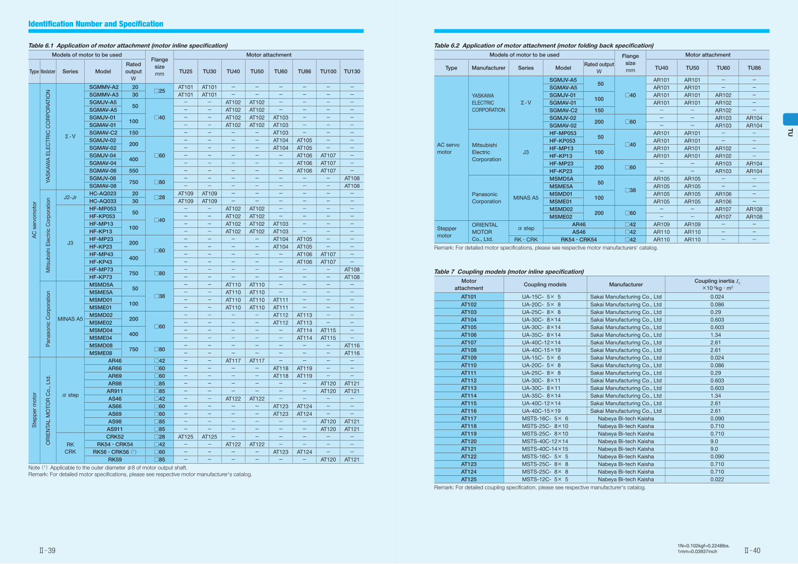
Table 6.1 Application of motor attachment (motor inline specification)Models of motor to be used
Flange sizemm
Motor attachment
Type Manufacturer Series ModelRated output
WTU25 TU30 TU40 TU50 TU60 TU86 TU100 TU130
AC
ser
vom
otor
YAS
KA
WA
ELE
CTR
IC C
OR
PO
RAT
ION
Σ-Ⅴ
SGMMV-A2 20□25
AT101 AT101 - - - - - -SGMMV-A3 30 AT101 AT101 - - - - - -SGMJV-A5
50
□40
- - AT102 AT102 - - - -SGMAV-A5 - - AT102 AT102 - - - -SGMJV-01
100- - AT102 AT102 AT103 - - -
SGMAV-01 - - AT102 AT102 AT103 - - -SGMAV-C2 150 - - - - AT103 - - -SGMJV-02
200
□60
- - - - AT104 AT105 - -SGMAV-02 - - - - AT104 AT105 - -SGMJV-04
400- - - - - AT106 AT107 -
SGMAV-04 - - - - - AT106 AT107 -SGMAV-06 550 - - - - - AT106 AT107 -SGMJV-08
750 □80- - - - - - - AT108
SGMAV-08 - - - - - - - AT108
Mits
ubis
hi E
lect
ric C
orp
orat
ion J2-Jr
HC-AQ023 20□28
AT109 AT109 - - - - - -HC-AQ033 30 AT109 AT109 - - - - - -
J3
HF-MP05350
□40
- - AT102 AT102 - - - -HF-KP053 - - AT102 AT102 - - - -HF-MP13
100- - AT102 AT102 AT103 - - -
HF-KP13 - - AT102 AT102 AT103 - - -HF-MP23
200□60
- - - - AT104 AT105 - -HF-KP23 - - - - AT104 AT105 - -HF-MP43
400- - - - - AT106 AT107 -
HF-KP43 - - - - - AT106 AT107 -HF-MP73
750 □80- - - - - - - AT108
HF-KP73 - - - - - - - AT108
Pan
ason
ic C
orp
orat
ion
MINAS A5
MSMD5A50
□38
- - AT110 AT110 - - - -MSME5A - - AT110 AT110 - - - -MSMD01
100- - AT110 AT110 AT111 - - -
MSME01 - - AT110 AT110 AT111 - - -MSMD02
200□60
- - - - AT112 AT113 - -MSME02 - - - - AT112 AT113 - -MSMD04
400- - - - - AT114 AT115 -
MSME04 - - - - - AT114 AT115 -MSMD08
750 □80- - - - - - - AT116
MSME08 - - - - - - - AT116
Ste
pp
er m
otor
OR
IEN
TAL
MO
TOR
Co.
, Ltd
.
α step
AR46 □42 - - AT117 AT117 - - - -AR66 □60 - - - - AT118 AT119 - -AR69 □60 - - - - AT118 AT119 - -AR98 □85 - - - - - - AT120 AT121AR911 □85 - - - - - - AT120 AT121AS46 □42 - - AT122 AT122 - - - -AS66 □60 - - - - AT123 AT124 - -AS69 □60 - - - - AT123 AT124 - -AS98 □85 - - - - - - AT120 AT121AS911 □85 - - - - - - AT120 AT121
RKCRK
CRK52 □28 AT125 AT125 - - - - - -RK54・CRK54 □42 - - AT122 AT122 - - - -
RK56・CRK56 (1) □60 - - - - AT123 AT124 - -RK59 □85 - - - - - - AT120 AT121
Note (1)Applicable to the outer diameter φ8 of motor output shaft.Remark: For detailed motor specifications, please see respective motor manufacturer's catalog.
Table 6.2 Application of motor attachment (motor folding back specification)Models of motor to be used Flange
sizemm
Motor attachment
Type Manufacturer Series ModelRated output
WTU40 TU50 TU60 TU86
AC servo motor
YASKAWA ELECTRIC CORPORATION
Σ-Ⅴ
SGMJV-A5 50
□40
AR101 AR101 - -SGMAV-A5 AR101 AR101 - -SGMJV-01
100AR101 AR101 AR102 -
SGMAV-01 AR101 AR101 AR102 -SGMAV-C2 150 - - AR102 -SGMJV-02
200 □60- - AR103 AR104
SGMAV-02 - - AR103 AR104
Mitsubishi Electric Corporation
J3
HF-MP053 50
□40
AR101 AR101 - -HF-KP053 AR101 AR101 - -HF-MP13
100AR101 AR101 AR102 -
HF-KP13 AR101 AR101 AR102 -HF-MP23
200 □60- - AR103 AR104
HF-KP23 - - AR103 AR104
Panasonic Corporation
MINAS A5
MSMD5A 50
□38
AR105 AR105 - -MSME5A AR105 AR105 - -MSMD01
100AR105 AR105 AR106 -
MSME01 AR105 AR105 AR106 -MSMD02
200 □60- - AR107 AR108
MSME02 - - AR107 AR108
Stepper motor
ORIENTAL MOTOR Co., Ltd.
α stepAR46 □42 AR109 AR109 - -AS46 □42 AR110 AR110 - -
RK・CRK RK54・CRK54 □42 AR110 AR110 - -Remark: For detailed motor specifications, please see respective motor manufacturers' catalog.
Table 7 Coupling models (motor inline specification)Motor
attachmentCoupling models Manufacturer
Coupling inertia JC
×10-5kg・m2
AT101 UA-15C- 5× 5 Sakai Manufacturing Co., Ltd 0.024AT102 UA-20C- 5× 8 Sakai Manufacturing Co., Ltd 0.086AT103 UA-25C- 8× 8 Sakai Manufacturing Co., Ltd 0.29AT104 UA-30C- 8×14 Sakai Manufacturing Co., Ltd 0.603AT105 UA-30C- 8×14 Sakai Manufacturing Co., Ltd 0.603AT106 UA-35C- 8×14 Sakai Manufacturing Co., Ltd 1.34AT107 UA-40C-12×14 Sakai Manufacturing Co., Ltd 2.61AT108 UA-40C-15×19 Sakai Manufacturing Co., Ltd 2.61AT109 UA-15C- 5× 6 Sakai Manufacturing Co., Ltd 0.024AT110 UA-20C- 5× 8 Sakai Manufacturing Co., Ltd 0.086AT111 UA-25C- 8× 8 Sakai Manufacturing Co., Ltd 0.29AT112 UA-30C- 8×11 Sakai Manufacturing Co., Ltd 0.603AT113 UA-30C- 8×11 Sakai Manufacturing Co., Ltd 0.603AT114 UA-35C- 8×14 Sakai Manufacturing Co., Ltd 1.34AT115 UA-40C-12×14 Sakai Manufacturing Co., Ltd 2.61AT116 UA-40C-15×19 Sakai Manufacturing Co., Ltd 2.61AT117 MSTS-16C- 5× 6 Nabeya Bi-tech Kaisha 0.090AT118 MSTS-25C- 8×10 Nabeya Bi-tech Kaisha 0.710AT119 MSTS-25C- 8×10 Nabeya Bi-tech Kaisha 0.710AT120 MSTS-40C-12×14 Nabeya Bi-tech Kaisha 9.0AT121 MSTS-40C-14×15 Nabeya Bi-tech Kaisha 9.0AT122 MSTS-16C- 5× 5 Nabeya Bi-tech Kaisha 0.090AT123 MSTS-25C- 8× 8 Nabeya Bi-tech Kaisha 0.710AT124 MSTS-25C- 8× 8 Nabeya Bi-tech Kaisha 0.710AT125 MSTS-12C- 5× 5 Nabeya Bi-tech Kaisha 0.022
Remark: For detailed coupling specification, please see respective manufacturer's catalog.
Ⅱ̶39 Ⅱ̶40
TU
Identification Number and Specification
1N=0.102kgf=0.2248lbs.1mm=0.03937inch
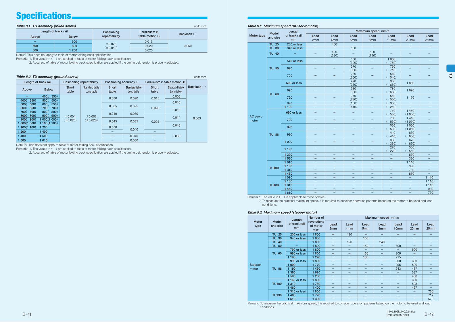
Table 8.2 TU accuracy (ground screw) unit: mm
Length of track rail Positioning repeatability Positioning accuracy (1) Parallelism in table motion B
Backlash (1)Above Below
Short table
Standard tableLong table
Short table
Standard tableLong table
Short table
Standard tableLong table
- 400( 350)
±0.004(±0.020)
±0.002(±0.020)
0.030 0.020 0.0150.008
0.003
400( 350) 500( 500)0.010
500( 500) 600( 550)0.035 0.025
0.020600( 550) 700( 700)0.012
700( 700) 800( 800)0.040 0.030
800( 800) 900( 900)
0.0250.014
900( 900) 1 000(1 000)0.045 0.035
1 000(1 000) 1 100(1 100)0.016
1 100(1 100) 1 200 0.0500.040
1 200 1 400 - -0.0301 400 1 500 - 0.045 -
1 500 1 610 - 0.050 -Note (1)This does not apply to table of motor folding back specification.Remarks 1. The values in ( ) are applied to table of motor folding back specification. 2. Accuracy of table of motor folding back specification are applied if the timing belt tension is properly adjusted.
Table 8.1 TU accuracy (rolled screw) unit: mm
Length of track rail Positioning repeatability
Parallelism in table motion B
Backlash (1)Above Below
- 500±0.025
(±0.040)
0.0150.050500 800 0.020
800 1 200 0.025
Note(1) This does not apply to table of motor folding back specification.Remarks 1. The values in ( ) are applied to table of motor folding back specification. 2. Accuracy of table of motor folding back specification are applied if the timing belt tension is properly adjusted.
Table 9.2 Maximum speed (stepper motor)
Motor type
Model and size
Length of track rail
mm
Number of revolutions
of motormin-1
Maximum speed mm/s
Lead2mm
Lead4mm
Lead5mm
Lead8mm
Lead10mm
Lead20mm
Lead25mm
Stepper motor
TU 25 200 or less 1 800 - 120 - - - - -TU 30 340 or less 1 800 - - 150 - - - -TU 40 - 1 800 - 120 - 240 - - -TU 50 - 1 800 - - 150 - 300 - -
TU 60 790 or less 1 800 - - - - - 600 - 990 or less 1 800 - - 150 - 300 - -1 190 1 290 - - 108 - 215 - -
TU 86
990 or less 1 800 - - - - 300 600 -1 090 1 770 - - - - 295 590 -1 190 1 460 - - - - 243 487 -1 390 1 610 - - - - - 537 -1 590 1 200 - - - - - 400 -
TU1001 160 or less 1 800 - - - - - 600 -1 310 1 780 - - - - - 593 -1 460 1 400 - - - - - 467 -
TU1301 310 or less 1 800 - - - - - - 7501 460 1 720 - - - - - - 7171 610 1 390 - - - - - - 579
Remark: To measure the practical maximum speed, it is required to consider operation patterns based on the motor to be used and load conditions.
Table 9.1 Maximum speed (AC servomotor)
Motor typeModel
and size
Length of track rail
mm
Maximum speed mm/s
Lead2mm
Lead4mm
Lead5mm
Lead8mm
Lead10mm
Lead20mm
Lead25mm
AC servo motor
TU 25 200 or less - 400 - - - - -TU 30 340 or less - - 500 - - - -
TU 40 - - 400(390) - 800
(790) - - -
TU 50
540 or less - - 500(390) - 1 000
( 780) - -
620 - - 370(350) - 750
( 710) - -
700 - - 280(260) - 560
( 540) - -
TU 60
590 or less - - 470(330) - 930
( 660) 1 860 -
690 - - 380(330) - 780
( 660) 1 620 -
790 - - 270(280) - 560
( 560) 1 170 -
990 - - (160) - ( 330) - -1 190 - - (110) - ( 210) - -
TU 86
690 or less - - - - 750( 530)
1 480(1 050) -
790 - - - - 700( 530)
1 410(1 050) -
890 - - - - 530( 530)
1 060(1 050) -
990 - - - - 410( 410)
830( 830) -
1 090 - - - - 330( 330)
670( 670) -
1 190 - - - - 270( 270)
550( 550) -
1 390 - - - - - 530 -1 590 - - - - - 390 -
TU100
1 010 - - - - - 1 110 -1 160 - - - - - 990 -1 310 - - - - - 730 -1 460 - - - - - 560 -
TU130
1 010 - - - - - - 1 1101 160 - - - - - - 1 1101 310 - - - - - - 1 1101 460 - - - - - - 9301 610 - - - - - - 730
Remark 1. The value in ( ) is applicable to rolled screws. 2. To measure the practical maximum speed, it is required to consider operation patterns based on the motor to be used and load
conditions.
Ⅱ̶41 Ⅱ̶42
TU
Specifications
1N=0.102kgf=0.2248lbs.1mm=0.03937inch
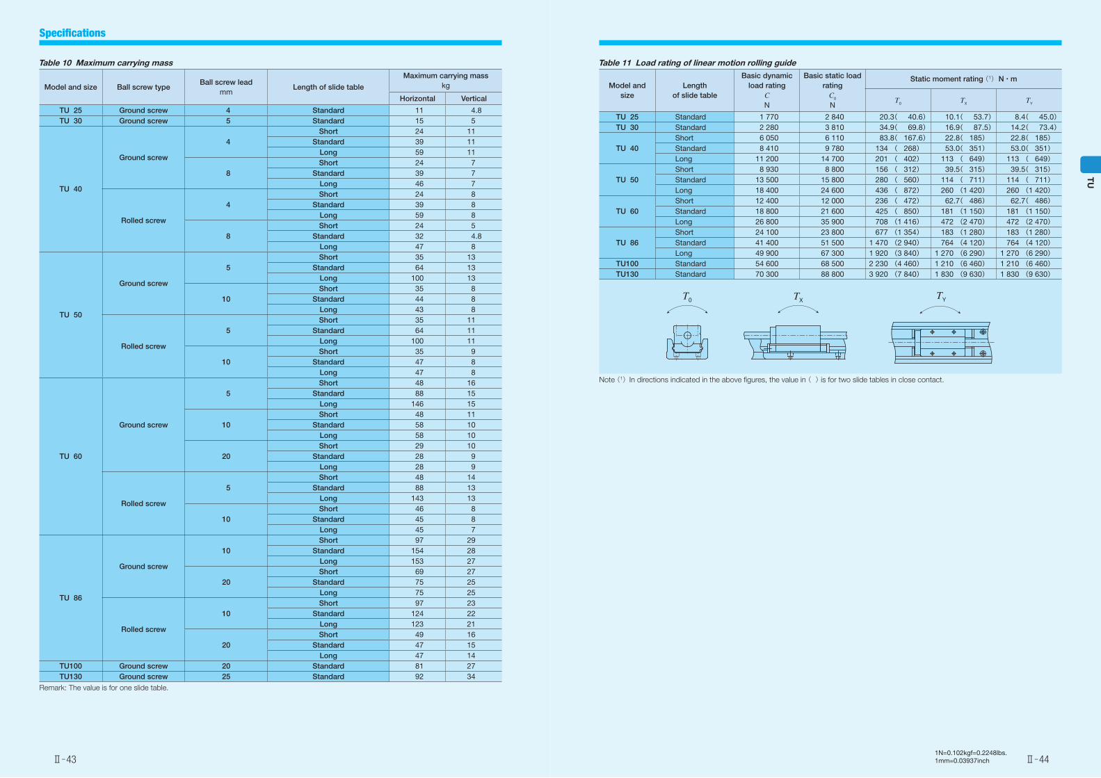
Table 10 Maximum carrying mass
Model and size Ball screw typeBall screw lead
mmLength of slide table
Maximum carrying masskg
Horizontal Vertical
TU 25 Ground screw 4 Standard 11 4.8TU 30 Ground screw 5 Standard 15 5
TU 40
Ground screw
4Short 24 11
Standard 39 11Long 59 11
8Short 24 7
Standard 39 7Long 46 7
Rolled screw
4Short 24 8
Standard 39 8Long 59 8
8Short 24 5
Standard 32 4.8Long 47 8
TU 50
Ground screw
5Short 35 13
Standard 64 13Long 100 13
10Short 35 8
Standard 44 8Long 43 8
Rolled screw
5Short 35 11
Standard 64 11Long 100 11
10Short 35 9
Standard 47 8Long 47 8
TU 60
Ground screw
5Short 48 16
Standard 88 15Long 146 15
10Short 48 11
Standard 58 10Long 58 10
20Short 29 10
Standard 28 9Long 28 9
Rolled screw
5Short 48 14
Standard 88 13Long 143 13
10Short 46 8
Standard 45 8Long 45 7
TU 86
Ground screw
10Short 97 29
Standard 154 28Long 153 27
20Short 69 27
Standard 75 25Long 75 25
Rolled screw
10Short 97 23
Standard 124 22Long 123 21
20Short 49 16
Standard 47 15Long 47 14
TU100 Ground screw 20 Standard 81 27TU130 Ground screw 25 Standard 92 34
Remark: The value is for one slide table.
Table 11 Load rating of linear motion rolling guide
Model and size
Length of slide table
Basic dynamic load rating
CN
Basic static load rating
C0
N
Static moment rating (1) N・m
T0 TX TY
TU 25 Standard 1 770 2 840 20.3( 40.6) 10.1( 53.7) 8.4( 45.0)TU 30 Standard 2 280 3 810 34.9( 69.8) 16.9( 87.5) 14.2( 73.4)
TU 40Short 6 050 6 110 83.8( 167.6) 22.8( 185) 22.8( 185)Standard 8 410 9 780 134 ( 268) 53.0( 351) 53.0( 351)Long 11 200 14 700 201 ( 402) 113 ( 649) 113 ( 649)
TU 50Short 8 930 8 800 156 ( 312) 39.5( 315) 39.5( 315)Standard 13 500 15 800 280 ( 560) 114 ( 711) 114 ( 711)Long 18 400 24 600 436 ( 872) 260 (1 420) 260 (1 420)
TU 60Short 12 400 12 000 236 ( 472) 62.7( 486) 62.7( 486)Standard 18 800 21 600 425 ( 850) 181 (1 150) 181 (1 150)Long 26 800 35 900 708 (1 416) 472 (2 470) 472 (2 470)
TU 86Short 24 100 23 800 677 (1 354) 183 (1 280) 183 (1 280)Standard 41 400 51 500 1 470 (2 940) 764 (4 120) 764 (4 120)Long 49 900 67 300 1 920 (3 840) 1 270 (6 290) 1 270 (6 290)
TU100 Standard 54 600 68 500 2 230 (4 460) 1 210 (6 460) 1 210 (6 460)TU130 Standard 70 300 88 800 3 920 (7 840) 1 830 (9 630) 1 830 (9 630)
Note (1)In directions indicated in the above figures, the value in ( ) is for two slide tables in close contact.
T0 TX TY
Ⅱ̶43 Ⅱ̶44
TU
Specifications
1N=0.102kgf=0.2248lbs.1mm=0.03937inch
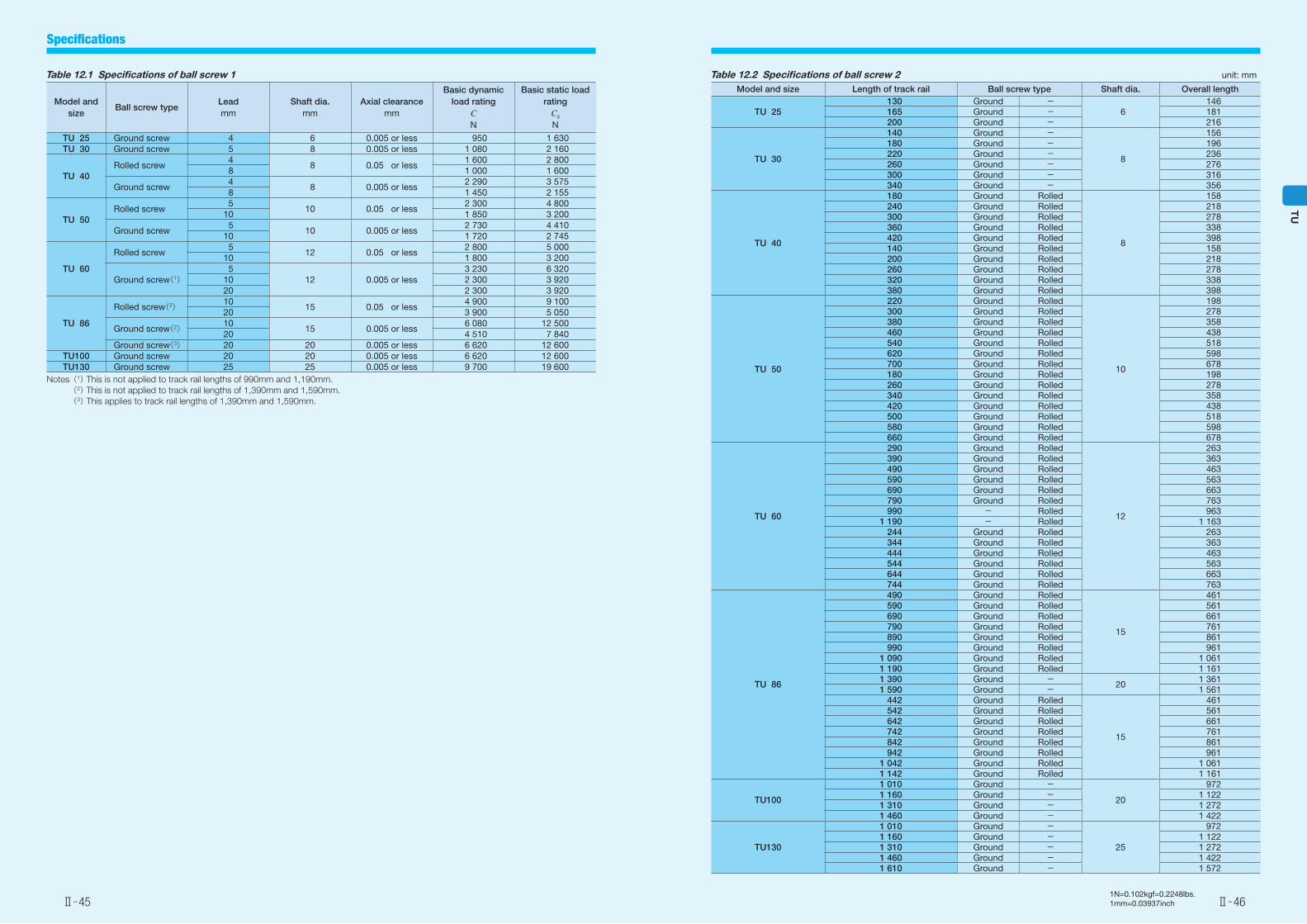
Table 12.1 Specifications of ball screw 1
Model and size
Ball screw typeLeadmm
Shaft dia.mm
Axial clearancemm
Basic dynamic load rating
CN
Basic static load rating
C0
N
TU 25 Ground screw 4 6 0.005 or less 950 1 630TU 30 Ground screw 5 8 0.005 or less 1 080 2 160
TU 40Rolled screw
4 8 0.05 or less
1 600 2 800 8 1 000 1 600
Ground screw 4
8 0.005 or less2 290 3 575
8 1 450 2 155
TU 50Rolled screw
510 0.05 or less
2 300 4 80010 1 850 3 200
Ground screw 5
10 0.005 or less2 730 4 410
10 1 720 2 745
TU 60
Rolled screw 5
12 0.05 or less2 800 5 000
10 1 800 3 200
Ground screw(1) 5
12 0.005 or less3 230 6 320
10 2 300 3 92020 2 300 3 920
TU 86
Rolled screw(2) 1015 0.05 or less
4 900 9 10020 3 900 5 050
Ground screw(2) 1015 0.005 or less
6 080 12 50020 4 510 7 840
Ground screw(3) 20 20 0.005 or less 6 620 12 600TU100 Ground screw 20 20 0.005 or less 6 620 12 600TU130 Ground screw 25 25 0.005 or less 9 700 19 600
Notes (1) This is not applied to track rail lengths of 990mm and 1,190mm. (2) This is not applied to track rail lengths of 1,390mm and 1,590mm. (3) This applies to track rail lengths of 1,390mm and 1,590mm.
Table 12.2 Specifications of ball screw 2 unit: mm
Model and size Length of track rail Ball screw type Shaft dia. Overall length
TU 25130 Ground -
6146
165 Ground - 181200 Ground - 216
TU 30
140 Ground -
8
156180 Ground - 196220 Ground - 236260 Ground - 276300 Ground - 316340 Ground - 356
TU 40
180 Ground Rolled
8
158240 Ground Rolled 218300 Ground Rolled 278360 Ground Rolled 338420 Ground Rolled 398140 Ground Rolled 158200 Ground Rolled 218260 Ground Rolled 278320 Ground Rolled 338380 Ground Rolled 398
TU 50
220 Ground Rolled
10
198300 Ground Rolled 278380 Ground Rolled 358460 Ground Rolled 438540 Ground Rolled 518620 Ground Rolled 598700 Ground Rolled 678180 Ground Rolled 198260 Ground Rolled 278340 Ground Rolled 358420 Ground Rolled 438500 Ground Rolled 518580 Ground Rolled 598660 Ground Rolled 678
TU 60
290 Ground Rolled
12
263390 Ground Rolled 363490 Ground Rolled 463590 Ground Rolled 563690 Ground Rolled 663790 Ground Rolled 763990 - Rolled 963
1 190 - Rolled 1 163244 Ground Rolled 263344 Ground Rolled 363444 Ground Rolled 463544 Ground Rolled 563644 Ground Rolled 663744 Ground Rolled 763
TU 86
490 Ground Rolled
15
461590 Ground Rolled 561690 Ground Rolled 661790 Ground Rolled 761890 Ground Rolled 861990 Ground Rolled 961
1 090 Ground Rolled 1 0611 190 Ground Rolled 1 1611 390 Ground -
201 361
1 590 Ground - 1 561442 Ground Rolled
15
461542 Ground Rolled 561642 Ground Rolled 661742 Ground Rolled 761842 Ground Rolled 861942 Ground Rolled 961
1 042 Ground Rolled 1 0611 142 Ground Rolled 1 161
TU100
1 010 Ground -
20
9721 160 Ground - 1 1221 310 Ground - 1 2721 460 Ground - 1 422
TU130
1 010 Ground -
25
9721 160 Ground - 1 1221 310 Ground - 1 2721 460 Ground - 1 4221 610 Ground - 1 572
Ⅱ̶45 Ⅱ̶46
TU
Specifications
1N=0.102kgf=0.2248lbs.1mm=0.03937inch
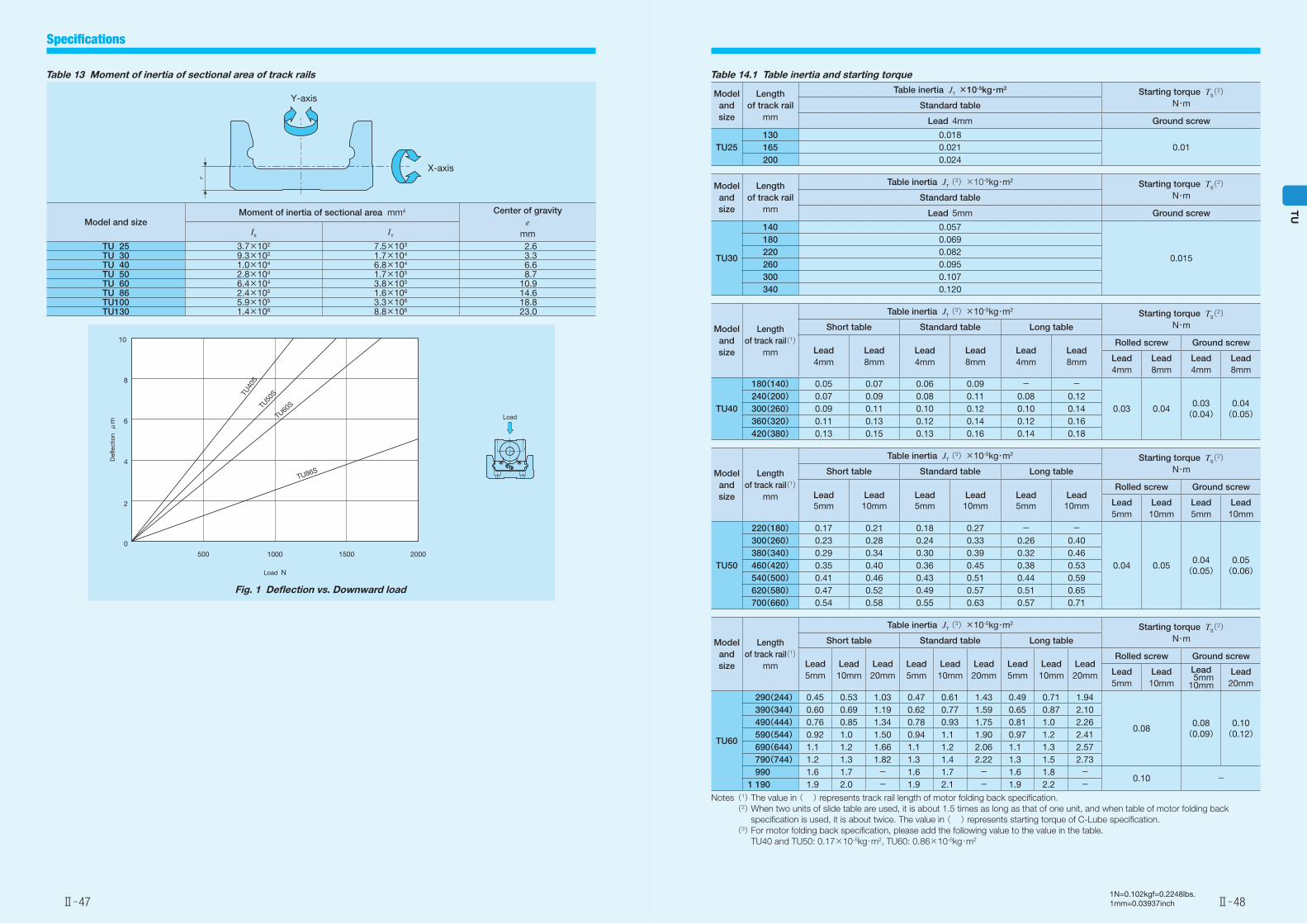
Table 13 Moment of inertia of sectional area of track rails
Model and sizeMoment of inertia of sectional area mm4 Center of gravity
emmIX IY
TU 25 3.7×10² 7.5×10³ 2.6TU 30 9.3×10² 1.7×10⁴ 3.3TU 40 1.0×10⁴ 6.8×10⁴ 6.6TU 50 2.8×10⁴ 1.7×10⁵ 8.7TU 60 6.4×10⁴ 3.8×10⁵ 10.9TU 86 2.4×10⁵ 1.6×10⁶ 14.6TU100 5.9×10⁵ 3.3×10⁶ 18.8TU130 1.4×10⁶ 8.8×10⁶ 23.0
X-axis
Y-axis
e
Fig. 1 Deflection vs. Downward load
TU40
STU
50S
TU60S
TU86S
500
0
2
4
6
8
10
1000 1500 2000
Load N
Defl
ectio
n μ
m
Load
Table 14.1 Table inertia and starting torque
Model and size
Length of track rail
mm
Table inertia JT ×10-5kg・m2 Starting torque TS(2)N・mStandard table
Lead 4mm Ground screw
TU25130 0.018
0.01165 0.021200 0.024
Model and size
Length of track rail
mm
Table inertia JT (3)×10-5kg・m2 Starting torque TS(2)N・mStandard table
Lead 5mm Ground screw
TU30
140 0.057
0.015
180 0.069220 0.082260 0.095300 0.107340 0.120
Model and size
Length of track rail(1)
mm
Table inertia JT (3)×10-5kg・m2 Starting torque TS(2)N・mShort table Standard table Long table
Lead4mm
Lead8mm
Lead4mm
Lead8mm
Lead4mm
Lead8mm
Rolled screw Ground screw
Lead 4mm
Lead 8mm
Lead 4mm
Lead 8mm
TU40
180(140) 0.05 0.07 0.06 0.09 - -
0.03 0.040.03
(0.04)0.04(0.05)
240(200) 0.07 0.09 0.08 0.11 0.08 0.12300(260) 0.09 0.11 0.10 0.12 0.10 0.14360(320) 0.11 0.13 0.12 0.14 0.12 0.16420(380) 0.13 0.15 0.13 0.16 0.14 0.18
Model and size
Length of track rail(1)
mm
Table inertia JT (3)×10-5kg・m2 Starting torque TS(2)N・mShort table Standard table Long table
Lead5mm
Lead10mm
Lead5mm
Lead10mm
Lead5mm
Lead10mm
Rolled screw Ground screw
Lead 5mm
Lead 10mm
Lead 5mm
Lead 10mm
TU50
220(180) 0.17 0.21 0.18 0.27 - -
0.04 0.050.04
(0.05)0.05(0.06)
300(260) 0.23 0.28 0.24 0.33 0.26 0.40380(340) 0.29 0.34 0.30 0.39 0.32 0.46460(420) 0.35 0.40 0.36 0.45 0.38 0.53540(500) 0.41 0.46 0.43 0.51 0.44 0.59620(580) 0.47 0.52 0.49 0.57 0.51 0.65700(660) 0.54 0.58 0.55 0.63 0.57 0.71
Model and size
Length of track rail(1)
mm
Table inertia JT (3)×10-5kg・m2 Starting torque TS(2)N・mShort table Standard table Long table
Lead5mm
Lead10mm
Lead20mm
Lead5mm
Lead10mm
Lead20mm
Lead5mm
Lead10mm
Lead20mm
Rolled screw Ground screw
Lead5mm
Lead 10mm
Lead 5mm10mm
Lead 20mm
TU60
290(244) 0.45 0.53 1.03 0.47 0.61 1.43 0.49 0.71 1.94
0.080.08(0.09)
0.10(0.12)
390(344) 0.60 0.69 1.19 0.62 0.77 1.59 0.65 0.87 2.10490(444) 0.76 0.85 1.34 0.78 0.93 1.75 0.81 1.0 2.26590(544) 0.92 1.0 1.50 0.94 1.1 1.90 0.97 1.2 2.41690(644) 1.1 1.2 1.66 1.1 1.2 2.06 1.1 1.3 2.57790(744) 1.2 1.3 1.82 1.3 1.4 2.22 1.3 1.5 2.73
990 1.6 1.7 - 1.6 1.7 - 1.6 1.8 -0.10 -
1 190 1.9 2.0 - 1.9 2.1 - 1.9 2.2 -Notes (1) The value in ( ) represents track rail length of motor folding back specification. (2) When two units of slide table are used, it is about 1.5 times as long as that of one unit, and when table of motor folding back
specification is used, it is about twice. The value in ( ) represents starting torque of C-Lube specification. (3) For motor folding back specification, please add the following value to the value in the table.
TU40 and TU50: 0.17×10⁻⁵kg・m2, TU60: 0.86×10⁻⁵kg・m2
Ⅱ̶47 Ⅱ̶48
TU
Specifications
1N=0.102kgf=0.2248lbs.1mm=0.03937inch
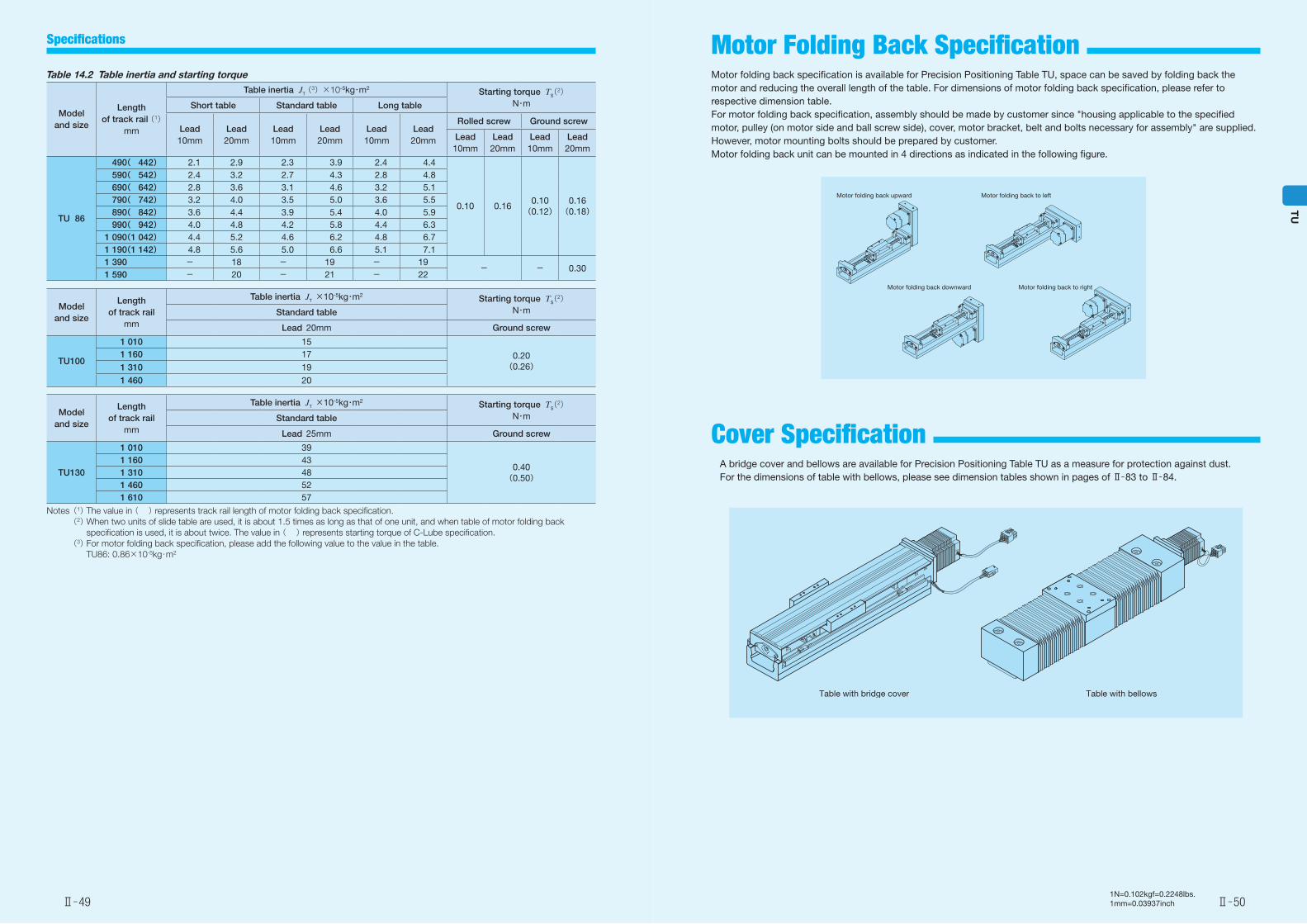
Table 14.2 Table inertia and starting torque
Model and size
Length of track rail (1)
mm
Table inertia JT (3)×10-5kg・m2 Starting torque TS(2)N・mShort table Standard table Long table
Lead10mm
Lead20mm
Lead10mm
Lead20mm
Lead10mm
Lead20mm
Rolled screw Ground screw
Lead 10mm
Lead 20mm
Lead 10mm
Lead 20mm
TU 86
490( 442) 2.1 2.9 2.3 3.9 2.4 4.4
0.10 0.160.10
(0.12)0.16
(0.18)
590( 542) 2.4 3.2 2.7 4.3 2.8 4.8690( 642) 2.8 3.6 3.1 4.6 3.2 5.1790( 742) 3.2 4.0 3.5 5.0 3.6 5.5890( 842) 3.6 4.4 3.9 5.4 4.0 5.9990( 942) 4.0 4.8 4.2 5.8 4.4 6.3
1 090(1 042) 4.4 5.2 4.6 6.2 4.8 6.71 190(1 142) 4.8 5.6 5.0 6.6 5.1 7.11 390 - 18 - 19 - 19
- - 0.301 590 - 20 - 21 - 22
Model and size
Length of track rail
mm
Table inertia JT ×10-5kg・m2 Starting torque TS(2)N・mStandard table
Lead 20mm Ground screw
TU100
1 010 15
0.20(0.26)
1 160 17
1 310 19
1 460 20
Model and size
Length of track rail
mm
Table inertia JT ×10-5kg・m2 Starting torque TS(2)N・mStandard table
Lead 25mm Ground screw
TU130
1 010 39
0.40(0.50)
1 160 431 310 481 460 521 610 57
Notes (1) The value in ( ) represents track rail length of motor folding back specification. (2) When two units of slide table are used, it is about 1.5 times as long as that of one unit, and when table of motor folding back
specification is used, it is about twice. The value in ( ) represents starting torque of C-Lube specification. (3) For motor folding back specification, please add the following value to the value in the table.
TU86: 0.86×10⁻⁵kg・m2
Motor folding back specification is available for Precision Positioning Table TU, space can be saved by folding back the motor and reducing the overall length of the table. For dimensions of motor folding back specification, please refer to respective dimension table.For motor folding back specification, assembly should be made by customer since "housing applicable to the specified motor, pulley (on motor side and ball screw side), cover, motor bracket, belt and bolts necessary for assembly" are supplied. However, motor mounting bolts should be prepared by customer.Motor folding back unit can be mounted in 4 directions as indicated in the following figure.
A bridge cover and bellows are available for Precision Positioning Table TU as a measure for protection against dust.For the dimensions of table with bellows, please see dimension tables shown in pages of Ⅱ̶83 to Ⅱ̶84.
Ⅱ̶49 Ⅱ̶50
TU
Motor Folding Back Specification Specifications
Motor folding back upward Motor folding back to left
Motor folding back downward Motor folding back to right
Table with bridge cover Table with bellows
Cover Specification
1N=0.102kgf=0.2248lbs.1mm=0.03937inch
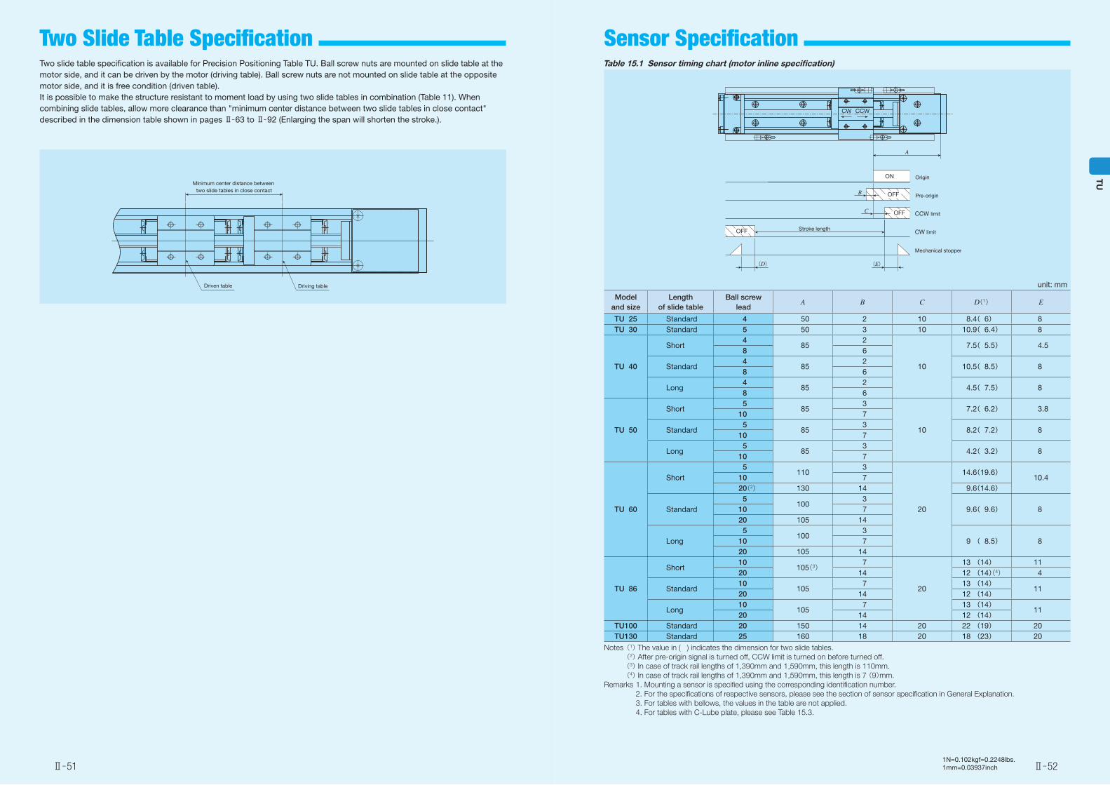
Two slide table specification is available for Precision Positioning Table TU. Ball screw nuts are mounted on slide table at the motor side, and it can be driven by the motor (driving table). Ball screw nuts are not mounted on slide table at the opposite motor side, and it is free condition (driven table).It is possible to make the structure resistant to moment load by using two slide tables in combination (Table 11). When combining slide tables, allow more clearance than "minimum center distance between two slide tables in close contact" described in the dimension table shown in pages Ⅱ̶63 to Ⅱ̶92 (Enlarging the span will shorten the stroke.).
Driving tableDriven table
Minimum center distance between two slide tables in close contact
Table 15.1 Sensor timing chart (motor inline specification)
unit: mm
Model and size
Length of slide table
Ball screw lead
A B C D(1) E
TU 25 Standard 4 50 2 10 8.4( 6) 8TU 30 Standard 5 50 3 10 10.9( 6.4) 8
TU 40
Short4
852
10
7.5( 5.5) 4.58 6
Standard4
852
10.5( 8.5) 88 6
Long4
852
4.5( 7.5) 88 6
TU 50
Short5
853
10
7.2( 6.2) 3.810 7
Standard5
853
8.2( 7.2) 810 7
Long5
853
4.2( 3.2) 810 7
TU 60
Short5
1103
20
14.6(19.6)10.410 7
20(2) 130 14 9.6(14.6)
Standard5
1003
9.6( 9.6) 810 720 105 14
Long5
1003
9 ( 8.5) 810 720 105 14
TU 86
Short10
105(3)7
20
13 (14) 1120 14 12 (14)(4) 4
Standard10
1057 13 (14)
1120 14 12 (14)
Long10
1057 13 (14)
1120 14 12 (14)
TU100 Standard 20 150 14 20 22 (19) 20TU130 Standard 25 160 18 20 18 (23) 20
Notes (1) The value in ( ) indicates the dimension for two slide tables. (2) After pre-origin signal is turned off, CCW limit is turned on before turned off. (3) In case of track rail lengths of 1,390mm and 1,590mm, this length is 110mm. (4) In case of track rail lengths of 1,390mm and 1,590mm, this length is 7 (9)mm.Remarks 1. Mounting a sensor is specified using the corresponding identification number. 2. For the specifications of respective sensors, please see the section of sensor specification in General Explanation. 3. For tables with bellows, the values in the table are not applied. 4. For tables with C-Lube plate, please see Table 15.3.
Origin
Pre-origin
CCW limit
CW limit
Mechanical stopper
(E)(D)
A
CW CCW
OFF
OFF
OFF
ON
B
C
Stroke length
Ⅱ̶51 Ⅱ̶52
TU
Sensor Specification Two Slide Table Specification
1N=0.102kgf=0.2248lbs.1mm=0.03937inch
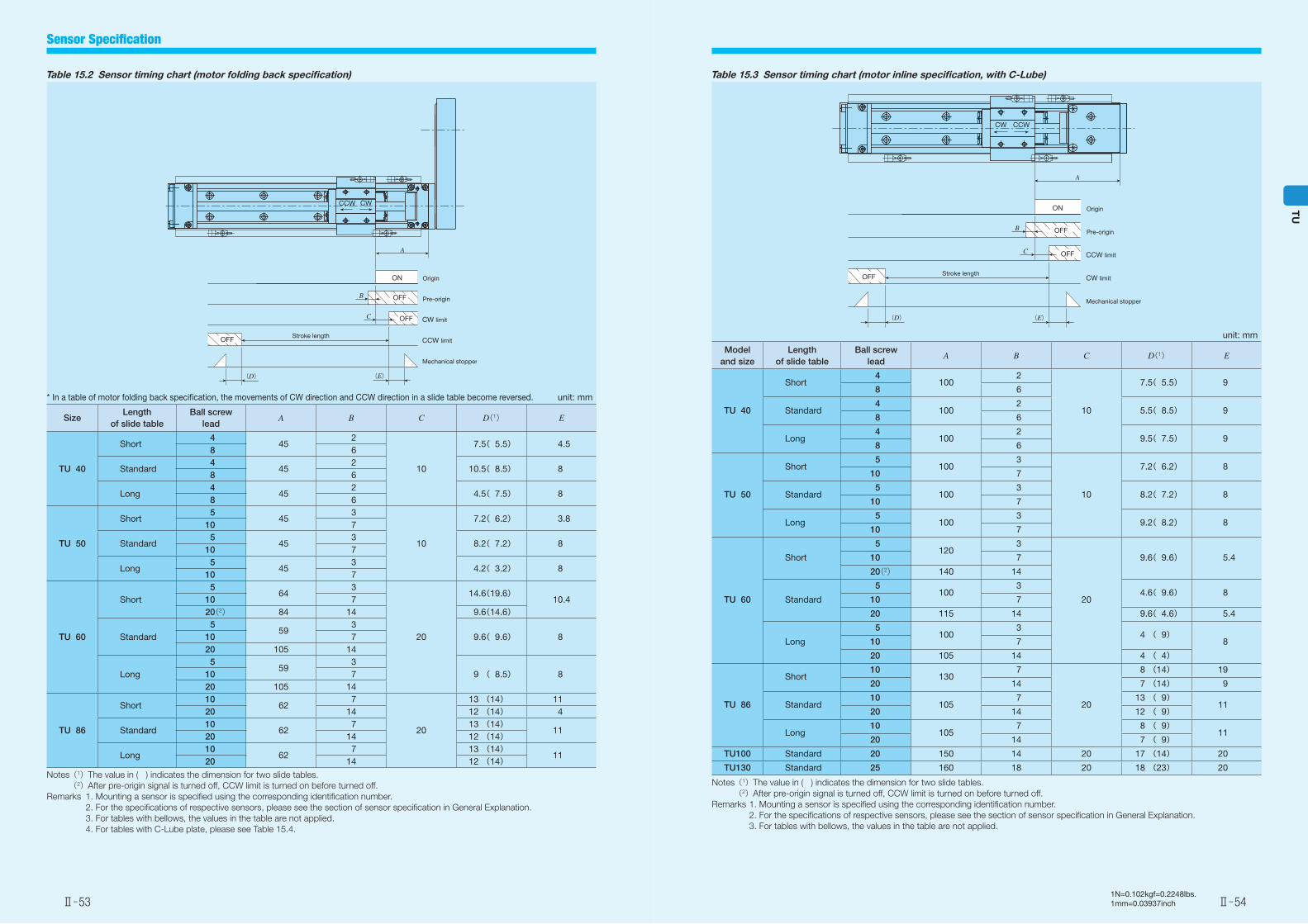
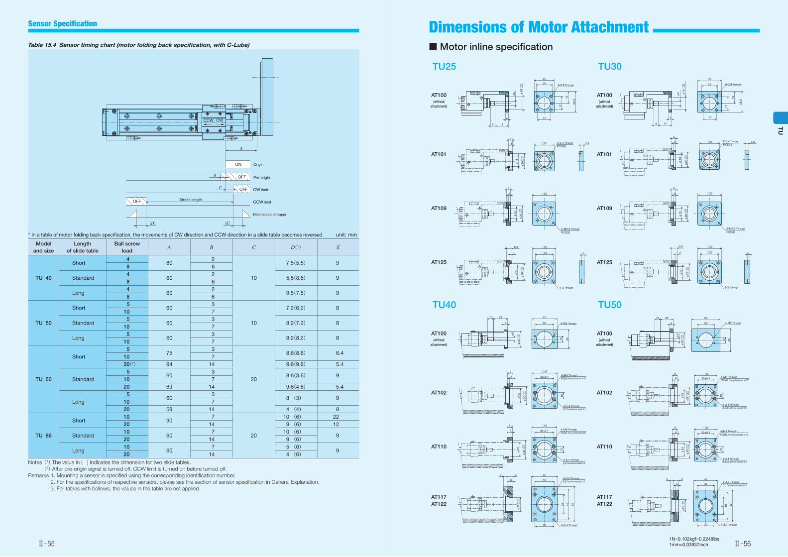
Table 15.2 Sensor timing chart (motor folding back specification)
* In a table of motor folding back specification, the movements of CW direction and CCW direction in a slide table become reversed. unit: mm
SizeLength
of slide tableBall screw
leadA B C D(1) E
TU 40
Short4
452
10
7.5( 5.5) 4.58 6
Standard4
452
10.5( 8.5) 88 6
Long4
452
4.5( 7.5) 88 6
TU 50
Short5
453
10
7.2( 6.2) 3.810 7
Standard5
453
8.2( 7.2) 810 7
Long5
453
4.2( 3.2) 810 7
TU 60
Short5
643
20
14.6(19.6)10.410 7
20(2) 84 14 9.6(14.6)
Standard5
593
9.6( 9.6) 810 720 105 14
Long5
593
9 ( 8.5) 810 720 105 14
TU 86
Short10
627
20
13 (14) 1120 14 12 (14) 4
Standard10
627 13 (14)
1120 14 12 (14)
Long10
627 13 (14)
1120 14 12 (14)
Notes (1)The value in ( ) indicates the dimension for two slide tables. (2)After pre-origin signal is turned off, CCW limit is turned on before turned off.Remarks 1. Mounting a sensor is specified using the corresponding identification number. 2. For the specifications of respective sensors, please see the section of sensor specification in General Explanation. 3. For tables with bellows, the values in the table are not applied. 4. For tables with C-Lube plate, please see Table 15.4.
CCW CW
A
OFF
OFF
OFF
ON Origin
Pre-origin
CW limit
CCW limit
Mechanical stopper
B
C
Stroke length
(E)(D)
Table 15.3 Sensor timing chart (motor inline specification, with C-Lube)
unit: mm
Model and size
Length of slide table
Ball screw lead
A B C D(1) E
TU 40
Short4
1002
10
7.5( 5.5) 98 6
Standard4
1002
5.5( 8.5) 98 6
Long4
1002
9.5( 7.5) 98 6
TU 50
Short5
1003
10
7.2( 6.2) 810 7
Standard5
1003
8.2( 7.2) 810 7
Long5
1003
9.2( 8.2) 810 7
TU 60
Short
5120
3
20
9.6( 9.6) 5.410 7
20(2) 140 14
Standard
5100
34.6( 9.6) 8
10 7
20 115 14 9.6( 4.6) 5.4
Long
5100
34 ( 9)
810 7
20 105 14 4 ( 4)
TU 86
Short10
1307
20
8 (14) 19
20 14 7 (14) 9
Standard10
1057 13 ( 9)
1120 14 12 ( 9)
Long10
1057 8 ( 9)
1120 14 7 ( 9)
TU100 Standard 20 150 14 20 17 (14) 20
TU130 Standard 25 160 18 20 18 (23) 20
Notes (1)The value in ( ) indicates the dimension for two slide tables. (2)After pre-origin signal is turned off, CCW limit is turned on before turned off.Remarks 1. Mounting a sensor is specified using the corresponding identification number. 2. For the specifications of respective sensors, please see the section of sensor specification in General Explanation. 3. For tables with bellows, the values in the table are not applied.
Origin
Pre-origin
CCW limit
CW limit
Mechanical stopper
A
CW CCW
OFF
OFF
OFF
ON
B
C
Stroke length
(E)(D)
Ⅱ̶53 Ⅱ̶54
TU
Sensor Specification
1N=0.102kgf=0.2248lbs.1mm=0.03937inch
Table 15.4 Sensor timing chart (motor folding back specification, with C-Lube)
* In a table of motor folding back specification, the movements of CW direction and CCW direction in a slide table becomes reversed. unit: mm
Model and size
Length of slide table
Ball screw lead
A B C D(1) E
TU 40
Short4
602
10
7.5(5.5) 98 6
Standard4
602
5.5(8.5) 98 6
Long4
602
9.5(7.5) 98 6
TU 50
Short5
603
10
7.2(6.2) 810 7
Standard5
603
8.2(7.2) 810 7
Long5
603
9.2(8.2) 810 7
TU 60
Short5
753
20
8.6(8.6) 6.410 720(2) 94 14 9.6(9.6) 5.4
Standard5
603
8.6(3.6) 910 720 69 14 9.6(4.6) 5.4
Long5
603
8 (3) 910 720 59 14 4 (4) 8
TU 86
Short10
907
20
10 (6) 2220 14 9 (6) 12
Standard10
607 10 (6)
920 14 9 (6)
Long10
607 5 (6)
920 14 4 (6)
Notes (1) The value in ( ) indicates the dimension for two slide tables. (2) After pre-origin signal is turned off, CCW limit is turned on before turned off.Remarks 1. Mounting a sensor is specified using the corresponding identification number. 2. For the specifications of respective sensors, please see the section of sensor specification in General Explanation. 3. For tables with bellows, the values in the table are not applied.
CCW CW
A
OFF
OFF
OFF
ON Origin
Pre-origin
CW limit
CCW limit
Mechanical stopper
B
C
Stroke length
(E)(D)
■ Motor inline specification
TU25 TU30
AT100(without
attachment)
AT100(without
attachment)
AT101 AT101
AT109 AT109
AT125 AT125
TU40 TU50
AT100(without
attachment)
AT100(without
attachment)
AT102 AT102
AT110 AT110
AT117AT122
AT117AT122
4
17
176
25
15
26.3
6-2.9 Through
17
20
+0.
04+
0.02
φ5 φ16
□25 2-3.4 Through
PCD283.53
5
+0.
04+
0.02
φ13
φ20
+0.
04+
0.02
3
5
□30
2-M2.5 Through
PCD33
φ13
φ20
2
6.5
□23
□30
4-3 Through
3
φ13 +
0.04
+0.
02φ
20
4
176
17
30
15
26.3
6-2.9 Through
17
20
+0.
04+
0.02
φ16
φ5
□25 2-3.4 Through
PCD283.53
5
+0.
04+
0.02
φ20φ
13
3
5
□30
2-M2.5 Through
PCD33
+0.
04+
0.02
φ20φ
13
2
6.5
□23
□30
4-3 Through
3
+0.
04+
0.02
φ22φ
13
10
30
2210 40
30
6 4-M3 Through
+0.
04+
0.02
φ26
φ5
6
9
10
4-M4 Through
PCD46, Evenly distributed at 90°
4-3.4 Through
6.5 Counterbore depth 6.5
□40
30±0.1
+0.
04+
0.02
φ30φ
23
4-M3 Through
PCD45, Evenly distributed at 90°
4-3.4 Through
6.5 Counterbore depth 6.5
□40
30±0.16
9
10
+0.
04+
0.02
φ30φ
23
56
30
6
64-3.4 Through6.5 Counterbore depth 3.3
9 42
31
4931
4-3.4 Through
+0.
04+
0.02
φ22
30
50
10 40
4-M3 Through6
2210
+0.
04+
0.02
φ26
φ5
4-M4 Through
PCD46, Evenly distributed at 90°
4-3.4 Through
6.5 Counterbore depth 6.5
□40
30±0.16
9
10
+0.
04+
0.02
φ30φ
23
6
94-M3 Through
PCD45, Evenly distributed at 90°
4-3.4 Through6.5 Counterbore depth 6.5
□40
30±0.1
10
+0.
04+
0.02
φ30φ
23
56
30
9
6
64-3.4 Through6.5 Counterbore depth 3.3
42
31
4931
4-3.4 Through
+0.
04+
0.02
φ22
Ⅱ̶55 Ⅱ̶56
TU
Dimensions of Motor Attachment Sensor Specification
1N=0.102kgf=0.2248lbs.1mm=0.03937inch
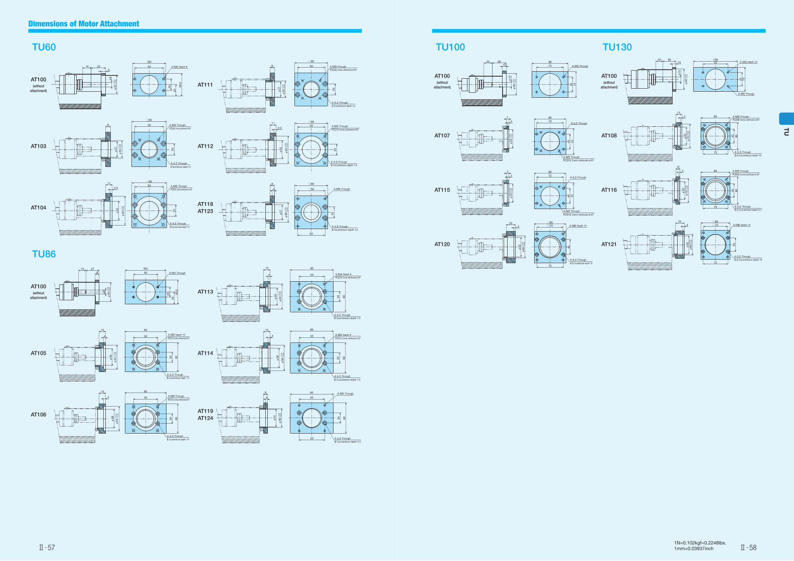
TU60
AT100(without
attachment)AT111
AT103 AT112
AT104AT118AT123
TU86
AT100(without
attachment)AT113
AT105 AT114
AT106AT119AT124
25158
50
(58)
20
20
39.5
4-M4 Depth 8
+0.
04+
0.02
φ32
φ8
□60
4-M4 Through
PCD46, Evenly distributed at 90°
4-4.5 Through
8 Counterbore depth 4.5
20
508
+0.
04+
0.02
φ30φ
27
3.5
11□60
4-M5 Through
PCD70, Evenly distributed at 90°
4-4.5 Through
8 Counterbore depth 7.5
20
50
+0.
04+
0.02
φ50φ
33
4-M3 Through
PCD45, Evenly distributed at 90°
4-4.5 Through
8 Counterbore depth 4.5
□60
20
508
+0.
04+
0.02
φ30φ
27
4-M4 Through
PCD70, Evenly distributed at 90°
4-4.5 Through
8 Counterbore depth 7.5
3.5
11 □60
20
50
+0.
04+
0.02
φ50φ33
8
4-4.5 Through
8 Counterbore depth 4.5
□60
4-M4 Through
20
□50
50
4
+0.
04+
0.02
φ36φ
27
4-M4 Through
20
50
(84)
2549
.5
82715
+0.
04+
0.02
φ39φ
8
13
4-4.5 Through8 Counterbore depth 7.5
85
4-M5 Depth 10
PCD70, Evenly distributed at 90°4 50
20 60
+0.
04+
0.02
φ50φ
34
4
13
4-4.5 Through
8 Counterbore depth 7.5
4-M5 Through
PCD70, Evenly distributed at 90°
85
50
20 60+0.
04+
0.02
φ50φ
39
4-4.5 Through8 Counterbore depth 7.5
4-M4 Depth 8PCD70, Evenly distributed at 90°
13 85
4 50
20 60
+0.
04+
0.02
φ50φ
34
4-4.5 Through
8 Counterbore depth 7.5
4-M4 Depth 8
PCD70, Evenly distributed at 90°4
13 85
5020 60
+0.
04+
0.02
φ50φ
39
8 4-M4 Through
4-4.5 Through
8 Counterbore depth 4.5
85
4
20 60
50
50
+0.
05+
0.02
φ36φ
34
TU100 TU130
AT100(without
attachment)
AT100(without
attachment)
AT107 AT108
AT115 AT116
AT120 AT121
72
40 70
9810
3822
4-M5 Through
+0.
04+
0.02
φ59
φ12
47 85
72
40 70
□85□70
72
40
4-M6 Depth 12
4-5.5 Through
9.5 Counterbore depth 18
254
+0.
04+
0.02
φ60φ
52
4-5.5 Through
4-M5 Through
PCD70, Evenly distributed at 90°
+0.
04+
0.02
φ50
4-5.5 Through
4-M4 Through
PCD70, Evenly distributed at 90°
47 85
72
40 70
+0.
04+
0.02
φ50
2-M5 Depth 1072128
40 70
103820
2-M5 Through
+0.
04+
0.02
φ59
φ15
85
4-5.5 Through
9.5 Counterbore depth 10
4-M6 ThroughPCD90, Evenly distributed at 90°
417
40
72
80
+0.
04+
0.02
φ70φ
52
4-5.5 Through9.5 Counterbore depth 5.4
4-M5 Through
PCD90, Evenly distributed at 90°854
12
40
72
80
+0.
04+
0.02
φ70φ
52
4□85
4-M6 Depth 12
4-5.5 Through
9.5 Counterbore depth 18
25
40
□70
72
+0.
04+
0.02
φ60φ
52
Ⅱ̶57 Ⅱ̶58
TU
Dimensions of Motor Attachment
1N=0.102kgf=0.2248lbs.1mm=0.03937inch
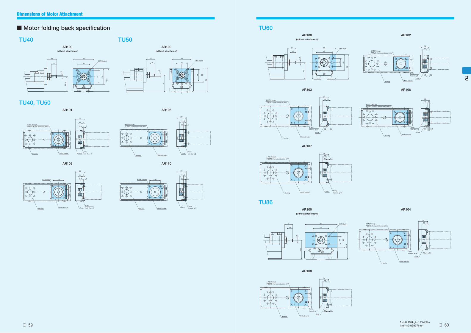
■ Motor folding back specification
TU40 TU50AR100
(without attachment)
AR100(without attachment)
TU40, TU50AR101 AR105
AR109 AR110
10
18
28.5
24
40
24 30
43.5
4-M4 Depth 6φ
510
18
35
24
40
24 30
50
4-M4 Depth 6
φ5
4-M4 Through
PCD46, Evenly distributed at 90°
Motor bracketHousing CoverPulleyhole dia. φ8
2
8
27
11
2.34-M3 Through
PCD45, Evenly distributed at 90°22.3
811
27
PulleyCover
Motor bracketHousinghole dia. φ8
4-3.4 Through 22.3
811
27
Pulley
CoverMotor bracketHousing
□31
hole dia. φ6
22.3
811
27
4-3.4 Through
PulleyCover
Motor bracketHousing hole dia. φ5
□31
TU60AR100
(without attachment)
AR102
AR103 AR106
AR107
TU86AR100
(without attachment)
AR104
AR108
15
21
42
42
60
20 40
62
4-M4 Depth 8
φ8
4-M4 Through
PCD46, Evenly distributed at 90°
3.23.2
616
28
Pulley
Cover
Motor bracketHousing
hole dia. φ8
4-M5 Through
PCD70, Evenly distributed at 90°
3.23.2
616
34
Pulley
Cover
Motor bracketHousing
hole dia. φ14
4-M3 ThroughPCD45, Evenly distributed at 90°
3.23.2
616
28
Pulley
Cover
Motor bracketHousing
hole dia. φ8
4-M4 Through
PCD70, Evenly distributed at 90° 3.23.2
616
34
PulleyCoverMotor bracketHousing hole dia. φ11
15
21
49.5
42
85
20 40
69.5
4-M4 Depth 8
φ8
4-M5 Through
PCD70, Evenly distributed at 90°
3.23.2
616
34
Pulley
Cover
Motor bracketHousing
hole dia. φ14
4-M4 Through
PCD70, Evenly distributed at 90°
3.23.2
616
34
Pulley
CoverMotor bracketHousing
hole dia. φ11
Ⅱ̶59 Ⅱ̶60
TU
Dimensions of Motor Attachment
1N=0.102kgf=0.2248lbs.1mm=0.03937inch
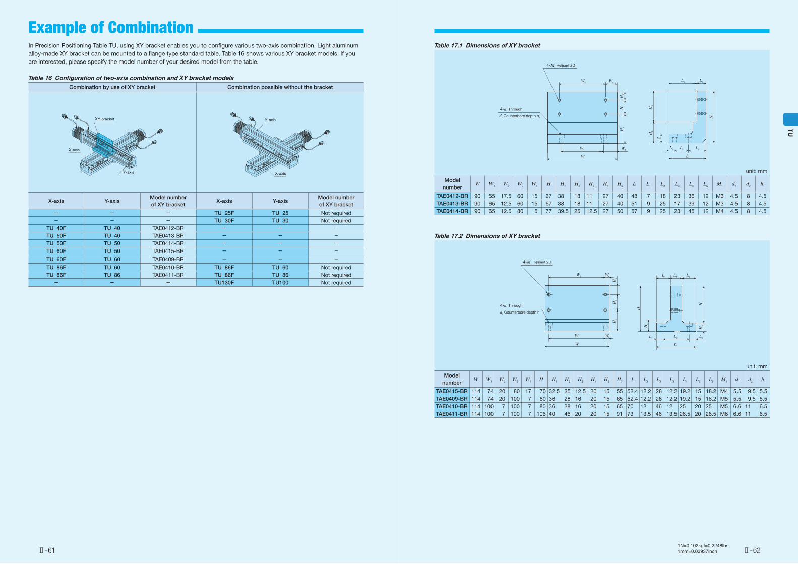
Table 17.1 Dimensions of XY bracket
unit: mm
Model number
W W1 W2 W3 W4 H H1 H2 H3 H4 H5 L L1 L2 L3 L4 L5 M1 d1 d2 h1
TAE0412-BR 90 55 17.5 60 15 67 38 18 11 27 40 48 7 18 23 36 12 M3 4.5 8 4.5TAE0413-BR 90 65 12.5 60 15 67 38 18 11 27 40 51 9 25 17 39 12 M3 4.5 8 4.5TAE0414-BR 90 65 12.5 80 5 77 39.5 25 12.5 27 50 57 9 25 23 45 12 M4 4.5 8 4.5
Table 17.2 Dimensions of XY bracket
unit: mm
Model number
W W1 W2 W3 W4 H H1 H2 H3 H4 H6 H7 L L1 L2 L3 L4 L5 L6 M1 d1 d2 h1
TAE0415-BR 114 74 20 80 17 70 32.5 25 12.5 20 15 55 52.4 12.2 28 12.2 19.2 15 18.2 M4 5.5 9.5 5.5TAE0409-BR 114 74 20 100 7 80 36 28 16 20 15 65 52.4 12.2 28 12.2 19.2 15 18.2 M5 5.5 9.5 5.5TAE0410-BR 114 100 7 100 7 80 36 28 16 20 15 65 70 12 46 12 25 20 25 M5 6.6 11 6.5TAE0411-BR 114 100 7 100 7 106 40 46 20 20 15 91 73 13.5 46 13.5 26.5 20 26.5 M6 6.6 11 6.5
4-M1 Helisert 2D
W3
W
W1W2
W4
H3
H2
H1
4-d1 Through
d2 Counterbore depth h1
L4
L2L1
L
L3
L5 L6
H
H4
H6
H7
In Precision Positioning Table TU, using XY bracket enables you to configure various two-axis combination. Light aluminum alloy-made XY bracket can be mounted to a flange type standard table. Table 16 shows various XY bracket models. If you are interested, please specify the model number of your desired model from the table.
Table 16 Configuration of two-axis combination and XY bracket modelsCombination by use of XY bracket Combination possible without the bracket
X-axis Y-axisModel number of XY bracket
X-axis Y-axisModel number of XY bracket
- - - TU 25F TU 25 Not required- - - TU 30F TU 30 Not required
TU 40F TU 40 TAE0412-BR - - -TU 50F TU 40 TAE0413-BR - - -TU 50F TU 50 TAE0414-BR - - -TU 60F TU 50 TAE0415-BR - - -
TU 60F TU 60 TAE0409-BR - - -
TU 86F TU 60 TAE0410-BR TU 86F TU 60 Not requiredTU 86F TU 86 TAE0411-BR TU 86F TU 86 Not required- - - TU130F TU100 Not required
XY bracket
X-axis
Y-axis
Y-axis
X-axis
4-M1 Helisert 2D
4-d1 Through
W3
W
W1W2
W4L4
L2L1
L
L3
L5
H3
H2
H5
H
H4H
1
d2 Counterbore depth h1
12
Ⅱ̶61 Ⅱ̶62
TU
Example of Combination
1N=0.102kgf=0.2248lbs.1mm=0.03937inch
TU30
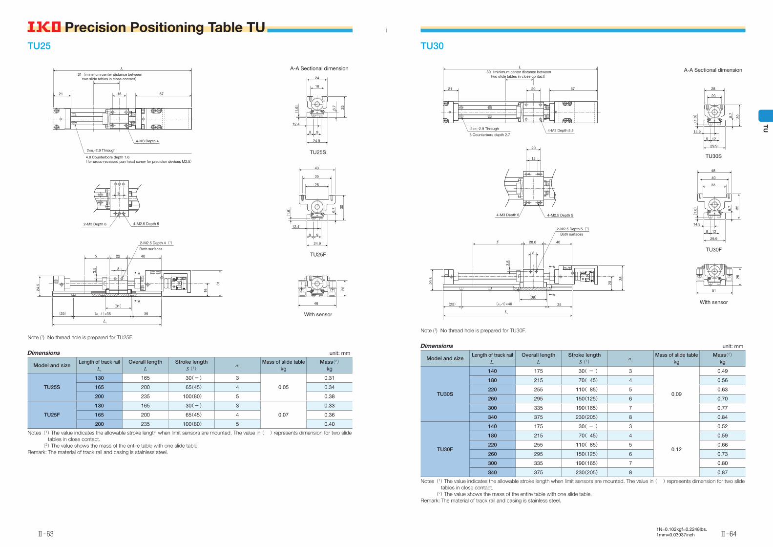
Note (1) No thread hole is prepared for TU30F.
Dimensions unit: mm
Model and sizeLength of track rail
L1
Overall lengthL
Stroke lengthS (1)
n1
Mass of slide tablekg
Mass(2)kg
TU30S
140 175 30( - ) 3
0.09
0.49
180 215 70( 45) 4 0.56
220 255 110( 85) 5 0.63
260 295 150(125) 6 0.70
300 335 190(165) 7 0.77
340 375 230(205) 8 0.84
TU30F
140 175 30( - ) 3
0.12
0.52
180 215 70( 45) 4 0.59
220 255 110( 85) 5 0.66
260 295 150(125) 6 0.73
300 335 190(165) 7 0.80
340 375 230(205) 8 0.87
Notes (1) The value indicates the allowable stroke length when limit sensors are mounted. The value in ( ) represents dimension for two slide tables in close contact.
(2) The value shows the mass of the entire table with one slide table.Remark: The material of track rail and casing is stainless steel.
TU25
Note (1) No thread hole is prepared for TU25F.
Dimensions unit: mm
Model and sizeLength of track rail
L1
Overall lengthL
Stroke lengthS (1)
n1
Mass of slide tablekg
Mass(2)kg
TU25S
130 165 30(-) 3
0.05
0.31
165 200 65(45) 4 0.34
200 235 100(80) 5 0.38
TU25F
130 165 30(-) 3
0.07
0.33
165 200 65(45) 4 0.36
200 235 100(80) 5 0.40
Notes (1) The value indicates the allowable stroke length when limit sensors are mounted. The value in ( ) represents dimension for two slide tables in close contact.
(2) The value shows the mass of the entire table with one slide table.Remark: The material of track rail and casing is stainless steel.
A-A Sectional dimension
TU25S
TU25F
With sensor
21 16 67
31(minimum center distance between two slide tables in close contact)
L
(for cross-recessed pan head screw for precision devices M2.5)
4-M3 Depth 4
9
2-M3 Depth 6 4-M2.5 Depth 5
8
22 40S
3.5
24.5
(25) (n1-1)×35 35
(31)
L1
16
31
2-M2.5 Depth 4(1)Both surfaces
A
A
16
24
6.7
25
(1.
6)
12.4
8 9
24.9
28
35
43
12.4
8 9
24.9
(1.
6) 6.7 30
46
20
2×n1-2.9 Through
4.8 Counterbore depth 1.6
A-A Sectional dimension
TU30S
TU30F
With sensor
21 20 67
L39(minimum center distance between
two slide tables in close contact)
4-M3 Depth 5.5
12
20
4-M3 Depth 6 4-M2.5 Depth 5
8
4028.6S
29.5
(25) (n1-1)×40 35
(38)
3.5
20
35
2-M2.5 Depth 5(1)Both surfaces
20
28
(1.
8)
14.9
9 12
29.9
8.7
30
33
40
48
14.9
9 12
29.9
8.7 35
(1.
8)
51
25
A
A
2×n1-2.9 Through
5 Counterbore depth 2.7
L1
Ⅱ̶63
Precision Positioning Table TU
Ⅱ̶64
TU
Precision Positioning Table TU
1N=0.102kgf=0.2248lbs.1mm=0.03937inch
Dimensions of slide table unit: mm
Model and size
L2 L3 L4 L6 L7 n3 n4
Masskg
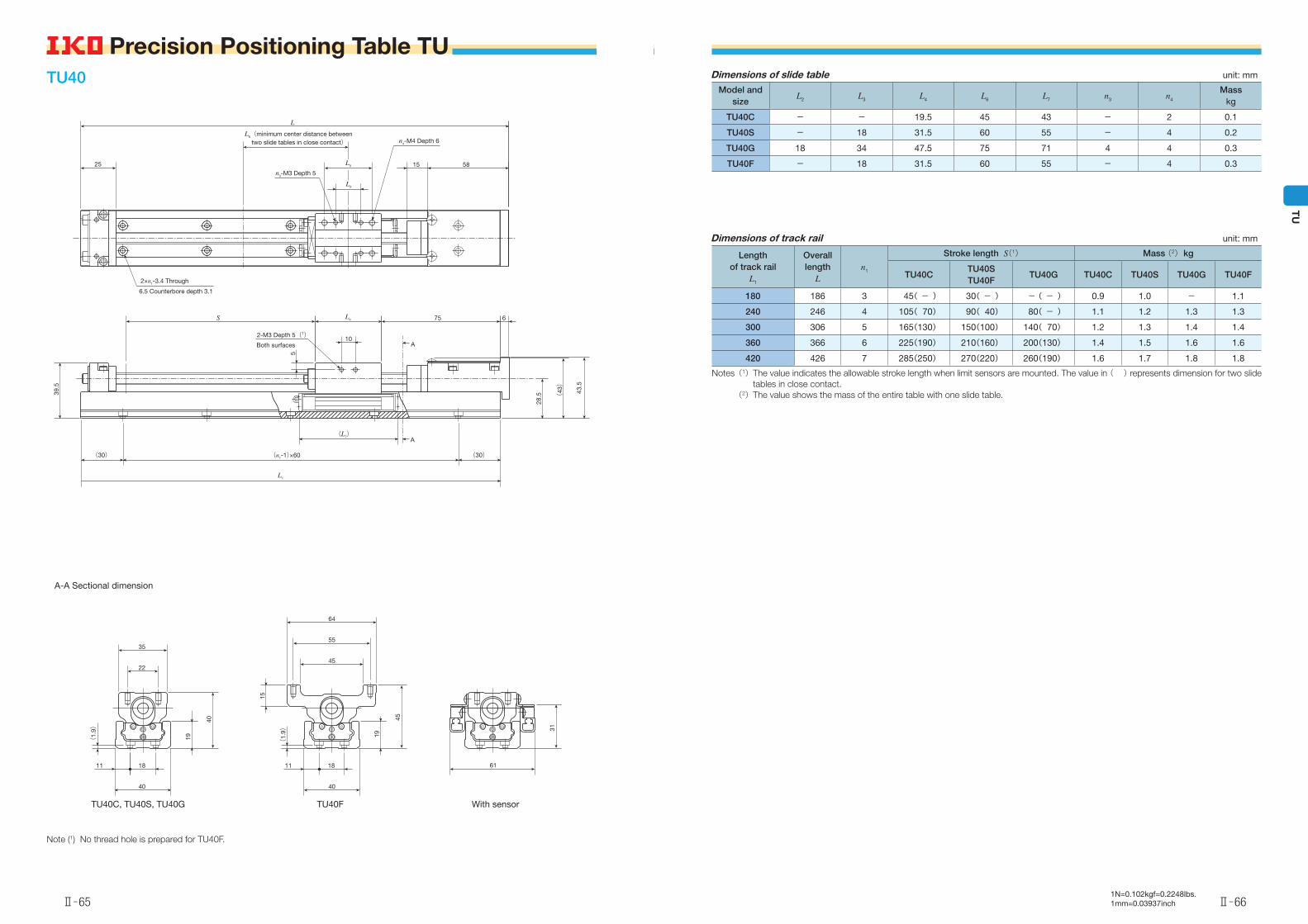
TU40C - - 19.5 45 43 - 2 0.1
TU40S - 18 31.5 60 55 - 4 0.2
TU40G 18 34 47.5 75 71 4 4 0.3
TU40F - 18 31.5 60 55 - 4 0.3
Dimensions of track rail unit: mm
Length of track rail
L1
Overall length
Ln1
Stroke length S(1) Mass (2) kg
TU40CTU40STU40F
TU40G TU40C TU40S TU40G TU40F
180 186 3 45( - ) 30( - ) -( - ) 0.9 1.0 - 1.1
240 246 4 105( 70) 90( 40) 80( - ) 1.1 1.2 1.3 1.3
300 306 5 165(130) 150(100) 140( 70) 1.2 1.3 1.4 1.4
360 366 6 225(190) 210(160) 200(130) 1.4 1.5 1.6 1.6
420 426 7 285(250) 270(220) 260(190) 1.6 1.7 1.8 1.8
Notes (1) The value indicates the allowable stroke length when limit sensors are mounted. The value in ( ) represents dimension for two slide tables in close contact.
(2) The value shows the mass of the entire table with one slide table.
TU40
A-A Sectional dimension
Note (1) No thread hole is prepared for TU40F.
L
25
L6(minimum center distance between two slide tables in close contact)
15 58n3-M3 Depth 5
n4-M4 Depth 6
39.5
S
10
5
(L7)
75 6
28.5 (
43)
43.5
(30)(30)
2-M3 Depth 5(1)Both surfaces A
A
2×n1-3.4 Through
6.5 Counterbore depth 3.1
L3
L2
L4
L1
(n1-1)×60
TU40C, TU40S, TU40G TU40F With sensor
22
35
1811 11
40
(1.
9)
19
40
45
55
64
15
(1.
9) 19
45
18
40
61
31
Ⅱ̶65
Precision Positioning Table TU
Ⅱ̶66
TU
Precision Positioning Table TU
1N=0.102kgf=0.2248lbs.1mm=0.03937inch
Dimensions of slide table unit: mm
Model and size L2 L3 L4 L6 L7 n3
Masskg
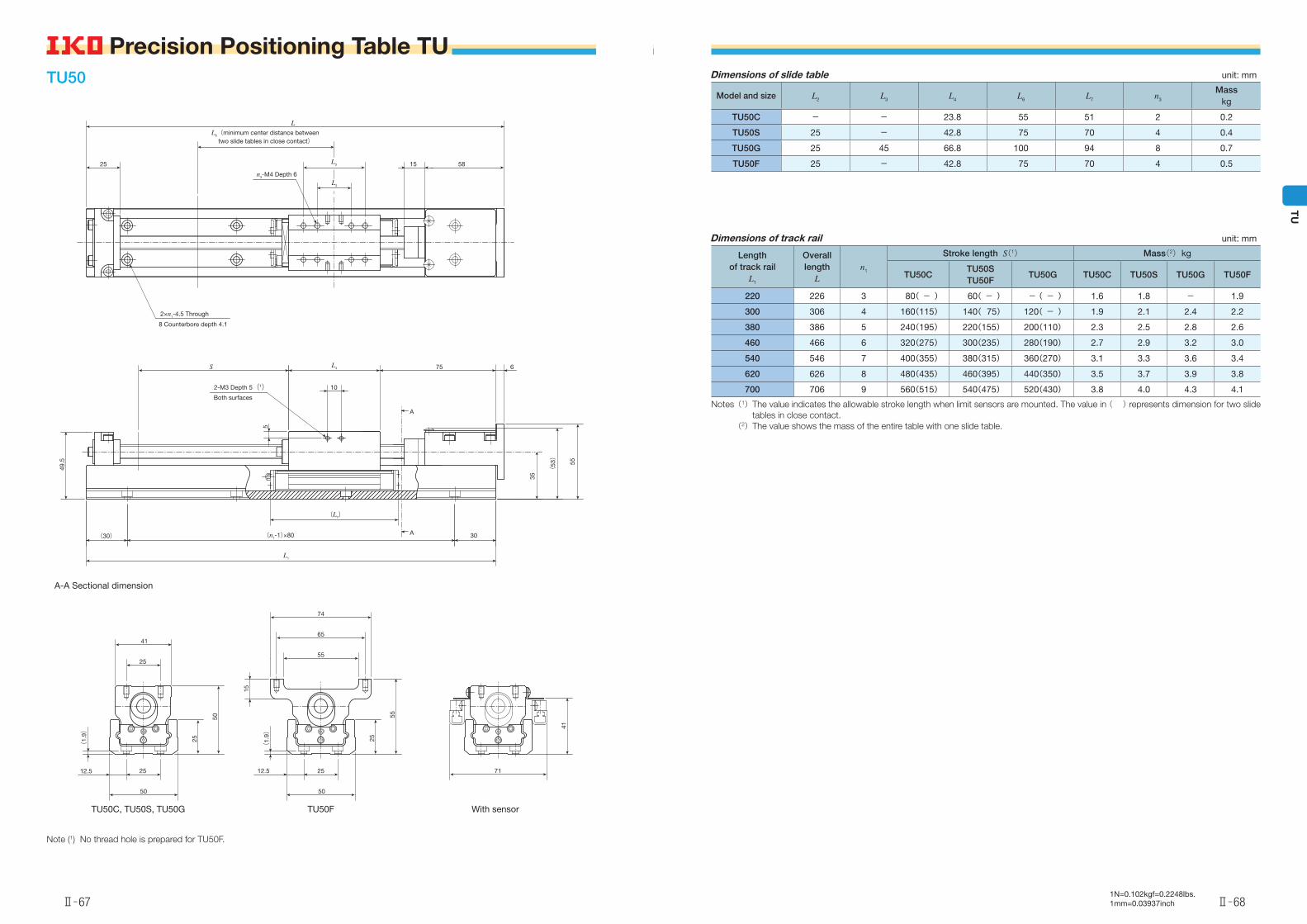
TU50C - - 23.8 55 51 2 0.2
TU50S 25 - 42.8 75 70 4 0.4
TU50G 25 45 66.8 100 94 8 0.7
TU50F 25 - 42.8 75 70 4 0.5
Dimensions of track rail unit: mm
Length of track rail
L1
Overall length
Ln1
Stroke length S(1) Mass(2) kg
TU50CTU50STU50F
TU50G TU50C TU50S TU50G TU50F
220 226 3 80( - ) 60( - ) -( - ) 1.6 1.8 - 1.9
300 306 4 160(115) 140( 75) 120( - ) 1.9 2.1 2.4 2.2
380 386 5 240(195) 220(155) 200(110) 2.3 2.5 2.8 2.6
460 466 6 320(275) 300(235) 280(190) 2.7 2.9 3.2 3.0
540 546 7 400(355) 380(315) 360(270) 3.1 3.3 3.6 3.4
620 626 8 480(435) 460(395) 440(350) 3.5 3.7 3.9 3.8
700 706 9 560(515) 540(475) 520(430) 3.8 4.0 4.3 4.1
Notes (1) The value indicates the allowable stroke length when limit sensors are mounted. The value in ( ) represents dimension for two slide tables in close contact.
(2) The value shows the mass of the entire table with one slide table.
TU50
A-A Sectional dimension
Note (1) No thread hole is prepared for TU50F.
L6(minimum center distance between two slide tables in close contact)
25 15 58
L
n3-M4 Depth 6
10
S 75 6
(30) (n1-1)×80
5
(L7)
3035
(53)
55
2-M3 Depth 5(1)Both surfaces
49.5
A
A
2×n1-4.5 Through
8 Counterbore depth 4.1
L1
L4
L3
L2
TU50C, TU50S, TU50G TU50F With sensor
25
41
25
50
25
50
(1.
9)
55
65
74
2512.5
50
15
(1.
9)
25
55
71
41
12.5
Ⅱ̶67
Precision Positioning Table TU
Ⅱ̶68
TU
Precision Positioning Table TU
1N=0.102kgf=0.2248lbs.1mm=0.03937inch
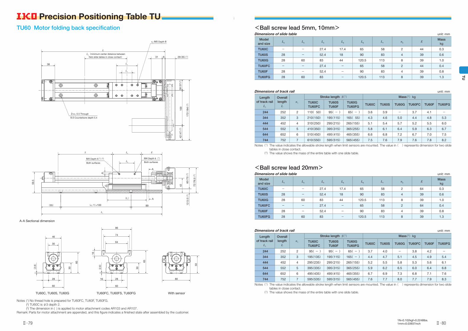
<Ball screw lead 5mm, 10mm>unit: mmDimensions of slide table
Model and size
L2 L3 L4 L5 L6 L7 n3 E E1
Masskg
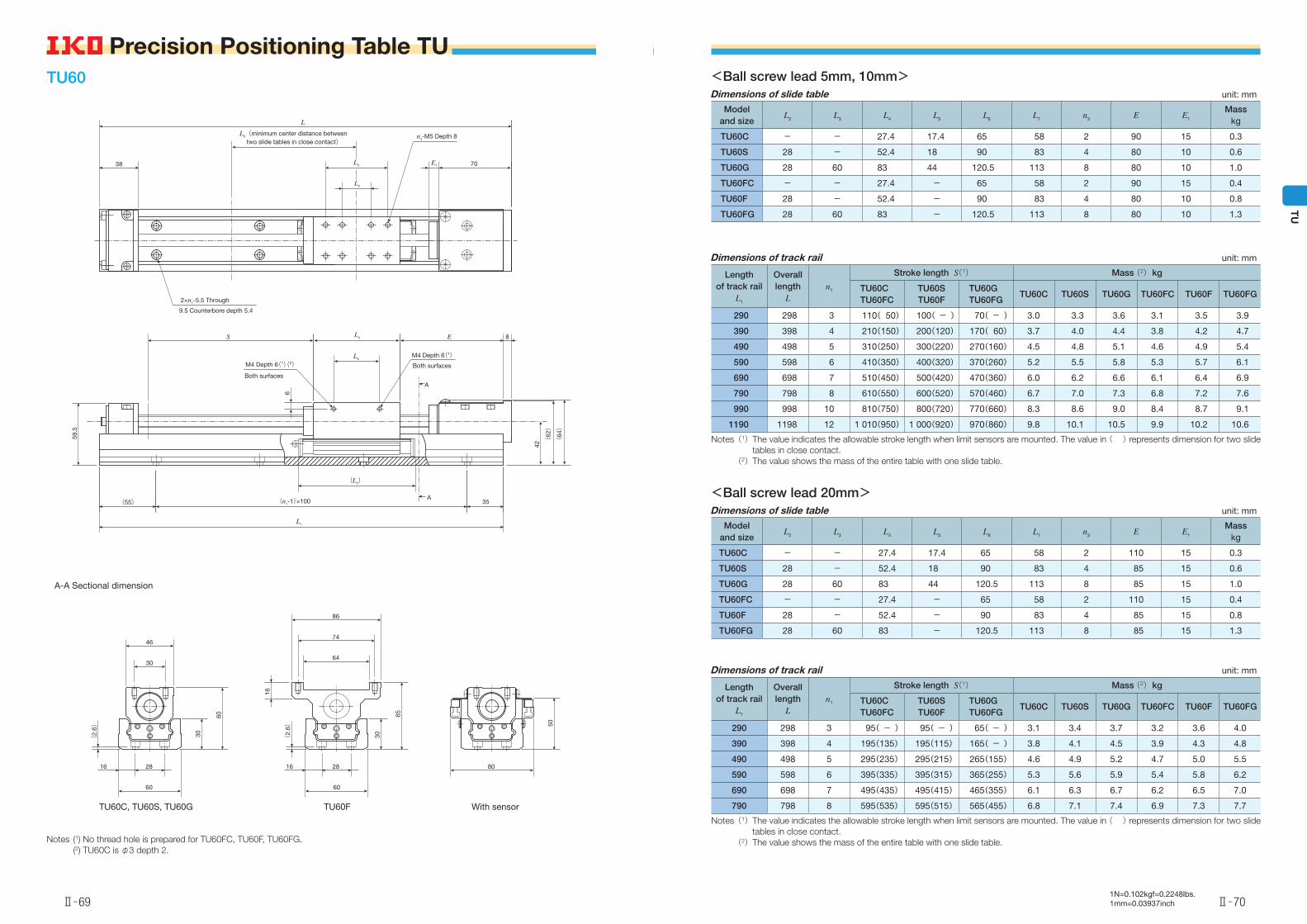
TU60C - - 27.4 17.4 65 58 2 90 15 0.3
TU60S 28 - 52.4 18 90 83 4 80 10 0.6
TU60G 28 60 83 44 120.5 113 8 80 10 1.0
TU60FC - - 27.4 - 65 58 2 90 15 0.4
TU60F 28 - 52.4 - 90 83 4 80 10 0.8
TU60FG 28 60 83 - 120.5 113 8 80 10 1.3
Dimensions of track rail unit: mm
Length of track rail
L1
Overall length
Ln1
Stroke length S(1) Mass (2) kg
TU60CTU60FC
TU60STU60F
TU60GTU60FG
TU60C TU60S TU60G TU60FC TU60F TU60FG
290 298 3 110( 50) 100( - ) 70( - ) 3.0 3.3 3.6 3.1 3.5 3.9
390 398 4 210(150) 200(120) 170( 60) 3.7 4.0 4.4 3.8 4.2 4.7
490 498 5 310(250) 300(220) 270(160) 4.5 4.8 5.1 4.6 4.9 5.4
590 598 6 410(350) 400(320) 370(260) 5.2 5.5 5.8 5.3 5.7 6.1
690 698 7 510(450) 500(420) 470(360) 6.0 6.2 6.6 6.1 6.4 6.9
790 798 8 610(550) 600(520) 570(460) 6.7 7.0 7.3 6.8 7.2 7.6
990 998 10 810(750) 800(720) 770(660) 8.3 8.6 9.0 8.4 8.7 9.1
1190 1198 12 1 010(950) 1 000(920) 970(860) 9.8 10.1 10.5 9.9 10.2 10.6
Notes (1) The value indicates the allowable stroke length when limit sensors are mounted. The value in ( ) represents dimension for two slide tables in close contact.
(2)The value shows the mass of the entire table with one slide table.
<Ball screw lead 20mm>unit: mmDimensions of slide table
Model and size
L2 L3 L4 L5 L6 L7 n3 E E1
Masskg
TU60C - - 27.4 17.4 65 58 2 110 15 0.3
TU60S 28 - 52.4 18 90 83 4 85 15 0.6
TU60G 28 60 83 44 120.5 113 8 85 15 1.0
TU60FC - - 27.4 - 65 58 2 110 15 0.4
TU60F 28 - 52.4 - 90 83 4 85 15 0.8
TU60FG 28 60 83 - 120.5 113 8 85 15 1.3
Dimensions of track rail unit: mm
Length of track rail
L1
Overall length
Ln1
Stroke length S(1) Mass (2) kg
TU60CTU60FC
TU60STU60F
TU60GTU60FG
TU60C TU60S TU60G TU60FC TU60F TU60FG
290 298 3 95( - ) 95( - ) 65( - ) 3.1 3.4 3.7 3.2 3.6 4.0
390 398 4 195(135) 195(115) 165( - ) 3.8 4.1 4.5 3.9 4.3 4.8
490 498 5 295(235) 295(215) 265(155) 4.6 4.9 5.2 4.7 5.0 5.5
590 598 6 395(335) 395(315) 365(255) 5.3 5.6 5.9 5.4 5.8 6.2
690 698 7 495(435) 495(415) 465(355) 6.1 6.3 6.7 6.2 6.5 7.0
790 798 8 595(535) 595(515) 565(455) 6.8 7.1 7.4 6.9 7.3 7.7
Notes (1) The value indicates the allowable stroke length when limit sensors are mounted. The value in ( ) represents dimension for two slide tables in close contact.
(2) The value shows the mass of the entire table with one slide table.
TU60
A-A Sectional dimension
Notes (1) No thread hole is prepared for TU60FC, TU60F, TU60FG. (2) TU60C is φ3 depth 2.
38
L6(minimum center distance between two slide tables in close contact)
E1 70
L
n3-M5 Depth 8
E 8
42
(64)
(62)
59.5
S
M4 Depth 6(1)Both surfacesM4 Depth 6(1)(2)
Both surfaces
6
A
2×n1-5.5 Through
9.5 Counterbore depth 5.4
L3
L2
L4
L5
(55) (n1-1)×100
(L7)
35A
L1
TU60C, TU60S, TU60G TU60F With sensor
30
46
2816 16
60
(2.
6)
30
60
28
60
64
74
86
16
(2.
6)
30
65
80
50
Ⅱ̶69
Precision Positioning Table TU
Ⅱ̶70
TU
Precision Positioning Table TU
1N=0.102kgf=0.2248lbs.1mm=0.03937inch
Dimensions of slide table unit: mm
Model and size
L2 L3 L4 L5 L6 L7 n3 n4
Masskg
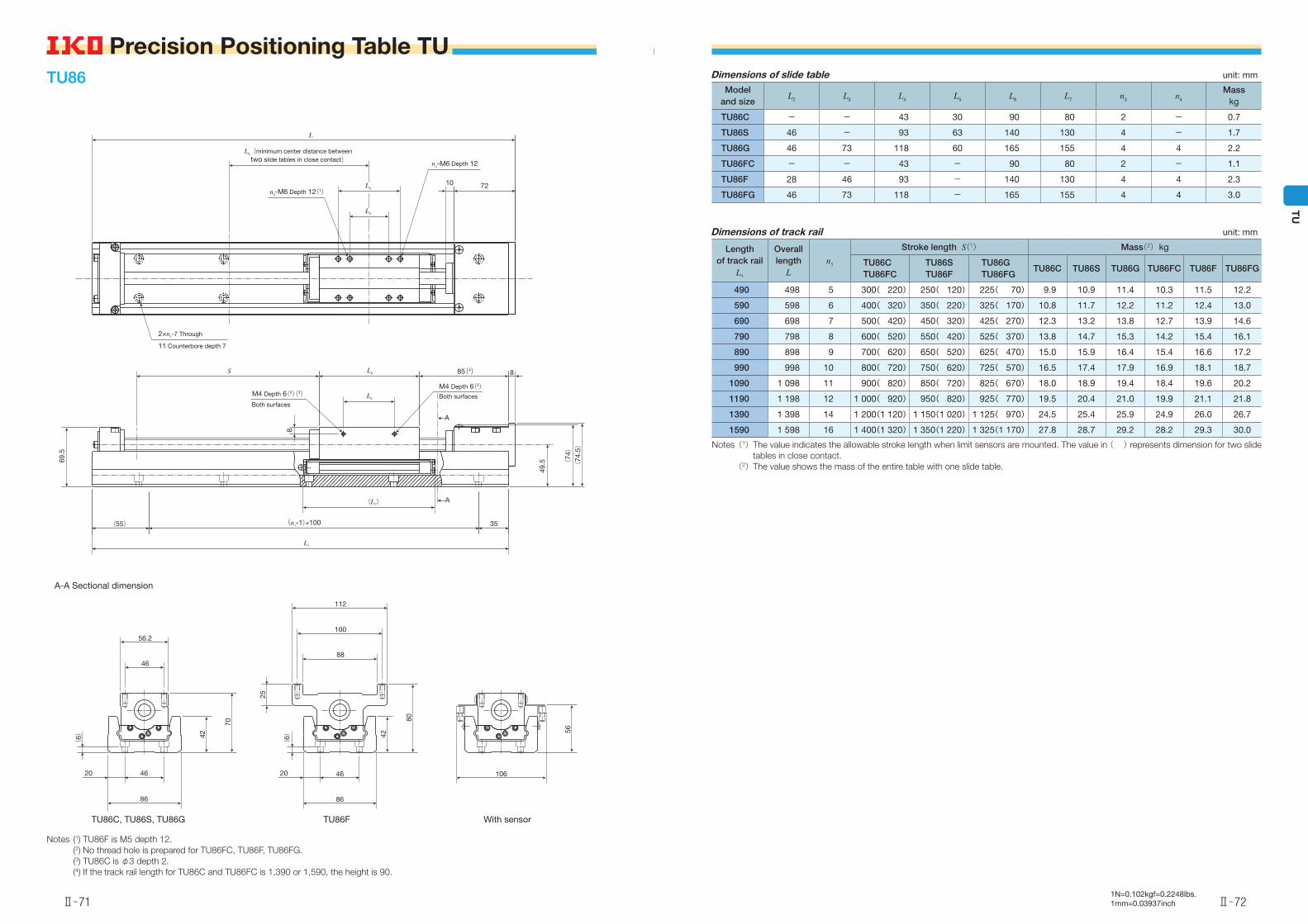
TU86C - - 43 30 90 80 2 - 0.7
TU86S 46 - 93 63 140 130 4 - 1.7
TU86G 46 73 118 60 165 155 4 4 2.2
TU86FC - - 43 - 90 80 2 - 1.1
TU86F 28 46 93 - 140 130 4 4 2.3
TU86FG 46 73 118 - 165 155 4 4 3.0
Dimensions of track rail unit: mm
Length of track rail
L1
Overall length
Ln1
Stroke length S(1) Mass(2) kg
TU86CTU86FC
TU86STU86F
TU86GTU86FG
TU86C TU86S TU86G TU86FC TU86F TU86FG
490 498 5 300( 220) 250( 120) 225( 70) 9.9 10.9 11.4 10.3 11.5 12.2
590 598 6 400( 320) 350( 220) 325( 170) 10.8 11.7 12.2 11.2 12.4 13.0
690 698 7 500( 420) 450( 320) 425( 270) 12.3 13.2 13.8 12.7 13.9 14.6
790 798 8 600( 520) 550( 420) 525( 370) 13.8 14.7 15.3 14.2 15.4 16.1
890 898 9 700( 620) 650( 520) 625( 470) 15.0 15.9 16.4 15.4 16.6 17.2
990 998 10 800( 720) 750( 620) 725( 570) 16.5 17.4 17.9 16.9 18.1 18.7
1090 1 098 11 900( 820) 850( 720) 825( 670) 18.0 18.9 19.4 18.4 19.6 20.2
1190 1 198 12 1 000( 920) 950( 820) 925( 770) 19.5 20.4 21.0 19.9 21.1 21.8
1390 1 398 14 1 200(1 120) 1 150(1 020) 1 125( 970) 24.5 25.4 25.9 24.9 26.0 26.7
1590 1 598 16 1 400(1 320) 1 350(1 220) 1 325(1 170) 27.8 28.7 29.2 28.2 29.3 30.0
Notes (1) The value indicates the allowable stroke length when limit sensors are mounted. The value in ( ) represents dimension for two slide tables in close contact.
(2) The value shows the mass of the entire table with one slide table.
TU86
A-A Sectional dimension
Notes (1) TU86F is M5 depth 12. (2) No thread hole is prepared for TU86FC, TU86F, TU86FG. (3) TU86C is φ3 depth 2. (4) If the track rail length for TU86C and TU86FC is 1,390 or 1,590, the height is 90.
L2
L3
L6(minimum center distance between two slide tables in close contact)
10 72
L
n4-M6 Depth 12
n3-M6 Depth 12(1)
L5
L4 85(4) 8
8
35
(L7)
(55) (n1-1)×100
L1
S
M4 Depth 6(2)(3)
Both surfaces
M4 Depth 6(2)Both surfaces
49.5 (
74)
(74
.5)
69.5
A
A
2×n1-7 Through
11 Counterbore depth 7
TU86C, TU86S, TU86G TU86F With sensor
46
4620 20
56.2
86
(6) 42
70
88
100
112
46
86
(6)
25
42
80
106
56
Ⅱ̶71
Precision Positioning Table TU
Ⅱ̶72
TU
Precision Positioning Table TU
1N=0.102kgf=0.2248lbs.1mm=0.03937inch
TU130
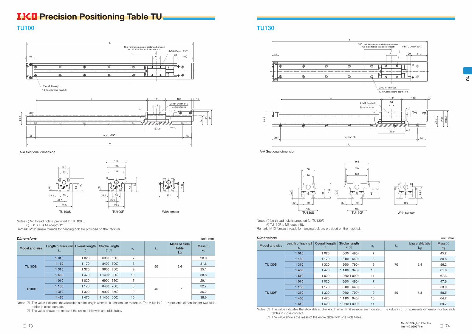
A-A Sectional dimension
Notes (1) No thread hole is prepared for TU130F. (2) TU130F is M8 depth 15.Remark: M12 female threads for hanging bolt are provided on the track rail.
Dimensions unit: mm
Model and sizeLength of track rail
L1
Overall lengthL
Stroke lengthS (1)
n1 L2
Mass of slide table kg
Mass(2)kg
TU130S
1 010 1 020 660( 490) 7
70 5.4
45.2
1 160 1 170 810( 640) 8 50.6
1 310 1 320 960( 790) 9 56.2
1 460 1 470 1 110( 940) 10 61.8
1 610 1 620 1 260(1 090) 11 67.3
TU130F
1 010 1 020 660( 490) 7
50 7.8
47.6
1 160 1 170 810( 640) 8 53.0
1 310 1 320 960( 790) 9 58.6
1 460 1 470 1 110( 940) 10 64.2
1 610 1 620 1 260(1 090) 11 69.7
Notes (1) The value indicates the allowable stroke length when limit sensors are mounted. The value in ( ) represents dimension for two slide tables in close contact.
(2) The value shows the mass of the entire table with one slide table.
L2 20 110
180(minimum center distance between two slide tables in close contact)
45
L
4-M10 Depth 20(2)
34
132 140 10
72.5
(10
4)
(10
7.5)
55
(178)
(55)
L1
S
8
2-M4 Depth 6(1)
Both surfaces
99.5
A
A
2×n1-11 Through
17.5 Counterbore depth 10.6
(n1-1)×150
70
88
7030
130
(9.
4)
65
100
134
150
168
70
130
(9.
4)
65
110
150
74.5
30
TU100
A-A Sectional dimension
Notes (1) No thread hole is prepared for TU100F. (2) TU100F is M6 depth 12.Remark: M12 female threads for hanging bolt are provided on the track rail.
Dimensions unit: mm
Model and sizeLength of track rail
L1
Overall lengthL
Stroke lengthS (1)
n1 L2
Mass of slide table
kg
Mass(2)kg
TU100S
1 010 1 020 690( 550) 7
50 2.6
28.0
1 160 1 170 840( 700) 8 31.6
1 310 1 320 990( 850) 9 35.1
1 460 1 470 1 140(1 000) 10 38.8
TU100F
1 010 1 020 690( 550) 7
46 3.7
29.1
1 160 1 170 840( 700) 8 32.7
1 310 1 320 990( 850) 9 36.2
1 460 1 470 1 140(1 000) 10 39.9
Notes (1) The value indicates the allowable stroke length when limit sensors are mounted. The value in ( ) represents dimension for two slide tables in close contact.
(2) The value shows the mass of the entire table with one slide table.
45 L2
155(minimum center distance between two slide tables in close contact)
4-M8 Depth 15(2)20
100
L
34
111 130 10
58 (84)
(93)
55
6
(153.2)
(55) (n1-1)×150
L1
S
79.5
2-M4 Depth 6(1)Both surfaces
A
A
2×n1-9 Through
14 Counterbore depth 9
TU100S TU100F With sensor
50
65.2
50
49.5
99.5
52
80
(8)
24.5
102
115
128
50
49.5
24.5
99.5
52
90
121
61.3
(8)
TU130S TU130F With sensor
Ⅱ̶73
Precision Positioning Table TU
Ⅱ̶74
TU
Precision Positioning Table TU
1N=0.102kgf=0.2248lbs.1mm=0.03937inch
Dimensions of slide table unit: mm
Model and size
L2 L3 L4 L6 L7 n3 n4
Masskg
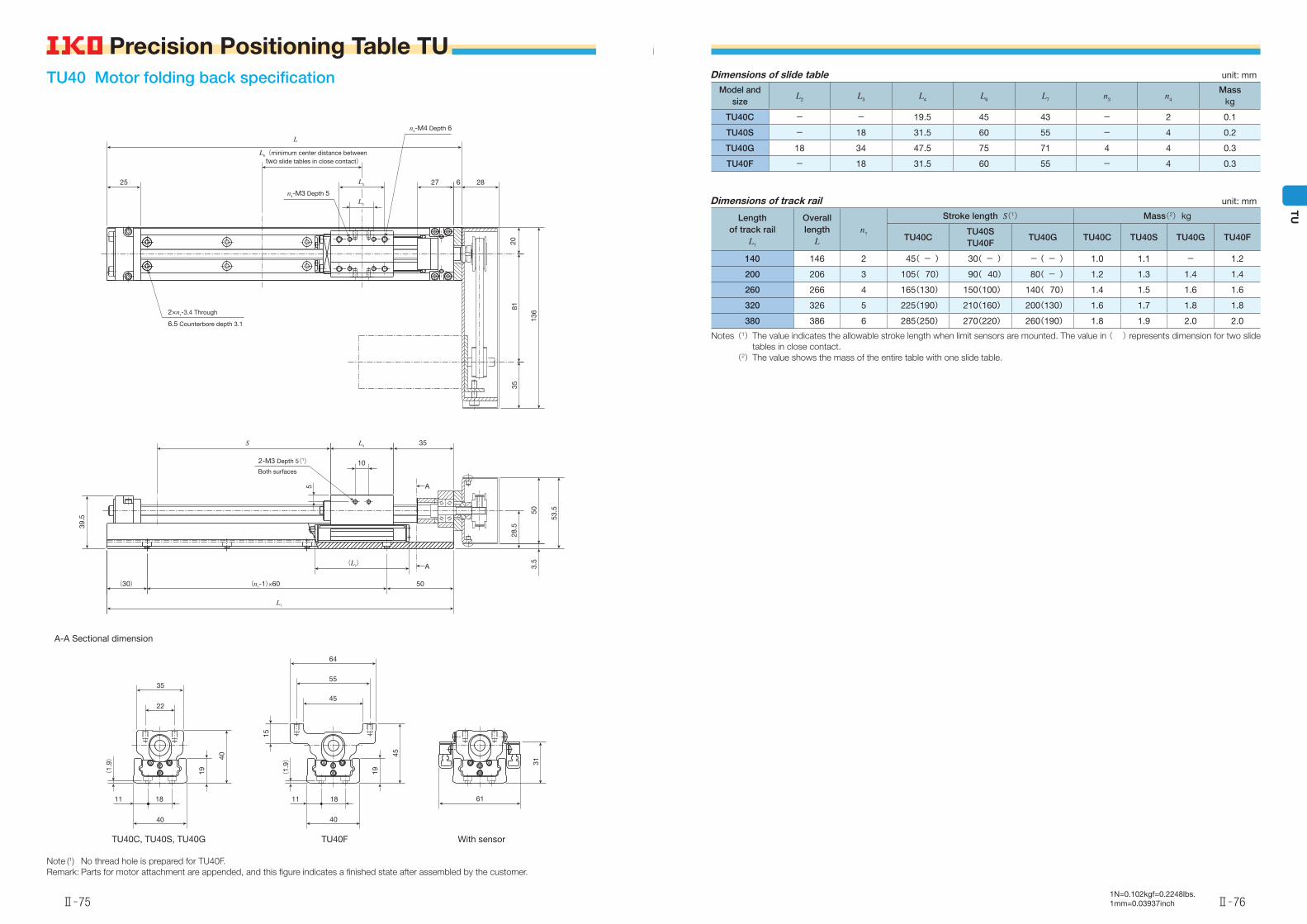
TU40C - - 19.5 45 43 - 2 0.1
TU40S - 18 31.5 60 55 - 4 0.2
TU40G 18 34 47.5 75 71 4 4 0.3
TU40F - 18 31.5 60 55 - 4 0.3
Dimensions of track rail unit: mm
Length of track rail
L1
Overall length
Ln1
Stroke length S(1) Mass(2) kg
TU40CTU40STU40F
TU40G TU40C TU40S TU40G TU40F
140 146 2 45( - ) 30( - ) -( - ) 1.0 1.1 - 1.2
200 206 3 105( 70) 90( 40) 80( - ) 1.2 1.3 1.4 1.4
260 266 4 165(130) 150(100) 140( 70) 1.4 1.5 1.6 1.6
320 326 5 225(190) 210(160) 200(130) 1.6 1.7 1.8 1.8
380 386 6 285(250) 270(220) 260(190) 1.8 1.9 2.0 2.0
Notes (1) The value indicates the allowable stroke length when limit sensors are mounted. The value in ( ) represents dimension for two slide tables in close contact.
(2) The value shows the mass of the entire table with one slide table.
TU40 Motor folding back specification
A-A Sectional dimension
Note (1) No thread hole is prepared for TU40F.Remark: Parts for motor attachment are appended, and this figure indicates a finished state after assembled by the customer.
25
L2
L3
L6(minimum center distance between two slide tables in close contact)
L
2081
35
136
627 28
n4-M4 Depth 6
n3-M3 Depth 5
10
L4 35S
39.5
(30) (n1-1)×60
(L7)
50
L1
28.5
3.5
50
53.5
5
2-M3 Depth 5(1)Both surfaces
A
A
2×n1-3.4 Through
6.5 Counterbore depth 3.1
22
35
1811 11
40
19
40
(1.
9)
45
55
64
15
(1.
9)
19
45
18
40
61
31
TU40C, TU40S, TU40G TU40F With sensor
Ⅱ̶75
Precision Positioning Table TU
Ⅱ̶76
TU
Precision Positioning Table TU
1N=0.102kgf=0.2248lbs.1mm=0.03937inch
Dimensions of slide table unit: mm
Model and size L2 L3 L4 L6 L7 n3
Masskg
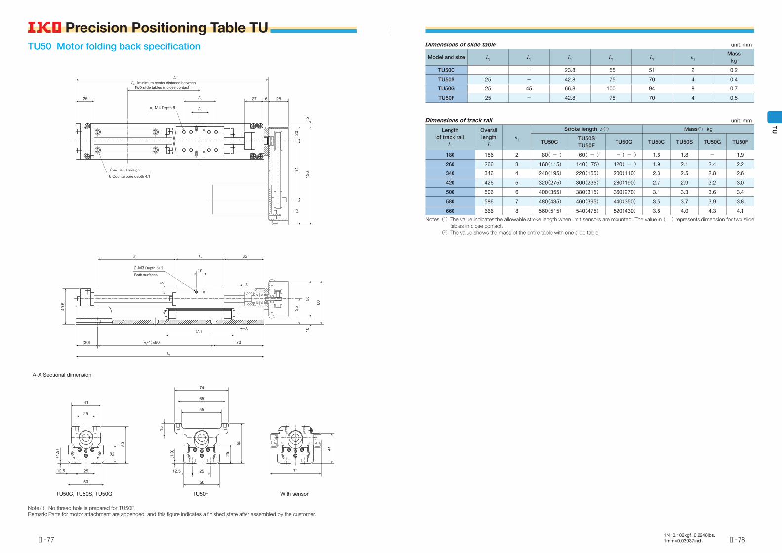
TU50C - - 23.8 55 51 2 0.2
TU50S 25 - 42.8 75 70 4 0.4
TU50G 25 45 66.8 100 94 8 0.7
TU50F 25 - 42.8 75 70 4 0.5
Dimensions of track rail unit: mm
Length of track rail
L1
Overall length
Ln1
Stroke length S(1) Mass(2) kg
TU50CTU50STU50F
TU50G TU50C TU50S TU50G TU50F
180 186 2 80( - ) 60( - ) -( - ) 1.6 1.8 - 1.9
260 266 3 160(115) 140( 75) 120( - ) 1.9 2.1 2.4 2.2
340 346 4 240(195) 220(155) 200(110) 2.3 2.5 2.8 2.6
420 426 5 320(275) 300(235) 280(190) 2.7 2.9 3.2 3.0
500 506 6 400(355) 380(315) 360(270) 3.1 3.3 3.6 3.4
580 586 7 480(435) 460(395) 440(350) 3.5 3.7 3.9 3.8
660 666 8 560(515) 540(475) 520(430) 3.8 4.0 4.3 4.1
Notes (1) The value indicates the allowable stroke length when limit sensors are mounted. The value in ( ) represents dimension for two slide tables in close contact.
(2) The value shows the mass of the entire table with one slide table.
TU50 Motor folding back specification
A-A Sectional dimension
Note (1) No thread hole is prepared for TU50F.Remark: Parts for motor attachment are appended, and this figure indicates a finished state after assembled by the customer.
25
L2
L3
L6(minimum center distance between two slide tables in close contact)
27 6 28
L
8120
35
136
5
n3-M4 Depth 6
10
L4 35
5
35
50
60
10
(30) (n1-1)×80
(L7)
70
L1
S
2-M3 Depth 5(1)
2×n1-4.5 Through
8 Counterbore depth 4.1
Both surfaces
49.5
A
A
25
41
2512.5
50
(1.
9)
25
50
55
65
74
50
25
55
15
(1.
9)
71
41
2512.5
TU50C, TU50S, TU50G TU50F With sensor
Ⅱ̶77
Precision Positioning Table TU
Ⅱ̶78
TU
Precision Positioning Table TU
1N=0.102kgf=0.2248lbs.1mm=0.03937inch
<Ball screw lead 5mm, 10mm>Dimensions of slide table unit: mm
Model and size
L2 L3 L4 L5 L6 L7 n3 EMass
kg
TU60C - - 27.4 17.4 65 58 2 44 0.3
TU60S 28 - 52.4 18 90 83 4 39 0.6
TU60G 28 60 83 44 120.5 113 8 39 1.0
TU60FC - - 27.4 - 65 58 2 44 0.4
TU60F 28 - 52.4 - 90 83 4 39 0.8
TU60FG 28 60 83 - 120.5 113 8 39 1.3
Dimensions of track rail unit: mm
Length of track rail
L1
Overall length
Ln1
Stroke length S(1) Mass(2) kg
TU60CTU60FC
TU60STU60F
TU60GTU60FG
TU60C TU60S TU60G TU60FC TU60F TU60FG
244 252 2 110( 50) 95( - ) 65( - ) 3.6 3.9 - 3.7 4.1 -
344 352 3 210(150) 195(115) 165( 55) 4.3 4.6 5.0 4.4 4.8 5.3
444 452 4 310(250) 295(215) 265(155) 5.1 5.4 5.7 5.2 5.5 6.0
544 552 5 410(350) 395(315) 365(255) 5.8 6.1 6.4 5.9 6.3 6.7
644 652 6 510(450) 495(415) 465(355) 6.6 6.8 7.2 6.7 7.0 7.5
744 752 7 610(550) 595(515) 565(455) 7.5 7.6 7.9 7.6 7.8 8.2
Notes (1) The value indicates the allowable stroke length when limit sensors are mounted. The value in ( ) represents dimension for two slide tables in close contact.
(2) The value shows the mass of the entire table with one slide table.
<Ball screw lead 20mm>Dimensions of slide table unit: mm
Model and size
L2 L3 L4 L5 L6 L7 n3 EMass
kg
TU60C - - 27.4 17.4 65 58 2 64 0.3
TU60S 28 - 52.4 18 90 83 4 39 0.6
TU60G 28 60 83 44 120.5 113 8 39 1.0
TU60FC - - 27.4 - 65 58 2 64 0.4
TU60F 28 - 52.4 - 90 83 4 39 0.8
TU60FG 28 60 83 - 120.5 113 8 39 1.3
Dimensions of track rail unit: mm
Length of track rail
L1
Overall length
Ln1
Stroke length S(1) Mass(2) kg
TU60CTU60FC
TU60STU60F
TU60GTU60FG
TU60C TU60S TU60G TU60FC TU60F TU60FG
244 252 2 95( - ) 95( - ) 65( - ) 3.7 4.0 - 3.8 4.2 -
344 352 3 195(135) 195(115) 165( - ) 4.4 4.7 5.1 4.5 4.9 5.4
444 452 4 295(235) 295(215) 265(155) 5.2 5.5 5.8 5.3 5.6 6.1
544 552 5 395(335) 395(315) 365(255) 5.9 6.2 6.5 6.0 6.4 6.8
644 652 6 495(435) 495(415) 465(355) 6.7 6.9 7.3 6.8 7.1 7.6
744 752 7 595(535) 595(515) 565(455) 7.6 7.7 8.0 7.7 7.9 8.3
Notes (1) The value indicates the allowable stroke length when limit sensors are mounted. The value in ( ) represents dimension for two slide tables in close contact.
(2) The value shows the mass of the entire table with one slide table.
TU60 Motor folding back specification
A-A Sectional dimension
Notes (1) No thread hole is prepared for TU60FC, TU60F, TU60FG. (2) TU60C is φ3 depth 2. (3) The dimension in ( ) is applied to motor attachment codes AR103 and AR107.Remark: Parts for motor attachment are appended, and this figure indicates a finished state after assembled by the customer.
38
L2
L3
L6(minimum center distance between two slide tables in close contact) 31 8 29(35)(3)
30(
37)(
3 )42(
47)(
3 )10
0
172 (
184)(
3 )
L
n3-M5 Depth 8
L5
L4 ES
(n1-1)×100(55)
(L7)
89
L1
42
60(
73)(
3 )12(
5.5)(
3 )
72(
78.5)(
3 )
6
M4 Depth 6(1)Both surfaces
M4 Depth 6(1)(2)
2×n1-5.5 Through
9.5 Counterbore depth 5.4
Both surfaces
59.5
A
A
30
46
28 16
60
30
60
(2.
6)
64
74
86
28
60
16
(2.
6)
30
65
50
80
TU60C, TU60S, TU60G TU60FC, TU60FS, TU60FG With sensor
Ⅱ̶79
Precision Positioning Table TU
Ⅱ̶80
TU
Precision Positioning Table TU
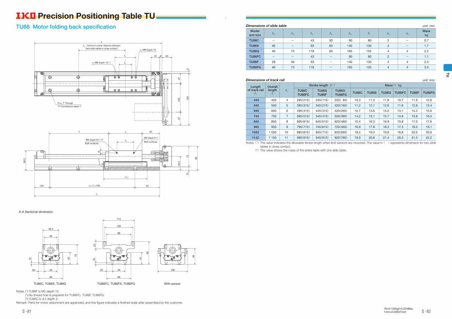
1N=0.102kgf=0.2248lbs.1mm=0.03937inch
Dimensions of slide table unit: mm
Model and size
L2 L3 L4 L5 L6 L7 n3 n4
Masskg
TU86C - - 43 30 90 80 2 - 0.7
TU86S 46 - 93 63 140 130 4 - 1.7
TU86G 46 73 118 60 165 155 4 4 2.2
TU86FC - - 43 - 90 80 2 - 1.1
TU86F 28 46 93 - 140 130 4 4 2.3
TU86FG 46 73 118 - 165 155 4 4 3.0
Dimensions of track rail unit: mm
Length of track rail
L1
Overall length
Ln1
Stroke length S(1) Mass(2) kg
TU86CTU86FC
TU86STU86F
TU86GTU86FG
TU86C TU86S TU86G TU86FC TU86F TU86FG
442 450 4 295(215) 245(115) 220( 65) 10.3 11.3 11.8 10.7 11.9 12.6
542 550 5 395(315) 345(215) 320(165) 11.2 12.1 12.6 11.6 12.8 13.4
642 650 6 495(415) 445(315) 420(265) 12.7 13.6 14.2 13.1 14.3 15.0
742 750 7 595(515) 545(415) 520(365) 14.2 15.1 15.7 14.6 15.8 16.5
842 850 8 695(615) 645(515) 620(465) 15.4 16.3 16.8 15.8 17.0 17.6
942 950 9 795(715) 745(615) 720(565) 16.9 17.8 18.3 17.3 18.5 19.1
1042 1 050 10 895(815) 845(715) 820(665) 18.4 19.3 19.8 18.8 20.0 20.6
1142 1 150 11 995(915) 945(815) 920(765) 19.9 20.8 21.4 20.3 21.5 22.2
Notes (1) The value indicates the allowable stroke length when limit sensors are mounted. The value in ( ) represents dimension for two slide tables in close contact.
(2) The value shows the mass of the entire table with one slide table.
TU86 Motor folding back specification
A-A Sectional dimension
Notes (1) TU86F is M5 depth 12. (2) No thread hole is prepared for TU86FC, TU86F, TU86FG. (3) TU86C is φ3 depth 2.Remark: Parts for motor attachment are appended, and this figure indicates a finished state after assembled by the customer.
L2
L3
L6(minimum center distance between two slide tables in close contact)
31 8 35
L
3710
047
184
6
n4-M6 Depth 12
L5
L4
8
42S
(55) (n1-1)×100 87
(L7)
L1
49.5
1373
86
69.5
M4 Depth 6(2)
Both surfacesM4 Depth 6(2)(3)
Both surfaces
n3-M6 Depth 12(1)
2×n1-7 Through
11 Counterbore depth 7
46
56.2
4620
86
(6) 42
70
88
100
112
(6) 42
80
25
56
1064620
86
TU86C, TU86S, TU86G TU86FC, TU86FS, TU86FG With sensor
Ⅱ̶81
Precision Positioning Table TU
Ⅱ̶82
TU
Precision Positioning Table TU
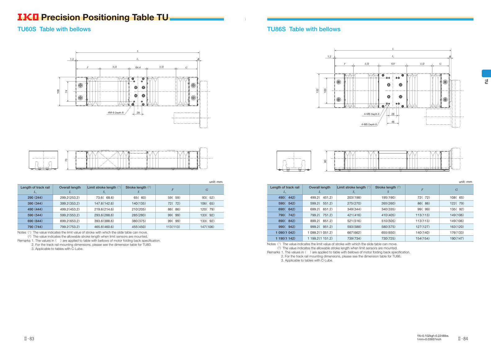
1N=0.102kgf=0.2248lbs.1mm=0.03937inch
TU86S Table with bellows
unit: mm
Length of track railL1
Overall lengthL
Limit stroke length (1)S1
Stroke length (2)S
F G
490( 442) 499.2( 451.2) 203(198) 195(190) 72( 72) 108( 65)
590( 542) 599.2( 551.2) 275(270) 265(260) 86( 86) 122( 79)
690( 642) 699.2( 651.2) 349(344) 340(335) 99( 99) 135( 92)
790( 742) 799.2( 751.2) 421(416) 410(405) 113(113) 149(106)
890( 842) 899.2( 851.2) 521(516) 510(505) 113(113) 149(106)
990( 942) 999.2( 951.2) 593(588) 580(575) 127(127) 163(120)
1 090(1 042) 1 099.2(1 051.2) 667(662) 655(650) 140(140) 176(133)
1 190(1 142) 1 199.2(1 151.2) 739(734) 730(725) 154(154) 190(147)
Notes (1) The value indicates the limit value of stroke with which the slide table can move. (2) The value indicates the allowable stroke length when limit sensors are mounted.Remarks 1. The values in ( ) are applied to table with bellows of motor folding back specification. 2. For the track rail mounting dimensions, please see the dimension table for TU86. 3. Applicable to tables with C-Lube.
107S1/2F S1/2 G
8L11.2
L
100
132
28
464-M5 Depth 8
4-M6 Depth 8
80
TU60S Table with bellows
unit: mm
Length of track railL1
Overall lengthL
Limit stroke length (1)S1
Stroke length (2)S
F G
290 (244) 299.2(253.2) 73.6( 68.6) 65( 60) 59( 59) 93( 52)
390 (344) 399.2(353.2) 147.6(142.6) 140(135) 72( 72) 106( 65)
490 (444) 499.2(453.2) 219.6(214.6) 210(205) 86( 86) 120( 79)
590 (544) 599.2(553.2) 293.6(288.6) 285(280) 99( 99) 133( 92)
690 (644) 699.2(653.2) 393.6(388.6) 380(375) 99( 99) 133( 92)
790 (744) 799.2(753.2) 465.6(460.6) 455(450) 113(113) 147(106)
Notes (1) The value indicates the limit value of stroke with which the slide table can move. (2) The value indicates the allowable stroke length when limit sensors are mounted.Remarks 1. The values in ( ) are applied to table with bellows of motor folding back specification. 2. For the track rail mounting dimensions, please see the dimension table for TU60. 3. Applicable to tables with C-Lube.
64.4 S1/2S1/2 G
8L1
L
1.2
F7410
6
70
4M-5 Depth 8 28
Ⅱ̶83
Precision Positioning Table TU
Ⅱ̶84
TU
Precision Positioning Table TU
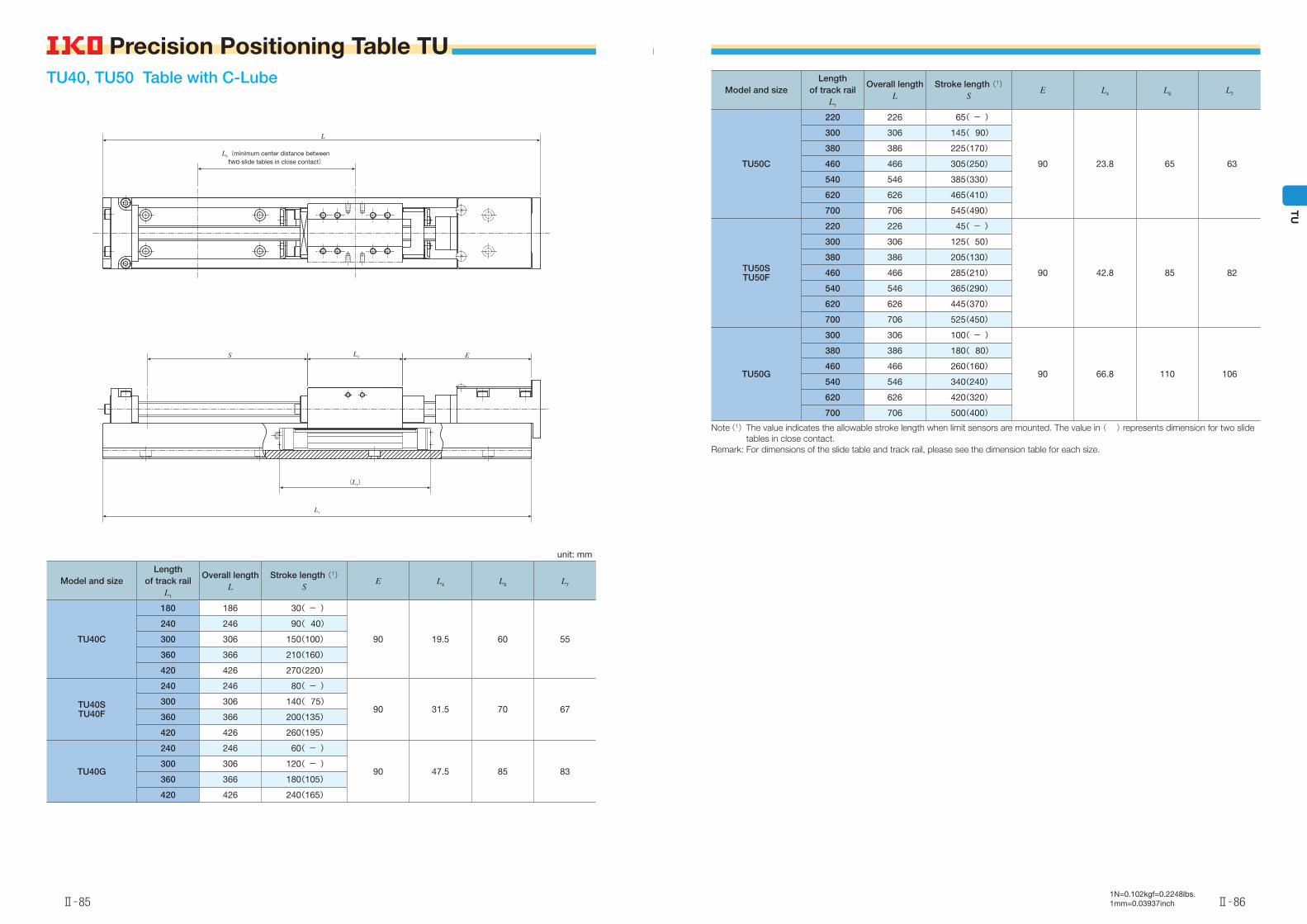
1N=0.102kgf=0.2248lbs.1mm=0.03937inch
Model and sizeLength
of track railL1
Overall lengthL
Stroke length (1)S
E L4 L6 L7
TU50C
220 226 65( - )
90 23.8 65 63
300 306 145( 90)
380 386 225(170)
460 466 305(250)
540 546 385(330)
620 626 465(410)
700 706 545(490)
TU50STU50F
220 226 45( - )
90 42.8 85 82
300 306 125( 50)
380 386 205(130)
460 466 285(210)
540 546 365(290)
620 626 445(370)
700 706 525(450)
TU50G
300 306 100( - )
90 66.8 110 106
380 386 180( 80)
460 466 260(160)
540 546 340(240)
620 626 420(320)
700 706 500(400)
Note (1) The value indicates the allowable stroke length when limit sensors are mounted. The value in ( ) represents dimension for two slide tables in close contact.
Remark: For dimensions of the slide table and track rail, please see the dimension table for each size.
TU40, TU50 Table with C-Lube
unit: mm
Model and sizeLength
of track railL1
Overall lengthL
Stroke length (1)S
E L4 L6 L7
TU40C
180 186 30( - )
90 19.5 60 55
240 246 90( 40)
300 306 150(100)
360 366 210(160)
420 426 270(220)
TU40STU40F
240 246 80( - )
90 31.5 70 67300 306 140( 75)
360 366 200(135)
420 426 260(195)
TU40G
240 246 60( - )
90 47.5 85 83300 306 120( - )
360 366 180(105)
420 426 240(165)
L6(minimum center distance between two slide tables in close contact)
L
L4 ES
(L7)
L1
Ⅱ̶85
Precision Positioning Table TU
Ⅱ̶86
TU
Precision Positioning Table TU
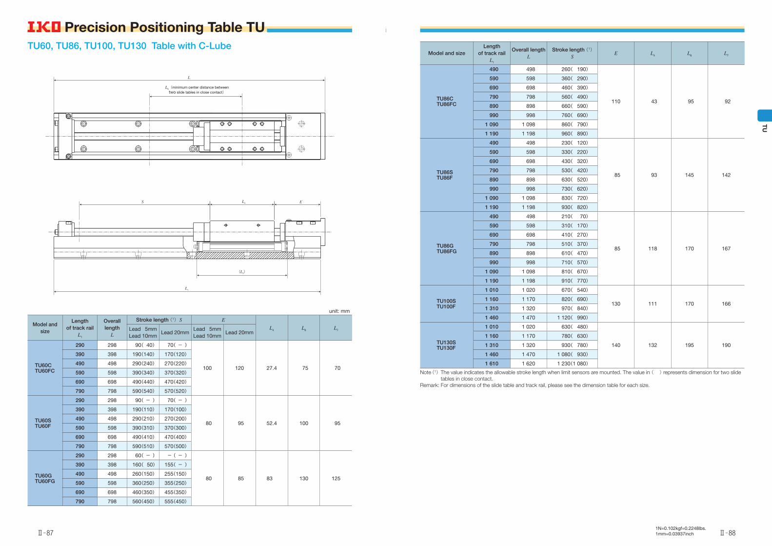
1N=0.102kgf=0.2248lbs.1mm=0.03937inch
Model and sizeLength
of track railL1
Overall lengthL
Stroke length (1)S
E L4 L6 L7
TU86CTU86FC
490 498 260( 190)
110 43 95 92
590 598 360( 290)
690 698 460( 390)
790 798 560( 490)
890 898 660( 590)
990 998 760( 690)
1 090 1 098 860( 790)
1 190 1 198 960( 890)
TU86STU86F
490 498 230( 120)
85 93 145 142
590 598 330( 220)
690 698 430( 320)
790 798 530( 420)
890 898 630( 520)
990 998 730( 620)
1 090 1 098 830( 720)
1 190 1 198 930( 820)
TU86GTU86FG
490 498 210( 70)
85 118 170 167
590 598 310( 170)
690 698 410( 270)
790 798 510( 370)
890 898 610( 470)
990 998 710( 570)
1 090 1 098 810( 670)
1 190 1 198 910( 770)
TU100STU100F
1 010 1 020 670( 540)
130 111 170 1661 160 1 170 820( 690)
1 310 1 320 970( 840)
1 460 1 470 1 120( 990)
TU130STU130F
1 010 1 020 630( 480)
140 132 195 190
1 160 1 170 780( 630)
1 310 1 320 930( 780)
1 460 1 470 1 080( 930)
1 610 1 620 1 230(1 080)
Note (1) The value indicates the allowable stroke length when limit sensors are mounted. The value in ( ) represents dimension for two slide tables in close contact.
Remark: For dimensions of the slide table and track rail, please see the dimension table for each size.
TU60, TU86, TU100, TU130 Table with C-Lube
unit: mm
Model and size
Length of track rail
L1
Overall length
L
Stroke length (1) S E
L4 L6 L7Lead 5mmLead 10mm
Lead 20mmLead 5mmLead 10mm
Lead 20mm
TU60CTU60FC
290 298 90( 40) 70( - )
100 120 27.4 75 70
390 398 190(140) 170(120)
490 498 290(240) 270(220)
590 598 390(340) 370(320)
690 698 490(440) 470(420)
790 798 590(540) 570(520)
TU60STU60F
290 298 90( - ) 70( - )
80 95 52.4 100 95
390 398 190(110) 170(100)
490 498 290(210) 270(200)
590 598 390(310) 370(300)
690 698 490(410) 470(400)
790 798 590(510) 570(500)
TU60GTU60FG
290 298 60( - ) -( - )
80 85 83 130 125
390 398 160( 50) 155( - )
490 498 260(150) 255(150)
590 598 360(250) 355(250)
690 698 460(350) 455(350)
790 798 560(450) 555(450)
L
L4 ES
(L7)
L1
L6(minimum center distance between two slide tables in close contact)
Ⅱ̶87
Precision Positioning Table TU
Ⅱ̶88
TU
Precision Positioning Table TU
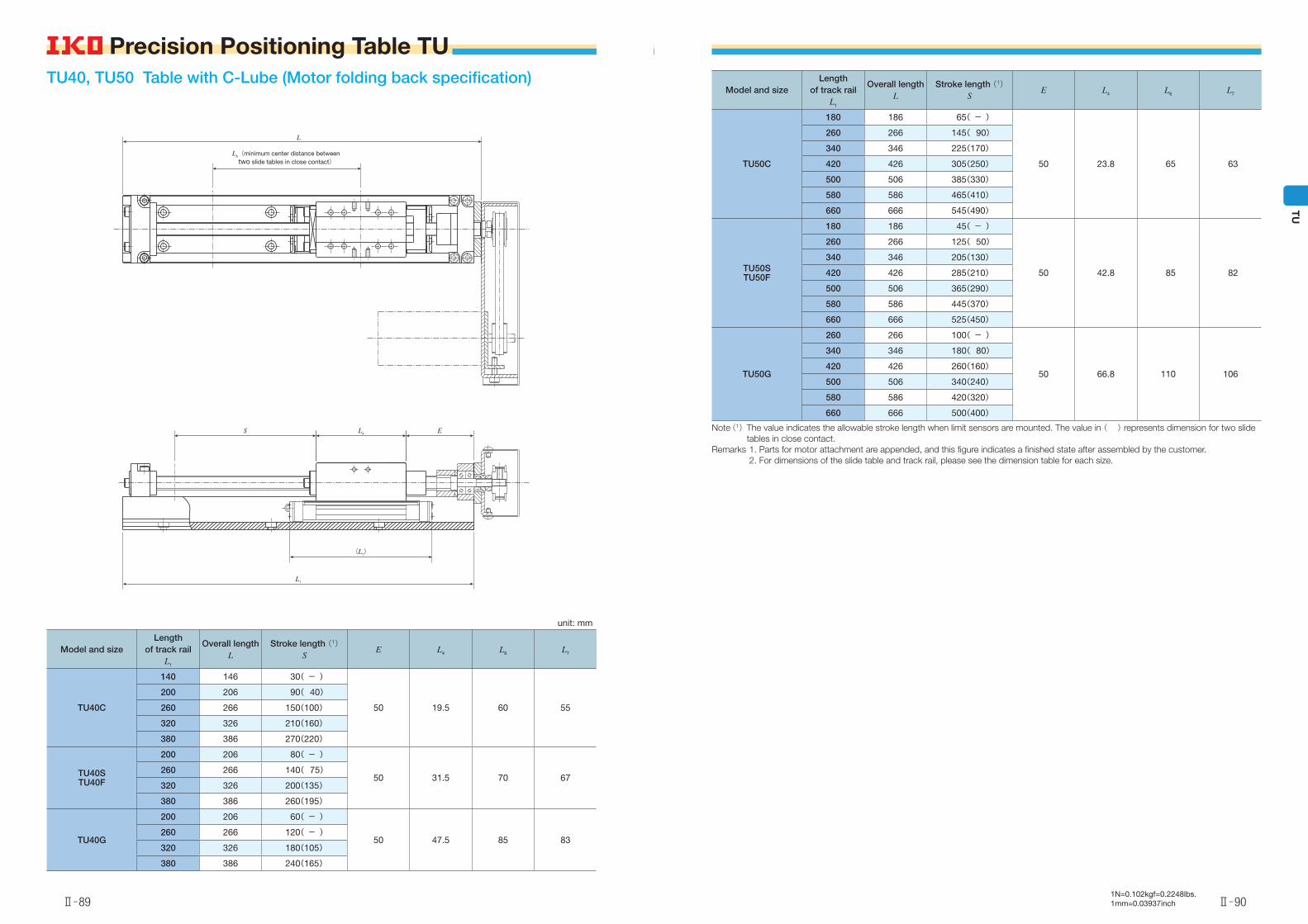
1N=0.102kgf=0.2248lbs.1mm=0.03937inch
Model and sizeLength
of track railL1
Overall lengthL
Stroke length (1)S
E L4 L6 L7
TU50C
180 186 65( - )
50 23.8 65 63
260 266 145( 90)
340 346 225(170)
420 426 305(250)
500 506 385(330)
580 586 465(410)
660 666 545(490)
TU50STU50F
180 186 45( - )
50 42.8 85 82
260 266 125( 50)
340 346 205(130)
420 426 285(210)
500 506 365(290)
580 586 445(370)
660 666 525(450)
TU50G
260 266 100( - )
50 66.8 110 106
340 346 180( 80)
420 426 260(160)
500 506 340(240)
580 586 420(320)
660 666 500(400)
Note (1) The value indicates the allowable stroke length when limit sensors are mounted. The value in ( ) represents dimension for two slide tables in close contact.
Remarks 1. Parts for motor attachment are appended, and this figure indicates a finished state after assembled by the customer. 2. For dimensions of the slide table and track rail, please see the dimension table for each size.
TU40, TU50 Table with C-Lube (Motor folding back specification)
unit: mm
Model and sizeLength
of track railL1
Overall lengthL
Stroke length (1)S
E L4 L6 L7
TU40C
140 146 30( - )
50 19.5 60 55
200 206 90( 40)
260 266 150(100)
320 326 210(160)
380 386 270(220)
TU40STU40F
200 206 80( - )
50 31.5 70 67260 266 140( 75)
320 326 200(135)
380 386 260(195)
TU40G
200 206 60( - )
50 47.5 85 83260 266 120( - )
320 326 180(105)
380 386 240(165)
L6(minimum center distance between two slide tables in close contact)
L
L4 E
(L7)
S
L1
Ⅱ̶89
Precision Positioning Table TU
Ⅱ̶90
TU
Precision Positioning Table TU
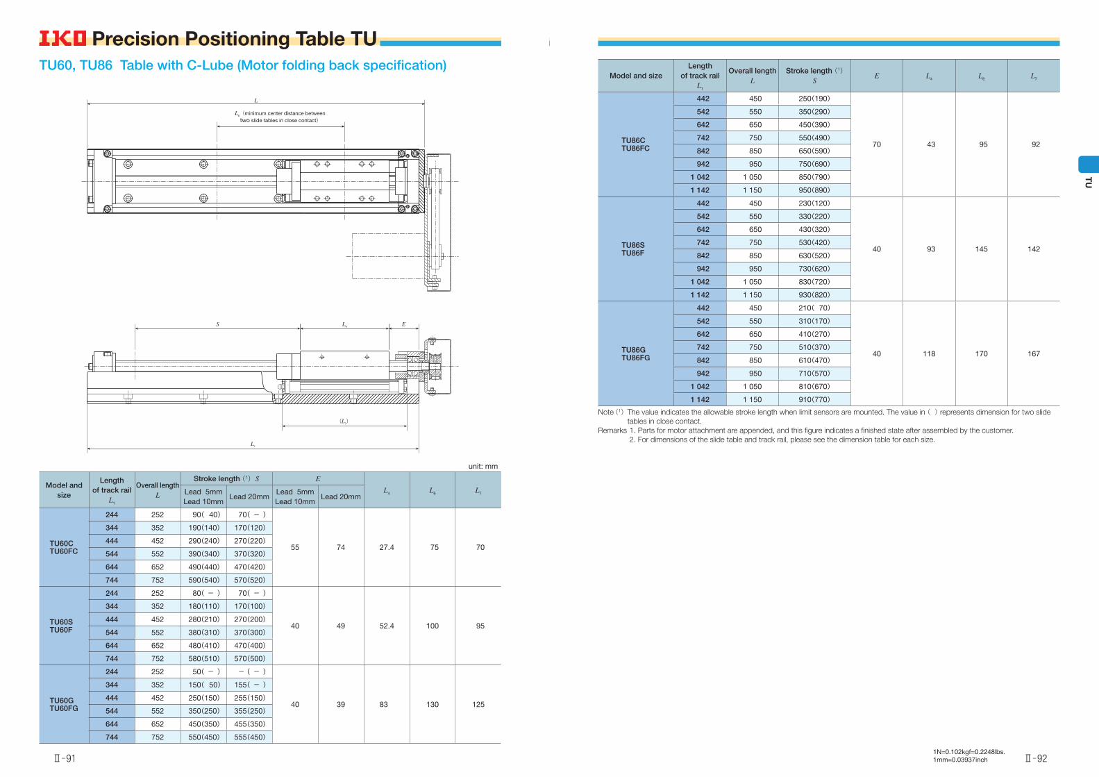
1N=0.102kgf=0.2248lbs.1mm=0.03937inch
Model and sizeLength
of track railL1
Overall lengthL
Stroke length (1)S
E L4 L6 L7
TU86CTU86FC
442 450 250(190)
70 43 95 92
542 550 350(290)
642 650 450(390)
742 750 550(490)
842 850 650(590)
942 950 750(690)
1 042 1 050 850(790)
1 142 1 150 950(890)
TU86STU86F
442 450 230(120)
40 93 145 142
542 550 330(220)
642 650 430(320)
742 750 530(420)
842 850 630(520)
942 950 730(620)
1 042 1 050 830(720)
1 142 1 150 930(820)
TU86GTU86FG
442 450 210( 70)
40 118 170 167
542 550 310(170)
642 650 410(270)
742 750 510(370)
842 850 610(470)
942 950 710(570)
1 042 1 050 810(670)
1 142 1 150 910(770)
Note (1) The value indicates the allowable stroke length when limit sensors are mounted. The value in ( ) represents dimension for two slide tables in close contact.
Remarks 1. Parts for motor attachment are appended, and this figure indicates a finished state after assembled by the customer. 2. For dimensions of the slide table and track rail, please see the dimension table for each size.
TU60, TU86 Table with C-Lube (Motor folding back specification)
unit: mm
Model and size
Length of track rail
L1
Overall lengthL
Stroke length (1) S E
L4 L6 L7Lead 5mmLead 10mm
Lead 20mmLead 5mmLead 10mm
Lead 20mm
TU60CTU60FC
244 252 90( 40) 70( - )
55 74 27.4 75 70
344 352 190(140) 170(120)
444 452 290(240) 270(220)
544 552 390(340) 370(320)
644 652 490(440) 470(420)
744 752 590(540) 570(520)
TU60STU60F
244 252 80( - ) 70( - )
40 49 52.4 100 95
344 352 180(110) 170(100)
444 452 280(210) 270(200)
544 552 380(310) 370(300)
644 652 480(410) 470(400)
744 752 580(510) 570(500)
TU60GTU60FG
244 252 50( - ) -( - )
40 39 83 130 125
344 352 150( 50) 155( - )
444 452 250(150) 255(150)
544 552 350(250) 355(250)
644 652 450(350) 455(350)
744 752 550(450) 555(450)
L6(minimum center distance between two slide tables in close contact)
L
L4 ES
(L7)
L1
Ⅱ̶91
Precision Positioning Table TU
Ⅱ̶92
TU
Precision Positioning Table TU
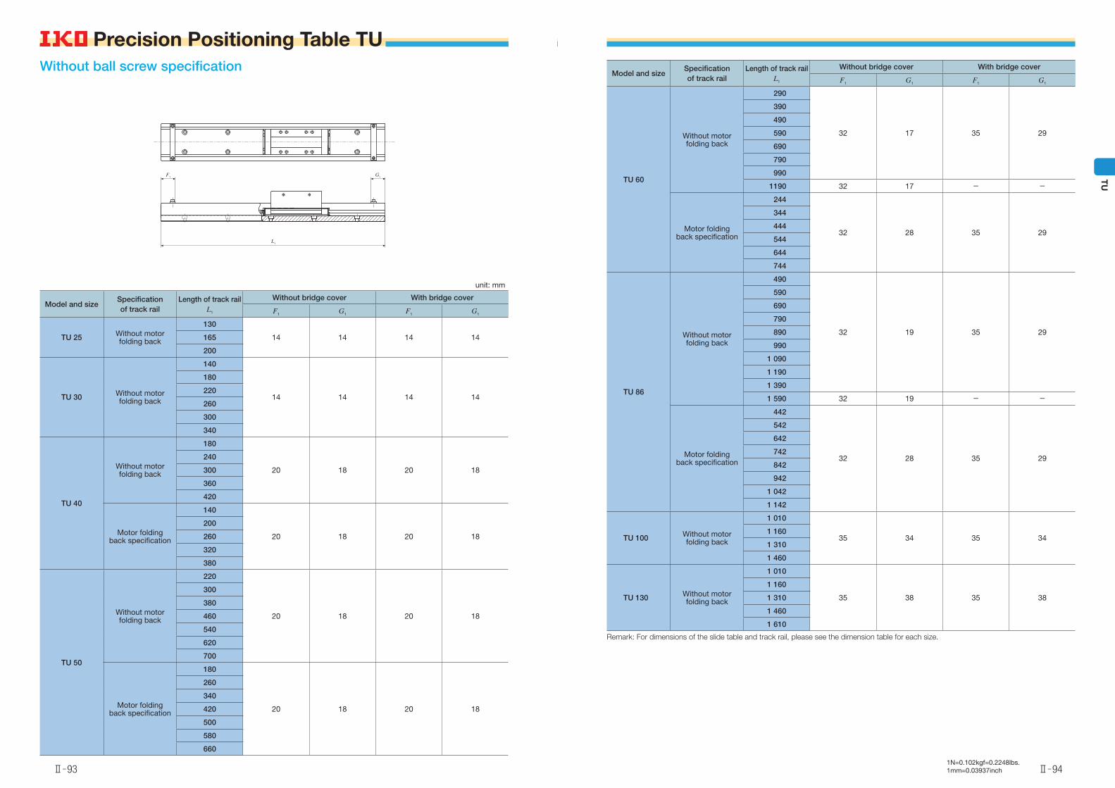
1N=0.102kgf=0.2248lbs.1mm=0.03937inch
Model and sizeSpecification of track rail
Length of track railL1
Without bridge cover With bridge cover
F1 G1 F1 G1
TU 60
Without motor folding back
290
32 17 35 29
390
490
590
690
790
990
1190 32 17 - -
Motor folding back specification
244
32 28 35 29
344
444
544
644
744
TU 86
Without motor folding back
490
32 19 35 29
590
690
790
890
990
1 090
1 190
1 390
1 590 32 19 - -
Motor folding back specification
442
32 28 35 29
542
642
742
842
942
1 042
1 142
TU 100 Without motor folding back
1 010
35 34 35 341 160
1 310
1 460
TU 130 Without motor folding back
1 010
35 38 35 38
1 160
1 310
1 460
1 610
Remark: For dimensions of the slide table and track rail, please see the dimension table for each size.
Without ball screw specification
unit: mm
Model and sizeSpecification of track rail
Length of track railL1
Without bridge cover With bridge cover
F1 G1 F1 G1
TU 25 Without motor folding back
130
14 14 14 14165
200
TU 30 Without motor folding back
140
14 14 14 14
180
220
260
300
340
TU 40
Without motor folding back
180
20 18 20 18
240
300
360
420
Motor folding back specification
140
20 18 20 18
200
260
320
380
TU 50
Without motor folding back
220
20 18 20 18
300
380
460
540
620
700
Motor folding back specification
180
20 18 20 18
260
340
420
500
580
660
F1 G1
L1
Ⅱ̶93
Precision Positioning Table TU
Ⅱ̶94
TU
Precision Positioning Table TU