special specification 7113 temporary water main...
TRANSCRIPT

7113
1 - 45 10-16 OTU
Special Specification 7113
Temporary Water Main and Service Connections
1. DESCRIPTION
Provide, install, connect, test, disinfect, support, restrain, disconnect, and remove a complete temporary water main in accordance with the plans and specifications and in compliance with the Department's Utility Accommodation Policy (UAP)(Title 43, T.A.C., Sections 21.31-21.55). The temporary water main shall be of the sizes, materials and dimensions shown on the plans and shall include all pipe, all joints and connections to new and existing pipes, all valves, fittings, fire hydrants, pipe joint restraint systems, blocking, and incidentals, as may be required to complete the work. The temporary water main will be laid on the ground and anchored and not buried unless otherwise directed by the Engineer.
The abbreviations AWWA, ASA, ASTM, and ANSI, as used in this specification, refer to the following organizations or technical societies:
AWWA – American Water Works Association
ASA – American Standards Association
ASTM – American Society for Testing and Materials
ANSI – American National Standards Institute
NSF – National Science Foundation
Where reference is made to specifications of the above organizations, it is to be construed to mean the latest standard in effect on the date of the proposal.
1.1. References.
1.1.1. ANSI/AWWA:
ANSI/AWWA C651 – Disinfect Water Mains;
ANSI/AWWA C906-15 – Polyethylene (PE) Pressure Ppe and Fittings, 4 In. (100 mm.) Through 63 In. (1600 mm.), for Waterworks;
AWWA M55 – Manual of Water Supply Practices, PE Pipe Design and Installation.
1.1.2. National Sanitation Foundation:
NSF/ANSI 61 – Drinking Water System Components – Health Effects;
NSF/ANSI 14 – Plastic Piping System Components and Related Materials;
1.1.3. American Society of Testing and Materials (ASTM):
ASTM D1784 – Standard Specification for Rigid PVC Compounds and Chlorinated PVC Compounds;
ASTM D2239 – Standard Specification for Polyethylene (PE) Plastic Pipe (SIDR-PR) Based on Controlled Inside Diameter;
ASTM D2241 – Standard Specification for Poly Vinyl Chloride (PVC) Pressure-Rated Pipe (SDR Series);
ASTM D2387 – Standard Test Method for Obtaining Hydrostatic Design Bases for Thermoplastic Pipe Materials or Pressure Design Basis for Thermoplastic Pipe Products;
ASTM D2774 – Standard Specification for Underground Installation of Thermoplastic Pressure Pipe;
ASTM D3035 – Standard Specification for Polyethylene (PE) Pipe (DR-PR) Based on Controlled Outside Diameter;
XXXX
2 - 45 07-16 OTU
ASTM D3139 – Standard Specification for Joints for Plastic Pressure Pipes Using Flexible Elastomeric Seals;
ASTM D3261 – Standard Specification for Butt Heat Fusion Polyethylene (PE) Plastic Fittings for Polyethylene (PE) Plastic Pipe and Tubing;
ASTM D3350 – Standard Specification for Polyethylene Plastic Pipe and Fittings Materials;
ASTM F477 – Standard Specification for Elastomeric Seals (Gaskets) for Joining Plastic Pipe;
ASTM F714 – Standard Specification for Polyethylene (PE) Plastic Pipe (SDR-PR) Based on Outside Diameter;
ASTM F905 – Standard Practice for Qualification of Polyethylene Saddle-Fused Joints;
ASTM F1055 – Standard Specification for Electrofusion Type Polyethylene Fittings for Outside Diameter Controlled Polyethylene Pipe and Tubing;
ASTM F1290 – Standard Practice for Electrofusion Joining Polyolefin Pipe and Fittings;
ASTM F2164 – Standard Practice for Field Leak Testing of Polyethylene (PE) and Crosslinked Polyethylene (PEX) Pressure Piping Systems Using Hydrostatic Pressure;
ASTM F2206 – Standard Specification for Fabricated Fittings of Butt-Fused Polyethylene (PE);
ASTM F2263 – Standard Test Method for Evaluating the Oxidative Resistance of Polyethylene (PE) Pipe to Chlorinated Water;
ASTM F2620 – Standard Practice for Heat Fusion Joining of Polyethylene Pipe and Fittings.
1.1.4. Plastics Pipe Institute (PPI):
PPI Handbook of Polyethylene Pipe;
PPI TR-33 – Generic Butt Fusion Joining Procedure for Field Joining of Polyethylene Pipe;
PPI TR-34 – Disinfection of Newly Constructed Polyethylene Water Mains;
PPI TR-41 – Generic Saddle Fusion Joining Procedure for Polyethylene Gas Piping;
PPI TN-42 – Recommended Minimum Training Guidelines for PE Pipe Butt Fusion Joining Operators for Municipal and Industrial Projects.
1.2. Submittals.
1.2.1. Quality Assurance/Control Submittals
Provide affirmation that the product shopped meets or exceeds the standards set forth in this specification. This shall be in the form of a written document from the manufacturer attesting to the manufacturing process meeting the standards.
Provide manufacturers recommended installation and pipe joining procedures for the products.
Submit product data for pipe including Product manufacturer’s specifications, pipe and fittings materials of construction and dimensions of pipe and fittings.
Submit certification of conformance with NSF 61 by an acceptable certifying organization.
1.3. Delivery, Storage, and Handling.
Handle the pipe in accordance with the manufacturer’s instructions using approved strapping and equipment rated for the loads encountered. Do not use chains, wire rope, fork lifts or other methods or equipment that may gouge or damage the pipe or endanger persons or property. Field storage is to be in compliance with manufacturer’s recommendations.
Any pipe that has gouges, scrapes, or other damage to the pipe that results in a loss of 10% or more of the pipe wall thickness shall be removed and not used. Inspect the pipe for defects before installation and joining. Defective, damaged, or unsound pipe will be rejected.

XXXX
3 - 45 07-16 OTU
2. MATERIALS
The temporary water main shall be Polyvinyl Chloride (PVC) or High-Density Polyethylene (HDPE) pipe with Iron Pipe Size (IPS) outside diamters up to 16”. All materials used in this project are to be new and unused unless otherwise specified on the plans, specifications or the proposal. The Contractor shall submit descriptive information and evidence that the materials and equipment the Contractor proposed for incorporation into the Work are of the kind and quality that meet the material requirements listed herein. The SAWS Material Specifications are part of this specification and are available on the SAWS website at http://www.saws.org/business_center/specs/matspecs/. Contractors may, when appropriate use products that are specified in these specifications however a Submittal is still required that clearly indicates the applicable SAWS Material Specification. The products listed in the SAWS Material Specifications shall not be considered as a pre-approved list and cannot be substituted for items called out on the Drawings or on bid form.
2.1. Ductile-Iron Fittings.
2.1.1. Fittings for HDPE, PVC C-900, or PVC C-905
This section covers ductile-iron fittings 3 inches through 48 inches in size designed and manufactured for use with gray-iron, ductile-iron, HDPE, PVC C-900 or PVC C-905 pipe. Standard, compact and anchor fittings included herein are of the following types of joints: Flanged and Mechanical Joint
Unless otherwise modified or supplemented herein, the latest revision of AWWA Standard C-110 for Gray-Iron and Ductile-Iron Fittings, 3-inch through 48-inch for Water and Other Liquids” and AWWA Standard C-153 for Ductile-Iron Compact Fittings, is to govern the design, manufacture, and testing of all fittings under this specification.
For 3 through 24-inch size range, the pressure rating of all fittings is to be a minimum of 250 psi. The working pressure for all fittings of size greater than 24-inch is to be a minimum of 150 psi, unless a change in pressure rating is directed by purchase documents.
Fittings are to be furnished with the types of end combination specified.
Flanged fittings are to be faced and drilled in accordance with ANSI Specification B 16.1, Class 125.
Anchor fittings are to be furnished in size and type or length as specified.
The exterior of all fittings shall be provided with a petroleum asphaltic coating in accordance with the latest revision of AWWA Standard C110. The interior of flanged fittings supplied under this specification shall be either cement-mortar lined in accordance with the latest revision of AWWA Standard C104 or lined with a petroleum asphaltic material in accordance with the latest revision of AWWA Standard as specified. The interior of all other fittings supplied under this specification shall be cement-mortar lined in accordance with the latest revision of AWWA Standard C104.
Where standard ductile iron mechanical joint fittings are coupled to plain-end (square-cut) HDPE pipe, mechanical joint adapters must be used.
2.2. Polyethylene Pipe
All polyethylene pipe shall be made from HDPE material having a material designation code of PE3608 or higher. The material shall meet the requirements of ASTM D3350 and shall have a minimum cell classification of PE345464C. The pipe material shall also meet NSF-61.
The pipe and fittings shall meet the requirements of AWWA C906.
XXXX
4 - 45 07-16 OTU
The polyethylene pipe shall be rated for use at a pressure of 160 psi. Polyethylene pipe for use in a “High Pressure Zone” shall be rated for use at a pressure class of 200 psi. The outside diameter of the pipe shall be based upon the DIPS (Ductile Iron Pipe Size) sizing system.
The high density polyethylene pipe manufacturer shall provde either a certification that stress regression testing has been performed on the specific product, or a stress life curve per ASTM D2837. The stress regression testing shall have been done in accordance with ASTM D2837, and the manufacturer shall provide a product supplying a minimum Hydrostatic Design Basis (HDB), as determined in accordance with ASTM D2837.
The manufacturer’s certificate shall state that the pipe was manufactured from one specific resin in compliance with these specifications. The certificate shall state the specific resin use, its source, and list its compliance to these specifications.
The pipe shall be produced with the nominal physical properties outlined in this specification, and to the dimensions and tolerances specified in ASTM F714.
The pipe service identification color for the exterior shell shall be blue for pipes used as potable water mains. The coloring agent used must be resistance to the effects sunlight and must allow the color to be stable for a period of at least six months in full sunlight.
2.2.1. HDPE Pipe Joints
Butt Fusion: Sections of high density polyethylene pipe should be joined into continuous lengths on the job site above ground. The joining method shall be the butt fusion method and shall be performed in strict accordance with the pipe manufacturer’s recommendations. The butt fusion equipment used in the joining procedures should be capable of meeting all conditions recommended by the pipe manufacturer, including, but not limited to, temperature requirements of 400°F, alignment and 75 psi interfacial fusion pressure.
Saddle Fusion: Saddle fusion shall be done in accordance with ASTM F2620 or PPI TR-41 or the manufacturer’s recommendations and PPI TR-41. Saddle fusion joints shall be mad by qualified fusion technicians. Qualifications of the fusion technician shall be demonstrated by evidence of fusion training within the past year on the equipment to be utilized on this project.
Electrofusion: Electrofusion joining shall be done in accordance with the manufacturer’s recommended procedure. Other sources of electrofusion joining information are ASTM F1290 and PPI TN-34. The process of electrofusion requires an electric source, a transformer, commonly called an electrofusion box that has wire leads, a method to read electronically (by laser) or otherwise input the barcode of the fitting, and a fitting that is compatible with the type of electrofusion box used. The electrofusion box must be capable of reading and storing the input parameters and the fusion results for later download to a record file. Qualification of the fusion technician shall be demonstrated by evidence of electrofusion training within the past year on the equipment to be utilized for this project.
Weld Strength: Fusion joining shall be 100% efficient offering a joint weld strength equal to or greater than the tensile strength of the pipe. Socket fusion and extrusion welding shall not be used.
Trial Fusion: At the beginning of each day, a trial fusion will be performed to verify fusion procedure and equipment settings for the actual jobsite conditions. Allow trial fusions to cool completely before cutting straps and tting by bending the straps until the ends touch. The test specimen dimensions shall conform to ASTM D2657.
2.2.2. HDPE Service Connections
Service connections shall be electrofusion saddles with a brass or stainless steel threaded outlet, sidewall fusion branch saddles, tapping tees, or mechanical saddles.

XXXX
5 - 45 07-16 OTU
2.3. Polyvinyl Chloride Pipe
2.3.1. Polyvinyl Chloride Pipe, 4-inch through 12-inch (C-900)
This section covers 4" through 12" diameter polyvinyl chloride (PVC) pressure pipe made from class 12454A or 12454B compounds as determined by ASTM Standard D1784 and providing for a hydrostatic test basis (HDB) of 4,000 psi. All pipe furnished shall be in conformance with AWWA Standard C900, or latest revision thereof.
Except as noted on the plans or procurement specifications for specific jobs, all C900 PVC pipe shall be Class 150 (DR 18) having a sustained pressure requirement of 500 psi (ASTM D2241) and a minimum burst pressure of 755 psi (ASTM D1599). C900 PVC pipe installed in the SAWS High Pressure Zone shall be class 200 (DR 14) having a sustained pressure requirement of 650 psi (ASTM D1598) and a minimum burst pressure of 985 psi (ASTM D1599). Pipe pressure class shall be written on the pipe and as per most current applicable AWWA standards.
Dimensions and tolerances for each nominal pipe sizes shall be in accordance with Section 2.2, Table 1 of AWWA Standard C900.
Pipe shall be furnished in standard laying lengths of 20 feet (plus or minus one inch) unless otherwise noted. Each pipe shall have an integral bell formed on the pipe end, and be designed to be at least as strong as the pipe wall (ASTM D2472).
An elastomeric gasket shall be designed with a retainer ring, which "locks" the gasket into integral bell groove and shall be installed at the point of manufacturer. Gasket shall be in conformance with ASTM F477.
Each length of pipe furnished shall bear identification markings in conformance with Section 2.6 of AWWA Standard C900.
Pipe shall be bundled in pallets for ease of handling and storage. Pipe bundles (units) shall be packaged to provide structural support to insure that the weight of upper units shall not cause deformation to pipe in lower units. No pipes bundles shall be accepted which show evidence of ultraviolet radiation "sunburn" on exposed pipe as may be caused from extended unprotected storage conditions.
The manufacturer shall take adequate measures during pipe production to assure compliance with AWWA C900 by performing quality-control tests and maintaining results of those tests as outlined in Section 3 of that Standard. Submission of product shall constitute certification of compliance with this standard.
A one-year warranty shall be provided for all materials sold and delivered for use and incorporated into the San Antonio water distribution system. Such warranty shall take effect on the date that the pipe is received and accepted by an authorized representative of the San Antonio Water System.
User references and a claims history shall be provided for further investigation, prior to rending a final decision on the acceptance of the product to be furnished.
The San Antonio Water System may, at no cost to the manufacturer, subject random lengths of pipe to testing by an independent laboratory for compliance with this specification. Any visible defect of failure to meet the quality standards herein will be grounds for rejecting the entire order.
2.3.2. Joint Restraint System
This section covers pipe joint restraint systems to be used on domestic water mains for PVC C-900 pipe sizes 4-inch through 12-inch diameter and PVC C-905 pipe sizes 16-inch through 24-inch diameter. Joint
XXXX
6 - 45 07-16 OTU
restraint systems are classified as “compression, “mechanical joint” or “non-metallic restrained joint” for the specific type of pipe joint to be restrained.
2.3.2.1. General Requirements
Underwriter Laboratories (U.L) and Factory Mutual (FM) certifications are required on all restraint systems.
Unless otherwise noted, restraint systems to be used on PVC C-900 and C-905 pipe shall meet or exceed A.S.T.M. Standard F1674-96, “Standard Test Methods for Joint Restraint Products for Use with PVC Pipe,” or the latest revision thereof. Restraint systems used on ductile pipe shall meet or exceed U.L. Standard 194
Non-metallic restrained joint pipe and couplings shall be utilized specifically for C-900 PVC pipe and fittings in sizes 4-inch-12-inch.
Each restraint system shall be packaged individually and include installation instructions.
2.3.2.2. Specific Requirements.
2.3.2.2.1. Restrainer for PVC C-900/C-905 & Ductile Iron Push-on Type Connections:
Pipe restraints shall be utilized to prevent movement for push-on D.I. or PVC (C-900&C-905) (compression type) bell and spigot pipe connections or where a transition or flexible coupling has been used to join 2 sections of plain-end pipe D.I. or PVC (C-900&C-905). The restrainer may be adapted to connect a plain end D.I. or PVC pipe to a ductile iron mechanical joint (MJ) bell fitting. The restrainer must not be directionally sensitive.
The pipe shall be restrained by a split retainer band. The band shall be cast ductile iron, meeting or exceeding ASTM A-536-80, Grade 65-45-12. The inside face or contact surface of the band shall be of sufficient width to incorporate cast or machined non-directionally sensitive serration to grip the outside circumference of the pipe. The serration shall provide full (360 °) contact and maintain pipe roundness and avoid any localized points of stress. The split band casting shall be designed to “bottom-out” before clamping bolt forces (110ft-lb minimum torque) can over-stress the pipe, but will provide full non-directionally sensitive restraint at the rated pressures.
Bolts and nuts used to attach the split retainer ring shall comply with ANSI B-18.2/18.2.2, SAE Grade 5. Tee-bolts, nuts and restraining rods shall be fabricated from high-strength, low-alloy steel per AWWA C-111-90.
The split ring type non-directionally sensitive restrainer system shall be capable of a test pressure twice the maximum sustained working pressure listed in section D and be for both D.I. and/or PVC C-900.
Restraint systems sizes 6 through 12-inch shall be capable of use for both ductile iron and/or PVC C-900.
The restraint system may consist of 2 types: the two split retainer rings and for new construction use only the 1 split and 1 solid cast backup ring.
2.3.2.2.2. Compression Ring Fitting Restrainer for Ductile Iron Pipe & PVC C-900.
Compression ring with follower gland type of restrainer may be utilized in conjunction with Mechanical Joint (MJ) bell end ductile iron pipe fittings for restraining PVC C-900 and ductile iron pipe.
The system shall utilize a standard MJ gasket with a color-coded compression ring and replacement gland conforming to ASTM A-536-80, Grade 65-45-12.
XXXX
7 - 45 07-16 OTU
Standard MJ fitting Tee-bolts and nuts shall be fabricated from high strength steel conforming to ANSI AWWA C-111/A-21.11 and AWWA C-153/A-21.53-88.
Standard MJ gasket shall be virgin SBR meeting ASTM D-2000 3 BA 715 or 3 BA 515.
The restraint system shall be capable of a test pressure twice the maximum sustained working pressure listed in section D.
2.3.2.2.3. Non-metallic restrained joint pipe and couplings for PVC C-900 Type Connections:
Gasketed restrained coupling connections shall join two sections of factory grooved PVC (C-900) pipe. The restrainer coupling or must not be directionally sensitive.
The coupling shall incorporate twin elastomeric sealing gaskets meeting the requirements of ASTM F-477 and shall be DR-14 Class 200 C-900 PVC in all applications, meeting or exceeding the performance requirements of AWWA C-900, latest revision. The inside face or contact surface of the coupling connection shall be of sufficient width to incorporate a factory machined non-directionally sensitive groove in both pipe and coupling to grip the outside circumference of the pipe. The couplings shall provide full (360 °) contact and maintain pipe roundness and avoid and localized points of stress. The coupling shall be designed with an internal stop to align the precision-machined grooves in the coupling and pipe prior to installation of a non-metallic thermoplastic restraint spleen, and will provide full non-directionally sensitive restraint at the rated pressures.
High-strength flexible thermoplastic spleens shall be inserted into mating precision–machined grooves in the pipe and coupling to provide full non-directional restraint with evenly distributed loading.
The non-metallic restrained joint pipe and couplings for PVC C-900 type non-directionally sensitive restrainer system shall be capable of a test pressure twice the maximum sustained working pressure listed in Section D and be for PVC (C-900) pipe sizes 4 through 12-inch.
Non-metallic restrained joint pipe and couplings for PVC C-900 restrained systems sizes 4 through 12-inch shall be capable of use for both Class 150 (DR 18) and 4 through 8-inch for Class 200 (DR 14) PVC C-900 pipe.
The non- metallic restrained joint pipe and couplings for PVC C-900 restraint system shall consist of a pipe and couplings system produced by the same manufacturer meeting the performance qualifications of Factory Mutual (FM) and Underwriters Lab (UL).
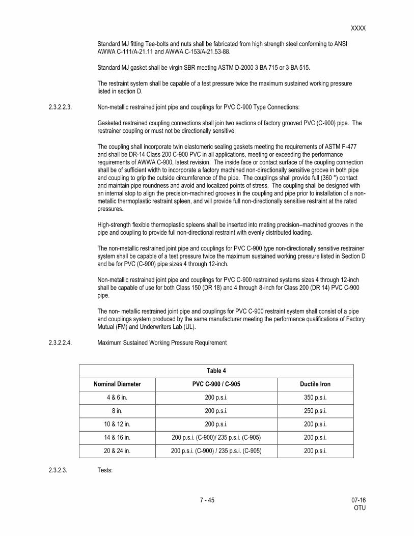
2.3.2.2.4. Maximum Sustained Working Pressure Requirement
Table 4
Nominal Diameter PVC C-900 / C-905 Ductile Iron
4 & 6 in. 200 p.s.i. 350 p.s.i.
8 in. 200 p.s.i. 250 p.s.i.
10 & 12 in. 200 p.s.i. 200 p.s.i.
14 & 16 in. 200 p.s.i. (C-900)/ 235 p.s.i. (C-905) 200 p.s.i.
20 & 24 in. 200 p.s.i. (C-900) / 235 p.s.i. (C-905) 200 p.s.i.
2.3.2.3. Tests:
XXXX
8 - 45 07-16 OTU
The San Antonio Water System may, at no cost to the Contractor, subject random joint restraint system products to testing by an independent laboratory for compliance with these standards. Any visible defect of failure to meet the quality standards herein will be ground for rejecting the entire order.
2.4. Copper Tubing and Brass Fittings for Copper Service Lines.
2.4.1. Copper Tubing.
This section covers copper tubing in nominal sizes of 3/4", 1", 1-1/2" and 2”.
2.4.1.1. General Requirements
Copper service tubing shall be annealed seamless Type "K" and meet ASTM B-88 bearing NSF Standard 61 approval and be rated at 150 psi working pressure..
3/4" and 1" copper tubing shall be furnished in sixty-foot coils or one hundred- foot coil as specified; 1-1/2" shall be furnished in twenty-foot lengths, forty-foot coils or sixty-foot coils as specified, and 2" shall be furnished in twenty-foot lengths or forty foot coils as specified.
Copper tubing is the only allowable material for small service lines.
2.4.2. Brass Fittings.
This section covers waterworks brass goods, such as, corporation stops, curb stops, couplings, connectors, nipples, etc.
2.4.2.1. General Requirements
The brass composition shall conform to ASTM Specifications B-62, or latest revision thereof, fittings shall conform to ANSI/AWWA Specifications C-800, or latest revision thereof.
All brass components in contact with potable water must be “lead free” and marked by stamping, etching or casting “NL” in the main body made from either CDA/UNS Brass Alloys C89520 in accordance with ASTM B584; or C89833. Brass saddles shall be made from CDA/UNS C83600.
Any brass component not in contact with potable water shall be made of 85-5-5-5 brass as defined per ASTM B62, ASTM B584 and AWWA C-800.
All service fittings shall be certified as suitable for contact with drinking water by an ANSI accredited organization in accordance with ANSI/NSF standard 61, Drinking Water Systems Components-Health effects section 8. Proof of certification is required. The lead content of the wetted components in contact with potable water shall also be verified by an ANSI accredited testing facility.
All brass fittings and valves shall have the manufacturers name and/or trademark integrally stamped, or cast into it indicating that the product is manufactured from the low-lead alloy as specified. Another marking such as “NL”, “EBII”,”FD” or other commonly accepted identifier, indicating the alloy as “No-lead”; shall also be cast or stamped into the fitting or valve.
Painting, printing, sticker, or decals attesting to the components “no-lead” certification shall not be permitted.
All casting shall have a natural, clean uniform and smooth surface, and be free from internal porosity.

XXXX
9 - 45 07-16 OTU
All machining shall be done in a workmanlike manner and within the acceptable tolerances.
2.4.2.2. Design Criteria for Ball Type Curb Stops/Angle Valves
All Curb Stop, Corporation and Angle valves shall be ball valves. "Inverted/Ground Key,” type angle valves will not be accepted.
Ball type valves will not have a stop.
All ball valves, couplings and adapters will be pressure rated to 300 psi, and will be supplied with blowout proof stainless steel stems with double SBR, NBR or EPDM O-ring steam seal.
Stem and cap assembly will be two-piece design and will withstand minimum 200 ftp of torque.
Ball seats will be made with unfilled Teflon or EPDM for resilience and minimal friction.
Ball will be lead free cast brass or stainless design. Coated ball is not permitted.
All fittings shall have a lifetime guarantee against lead leachate from the casting.
The reduced port design not will be acceptable.
Pack Joints will not be accepted.
2.5. Gate Valves, Tapping Valves and Tapping Sleeves.
2.5.1. Resilient-Seated Gate and Tapping Valves ANSI/AWWA C509-01
This product specification covers resilient seated gate valves, with nominal diameters of 3 in., 4 in., 6 in., 8 in., 10 in., 12 in., 16 in., and 20 in. Sizes refer to the nominal diameter, in inches, of the waterway through the inlet and outlet connections and the closure area. All products furnished shall conform to the American National Standards Institute and American Water Works Association C509.
2.5.1.1. Definitions
All definitions are defined according to ANSI/AWWA C509-01:
Cosmetic Defect: A blemish, which has no effect on the ability of the component to meet the structural design and production test requirements of this standard. Should the blemish or the activity of plugging, welding, grinding, or repairing of such blemish cause the component to fail these requirements, then the blemish shall be considered a structural defect.
Flanged Joint: The flanged and bolted joint as described in ANSI/AWWA C110/A21.10.
Mechanical Joint: The gasket and bolted joint as described in ANSI/AWWA C111/A21.11.
Push-on Joint: The single rubber gasket joint as described in ANSI/AWWA C111/A21.11.
Structural Defect: A flaw that causes the component to fail the structural design or test requirement of this standard. This includes, but is not limited to imperfections that result in leakage through the walls of a casting, failure to meet the minimum wall-thickness requirement, or failure to meet production tests.
Tapping Valve: A special gate valve designed with end connections and an unobstructed waterway to provide proper alignment and positioning of a tapping sleeve, valve, and machine for tapping pipe dry or under pressure as described in AWWA C509 Section 1.2 Definitions and MSS SP-60.

XXXX
10 - 45 07-16 OTU
2.5.1.2. General Requirements
Except as otherwise modified or supplemented herein, AWWA Standard C-509-01 or the latest revision thereof, shall govern the design, component materials, construction; manufacture and testing of all resilient seated gate valves. Valves shall be suitable for frequent operation as well as service involving long periods of inactivity. Valves shall be NSF-61 certified.
The San Antonio Water System reserves the right to limit the purchase of resilient seat gate valves from manufacturers and to the models specified, as shown in Table 15, provided such resilient seat gate valves conform to the provision contained herein.
The minimum design working water pressure for gate valves with nominal diameters of 3 in., 4 in., 6 in., 8 in., 10 in., and 12 in. shall be 200 psig unless otherwise specified.
The minimum design working water pressure for gate valves with nominal diameters of 16 in., and 20 in. shall be 150 psig unless otherwise specified.
Valves shall be resilient-seated types, bronze mounted with non-rising stems. The closure member shall be fully encapsulated by an elastomer without thin spots or voids. When open the valve shall have a clear, full-port, unobstructed waterway.
Gray iron, ductile iron, steel, brass and bronze materials shall meet or exceed the material requirements of Section 2: Materials of AWWA C-509-01.
Gaskets, O-rings, Coatings, and elastomers shall meet or exceed the material requirements of Section 2: Materials of AWWA C-509-01.
The gate valves shall be designed and constructed for installation in either a horizontal or vertical position. Valves shall be designed for buried installation with stem in the vertical position and shall be furnished for mounting in a horizontal pipeline, unless otherwise specified.
Valve components of brass or bronze shall be manufactured to ASTM recognized alloy specifications of low zinc content bronze, as shown in Table 1 of Section 2.2.4. of ANSI/AWWA Standard C-509-01 or the latest revision thereof. Materials for the stem have minimum yield strength of 40,000 psi. A minimum elongation in 2 inches of 12% and shall be made of bronze per ASTM B763, alloy number UNS C99500. A maximum zinc content of 2% as shown in Table 2 Chemical Requirements of ASTM B763-96 or the latest revision thereof. Stem nut material shall be ASTM B-62 UNS C83600 or ASTM B-584 UNS C84400. The stem shall have a visible external marking at the top to indicate low-zinc, high strength material. The marking shall include a red plastic or neoprene washer placed around the top of the stem under the operating nut.
Valve ends shall be either flanged, tapping valve, mechanical joint, push-on joint or any combination thereof, as specified. All mechanical joint valves shall be supplied with glands, bolts, and gaskets. Valve body bolts and nuts shall meet the strength requirements of ASTM A-307 with dimensions conforming to ANSI B18.2.1. The size of the bolt head shall be equal to the size of the nut and shall be stainless steel in accordance with ASTM 276.
All gate valves shall open right (clockwise), unless otherwise specified.
The following parts of the valve shall be made of either gray or ductile iron: bonnet, body, yoke, wrench nut, O-ring packing plate or seal plate, and gland follower. The gate may be made of gray or ductile iron.
If glands and bushings are used for NRS valves they shall be made of ASTM B-763 bronze UNS C99500. The stem shall be made of cast, forged, or rolled ASTM B-763 bronze UNS C99500. The stem nut material shall be ASTM B-62 bronze UNS C83600 or ASTM B-584 bronze UNS C84400. The gate may be made of bronze ASTM B-763 bronze UNS C99500. Stem seals shall be “O” ring type. The seals shall be designed for dynamic applications.
XXXX
11 - 45 07-16 OTU
The design shall be such that the seal above the stem collar can be replaced with the valve under full pressure in the fully open position. Materials for the “O” ring packing plate shall be in accordance with Section 4.8.3 of the ANSI/AWWA C509-01 Standard or the latest revision thereof.
Enclosed and buried valves shall be coated inside and outside with a fusion bonded epoxy having a nominal 8 mils dry film thickness, which meets or exceeds AWWA C-550-01 and to the maximum extent possible shall be free of holidays. All coatings in contact with the potable water shall be approved for potable water immersion service per ANSI/NSF Standard 61.
The bidder shall submit with his proposal three sets of certified drawings showing the principal dimensions, general construction and material specification of the valve proposed. The number of turns to open (close) shall be clearly noted in the valve information submitted with the proposal documents. The number of turns to open or close the valve shall be consistent for each valve size for each approved manufacturer.
Valves furnished under this specification shall be supplied from the San Antonio Water System approved manufacturer list. To be included on the qualified product list, the manufacturer shall provide an Affidavit of Compliance in accordance with the Section 1.5 of the ANSI/AWWA C-509-01 Standard or latest revision thereof, to include compliance with San Antonio Water System Specification No. 21-02. Records of all tests performed in accordance with Section 6.1 and Section 6.2 of the ANSI/AWWA C-509-01 Standard or latest revision thereof will be made available or provided. These records will be representative test results for Section 6.1 and certificate of testing for Section 6.2. An affidavit of testing for the valve assembly as outlined in Section 6.2.2 of the ANSI/AWWA C-509-01 Standard, (350 ft-lbs) will also be provided. A copy of the manufacturer’s Quality Assurance Program will be submitted. Blueprints and parts list for the valve shall also be provided.
All gate valve parts shall be designed to withstand the following two pressure requirements, without being structurally damaged. (1) An internal test pressure of twice the rated design working pressure of the valve. (2) The full rated internal working pressure when the closure member is cycled once from a fully open to a fully closed position against the full rated unbalanced working water pressure. In addition to these pressure requirements, the valve assembly and mechanism shall be capable of withstanding an input torque as follows: 200 ft.-lbs. for a 3-in. nominal diameter. 200 ft.-lbs. for a 4-in. nominal diameter. 300 ft.-lbs. for a 6-in. nominal diameter. 300 ft.-lbs. for a 8-in. nominal diameter. 300 ft.-lbs. for a 10- in. nominal diameter. And 300 ft.-lbs. for a 12-in. nominal diameter. For sizes larger than a 12 in. nominal diameter refer to the manufacturer’s specifications.
Resilient seats shall be applied to the gate and shall seat against a corrosion resistant surface. The non-metallic seating surface shall be applied in a manner to withstand the action of line fluids and the operation of the sealing gate under long-term service. A metallic surface shall have a corrosion resistance equivalent to or better than bronze. A non-metallic surface shall be in compliance with ANSI/AWWA C-550. The gate must be fully encapsulated by an elastomer without thin spots or voids. Resilient seats shall be bonded. ASTM D-429 either method A or method B shall prove the method used for bonding or vulcanizing. For method A, the minimum strength shall not be less than 250 psi. For method B, the peel strength shall be 75 lb./in.
Flanged Ends: The end flanges of flanged valves shall conform to dimensions and drillings of ANSI/AWWA C-110/A21.10 or ANSI B-16.1, Class 125.
Mechanical Joint Ends: Mechanical joint bell dimensions shall conform to ANSI/AWWA C-111/A21.11.
Push-on Joints: Push-on joints shall conform to the requirements of ANSI/AWWA C-111/A21.11.
The tapping valves shall be mechanical joints with tapping flange on the other end. The tapping valves shall be furnished complete with glands, bolts, and gaskets. The tapping valve shall have a clear unobstructed waterway.

XXXX
12 - 45 07-16 OTU
The seat rings shall be of a large diameter to the permit entry of the full diameter tapping machine cutters. The valve end which mates with the tapping sleeve shall have an alignment lip to fit the recess in the tapping sleeve flange for proper alignment. The lip will be dimensioned in accordance with MSS SP-60 for valves 20-inch nominal pipe size and smaller.
All interchangeable parts shall conform to their required dimensions and shall be free from defects that could prevent proper functioning of the valve. When assembled, valves manufactured in accordance with this standard shall be well fitted and operate smoothly. All like parts of valves of the same model and size produced by the same manufacturer shall be interchangeable.
All castings shall be clean and sound, without defects that will weaken their structure or impair their service. Plugging, welding, or repairing of cosmetic defects is allowed. Repairing of structural defects is not allowed. Repaired valves shall comply with the testing requirements of this specification after repairs have been made. Repairs within the bolt circle of any flange face are not allowed.
All gate valves shall be hydrostatically tested with twice the specified rated pressure applied to one side of the gate and zero pressure applied to the other side. The test is to be made in each direction across the gate. All tests are to be performed at the manufacturer’s plant.
All gate valves shall be operated through a complete cycle in the position for which it was designed to ensure free and proper functioning of all parts in the intended manner. Any defects in workmanship shall be corrected and the test repeated until satisfactory performance is demonstrated. All tests are to be performed at the manufacturer’s plant.
A hydrostatic test pressure equal to twice the rated working pressure of the valve shall be applied to all assembled valves with the gates in the open position. The test shall show no leakage through the metal, pressure containing joints, or stem seals. All tests are to be performed at the manufacturer’s plant.
A test shall be made from each direction at rated working pressure to prove the sealing ability of each valve from both directions of flow. The test shall show no leakage through the metal, pressure containing joints, or past the seat. All tests are to be performed at the manufacturer’s plant.
Markings shall be cast on the bonnet or body of each valve and shall show the manufacturer’s name or mark, the year the valve casting was made, the size of the valve, and the designation of working water pressure, for example “200 W”.
The San Antonio Water System may, at no cost to the Contractor, subject random valves to testing by an independent laboratory for compliance with these standards. Any visible defect or failure to meet the quality standards herein will be grounds for rejecting the entire order and removal from the approval list.
Table 15 identifies specified manufacturers that are approved.
2.5.1.3. Workmanship
All parts of the resilient seat gate valve shall be designed and manufactured to the tolerances specified in ANSI/AWWA C-509-01 or latest revision thereof and this specification.
All parts of the resilient seat gate valve manufactured by a given manufacturer shall be interchangeable with like parts from another resilient seat gate valve of the same model and size and by the same manufacturer.
All interchangeable parts shall conform to their required dimensions and shall be free from defects that could prevent proper functioning of the valve.

XXXX
13 - 45 07-16 OTU
All castings shall be clean and sound, without defects that will weaken their structure or impair their service. Plugging, welding, or repairing of cosmetic defects is allowed. Repairing of structural defects is not allowed. Repaired valves shall comply with the testing requirements of this specification after repairs have been made. Repairs within the bolt circle of any flange face are not allowed.
The resilient seat gate valves shall be well fitted.
Operation of the resilient seat gate valve shall be smooth.
All parts shall be free of structural defects.
The resilient seat gate valve shall be watertight.
2.5.1.4. Painting
All exterior and interior surfaces of the valve shall be coated with epoxy, N.S.F. 61 certified. The epoxy shall have a nominal dry film thickness of 8 mils, and shall be in accordance with AWWA C-550, latest revision.
Coating shall be as close to holiday free as is technologically possible.
2.5.1.5. Testing
Hydrostatic Test: Hydrostatic Test shall be performed on the valve in accordance with Section 6.1 Proof of Design Testing of ANSI/AWWA C-509-01 or latest revision thereof.
Torque Test: Torque Test for prototype valves shall be performed on the valve in accordance with Section 6.1 Proof of Design Testing of ANSI/AWWA C-509-01 or latest revision thereof.
Leakage Test: Leakage Test shall be performed on the valve in accordance with Section 6.1 Proof of Design Testing of ANSI/AWWA C-509-01 or latest revision thereof.
Pressure Test: Pressure Test shall be performed on the valve in accordance with Section 6.1 Proof of Design Testing of ANSI/AWWA C-509-01 or latest revision thereof.
Operation Test: Operation Test shall be performed on the valve in accordance with Section 6.2 Production Testing of ANSI/AWWA C-509-01 or latest revision thereof.
Shell Test: Shell Test shall be performed on the valve in accordance with Section 6.2 Production Testing of ANSI/AWWA C-509-01 or latest revision thereof.
Seat Test: Seat Test shall be performed on the valve in accordance with Section 6.2 Production Testing of ANSI/AWWA C-509-01 or latest revision thereof.
An Affidavit of Compliance certifying that all required tests have been performed shall be provided in accordance with Section 6.3 Affidavit of Compliance of ANSI/AWWA C-509-01.
The Affidavit of Compliance, the results of ASTM testing procedures and requirements for materials, Manufacturer's Quality Assurance Program, and the records of all tests performed on the valve shall be kept and provided by the supplier/manufacturer in a single hard cover bound notebook with the bid or with the shipping documents and shall be approved by the San Antonio Water System.
2.5.1.6. Quality Assurance
Manufacturers shall have an ASME or I.S.O. 9001 registered commercial quality system or is in the process of achieving this certification by June 2001. Noncompliance to this registered commercial quality system requirement by June 2001 will result in removal of the manufacturer's product from Attachment I of this

XXXX
14 - 45 07-16 OTU
specification. If on receipt of resilient seat gate valves they are found to be non-compliant the manufacturer shall replace the defective resilient seat gate valves according to resilient seat gate valve size with a resilient seat gate valve that meets the San Antonio Water System's specifications. The defective resilient seat gate valve will be returned to the manufacturer, freight collect, and the manufacturer shall replace the resilient seat gate valve, freight prepaid.If San Antonio Water System audits, product inspection and performance data review in accordance with these specifications determine excessive resilient seat gate valve non-compliance, the manufacturer will be subject to removal by the Products Standards Committee. If the resilient seat gate valve becomes defective during the manufacturer's specified warranty period a San Antonio Water System quality assurance and manufacturer review will ensue. If the review determines manufacturing non-conformance the manufacturer shall replace the resilient seat gate valve according to size with a resilient seat gate valve that meets the San Antonio Water System's specifications. The defective resilient seat gate valve removed from the field will be returned to the manufacturer, freight collect, and the manufacturer shall replace the resilient seat gate valve, freight prepaid. If the non-conformance product amounts are excessive and result in increased product replacement by San Antonio Water System field staff the manufacturer may be subject to time and material charges.
2.5.1.7. References
American National Standards Institute and American Water Works Association Standard C-509-01 (ANSI/AWWA C-509-01).
Manufacturers Standardization Society MSS SP-60.
2.5.2. Reduced Wall, Resilient Seated Gate and Tapping Valves AWWA C515-01
This product specification covers reduced wall resilient seated gate valves, with nominal diameters of 4 in. through 48 in. Sizes refer to the nominal diameter, in inches, of the waterway through the inlet and outlet connections and the closure area. All products furnished shall conform to the American National Standards Institute and American Water Works Association C515-01 Standard (ANSI/AWWA C515-01) or latest revision thereof and Manufacturers Standardization Society Standard Practice for Connecting Flange Joint Between Tapping Sleeves and Tapping Valves MSS SP-60 or latest revision thereof.
2.5.2.1. Definitions
All definitions are defined according to ANSI/AWWA C515-01.
Cosmetic Defect: A blemish, which has no effect on the ability of the component to meet the structural design and production test requirements of this standard. Should the activity of plugging, welding, grinding, or repairing of such blemish cause the component to fail these requirements, and then the blemish shall be considered a structural defect.
Flanged Joint: The flanged and bolted joint as described inANSI/AWWA C110/A21.10 or ANSI B16.1, Class 125.
Mechanical Joint: The gasketed and bolted joint as described in ANSI/AWWA C110/A21.10, ANSI/AWWA C111/A21.11, or ANSI/AWWA C153/21.53.
Push-on Joint: The single rubber gasket joint as described in ANSI/AWWA C111/A21.11.
Structural Defect: Flaws that cause the component to fail the structural design or test requirements of this standard. This includes, but is not limited to imperfections that result in leakage through the walls of a casting, failure to meet the minimum wall- thickness requirement, or failure to meet production tests.
Tapping Valve: A special gate valve designed with end connections and an unobstructed waterway to provide proper alignment and positioning of a tapping sleeve, valve, and machine for tapping pipe dry or under pressure.

XXXX
15 - 45 07-16 OTU
2.5.2.2. General Requirements
Except as otherwise modified or supplemented herein, ANSI/AWWA Standard C515-01 or the latest revision thereof, shall govern the design, component materials, construction; manufacture and testing of all reduced wall resilient seated gate valves. Valves shall be suitable for frequent operation as well as service involving long periods of inactivity. Valves shall be NSF-61 certified.
The San Antonio Water System reserves the right to limit the purchase of reduced wall resilient seat gate valves from manufacturers and to the models specified, as shown on Attachment I, provided such reduced wall resilient seat gate valves conform to the provision contained herein.
The minimum design working water pressure for gate valves with nominal diameters of 4 in., 6 in., 8 in., 10 in., 12 in., 14 in. and 16 in. shall be 200 psig unless otherwise specified.
The maximum fluid velocity for flow through the valve in full open position shall be 16 ft/s.
Valves shall be reduced wall, resilient-seated types, bronze mounted with non-rising stems. The closure member shall be fully encapsulated by an elastomer without thin spots or voids. When open the valve shall have a clear, full-port, unobstructed waterway.
Gray iron, ductile iron, steel, brass and bronze materials shall meet or exceed the material requirements of Section 4.2: Materials of AWWA C515-01 and the table below.
MATERIAL STANDARD
Gray Iron ASTM A126, Class B
Ductile Iron ASTM A536 no more than .08% phosphorous
Steel SAE Grade 2, ASTM A307, and zinc plated
Bronze ASTM B763 UNS C99500
Bronze Stem Nuts Only ASTM B62 UNS C836000
ASTM B584 UNS C84400
Gaskets, O-rings, Coatings, and elastomers shall meet orexceed the material requirements of Section 4.2 Materials of AWWA C515-01.
The gate valves shall be designed and constructed for installation in either a horizontal or vertical position. Valves designed for buried installation shall have a stem in the vertical position and shall be furnished for mounting in a horizontal pipeline, unless otherwise specified.
Valve components of brass or bronze shall be manufactured to ASTM recognized alloy specifications of low zinc content bronze, as shown in Section 4.2 Materials ANSI/AWWA Standard C515-01 or the latest revision thereof. Material for the stem shall have minimum yield strength of 40,000 psi. A minimum elongation in 2 inches of 12% and shall be made of bronze per ASTM B763, alloy number UNS C99500. A maximum zinc content of 2% as shown in Table 2 Chemical Requirements of ASTM B763-96 or the latest revision thereof. Stem nut material shall comply with the requirements shown above. The stem shall have a visible external marking at the top to indicate low-zinc, high strength material. The marking shall include a red plastic or neoprene washer placed around the top of the stem under the operating nut.
Valve ends shall be either flanged, tapping valve, mechanical joint, push-on joint or any combination thereof, as specified. All mechanical joint valves shall be supplied with glands, bolts, and gaskets. Valve body bolts and nuts shall meet the strength requirements of ASTM A307 with dimensions conforming to ANSI B18.2.1.

XXXX
16 - 45 07-16 OTU
The size of the bolt head shall be equal to the size of the nut and shall be stainless steel in accordance with ASTM 276.
All gate valves shall open right (clockwise), unless otherwise specified.
The following parts of the valve shall be made of ductile iron: bonnet and body. Shell thickness shall meet the minimum thickness requirements of Table 1 Minimum Thickness of Body and Bonnet of Section 4.4 Detailed Design of ANSI/AWWA C515 -01. Valves larger than sixteen-inch shall meet the performance requirements of the San Antonio Water System resilient seat reduced gate valve specification.
If glands and bushings are used for the valves shall be made of ASTM B763 bronze UNS C99500. The stem shall be made of cast, forged, or rolled ASTM B763 bronze UNS C99500. The gate may be made of bronze ASTM B763 UNS C99500. Stem seals shall be “O” ring type. The seals shall be designed for dynamic applications. The design shall be such that the seal above the stem collar can be replaced with the valve under full pressure in the fully open position. Materials for the “O” ring packing plate shall be in accordance with Section 4.4.6 Stem Sealing of the ANSI/AWWA C515-01 Standard or the latest revision thereof.
Enclosed and buried valves shall be coated inside and outside with a fusion bonded epoxy having a nominal 8 mils dry film thickness, which meets or exceeds AWWA C550-01 and to the maximum extent possible shall be free of holidays. All coatings in contact with the potable water shall be approved for potable water immersion service per ANSI/NSF Standard 61.
The bidder shall submit with his proposal three sets of certified drawings showing the principal dimensions, general construction and material specification of the valve proposed. The number of turns to open (close) shall be clearly noted in the valve information submitted with the proposal documents. The number of turns to open or close the valve shall be consistent for each valve size for each approved manufacturer.
Valves furnished under this specification shall be supplied from the San Antonio Water System approved manufacturer list.
All gate valve parts shall be designed to withstand the following two pressure requirements, without being structurally damaged. (1) An internal test pressure of twice the rated design working pressure of the valve. In no case shall the pressure be less than 500 psi without any visual deformation. (2) The full rated internal working pressure when the closure member is cycled once from a fully open to a fully closed position against the full rated unbalanced working water pressure. In addition to these pressure requirements, the valve assembly and mechanism shall be capable of withstanding an input torque as follows: 200 ft.- lbs. for a 4-in. nominal diameter. 300 ft.-lbs. for a 6-in. nominal diameter. 300 ft.-lbs. for an 8-in. nominal diameter. 300 ft.-lbs. for a 10-in. nominal diameter. 300 ft.-lbs. for a 12-in. nominal diameter. 400 ft-lbs. for a 14-inch through 20-inch nominal diameter. 600 ft-lbs. for a 24-inch nominal diameter.
Resilient seats shall be applied to the gate and shall seat againsta corrosion resistant surface. The non-metallic seating surface shall be applied in a manner to withstand the action of line fluids and the operation of the sealing gate under long-term service. A metallic surface shall have a corrosion resistance
equivalent to or better than bronze. A non-metallic surface shall be in compliance with ANSI/AWWA C550. The gate must be fully encapsulated by an elastomer without thin spots or voids. Resilient seats shall be bonded. ASTM D429 either method A or method B shall prove the method used for bonding or vulcanizing. For method A, the minimum strength shall not be less than 250 psi. For method B, the peel strength shall be 75 lb./in.
Flanged Ends: The end flanges of flanged valves shall conform to dimensions and drillings of ANSI/AWWA C110/A21.10 or ANSI B16.1, Class 125.
Mechanical Joint Ends: Mechanical joint bell dimensions shall conform to ANSI/AWWA C111/A21.11.

XXXX
17 - 45 07-16 OTU
Push-on Joints: Push-on joints shall conform to the requirements of ANSI/AWWA C111/A21.11.
Markings shall be cast on the bonnet or body of each valve and shall show the manufacturer’s name or mark, the year the valve casting was made, the size of the valve, the letters "C515", and the designation of working water pressure, for example “200 W”. Markings shall conform to Section 6.1 Marking of ANSI/AWWA C515-01 or latest revision thereof.
The San Antonio Water System may, at no cost to the manufacturer, subject random valves to testing by an independent laboratory for compliance with these standards. Any visible defect or failure to meet the quality standards herein will be grounds for rejecting the entire order and removal of the manufacturer from the attached approval list.
The below qualified product list identifies specified manufacturers that are approved.
The tapping valves shall be configured with a mechanical joint on one end and a tapping flange on the other end. The tapping valves shall be furnished complete with glands, bolts, and gaskets. The tapping valve shall have a clear unobstructed waterway. The seat rings shall be of a large diameter to permit the entry of the full diameter tapping machine cutters. The valve end which mates with the tapping sleeve shall have an alignment lip to fit the recess in the tapping sleeve flange for proper alignment. The lip will be dimensioned in accordance with MSS SP-60 for valves 20-inch nominal pipe size and smaller.
2.5.2.3. Workmanship
All parts of the reduced wall resilient seat gate valve shall be designed and manufactured to the tolerances specified in ANSI/AWWA C515-01 or latest revision thereof and this specification.
All parts of the reduced wall resilient seat gate valve manufactured by a given manufacturer shall be interchangeable with like parts from another reduced wall resilient seat gate valve of the same model and size and by the same manufacturer.
All interchangeable parts shall conform to their required dimensions and shall be free from defects that could prevent proper functioning of the valve.
All castings shall be clean and sound, without defects that will weaken their structure or impair their service. Plugging, welding, or repairing of cosmetic defects is allowed. Repairing of structural defects is not allowed. Repaired valves shall comply with the testing requirements of this specification after repairs have been made. Repairs within the bolt circle of any flange face are not allowed.
The reduced wall resilient seat gate valve shall be well fitted.
Operation of the reduced wall resilient seat gate valve shall be smooth.
All parts shall be free of structural defects.
The reduced wall resilient seat gate valve shall be watertight.
2.5.2.4. Painting
All exterior and interior surfaces of the valve shall be coated with epoxy, N.S.F. 61 certified. The epoxy shall have a nominal dry film thickness of 8 mils, and shall be in accordance with AWWA C550, latest revision.
Coating shall be as close to holiday free as is technologically possible.
2.5.2.5. Testing

XXXX
18 - 45 07-16 OTU
Hydrostatic Gate Test: Hydrostatic Gate Test shall be performed on the valve in accordance with Section 5.1 Testing of ANSI/AWWA C515-01 or latest revision thereof.
Torque Test: Torque Test for prototype valves shall be performed on the valve in accordance with Section 5.1 Testing of ANSI/AWWA C515-01 or latest revision thereof. Prototype valves larger than sixteen-inch shall meet the torque requirements of section 3q above.
Leakage Test: Leakage Test shall be performed on the valve in accordance with Section 5.1 Testing of ANSI/AWWA C515-01 or latest revision thereof.
Hydrostatic Shell Test: Hydrostatic Shell Test shall be performed on the valve in accordance with Section 5.1 Testing of ANSI/AWWA C515-01 or latest revision thereof. Valves larger than sixteen-inch shall be shell tested at twice the rated working pressure but no less than 500 psi.
Production Test: Production Test shall be performed on the valve in accordance with Section 5.1 Testing of ANSI/AWWA C515-01 or latest revision thereof. This same test shall apply to valves larger than sixteen inch.
Operation Test: Operation Test shall be performed on the valve in accordance with Section 5.1 Testing of ANSI/AWWA C515-01 or latest revision thereof.
Seat Test. Seat Test shall be performed on the valve in accordance with Section 5.1 Testing of ANSI/AWWA C515-01 or latest revision thereof.
An Affidavit of Compliance certifying that all required tests have been performed shall be provided in accordance with Section 6.3 Affidavit of Compliance of ANSI/AWWA C515-01.
The Affidavit of Compliance, the results of ASTM testing procedures and requirements for materials, Manufacturer's Quality Assurance Program, and the records of all tests performed on the valve shall be kept and provided by the supplier/manufacturer in a single hard cover bound notebook with the bid or with the shipping documents and shall be approved by the San Antonio Water System.
2.5.2.6. Quality Assurance
Manufacturers shall have an ASME or I.S.O. 9001 registered commercial quality system. If on receipt of reduced wall resilient seated gate valves they are found to be non-compliant the manufacturer shall replace the defective reduced wall resilient seated gate valves according to reduced wall resilient seated gate valve size with a reduced wall resilient seated gate valve that meets the San Antonio Water System's specifications. The defective reduced wall resilient seated gate valve will be returned to the manufacturer, freight collect, and the manufacturer shall replace the reduced wall resilient seated gate valve, freight prepaid. If San Antonio Water System audits, product inspection and data review in accordance with these specifications determine excessive reduced wall resilient seated gate valve non-compliance, the manufacturer will be subject to removal by the Products Standards Committee. If the reduced wall resilient seated gate valve becomes defective during the manufacturer's specified warranty period a San Antonio Water System quality assurance and manufacturer review will ensue. If the review determines manufacturing non- conformance the manufacturer shall replace the reduced wall resilient seated gate valve according to size with a reduced wall resilient seated gate valve that meets the San Antonio Water System's specifications. The defective reduced wall resilient seated gate valve removed from the field will be returned to the manufacturer, freight collect, and the manufacturer shall replace the reduced wall resilient seated gate valve, freight prepaid. If the non- conformance product amounts are excessive and result in increased product replacement by San Antonio Water System field staff the manufacturer may be subject to time and material charges.
2.5.2.7. References
American National standards Institute and American Water Works Association Standard C509-01 (ANSI/AWWA C509 -01). b) Manufacturers Standardization Society MSS SP-60.

XXXX
19 - 45 07-16 OTU
2.5.3. Tapping Valves and Tapping Sleeves
This section covers tapping sleeves installed on pipe from 4” and larger nominal pipe diameter.
2.5.3.1. General Requirements
Band shall conform to the minimum OD size ranges and lengths specified in this specification. The flange shall be manufactured in compliance with AWWA C-223.07, Class D ANSI B.16.1 drilling, recessed for tapping valves MSS_SP60. Mechanical Joint tapping sleeve outlet shall meet or exceed all material specifications as listed below and be suitable for use with Standard mechanical joint x mechanical joint resilient wedge gate valves per ANSI/AWWA C-509-94.
2.5.3.2. Tapping sleeves from 4” through 12” nominal pipe diameter shall meet the following minimum requirements:
Entire fitting to be stainless steel type 304 (18-8). The body, lug and gasket armor plate to be in compliance with ASTM A-240. The flange shall be cast stainless steel in compliance with ASTM A-743. The MJ outlet shall be one-piece casting made of stainless steel. The test plug shall be ¾” NTP in compliance with ANSI B2.1 and shall be lubricated or coated to prevent galling. All metal surfaces shall be passivated after fabrication in compliance with ASTM A-380.
The gasket is to provide a 360-sealing surface of such size and shape to provide an adequate compressive force against the pipe after assembly, to affect a positive seal under combinations of joint and gasket tolerances. The materials used shall be vulcanized natural or synthetic rubber with antioxidants and antioziant ingredients to resist set after installation. No reclaimed rubber shall be used. A heavy-gauge-type 304-stainless armor plate shall be vulcanized into the gasket to span the lug area.
The lugs are to be heliarc welded (GMAW) to the shell. Lug shall have a pass-through-bolt design to avoid alignment problems and allow tightening from either side of the main. Bolts shall not be integrally welded to the sleeve. Finger Lug designs are not approved; it is the intent of these specifications to allow tapping sleeve that has a lug design similar to the approved models.
Bolts and nuts shall be type 304 (18-8) stainless steel and lubricated or Teflon coated to prevent galling or seizing. Bent or damaged unit will be rejected.
Quality control procedures shall be employed to insure that the shell, Lug, (4” and larger nominal pipe diameter) armor plate, gasket and related hardware are manufactured to be free of any visible defects. Each unit, after proper installation, shall have a working pressure rating up to 200 psi, and a test pressure of 250 psi.
The sleeve construction shall provide a positive means of preventing gasket cold flow and/or extrusion.
Each sleeve shall be stenciled, coded or marked in a satisfactory manner to identify the size range. The markings shall be permanent type, water resistant that will not smear or become illegible.
2.6. Valve Boxes
This section covers cast-iron valve box assemblies.
2.6.1. General Requirements:
Each valve box assembly shall be of cast-iron and shall consist of a base, top section, and lid as shown on the plans on San Antonio Water System Standard Drawing No.DA-56-00.
Valve boxes shall be of a single size with a nominal diameter of 6 inches.
XXXX
20 - 45 07-16 OTU
The valve box lid shall be labeled "water" and shall be so designed so that it will remain firmly seated in place when subjected to vehicular traffic.
The valve box assembly shall be of sufficient toughness and strength to withstand impact loads and shock resulting from vehicular traffic.
The valve box assembly shall be coated with a standard bituminous coating of either coal tar or asphalt basic applied to all inside and outside surfaces.
2.7. Standard/Wide Range Ductile Iron Couplings
This section covers ductile iron couplings for use in connection of smooth end joints of cast iron, ductile iron, asbestos cement, steel, PVC or other types of pipe. The couplings must be capable of fitting this variety of pipes with one set of follower flanges or end rings.
2.7.1. General Requirements
Sleeve or center ring shall be nominal O.D. size range and length specified. Sleeve shall be of Ductile Iron ASTM A536. Ends shall have a smooth inside taper to provide uniform gasket seal. Sleeve shall be given a shop coat of oil–modified urethanes, corrosion-resistant paint, or epoxy coating.
Follower flanges or end rings shall be of the thickness determined by the coupling size, and shall be ductile iron, ASTM-536. Flanges shall be identified by a color-coded shop coat finish as described in Item 2a.
Gaskets shall be compression – type, formed with Virgin Styrene Butadiene Rubber (SBR,) ASTM D2000 3 BA715, and compounded with ingredients to produce permanence and resistance to set after installation. O.D. range shall be imprinted/molded on the gasket in permanent ink (Minimum.)
Bolts and Nuts shall be of high-strength, low-alloy steel, with nominal coarse thread, and hex nuts with black finish. Dimensions and minimum stress values shall be in accordance with AWWA/ANSI C111/A21.11.
Where specification states a cast transition or reducing coupling in place of a straight coupling, the sleeve and follower flange shall be of the same manufacturer and compatible for the specific use intended.
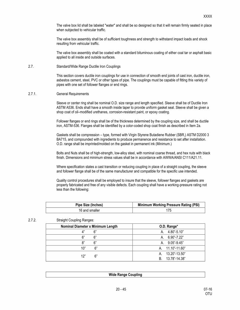
Quality control procedures shall be employed to insure that the sleeve, follower flanges and gaskets are properly fabricated and free of any visible defects. Each coupling shall have a working-pressure rating not less than the following:
Pipe Size (Inches) Minimum Working Pressure Rating (PSI)
16 and smaller 175
2.7.2. Straight Coupling Ranges:
Nominal Diameter x Minimum Length O.D. Range*
4” 6” A. 4.80”-5.10”
6” 6” A. 6.90”-7.22”
8” 6” A. 9.05”-9.45”
10” 6” A. 11.10”-11.60”
12” 6” A. 13.20”-13.50”
B. 13.78”-14.38”
Wide Range Coupling
XXXX
21 - 45 07-16 OTU
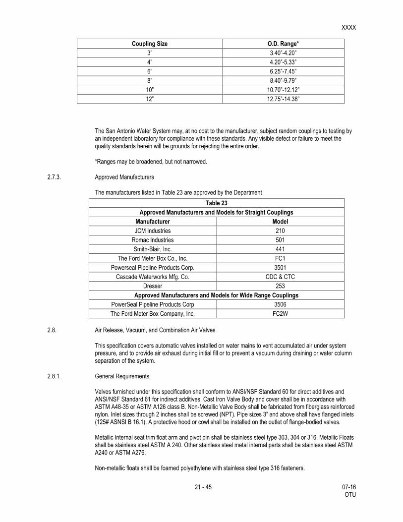
Coupling Size O.D. Range*
3” 3.40”-4.20”
4” 4.20”-5.33”
6” 6.25”-7.45”
8” 8.40”-9.79”
10” 10.70”-12.12”
12” 12.75”-14.38”
The San Antonio Water System may, at no cost to the manufacturer, subject random couplings to testing by an independent laboratory for compliance with these standards. Any visible defect or failure to meet the quality standards herein will be grounds for rejecting the entire order.
*Ranges may be broadened, but not narrowed.
2.7.3. Approved Manufacturers
The manufacturers listed in Table 23 are approved by the Department
Table 23
Approved Manufacturers and Models for Straight Couplings
Manufacturer Model
JCM Industries 210
Romac Industries 501
Smith-Blair, Inc. 441
The Ford Meter Box Co., Inc. FC1
Powerseal Pipeline Products Corp. 3501
Cascade Waterworks Mfg. Co. CDC & CTC
Dresser 253
Approved Manufacturers and Models for Wide Range Couplings
PowerSeal Pipeline Products Corp 3506
The Ford Meter Box Company, Inc. FC2W
2.8. Air Release, Vacuum, and Combination Air Valves
This specification covers automatic valves installed on water mains to vent accumulated air under system pressure, and to provide air exhaust during initial fill or to prevent a vacuum during draining or water column separation of the system.
2.8.1. General Requirements
Valves furnished under this specification shall conform to ANSI/NSF Standard 60 for direct additives and ANSI/NSF Standard 61 for indirect additives. Cast Iron Valve Body and cover shall be in accordance with ASTM A48-35 or ASTM A126 class B. Non-Metallic Valve Body shall be fabricated from fiberglass reinforced nylon. Inlet sizes through 2 inches shall be screwed (NPT). Pipe sizes 3” and above shall have flanged inlets (125# ASNSI B 16.1). A protective hood or cowl shall be installed on the outlet of flange-bodied valves.
Metallic Internal seat trim float arm and pivot pin shall be stainless steel type 303, 304 or 316. Metallic Floats shall be stainless steel ASTM A 240. Other stainless steel metal internal parts shall be stainless steel ASTM A240 or ASTM A276.
Non-metallic floats shall be foamed polyethylene with stainless steel type 316 fasteners.

XXXX
22 - 45 07-16 OTU
Valves requiring Internal seats or orifice buttons shall be Buna-N rubber compounded for water service. For valves requiring cover gaskets, the cover gasket shall be composition type, equal to Armstrong CS-231, Garlock 3000, or Lexide NK-511. If an O-Ring is used to seal the cover, it shall be on NSF 61 certified rubber. Cover bolts shall be alloy steel. Rolling seals shall be furnished for non-metallic valves 2” and below.
Valve body shall have a test pressure rating of 300 psi and working pressure rating of 150 psi.
All components in contact with potable water must be “lead free” and marked by stamping, etching, or casting “NL” in the main body.
2.8.2. General Operation Requirements
The air release valve shall be designed to vent accumulated air automatically. The outlet orifice shall be properly sized to facilitate valve operation at pressures up to 150 psi. The air release valve shall be simple-lever, compound-lever, ball and orifice or rolling seal depending upon volume requirements and the design of the valve.
The air and vacuum valve shall be designed with the inlet and outlet of equal cross-sectional area where applicable. The valve shall be capable or automatically allowing large quantities of air to be exhausted during the filling cycle an also capable of automatically allowing air to re-enter the system to prevent a negative pressure at water column separation or during the draining cycle. The float shall be guided to minimize premature closure by air and to provide proper alignment for normal closure by floating on the water surface.
Combination air and vacuum relief valves shall provide for both automatic air release under system pressure and to allow air movement during filling or draining operations or water column separation. The combination valve may be housed in a single casting. The housing shall be designed to incorporate conventional or kinetic flow principles to properly vent the air without premature closure. Flanged sized (4 inch and larger) may be furnished in a dual housing. When dual casings are used a bronze manual isolation valve shall be installed if indicated by the manufacturer. This will allow the air release valve to be serviced when the system is under pressure. Field service of the valve may also be performed by closing the isolation valve between the air valve and the pipe connection.
2.8.3. Tests
The San Antonio Water System may, at no cost to the manufacturer, subject random valves to testing by an independent laboratory for compliance with these standards. Any visible defect or failures to meet the quality standards herein will be grounds for rejecting the entire order.
2.8.4. Quality Assurance
The manufacturers shall provide certification that products furnished under this specification are manufactured in an ISO 9001 certified facility or documentation from an accredited facility that ISO 9001 certification is in process.
2.9. Blow-off Assemblies and Jumper Connections.
The materials required for both permanent and temporary 2-in. and 4-in. blow-off assemblies and 4-in. jumper connections shall conform to the specifications contained herein and as shown on the plans.
2.10. Backfill
2.10.1. Bedding/Initial Backfilling
The bedding and initial backfill materials for concrete steel cylinder pipe (CSC), ductile iron pipe (DI), HDPE Pipe, Wrapped Steel Pipe, and Polyvinyl Chloride Pipe (PVC) in all nominal diameters shall be composed or
XXXX
23 - 45 07-16 OTU
well graded crushed stone or gravel conforming to the following requirements unless modified by the Engineer.
Modified Grade 5 gravel:
Retained on ½” sieve 0%
Retained on 3/8” sieve 0 – 5 %
Retained on No. 4 sieve 20 - 80%
Retained on No 10 sieve 75 - 100 %
Retained on No 20 sieve 98 - 100%
The quantity and thickness of lifts and compaction of initial backfill materials is to be in accordance with subsection 3.3 of this specification.
Where services ¾” – 2” copper are installed, initial backfill shall be sand conforming to the following requirements: Natural sand or sand produced from crushed gravel or crushed rock maximum ¼-inch; 95 percent shall pass No. 4 sieve, free from clay and organic material, with a maximum 8 percent passing the No. 200 sieve. Larger services utilizing ductile iron pipe or PVC (C-900) pipe shall be backfilled the same as mains. Bedding and Initial Backfill for Water Mains.
Well graded gravels or crushed stone shall meet the requirements of Modified Grade 5 gravel.
2.10.2. Secondary Backfill for Water Mains
Secondary backfill is defined as backfill from 1 foot above the top of the pipe to the top of the trench or bottom of pavement section. Secondary backfill shall be constructed in accordance with details shown in the construction documents.
Secondary backfill shall generally consist of materials removed from the trench and shall be free of brush, debris and trash. Rock or stones having a dimension larger than 6 inches at the largest dimension shall be sifted out and removed before the material is used in the secondary backfilling zone. Secondary backfill material shall be primarily composed of compactible soil materials. The secondary backfill material shall be placed in maximum 12 inch loose lifts or as directed by the Design Engineer and/or Inspector.
2.11. Asphalt.
All asphaltic concrete used in the replacement of pavement over the trench line is to conform to Item 341, “Dense-Graded Hot-Mix Asphalt (QC/QA), Type “C”, except when the use of 6-in. of asphalt treated base is directed., unless otherwise specified on the plans.
2.12. Concrete.
All concrete used as the trench cap and in sidewalks and blocking mains is to conform to Item 421, “Hydraulic Cement Concrete”. Class “A” concrete is to be used in sidewalks and for blocking concrete steel cylinder mains; Class “D” concrete is to be used for the trench cap and for blocking all other types, unless otherwise specified on the plans.
2.13. Reinforcing Steel.
All bar reinforcement is to be Grade 60, conforming to the requirements of Item 440, “Reinforcing Steel”.
2.14. Affidavit of Compliance.

XXXX
24 - 45 07-16 OTU
Unless otherwise directed, the Contractor is to furnish a manufacturer's affidavit of compliance for each of the materials used in this project. The affidavit is to certify that factory inspection and all specified tests have been made and that the material furnished complies with the requirements outlined herein.

XXXX
25 - 45 07-16 OTU
3. CONSTRUCTION METHODS
3.1. Installation
Install temporary water main as shown on the plans. Changes in layout may be made with prior approval of the Engineer. Secure temporary water main with suitable anchoring devices as needed.
Use approved traffic ramps for temporary water main crossings of existing commercial driveways. Cutting and restoring pavement to bury the main at driveway crossings shall only be allowed if approved by the Engineer. Install a valve on the temporary water main at both ends of each driveway crossing.
Ramp and maintain temporary water main at sidewalk crossings.
Make connections to the existing water mains as shown on the plans.
3.2. Excavation
Excavation (trenching) if necessary to complete the temporary water main installation is to be performed in accordance with Item 400, “Excavation and Backfill for Structures”, as outlined herein, as shown on the plans and as directed.
3.2.1. Classification of Excavated Materials
No classification of excavated materials will be made. Excavation and trench work is to include the removal and subsequent handling of all materials excavated in accordance with Item 400, “Excavation and Backfill for Structures”.
3.2.2. Grade of Trench Bottom
The trench is to be over-excavated to a depth of 6-in. below the grade line established for the bottom of the pipe, regardless of the type of pipe. The grade line of the pipe is to then be met by the addition of a layer of approved bedding material as directed.
3.2.3. Unstable Conditions at Grade
Where the bottom of the trench at grade is found to be unstable or to include ashes, cinders, any type of refuse, vegetable or other organic material, or large pieces of fragments or inorganic materials which in the judgment of the Engineer should be removed, the Contractor is to excavate and remove such unsuitable material to the a depth no less than 6-inches below pipe. Before the pipe is laid the grade is to be restored by backfilling with an approved material in layers of 3-in. prior to mechanical compaction to provide stable foundation. The layers are to be slightly moistened and thoroughly compacted so as to provide a uniform and continuous bearing and support for the pipe at every point between bell or collar holes. The finished grade is to be accurately graded to provide uniform bearing and support for each section of pipe at every point along its entire length except for the portions of the pipe sections where it is necessary to excavate for bell holes and for the proper seating of pipe joints.
3.2.4. Trench Excavation Protection
All trench excavation required on this project is to be accomplished as required by the provisions of Item 402, “Trench Excavation Protection”.
3.2.5. Caution in Excavation
The Contractor is to proceed with caution in the excavation and preparation of the trench so that the exact location of underground structures and utilities may be determined whether shown on the plans or not.

XXXX
26 - 45 07-16 OTU
Machine excavation is not permitted closer than 12-in. on either side of other existing underground utilities. The Contractor is to be responsible for the repair of such structures and utilities when broken or damaged. He is also to be responsible for adjusting alignment and trench grades with reference to such structures in order to obtain specified clearance for the water main construction.
Whenever the Engineer determines that it is necessary to explore and excavate to determine the location of existing underground structures and utilities, the Contractor is to make explorations and excavations for such purposes at his expense.
3.2.6. Protection and Restoration of Underground Structures and Facilities
The Contractor is to furnish temporary support, adequate protection, and maintenance of all underground and surface structures, drains, sewers, and other obstructions encountered in the progress of the work. All underground structures and utilities which are disturbed are to be restored by the Contractor at his expense. Materials and methods used for restoration are to be in accordance with current building codes with local amendments, the Department's Utility Accommodation Policy (UAP)(Title 43, T.A.C., Sections 21.31-21.55), and the requirements of the utility agency involved.
3.2.7. Backfill Material Derived from Excavation.
Any excess excavated material, not utilized after all fill requirements have been met, shall become the responsibility of the Contractor. The Contractor shall transport and dispose of it outside the limits of the rights-of-way or easements of this project and of public thoroughfares and water courses, to a permitted fill site in conformity with all applicable City, County, State and Federal codes and ordinances and without liability to SAWS or any individual.
3.2.8. Trench Restoration
The surface of the backfilled trench shall be restored to match the previous existing conditions. This shall include final grading, placement of topsoil and seeding, placement of sod (such as at homes or businesses that had maintained grass), or other unprepared and prepared surfaces.
Trenches in alleys actively being used by vehicles (such as trash pickup, vehicle parking, etc.) shall be restored by grading and compacting to 98% or higher with a minimum of 6 inches of flexbase materials for the entire width of the alley. Asphaltic materials shall have a compaction density of 95%. Alleys not actively used by vehicles shall be graded and compacted to 98% or higher from the top of the initial backfill to the bottom of the pavement section, then spread grass seed for entire width of the alley.
Trenches in paved streets shall be covered with a temporary all weather surface to allow for vehicular traffic until the final asphalt/concrete paving is complete. This surface shall be a minimum of 6 inches compacted and rolled asphaltic black base, either hot-mix or cold-mix applied. It is the Contractor’s responsibility to maintain this surface until the final street restoration is complete. Temporary street striping may also be required. This surface must be removed prior to final asphalting.
All street work shall be done in accordance with the latest TXDOT construction specifications. Included in this requirement is replacement of any curbs or sidewalks damaged or removed during the construction.
No separate payment for the surface restoration is permitted. The cost for this work must be included in the appropriate bid item.
3.2.9. Pavement.
The Contractor is to remove pavement and surfaces as a part of the trench excavation. The removal of pavement and surfaces and their restoration is to be based on the minimum trench widths as specified, plus 6-in. either side or as otherwise provided herein. The Contractor is to use such methods as sawing, drilling, or chipping to assure the breaking of the pavement along straight lines.
XXXX
27 - 45 07-16 OTU
If the Contractor removes or damages pavement or surfaces beyond the limits specified above, such pavement and surfaces are to be restored at the expense of the Contractor.
Where water line construction necessitates cutting through existing streets outside the limits of new street construction, said streets are to be replaced in kind as directed.
Where, in the opinion of the Engineer, it is necessary to maintain traffic across a trench, the Contractor is to install temporary metal bridges as necessary to facilitate the movement of traffic.
The street surface adjacent to the trench is to be kept free of surplus spoil. Construction materials are to be placed at locations that will minimize interference with the traveling public.
3.2.10. Concrete Sidewalks, Driveways, Etc.
All concrete sidewalks, driveways, etc., are to be cut with a concrete saw. When transverse expansion or “dummy” joints are encountered, the concrete is to be removed to the nearest transverse joint on each side of the trench and restored. The depth of cut is to be such that upon removal of the concrete, the sides of the cut are to be straight and square.
Existing reinforcing wire fabric or bars are to be cut and removed to permit completion of trench excavation, pipe laying, and backfill operations. When the backfill operations have been completed, the existing reinforcement is to be replaced in its original position and satisfactorily spliced prior to the replacement of concrete over the new trench alignment.
Transverse “dummy” joints are to be made by a jointing tool or other means acceptable, and are to match in depth and thickness in the existing transverse joints.
Expansion joint material is to be provided where new construction abuts the existing curb or driveway if the Engineer deems it necessary.
Concrete is to be spaded, tamped, and thoroughly compacted until mortar entirely covers the surface and has a monolithic finish. The top surface is to be floated, troweled, and finished to match the existing concrete surface.
Immediately after finishing, the concrete surface is to be protected by a membrane compound curing agent, or by wetted cotton or burlap mats. Either method is to be subject to approval.
3.2.11. Dewatering.
Prevent surface water and subsurface or ground water from flowing into excavations and from flooding project site and surrounding areas.
The contractor shall not allow water to accumulate in excavations or at subgrade level. Remove water to prevent softening of foundation bottoms and soil changes detrimental to stability of subgrades and foundations. Provide and maintain dewatering system components necessary to convey water from excavations.
Convey water removed from excavation and rainwater to collecting or runoff areas away from buildings and other structures. Establish and maintain temporary drainage ditches and other diversion outside excavation limits. Do not use trench excavations as temporary drainage ditches.
Dewatering devices shall be provided by the Contractor with filters to prevent the removal of fines from the soil.
Should the pumping system draw fines from the soil, the Engineer shall order immediate shutdown, and remedial measures will be responsibility of the Contractor.
XXXX
28 - 45 07-16 OTU
Upon completion of the dewatering work, the Contractor shall remove all equipment and leave the construction area in a neat, clean, condition that is acceptable to the Owner.
The Contractor shall maintain ground water table at least 12 inches below the finished excavation subgrade.
Dewatering Performances. Performances of the dewatering system for lowering ground water shall be measured by observation wells on piezometers installed I conjunction with the dewatering system, and these shall be documented at least daily. The Contractor shall maintain a log of these readings and submit them to the Owner.
No direct payment shall be made for costs associated with dewatering. All costs in connection therewith shall be included in the applicable contract price for the item to which the work pertains.
3.3. Pipe Laying
3.3.1. General Requirements
The Contractor is to start his work at a tie-in point, unless otherwise indicated on the plans. Pipe is to be laid with bell ends facing the direction of lying, unless otherwise authorized or directed. Under no circumstances is pipe to be laid in water and no pipe is to be laid under unsuitable weather or trench conditions. All valves and fire hydrants must be installed as soon as pipe laying reaches their established location. Pipe is to be installed to the required lines and grades with fittings, valves, and hydrants placed at the required locations.
The temporary water main shall be laid on top of the existing ground and anchored, as necessary, unless otherwise directed by the Engineer.
Spigots are to be centered in bells or collars, all valves and hydrant stems are to be set plumb, and fire hydrant nozzles are to face as shown on the plans or as directed. No valve or other control on the existing system is to be operated for any purpose by the Contractor unless a representative of SAWS is present.
The Contractor is to maintain a neat and orderly work area. Complete cleanup is to be maintained at all times as closely behind the pipe laying operations as possible, but in no case is such cleanup be permitted to lag more than 1,000-ft. behind the pipe laying, unless otherwise directed.
The Contractor is to maintain service to water connections, whether connected to the existing or proposed water lines, at all times for the duration of the construction, unless directed otherwise by the Engineer.
3.3.2. Crossing other Underground Lines
The temporary water main crossing other underground utilities are to have a minimum of 30-in. of cover over the top of the pipe unless otherwise waived or modified. Excavation around other utilities is to be done by hand for at least 12-in. all around. Any damage to the protective wrap on gas lines or electrodes is to be reported immediately to CPS Energy, phone (210) 353-3333. Any damage to other utilities shall be reported to their proper governing entity.
3.3.3. Pipe Grade
The temporary water main, if required to be buried, shall have a minimum of 30 inches of cover from the existing ground/street elevation.
3.3.4. Bedding and Bedding Materials
Prior to placing pipe in a trench, the trench is to have been excavated to the proper depth as required in Subarticle 3.2, “Excavation”. Approved imported materials or Engineer-approved materials selected from suitable fines derived from the excavation shall be smoothly worked across the entire width of the trench bottom to provide a supporting cushion.

XXXX
29 - 45 07-16 OTU
3.3.5. Structures to Support Pipe:
3.3.6. At locations where the bottom of a trench at subgrade consists of material that is notably unstable and conditions are such that the existing material cannot be reworked to make it stable then the trench subgrade shall be overexcavated, filled with approved material and properly compacted in place to provide a suitable base to support the pipe. If it is determined by the Engineer that this method cannot be used to stabilize the trench subgrade then and cannot be removed and replaced with approved material may be properly compacted in place to support the pipe. The Contractor shall also construct a foundation for the pipe consisting of piling, concrete beams, or other supports in accordance with plans prepared by the Engineer. Extra compensation will be allowed for the Contractor for the additional work done. Coordinate with Engineer for approval of extra compensation prior to beginning work.Lowering Materials into Trench
Proper implements, tools and facilities satisfactory to the Engineer are to be approved and used by the Contractor for the safe and convenient execution of work. All pipe, fittings, valves, and hydrants are to be carefully lowered into the trench piece by piece by means of a derrick, ropes, or other suitable tools or equipment in such a manner as to prevent damage to water main materials and protective coatings and lining. Under no circumstances are water main materials to be dropped or dumped into the trench. Take care to avoid damaging polywrap films. Use of chains or slings is not allowed unless entire sling is wrapped with a protective nylon web sock.
3.3.7. Installing Pipe
Every precaution is to be taken to prevent foreign material from entering the pipe while it is being placed in the line. Under adverse trench conditions, extended period of time and/or otherwise required by the Engineer, a manufactured cap/plug is to be used to prevent any foreign type material entering. Leave the cap/plug in place until a connection is made to the adjacent pipe. Inspect the interior of each pipe for defects and reject if defects are found.
After placing a length of pipe in on the ground or in the trench, the jointed end is to be centered on the pipe already in place, forced into place, brought to correct line and grade, completed in accordance with the requirements specified herein. For pipe installed in a trench, the pipe shall be installed in a continuous bedding envelope which shall extend the full trench width to a depth of at least 6 inches below the pipe and to a depth at least 12 inch above water pipe. The pipe is to be secured in place with approved bedding placed in lifts not exceeding 8 inches loose thickness and compacted thoroughly to provide uniform support for the pipe barrel and to fill all voids around the pipe . Pipe and fittings which do not allow a sufficient and uniform space for joints will be rejected and are to be replaced with pipe and fittings of proper dimensions. Precautions are to be taken to prevent dirt or other foreign matter from entering the joint space.
At times when pipe laying is not in progress the open end of pipe is to be closed by a watertight plug or other means approved. Pipe which cannot temporarily be jointed is to be capped or plugged at each end to make it watertight. This provision is to apply during all periods when pipe laying is not in progress. Should water enter the trench, the seal is to remain in place until the trench is completely dry. The Contractor is to provide plug & caps of various sizes required.
3.3.7.1. PVC (C-900 and C-905)
Lay PVC mains to the depths and grades shown on plans. Lay pipe by inserting spigot end into bell flush with insertion line or as recommended by manufacturer. At no time is bell end allowed to go past “insertion line”. A gap between end of spigot and adjoining pipe is necessary to allow for expansion and contraction.
3.3.7.2. Polyethylene Pipe
Lay HDPE mains to the depths and grades shown in the plans and in accordance with AWWA Manual of Practice M55 Chapter 7 and shall be Stand recommended by manufacturer.
XXXX
30 - 45 07-16 OTU
3.3.8. Defective or Damaged Material
Pipe and accessories are to be inspected for defects prior to being lowered into the trench. Any pipe section, fitting, or special which shows dents, kinks, abrupt changes of curvature other than specified, or any other damage will be rejected. Any pipe section, fittings, or special section that has been dropped from a truck or crane will be rejected. The Contractor shall, at his expense, replace or recondition each rejected section. Reconditioning procedures must be acceptable to the Engineer. Any defective, damaged, or unsound material is to be repaired or replaced as directed.
Should a damaged piece of pipe furnished by the Contractor be placed in the water main, the Contractor is to furnish, at his expense, all labor and materials required for removing and replacing the defective pipe and restoring the street to its condition just prior to the failure of the pipe. Should the Contractor damage the pipe after installation, the Engineer may permit the damaged section to be cut from the length unless it is the opinion of the Engineer that the entire length was damaged. The cost and replacement of broken pipe is to be at the expense of the Contractor.
3.3.9. Holes at Bells and Collars.
Bell holes of sufficient size are to be provided at each joint to permit the joints to be made properly. For mechanical type joints the minimum clearance between the bell and natural ground is to be 6-in. in all directions. Bell holes for concrete steel cylinder pipe are to be of sufficient size to properly joint the pipe and place the required grout. Subject to the above provisions the length of excavation for bell holes below grade of the trench bottom is to be kept to a minimum.
3.3.10. Deviations in Line or Grade.
Wherever obstructions, not shown on the plans, are encountered during the progress of the work and such obstructions interfere to such an extent that an alteration on the plan is required, the Engineer is to have the authority to change the plans and direct a deviation from the line and grade or to arrange with the owners of the structures for the removal, relocation, or reconstruction of the obstruction. Any deviation from the line is to be accomplished by the use of appropriate bends unless such requirements are specifically waived by the construction inspector.
3.3.11. Cutting Pipe.
The cutting of pipe for inserting valves, fittings or closure pieces is to be accomplished so as to produce a smooth end at right angles to the axis of the pipe. Strictly follow the recommendations of the pipe manufacturer. Under no circumstances is a workman not equipped with proper safety goggles and helmet and other required safety attire permitted to engage in this work.
3.3.12. Protective Coating and Wrapping on Joints.
All bolts and nuts installed for underground service on valves, fire hydrants, cast-iron mechanical joint fittings, pipe joints, and other ferrous metal appurtenances are to be packed in an approved protective coating material after installation. After the joint has been made and bolts drawn to proper tension, the joint including glands, flanges, bolt heads, and nuts are to be covered with an approved coating. Such protective coating is supplemental to anti-corrosive sand embedment. Asphaltic coatings such as Talcote is not allowed. Coating and wrapping of joints is to be considered subsidiary to the installation and will not be paid for directly.
Steel Pipe Field Welded Joints: After installation of pipe, bends and specials, all end of pipe adjacent to welded field joints, including the weld proper, shall be cleaned, primed, painted or wrapped as specified for the pipe adjacent to the weld.

XXXX
31 - 45 07-16 OTU
3.3.13. Joint Assembly.
Rubber Ring Joints: The installation of pipe and the assembly of rubber ring joints for ductile-iron pipe, concrete-steel cylinder pipe and asbestos cement pipe, is to conform to the pipe manufacturer's assembly instructions. The method of inserting spigot ends of pipe in bells or collars known as “stabbing” is not permitted with pipe larger than 6-in.in size. Spigot ends of pipe larger than 6-in. in size must be properly inserted in the joint by means of suitable pushing or pulling devices.
Mechanical Couplings: The installation of mechanical couplings is to be assembled and installed according to the standards recommended by the manufacturer. Prior to the installation of the mechanical coupling, the pipe ends are to be cleaned by wire brush or other acceptable method to provide a smooth bearing surface for the rubber compression gasket. The pipe is to be marked to align the end of the coupling which will center it over the joint. After positioning, the nuts are to be drawn up finger tight. Uniform pressure on the gaskets is to be applied by tightening alternate bolts on the opposite side of the circle in incremental amounts. Final tensioning is to be accomplished with a torque wrench and in a manner similar to the tightening procedure. The coupling is to then be left undisturbed for 24 hours to allow the gaskets to “pack-in”. Final torque check is to then be made prior to coating and wrapping the joint. Table 21, Torque for Mechanical Couplings, sets forth the proper torque for various sized mechanical couplings and is included for the convenience of the Contractor.
Restrained Joints: Install restraint joints as shown on plans or as directed by Engineer. Install in accordance with manufacturer’s recommendations.
Table 26
Torque for Mechanical Couplings
Coupling Size Bolt Diameter Torque
2” to 24” 5/8” 75 ft/lb
2” to 24” 3/4” 90 ft/lb
30” and 36” (1/4”x7” Middle Rings) 5/8” 65 ft/lb
30” thru 36” (3/8” & heavier Middle Rings)
5/8” 70 ft/lb
30” to 48” 3/4” 80 ft/lb
48” to 72” 3/4” 70 ft/lb
3.3.14. Gray Iron and Ductile Iron Fittings
Fittings: Fittings 6-in. through 12-in. in size are to be either mechanical joint, push-on joint short body, or push-on joint compact body unless otherwise stated on the plans. Fittings shall be installed with the thrust blocking or joint restraint shown in standard drawing DD-839 series. Fittings 16-in. through 24-in. in size are to be mechanical joint type unless otherwise specified on the plans. Adaptors are to be used where necessary to provide a transition between asbestos-cement pipe and the fittings. Restraint or thrust blocking is to be provided as specified on the plans or as directed. Anti-corrosion embedment incidental to all installed cast-iron fittings shall be provided as specified in and no separate payment will be made for this embedment.
Cleaning Ductile Iron: All lumps, blisters, and excess coal-tar coating is to be removed from the ends of ductile-iron pipe fittings. The outside of the spigot and the inside of the bell is to be wire-brushed and wiped clean, dry, and free from oil and grease before the pipe is laid. The interior of the pipe is to be blown clean with compressed air or swabbed out clean and dry as directed. Immediately prior to placing any pipe in the trench the interior is to be cleaned by an approved brush or swab or with compressed air to remove all dirt and foreign materials. All pipe and fittings are to be inspected by the Contractor for defects while suspended above ground.
XXXX
32 - 45 07-16 OTU
3.3.15. Corrosion Protection for Ferrous Pipe, Fittings, and Valves
Except as otherwise shown on plans or as direct, anticorrosion embedment is to be provided for all ductile-iron fittings and valves and at all valve fittings or outlets for nonferrous or reinforced concrete steel cylinder pipe. The embedding material is to be Modified Grade 5 gravel washed sand which conforms to the requirements set forth in Section 2.11.
Prepare the trench in accordance with applicable provisions of Section 3.2. After subgrade has been prepared, lay pipe to grade in accordance with plans and specification. Pipe, fitting or valve are to be firmly embedded in and surrounded by an insulating blanket of embedding material. The minimum thickness of this blanket is to be 6 inches in every direction
3.3.16. Tie-in to Existing Mains
The Contractor shall make tie-ins from temporary water main to existing water main as shown in the contract documents or as directed by the Engineer. The Contractor shall be responsible for all shutdowns and isolation of the existing mains; cutting pipe for the connection; dewatering the excavation; customer notification of the shutdown; and all other requirements as directed by the Inspector in order to provide completion of this effort in a safe and secure manner. Work performed by the Contractor on mains 16 inches and larger, will require operation of any valves by SAWS forces. Therefore ample coordination beforehand (2 work days) shall be provided by the Contractor for this interaction to occur. All tie-ins shall be done after normal work hours, (8am-5pm). During construction, the planned shutdown and tie-in work shall be coordinated through and approved by the Inspector with a minimum of two weeks prior notice of such activity and accomplished at a time which will be at the least inconvenience to the customers. No additional compensation will be provided for tie-ins accomplished after normal working hours.
Tie-in to existing mains of asbestos cement (AC) pipe, the Contractor shall observe and comply with all federal, state and local laws, ordinances and regulations regarding the management of asbestos containing materials. At the minimum, work involving AC pipe should be overseen by a person who has received asbestos training and is familiar with the National Emissions Standards for Hazardous Air Pollutants (NESHAP). If greater than 260 linear feet of pipe is to be removed, written notification to the Texas Department of Health (TDH) 10 days prior commencing with the removal of AC pipe is required. At each location shown in the plans and/or identified by the Contractor to involve AC pipe, the Contractor will be required to coordinate with TxDOT’s Evergreen Contractor for the removal of the necessary amount of AC pipe required to make the connection without creating any friable material. TxDOT’s Evergreen Contractor will remove whole sections of AC pipe so that the Contractor can make the tie-in at the nearest joint. TxDOT’s Evergreen Contractor will remove the AC pipe, store it in a secure Engineer approved location, and then dispose of it. Prior to requiring the services of TxDOT’s Evergreen Contractor, the Contractor shall notify the Engineer and the Owner of the Utility of the work schedule a minimum of two weeks in advance of requiring such services in order not to delay the overall project. Delays or claims made by the Contractor, resulting from the failure to provide advanced notification and schedule coordination with TxDOT’s Evergreen Contractor, will not be a basis for additional compensation.
3.3.17. Cutting-in Valves.
The work involved in cutting a valve into an existing main is to consist of excavation and backfilling with approved selected material; hauling and disposition of surplus excavation and other materials; installation of the valve, valve box assembly, all pipe cut used to complete cut-in; reaction blocking; polyethylene wrapping where required.
3.3.18. Tapping Sleeves and Valves
Size on size taps are not permitted.

XXXX
33 - 45 07-16 OTU
The work involved in the installation of a tapping sleeve and valve is to consist of excavation, backfilling the excavation with approved selected material, installing the tapping sleeve, reaction blocking, tapping valve, valve box assembly, concrete collar where subjected to street traffic, and a cast iron lid. New taps will not be permitted closer than 2 feet of a joint or existing tap. The use of a shell type cutter shall be required with tapping sleeves and valves. Whenever working on potable or recycled water system, disinfect the shell cutter with bleach prior to start of work. The cutting edge is to be sharp and round. Inspector will reject defective cutters.
Air test tapping sleeves to 50 psi prior to tapping main line.
The valve box shall be placed in such a manner to prevent shock or stress from being transmitted to the valve. Valve boxes shall be centered over the valve’s operating nut with the box cover flush with the finished pavement surface or located at another level as directed by the Inspector. Valve boxes located in streets or other areas subject to vehicular traffic shall be provided with concrete collars as shown in the accompanying standard drawings. Collars around such valve boxes shall be formed and finished off neatly and in a sound workmanlike manner.
3.3.19. Cutting-in Tees
The work involved in cutting in a tee is to consist of excavation, shut-down and isolation of existing main to which the new main is to be connected, cutting pipe for connection, dewatering the excavation, customer notification of service interruption where required, installation of all pipe used to complete the connection, all necessary tie-ins (connection to existing or new main), fittings, approved reaction blocking required and backfilling the excavation with approved selected materials or flowable backfill if required. Where the installation of a valve is required, payment will be for valve accordance with this specification.
The processes associated with disturbing and restoring pavements (any type), curbs, sidewalks, backfilling to final grade, flowable backfill (if required) and sodding for the installation of a cut-in tee will be considered subsidiary to the work and must comply with the applicable TxDOT Specification, any other governing entity’s specifications, and applicable street cut policies, ordinances, or permits.
3.3.20. Pipe Joint Restraint System
Pipe joint restraints shall be utilized to prevent movement for PVC push-on bell and spigot pipe connections. The restrainer may be adapted to connect a plain end PVC pipe to a ductile iron mechanical joint (MJ) bell fitting. Joint restraint is to be non-directional and installed to fully restrain system. All pipe and fitting systems with restrained joints shall be identified by applying an adhesive-backed warning tape to the top of the pipe and for the full length of the pipe, regardless of the type of pipe. For plastic pipes the warning tape shall be applied directly to the top of the pipe. For metal pipes and fittings the warning tape shall be applied to the top of the polyethylene film wrap.
3.3.20.1. Gate Valves, Valve Boxes, Adjustments
Gate valve installation shall include valve, reaction blocking, cast iron boot, valve box extension (having ductile iron riser pipe), valve box, concrete collar (where subjected to vehicular traffic), and valve box lid. Gate valves constructed in the terrace shall be constructed with No. 3 bars all around.
The valve box shall be placed in such a manner to prevent shock or stress being transmitted to the valve. All valves located 6 feet and deeper shall include valve key extensions inside the valve box. The Contractor has the option to install fully adjustable valve box and valve key extension systems, on all valves located between 6 feet and 13 feet. Adjustable valve box and valve key extension systems shall be centered over the valve’s operating nut with the box cover flush with the finished pavement surface or located at another level as directed by the Engineer. Valve boxes located in streets or other area subject to vehicular traffic shall be provided with concrete collars as shown in these standard drawings.
Collars around such valve boxes shall be formed and finished off neatly and in a sound workmanlike manner. Valve pits shall be located so that the valve operating nut is readily accessible for operation through the

XXXX
34 - 45 07-16 OTU
opening in the valve box. The valve box shall be set flush with the finished pavement surface or at other finish elevations as may be specified. Pits shall be constructed in such a manner to permit minor valve repairs and provide protection to the valve and pipe from impact (where penetrating through pit walls).
In Pressure Zones 9-16, all valves 6 inches and larger shall be supported on a concrete pad in accordance with details shown in the plans.
Existing valve boxes located within the limits of new street construction which are in conflict are to be adjusted to match proposed finish grades.
Valve boxes installed as part of a new valve and mainline construction project are considered “new valves.” Adjustments to “new valves” are incidental to the installation of the valve. No separate pay will be given to adjust “new valves” to finished grade.
3.3.20.2. Air Release Assembly
Air release valves and appurtenant items are to be installed at the locations shown on the plans unless otherwise directed.
Install air release assemblies in open trench in accordance with plans and details. Assemblies include the valve, valve box, tapping saddle, pipe fittings, accessories and appurtenances. It also includes service line and tap to main. Air release assemblies installed in parkways or easements and outside of street pavement shall be installed in accordance with plans.
Air release assemblies installed on steel pipe attached to bridge structure includes the outlet on the steel pipe, valve, valve box, pipe fittings, security enclosure, accessories and appurtenances.
3.3.20.3. Blow-offs
Permanent and temporary blow-off assemblies shall be installed where shown on the plans and/or at locations designated by the Engineer/Owner and at the end of all dead end mains in accordance with the Texas Administrative Code (TAC) rules to include 30 TAC § 290.44.(d)(5), (6).
The permanent blow-off shall consist of the following: all galvanized iron pipe, valve, and fittings of the various sizes shown on the plans, 6 inch valve box assembly and concrete collar around the valve box. The temporary blow-off shall consist of the following; all galvanized iron pipe, valve and fittings of the various sizes shown on the plans. Valve box shall be raised or installed to finished grade and installed in accordance with the details.
3.3.20.4. Anchorage and Blocking
Suitable reaction blocking or anchorage is to be provided at all dead ends, plugs, caps, tees, crosses, valves and bends as shown on the plans. All mechanical restraints are to be bidirectional. Anchor blocks are to be constructed solidly behind the fitting and symmetrical with the axis of resultant thrust except where this is not possible as in the case of gravity anchorage for vertical bends. Special ties and anchor fittings may be utilized in conjunction with blocking when shown on the plans or as directed.
Thrust blocking is to be a minimum of Class “A” (3,000 psi), concrete placed between solid ground and the fitting except as otherwise shown on the plans. The area of bearing in contact with solid ground is to be that shown on the plans or as directed.
All thrust blocking placed in conjunction with mains and appurtenances constructed in Pressure Zones 9 through 15 shall be in accordance with SAWS Standard Drawings DD-839 Series as shown on the plans. In all cases, the design of thrust blocking shall be of sufficient size to withstand a soil pressure of 3000 psf, unless specified otherwise in the job plans or specifications. The maximum soil pressure value that will be allowed for the design of thrust blocking shall be 5000 psf. When soil pressure bearing values of 4000 psf or
XXXX
35 - 45 07-16 OTU
5000 psf are recorded for design of thrust blocks, copies of soil tests made for determining the bearing value of the soil is question shall be submitted to the Engineer for verification.
The blocking is to be placed so that pipe and fitting joints will be accessible. Pipe polywrap is to be placed between the pipe or fitting and the concrete.
The reaction block on the unused branch of a tee is to be poured separately from the block across the back of the tee. If they are poured simultaneously, a rigid partition is to be placed between the blocks.
Valves 12-in. and larger in size are to be supported on a concrete pad extending vertically from 12-in. below the bottom of the valve to the lower quarter point of the hub and laterally from face to face of hubs and transversely from wall to wall of the trench.
3.4. Backfill
3.4.1. Initial Backfill.
Initial backfill is defined as backfill having a thickness in its compacted state from the surface of the bedding to a point 1 foot above the top of pipe. The first lift of initial backfill is to be inspected and approved prior to placement of the second lift. The second lift of initial backfill material is to extend from the spring line of the pipe with a minimum of one foot above the top of the pipe. The second lift is to be evenly spread in a similar manner as the first lift.
For diameters 24 inches and larger, simultaneously spread initial backfill material alongside, under the lower quadrant of pipe and over the pipe in 12 inch lifts to a point sufficient to a minimum of 1 foot above the top of pipe.
Consolidate initial backfill material to assure it is incorporated. A handheld vibrator, commonly used for concrete work, can be used for this purpose. The vibrator shall be inserted every 3 feet on each side of pipe.
3.4.2. Secondary Backfill.
Secondary backfill is defined as backfill from 1 foot above the top of pipe to the top of the trench or bottom of pavement section. Secondary back fill is to be constructed in accordance with details shown on plans and these specifications.
Secondary backfill material shall be placed in maximum 12 inch loose lifts or as directed.
3.4.3. Sand Backfilling of Cross Trenches and Open Holes.
Blow-offs, tie-ins, air release valves, and service lines, meter boxes, or other specials are to be backfilled with sand and thoroughly consolidated by saturating with water, unless otherwise directed. The use of mechanical tamping equipment for compaction of backfill will not be permitted at such locations. Disposal of surplus excavated material and placement of sand is to be considered subsidiary to trenching and backfilling and will not be paid for directly.
3.5. Flushing and Testing Mains
3.5.1. Flushing
Immediately upon completion of water main work, the Contractor shall flush all mains affected by the scope of the work. This flushing shall consist of completely filling sections of main between valves and then displacing such initial volumes of water by introducing clear water from existing facilities into and through the main to the point of discharge from the main being flushed. The flow-through shall continue until it is determined all dust, debris, or foreign matter that may have entered during pipe laying operations has been flushed out. All new mains shall then be left under system pressure for testing.

XXXX
36 - 45 07-16 OTU
To avoid damage to pavement and inconvenience to the public, fire hoses shall be used to direct flushing water from the main into suitable drainage channels or sewers. The contractor is to coordinate with the Inspector prior to flushing.
3.5.2. Operation of Valves
No valve in the distribution system is to be operated by the Contractor without prior permission of the Inspector. The Contractor shall notify the Inspector when a valve is to be operated and shall only operate the valve in the presence of the Inspector.
3.5.3. Hydrostatic Tests
After the pipe has been installed and backfilled and all service laterals, fire hydrants and other appurtenances installed and connected, a hydrostatic pressure followed by a leakage test will be performed. Except in the high pressure sections of the water distribution system (Pressure Zones 9-16) where test pressures will exceed 150 psi, all new mains shall be hydrostatically field tested at a maximum test pressure of 150 psi before acceptance by the Engineer or Inspector. Where designated as "High Pressure Area," all new mains shall be hydrostatically field tested at a maximum test pressure of 200 psi before acceptance by the Engineer or Inspector. It is the intent of these Specifications that all joints be watertight and that all joints which are found to leak by observation during any test shall be made watertight by the Contractor. When repairs are required, the hydrostatic field test shall be repeated until the pipe installation conforms to the specified requirements and is acceptable to the Engineer/Inspector. The Contractor shall insure that the Engineer/Inspector be present for the duration of the pressure test.
3.5.4. Test Procedures
After the new main has been laid and backfilled as specified, but prior to chlorination and replacement of pavement, it is to be filled with water for a minimum of 24 hours and then subjected to a hydrostatic pressure test.
The specified test pressure is to be supplied by means of a pump connected to the main in a satisfactory manner. The pump, pipe connection, and all necessary apparatus including gauges and meters are to be furnished by the Contractor. Unless otherwise specified, the Water System Company will furnish water for filling lines and making tests through existing mains. Before applying the specified test pressure, all air is to be expelled from the main. To accomplish this, taps are to be made, if necessary, at the points of highest elevation and afterwards tightly plugged at no cost to the Department. At intervals during the test, the entire route of the new main is to be inspected to locate any leaks or breaks. If any are found, they are to be stopped or repaired. The test is to be repeated until satisfactory results are obtained. The hydrostatic test is to be made so that the maximum pressure at the lowest point does not exceed the specified test pressure.
The duration of each pressure test is to be a minimum of 4 hours for new mains in excess of 1,000-ft. and a minimum of 1 hour for new mains less than 1,000-ft after the main has been brought up to test pressure. The test pressure is to be measured by means of a tested and properly calibrated pressure gauge acceptable to Engineer. All pressure tests are to be continued until the Engineer is satisfied that the new main meets the requirements of these specifications.
Should any test of pipe in place disclose leakage greater than listed in Table 27 or 28, Hydrostatic Test Leakage Allowances, the Contractor is to, at his expense, locate and repair the defective joints until the leakage is within the specified allowance. Leakage is defined as the quantity of water supplied into the newly laid main, or any valve section of it, necessary to maintain the specified leakage test pressure after the main has been filled with water and the air expelled. The Contractor is to notify the Engineer prior to beginning the test, and the Water System Company's Inspector is to be present during the pressure test.
PVC pipe leakage allowances shall conform to DI leakage allowances listed on Tables 27 and 28, Hydrostatic Test Leakage Allowances.
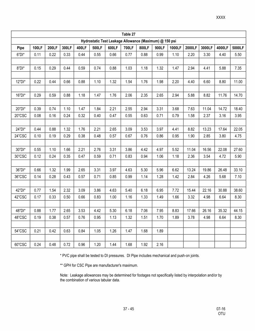
XXXX
37 - 45 07-16 OTU
Table 27
Hydrostatic Test Leakage Allowance (Maximum) @ 150 psi
Pipe 100LF 200LF 300LF 400LF 500LF 600LF 700LF 800LF 900LF 1000LF 2000LF 3000LF 4000LF 5000LF
6”DI* 0.11 0.22 0.33 0.44 0.55 0.66 0.77 0.88 0.99 1.10 2.20 3.30 4.40 5.50
8”DI* 0.15 0.29 0.44 0.59 0.74 0.88 1.03 1.18 1.32 1.47 2.94 4.41 5.88 7.35
12”DI* 0.22 0.44 0.66 0.88 1.10 1.32 1.54 1.76 1.98 2.20 4.40 6.60 8.80 11.00
16”DI* 0.29 0.59 0.88 1.18 1.47 1.76 2.06 2.35 2.65 2.94 5.88 8.82 11.76 14.70
20”DI* 0.39 0.74 1.10 1.47 1.84 2.21 2.55 2.94 3.31 3.68 7.63 11.04 14.72 18.40
20”CSC 0.08 0.16 0.24 0.32 0.40 0.47 0.55 0.63 0.71 0.79 1.58 2.37 3.16 3.95
24”DI* 0.44 0.88 1.32 1.76 2.21 2.65 3.09 3.53 3.97 4.41 8.82 13.23 17.64 22.05
24”CSC 0.10 0.19 0.29 0.38 0.48 0.57 0.67 0.76 0.86 0.95 1.90 2.85 3.80 4.75
30”DI* 0.55 1.10 1.66 2.21 2.76 3.31 3.86 4.42 4.97 5.52 11.04 16.56 22.08 27.60
30”CSC 0.12 0.24 0.35 0.47 0.59 0.71 0.83 0.94 1.06 1.18 2.36 3.54 4.72 5.90
36”DI* 0.66 1.32 1.99 2.65 3.31 3.97 4.63 5.30 5.96 6.62 13.24 19.86 26.48 33.10
36”CSC 0.14 0.28 0.43 0.57 0.71 0.85 0.99 1.14 1.28 1.42 2.84 4.26 5.68 7.10
42”DI* 0.77 1.54 2.32 3.09 3.86 4.63 5.40 6.18 6.95 7.72 15.44 22.16 30.88 38.60
42”CSC 0.17 0.33 0.50 0.66 0.83 1.00 1.16 1.33 1.49 1.66 3.32 4.98 6.64 8.30
48”DI* 0.88 1.77 2.65 3.53 4.42 5.30 6.18 7.06 7.95 8.83 17.66 26.16 35.32 44.15
48”CSC 0.19 0.38 0.57 0.76 0.95 1.13 1.32 1.51 1.70 1.89 3.78 4.98 6.64 8.30
54”CSC 0.21 0.42 0.63 0.84 1.05 1.26 1.47 1.68 1.89
60”CSC 0.24 0.48 0.72 0.96 1.20 1.44 1.68 1.92 2.16
* PVC pipe shall be tested to DI pressures. DI Pipe includes mechanical and push-on joints.
** GPH for CSC Pipe are manufacturer's maximum.
Note: Leakage allowances may be determined for footages not specifically listed by interpolation and/or by the combination of various tabular data.
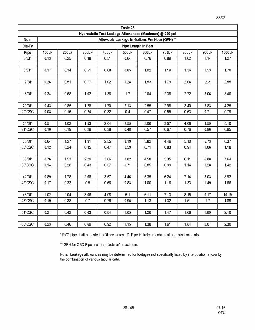
XXXX
38 - 45 07-16 OTU
Table 28
Hydrostatic Test Leakage Allowances (Maximum) @ 200 psi
Nom Allowable Leakage in Gallons Per Hour (GPH) **
Dia-Ty Pipe Length in Feet
Pipe 100LF 200LF 300LF 400LF 500LF 600LF 700LF 800LF 900LF 1000LF
6”DI* 0.13 0.25 0.38 0.51 0.64 0.76 0.89 1.02 1.14 1.27
8”DI* 0.17 0.34 0.51 0.68 0.85 1.02 1.19 1.36 1.53 1.70
12”DI* 0.26 0.51 0.77 1.02 1.28 1.53 1.79 2.04 2.3 2.55
16”DI* 0.34 0.68 1.02 1.36 1.7 2.04 2.38 2.72 3.06 3.40
20”DI* 0.43 0.85 1.28 1.70 2.13 2.55 2.98 3.40 3.83 4.25
20”CSC 0.08 0.16 0.24 0.32 0.4 0.47 0.55 0.63 0.71 0.79
24”DI* 0.51 1.02 1.53 2.04 2.55 3.06 3.57 4.08 3.59 5.10
24”CSC 0.10 0.19 0.29 0.38 0.48 0.57 0.67 0.76 0.86 0.95
30”DI* 0.64 1.27 1.91 2.55 3.19 3.82 4.46 5.10 5.73 6.37
30”CSC 0.12 0.24 0.35 0.47 0.59 0.71 0.83 0.94 1.06 1.18
36”DI* 0.76 1.53 2.29 3.06 3.82 4.58 5.35 6.11 6.88 7.64
36”CSC 0.14 0.28 0.43 0.57 0.71 0.85 0.99 1.14 1.28 1.42
42”DI* 0.89 1.78 2.68 3.57 4.46 5.35 6.24 7.14 8.03 8.92
42”CSC 0.17 0.33 0.5 0.66 0.83 1.00 1.16 1.33 1.49 1.66
48”DI* 1.02 2.04 3.06 4.08 5.1 6.11 7.13 8.15 9.17 10.19
48”CSC 0.19 0.38 0.7 0.76 0.95 1.13 1.32 1.51 1.7 1.89
54”CSC 0.21 0.42 0.63 0.84 1.05 1.26 1.47 1.68 1.89 2.10
60”CSC 0.23 0.46 0.69 0.92 1.15 1.38 1.61 1.84 2.07 2.30
* PVC pipe shall be tested to DI pressures. DI Pipe includes mechanical and push-on joints.
** GPH for CSC Pipe are manufacturer's maximum.
Note: Leakage allowances may be determined for footages not specifically listed by interpolation and/or by the combination of various tabular data.

XXXX
39 - 45 07-16 OTU
3.6. Disinfection of New Mains Utilizing Machine Chlorination.
After the new mains have successfully passed the pressure test specified in Section 3.4.3, “Hydrostatic Tests”, the San Antonio Water System will disinfect those mains shown on the plans or otherwise indicated as “Machine Chlorination”. This disinfection is to include chlorination, flushing, and placing the mains in service. All other disinfection requirements shall be accomplished by the Contractor. Disinfection by the Contractor is limited to sections of pipe less than 800 feet in length between sections.
3.6.1. Operation of Valves.
During and after disinfection of mains less than or equal to 16 inches in diameter, the Contractor shall be notified by the Inspector sufficiently in advance (2 work days) to enable the Contractor to have a competent representative present whenever valves are to be operated that will affect the pressure in any part of the work for which the Contractor is responsible.
3.6.2. Contractor's Personnel and Equipment.
The Contractor is to supply labor and equipment necessary to make all excavations required for chlorination, equipment connections, subsequent flushing, and placing the mains in service.
3.6.3. Safeguarding and Backfilling Open Holes.
The Contractor is to be responsible for safeguarding any open holes excavated or left open for flushing and disinfection purposes. Following completion of disinfection, the Contractor is to backfill such holes in accordance with appropriate provisions of Subarticle 3.3, “Backfill”.
3.6.4. Disinfection of Mains Utilizing Dry Calcium Hypochlorite.
Mains are to be disinfected with dry Calcium Hypochlorite (HTH) where shown on the plans or as directed and shall not exceed a total length of 800 feet. This method will also be followed for main repairs. Contractor shall utilize appropriate safety measures to protect personnel during disinfection operation.
3.6.5. Dosage.
The Contractor is to disinfect the new or replaced mains with Calcium Hypochlorite (HTH) of 70 percent available chlorine. Sufficient Calcium Hypochlorite (HTH) is to be used to obtain a minimum chlorine concentration of 50 ppm. The following Table 29, Chlorine Dosage, is included for the convenience of the Contractor:
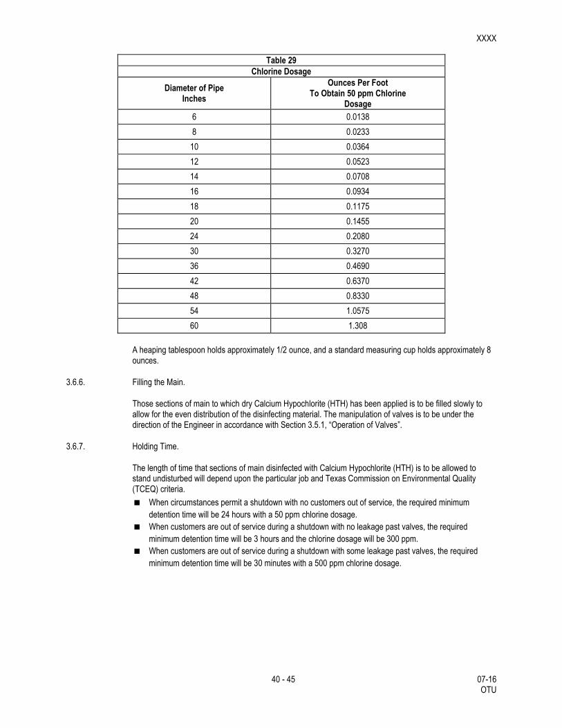
XXXX
40 - 45 07-16 OTU
Table 29
Chlorine Dosage
Diameter of Pipe Inches
Ounces Per Foot To Obtain 50 ppm Chlorine
Dosage
6 0.0138
8 0.0233
10 0.0364
12 0.0523
14 0.0708
16 0.0934
18 0.1175
20 0.1455
24 0.2080
30 0.3270
36 0.4690
42 0.6370
48 0.8330
54 1.0575
60 1.308
A heaping tablespoon holds approximately 1/2 ounce, and a standard measuring cup holds approximately 8 ounces.
3.6.6. Filling the Main.
Those sections of main to which dry Calcium Hypochlorite (HTH) has been applied is to be filled slowly to allow for the even distribution of the disinfecting material. The manipulation of valves is to be under the direction of the Engineer in accordance with Section 3.5.1, “Operation of Valves”.
3.6.7. Holding Time.
The length of time that sections of main disinfected with Calcium Hypochlorite (HTH) is to be allowed to stand undisturbed will depend upon the particular job and Texas Commission on Environmental Quality (TCEQ) criteria.
When circumstances permit a shutdown with no customers out of service, the required minimum
detention time will be 24 hours with a 50 ppm chlorine dosage.
When customers are out of service during a shutdown with no leakage past valves, the required
minimum detention time will be 3 hours and the chlorine dosage will be 300 ppm.
When customers are out of service during a shutdown with some leakage past valves, the required
minimum detention time will be 30 minutes with a 500 ppm chlorine dosage.
XXXX
41 - 45 07-16 OTU
3.6.8. Flushing.
Following the expiration of the specified holding time, the treated section of main is to be flushed thoroughly by the Contractor in accordance with the applicable provisions of Subarticle 3.4, “Flushing and Testing Mains”. Flushing is to continue until no chlorine remains detectable by taste or odor or until the chlorine residual is less than 0.3 ppm. The Contractor must make provisions for the disposal and runoff of the flushing operations in order to minimize erosion or impact to residents.
3.6.9. Preventing Reverse Flow
Valves are to be manipulated so that the strong chlorine solution in the line being treated will be flushed out of the main and will not flow back into the line supplying the water.
3.6.10. Supervision
All disinfection is to be done as be done under the general supervision of the Water System Company.
3.6.11. Additional Treatment
Should the new main fail to meet minimum public health standards for bacteriological quality after flushing, further treatment is to be as directed. If further disinfection is required, chlorination is to be done in accordance with Subarticle 3.5, “Disinfection of New Mains Utilizing Machine Chlorination”. In no case, however, is the new line to be acceptable as complete and satisfactory until the bacteriological quality of the water taken from the main meets the Standards of the TCEQ.
If an open hole is unsafe and does not have proper trench protection, owner’s chlorination crew will not chlorinate project until acceptable trench protection is provided.
3.7. Service Supply Lines
Service supply lines and fittings shall conform to material specifications and shall be installed by the contractor as specified herein, or as directed by the engineer and in accordance with plans. Service supply lines in High Pressure Zones should be installed with two strap service saddle clamps.
3.7.1. Designation of Service Supply Lines
A service supply line located between the temporary water main and the inlet side of the water meter is designated as a “water service line”. A service supply line located between the outlet side of the water meter to the point of connection within the limits of the Customers lot or property is designated as “Customer’s yard piping”. Services 2” and smaller are designated “small services”; services 4” and larger are designated “large services”.
Reconnect any services shown on the plans and along the alignment of the temporary water main to the temporary water main, so the existing main can be taken out of service.
Service Line Installation: Unless otherwise notified, service reconnects shall be installed as described herein, and in plans. Unless otherwise indicated, existing meter and meter box relocation shall be included in the service line installation.
All service line installation shall include a dielectric union to be installed within the meter box on the outlet side of the meter, as shown in plans.
Cutting, excavation, backfill and replacement of pavement shall be done as specified herein and in accordance with applicable sections of this specification and the contract documents. The minimum trench width for small service lines shall be 8 inches, while the minimum trench width for large service Lines shall be the nominal pipe diameter plus 16 inches, except when specified otherwise by the Engineer. For ¾” to 2"
XXXX
42 - 45 07-16 OTU
All service lines shall be installed in accordance with plans, and specifications, except that two strap service saddle clamps shall be installed for all tap connections made on water mains located within boundaries of Pressure Zones (formally known as Service Levels) 9 through 16.
Small service lines shall be embedded in sand in accordance with specification
When approved by the Construction Inspector, the Contractor may lay the new service line from the corporation stop to the curb stop or angle valve. Upon completion, the Contractor shall isolate the new service line by closing the curb stop or angle valve until the meter box is set.
Tapping PVC (C-900): Tapping of PVC must be done in accordance with Uni-Bell procedures. Direct Tapping will not be allowed. All drill cutting tools must be the "shell type" with internal teeth or double slots which will retain the coupon.
The shell cutters must be designed for C-900 pipe, thus having sufficient root depth to handle the heavier walled pipe.
Small Service Lines: Copper tubing shall be used for ¾” through 2" service lines. Brass fittings for ¾” and 1" service lines shall be of the flared or compression type for the use with Type 'K' soft annealed copper tubing. Brass fittings for 1½" and 2" lines shall be of the flared or compression type for use with type 'K' soft annealed copper tubing, except as modified by this specification.
Copper tubing shall be cut squarely by using an approved cutting tool and by avoiding excessive pressure on the cutting wheels which might bend or flatten the pipe walls. Following the copper tubing cut, but before flaring, a reamer shall be used to remove the inside rolled lip from the tubing. Flared ends shall be expanded by the use of a flaring tool using care to avoid splitting, crimping, or overstressing the metal. Pipe adjacent to the fittings shall be straight for at least 10 inches. Bending of tubing shall be accomplished by using an appropriate sized bending tool. No kinks, dents, flats, or crimps will be permitted, and should such occur, the damaged section shall be cut out and replaced. When compression fittings are used, the copper tubing shall be cut squarely prior to insertion into the fitting Final assembly shall be in accordance with the manufacturers recommendations.
Reconnecting Service Lines: Both old and new water mains at existing service line connections as shown on the plans shall be exposed. The old main shall be exposed for the purpose of gaining access to the existing service corporation stop and the new main for the purpose of installing the new corporation stop. The new main shall be exposed for the purpose of being drilled and tapped with an approved tapping machine, a new corporation stop installed under pressure, and the trench extended laterally to expose a sufficient length of the existing service line to provide slack to bend it to position for tying to the new corporation stop. After suitable notification to the Customer, the Contractor shall “kill” the existing service by closing the corporation stop, removing the existing flare nut, inserting the existing flared nut on the corporation stop if the main is non-ferrous, or plugging the existing service line at the main if the main is ferrous. The Contractor shall then immediately open the stop and restore water service to the Customer. Where it is not possible to obtain sufficient length in the existing service to tie directly to the new main, at the direction of the Engineer, the Contractor shall splice the necessary length of new tubing and tie it to the existing service by means of a compression coupling at a point as close as practicable to the new main.
Cutting and bending of the tubing, introduction of slack to compensate for soil movement, and completion of the installation shall be as specified in this specification.
Where old and new mains are on opposite sides of the street, service lines may be installed under the street pavement by boring rather than trenching.
Large Service Lines: DI pipe and cast-iron fittings used for metered service lines and non-metered fire service lines larger than 2” shall be installed in accordance with the applicable provisions of this specification, except where otherwise approved by the Engineer.
XXXX
43 - 45 07-16 OTU
3.7.2. Water Service for Fire Lines
Start of Work: Three working days notice will be given to the assigned Inspector prior to start of a project after permit has been issued. The Contractor shall start his work at a tie-in or point designated by the Engineer. Pipe shall be laid with bell ends facing in the direction of laying, unless otherwise authorized or directed by the Engineer. All valves and fire hydrants must be installed as soon as pipe laying reaches their established location. Pipe shall be installed to the required lines and grades with fittings, valves, and hydrants placed at the required locations. Spigots shall be centered in bells or collars, all valves and hydrant stems shall be set plumb, and fire hydrant nozzles shall face as shown on the plans or as directed by the Engineer. No valve or other control on the existing system shall be operated for any purpose by the Contractor unless a representative of the San Antonio Water System is present.
Crossing Other Underground Lines:
New fire line services crossing any other utilities shall have a minimum of 48 inches of cover over the top of the pipe unless otherwise waived or modified by the Engineer. Excavation around other utilities shall be done by hand for at least 12 inches all around. Any damage to other utilities shall be reported to the governing entity/owner of said utility as well as the Inspector.
Pipe Grade:
Fire line services shall have a minimum of 48 inches of cover for mains 16” and below, and 60 inches for mains 20” and above, over the top of the pipe unless otherwise waived or modified by the Engineer. Pipe grades shall be as required by the plans or as directed by the Engineer. Grades shall be met as specified. Precautions shall be taken to insure that the pipe barrel has uniform contact with the Modified Grade 5 for its full length except at couplings. Couplings shall not be in contact with the original trench bottom prior to backfilling. Modified Grade 5 material shall be placed under the coupling and compacted by hand prior to backfilling so as to provide an even bearing surface under the coupling and pipe. Changes in grade shall be made only at joints.
Modified Grade 5 Materials:
Prior to placing pipe in a trench, the trench shall have been excavated to the proper depth as required of these specifications. Approved imported materials or Engineer approved materials selected from suitable fines derived from the excavation shall be smoothly worked across the entire width of the trench bottom to provide a supporting cushion.
Structures to Support Pipe:
Where as the bottom of a trench at subgrade consist of material that is notably unstable by the Engineer and cannot be removed and replaced with approved material may be properly compacted in place to support the pipe. The Contractor shall also construct a foundation for the pipe consisting of piling, concrete beams, or other supports in accordance with plans prepared by the Engineer.
Lowering Materials into Trench:
Proper implements, tools, and facilities satisfactory to the Engineer shall be provided and used by the Contractor for the safe and convenient completion of work. All pipe, fittings, valves, and hydrants shall be carefully lowered into the trench piece by piece, by means of a derrick, ropes, or other suitable tools or equipment in such a manner as to prevent damage to water service materials and protective coatings and linings. Under no circumstances shall water service materials, pipes, fittings, etc., be dropped or dumped into the trench. Extreme care shall be taken to avoid damaging polywrap films. No chains or slings shall be allowed unless the entire sling is wrapped with a protective nylon web sock.

XXXX
44 - 45 07-16 OTU
Laying of Pipe:
Every precaution shall be taken to prevent foreign material from entering the pipe during its installation. Under adverse trench conditions or otherwise required by the Engineer, a heavy, tightly woven canvas bag of suitably sized shall be placed over each of the pipe.
The Canvas bag shall be left in place until a connection is made to the adjacent pipe. The interior of each pipe shall be inspected for defects, and the pipe shall be rejected if any defects are found.
After placing a length of pipe in the trench, the jointed end shall be centered on the pipe already in place, forced into place, brought to correct line and grade, and completed in accordance with the requirements of these Specifications. The pipe shall be secured in place with approved backfill material tamped around it. Pipe and fittings which do not allow a sufficient and uniform space for joints shall be rejected and shall be replaced with pipe and fittings of proper dimensions. Precautions shall be taken to prevent dirt or other foreign matter from entering the joint space.
At times when pipe laying is halted, the open end of pipe in the trench shall be closed by a watertight plug or other means approved by the Engineer. Pipe in the trench which cannot temporarily be joined shall be capped or plugged at each end to make it watertight. This provision shall apply during all periods when pipe laying is not in progress. Should water enter the trench, the seal shall remain in place until the trench is pumped completely dry. The Contractor shall provide all plugs and caps of the various sizes required.
Deviations in Line or Grade:
Wherever obstructions not shown on the plans are encountered during the progress of the work and interfere to an extent that an alteration in the plan is required, the Construction Inspector shall have the authority to change the plans and direct a deviation from the line and grade or to arrange with the owners of the structures for the removal, relocation, or reconstruction of the obstructions. Any deviation from the line shall be accomplished by the use of appropriate bends unless such requirement is specifically waived by the Construction Inspector.
Whenever it is necessary to deflect pipe from a straight line, the deflection shall be as directed by the Construction Inspector and as described herein. In no case shall the amounts exceed those shown in Table 19 "Maximum Deflections of Ductile-Iron Pipe" for ductile-iron pipe
Cutting Pipe:
The cutting of pipe for inserting valves, fittings, or closure pieces shall be accomplished in a neat manner so as to produce a smooth end at right angles to the axis of the pipe. The recommendations of the pipe manufacturer shall be strictly followed by the Contractor. Only qualified and experienced workmen shall be used and, under no circumstances, shall a workman not equipped with proper safety goggles, helmet and all other required safety attire be permitted to engage in this work.
Asbestos-Cement (AC):
No field cutting will be allowed on asbestos cement pipe. Installation of fire line services to AC pipe mains shall be accomplished by removing one full joint of AC pipe and replacing with appropriate PVC or Ductile Iron pipe and fittings. All cuts made on ductile-iron pipe shall be done with a power saw. The cuts shall be made at right angles to the pipe axis and shall be smooth. The edges of the cut shall be finished smoothly with a hand or machine tool to remove all rough edges. The outside edge of pipe should be finished with a small taper at an angle of about 30 degrees. Solid sleeves or cast couplings shall be allowed on precast/prefab vaults only. All other fire line services shall be installed with full joints of pipe.

XXXX
45 - 45 07-16 OTU
Joint Assembly:
Rubber Ring Joints: The installation of pipe and the assembly of rubber ring joints for Ductile-Iron pipe
shall conform to the pipe manufacturer's assembly instructions. The method of inserting spigot ends of
pipe in bells or collars known as "stabbing" shall not be permitted. Spigot ends of pipe must be properly
inserted in the joint by means of suitable pushing/pulling devices or a manufacture approved method.
Mechanical Couplings: Mechanical couplings shall be assembled and installed according to the
standards recommended by the manufacturer.
Mechanical coupling consists of a cylindrical steel middle ring, two steel follower rings, two rubber
compound gaskets, and a set of steel bolts. The middle ring is flared at each end to receive the wedge-
shaped gasket which is compressed between the middle ring flare and the outer surface of the pipe by
pressure exerted on the follower rings through the bolt circle.
Prior to the installation of the mechanical coupling, the pipe ends shall be cleaned by wire brush or other
acceptable method to provide a smooth bearing surface for the rubber compression gasket. The pipe
shall be marked to align the end of the coupling which will center it over the joint. After positioning, the
nuts shall be drawn up finger tight. Uniform pressure on the gaskets shall be applied by tightening
alternate bolts on the opposite side of the circle in incremental amounts. Soap and final tensioning shall
be accomplished with a torque wrench and in a matter similar to the tightening procedure after 15
minutes.
Restrained Joints: Restrained Joints shall be installed as shown on the plans or as directed by the
Construction Inspector. Installation shall conform to the manufacture’s recommendations.
3.8. Installation of the Nonmetallic Pipe Detection System.
The nonmetallic pipe detection system is to be installed concurrently with the proposed pipe placement. Tracer wire shall be utilized for location purposes and taped directly to the pipe. The tracer wire shall be solid core (14 gauge insulated), and shall be taper to the main in 10-inch increments. Wire shall also come up to the top of valve extensions and fire hydrant stems, as directed by the Water System Inspector.
4. MEASUREMENT
This Item will be measured as follows: “Temporary Water Main” for the temporary water pipe of the various type and size shown on the plans, will be measured by the lump sum.
5. PAYMENT
The work performed and materials furnished in accordance with this Item and measured as provided under “Measurement” will be paid for on a lump sum basis. Payment for “Temporary Water Main” shall include all required items to install the temporary water main as shown in the plans, tie-in the temporary water main to the existing water main, transfer services to the temporary water main, maintain the temporary water main during construction of the new water main, and remove the temporary water main after the new main has been tied-into the existing water main and the services have been connected to the new main. The lump sum price shall be full compensation for all labor, equipment materials, tool, excavation, embedment material, backfill, compaction, water tie-ins, hydrostatic testing, disinfection, tapping sleeves and valves, fittings, piping, valves, air release assemblies, temporary water main removal, hauling and disposition of surplus material, and incidentals necessary to complete the work in accordance with the plans and specifications.