specif ications - sandc.com · pad-mounted enclosures meet the requirements of ansi standard...
TRANSCRIPT
S&C Source-Transfer Vista®
Underground Distribution SwitchgearOutdoor Distribution (15.5 kV through 38 kV)
With Micro-AT ® Control
October 17, 2016© S&C Electric Company 2001-2016, all rights reserved
Specification Bulletin 683-31
Conditions of Sale STANDARD: The seller’s standard conditions of sale set forth in Price Sheet 150 apply.
SPECIAL TO THIS PRODUCT:
INCLUSIONS: S&C Source-Transfer Vista Underground Distribution Switchgear (UDS) provides fully automatic primary-selective service and fault protection for up to three critical load circuits. Each unit includes 600-ampere load-interrupter switches (900-ampere as an option); microprocessor-controlled, resettable, vacuum fault interrupters; three-phase voltage sensing for each source; motor operators for each source way; and self-power by means of voltage transformers, all enclosed in a submersible, SF6-insulated, welded-steel tank. The S&C Micro-AT Source-Transfer Control is housed in a low-voltage enclosure/compartment. Source-Transfer Vista UDS is rated through 38 kV and 25 kA symmetrical and is available in three styles: UnderCover™, vault-mounted, and pad-mounted.
The three-position (Closed -Open -Grounded) load-interrupter switches provide three-pole live switching of 600- or 900-ampere main feeders. They provide a visible gap when open and internal grounding for all three phases with no cable handling or exposure to medium voltage. The load-interrupter switches have a 10-time duty-cycle fault-closing rating at currents up to the short-circuit rating of the gear.
The vacuum fault interrupters, in series with three-position (Closed-Open-Grounded) disconnects, provide three-pole load switching and fault interruption through 25 kA symmetrical or single-pole load switching and fault interruption through 12.5 kA symmetrical. (For other possible ratings, refer to the nearest S&C Sales Office). Fault interrupters provide protection of 600- or 900-ampere main feeders or 200-, 600-, or 900-ampere taps, laterals, or subloops. Fault interruption is initiated by a programmable overcurrent control. For single-pole fault interrupters, the overcurrent control can also be programmed to provide three-pole fault interruption.
A manual handle is provided for operating load-interrupter switches and fault interrupters. Operating mechanisms are designed to prevent inadvertent switching from the Closed position directly to Grounded position, and vice versa.
Large windows provide a clear view of the open gap, ground position, and ground bus, allowing the operator to easily confirm the positions of the load-interrupter switches and disconnects of the fault interrupters. Trip indicators are easily visible through the windows.
Terminals are equipped with 200-ampere bushing wells or 600- or 900-ampere bushings as specified. Bushing and bushing-well interfaces conform with IEEE Standard 386 and accept all standard insulated connectors and inserts.
Vista UDS has been certified as arc resistant per IEC 298 Appendix AA for fault currents up to 12.5 kA symmetrical for 15 cycles (25 kA symmetrical to units rated 25 kA short circuit). Arc resistance is standard for UnderCover and pad-mounted styles. For vault-mounted style, Catalog Number Suffix “-N” must be specified, in which case a flange will be welded to the pressure relief device for connection of user-supplied piping to vent exhaust gases out of the vault area.
Overcurrent ControlFault interruption is initiated by a programmable over- current control housed in a watertight enclosure attached to the gear. The control is programmed using a personal computer connected through an adapter cable, listed in Table 8 on page 11. Power and input signals for the control are provided by current transformers. A variety of time-current characteristic (TCC) curves are available—standard “E” speed curves, “K” speed curves, innovative “coordinating” speed tap and main curves, and relay curves per IEEE C37.112-1996.
Coordinating-speed tap curves are used for fault interrupters feeding subloop taps and are specifically designed to optimize coordination with load-side weak link/backup current-limiting fuse combinations, and source-side relays with low time-dial settings. Coordinating-speed main curves are used for fault interrupters on main feeders and have a longer minimum response time and a different shape to coordinate with tap-interrupter curves.
The coordinating-speed curves have phase-overcurrent and ground-overcurrent settings. The ground-overcurrent setting is only available for three-pole tripping of the fault interrupters and can be turned off, if desired. These curves can be tailored to the application using a variety of instan-taneous and definite-time settings.
Specif ications

S&C Source-Transfer Vista® Underground Distribution Switchgear
2 S&C Specification Bulletin 683-31
Conditions of Sale—Continued UnderCover StyleWhen the UnderCover Style is specified, a stainless steel tank with submersible wiring is furnished suitable for underground installation. A mild-steel or, optionally, stainless steel low-voltage enclosure is mounted on a customer-supplied pad at grade level. It is connected to the tank with cabling up to 45 feet (1372 cm) in length.«
Vault-Mounted StyleTwo versions of this style are available: Wet vault-mounted style is intended for vaults that are subject to periodic flooding and includes submersible wiring and electrical components. Dry vault-mounted style is intended for vaults that are not subject to periodic flooding and does not include submersible wiring and electrical components.
When the wet-vault-mounted style is specified, a stainless steel tank is furnished, suitable for mounting on the floor or wall of a vault. When the dry-vault-mounted style is specified, a mild-steel tank is furnished. The mild-steel or, optionally, stainless steel low-voltage enclosure is mounted on the vault floor or wall; it is connected to the tank with cabling up to 45 feet (1372 cm) in length.«
Pad-Mounted StyleWhen the pad-mounted style is specified, a mild-steel or, optionally, stainless-steel enclosure is furnished. A mild-steel or, optionally, stainless steel low-voltage compartment is mounted on the side of the enclosure.
Although the Vista UDS tank itself is submersible, many of the electrical components mounted to the tank are not. Special submersible components and wiring are provided when the UnderCover Style or wet vault-mounted style is specified. Contact the nearest S&C Sales Office for information on pad-mounted style units with submersible wiring.
Pad-mounted enclosures meet the requirements of ANSI Standard C57.12.28 for enclosure integrity. The top of the enclosure is hinged on both sides for convenient access to the operating and termination compartments. The roof of the enclosure is sloped outward to ensure water flows away from the switchgear. A removable panel provides access to the elbows and cables and is secured by the overlapping padlockable top. A resilient closed-cell gasket on the enclosure bottom flange protects the finish from being scratched during installation. Enclosures are protected from corrosion by S&C’s Ultradur® Finishing System.
Voltage and Current SensingThree-phase voltage sensing is standard for each source. Three-phase current sensing is provided when the overcurrent lockout option is specified.
Motor Operators and ControlsMotor operators on the load-interrupter switch ways allow switching between the sources. A motor operator is provided for each of the two source ways in common-bus switchgear. Three motor operators—one for each source way and the tie switch way—are provided for split-bus switchgear. The motor operator controls are located within the low-voltage enclosure/compartment. Each motor operator is provided with a control board that includes Close, Open, and Ground pushbuttons; switch-position indicating lamps; operation a counter; a lamp test button; and a receptacle for a portable remote control station. (The bus tie-switch for split-bus configurations does not have a ground position.) For additional motor-operated ways, please contact your nearest S&C Sales Office.
Potential Indication with Test FeatureThe optional potential indicator features a liquid-crystal display that indicates the presence of voltage for each phase. A solar panel supplies power for testing of the potential-indication circuit. This feature is available with or without provisions for low-voltage phasing. Cable testing for faults can be performed through the back of a user-specified elbow or feedthrough insert, eliminating the need for cable handling or parking stands.
Micro-AT® Source-Transfer ControlThe S&C Micro-AT Source-Transfer Control, located within the low-voltage enclosure/compartment, ensures a high degree of critical-load continuity by minimizing interruptions resulting from the loss of one source. Excluding the intentional time delay to coordinate with upstream protective devices and/or transition dwell time, transfer is achieved in 6 seconds.
The Micro-AT control uses an advanced microprocessor to perform control operations, as directed by settings programmed into the device at the factory and in the field. Such settings—consisting of the control’s operating charac-teristics and voltage-, current-, and time-related operating parameters—are entered into the control by means of a keypad on the front panel.
« Common-bus configuration switchgear requires a minimum of 5-inch (127-mm) diameter conduit. Split-bus configuration switchgear requires a minimum of 6-inch (152-mm) diameter conduit.
S&C Specification Bulletin 683-31 3
S&C Source-Transfer Vista® Underground Distribution Switchgear
An unbalance-detection feature may be field-programmed in the Micro-AT Source-Transfer Control. This feature protects the loads from any source-side open-phase condition at the same voltage as the Vista Underground Distribution Switchgear, whether caused by utility-line burndown, broken conductors, single-phase switching, equipment malfunctions, or single-phasing resulting from blown source-side fuses. The unbalance detection feature continuously develops and monitors the negative-sequence voltage to detect any unbalance present as the result of an open-phase condition. If the voltage unbalance exceeds a preset reference level for a period of time sufficient to confirm the loss is not transient, an output signal is produced that initiates automatic transfer to the other source.
An optional overcurrent lockout feature prevents an automatic transfer operation that would close a source interrupter switch into a fault. A light-emitting diode lamp indicates when a lockout has occurred. Test keys are provided for simulating an overcurrent condition on each source.
Control power for the source-transfer control is provided by voltage transformers internal to the tank.
Common-Bus Primary-Selective System ApplicationsUnder normal operating conditions in a common-bus primary-selective system, the preferred-source load-interrupter switch is closed and the alternate-source load-interrupter switch is open. The Micro-AT Source-Transfer Control monitors both sources and initiates automatic transfer to the alternate source if preferred source voltage has been lost or reduced below a user-determined level for a programmed period of time. The method for returning to the normal circuit configuration can be field programmed.
Split-Bus Primary-Selective System ApplicationsIn a split-bus primary-selective system, the circuit is divided into two sections by a normally open bus-tie switch. Each bus section has a normally closed load-interrupter switch, so the two loads receive power from separate sources. Each source is the preferred source for its section and the alternate source for the other section. The Micro-AT Source-Transfer Control monitors both sources and initiates automatic transfer if voltage on one source has been lost or reduced below a user-determined level. Usually each
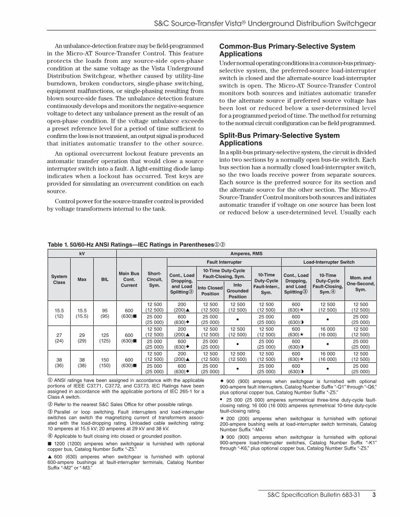
Table 1. 50/60-Hz ANSI Ratings—IEC Ratings in Parentheses①②
kV Amperes, RMS
System Class
Max BILMain Bus
Cont. Current
Short-Circuit, Sym.
Fault Interrupter Load-Interrupter Switch
Cont., Load Dropping, and Load
Splitting③
10-Time Duty-Cycle Fault-Closing, Sym. 10-Time
Duty-Cycle Fault-Interr.,
Sym.
Cont., Load Dropping, and Load
Splitting③
10-Time Duty-Cycle
Fault-Closing, Sym.④
Mom. and One-Second,
Sym.Into Closed Position
Into Grounded Position
15.5 (12)
15.5 (15.5)
95 (95)
600 (630)¢
12 500 (12 500)
200 (200)p
12 500 (12 500)
12 500 (12 500)
12 500 (12 500)
600 (630)«
12 500 (12 500)
12 500 (12 500)
25 000 (25 000)
600 (630)®
25 000 (25 000) • 25 000
(25 000)600
(630)◑ • 25 000 (25 000)
27 (24)
29 (29)
125 (125)
600 (630)¢
12 500 (12 500)
200 (200)p
12 500 (12 500)
12 500 (12 500)
12 500 (12 500)
600 (630)«
16 000 (16 000)
12 500 (12 500)
25 000 (25 000)
600 (630)®
25 000 (25 000) • 25 000
(25 000)600
(630)◑ • 25 000 (25 000)
38 (36)
38 (38)
150 (150)
600 (630)¢
12 500 (12 500)
200 (200)p
12 500 (12 500)
12 500 (12 500)
12 500 (12 500)
600 (630)«
16 000 (16 000)
12 500 (12 500)
25 000 (25 000)
600 (630)®
25 000 (25 000) • 25 000
(25 000)600
(630)◑ • 25 000 (25 000)
① ANSI ratings have been assigned in accordance with the applicable portions of IEEE C37.71, C37.72, and C37.73. IEC Ratings have been assigned in accordance with the applicable portions of IEC 265-1 for a Class A switch.② Refer to the nearest S&C Sales Office for other possible ratings.③ Parallel or loop switching. Fault interrupters and load-interrupter switches can switch the magnetizing current of transformers associ-ated with the load-dropping rating. Unloaded cable switching rating: 10 amperes at 15.5 kV; 20 amperes at 29 kV and 38 kV.④ Applicable to fault closing into closed or grounded position.
¢ 1200 (1200) amperes when switchgear is furnished with optional copper bus, Catalog Number Suffix “-Z5.”
p 600 (630) amperes when switchgear is furnished with optional 600-ampere bushings at fault-interrupter terminals, Catalog Number Suffix “-M2” or “-M3.”
® 900 (900) amperes when switchgear is furnished with optional 900-ampere fault interrupters, Catalog Number Suffix “-Q1” through “-Q6,” plus optional copper bus, Catalog Number Suffix “-Z5.”
• 25 000 (25 000) amperes symmetrical three-time duty-cycle fault- closing rating; 16 000 (16 000) amperes symmetrical 10-time duty-cycle fault-closing rating.
« 200 (200) amperes when switchgear is furnished with optional 200-ampere bushing wells at load-interrupter switch terminals, Catalog Number Suffix “-M4.”
◑ 900 (900) amperes when switchgear is furnished with optional 900-ampere load-interrupter switches, Catalog Number Suffix “-K1” through “-K6,” plus optional copper bus, Catalog Number Suffix “-Z5.”

S&C Source-Transfer Vista® Underground Distribution Switchgear
4 S&C Specification Bulletin 683-31
Conditions of Sale —Continued source cable is loaded to capacity. Because under emergency conditions some loads can usually be shed, it is not necessary for either source to carry the switchgear’s total load for a long period of time. The method for returning to the normal circuit configuration can be field programmed.
APPLICATION NOTES: The following items should be considered when applying Source-Transfer Vista UDS:
Ungrounded systems. The S&C voltage sensors are connected phase to ground and are therefore not intended for use on ungrounded systems. Contact the nearest S&C Sales Office for information on applying Source-Transfer Vista UDS on ungrounded systems.
Uni-grounded and resistance-grounded systems. Uni-grounded and resistance-grounded systems require power provided by a phase-to-phase-connected voltage transformer. Therefore, power must be supplied by an external source if a Source-Transfer Vista UDS is to be applied on a uni-grounded or resistance-grounded system. Contact the nearest S&C Sales Office.
Fusing of Voltage TransformersThe voltage transformers that provide power to Source-Transfer Vista UDS are fused external to the tank on the secondary side of the transformer. National Electric Code Article 450.3 (A) states that transformers over 600 volts nominal shall be protected on the primary side. Contact the nearest S&C Sales Office for information on applications that require NEC compliance.
How to Order1. Select the catalog number of the desired unit of
Source-Transfer Vista Underground Distribution Switchgear from Tables 2 and 3 on pages 5 and 6.
2. Select the appropriate switchgear style suffix from Table 4 on page 6.
3. For models rated 12.5 kA only, select the appropriate fault interrupter suffix from Table 5 on page 7.
4. Select the appropriate voltage transformer suffix from Table 6 on page 7.
5. Select the suffix(es) of the desired optional features from Table 7 on pages 8 through 10.
6. Obtain the catalog number of desired accessories and/or touch-up kit from Tables 8 and 11 on page 11.
S&C Specification Bulletin 683-31 5
S&C Source-Transfer Vista® Underground Distribution Switchgear
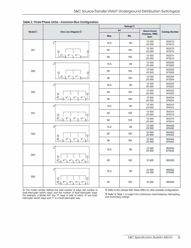
Table 2. Three-Phase Units—Common-Bus Configuration
Model① One-Line Diagram②
Ratings③
Catalog NumberkV Short-Circuit
Amperes, RMS, Sym.Max BIL
321
15.5 9512 50025 000
953212873212
29 12512 50025 000
953213873213
38 15012 50025 000
953214873214
330
15.5 9512 50025 000
953302873302
29 12512 50025 000
953303873303
38 15012 50025 000
953304873304
422
15.5 9512 50025 000
954222874222
29 12512 50025 000
954223874223
38 15012 50025 000
954224874224
431
15.5 9512 50025 000
954312874312
29 12512 50025 000
954313874313
38 15012 50025 000
954314874314
440
15.5 95 12 50025 000
954402874402
29 125 12 50025 000
954403874403
38 150 12 50025 000
954404874404
523
15.5 95 12 50025 000
955232875232
29 125 12 500 955233
550
15.5 95 12 50025 000
955502875502
29 125 12 500 955503
① The model number defines the total number of ways, the number of load-interrupter switch ways, and the number of fault-interrupter ways. For example, a Model 431 has “4” ways in total of which “3” are load-interrupter switch ways and “1” is a fault-interrupter way.
② Refer to the nearest S&C Sales Office for other possible configurations.
③ Refer to Table 1 on page 3 for continuous, load-dropping, interrupting, and momentary ratings.

S&C Source-Transfer Vista® Underground Distribution Switchgear
6 S&C Specification Bulletin 683-31
Table 3. Three-Phase Units—Split-Bus Configuration
Model① One-Line Diagram②
Ratings③
Catalog NumberkV Short-Circuit Amperes, RMS,
Sym.Max BIL
532
15.5 95 12 500 965322
29 125 12 500 965323
550
15.5 95 12 500 965502
29 125 12 500 965503
① The model number defines the total number of ways, the number of load-interrupter switch ways, and the number of fault-interrupter ways. For example, a Model 431 has “4” ways in total of which “3” are load- interrupter switch ways and “1” is a fault-interrupter way.
② Refer to the nearest S&C Sales Office for other possible configurations.③ Refer to Table 1 on page 3 for continuous, load-dropping, interrupting, and momentary ratings.
Table 4. Switchgear Styles
ItemSuffix to be Added
to Switchgear Catalog Number
Applicable to Models
UnderCover Style. Includes stainless steel tank, submersible wiring, and 25-foot (762 cm) submersible control cable for attachment to olive-green finish mild-steel low-voltage enclosure
-U
All models
Dry vault-mounted style. Includes mild-steel tank and 25-foot (762 cm) control cable for attachment to olive-green finish mild-steel low-voltage enclosure. Does not include submersible wiring
-V3
Wet vault-mounted style. Includes stainless steel tank, submersible wiring, and 25-foot (762 cm) submersible control cable for attachment to olive-green finish mild-steel low-voltage enclosure
-V4
Pad-mounted style. Includes pad-mounted enclosure for mounting switchgear with integral low-voltage compartment on a pad
Mild-steel outer enclosure and low-voltage compartment
Olive green finish -P6
Light gray finish -P11
Stainless steel outer enclosure and low-voltage compartment
Olive green finish -P16
Light gray finish -P21

S&C Specification Bulletin 683-31 7
S&C Source-Transfer Vista® Underground Distribution Switchgear
Table 5. Single-Pole or Three-Pole Fault Interrupting①②③
ItemSuffix to be Added
to Switchgear Catalog Number
Applicable to Models
Single-pole manual fault interrupter on all fault-interrupting ways -T012.5-kA-rated models with 1 or more fault interrupters
Three-pole manual fault interrupter on one fault-interrupting way (single-pole manual fault interrupter on all other fault-interrupting ways)
-T112.5-kA-rated models with 1 or more fault interrupters
Three-pole manual fault interrupter on two fault-interrupting ways (single-pole manual fault interrupter on all other fault-interrupting ways)
-T212.5-kA-rated models with 2 or more fault interrupters
Three-pole manual fault interrupter on three fault-interrupting ways (single-pole manual fault interrupter on all other fault-interrupting ways)
-T312.5-kA-rated models with 3 or more fault interrupters
① Not applicable to models rated 25 kA short circuit. All 25 kA-rated models include three-pole manual fault interrupters.
② Refer to the nearest S&C Sales Office for other possible configurations.
③ For standard models, components are in the following order (from left to right) when facing the operating side of the gear: load switches, bus taps, three-pole fault interrupters, single-pole fault interrupters.
Table 6. Voltage Transformers
System Voltage, kV① Transformer BIL, kV② Suffix to be Added to Switchgear Catalog Number
Applicable to Models
4.16 75 -X1
All models
7.2 75 -X2
8.32 75 -X3
12 95 -X4
12.47 95 -X4
13.8 95 -X5
14.4 95 -X5
23 125 -X6
24.9 125 -X6
27.6 125 -X7
34.5 150 -X8
① For additional system operating voltages and additional voltage- transformer ratings, refer to the nearest S&C Sales Office.
② The transformer BIL rating may impact the rating of the switchgear. The switchgear BIL rating will be de-rated to that of the transformer BIL rating if the latter is lower.
S&C Source-Transfer Vista® Underground Distribution Switchgear
8 S&C Specification Bulletin 683-31
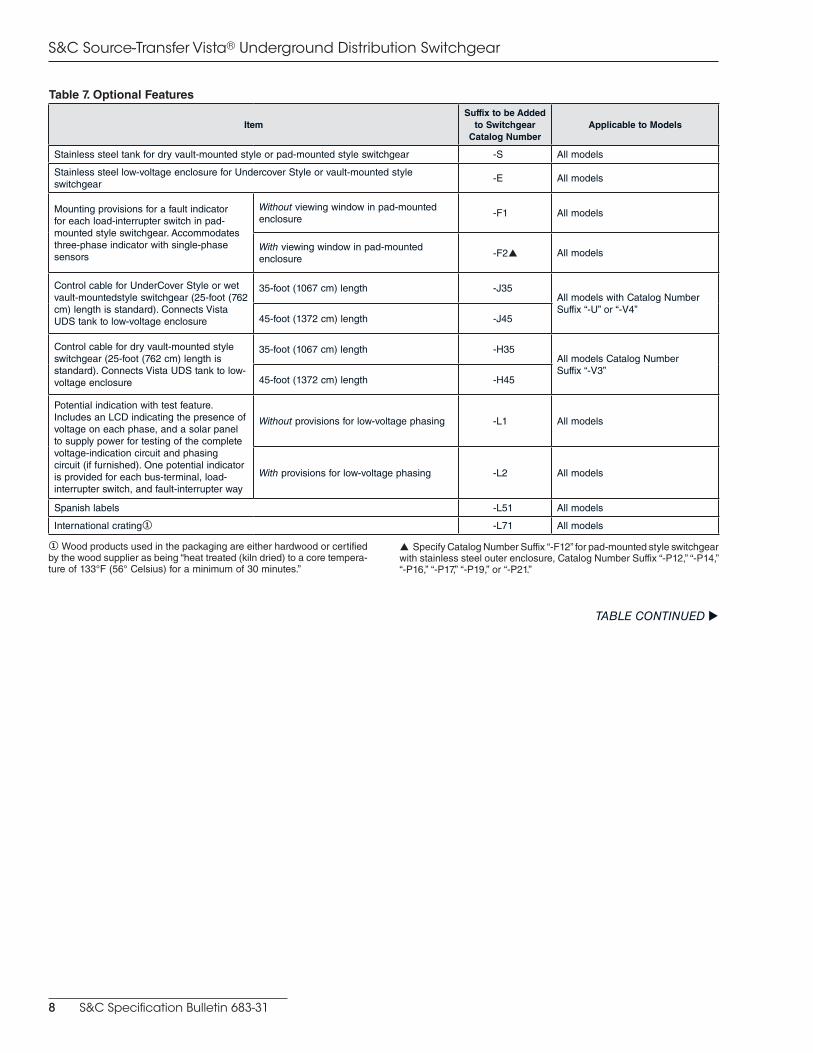
Table 7. Optional Features
ItemSuffix to be Added
to Switchgear Catalog Number
Applicable to Models
Stainless steel tank for dry vault-mounted style or pad-mounted style switchgear -S All models
Stainless steel low-voltage enclosure for Undercover Style or vault-mounted style switchgear
-E All models
Mounting provisions for a fault indicator for each load-interrupter switch in pad-mounted style switchgear. Accommodates three-phase indicator with single-phase sensors
Without viewing window in pad-mounted enclosure
-F1 All models
With viewing window in pad-mounted enclosure -F2p All models
Control cable for UnderCover Style or wet vault-mountedstyle switchgear (25-foot (762 cm) length is standard). Connects Vista UDS tank to low-voltage enclosure
35-foot (1067 cm) length -J35All models with Catalog Number Suffix “-U” or “-V4”
45-foot (1372 cm) length -J45
Control cable for dry vault-mounted style switchgear (25-foot (762 cm) length is standard). Connects Vista UDS tank to low-voltage enclosure
35-foot (1067 cm) length -H35All models Catalog Number Suffix “-V3”
45-foot (1372 cm) length -H45
Potential indication with test feature. Includes an LCD indicating the presence of voltage on each phase, and a solar panel to supply power for testing of the complete voltage-indication circuit and phasing circuit (if furnished). One potential indicator is provided for each bus-terminal, load-interrupter switch, and fault-interrupter way
Without provisions for low-voltage phasing -L1 All models
With provisions for low-voltage phasing -L2 All models
Spanish labels -L51 All models
International crating① -L71 All models
① Wood products used in the packaging are either hardwood or certified by the wood supplier as being “heat treated (kiln dried) to a core tempera-ture of 133°F (56° Celsius) for a minimum of 30 minutes.”
p Specify Catalog Number Suffix “-F12” for pad-mounted style switchgear with stainless steel outer enclosure, Catalog Number Suffix “-P12,” “-P14,” “-P16,” “-P17,” “-P19,” or “-P21.”
TABLE CONTINUED u

S&C Specification Bulletin 683-31 9
S&C Source-Transfer Vista® Underground Distribution Switchgear
Table 7. Optional Features—Continued
Item
Suffix to be Added
to Switchgear Catalog Number
Applicable to Models
900-ampere load-interrupter switch①②③ on
Way 1 -K1
All models rated 25 kA
Way 2 -K2
Way 3 -K3
Way 4 -K4
Way 5 -K5
Way 6 -K6
900-ampere fault interrupter①②③ on
Way 1 -Q1
Way 2 -Q2
Way 3 -Q3
Way 4 -Q4
Way 5 -Q5
Way 6 -Q6
600-A bushings without studs at the load-interrupter switch and bus terminals (in lieu of standard 600-A bushings with studs)
-M1
All models rated 12.5 kA
600-A④ bushings without studs, at the load-interrupter switch, fault interrupter, and bus terminals (in lieu of standard 600-A④ bushings with studs)
All models rated 25 kA
600-A bushings at fault-interrupter terminals (in lieu of 200-A bushing wells)
Without studs -M2All models rated 12.5 kA except Models 210, 320, 330, and 440
With studs -M3
200-A bushing wells at the load-interrupter switch and bus terminals (in lieu of 600-A bushings with studs)
-M4 All models rated 12.5 kA
Arc resistance for vault-mounted style (arc resistance is standard for UnderCover and pad-mounted styles), per IEC 298 Appendix AA, for arcs occurring internal to the tank (15 cycles, 12 kA symmetrical for 12.5 kA-rated models and 25 kA symmetrical for 25 kA-rated models)
-NAll models with Catalog Number Suffix “-V3” or “-V4”
Two-hole ground pads, one per way, located below the bushings or bushing wells (in lieu of standard one ground pad per tank)
-O All models
TABLE CONTINUED u
① 900-ampere cable connectors must be used.
② If piggybacked cable connectors are desired, refer to the nearest S&C Sales Office.③ Copper bus, Catalog Number Suffix “-Z5,” must be specified if 900-ampere load-interrupter switches and/or 900-ampere fault interrupters are specified.
④ Bushings are rated 900 amperes on ways furnished with 900-ampere load-interrupter switches (Catalog Number Suffix “-K1” through “-K6”) and/or 900-ampere fault interrupters (Catalog Number Suffix “-Q1” through “-Q6”).

S&C Source-Transfer Vista® Underground Distribution Switchgear
10 S&C Specification Bulletin 683-31
Table 7. Optional Features—Continued
ItemSuffix to be Added
to Switchgear Catalog Number
Applicable to Models
Remote low-pressure alarm. Includes internal contact for remote low-pressure indication, with wiring to outside of tank
With wires routed to low-voltage enclosure/compartment for customer connections
-R11All pad-mounted and dry-vault-mounted styles
-R12All UnderCover and wet vault-mounted styles
With wires routed to low-voltage enclosure/compartment furnished with a terminal block for customer connections
-R2All pad-mounted and dry vault-mounted styles
External trip provisions. Allows three-pole trip-ping of single-pole or three-pole fault interrupters via a trip signal from a remote location or an external relay. Requires a 110/120-Vac 50/60-Hz control power source①②
In addition to standard overcurrent control for all fault interrupters
-R31Pad-mounted and dry vault-mounted styles, Models 321, 422, 431, 523, 532
-R32UnderCover and wet vault-mount-ed styles, Models 321, 422, 431, 523, 532
In lieu of standard overcurrent control and current transformers for all fault interrupters
-R41Pad-mounted and dry vault-mounted styles, Models 321, 422, 431, 523, 532
-R42UnderCover and wet vault-mount-ed styles, Models 321, 422, 431, 523, 532
External trip provisions. Allows three-pole trip-ping of single-pole or three-pole fault interrupters via a trip signal from a remote location or an external relay. Requires a 220/240-Vac 50/60-Hz control power source①②
In addition to standard overcurrent control for all fault interrupters
-R33Pad-mounted and dry vault-mounted dtyles, Models 321, 422, 431, 523, 532
-R34UnderCover and wet vault-mount-ed styles, Models 321, 422, 431, 523, 532
In lieu of standard overcurrent control and current transformers for all fault interrupters
-R43Pad-mounted and dry vault-mounted styles, Models 321, 422, 431, 523, 532
-R44UnderCover and wet vault-mount-ed styles, Models 321, 422, 431, 523, 532
Overcurrent lockout. Includes three-phase current sensors on each source way-Y21
All pad-mounted and dry vault-mounted styles
-Y22All UnderCover and wet vault-mounted styles
Remote indication. Includes provisions for remote monitoring of the presence or absence of source voltages, manual or automatic operating mode, status of the Ready indicator, Event indicator, and overcurrent lockout (if feature is furnished)
-Y4
All models
Test panel. Permits the use of an external, adjustable three-phase source to verify, through independent measurement, the response of the control to loss of source, phase unbalance, and overcurrent lockout (if feature is furnished)
-Y5
Supervisory control. Permits switch operation from a remote location -Y6
Communications card. Permits local uploading of “events” and settings from the Micro-AT Control to a user-furnished personal computer as well as downloading of the user’s standard operating parameters
-Y8
Electrical antiparalleling. Prevents paralleling of two sources -Y10All common-bus configuration models
Copper bus③ -Z5 All models
① The external trip board can be powered by user-supplied 120-Vac 50/60-Hz control power source, 120 Vac 50/60 Hz supplied by a voltage transformer internal to the tank (option suffix “-X”) or 36 Vdc supplied by the battery charger.
② The user-supplied trip-initiating signal must be a momentary contact. Refer to the nearest S&C Sales Office if an application requires the use of a latching contact.③ Main bus can be rated up to 1200 amperes when Catalog Number Suffix “-Z5” is specified.

S&C Specification Bulletin 683-31 11
S&C Source-Transfer Vista® Underground Distribution Switchgear
Table 8. Accessories
Item Catalog Number
Shotgun clamp stick for use with separable connectors6-ft– 5½-in (197 cm) length 9933-150
8-ft– 5½-in (257 cm) length 9933-151
Storage bag for shotgun clamp stick, heavy canvas6-ft– 6-in (198 cm) length 9933-152
8-ft– 6-in (259 cm) length 9933-153
Test accessory. Permits preliminary checkout of source-transfer control using single-phase 120-volt ac source (before medium-voltage connections are made to the Vista UDS) to expedite full service once medium voltage is available TA-2669«
Overcurrent-control adapter cable. Required for programming overcurrent control
For connecting control to user-furnished personal computer in the field
For personal computers having 25-pin serial communication port
TA-2366
For personal computers having 9-pin serial communication port
TA-2367
For connecting control (removed from its enclosure) to user-furnished personal computer in the shop
For personal computers having 25-pin serial communication port
TA-2368
For personal computers having 9-pin serial communication port
TA-2369
Micro-AT Source-Transfer Control communications cable. For connecting optional communications card to user-furnished personal computer. Includes Matlink communication software
For personal computers having 25-pin serial communication port
TA-2320
For personal computers having 9-pin serial communication port
TA-2321
Portable motor operator. For operation of load-interrupter switches and single- or three-pole fault interrupters from a remote location. Includes carrying case, 50-foot (1524 cm) length control cable with remote controls, and power supplied by:
User-furnished 24-volt battery and battery charger
38320R1
S&C-furnished 24-volt battery and battery charger
38322R1
S&C-furnished ac input power supply 38323R1
Portable remote control for permanent motor operator. Requires one of the control cables listed below TA-2424
25-foot (762 cm) length control cable for portable remote control for permanent motor operator 9931-615
50-foot (1524 cm) length control cable for portable remote control for permanent motor operator 9931-616
Pentahead socket for ½ -inch drive 9931-074
« Catalog Number TA-2669 is only intended for use with Micro-AT Controls. Refer to the nearest S&C Sales Office for test accessories for use with Type AT Controls.
Table 10. Firmware Upgrade
Item Catalog Number
Firmware upgrade kit for Vista Overcurrent Control. Includes CD-ROM and instructions CUA-6895
Table 11. Touch-Up Kit Components—Aerosol Coatings in 12-ounce cans
Item Catalog Number
S&C light gray outdoor finish 9999-080
S&C olive green (Munsell 7GY3.29/1.5) outdoor finish 9999-058
S&C red-oxide primer 9999-061
Table 9. USB Cable Kit
Item Catalog Number
USB cable kit for connecting a personal computer to the Vista Overcurrent Control. Includes USB cable, adapter cable, driver CD-ROM, and installation instructions
TA-3153
S&C Source-Transfer Vista® Underground Distribution Switchgear
12 S&C Specification Bulletin 683-31
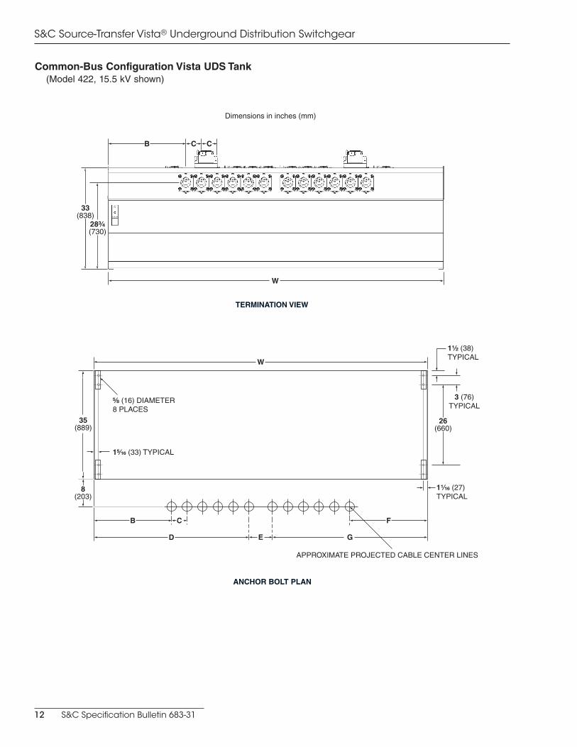
Common-Bus Configuration Vista UDS Tank (Model 422, 15.5 kV shown)
Dimensions in inches (mm)
TERMINATION VIEW
ANCHOR BOLT PLAN
W
35(889)
26(660)
8(203)
B F
D E G
⁵⁄₈ (16) DIAMETER8 PLACES
1¹⁄₁₆ (27)TYPICAL
1¹⁄₂ (38)TYPICAL
3 (76)TYPICAL
1⁵⁄₁₆ (33) TYPICAL
APPROXIMATE PROJECTED CABLE CENTER LINES
C
W
33(838)
28³⁄₄ (730)
B C C
S&C Specification Bulletin 683-31 13
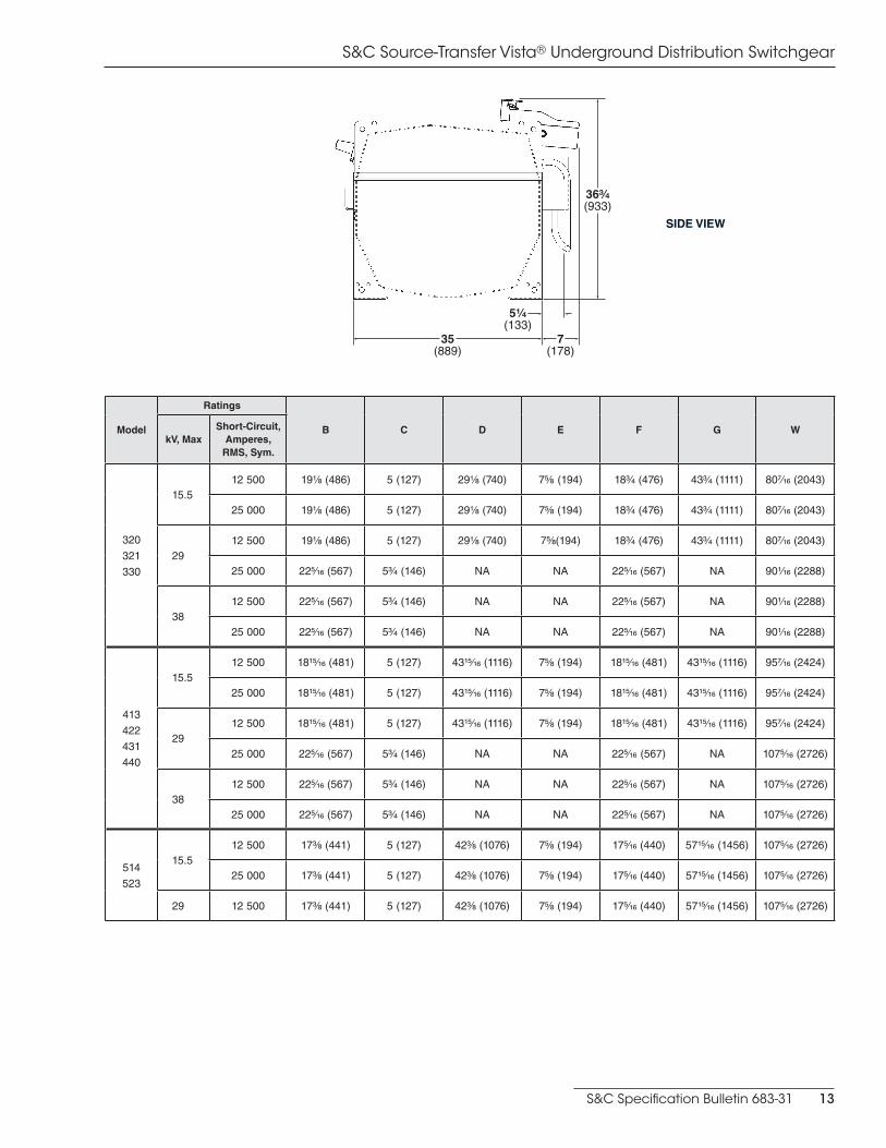
S&C Source-Transfer Vista® Underground Distribution Switchgear
Model
Ratings
B C D E F G WkV, Max
Short-Circuit, Amperes,
RMS, Sym.
320
321
330
15.512 500 19⅛ (486) 5 (127) 29⅛ (740) 7⅝ (194) 18¾ (476) 43¾ (1111) 807⁄16 (2043)
25 000 19⅛ (486) 5 (127) 29⅛ (740) 7⅝ (194) 18¾ (476) 43¾ (1111) 807⁄16 (2043)
2912 500 19⅛ (486) 5 (127) 29⅛ (740) 7⅝(194) 18¾ (476) 43¾ (1111) 807⁄16 (2043)
25 000 225∕16 (567) 5¾ (146) NA NA 225∕16 (567) NA 901∕16 (2288)
3812 500 225∕16 (567) 5¾ (146) NA NA 225∕16 (567) NA 901∕16 (2288)
25 000 225∕16 (567) 5¾ (146) NA NA 225∕16 (567) NA 901∕16 (2288)
413
422
431
440
15.512 500 1815⁄16 (481) 5 (127) 4315⁄16 (1116) 7⅝ (194) 1815⁄16 (481) 4315⁄16 (1116) 957⁄16 (2424)
25 000 1815⁄16 (481) 5 (127) 4315⁄16 (1116) 7⅝ (194) 1815⁄16 (481) 4315⁄16 (1116) 957⁄16 (2424)
2912 500 1815⁄16 (481) 5 (127) 4315⁄16 (1116) 7⅝ (194) 1815⁄16 (481) 4315⁄16 (1116) 957⁄16 (2424)
25 000 225∕16 (567) 5¾ (146) NA NA 225∕16 (567) NA 1075∕16 (2726)
3812 500 225∕16 (567) 5¾ (146) NA NA 225∕16 (567) NA 1075∕16 (2726)
25 000 225∕16 (567) 5¾ (146) NA NA 225∕16 (567) NA 1075∕16 (2726)
514
523
15.512 500 17⅜ (441) 5 (127) 42⅜ (1076) 7⅝ (194) 175∕16 (440) 5715⁄16 (1456) 1075∕16 (2726)
25 000 17⅜ (441) 5 (127) 42⅜ (1076) 7⅝ (194) 175∕16 (440) 5715⁄16 (1456) 1075∕16 (2726)
29 12 500 17⅜ (441) 5 (127) 42⅜ (1076) 7⅝ (194) 175∕16 (440) 5715⁄16 (1456) 1075∕16 (2726)
36³⁄₄(933)
7(178)
35(889)
5¹⁄₄(133)
SIDE VIEW
S&C Source-Transfer Vista® Underground Distribution Switchgear
14 S&C Specification Bulletin 683-31
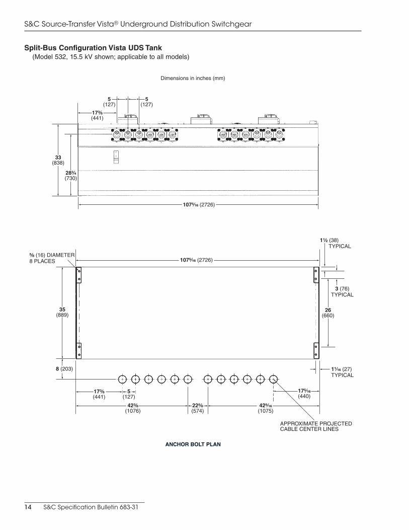
Split-Bus Configuration Vista UDS Tank(Model 532, 15.5 kV shown; applicable to all models)
Dimensions in inches (mm)
107⁵⁄₁₆ (2726)
42³⁄₈ (1076)
42⁵⁄₁₆ (1075)
22⁵⁄₈ (574)
17³⁄₈ (441)
5 (127)
17⁵⁄₁₆ (440)
1¹⁄₂ (38) TYPICAL
26(660)
1¹⁄₁₆ (27)TYPICAL
3 (76)TYPICAL
8 (203)
35 (889)
⁵⁄₈ (16) DIAMETER8 PLACES
APPROXIMATE PROJECTED CABLE CENTER LINES
ANCHOR BOLT PLAN
33(838)
28³⁄₄(730)
5(127)
5(127)
17³⁄₈(441)
107⁵⁄₁₆ (2726)
S&C Specification Bulletin 683-31 15
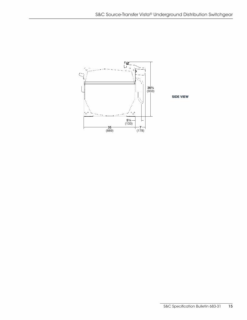
S&C Source-Transfer Vista® Underground Distribution Switchgear
36³⁄₄(933)
7(178)
35(889)
5¹⁄₄(133)
SIDE VIEW
S&C Source-Transfer Vista® Underground Distribution Switchgear
16 S&C Specification Bulletin 683-31
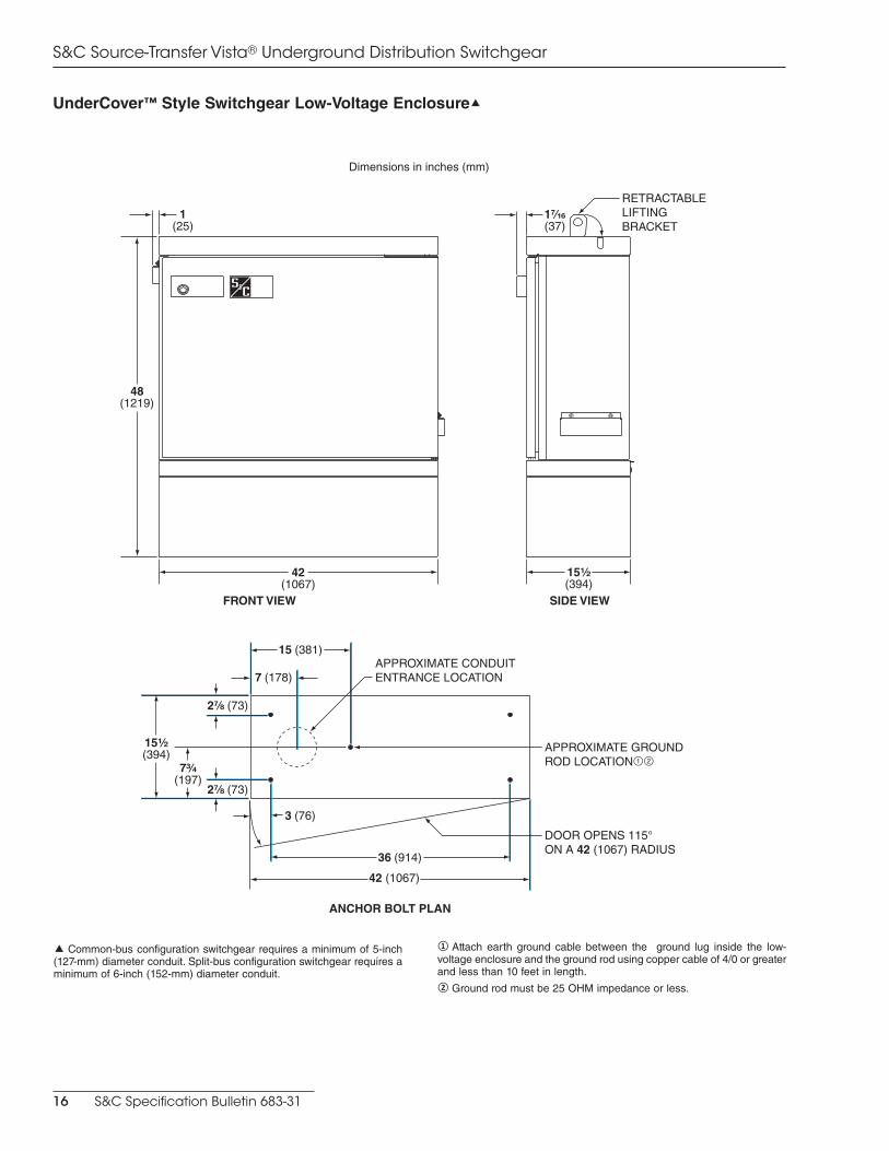
UnderCover™ Style Switchgear Low-Voltage Enclosure�
Dimensions in inches (mm)
7³⁄₄(197)
2⁷⁄₈ (73)
2⁷⁄₈ (73)
3 (76)
7 (178)
15¹⁄₂(394)
42 (1067)
36 (914)
15 (381)APPROXIMATE CONDUIT ENTRANCE LOCATION
DOOR OPENS 115°ON A 42 (1067) RADIUS
APPROXIMATE GROUND ROD LOCATION12
ANCHOR BOLT PLAN
42(1067)
15¹⁄₂(394)
48(1219)
1(25)
1⁷⁄₁₆(37)
RETRACTABLE LIFTING BRACKET
FRONT VIEW SIDE VIEW
� Common-bus configuration switchgear requires a minimum of 5-inch (127-mm) diameter conduit. Split-bus configuration switchgear requires a minimum of 6-inch (152-mm) diameter conduit.
① Attach earth ground cable between the ground lug inside the low-voltage enclosure and the ground rod using copper cable of 4/0 or greater and less than 10 feet in length.② Ground rod must be 25 OHM impedance or less.
S&C Specification Bulletin 683-31 17
S&C Source-Transfer Vista® Underground Distribution Switchgear
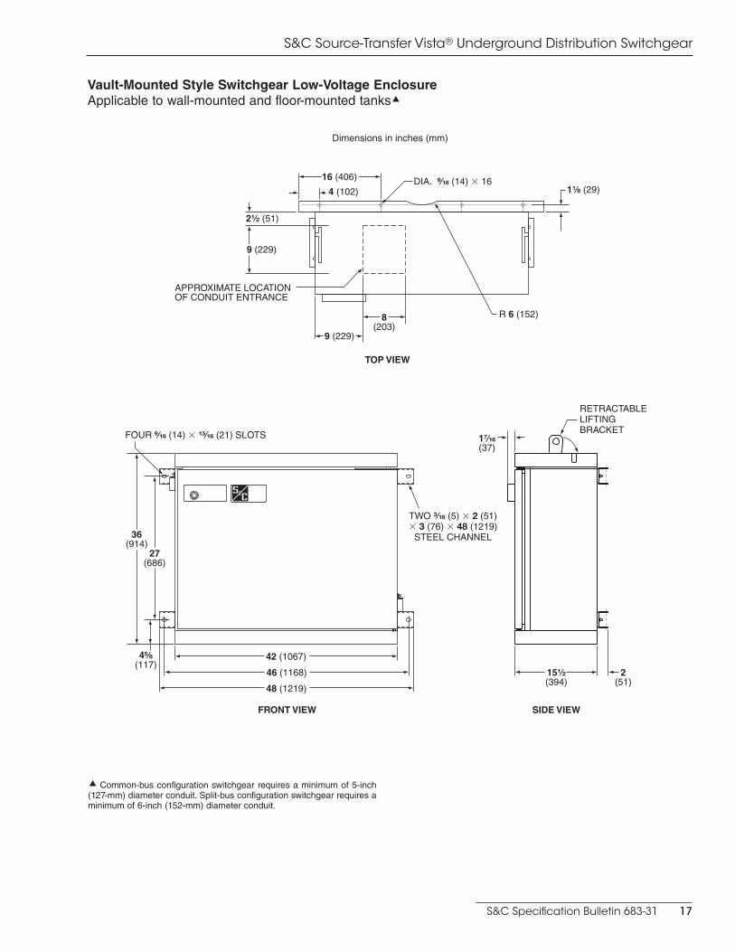
Vault-Mounted Style Switchgear Low-Voltage EnclosureApplicable to wall-mounted and floor-mounted tanks�
Dimensions in inches (mm)
� Common-bus configuration switchgear requires a minimum of 5-inch (127-mm) diameter conduit. Split-bus configuration switchgear requires a minimum of 6-inch (152-mm) diameter conduit.
FRONT VIEW
48 (1219)
42 (1067)
46 (1168)
4⁵�₈(117)
36(914)
27(686)
FOUR ⁹⁄₁₆ (14) � ¹³⁄₁₆ (21) SLOTS
TWO ³⁄₁₆ (5) � 2 (51) � 3 (76) � 48 (1219)
STEEL CHANNEL
SIDE VIEW
15¹⁄₂(394)
1⁷⁄₁₆(37)
2(51)
RETRACTABLE LIFTING BRACKET
2¹⁄₂ (51)
4 (102)
9 (229)
9 (229)
16 (406)
APPROXIMATE LOCATIONOF CONDUIT ENTRANCE
1¹⁄₈ (29)DIA. ⁹⁄₁₆ (14) � 16
R 6 (152)8(203)
TOP VIEW

S&C Source-Transfer Vista® Underground Distribution Switchgear
18 S&C Specification Bulletin 683-31
Model
Ratings
D F G HkV, Max
Short-Circuit,
Amperes, RMS, Sym.
321
330
15.512 500 61 (1549) 7⅝ (194) 38⅞ (987) 5 (127)
25 000 65 (1651) 7⅝ (194) 38⅞ (987) 5 (127)
2912 500 65 (1651) 7⅝ (194) 38⅞ (987) 5 (127)
25 000 65 (1651) NA NA 5¾ (146)
3812 500 65 (1651) NA NA 5¾ (146)
25 000 65 (1651) NA NA 5¾ (146)
422
431
440
15.512 500 61 (1549) 7⅝ (194) 473⁄16 (1199) 5 (127)
25 000 65 (1651) 7⅝ (194) 473⁄16 (1199) 5 (127)
2912 500 65 (1651) 7⅝ (194) 473⁄16 (1199) 5 (127)
25 000 65 (1651) NA NA 5¾ (146)
3812 500 65 (1651) NA NA 5¾ (146)
25 000 65 (1651) NA NA 5¾ (146)
523
550
15.512 500 65 (1651) 22⅝ (575) 45¼ (1149) 5 (127)
25 000 65 (1651) 22⅝ (575) 45¼ (1149) 5 (127)
29 12 500 65 (1651) 22⅝ (575) 45¼ (1149) 5 (127)
TERMINATION VIEW
Common-Bus Configuration Pad-Mounted Style Switchgear with Low-Voltage Enclosure(Model 422, 15.5 kV shown)
Dimensions in inches (mm)
W
P
5 (127)
34⅞ (886)
36 (914)
2⅜ (60)
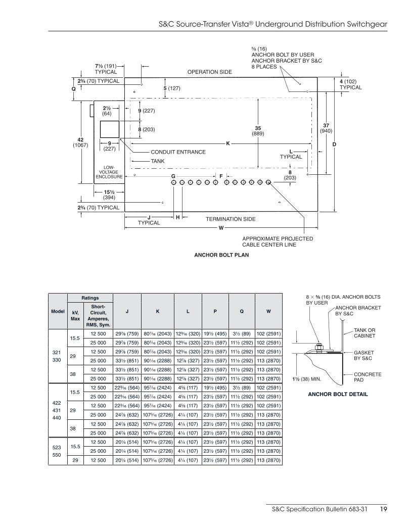
S&C Specification Bulletin 683-31 19
S&C Source-Transfer Vista® Underground Distribution Switchgear
W
TERMINATION SIDE
OPERATION SIDE
JTYPICAL
H
LTYPICAL
APPROXIMATE PROJECTEDCABLE CENTER LINE
2³⁄₄ (70) TYPICAL
15¹⁄₂ (394)
2¹⁄₂ (64)
7¹⁄₂ (191) TYPICAL
4 (102) TYPICAL
9 (227)
42 (1067)
35 (889)
37 (940)
D
2³⁄₄ (70) TYPICAL
8 (203)
9 (227)
5 (127)Q
CONDUIT ENTRANCE
TANK
⁵⁄₈ (16)ANCHOR BOLT BY USERANCHOR BRACKET BY S&C8 PLACES
LOW-VOLTAGE
ENCLOSURE G F
K
8 (203)
ANCHOR BOLT PLAN
8 � ⁵⁄₈ (16) DIA. ANCHOR BOLTSBY USER
1¹⁄₂ (38) MIN.
ANCHOR BRACKETBY S&C
TANK OR CABINET
GASKETBY S&C
CONCRETE PAD
ANCHOR BOLT DETAIL
Model
Ratings
J K L P Q WkV, Max
Short-Circuit,
Amperes, RMS, Sym.
321
330
15.512 500 29⅞ (759) 807⁄16 (2043) 123⁄16 (320) 19½ (495) 3½ (89) 102 (2591)
25 000 29⅞ (759) 807⁄16 (2043) 123⁄16 (320) 23½ (597) 11½ (292) 102 (2591)
2912 500 29⅞ (759) 807⁄16 (2043) 123⁄16 (320) 23½ (597) 11½ (292) 102 (2591)
25 000 33½ (851) 901∕16 (2288) 12⅞ (327) 23½ (597) 11½ (292) 113 (2870)
3812 500 33½ (851) 901∕16 (2288) 12⅞ (327) 23½ (597) 11½ (292) 113 (2870)
25 000 33½ (851) 901∕16 (2288) 12⅞ (327) 23½ (597) 11½ (292) 113 (2870)
422
431
440
15.512 500 223⁄16 (564) 957⁄16 (2424) 4⅝ (117) 19½ (495) 3½ (89) 102 (2591)
25 000 223⁄16 (564) 957⁄16 (2424) 4⅝ (117) 23½ (597) 11½ (292) 102 (2591)
2912 500 223⁄16 (564) 957⁄16 (2424) 4⅝ (117) 23½ (597) 11½ (292) 102 (2591)
25 000 24⅞ (632) 1075∕16 (2726) 4¼ (107) 23½ (597) 11½ (292) 113 (2870)
3812 500 24⅞ (632) 1075∕16 (2726) 4¼ (107) 23½ (597) 11½ (292) 113 (2870)
25 000 24⅞ (632) 1075∕16 (2726) 4¼ (107) 23½ (597) 11½ (292) 113 (2870)
523
550
15.512 500 20¼ (514) 1075∕16 (2726) 4¼ (107) 23½ (597) 11½ (292) 113 (2870)
25 000 20¼ (514) 1075∕16 (2726) 4¼ (107) 23½ (597) 11½ (292) 113 (2870)
29 12 500 20¼ (514) 1075∕16 (2726) 4¼ (107) 23½ (597) 11½ (292) 113 (2870)

S&C Source-Transfer Vista® Underground Distribution Switchgear
20 S&C Specification Bulletin 683-31
SIDE VIEW
Split-Bus Configuration Pad-Mounted Style Switchgear with Low-Voltage Enclosure(Model 532, 15.5 kV shown; applicable to all models)
Dimensions in inches (mm)
SIDE VIEW
36 (914)
2⅜ (60)
113 (2870)
23½ (597)
34⅞ (886)
43 (1092)
65 (1651)
5 (127)
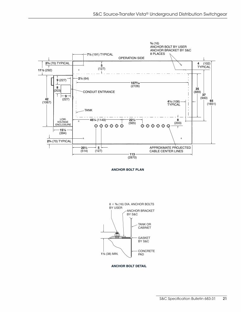
S&C Specification Bulletin 683-31 21
S&C Source-Transfer Vista® Underground Distribution Switchgear
5(127)
20¹⁄₄(514)
2³⁄₄ (70) TYPICAL
22¹⁄₄(565)
45¹⁄₄ (1149)
113(2870)
107⁵⁄₁₆(2726)
APPROXIMATE PROJECTEDCABLE CENTER LINES
15¹⁄₄(394)
4¹⁄₄ (108)TYPICAL
11¹⁄₂ (292)
2³⁄₄ (70) TYPICAL
LOW-VOLTAGE
ENCLOSURE
35(889)
5(127)
42(1067)
7¹⁄₂ (191) TYPICAL
⁵⁄₈ (16)ANCHOR BOLT BY USERANCHOR BRACKET BY S&C8 PLACES
OPERATION SIDE
4 (102)TYPICAL
37(940)
8(203)
65(1651)
TANK
CONDUIT ENTRANCE8
(203)
9 (227)
9(227)
2¹⁄₂ (64)
ANCHOR BOLT PLAN
8 � ⁵⁄₈ (16) DIA. ANCHOR BOLTSBY USER
1¹⁄₂ (38) MIN.
ANCHOR BRACKETBY S&C
TANK OR CABINET
GASKETBY S&C
CONCRETE PAD
ANCHOR BOLT DETAIL


