specifically, today’s talk will cover - agilent educational seminar discusses creating, measuring,...
TRANSCRIPT

This educational seminar discusses creating, measuring, and
troubleshooting High Vacuum (≈ 10-4 10-8 Torr) systems.
Specifically, today’s talk will cover: • Brief review of Rough Vacuum (Characteristics,
Pumps & Gauges)
• Applications requiring High Vacuum
• High Vacuum Gauges & Pumps
• Troubleshooting High Vacuum applications
• High Vacuum summary and preview of Ultra-High Vacuum Webinar
Previous Webinars (Vacuum Fundamentals and Rough
Vacuum) are available for download at:
http://www.agilent.com/en-us/training-events/eseminars/vacuum

Rough Vacuum Review: Characteristics
Particles are moving in Viscous Flow
• Short Mean Free Path (MFP)
• Many more collisions with each other than with chamber walls
• Particles are ‘motivated’ to enter vacuum pumps!
Factors governing pumpdown time:
• Dimensions of the chamber & capacity of the rough vacuum pumps (Volume Pumping)
• Chamber surface conditions (Desorption)
• Gas composition 80% N2 - 20% O2
down to about 18 Torr, then mostly H2O down to 10-3 Torr Time
Desorption
Pre
ssu
re (
To
rr)
Volume
10+3
10-0
10-3

Rough Vacuum Review: Pumps and Gauges
Rough Vacuum PUMPS require molecules to be in Viscous Flow for effective pumping
• Characterized by their:
a) Capacity (Pumping Speed)
b) Pumping Fluid (Oil Sealed or Oil Free)
c) Base Pressure (Singe or Dual Stage)
Rough Vacuum GAUGES rely on Mechanical Force (Bourdon, Capacitance Manometer) or Thermal Conductivity (Convection, Thermocouple, Pirani) to measure pressure
• Characterized by their:
a) Accuracy
b) Response Time
c) Cost 10-6 10-4 10-2 1 10+2
Pressure (Torr)
Rough Vacuum High Vacuum
Thermocouple Gauge
Bourdon Gauge
Capacitance Manometer
Pirani Gauge

The Range of Vacuum Pressure
760 Torr 25 Torr 7.5 e-4 Torr 7.5 e-7 Torr 7.5 e-10 Torr 7.5 e-12 Torr
Mass Spectrometry
Semiconductors Pick-up &
Conveyance Food
Packaging
Incandescent
Lamps
Freeze
Drying
Heat
Treatment
Surface
Coating
Thin Film
Deposition
Electron
Microscopy
Nanotechnology Sub-Atomic
Research
Space
Research
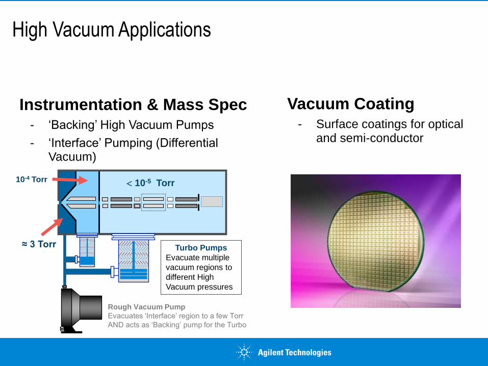
High Vacuum Applications
Instrumentation & Mass Spec - ‘Backing’ High Vacuum Pumps
- ‘Interface’ Pumping (Differential Vacuum)
Vacuum Coating - Surface coatings for optical
and semi-conductor
Rough Vacuum Pump
Evacuates ‘Interface’ region to a few Torr
AND acts as ‘Backing’ pump for the Turbo
10-4 Torr 10-5 Torr
≈ 3 Torr Turbo Pumps
Evacuate multiple
vacuum regions to
different High
Vacuum pressures

Rough Vacuum Applications
High Vacuum Furnaces - Sealing and Soldering processes
requiring ultra-low levels of moisture and residual gas
X-Ray Tubes - Moisture removal and vacuum
brazing

Characteristic of High Vacuum
February 9, 2017
Confidentiality Label
7
• Gases originate from walls & surfaces
• Gases are in Molecular Flow (MFP > Chamber Dimensions)
• Gases move randomly at the Speed of Sound
• Surface Area, Material Type and Pump Speed determine ultimate pressure and pumpdown times (desorption and diffusion)
• Gas Composition is constant through High Vacuum (80% H2O, 10% N2, 10% CO)
Volume
Time
Desorption
Diffusion
Pressure Decay
Pre
ssu
re (
To
rr)
10+3
10-0
10-3
10-6
10-9

RANGE GAUGE TYPE EXAMPLES
Rough Vacuum
Atm - 10-3 Mechanical Deflection & Thermal Transfer Gauges
Bourdon Gauge Capacitance Manometer Thermocouple, Convection, Pirani
High Vacuum
10-3 - 10-9
Mechanical Deflection & Ionization Gauges
Capacitance Manometer Hot Filament Gauge (BAG) IMG / Penning Gauge
Ultra High Vacuum
< 10-10 Ionization Gauges & Gas Analyzers
UHV Ionization Gauges Ion Pump Current Residual Gas Analyzer (RGA)
Vacuum Measurement Technologies
- Different technologies are required to measure the vacuum
pressure in different vacuum regions
https://cds.cern.ch/record/455555/files/p75.pdf

High Vacuum Gauges
February 9, 2017
Confidentiality Label
9
10-12 10-10 10-8 10-6 10-4 10-2 1 10+2
Pressure (Torr)
Rough Vacuum High Vacuum Ultra-High
Vacuum
Bourdon Gauge
Hot Fil. Ion Gauge
IMG / Penning Gauge
Thermocouple Gauge
Pirani Gauge
Capacitance Manometer
Residual Gas Analyzer
Spinning Rotor Gauge

e- electron
neutral gas atom
e-
e-
e-
Grid
Ion Collector Filament
Electrons Collide with Neutral Atoms or Molecules
e-
Controller
Hot Filament Ion Gauge
How it Works: • Photo-electrons emitted by the filament are accelerated towards the spiral grid and strike
‘background’ gas molecules – creating ions
• Ions are accelerated towards the central collector – resulting current is directly proportional to the gas density (pressure!)
Characteristics: • Gas Type Dependent (reading varies with gas species)
• Accuracy: ± 50% (typical)
• 10-2 to 10-9 Torr Operating Range
February 9, 2017
Confidentiality Label
10
Electron Energy (eV)
Ion
iza
tio
n P
rob
ab
ility
Gas
Relative
Sensitivity
Ar 1.2
CO 1.0 – 1.1
H2 0.40 - 0.55
He 0.16
H20 0.9 – 1.0
N2 1.00
Ne 0.25
O2 0.8 – 0.9 0 50 10
015
020
025
030
0
He
Ne
H2
N2
O2
Ar
Cold Cathode Gauge
February 9, 2017
Confidentiality Label
11
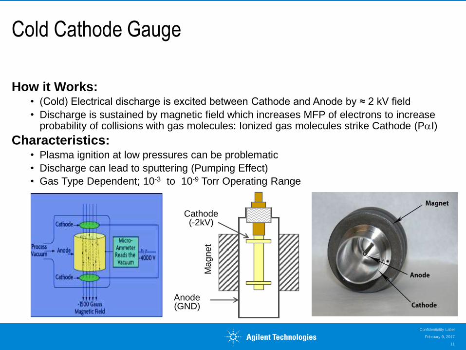
How it Works: • (Cold) Electrical discharge is excited between Cathode and Anode by ≈ 2 kV field
• Discharge is sustained by magnetic field which increases MFP of electrons to increase probability of collisions with gas molecules: Ionized gas molecules strike Cathode (PI)
Characteristics: • Plasma ignition at low pressures can be problematic
• Discharge can lead to sputtering (Pumping Effect)
• Gas Type Dependent; 10-3 to 10-9 Torr Operating Range
Anode (GND)
Cathode (-2kV)
Magn
et

Inverted Magnetron (IMG) Gauge
February 9, 2017
Confidentiality Label
12
How it Works: • Improvements to Cold Cathode (Penning) design made by Hobson & Redhead (1950’s)
- Guard rings at cathode potential improve plasma containment
- Higher voltage improves probability of plasma ignition
- Magnetic field parallel to anode axis
Characteristics: • Improved ability to ignite and sustain a STABLE plasma
• 10-3 to 10-11 Torr Operating Range (HV & UHV Gauge) High Voltage Connection to Anode (+4 kV)
Cylindrical
Magnet
Cathode and Electrometer Connection to
Ground
To Vacuum Chamber

Combination (‘Wide-Range’) Gauges
How They Work: • Multiple (complimentary) gauge technologies combined in single housing: NO NEW
PHYSICS!
IMG & Pirani
BAG & Pirani
Pirani & Cap
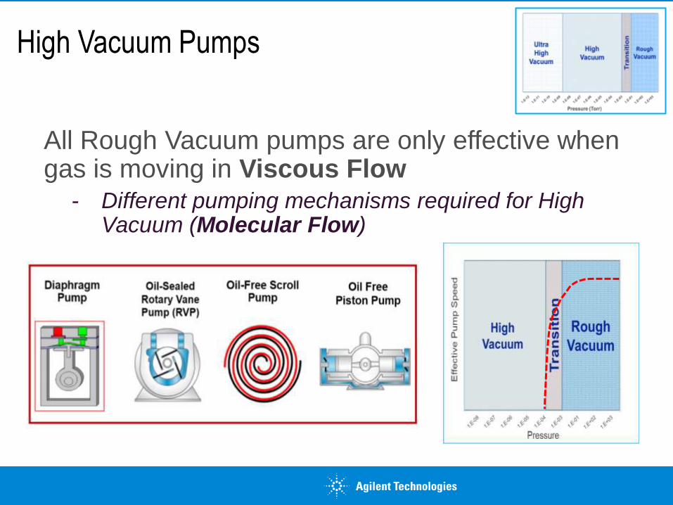
High Vacuum Pumps
All Rough Vacuum pumps are only effective when gas is moving in Viscous Flow
- Different pumping mechanisms required for High Vacuum (Molecular Flow)

High Vacuum Pump Operating Range
February 9, 2017
Confidentiality Label
15
P (Torr)
10-12 10-10 10-8 10-6 10-4 10-2 1 10+2
Turbo Pump
Vapor Jet Pump
Cryo Pump
Drag Pump
LN2 Trap
Rough Vacuum High Vacuum Ultra-High
Vacuum

High Vacuum Pump Operating Range
February 9, 2017
Confidentiality Label
16
P (Torr)
10-12 10-10 10-8 10-6 10-4 10-2 1 10+2
Turbo Pump
Vapor Jet Pump
Cryo Pump
Drag Pump
LN2 Trap
Rough Vacuum High Vacuum Ultra-High
Vacuum

High Vacuum Pumps
Displacement Pumps Capture Pumps
High Vacuum pumps are described as either Displacement or Capture pumps

Turbo-Molecular Pump
February 9, 2017
Confidentiality Label
18
How it Works: • Rotating Blades strike gas molecule entering the pump in Molecular Flow
• Non-rotating Stators (complementary blade angle) reflect the molecule towards exhaust
- Increasing blade pitch prevents the molecule from travelling backwards towards the vacuum chamber
• Drag Stage uses momentum transfer to compress gas to higher exhaust pressure
Rotating Blades
Inlet Flange
Purge/
Vent Port
Electric Motor
Drag Stage Foreline
(Exhaust)
Connection
Non-Rotating
Stators
Suspension (Bearings)
Molecular
Drag Stage

Turbo-Molecular Pump
February 9, 2017
Confidentiality Label
19
How it Works: • Rotating Blades strike gas molecule entering the pump in Molecular Flow
• Non-rotating Stators (complementary blade angle) reflect the molecule towards exhaust
- Increasing blade pitch prevents the molecule from travelling backwards towards the vacuum chamber
• Drag Stage uses momentum transfer to compress gas to higher exhaust pressure
Suspension (Bearings)
Molecular
Drag Stage
Rotating Blades
Inlet Flange
Purge/
Vent Port
Electric Motor
Drag Stage Foreline
(Exhaust)
Connection
Non-Rotating
Stators

Turbo-Molecular Pump: Molecular Drag
February 9, 2017
Confidentiality Label
20
How it Works: • Rotating blade design can only compress gas to ≈ 10-3 Torr (max) and result in poor
pumping speeds for light gases
• Molecular Drag Stage transfers momentum to particles during residence time on a rotating element and directs the motion in a confined channel
• Gaede (‘MacroTorr’), Holweck, and Siegbahn (‘TwisTorr’) Designs
Drum Rotor
Impeller
Helical Groove
Channel
Disk Rotor
Impeller
Channel
Stripper
Surface
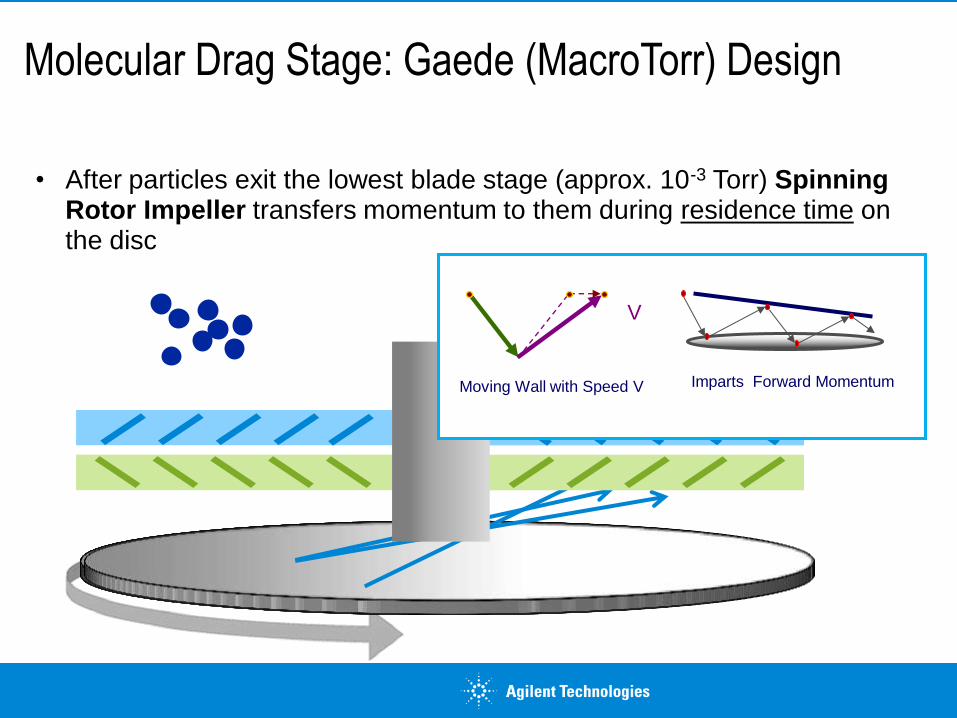
Molecular Drag Stage: Gaede (MacroTorr) Design
• After particles exit the lowest blade stage (approx. 10-3 Torr) Spinning Rotor Impeller transfers momentum to them during residence time on the disc
V
Moving Wall with Speed V Imparts Forward Momentum

• Stripper directs particles from upper stage to lower stage: compressing gas ≈ 10,000x (10-3 to 10 Torr)
• BENEFITS: • MUCH greater pumping speeds for light gases
• SMALLER (less expensive) backing pumps required to compress gas to atmosphere
Molecular Drag: MacroTorr Design (cont’d)

Vapor Jet (‘Diffusion”) Pump
February 9, 2017
Confidentiality Label
23
How it Works: • Heating Element vaporizes oil from the Reservoir forcing it up the Jet Stack; Oil
ejected at ≈ 330 m/s (750 mph)
• Fine mist of oil strikes gas molecules entering the pump (momentum transfer) moving particles ‘down’ and towards the pump’s Water Cooled Body
- Oil mist and gas condense at the cooled wall of the pump and continue moving towards pump exhaust
• Multiple oil mist ‘Curtains’ prevent molecules from travelling back towards pump Inlet
Cold Cap
Jet Stack (Multistage)
Inlet Water-
Cooled Body
Exhaust
Baffles
Foreline
Electrical Connector
Heater Element
Oil Reservoir (Boiler)

Diffusion Pump Performance
February 9, 2017
Confidentiality Label
24
Pump Speed 12 l/s to 50,000
l/s
Ultimate Vacuum 3 x 10⁻³ to
1 x 10⁻⁹ Torr
Price $800 - $30K
Oil Capacity 55 cm3 - 3 gal
Cooling Method air, water
Back-streaming may require
cold trap

Principle of Operation
February 9, 2017
Confidentiality Label
25
Vapor Molecules accelerated at 750 MPH
Oil warm-up time: Few mins. to 1hr
Gases compressed
at each stage
Fluid Vapor Jet
Gas Molecules
Water Cooling Coils

Diffusion Pump: Limiting Release of Vapors
February 9, 2017
Confidentiality Label
26
Foreline Baffle
Cooled to Condense
Oil Vapors
Kept Hot to Release Trapped Gases
From Condensed Oil

Maximum Tolerable Foreline Pressure Exceeded
February 9, 2017
Confidentiality Label
27
Foreline Pressure too High
Backstreaming

Cryogenic Pump
February 9, 2017
Confidentiality Label
28
How it Works: • Liquid He cooling circuit maintains 1st Stage Frontal Array’ at < 100K: Water
• 2nd Stage Cryo-array maintained at < 20K to ‘trap’ Argon, Nitrogen, Oxygen etc
- Activated charcoal attached to 2nd Stage forms labyrinth to ‘temporarily detain’ fast moving H2 and He gases
• Requires Rough Vacuum Pump to generate ‘Insulating Vacuum’ so Cryo system can maintain cold head temperatures
Characteristics: • Highest Pumping speed for H2O
• Requires periodic re-generation (heating to room temperature) to remove trapped gases
Expander Module
2nd Stage Cryo-array
Regeneration Purge Tube
Remote Temperature
Sensor
1st Stage Can
Pressure Relief Valve
1st Stage Frontal Array
Pump Body
Pump speed 800 l/s to
60000 l/s
Ultimate Vacuum 1 x 10⁻³ to
1 x 10⁻¹⁰ Torr
Price $4K - $60K
Capacity 270 to 9000 T/I
Regen
Method
Hot Gas or
Electric
Second Stage
Activated Charcoal

Cryo-Pump Regeneration
February 9, 2017
Confidentiality Label
29
• Warm the cryopump to room temperature (290K - 300K) using heated dry nitrogen
• Rough the pump to approximately 50 millitorr
• Perform rate-of-rise test per manufacturer specification
• Rough vacuum system (insulating vacuum) then Chill pump to operating temperature

High Vacuum Pump Comparison
Type Advantages Disadvantages
Turbo-Molecular Pump
(w/ drag stage)
Low ultimate pressure Fast start-up & recovery Clean Continuous pumping Small forepump required No Oil!
Mechanical bearing Some Noise & Vibration Lower pump speed H2 & He
Vapor Jet (Diffusion) Pump
High Throughput Lowest cost per L/sec No moving parts Low Maintenance Pumps all gasses
Backstreaming No pressure tolerance Requires water cooling May require cold trap Vertical installation only No operator feedback
Cryogenic (Capture) Pump
Highest H2O pumping speed Mounts any position Clean (Oil-Free) Continuous Mechanical
pumping not required
Regeneration required Affected by heat Not for hazardous gases Low frequency vibration

Crossover Pressure: Rough to High Vacuum
BOOSTERS: ROOTS & Claw Pumps • Optimal pumping speed in TRANSITION REGION
Rough
Vacuum
`
High
Vacuum
Tra
nsit
ion
High
Vacuum
Pu
mp
ing
Sp
eed
10 00
100
10
1

Troubleshooting High Vacuum Systems
Permeation &
Process Gas
Time
Volume
Diffusion
Desorption
Pressure Decay
Pre
ss
ure
(To
rr)
10+3
10-0
10-3
10-6
10-9

February 9, 2017
Confidentiality Label
33
Troubleshooting High Vacuum Systems
Permeation (He, H2)
Outgassing (H2O, Solvents)
Backstreaming
(Oil, He)
Internal
Leaks Real
Leaks
Virtual
Leaks
Diffusion (H2)
Surface Conditions &
Trapped Volumes:
Materials: Leaks: Desorption
Real Leaks
Back-
streaming
Diffusion
Virtual
Leaks
Permeation
Process
SD
High Vacuum
Pumping Speed
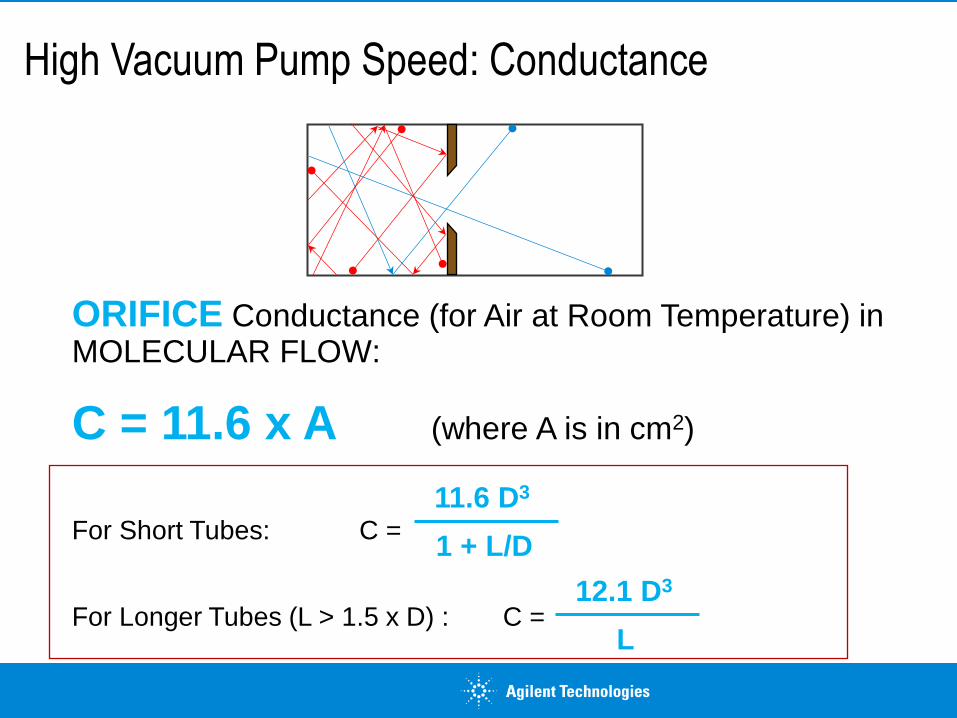
High Vacuum Pump Speed: Conductance
ORIFICE Conductance (for Air at Room Temperature) in MOLECULAR FLOW:
C = 11.6 x A (where A is in cm2)
For Short Tubes: C =
For Longer Tubes (L > 1.5 x D) : C =
11.6 D3
1 + L/D
12.1 D3
L
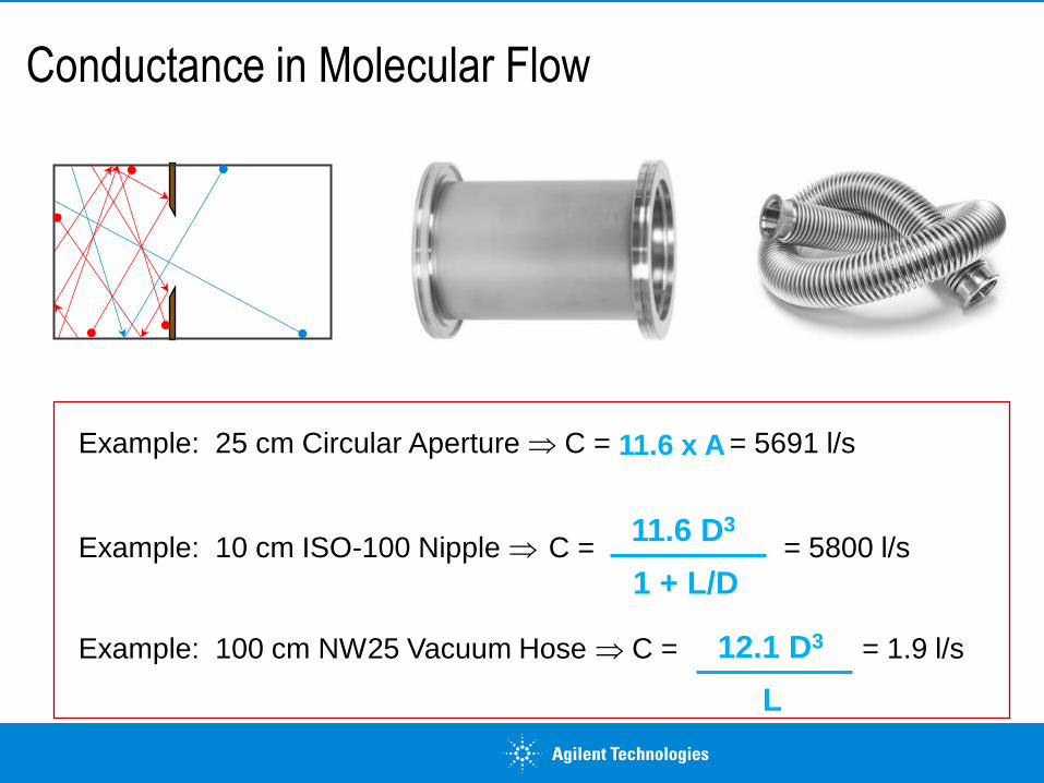
Conductance in Molecular Flow
Example: 25 cm Circular Aperture C = = 5691 l/s
Example: 10 cm ISO-100 Nipple C = = 5800 l/s
Example: 100 cm NW25 Vacuum Hose C = = 1.9 l/s
11.6 D3
1 + L/D
12.1 D3
L
11.6 x A

February 9, 2017
Confidentiality Label
36
1 10-7
10-6
10-5
10-4 P
ressu
re (
To
rr)
10 100 1000
Time (min)
6 2 4 6 8 2 4 8 2 4 6 8
2
4 6
8
2
4 6
8
2
4 6
8
Document Vacuum System Performance!
SHAPE of pumpdown curve stays the same: Check for Decrease in
Pump Performance
As system is used, pumpdown time becomes longer
February 9, 2017
Confidentiality Label
37
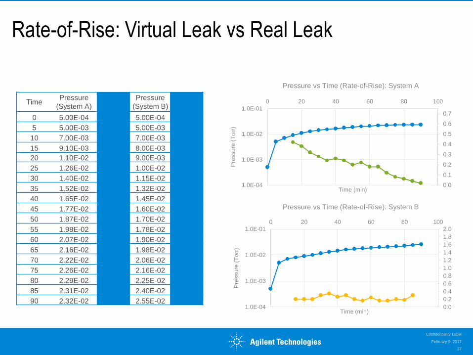
Rate-of-Rise: Virtual Leak vs Real Leak
Time Pressure
(System A) Rate of
Rise Pressure
(System B) Rate of
Rise
0 5.00E-04 5.00E-04
5 5.00E-03 5.00E-03
10 7.00E-03 7.00E-03
15 9.10E-03 0.42 8.00E-03 0.20
20 1.10E-02 0.38 9.00E-03 0.20
25 1.26E-02 0.32 1.00E-02 0.20
30 1.40E-02 0.28 1.15E-02 0.30
35 1.52E-02 0.24 1.32E-02 0.34
40 1.65E-02 0.26 1.45E-02 0.26
45 1.77E-02 0.24 1.60E-02 0.30
50 1.87E-02 0.20 1.70E-02 0.20
55 1.98E-02 0.22 1.78E-02 0.16
60 2.07E-02 0.18 1.90E-02 0.24
65 2.16E-02 0.18 1.98E-02 0.16
70 2.22E-02 0.12 2.06E-02 0.16
75 2.26E-02 0.08 2.16E-02 0.20
80 2.29E-02 0.06 2.25E-02 0.18
85 2.31E-02 0.04 2.40E-02 0.30
90 2.32E-02 0.02 2.55E-02 0.30 0.0
0.2
0.4
0.6
0.8
1.0
1.2
1.4
1.6
1.8
2.0
1.0E-04
1.0E-03
1.0E-02
1.0E-01
0 20 40 60 80 100
Pre
ssure
(T
orr
)
Time (min)
Pressure vs Time (Rate-of-Rise): System B
0.0
0.1
0.2
0.3
0.4
0.5
0.6
0.7
1.0E-04
1.0E-03
1.0E-02
1.0E-01
0 20 40 60 80 100
Pre
ssure
(T
orr
)
Time (min)
Pressure vs Time (Rate-of-Rise): System A

Troubleshooting High Vacuum Pumpdown
Time (min)
0 5 15 25 10 20 30
Pre
ssure
(Torr
)
P
T
Monitoring the CHANGE in Pressure over Time can help to determine if there is a leak in the vacuum system
• A vacuum system with OUTGASSING issues will display a fairly constant rate of decrease in pressure over time
Outgassing
10+2
10-1
10-3
10-5
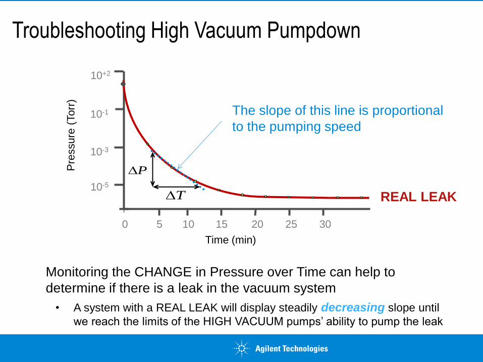
Troubleshooting High Vacuum Pumpdown
Monitoring the CHANGE in Pressure over Time can help to
determine if there is a leak in the vacuum system
• A system with a REAL LEAK will display steadily decreasing slope until
we reach the limits of the HIGH VACUUM pumps’ ability to pump the leak
The slope of this line is proportional
to the pumping speed
REAL LEAK
Time (min)
0 5 15 25 10 20 30
Pre
ssure
(Torr
) 10+2
10-1
10-3
P
T10-5

February 9, 2017
Confidentiality Label
40
• The last component you worked on!
• Components that have leaked in the past
• Seals where motion occurs
- Sliding Seals
- Rotating Seals
• Seals on chamber doors
• Compression fittings (Swagelok, Ultra-Torr)
• Bellows seals on valves
• Flexible tubing
• Threaded joints, plugs, etc.
• Static gasket seals on sight ports, feedtroughs, manifolds
• Welds and brazed joints
• Residual solvents (following maintenance cleaning)
• Liquid leaks such as cooling fluids
• Trapped volumes of Gas or Liquid
• Trapped space under non-vented hardware
• Gasses or solvents in spaces With Poor Conductance
• High Vapor Pressure materials
• Porous materials exposed to liquid or atmosphere
Possible Sources of Leaks
Real Leaks Virtual Leaks
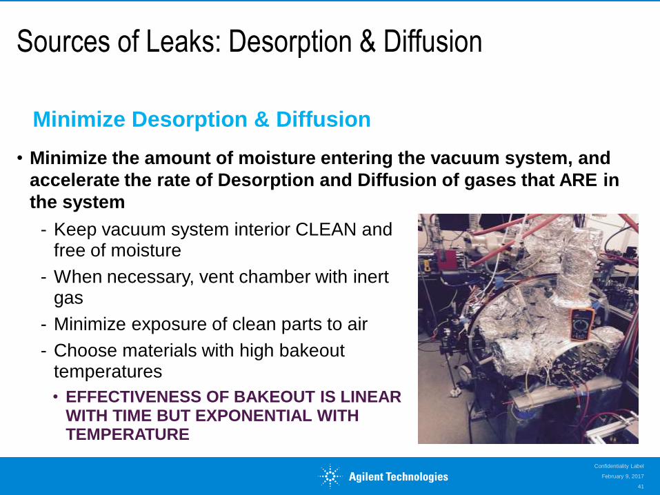
Sources of Leaks: Desorption & Diffusion
• Minimize the amount of moisture entering the vacuum system, and
accelerate the rate of Desorption and Diffusion of gases that ARE in
the system
February 9, 2017
Confidentiality Label
41
Minimize Desorption & Diffusion
- Keep vacuum system interior CLEAN and free of moisture
- When necessary, vent chamber with inert gas
- Minimize exposure of clean parts to air
- Choose materials with high bakeout temperatures
• EFFECTIVENESS OF BAKEOUT IS LINEAR WITH TIME BUT EXPONENTIAL WITH TEMPERATURE

Helium Mass Spec Leak Detection
Leak Detection is usually a very sensitive technique to determine if a REAL (Outside air leaking into Vacuum System) leak exists
Theory of Operation
• Helium Leak Detector is a Mass Spectrometer ‘tuned’ to detect only Helium
- Leak Detectors are NOT useful for detecting outgassing or diffusion leaks
• Why we use Helium?
- Highly mobile, inert, (relatively) available & inexpensive, low surface absorption (easy to pump away) present in air in low quantity (≈ 5 ppm)
System Pressure
Transducer
Ion
Source
Pre-
Amplifier
+
x x x
x x x x x
x x x x x
x x x x x
x x x x x
x x x x
+ + + Gas
Flow
Magnetic
Field
Baffles Ground Slit
Signal
Amplifier
Ion
Collector
Ion
Chamber

Summary: High Vacuum
Molecular Flow requires pumps with high conductance inlets mounted as close as possible to the vacuum system
High Vacuum Pump selection depends on the importance of:
• Oil vs Oil-free Process
• Dominant Gas Source
Ionization Vacuum Gauges are most suitable for High Vacuum; Gauges are gas type dependent
In High Vacuum, OUTGASSING (Desorption and Diffusion) is the dominant factor (vs Chamber Volume) in determining pumpdown time and base pressure
Techniques for troubleshooting HIGH VACUUM applications include Pumpdown Curves, Rate-of-Rise Tests and Helium Mass Spec Leak Detection
Techniques for achieving lower base pressure include Materials Selection, System & Component Cleaning (and surface treatment) and Bakeout
• Pump Speed vs Base Pressure
• Audible Noise & Vibration

Vacuum Education Programs
For Information on Agilent’s Vacuum Technology Products and Services, please e-mail [email protected] or call 800-882 7426, and select option 3.
To learn about more Agilent Vacuum Technology Education programs, including
• UHV Seminars at your institution
• Scheduled multi-day classes in Vacuum Practice and Leak Detection
• Custom multi-day classes at your site
• Other custom training classes to fit your needs
Please e-mail Robin Arons ([email protected]), or call Customer Care at 800-882-7426 (Option 3) for more details on these programs
February 9, 2017
Confidentiality Label
44

Next Live Webinar: High Vacuum (April 4)
Ultra-High Vacuum Webinar deals with the process of generating, measuring, and maintaining Ultra-High Vacuum Pressure (10-8 Torr to approx. 10-12 Torr).
Participants will learn about UHV Pumps (Ion Pumps, etc) and about modifications to High Vacuum Gauges to make them more suitable for UHV.
Considerations for constructing a vacuum system or troubleshooting leaks in the Ultra-High Vacuum regime will also be discussed
http://www.agilent.com/en-us/training-events/eseminars/vacuum
To Register, Visit: