specification for automated pneumatic waste collection …
TRANSCRIPT

Draft PAS 908:2018
WARNING. THIS IS A DRAFT AND MUST NOT BE REGARDED OR USED AS A PAS. THIS DRAFT IS NOT CURRENT
BEYOND 19 April 2018.
PAS 908_Draft 1_for public consultation 1
© The British Standards Institution 2017
Draft PAS 908:2018
Specification for automated pneumatic waste collection systems
IMPORTANT INFORMATION
This PAS has been edited in accordance with PAS 0:2012 and BSI house style.
Please note that this is a draft and not a typeset document. Persons commenting on this draft are advised not
to comment on matters of typography and layout.
This is a working draft and is issued to public consultation – please also
download the PDF of this PAS to better view some of the figures.
http://drafts.bsigroup.com/Home/Details/59725
Public consultation closes on 19th April 2018 and this draft is not valid beyond
that date.
No copying is allowed, in any form, without written permission from BSI except as
permitted under the Copyright, Design and Patent Act 1988 or for circulation within a
participating organization and/or its membership network for briefing purposes.
Electronic circulation is limited to dissemination by email within such an organization and
its members
Any formatting in this draft is to aid readability and does not reflect the final format of this PAS

Draft PAS 908:2018
WARNING. THIS IS A DRAFT AND MUST NOT BE REGARDED OR USED AS A PAS. THIS DRAFT IS NOT CURRENT
BEYOND 19 April 2018.
PAS 908_Draft 1_for public consultation 2
© The British Standards Institution 2017
Contents
Foreword ........................................................................................................................................................... 4
0 Introduction .................................................................................................................................................... 5
1 Scope ........................................................................................................................................................ 10
2 Normative References ............................................................................................................................... 11
3 Terms and definitions ................................................................................................................................ 12
4 Design planning ......................................................................................................................................... 17
4.1 General ..................................................................................................................................................... 21
4.2 Step 1 – Waste definition ......................................................................................................................... 21
4.3 Step 2 – Operational factors .................................................................................................................... 22
4.4 Step 3 – Waste deposit – Inlet system ..................................................................................................... 26
4.5 Step 4 – Transportation system – Pipe network ...................................................................................... 33
4.6 Step 5 – Collection system – Collection station ....................................................................................... 37
4.7 Step 6 – Optimize solution ....................................................................................................................... 60
5 Procurement/installation .......................................................................................................................... 62
5.1 General ..................................................................................................................................................... 62
5.2 Scope of works ......................................................................................................................................... 62
5.3 Prequalification – Design build suppliers of PWCS systems .................................................................... 64
5.4 Electrical control and monitoring system ................................................................................................ 68
5.5 Installation ............................................................................................................................................... 68
Annex A (normative) Waste densities ............................................................................................................... 71
Annex B (normative) Waste types accepted by a PWCS ..................................................................................... 73
Annex C (normative) DV room and chamber Sizes ............................................................................................. 74
Annex D (normative) Architectural/civil/MEP requirements ............................................................................. 75
Annex E (normative) Pipe bends ....................................................................................................................... 79

Draft PAS 908:2018
WARNING. THIS IS A DRAFT AND MUST NOT BE REGARDED OR USED AS A PAS. THIS DRAFT IS NOT CURRENT
BEYOND 19 April 2018.
PAS 908_Draft 1_for public consultation 3
© The British Standards Institution 2017
Annex F (informative) Collection station footprints ........................................................................................... 83
Annex G (informative) Sound Levels.................................................................................................................. 84
Annex H (normative) Electrical power requirements ......................................................................................... 86
Annex I (normative) Product requirements ....................................................................................................... 89
Annex J (informative) Commissioning Procedure Outline .................................................................................. 95
Annex K (informative) Operation and maintenance .......................................................................................... 98

Draft PAS 908:2018
WARNING. THIS IS A DRAFT AND MUST NOT BE REGARDED OR USED AS A PAS. THIS DRAFT IS NOT CURRENT
BEYOND 19 April 2018.
PAS 908_Draft 1_for public consultation 4
© The British Standards Institution 2017
Foreword
This Publicly Available Specification (PAS) was sponsored by Envac. Its development was facilitated by BSI
Standards Limited and it was published under license from the British Standards Institution. It came into effect on
MMDDYYYY.
Acknowledgement is given to Victoria Bond, Envac, as the technical author, and the following organizations that
were involved in the development of this PAS as members of the steering group:
[List of SG members]
The British Standards Institution retains ownership and copyright of this PAS. BSI Standards Limited as the
publisher of this PAS reserves the right to withdraw or amend this PAS on receipt of authoritative advice that it is
appropriate to do so. This PAS will be reviewed at intervals not exceeding two years, and any amendments arising
from the review will be published as an amended PAS and publicized in Update Standards.
This PAS is not to be regarded as a British Standard. It will be withdrawn upon publication of its content in, or as, a
British Standard.
The PAS process enables a specification to be rapidly developed in order to fulfil an immediate need in industry. A
PAS can be considered for further development as a British Standard, or constitute part of the UK input into the
development of a European or International Standard.
Use of this document
It has been assumed in the preparation of this PAS that the execution of its provisions will be entrusted to
appropriately qualified and experienced people, for whose use it has been produced.
Presentational conventions
The provisions of this PAS are presented in roman (i.e. upright) type. Its requirements are expressed in sentences
in which the principal auxiliary verb is “shall”.
Commentary, explanation and general informative material is presented in italic type, and does not constitute a
normative element.
Contractual and legal considerations
The publication does not purport to include all the necessary provisions of a contract. Users are responsible for its
correct application.
Compliance with a PAS cannot confer immunity from legal obligations.
Draft PAS 908:2018
WARNING. THIS IS A DRAFT AND MUST NOT BE REGARDED OR USED AS A PAS. THIS DRAFT IS NOT CURRENT
BEYOND 19 April 2018.
PAS 908_Draft 1_for public consultation 5
© The British Standards Institution 2017
0 Introduction
0.1 General
Over half of the world’s population currently lives in urban areas. This provides significant challenges to cities and
urban areas, in particular in terms of maintaining basic essential services, such as health, education, sanitation,
clean water, renewable energy for heating, cooling and electricity, transportation and minimising pollution.
World‐wide waste generation is ever increasing, with current1 global Municipal Solid Waste (MSW) generation
levels at approximately 1.3 billion tonnes per year, representing generation rates of 1.2kg per person per day.
With the inherent space and access pressures associated with high density urban development, plus that of
transport congestion and emissions, alternative solutions to conventional waste management are required to
manage the waste generated. Where new builds are designed for sustainability and energy reduction, waste
collection can be a major contributory factor in the eco‐environment due to carbon emissions from collection
vehicles, and air quality impacts from diesel particulates.
The increased implementation of technologies such as Pneumatic Waste Collection Systems (PWCS) will improve
and enhance upon conventional methods of waste collection and minimize some of the issues associated with
existing collection methods, such as access, timing, frequency of collection and excessive number of vehicle
movements.
0.2 The need for this PAS
Although standards exist for waste chutes for high‐rise developments, there is a requirement to standardize
distributed waste systems which remove waste through a pneumatic based system and sort the waste into
respective recycling containers for collection and processing. These solutions range for different functional uses,
for example:
large housing blocks;
sporting stadiums;
shopping malls;
airport handling services;
city centres;
universities; and
cultural centres
In addition to waste, variants in PWCS can also handle items such as laundry, often applied in hospitals.
1 Waste Generation, Urban Development Series – Knowledge Papers, World Bank, 2015
Draft PAS 908:2018
WARNING. THIS IS A DRAFT AND MUST NOT BE REGARDED OR USED AS A PAS. THIS DRAFT IS NOT CURRENT
BEYOND 19 April 2018.
PAS 908_Draft 1_for public consultation 6
© The British Standards Institution 2017
This PAS specifies the performance requirements and the test method for safety critical installed components. As
the systems use negative pressure, it is important that valves, seals, and interlocks are all specified to the
required quality standard.
This is a whole system specification, PWCS suppliers, base their designs not only on engineering standards and
compliance, but also on empirical data they have collated during their working history. The efficiency of the
system is dependent on the performance of individual components managed by a supplier’s unique control
system, based on research and development and lessons learnt from former PWCS they may have implemented
over the past 50 years.
0.3 The Purpose
The purpose of this PAS is to provide a performance based requirement for 400mm and 500mm diameter pipe
PWCS systems that are as economical and efficient as possible, so that if properly maintained and serviced they
will provide the expected operation during the expected design life.
By setting a benchmark standard for quality and safety of systems this PAS aims to:
1) outline the benefits of PWCS to developers and end users;
2) provide urban planners, architects and designers with a reliable reference for design and specification;
3) improve tender consistency;
4) allow suppliers to provide more cost efficient solutions based on standardized products; and
5) highlight a PWCS as a potential part of a wider integrated systems solution for cities.
It is not the intention of this PAS to limit the research and development of suppliers in order to provide innovative
solutions or to limit the use of systems to 400mm and 500mm diameter pipeline.
0.4 What is a PWCS?
This PAS presents a specification for the use of PWCSs, providing a viable alternative to conventional waste
collection systems, reducing the need for trucks and manual handling of waste and providing the flexibility to
manage increased tonnages as populations grow.
Simply put, the fundamental components of any PWCS involve the depositing of waste into a bin or inlet door,
which is then vacuumed via a pipe network to a central waste station (as per Figure 1). The PWCS is driven by a
control system which uses sensors to determine when to vacuum the waste from different inlet points, using
electricity and air.
Full vacuum systems are a variation of the PWCS defined in this PAS to the extent that they maintain a consistent
vacuum and transport waste to the collection station each and every time waste is deposited in the system. Each
waste inlet includes a storage section and a discharge valve and is similarly sized to a waste inlet in a gravity
chute.

Draft PAS 908:2018
WARNING. THIS IS A DRAFT AND MUST NOT BE REGARDED OR USED AS A PAS. THIS DRAFT IS NOT CURRENT
BEYOND 19 April 2018.
PAS 908_Draft 1_for public consultation 7
© The British Standards Institution 2017
Figure 1 – Pneumatic waste collection System: deposit – transport – collect
Outdoor Inlets Transportation Pipe Collection Station
0.5 Why implement a PWCS – drivers and benefits?
The PWCS system can be used as a whole city system or as an integrated part of the waste management network,
with the ability to move waste economically for distances of up to 3 kilometres.
Waste inlets can be placed in public areas such as streets or parks (green areas), inside buildings, stairways or
lobbies or on commercial premises for receipt of waste. The waste is held in storage sections until it is vacuumed
to a central waste station. This station may be situated outside of the city, allowing truck access to collect the
waste from a less congested traffic area, with good access and reduced (health and safety) risk to people, if
placed away from the main population.
The key benefits to implementation of a PWCS can include the following (and also as per Figure 2):
Logistics:
reduced vehicle distances travelled;
minimize collection scheduling issues (e.g. no restricted timing of access to bins);
minimize access issues (e.g. waste vehicles in busy or narrow streets);
above ground space saving.
Environmental:
reduced collection vehicle distances travelled;
ability to utilize renewable energy sources, and so reduce diesel energy requirements;
improved hygiene;
litter reduction (no bin overflow);
reduced odour issues;

Draft PAS 908:2018
WARNING. THIS IS A DRAFT AND MUST NOT BE REGARDED OR USED AS A PAS. THIS DRAFT IS NOT CURRENT
BEYOND 19 April 2018.
PAS 908_Draft 1_for public consultation 8
© The British Standards Institution 2017
reduced noise issues associated with collection vehicles;
reduced vermin.
Health and safety:
Reduced vehicles in heavy footfall area reduces risk of pedestrian injury;
Reduced manual handling, reduces risk to waste collection employees.
Flexibility:
inlet locations can be placed in public realm or indoors;
number of inlets is flexible and can be designed bespoke to any development;
smooth operations 365 days per year (e.g. minimal to no disruption regardless of what is happening above
ground, such as severe weather events, strikes, protests, sporting events etc);
security advantages – inlets in public realm can be fitted with automatic locking mechanism, which can be
initiated remotely from the control system.
Cost:
minimized operating costs;
More available leasable floor space or amenity space above ground.
A 2013 ISWA report [2] stated that: “… the use of underground (pneumatic) systems result in a more efficient
management of urban waste, enhancing both the city’s environmental conditions and the financial aspects of the
operations.”
Figure 2 – Conventional waste collection versus PWCS

Draft PAS 908:2018
WARNING. THIS IS A DRAFT AND MUST NOT BE REGARDED OR USED AS A PAS. THIS DRAFT IS NOT CURRENT
BEYOND 19 April 2018.
PAS 908_Draft 1_for public consultation 9
© The British Standards Institution 2017
0.6 Who should use a PWCS / who is this PAS relevant to?
This PAS is of interest to any developer, architect, engineer or intended purchaser / user of a PWCS.
The objective of the PAS is to provide a specification for the performance requirements and testing of distributed
pneumatic waste collection and source separation. The adoption of the PAS by users can provide an alternative to
conventional methods.
0.7 Existing users of PWCS (examples)
PWCSs have been in use since the 1960s. There are now believed to be over 1,000 PWCSs in use worldwide in
over 20 countries.
PWCSs have been incorporated into new developments across Europe, in Saudi Arabia, the United Arab Emirates,
Taiwan, South Korea and Hong Kong [3], serving residential areas, business premises, town centres, industrial
kitchens, hospitals and airports.

Draft PAS 908:2018
WARNING. THIS IS A DRAFT AND MUST NOT BE REGARDED OR USED AS A PAS. THIS DRAFT IS NOT CURRENT
BEYOND 19 April 2018.
PAS 908_Draft 1_for public consultation 10
© The British Standards Institution 2017
1 Scope
This PAS specifies requirements for stationary automated pneumatic waste collection systems.
This PAS is applicable to systems used for the automated pneumatic‐based collection of solid mixed waste and
recyclable waste, including source separation, from residential, commercial and medical environments.
This PAS includes guidance on methods for the testing, commissioning and safe operation of the system where
400 mm and 500 mm transport pipe is used as standard.
This PAS is for use by any developer, design consultant, system supplier, waste management supplier or installer
of automated pneumatic waste collection systems.
NOTE The scope of PWC systems and their application is considered too wide to cover in a single PAS document
and has therefore been limited to systems that have been used most frequently for solid mixed waste collection.
Other PWC systems exist which include larger diameter pipe networks and smaller diameter pipe networks, and
whilst this scope does not cover these systems, many of the principles can be applied. There is also a much broader
range of use for smaller diameter systems which could be incorporated into future documents.
This PAS does not cover:
a) collection of:
1) liquid waste;
NOTE wastes including for example waste water, sewage sludge, industrial effluents.
2) commercial kitchen waste;
NOTE segregated commercial kitchen waste only, excluded as there are special PWC systems to handle
this type of waste more effectively.
3) medical waste;
b) systems with transport pipe less than 400mm diameter, or more than 500mm diameter;
c) hazardous environments;
d) mobile automated pneumatic waste collection systems;
e) laundry collection systems; or
f) waste chutes.
NOTE BS 1703 gives requirements for waste chutes.

Draft PAS 908:2018
WARNING. THIS IS A DRAFT AND MUST NOT BE REGARDED OR USED AS A PAS. THIS DRAFT IS NOT CURRENT
BEYOND 19 April 2018.
PAS 908_Draft 1_for public consultation 11
© The British Standards Institution 2017
2 Normative References
The following documents, in whole or in part, are normatively referenced in this document and are indispensable
for its application. For dated references, only the edition cited applies. For undated references, the latest edition
of the referenced document (including any amendments) applies.
Standards publications
BS EN 61131‐3, Programmable controllers ‐ Part 3: Programming languages
BS 1703:2005, Refuse Chutes and Hoppers – Specification
BS 476‐4:1970, Fire tests on building materials and structures – Non‐combustibility test for materials
BS EN 805:2000, Water supply – Requirements for systems and components outside buildings
BS EN 10027‐1, Designation systems for steels – Part 1: Steel names
BS EN ISO 3183:2012, Petroleum and natural gas industries—steel pipe for pipeline transportation systems
BS EN‐60204‐1, Safety of machinery – Electrical equipment of machines – Part 1: General requirements
BS ISO 1161:2016, Series 1 freight containers ‐‐ Corner and intermediate fittings – Specifications
NFPA 82, Standard on Incinerators and Waste and Linen Handling Systems and Equipment
Other publications
CHURCHER, D., SANDS J,. BG6/2014, A Design Framework for Building Services. 4th edition. Bracknell: The Building
Services Research and Information Association (BSRIA), 2014.
AMERICAN PETROLEUM INSTITUTION. API 5L, Specification for Line Pipe. American Petroleum Institution, 2004.
AMERICAN SOCIETY OF MECHANICAL ENGINEERS. ASME B31.9‐2014, Building Services Piping – ASME Code for
Pressure Piping, B31. The American Society of Mechanical Engineers, 2014.
AMERICAN SOCIETY OF MECHANICAL ENGINEERS. Boiler and Pressure Vessel Code (BPVC)

Draft PAS 908:2018
WARNING. THIS IS A DRAFT AND MUST NOT BE REGARDED OR USED AS A PAS. THIS DRAFT IS NOT CURRENT
BEYOND 19 April 2018.
PAS 908_Draft 1_for public consultation 12
© The British Standards Institution 2017
3 Terms and definitions
For the purposes of this PAS, the following terms and definitions apply.
3.1 air inlet
3.1.1 primary air inlet
entry point of air into the PWC system that is used to convey the waste to the collection station
3.1.2 secondary air inlet
additional air inlet, often adjacent to DVs, used to maintain required pressure throughout the transport pipe
3.2 air intake
air coming into the pipe network
3.3 collection station
receiving station for waste delivered through the pipe network
3.4 compactor
machine, consisting of a compacting unit and container that compacts loose materials into a container
NOTE Loose materials can include, but are not limited to paper, plastics, textiles, cans, cardboard and mixed
waste.
NOTE The compactor in a PWCS system is usually connected directly between the cyclone and the container
maintaining the full vacuum seal
3.5 compressor
machine that compresses air or other gases
3.6 container
sealed container under negative pressure located in the collection station for temporary storage of waste, prior to
haulage to a municipal waste station or treatment facility
3.7 container separation
device for separating mixed size particles from a gas stream
3.8 control system
network of electric and electronic units for remote computer controlled operation of the PWCS.

Draft PAS 908:2018
WARNING. THIS IS A DRAFT AND MUST NOT BE REGARDED OR USED AS A PAS. THIS DRAFT IS NOT CURRENT
BEYOND 19 April 2018.
PAS 908_Draft 1_for public consultation 13
© The British Standards Institution 2017
NOTE Control cabinets, control boxes, software, cables and junction boxes are regarded as parts of the control
system.
3.9 cut‐off valve
valve used for air stream control in the collection station which has two positions only, open or closed
3.10 cyclone
device for separating mixed size particles from a gas stream by the use of a vortex [SOURCE: BS ISO 3857‐4:2012,
2.23]
NOTE Gas laden with particles enters the cyclone and is directed to flow in a spiral causing the particles to fall out
and collect at the bottom. The gas exits near the top of the cyclone.
3.11 discharge valve (DV)
valve that prevents waste from entering the pipe net from the storage section
NOTE The DV is normally closed. Disposed waste is temporarily stored on or behind the DV. The DV is opened when
the waste is collected.
3.12 erosive material
material which might cause rapid erosion of the pipe
NOTE For example, glass or metal.
3.13 exhauster
vacuum pump or fan, used as single or multiple setup, in series or parallel, to create negative pressure and air
flow in the transport pipe
3.14 fan
device with rotating blades that creates a current for air cooling or ventilation
NOTE A radial fan is often used as exhauster machine in a PWCS. An axial fan is often used in ventilation systems.
3.15 filter
porous device through which gases (or liquids) pass through in order to remove impurities
NOTE Aaset of dust and deodorizing filters are housed in a prefabricated or site constructed filter chamber located
in the collection station after the exhausters and then vented to atmosphere.
3.16 fraction
proportion of the total waste separated at source prior to depositing into the inlet

Draft PAS 908:2018
WARNING. THIS IS A DRAFT AND MUST NOT BE REGARDED OR USED AS A PAS. THIS DRAFT IS NOT CURRENT
BEYOND 19 April 2018.
PAS 908_Draft 1_for public consultation 14
© The British Standards Institution 2017
NOTE Typical fractions include mixed dry recyclables, residual waste, organic waste.
3.17 full vacuum
constant vacuum
NOTE In this PAS, full vacuum refers to a type of PWCS where a constant vacuum is maintained for all inlets and
the storage section at each inlet is limited in size similar to a waste inlet.
3.18 gravity chute
ventilated, essentially vertical pipe, used for transferring waste/recycling or linen by gravity to a lower floor
[SOURCE: BS 1703:2005, 3.1, modified]
3.19 inlet station
outdoor or indoor disposal station, comprised of inlets, where waste and recycling items are placed into the
system
3.20 mixed dry recyclables
paper, cardboard, plastics, cans, glass, polystyrene
3.21 organic waste
food and garden waste
3.22 peak load
maximum waste load carried by the PWCS
3.23 pipe network
interlinked, connected pipes from waste inlets to collection station
3.24 residual waste
non‐recyclable waste materials remaining after recyclables have been extracted
3.25 rotating screen
revolving device, located in the cyclone, which separates coarse particles from transport air
NOTE Part of the standard separator (3.28). Prevents coarse particles from the waste from reaching the
exhausters.

Draft PAS 908:2018
WARNING. THIS IS A DRAFT AND MUST NOT BE REGARDED OR USED AS A PAS. THIS DRAFT IS NOT CURRENT
BEYOND 19 April 2018.
PAS 908_Draft 1_for public consultation 15
© The British Standards Institution 2017
3.26 screw tank
waste container used for intermediate storage underneath one or several inlets, connected to the transport pipe
network by a slide valve with a rotating screw used to empty the tank
3.27 sectioning valve
valve which divides pipe network into different sections to increase collection efficiency
3.28 separator
device, located in the collection station, which separates the transported waste from the air flow
NOTE Typically this is a cyclone.
3.29 silencer
device which reduces noise in the exhaust air pipe
3.30 solid mixed waste
mixed waste consisting of recyclable and non‐recyclable content
3.31 storage in bend
shortened storage section below last inlet, with a 90 degree bend connection to a slide valve on the transport
pipe
3.32 storage section
section of pipe between the DV and the gravity chute for temporary storage of waste
NOTE The storage station typically includes an inspection opening and air intake.
3.33 transport pipe
cylindrical pipes, constituting a network (3.18) for transport of air and material
3.34 vacuum (partial)
negative pressure in the system created by running the exhausters or vacuum pumps
3.35 vacuum pump
pump used to create negative pressure in the transport pipe
3.36 venturi pipe
pipe with a constriction that increases the velocity and lowers the pressure of the air passing through it

Draft PAS 908:2018
WARNING. THIS IS A DRAFT AND MUST NOT BE REGARDED OR USED AS A PAS. THIS DRAFT IS NOT CURRENT
BEYOND 19 April 2018.
PAS 908_Draft 1_for public consultation 16
© The British Standards Institution 2017
NOTE Venturi pipes are used for measuring air speed and located between the waste separator and the
exhausters.
3.37 vertical slide valve
valve used for air stream control with two positions only, open or closed
3.38 waste inlet
opening for depositing waste into the system
NOTE A waste inlet can be:
a) indoor inlet on a single floor;
b) outdoor inlets;
c) attached to a screw tank; or
d) attached to a gravity chute in compliance with BS 1703.

Draft PAS 908:2018
WARNING. THIS IS A DRAFT AND MUST NOT BE REGARDED OR USED AS A PAS. THIS DRAFT IS NOT CURRENT
BEYOND 19 April 2018.
PAS 908_Draft 1_for public consultation 17
© The British Standards Institution 2017
4 Design planning
COMMENTARY ON CLAUSE 4.
Like any other infrastructure‐led service, such as sewage, water and electricity, pneumatic waste collection can be
used as part of any modern day waste management system and be a natural element in an integrated systems
perspective on cities and city districts. The system can be used for a variety of functional areas, including
residential and commercial developments, hospitals, airports and town centres including parks and pedestrian
areas.
The pneumatic waste collection system (PWCS) follows the following principles (see Figure 3).
a) Deposit – Users deposit waste into waste inlets, which can either be indoors or outdoors. The
waste/recycling bags are stored temporarily inside the waste inlet above a closed discharge valve (DV). All
full waste inlets are then emptied at regular intervals. Automatic emptying is governed by a control
system in the collection station, which is typically located on the outskirts of the development it serves and
linked to the inlets via a network of underground pipes.
b) Transport – When the control system senses that it is time to empty the waste inlets, the PWCS
exhauster/vacuum pump system is initiated and a vacuum is created in the pipe network. A supply air
valve is opened in order to allow air into the pipe network to transport waste from the waste inlets to the
waste collection station. The DVs beneath the waste inlets are then opened one by one. The
waste/recycling bags fall down into the pipe network and are sucked away to the waste collection station
at speeds of up to 70 kph and over distances as long as 3 km from the waste inlets.
c) Collect – Waste at the collection station is sucked through a cyclone or separator, where it is separated
from the transport air. It then falls down into a compactor where it is compacted and fed into a sealed
container. The transport air is released via a flue after having passed through a series of cleaning filters
and silencers.
d) Treat – The system can be designed to feed into a range of downstream technologies. These are outside
the scope of this PAS.

Draft PAS 908:2018
WARNING. THIS IS A DRAFT AND MUST NOT BE REGARDED OR USED AS A PAS. THIS DRAFT IS NOT CURRENT
BEYOND 19 April 2018.
PAS 908_Draft 1_for public consultation 18
© The British Standards Institution 2017
Figure 3 – How a PWCS works
Deposit – Indoor Inlet: accessible inlet doors for residents / tenants to deposit waste. Usually connected to gravity chutes to serve upper
floors of buildings.
Deposit – Outdoor Inlet: accessible inlets in the form of bins for residents / tenants / members of the public to deposit waste. Used in public
realm and less densely populated areas where indoor gravity chutes are not normally used.
Transportation – Pipe Network: In most urban environments, pipe diameter ranges between 400 and 500mm. The pipe routing of the pipe is
flexible and pipes are suspended or buried.
Collect ‐ Collection Station: The waste destination. Main equipment and storage containers are housed here, where waste will be housed until
collected and taken for off‐site treatment. The location can be flexible and the station can be above or below ground.
In order to design a PWCS, there are the following six key steps of the design planning process to follow (see Figure
4).
General requirements:
Step 1 – Waste definition (see 4.2);
Step 2 – Operational factors (see 4.3).
Performance requirements:
Step 3 – Waste deposit – Inlet system (see 4.4);
Step 4 – Transportation system – Pipe network (see 4.5);
Step 5 – Collection station (see 4.6);
Step 6 – Optimize the solution (see 4.7).

Draft PAS 908:2018
WARNING. THIS IS A DRAFT AND MUST NOT BE REGARDED OR USED AS A PAS. THIS DRAFT IS NOT CURRENT
BEYOND 19 April 2018.
PAS 908_Draft 1_for public consultation 19
© The British Standards Institution 2017
Figure 4 – PWCS design planning process

Draft PAS 908:2018
WARNING. THIS IS A DRAFT AND MUST NOT BE REGARDED OR USED AS A PAS. THIS DRAFT IS NOT CURRENT
BEYOND 19 April 2018.
PAS 908_Draft 1_for public consultation 20
© The British Standards Institution 2017

Draft PAS 908:2018
WARNING. THIS IS A DRAFT AND MUST NOT BE REGARDED OR USED AS A PAS. THIS DRAFT IS NOT CURRENT
BEYOND 19 April 2018.
PAS 908_Draft 1_for public consultation 21
© The British Standards Institution 2017
4.1 General
The system shall transport waste and recyclable fractions from a waste inlet to a collection station.
NOTE The design of the system for each specific development, should be informed as a minimum by the defined
waste types and volumes to be handled and the operational timings and associated system capacity requirements.
These can be identified as described in step 1 and step 2.
4.2 Step 1 – Waste definition
NOTE The most important step in the design planning process is the definition of waste types and volumes to be
transported through the system. Waste fractions behave differently when being transported by negative air
pressure, consequently affecting the amount of energy needed to transport them.
4.2.1 General
In order to establish baseline waste data for the system, the following shall be identified and recorded:
a) waste types and densities, including:
1) waste fractions (i.e. mixed dry recyclables, organic waste, residual waste) (see 4.2.2.1);
2) average density (see 4.2.2.2);
3) erosive materials (see 4.2.2.3);
b) waste volume (see 4.2.3).
4.2.2 Waste types and densities
4.2.2.1 Waste fractions
The number of waste fractions to be sorted and collected separately or as a whole (mixed) shall be identified in
consultation with the customer to input in to the system design.
NOTE Attention is drawn to applicable local regulations. Typical waste fractions can be found in Annex B.
4.2.2.2 Average density
The average density (kg/m3) of the waste in each identified fraction shall be calculated to input in to the system
design.
NOTE Examples of waste densities are given in Annex A.
4.2.2.3 Erosive materials
Any types of erosive materials that might be transported through the system shall be identified.
NOTE 1 Examples of erosive materials include glass and metal.

Draft PAS 908:2018
WARNING. THIS IS A DRAFT AND MUST NOT BE REGARDED OR USED AS A PAS. THIS DRAFT IS NOT CURRENT
BEYOND 19 April 2018.
PAS 908_Draft 1_for public consultation 22
© The British Standards Institution 2017
NOTE 2 Erosive materials should not exceed 10% of the total weight of the waste collected.
NOTE 3 In order to determine accurate waste densities, a waste composition analysis may be conducted.
NOTE 4 Good practice methodologies for conducting waste composition analyses can be found in Solid Waste
Technology and Management publications [4], with detailed waste sampling to be conducted in accordance with
BS EN 14899:2005, to be read in conjunction with BS EN 13965‐1.
Suppliers of PWCS systems might have experience in providing waste composition analysis specific to their
systems.
Waste types accepted in a PWCS shall be in accordance with Annex B.
4.2.3 Waste volume
The estimated volume of each waste fraction shall be calculated, dependent on building type, function (e.g.
commercial, residential) and locality/demographic.
NOTE Methods of calculation and examples can be found in BS 5906 and Annex A. Local/regional authority
guidelines should also be consulted.
4.2.4 Gravity chute size
The design of gravity chutes shall conform to either BS 1703:2005, Clause 6, or NFPA 82, 6.3.2.
NOTE In order to reduce risk of chute blockages, for 500mm diameter PWCS the maximum chute diameter should
be 500 mm. For 400 mm diameter PWCS the maximum chute diameter should be 400 mm. Alternatively, inlet
door sizes can be reduced to assist in minimizing risk. Where local requirements dictate a larger chute diameter
than the PWCS diameter, a cone reduction may be necessary.
4.2.5 Inlet door
The waste inlet door size shall be dependent on the intended waste fractions and their origin (e.g. residential,
commercial) and waste inlet location (e.g. outdoor inlet or single storey indoor inlet).
The design of inlet doors installed in gravity chutes shall conform to either BS 1703:2005, Clause 6 and NFPA 82,
6.3.2.
NOTE Other inlets are subject to local building codes.
4.3 Step 2 – Operational factors
4.3.1 General
The following design inputs shall be identified in order to determine system capacity:
a) average performance values – system availability/in‐use period (see 4.3.2);
b) storage capacity – the amount of waste the gravity chutes can temporarily store (see 4.3.3);

Draft PAS 908:2018
WARNING. THIS IS A DRAFT AND MUST NOT BE REGARDED OR USED AS A PAS. THIS DRAFT IS NOT CURRENT
BEYOND 19 April 2018.
PAS 908_Draft 1_for public consultation 23
© The British Standards Institution 2017
c) collection times – the time it takes to collect waste from each sub‐system, including number of discharge
valve openings (see 4.3.4);
d) disposal patterns/peak periods – the pattern of disposal for each of the waste fractions, consisting of
average load and peak load times (see 4.3.5).
The collection time shall be less than the time it takes the system to fill up to storage capacity.
NOTE 1 When considering availability of the system, it is important to note that in any 24‐hour period, waste can
be deposited until the capacity of the storage chute is filled. Actual operational time can be limited, due to the
allowance for maintenance, unattended (off) time and idling (see 4.3.2).
NOTE 2 There are inlet station types for indoor and outdoor installation. The choice of inlet station does not
normally affect the configuration of the installation in any other way than the placement of the gravity chutes and
DVs. The choice of inlet station can therefore be based on other criteria such as practicality, aesthetic appearance,
etc.
NOTE 3 Weighing of waste can be incorporated into PWC systems. This can be done on an individual basis (e.g.
radio frequency identification (RFID) can be used to identify the household depositing the waste bag). Colour
sensors can be used for different waste and recyclable streams, and weight sensors within the inlet register the
weight of each bag. Weighing can also be achieved on a per property basis (e.g. the compactor/container can be
weighed when removed, or the weight of waste/recyclables collected can be recorded in the collection vehicle [if
fitted with the appropriate weighing equipment]).
RFID tagging can also be used to monitor and control user access, based on valid user cards to unlock specific
inlets within a development. User cards can be issued with different user profiles and the system can record usage
patterns. Inlets are locked by default and therefore access can be managed at certain times from the central
control system (e.g. .during large public events or when the security level is raised).

Draft PAS 908:2018
WARNING. THIS IS A DRAFT AND MUST NOT BE REGARDED OR USED AS A PAS. THIS DRAFT IS NOT CURRENT
BEYOND 19 April 2018.
PAS 908_Draft 1_for public consultation 24
© The British Standards Institution 2017
4.3.2 Average performance Values
The average performance values for PWC system shall be calculated as per Table 1.
Table 1 Average performance values calculations
Parameters Value Definition
Time in operation [h/day] The time in operation is defined as the time the system is
working in collection mode (each system)
Time in standby [h/day] The time in standby is defined as the time the system is ready
to start a collection cycle
Down time [h/day] The down time is defined as the time the system is stopped
due to an alarm or maintenance.
Time in service [h/day] The time in service is defined as the time the installation is
activated (time in stand‐by plus time in operation).
Availability* [%]
The system availability is defined as the time in operation
plus the time in standby minus down time, in relation to the
time in service.
*Average Performance Values‐ Calculated according to standard FEM. 9.221/9.222.
4.3.3 Number of valves and gravity chutes
The number of valves and gravity chutes shall be calculated from:
a) waste volume (see 4.2.3);
b) storage capacity of the gravity chute.
Each gravity chute shall have at least one DV. Where a chute diverter is used to collect two fractions there shall be
2 DV’s per chute.
4.3.4 Storage capacity per gravity chute
The storage capacity per gravity chute shall be calculated using the formula:
Storage capacity (m3) = available storage volume ( m3) x Filling rate %
NOTE 1 The filling rate depends on the waste fraction, but for mixed fraction a rule of thumb is between 50%–75%.
of the storage section volume based on the maximum storage height It defines the level at which the storage
section is signaled as full and is a balance of frequency of collection and the actual height of the storage section
See Annex A (column: maximum storage height in gravity chute).

Draft PAS 908:2018
WARNING. THIS IS A DRAFT AND MUST NOT BE REGARDED OR USED AS A PAS. THIS DRAFT IS NOT CURRENT
BEYOND 19 April 2018.
PAS 908_Draft 1_for public consultation 25
© The British Standards Institution 2017
NOTE 2 Example: for a preliminary chute size of 500 mm, with waste stored up to a height of 2.5 m, there is an
available storage volume of 375 l (or 0.375 m3) for the specified type of waste.
4.3.5 Storage section – gravity chute to PWCS transition:
The storage section shall be placed between the lowest section of the gravity chute and the DV.
NOTE An inspection opening should be installed in the lower part of the storage pipe to make it possible to cleanse
the pipe.
The lower part of the storage section should be mounted with a flange so that it is easy to remove. This allows
easy access for maintenance and rinsing.
4.3.6 Collection times
The number of DV openings required per day for the system shall be calculated using the formula:
Total waste volume per day (m3) = Number of DV openings required per day
Average storage capacity per gravity chute ( m3)
NOTE The maximum recommended average number of DV openings per minute is two for all systems. Dividing the
total number of DV openings per day by two will therefore provide a collection time per fraction.
It’s difficult to define an exact number of DV openings per minute, as there are a number of factors affecting this,
including:
a) number of waste fractions;
b) number of sectioning valves (SV);
c) number of air valves;
d) type of valves (discharge valves, sectioning valves, etc.);
e) collection routine;
f) pipe network geometry;
g) suction distance; and
h) collection speed.

Draft PAS 908:2018
WARNING. THIS IS A DRAFT AND MUST NOT BE REGARDED OR USED AS A PAS. THIS DRAFT IS NOT CURRENT
BEYOND 19 April 2018.
PAS 908_Draft 1_for public consultation 26
© The British Standards Institution 2017
4.3.7 Disposal patterns
The disposal patterns of waste being inserted into the system in any 24‐hour period shall be established and
recorded.
NOTE This information can be identified by researching the routine behaviour of different waste producers. The
following trends could be assumed based on general working hours for Northern Europe.
a) Residential: In Northern Europe there are two main disposal patterns per day, in the morning between
07:00 and 09:00 and evening between 17:00 and 20:00.
b) Commercial: Within shops, offices and other commercial premises, it is expected that 90% of waste will be
deposited into the system after normal hours of business (typically 17:00 to 19:00 depending on the
region).
When planning and designing a PWCS, it is possible to discuss with the client/facilities management
company to determine the proposed cleaning hours.
c) Other factors affecting disposal patterns: these include maintenance down time, traffic/access
restrictions, seasonal variations, etc.
The average load placed in a system can be calculated with some allowable degree of flexibility. However, when
calculating peak loads, accuracy of calculation is vital, in order to avoid unnecessary service interruptions.
4.4 Step 3 – Waste deposit – Inlet system
4.4.1 General
Each waste inlet or gravity chute shall be fitted with at least one DV and each DV shall operate with an AV that is
close enough to allow sufficient air transport speed to be generated at the DV in order to facilitate automated
operation.
NOTE 1 An AV can operate with a group of DV‘s depending on the geometry of the network.
NOTE 2 Typical DV inlets are illustrated in 7 to Figure 9.
NOTE 3 When steps 1 and 2 have been completed and the required data defined, the system design can take
place.
Requirements for steps 3 to 6, are set out at 4.4 – 4.7.
NOTE 4 Inlet systems (sometimes known as feeding systems), require the definition and placement of inlet doors
and chutes within a development to enable all tenants and residents to deposit their waste.
This PAS has been written on the basis of requiring a gravity chute to transport waste from point of deposit to the
PWCS pipe network at basement level.
However, this is not the case (i.e. chutes are not required) if the system is servicing ground level developments,
such as low‐rise residential (townhouses/villas), ground floor retail/hospitality or other functions including public

Draft PAS 908:2018
WARNING. THIS IS A DRAFT AND MUST NOT BE REGARDED OR USED AS A PAS. THIS DRAFT IS NOT CURRENT
BEYOND 19 April 2018.
PAS 908_Draft 1_for public consultation 27
© The British Standards Institution 2017
realm bins in parks, at beach fronts, etc. In the absence of gravity chutes, the waste, once deposited, will fall
directly into the PWCS (see Figure 5), where it will be held until transportation via vacuum through the pipe
network to the collection station.
Figure 5 – Outdoor waste inlet at ground level
The physical placement of the inlet doors will determine which type of inlet system meets the placement
requirements. It is then possible to calculate how many gravity chutes are needed.
The type of inlet point(s) provided in each building are dependent on the functional uses occupying the
development. For example, in a mixed use development, there may be indoor inlets for residential and
commercial/retail, and outdoor inlets for public spaces, such as parks.
The inlet aperture and door should facilitate users in depositing waste, and be appropriate to the expected waste
streams.
The storage capacity of each inlet point should be designed to accommodate the projected waste generation rate
and the expected peak load based on the function(s) of the development. The waste and recycling deposit times
vary by tenant type/function, and are not expected to be distributed evenly throughout the day, so the storage
capacity of inlet points for all functions should reflect this.
Design requirements for inlet doors and chutes are given at 4.4.2.

Draft PAS 908:2018
WARNING. THIS IS A DRAFT AND MUST NOT BE REGARDED OR USED AS A PAS. THIS DRAFT IS NOT CURRENT
BEYOND 19 April 2018.
PAS 908_Draft 1_for public consultation 28
© The British Standards Institution 2017
Figure 6 – Typical indoor DV room

Draft PAS 908:2018
WARNING. THIS IS A DRAFT AND MUST NOT BE REGARDED OR USED AS A PAS. THIS DRAFT IS NOT CURRENT
BEYOND 19 April 2018.
PAS 908_Draft 1_for public consultation 29
© The British Standards Institution 2017
Figure 7 – Typical indoor DV room

Draft PAS 908:2018
WARNING. THIS IS A DRAFT AND MUST NOT BE REGARDED OR USED AS A PAS. THIS DRAFT IS NOT CURRENT
BEYOND 19 April 2018.
PAS 908_Draft 1_for public consultation 30
© The British Standards Institution 2017
Figure 8 – Typical outdoor DV room
4.4.2 Inlet doors and chutes
COMMENTARY ON 4.4.2
Whilst the scope of this PAS does not cover the design of gravity chutes, the number of DVs connected to a
building is dependent on the suitable placement of gravity chutes by the designer.
The physical placement and distribution of the gravity chutes and inlet doors usually requires extensive
coordination with other systems and services to meet development priorities and customer needs. Maximizing
synergies, from a whole development and integrated system perspective, can reduce the potentially competing
demands from other stakeholders with space requirements, such as building services, car parking, etc.
The competing demands and requirements of the system should be quantified based on:
embedded placement (part of the building structure);
outdoor placement;
number of inlet doors per chute;
number of inlet chutes – based on no of fractions, distance and accessibility; and
capacity – whether the planned number of users is greater than the capacity of the system.
This process should be conducted in collaboration and negotiation with the customer and will inevitably be
influenced by other conflicting requirements.

Draft PAS 908:2018
WARNING. THIS IS A DRAFT AND MUST NOT BE REGARDED OR USED AS A PAS. THIS DRAFT IS NOT CURRENT
BEYOND 19 April 2018.
PAS 908_Draft 1_for public consultation 31
© The British Standards Institution 2017
Waste and recycling inlets shall conform to Building Regulations Approved Document H Drainage and Waste
Disposal, part H6, Section 1.8, page 54 i.e. inlets shall be sited so that the distance residents are required to carry
their waste/recycling does not exceed 30m.
Gravity chute configuration and gravity chute inlet doors shall conform to BS 1703:2005 or NFPA 82. The
materials shall be non‐combustible when tested according to the requirements of BS 476‐4.
Inlet doors shall withstand a negative pressure of 2 kPa.
Inlet door dimensions shall be large enough to fit the type of waste and bags handled by the inlet.
Gravity chute/waste inlet rooms shall have cleanable surfaces in order to maintain hygiene.
Gravity chute rooms shall maintain a positive pressure in relation to the chute and a negative pressure in relation
to the external access corridor/room in order to minimize odour filtration from the gravity chute.
4.4.3 Storage section
The storage section height shall be dimensioned for the estimated volume of waste handled (see 4.2.3), and at a
maximum height as identified in Annex A.
NOTE 1 The waste levels should be automatically measured to trigger an emptying.
NOTE 2 The storage section should normally not have any cone or other reduction of the cross section below
maximum level of storage. Taking into account 4.2.4, where local requirements dictate a larger chute diameter
than the PWCS diameter, a cone reduction may be necessary.
The storage section shall be constructed of mild steel. The thickness of the storage section shall be:
a) a minimum of 2 mm in buildings up to two storeys;
b) a minimum of 3 mm in buildings above two storeys; and
c) a maximum of 8 mm (e.g. in high rise buildings with a load of ≥ 500 kg/day).
4.4.4 Discharge valve (DV)
Where used, DVs shall be placed in a DV room.
NOTE The waste is stored in a DV room until it is ready for transportation via the pipe network.
There shall be one DV per waste fraction.
The diameter of the DV shall be the same as that of the transport pipe.
NOTE If there is not sufficient vertical space between the chute and the transport pipe level for a storage section
and DV then a storage in bend solution may be used in low rise buildings.

Draft PAS 908:2018
WARNING. THIS IS A DRAFT AND MUST NOT BE REGARDED OR USED AS A PAS. THIS DRAFT IS NOT CURRENT
BEYOND 19 April 2018.
PAS 908_Draft 1_for public consultation 32
© The British Standards Institution 2017
Storage in bend, if used, shall consist of a 90 degree bend connection to the chute with a slide valve installed with
at least 2 diameters' length of straight pipe connection to the transport pipe, in order to enable the bend to hold
and store additional waste in the pipe, until such a time that it is transferred to the collection station.
DV room and chamber size shall conform to the dimensions in Annex C.
Civil/architectural design shall conform to Annex D.
Pipe bend design shall conform to Annex E.
If chute flushing is required, the storage section shall include a drain outlet.
4.4.5 Air valve (AV)
An air valve (AV) shall be placed at the end of each transport pipe inlet, adjoining the pipe network where there is
a DV or line of DVs on the branch to introduce air into the system when the required negative pressure has been
achieved.
The periodic opening of the AV shall create an air stream up to 24 m/s which is used to transport the waste, after
the DV has been opened, to the collection station.
The AV shall be located in either a DV room with suitable air supply or in an unoccupied space such as a car park
or basement plant room with sufficient air volume for the AV to operate.
NOTE 1 Where possible, air should be drawn from non‐air conditioned/heated spaces to reduce HVAC energy use
in the building(s).
NOTE 2 Typically, each AV is opened separately for 20–30 s at a time for each emptying of each DV and requires
approximately 5 m3/s air volume.
NOTE 3 Additional make‐up air might be required inside buildings and in locations where air might be lost (e.g. via
ventilation).
4.4.6 Air inlet
There shall be a secondary air inlet above the DV
NOTE 1 The air inlet provides the storage section and DV with the secondary air required to ensure reliable and
fast emptying of the chute.
The air inlet is designed to be mounted on top of a DV and is normally connected to the storage section with a
rubber sleeve and clamps. The purpose of the air inlet is to separate the waste column by introducing air between
the waste bags.
NOTE 2 Additional make‐up air might be required inside buildings and in locations where air might be lost (e.g. via
ventilation).
The air inlet shall be designed to avoid waste from entering the air inlet from the storage section and a visual test
shall be undertaken to check this.

Draft PAS 908:2018
WARNING. THIS IS A DRAFT AND MUST NOT BE REGARDED OR USED AS A PAS. THIS DRAFT IS NOT CURRENT
BEYOND 19 April 2018.
PAS 908_Draft 1_for public consultation 33
© The British Standards Institution 2017
The air inlet shall be designed to ensure that the negative pressure in the chute does not exceed ‐5Kpa during
operation of the DV .
NOTE 3 Specific requirement is dependent on air speed, pipe dimension, waste amount and waste type (including
fractions).
NOTE 4 Pressures should be tested during commissioning of the system.
.
4.4.7 Inspection opening
If the storage pipe is slanted, the inspection opening shall be in position on the upper side of the pipe.
The inspection opening shall be placed such that contact with waste in the pipe is minimized by ensuring there
are no protruding edges inside the pipe.
NOTE An inspection opening should be installed as close as possible to the DV. Exemptions can be made if there is
not enough space.
4.5 Step 4 – Transportation system – Pipe network
4.5.1 General
The pipe network shall connect and transport the waste from the storage section to the collection station.
NOTE The design of the pipe network should be conducted in consultation with relevant stakeholders, including, at
a minimum:
a) the main client;
b) planners;
c) utilities and services designers/contractors;
d) infrastructure, civils and structural contractors;
e) general contractor;
f) executive architect; and
g) design architects.
Before designing the pipe network, the following information shall be determined:
a) location and number of DVs and AVs;
b) estimated type and volume of waste per fraction; and
c) location of the collection station.

Draft PAS 908:2018
WARNING. THIS IS A DRAFT AND MUST NOT BE REGARDED OR USED AS A PAS. THIS DRAFT IS NOT CURRENT
BEYOND 19 April 2018.
PAS 908_Draft 1_for public consultation 34
© The British Standards Institution 2017
NOTE The limiting factors for the size of the system are the most important factors and should be considered when
dimensioning the system in order to achieve the following objectives:
a) to design the most efficient pipe net possible;
b) to minimize the cost of production and installation;
c) to accomplish a system which has as low energy consumption as possible;
d) to ensure the collection performance and expected lifetime; and
e) to achieve the shortest pipe length available under the project design constraints, as pipe length can be
50% of the total installation cost.
Different types of waste require different air speeds and pressures to move them, so the transport length that has
maximum pressure drop should be calculated for each waste fraction.
4.5.2 Sectioning valve (SV)
SVs shall be included in the network:
a) where the number of required DVs exceeds the limits;
b) where one part of the system is more sensitive to operational irregularities than others; and
c) to reduce the number of DVs per section increasing maximum suction distance.
NOTE Sectioning valves (SV) may be used to increase total system capacity where systems are large. Reducing
number of valves and operational pipe length by using SVs gives several advantages:
a) reduced exhauster load ;
b) longer suction distances;
c) reduced energy consumption;
d) reduced effect of DV failures; and
or as part of value engineering allowing reduction in the required exhauster capacity and number of exhausters.
4.5.3 Transport pipes
The transport pipe material shall be:
a) in conformance with BS EN ISO 3183:2012 and / or API 5L grade B where mild steel has been
used;
b) seamless, or ERW or Spiral welded pipe;

Draft PAS 908:2018
WARNING. THIS IS A DRAFT AND MUST NOT BE REGARDED OR USED AS A PAS. THIS DRAFT IS NOT CURRENT
BEYOND 19 April 2018.
PAS 908_Draft 1_for public consultation 35
© The British Standards Institution 2017
c) 6m or 12m lengths to reduce number of welded joints and joint wear.
d) of a material thickness consistent with the expected erosion during proper use over the expected
design life.
NOTE 1 The transport pipe material may be of an alternative material subject to meeting performance
requirements of erosion, negative pressure and building code constructability and durability and where supplier
can demonstrate performance. Any alternative pipe material should be designed to wear at a rate that does not
prematurely degrade or fail through the abrasive action of the erosive materials content (see 4.2.2.3) of the total
mixed and dry recyclable stream.
NOTE 2 Diameter, and pipe thickness should be selected to ensure efficient and reliable operation under the
expected loads and ambient conditions for the full design life of the PWCS.
The transport pipe shall have a diameter of DN 400 mm or DN 500 mm.
The same transport pipe diameter shall be used in all parts of the pipe network, unless a specifically engineered
solution is provided by the system designer.
NOTE 3 Dependent on system configuration, it is possible to design systems with pipe branches with a lower
diameter based on addition of compensating air valves.
The transport pipe thickness shall not be less than 6 mm on straight sections of the pipe network and not less
than 9 mm on any bends in steel pipes.
Bends shall be mild steel S235JR or S355J1 in accordance with BS EN 10027‐1 unless the erosion calculation
requires hardened steel bends.
Horizontal bends shall be long radius in the transport pipe network (See Annex E).
Vertical Bends shall be as per Annex E.
NOTE 4 bends should be sufficient to avoid causing unnecessary reductions in system efficiency and short enough
to maximize space efficiency and avoid unnecessary impact on the design development. See Annex E for typical
bend configurations.
NOTE 5 Inspection openings should be provided with sufficient regularity and in appropriate locations to ensure
that pipe maintenance and repairs are facilitated within agreed service levels.
NOTE 6 In the direction of waste transport vertically rising or falling pipes should be inclined at an angle
sufficiently small to avoid unnecessary reductions in system efficiency (typically 20 degrees in elevation and 40
degrees in declination) and sufficiently large to maximize space efficiency and avoid unnecessary impact on the
design development. See Annex E.
Efficiently designed systems will have as much horizontal pipe with the lowest number of bends as possible –
increased changes in height increases cost of installation, wear and tear and reduces maximum suction distance.
It is possible to design systems with changes in elevation that are outside the parameters above for specific

Draft PAS 908:2018
WARNING. THIS IS A DRAFT AND MUST NOT BE REGARDED OR USED AS A PAS. THIS DRAFT IS NOT CURRENT
BEYOND 19 April 2018.
PAS 908_Draft 1_for public consultation 36
© The British Standards Institution 2017
solutions, however the effect on erosion, exhauster power and performance should be specifically designed by the
PWCS designer based on experience and overall system requirements.
Erosion in transport pipes shall be calculated based on expected design loads, air speed, design life and waste
fractions density to determine minimum pipe thickness.
NOTE 7 The transport pipes are exposed to internal erosion caused by the waste. Due to the heterogeneous
composition of waste, erosion factors tend to be determined empirically. Consider that erosion is significantly
increased in bends, deviations and Y‐pipes than in straight pipes.
NOTE 8 The transport pipes shall typically achieve an air speed of 18 m/s to 24 m/s in order to efficiently
transport waste actual speed within this range will depend upon system size and waste density. The maximum
transport distance varies depending on the pipe diameter and air speed and number of waste inlets in the
network.
NOTE 9 Accessible parts of the pipe network are normally designed for a calculated design life of 20 years under
proper maintenance and operation. Inaccessible pipes (underground, floor slabs, etc.) are usually calculated for a
lifetime of 30 years. Parts that wear out and parts that are periodically replaced and maintained are not included
in the above lifespan estimation.
NOTE 10 Transport should be accessible for inspection. Distances under buildings, roads etc should be as short as
possible to minimize the inaccessible part of the pipe.
Transport pipes shall lie horizontal and straight to avoid excessive suction loss and erosion except where
necessary to coordinate with other services.

Draft PAS 908:2018
WARNING. THIS IS A DRAFT AND MUST NOT BE REGARDED OR USED AS A PAS. THIS DRAFT IS NOT CURRENT
BEYOND 19 April 2018.
PAS 908_Draft 1_for public consultation 37
© The British Standards Institution 2017
4.6 Step 5 – Collection system – Collection station
4.6.1 General
The PWCS shall be completely automated.
NOTE Following deposit of waste at the inlet, waste falls naturally by gravity and is held temporarily at the bottom
of the chute in a storage section. When the collected waste material reaches a particular maximum capacity at the
bottom of the chute or at the designated time, it triggers the exhausters in the pneumatic system to start and
immediately convey the waste material to the collection station.
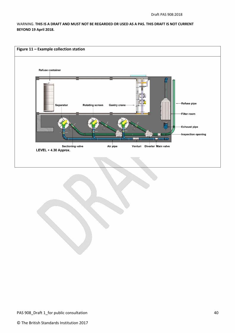
Collection stations are comprised of collection units (made up of a separator (mandatory), a compactor (optional)
and a container) and supplementary equipment including:
a) pipe diverter valve (PDV); b) filters;
c) separator; d) silencer;
e) compactor; f) odour equipment;
g) container; h) exhaust air control;
i) container conveyor; j) compressed air system;
k) cut‐off valves; l) power and control system;
m) air speed regulating system; n) isolation flanges;
o) exhausters/pumps and frequency drives; p) building requirements; and
q) non‐return valves; r) gantry crane;
s) compressor; t) ventilation system;
u) control room/office; and v) welfare facilities.
Illustrations of collection stations can be found in Figures 9 to 15.

Draft PAS 908:2018
WARNING. THIS IS A DRAFT AND MUST NOT BE REGARDED OR USED AS A PAS. THIS DRAFT IS NOT CURRENT
BEYOND 19 April 2018.
PAS 908_Draft 1_for public consultation 38
© The British Standards Institution 2017
Figure 9 – Example collection station

Draft PAS 908:2018
WARNING. THIS IS A DRAFT AND MUST NOT BE REGARDED OR USED AS A PAS. THIS DRAFT IS NOT CURRENT
BEYOND 19 April 2018.
PAS 908_Draft 1_for public consultation 39
© The British Standards Institution 2017
Figure 10 – Example Collection Station
Draft PAS 908:2018
WARNING. THIS IS A DRAFT AND MUST NOT BE REGARDED OR USED AS A PAS. THIS DRAFT IS NOT CURRENT
BEYOND 19 April 2018.
PAS 908_Draft 1_for public consultation 40
© The British Standards Institution 2017
Figure 11 – Example collection station

Draft PAS 908:2018
WARNING. THIS IS A DRAFT AND MUST NOT BE REGARDED OR USED AS A PAS. THIS DRAFT IS NOT CURRENT
BEYOND 19 April 2018.
PAS 908_Draft 1_for public consultation 41
© The British Standards Institution 2017
Figure 12 – Example Collection Station
Figure 13 – Typical Non‐Compactor type 2‐fraction collection station

Draft PAS 908:2018
WARNING. THIS IS A DRAFT AND MUST NOT BE REGARDED OR USED AS A PAS. THIS DRAFT IS NOT CURRENT
BEYOND 19 April 2018.
PAS 908_Draft 1_for public consultation 42
© The British Standards Institution 2017
Figure 14 – Example collection station waste container layout

Draft PAS 908:2018
WARNING. THIS IS A DRAFT AND MUST NOT BE REGARDED OR USED AS A PAS. THIS DRAFT IS NOT CURRENT
BEYOND 19 April 2018.
PAS 908_Draft 1_for public consultation 43
© The British Standards Institution 2017
Figure 15 – Example collection station waste container layout
For 400ND or 500ND stationary waste collection systems there are two main types of waste and air separator.
The separator types are:
a) Compactor‐type: used in collection stations with containers with a cyclone separator and compactor.
Suitable for larger network systems with extended suction distance and waste load;
b) Filter‐type: used in collection stations with containers with gravity separation for smaller systems or dry
recyclable waste where compaction is not required. Intended for smaller lower capacity systems or
recyclables with shorter suction distance and a lower vacuum pressure limit; and
c) Filter/Compactor‐type: used in collection stations with containers with gravity separation and compaction
is required.
It is possible to include different types of separator in a collection station in order to service the varied
types/fractions of waste.

Draft PAS 908:2018
WARNING. THIS IS A DRAFT AND MUST NOT BE REGARDED OR USED AS A PAS. THIS DRAFT IS NOT CURRENT
BEYOND 19 April 2018.
PAS 908_Draft 1_for public consultation 44
© The British Standards Institution 2017
4.6.2 Collection station type selection
The calculations identified at 4.3 shall be repeated. The actual values for the operation time and peak volumes
shall be used for specifying collection station components (see 4.6.3).
To establish the preliminary collection station type, the peak volume entering the separator shall be calculated in
order to determine if the preliminary collection station type has the required separation capacity. To allow a
margin for peak capacity, this calculation shall be based on four DV openings per minute:
Maximum peak volume into the separator = total chute waste volume x 4
NOTE For Fractions that are subject to increasing in volume during pipe transport (e.g. paper) a lower DV opening
frequency should be used.
4.6.3 Collection station components
NOTE Requirements for key collection station components are set out at 4.6.3. For collection station
architectural/civil/MEP requirements see Annex D and for typical collection station footprints see Annex F.
4.6.3.1 Pipe diverter valve (PDV)
If more than one fraction is to be collected through the same transport pipe, a PDV shall be used.
NOTE 2 A PDV may also be used to divert waste of the same fraction to more than one container, where required.
PDV diameter shall be the same as the transport pipe.
PDVs shall be enclosed or include safety guards.
End caps (automatic) or cut‐off valves shall be installed after the PDV to prevent smell from the open pipe ends.
A customized protective enclosure shall be provided around pipe diverter valves.
4.6.3.2 Separator – cyclone
NOTE The cyclone separates waste from the transportation air, waste falls to the lower outlet and air flows
upwards to the top outlet, through a rotating screen which separates coarse particles from the air flow.
Dependent on the compactor capacity and container connection sizing, the design waste load per system shall be
limited to 30 tonnes/day per cyclone
The cyclone shall be constructed of mild steel grade 235S that is a minimum of 6–10 mm thick, in accordance
with ASME B31.9‐2011/API 5L.
NOTE Rotating screen design should be based on overall system requirements and downstream filtration unit
The separator shall be connected to the compactor at the lower outlet with a flexible connection to avoid
vibration and allow maintenance access for the compactor.

Draft PAS 908:2018
WARNING. THIS IS A DRAFT AND MUST NOT BE REGARDED OR USED AS A PAS. THIS DRAFT IS NOT CURRENT
BEYOND 19 April 2018.
PAS 908_Draft 1_for public consultation 45
© The British Standards Institution 2017
4.6.3.3 Compactor
The compactor shall be manufactured airtight.
As waste volume increases in the separator, the compactor shall have a 50% higher theoretical throughput
measured in m3/minute, than the amount of waste entering the separator.
NOTE 1 Taking the peak volume into the separator and comparing it to the actual compaction efficiency figures,
provides the preliminary choice of compactor.
The compactor shall be fixed to the structure to prevent uplift due to negative pressure and to prevent the
compactor moving during container connection.
NOTE 2 Sufficient space should be left around the compactor for safe operation. Attention is drawn to local
regulations for required safety space to other containers, walls, columns and equipment. Specially note the hooks
for container attachment.
The compactor shall be provided with an attachment device for the container.
The compactor shall be provided with a container locking device to maintain negative pressure seal during
operation
NOTE 3 An automated container door closing device may be installed between the compactor and the Container.
4.6.3.4 Containers
The number of containers required shall be calculated, in order to store 24 hours or 48 hours total waste load.
NOTE 1 Where space allows, containers may be stacked whilst awaiting collection.
NOTE 2 Attention is drawn to local highway regulations.
NOTE 3 To calculate the number of container loads that the entire system will generate each 24 hours, multiply
the total daily volume of waste for each fraction by the average density for that fraction. This will give the total
weight for each fraction.
NOTE 4 Calculate after compaction or without compaction dependent on the fraction. See Annex A.
The container shall be manufactured airtight and designed for the system vacuum (generally ‐30 kPa).
Height to lifting hook shall be coordinated with the hook lift truck that is to be used (generally 1450 or 1570 mm
to the centre of the hook).
It shall be verified that the container is placed against the compactor/container attachment device (if used).
NOTE 4 Containers may be circular in section or rectangular. Circular containers are typically lighter than
rectangular containers with more efficient filling, rectangular containers can be more cost effective.
Container rollers shall be coordinated with the type of hook lift truck available.

Draft PAS 908:2018
WARNING. THIS IS A DRAFT AND MUST NOT BE REGARDED OR USED AS A PAS. THIS DRAFT IS NOT CURRENT
BEYOND 19 April 2018.
PAS 908_Draft 1_for public consultation 46
© The British Standards Institution 2017
Where the container is being loaded using an overhead gantry crane, ISO‐rated lifting sockets (BS ISO 1161:2016)
suitable for a container spreader shall be installed and the container rated for lifting.
NOTE 5 Sufficient space should be left around the container for safe operation. Attention is drawn to local
regulations for required safety space to other containers, walls, columns and equipment.
4.6.3.5 Container conveyor
NOTE 1 If more than one container is identified to be required, there are a number of choices to be made about
how to arrange the filling of these containers.
The limitations are also important at this stage, including those affecting frequency and timing of collections and
replacing the containers, any local issues such as proximity to residential areas, ambient temperatures, etc.
Container conveyors or PDVs, if used, shall redirect waste flow from the waste collection system to one, two or
three containers. This shall be dependent on the number of fractions of waste and number of truck movements
required to empty the containers.
NOTE 2 PDV pros and cons compared to a container conveyor include the following.
a) Pros:
1) lower cost than conveyor system;
2) simpler mechanism;
3) faster changing time;
4) automated operation.
b) Cons:
1) need more space;
2) cannot use one separator for several containers.
NOTE 3 There are three different types of container conveyors, as set out in Table .
Table 2 – Container conveyor types
Container conveyor type Commentary
Trolleys The simpler version of trolley can accommodate two containers.
Trolleys with lifting device The lifting device can move one container at a time. There is no limit to the
number of containers that can be installed.
Overhead gantry crane
(OHG)
This is used in underground and semi‐underground collection stations. It
transports containers from compactors to the “spare zone”, where it is

Draft PAS 908:2018
WARNING. THIS IS A DRAFT AND MUST NOT BE REGARDED OR USED AS A PAS. THIS DRAFT IS NOT CURRENT
BEYOND 19 April 2018.
PAS 908_Draft 1_for public consultation 47
© The British Standards Institution 2017
available to be loaded onto a truck.
OHGs use a spreader to couple and uncouple containers. This component is
usually designed to lift 20 m3 to 25 m3 containers.
Factors to consider when deciding on the use of an OGC are:
a) Physical area available for collection station – is there room for a
container conveyor or a PDV?
b) Possible access times, i.e. can the container being emptied be fetched
and returned before the remaining containers are filled?
c) Desirable access times, how often are container trucks allowed in the
area?
4.6.3.6 Air pipes and valves
NOTE 1 The air pipes are the pipes between the outlet of separator and the filter chamber including the exhausters
connection.
An expansion gap of at least 5mm shall be included between the air pipe and the venturi pipe, exhauster and
rotating screen.
NOTE 2 This avoids transference of vibrations and allows removal for maintenance.
The expansion gap shall be made airtight with heavy duty adhesive tape and EPDM sleeve fixed with hose clamps.
When suspended, air pipes shall be installed with vibration‐damping material.
The air pipes shall be a minimum thickness of:
a) 3 mm for maximum negative pressure 30 kPa; and
b) 4 mm for maximum negative pressure of 45 kPa.
NOTE 3 Non‐return valves should be placed so that safe inspection and service can be carried out.
The main valve shall be placed in the air pipe between the separator and exhauster, downstream of any
connecting pipes for different fractions and separators.
A protective net shall be placed before the main/regulating valve.
A device to monitor air speed shall be placed between the separator and the exhauster.
The venturi pipe shall be placed in the air pipe between the separator and exhauster, downstream of any
connecting pipes for different fractions and separators.

Draft PAS 908:2018
WARNING. THIS IS A DRAFT AND MUST NOT BE REGARDED OR USED AS A PAS. THIS DRAFT IS NOT CURRENT
BEYOND 19 April 2018.
PAS 908_Draft 1_for public consultation 48
© The British Standards Institution 2017
A straight length of pipe of minimum length 5 x pipe diameters shall be placed before the venturi pipe and a
straight length of pipe of minimum length 3 x pipe diameters placed after the venturi pipe.
4.6.3.7 Cut‐off valves
Cut‐off valves shall be used to isolate separators from each other.
If one separator is being used for each fraction of waste, then a minimum of one cut‐off valve shall be used per
fraction.
4.6.3.8 Air speed regulating system
NOTE 1 Air speed regulating system equipment is used to:
a) ensure that the waste arrives at the collection station by regulating the minimum air speed; and
b) reduce wear on the pipe bends and fittings by limiting the maximum air speed.
An air speed regulating system shall be included in systems with 300 m of pipe or more, or more than 2 m3 and
0.3 tonnes waste load per day.
NOTE 2 Air speed regulating equipment includes a minimum air speed sensor that can automatically start an
additional exhauster and sounds an alarm when the system is unable to maintain the right air speed.
4.6.3.9 Exhausters and vacuum pumps
Selection of exhausters shall be based on a calculation of the required air speed, waste loads and network
configuration which is unique to each supplier.
The output from the calculation shall provide the exhauster capacity on m3 air/sec, the total required negative
pressure in kPa and the required motor capacity in kW.
NOTE The calculation output will determine the number of exhausters required by the system. An extra exhauster
can reduce the effect of possible equipment failures.
Enclosure protection requirements for electrical equipment shall conform to BS EN 60529.
4.6.3.10 Non‐return valves
If there is more than one exhauster, non‐return valves shall be provided in the ducts connecting the exhausters to
prevent the exhaust air from returning to the inlet side of the exhauster.
One non‐return valve shall be provided for each exhauster.
NOTE When using vacuum pumps, non‐return valves are not necessary.

Draft PAS 908:2018
WARNING. THIS IS A DRAFT AND MUST NOT BE REGARDED OR USED AS A PAS. THIS DRAFT IS NOT CURRENT
BEYOND 19 April 2018.
PAS 908_Draft 1_for public consultation 49
© The British Standards Institution 2017
4.6.3.11 Filters
NOTE 1 Every collection system requires filters in the air pipe to separate dust and micro‐particles from the
exhaust air:
a) Non‐compacting‐type systems – have a synthetic screen filter fixed in the top of the container and this is
usually sufficient if an exhaust channel is installed; and
b) Compactor‐type systems – required filter is determined by the capacity of the collection station.
NOTE 2 Factors governing the choice of filter are:
a) waste type;
b) ambient temperature;
c) station placement in regard to surroundings;
d) cultural differences; and
e) exhaust channel opening location.
In some countries, extra filters or deodorising filters are required. Odour filters are generally required when:
a) total operation time exceeds 3 hours per day, or the longest collection process takes more than 30
minutes;
b) the air exhausted is anticipated to affect nearby residents/tenants; or
c) the average temperature during the hottest week of the year could reach 28ºC.
Filters shall be housed in an airtight chamber either prefabricated or constructed in‐situ to withstand a pressure
of 3 kPa.
Filter chamber doors shall open internally and be airtight.
Pressure monitoring of each section of the filter housing shall be provided to measure performance of the filters
and as a safety device.
NOTE 3 Use of water scrubbers as a filter should not be used, due to their performance, water usage and
maintenance issues including risk of Legionella.
Filters shall comply with BS EN 779 class G5 Coarse filters and F7 fine filters in order to remove particles down to
required percentage passing 0.4 microns.
NOTE 4 BS EN 779 is being replaced by BS EN ISO 16890‐1:2016 including Parts 1‐4 in June 2018

Draft PAS 908:2018
WARNING. THIS IS A DRAFT AND MUST NOT BE REGARDED OR USED AS A PAS. THIS DRAFT IS NOT CURRENT
BEYOND 19 April 2018.
PAS 908_Draft 1_for public consultation 50
© The British Standards Institution 2017
Figure 16 – Example Filters
Filters of activated carbon Filters of HI‐CAP & HI‐FLO
4.6.3.12 Silencer
NOTE 1 Silencers are used to reduce exhaust noise levels in order to minimize disturbances to adjacent residential
areas.
NOTE 2 Other means of sound reducing and anti‐vibration equipment might be required in sound sensitive areas.
These can include sound absorbers such as dampers and labyrinths, plus vibration rubber supports to dampen
vibrations under cyclones and exhausters.
Where carbon deodorizing filters are not used, silencers shall be installed before and after the exhausters.
Where carbon deodorizing filters are used, silencers shall be installed before the exhausters.
NOTE 2 Generally a silencer without acoustic body is installed before (upstream of) the exhausters and a silencer
with acoustic body is installed after (downstream of) the exhausters.
NOTE 3 Silencers may be installed inside or outside the exhauster room, preferably close to where the air pipe is
penetrating the exhauster room wall.
NOTE 4 Noise emission inside the collection station can be mitigated with silencers or pipe isolators.
NOTE 5 See Annex G for typical sound levels.
4.6.3.13 Odour equipment
Odour equipment shall be included where the organic fraction of the waste collected exceeds 25% by total weight
or where the ambient temperature is above 30C .
NOTE Attention is drawn to Sections 79, 80 and 82 of the Environmental Protection Act 1990.

Draft PAS 908:2018
WARNING. THIS IS A DRAFT AND MUST NOT BE REGARDED OR USED AS A PAS. THIS DRAFT IS NOT CURRENT
BEYOND 19 April 2018.
PAS 908_Draft 1_for public consultation 51
© The British Standards Institution 2017
4.6.3.14 Exhaust air pipe
NOTE 1 The exhaust air pipe is the duct downstream of the filter chamber to open air. The exhaust air pipe should
preferably be vertical and should have an angled cone at the top to increase the exhaust air exit speed. If this is
not possible, it should be directed toward a street or some other non‐sensitive area or equipped with an ejector at
the top. The exhaust channel should be high enough to minimize disturbances to the surrounding areas, whilst also
considering aesthetical appearance and acceptability. If exhaust air needs to be released at lower than optimal
height, an odour filter may be required.
The diameter of the exhaust air pipe shall be larger than the transport pipe to reduce pressure drop and minimize
over‐pressure in the filter chamber.
NOTE 2 Plan for about twice the cross section area as for the transport pipe.
For exhaust air pipes with a length of ≥ 25 m, or more than two bends, a pressure drop calculation shall be made.
The exhaust air pipe shall end with an angled cone at the top with 7º side to increase the exhaust air speed to
approximately 20 m/s.
The pipe shall exit the filter chamber flush to the wall to reduce pressure drop at the inlet of the pipe.
NOTE 3 Exhaust louver should be avoided.
The exhaust air pipe shall end no less than 3 m above the terminal roof.
NOTE 4 In normal conditions, the rain falling into the exhaust air pipe is dried by the hot air from the exhausters. In
an installation with a combination of large amounts of rain and short operation, measures should be taken to
avoid rainwater ingress.
4.6.3.15 Compressed air system
NOTE 1 A compressed air system is used to operate all valve actuators in the network and consists of:
a) a small diameter pneumatic HDPE tube installed with the transport pipe and connected to each valve
location size is dependent on compressed air calculation;
b) A compressor located in the collection station.
The compressor shall be dimensioned for the required capacity that might be placed on it during peak operation.
The compressor shall be placed together with tank, air‐dryer/cooler and drainage equipment.
NOTE 2 The compressor equipment should be purchased locally due to regulations (certification) for pressure tank,
dimensioning of cooling and drying equipment due to climate conditions.
NOTE 3 Maintenance space should be left for safe and easy inspection, service and maintenance.
The compressor shall not be placed in passages frequently used by personnel.
This compressor shall be installed in accordance with the supplier’s recommendations.

Draft PAS 908:2018
WARNING. THIS IS A DRAFT AND MUST NOT BE REGARDED OR USED AS A PAS. THIS DRAFT IS NOT CURRENT
BEYOND 19 April 2018.
PAS 908_Draft 1_for public consultation 52
© The British Standards Institution 2017
NOTE 4 The compressed air system should be placed in the exhauster room. In this case, measures should be taken
to control the climate so the equipment is not affected or damaged by poor climate conditions (e.g. high
temperature and slow air circulation).
The compressed air system shall be divided into:
a) the collection station, which constitutes one section; and
b) the compressed air pipe network, which can constitute several separate zones.
NOTE 5 The number of zones the compressed air pipe network constitutes is dependent on overall
length, pressure drop, number of actuators served and communication method.
NOTE 6 Dividing the compressed air system in this way secures operation if leakage occurs in one section of the
system.
NOTE 7 The compressed air should be dry enough not to cause any magnetic valves to freeze or corrode.
A floor drain shall be provided near enough to the compressor equipment to collect any leaked liquids.
4.6.3.16 Power supply
4.6.3.16.1 General
The Power supply in the collection station to manage the PWCS equipment shall be a 440V 3 phase supply to a
switch gear panel located in the exhauster room in accordance with BS EN 61439‐1.
Power shall be distributed to isolators adjacent to VFD’s and control panels in the collection station.
All control panels and connected equipment shall conform to:
a) 2006/95/EC Electrical Safety: The Low Voltage Directive (LVD); and
b) 2004/108/EC The Electromagnetic Compatibility Directive (EMC)
Electrical power requirements shall conform to Annex H.
NOTE 1 Attention is drawn to any applicable local standards for power distribution.
NOTE 2 In the event that power is supplied to individual equipment, the power distribution centre is not required.
NOTE 3 Any requirement for building power or substations is not included in this PAS.
NOTE 4 The redundancy of equipment in the system is dependent on the type of development and critical
operation requirements.

Draft PAS 908:2018
WARNING. THIS IS A DRAFT AND MUST NOT BE REGARDED OR USED AS A PAS. THIS DRAFT IS NOT CURRENT
BEYOND 19 April 2018.
PAS 908_Draft 1_for public consultation 53
© The British Standards Institution 2017
4.6.3.16.2 Standby Power for the Collection station
NOTE The requirement for the collection station to be included in the maintained power network should be
considered as to whether a PWCS is a critical service. For instance, hospitals or airports will typically require a 24/7
operation and would include a maintained supply or require a separate standby generator for the PWCS.
For non‐critical operations where power outages occur, they are typically of short duration (less than a day), and
the system can generally manage a reduction in collection frequency.
For longer periods before including additional standby generation, consider:
a) Runtime of the systems.
b) Reduced requirement for collection of waste if the whole development is affected as waste generation
is linked to normal operations.
c) Possibility of manual collection.
d) For larger developments, it is possible to include a power supply from two substations, or include a
cable connection for a temporary mobile generator if one has not already been included in the main
supply substation.
The critical equipment for the PWCS shall be:
a) Exhausters / Vacuum pumps – generally number of exhausters should be based on n+1
redundancy;and
b) Air Compressors in the collection station are not generally seen as requiring additional spare units as
the system uses relatively low volumes compared to the pressure tank capacity and temporary
compressors are readily available. The decision to include additional capacity is project dependent.
NOTE Service level agreements with planned maintenance avoid the requirement for extensive
redundancy in equipment.
4.6.3.17 Control system
4.6.3.17.1 General
The programming language used in the control system shall conform to BS EN 61131‐3.
NOTE 1 The control system runs the emptying process of the system.
It includes the following components:
a) exhauster control centre;
b) variable frequency drive controllers supplied motor control centre;

Draft PAS 908:2018
WARNING. THIS IS A DRAFT AND MUST NOT BE REGARDED OR USED AS A PAS. THIS DRAFT IS NOT CURRENT
BEYOND 19 April 2018.
PAS 908_Draft 1_for public consultation 54
© The British Standards Institution 2017
c) air speed regulating system controls;
d) compactor control; and
e) electric supply controls.
The configuration of the control system is governed by the required capacity of the PWCS.
NOTE 2 The control system starts, controls, and monitors the automated collection process. The control system
uses a data network to communicate between all valves in the pipe network and the equipment in the collection
station.
NOTE 3 The data network is placed in HDPE conduits along the pipe network, and is used to control all the valves
at the inlet points.
Emptying can be triggered by:
a) predefined times for emptying of all the inlets.
b) predefined times for the most frequently full ,
c) operator controlled manual emptying; and
d) level indicators in the storage pipes.
How the control system is to act on level signals is specified for each individual installation.
NOTE 4 In order to make the PWCS fully automatic and rational, it is important to provide a centralized logic
making the decisions based on efficient algorithms and parameters for the emptying process.
Normally, the plant is unmanned, but all mechanical equipment, motors and electrical parts need regular
maintenance. The control system calls for attendance by giving an alarm signal. The alarms should be classified
into two categories:
a) general alarms, which do not need immediate attention (e.g. if an air inlet valve does not open, the
emptying process may continue to the next branch); and
b) critical alarms, which prevent the emptying process to continue (e.g. if the refuse level in the cyclone is
above the limit, the system is shut down and the problem solved before the emptying process may
continue).
The control system is connected to the internet for monitoring and rectification of alarms. This also enables a wide
range of reports and data to be collated and sent to clients for information and billing.
The control cabinet dimensions are referenced in Annex D (D.3).
4.6.3.17.2 Control system extent
The control system shall consist of the following major subsystems and parts:

Draft PAS 908:2018
WARNING. THIS IS A DRAFT AND MUST NOT BE REGARDED OR USED AS A PAS. THIS DRAFT IS NOT CURRENT
BEYOND 19 April 2018.
PAS 908_Draft 1_for public consultation 55
© The British Standards Institution 2017
a) electric control centre cabinet (ECC);
b) compactor control box (CCB) (See Figure 17);
c) control box (CB);
d) valve control box (controlling all valves in the inlet net) (VCB); and
e) valve repeater box (booster box for communication and power distribution) (VRB).
NOTE 1 The ECC distributes electrical power to machines and sends control signals (e.g. valve operations) and
receives status signals from limit switches, etc.
The ECC shall communicate with valve room equipment throughout the PWCS.
The VCB shall be able to control all types of valves in the inlet network.
A remote control console shall give the personnel at the building management system centre provisions to gain
control for the plant.
The remote site shall communicate with the plant over the public telephone network, or over IP connection. The
communication shall be executed either from a hand held device or a PC and allow for a variety of devices for
connection. It shall be possible to control all functions of the PWCS and monitor all status remotely.
The connectivity of the system shall cover the building management system (BMS) and the possibility for web‐
based connection, enabling the owners of the PWCS to have live feedback of the performance of the system.
The system shall have a report function for the owner to create reports for data gathering and performance
monitoring.
Unless shown or indicated otherwise, the electrical supply shall be designed for alternating current, 3 phase,
415/230 volt, 50/60Hz.
NOTE 2 Attention is drawn to applicable local authority regulations.
Figure 17 – Compactor‐ control box

Draft PAS 908:2018
WARNING. THIS IS A DRAFT AND MUST NOT BE REGARDED OR USED AS A PAS. THIS DRAFT IS NOT CURRENT
BEYOND 19 April 2018.
PAS 908_Draft 1_for public consultation 56
© The British Standards Institution 2017
4.6.3.17.3 Electronic control centre cabinet (ECC)
NOTE 1 The ECC is the base unit of the control system. All sub‐units and valve control equipment are electrically
connected to it.
The ECC shall house a touch screen operator panel in accordance with BS EN 60529. The screen size shall not be
less than 38 centimetres. The operator panel shall have the operational performance to avoid any additional
operator interface like SCADA systems unless specified by the end user
Control power distribution to the valve control modules shall be provided from the ECC as well as to all control
units in the control system.
The ECC shall house a programmable logic controller (PLC) system for the operation of the plant equipment. The
PLC shall be of industrial type with Windows software embedded.
NOTE 2 Energy consumption of the equipment is recorded by the ECC unit PLC.
Small power supplies shall convert the mains AC power to 24V DC and 48 VAC, used for operation of small relays
and logic circuits.
NOTE 3 All operations are controlled from the PLC program in the ECC. The operator panel gives the operator
access to control all connected equipment.
4.6.3.17.4 Operator's panel
On the front door of the ECC there shall be an operator's panel containing switches for manual control, lamp
indications and an alphanumeric operator's terminal with a fluorescent text display and a keyboard.

Draft PAS 908:2018
WARNING. THIS IS A DRAFT AND MUST NOT BE REGARDED OR USED AS A PAS. THIS DRAFT IS NOT CURRENT
BEYOND 19 April 2018.
PAS 908_Draft 1_for public consultation 57
© The British Standards Institution 2017
NOTE 1 The operator’s panel will be used in exceptional cases to check the status of machines and valves. It may
also be used to control objects of the plant and to set parameters for the PLC system.
Pneumatic instruments shall be located above the operator's panel so that the operator can see the immediate
response to their operations (e.g. with respect to the airspeed, etc).
NOTE 2 The operator's panel is not meant to be used for normal automatic or manual operation (the PC is), rather
it is meant to be used in situations where the computer system is inoperable for some reason.
4.6.3.17.5 ECC and remote control processor (RCP) operator's interface
The ECC shall master all activities for the control system.
NOTE At least a 486 compatible PC computer should be used.
The open architecture of the PC makes it easy to find accessories, spare parts and preventive and corrective
maintenance service.
The PC keyboard and colour monitor form the operator's interface to the system. The system displays menus and
messages for status and alarms to the operator. From the keyboard the operator enters commands to control the
system functions.
The control system may optionally be equipped for remote control. Using the public telephone network it is
possible to phone the plant from a service centre. All operator functions are also possible from a remote site.
The operator may, after a password verification test is passed, take full control of the plant including possibilities
to inspect status and the system log list, acknowledge alarms and operate motors and valves, etc.
It shall be possible to update software from a remote site. The same type of computer shall be used at the remote
site (remote control processor (RCP)).
4.6.3.17.6 Control boxes (CBs)
The ECC shall be expanded by distributed CBs.
NOTE CBs should be placed close to the equipment they are controlling and equipped with distributed IO terminals
The CBs do not require any operator manual control interface.
CBs shall run on 24VDC.
The ECC shall have full control of all connected inputs and outputs (IO).
CBs shall be IP54 rating as a minimum.
4.6.3.17.7 SV control unit
NOTE 1 Control equipment in the valve rooms is needed to control operation of valves in the outer pipe system.

Draft PAS 908:2018
WARNING. THIS IS A DRAFT AND MUST NOT BE REGARDED OR USED AS A PAS. THIS DRAFT IS NOT CURRENT
BEYOND 19 April 2018.
PAS 908_Draft 1_for public consultation 58
© The British Standards Institution 2017
Valve room boxes shall be designed for controlling and monitoring one valve each. They shall be equipped with
appropriate electronic circuitry and a communication channel to communicate with the central computer system
in a serial message format.
If condensation takes place, the equipment shall be mounted in an IP54 rated enclosure to protect it from any
moisture.
NOTE 2 If the environment is dry, the equipment may be mounted directly on a steel plate.
NOTE 3 Due to different operation requirements there are different types of valve room boxes.
4.6.3.17.8 Communication to valve rooms
NOTE 1 the requirements listed in 4.6.3.17.9 are based on a basic communication protocol that is centrally linked
for suitable for remotely located valves and does not require any additional power supply at the valve locations.
There are other forms of communication carrier are available such as:
a) Fibre optic; and
b) TCP/IP.
Valve room boxes shall be connected in parallel to a communication cable (i.e. the control cable). The
communication cable shall be RX 485 compliant for the following:
a) Power supply, which shall be low voltage from safety aspect and operational reliability.
b) The control system, which shall allow for multiple channels of communication networks.
c) Long distance or many valves in the network, which shall require VRB to ensure power and
communication characteristics.
The number of valves in a single network shall not exceed 100.
NOTE 2 This number could be less depending upon control system design.
NOTE 3 Communication with valve control unit is initiated by the ECC unit and all valves are considered remote
slaves to the controller in the ECC.
NOTE 4 It is important that the valve controller is operated as slave units to maintain a safe operating protocol.
4.6.3.17.9 AV‐DV control system
The control system shall be programmed to continuously interrogate all valve rooms in a continuous scan.
NOTE 1 There might be more than one channel and the control system communicates on these channels
simultaneously.

Draft PAS 908:2018
WARNING. THIS IS A DRAFT AND MUST NOT BE REGARDED OR USED AS A PAS. THIS DRAFT IS NOT CURRENT
BEYOND 19 April 2018.
PAS 908_Draft 1_for public consultation 59
© The British Standards Institution 2017
Communication speed shall be selected so that it is possible for the central system to collect status from 20 valve
rooms per second. For valves that have received open order the interrogation scan shall collect status from more
than 20 valve rooms per second.
It shall be possible to use up to four communication channels.
NOTE 2 Each channel may communicate to a maximum of 126 valve rooms. However there might be restrictions
due to cable length, etc.
4.6.3.17.10 Software
The PLC and operator panel shall be equipped with the latest programming software. The programming language
shall conform to BS 61131‐3.
NOTE In the event that the system supplier has proprietary software that controls how the system runs, a user
license should be issued to the operator along with an undertaking of responsibility in the event of software
malfunction.
Software shall be programmed as per the agreed project approved functional specification.
4.6.3.17.11 Operating modes – Fault tolerant system
The control system shall be designed to enable waste collection in situations when some control equipment is
inoperable.
NOTE 1 In such a case, it should be possible to collect the waste although it might require some more time and
manual interaction. To achieve this there are a number of operating modes.
NOTE 2 The Central PC is normally operating for automatic emptying, however it may be switched to manual
operation mode to enable for example emptying of a single gravity chute.
NOTE 3 The initiation of the emptying process can be made from time‐based emptying, level‐based emptying, or
from the self‐learning system, predicting the filling degree of the inlet based on the historical recorded data.
NOTE 4 The PC may be used to start automatic emptying by remote control or operate all equipment remotely
from any location within the system, through the remote control interface.
NOTE 5 Manual operation should have built‐in soft safety features to avoid any hazardous operation by unskilled
operators.
4.6.3.18 Emergency and safety system
4.6.3.18.1 General
All machinery shall be designed with emergency stops and safety interlocking functions in both the mechanical
and the electrical system. Access and inspection doors/hatches to areas with risk of personnel or machine
damage shall be monitored or bolted so that they cannot be opened without specially designed tools.

Draft PAS 908:2018
WARNING. THIS IS A DRAFT AND MUST NOT BE REGARDED OR USED AS A PAS. THIS DRAFT IS NOT CURRENT
BEYOND 19 April 2018.
PAS 908_Draft 1_for public consultation 60
© The British Standards Institution 2017
NOTE The emergency stop chain(s) and system is completely standalone and parallel to the control system. It is
sufficiently and continuously monitored for its status by the control system.
4.6.3.18.2 Safety class
The electrical system shall be designed for a safety class of PL E.
NOTE See BS EN 60204, BS EN 418, and BS EN 954‐1.
4.6.3.19 Heat generation
The generated heat from the equipment shall be:
a) for the EEC, less than 500 W;
b) for the electrical power centre (EPC), less than 500 W;
c) for variable frequency drives, no more than 2% of installed power; and
d) for exhausters, no more than 8% of installed power.
NOTE 1 If installing the EPC/motor control centre (MCC) in the exhauster room, the heat generated from the
exhausters should be considered. The exhausters and exhauster connection pipe generate approximately 8% of
installed power as heat in the room.
NOTE 2 Heat generation figures apply only during expected system operation periods which should be taken into
account when selecting the air conditioning requirements in the exhauster room.
4.6.3.20 Valve network
The data network for the valves shall be dependent on the method of communication.
4.7 Step 6 – Optimize solution
COMMENTARY ON 4.7.
Steps 1–5 provide enough data to be able to create a design and specify items to be ordered, and develop a
control and operation programme and therefore design a control system.
4.7.1 General
Following the design of the system, a full review and design optimization shall take place. This shall be conducted
as part of a quality assurance and value engineering process by competent persons.
NOTE The full review and design optimization should aim to solve any outstanding problems, reduce costs where
possible, whilst improving the PWCS functionality and quality.
4.7.2 Preliminary design
Following design optimization, the pipe system shall be dimensioned.

Draft PAS 908:2018
WARNING. THIS IS A DRAFT AND MUST NOT BE REGARDED OR USED AS A PAS. THIS DRAFT IS NOT CURRENT
BEYOND 19 April 2018.
PAS 908_Draft 1_for public consultation 61
© The British Standards Institution 2017
NOTE The data gathered is based on the minimum required specification for the design and development of a
PWCS. Therefore, the preliminary design based on these requirements, could be enhanced. The adjustments often
occur following discussions with the client, where variables other than performance might become a priority.
Some of the more common issues that might affect changes to the preliminary design are set out in Table .
Table 3 – common issues affecting changes to the preliminary design
Area Description
Waste type definition Initial estimates might have been based on assumptions. As the project
progresses, the type and volumes of waste become more defined.
Optimal operation times In addition to performance, other factors to be considered are:
a) noise restrictions;
b) waste collection vehicle access restrictions;
c) traffic considerations for waste collection vehicles;
d) odour restrictions; and
e) local bylaws and other legal restrictions.
Most economical pipe The pipe size identified is based on performance requirements that contain a
margin of safety, and thus likely to be over‐dimensioned.
Reassessing the pipe system layout could lead to the following changes:
identification of a shorter pipe, a smaller pipe, a different type of pipe.
Service intervals Equipment should be serviced on a regular basis.
The system should be looked at from an accessibility point of view for items that
require regular servicing and future component replacement.
Planning for higher capacity could reduce the frequency of service required and
thus the service and replacement costs.
Operational economics An operational cost projection might be required at the clients’ request.
One key aspect to consider is the future planned development of the area within
which the collection station is situated. If, for example, there are known plans for
further development of the surrounding area, consider placement of the
collection station for servicing additional development(s).

Draft PAS 908:2018
WARNING. THIS IS A DRAFT AND MUST NOT BE REGARDED OR USED AS A PAS. THIS DRAFT IS NOT CURRENT
BEYOND 19 April 2018.
PAS 908_Draft 1_for public consultation 62
© The British Standards Institution 2017
5 Procurement/installation
5.1 General
The PWCS shall be provided as a whole system by competent persons.
NOTE 1 This PAS is the recognized standard for the design and construction of a PWCS. The specification defines a
common standard for all manufacturers, designers and users of this system, to give owners confidence that the
system has been developed with the following key features as a minimum:
a) secure – minimizing risk for personal injury;
b) efficient – minimizing operation costs and maximizing collection performance;
c) durable – minimizing repair and maintenance and maximizing expected lifetime;
d) economically competitive – minimizing production and installation costs;
e) environmentally friendly – minimizing negative impacts on the environment.
Within Clause 4 and Clause 5, there are identified design requirements to be followed in order to secure a
functioning, durable and safe PWCS as defined by this PAS.
NOTE 2 It is not recommended to procure PWC Systems as individual components, as this increases the points of
responsibility and the risk of reduced functionality. A system implementation using several suppliers makes it
impossible for any one of them to take full operational responsibility, and that must then be taken by the
purchasing organization.
5.2 Scope of works
5.2.1 General
NOTE 1 The instruction to tenderers and scope of works for each project should determine the required details
needed to plan and design a PWCS. This should include a project description outlining the development, including
its location, size, type of functional areas (commercial, residential, educational, medical, etc.), anticipated
population/visitor numbers and waste streams to be handled (source separated and/or mixed).
The PWCS shall be capable of conveying the required waste/recyclable fractions from waste inlets around the
development to the collection station. This shall be automatic and with minimal operator involvement.
The PWCS shall consist of waste inlets (the number of which are calculated per project, see 4.4), which are
connected to the pipe network. The PWCS shall then transport the deposited waste/recyclables via the pipe
network using air to the waste collection station. Waste shall be compacted and stored in the collection station,
prior to transportation to a recycling/waste management facility for treatment/disposal.
Exhaust air from the PWCS shall be filtered prior to discharge in order to mitigate against the potential for dust
and odour escape.

Draft PAS 908:2018
WARNING. THIS IS A DRAFT AND MUST NOT BE REGARDED OR USED AS A PAS. THIS DRAFT IS NOT CURRENT
BEYOND 19 April 2018.
PAS 908_Draft 1_for public consultation 63
© The British Standards Institution 2017
The system supplier responsibilities shall include a full design, build and operation/maintenance package.
NOTE 2 This could consist of the complete design, manufacture, conveyance to site, off‐loading, storage,
protection, installation, testing, commissioning, verification, spare parts, client training, documentation, product
support and warranties of all mechanical and electrical work associated with the PWCS.
The system supplier shall liaise and coordinate with the main client until the PWCS is operational.
NOTE The system supplier should also consult with, as a minimum:
planners;
utilities and services;
designers/contractors;
infrastructure;
civils and structural contractors;
general contractor;
executive architect; and
design architects.
This is to ascertain requirements for the PWCS throughout its lifecycle.
5.2.2 Programme of works
The system shall apply to the clients programme of works.
NOTE 1 The client specifies a programme of works. This usually includes as a minimum, the following stages 2):
a) strategic definition – business case and core project objectives;
b) preparation and brief – project objectives and aspirations, feasibility studies;
c) concept design – prepare concept design, including outline proposals, outline specifications and
preliminary costs;
d) developed design – prepare developed design, including coordinated and updated proposals, outline
specifications, costs and project strategies;
e) technical design (including tender documentation) – prepare technical design in accordance with project
strategies to include all architectural, structural and building services information, specialist subcontractor
design and specifications; and
2) See RIBA Plan of Work 2013.
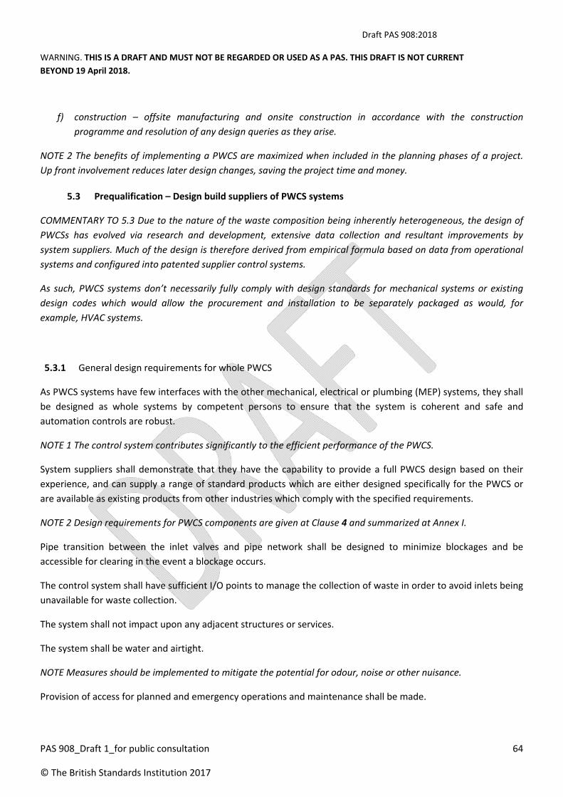
Draft PAS 908:2018
WARNING. THIS IS A DRAFT AND MUST NOT BE REGARDED OR USED AS A PAS. THIS DRAFT IS NOT CURRENT
BEYOND 19 April 2018.
PAS 908_Draft 1_for public consultation 64
© The British Standards Institution 2017
f) construction – offsite manufacturing and onsite construction in accordance with the construction
programme and resolution of any design queries as they arise.
NOTE 2 The benefits of implementing a PWCS are maximized when included in the planning phases of a project.
Up front involvement reduces later design changes, saving the project time and money.
5.3 Prequalification – Design build suppliers of PWCS systems
COMMENTARY TO 5.3 Due to the nature of the waste composition being inherently heterogeneous, the design of
PWCSs has evolved via research and development, extensive data collection and resultant improvements by
system suppliers. Much of the design is therefore derived from empirical formula based on data from operational
systems and configured into patented supplier control systems.
As such, PWCS systems don’t necessarily fully comply with design standards for mechanical systems or existing
design codes which would allow the procurement and installation to be separately packaged as would, for
example, HVAC systems.
5.3.1 General design requirements for whole PWCS
As PWCS systems have few interfaces with the other mechanical, electrical or plumbing (MEP) systems, they shall
be designed as whole systems by competent persons to ensure that the system is coherent and safe and
automation controls are robust.
NOTE 1 The control system contributes significantly to the efficient performance of the PWCS.
System suppliers shall demonstrate that they have the capability to provide a full PWCS design based on their
experience, and can supply a range of standard products which are either designed specifically for the PWCS or
are available as existing products from other industries which comply with the specified requirements.
NOTE 2 Design requirements for PWCS components are given at Clause 4 and summarized at Annex I.
Pipe transition between the inlet valves and pipe network shall be designed to minimize blockages and be
accessible for clearing in the event a blockage occurs.
The control system shall have sufficient I/O points to manage the collection of waste in order to avoid inlets being
unavailable for waste collection.
The system shall not impact upon any adjacent structures or services.
The system shall be water and airtight.
NOTE Measures should be implemented to mitigate the potential for odour, noise or other nuisance.
Provision of access for planned and emergency operations and maintenance shall be made.

Draft PAS 908:2018
WARNING. THIS IS A DRAFT AND MUST NOT BE REGARDED OR USED AS A PAS. THIS DRAFT IS NOT CURRENT
BEYOND 19 April 2018.
PAS 908_Draft 1_for public consultation 65
© The British Standards Institution 2017
5.3.2 Design development
5.3.2.1 General
The level of detail included at the stages of design development shall be in accordance with The Building Services
Research and Information Association (BSRIA) guide, A Design Framework for Building Services as a minimum.
NOTE As the design progresses, the following will be required from the system supplier at each of the stages.
5.3.2.2 Concept design
The system supplier shall use the scope of works and any other available project information to develop a concept
design with accompanying sketches, outlining the proposed development solution using the PWCS.
5.3.2.3 Developed design
The system supplier shall develop comprehensive schematic drawings for the pipe network, identifying all waste
inlets, valves, air inlets, waste collection station and any other plant and equipment.
5.3.2.4 Technical design
The system supplier shall develop detailed pipe and equipment schematics for the complete PWCS, as well as
detailed equipment and distribution layouts and sections based on final equipment selections.
5.3.2.5 Working drawings
The system supplier shall provide working drawings.
5.3.2.6 Documentation
The system supplier shall compile and submit operation and maintenance manuals, testing and commissioning
record data and reports, certified drawings, as built drawings, etc.
5.3.3 Design life
The system shall have a stated design life expectancy.
Specific elements, which are consumables such as filters, shall be identified and shall be the subject of a planned
maintenance programme for replacement.
NOTE 1 The complete system should usually be designed for an expected service life of 30 years.
The system shall be constructed to provide a target service life of 30 years based on standard operation within
design parameters and with proper maintenance in accordance with suppliers’ recommendations. . Major
components will be provided with guarantees which will depend on the type of equipment.
NOTE 2 It is expected that a major refurbishment would take place 15 years after installation.
Major components are generally:
Draft PAS 908:2018
WARNING. THIS IS A DRAFT AND MUST NOT BE REGARDED OR USED AS A PAS. THIS DRAFT IS NOT CURRENT
BEYOND 19 April 2018.
PAS 908_Draft 1_for public consultation 66
© The British Standards Institution 2017
1) Pipework including any static component of the pipe network
2) Valve bodies
3) Cyclone
4) Compactors
5) Compressor
6) Control panels (except components)
Major maintenance at 15 years might include:
1) New valve plates
2) Refurbishment of high wear areas in bends
3) New compactor plates / hydraulic pumps
4) Exhauster fan blades
Other items will be replaced as part of planned maintenance dependent on usage patterns, such as:
1) Control sensors
2) Actuators
3) Filters
4) Bearings
The timescales provided above can be considerably reduced where the installation is operated outside the
expected parameters for types of waste, quantity of wastes, excessive negative pressure and or maintenance is
not carried out in accordance with suppliers’ recommendations.
The PWCS supplier shall provide a warranty that the system will perform as specified for an agreed period of time,
if the system is operated within normal design load and is properly maintained in accordance with supplier
recommendations, which is backed up by product guarantees for individual supplier and third party supplier
components.
5.3.4 Materials
NOTE The materials to be used for the development of a PWCS should be tried and tested, and designed to
withstand the stresses imposed by the working and ambient conditions without deterioration or premature failing
affecting the efficiency and reliability of the PWCS.
Mild steel components shall conform to ASME B31.9‐2011/API 5L.
5.3.5 Environmental performance
The system design shall conform to any environmental standards specified by the project brief.
NOTE 1 Specific standards will be nominated as part of the project brief and are likely to include LEED or BREEAM
and ISO standards.

Draft PAS 908:2018
WARNING. THIS IS A DRAFT AND MUST NOT BE REGARDED OR USED AS A PAS. THIS DRAFT IS NOT CURRENT
BEYOND 19 April 2018.
PAS 908_Draft 1_for public consultation 67
© The British Standards Institution 2017
The PWCS can contribute to LEED BREEAM credits by providing a waste collection system that can:
a) facilitate the reduction of waste generated by building occupants that is hauled to and disposed of in
landfills or incineration facilities.
b) facilitate the reduction of ongoing waste and toxins generated by building occupants and building
operations that are hauled to and disposed of in landfills or incineration facilities.
c) establish minimum source reduction and recycling program elements and quantify current waste stream
production volume.
d) provide dedicated space(s) to cater for the segregation and storage of operational recyclable waste
volumes generated by the assessed building/unit, its occupant(s) and activities, where the dedicated space
is:
1) clearly labelled, to assist with segregation, storage and collection of the recyclable waste streams;
2) accessible to building occupants/facilities operators for the deposit of materials and collections by
waste management contractors;
3) of a capacity appropriate to the building type, size, number of units (if relevant) and predicted
volumes of waste that will arise from daily/weekly operational activities and occupancy rates;
e) provide static waste compactor(s) or baler(s); situated in a service area or dedicated waste management
space.
NOTE 2 In addition to meeting sustainability credits, the PWCS can minimise the space requirements for waste
storage, thus releasing more saleable/leasable area within a development.
NOTE 3 The system design should:
a) avoid contributing to ozone depletion, global warming, air and water pollution and non‐renewable
resource depletion;
b) avoid sources of ionizing and electromagnetic radiation and any design features associated with sick
building syndrome;
c) maximize design opportunities for waste minimisation and recycling;
d) consider sustainability in its design, including:
1) adherence to any nominated project‐specific standards, such as LEED, BREEAM or other green
building codes;
2) collection station layout;
3) selection of materials;
4) insulation;

Draft PAS 908:2018
WARNING. THIS IS A DRAFT AND MUST NOT BE REGARDED OR USED AS A PAS. THIS DRAFT IS NOT CURRENT
BEYOND 19 April 2018.
PAS 908_Draft 1_for public consultation 68
© The British Standards Institution 2017
5) energy efficient and water efficient plant, appliances, fixtures and fittings;
6) heat recovery systems.
5.4 Electrical control and monitoring system
5.4.1 General – System operation
The system supplier shall implement a single, comprehensive and fully integrated electrical control and
monitoring system which conforms to:
a) BS EN 61131‐3; and
b) BS EN‐60204‐1.
The electrical control and monitoring system shall be dimensioned for voltage and frequency: 230/400 VAC, 50
Hz.
NOTE 1 Attention is drawn to:
a) Machinery EU‐directive 98/37/EC [5];
b) Low Voltage Directive (LVD) [6], EU‐directive 73/23/EEC [7] and amendment 93/68/EEC [8]; and
c) Electromagnetic Compatibility, EU‐directive 89/336/EEC [9] amended by 92/31/EEC [10] and
93/68/EEC [8] concerning EMC.
The work to be performed shall include all materials and equipment required for a complete operating
installation.
NOTE 2 For operation and maintenance, see Annex K
5.5 Installation
5.5.1 General
The installation of the transport pipeline and ancillaries shall be in accordance with BS EN 805:2000, Section 10
relating to the installation of pipeline.
5.5.2 Quality assurance and control
The system supplier shall implement a quality assurance and control system.
Welding of transport pipe joints shall be carried out by certified welders to Section IX of the ASME Boiler and
Pressure Vessel Code (BPVC), welding procedure specification WPS [NR2].

Draft PAS 908:2018
WARNING. THIS IS A DRAFT AND MUST NOT BE REGARDED OR USED AS A PAS. THIS DRAFT IS NOT CURRENT
BEYOND 19 April 2018.
PAS 908_Draft 1_for public consultation 69
© The British Standards Institution 2017
5.5.3 Testing and commissioning
5.5.3.1 Test of system performance and function
The final test of the system shall be conducted in three stages:
a) visual inspection, including a check of all PWCS components according to this PAS for:
1) design;
2) completeness of mechanical, electrical and PLC elements;
3) correct installation;
4) material, finish, and surface;
5) tolerance, anchoring and fixing; and
6) accessibility and serviceability;
b) manual function test, including:
1) check of all mechanical functions;
2) test of main components individually; and
3) test run of the system in manual mode;
c) automatic function test, including:
1) check of all automatic functions;
2) system test run in automatic mode; and
3) system test run in emergency mode.
NOTE Tests can be made separately or at the same time.
A detailed acceptance report shall be produced for all tests conducted.
All tests shall be performed according to the system supplier’s procedures.
5.5.3.2 Commissioning
The commissioning of the system shall be carried out in accordance with a commissioning procedure which
shall include as a minimum the following (see Annex J for typical outline):
air leakage test in accordance with ASME B31.9 to test for leakage in the pipe network;
NOTE typically a test of 0.2 bar with no pressure drop over 1 hour will be sufficient to demonstrate
compliance
airspeed measurement with the regulating parameters set accordingly prior to commissioning;
normalization of values according to the system supplier’s standard (typically air pressure 101.3 kPa
and 0 °C);
NOTE Acceptable variance is < 1.5 m/s prior to commissioning.
tests/ methods to reduce energy usage.
confirmation of the capacity of the system; and

Draft PAS 908:2018
WARNING. THIS IS A DRAFT AND MUST NOT BE REGARDED OR USED AS A PAS. THIS DRAFT IS NOT CURRENT
BEYOND 19 April 2018.
PAS 908_Draft 1_for public consultation 70
© The British Standards Institution 2017
confirmation that the system availability complies with project requirements expected.
Prior to commissioning, air leakage shall be checked with one section valve open and using one exhauster
less than normally required.
The air leakage shall be less than 10% of the normalized value. The acceptance form shall be completed and
signed by the commissioner prior to commissioning.

Draft PAS 908:2018
WARNING. THIS IS A DRAFT AND MUST NOT BE REGARDED OR USED AS A PAS. THIS DRAFT IS NOT CURRENT
BEYOND 19 April 2018.
PAS 908_Draft 1_for public consultation 71
© The British Standards Institution 2017
Annex A (normative)
Waste densities
Data provided by ENVAC (2016).
Table A.1 – Waste densities
Fraction Producer Waste type Sub‐classification Density (kg/m3) Maximum storage
section height (m) Min Max Avg
Mixed
Residential Household Light (US, Canada,
Northern Europe)
40 150 95 2.5
Residential Household Medium 150 240 195 2.5
Residential Household Heavy (E. Europe,
Asia)
240 350 295 1.5
Airport Commercial From terminal only 150 240 195 2.5
Airport Commercial From terminal and
cabin
240 350 295 1.5
Amusement
Park
Commercial 150 240 195 2.5
Exhibition Hall Commercial 40 150 95 2.5
Shops Commercial Light (US, Canada,
Northern Europe)
40 150 95 2.5
Shops Commercial Medium 150 240 195 2.5
Office Commercial Medium 150 240 195 2.5
Office Commercial Heavy 240 350 295 1.5
School Public Sector Medium 150 240 195 2.5
Restaurant Commercial Medium (US, Canada,
Northern Europe)
150 240 195 2.5
Restaurant Commercial Heavy (Eastern
Europe, Asia)
240 350 295 1.5
Paper
Residential Household,
loose
Light 40 150 95 2.5
School Public sector,
loose
Medium 150 240 195 2.5
Shops Commercial,
loose
Heavy 240 350 295 1.5
Office Commercial,
packaged
Medium (c) 150 240 195 2.5
Office Commercial,
packaged
Heavy 240 350 295 1.5
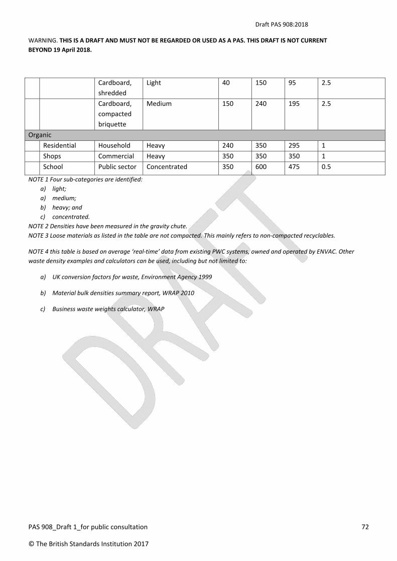
Draft PAS 908:2018
WARNING. THIS IS A DRAFT AND MUST NOT BE REGARDED OR USED AS A PAS. THIS DRAFT IS NOT CURRENT
BEYOND 19 April 2018.
PAS 908_Draft 1_for public consultation 72
© The British Standards Institution 2017
Cardboard,
shredded
Light 40 150 95 2.5
Cardboard,
compacted
briquette
Medium 150 240 195 2.5
Organic
Residential Household Heavy 240 350 295 1
Shops Commercial Heavy 350 350 350 1
School Public sector Concentrated 350 600 475 0.5
NOTE 1 Four sub‐categories are identified:
a) light;
a) medium;
b) heavy; and
c) concentrated.
NOTE 2 Densities have been measured in the gravity chute.
NOTE 3 Loose materials as listed in the table are not compacted. This mainly refers to non‐compacted recyclables.
NOTE 4 this table is based on average ‘real‐time’ data from existing PWC systems, owned and operated by ENVAC. Other
waste density examples and calculators can be used, including but not limited to:
a) UK conversion factors for waste, Environment Agency 1999
b) Material bulk densities summary report, WRAP 2010
c) Business waste weights calculator, WRAP

Draft PAS 908:2018
WARNING. THIS IS A DRAFT AND MUST NOT BE REGARDED OR USED AS A PAS. THIS DRAFT IS NOT CURRENT
BEYOND 19 April 2018.
PAS 908_Draft 1_for public consultation 73
© The British Standards Institution 2017
Annex B (normative)
Waste types accepted by a PWCS
Table B.1 – Waste types accepted by a PWCS
Paper Cardboard Cans Glass Rigid
plastics
Plastic
film/Polystyrene
Textiles/linen Food Garden Bulky
items/C&D
Waste
Clinical
waste
Hazardous
waste
WEEE Liquid
waste
Residential YES C YES C YES C YES YES YES NO NO NO NO NO
Offices YES C YES C YES C YES YES NO NO NO NO NO NO
Restaurants YES C YES C YES C NO YES NO NO NO NO NO C
Catering facilities YES C YES C YES C NO YES NO NO NO NO NO C
Public realm YES NO YES C YES C YES YES YES NO NO NO NO NO
Retail YES C C C YES C YES YES NO NO NO NO NO NO
Health‐
care/hospitals
YES C YES C YES C Linen OK YES NO NO C NO NO NO
Airports YES C YES C YES C NO YES NO NO NO NO NO NO
C = Conditional to quantities, system design and processing requirements

Draft PAS 908:2018
WARNING. THIS IS A DRAFT AND MUST NOT BE REGARDED OR USED AS A PAS. THIS DRAFT IS NOT CURRENT
BEYOND 19 April 2018.
PAS 908_Draft 1_for public consultation 74
© The British Standards Institution 2017
Annex C (normative)
DV room and chamber Sizes
DV room sizes for DV/AV in buildings or in chambers for outdoor inlets shall be not less than the minimum areas
shown in Table C.1.
NOTE It is not always necessary to provide an AV with every DV therefore some DV rooms/chambers require less
space if there only a DV required.
Table C.1 – Minimum areas for DV rooms and chambers
Indoor DV room (m2)
1 fraction 2 fractions 3 fractions
With air inlet valve 6 9 12
Without air inlet valve 5 7 10
Minimum area required for outdoor DV chamber (m2)
With air inlet valve 8 11 13
Without air inlet valve 8 11 13

Draft PAS 908:2018
WARNING. THIS IS A DRAFT AND MUST NOT BE REGARDED OR USED AS A PAS. THIS DRAFT IS NOT CURRENT
BEYOND 19 April 2018.
PAS 908_Draft 1_for public consultation 75
© The British Standards Institution 2017
Annex D (normative)
Architectural/civil/MEP requirements
D.1 Collection station
The requirements in Table D.1 shall be allowed for in the collection station building design and supplied and
installed under the scope of the general contractor.
Table D.1 – Collection station requirements
Component Requirements
Filter room Where the filter room is installed in situ by general contractor the following shall
be provided.
o Reinforced concrete dividing wall with roof slab to withstand 3 kPa
pressure with penetration for fitting filter frame.
o Steel door to each filter section 700 x 2100 mm opening internally with
EPDM gasket.
o Epoxy floor finish.
o Lighting.
NOTE Cooling is not required.
Where Installations include prefabricated filter module, the following shall be
provided.
o Support slab/steel structure with safe access to doors.
o Electrical connection to lights.
Exhauster room
Design set temperature shall be < 30°C.
Heat emission from exhauster shall be < 8% of exhauster motor power during
operation.
Exhauster sound level shall be < 100 DbA during operation.
NOTE A typical acoustic treatment to the exhauster room wall's internal face might
be 100 mm Rockwool with galvanized punched steel plate covering.
The exhauster room shall have an airtight double steel acoustic door of 900 mm x
2100 mm.
The exhauster room shall have an epoxy floor finish.
The exhauster room shall have a three phase electrical supply to variable
frequency drives terminated in isolator on pole support adjacent to each VFD.
Control room The control room shall have:
o AC‐ design 24°C;
o lighting in accordance with building code for computer rooms;
o raised access floor; and
o viewing window.
Container hall The container hall shall have:
o lighting level in accordance with plant room standards;
o design set temperature of 28°C;
o container drainage, including trench drain or tray to underside of

Draft PAS 908:2018
WARNING. THIS IS A DRAFT AND MUST NOT BE REGARDED OR USED AS A PAS. THIS DRAFT IS NOT CURRENT
BEYOND 19 April 2018.
PAS 908_Draft 1_for public consultation 76
© The British Standards Institution 2017
container/compactor connection or at filter type container docking
support to facilitate cleaning of any leachate;
o compactor power: three phase 60 amp 400 V switched supply to
compactor control box location;
o acoustic sectional overhead roller shutter doors to container pickup
locations;
o epoxy floor finish; and
o container rolling guide to protect floor – steel plate hot dip galvanized 10 x
300 x 1800 mm.
Welfare Facilities Welfare facilities shall include:
o toilets; and
o washroom.
Welfare facilities shall be provided in accordance with OSH requirements.
Structural Loads The following structural loads shall be considered for the collection station:
container – 200 kn;
compactor – 60 kn;
cyclone – 100 kn;
rotating screen – 7.5 kn;
exhauster – 20 kn;
compressor – 3 kn;
conveyor trolley – 120 kn;
gantry crane – 200 kn;
pipe diverter valve – 50 kn;
MCC – 12 kn;
ECC/EPC – 12 kn; and
filter (dust and deodorizing) – 32 kn.
D.2 DV/AV room
D.2.1 General
Where DV/AVs are located within a building the following requirements shall be allowed for in the building design
and supplied and installed under the scope of the general contractor.
The DV/AV room shall be a fire rated enclosure in accordance with local authority building codes with minimum
internal dimensions in accordance with Table D.1.
NOTE in some jurisdictions the requirements for the enclosure to have a fire rating may be reduced if the
construction of the PWCS equipment complies with fire regulations.
D.2.2 Maintenance access
There shall be a minimum clear distance from any obstruction of 500 mm for DV and AV.
The storage section shall include a minimum vertical offset of 15 degrees from the center of the chute to the
center of the DV.

Draft PAS 908:2018
WARNING. THIS IS A DRAFT AND MUST NOT BE REGARDED OR USED AS A PAS. THIS DRAFT IS NOT CURRENT
BEYOND 19 April 2018.
PAS 908_Draft 1_for public consultation 77
© The British Standards Institution 2017
The acoustic rating of the enclosure shall allow for a sound level of 90 dBA during operation of valves (see 4.3 for
operational time).
The structural design shall make provision for openings in the walls and floors to suit a ND 400 mm or ND 500 mm
pipe
D.2.3 Services
Services shall include:
1) electrical:
1) double 13 amp 220V electrical outlet;
2) lighting to suit plant room requirements;
2) mechanical:
1) floor drain – to allow drainage of 50 mm diameter hose from DV during chute wash‐down and general
cleaning;
2) water supply (bib tap) 15 mm;
NOTE Fresh air supply is not necessary – see Clause 8.
3) life safety /fire protection:
a. as per local authority codes for plant room;
b. penetration seals;
4) room internal finishes:
a. if provided, suspended ceiling design shall refer to differential pressures;
b. wall finish – Minimum requirement PVA ‐ Dust sealer/washable surface;
c. floor finish – Hard wearing washable finish;
NOTE For example, epoxy paint/Graniti screed/Terazzo tile.
d. door – 900 mm wide single leaf outward opening door;
e. fire and acoustic rating as required by enclosure design.
The enclosure shall be designed to withstand a negative pressure of ‐2 KN/m2.
To provide pressure relief during operation, a louvered opening shall be provided in the DV/AV room partition or
door, with the following requirements:
a) The area outside the DV/AV room shall be able to accommodate an air flow of 5 m3/s for 30 secs;
b) a minimum free area of:
1) 1.0 m2 for a DV room with AV;
2) 0.4 m2 for a DV room where AV is located outside the DV room;
NOTE Where the floor below the DV/ AV room is part of the same fire cell as the DV/AV room a floor
grill can be used where the waste pipe penetrates the DV/AV room floor.
c) fire rating as required by the enclosure design;
d) acoustic rating as per the enclosure design.
D.3 Control cabinets
Sufficient space shall be left in front of all control cabinets allowing door opening and maintenance. There shall be
a minimum space of 1.2 m in front of the control cabinet for recoil distance of maintenance work.

Draft PAS 908:2018
WARNING. THIS IS A DRAFT AND MUST NOT BE REGARDED OR USED AS A PAS. THIS DRAFT IS NOT CURRENT
BEYOND 19 April 2018.
PAS 908_Draft 1_for public consultation 78
© The British Standards Institution 2017
NOTE 1 See CEI/IEC‐364‐4‐481.
Ventilation of the cabinets shall be determined based on type, equipment and climate conditions.
NOTE 2 Attention is drawn to local requirements for the electrical design of the cabinets.
NOTE 3 Table D.3 states example sizes of cabinets for example installation (4 exhausters, 3 x C separators, 3 way
open PDV, 10 LW2 networks).
Table D.3 Example control cabinet sizes
Type Comment Height (mm) Width
(mm)
Depth
(mm)
ECC PLC, IX, IO wall mounted 800 800 300
MCC / EPC Combined cabinet, 4 x 90
kW, FDs mounted next to
exhauster
2000 2400 500
Gateways Capacity for 16 networks,
mounted close to
incoming pipe
2000 800 500
CB (PDV) IO and manual dials, no
PLC
600 600 300
CB (CP) PLC, IX, IO for each C
separator
800 800 300
NOTE 4 the recoil distance required for all cabinets, see “D.3 Control cabinets” for information.

Draft PAS 908:2018
WARNING. THIS IS A DRAFT AND MUST NOT BE REGARDED OR USED AS A PAS. THIS DRAFT IS NOT CURRENT
BEYOND 19 April 2018.
PAS 908_Draft 1_for public consultation 79
© The British Standards Institution 2017
Annex E (normative)
Pipe bends
E.1 Mild carbon steel bends
NOTE Bends made from straight pipes are bent to measure for the angle required. There are two types: with and
without (see Figure E.1) a straight part.
E.1.1 Bend without straight part
The material for a bend without straight part shall be S235JR or S355J2 in accordance with BS EN 10027‐1.
The attachment method for a bend without straight part shall be welding.
Figure E.1 – Bend without straight part
NOTE Table E.1 shows the defined Envac standard radius. Other radii may be used based on erosion, function or
cost reasons.
Table E.1 – Example standard radius for bend without straight part
System Outer diameter Bend radius R Straight part A
400 mm 406 – 426 1500 250
500 mm 508 – 534 1800 250
R
A
A
ØD

Draft PAS 908:2018
WARNING. THIS IS A DRAFT AND MUST NOT BE REGARDED OR USED AS A PAS. THIS DRAFT IS NOT CURRENT
BEYOND 19 April 2018.
PAS 908_Draft 1_for public consultation 80
© The British Standards Institution 2017
E.2 Hardened steel bend
NOTE Hardened steel bends (see Figure E.2) are used for main pipe with high calculated erosion and made to
measure for the angle required.
The material for a hardened steel bend shall be Boron steel or equivalent.
The attachment method for a hardened steel bend shall be welding.
Figure E.2 – Hardened steel bend
NOTE Table E.2 shows the defined Envac standard radius. Other radii might be used based on erosion, function or
cost reasons.
Table E.2 – Example standard radius for hardened steel bend
System Outer diameter Bend radius R A B
400 mm 406.4 1500 250 800
500 mm 508.0 1800 250 1000
RA
BA
ØD
HARDENED LENGTH
HARDENED LENGTH

Draft PAS 908:2018
WARNING. THIS IS A DRAFT AND MUST NOT BE REGARDED OR USED AS A PAS. THIS DRAFT IS NOT CURRENT
BEYOND 19 April 2018.
PAS 908_Draft 1_for public consultation 81
© The British Standards Institution 2017
E.3 Prefabricated bends
E.3.1 Standard prefabricated short radius bend
The material for a standard prefabricated short radius bend shall be S235 JR or S355J2 in accordance with BS EN
10027‐1 or equivalent.
The attachment method for a mild carbon steel bend shall be welding.
NOTE 1 Preferably used for branches or main pipes with low calculated erosion and for DV connections.
NOTE 2 Figure E.3.1 shows a standard prefabricated bend (used for water, gas, etc.). Standard radii for
prefabricated short radius bend are given in Table E.3.1.
Figure E.3.1 – Standard prefabricated short radius bend
Table E.3.1 –Standard radii for prefabricated bends
System Outer diameter Bend radius R
400 mm 406.4 610
500 mm 508.0 762
ØD
R
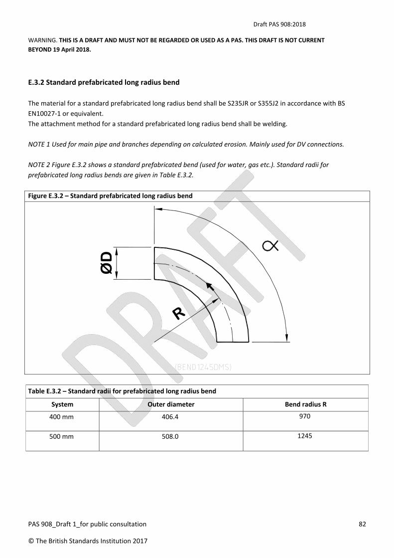
Draft PAS 908:2018
WARNING. THIS IS A DRAFT AND MUST NOT BE REGARDED OR USED AS A PAS. THIS DRAFT IS NOT CURRENT
BEYOND 19 April 2018.
PAS 908_Draft 1_for public consultation 82
© The British Standards Institution 2017
E.3.2 Standard prefabricated long radius bend
The material for a standard prefabricated long radius bend shall be S235JR or S355J2 in accordance with BS
EN10027‐1 or equivalent.
The attachment method for a standard prefabricated long radius bend shall be welding.
NOTE 1 Used for main pipe and branches depending on calculated erosion. Mainly used for DV connections.
NOTE 2 Figure E.3.2 shows a standard prefabricated bend (used for water, gas etc.). Standard radii for
prefabricated long radius bends are given in Table E.3.2.
Figure E.3.2 – Standard prefabricated long radius bend
Table E.3.2 – Standard radii for prefabricated long radius bend
System Outer diameter Bend radius R
400 mm 406.4 970
500 mm 508.0 1245
R
ØD

Draft PAS 908:2018
WARNING. THIS IS A DRAFT AND MUST NOT BE REGARDED OR USED AS A PAS. THIS DRAFT IS NOT CURRENT
BEYOND 19 April 2018.
PAS 908_Draft 1_for public consultation 83
© The British Standards Institution 2017
Annex F (informative)
Collection station footprints
Table F.1 and Table F2 provide for planning purposes typical, collection station footprints and truck loading areas
for varying numbers of waste fractions.
Actual Collection station areas might vary significantly from these dependant on project requirements and
whether different types of systems are included within one collection station
Configurations for typical filter/compactor‐type collection stations will be similar to these
Table F.1 Typical compactor type and collection station sizes
Minimum Compactor type, Collection station sizes
1‐fraction 2‐fraction 3‐fraction
Building footprint area 308 m2 374 m2 493 m2
Building foot print (LxWxH) 22 x 14 x 9 m 22 x 17 x 9 m 29 x 17 x 9 m
Container loading area 330 m2 330 m2 435 m2
Maximum waste 30 t/day 50 t/day 45 t/day
Table F.2 sets out typical filter type collection station footprint and truck loading area for varying number of waste
fractions.
Table F.2 – Typical filter type collection station sizes
Typical filter type collection station sizes
1 fraction 2 fractions 3 fractions
Building foot print area 198 m2 286 m2 374 m2
Building foot print (L/W/H) 22/9/4.5 m 22/13/4.5 m 22/17/4.5 m
Container loading area 135 m2 195 m2 255 m2
Maximum waste 4 t/day 7 t/day 10 t/day

Draft PAS 908:2018
WARNING. THIS IS A DRAFT AND MUST NOT BE REGARDED OR USED AS A PAS. THIS DRAFT IS NOT CURRENT
BEYOND 19 April 2018.
PAS 908_Draft 1_for public consultation 84
© The British Standards Institution 2017
Annex G (informative)
Sound Levels
Generally the location of PWCS equipment should follow the requirements of architectural codes which require
that they are not placed adjacent to sensitive areas such as occupied rooms.
1) Collection station
a. Noise levels in the collection station arise from 2 main areas
i. Exhauster room:
The sound level from the exhausters during operation are typically 100‐ 110Db In order to
attenuate this the exhauster room is required to be constructed of a 200mm thick
concrete or block wall with internal wall and ceiling insulation of 100mm thick faced with
perforated galvanized metal sheet.
ii. Collection hall housing the cyclone/separator/compactor:
The sound levels in the collection hall are typically 80 Db during operation, however as
the hall is quite large, no additional attenuation to reduce noise levels outside the hall are
required unless the hall is located adjacent to an area requiring specific acoustic
treatment.
Sound levels inside the hall would be subject to the HSE requirements for plant rooms.
b. Noise levels in the feeding and transport system – generally for suspended pipe and DV rooms
within buildings ‐ buried pipe systems do not require acoustic treatment:
i. DV rooms:
1. sound levels in DV rooms are generated from the operation of AV and DVs.
Typical sound levels are 80‐90 Db at 3 sec peak and are generated by the initial
opening of the AV and is usually included with a silencer to reduce sound levels.
2. if the DV/ AV room is placed in typically a two hour fire rated enclosure, then
sufficient attenuation is usually achieved.
3. additional acoustic treatment might be required for sensitive areas such as
theatres, hospitals etc.
ii. Transport pipe
The sound levels in for the transport pipe and the need for acoustic treatment are
dependent on the following
1. waste transport speed;
2. pipe thickness;
3. type of waste;
4. architectural finishes – e.g. acoustic properties of ceiling;
5. distance of the pipe from user affected by the sound level, e.g. in hospitals pipe
may be 2‐3 m above a ceiling in a corridor providing significant sound
attenuation;
6. typical background sound level of the area the pipe is located within; and

Draft PAS 908:2018
WARNING. THIS IS A DRAFT AND MUST NOT BE REGARDED OR USED AS A PAS. THIS DRAFT IS NOT CURRENT
BEYOND 19 April 2018.
PAS 908_Draft 1_for public consultation 85
© The British Standards Institution 2017
7. typical peak sound levels 1m away from the un‐insulated suspended pipe during
operation for a period of 5 seconds at any one location are 80‐85 Db in residential
developments whilst waste is transported at a speed of approximately 18‐20m/s.

Draft PAS 908:2018
WARNING. THIS IS A DRAFT AND MUST NOT BE REGARDED OR USED AS A PAS. THIS DRAFT IS NOT CURRENT
BEYOND 19 April 2018.
PAS 908_Draft 1_for public consultation 86
© The British Standards Institution 2017
Annex H (normative)
Electrical power requirements
H.1 Calculation of required power
The minimum requirements of the current needed for a standard SVS installation shall be calculated as follows.
a) Alternative 1 (A1): One exhauster starting + all but one exhauster running at no load; or
b) Alternative 2 (A2): All exhausters running at nominal load.
For both alternatives add:
1) B1: One rotating screen running;
2) B2: One compactor running;
3) B3: One compressor running; and
4) B4: Other electrical equipment running (e.g. control system, service power, air conditioning and light).
The total current is the sum of A1 or A2 (the highest is chosen) + B1 + B2 + B3 + B4. A 10 % margin shall be added
and then the next existing standard circuit breaker size chosen. For installations using frequency drives method,
A2 shall be used. Soft and star delta starters as per BS EN 62271‐106:2011 shall use A1.
NOTE 1 An example of a power calculation is given in Figure G.1.
NOTE 2 The power calculation is for motor start, which is critical for the correct protection type in the power
supply. The starting current is ignored for the small motors since the duration is short and the current is relatively
small compared to the total current. Also, the low power factor for these motors is ignored. The exhauster starting
current is three times the nominal current if soft starters or Y/D starters are used.
Frequency drives start up according to settings and do not normally exceed the nominal load current.
NOTE 3 Normally the exhausters are designed for running at 90 % of their nominal load.
Exhausters running at no load (main valve closed) consume about 40 % of their nominal load.
Figure H.1 – Power calculation example
In an installation with 5 x 110 kW exhausters, 3 x 15 kW compactors, 3 x 7.5 kW rotating screens, 1 x 15 kW
compressor, line to line voltage (U) of 0.4 kV the minimum main circuit breaker size will be:
One 110 kW exhauster running at 90 % of nominal load: Above it says nothing of the 90 %. Quite common is that
all run at full nominal current. Especially if soft or Y/D starters are used, which allow over current in a high degree.
IExhNominalLoad = 0.9*110/(3*0.4*0.9) = 159 [A].

Draft PAS 908:2018
WARNING. THIS IS A DRAFT AND MUST NOT BE REGARDED OR USED AS A PAS. THIS DRAFT IS NOT CURRENT
BEYOND 19 April 2018.
PAS 908_Draft 1_for public consultation 87
© The British Standards Institution 2017
One 110 kW exhauster running at no load (40 %):
IExhNoLoad = 0.4*110/(3*0.4*0.9) = 71 [A].
One 110 kW exhauster starting:
IExhStart = 3*110/(3*0.4*0.9) = 529 [A]
A1:
1*IExhStart + 4*IExhNoLoad = 813 [A]
A2:
5*IExhNominalLoad = 795 [A]
B1: Rotating screen, 7.5 kW, running:
IRS = 7.5/(3*0.4) = 10 [A]
B2: Compressor 15 kW running:
ICE = 15/(3*0.4) = 22 [A]
B3: Compactor 15 kW running:
ICP = 15/(3*0.4) = 22 [A]
B4: No extra power consumption.
Alt A1 above is chosen: 813 [A]
1 Rotating screen running: 10 [A]
1 Compactor running: 22 [A]
1 Compressor running: 22 [A]
Sum: 867 [A]
A 10% margin gives the total sum: 1.1 * 867 = 954 [A]
The next standard size (see below) of circuit breakers larger than 954 [A] is 1000 [A].
NOTE The European standard circuit breaker sizes are: 100, 160, 250, 400, 630, 800, 1000, and 1250.
Draft PAS 908:2018
WARNING. THIS IS A DRAFT AND MUST NOT BE REGARDED OR USED AS A PAS. THIS DRAFT IS NOT CURRENT
BEYOND 19 April 2018.
PAS 908_Draft 1_for public consultation 88
© The British Standards Institution 2017
H.2 Equipotential bonding
All equipment with exposed conductive parts in the collection station shall be bonded. The following installations
in the collection station shall be bonded to the main earth bar:
a) waste transport pipes;
b) cable ladders;
c) ventilation shafts;
d) PE conductor;
e) conductive structures within the terminal; and
f) sewer, water, gas, heating and drainage pipes.
The incoming waste pipe shall be isolated in the collection station.
The insulating flange shall be mounted outside the collection station since electrical safety requires all pipes
inside the station to be bonded.
NOTE 1 See BS EN 60204‐1, Clause 8 and HD 60364‐5‐54.
NOTE 2 There might be regional variations and attention is drawn to any local regulations.
NOTE 3 If the installation is made in an existing building, or a building where the equipotential bonding system is
not completely controlled, the use of equipotential bonding should be considered to secure electrical safety.
NOTE 4 This corrosion protection method is based on having the whole pipe system as an insulated unit with no
connections to earth. This requires usage of an insulating flange adjacent to the collection station as well as before
entering other buildings where regulation requires bonding of pipes inside the buildings.

Draft PAS 908:2018
WARNING. THIS IS A DRAFT AND MUST NOT BE REGARDED OR USED AS A PAS. THIS DRAFT IS NOT CURRENT
BEYOND 19 April 2018.
PAS 908_Draft 1_for public consultation 89
© The British Standards Institution 2017
Annex I (normative)
Product requirements
Table I.1 – Product requirements
Component Part Activity Purpose Requirement
Inlet door Receipt of waste via
inlet door (which could
also be a bin at ground
level or within the
public realm).
To safely receive
waste
Accessible to all
users.
Sized to receive only
acceptable wastes
which will not block
the system.
Conform to BS 1703 or NFPA 82.
Stainless steel – SS304.
Storage section To hold waste until it is
ready for discharge to
the pipe network.
Secure storage of
required waste
volumes.
Sealed to retain any
odours/leakage that
may occur from the
waste.
Storage pipe thickness to be:
a minimum of 2 mm in buildings
up to two storeys;
a minimum of 3 mm in buildings
above two storeys; and
a maximum of 8 mm (e.g. in high
rise buildings with a load of ≥ 500
kg/day).
Discharge valve
(DV)
To open and feed
recyclables/wastes
into the pipe network
at appropriate times.
To open and close
securely as the
system requires.
Dependent on DV type.
Air valve (AV) To provide the air
required to ensure fast
emptying of the
storage area.
To separate the
waste pillar by letting
in air between the
waste bags, without
any leakage or
splashing.
Can be used for all pipe dimensions, with a
variation in the nozzle size (which is
chosen based on maximum air speed and
necessary negative pressure below the
DV).

Draft PAS 908:2018
WARNING. THIS IS A DRAFT AND MUST NOT BE REGARDED OR USED AS A PAS. THIS DRAFT IS NOT CURRENT
BEYOND 19 April 2018.
PAS 908_Draft 1_for public consultation 90
© The British Standards Institution 2017
Sectioning valve
(SV)
Divide pipe network
into different sections.
Reduce pressure
losses due to leakage
from the discharge
valves (energy
consumption) and to
reduce failure
consequences.
—
Transport pipe To transport waste
from inlet to collection
station.
To contain and
transport waste
under air speeds of
18–24 metres per
second, in a
suspended or buried
pipe.
Mild steel material.
Diameter of DN400‐500 mm.
Thickness > 6 mm on straight sections.
Thickness > 9 mm on bends.
Pipe diverter
valve (PDV)
Used to divert
different fractions of
waste to relevant
container or same
fraction of waste to
more than one
container.
To divert and direct
waste to the required
storage container.
A customized protective enclosure shall be
provided around pipe diverter valves
(PDV), except for the enclosed type
(PDVE).
Cut‐off valves shall be installed after the
PDV to prevent inner leakage.
Separator The rotating screen at
the top of the
separator, separates
waste from the
transportation air.
To separate waste
from transportation
air.
To connect to the
container/compactor.
The connection chute from separator to
compactor is welded (airtight) in situ to
the separator flange and the connection
box.
A gap shall be left between the connection
box and the compactor. The gap must be
covered by gaffer tape, rubber sleeve and
hose clamps.
The connection is made telescopic to
simplify installation.
Compactor To compact and
compress waste for
storage and off‐site
collection.
To reduce waste in
volume by
compressing it, in
order to store more
in the available
container.
The compactor shall be airtight and
resistant for negative pressure. No air
leakage can be allowed.
The compactor shall have a higher
theoretical throughput measured in
m3/minute, than the amount of waste
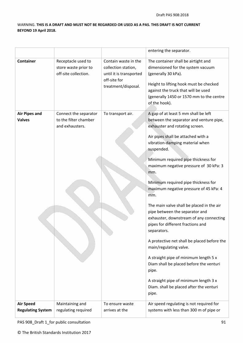
Draft PAS 908:2018
WARNING. THIS IS A DRAFT AND MUST NOT BE REGARDED OR USED AS A PAS. THIS DRAFT IS NOT CURRENT
BEYOND 19 April 2018.
PAS 908_Draft 1_for public consultation 91
© The British Standards Institution 2017
entering the separator.
Container Receptacle used to
store waste prior to
off‐site collection.
Contain waste in the
collection station,
until it is transported
off‐site for
treatment/disposal.
The container shall be airtight and
dimensioned for the system vacuum
(generally 30 kPa).
Height to lifting hook must be checked
against the truck that will be used
(generally 1450 or 1570 mm to the centre
of the hook).
Air Pipes and
Valves
Connect the separator
to the filter chamber
and exhausters.
To transport air. A gap of at least 5 mm shall be left
between the separator and venture pipe,
exhauster and rotating screen.
Air pipes shall be attached with a
vibration‐damping material when
suspended.
Minimum required pipe thickness for
maximum negative pressure of 30 kPa: 3
mm.
Minimum required pipe thickness for
maximum negative pressure of 45 kPa: 4
mm.
The main valve shall be placed in the air
pipe between the separator and
exhauster, downstream of any connecting
pipes for different fractions and
separators.
A protective net shall be placed before the
main/regulating valve.
A straight pipe of minimum length 5 x
Diam shall be placed before the venturi
pipe.
A straight pipe of minimum length 3 x
Diam. shall be placed after the venturi
pipe.
Air Speed
Regulating System
Maintaining and
regulating required
To ensure waste
arrives at the
Air speed regulating is not required for
systems with less than 300 m of pipe or
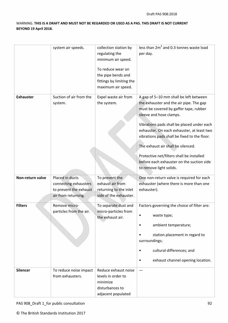
Draft PAS 908:2018
WARNING. THIS IS A DRAFT AND MUST NOT BE REGARDED OR USED AS A PAS. THIS DRAFT IS NOT CURRENT
BEYOND 19 April 2018.
PAS 908_Draft 1_for public consultation 92
© The British Standards Institution 2017
system air speeds. collection station by
regulating the
minimum air speed.
To reduce wear on
the pipe bends and
fittings by limiting the
maximum air speed.
less than 2m3 and 0.3 tonnes waste load
per day.
Exhauster Suction of air from the
system.
Expel waste air from
the system.
A gap of 5–10 mm shall be left between
the exhauster and the air pipe. The gap
must be covered by gaffer tape, rubber
sleeve and hose clamps.
Vibrations pads shall be placed under each
exhauster. On each exhauster, at least two
vibrations pads shall be fixed to the floor.
The exhaust air shall be silenced.
Protective net/filters shall be installed
before each exhauster on the suction side
to remove light solids.
Non‐return valve Placed in ducts
connecting exhausters
to prevent the exhaust
air from returning.
To prevent the
exhaust air from
returning to the inlet
side of the exhauster.
One non‐return valve is required for each
exhauster (where there is more than one
exhauster).
Filters Remove micro‐
particles from the air.
To separate dust and
micro‐particles from
the exhaust air.
Factors governing the choice of filter are:
• waste type;
• ambient temperature;
• station placement in regard to
surroundings;
• cultural differences; and
• exhaust channel opening location.
Silencer To reduce noise impact
from exhausters.
Reduce exhaust noise
levels in order to
minimize
disturbances to
adjacent populated
—

Draft PAS 908:2018
WARNING. THIS IS A DRAFT AND MUST NOT BE REGARDED OR USED AS A PAS. THIS DRAFT IS NOT CURRENT
BEYOND 19 April 2018.
PAS 908_Draft 1_for public consultation 93
© The British Standards Institution 2017
areas (if any).
Exhaust air
control
System to facilitate
release of exhaust air.
Exhaust channel (i.e.
pipe), with an angled
cone to facilitate the
exiting of exhaust air.
The exhaust air pipe shall be vertical.
Pipe diameter of the exhaust air pipe shall
be larger than the waste transport pipe to
reduce pressure drop and minimize over‐
pressure in the filter chamber.
Exhaust air pipe shall end with an angled
cone at the top with 7º side to increase
the exhaust air speed to approximately 20
m/s.
Exhaust air pipe shall end as high over the
terminal roof as possible, but not less than
3 m.
Compressed air
system
Produces air flow to
manoeuvre all the
valves.
Dried air enters the
compressed air
system which
increases air pressure
in order to activate
the system and
manoeuvre and open
valves as required.
The compressor shall be placed together
with tank, air‐dryer/cooler and drainage
equipment.
It is recommended to place the
compressor in the exhauster room. In this
case, measures shall be taken to control
the climate so the equipment is not
affected or damaged by poor climate
conditions.
The compressed air shall be dry enough
not to cause any magnetic valves to freeze
or corrode.
A floor drain shall be provided near to the
compressor equipment.
Power and control
system
The control system
starts, controls, and
monitors the
automated collection
process and the
equipment involved in
the process.
To run the system
efficiently and
effectively; to
highlight any
blockages or issues.
The control system includes the following
components:
• exhauster motor control centre;
• compactor or motor control
centre;
• air speed regulating system
controls; and

Draft PAS 908:2018
WARNING. THIS IS A DRAFT AND MUST NOT BE REGARDED OR USED AS A PAS. THIS DRAFT IS NOT CURRENT
BEYOND 19 April 2018.
PAS 908_Draft 1_for public consultation 94
© The British Standards Institution 2017
• electric supply controls.
The configuration of the control system is
governed by the required capacity of the
waste collection system.
Vacuum pumps An exhauster based on
pump technique.
To create negative
pressure in the
transport pipe
To create a difference between the
atmospheric pressure and the pressure in
the transport air stream.

Draft PAS 908:2018
WARNING. THIS IS A DRAFT AND MUST NOT BE REGARDED OR USED AS A PAS. THIS DRAFT IS NOT CURRENT
BEYOND 19 April 2018.
PAS 908_Draft 1_for public consultation 95
© The British Standards Institution 2017
Annex J (informative)
Commissioning Procedure Outline
The following denotes the commissioning procedure for a PWCS.
TABLE OF CONTENTS
Introduction
Definition & Abbreviations
Codes, Standard & References
o General References
Specifications
Scope
Control area plc waste handling room
Operator terminals
Control box at inlet
CMS visualization terminal
Responsibilities
Commissioning team
Environmental, Health & Safety Requirements
Project Safety Plan
Emergency procedures
Contractual Requirements
Information to Personnel
Permit Requirements
Protective and Safety Requirements
Plant and Equipment Requirements
Design criteria
System Plans
Installation Areas
o Basement
o Ground Floor
o First Floor
System Pre‐requisite and System Interfaces
o System Pre‐requisites
o System interfaces
Testing & Commissioning Procedure
o System Start‐up
Permanent Power Supply
PLC I/O Test
Emergency ‐Stop Test
Waste Handling System
Static Acceptance (Pre Functional Tests) ‐
o Waste Collection Station Equipment ‐
MCC1.0
Compactor /Container

Draft PAS 908:2018
WARNING. THIS IS A DRAFT AND MUST NOT BE REGARDED OR USED AS A PAS. THIS DRAFT IS NOT CURRENT
BEYOND 19 April 2018.
PAS 908_Draft 1_for public consultation 96
© The British Standards Institution 2017
Air cooling unit
Odour Neutralization System
Air pipes
Screw conveyor
Separator System
Main Valve
Evacuating Valve
Pipe Diverter Valve
Dust Filter
Vacuum Pump
o Feeding Equipment
DV 1
DV 2
Pipe System DN 500
Set‐Up Operation / Off‐line Tests (Operational)
o Waste Collection Station Equipment
ECC1.0
MCC1.0
Screw conveyor 2
Compactor Container
Odour Neutralization System
Air Cooling Unit 3
Backup mode
Alarm verification
ECC1.1
MCC1.1
Alarm verification
Acceptance Form Set‐Up Operation
Pre Acceptance Test (Functional Performance Test) ‐
o Throughput test
o Preliminary availability test
o Noise level test
o Acceptance Form Pre Acceptance Test
STAFF TRAINING
ONLINE TEST
o Throughput test
o Availability test
FINAL ACCEPTANCE
Attachments
Equipment Schedule
List of Test Tools & Equipment
Drawings
Vendor Information
Static Acceptance Check List ‐
Set Up Operation Acceptance Check Lists
Pre‐acceptance Test Check Lists ‐

Draft PAS 908:2018
WARNING. THIS IS A DRAFT AND MUST NOT BE REGARDED OR USED AS A PAS. THIS DRAFT IS NOT CURRENT
BEYOND 19 April 2018.
PAS 908_Draft 1_for public consultation 97
© The British Standards Institution 2017
Alarm List Test Sheet
Airspeed measurement instructions: per system
Airspeed measurement instructions:
Availability Calculation
Parameter settings
Punch List
Risk Assessment
The completion of the Commissioning procedure for the PWCS system should include the provision of an
O&M manual in accordance with BSRIA Guide BG1/2007 or as per Project specifications and requirements
which should include the following:
a) Collection of all ITP records for equipment supplied to the project;
b) Collection of all written warranties from 3rd party suppliers;
c) Provision of approved As‐ Built drawings; and
d) Collection of all commissioning tests , reports and data.

Draft PAS 908:2018
WARNING. THIS IS A DRAFT AND MUST NOT BE REGARDED OR USED AS A PAS. THIS DRAFT IS NOT CURRENT
BEYOND 19 April 2018.
PAS 908_Draft 1_for public consultation 98
© The British Standards Institution 2017
Annex K (informative)
Operation and maintenance
K.1 General
It is common for PWCS end users to require that the PWC system supplier enter into an operation and
maintenance (O&M) agreement or service level agreement (SLA) at the completion of the installation contract.
Although requirements for the level of service will be subject to the project and location, the following scope
relates to the PWCS equipment. The scope can be measured against key performance indicator (KPI) targets
which will be determined by the owners’ facilities managers.
As a minimum, the following are requirements to be included within the SLA:
Routine maintenance and servicing work should in general include checking and necessary adjustment, cleaning,
greasing, oiling, painting if required, supply and replacement of any parts or equipment.
The following list is a brief outline of preventive maintenance work required to be carried out by the contractor
and is by no means exhaustive. The contractor should base on his/her own engineering judgment and
recommendation of the PWCS manufacturer to include any other items of work which are essential to the proper
and efficient operation of the installation. Detailed maintenance proposal should be submitted to the
employer/facility manager for approval.
K.2 Daily and weekly maintenance service
Daily maintenance service including visual check of all rotating and translating (sliding) parts for any abnormal
vibration or noise, applying lubricants if necessary, cleaning fluid/debris/dust accumulation replenishing
oil/consumable items, replacing burnt fuses/luminaries, etc.
Weekly maintenance service include general cleaning, check for any damage detector or sensor location
adjustment, cleaning of detectors or sensors, etc. should be provided for, but not limited to the following
equipment –
1. Refuse storage and discharge facilities;
2. Adjustable frequency drive if any;
3. Velocity monitoring stations – ECC panels, frequency drive exhauster;
4. Air compressor;
5. Refuse separator and compactor;
6. Refuse conveyance duct diverter;
7. Deo‐filters and Dust filters;
8. Lighting in Central collection terminal; and
9. Discharge Valves (DVs)
K.3. Monthly Maintenance Services
Monthly maintenance services should be provided for, but not limited to, the following equipment:

Draft PAS 908:2018
WARNING. THIS IS A DRAFT AND MUST NOT BE REGARDED OR USED AS A PAS. THIS DRAFT IS NOT CURRENT
BEYOND 19 April 2018.
PAS 908_Draft 1_for public consultation 99
© The British Standards Institution 2017
a) refuse disposal inlets;
b) air inket valves/dampers;
c) reuse sorage and discharge facilities;
d) refuse separator and compactor;
e) refuse conveyance duct diverter;
f) refuse containers;
g) container conveyor;
h) dust filter facility;
i) deo‐filter and dust filters;
j) air blower;
k) compressed air supply facilities;
l) ventilation fans and duct works;
m) room air coolers orspit type air conditionrs;
n) electrical / motor control centers;
o) power distribution panels/cubicles;
p) discharge Valves (DVs); and
q) screw tank.
Monthly maintenance should include, where appropriate:
a) fixing and lightening of loose bolts and nuts, doors, electrical components and wiring;
b) lubricating and greasing rollers, pins, bearings hinges;
c) motor starters contact check and rectification;
d) belt check and rectification;
e) belt tension check and adjustment;
f) oil level check and replenishing;
g) detector or sensor location adjustment, cleaning of detectors sensors;
h) check for excessive wear of moving parts;
i) check for any damage, leakage, abnormal vibration or noise;
j) cleaning accumulated fluid, debris or dust;
k) general cleaning replacing filters; and
l) replenishing consumable items.
K.4. Quarterly Maintenance Service.
The following quarterly maintenance services should be provided for, but not limited to:

Draft PAS 908:2018
WARNING. THIS IS A DRAFT AND MUST NOT BE REGARDED OR USED AS A PAS. THIS DRAFT IS NOT CURRENT
BEYOND 19 April 2018.
PAS 908_Draft 1_for public consultation 100
© The British Standards Institution 2017
a) Air Inlet valves/dampers
1) Check that valve disc and sealing are in correct positions; and
2) Check linkage between valve disc and actuating cylinder/motor.
b) Discharge valves/dampers
1) Clean valve disc on both sides;
2) Check that valve disc sealing are in correct postions;
3) Cheack linkage between valve disc and actuating cylinder/motor; and
4) Check that valve is working properly.
c) Refuse sepatator.
1) Check and clean the interior of separator;
2) Check air lightness of all sealing;
3) Check all inspecton openings are air tight;
4) Check the condition and tension of driving belt, adjust or replace as necessary;
5) Clean the rotating screen;
6) Check the clearance between rotating screen and enclosure;
7) Grease bearing; and
8) Check and clean air inlet and outlet.
d) Refuse Compactor
1) Check that there is no oil leakage from hydraulic cylinders;
2) Check the condition of the lining; and
3) Check the air tightness of seal between compactor and container.
e) Refuse Container
1) Check the general condition of container;
2) Check sealing for the main/loading door(s); and
3) Check the door locking devices, hinges are in proper condition.
f) Dust Filtering Facility
1) Open the filter chamber and check the filter condition; and
2) Check that sealing for filter chamber and dust container are air tight.
g) Air Blower
1) Check the condition of coupling between motor and fan;
2) Clean the impeller and check for any cracks;
3) Check condition of anti‐vibration mountings; and
4) Check condition of inlet guide vanes and protection net.
h) Air Compressor Set.
1) Check the functions;
2) Check the preset pressure range;

Draft PAS 908:2018
WARNING. THIS IS A DRAFT AND MUST NOT BE REGARDED OR USED AS A PAS. THIS DRAFT IS NOT CURRENT
BEYOND 19 April 2018.
PAS 908_Draft 1_for public consultation 101
© The British Standards Institution 2017
3) Check and replace filter of air cooler if necessary; and
4) Check and replace air inlet filter of compressor if necessary.
i) Central Collection Station
1) Clean acoustic wall lining; and
2) Rinse the plant room floor.
j) Screw Tank stations
1) Check the spirel blade in good condition;
2) Check any crack in the spirel blade;
3) Check the bearing of the spirel;
4) Check condition of motor; and
5) Check over all condition of screw tank.
K.5 Runtime Maintenance Service.
Maintenance services based on the equipment runtime should be provided for, but not limited to, the equipment
listed. Maintenance intervals should be as recommended by the equipment manufacturers but not exceed the
figures indicated below.
a) Every 500 hours
1) Lubricate bearing of air blower; and
2) Replace air filter for air compressor.
b) Every 70 hours
Replace hydraulic oil filter cartridge of refuse compactor.
c) Every 1000 hours.
Change muffler element of air compressor.
d) Every 1500 hours
1) Clean hydraulic tank of refuse compactor;
2) Change hydraulic oil of refuse compactor; and
3) Lubricate motor of air blower.
e) Every 3000 hours
Change air compressor
f) Every 4000 hours
Clean and grease worm screw bearings of refuse compactor.
g) Every six (6) months
1) Replace bag type dust filters;
2) Replace activated carbon filters;

Draft PAS 908:2018
WARNING. THIS IS A DRAFT AND MUST NOT BE REGARDED OR USED AS A PAS. THIS DRAFT IS NOT CURRENT
BEYOND 19 April 2018.
PAS 908_Draft 1_for public consultation 102
© The British Standards Institution 2017
3) Clean discharge valve and lubricate/grease moving parts; and
4) Ensure refuse storage and discharge facilities are firmly in position and no air or fluid leakage.
h) Every (12) months
1) Change lubriccant of refuse compactor;
2) Perform functional test of all electrical protective devices;
3) Check insulation resistrance of all cables;
4) Ensure correct phase identification provided at ends of cables;
5) Check cables for mechanical damage and rectify as necessary;
6) Check condition of all power cable terminations and rectify as necessary; and
7) Clean the condenser, evaporator and fans of room air cooler or split type air conditioner.

Draft PAS 908:2018
WARNING. THIS IS A DRAFT AND MUST NOT BE REGARDED OR USED AS A PAS. THIS DRAFT IS NOT CURRENT
BEYOND 19 April 2018.
PAS 908_Draft 1_for public consultation 103
© The British Standards Institution 2017
Bibliography
Standards publications
For dated references, only the edition cited applies. For undated references, the latest edition of the referenced document (including any amendments) applies.
BS 1703, Refuse Chutes and Hoppers
BS 476 (all parts), Fire tests on building materials and structures
BS 5906, Waste Management in Buildings – Code of Practice
BS EN 13965‐1, Characterization of Waste ‐ Terminology ‐ Part 1: Material related terms and definitions
BS EN 14899, Characterization of waste – Sampling of waste materials – Framework for the preparation and
application of a sampling plan.
BS EN 418, Safety of machinery – Emergency stop equipment, functional aspects – Principles for design
BS EN 60204 (all parts), Safety of machinery – Electrical equipment of machines
BS EN 953, Safety of machinery – Guards – General requirements for the design and construction of fixed and
movable guards
BS EN 954‐1, Safety of machinery – Safety related parts of control systems – Part 1: General principles for design
BS ISO 3857‐4:2012, Compressors, pneumatic tools and machines – Vocabulary – Air treatment
Low‐voltage electrical installations – Selection and erection of electrical equipment – Earthing arrangements,
protective conductors and protective bonding conductors
NFPA 82, Standard on Incinerators and Waste and Linen Handling Systems and Equipment
HD 60364‐5‐54 (IEC 60364‐5‐54:2002)AS, Low‐voltage electrical installations – Selection and erection of electrical
equipment – Earthing arrangements, protective conductors and protective bonding conductors
Other publications
[1] HOORNWEG, D., BHADA‐TATA, P. AND KENNEDY, C. Environment: Waste production must peak this century.
In: Nature International Weekly Journal, 30 October 2013. Available from:
https://www.nature.com/news/environment‐waste‐production‐must‐peak‐this‐century‐1.14032 [viewed October
2017]
[2] INTERNATIONAL SOLID WASTE ASSOCIATION. Underground Solutions for Urban Waste Management: Status
and Perspectives. Vienna: ISWA, 2013. Available from:
https://www.iswa.org/index.php?eID=tx_iswaknowledgebase_download&documentUid=3157 [viewed October
2017]

Draft PAS 908:2018
WARNING. THIS IS A DRAFT AND MUST NOT BE REGARDED OR USED AS A PAS. THIS DRAFT IS NOT CURRENT
BEYOND 19 April 2018.
PAS 908_Draft 1_for public consultation 104
© The British Standards Institution 2017
[3] HONKIO, K. The future of waste collection? Underground automated waste conveying systems. Waste
Management World, 2009. Available from: https://waste‐management‐world.com/a/the‐future‐of‐waste‐
collection‐underground‐automated‐waste‐conveying‐systems [viewed October 2017]
[4] Solid Waste Technology and Management.
[5] EUROPEAN PARLIAMENT. Directive 98/37/EC of the European Parliament and of the Council of 22 June 1998
on the approximation of the laws of the Member States relating to machinery Machinery. Luxembourg:
Publications Office of the European Union, 2016.
[6] EUROPEAN PARLIAMENT. Directive 2014/35/EU of the European Parliament and of the Council of 26 February
2014 on the harmonisation of the laws of the Member States relating to the making available on the market of
electrical equipment designed for use within certain voltage limits. Luxembourg: Publications Office of the
European Union, 2014.
[7] EUROPEAN COUNCIL. Council Directive 73/23/EEC of 19 February 1973 on the harmonisation of the laws of
Member States relating to electrical equipment designed for use within certain voltage limits (Low‐voltage
Directive).
[8] EUROPEAN COUNCIL. Council Directive 93/68/EEC of 22 July 1993 amending Directives 87/404/EEC (simple
pressure vessels), 88/378/EEC (safety of toys), 89/106/EEC (construction products), 89/336/EEC (electromagnetic
compatibility), 89/392/EEC (machinery), 89/686/EEC (personal protective equipment), 90/384/EEC (non‐
automatic weighing instruments), 90/385/EEC (active implantable medicinal devices), 90/396/EEC (appliances
burning gaseous fuels), 91/263/EEC (telecommunications terminal equipment), 92/42/EEC (new hot‐water boilers
fired with liquid or gaseous fuels) and 73/23/EEC (electrical equipment designed for use within certain voltage
limits).
[9] EUROPEAN COUNCIL. EU‐directive 89/336/EEC
[10] EUROPEAN COUNCIL. Council Directive 92/31/EEC of 28 April 1992 amending Directive 89/336/EEC on the
approximation of the laws of the Member States relating to electromagnetic compatibility.
Further reading
BS EN 16486, Machines for compacting waste materials or recyclable fractions ‐ Compactors ‐ Safety requirements
BS EN 476, General requirements for components used in drains and sewers
BS EN ISO 12100, Safety of machinery ‐‐ General principles for design ‐‐ Risk assessment and risk reduction
BS EN 16486, Machines for compacting waste materials or recyclable fractions – compactors – safety
requirements
BS EN 12574‐3:2017, Stationary waste containers Part 3: safety & health requirements
BS EN 805, Water supply – Requirements for systems and components outside buildings

Draft PAS 908:2018
WARNING. THIS IS A DRAFT AND MUST NOT BE REGARDED OR USED AS A PAS. THIS DRAFT IS NOT CURRENT
BEYOND 19 April 2018.
PAS 908_Draft 1_for public consultation 105
© The British Standards Institution 2017
BS EN 13071‐1, Stationary waste containers up to 5,000l, top lifted and bottom emptied – Part 1: General
requirements
BS EN 6683, Guide to installation and use of valves
ISO/DIS 18623‐1, DRAFT Air compressors and compressed air systems ‐ air compressors Part 1: safety
requirements
LAGERKVIST, A., ECKE, H. AND CHRISTENSEN, T. H. “Waste Characterization: Approaches and Methods”, in Solid
Waste Technology & Management, Volume 1 & 2 (ed T. H. Christensen). Blackwell Publishing Ltd, 2010.
RANHAGEN, U. AND GROTH, K. The SymbioCity Approach – A conceptual framework for sustainable urban
development. Stockholm: SKL International, 2012.