specification no. ti/spc/psi/trnpwr/6200
TRANSCRIPT
Spec No. TI/SPC/PSI/TRNPWR/6200 Effective from: …………………. Page 1 of 66
करषण ससथापन ननदशाऱय
TRACTION INSTALLATION DIRECTORATE
भारत सरकार, रऱ मतराऱय
GOVERNMENT OF INDIA
MINISTRY OF RAILWAYS
TECHNICAL SPECIFICATION FOR
60/84/100MVA, ONAN/ONAN/ONAF, 220kV/2X27kV or
132/2X27kV or 110/2X27kV or 66/2X27kV
Scott Connected Traction Power Transformer
Specification No. TI/SPC/PSI/TRNPWR/6200
ISSUED BY
_____________________________________________________________ TRACTION INSTALLATION DIRECTORATE
RESEARCH DESIGNS AND STANDARDS ORGANISATION
(MINISTRY OF RAILWAYS) MANAK NAGAR, LUCKNOW-226 011
_______________________________________________________
PREPARED BY CHECKED BY APPROVED BY
SIGNATURES
DATE
DESIGNATION
Spec No. TI/SPC/PSI/TRNPWR/6200 Effective from: …………………. Page 2 of 66
INDEX
Clause No. Description Page No.
1.0 Scope
2.0 Environmental & Operating Conditions
3.0 Design and constructional Features
3.1 Overall Dimensions
3.2 Transformer Tank
3.3 Marshaling Box and RTCC Panel
3.4 Core
3.5 Winding
3.6 Insulating Oil
3.7 Bushings and Terminal Connectors
3.8 Bushing Type current transformers
3.9 Clearances
3.10 Tap Changer
3.11 Cooling Equipment
3.12 Fasteners
3.13 Painting
4.0 List of related specifications
5.0 Rating, name plate and other information
6.0 Testing of Transformer
6.1 General
6.2 Tests during manufacture
6.3 Type tests
6.4 Routine tests
7.0 Maintenance manual, tool gauges etc.
8.0 Training of Indian Railways personnel
9.0 Packing, delivery and commissioning
10.0 Warranty
11.0 Spares & Sales-service and AMC
12.0 Technical Data and Drawings
13.0 Clause wise conformity, deviations etc.
14.0 Capitalisation of transformer losses
Annexure-1 Technical Specifications for Nitrogen Injection Fire Prevention and Extinguishing System for Oil Filled Transformer
Annexure-2 Technical Specifications for Fiber Optic Sensor
Annexure-3 Schedule of Guaranteed Performance, Technical and Other Particulars
Annexure-4 Formula for Calculation of Short Circuit Mechanical Forces
Annexure-5 Capitalization of Transformer Losses
Annexure-6 Principle of AT feeding system
Annexure-7 General Scheme for Traction Power Supply System

Spec No. TI/SPC/PSI/TRNPWR/6200 Effective from: …………………. Page 3 of 66
1.0 Scope:
1.1 This specification applies to the 60/84/100MVA, ONAN/ONAN/ONAF, 220kV/2X27kV or 132/2X27kV or 110/2X27kV or 66/2X27kV Scott Connected traction Power Transformer for Autotransformer (AT) feeding system for installation in Indian Railway's Traction Sub-Stations, which may be manned or unattended type.
1.2 RDSO’s ISO procedure: “All the provisions contained in RDSO’s ISO procedures laid down in Document No. - QO-D-8.1-11 dated 12.09.2018 (titled “Vendor-changes in approval status”) and subsequent versions/amendments thereof, shall be binding and applicable on the successful vendor/vendors in the contracts floated by Railways to maintain quality of products supplied to Railways.”
1.3 Traction Power supply system (2X25kV AT Feeding System)
1.3.1 General scheme 1.3.1.1 The electric power for traction is supplied in ac 50 Hz, single phase through 2 x 25 kV AT
feeding system, which has a feeding voltage (2x25kV) from the Traction Sub-Station (TSS) two times as high as catenary voltage (25 kV) with respect to earth/rail . The power is fed from the TSS through, catenary wire and feeder wire is steeped down to the catenary voltage by use of autotransformers (ATs) installed about every 13 to 17 km along the track, and then fed to the locomotives. In other words, both the catenary voltage and feeder voltage are 25 kV with respect to earth/rail, although the sub-station feeding voltage between catenary and feeder wires is 50 kV. Therefore, the catenary voltage is the same as that of the conventional 25 kV system.
1.3.1.2 Since the power is supplied in two times higher voltage (50kV), the 2 x 25 kV At feeding system is suitable for a large power supply, and it has the following advantages, compared with conventional feeding systems: (a) Less voltage drop in feeder circuit. (b) Large spacing between traction sub-stations. (c) Less interference to adjacent telecommunication lines, if any.
1.3.1.3 The power is obtained from 220 or 132kV or 110kV or 100kV or 66kV, three phase effectively earthed transmission network of the State Electricity Board, through Scott-connected/single phase transformers installed at the Traction Sub-Stations. The primary windings of the single phase transformer is connected to two phases of the transmission network. Where Scott Connected transformers are used, the primary windings are connected to the three phases of the transmission network. The single-phase transformers at TSS are connected to the same two phases of the transmission network (referred as single phase connection), or alternatively to different pairs of phases to three single phase transformers forming a delta connection on the primary side. Out of three single phase transformers, one transformer feeds the OHE on either side of the TSS, and third remains as stand by. Thus two single phase transformers which feed the OHE constitute an open-delta connection (alternatively, referred as V-connection) on the three phase transmission network. The Scott-connected transformer and V-connected single phase transformers are effective in reducing voltage imbalance caused by the traction loads on the transmission network of the Electricity Board. The spacing between adjacent sub-station is normally between 70 to 100 km.
1.3.1.4 One outer side terminal of the secondary windings of traction transformer is connected to the catenary, the other outer side terminal being connected to the feeder. Two inner side terminals are, via series capacitors or directly, connected to each other, and their joint is solidly earthed and connected to the Traction Rails.

Spec No. TI/SPC/PSI/TRNPWR/6200 Effective from: …………………. Page 4 of 66
1.3.1.5 Generally, the load current (current drawn by electric locomotives) from the sub-station flows through the catenary and returns to the sub-station through the feeder. For a train in an AT-cell (distance between two consecutive ATs), most of the current is fed to the electric locomotive by the ATs of that AT-cell; the current returns in the rails/earth and is boosted up to the feeder through the neutral terminals of the autotransformers.
1.3.1.6 Approximately midway between two adjacent TSSs, a sectioning and paralleling post (SP) is provided. In order to prevent wrong phase coupling of power supply, a dead zone known as neutral section is provided in the OHE opposite the TSS as well as SP. At, the TSS, there are two feeder circuit breakers for either side of the TSS for controlling the power fed to the OHE, in a double track section. Out of the two feeder Circuit Breakers for one side, one feeds the OHE of that side while the other remains (open) as stand by. There is also a paralleling interrupter, which is normally closed, for either side of the TSS for paralleling the OHE of UP and DOWN tracks. For maintenance work and keeping the voltage drop within limits one or more sub-sectioning and paralleling posts (SSPs) are provided between TSS and SP. In a double track section, an SSP has four sectioning interrupters and one paralleling interrupter whereas an SP has two bridging circuit breakers (which remain open under normal feeding condition) and two paralleling interrupters. In case of fault in the OHE, the corresponding feeder circuit breaker of the TSS trips to isolates it.
1.3.1.7 A figure showing the principle of AT feeding system and a typical power supply diagram and Sectioning of the OHE are at the Appendix-1
1.3.2 PROTECTION SYSTEM
1.3.2.1 The Protection system of the Traction Transformer comprise the following: a. Differential protection. b. IDMT over current protection on HV & LV sides. c. Instantaneous over-current protection on Primary side. d. Earth fault protection on HV & LV sides. e. Protection against phase-failure on the secondary side. (i.e. to detect a malfunction
of a feeder/transformer circuit breaker ) f. Auxiliary relays for transformer faults i.e. Buchholz, excessive winding and oil
temperature trip and alarm, pressure relief device trip and alarm and low-oil level etc.
1.3.2.2 The protection system for the OHE comprises the following:
a. Distance protection b. Delta-I type fault selective protection. c. Instantaneous Overcurrent protection. d. Under voltage protection to avoid wrong phase coupling.
1.3.3 OHE General Data 1.3.3.1 The OHE consists of
a. A grooved copper conductor wire of 107mm2 section suspended directly from a stranded cadmium copper catenary of 65 mm2 section by a number of vertical dropper wires, usually at regular intervals (the contact wire and catenary wire together being referred as ‘catenary’ or ‘catenary wire’.
b. A feeder wire of standard all Aluminium Conductor (size 19/3.99mm) of 240 mm2 section.
1.3.4 Traction Power Transformer – General Data 1.3.4.1 The Traction Power Transformer is either single phase or Scott-Connected.
1.3.5 Nature of Traction Load on the OHE System

Spec No. TI/SPC/PSI/TRNPWR/6200 Effective from: …………………. Page 5 of 66
1.3.5.1 Traction load is of frequently and rapidly varying nature and may fluctuate between no load and over loads. The TSS equipment is subject to earth faults/short circuits caused by failure of insulation, snapping of OHE touching the earth, wire dropped by bird connecting the OHE to earth/overline structure and miscreant activity. On an average number of faults/short circuits per month is about 40, but in exceptional cases the number could be high as 120. The magnitude of the fault current may vary between 40% and 100% of the dead short circuit value. These faults are cleared by the feeder circuit breaker on operation of the distance, delta-I and instantaneous over current relays associated with the concerned feeder circuit breaker.
1.3.5.2 The AC electric locomotives are fitted, for conversion of AC to DC, with Single Phase Bridge connected silicon rectifiers with smoothing reactor for feeding the DC Traction motors. The rectifiers introduce harmonic currents in the 25kV power Supply system. On few of the electrified sections, locomotives fitted with phase controlled asymmetrical thyristor bridge, in place of silicon rectifiers are also in use; these introduce further harmonics in the system. The Typical percentage of harmonic present in the Traction Current with the Electric Locomotives are as follows:
Harmonics With Diode Rectifier With Thyristor
3rd (150Hz) 15% 32%
5th (250Hz) 6% 18%
7th (350Hz) 4% 8%
9th (450Hz) - 4%
11th (550Hz) - 5%
1.3.5.3 The average power factor of electric locomotives and electric multiple units generally varies between 0.7 and 0.8 lagging, without reactive power compensation.
1.3.5.4 Auxiliary Power at Traction Substation (TSS) 1.5.4.1 The following auxiliary power supplies are available at a traction substation.
a. 110 V DC from a battery (+15% & - 30%). b. 240V AC, Single Phase form Auxiliary Transformer.
1.5.4.2 Alarm/Trip devices, relays and motor for the tap changer on the traction power transformer shall operate by 110V DC.
1.5 Scope of supply, including accessories: The transformer shall be supplied complete with all parts, fittings and accessories necessary for its efficient operation. All such parts, fittings and accessories shall be deemed to be within the scope of this specification, whether or not specifically mentioned herein.
1.5.1 Conservator tank: It shall be of adequate capacity and complete with supporting bracket or structure, oil filling cap and drain valve of size 25 mm. The cylindrical portion of the conservator tank shall be of single piece construction without any gasketed joint. Suitable air cell/separator arrangement of high quality material shall be provided in the conservator to ensure that the transformer insulating oil does not come in contact with air. The material of cell/separator shall be coated fabric consisting of – highly resistant polyamide fabric, externally coated with transformer oil resisting coating (chemical), inner coating resisting ozone and weathering. Suitable instructions may please be provided for installation / commissioning and future maintenance of the air cell/separator arrangement.
1.5.2 Oil level gauge: It shall be of magnetic type having a dial diameter of 250mm. The gauge shall have markings corresponding to minimum oil level, maximum oil level and oil level corresponding to oil temperature of 300C, 450C and 850C. The oil level indicator shall be so designed and mounting that the oil level is clearly visible to an operator standing on the ground.
Spec No. TI/SPC/PSI/TRNPWR/6200 Effective from: …………………. Page 6 of 66
1.5.3 Silica gel breather: It shall be complete with oil seal and connecting pipes. The connecting pipes shall be secured properly. The container of the silica gel breather shall be of transparent flexi glass or similar material suitable for outdoor application. Orange Silica Gel (round balls 2 to 5mm) with quantity of two DTO-8 silica gel connecting with flanged mounting two pipes control through two different valves as per DIN:42567 & IS:3401 to be provided.
1.5.4 Pressure relief device: It shall be designed to operate to release internal pressure at preset value without endangering the equipment or operator and shall be of instantaneous reset type. Shroud Pressure relief Device will be used and have provision of discharge of oil from PRD to safe place by closed pipeline. This avoids hazards of fire and it is safe to persons working near Transformer & it is environmental friendly.
1.5.5 Filter valves: The bottom and upper filter valves shall be of 50mm size and suitably baffled to reduce aereation of oil. The valves shall be flanged to seat 40 mm adopter threaded to thread size P 1 - 1/2 for connection to oil filtration plant.
1.5.6 Drain valve: It shall be of size 80 mm fitted with an oil sampling device of size 15 mm.
1.5.7 Equipment Earthing terminals: Two earthing terminals shall be provided on the tank for its earthing with the help of 3 mild steel flats, each of size 75 mm x 8 mm. The terminals shall be clearly marked for earthing.
1.5.8 Buchholz relay: It shall be of double float type, with two shut - off valves of 80 mm size, one between the conservator tank and Buchholz relay and the other between the transformer tank and Buchholz relay. The relay shall have one alarm contact and one trip contact, none of the contacts being earthed. The contacts shall be magnetic switch or micro switch type, electrically independent and wired up to the marshaling box. A testing petcock shall be brought down through a pipe for the purpose of sampling the gas, if any, collected in the Buchholz relay.
1.5.9 Oil temperature indicator (OTI): It shall have one alarm contact, one trip contact and two normally open spare contacts, none of the contacts being earthed. The contacts shall be electrically independent. The OTI shall have a local /remote indication (in control panel) for oil temperature.
1.5.10 Winding temperature indicator (WTI): Two WTIs shall be provided, one for M Phase and the other for T-Phase. Each WTI shall have one alarm contact, one trip contact, two contacts for FAN operations and two normally open spare contacts, none of the contacts being earthed. The contacts shall be electrically independent. The WTI shall have a local /remote indication (in control panel) for winding temperature.
1.5.11 Thermometer pockets: A separate thermometer pocket with cap shall be provided on the bell tank for measuring the top oil temperature in the tank.
1.5.12 Thermo Siphon Filter: Thermo Siphon Filter System is to be provided for absorbing the moisture present in the insulating oil with the natural convection. The full details for installation and subsequent maintenance have to be furnished to RDSO and the consignee.
1.5.13 Nitrogen injection fire prevention and extinguishing system: The complete arrangement of Nitrogen injection fire prevention and extinguishing system has to be provided with the transformer. The specification and other requirements of this system have to be as per details given in the Annexure-1.
1.5.14 Fibre Optic Winding Hot Spot Temperature Monitor: Fibre optical winding hot spot temperature monitor to be provided with the transformer windings, connected in addition to the winding temperature indicator in parallel to measure transformer winding

Spec No. TI/SPC/PSI/TRNPWR/6200 Effective from: …………………. Page 7 of 66
hot spots in real time and activate control of the cooling system. The Fibre to be given high strength casing through jacketing and Fibre Optic shall be governed by IEC-60076-2 (Ed.3.0). The specification and other requirements of this system have to be as per details given in the Annexure-2.
1.5.15 All valves shall be of the double flange type and fitted with suitable blanking plates on the outer face of the exposed flange.
1.5.16 The capillary tubes for temperature indicators shall be able to withstand normal bending. They shall be supported properly without sharp or repeated bends or twists.
1.5.17 (i) The manufacturers of Part, Fittings and Accessories for the Transformer shall be mentioned in the SOGP, BOM & QAP and got approved. During prototype test, the accessories will be tested & performance monitored either at Customer Hold Point (CHP) or by Test Certificate (TC) verification as categorised below:
SN Name of the accessory Category
1. Motorised off Circuit tap changer CHP
2. Fire Extinguishing System CHP
3. Bucholz relay TC Verification
4. Pressure Relief Device TC Verification
5. Magnetic Oil level Gauge TC Verification
6. Bushing Current Transformer TC Verification
7. Silica gel Breather TC Verification
8. Wheel Valve, Double Flanged valve TC Verification
9. Analogue Type Temperature Indicators TC Verification
10. Terminal Connectors TC Verification
11. Radiators TC Verification
12. Fire Optic Winding Hot Spot Temperature Monitor TC Verification
(ii) Henceforth, while ordering Traction Power Transformer, a copy RDSO approved SOGP should be called for by the users. This document shall form basis for ordering accessories in the future.
(iii) In case manufacturers desire to change a particular make of accessory, prior approval of RDSO would be required on SOGP, Bill of Material (BOM) and Quality Assurance Plan (QAP).
(iv) In case of change of make of accessory under Customer Hold point (CHP) for regular production, the RDSO’s approval would be required separately on SOGP, BOM and QAP. The Traction Power Transformer manufacturer shall be responsible for availability of compatible accessories for the equipment approved.
(v) In case of Transformer manufacturer change in the make of OCTC for approved design of transformer, the routine testing of the transformer also shall be witnessed by RDSO.
2.0 Environmental & Operating Conditions
2.1 The transformer shall be suitable for outdoor use in dry arid and also tropical climates and in areas having heavy rainfall, pollution due to industry and coastal environment and severe lightning. The limiting weather conditions, which the equipment has to withstand in service, are indicated below:
S. No. Parameters Value
1. Maximum ambient air temperature 50 0 C
2. Minimum ambient air temperature - 2 0 C
4. Maximum relative humidity 100%
5. Annual rainfall Ranging between 1750 mm & 6250
Spec No. TI/SPC/PSI/TRNPWR/6200 Effective from: …………………. Page 8 of 66
mm
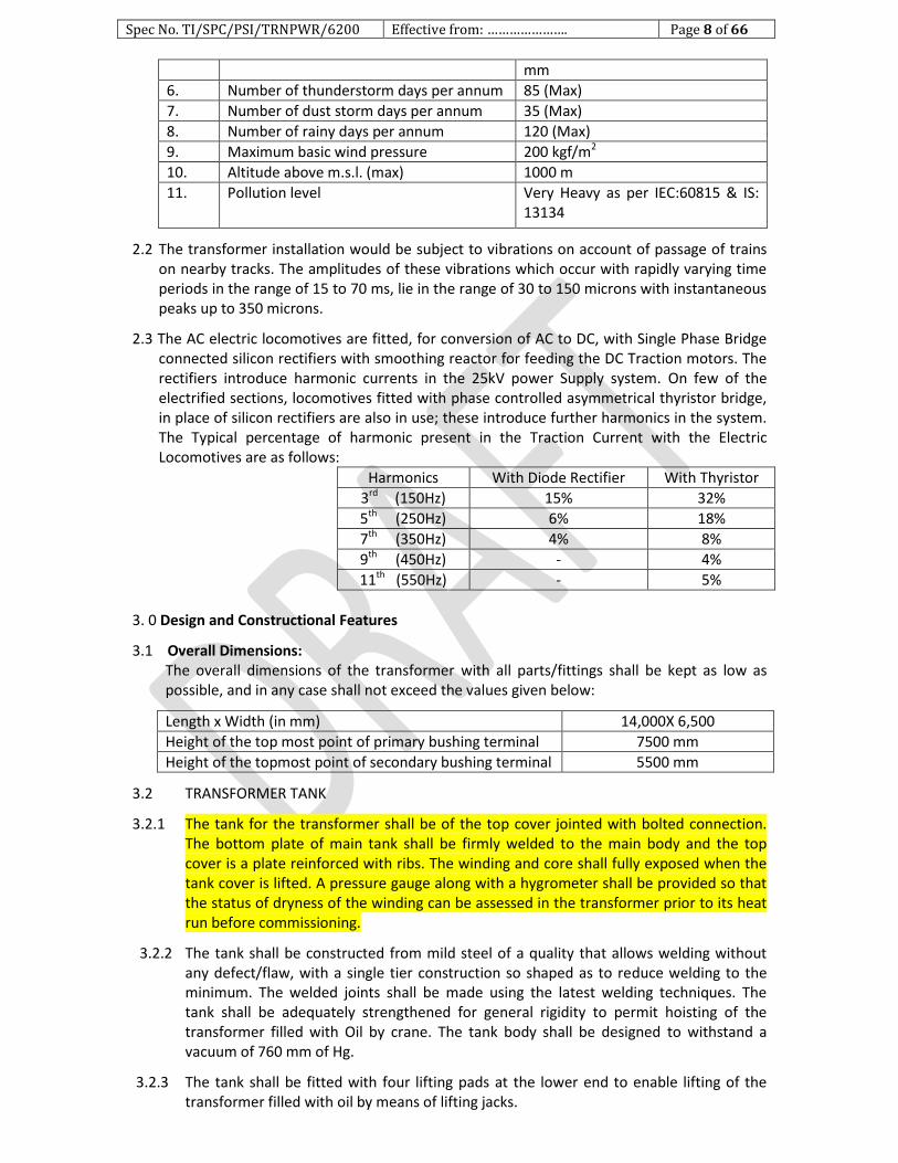
6. Number of thunderstorm days per annum 85 (Max)
7. Number of dust storm days per annum 35 (Max)
8. Number of rainy days per annum 120 (Max)
9. Maximum basic wind pressure 200 kgf/m2
10. Altitude above m.s.l. (max) 1000 m
11. Pollution level Very Heavy as per IEC:60815 & IS: 13134
2.2 The transformer installation would be subject to vibrations on account of passage of trains on nearby tracks. The amplitudes of these vibrations which occur with rapidly varying time periods in the range of 15 to 70 ms, lie in the range of 30 to 150 microns with instantaneous peaks up to 350 microns.
2.3 The AC electric locomotives are fitted, for conversion of AC to DC, with Single Phase Bridge connected silicon rectifiers with smoothing reactor for feeding the DC Traction motors. The rectifiers introduce harmonic currents in the 25kV power Supply system. On few of the electrified sections, locomotives fitted with phase controlled asymmetrical thyristor bridge, in place of silicon rectifiers are also in use; these introduce further harmonics in the system. The Typical percentage of harmonic present in the Traction Current with the Electric Locomotives are as follows:
Harmonics With Diode Rectifier With Thyristor
3rd (150Hz) 15% 32%
5th (250Hz) 6% 18%
7th (350Hz) 4% 8%
9th (450Hz) - 4%
11th (550Hz) - 5%
3. 0 Design and Constructional Features
3.1 Overall Dimensions: The overall dimensions of the transformer with all parts/fittings shall be kept as low as possible, and in any case shall not exceed the values given below:
Length x Width (in mm) 14,000X 6,500
Height of the top most point of primary bushing terminal 7500 mm
Height of the topmost point of secondary bushing terminal 5500 mm
3.2 TRANSFORMER TANK
3.2.1 The tank for the transformer shall be of the top cover jointed with bolted connection. The bottom plate of main tank shall be firmly welded to the main body and the top cover is a plate reinforced with ribs. The winding and core shall fully exposed when the tank cover is lifted. A pressure gauge along with a hygrometer shall be provided so that the status of dryness of the winding can be assessed in the transformer prior to its heat run before commissioning.
3.2.2 The tank shall be constructed from mild steel of a quality that allows welding without any defect/flaw, with a single tier construction so shaped as to reduce welding to the minimum. The welded joints shall be made using the latest welding techniques. The tank shall be adequately strengthened for general rigidity to permit hoisting of the transformer filled with Oil by crane. The tank body shall be designed to withstand a vacuum of 760 mm of Hg.
3.2.3 The tank shall be fitted with four lifting pads at the lower end to enable lifting of the transformer filled with oil by means of lifting jacks.

Spec No. TI/SPC/PSI/TRNPWR/6200 Effective from: …………………. Page 9 of 66
3.2.4 The tank shall be fitted with an under carriage and mounted on eight bi-directional swiveling type flanged rollers for being rolled on 1676 mm (5' 6") gauge track on which it shall also rest in the final position. The rollers shall be provided with detachable type locking arrangement to enable their locking after installing the transformer in the final position to prevent any accidental movement of the transformer.
3.2.5 There shall be at least five inspection covers of suitable size on the tank to enable inspection of the lower portions of bushings and the leads as well as various connections of the motorised off - circuit tap – changer/ on-load tap changer.
3.2.6 The rubberised cork/gaskets used in the transformer shall conform to IS: 4253 (Part - II).
3.2.7 All valves used in the transformer shall conform to IS: 3639 and shall be of good quality and leak proof. The manufacturer shall ensure that suitable anti - theft measures are provided on these valves so as to prevent theft of oil during transit/service.
3.2.8 Suitable supports shall be provided on the tank for fixing of Aluminum ladder for ease of maintenance at site. A suitable ladder of Aluminium shall be provided on the tank for ease of maintenance. Removable aluminum ladder shall be a part of transformer supply.
3.3 MARSHALLING BOX & RTCC PANEL
3.3.1 MARSHALLING BOX
3.3.1.1 A Vermin proof, weather proof and well ventilated marshalling box made of steel sheet of thickness not less than 2 mm, strengthened with adequate stiffeners, shall be provided on the left hand side of the transformer tank as viewed from the secondary terminals side. It shall have a hinged door with provision for pad locking. The door opening outward horizontally.
3.3.1.2 The marshalling box shall have a sloping roof. The top of the marshalling box shall be at a height of about 2 m from the rail level.
3.3.1.3 The marshalling box shall house the winding and oil temperature indicators, Contactors & MCB of cooling fan and terminal board. To prevent condensation of moisture in the marshalling box metal clad space heater, controlled by an associated thermostat and switch, shall also be provided. Cable glands shall be provided for the incoming and outgoing cables.
3.3.1.4 The temperature indicators shall be so mounted that their dials are at a height of not more than 1.6 m from the rail level. Transparent windows of tough acrylic plastic or similar non - fragile transparent material shall be provided on the marshalling box so as to enable reading of the temperature indicators without opening the door of the marshalling box.
3.3.1.5 All cables from the Cooling fans, Bushing Current Transformers, Buchholz Relay, Magnetic Oil Level Gauge, Pressure Relief Device and temperature indicators shall be run through suitable conduits/perforated covered cable trays up to the marshalling box. The cables shall be of 1100 V grade, PVC insulated, PVC sheathed, steel wire armoured, stranded copper conductor conforming to IS: 1554 (Part - I) or XLPE insulated, XLPE sheathed, steel wire armored, stranded copper conductor confirming to IEC:60502-1. The cables shall be adequately insulated for heat from the tank surface and the sun.
3.3.1.6 All wiring in the marshalling box shall be clearly identified by lettered / figured ferrules of the interlock type, preferably of yellow colour with black letters /figures. The AC and DC circuits shall be clearly distinguished and well separated from each other.

Spec No. TI/SPC/PSI/TRNPWR/6200 Effective from: …………………. Page 10 of 66
3.3.1.7 Suitable legend and schematic diagram plates made of stainless steel or anodized Aluminium with black lettering and lines shall be fixed on the inside surface of the marshaling box door.
3.3.2 Remote Tap Changer Control (RTCC) Panel
3.3.2.1 A Vermin proof, weather proof and well ventilated RTCC Panel made of steel sheet of thickness not less than 2 mm, strengthened with adequate stiffeners, shall be provided for providing in the control room of the substation.
3.3.2.2 The RTCC panel shall house actuating switch for electrical raise/lower control of tap changer, tap position indicator, signal lamps for “Tap changer in progress”, and all other auxiliary devices for remote electrical control of the OCTC.
3.3.2.3 RTCC panel shall also house the Digital Display of OTI & WTI and indications/control & pump of Fans (ONAF /OFAF mode) as mentioned in Para 3.12.
3.4 CORE
3.4.1 The core shall be built from high permeability Cold Rolled Grain Oriented (CRGO) silicon steel laminations conforming to IS: 3024. The flux density in any part of the core and yokes at the principal tapping with primary winding excited at the rated primary voltage and frequency shall not exceed 1.7T. The manufacturer shall furnish calculations to prove that this value shall not be exceeded. The core has to be preferably of boltless design to avoid the possibility of local heating.
3.4.2 The laminations for the core shall be free from waves, deformations and signs of rust. Both sides of the laminations shall be coated with suitable insulation capable of withstanding stress relief annealing. In assembling the core, air gaps shall be avoided. Necessary cooling ducts shall be provided in the core and yoke for heat dissipation. The core-clamping frame shall be provided with the lifting eyes for the purpose of tanking and untanking the core and winding of the transformer.
3.4.3 The core shall be electrically connected to the tank.
3.4.4 Yoke/core clamping bolts shall have adequate threaded length beyond the face of the nuts for tightening at a later stage, if need arises. Each of the core clamping bolts and the core-clamping framework shall be insulated from the core laminations and tested after completion of the core assembly to ensure that they withstand a voltage of 2 kV r.m.s. with respect to core for a duration of 60 seconds.
3.4.5 The transformer is required to be continuously in service, preferably without requiring any attention from the date of its energisation up to the periodical overhaul (POH) which is generally done after 12 years of service. The need, therefore, for tightening of core clamping bolts should not normally arise before the POH of the transformer. The manufacturer of the transformer shall take this aspect into account during core assembly.
3.4.6 Manufacturer shall, preferably have the core cutting facility in their works and proper monitoring and quality control to avoid any mixing with defective /second grade materials.
3.5 WINDINGS
3.5.1 The winding shall be of concentric disc or interleaved for the primary, and disc or helical/cylindrical for the secondary windings. The primary and secondary windings shall be uniformly insulated. The four terminals of both secondary windings of 'M' and 'T' phases shall be brought out separately through 54 kV OIP condenser bushings, for

Spec No. TI/SPC/PSI/TRNPWR/6200 Effective from: …………………. Page 11 of 66
cascade connection externally. For any other winding type to give better performance, full details with drawing shall be furnished to RDSO for approval.
3.5.2 The windings shall be made of continuous electrolytic copper conductor, paper insulated to class - A insulation. The conductor shall not have sharp edges which may damage the insulation.
3.5.3 Normally, no joint shall be used in the winding conductor. If a joint becomes inescapable, it shall be brazed with high silver alloy grade BA Cu Ag6 conforming to IS: 2927 or electrically butt - welded.
3.5.4 The ratio of width to thickness of copper conductor used for winding shall be as small as possible but shall not exceed 5:1 so as to avoid tilting of conductors when the windings are subjected to axial and radial forces during short circuits.
3.5.5 Separate tapped winding shall be provided for each primary winding for connection of the motorized off-circuit tap-changer. The tapped coils shall be distributed in multi-sections in order to reduce the imbalance in ampere turns to the minimum at any tap position.
3.5.6 The transformer windings shall be designed for the following rated withstand following rated withstand voltages:
Item Secondary Primary
1 Highest voltage for equipment Um, kV
52 72.5 123 145 245
2 Rated short duration power frequency withstand voltage, kV
95 140 230 275 395
3 Rated lightning impulse withstand voltage, kV peak
250 325 550 650 950
3.5.7 The windings shall be so designed that the transfer of lightning switching surges from primary to secondary windings and vice-versa is kept to the minimum level.
3.5.8 The windings shall be designed to withstand the magnetising inrush currents due to repeated switching on of the transformer.
3.5.9 The axial pre - compression on the windings shall preferably be double the calculated axial thrust that may be set up under dead short - circuit condition so as to ensure that the windings do not become loose due to frequent short circuits in service.
3.5.10 During short circuits, the stresses actually set up in conductors, spacers, end blocks, clamping rings and such other parts of the transformer shall not exceed one third of the maximum permissible values.
3.5.11 Pre-compressed spacers shall be used between disc shaped coils of the windings to transmit the axial forces generated due to the short circuits.
3.5.12 Wood insulation, if used, on the core and winding shall be seasoned, dried and well compressed and shall have adequate strength.
3.5.13 A uniform shrinkage shall be ensured during the drying of the individual coils or assembly of coils by providing a uniform clamping force with the help of hydraulic jacks or similar such devices.
3.5.14 In order to cater for shrinkages that may occur in service, substantial clamping rings shall be provided at the tops of the windings, being pressed down upon them by means of adjustable pressure screws or oil dash pots or any other suitable device, so as to maintain a constant pressure and obviate the need for any retightening in between successive periodical overhauls.
Spec No. TI/SPC/PSI/TRNPWR/6200 Effective from: …………………. Page 12 of 66
3.5.15 The coil and core assembly shall be retightened after oil impregnation. The manufacturer shall ensure that there is no further shrinkage of the coil assembly in any additional cycle after the final curing.
3.5.16 The manufacturer shall furnish details of various stages of drying of coils, coil assembly up to and including oil impregnation and final tightening of the coil assembly. Values of pressure, duration, temperature and degree of vacuum maintained at various stages of drying shall also be indicated.
3.5.17 The core and winding of the transformer have to be dried preferably using Vapour Phase Drying (VPD). To ensure the removal of moisture from the transformer the PI value after drying has to be achieved equal to or more than 2 (two) in the manufacturing at the works.
3.5.18 In order to keep unbalanced axial forces due to non - uniform shrinkage/unequal height of the coils to the minimum wedges of pre - compressed wood or similar such material shall be used.
3.5.19 To prevent displacement of the radial spacers used in the windings, closed slots shall be provided and a vertical locking strip shall be passed through these slots.
3.5.20 The vertical locking strips and slots of the radial spacers shall be so designed as to withstand the forces generated due to short circuits.
3.5.21 The vertical locking strips and radial spacers shall be made of pre-compressed pressboard conforming to grade PSP: 3052 of DIN: 7733.
3.5.22 To prevent end blocks from shifting, pre - compressed pressboard ring shall be provided in between the two adjacent blocks. Coils clamping rings made of densified wood or mild steel shall be located in position with pressure screws or pressure pads.
3.5.23 Leads from the windings to the terminals, from the tap switch, to the tapings of the secondary windings or to the tapings of the primary windings and other interconnections shall be properly supported and secured.
3.5.24 The following particulars/documents in respect of the radial spacer blocks (winding blocks), vertical locking strips (axial ribs), end blocks, insulating cylinder, angle rings, paper insulation of the conductor and coil clamping plates used in the manufacture of the windings shall be furnished. 1. Reference to specification and grade of material. 2. Source(s) of supply. 3. Test certificates.
3.6 Insulating Oil The transformer shall be supplied with new Inhibited Mineral Insulating Oil conforming to
IS: 335:2018 (Type-II) and the additional requirements stipulated under clause 6.3.8.9. In addition 10% extra oil by volume shall be supplied in non-returnable steel drums. The characteristics of the insulating oil before energisation of the new transformer and during its maintenance and supervision in service shall conform to IS: 1866.
3.7 Bushings and Terminal Connectors
3.7.1 Both the 245kV/145kV/123kV/110kV/72.5kV side and 52kV side bushings shall conform to IS: 2099 or IEC: 60137. On the primary side, sealed draw lead type Oil Impregnated Paper (OIP) condenser bushings shall be used. On the secondary side, sealed draw rod/ solid stem type OIP condenser bushings shall be used. The dimensions of the bushings shall conform to IS: 12676.
Spec No. TI/SPC/PSI/TRNPWR/6200 Effective from: …………………. Page 13 of 66
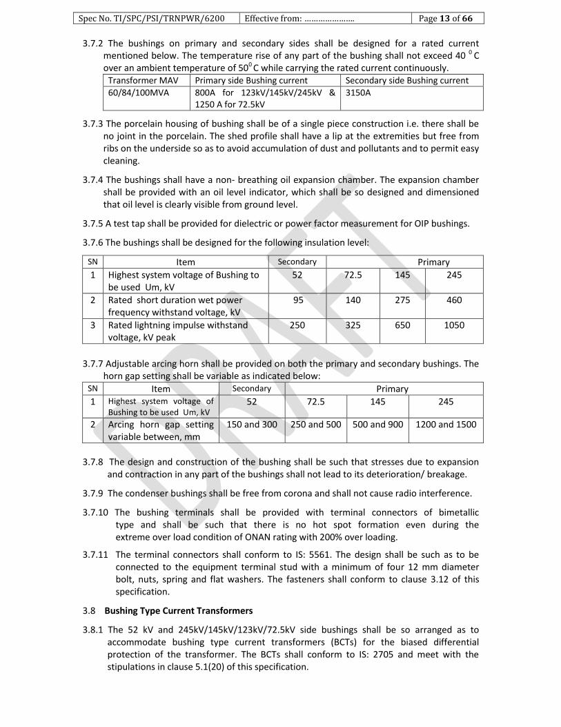
3.7.2 The bushings on primary and secondary sides shall be designed for a rated current mentioned below. The temperature rise of any part of the bushing shall not exceed 40 0 C over an ambient temperature of 500 C while carrying the rated current continuously.
Transformer MAV Primary side Bushing current Secondary side Bushing current
60/84/100MVA 800A for 123kV/145kV/245kV & 1250 A for 72.5kV
3150A
3.7.3 The porcelain housing of bushing shall be of a single piece construction i.e. there shall be no joint in the porcelain. The shed profile shall have a lip at the extremities but free from ribs on the underside so as to avoid accumulation of dust and pollutants and to permit easy cleaning.
3.7.4 The bushings shall have a non- breathing oil expansion chamber. The expansion chamber shall be provided with an oil level indicator, which shall be so designed and dimensioned that oil level is clearly visible from ground level.
3.7.5 A test tap shall be provided for dielectric or power factor measurement for OIP bushings.
3.7.6 The bushings shall be designed for the following insulation level:
SN Item Secondary Primary
1 Highest system voltage of Bushing to be used Um, kV
52 72.5 145 245
2 Rated short duration wet power frequency withstand voltage, kV
95 140 275 460
3 Rated lightning impulse withstand voltage, kV peak
250 325 650 1050
3.7.7 Adjustable arcing horn shall be provided on both the primary and secondary bushings. The horn gap setting shall be variable as indicated below:
SN Item Secondary Primary
1 Highest system voltage of Bushing to be used Um, kV
52 72.5 145 245
2 Arcing horn gap setting variable between, mm
150 and 300 250 and 500 500 and 900 1200 and 1500
3.7.8 The design and construction of the bushing shall be such that stresses due to expansion
and contraction in any part of the bushings shall not lead to its deterioration/ breakage.
3.7.9 The condenser bushings shall be free from corona and shall not cause radio interference.
3.7.10 The bushing terminals shall be provided with terminal connectors of bimetallic type and shall be such that there is no hot spot formation even during the extreme over load condition of ONAN rating with 200% over loading.
3.7.11 The terminal connectors shall conform to IS: 5561. The design shall be such as to be connected to the equipment terminal stud with a minimum of four 12 mm diameter bolt, nuts, spring and flat washers. The fasteners shall conform to clause 3.12 of this specification.
3.8 Bushing Type Current Transformers
3.8.1 The 52 kV and 245kV/145kV/123kV/72.5kV side bushings shall be so arranged as to accommodate bushing type current transformers (BCTs) for the biased differential protection of the transformer. The BCTs shall conform to IS: 2705 and meet with the stipulations in clause 5.1(20) of this specification.
Spec No. TI/SPC/PSI/TRNPWR/6200 Effective from: …………………. Page 14 of 66
3.8.2 The BCTs shall be so designed as to withstand thermal and mechanical stresses resulting from frequent short circuits experienced by the transformer on which these are fitted.
3.8.3 Apart from the BCTs required for the biased differential protection, a BCT of accuracy class 5 and conforming to IS: 2705, with suitable tappings, shall be mounted inside one of the bushings of the left hand side (as viewed from the secondary terminals side) secondary winding (which feed the catenary and would carry a higher current in service as compared to the other secondary windings which feeds the feeder) of each ‘M’ and ‘T’ phases for use with the winding temperature indicators.
3.8.4 The BCTs and the bushings shall be so mounted that removal of a bushing without disturbing the current transformers, terminals and connections or pipe work is easy and convenient.
3.8.5 The leads from the BCTs shall be terminated in terminal boxes provided on the bushing turrets. Suitable links shall be provided in the terminal boxes for shorting the secondary terminals of the BCTs, when not connected to the external measuring circuits.
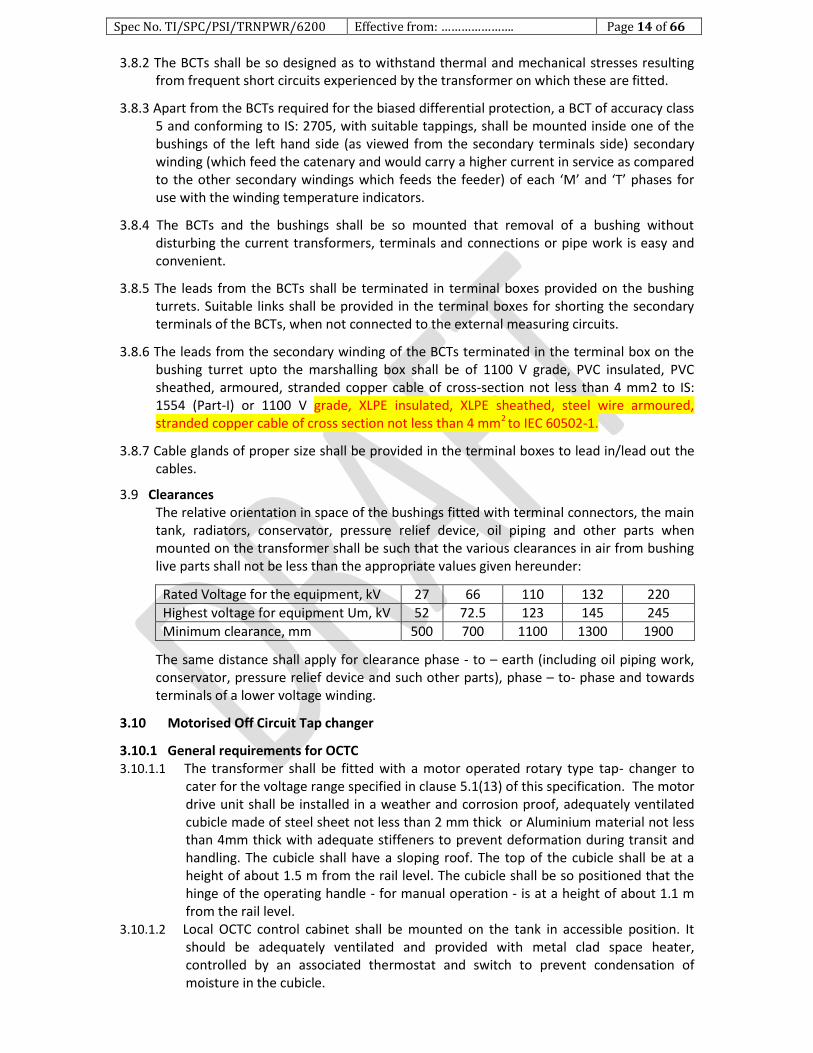
3.8.6 The leads from the secondary winding of the BCTs terminated in the terminal box on the bushing turret upto the marshalling box shall be of 1100 V grade, PVC insulated, PVC sheathed, armoured, stranded copper cable of cross-section not less than 4 mm2 to IS: 1554 (Part-I) or 1100 V grade, XLPE insulated, XLPE sheathed, steel wire armoured, stranded copper cable of cross section not less than 4 mm2 to IEC 60502-1.
3.8.7 Cable glands of proper size shall be provided in the terminal boxes to lead in/lead out the cables.
3.9 Clearances The relative orientation in space of the bushings fitted with terminal connectors, the main tank, radiators, conservator, pressure relief device, oil piping and other parts when mounted on the transformer shall be such that the various clearances in air from bushing live parts shall not be less than the appropriate values given hereunder:
Rated Voltage for the equipment, kV 27 66 110 132 220
Highest voltage for equipment Um, kV 52 72.5 123 145 245
Minimum clearance, mm 500 700 1100 1300 1900
The same distance shall apply for clearance phase - to – earth (including oil piping work, conservator, pressure relief device and such other parts), phase – to- phase and towards terminals of a lower voltage winding.
3.10 Motorised Off Circuit Tap changer
3.10.1 General requirements for OCTC 3.10.1.1 The transformer shall be fitted with a motor operated rotary type tap- changer to
cater for the voltage range specified in clause 5.1(13) of this specification. The motor drive unit shall be installed in a weather and corrosion proof, adequately ventilated cubicle made of steel sheet not less than 2 mm thick or Aluminium material not less than 4mm thick with adequate stiffeners to prevent deformation during transit and handling. The cubicle shall have a sloping roof. The top of the cubicle shall be at a height of about 1.5 m from the rail level. The cubicle shall be so positioned that the hinge of the operating handle - for manual operation - is at a height of about 1.1 m from the rail level.
3.10.1.2 Local OCTC control cabinet shall be mounted on the tank in accessible position. It should be adequately ventilated and provided with metal clad space heater, controlled by an associated thermostat and switch to prevent condensation of moisture in the cubicle.

Spec No. TI/SPC/PSI/TRNPWR/6200 Effective from: …………………. Page 15 of 66
3.10.1.3 All wiring in the cubicle shall be clearly identified by lettered/ figured ferrules of the interlock type, preferably of yellow colour with black letters/ figures. The AC and DC circuits shall be clearly distinguished.
3.10.1.4 Suitable legend and schematic diagram plates made of stainless steel or anodised aluminium with black lettering and lines shall be fixed on the inside surface of the cubicle door.
3.10.1.5 A tap position indicator shall be provided to indicate the tap position which shall be clearly visible to an operator standing on the ground.
3.10.1.6 Operating mechanism for off load tap changer shall be designed to go through one step of tap changer per command. Subsequent tap changes shall be initiated only by a new or repeat command.
3.10.1.7 Limit switches shall be provided to prevent overrunning of the mechanism and shall be directly connected in the circuit of the operating motor. In addition, a mechanical stop shall be provided to prevent over-running of the mechanism under any condition.
3.10.1.8 A five digit non-resettable type counter shall be fitted to the tap changing equipment to indicate the number of operations completed.
3.10.1.9 Tap Changer shall be 110V DC Motor operated as well as remote operation and external handle for manual hand operation.
3.10.1.10 The tap- changer motor shall be suitable for operation off 110 V DC from a battery. The voltage at the battery terminals may vary between 110% and 85% of the normal value. The voltage at the tap- changer motor terminals is likely to be less than 85% of the normal value of 110 V DC due to voltage drop in control cable.
3.10.1.11 It shall not be possible for any two controls to be in operation at the same time.
3.10.1.12 Once the tap changing operation has been initiated and the power supply goes off, OCTC should not stay in between and has to complete the Tap change event once the power supply is restored.
3.10.1.13 The tap - changer shall be provided with suitable interlocking arrangement to prevent its operation (including manual tap changing) when either one or both circuit breakers on the primary as well as on the secondary sides of the transformer is/are in closed condition.
3.10.1.14 The variation of taps shall be in in steps of 5% each to give rated secondary voltage for variation in primary voltage of + 10% to -15%. The principle tap shall be on tap no. 3. There shall be 2 Taps for higher input voltage and 3 taps for lower input voltage variation.
3.10.2 OCTC Control of Transformers
3.10.2.1 The tap - changer and its control circuit shall be designed for operation from the remote control centre (RCC) by the traction power controller (TPC) as well as from the tap changer cubicle and RTCC panel. It shall be provided with necessary interface for its remote control through SCADA. The control feature shall provide the following:
3.10.2.2 Local Electrical Control
a. Local – Remote selector switch shall be provided in the local tap changer control cabinet. It shall control the tap changers as follows:
(i) When the selector switch is in the local position, it shall be possible to operate the ‘raise-lower’ commands locally. Remote control of the raise-lower functions shall be prevented.
(ii) When the selector switch is in remote position, the local operation of raise lower switches shall be in- operative. Remote control of the raise/lower function shall be possible from the Remote Tap Changer Control Panel (RTCC).
Spec No. TI/SPC/PSI/TRNPWR/6200 Effective from: …………………. Page 16 of 66
b. A ‘raise –lower’ control switch/push button shall be provided in the local tap changer control cabinet. This switch shall be operative only when ‘local remote’ selector switch is in ‘local’ position.
c. An OFF-ON switch shall be provided in the local tap changer control cabinet of the transformer. The tap changer shall be in- operative in the OFF position of the switch.
3.10.2.3 Manual Control The cranking device for manual operation of the tap changer gear shall be removable and
suitable for operation by a man standing at ground level. The mechanism shall be complete with the following:
a. Mechanical tap position indicators shall be clearly visible from near the transformer. b. A mechanical operation counter. c. Mechanical stops to prevent over cranking of the mechanism beyond the extreme tap
positions. d. The manual control considered as back to the motor operated load tap changer control
shall be interlocked with the motor to block motor start- up during manual operation. The manual operating mechanism shall be labeled to show the direction of operation for raising/lowering.
3.11 Cooling Equipment
3.11.1 The transformer shall be designed for ONAN/ONAF/OFAF type of cooling.
3.11.2 The radiators shall consist of a pressed steel plate assembly formed into elliptical oil channels (as per Indian Electrical & Electronic Manufacturers Association's (IEEMA) standard) or a series of separate elliptical tubes. The radiators shall be designed in such a manner that the temperature - rise limits specified under Clause 5.1(14) of this specification are not exceeded. Collector/ header pipes in the radiators are to be ERW pipes of thickness 4.5 mm. The external painting of the radiator has to be as per clause 3.13 of this specification. The radiators & accessories should be given external paint coats. First coat of epoxy zinc rich (having minimum 83% zinc) primer (50 micron thickness), intermediate coat of epoxy chemical and corrosion resistant High Build Epoxy Intermediate paint (100 micron thickness) and final coat of Glossy Aliphatic Acrylic Polyurethane Coating paint (50 micron thickness). The total dry film thickness of the paints shall be minimum 200 micron. The shade of paint shall be gray as shade 631 of IS: 5.
3.11.3 The radiators shall be removable (after isolating the same from the main tank) to facilitate transportation of the transformer. A drain plug of size 19 mm and an air - release plug of size 19 mm shall be provided at the bottom and at the top of each radiator bank for draining and filling of oil respectively. Each radiator bank shall also be provided with shut - off valves of size 80 mm. In case of use of headers, isolating valves of size 80mm shall be used between tank and headers.
3.11.4 The radiators shall preferably be supported directly on the transformer tank. Each radiator bank shall be fitted with two hooks, one at the centre for lifting the radiator and the other for tying the unit in service.
3.11.5 Each Transformer with ONAF rating shall be provided with two completely independent
groups of cooler fan banks, each of 50% capacity having 25% additional fans in each
group as stand by (Subject to minimum of one cooler fan per group). Fans and blowers
for air blast cooling shall be mounted so as to ensure that no damage to radiators can
arise from vibration of the fans.

Spec No. TI/SPC/PSI/TRNPWR/6200 Effective from: …………………. Page 17 of 66
3.11.6 Cooler System shall be provided such that both groups of fans shall start independently
at different temperatures. The control circuit shall also enable switching/changeover of
designation of one group of fan to another so that the groups can be interchanged. The
standby fans shall be switched on automatically in case of failure of equivalent cooler
fans in that group of coolers respectively.
3.11.7 Air blower shall be suitable to start direct on line. Air blower shall be designated so that
they operate with a minimum of noise or humming. It shall be possible to remove the
blower complete with motor without disturbing or dismantling the cooler structure
frame work.
3.11.8 Blades shall be suitably painted for outdoor use. For fans, painted wire mesh guards, with
mesh not greater than 25mm shall be provided to prevent accidental contact with
blades. Fans mounted shall be provided with outside guards against birdage. Guards shall
be provided over all moving shafts and couplings.
3.11.9 Manufacturer shall specify the loading capacity of transformer in case of failure of one or more fans. Provision should be made to avoid hunting of fans.
3.11.10 For OFAF rating the cooling system shall in addition contain electric motor driven oil pump having 100% stand by capacity. Stand by fan and electric motor driver oil pump shall come into operation automatically in the event of failure of any fan or oil pump in the bank.
3.11.11 The oil circuit of all cooler banks shall be provided with oil flow indicators, shut off valves lifting lugs top and bottom oil filtering valves, air release plugs, drain valve and thermometer pockets fitted with captive screw cap on the inlet/outlet branches of each separately mounted cooler bank
3.11.12 Cooling fans for each unit shall be housed in fan box to prevent ingress of rain water. Each fan shall be suitably protected by galvanized wire mesh guard.
3.11.13 Centrifugal oil pump shall be used. Measures shall be taken to prevent mal-operation of Buchholz relay when all oil pumps are simultaneously put into service. The pump shall be so designed that pump impeller will not restrict the natural circulation of oil, when the pump is not in use/ operation.
3.11.14 Cooling fan and oil pump motors with ‘F’ class insulation shall be suitable for operation on 230 volt, single phase, 50 cycle power supply with variation in supply voltage and frequency.
3.11.15 An oil flow indicator with alarm contacts shall be provided in each oil pump circuit to indicate flow of oil in the normal direction and to actuate an alarm if the flow of oil is stopped or is in reverse direction.
3.11.16 The coolers and its accessories shall preferably be hot dip galvanized or corrosion resistant paint should be applied to it.
3.12 CONTROL OF COOLER OPERATION
3.12.1 Cooler units shall be suitable for operation with a 240Volts, Single Phase, 50Hz power supply.
3.12.2 The cooler fans shall come into service through contact of winding temperature indicator at predetermined temperature of transformer winding. The temperature setting for operation of fan and oil pump shall be adjustable over a reasonable range. Hunting of the transformer cooling equipment shall be avoided by providing suitable
Spec No. TI/SPC/PSI/TRNPWR/6200 Effective from: …………………. Page 18 of 66
range settings. Separate winding temperature indicator with necessary contacts shall be provided and housed in local control kiosk for control of pumps and fans.
3.12.3 Suitable manual control facility for cooler fans and oil pumps shall also be furnished.
3.12.4 For control of cooler fans and oil pumps separate weather and vermin proof control cubicle shall be furnished and installed near the transformer.
3.12.5 Control equipment for fan motors and oil pump shall be mounted in a marshaling box adjacent to the transformer and shall include necessary electrically operated contactor and with control gear of suitable design both for starting and stopping the motors & pump manually and also automatically from the contacts of the Winding Temperature indicating device. Overload and other necessary protections shall be provided as per requirement. A no volt relay shall also be fitted. MCB shall be provided for the main supply. The temperature of the transformer winding at which the fan and oil pump will come into service shall be indicated along with the range of adjustments available in the system.
3.12.6 The cooling equipment shall have provision for visual/alarm indication for the following in the control equipment on the transformer remote tap changer control panel (RTCC) to be supplied by the firm.
i) The Auto/Manual position of the selector switch for the cooling equipment.
ii) That the first set of contacts of the winding temperature indicator has closed.
iii) That the second set of contacts of the winding temperature indicator has closed.
iv) Fans of first group ‘ON’ indication.
v) Fans of second group ‘ON’ indication.
vi) Standby fan in first group ‘ON’ indication.
vii) Standby fan in second group ‘ON’ indication.
viii) Electric motor driver oil pumps ‘ON’ indication.
ix) Stand by Electric motor driver oil pump ‘ON’ indication.
3.13 Fasteners
All fasteners of 12 mm diameter and less exposed to atmosphere shall be of stainless steel and those above 12 mm diameter shall preferably be of stainless steel or mild steel hot dip galvanized to 610 g / m2 of zinc. The material of the stainless steel fasteners shall conform to IS: 1570 (Part- V). Grade 04Cr17Ni12Mo2.
3.14 Painting
3.15.1 Shot blasting / sand blasting shall be done on the transformer tank to remove all scales, rust and other residue before applying the paint inside the tank. All steel surfaces which are in contact with insulating oil shall be painted with heat resistant oil insoluble insulating varnish.
3.15.2 All steel surfaces exposed to weather shall be properly descaled/grit blasted. The epoxy and polyurethane protective paints as per ISO/EN 12944 have to be provided for proper protection against corrosive and coastal environments and give life of approx. 12-15 years. All the external surfaces of the Transformer shall be given first coat of epoxy zinc rich (having minimum 83% metallic zinc) primer (50 micron thickness), intermediate coat of epoxy chemical and corrosion resistant High Build Epoxy Intermediate paint (100 micron thickness) and final coat of Glossy Aliphatic Acrylic Polyurethane Coating paint (50 micron thickness). The total dry film thickness of the paints shall be minimum 200 micron. The shade of paint shall be gray as shade 631 of IS: 5. Same paints have to be applied at damaged surfaces, if any, at site during erection /commissioning of the
Spec No. TI/SPC/PSI/TRNPWR/6200 Effective from: …………………. Page 19 of 66
transformer. One final coat of polyurethane paint has to be applied to ensure proper smoothness and finish.
3.15.3 For panels like marshalling Box, OCTC drive mechanism box and RTCC panels Powder Coating painting of minimum 80 micron thickness is to be done. The shade of paint shall be
shade 631 of IS: 5 for the marshalling Box, OCTC drive mechanism box and shade 216 of IS: 5 for the RTCC Panel.
4.0 List of Related specifications
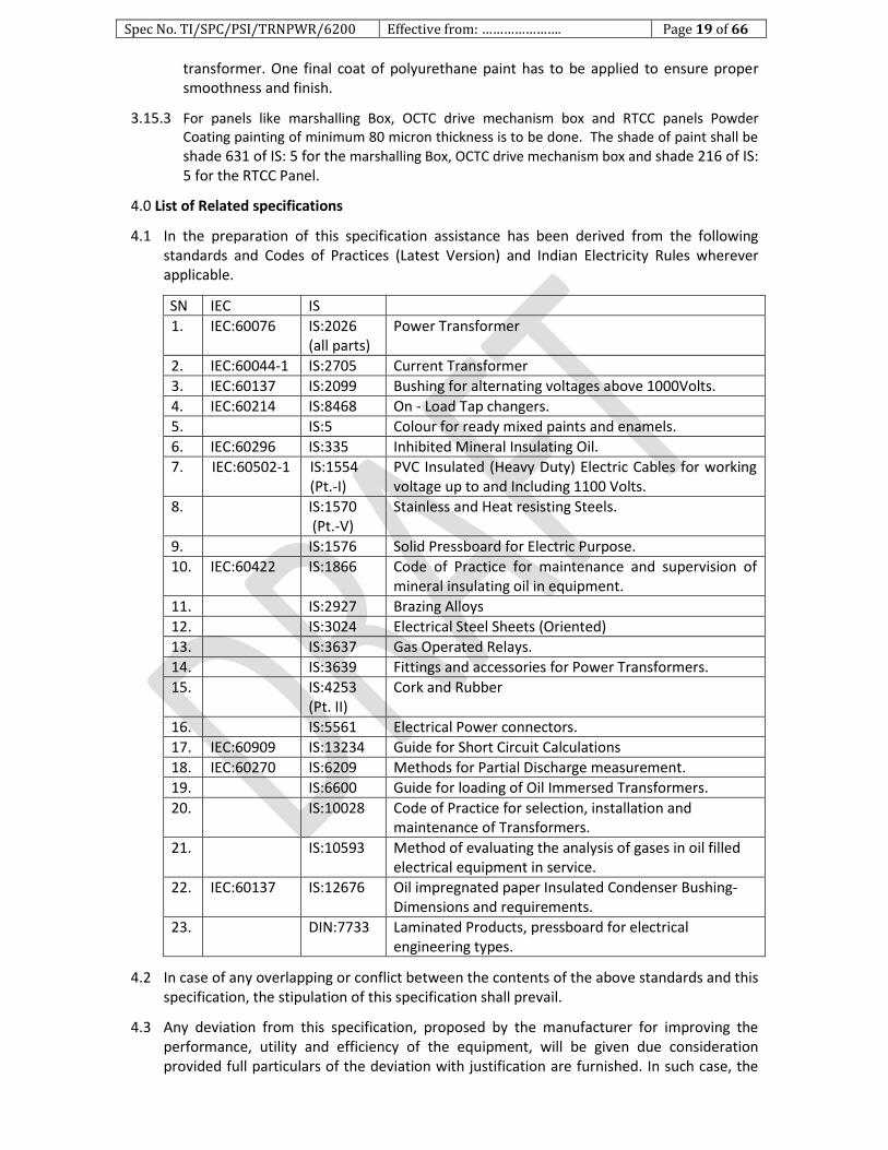
4.1 In the preparation of this specification assistance has been derived from the following standards and Codes of Practices (Latest Version) and Indian Electricity Rules wherever applicable.
SN IEC IS
1. IEC:60076 IS:2026 (all parts)
Power Transformer
2. IEC:60044-1 IS:2705 Current Transformer
3. IEC:60137 IS:2099 Bushing for alternating voltages above 1000Volts.
4. IEC:60214 IS:8468 On - Load Tap changers.
5. IS:5 Colour for ready mixed paints and enamels.
6. IEC:60296 IS:335 Inhibited Mineral Insulating Oil.
7. IEC:60502-1 IS:1554 (Pt.-I)
PVC Insulated (Heavy Duty) Electric Cables for working voltage up to and Including 1100 Volts.
8. IS:1570 (Pt.-V)
Stainless and Heat resisting Steels.
9. IS:1576 Solid Pressboard for Electric Purpose.
10. IEC:60422 IS:1866 Code of Practice for maintenance and supervision of mineral insulating oil in equipment.
11. IS:2927 Brazing Alloys
12. IS:3024 Electrical Steel Sheets (Oriented)
13. IS:3637 Gas Operated Relays.
14. IS:3639 Fittings and accessories for Power Transformers.
15. IS:4253 (Pt. II)
Cork and Rubber
16. IS:5561 Electrical Power connectors.
17. IEC:60909 IS:13234 Guide for Short Circuit Calculations
18. IEC:60270 IS:6209 Methods for Partial Discharge measurement.
19. IS:6600 Guide for loading of Oil Immersed Transformers.
20. IS:10028 Code of Practice for selection, installation and maintenance of Transformers.
21. IS:10593 Method of evaluating the analysis of gases in oil filled electrical equipment in service.
22. IEC:60137 IS:12676 Oil impregnated paper Insulated Condenser Bushing- Dimensions and requirements.
23. DIN:7733 Laminated Products, pressboard for electrical engineering types.
4.2 In case of any overlapping or conflict between the contents of the above standards and this specification, the stipulation of this specification shall prevail.
4.3 Any deviation from this specification, proposed by the manufacturer for improving the performance, utility and efficiency of the equipment, will be given due consideration provided full particulars of the deviation with justification are furnished. In such case, the
Spec No. TI/SPC/PSI/TRNPWR/6200 Effective from: …………………. Page 20 of 66
manufacturer shall quote according to this specification and the deviations, if any, proposed by him shall be quoted as alternate/alternatives.
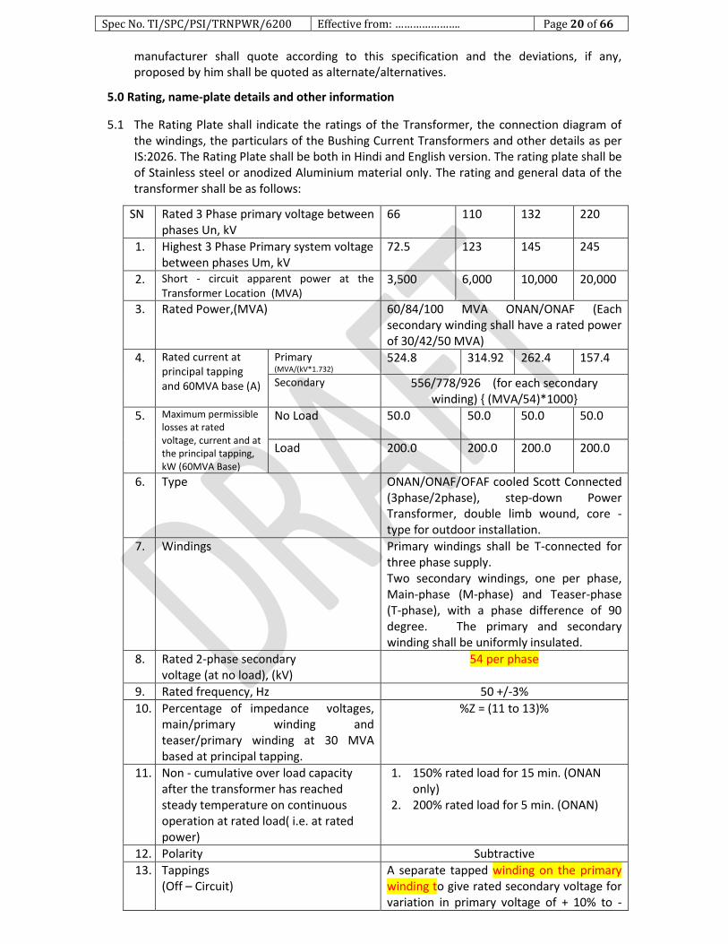
5.0 Rating, name-plate details and other information
5.1 The Rating Plate shall indicate the ratings of the Transformer, the connection diagram of the windings, the particulars of the Bushing Current Transformers and other details as per IS:2026. The Rating Plate shall be both in Hindi and English version. The rating plate shall be of Stainless steel or anodized Aluminium material only. The rating and general data of the transformer shall be as follows:
SN Rated 3 Phase primary voltage between phases Un, kV
66 110 132 220
1. Highest 3 Phase Primary system voltage between phases Um, kV
72.5 123 145 245
2. Short - circuit apparent power at the Transformer Location (MVA)
3,500 6,000 10,000 20,000
3. Rated Power,(MVA) 60/84/100 MVA ONAN/ONAF (Each secondary winding shall have a rated power of 30/42/50 MVA)
4. Rated current at principal tapping and 60MVA base (A)
Primary (MVA/(kV*1.732)
524.8 314.92 262.4 157.4
Secondary 556/778/926 (for each secondary winding) (MVA/54)*1000
5. Maximum permissible losses at rated voltage, current and at the principal tapping, kW (60MVA Base)
No Load 50.0 50.0 50.0 50.0
Load 200.0 200.0 200.0 200.0
6. Type ONAN/ONAF/OFAF cooled Scott Connected (3phase/2phase), step-down Power Transformer, double limb wound, core -type for outdoor installation.
7. Windings Primary windings shall be T-connected for three phase supply. Two secondary windings, one per phase, Main-phase (M-phase) and Teaser-phase (T-phase), with a phase difference of 90 degree. The primary and secondary winding shall be uniformly insulated.
8. Rated 2-phase secondary voltage (at no load), (kV)
54 per phase
9. Rated frequency, Hz 50 +/-3%
10. Percentage of impedance voltages, main/primary winding and teaser/primary winding at 30 MVA based at principal tapping.
%Z = (11 to 13)%
11. Non - cumulative over load capacity after the transformer has reached steady temperature on continuous operation at rated load( i.e. at rated power)
1. 150% rated load for 15 min. (ONAN only)
2. 200% rated load for 5 min. (ONAN)
12. Polarity Subtractive
13. Tappings (Off – Circuit)
A separate tapped winding on the primary winding to give rated secondary voltage for variation in primary voltage of + 10% to -
Spec No. TI/SPC/PSI/TRNPWR/6200 Effective from: …………………. Page 21 of 66
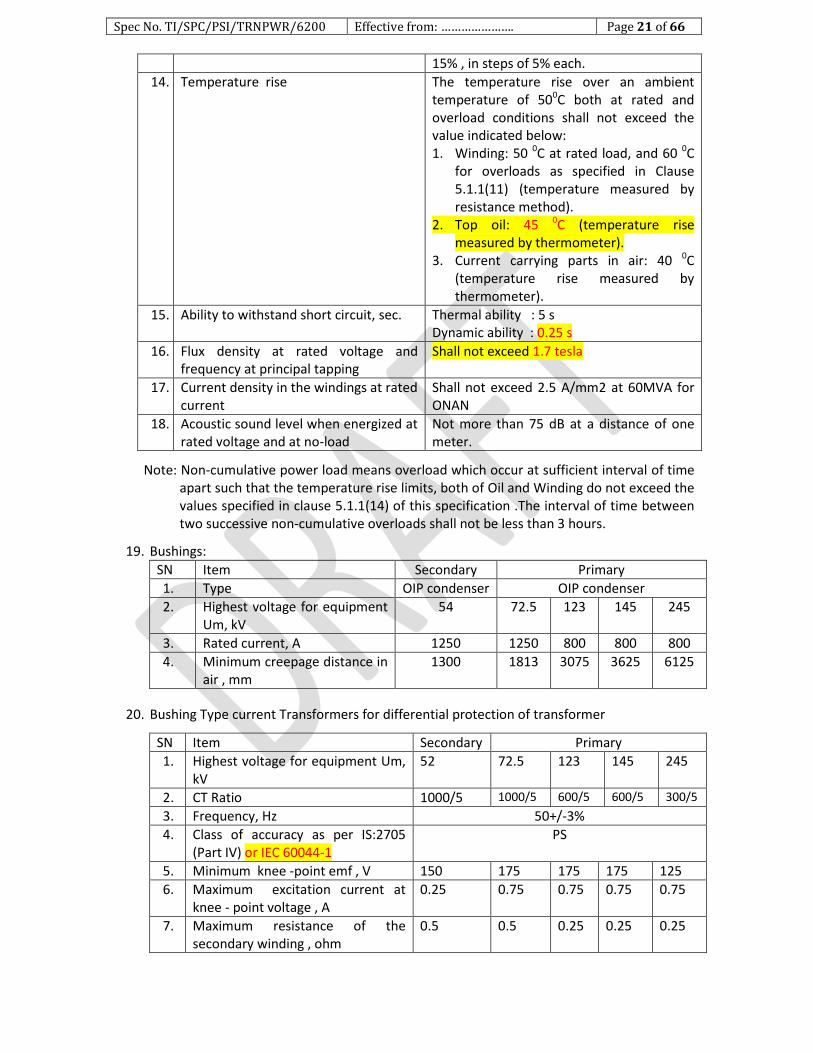
15% , in steps of 5% each.
14. Temperature rise The temperature rise over an ambient temperature of 500C both at rated and overload conditions shall not exceed the value indicated below: 1. Winding: 50 0C at rated load, and 60 0C
for overloads as specified in Clause 5.1.1(11) (temperature measured by resistance method).
2. Top oil: 45 0C (temperature rise measured by thermometer).
3. Current carrying parts in air: 40 0C (temperature rise measured by thermometer).
15. Ability to withstand short circuit, sec. Thermal ability : 5 s Dynamic ability : 0.25 s
16. Flux density at rated voltage and frequency at principal tapping
Shall not exceed 1.7 tesla
17. Current density in the windings at rated current
Shall not exceed 2.5 A/mm2 at 60MVA for ONAN
18. Acoustic sound level when energized at rated voltage and at no-load
Not more than 75 dB at a distance of one meter.
Note: Non-cumulative power load means overload which occur at sufficient interval of time apart such that the temperature rise limits, both of Oil and Winding do not exceed the values specified in clause 5.1.1(14) of this specification .The interval of time between two successive non-cumulative overloads shall not be less than 3 hours.
19. Bushings:
SN Item Secondary Primary
1. Type OIP condenser OIP condenser
2. Highest voltage for equipment Um, kV
54 72.5 123 145 245
3. Rated current, A 1250 1250 800 800 800
4. Minimum creepage distance in air , mm
1300 1813 3075 3625 6125
20. Bushing Type current Transformers for differential protection of transformer
SN Item Secondary Primary
1. Highest voltage for equipment Um, kV
52 72.5 123 145 245
2. CT Ratio 1000/5 1000/5 600/5 600/5 300/5
3. Frequency, Hz 50+/-3%
4. Class of accuracy as per IS:2705 (Part IV) or IEC 60044-1
PS
5. Minimum knee -point emf , V 150 175 175 175 125
6. Maximum excitation current at knee - point voltage , A
0.25 0.75 0.75 0.75 0.75
7. Maximum resistance of the secondary winding , ohm
0.5 0.5 0.25 0.25 0.25
Spec No. TI/SPC/PSI/TRNPWR/6200 Effective from: …………………. Page 22 of 66
6. 0 Testing of Transformer
6.1 General
6.1.1 Once the design and drawings as well as QAP have been approved and a written advice has been given by RDSO, the manufacturer shall take up manufacture of the prototype for inspection/testing by RDSO. It is to be clearly understood that any changes or modification by the above authorities to be done on the prototype the same shall be done expeditiously, notwithstanding approval having already been given for the designs and drawings.
6.1.2 Prior to giving a call to the purchase/DG(TI), RDSO, Lucknow for inspection and testing of the prototype, the manufacturer shall submit a detailed test schedule consisting of schematic circuit diagrams for each of the tests and the number of days required to complete all the tests at one stretch. Once the schedule is approved, the tests shall invariably be done accordingly. However, during the process of type testing or even later, the DG/TI/RDSO, Lucknow reserves the right to conduct any additional test(s), besides those specified herein, on any equipment/item so as to test the equipment/item to his satisfaction or for gaining additional information and knowledge. In case any dispute or disagreement arises between the manufacturer and the representative of the DG/TI/RDSO, Lucknow during the process of testing as regards the procedure for type tests and/or the interpretation and acceptability of the results of type tests, it shall be brought to the notice of the DG/TI/RDSO, Lucknow as the case may be whose decision shall be final and binding. Only after the prototype of the equipment is manufactured and ready in all respects, shall the manufacturer give the actual call for the inspection and testing with at least 15 days notice for the purpose.
6.1.3 Type tests shall be carried out on prototype unit of Traction power Transformer with relevant standards as modified or amplified by this specification where applicable at the works of the manufacturer or at a reputed testing laboratory. At the works of the manufacturer the testing shall be conducted in the presence of the authorised representative of the purchaser/DG (TI)/RDSO, Lucknow. However for the tests in the third party laboratory the presence of representative of the purchaser/DG (TI)/RDSO, Lucknow may be decided by the RDSO.
6.2 Tests during Manufacture
6.2.1 Though the tests described below shall form a part of the type tests, the manufacture shall carry out these tests on each and every unit during the process of manufacture and submit the test reports to the Purchaser's Inspector deputed for witnessing the routine tests. However, the ‘Vacuum test’ described under clause 6.2.1.2 and ‘Pressure test’ at clause no. 6.2.1.3 shall be conducted only on the prototype unit.
1. Oil leakage test. 2. Vacuum test. 3. Pressure test. 4. Insulation test for core bolts. 5. Test for pressure relief device. 6. Measurement of Capacitance and tan delta values
6.2.1.1 Oil leakage test: The transformer with its radiators, conservator tank and other parts, fittings and accessories completely assembled shall be tested for oil leakage by being filled with oil conforming to IS: 335, type-II (Para 6.3.8.9 of this specification) at the ambient temperature and subjected to a pressure corresponding to twice the normal static oil head or to the normal static oil head plus 35 kN/m2 (0.35 kgf/cm2), whichever is lower, the static oil head being measured at the base of the tank. This pressure shall be maintained for a period of not less than 12 h, during which time no leakage shall occur.

Spec No. TI/SPC/PSI/TRNPWR/6200 Effective from: …………………. Page 23 of 66
6.2.1.2 Vacuum test: The transformer tank only shall be tested at a vacuum of 3.33 kN/m2 (0.0333 kgf/cm2) for 60 min. The permanent deflection of flat plates after release of vacuum shall not exceed the values specified below:
Horizontal length of flat plate Permanent deflection, mm
Upto and including 750 mm 5.0
751 mm to 1250 mm 6.5
1251mm to 1750 mm 8.0
1751 mm to 2000 mm 9.5
2001 mm to 2250 mm 11.0
2251 mm to 2500 mm 12.5
2501 mm to 3000 mm 16.0
Above 3000 mm 19.0
6.2.1.3 Pressure test: Every transformer tank, radiator and conservator tank shall be subjected to an air pressure corresponding to twice the normal static head of oil or to the normal static head of oil or to the normal static oil head pressure plus 35 kN/m2 (0.35 kgf/cm2), whichever is lower, as measured at the base of the tank. The pressure shall remain constant for 1 h to indicate that there is no leakage.
6.2.1.4 Insulation test for core bolts: This test shall be done as described in Clause 3.4.4 of this specification.
6.2.1.5 Test for pressure relief device: Every pressure relief device shall be subjected to gradually increasing oil pressure. It shall operate before the pressure reaches the test pressure specified in Clause 6.2.1.3 hereof and the value at which it has operated shall be recorded.
6.2.1.6 Measurement of Capacitance and Tan-Delta values: The measurement of capacitance and tan-Delta (Dielectric Loss factor) of the Transformer windings shall be made by Schering Bridge.
6.2.2 During the prototype approval, at following manufacturing stages the tests may be witnessed by the representative of the purchaser /DG (TI), RDSO, Lucknow at the works of the manufacturer.
6.2.2.1 Motorised off Circuit Tap Changer 6.2.2.2 Fire Extinguishing System 6.2.2.3 Transformer Tank 6.2.2.4 Transformer CORE. 6.2.2.5 Transformer winding Assembly
Tests to be conducted during these manufacturing stages are as detailed below;
6.2.2.1 A. Motorised off Circuit tap changer: Following tests shall be conducted (i) Visual and dimensions check: Visual and dimensions check of the complete Motor Drive
unit (MDU) of the Off Circuit tap Changer shall be carried out as per the approved drawings and requirements mentioned in the clause no. 3.10 of this specification.
(ii) Mechanical Endurance test: The off circuit tap changer shall be fully assembled and subjected for 1000 operations without any failures. An operation shall comprise moving the tap changer from one tap position to the next higher or lower tap position. At the minimum voltage of 93.5V DC : 250 operations.
At the maximum voltage of 121V DC : 250 operations. At the rated voltage of 110V DC : 500 operations.
(iii) Contact resistance Measurement: Contact resistance at every tap position shall be measured before and after endurance test. Contact resistance shall be less than 2 milli ohm.

Spec No. TI/SPC/PSI/TRNPWR/6200 Effective from: …………………. Page 24 of 66
(iv) Operation check of the tap changer with drive mechanism: The Off circuits tap changer
(OCTC) and the respective Drive mechanism shall be checked for 2 complete cycle of
operation - The operation shall be smooth without any abnormal sound.
(v) HV Test on auxiliary Circuit. All auxiliary circuits shall be subjected to a separate source AC withstand test of 2kV for 1 minute between all live terminals and the frame/earth. - Equipment should withstand the test.
(vi) Pressure test:
For in tank type tap changer: Pressure test on top head cover shall be conducted at 12PSI for six hour.
For out tank type tap changer: Pressure test of oil compartment shall be conducted at 12psi for six hour.
At the end of the test no pressure drop/leakage shall be observed.
(vii) It shall be verified that once the tap changing operation has been initiated and the power supply (110V DC) goes off, OCTC should not stay in between and has to complete the Tap change event once the power supply is restored.
(viii) Manual Operation: Five complete raise and lower operation shall be verified with manual handle.
(ix) Type tests reports of the tap changer of the type tests as per IEC: 60214/IS: 8468 shall be submitted (Clause no. 6.3.8.1 of this specification).
6.2.2.2 Fire Extinguishing System: The tests shall be conducted as mentioned in the NIFPES specification at Annexure-1.
6.2.2.3 Transformer Tank: following tests shall be conducted: (i) The pressure test and vacuum test shall be done as per the clause no. 6.2.1.2 &
6.2.1.3 of this specification. (ii) The Dye Penetration (DP) Test at the jacking and lifting pads.
6.2.2.4 Transformer CORE. (i) 2 kV r. m. s. withstand voltage between Core clamping bolts and core laminations
for duration of 60 seconds. (ii) Stack height, Diameter and window dimensions as per the approved drawings. (iii) The manufacturer test certificate of the CORE material shall be submitted.
6.2.2.5 Transformer Winding Assembly: Following measurements/inspection shall be conducted on HV, LV & Regulating windings. (i) Thickness of the bare and insulated conductor. (ii) Width and Thickness of the conductor. The ratio of width to thickness of copper
conductor used for winding shall not exceed 5:1. (iii) Number and location of Probes for Fiber Optic Temperature Measurement. The
Transformer manufacturer should submit the details that the probes are located in the hottest point of the winding.
6.2.3 The requirement of the stage inspection (CHP) by RDSO for OCTC and NIFPES may be waived off subject to the following: (i) Earlier RDSO has witnessed the item at the works of manufacturer and
manufacturer submits a declaration that the design of manufactured unit is identical to that, which has been witnessed by RDSO.
(ii) The transformer manufacturer has witnessed the unit as per the tests/formats mentioned in the specification.
6.2.4 The purchaser or their representative may, if he so desires, carry out any checks or tests on the quality of manufacture at any stage during coil winding, drying of coils, assembly of coils on core and method of drying, vacuum impregnation, tightness of core clamping

Spec No. TI/SPC/PSI/TRNPWR/6200 Effective from: …………………. Page 25 of 66
bolts, adequacy of pressure on coils or any other aspects as deemed so as to ensure that proper quality is maintained.
6.3 TYPE TESTS
The type tests shall be carried out on the prototype transformer at the works of the manufacturer or at any reputed laboratory in the presence of the representative of the purchaser /DG (TI), RDSO, Lucknow, and in accordance with the relevant specifications and as altered, amended or supplemented by this specification. The following shall constitute the type tests:
1. Temperature - rise test. 2. Lightning impulse test. 3. Test with lightning impulse, chopped on the tail. 4. Short - circuit test. 5. Measurement of acoustic sound level. 6. Measurement of partial discharge quantity. 7. Measurement of harmonics of no - load current.
6.3.1 Temperature - Rise test
6.3.1.1 The temperature - rise test shall be done with the tap changer on the lowest tap position with IS: 2026 (Part II) or IEC 60076-2 except as modified hereunder:
1. At rated load. 2. At 150% rated load for 15 min after continuous operation at rated load for 1 h. 3. At 200% rated load for 5 min after continuous operation at rated load for 1 h.
6.3.1.2 The points to be ensured during the temperature - rise test shall be:
1. The tests shall be undertaken at transformer on ONAN, ONAF and OFAF ratings. The tests shall be done continuously without any power supply interruption. In case interruptions of power supply do take place for some reason, then the entire test shall: be repeated after steady state conditions are attained.
2. Following tests shall be conducted on the sample of oil drawn from the transformer tank before and after temperature rise tests: i) The Dissolved Gas Analysis (DGA) ii) Specific Resistance iii) Water Content (ppm) iv) Electric strength (BDV)
3. The ambient temperature shall be measured using alcohol in glass thermometers only.
4. The winding temperature shall be determined by the resistance method only. 5. The temperature of the top oil shall be measured by an alcohol in glass
thermometer placed in an oil- filled thermometer pocket. 6. The average oil temperature shall be calculated as the difference between the top
oil temperature and half the temperature drop in the cooling equipment (radiators). 7. The temperature of the hot - spot in the winding shall be the sum of the
temperature of the top oil and 1.1 times the temperature rise of the winding above the average oil temperature.
8. The FOS shall be operational during temperature tests and be demonstrated during these tests. During probe verification, the hottest probes for each phase shall be Identified, and temperature data for all probes recorded and reported in the test report.

Spec No. TI/SPC/PSI/TRNPWR/6200 Effective from: …………………. Page 26 of 66
6.3.1.3 The test shall be carried out as described below:
6.3.1.3.1 100% load
1. A quantum of power equal to the sum of the measured losses viz. No- load loss and load losses measured at lowest tap position, corrected to 750C plus 10% of such sum shall be fed to the primary winding of the transformer with the secondary windings short- circuited.
2. The power so fed to the transformer shall be continuously maintained till such time as the steady state temperature is reached i.e. the top oil temperature rise does not vary by more than 10 C during four consecutive hourly readings.
3. On attaining the steady state temperature, the current in the primary winding of the transformer shall be brought to the rated current which shall be maintained for 1 h. At the end of the period the power supply to the transformer shall be switched off and the time of switching off recorded.
4. The measurement of hot resistance shall commence as soon as possible after switching off. The first reading of the resistance shall be taken before the expiry of 90 s from the instant of switching off and the first ten readings shall be taken at intervals of 15 s apart. Thereafter, another ten readings shall be taken at intervals of 30 s apart.
5. The time at which each of the resistance values is read shall also be recorded.
6. The temperature of the ambient, top oil, the top and bottom radiator header oils shall also be recorded at half - hourly intervals through out the test starting from the instant power supply is switched on to commence the test till it is switched off.
7. The WTI and OTI readings shall also be recorded at half-hourly intervals right from the instant the power supply is switched on to commence the test till it is switched off.
8. After power supply is switched off, the readings of OTI and WTI shall be recorded at intervals of 1 min apart for 30 min.
6.3.1.3.2 150% load
1. After completion of the test at 100 % load, the transformer shall be fed with power, which shall be a value so as to cause circulation of the rated current in the primary winding with secondary windings short - circuited. This current shall be circulated for 1 h.
2. The current shall thereafter be increased to 150% of the rated current and maintained for a period of 15 minute. At the end of the 15 minute period, the power supply shall be switched off and the time of switching off shall be recorded.
3. Thereafter the readings as indicated in Clauses 6.3.1.3.1(4 to 8) shall be recorded.
4. The temperature of ambient, top oil, the top and bottom radiator header oils and the temperatures indicated by OTI and WTI shall also be recorded at the time of switching on 150% load as well as at the time of switching off the power supply.
6.3.1.3.3 200% load
1. After completion of the test at 150 % load, the transformer shall be fed with power, which shall be a value so as to cause circulation of the rated current in the primary winding with secondary windings short - circuited. This current shall be circulated for 1 h.
2. The current shall thereafter be increased to 200% of the rated current and maintained for a period of 5 min. At the end of the 5 min period, the power supply shall be switched off and the time of switching off shall be recorded.
3. Thereafter the readings as indicated in Clauses 6.3.1.3.1 (4 to 8) shall be recorded. 4. The temperature of ambient, top oil, the top and bottom radiator header oils and the
temperatures indicated by OTI and WTI shall also be recorded at the time of switching on 200% load as well as at the time of switching off the power supply.
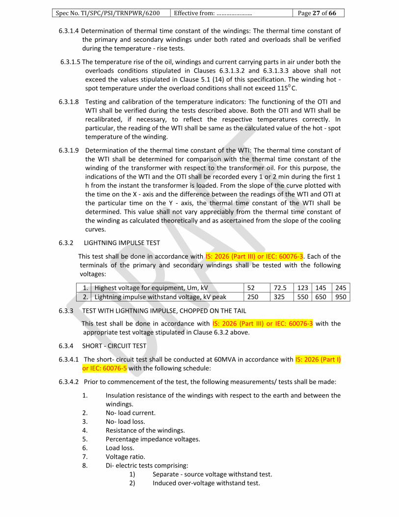
Spec No. TI/SPC/PSI/TRNPWR/6200 Effective from: …………………. Page 27 of 66
6.3.1.4 Determination of thermal time constant of the windings: The thermal time constant of the primary and secondary windings under both rated and overloads shall be verified during the temperature - rise tests.
6.3.1.5 The temperature rise of the oil, windings and current carrying parts in air under both the overloads conditions stipulated in Clauses 6.3.1.3.2 and 6.3.1.3.3 above shall not exceed the values stipulated in Clause 5.1 (14) of this specification. The winding hot - spot temperature under the overload conditions shall not exceed 1150 C.
6.3.1.8 Testing and calibration of the temperature indicators: The functioning of the OTI and WTI shall be verified during the tests described above. Both the OTI and WTI shall be recalibrated, if necessary, to reflect the respective temperatures correctly. In particular, the reading of the WTI shall be same as the calculated value of the hot - spot temperature of the winding.
6.3.1.9 Determination of the thermal time constant of the WTI: The thermal time constant of the WTI shall be determined for comparison with the thermal time constant of the winding of the transformer with respect to the transformer oil. For this purpose, the indications of the WTI and the OTI shall be recorded every 1 or 2 min during the first 1 h from the instant the transformer is loaded. From the slope of the curve plotted with the time on the X - axis and the difference between the readings of the WTI and OTI at the particular time on the Y - axis, the thermal time constant of the WTI shall be determined. This value shall not vary appreciably from the thermal time constant of the winding as calculated theoretically and as ascertained from the slope of the cooling curves.
6.3.2 LIGHTNING IMPULSE TEST
This test shall be done in accordance with IS: 2026 (Part III) or IEC: 60076-3. Each of the terminals of the primary and secondary windings shall be tested with the following voltages:
1. Highest voltage for equipment, Um, kV 52 72.5 123 145 245
2. Lightning impulse withstand voltage, kV peak 250 325 550 650 950
6.3.3 TEST WITH LIGHTNING IMPULSE, CHOPPED ON THE TAIL
This test shall be done in accordance with IS: 2026 (Part III) or IEC: 60076-3 with the appropriate test voltage stipulated in Clause 6.3.2 above.
6.3.4 SHORT - CIRCUIT TEST
6.3.4.1 The short- circuit test shall be conducted at 60MVA in accordance with IS: 2026 (Part I) or IEC: 60076-5 with the following schedule:
6.3.4.2 Prior to commencement of the test, the following measurements/ tests shall be made:
1. Insulation resistance of the windings with respect to the earth and between the windings.
2. No- load current. 3. No- load loss. 4. Resistance of the windings. 5. Percentage impedance voltages. 6. Load loss. 7. Voltage ratio. 8. Di- electric tests comprising:
1) Separate - source voltage withstand test. 2) Induced over-voltage withstand test.
Spec No. TI/SPC/PSI/TRNPWR/6200 Effective from: …………………. Page 28 of 66
9. Recording of recurrent surge oscillogram (RSO) at the highest, lowest and principal tapping.
10. Frequency response analysis (FRA) of the transformer.
6.3.4.3 The test shall preferably be done by closing the breaker on the secondary side after energizing the primary winding at its rated voltage.
6.3.4.4 The transformer shall be subjected to a total of seven shots in the following sequence:
Shot Current
1st shot Asymmetrical and symmetrical currents in M-Phase and T phase respectively at the highest tap.
2nd shot
Symmetrical and asymmetrical currents in M-Phase and T phase respectively at the highest tap.
3rd shot Asymmetrical and symmetrical currents in M-Phase and T phase respectively at the principal tap.
4th shot Symmetrical and asymmetrical currents in M-Phase and T phase respectively at the principal tap.
5th shot Asymmetrical and symmetrical currents in M-Phase and T phase respectively at the lowest tap.
6th shot Symmetrical and asymmetrical currents in M-Phase and T phase respectively at the lowest tap.
7th shot Symmetrical currents in M-Phase and T phase at the lowest tap.
6.3.4.5 The duration of each shot shall be 0.25 s as per IEC:60076
6.3.4.6 Percentage impedance voltage or inductance shall be measured after each shot.
6.3.4.7 Further testing and inspection of the transformer subjected to the short-circuit test shall be carried out as per IS: 2026 (Part-I) or as per IEC:60076 with the modification that:
1. The dielectric routine tests shall be at 100% of the original test value. 2. The percentage impedance voltages measured after the short-circuit test shall not
vary by more than 2% from those measured before the short-circuit test.
6.3.4.8 On completion of the short-circuit test, the transformer shall be untanked for inspection of the core and windings. In case the inspection of the core and windings do not reveal any apparent defects and the results of the short – circuit test, the values of percentage impedance voltages as also the results of the routine tests done after the short-circuit test are in order, the transformer shall be deemed to have passed the short-circuit test. If any of the results of the tests are not in order or the inspection of core and windings reveals any defect, then the transformer shall necessarily have to be dismantled completely for detailed inspection.
6.3.4.9 Frequency response analysis (FRA) of the prototype transformer is to be carried out before and after the short circuit test to judge the healthiness of the transformer after short circuit and this can be kept as reference for future. Similar Frequency response analysis (FRA) records for other transformer units may preferably be furnished to be used for future reference.
6.3.5 Measurement of Acoustic Sound Level
Measurement of acoustic sound level of the transformer, energised at rated voltage and frequency shall be carried out either as per Indian Electrical & Electronics Manufacturers Association (IEEMA) or as per National Electrical Manufacturers Association (NEMA) procedure.
6.3.6 Measurement of Partial Discharge Quantity

Spec No. TI/SPC/PSI/TRNPWR/6200 Effective from: …………………. Page 29 of 66
Partial discharge quantity of the windings shall be measured in accordance with IS: 6209 and IS: 2026 (Part – III) or IEC: 60076-3.
6.3.7 Measurement of Harmonics of No- Load Current
The magnitude of harmonics of no- load current, as expressed in percentage of the fundamental, shall be measured by means of a harmonics analyzer, in accordance with IS: 2026 ( Part- I ) or IEC:60076-1.
6.3.8 Type Tests on Parts, Fittings and Accessories. The type tests on accessories specified in this clause are not normally conducted during the transformer approval.
6.3.8.1 Motorised OCTC
6.3.8.1.1 Following tests shall be carried out thereon in accordance with relevant IEC: 60214 or IS: 8468.
6.3.8.1.2 Test for temperature rise of contacts: The test shall be carried out at full rated current. The temperature rise shall not exceed the limit specified in IEC: 60214 or IS: 8468.
6.3.8.1.3 Mechanical Endurance Test: With the tap-changer in oil, 100 operations shall be done manually and 10,000 operations shall be done with the motor drive unit. An operation shall comprise moving the tap-changer from one tap position to the next higher or lower tap position. All the taps of the tap- changer i.e. maximum position tap to the minimum position tap shall be covered during the test. While testing with the motor drive unit the D.C. voltage for the motor drive unit shall be adjusted to the values indicated below, and the number of operations at each value of voltage shall be as indicated against each.
1. At the minimum DC voltage of 93.5 V DC 2500 operations 2. At the maximum DC voltage of 121 V DC 2500 operations 3. At the rated DC voltage of 110 V DC 5,000 operations.
6.3.8.1.4 Milli- Volt Test: The test shall be done both before and after the mechanical endurance test to assess the condition of the contacts. The variation in the milli- volt drop values shall be not more than 20%.
6.3.8.1.5 Short Circuit Current Test: The test shall be done in accordance with IEC: 60214 or IS: 8468 with short –circuit currents mentioned in clause no. 3.10.
6.3.8.1.6 Dielectric Tests: The tests shall be done in accordance with IEC: 60214 or IS: 8468.
6.3.8.1.7 Auxiliary Circuits Insulation Tests: Auxiliary circuits including the motor and other auxiliary equipment shall be tested in accordance with IEC: 60214 or IS: 8468
6.3.8.2 Condenser Bushings
6.3.8.2.1 The type tests shall be carried out in accordance with IS: 5621 or IEC: 60137 on porcelain housing of the condenser bushings. The following shall constitute the type tests: 1. Visual inspection. 2. Verification of dimensions. 3. Electrical routine test. 4. Porosity test. 5. Temperature cycle test. 6. Bending test.
6.3.8.2.2 The type tests shall be carried out in accordance with IS: 2099 or IEC: 60137 on the prototype of the condenser bushings. The following shall constitute the type tests:
1. Wet power frequency withstand voltage test. 2. Dry lightning impulse voltage withstand test. 3. Thermal stability test.
Spec No. TI/SPC/PSI/TRNPWR/6200 Effective from: …………………. Page 30 of 66
4. Temperature rise test. 5. Thermal short time current withstand test. 6. Cantilever load withstand test. 7. Tightness test. 8. Test of tap insulation. 9. Tightness test at flange or other fixing device. 10. Measurement of partial discharge quantity.
6.3.8.3 Bushing type Current Transformers
The bushing type current transformers shall be tested in accordance with IS: 2705 (Part-I & IV) or IEC: 60044-1.
6.3.8.4 Buchholz Relay
The Buchholz relay shall be tested in accordance with IS: 3637.
6.3.8.5 Terminal Connectors
The terminal connectors shall be tested in accordance with IS: 5561.
6.3.8.6 Temperature Indicators
The following tests shall be conducted on prototypes of OTI and WTI. 1. Accuracy with reference to a standard instrument. 2. Calibration of the indicators to reflect the actual temperature of the oil/winding. 3. Dielectric test at 2.5 kV for 60 s. 4. Vibration test. 5. Dust and water splash test to IP 55 degree of protection.
6.3.8.7 Pressure Relief Device
The following tests shall be conducted on the prototype of pressure relief device: 1. Air pressure test. 2. Leakage test. 3. Contact rating and operation test. 4. Dielectric test on contacts at 2.5 kV for 60 s.
6.3.8.8 Radiators
The radiators shall be tested for air leakage at a pressure of 2.5 kg/cm sq. The pressure shall remain constant for 1 h to indicate that there is no leakage.
6.3.8.9 Insulating Oil
6.3.8.9.1 The Inhibited Mineral Insulating Oil as per Type –II Transformer Oil of IS: 335:2018 shall be used.
6.3.8.9.2 Also, following parameters are required to be maintained and ensured in the Inhibited Mineral Insulating Oil in addition to the technical requirements laid down in IS:335 (2018).
SN Parameter Requirements
1. Lowest Cold Start Energizing Temperature (LCSET) 0oC
2. Flash point Min, 140 oC
3. Presence of Oxidation Inhibiter
(DBPC-2, 6 ditertiary-butyl-para-cresol)
Range (0.25 to 0.30) %
4. Oxidation Stability:
(a) Total Acidity (Neutralisation value after oxidation)
(b) Total sludge after oxidation
Max, 0.2 mg KOH/g
Max, 0.05%
Spec No. TI/SPC/PSI/TRNPWR/6200 Effective from: …………………. Page 31 of 66
6.4 Routine Tests The following routine tests shall be performed on each transformer including the
prototype unit in accordance with IS: 2026:
1. Visual examination 2. Insulation resistance test. 3. Measurement of no- load current. 4. Measurement of no- load loss. 5. Measurement of resistance of the windings. 6. Measurement of percentage impedance voltages. 7. Measurement of load loss. 8. Polarity test. 9. Voltage ratio test. 10. Dielectric tests comprising:
1) Separate- source voltage withstand test. 2) Induced over voltage withstand test.
11. Recording of recurrent surge oscillogram (RSO). 12. Tests on motorised tap- changer. 13. Measurement of capacitance and tan-delta values of transformer windings 14. Sweep Frequency Response Analysis (SFRA) Test
6.4.1 Visual Examination: A general examination shall be made to check that the transformer conforms to the approved drawings. Various items are accessible for maintenance, the quality of workmanship and finish are of acceptable standards and all parts, fittings and accessories are provided.
6.4.2 Insulation Resistance Test: The insulation resistance of the windings with respect to the earth and between the windings shall be measured using a 5 kV megger.
6.4.3 Measurement of No – Load Current: Measurement of no- load current referred to the primary side shall be done at:
1. 90%, 100% and 110% of the rated voltage at the principal tapping, and 2. The appropriate tap voltage at the maximum and minimum tap positions.
6.4.4 Measurement of No- Load Loss: Measurement of no- load loss referred to the primary side shall be done at:
1. 90 %, 100% and 110% of the rated voltage at the principal tapping, and 2. The appropriate tap voltage at the maximum and minimum tap positions.
6.4.5 Measurement of Resistance of Windings: The resistance of the windings shall be measured at all tapings and computed at 750 C.
6.4.6 Measurement of Percentage Impedance Voltages: The percentage impedance voltages at principal, maximum and minimum tap positions shall be measured at rated current and at ambient temperature and computed at 750 C.
6.4.7 Measurement of Load Loss: Load losses at rated current shall be measured at principal, maximum and minimum tap positions at ambient temperature and computed at 750.
6.4.8 Polarity test: The polarity (subtractive) and marking of the terminals for the polarity shall be verified.
6.4.9 Voltage Ratio Test: Voltage ratio shall be measured at all tap positions.
6.4.10 Dielectric Tests
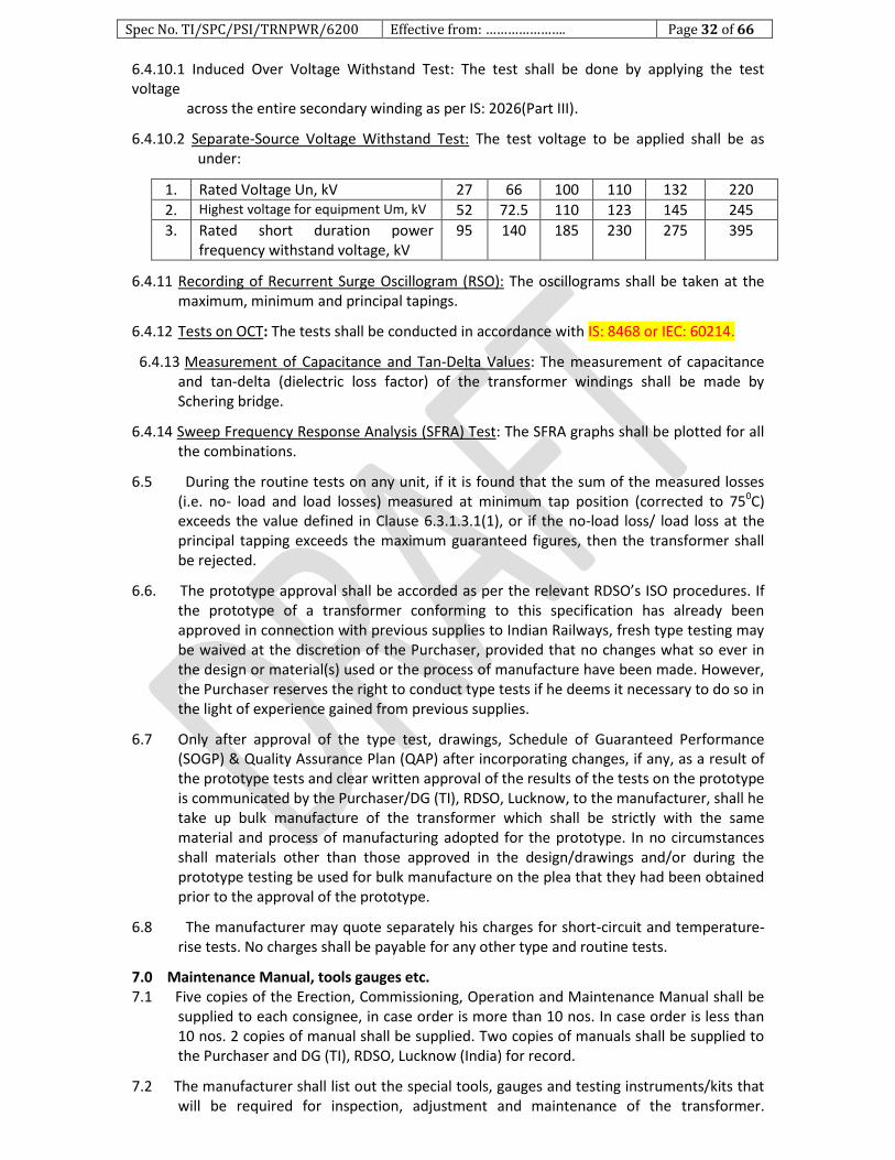
Spec No. TI/SPC/PSI/TRNPWR/6200 Effective from: …………………. Page 32 of 66
6.4.10.1 Induced Over Voltage Withstand Test: The test shall be done by applying the test voltage across the entire secondary winding as per IS: 2026(Part III).
6.4.10.2 Separate-Source Voltage Withstand Test: The test voltage to be applied shall be as under:
1. Rated Voltage Un, kV 27 66 100 110 132 220
2. Highest voltage for equipment Um, kV 52 72.5 110 123 145 245
3. Rated short duration power frequency withstand voltage, kV
95 140 185 230 275 395
6.4.11 Recording of Recurrent Surge Oscillogram (RSO): The oscillograms shall be taken at the maximum, minimum and principal tapings.
6.4.12 Tests on OCT: The tests shall be conducted in accordance with IS: 8468 or IEC: 60214.
6.4.13 Measurement of Capacitance and Tan-Delta Values: The measurement of capacitance and tan-delta (dielectric loss factor) of the transformer windings shall be made by Schering bridge.
6.4.14 Sweep Frequency Response Analysis (SFRA) Test: The SFRA graphs shall be plotted for all the combinations.
6.5 During the routine tests on any unit, if it is found that the sum of the measured losses (i.e. no- load and load losses) measured at minimum tap position (corrected to 750C) exceeds the value defined in Clause 6.3.1.3.1(1), or if the no-load loss/ load loss at the principal tapping exceeds the maximum guaranteed figures, then the transformer shall be rejected.
6.6. The prototype approval shall be accorded as per the relevant RDSO’s ISO procedures. If the prototype of a transformer conforming to this specification has already been approved in connection with previous supplies to Indian Railways, fresh type testing may be waived at the discretion of the Purchaser, provided that no changes what so ever in the design or material(s) used or the process of manufacture have been made. However, the Purchaser reserves the right to conduct type tests if he deems it necessary to do so in the light of experience gained from previous supplies.
6.7 Only after approval of the type test, drawings, Schedule of Guaranteed Performance (SOGP) & Quality Assurance Plan (QAP) after incorporating changes, if any, as a result of the prototype tests and clear written approval of the results of the tests on the prototype is communicated by the Purchaser/DG (TI), RDSO, Lucknow, to the manufacturer, shall he take up bulk manufacture of the transformer which shall be strictly with the same material and process of manufacturing adopted for the prototype. In no circumstances shall materials other than those approved in the design/drawings and/or during the prototype testing be used for bulk manufacture on the plea that they had been obtained prior to the approval of the prototype.
6.8 The manufacturer may quote separately his charges for short-circuit and temperature-rise tests. No charges shall be payable for any other type and routine tests.
7.0 Maintenance Manual, tools gauges etc. 7.1 Five copies of the Erection, Commissioning, Operation and Maintenance Manual shall be
supplied to each consignee, in case order is more than 10 nos. In case order is less than 10 nos. 2 copies of manual shall be supplied. Two copies of manuals shall be supplied to the Purchaser and DG (TI), RDSO, Lucknow (India) for record.
7.2 The manufacturer shall list out the special tools, gauges and testing instruments/kits that will be required for inspection, adjustment and maintenance of the transformer.
Spec No. TI/SPC/PSI/TRNPWR/6200 Effective from: …………………. Page 33 of 66
Individual prices for the items included in the above list shall also be furnished. The exact quantities of tools, gauges and testing instruments /kits to be procured initially shall be decided at the time of contract for the interrupters based on the above price list.
8.0 Training of Indian Railway’s personnel
The offer shall include the training of two personnel of the Indian Railways free of cost at the manufacturer’s works in India or abroad and at the maintenance depots/workshops on a Railway system or other public utility where transformers of similar/identical design are in operation. The total duration of training for each personnel shall be 2 weeks of which approximately one week will be at manufacturer’s works and one week on a Railway system or other public utility. If the country of manufacturer is not India, the cost of travel to that country and back will be borne by the Indian Railways. Other details shall be settled at the time of finalizing the contract/Purchase Order.
9.0 Packing, Delivery, Commissioning etc.
9.1 The transformer shall be transported depending upon the transport facilities available for the route i.e. by rail or truck or ship.
9.2 The transformer shall be dispatched with its core and windings along with the tap-changer assembly in the transformer tank filled with oil and the space above the oil filled with pure dry air or inert gas like nitrogen at a pressure slightly above atmospheric pressure. However, if there are limitations on account of weight, the tank shall be filled with nitrogen under pressure and the oil for the first filling shall be supplied separately in steel drums. In case the tank is filled with inert gas the temperature and pressure at the time of filling shall be marked conspicuously on the transformer.
9.3 All openings created on the tank by removal of any items shall be closed with suitable blanking plates. All the parts, fittings and accessories such as conservator tank, bushings, silica gel breather, radiator, Buchholz relay, temperature indicators and other items shall be packed / crated separately along with a packing list/check list in each crate containing the following particulars:
Crate No.
Description of item/ component in the crate
Approx. gross weight in kgf
Approx. outside dimensions in mm
All the matching parts shall be identical with the transformer Sl. No. or Work Order No. to avoid any mismatching at site.
9.4 The packing shall be done properly so that no damage occurs during transit.
9.5 All the parts, fittings and accessories for each transformer shall be so dispatched that they arrive at site together to enable erection of the complete without delay.
9.6 Necessary instructions for handling and storage of all items shall be included along with the packing lists.
9.7 In case of overseas supply, packing shall be sea worthy.
9.8 The transformer shall be erected and commissioned by the Purchaser. The successful tenderer/manufacturer shall invariably make available at site the services of an engineer of his to ensure, by his continued presence, that the process of erection, testing and commissioning of the transformer is in accordance with established practices. For this purpose prior intimation regarding the dates/period and locations at which the transformers are to be erected and testing / commissioning done shall be given by the Purchaser to the successful tenderer/manufacturer. No charges shall be payable by the

Spec No. TI/SPC/PSI/TRNPWR/6200 Effective from: …………………. Page 34 of 66
purchaser to the successful tenderer/manufacturer for the services of his engineer in this regard.
9.9 If any transformer has been received at site in a damaged condition and in the opinion of the Railway's Engineer at site it is required to be repaired at the successful tenderer/manufacturer's works, the transformer shall be taken back to the works promptly and after repair, all necessary tests including the routine tests shall be done on the complete transformer in the presence of and to the satisfaction of the Railway's Engineer prior to returning the transformer to site. Such tests are necessary to ensure that the quality of the workmanship during repairs is satisfactory and shall be done free of cost. Any tests, as decided by the Railway's Engineer at site shall also be conducted on the transformer at site free of cost.
10.0 Warranty
10.1 The manufacturer shall warrant that all equipments shall be free from defects and faults in design, material, workmanship, manufacture and are of the highest grade consistent with the established and generally accepted standards. The equipments are in full conformity with this specification and shall operate properly.
10.2 This warranty shall cover inspection of, payment for and acceptance of the equipment, but shall expire 30 (Thirty) months after the delivery at ultimate destination in India, or 24 (Twenty Four) months from the date of commissioning and proving test of the equipment at ultimate destination in India, whichever period expires earlier, except in respect of complaints, defects and/or claims notified to the successful tenderer/manufacturer within 3(Three) months of the expiry of such date. Any approval or acceptance by the Purchaser of the equipment shall not in any way limit the manufacturer’s liability.
10.3 The manufacturer’s liability in respect of any complaint, defects and/or claims shall not be limited to the furnishing and installation of replacement of parts free of any charge or the repair of defective parts only to the extent that such replacement or repairs are attributable to or arise from faulty workmanship or material or design in the manufacture of the goods, provided that the defects are brought to the notice of the manufacturer within 3(Three) months of their being first discovered during the warranty period of 3(Three) months from the date of expiry of warranty period, or at the option of the Purchaser, to the payment of the value, expenditure and damage as hereafter mentioned
10.4 The manufacturer shall, if required, replace or repair the equipment of such portion thereof as is rejected by the Purchaser free of cost at the ultimate destination or at the option of the Purchaser. Manufacturer shall pay to the Purchaser value thereof at the contract price or in the absence of such price at a price decided by the Purchaser and such other expenditure and damages as may arise by reason of the breach of the conditions herein specified.
10.5 All replacement and repairs that the Purchaser shall call upon the manufacturer to deliver or perform under this warranty shall be delivered and performed by the manufacturer, promptly and satisfactorily and in any case within 2(Two) months of the date of advice to this effect.
10.6 If the manufacturer so desires, the parts that are removed may be taken over by him or his representative for disposal as he deems fit at the time of replacement with good parts. No claim whatsoever shall lie on the Purchaser thereafter for the parts so removed.
10.7 The warranty herein contained shall not apply to any material which shall have been repaired or altered by the Purchaser or on his behalf in any way without the consent of the manufacturer, so as to affect the strength, performance or reliability or to any defects to any part due to misuse, negligence or accident.

Spec No. TI/SPC/PSI/TRNPWR/6200 Effective from: …………………. Page 35 of 66
10.8 The decision of the Purchaser in regard to successful tenderer/manufacturer’s liability and the amount, if any, payable under this warranty shall be final and conclusive.
11.0 Spares & after sales-service and AMC
11.1 The Tenderer shall quote separately for the following essential spares for every lot of up to 5 transformers or part thereof: 1. One set of primary coil, secondary coil and tapping coil. 2. One primary bushing complete with parts, fittings and bushing type current
transformer. 3. One secondary bushing complete with parts, fittings and bushing type current
transformer. 4. One complete set of gaskets of all sizes required for use in the transformer. 5. One breather unit with silica gel. 6. One set of radiator banks. 7. One Buchholz relay. 8. One complete off-circuit tap -changer. 9. One each of terminal connectors for primary and secondary side bushing terminals. 10. One set of valves. 11. One pressure relief device.
11.2 The manufacturer shall make necessary arrangements for closely monitoring the performance of the transformer through periodical (preferably once in two months during the warranty period) visit to the locations where they have been erected for observations and interactions with the operating and maintenance personnel of Indian Railways. Arrangements shall also be made by the manufacturer for emergency/standby spare parts being kept readily available to meet exigencies warranting replacement so as to keep the transformer in service with least down time.
11.3 The manufacturer shall respond promptly on any call given by Indian Railways for any assistance by way of attending to failures, investigations into the causes of failures including the tests, if any, to be done and such other items with a view to seeing that the transformer serves the purpose for which it is procured. Besides, technical guidance to ensure proper operation and maintenance of the transformer shall be constantly rendered.
12.0 Technical Data and Drawings to be furnished along with the tender
12.1 The manufacturer shall furnish the Technical and Other Particulars (SOGP) (Performa at Annexure-3) for the transformer in the along with his offer. The particulars shall be complete in all respects. If there is any entry like “shall be furnished later” or blank is left against any item, the offer is not likely to be considered as the evaluation of the offer is rendered difficult and cannot be computed with other offers, if any.
12.2 The manufacturer shall specifically indicate in a “Statement of Compliance” attached with the offer his compliance with each and every clause of the specification. In case the manufacturer wishes to deviate from any clause from this specification, he may wishes do so giving references to the clause(s) with the reasons/justifications for the deviation. This shall be in the form of a separate statement called the “Statement of Deviations. If there is no deviation at all, a specific “NIL” “Statement of Deviations” shall be attached with the offer. If the “Statement of Compliance” and “Statement of Deviations” are not attached with the offer, it is not likely to be considered for the reason that it is an incomplete offer which cannot be properly evaluated and compared with the other offers, if any.
12.3 The manufacturer shall furnish the following information along with his offer:
12.3.1 Calculations for:
Spec No. TI/SPC/PSI/TRNPWR/6200 Effective from: …………………. Page 36 of 66
1. Temperature rise of winding at rated current.
2. Hot-spot temperature of the winding at 150% and 200% rated loads for 15 min and 5 min respectively.
3. Thermal withstand capacity of the windings for a short circuit of 5 seconds duration.
4. Mechanical forces in respect of the following as per IEEMA (Indian Electrical & Electronic Manufacturer's Association) formulae given in Annexure-4.
1) Asymmetrical short-circuit current. 2) Hoop stress in primary and secondary windings. 3) Compressive pressure in the radial spacers. 4) Internal axial compressive force. 5) Axial imbalance force. 6) Radial bursting force. 7) Resistance to collapse. 8) Bending stress on clamping ring and densified wood. 9) Maximum allowable torque on pressure screws for coil clamping bolts
at the time of tightening, if any. 5. Flux density with the characteristic curve. 6. Maximum value of inrush current.
12.3.2 Drawings for:
i. Outline general arrangement drawing giving complete details of the transformer. ii. Arrangement of the core, windings and magnetic path.
iii. Magnetizing characteristic of CRGO sheet steel. iv. Drawing showing elevation of the core and winding and other insulation materials. v. A sectional view showing the position of core cylinders, winding blocks, vertical ribs
and other insulating materials. vi. Details of coil clamping arrangement.
vii. General arrangement of the off-circuit tap – changer.
12.3.3 Other Documents for i. Quality Assurance Plan for the Transformer
ii. ISO certification regarding quality system manufacturing, testing facilities, R&D facilities and reliability
iii. List of essential plant, machinery and testing facilities iv. Up-dated calibration certificate for the testing equipment v. Type test report for the relevant rating of the tendered transformer. vi. List of supplies & performance reports from the users for tendered transformer.
12.4 The manufacturer shall submit to DG(TI), RDSO, Lucknow for approval the following detailed dimensioned drawings as per Indian Railways standard in sizes of 210mm x 297mm or any integral multiples thereof:- 1. Outline general arrangement of the transformer indicating plan, front elevation, side
elevation with all parts, fittings and accessories, electrical clearances as well as salient guaranteed particulars.
2. Internal arrangement of the transformer indicating primary and secondary bushing lead connections, core to core- clamp earthing, core- clamp to tank earthing, core- clamp to core-base bolting, and the locking arrangement of the core & coil assembly with the tank.
3. Cross sectional view of the core and windings with material specifications and makes. 4. Details of the pressure screws / oil dash-pot/ coil clamping bolts or other devices and
their location with materials specifications and makes. 5. Schematic view of the valves used on the transformer and the antitheft devices as to
diagram.
Spec No. TI/SPC/PSI/TRNPWR/6200 Effective from: …………………. Page 37 of 66
6. Transport outline dimensional diagram. 7. General arrangement of the off-circuit tap-changer assembly with salient technical
parameters. 8. Tap-changer cubicle layout. 9. Schematic diagram for driving of motorized off-circuit ap-changer from remote
control centre by telecommand and corresponding telesignalling. 10. Name and rating plate of motorized off-circuit tap-changer. 11. General arrangement of marshaling box & RTCC indicating protection control
equipment. 12. Wring diagram of marshalling box. 13. Schematic diagram of protection and control circuits in marshalling box with cable
schedule. 14. Legend plate showing protection and control circuits for fitment in the marshalling
box. 15. OIP Condenser Bushing for primary side including cross-sectional view, shed profile
and salient electrical and mechanical characteristics. 16. OIP condenser bushing for secondary side including cross-sectional view shed profile
and salient electrical and mechanical characteristics. 17. Dimensional drawing, V-I characteristic and rating plate for bushing types current
transformers. 18. Rigid type terminal connector for primary side bushing terminal. 19. Expansion type terminal connector for secondary side bushing terminal. 20. Rating plate diagram of connections, both in English and Hindi versions. 21. Details of radiators. 22. Details of breather. 23. External cables run with cable schedule. 24. Any other drawings considered necessary by the manufacture and/ or purchaser.
12.4.2 After approval, six copies of each of the approved drawings shall be supplied to each consignee(s). Besides, after final approval, one copy of drawings in hard as well as in soft shall be submitted to DG, RDSO, Lucknow.
13.0 Clause wise conformity, deviations etc. 13.1 The manufacturer shall specifically indicate in a statement attached with his offer, his
compliance with each clause and sub-clause of this specification. A separate statement shall be attached with the offer indicating references to the clauses where the tenderer deviate there from together with detailed remarks/justification. If there are no deviations, a ‘NIL’ statement shall be attached.
13.2 Any deviation from this specification which the tenderer proposes to improve upon the performance, utility and efficiency of the equipment will be given due consideration, provided full particulars of the deviation with justification thereof are furnished, and are found acceptable by RDSO.
14.0 CAPITALISATION OF TRANSFORMER LOSSES The capitalized valve of transformer losses shall be as low as possible and commensurate
with optimum no-load and load the losses. The capitalized value shall be computed as detailed at Annexure -5 and furnished with offer. Capitalized value calculated, as per Annexure-5 shall be added to the unit cost of the transformer for taking into consideration the cost of losses during its service life.
Spec No. TI/SPC/PSI/TRNPWR/6200 Effective from: …………………. Page 38 of 66
Annexure-1
Technical Specifications for Nitrogen Injection Fire Prevention and Extinguishing System (NIFPES) for Oil Filled Transformer.
1.0 SCOPE: The scope of this specification covers design, manufacturing, engineering, supply, testing at works before dispatch; erection, testing and commissioning and performance demonstration of “Fire prevention and extinguishing system by nitrogen injection method”. The necessary civil work which will be required for construction of oil soak pit for the storage of oil coming out from the transformer and plinth for Fire Extinguishing Cubicle (FEC) is outside the scope of this specification. However, laying of oil pipe, nitrogen pipe, electrical cables, control boxes, extinguishing cubicle, nitrogen cylinder, necessary valves, fire detectors and other equipments & accessories required for erection, testing, commissioning and performance demonstration of the complete fire protection system is in the scope of the NIFPES manufacturer. It will be the responsibility of the transformer manufacturer to coordinate with the supplier of the Fire Protection System for all the arrangements for the complete erection, testing, commissioning and performance tests.
2.0 GENERAL DESCRIPTION:
2.1 Nitrogen Injection system shall be used to prevent the transformer explosion and possible fire, in the case of internal fault and such acts as a fire preventer. In certain cases, tank explosion cannot be prevented and transformer oil catches fire. In such cases and also in the event of fire by external causes, it shall acts as fire fighting system. In either way it shall protect the transformer and eliminate or minimize the post fire damages. Thus, the system shall be suitable for protecting the transformer tank from explosion and also transformer, OCTC and cable box from fire.
2.2 The system shall drain a pre-determined quantity (at least 10% by volume) of the of oil from the tank top through outlet valve to reduce the tank pressure and inject nitrogen gas at predetermined pressure from the lower side of the tank through inlet valves to create stirring action and reduce the temperature of top oil surface below flash point to extinguish the fire.
2.3 The system shall consist of following major components: a) Fire Extinguishing Cubicle (FEC) placed on a plinth at about 5-10 meter away from the
transformer. b) Control box placed in the control room. c) Transformer Conservator Isolation valve (TCIV) in the conservator pipe. d) Fire Detectors to be provided on the tank cover. e) Signal box fitted on the transformer tank side wall.
3.0 Details of Major System components: 3.1 Fire Extinguishing Cubicle (FEC): Fire Extinguishing Cubicle shall have the following:
3.1.1 Nitrogen gas cylinder with pressure reducer or pressure regulator. Necessary gauges shall be provided to monitor the nitrogen cylinder pressure as well as nitrogen injection pressure. Also, provision shall be provided for indication in the control box if the cylinder pressure reduced than specified pressure. Pressure reducer or pressure regulator and gauges used shall have IP-65 protection.
3.1.2 The nitrogen gas cylinder should contain 10 cubic meter gas at pressure of 150kg/cm2
up to 60,000 liters oil capacity of transformer. 3.1.3 The nitrogen shall be contained within the cylinder and released from the cylinder
valve only upon activation of fire protection system. No used bottle should be accepted. Proper approvals and certificates should be provided with each cylinder. NIFPES manufacturer to ensure to provide the cylinders having the PESO (Petroleum and Explosive safety Organisation) certificates. Nitrogen purity shall be 99.99%.
Spec No. TI/SPC/PSI/TRNPWR/6200 Effective from: …………………. Page 39 of 66
3.1.4 Pressure monitoring switch for back-up protection for nitrogen release as redundancy to first signal of oil draining commencement for Nitrogen release shall preferably be provided.
3.1.5 Oil drain pipe with mechanical quick drain valve. 3.1.6 Electro mechanical control equipments for oil drain and pre- determined regulated
nitrogen release. 3.1.7 Limit switches for monitoring of the system.
3.1.8 Isolation valves for oil drain and nitrogen injection pipe with necessary flanges shall be provided on top of the Fire Extinguishing Cubicle (FEC) for connecting oil drain and nitrogen injection pipes with transformer.
3.1.9 Fire Extinguishing Cubicle (FEC) shall have LED light and heater with thermostat. FEC should have IP 55 protection.
3.1.10 Oil drain pipe extension of suitable sizes for connecting pipes to oil pit. 3.1.11 Individual mechanical locking arrangement for nitrogen release as well as oil drain to
avoid unnecessary operation during maintenance and/or testing of transformer and /or system.
3.2 Control box: Control Box shall have the following provisions: 3.2.1 Control Box should be microprocessor based compatible to be interfaced with
existing RTU for Railway Traction SCADA system. For communication with SCADA, Control Box shall have provision for interfacing with RTU through RS485 over MODBUS protocol. Following indications of NIFPES are to be interfaced with SCADA: NIFPES active in prevention mode. NIFPES active in extinguishing mode. Status of NIFPES i.e. in Auto/Manual/OFF position. NIFPES system is healthy
3.2.2 Control box shall have activating, monitoring devices and line faults indicators. It should have audio visual alarm indication and push button switches for test response.
3.2.3 Following minimum indications (LED type) shall be provided on the Control Box.
SN Indication Colour SN Indication Colour
a) System On Green b) LV Circuit Breaker Open RED
c) Oil Drain Valve Closed Green d) HV Circuit Breaker Open RED
e) Nitrogen Injection Valve Closed Green f) Differential Relay Trip RED
g) System Healthy Green h) Restricted Earth fault Relay Trip RED
i) TCIV Open Green j) Overcurrent Relay Trip RED
k) System out of Service RED l) Bucholz Relay trip RED
m) TCIV Closed RED n) Pressure Relief Valve Trip RED
o) Oil Drain valve open RED p) Fire Detector Trip RED
q) Extinction in progress RED r) DC supply fail RED
s) Nitrogen Cylinder Pressure Low RED t) AC Supply fail RED
u) Auto operation failed RED
3.2.4 Other provisions on the Control Box.
SN Description
a. Push Button for lamp test
b. Mode Selection Switch, Auto/Manual/OFF
c. Extinction Release (manual operation) Push Button
d. Audio Alarm
3.3 Transformer Conservator Isolation valve (TCIV): TCIV to be fitted in the conservator pipe line, between conservator and buchholz relay to block oil passage to isolate conservator tank oil. Thus, prevent escalation of fire at the time of the activation of NIFPES. It shall also
Spec No. TI/SPC/PSI/TRNPWR/6200 Effective from: …………………. Page 40 of 66
have electrical signal for monitoring the status and a transparent window for visual inspection of the status of valve.
3.4 Fire Detectors: Fire detectors shall be specially designed to generate an electrical signal to the NIFPES system after sensing higher temperature. Fire detectors are to be fixed on transformer tank top cover and Off Circuit Tap Changer tap change for sensing fire.
3.5 Signal box: Signal Box shall be provided for terminating cable connections from fire detectors and TCIV.
3.6 Signal Box, Control Box & FEC should be vermin proof and cable glands (as required) shall be provided for terminating cables.
4.0 OPERATIONAL CONTROLS: Following mode of control shall be provided for the activation of NIFPES.
4.1 Automatic control in fire prevention and fire extinction modes after receipt of the system activating signals.
4.2 An electrical push button on control box for activating the NIFPES. This push button should be covered under glass to avoid false pressing.
4.3 An electrical push button in the Fire Extinguishing Cubicle (FEC) for activating the NIFPES.
4.4 Manual operation form Fire Extinguishing Cubicle (FEC) in case of DC supply fails.
5.0 SYSTEM ACTIVATING SIGNALS:
5.1 Transformer isolation shall be an essential pre-condition for activating the system. 5.2 In activation of auto mode, NIFPES system should also give a command to isolate the
Traction Power Transformer through Master trip relay or circuit breaker (HV and LV side in series) before oil depressurization and nitrogen injection.
5.3 System operation in auto mode: In auto mode, there shall be two modes of operation of Fire protection system i.e. Fire prevention mode and Fire Extinction Mode. The inputs to be used for the activation of the system are as below:
Mode of operation
Inputs to be used for activation of NIFPES:
Fire Prevention Mode
For activation in Prevention Mode any one of the following two options shall be accepted:
Option 1
Signals from both HV and LV Circuit Breakers for open condition
Differential Relay OR Over Current Relay OR Restricted Earth fault relay.
Buchholz Relay OR Pressure relief valve.
Description: The NIFPES should be activated only after the receipt of both HV & LV circuit Breaker open signals AND signal for activation of any one or more of the three i.e. Differential, Over Current , Restricted Earth fault relay AND signal for activation of any one or more of the Buchholz Relay, pressure relief valve.
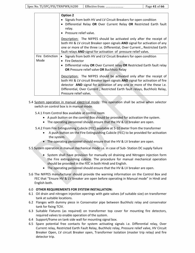
Spec No. TI/SPC/PSI/TRNPWR/6200 Effective from: …………………. Page 41 of 66
Option 2
Signals from both HV and LV Circuit Breakers for open condition
Differential Relay OR Over Current Relay OR Restricted Earth fault relay.
Pressure relief valve.
Description: The NIFPES should be activated only after the receipt of both HV & LV circuit Breaker open signals AND signal for activation of any one or more of the three i.e. Differential, Over Current , Restricted Earth fault relays AND signal for activation of pressure relief valve.
Fire Extinction Mode
Signals from both HV and LV Circuit Breakers for open condition
Fire Detector
Differential relay OR Over Current relay OR Restricted Earth fault relay OR Pressure relief valve OR Buchholz Relay
Description: The NIFPES should be activated only after the receipt of both HV & LV circuit Breaker open signals AND signal for activation of fire detector AND signal for activation of any one or more of the these i.e. Differential, Over Current , Restricted Earth fault relays, Buchholz Relay, Pressure relief valve.
5.4 System operation in manual electrical mode: This operation shall be active when selector
switch on control box is in manual mode.
5.4.1 From Control Box available at control room
A push button on the control Box should be provided for activation the system.
The operating personnel should ensure that the HV & LV breaker are open.
5.4.2 From Fire Extinguishing Cubicle (FEC) available at 5-10 meter from the transformer
A push button on the Fire Extinguishing Cubicle (FEC) to be provided for activation the system.
The operating personnel should ensure that the HV & LV breaker are open.
5.5 System operation in manual mechanical mode i.e. in case of Sub- Station DC supply failure
System shall have provision for manually oil draining and Nitrogen injection form the Fire extinguishing cubicle. The procedure for manual mechanical operation should be provided in the FEC in both Hindi and English.
The operating personnel should ensure that the HV & LV breaker are open.
5.6 The NIFPES manufacturer should provide the warning information on the Control Box and FEC that “Ensure HV & LV breaker are open before operating in Manual mode” in Hindi and English both.
6.0 OTHER REQUIREMENTS FOR SYSTEM INSTALLATION: 6.1 Oil drain and nitrogen injection openings with gate valves (of suitable size) on transformer
tank at suitable locations. 6.2 Flanges with dummy piece in Conservator pipe between Buchholz relay and conservator
tank for fixing TCIV. 6.3 Suitable Fixtures (as required) on transformer top cover for mounting fire detectors,
required valves to enable operation of the system. 6.4 Support/frame on tank side wall for mounting signal box. 6.5 Spare potential free contacts for system activating signals i.e. Differential relay, Over
Current relay, Restricted Earth Fault Relay, Buchholz relay, Pressure relief valve, HV Circuit Breaker Open, LV circuit Breaker open, Transformer Isolation (master trip relay) and fire detector trip.

Spec No. TI/SPC/PSI/TRNPWR/6200 Effective from: …………………. Page 42 of 66
6.6 Pipe connections between transformer to Fire Extinguishing Cubicle (FEC) and Fire Extinguishing Cubicle to oil pit. The pipes shall be of galvanized iron material.
6.7 Cabling on transformer top cover for fire detectors, interconnection cabling between Signal box to Control Box and Control Box to Fire Extinguishing cubicle. The cabling should be suitably done for proper functioning of the system.
6.8 In order to place the fire Extinguishing Cubicle, plinth shall be constructed as per the drawing provided by the manufacturer.
6.9 In order to collect the drained oil upon activation of the system, oil-pit should be constructed with a capacity of not less than 10% of the total transformer oil volume. To achieve speedy drain of oil, the oil drain piping should have minimum bend and shall be directly terminated in to oil drain pit.
6.10 All other consumables necessary for operation of complete system.
7.0 DATA SHEET:
SN Item Requirements
1. Fire Extinction period on commencement of Nitrogen injection
Maximum 30 seconds
2. Fire detectors heat sensing temperature
130 ± 20 C
3. Heat sensing area 800 mm radius
4. Power Source: Control Box. Fire extinguishing cubicle for lighting and heater
110 V DC (+10% & -15%) 240 V AC
5. Nitrogen Cylinder As per IS:7285 (Part – 2)
6. Capacity of Nitrogen Cylinder 10m3 gas
7. Pressure of Nitrogen filling 150kg/cm2
8. Oil Drain gate valve Size : 80 mm, 01 No.
9. Nitrogen injection valve Size: 25mm, 04numbers, 02 each on HV & LV side
10. Colour of cubicles & Nitrogen Injection pipes
Shade 538 of IS: 5
11. Degree of protection of FEC IP 55
12. Sheet of FEC, Control Box & Signal Box Steel sheet of thickness not less than 2mm
8.0 Cabling: 8.1 Fire survival cables, able to withstand 750 0C, 1.5 mm sq. with necessary no. of Conductors
for connection of fire detectors in parallel shall be used (if applicable). The test certificates for the cables shall be submitted.
8.2 Fire retardant low smoke (FRLS) cable 1.5 mm sq. with necessary no. of Conductors for connection between transformer signal box/ marshaling box to control box and control box to fire extinguishing cubicle shall be used.
8.3 Fire retardant low smoke (FRLS) 1.5 mm sq. with necessary no. of Conductors for connection between Control and Relay panel to Control Box, Control box to DC supply source, Control box to AC supply source and fire extinguishing cubicle to AC supply source, signal box /marshaling box on transformer shall be used.
9.0 PREVIOUS EXPERIENCE FOR QUALIFYING SUPPLIER:
The supplier shall have a minimum experience of two years in the design, manufacturing, erection, testing and commissioning of nitrogen injection fire prevention and extinguishing system on power transformers of 21.6MVA or higher MVA. At least 2 sets of the system
Spec No. TI/SPC/PSI/TRNPWR/6200 Effective from: …………………. Page 43 of 66
shall be in successful operation for a minimum period of the 2 years in order to meet the criteria. The supplier shall furnish the details of NIFPES supplied by them so far, giving order reference, name and address of the customer, indicating the dates of commissioning as well as performance certificate of successful and satisfactory operation for minimum two years from the customers.
10.0 TESTS 10.1 TYPE TESTS
10.1.1 Type test report of the NIFPES system: Type test report of the NIFPES system shall be submitted to RDSO along with the design/drawing documents. The system shall be tested by a NABL accredited recognized laboratory. Type test report submitted shall have used the input required for the operation of NIFPES as in RDSO specification. The fire extinction period mentioned in the report shall meet the requirements of this specification.
10.1.2 Type test report of Fire detector: Type test report of the Fire Detector shall be submitted
to RDSO along with the design/drawing documents. The Fire detector shall be tested by a NABL accredited recognized laboratory. The heat sensing temperature and area mentioned in the report shall meet the requirements of this specification.
10.2 FACTORY TEST The factory test of the NIFPES at the works of NIFPES manufacturer shall be conducted as per the format mentioned at Para 13.0 of NIFPES specification.
10.3 PERFORMANCE TEST Performance test of the complete system shall be carried out after complete erection at site by the supplier’s representative. These tests shall include simulation and verification of the response the complete system without actual draining of the oil and injection of the nitrogen gas. In addition to above, additional tests as required necessary shall be conducted.
11.0 DRAWINGS AND MANUALS 11.1 Detailed layout drawing along with the equipment drawings to be given in the tender along
with complete bill of materials. After awarding of contract, detailed dimensional drawing of the system complete bill of materials including location and size of plinth for cubicle and recommended capacity of oil soak- pit shall be submitted for purchaser’s approval. After approval 10 (ten) sets of all above drawings and 5 (five) sets of operation and maintenance instruction manual shall be submitted for purchaser’s use.
11.2 Following test certificates/details shall also be submitted during the approval of drawings of NIFPES.
i. Type, make, and quantity of Fire Sensing Component being used with Railway Transformer.
ii. IP-65 protection certificate of the pressure reducer or pressure regulator and pressure gauges provided in the FEC.
iii. IP-55 protection certificate of Fire Extinguishing Cubicle (FEC). iv. Type, make and quantity of the fire survival cable and test report of the cable
reflecting withstand temperature (if applicable). v. Type and make of the FRLS cable of 1.5mm sq. along with Cable Manufacturer’s
Test Certificate. vi. Type test reports as mentioned in the Para 10.1.1 & 10.1.2.
vii. Experience certificates as mentioned in Para 9.0. viii. The copy of Manual of NIFPES.
ix. The purity certificate of Nitrogen of 99.99% purity for each cylinder.
12.0 SPARES:
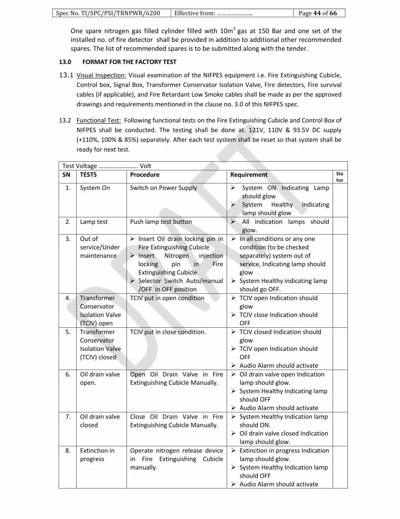
Spec No. TI/SPC/PSI/TRNPWR/6200 Effective from: …………………. Page 44 of 66
One spare nitrogen gas filled cylinder filled with 10m3 gas at 150 Bar and one set of the installed no. of fire detector shall be provided in addition to additional other recommended spares. The list of recommended spares is to be submitted along with the tender.
13.0 FORMAT FOR THE FACTORY TEST
13.1 Visual Inspection: Visual examination of the NIFPES equipment i.e. Fire Extinguishing Cubicle,
Control box, Signal Box, Transformer Conservator Isolation Valve, Fire detectors, Fire survival
cables (if applicable), and Fire Retardant Low Smoke cables shall be made as per the approved
drawings and requirements mentioned in the clause no. 3.0 of this NIFPES spec.
13.2 Functional Test: Following functional tests on the Fire Extinguishing Cubicle and Control Box of
NIFPES shall be conducted. The testing shall be done at. 121V, 110V & 93.5V DC supply
(+110%, 100% & 85%) separately. After each test system shall be reset so that system shall be
ready for next test.
Test Voltage ……………………. Volt
SN TESTS Procedure Requirement Status
1. System On Switch on Power Supply System ON Indicating Lamp should glow
System Healthy Indicating lamp should glow
2. Lamp test Push lamp test button All indication lamps should glow.
3. Out of service/Under maintenance
Insert Oil drain locking pin in Fire Extinguishing Cubicle
Insert Nitrogen injection locking pin in Fire Extinguishing Cubicle
Selector Switch Auto/manual /OFF in OFF position
In all conditions or any one condition (to be checked separately) system out of service, Indicating lamp should glow
System Healthy indicating lamp should go OFF.
4. Transformer Conservator Isolation Valve (TCIV) open
TCIV put in open condition TCIV open Indication should glow
TCIV close Indication should OFF
5. Transformer Conservator Isolation Valve (TCIV) closed
TCIV put in close condition. TCIV closed Indication should glow
TCIV open Indication should OFF
Audio Alarm should activate
6. Oil drain valve open.
Open Oil Drain Valve in Fire Extinguishing Cubicle Manually.
Oil drain valve open Indication lamp should glow.
System Healthy Indicating lamp should OFF
Audio Alarm should activate
7. Oil drain valve closed
Close Oil Drain Valve in Fire Extinguishing Cubicle Manually.
System Healthy Indication lamp should ON.
Oil drain valve closed Indication lamp should glow.
8. Extinction in progress
Operate nitrogen release device in Fire Extinguishing Cubicle manually.
Extinction in progress Indication lamp should glow.
System Healthy Indication lamp should OFF
Audio Alarm should activate

Spec No. TI/SPC/PSI/TRNPWR/6200 Effective from: …………………. Page 45 of 66
9. Nitrogen Injection valve closed
Close nitrogen release device in Fire Extinguishing Cubicle manually
System Healthy Indication lamp should ON
Nitrogen Injection valve closed Indicating lamp should glow.
10. Nitrogen Gas Cylinder pressure low
Adjust manometer below the specified pressure.
Cylinder pressure low Indication lamp should glow.
System Healthy Indication lamp should OFF
Audio Alarm should activate
11. Differential relay trip
Activate the signal at potential free contact of Differential Relay trip on terminal bar
Differential Relay trip Indicating lamp should glow.
System Healthy Indication lamp should OFF
Audio Alarm should activate
Deactivate the signal. Healthy condition Indication lamp should turn ON
Differential Relay trip Indicating lamp should go OFF.
12. Over Current Relay (OCR) Trip
Activate the signal at potential free contact of OCR trip on terminal bar
OCR trip Indicating lamp should glow.
System Healthy Indication lamp should OFF
Audio Alarm should activate
Deactivate the signal. System Healthy Indication lamp should turn ON
OCR Relay trip Indicating lamp should go OFF.
13. Restricted Earth Fault (REF) relay trip
Activate the signal at potential free contact of REF trip on terminal bar
REF trip Indicating lamp should glow.
System Healthy Indication lamp should OFF
Audio Alarm should activate
Deactivate the signal. System Healthy Indication lamp should turn ON
REF Relay trip Indicating lamp should go OFF.
14. Pressure Relief valve (PRV) Trip
Activate the signal at potential free contact of PRV trip on terminal bar
PRV trip Indicating lamp should glow.
System Healthy Indication lamp should OFF
Audio Alarm should activate
Deactivate the signal. System Healthy Indication lamp should turn ON
PRV trip Indicating lamp should go OFF.
15. Bucholz Relay Trip
Activate the signal at potential free contact of Bucholz Relay trip on terminal bar
Bucholz Relay trip Indicating lamp should glow.
System Healthy Indication lamp should OFF
Audio Alarm should activate
Deactivate the signal. System Healthy Indication lamp should turn ON
Bucholz Relay trip Indicating lamp should go OFF.
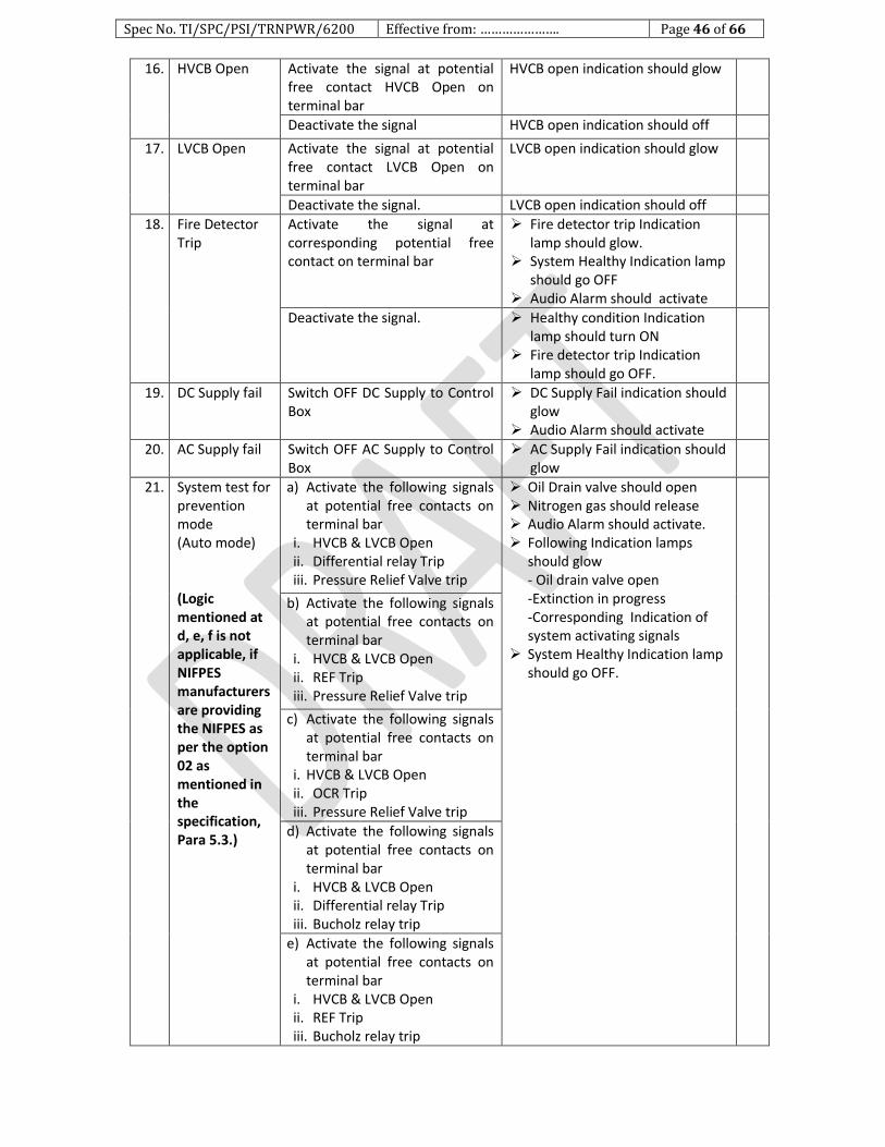
Spec No. TI/SPC/PSI/TRNPWR/6200 Effective from: …………………. Page 46 of 66
16. HVCB Open Activate the signal at potential free contact HVCB Open on terminal bar
HVCB open indication should glow
Deactivate the signal HVCB open indication should off
17. LVCB Open Activate the signal at potential free contact LVCB Open on terminal bar
LVCB open indication should glow
Deactivate the signal. LVCB open indication should off
18. Fire Detector Trip
Activate the signal at corresponding potential free contact on terminal bar
Fire detector trip Indication lamp should glow.
System Healthy Indication lamp should go OFF
Audio Alarm should activate
Deactivate the signal. Healthy condition Indication lamp should turn ON
Fire detector trip Indication lamp should go OFF.
19. DC Supply fail Switch OFF DC Supply to Control Box
DC Supply Fail indication should glow
Audio Alarm should activate
20. AC Supply fail Switch OFF AC Supply to Control Box
AC Supply Fail indication should glow
21. System test for prevention mode (Auto mode) (Logic mentioned at d, e, f is not applicable, if NIFPES manufacturers are providing the NIFPES as per the option 02 as mentioned in the specification, Para 5.3.)
a) Activate the following signals at potential free contacts on terminal bar
i. HVCB & LVCB Open ii. Differential relay Trip iii. Pressure Relief Valve trip
Oil Drain valve should open Nitrogen gas should release Audio Alarm should activate. Following Indication lamps
should glow - Oil drain valve open -Extinction in progress -Corresponding Indication of system activating signals
System Healthy Indication lamp should go OFF.
b) Activate the following signals at potential free contacts on terminal bar
i. HVCB & LVCB Open ii. REF Trip iii. Pressure Relief Valve trip
c) Activate the following signals at potential free contacts on terminal bar
i. HVCB & LVCB Open ii. OCR Trip iii. Pressure Relief Valve trip
d) Activate the following signals at potential free contacts on terminal bar
i. HVCB & LVCB Open ii. Differential relay Trip iii. Bucholz relay trip
e) Activate the following signals at potential free contacts on terminal bar
i. HVCB & LVCB Open ii. REF Trip iii. Bucholz relay trip
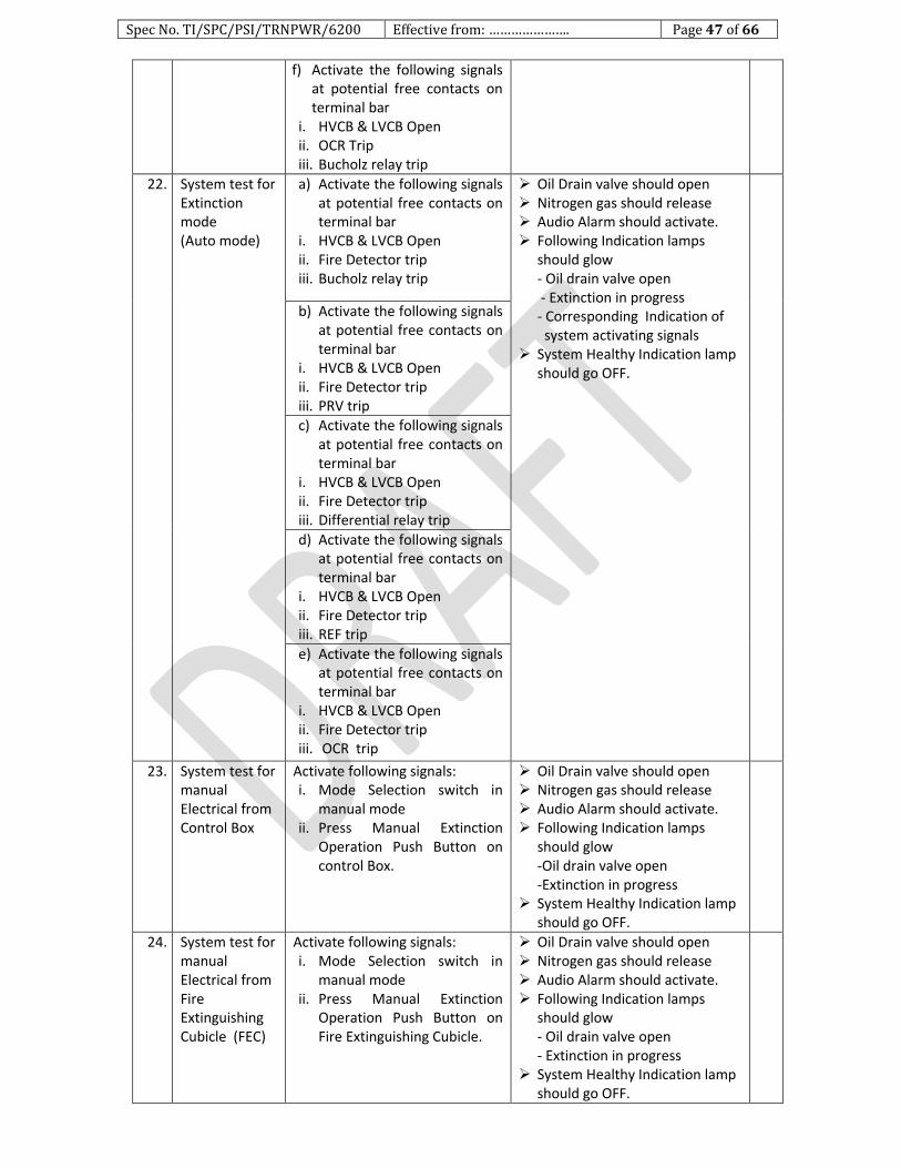
Spec No. TI/SPC/PSI/TRNPWR/6200 Effective from: …………………. Page 47 of 66
f) Activate the following signals at potential free contacts on terminal bar
i. HVCB & LVCB Open ii. OCR Trip iii. Bucholz relay trip
22. System test for Extinction mode (Auto mode)
a) Activate the following signals at potential free contacts on terminal bar
i. HVCB & LVCB Open ii. Fire Detector trip iii. Bucholz relay trip
Oil Drain valve should open Nitrogen gas should release Audio Alarm should activate. Following Indication lamps
should glow - Oil drain valve open - Extinction in progress - Corresponding Indication of system activating signals
System Healthy Indication lamp should go OFF.
b) Activate the following signals at potential free contacts on terminal bar
i. HVCB & LVCB Open ii. Fire Detector trip iii. PRV trip
c) Activate the following signals at potential free contacts on terminal bar
i. HVCB & LVCB Open ii. Fire Detector trip iii. Differential relay trip
d) Activate the following signals at potential free contacts on terminal bar
i. HVCB & LVCB Open ii. Fire Detector trip iii. REF trip
e) Activate the following signals at potential free contacts on terminal bar
i. HVCB & LVCB Open ii. Fire Detector trip iii. OCR trip
23. System test for manual Electrical from Control Box
Activate following signals: i. Mode Selection switch in
manual mode ii. Press Manual Extinction
Operation Push Button on control Box.
Oil Drain valve should open Nitrogen gas should release Audio Alarm should activate. Following Indication lamps
should glow -Oil drain valve open -Extinction in progress
System Healthy Indication lamp should go OFF.
24. System test for manual Electrical from Fire Extinguishing Cubicle (FEC)
Activate following signals: i. Mode Selection switch in
manual mode ii. Press Manual Extinction
Operation Push Button on Fire Extinguishing Cubicle.
Oil Drain valve should open Nitrogen gas should release Audio Alarm should activate. Following Indication lamps
should glow - Oil drain valve open - Extinction in progress
System Healthy Indication lamp should go OFF.

Spec No. TI/SPC/PSI/TRNPWR/6200 Effective from: …………………. Page 48 of 66
25. System test for Extinction mode Manual mechanical (To be used in case of d.c. supply failure)
To be done on Fire Extinguishing Cubicle i. Push lever for Oil drain. ii. Push Lever for Nitrogen gas
release.
Oil Drain valve should open Nitrogen gas should release
26. Panel Lighting Switch on 240V AC supply in fire extinguishing cubicle
Open Door of fire extinguishing cubicle
Panel Lights should be in working condition when door is open
27. Heater operation
Switch on the heater in Fire extinguishing cubicle
Heater should be in working condition
28. High voltage test to be separately done on Control Box and Signal Box
Apply 2kV AC for 1 minute between terminal bar and Box body
Should withstand.
29. Communication with SCADA
Control Box shall have provision for interfacing with RTU through RS485 over MODBUS protocol
The NIFPES manufacturer should verify the MODBUS protocol at their works or submit a declaration by an RDSO approved SCADA vendor that, the NIFPES system has been verified by them for communication with RTU through RS485 over MODBUS protocol
13.3 Functional Test of Transformer Isolation Conservator Valve (TCIV):
SN Test Procedure Requirement
1. Leakage Test Immerse the TCIV in the oil and fill the inlet pressure as 4 kg/ cm2 for 6 hours.
There should no leakage from TCIV body
2. TCIV Close test i. Mount TCIV with approx. 3 degree inclination on test jig
ii. Switch ON oil Pump iii. Increase oil flow rate
gradually
TCIV should close at flow rate specified by manufacturer.
Flap closing shall be visible through transparent glass inspection window.
Normally open (NO) contacts should close
3. Reset test Reset the TCIV handle in the normal position.
Close contact should become open
Flap opening shall be visible through transparent glass inspection window.
4. High voltage test
Apply 2kV AC for 1 minute between terminals and body
TCIV should withstand.
13.4 Functional Tests of Fire detector:
13.4.1 The test report of the fire detector shall be submitted. The test report shall be of NABL accredited recognized laboratory. The operating temperature and the heat sensing area mention in the report shall be as per the requirement mentioned in this specification.
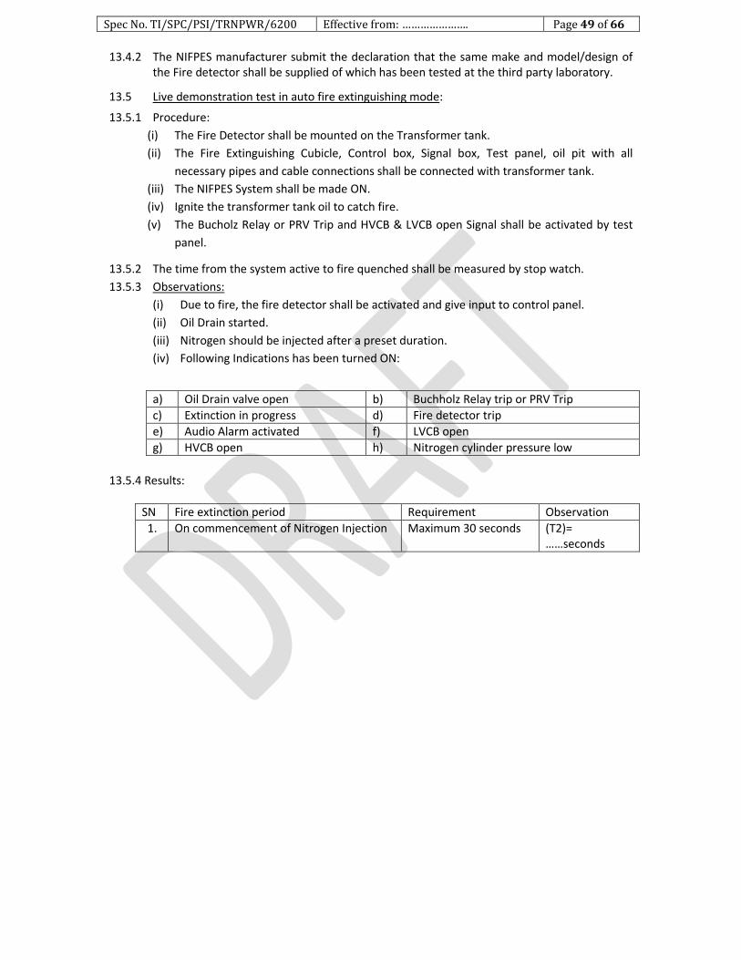
Spec No. TI/SPC/PSI/TRNPWR/6200 Effective from: …………………. Page 49 of 66
13.4.2 The NIFPES manufacturer submit the declaration that the same make and model/design of the Fire detector shall be supplied of which has been tested at the third party laboratory.
13.5 Live demonstration test in auto fire extinguishing mode:
13.5.1 Procedure:
(i) The Fire Detector shall be mounted on the Transformer tank.
(ii) The Fire Extinguishing Cubicle, Control box, Signal box, Test panel, oil pit with all
necessary pipes and cable connections shall be connected with transformer tank.
(iii) The NIFPES System shall be made ON.
(iv) Ignite the transformer tank oil to catch fire.
(v) The Bucholz Relay or PRV Trip and HVCB & LVCB open Signal shall be activated by test
panel.
13.5.2 The time from the system active to fire quenched shall be measured by stop watch.
13.5.3 Observations:
(i) Due to fire, the fire detector shall be activated and give input to control panel.
(ii) Oil Drain started.
(iii) Nitrogen should be injected after a preset duration.
(iv) Following Indications has been turned ON:
a) Oil Drain valve open b) Buchholz Relay trip or PRV Trip
c) Extinction in progress d) Fire detector trip
e) Audio Alarm activated f) LVCB open
g) HVCB open h) Nitrogen cylinder pressure low
13.5.4 Results:
SN Fire extinction period Requirement Observation
1. On commencement of Nitrogen Injection Maximum 30 seconds (T2)= ……seconds
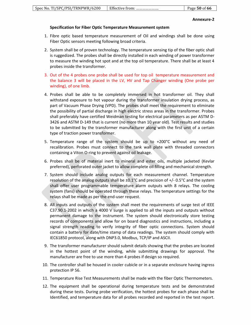
Spec No. TI/SPC/PSI/TRNPWR/6200 Effective from: …………………. Page 50 of 66
Annexure-2
Specification for Fiber Optic Temperature Measurement system
1. Fibre optic based temperature measurement of Oil and windings shall be done using Fiber Optic sensors meeting following broad criteria.
2. System shall be of proven technology. The temperature sensing tip of the fiber optic shall is ruggedized. The probes shall be directly installed in each winding of power transformer to measure the winding hot spot and at the top oil temperature. There shall be at least 4 probes inside the transformer.
3. Out of the 4 probes one probe shall be used for top oil temperature measurement and the balance 3 will be placed in the LV, HV and Tap Changer winding (One probe per winding), of one limb.
4. Probes shall be able to be completely immersed in hot transformer oil. They shall withstand exposure to hot vapour during the transformer insulation drying process, as part of Vacuum Phase Drying (VPD). The probes shall meet the requirement to eliminate the possibility of partial discharge in high electric stress areas in the transformer. Probes shall preferably have certified Weidman testing for electrical parameters as per ASTM D-3426 and ASTM D-149 that is current (no more than 10 year old). Test results and studies to be submitted by the transformer manufacturer along with the first unit of a certain type of traction power transformer.
5. Temperature range of the system should be up to +200°C without any need of recalibration. Probes must connect to the tank wall plate with threaded connectors containing a Viton O-ring to prevent against oil leakage.
6. Probes shall be of material inert to mineral and ester oils, multiple jacketed (Kevlar preferred), perforated outer jacket to allow complete oil filling and mechanical strength.
7. System should include analog outputs for each measurement channel. Temperature resolution of the analog outputs shall be ±0.1°C and precision of +/- 0.5°C and the system shall offer user programmable temperature alarm outputs with 8 relays. The cooling system (fans) should be operated through these relays. The temperature settings for the relays shall be made as per the end-user request.
8. All inputs and outputs of the system shall meet the requirements of surge test of IEEE C37.90.1-2002 in which a 4000 V surge is applied to all the inputs and outputs without permanent damage to the instrument. The system should electronically store testing records of components and allow for on board diagnostics and instructions, including a signal strength reading to verify integrity of fiber optic connections. System should contain a battery for date/time stamp of data readings. The system should comply with IEC61850 protocol, along with DNP3.0, Modbus, TCP/IP and ASCII.
9. The transformer manufacturer should submit details showing that the probes are located in the hottest point of the winding, while submitting drawings for approval. The manufacturer are free to use more than 4 probes if design so required.
10. The controller shall be housed in cooler cubicle or in a separate enclosure having ingress protection IP 56.
11. Temperature Rise Test Measurements shall be made with the fiber Optic Thermometers.
12. The equipment shall be operational during temperature tests and be demonstrated during these tests. During probe verification, the hottest probes for each phase shall be Identified, and temperature data for all probes recorded and reported in the test report.

Spec No. TI/SPC/PSI/TRNPWR/6200 Effective from: …………………. Page 51 of 66
Annexure-3 1. Schedule of Guaranteed Performance, Technical and Other Particulars
SN DESCRIPTION UNIT VALUE/
INFORMATION
1 2 3 4
A RATINGS/PARTICULARS
1. Name of the manufacturer
2. Country of manufacture
3. Reference to specification based on which performance data is prescribed
4. Rated power MVA
5. Rated Primary current at: i) Rated Load ii) 150% rated load for 15 min. iii) 200% rated load for 5 min.
A A A
6. Rated Secondary current at: i) Rated Load ii) 150% rated load for 15 min. iii) 200% rated load for 5 min
A A A
7. Rated voltage: i) Primary ii) Secondary (at no-load)
kV kV
8. Rated frequency Hz
9. Temperature rise above ambient temperature of 500C: 1) Oil:
i)At rated load ii)At 150% rated load for 15 min iii)At 200% rated load for 5 min
2)Winding: i)At rated load ii)At 150% rated load for 15 min iii)At 200% rated load for 5 min
0C 0C 0C 0C 0C 0C
10. Hot -spot temperature of winding over ambient temperature of 50 0C: i) At rated load ii) At 150% rated load for 15 min
iii) At 200% rated load for 5 min.
0C 0C 0C
11. Interval of time between two successive overloads after continuous working at full load, at maximum ambient temperature of 500C: i)Between two consecutive overloads of 50% for 15 min ii)Between two consecutive overloads of which one is of 50% for 15 min
and the other of 100% for 5 min
Min. Min
12. No-Load current referred to primary side at rated frequency and at: i) 90% rated Voltage ii) Rated Voltage iii) 110% Rated Voltage iv) Appropriate Voltage at -15% tap v) Appropriate Voltage at +10% tap
A A A A A
13. Power factor of no-load current at Rated Voltage and rated frequency A
14. Value of the inrush current at rated voltage on primary side, the secondary side being open circuited.
A
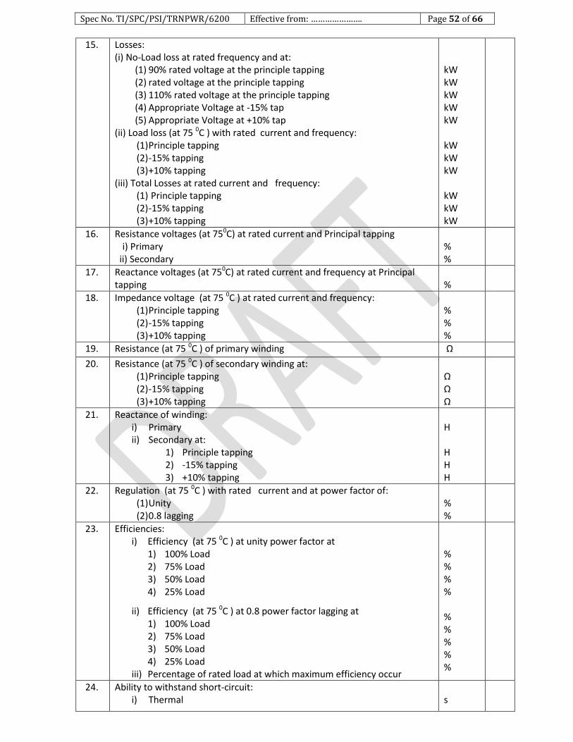
Spec No. TI/SPC/PSI/TRNPWR/6200 Effective from: …………………. Page 52 of 66
15. Losses: (i) No-Load loss at rated frequency and at:
(1) 90% rated voltage at the principle tapping (2) rated voltage at the principle tapping (3) 110% rated voltage at the principle tapping (4) Appropriate Voltage at -15% tap (5) Appropriate Voltage at +10% tap
(ii) Load loss (at 75 0C ) with rated current and frequency: (1) Principle tapping (2) -15% tapping (3) +10% tapping
(iii) Total Losses at rated current and frequency: (1) Principle tapping (2) -15% tapping (3) +10% tapping
kW kW kW kW kW kW kW kW kW kW kW
16. Resistance voltages (at 750C) at rated current and Principal tapping i) Primary
ii) Secondary
% %
17. Reactance voltages (at 750C) at rated current and frequency at Principal tapping
%
18. Impedance voltage (at 75 0C ) at rated current and frequency: (1) Principle tapping (2) -15% tapping (3) +10% tapping
% % %
19. Resistance (at 75 0C ) of primary winding Ω
20. Resistance (at 75 0C ) of secondary winding at: (1) Principle tapping (2) -15% tapping (3) +10% tapping
Ω Ω Ω
21. Reactance of winding: i) Primary ii) Secondary at:
1) Principle tapping 2) -15% tapping 3) +10% tapping
H H H H
22. Regulation (at 75 0C ) with rated current and at power factor of: (1) Unity (2) 0.8 lagging
% %
23. Efficiencies: i) Efficiency (at 75 0C ) at unity power factor at
1) 100% Load 2) 75% Load 3) 50% Load 4) 25% Load
ii) Efficiency (at 75 0C ) at 0.8 power factor lagging at 1) 100% Load 2) 75% Load 3) 50% Load 4) 25% Load
iii) Percentage of rated load at which maximum efficiency occur
% % % % % % % % %
24. Ability to withstand short-circuit: i) Thermal
s

Spec No. TI/SPC/PSI/TRNPWR/6200 Effective from: …………………. Page 53 of 66
ii) Dynamic s
25. Thermal time constant (calculated) i) For primary and secondary windings with respect to oil at :
1) Rated current 2) 150% Rated current 3) 200% Rated current
ii) Complete Transformer at rated current
min min min min
26. Temperature gradient between oil and winding at: i) rated current ii) 150% rated current for 15 min.
iii) 200% rated current for 5 min.
0C 0C 0C
27. Temperature rise of oil: i) Calculated average temperature rise of oil at
1) Rated current 2) 150% rated current for 15 min. 3) 200% rated current for 5 min.
ii) Estimated temperature rise of top oil at: 1) Rated current
2)150% rated current for 15 min. 3)200% rated current for 5 min.
0C 0C 0C 0C 0C 0C
28. Details of core: i) Type of core ii) Flux density at principal tapping at rated voltage and frequency. iii) Flux density at principal tapping at 110% rated voltage and frequency. iv) Thickness of steel stampings v) Grade of core material and conforming specification. vi) Exciting VA/kg for core stampings at: 1) Flux density of 1.55 tesla 2) Flux density at rated voltage 3) Flux density at 110% rated voltage
vii) Exciting VA/kg for assembled core at: 1) Flux density of 1.55 Tesla 2) Flux density at rated voltage 3) Flux density at 110% rated voltage.
viii) Type of insulation between core laminations ix) Type of joint between the core limbs and yoke. x) Core bolt Insulation withstand voltage xi)Core bolt insulation flashover voltage
Tesla Tesla mm VA/kg VA/kg VA/kg VA/kg VA/kg VA/kg kV kV
29. Details of windings: i)Type of winding:
1) Primary 2) Secondary 3) Number of turns of primary winding 4) Number of turns of secondary Winding 5) Number of parallel paths in primary winding 6) Number of parallel paths in secondary winding 7) Is interleaving/intershielding of the winding adopted to ensure better
impulse voltage distribution in primary winding? 8) Is inter leaving/interhielding of the winding adopted to ensure better
impulse voltage distribution in secondary winding? 9) Is the insulation of end turns of primary winding reinforced?
Yes/No
Yes/No Yes/No

Spec No. TI/SPC/PSI/TRNPWR/6200 Effective from: …………………. Page 54 of 66
10) Is the insulation of end turns of secondary winding reinforced? ii) Mode of connection ( i.e. in series or in parallel ) of the portions of the
primary and secondary windings on the two limbs of the core, if applicable:
1) Primary 2) Secondary
iii) Dimensions of the copper conductor used in the winding: 1) Primary 2) Secondary 3) Tapped winding
iv)Current density at rated current: 1) Primary 2) Secondary
v) Insulation used over the conductor (details of material and specification thereof)
vi)Type of joints , if any ,in the windings vii) Dielectric strength for windings : 1) Full wave lightening Impulse withstand voltage:
a) Primary winding b) Secondary winding
2)Lightening impulse chopped on tail withstand voltage: a) Primary winding b) Secondary winding
3)Separate source power frequency withstand voltage: a) Primary winding b) Secondary winding
4)Induced overvoltage withstand value viii) Minimum flashover distance to earth in oil of :
1) Secondary winding to core 2) Primary winding to yoke 3) Primary winding to tank
ix) Material used for coil clamping rings and specification thereof x) Can either end of secondary winding be connected directly to earth? xi) Magnitude of axial precompressive force on the windings:
a) Primary b) Secondary
xii) Calculated maximum axial thrust in the windings due to dead short at the terminals:
a) Primary b) Secondary
xiii)Calculated short circuit forces: 1) Hoop stress in primary winding 2) Hoop stress in secondary winding 3) Compressive pressure in the radial spacers 4) Internal axial compressive force 5) Axial imbalance force 6) Resistance to collapse 7) Bending stress on clamping ring 8) Radial bursting force
xiv) Arrangement to maintain constant pressure on the windings xv) Maximum permissible torque on pressure screws for coil clamping at the time of tightening, if any.
Yes/No
mmxmm mmxmm mmxmm
A/mm2 A/mm2
kV peak kV peak
kV peak kV peak
kV kV kV
mm mm mm
Yes/No
T T
T T
kgf/cm2 kgf/cm2 kgf/cm2
kgf kgf kgf
kgf/cm2 kgf
Nm

Spec No. TI/SPC/PSI/TRNPWR/6200 Effective from: …………………. Page 55 of 66
30. Motorized off-circuit tap-changer i) Name of the manufacturer ii) Country of origin iii) Type designation iv) Governing specification v) Is a separate tapped winding provided on secondary vi) Number of tappings:
1) Plus tappings 2) Minus tappings
vii) Percentage variation of voltages on different tappings viii) Minimum contact pressure between moving and stationary contacts ix) Maximum rated through current x) Voltage class xi) Rated voltage of control circuit xii) Tap changer motor particulars :
1) Make and type 2) Rated voltage 3) Rated current 4) Rated power 5) Speed 6) Class of insulation
Yes/No
% kg A kV
V(DC)
V (DC)
kW rpm
31. Bushings: i) Primary side: 1) Name of the manufacturer 2) Country of origin 3) Governing specification 4) Type designation (specify as to whether it is OIP condenser Bushing) 5) Voltage class 6) Rated current 7) Visible power frequency discharge voltage 8) Wet one minute power frequency withstand voltage 9) Lightening impulse withstand voltage 10) Creepage distance 11) Weight of assembled bushing
ii) Secondary side: 1) Name of the manufacturer 2) Country of origin 3) Governing specification 4) Type designation 5) Voltage class 6) Rated current 7) Visible power frequency discharge voltage 8) Wet one minute power frequency withstand voltage 9) Lightening impulse withstand voltage 10) Creepage distance 11) Weight of assembled bushing
kV A
kV rms kV rms kV peak
mm Kg
kV A kV kV
kV peak mm Kg
32. Bushing type current transformers:
i) Primary side: 1) Name of the manufacturer 2) Governing specification 3) Transformation ratio 4) Accuracy Class and rated Accuracy limit factor 5) Rated current
A
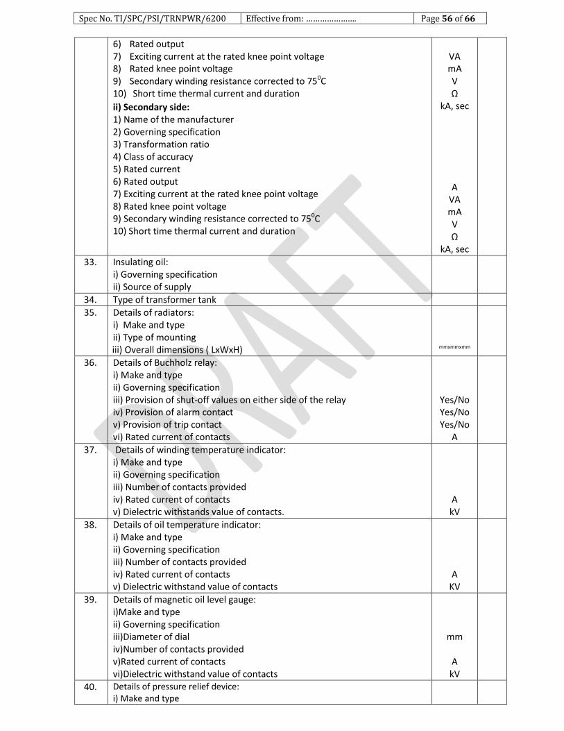
Spec No. TI/SPC/PSI/TRNPWR/6200 Effective from: …………………. Page 56 of 66
6) Rated output 7) Exciting current at the rated knee point voltage 8) Rated knee point voltage 9) Secondary winding resistance corrected to 750C 10) Short time thermal current and duration
ii) Secondary side: 1) Name of the manufacturer 2) Governing specification 3) Transformation ratio 4) Class of accuracy 5) Rated current 6) Rated output 7) Exciting current at the rated knee point voltage 8) Rated knee point voltage 9) Secondary winding resistance corrected to 750C 10) Short time thermal current and duration
VA mA V Ω
kA, sec
A VA mA V Ω
kA, sec
33. Insulating oil: i) Governing specification ii) Source of supply
34. Type of transformer tank
35. Details of radiators: i) Make and type ii) Type of mounting iii) Overall dimensions ( LxWxH)
mmxmmxmm
36. Details of Buchholz relay: i) Make and type ii) Governing specification iii) Provision of shut-off values on either side of the relay iv) Provision of alarm contact v) Provision of trip contact vi) Rated current of contacts
Yes/No Yes/No Yes/No
A
37. Details of winding temperature indicator: i) Make and type ii) Governing specification iii) Number of contacts provided iv) Rated current of contacts v) Dielectric withstands value of contacts.
A kV
38. Details of oil temperature indicator: i) Make and type ii) Governing specification iii) Number of contacts provided iv) Rated current of contacts v) Dielectric withstand value of contacts
A KV
39. Details of magnetic oil level gauge: i)Make and type ii) Governing specification iii)Diameter of dial iv)Number of contacts provided v)Rated current of contacts vi)Dielectric withstand value of contacts
mm
A kV
40. Details of pressure relief device: i) Make and type
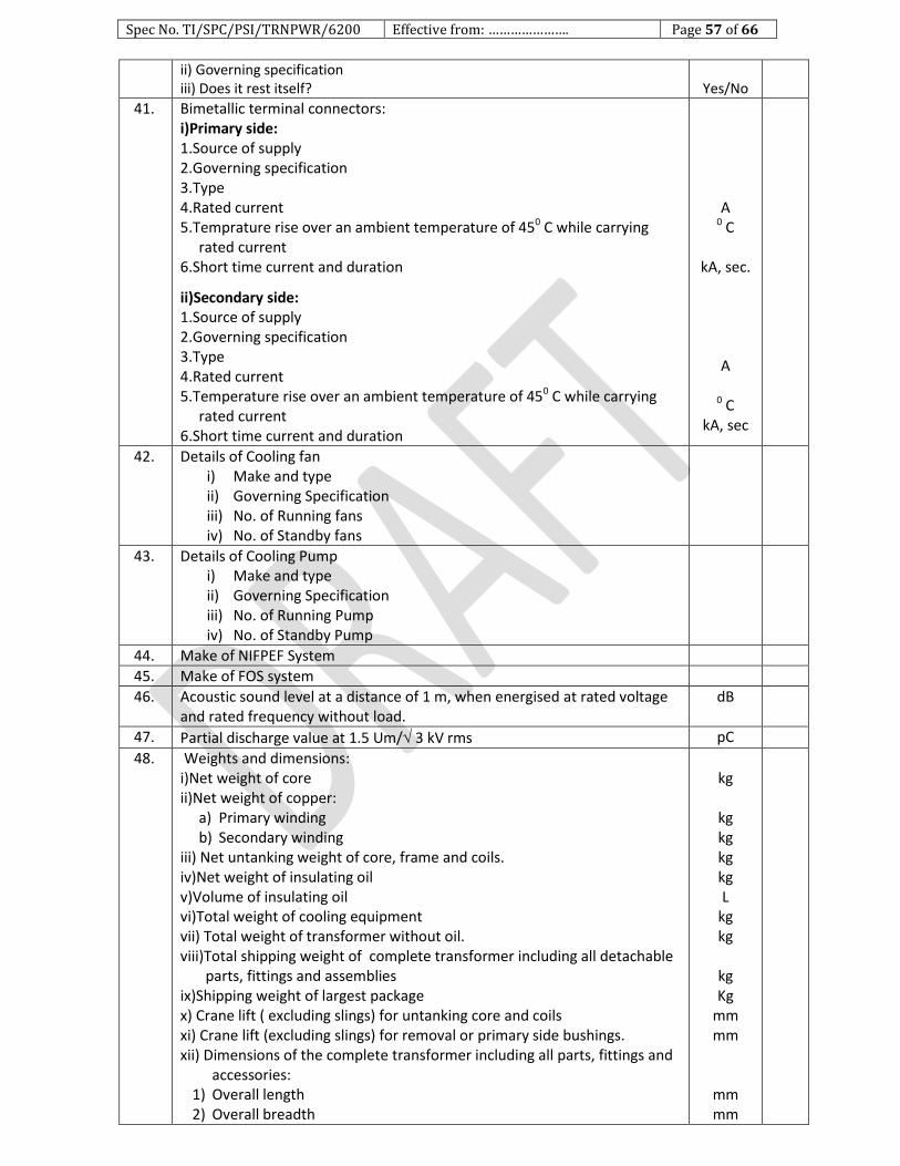
Spec No. TI/SPC/PSI/TRNPWR/6200 Effective from: …………………. Page 57 of 66
ii) Governing specification iii) Does it rest itself?
Yes/No
41. Bimetallic terminal connectors: i)Primary side: 1.Source of supply 2.Governing specification 3.Type 4.Rated current 5.Temprature rise over an ambient temperature of 450 C while carrying
rated current 6.Short time current and duration
ii)Secondary side: 1.Source of supply 2.Governing specification 3.Type 4.Rated current 5.Temperature rise over an ambient temperature of 450 C while carrying
rated current 6.Short time current and duration
A 0 C
kA, sec.
A
0 C kA, sec
42. Details of Cooling fan i) Make and type ii) Governing Specification iii) No. of Running fans iv) No. of Standby fans
43. Details of Cooling Pump i) Make and type ii) Governing Specification iii) No. of Running Pump iv) No. of Standby Pump
44. Make of NIFPEF System
45. Make of FOS system
46. Acoustic sound level at a distance of 1 m, when energised at rated voltage and rated frequency without load.
dB
47. Partial discharge value at 1.5 Um/ 3 kV rms pC
48. Weights and dimensions: i)Net weight of core ii)Net weight of copper:
a) Primary winding b) Secondary winding
iii) Net untanking weight of core, frame and coils. iv)Net weight of insulating oil v)Volume of insulating oil vi)Total weight of cooling equipment vii) Total weight of transformer without oil. viii)Total shipping weight of complete transformer including all detachable
parts, fittings and assemblies ix)Shipping weight of largest package x) Crane lift ( excluding slings) for untanking core and coils xi) Crane lift (excluding slings) for removal or primary side bushings. xii) Dimensions of the complete transformer including all parts, fittings and
accessories: 1) Overall length 2) Overall breadth
kg
kg kg kg kg L
kg kg
kg Kg
mm mm
mm mm

Spec No. TI/SPC/PSI/TRNPWR/6200 Effective from: …………………. Page 58 of 66
3) From rail level to the topmost point xiii) Minimum thickness of steel plate/ sheet used:
1) Bell tank 2) Tank bottom 3) Conservator 4) Radiator 5) Marshalling box. 6) Tap changer cubicle.
xiv) Overall shipping dimensions of the largest package ( LxBxH) xv) Mode of transportation of transformer unit (filled with Oil/nitrogen
gas)
mm
mm mm mm mm mm mm
mm x mm x mm
B. Other Particulars
49. Is the transformer tank fitted with lifting pads? If yes what is the numbers of pads?
Yes/No
50. What is the number of inspection covers provided? Nos.
51. Are conduits/trays provided for cable run? Yes/No
52. Is the core electrically connected with the tank? Yes/No
53. Will the gaskets to be used in the transformer give trouble free service for at least 12 years? If not indicate the life.
Yes/No
54. Is the core construction without core bolts? Yes/No
55. Are the core bolts grounded, and if so how? Yes/No
56. Are the magnetic shunt pockets of core lamination provided inside the tank surface to absorb stray flux? If yes, the material specification shall be furnished
Yes/No
57. What is the number of radial spacers used in the: i) Primary windings ii) Secondary windings.
58. What is the number of joints provided in the : i) Primary windings ii) Secondary windings.
59. Are the spacers/blocks/angle rings of pre-compressed press boards? If no, indicate the material with specification.
Yes/No
60. Are arrangements made for ensuring automatic constant pressure on the coils? If no give the reasons.
Yes/No
61. Are the closed slots provided on the outer most winding for locking the vertical strips? If no give the reasons
Yes/No
62. What is the periodicity for tightening of the coil clamping arrangement Years
63. What are the calculated short circuit currents for : i)Symmetrical:
1) Primary winding 2) Secondary winding.
ii)Asymmetrical: 1) Primary winding 2) Secondary winding.
A A A A
64. What is the over flux withstand capability of the transformer (max. permissible limit of flux density)?
Tesla
65. Are windings pre-shrunk? Yes/No
66. Have the details of drying cycles of the coils/coil assembly including final tightening values of pressure, temperature and degree of vacuum at various stages of drying been furnished?
Yes/No
67. Are arcing horns provided for bushings? Yes/No.
68. Is a test tap provided in each of the primary side and secondary side bushings?
Yes/No
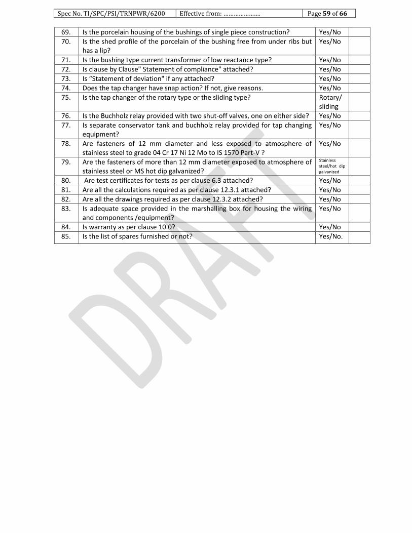
Spec No. TI/SPC/PSI/TRNPWR/6200 Effective from: …………………. Page 59 of 66
69. Is the porcelain housing of the bushings of single piece construction? Yes/No
70. Is the shed profile of the porcelain of the bushing free from under ribs but has a lip?
Yes/No
71. Is the bushing type current transformer of low reactance type? Yes/No
72. Is clause by Clause" Statement of compliance" attached? Yes/No
73. Is “Statement of deviation" if any attached? Yes/No
74. Does the tap changer have snap action? If not, give reasons. Yes/No
75. Is the tap changer of the rotary type or the sliding type? Rotary/ sliding
76. Is the Buchholz relay provided with two shut-off valves, one on either side? Yes/No
77. Is separate conservator tank and buchholz relay provided for tap changing equipment?
Yes/No
78. Are fasteners of 12 mm diameter and less exposed to atmosphere of stainless steel to grade 04 Cr 17 Ni 12 Mo to IS 1570 Part-V ?
Yes/No
79. Are the fasteners of more than 12 mm diameter exposed to atmosphere of stainless steel or MS hot dip galvanized?
Stainless steel/hot dip galvanized
80. Are test certificates for tests as per clause 6.3 attached? Yes/No
81. Are all the calculations required as per clause 12.3.1 attached? Yes/No
82. Are all the drawings required as per clause 12.3.2 attached? Yes/No
83. Is adequate space provided in the marshalling box for housing the wiring and components /equipment?
Yes/No
84. Is warranty as per clause 10.0? Yes/No
85. Is the list of spares furnished or not? Yes/No.

Spec No. TI/SPC/PSI/TRNPWR/6200 Effective from: …………………. Page 60 of 66
Annexure-4
FORMULA FOR CALCULATION OF SHORT CIRCUIT MECHANICAL FORCES
Nomenclature
Ai=Total supported area of the inner radial spacer in cm2.
Ao=Total area of the outer radial spacer in cm2.
At=Area of tie rods in cm2.
a=per unit turns, out of circuit, in the winding.
bi=Thickness of inside winding conductor in cm.
Dmi=Mean diameter of inside winding in cm.
di=Diameter of inner winding conductor in cm.
=Current density in A/cm2
E=Modulus of Elasticity of conductor in kg/cm2
ez=per unit impedance
Fa=Axial imbalance force due to tapping within winding in kgf.
Fc=Internal axial compression force in kgf.
Fr=Radial bursting force in kgf.
hw=Winding height in cm.
Iph=Rated phase current in A.
Isc=First peak value of asymmetrical short circuit current in A.
N=Number of turns per phase in the circuit.
Ns=Number of supports to be provided in the winding.
Nt=Number of the tie rods.
Pi=Compressive pressure in the inner radial spacers in kg/cm2.
Po= Compressive pressure in the outer radial spacers in kg/cm2.
Pt=Tensile stress in the rods in kg/cm2.
R=Sum of the resistance of the transformer and system in ohm.
Rdc=dc resistance of the phase at 750c in ohm.
Sn=Rated kVA.
X=Sum of he reactance of the transformer and system in ohm.
m= Hoop or compressive stress in kg/cm2..
Scope
The calculation methods discussed below would be applicable to two winding
transformers, having core type construction and concentric winding with tapppings
placed within the body of the outer winding.
1. Calculation of first peak value of Asymmetrical short circuit current.
Isc=k2(Iph/e)A.
k2 values are appended below(Ref. IS:2026 Part-I Clause 16.11.2)
X/R= 1 1.5 2 3 4 5 6 8 10 14
k2= 1.51 1.64 1.76 1.95 2.09 2.19 2.27 2.38 2.46 2.55
Note: For other values of X/R between 1 and 14 , the factor k2 may be determined by linear
interpolation.
2. Calculation of Asymmetrical short circuit Ampere-turns : N x Isc
3. Hoop Stress
m=(kxIph2 x Rdc) / (hw x ez
2) kg/cm
2
k (Cu)=0.03(k2)2/(2.55)

Spec No. TI/SPC/PSI/TRNPWR/6200 Effective from: …………………. Page 61 of 66
k2 as derived from item 1 above.
The figure so calculated shall be less than 1250kg/cm2..
Note: The value of (Iph2xRdc)/hw referred to inner or outer winding shall be incorporated in the
formula depending upon whether inner or outer winding stress is required to be calculated.
4. Radial Bursting force
Fr =(2 x m x Iph x N) / kg.
5. Number of supports to be provided in winding (Flat conductor )
Ns= (Dmi x12xm)/(bi x E)
Where,E=1.13x10⁶ kg/cm
2.
6. Number of supports to be provided in winding (Round conductor)
Ns=( 8x Dmi x m) / ( di x E)
m as derived from item 3 above.
7. Calculation of internal axial compression
Fc=(-) (34Sn)/ (ez x hw) kg.
Note: 1/3 Fc is acting on outer winding.
2/3 Fc is acting on inner winding
(-) Indicates that force is acting towards the centre.
8. Calculation of Axial imbalance force due to tapping within the windings
Fa=(a/2) x (NIsc)2x10
-7kg.
Note 1 : If tapping are divided into two groups between the centre and the end of the windings ,
the force will be reduced to 1/4th of the figure obtained by the above formula.
Note 2 : If the compensating gap is provided in the untapped winding , the force will be half of
that calculated above.
Note 3 : For multi layer single coil design and other modes of Ampere-turn balancing actual
unbalance Ampere-turns can be determined by residual Ampere-turn diagram.
9. Calculation of Maximum compressive pressure in the radial spacers
Pi=(Fa+2/3Fc)/Ai kg/cm2
Po=(Fa+1/3Fc)/Ao kg/cm2
Note: Value calculated should not exceed 300kg/cm2 for normal calandered press boards and
500kg/cm2 for precompressed press boards.
10. Calculation of tensile stress in the tie rods
Pt=(Fa - 1/3Fc)/(Nt x At) kg/cm2.
Fa as derived from item - 8 above & Fc as derived from item - 7 above.
Note: The value calculated should be less than 2500kg/cm2 for Mild steel tie rods.
11. Calculation of Resistance to Collapse
(Applicable only to disc winding using rectangular conductor)
F(Crit)=1.5E(Iph)2x (m) / bo x Dmo x
2 x 10
8 + (450xAoxxb
3) / Iph t, Where:
E =Modulus of Elasticity of conductor in kg/cm2.
m =Number of turns x number of Parallel Conductors per coil
Iph =Rated phase current in A.
bo = Thickness of outer winding conductor in cm

Spec No. TI/SPC/PSI/TRNPWR/6200 Effective from: …………………. Page 62 of 66
Dmo =Mean diameter of outer winding in cm.
= Current density in A/mm2
Ao =Total supported area of the outer radial spacer in cm2.
12. Calculation of most highly Stressed Coil: (Applicable for tapped winding only)
fa=(0.733 Q x Fr x log10(2aNc+1) t, where:
Q =Turns per coil adjacent to tapped out of coil, expressed as fraction of total turns
in the limb.
Fr =Radial force as derived from item - 4 above.
A = Per unit number of turns out of circuit.
Nc = Number of coils per limb.
13. Calculation of 'W' i.e. mechanical loading per centimeter of periphery
Wl = (fa)/(xDm) kg/cm, Where :
Fa = Value as derived from item-12 above in kg.
Dm = Mean diameter of tapped winding in cm.
Add 25% extra for concentration of force and assume W = 1.25Wl.
max = (WxL2xY) / (12xIo) kg/cm
2 , where :
L =Span in cm = (xDm / ns) x bs
ns =Number of spacers .
bs = Width of spacer in cm
Y = Maximum distance from neutral axis for conductor in cm i.e. axial height of the
winding across the neutral axis divided by 2.
Io =Moment of inertia of the coil i.e. bd3/12
b =Radial depth of coil in cm.
d =Axial height of coil in cm
Maximum permissible value for max is 1250kg/cm2.
14. Calculation of bending stress on clamping rings: The stress on circular ring is as
below:
max=(6 x F x D) /(8 b x t2x n
2) t/cm
2 , where :
F =Total axial force (Fa-1/3Fc) in t.
Fa =Value as derived from item - 8 above.
Fc = Value as derived from item - 7 above.
D = Diameter of ring in cm.
b =Width of ring in cm.
t =Thickness of ring in cm.
n =Number of jacking points.
Maximum permissible value for max is 1100kg/cm, if circular permawood ring is used.
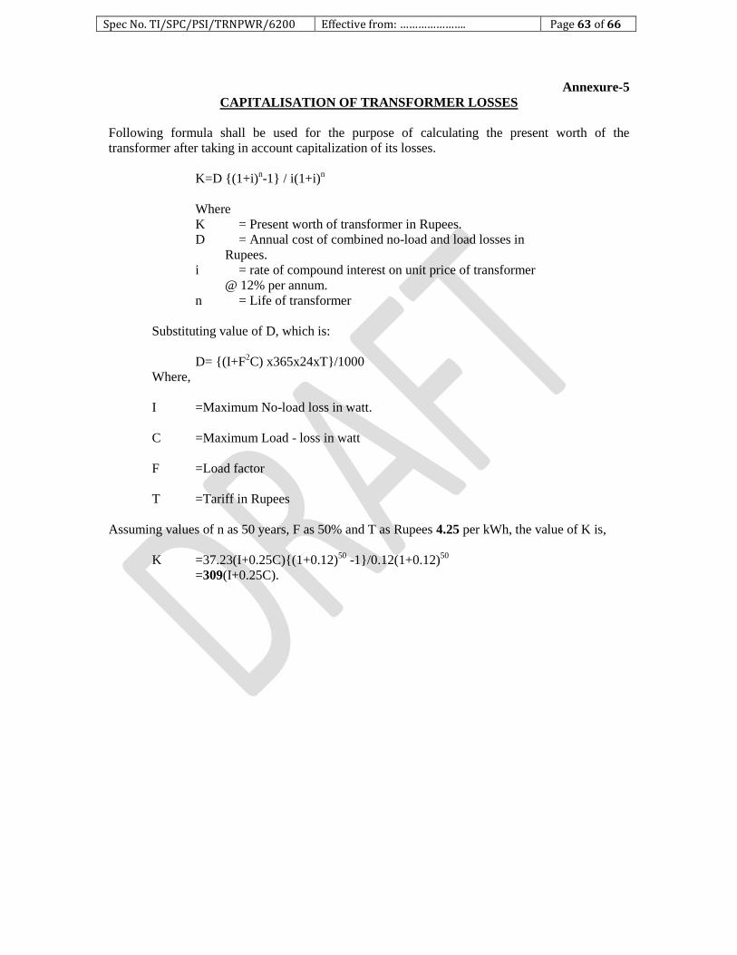
Spec No. TI/SPC/PSI/TRNPWR/6200 Effective from: …………………. Page 63 of 66
Annexure-5
CAPITALISATION OF TRANSFORMER LOSSES
Following formula shall be used for the purpose of calculating the present worth of the
transformer after taking in account capitalization of its losses.
K=D (1+i)n-1 / i(1+i)
n
Where
K = Present worth of transformer in Rupees.
D = Annual cost of combined no-load and load losses in
Rupees.
i = rate of compound interest on unit price of transformer
@ 12% per annum.
n = Life of transformer
Substituting value of D, which is:
D= (I+F2C) x365x24xT/1000
Where,
I =Maximum No-load loss in watt.
C =Maximum Load - loss in watt
F =Load factor
T =Tariff in Rupees
Assuming values of n as 50 years, F as 50% and T as Rupees 4.25 per kWh, the value of K is,
K =37.23(I+0.25C)(1+0.12)50
-1/0.12(1+0.12)50
=309(I+0.25C).
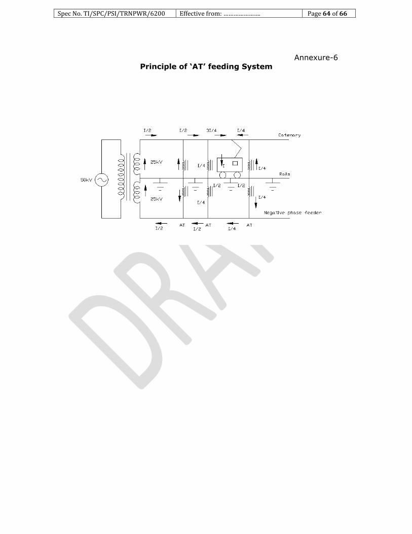
Spec No. TI/SPC/PSI/TRNPWR/6200 Effective from: …………………. Page 64 of 66
Annexure-6 Principle of ‘AT’ feeding System
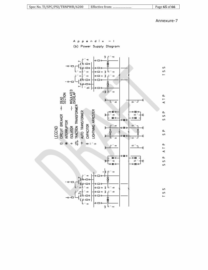
Spec No. TI/SPC/PSI/TRNPWR/6200 Effective from: …………………. Page 65 of 66
Annexure-7