specification oyster creek · 2012-11-29 · is-328227-004 function requiremenu for diywell...
TRANSCRIPT
0
e
0
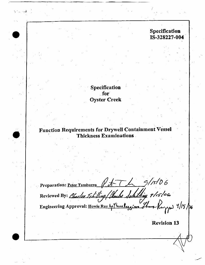
Specification IS-328227-004
Specification for
Oyster Creek
Function Requirements for Drywell Containment Vessel Thickness Examinations
Preparation: Peter Tamburro
Reviewed By: &/# Engineering Approval: Bo
Revision 13
L
1 DOCUMENT NO.
- REV - 13
0
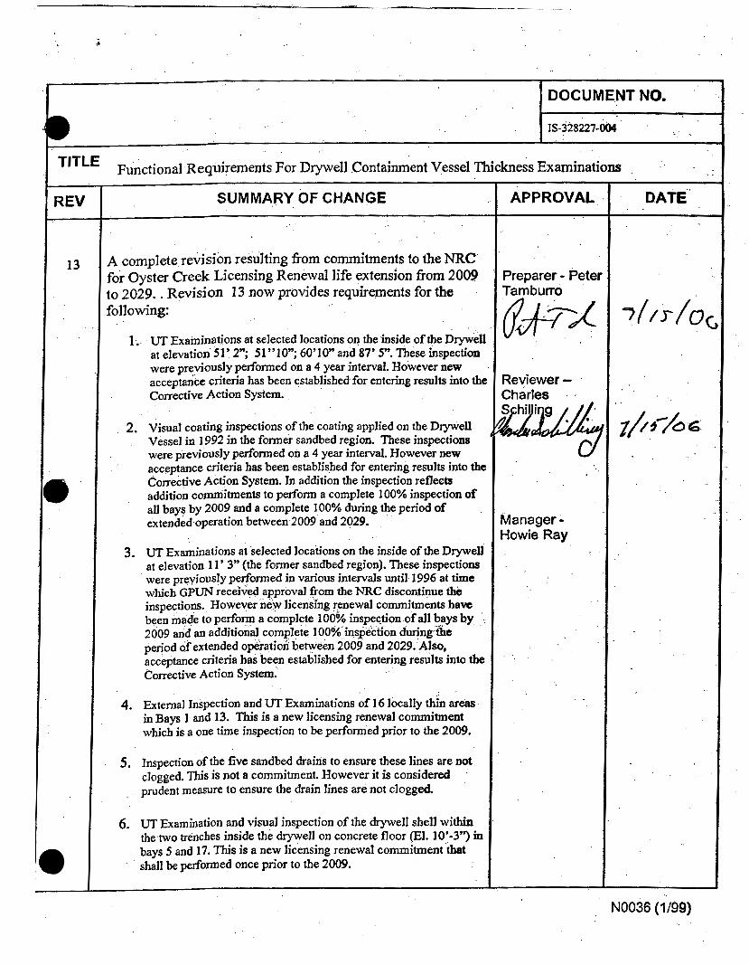
A complete revision resulting fiom commitments to the NRC for Oyster Creek Licensing Renewal life extension fiom 2009 to 2029. . Revision 13 now provides requirements for the following:
1.
2.
3.
4.
5.
6.
UT Examinations at selected locations on the inside of the Drywell at elevation 51’ 2”; 51”1O”; 60’10” and 87’ 5”. These inspection were p r e v i ~ ~ s l y performed on a 4 year interval. However new acceptance criteria has been established for entering results into the corrective Action System.
Visual coating inspections of the coating applied on the Drywell Vessel in 1992 in the former sandbed region. These inspections were previously pedormed on a 4 year interval. However new acceptance criteria has been established for entering results into the Corrective Action System. In addition the inspection reflects addition commitments to perfom a complete 100% inspection of a]] bays by 2009 and a complete 100% during the period of extended operation between 2009 and 2029.
UT Examinations at selected locations on the inside of the Drywell at elevation 11’ 3” (the former sandbed region). These inspections were previously performed in van’ous intervals until 1996 at time which G P m received approval fiom the NRC discontinue the inspections. However new licensing renewal commitments have been made to perform a complete 100% in 2009 and an additional complete 100% ins period of extended operation between 2009 and 2029. Also, acceptance criteria has been established for entering results into thc Corrective Action System.
External Inspection and UT Examinations of 16 locally thin areas in Bays 1 and 13. This is a new licensing renewal commitment which is a one time inspection to be performed prior to the 2009.
Inspection of the five sandbed drains to ensure these lines are not clogged. This is not a commitment. However it is considered prudent measure to ensure the drain lines are not clogged.
UT Examination and visual inspection of the drywell shell withh the two trenches inside the drywell on concrete floor (El. 10’-3”) h bays 5 and 17. This is a new licensing renewal commitment that shall be performed once prior to the 2009.
-
APPROVAL , .
’reparer - Peter ramburro
Reviewer- ’
Charles .
DATE.‘
Manager - Howie Ray
NO036 (1 /99)

. . i . .
7. UT Examination of a welds at Elevation 23’ 6”. This is a new licensing renewal commitment, which shall be pexformed once prior to the 2009 and once during the period of extended operation.
8. UT Examination of a weld at Elevation and 71’6”. This is a new licensing renewal commitment, which shall be performed once prior to the 2009 and once during the period of extended operation.
. .
NO036 (1/99)

IS-328227-004 Function Requiremenu for Diywell Containmeni Vessel ntickness Exominarions Rev. 13
Page 2 of 37
1.0 Scope This specification estabIishes requirements for Non Destructive Examination (NDE) of the Oyster Creek Drywell Containment Vessel. This specification has been revised due to Licensing Renewal Commitments in reference 2.1 9. The following inspections and examinations are
. addressed:
1) UT (Ultrasonic Thickness) Examinations at selected locations on the inside of the Drywell at elevation 5 1 ’ 2”; 5 1 ’ IO”; 60’1 0” and 87’ 5”. The purpose of these examinations is to monitor long term corrosion rates at these elevations.
2) Visual coating inspections (VT-I) of the coating applied on the Drywell Vessel exterior in 1992 in the former sandbed region. The purpose of these inspections is to ensure that the condition of the coating is acceptable and meets Section XI, Subsection W E requirements. These inspections are required to meet Oyster Creek License Renewal commitments.
3) UT Examinations at selected locations inside the Drywell at elevation 11’ 3” (the former sandbed region). The purpose of these examinations is to verify that the external coating is effectively protecting the drywell vessel and that external corrosion is insignificant. These inspections are required to meet Oyster Creek License Renewal commitments.
4) External UT Examinations of locally thin areas in Bays I and 13. The purpose of these examinations is to attempt to locate and measure locally thin areas that were identified dun’ng external inspections in 1992. These inspections are required to meet Oyster Creek License Renewal commitments, These UT inspections will be performed through existing coating.
5) Inspect the sandbed drains to ensure these lines are not clogged. These inspections will ensure that the sandbed drains are not clogged and water will not collect in the former sandbed region and challenge the coating.
6) UT Examination and visual inspection of the drywell shell within the two trenches inside the drywell on concrete floor (El. 10’”’’) in bays 5 and 17. The purpose of these examhations is to verify that the internal coating in the trenches is effectively protecting the drywell vessel and that external corrosion is insignificant. These inspections are required to meet Oyster Creek License Renewal commitments.
7) UT Examination of the weld joint at Elevation 23’ 6 7/8”. The purpose of this examination is to provide an indication that the drywell vessel at this weld has not significantly degraded. This inspection is required to meet Oyster Creek License Renewal commitments. This UT inspection will be performed through existing internal coating.
8) UT Examination of the weld joint at Elevation 71 ’ 6”. The purpose of this examination is to provide an indication that the drywell vessel at this weld has not significantly degraded. This inspection is required to meet Oyster Creek License Renewal commitments. This UT inspection will be performed through existing coating.

. .
. .
IS-328227-004 Function Requirements for Drywell Containment Vessel nichess Examinatiom Rev. 13
Page 3 of 37
2.0 Reference
Unless otherwise noted, the latest revision applies.
2.1
2.2
2.3
2.4
2.5
2.6
2.7
2.8
2.9
I
ASME B&PV Code Section V, 1986 Edition
ASME B&PV Code Section XI, Subsection IWE, 3 992 Edition
C- 1302-1 87-E3 10-030 Revision 1, “Statistical Analysis of Drywell Thickness Through September 1996”
TQ-AA-122, “Qualification And Certification of Nondestbctive (NDE) Personnel”
ER-AA-335-004, “Manual Ultrasonic Measurements of Material Thickness and Interf‘erhg Conditions”
GPUN Sketch, No. SK-S-89
GPUN Sketch, No. SK-S- 85
C-1302-187-E310-037 Revision 2, “Statistical Analysis of Drywell Vessel Thickness Data”
C-I 302-1 87-5320-024, Revision 1, “Drywell External Ultrasonic Testing Evaluation in Sandbed”
2.1 0 GPUN Drawing 3E-3 87-29-001, Revision 0, Drywell Shell Stretch-out”.
2.1 I ER-AA-335-018, “Detailed General, VT-3, VT-I C, VT-3 and.VT-3C, Visual Examination of ASME Class MC and CC Containment Surf‘aces and Components”
2.32 OCIS-328227-003,”Repair of Concrete Floor Removed in Drywell For UT Rea dings”
2.13 NRC SER date November I , 1995 - Changes in the Oyster Creek Drywell Monitonng Program
2.14 ECR 05-00275, Drywell Vessel inspections through 2004.
2.1 5 License Renewal Commitment Letter -fi-om M.P. Gallagher to NRC dated April 4,2006 (2 130-06-20284)
2.1 6 ER-OC-330-3 006, “First 3 0 Year Containment (IWE) Inservice Inspection Program Plan and Basis, Draft.

IS-328227-004 Funcrion Requirements for DtyweN Conroinmenr Vessel 7hickness Examinations Rev. 13
Page 4 of 37
2.1 7 PBD-AMP-B.I.27, Program Basis Document ASME Section XI, Subsection IWE.
2.1 8 ER-AA-335-030, “ULTRASONIC EXAMINATION OF FERRITIC PIPING WELDS”
2.19 Commitments
CRI-1 PASSPORT AR 00330592.27, Oyster Creek Licensing Renewal Commitments Associated with Aging Management Program B.l.27, ASME Section XI, Subsection IWE (Steps 1 .O)
0 CM-2 PASSPORT AR 00330592.33, Oyster Creek Licensing Renewal Commitments Associated with Aging Management Program B. 1.33, Protective Coating Moniton’ng and Maintenance Program
. .
. .

i 1
0 . .
Function Requiremenu for Diywell Containment Vessel ntickness Eraminotiom
3 Requirements
3.1 Non Destructive Examinations
3.1.1 Personnel Qualification
18-328227-004 Rev. 13
Page 5 of 37
3.1.2
3.13
3.1.1 .l Personnel conducting Ultrasonic Exam natlms shall be qualified in accordance with ER-AA-335-004.
3.1.1.2 Personnel conducting Visual Examinations shall be VT-1 qualified in accordance with ER-AA-335-018.
Examination Procedures
3.1.2.1 NDE UT examinations shall be performed in accordance with ER-AA-335-004 and this specification.
3.1.2.2 Visual Examination of the Drywell Vessel coating on the exterior surface of the former sandbed region and the internal portions of the trenches shall be performed in accordance with ER-AA-335-018.
3.1.2.3 NDE UT examinations of welds (in section 3.2.7 and 3.2.8) shall be performed in accordance with ER-AA-335-030 and this specification.
R!Tethodology and Equipment The UT examinations performed inside the Drywell shall be performed by one of the following methods:
3.1.3.1 Forty Nine Point Examinations
3.1.3.1.1 For these locations the inspector shall use a stainless steel template fabricated in accordance with Exhibit 2.
3.1.3.1.2 Prior to inspection remove the existing grease that has been previously applied on the area for corrosion protection.
At each location, the template shall be placed on the drywell vessel so that the notches on the template line up with the low stress die stamps that have been previously stamped on the surface of the drywell. The Inspector shall use a
3.1.3.1.3

i I
. . Funclion Requiremenfi for Drywell Conlainment Vessel 7 l ichess Examinorions
e 3.1.3.1.4
3.1.3.1.5
IS-328227-004 Rev. 13
Page 6 of 37
UT transducer that fits within the template within a clearance of 1/16”.
The UT transducer shall be positioned in the same orientation at each grid point. (Le. the top of the transducer is always positioned to the top template).
After the UT inspection coat the location with Versilube G35 1 grease or an approved alternative.
3.1.3.2 Seven Point Examinations
3.1.3.2.1
3.1.3.2.2
3.1.3.2.3
3.1.3.2.4
3.1.3.2.5
3.1.3.2.6
For these locations the inspector shall use the same stainless steel template fabricated in accordance with Exhibit 2.
Prior to inspection remove the existing the grease that has been previously applied on the area for corrosion protection.
At each location, the template shall be placed on the drywell vessel so that the notches on the template line up with the low stress die stamps that have been previously stamped on the surface of the drywell. The Inspector shall use a UT transducer that fits within the template within a clearance of 1/16”. The inspector shall record only the 7 readings in the middle row.
The UT transducer shall be positioned in the same orientation at each grid point. (Le. the top of the transducer is always positioned to the top of the template).
Use of the template, the UT transducer, and aligning it with the template notches to the stamp on the Drywell ensures that each individual reading is located within a 1/8” of previous readings.
AAer the UT inspection coat the location with Versilube G353 grease or an approved a1 ternative.

IS-328227-004 Function Requirements for Drywell Containment Vessel ?hichess Examinations Rev. 13
Page 7 of 37
’ Bay Area Points 11A 23,24,30,31 17D 15,16,22,23 19A 24,25,31,32
5/D12 (51-D1) 20,26,27,28,33,34,35 19C &
3.3.3.3 Multiple Point Examinations within the two floor Tren ch es
3.1.3.3.1
3.1.3.3.2
3.1.3.3.3
For these two locations the inspector shall use the same stainless steel template fabricated in accordance with Exhibit 2.
Refer to Exhibit 5. Within each trench, place the template at the very bottom of the trench and record the data. After the 49 points are recorded, relocate the template up the trench as shown in Exhibit 5. Ensure the centerline of the bottom row on the relocated template is 1” +/ - 1/16’’ from the previous grid top row. The inspector shall use a UT transducer that fits within the template within a clearance of 1/16”.
The UT transducer shall be positioned in the same orientation at each gfid point. (I.e. the top of the transducer is always positioned to the top of the template). The UT readings shall be taken through the existing coating.
3.1.4 Inspection Schedule All inspections required by this specification shall be performed during the scheduled Refueling Outage for the years shown in the table 4.

i I
IS-328227-004 Function Requirements for D y e 1 1 Containment Vessel i%ickness Examinations Rev. 13
Page 8 of 37
.e 3.2 Inspections
’ 3.2.1 Internal UT Inspection of Upper Elevations A total of nine locations are monitored for corrosion rates at elevation 51’ 2”; 51’ 10”; 60’ IO” and 87’ 5”. Forty-nine individual UT readings shall be recorded at each of the nine locations in accordance with section 3.1.3.1. Table 1 below provides information for each of these locations.
Criteria for each
3.2.1.1 Acceptance Criteria With the exception of individual points positioned over core plugs (as documented is section 3.1.3.4) each individual reading less than the minimum value specified in the table 1 shall be entered into the corrective action program and evaluated by Engineering. The acceptance criteria in table 1 is based on the minimum recorded readings in 2004 (reference 2.8) and a 20 mil tolerance. The acceptance criteria is not based on the minimum required code thickness, which is less than the above values.
3.2.1.2 Data Retention All 49 readings values at each location shall be documented on an NDE data sheet and formatted in a 7 by 7 matrix, which
I
IS-328227-004 Funclion Requiremenrr for D w e l l Conrainment Vessel Thickness Eraminotions Rev. 13
Page 9 of 37
corresponds to the template. The data sheet shall also include: the date and time of the examination, location of core plugs (if applicable), the examination method, the ID number of the equipment, the ID number of the cal block, the location surface temperature, Examiner, Reviewer, the governing procedure, Location ID in accordance with Table 1. Forward the completed data sheets to Engineering.
3.2.1.3 Required Support and Tools
3.2.1.3.1 In order to provide access to the three inspection locations at elevation 87’ 5”, temporary planking shall be provided as necessary at the top of the biological shield extending to the drywell wall.
3.2.1.3.2 Safety and Radcon support and coverage shall be provided as necessary.
3.2.1.3.3 Prior to the UT inspection of each location remove the existing grease that was applied after the last inspection shall be removed.
After the UT inspection coat the location with Versilube G351 grease or an approved a1 ternative.
3.2.1.3.4

IS-328227-004 F u n a i o n Requirements for Dtywell Conlainment Vessel Ihichess Examinations ’ Rev. 13
Page 10 of 37
3.2.2 Internal UT Inspection of Former Sandbed Region Elevations
3.2.2.1 Description /
A total of 19 locations are monitored for corrosion rates at elevation 1 1 ’ 3”. Individual UT readings shall be recorded at each location in accordance with section 3.1.3.1 and 3.1.3.2. Table 2 below provides information for each of these locations.
Table 2- Sandbed Elevation Inspection Location No of I Bay I Elevation I Original 1 Average I Average I Average -~
Location ID
9D 11A 11c 13A ’
13D 15D 17A 17D 17/19 1 9A 1 9B 3 9c
ID
3.2.2.2 Acceptance Criteria
3.2.2.2.1 With the exception of individual points positioned over core plugs each of the 49 individual readings less than 0.628” shall be entered into the corrective action program and

__ __
13-328227-004 Rev. 13
Page 11 of 37 Function Requiremenu for Dtywell Containment Vessel 7Mckness Examinotiom *
3.2.2.2.2
evaluated by Engineen’ng. This acceptance criteria is based on the minimum recorded readings in 1994 (reference 2.3) and a 20 mil tolerance. Acceptance criteria is not based on the minimum required code thickness, which is less than 0.628”.
In addition Engineering shall calculate the average value of each location consistent with reference 2.3. The calculated average for each location shall be within +/- 0.020” of the values documented in table 2. Values not within +/- ’
0.020” shall be entered into the corrective action program and evaluated by Engineering and shall be subject to the following actions:
Perform additional UT measurements to confirm the readings
Notify NRC within 48 hours of confirmation of the identified condition
Conduct inspection of the coatings in the sand bed region in areas where the additional corrosion was detected.
Perfom engineering evaluation to assess the extent of the condition and to determine if additional inspections are required to assure drywell integrjty.
Perfom operability determination and justification for continued operation, in accordance with plant procedures, until next sch edul ed in specti on.
3.2.2.3 Data Retention Values at each location shall be documented on an NDE - . data sheet and formatted in a either 7 by 7 or a 1 by 7 matrix, which corresponds to the template. The data sheet shall also include: the date and time of the examination, location of the core plugs, the examination method, the ID number of the equipment, the governing procedure, the ID number of the cal block, the location surface temperature, Examiner, Reviewer, Location ID in accordance with table 2. Forward the completed data sheets to Engineering.

- k
IS-328221-004 Funcrion Requirementsfor Dlywell Conroinment Vessel 7%ickness fiominoliom Rev. 13
Page 12 of 37
3.2.2.4 Required Support and Tools
3.2.2.4.1 i- Safety and Radcon support and coverage shall be provided as necessary.
3.2.2.4.2
3.2.2.4.3
Prior to the UT inspection of each location remove the existing grease (with an approved cleaner), which was previously applied after the last inspection.
After the UT inspection coat the location with Versilube G351 grease or an approved alternative.

L
Bay
I
IS-328227-004 Rev. 13
Page 13 of 37
3.2.3 External UT Inspection of Locally Thin Areas in Bays 1 and 13
Function Requiremenu for Dtyweil Containment Vessel 73ickness Exominorions
’ Point Vertical Horizontal Measured Number Location , Locatjon Lowest
3.2.3.1 Description
13
3.2.3.1.1
1 up 1” Right 45” 0.672 2 up I ” Right 38” 0.729 5 Down 2 1 ” Right 6” 0.718 6 Down 24” Left 8” 0.655 7 Down 17” Left 23” 0.61 8
Locate and perform UT Inspection of 16 locally thin areas found during the external inspection of the Drywell in 1992, These areas were identified in NDE data sheets 92-072-01 through 92-072-26. Perform the UT inspection through the coating. Select UT equipment that is capable of subtracting the coating thickness from the vessel wall thickness.
3.2.3.1.2
3.2.3.1.3
The inspections shall capture the size of each area for all areas thinner than 0.736”. Characterize the thicknesses within this‘area by recording the top, bottom, left, right, cent& and minimum thickness,
Table 3 below provides information for each of these locations. Locations are based on the distance from the vertical weld at the centerline of the vent line (horizontal) and the vent line penetration weld at the centerline (vertical). See NDE data sheet 92-072-01 and 02.
Reference
92-072-1 2 92-072-12 92-072- 12 92-072-1 2 92-072-12 92-072- 1 8 92-072-1 8
92-072-24- 92-072-24 92-072-24
I S-32 8227-004 Function Requirements for Dtywell Conroinmenr Vessel 7%ichess Exominations Rev. 13
Page 14 of 37
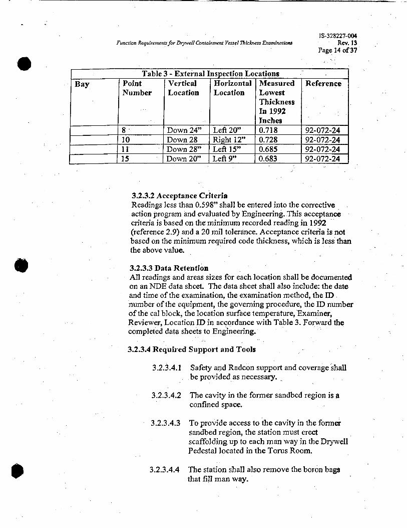
I Table 3 - External Inmection Locations I Bay Point Vertical Horizontal
Number Location Location Measured Lowest Thickness In 1992 Inches -
8 . Down24” . Left20” 0.7 18 10 Down 28 Right 12” 0.728 11 Down 28” Left 15” 0.685
I 115 I Down 20” I Left 9” 10.683 92-072-24 J
3.2.3.2 Acceptance Criteria Readings less than 0.598” shall be entered into the corrective action program and evaluated by Engineering. This acceptance criteria is based on the minimum recorded reading in 1992 (reference 2.9) and a 20 mil tolerance. Acceptance criteria is not based on the minimum required code thickness, which is less than the above value.
3.2.3.3 Data Retention All readings and areas sizes for each location shall be documented on an NDE data sheet. The data sheet shall also include: the date and time of the examination, the examination method, the ID number of the equipment, the governing procedure, the ID number of the cal block, the location surface temperature, Examiner, Reviewer, Location ID in accordance with Table 3. Forward the completed data sheets to Engineering,
3.2.3.4 Required Support and Tools
3.2.3.4.1 Safety and Radcon support and coverage shall be provided as necessary.
3.2.3.4.2 The cavity in the former sandbed region is a confined space.
3.2.3.4.3 To provide access to the cavity in the former sandbed region, the station must erect scaffolding up to each man way in the Drywell Pedestal located in the Torus Room.
3.2.3.4.4 The station shall also remove the boron bags that fill man way.

IS-328221-004 Rev. 13
Page 15 of 37 Function Requiremenu for Dtywell Containment Vessel bickness fiaminarions
3.2.3.4.5 AAer Inspections per sections 3.2.3 and 3.2.4 are completed the station shall reinstall the boron bags in each man way.
3.2.3.4.6 Remove' the scaffolding.

b
18-328227-004 Function Requirements for DIyweN Containmen1 Vessel 7hickness Examinarions Rev. 13
Page 16 of 37
. .
3.2.4 External Visual Inspection of the Sandbed Coating
3.2.4.1 Description
3.2.4.1.1 The external coating that was applied in 1992 to the Drywell Vessel shall be inspected in accordance with ER-AA-335-018 and ASME Section XI subsection IWE.
3.2.4.1.2 Inspect exterior surfaces of the drywell for water and the concrete floor for ponding or standing water.
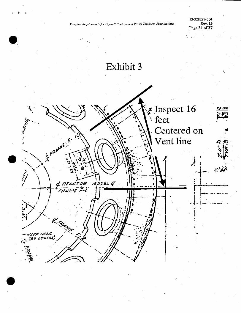
3.2.4.1.3 The entire surface fiom the base of the sand bed . region concrete floor (El 8’ 11 ”) to the top
. where the vessel rises into the 3” gap with the concrete (El. 12’ 3’3 shall visually (VT-1) be inspected. In the horizontal direction the inspection of one bay shall constitute all surfaces within 16 feet centered on the vent line (see Exhibit 3).
The inspection shall include a visual inspection of the caulking that was applied in 1992 at the interface between the former sandbed concrete floor and the drywell vessel (see Exhibit 4).
Video equipment or photographs shall be used to document the general condition of the coating. However, the resulting videos and photos shall be informational only. The actual inspection shall be direct visual and performed per ER-AA-335-018
3.2.4.1.4
3.2.4.1.5
.
3.2.4.2 Acceptance Criteria
3.2.4.2.1 Refer to Attachment 2 of procedure ER-AA- 335-01 8. All surface areas with flaking, chipping, blistering, peeling, pinpoint rusting, cracking, chalking and discoloration attributable to rust blooms shall be entered into the Corrective Action Program and evaluated by Engineering.

IS-328227-004 Funcrion Requiremenis for D w e l l Conrainmenr Vessel 7licbaess Examinations Rev. 13
Page 17 of 37
3.2.4.2.2 The caulking at the base of the Drywell shall be fiee of chipping, peeling, and cracking. . Deviation shall be entered into the Corrective Action Program and evaluated by Engineering.
3.2.4.2.3
3.2.4.2.4
e 3.2.4.2.5
3.2.4,.2.6
Discoloration due to loose surface residue fiom surface wetting is acceptable so long as the coating below the residue has not degraded.
Minor flaking, chipping and peeling is acceptable. Minor flaking, chipping and peeling is defined as follows: isolated flaking, chipping and peeling where: the loose coating is less than a % square inch, is on the surface of the coating or caulking and does not penetrate to the base metal. The purpose of this exception is to allow minor physical damage that may have been caused by personnel moving around in the sand bed region and is not indicative of a coating or caulking breakdown.
Documentation of degraded areas shall include the location of the area (i.e. X inches fiom the vertical weld and Y inches fiom the downcomer penetration weld), the size of the area, and the specific degradation. A color picture of degraded areas shall be taken and provided to Engineering.
Document bays where ponding or standing water was observed.
3.2.4.3 Data Retention Inspections shall be documented for each bay on an NDE data sheet. The data sheets shall also include: the date and time of the examination, the examination method, the governing procedure, Examiner, and Reviewer.
3.2.4.4 Required
3.2.4.4.1
3.2.4.4.2
Support and Tools
Safety and Radcon support and coverage shall be provided as necessary.
The cavity in the former sandbed region is a confined space.
. 163-328227-004 Function Requirements for D y e 1 1 Conioinment Vessel 7hickness Examinations Rev. 13
Page 18 of 37
3.2.4.4.3 To provide access to the cavity in the former sandbed region, the scaffolding contractor must erect scaffolding up to each 20” man way in the Drywell Pedestal located in the Torus Room.
e
3.2.4.4.4 The field shall also remove the boron bags that fill each 20” man way.
3.2.4.4.5 After Inspections per section 3.2.3 and 3.2.4 are completed the station shall reinstall the boron bags and fill up each 20” man way and remove the scaffolding.
e
18-328227-004 Funciion Requiremenu for Drywell Conioinment Vessel Thickness Eraminotiom Rev. 13
Page 19 of 37
3.2.5 Sandbed Drain Line Inspection
3.2.5.1 Description
3.2.5.1.1
3.2.5.1.2
The former Sandbed cavity has five drain lines equally spaced around the sandbed (see exhibit 4). The purpose of these drains is to drain the cavity should water be introduced into the former sand bed cavity. The drains exit the Drywell Pedestal at the base of the Pedestal in the Torus Room.
Inspect these drains with a boroscope type video system to ensure they are not clogged. Inspections for each of the 5 specific drains shall be scheduled in the same refieling outage corresponding to the visual coating inspections (section 3.2.4); see table 4.
3.2.5.2 Acceptance Criteria Each drain line shall be free of blockage. Minor amounts of blockage (less than 15% of the cross sectional area) are acceptable. Lines with unacceptable blockage shall be entered in to the Corrective Action Program.
3.2.5.3 Data Retention Inspections shall be documented for each line on an NDE data sheet or in the PIMS Work Order including blockage less than 15%. The data sheets or PIMS Work Order shall also include: the date and time of the examination, the examination method, the governing procedure, Examiner, and Reviewer.
3.2.5.4 Required Support and Tools
3.2.5.4.1 Safety and Radcon support and coverage shall be provided as necessary.
The cavity in the former sandbed region is a confined space.
3.2.5.4.2

18-328227-004 Function Requiremenujor Drywell Containment Vessel i3ickness Eraminations Rev. 13
Page 20 of 37
e 3.2.6 Trench Visual and UT Examination
3.2.6.1 Description
3.2.6.1.1 In the mid 1980’s two trenches were cut out of the Drywell floor at elevation 10’ 3”. The purpose of these trenches was to allow UT inspection of the Drywell Vessel below the removed concrete. The inspection results were captured on NDE data sheets 86-049-047 and 86-049-056 (reference 2.7). These trenches were then filled.by the installation of a foam material (reference 2.1 1).
3.2.6.1.2 The base Drywell Vessel metal at the bottom of these two trenches shall be inspected as follows:
1) Care shall be taken not to damage the coating under the foam. Once the foam has been removed by an approved work order inspect the coating applied to the Vessel in accordance with ER-AA-335-018 and ASME Section XI subsection WE. Video equipment or photographs shall used to document the general condition of the coating. However, the resulting videos or photos shall be informational only. The actual inspection shall be direct visual and performed per ER-AA-335-018.
2) If the coating does not require repair, then perform UT inspection of the vessel through the coating per section 3.1.3.3. Select UT equipment that is capable of subtracting the coating thickness from the vessel wall thickness.
.
3) If the coating does require repair, then perform UT inspection of the vessel per section 3.1.3.3 once the coating has been removed for repair.
3.2.6.2 Acceptance Criteria
3.2.6.2.1 Visual Inspection Acceptance Criteria

. . z , I. . ’
IS-328221-004 Rev. 13
Page 21 of 37 . Funcrion Requirements for Dtywell Containment Vessel ntichess fiarninatwm
3.2.6.2.1.1 Refer to in attachment 2 of procedure ER-AA-335-03 8. All surface areas with flaking, chipping, blistering, peeling, pinpoint rusting, cracking, chalking, and discoloration attn’butable to rust blooms shall be entered into the Corrective Action Program and evaluated by Engineering.
@
3.2.6.2.1.2 Discoloration due to loose surface residue due to surface wetting on the foam is acceptable so long as the coating below the residue not degraded. A clean cloth shall clean off the loose surface residue.
3.2.6.2.1.3 Minor flaking, chipping and peeling is acceptable. Minor flaking, chipping and peeling is defined as follows: isolated flaking, chipping and peeling where: the loose coating is less than a ‘A square inch, is on the surface of the coating and does not penetrate to the base metal. The purpose of this exception is to allow minor physical damage that may have been caused by the removal of the foam and is not indicative of coating breakdown.
3.2.6.2.2 Vessel Thickness Acceptance Criteria
Readings less than 0.660” shall be entered.into the corrective action program and evaluated by Engineering. This acceptance criteria is based on the minimum recorded readings in 1987 (reference NDE data sheet 87-026-64), a 20 mil tolerance, and a 10 mil per year corrosion rate between 1987 and 1992. The acceptance criteria are not based on the minimum required code thickness, which is less than the above value.
3.2.6.3 Data Retention
3.2.6.3.1 Coating inspections shall be documented for each bay on an NDE data sheet. The data sheets shall also include: the date and time of the

: r *
IS-328227-004 Function Requirementsfor Drywell Conrainment Vessel bichess Examinations Rev. 13
Page 22 of 37 ..
m examination, the examination method, the governing procedure, Examiner, and Reviewer.
3.2.6.3.2 All UT readings values within each trench shall be documented on an NDE data sheet and .
formatted in a 7 column format similar to NDE data sheet 86-049-047 and 86-049-056 (please refer reference 2.7). The data sheet shall also include: the date and time of the examination, location of the core plugs, the examination method, the ID number of the equipment, the governing procedure, the ID number of the cal block, the location surface temperature, Examiner, Reviewer, Location ID in accordance with table 2.
3.2.6.4 Required Support and Tools
3.2.6.4.1 Safety and Radcon support and coverage shall be provided as necessary.
Remove the existing foam in the trench in accordance with an approved work order.
3.2.6.4.2
3.2.6.4.3 After the UT inspections are complete and the coating has been repaired, if applicable. Reinstall the foam in accordance with an approved work order and reference 2.1 1.

18-328227-004
e Function Requirements for Dtywell Containment Vessel lhfckne~s Examinatiom Rev. 13
Page 23 of 37
3.2.7 UT Inspection of Weld Joint at Elevation 23’ 6 7/8”
3.2.7.1 Background
At elevation 23’ 6 7/8” there is circumferential weld which joins the bottom spherical plates and the middle spherical plates. This weld joins plates that are 1.1 54” thick to the plates that are 0.770” thick. The edges of the 1.1 54 thick plates were fabricated with a taper to provide a smooth transition to the thinner plates.
3.2.7.2 Locations
3.2.7.2.1
3.2.7.2.2
Two separate locations shall be inspected per the requirements of section 3.2.7.3.
This weld joint is located at nearly the same elevation as the grating at elevation 23’ 6”. The I .I 54 thick plates are located below the grating. The “as built” drawings do not provide enough information to determine if there is enough clearance between the grating and the’side of the Drywell to allow NDE inspectors access to the lower plates. Therefore the two inspection locations will be selected by the NDE and Engineering, based on accessibility to the lower plate. To the extent possible the two inspection locations shall be selected within Bays 17,19, 13, or 15. These bays have historically experienced the most corrosion in the sandbed region. If necessary portions of the grating may have to be removed.
3.2.7.3 Inspection Requirements
3.2.7.3.1 Inspection of the 1.154’’ Plate
3.2.7.3.1 . I Dynamic UT inspections of the 1.154” thick plate shall be performed through the existing coating below the taper (see exhibit 6). Dynamically scan an area that is a nominally of 6” wide by 6” high. Record the average and maximum thickness. Also characterize and document all areas within this 6” by 6” area that are less than 0.96 inches thick.

IS-328227-004 Function Requiremenu for D w e l l Containmen; Vessel 7%ickness Examinations Rev. 13
Page 24 of 37
3.2.7.3.1.2 During this first inspection, m k k this e area with a low stress dye stamp so that repeat inspections can be performed in the future. This shall be accomplished by marking two comers of the 6” by 6” area.
3.2.7.3.1.3 If UT inspection (per the above paragraphs) of the 1.1 54” thick plate cannot be performed due to interference between the grating and the side of the drywell and if the grating cannot be easily removed, document the discrepancy into the Corrective Action Process for evaluation by Engineering.
3.2.7.3.2 Inspection of the 0.770” plate
3.2.7.3.2.1 Dynamic UT inspections of the 0.770” plate shall be performed through the existing coating above the weld. Dynamically scan an area that is a nominally of 6” wide by 6” high (see exhibit 6). Record the average and maximum thickness. Also characterize and document all areas within this 6” by 6” area that are less than 0.740 inches thick.
3.2.7.3.2.2 During the first inspection, mark this area with a low stress dye stamp so that repeat inspections can be performed in the future. This shall be accomplished by marking two corners of the 6” by 6’’ area.
3.2.7.3.3 Inspection of the Weld
3.2.7.3.3.1 Dynamic UT thickness inspection of the weld between the two 6” x 6” areas described above. Grind the weld crown flat if necessary. 100% of the weld area shall be inspected.
3.2.7.3.3.2 Review of the original constructjon drawings for the drywell vessel (CBI drawing 9-0971 sheet 4, details “Joint

18-328227-004 Function Requiremenujor D p e N Conrainmeni Vessel Thickness Examinnlions Rev. 13
Page 25 of 37
e R”, “Joint D” and “Joint E’? show that this weld was required to be flush. Therefore, most likely “Flat Top” process will not be required. However, it is possible the weld may have slight crown that was not completely flush. In this case the ylat Top process will simply remove the slight crown.
3.2.7.3.3.3 After the UT inspection is complete coat the exposed weld location with Versilube G351 grease or an approved alternative.
3.2.7.4 Acceptance Criteria
3.2.7.4.1 On the 0.770” thick plate and the weld, readings less than 0.655” shall be entered into the corrective action program and evaluated by Engineering. This acceptance criteria is based on the minimum recorded local readings found in the sphere during the 1991 random inspections and a 20 mil tolerance. This acceptance criteria is &based on the minimum required code thickness, which is less than the above value.
3.2.7.4.2 On the 1.154” thick plate readings less than 0.90” shall be entered into the corrective action program and evaluated by Engineering. This acceptance criteria is based on the minimum recorded local readings found in the sphere during the 1991 random inspections and a 20 mil tolerance. This acceptance criteria is not based on the minimum required code thickness, which is less than the above value.
3.2.7.5 Data Retention All readings and areas sizes for each location shall be documented on an NDE data sheet. In addition the location of the inspected area shall be clearly documented so that this same location can be inspection in the future. The data sheet shall also include: the date and time of the examination, the examination method, the ID number of the equipment, the governing procedure, the ID number of the cal block, the location surface temperature, Examiner, Reviewer, Location ID in accordance with table 3.
0

-- I , ’
IS-328227-004 Rev. 13
Page 26 of 37 Function Requiremenu for D y e 1 1 Conrainment Vessel lXickness Ekarninatiom
3.2.7.6 Required Support and Tools
3.2.7.6.1 Safety and Radcon support and coverage shall be provided as necessary.
3.2.7.6.2 The weld in the area must be ground flat prior to the inspection.
. .

Function Requiremenis for Drywell Containment Vessel 7hickness Examinationc IS-328227-004
Rev. 13 Page 27 of 37
3.2.8 UT Inspection of Weld Joint at Elevation 71’ 6”
3.2.8.1 Background At elevation 71’ 6” there is circumferential weld which joins the transition plates (referred to as the knuckle) between the cylinder and the sphere. This weld joins the knuckle plates, which are 2 5/S” thick to the cylinder plates, which are 0.64” thick. The edges of the 2 5/S” thick plates were fabricated with a 3 to 12 taper to provide a smooth transition to the thinner plates.
.
3.2.8.2 Locations/Scaffolding
3.2.8.2.1 Two separate locations shall be inspected per the requirements of section 3.2.8.3.
3.2.8.2.2 Inspection of this weld joint in two locations will require the erection of scaffolding fiom the drywell platform at elevation 47’. The inside of the Drywell at this elevation is very congested. Therefore the NDE, Engineering, and the trade that will erect the scaffolding will select the actual location. This will ensure that the inspection and scaffolding erection will be performed safely. To the extent possible the two inspection locations shall be selected within Bays 17,19, 13, or 15. These bays have historically experienced the most corrosion in the sandbed region. These are areas that are generally located above the 1-1,1-2, and 1-5 Drywell Cooling Units.
3.2.8.3 Inspection Requirements
3.2.8.3.1 Inspection of the 2 5/23” plate
3.2.8.3.1.1 Dynamic UT inspections of the 2 5/8” thick plate shall be performed through the existing coating below the taper on the plate (see exhibit 6). Dynamically scan an area that is a nominally of 6” wide by 6” high. Record the average and maximum thickness. Also characterize and document all areas within this 6” by 6” area that are less than 2.55 inches 0 thick.

Function Requirements for DtywelI Containment Vessel 17lickness Exominations IS-328227-004
Rev. 13 Page 28 of 37
3.2.8.3.1.2 During this first inspection, mark this area with a low stress dye stamp so that repeat inspections can be performed in the future. This shall be accomplished by marking two corners of the 6” by 6” area.
3.2.8.3.2 Inspection of the 0.64” plate
3.2.8.3.2.1 Dynamic UT inspections of the cylinder plate shall be performed through the ~
existing coating above the weld. Dynamically scan an area that is a nominally of 6” wide by 6” high. Record the average and maximum thickness, Also characterize and document all‘areas within this 6” by 6” area that are less than 0.585 inches thick.
3.2.8.3.2.2 During this first inspection, mark this area with a low stress dye stamp so that repeat inspections can be performed in the future. This shall be accomplished by marking two comers of the 6” by 6” area.

IS-328227-004 Function Requirements for D w e l l Containment Vessel ntickness fiaminarions Rev. 13
Page 29 of 37
0 ’ . 3.2.8;3.3 Inspection of the weld
3.2.8.3.3.1 Dynamic UT thickness inspection of the weld between the two 6” x 6” areas described above. Grind the weld crown flat if necessary. 100% of the weld area shall be inspected.
0
3.2.8.3.3.2 Review of the original construction drawings for the drywell vessel (CBI drawing 9-0971 sheet 4, details “Joint R”, “Joint D” and “Joint E”) show that this weld was required to be flush. Therefore, most likely “Flat Top” process will not be required. However, it is possible the weld may have slight crown that was not completely flush. In this case the Flat Top process will simply remove the slight crown.
3.2.8.3.3.3 After the UT inspection is complete coat the exposed weld location with Versilube G351 grease or an approved a1 temative.
3.2.8.4 Acceptance Criteria
3.2.8.4.1 On the cylinder plate (nominally 0.64”) and the weld, readings less than 0.56” shall be entered into the corrective action program and evaluated by Engineering. This acceptance criteria is based on minimum recorded readings found in the cylinder during the 3 991 random inspections and a 20 mil tolerance. This acceptance criteria is not based on the minimum required code thickness, which is less than the above value.
3.2.8.4.2 On the knuckle plate (nominally 2 9 8 ” ) readings less than 2.490” shall be entered into the corrective action program and evaluated by Engineering. This acceptance criteria is based on minimum recorded readings during the 1991 random inspections and a 20 mil tolerance. This acceptance criteria is not based on the minimum required code thickness, which is less than the above value.

IS-328227004 Function Requirements for D y e 1 1 Coniainment Vessel ?hiclotas Examinationr Rev. 13
Page 30 of 37
3.2.8.5 Data Retention All readings and areas sizes for each location shall be documented on an NDE data sheet. In addition the location of the inspected area shall be clearly documented so that this same location can be inspection in the future. The data sheet shall also include: the date
' and time of the examination, the examination method, the ID number of the equipment, the governing procedure, the ID number of the cal block, the location surface temperature, Examiner, Reviewer, Location ID in accordance with table 3.
3.2.8.6 Required Support and Tools
3.2.8.6.1 Safety and Radcon support and coverage shall be provided as necessary.
3.2.8.6.2 To provide access to this welded joint, the station must erect scaffolding from elevation 47'.
The weld in the area must be ground flat prior to the inspection.
3.2.8.6.3
3.2.8.6.4 Remove the scaffolding.
4 Quality Assurance
4.1 The following work shall be performed in accordance with the Exelon. Quality Assurance Program as follows:
4.1 . l UT and Visual Inspection shall be performed in accordance with approved procedures as described in section 3.1.2 and this specification.
UT inspections for sections 3.2.1, 3.2.2 and 3.2.3 shall be performed with a template that meets the dimensional requirements in exhibit 2 of this specification.
4.1.2
4.1.3 Resulting calculation(s) shall be developed and approved in accordance with Exelon approved procedures I

section 3.2.2 External UT
Table 4 - Inspection Schedule Inspection I 2006 I 2008 Internal UT I yes - all 1
Yes - all
I ~~
Inspection in upper locations elevations per I
Inspection of Locally Thin Areas in Bay 1 and 13 per section 3.2.3 Visual inspection of Former Sandbed coating per section 3.2 4
_section 3.2.1 Internal UT ' I ~ e s - a i l
I I
...-
locations
Yes - Bays 1, 5,7,9,13,15 11, and 17 and 19
Yes - Bays 3,
I Inspection in locations sandbed region per
- .-. Inspection of Sandbed drain lines per secti6n 3.2.5
Yes - drains Yes - drains corresponding cotresponding to Bay 1,5,7, to Bays 3,11,
Inspection in Trenches per section 3.2.6 Internal Visual Inspection in Trenches per .
locations
Yes -all locations
I 9,13,15 & 19 I & 17 Internal UT I ~ e s - a l l I
Weld joint at Elevation 23' 6 718" persection 3.2.7 UT Inspection of Weld Joint at Elevation 71' 6" per section 3.2.8
Ycs
section 3.2.6. , 1 UT Inspection of I Yes
VeJSell8ickness ExaminaHohs Page 31 of 37
2024 2026 2028 YeS - all locat ions
Yes - Bays 5, 7,9, 11, and

IS-328227-004 Rev. 13
Page 32 of 37 Function Requiremenu for Drywell Coniainmeni Vessel 7hickness Examinations
. .
Exhibit 1
Typical Orientation of Inspection Locations in the Sandbed Region
View - looking from inside the drywell
A . C D
Location IDS = Bay Number plus one of these letters: i.e. - cc11D’9

I S-32 8227-004 Function Requirements for D y v e l l Coniainmeni Vessel 7?&&iess Examinations Rev. 13
Page 33 of 37
Exhibit 2
Template shall be made of Stainless Steal, approximately 0.30 inches thick, with 49 holes centered on a 1 inch pattern. . \ 1-1 1” +/- 1/32” (T~P.) on 111 middle 6” by 1/4” row slit or cohjmn centered
I? Diameter of each hole shall between 9/16” and 5/8”.
1” (Typ.) a
IS-328227-004 Fundon Requirements for D y e 1 1 Containment Vessel l?rickness Eraminatwns Rev. 13
Page 34 of 37
Exhibit 3
. . i. . I ' i I
1 I-
I
' .
i I
. .

T ’* v
18-328227-004 Rev. 13
Page 35 of 37 Function Requirements for D w e l l Containment Vessel 7%iclmess Examinations
Exhibit 4
.... .. , . .. . .
. . . , ’.
I Inspect caulking at elevation 8’ 11” I

IS-328227-004 Function Requirementsfor DtyweN Coniainment Vessel ~ i c k n e s s Exominations Rev. 13
Page 36 of 37
Exhibit 5
Vessel Concrete Curb
row is 1” +/ - 1/16’’ from previous top row
Elevation View of Trenches
. .

- .. .- ,.<. t
IS-328227-004 Function Requirements for Dtywell Coniainmeni Vessel 7hickness Examinations Rev. 13
Page 37 of 37
e Exhibit 6
LOW Stress Dye Stamp to mark these corners 2
scan in accordance with section 3.2.7
Elevation 71) 6)’ or 23’ 6 7/8”
Perform Dynamic scan in accordance with section 3.2.7 and 3.2.8
weld per sections 3.2.7
Low Stress Dye Stamp to mark these corners
Elevation View