specification passive ntp in docsis 3.0 environment · 5.1 downstream rf characteristics ... 9...
TRANSCRIPT
ANGA 100 001 v1.01 (2016-07)
Specification for the passive Network Termination Point in DOCSIS 3.0 Environment
Network and Provisioning requirements
Version 1.01
ANGA Verband Deutscher Kabelnetzbetreiber e.V.
Nibelungenweg 2 D-50996 Köln Germany
Tel.: +49 221 390 900 17 Fax: +49 221 390 900 10
© 2016 ANGA Verband Deutscher Kabelnetzbetreiber e.V.
ANGA
ANGA 100 001 v1.01 (2016-07)2
Contents
Foreword ............................................................................................................................................................ 3
Modal verbs terminology ................................................................................................................................... 3
Introduction ........................................................................................................................................................ 4
1 Scope ........................................................................................................................................................ 4
2 References ................................................................................................................................................ 5 2.1 Normative references ......................................................................................................................................... 5 2.2 Informative references ....................................................................................................................................... 5
3 Definitions, symbols and abbreviations ................................................................................................... 6 3.1 Definitions ......................................................................................................................................................... 6 3.2 Abbreviations ..................................................................................................................................................... 7
4 RF Interface Connector ............................................................................................................................ 8 4.1 General ............................................................................................................................................................... 8 4.2 Environmental Profile ........................................................................................................................................ 8 4.3 Mechanical interface description for coaxial connector with socket centre contact .......................................... 8 4.4 Electrical Performance Characteristics .............................................................................................................. 9
5 Network RF Characteristics ................................................................................................................... 10 5.1 Downstream RF characteristics ....................................................................................................................... 10 5.1.1 Downstream Frequency Range .................................................................................................................. 10 5.1.2 Downstream RF performance .................................................................................................................... 10 5.2 Upstream RF characteristics ............................................................................................................................ 10 5.2.1 Upstream Frequency Range ....................................................................................................................... 10 5.2.2 Upstream RF performance ......................................................................................................................... 11
6 DOCSIS 3.0 Physical Interface Requirements ....................................................................................... 12
7 DOCSIS 3.0 MULPI Interface Requirements ........................................................................................ 19
8 DOCSIS 3.0 OSSI Interface Requirements ............................................................................................ 39
9 DOCSIS 3.0 SEC Interface Requirements ............................................................................................. 44
10 DOCSIS 3.0 CMCI Interface Requirements .......................................................................................... 54
Annex 1 (informative): Implementation Advice .......................................................................................... 56
1.1 Coaxial cable assemblies ........................................................................................................................ 56
1.2 Cable Modem RF Port Characteristics ................................................................................................... 57
Annex 2 (informative): Change History ....................................................................................................... 57
History .............................................................................................................................................................. 58

ANGA
ANGA 100 001 v1.01 (2016-07)3
Foreword This interface specification is designed to describe the functioning of the interface at the passive Network Termination Point in DOCSIS 3.0 Environment according to Sec. 5 FTEG (German law on radio equipment and terminal equipment). It reflects the changes in law in force as of Aug 1, 2016 which aim to shift the net-work boundaries.
Modal verbs terminology In the present document "shall", "shall not", "should", "should not", "may", "need not", "will", "will not", "can" and "cannot" are to be used.
"must" and "must not" are NOT allowed in ANGA deliverables except when used in direct citation.
ANGA
ANGA 100 001 v1.01 (2016-07)4
Introduction Cable networks have advanced from a purely coaxial based distribution system. Incremental network changes made up of diverse technologies allow for bi-directional services while retaining most of the customer premises installation. Changes to the German Telekommunikationsgesetz (TKG) allow customers to become part of the neighbourhoods’ network backbone. They may establish connections to the Cable Modem Termination System (CMTS) and supporting systems as long as the customer devices are attached to the passive Network Termination Point in a technically correct manner. Hence, only cable modems conforming to the OPERATOR defined interface specification and operational val-ues shall be attached to the pNTP.
1 Scope This interface specification describes and specifies the main characteristics of the dedicated data interface in the OPERATOR cable network at the user’s coaxial passive network termination point. This interface specification describes the typical limits or values within which the network characteristics can be expected to remain for networks that are built according to OPERATOR specifications at installation time.
The interface specification does not apply under abnormal operating conditions such as:
- operating conditions arising as a result of operating services other than DOCSIS 3.0 over the dedicated data in-terface (see e.g. PHY, MULPI, CMCI, OSSI, SEC and EN 60728-1).
- operating conditions arising as a result of a fault, maintenance and construction work or to minimize the extend of interruption of service.
- operating conditions arising as a result of force majeure or third party interference. - operating conditions arising as a result of test signal injection governed by regulation. - In case of non-compliance of a network user’s installation or non-compliance of equipment with the relevant
standards or non-compliance with the technical requirements for connection, established either by this interface specification or the public authorities including the relevant limits for electromagnetic compatibility.
The characteristics given in this interface specification are intended to be used to derive and specify requirements for equipment such as coaxial cables and cable modems to connect them to the dedicated data interface. The values in this interface specification take precedence over requirements in equipment product standards and in installation standards. The given characteristics are not intended to be used as electromagnetic compatibility levels or user emission limits in the OPERATOR network.
This interface specification may be changed at any time to reflect changes made to the network as required by Sec. 5 Para. 2 FTEG. Anyone using this specification is requested to regularly check for the newest version at the respective website as published by BNetzA. This standard may be superseded in total or in part by the terms of a contract between an individual user of this specification and the OPERATOR.
ANGA
ANGA 100 001 v1.01 (2016-07)5
2 References
2.1 Normative references
[1] ETSI ETS 300 019-1-3 “Equipment Engineering (EE); Environmental conditions and envi-ronmental tests for telecommunications equipment; Part 1-3: Classification of environ-mental conditions; Stationary use at weather protected locations”
[2] Deutsche Bundespost FTZ 1 R 8 – 15, Dezember 1985 “Technische und betriebliche Be-dingungen für die Überlassung von Hauptanschlüssen, posteigenen Leitungen und Stromwegen sowie Direkt-Datenverbindungen (und für die Zulassung amtsberechtigter privater Leitungen) Teil 15: Breitbandanschlüsse”
[3] IEC 61169-24:2001 “Radio-frequency connectors – Part 24: Sectional specification – Ra-dio frequency coaxial connectors with screw coupling, typically for use in 75 ohm cable distribution systems (type F)”
[4] IEC 61169-24:2009 “Radio-frequency connectors – Part 24: Sectional specification – Ra-dio frequency coaxial connectors with screw coupling, typically for use in 75 Ω cable net-works (type F)”
[5] SCTE 02 2015 “Specification for “F” Port, Female, Indoor
[6] DIN EN 60728-1:2008 “Cable networks for television signals, sound signals and interac-tive services - Part 1: System performance of forward paths; German version EN 60728-1:2008”
[7] DIN EN 60728-4 “Cable networks for television signals, sound signals and interactive services - Part 4: Passive wideband equipment for coaxial cable networks (IEC 60728-4); German version EN 60728-4”
[8] DIN EN 60728-11:2005 “Cable networks for television signals, sound signals and interac-tive services - Part 11: Safety; German version EN 60728-11:2005”
[9] DIN EN 60728-11:2011 “Cable networks for television signals, sound signals and interac-tive services - Part 11: Safety; German version EN 60728-11:2010”
[10] CableLabs “Data Over Cable Service Interface Specifications, DOCSIS 3.0 Physical Lay-er Specification CM-SP-PHYv3.0-I12-150305”
[11] CableLabs “Data Over Cable Service Interface Specifications, DOCSIS 3.0 MAC and Upper Layer Protocols Interface Specification CM-SP-MULPIv3.0-I29-151210”
[12] CableLabs “Data Over Cable Service Interface Specifications, DOCSIS 3.0 Operations Support System Interface Specification CM-SP-OSSIv3.0-I28-151210”
[13] CableLabs “Data Over Cable Service Interface Specifications, DOCSIS 3.0 Security Specification CM-SP-SECv3.0-I15-130808”
[14] CableLabs “Data Over Cable Service Interface Specifications, DOCSIS 3.0 Cable Modem to Customer Premise Equipment Interface Specification CM-SP-CMCIv3.0-I02-140729”
[15] Excentis “EuroDOCSIS BPI+ Requirements: 2007”
2.2 Informative references [i.1] SchuTSEV, 13.05.2009 “Verordnung zum Schutz von öffentlichen Telekommunikations-
netzen und Sende- und Empfangsfunkanlagen, die in definierten Frequenzbereichen zu Sicherheitszwecken betrieben werden.”
ANGA
ANGA 100 001 v1.01 (2016-07)6
[i.2] ETSI ES 201 488 “Data Over Cable Service Interface Specifications (DOCSIS); Radio Frequency Interface Specifications”
[i.3] EN 60966-2-6:2009 “Radio frequency and coaxial cable assemblies - Part 2-6: Detail specification for cable assemblies for radio and TV receivers - Frequency range 0 MHz to 3000 MHz, IEC 61169-24 connectors (IEC 60966-2-6:2009)”
[i.4] IEC 60966-2-7:2015 “Radio frequency and coaxial cable asemblies - Part 2-7: Detail specification for cable assemblies for radio and TV receivers - Frequency range 0 MHz to 3 000 MHz, IEC 61169-47 connectors”
[i.5] EN 61169-47:2012 “Sectional specification for radio-frequency coaxial connectors with clamp coupling typically for use in 75 Ω cable networks (type F-Quick)”
[i.6] DIN EN 60728-1-1:2010 „Cable networks for television signals, sound signals and inter-active services – Part 1-1: RF cabling for two way home networks; German version EN 60728-1-1:2010“
[i.7] EN 50289-3-9 “Communication cables - Specifications for test methods - Part 3-9: Me-chanical test methods; Bending tests”
3 Definitions, symbols and abbreviations
3.1 Definitions Cable Modem (CM): modulator-demodulator at subscriber locations intended for use in conveying data Communications on a cable television system Cable Modem Termination System (CMTS): cable modem termination system, located at the cable television system headend or distribution hub, which provides complementary functionality to the cable modem to enable data connectivity to a wide-area network Cable Network: coaxial-based broadband access network in the form of either an all-coax or Hybrid-Fibre/Coax (HFC) network Carrier Hum Modulation: peak-to-peak magnitude of the amplitude distortion relative to the RF carrier signal level due to the fundamental and low-order harmonics of the power-supply frequency Composite Second Order beat (CSO): peak of the average level of distortion products due to second-order non-linearity’s in cable system equipment Composite Triple Beat (CTB): peak of the average level of distortion components due to third-order non-linearity’s in cable system equipment customer: human being or organization that accesses the network in order to communicate via the services provided by the network downstream: in cable television, the direction of transmission from the headend to the subscriber dynamic range: ratio between the greatest signal power that can be transmitted over a multichannel analogue transmission system without exceeding distortion or other performance limits, and the least signal power that can be utilized without exceeding noise, error rate or other performance limits group delay: difference in transmission time between the highest and lowest of several frequencies through a device, circuit or system High Frequency (HF): Used in the present document to refer to the entire subsplit (5 MHz to 30 MHz) and extended subsplit (5 MHz to 65 MHz) band used in return channel communications over the cable television network
ANGA
ANGA 100 001 v1.01 (2016-07)7
hum modulation: undesired modulation of the television visual carrier by the fundamental or low-order harmonics of the power supply frequency, or other low-frequency disturbances Hybrid Fibre/Coax (HFC) system: broadband bidirectional shared-media transmission system using fibre trunks between the headend and the fibre nodes, and coaxial distribution from the fibre nodes to the customer locations impulse noise: noise characterized by non-overlapping transient disturbances layer: subdivision of the Open System Interconnection (OSI) architecture, constituted by subsystems of the same rank micro-reflections: echoes in the forward transmission path due to departures from ideal amplitude and phase characteristics mid split: frequency division scheme that allows bi-directional traffic on a single coaxial cable passive network termination point (pNTP): customer terminal with minimum optical/electrical spacing to the CMTS PHYsical (PHY) layer: layer 1 in the Open System Interconnection (OSI) architecture; the layer that provides services to transmit bits or groups of bits over a transmission link between open systems and which entails electrical, mechanical and handshaking procedures Quadrature Amplitude Modulation (QAM): method of modulating digital signals onto a radio-frequency carrier signal involving both amplitude and phase coding Radio Frequency (RF): in cable television systems, this refers to electromagnetic signals in the range 5 MHz to 1 GHz return loss (RL): parameter describing the attenuation of a guided wave signal (e.g. via a coaxial ca-ble) returned to a source by a device or medium resulting from reflections of the signal generated by the source terminal: equipment connected to a telecommunication network to provide access to one or more spe-cific services
3.2 Abbreviations BER Bit Error Rate C/N or CNR Carrier-to-Noise Ratio CENELEC European Commitee for Electrotechnical Standardization CM Cable Modem CPE Customer Premise Equipment CSO Composite Second Order beat CTB Composite Triple Beat DIN Deutsches Institut für Normung DOCSIS Data Over Cable Service Interface Specifications ETSI European Telecommunications Standards Institute FM Frequency Modulation HF High Frequency HFC Hybrid-Fibre/Coax IEC International Electrotechnical Commission ISO International Organization for Standardization MER Modulation Error Ratio PER Packet Error Rate QAM Quadrature Amplitude Modulation QPSK Quadrature Phase-Shift Keying RF Radio Frequency pNTP passive Network Termination Point
ANGA
ANGA 100 001 v1.01 (2016-07)8
TI Terminal Input SNR Signal to Noise Ratio
4 RF Interface Connector
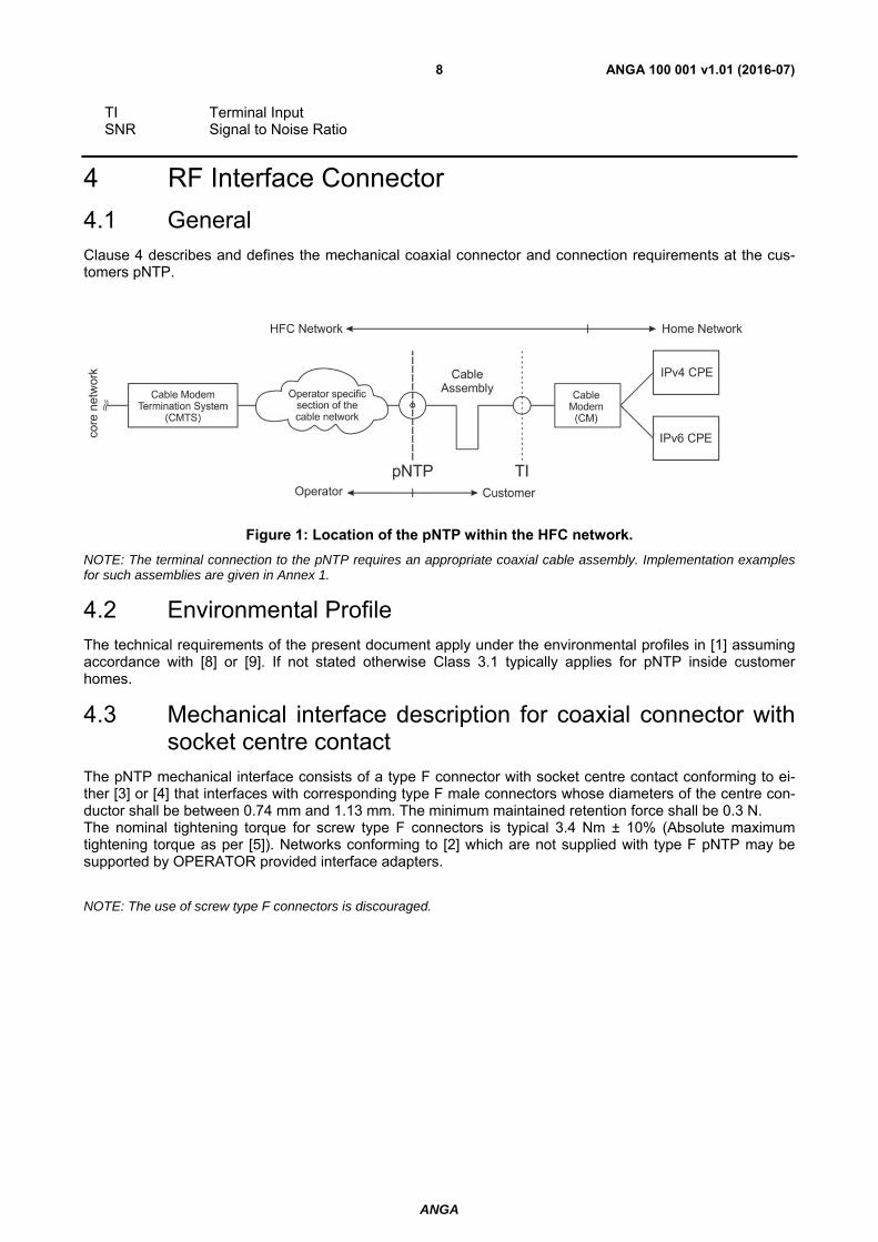
4.1 General Clause 4 describes and defines the mechanical coaxial connector and connection requirements at the cus-tomers pNTP.
Figure 1: Location of the pNTP within the HFC network.
NOTE: The terminal connection to the pNTP requires an appropriate coaxial cable assembly. Implementation examples for such assemblies are given in Annex 1.
4.2 Environmental Profile
The technical requirements of the present document apply under the environmental profiles in [1] assuming accordance with [8] or [9]. If not stated otherwise Class 3.1 typically applies for pNTP inside customer homes.
4.3 Mechanical interface description for coaxial connector with socket centre contact
The pNTP mechanical interface consists of a type F connector with socket centre contact conforming to ei-ther [3] or [4] that interfaces with corresponding type F male connectors whose diameters of the centre con-ductor shall be between 0.74 mm and 1.13 mm. The minimum maintained retention force shall be 0.3 N. The nominal tightening torque for screw type F connectors is typical 3.4 Nm ± 10% (Absolute maximum tightening torque as per [5]). Networks conforming to [2] which are not supplied with type F pNTP may be supported by OPERATOR provided interface adapters.
NOTE: The use of screw type F connectors is discouraged.

ANGA
ANGA 100 001 v1.01 (2016-07)9
Figure 2: Type F connector with socket centre contact
Table 1: Mechanical Interface Dimensions
Dimension NominalA accepts 0.74 – 1.13 mm B-H according to [3] or [4] NOTE: The mechanical Interface is compatible with [i.5]
4.4 Electrical Performance Characteristics
This clause describes the nominal electrical performance characteristics in the frequency range from DC to 862 MHz.
The nominal system impedance is 75 Ω. This impedance is the reference impedance for all passive coaxial components such as cables, connectors and wall outlets in the specified frequency range. Impedance mis-match results in a lower return loss.
The DC contact resistance of the centre conductor junction of the type F connector with socket centre con-tact to male F centre conductor shall be less than 25 mΩ and the DC contact resistance shall be less than 10 mΩ.
NOTE: The resulting contact resistance when using copper-clad steel conductors is typically greater than 10 mΩ.
The minimum nominal return loss of the pNTP is given in the table below.
Table 2: Minimum Return Loss
Frequency Range [MHz] Nominal1.
5 to 47 ≥ 14 dB 47 to 862 14 dB – 1.5 dB/octave, ≥ 10 dB1. see [7]
ANGA
ANGA 100 001 v1.01 (2016-07)10
5 Network RF Characteristics This clause describes and defines the RF parameters and requirements at the customer’s pNTP.
5.1 Downstream RF characteristics
5.1.1 Downstream Frequency Range
The channel spacing takes into account downstream path channel bandwidths of 7 MHz (analogue TV only) and 8 MHz. During the course of the migration to digital services analogue channels according to ITU-R 470 BT (B, G PAL) can be replaced by digital channels resulting in a uniform channel spacing of 8 MHz from 110 MHz to 862 MHz. DOCSIS 3.0 channels are grouped into blocks of 4, 8 or more.
The DOCSIS downstream frequency range according to [10], B.6.3.2 shall be 112 to 858 MHz (centre fre-quency, 112 to 1002 MHz optional).
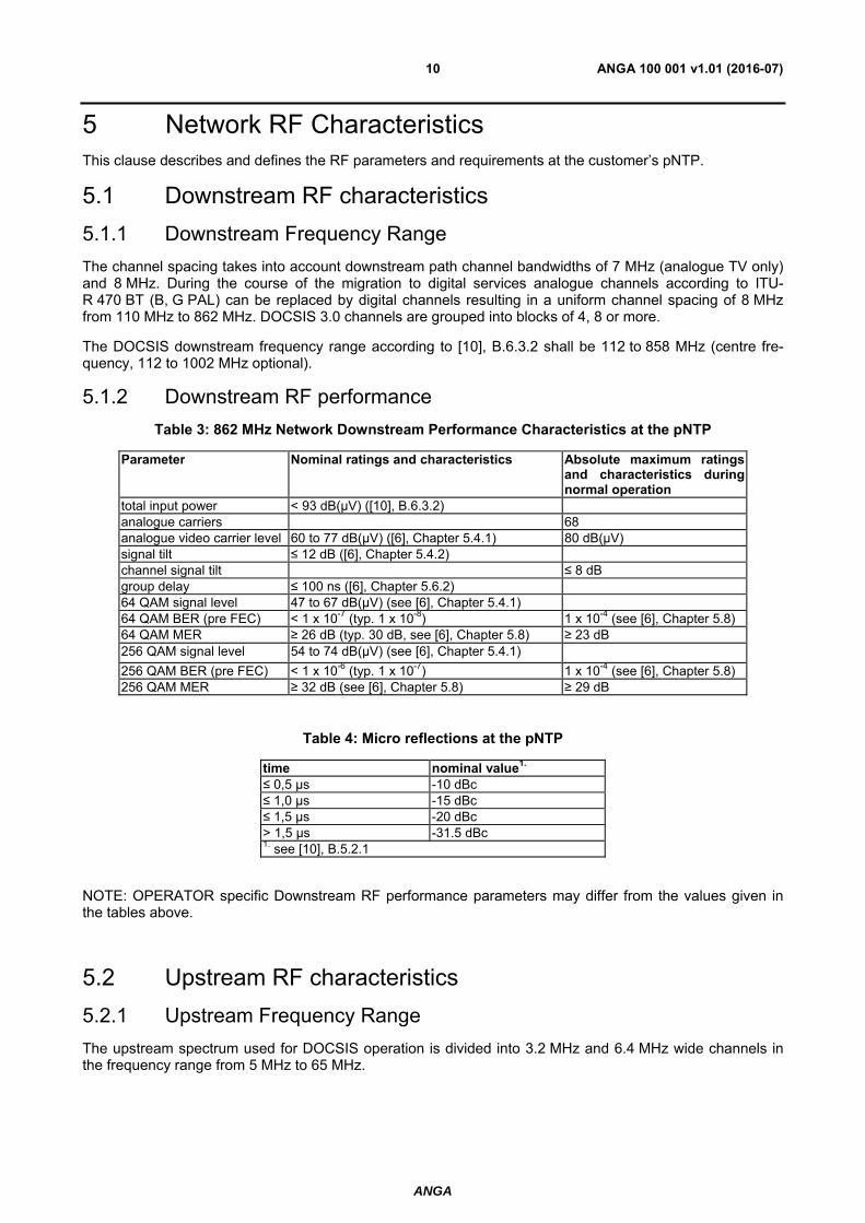
5.1.2 Downstream RF performance
Table 3: 862 MHz Network Downstream Performance Characteristics at the pNTP
Parameter Nominal ratings and characteristics Absolute maximum ratings and characteristics during normal operation
total input power < 93 dB(µV) ([10], B.6.3.2) analogue carriers 68 analogue video carrier level 60 to 77 dB(µV) ([6], Chapter 5.4.1) 80 dB(µV) signal tilt ≤ 12 dB ([6], Chapter 5.4.2) channel signal tilt ≤ 8 dB group delay ≤ 100 ns ([6], Chapter 5.6.2) 64 QAM signal level 47 to 67 dB(µV) (see [6], Chapter 5.4.1) 64 QAM BER (pre FEC) < 1 x 10⁻⁷ (typ. 1 x 10⁻⁸) 1 x 10⁻⁴ (see [6], Chapter 5.8)64 QAM MER ≥ 26 dB (typ. 30 dB, see [6], Chapter 5.8) ≥ 23 dB 256 QAM signal level 54 to 74 dB(µV) (see [6], Chapter 5.4.1)
256 QAM BER (pre FEC) < 1 x 10⁻⁶ (typ. 1 x 10⁻⁷) 1 x 10⁻⁴ (see [6], Chapter 5.8) 256 QAM MER ≥ 32 dB (see [6], Chapter 5.8) ≥ 29 dB
Table 4: Micro reflections at the pNTP
time nominal value1.
≤ 0,5 µs -10 dBc ≤ 1,0 µs -15 dBc ≤ 1,5 µs -20 dBc > 1,5 µs -31.5 dBc 1. see [10], B.5.2.1
NOTE: OPERATOR specific Downstream RF performance parameters may differ from the values given in the tables above.
5.2 Upstream RF characteristics
5.2.1 Upstream Frequency Range
The upstream spectrum used for DOCSIS operation is divided into 3.2 MHz and 6.4 MHz wide channels in the frequency range from 5 MHz to 65 MHz.
ANGA
ANGA 100 001 v1.01 (2016-07)11
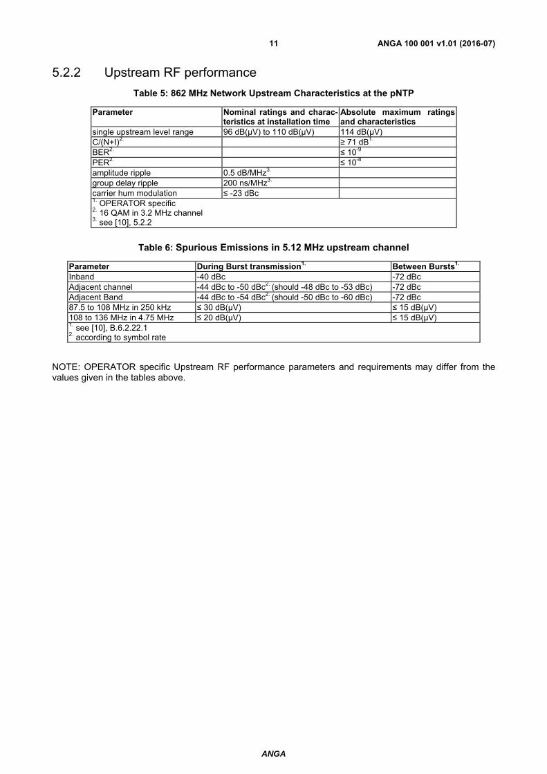
5.2.2 Upstream RF performance
Table 5: 862 MHz Network Upstream Characteristics at the pNTP
Parameter Nominal ratings and charac-teristics at installation time
Absolute maximum ratings and characteristics
single upstream level range 96 dB(µV) to 110 dB(µV) 114 dB(µV) C/(N+I)2. ≥ 71 dB1. BER2. ≤ 10-9 PER2. ≤ 10-8 amplitude ripple 0.5 dB/MHz3. group delay ripple 200 ns/MHz3. carrier hum modulation ≤ -23 dBc1. OPERATOR specific 2. 16 QAM in 3.2 MHz channel 3. see [10], 5.2.2
Table 6: Spurious Emissions in 5.12 MHz upstream channel
Parameter During Burst transmission1. Between Bursts1.
Inband -40 dBc -72 dBc Adjacent channel -44 dBc to -50 dBc2. (should -48 dBc to -53 dBc) -72 dBc Adjacent Band -44 dBc to -54 dBc2. (should -50 dBc to -60 dBc) -72 dBc 87.5 to 108 MHz in 250 kHz ≤ 30 dB(µV) ≤ 15 dB(µV) 108 to 136 MHz in 4.75 MHz ≤ 20 dB(µV) ≤ 15 dB(µV) 1. see [10], B.6.2.22.1 2. according to symbol rate
NOTE: OPERATOR specific Upstream RF performance parameters and requirements may differ from the values given in the tables above.
ANGA
ANGA 100 001 v1.01 (2016-07)12
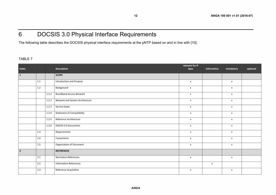
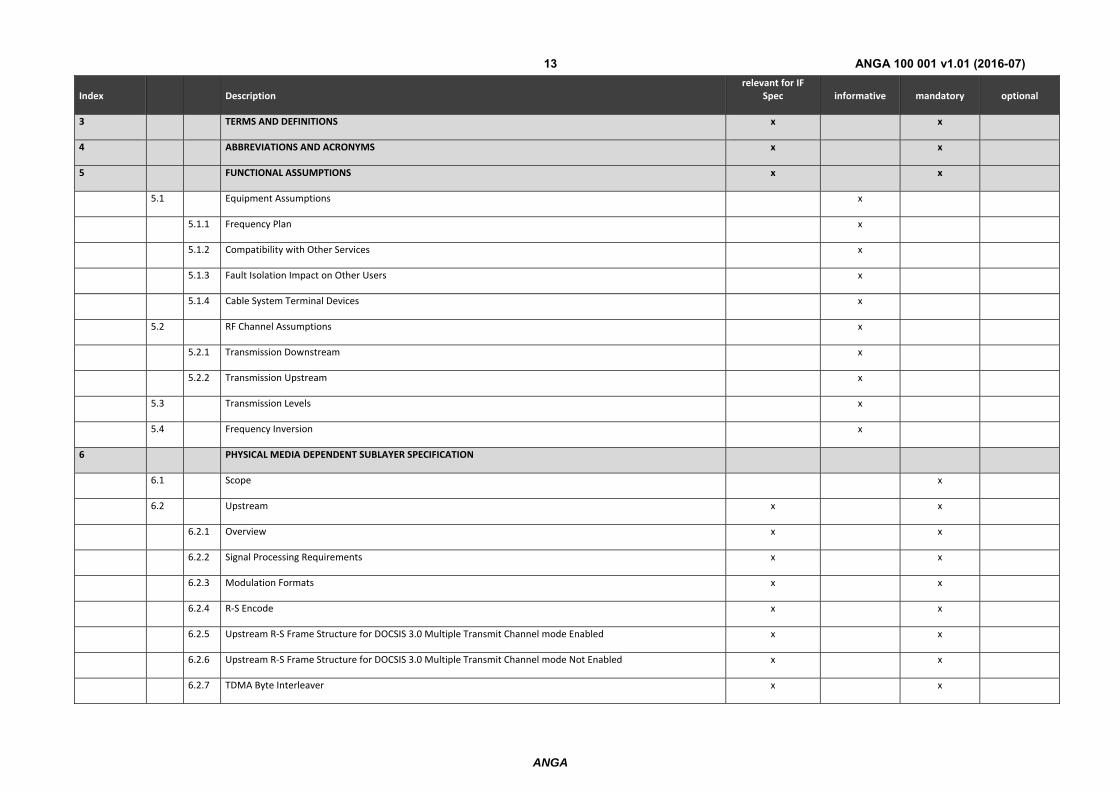
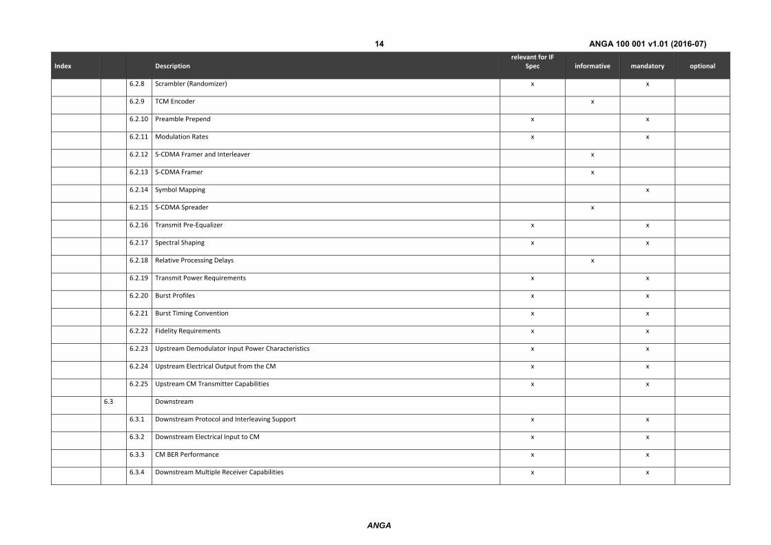
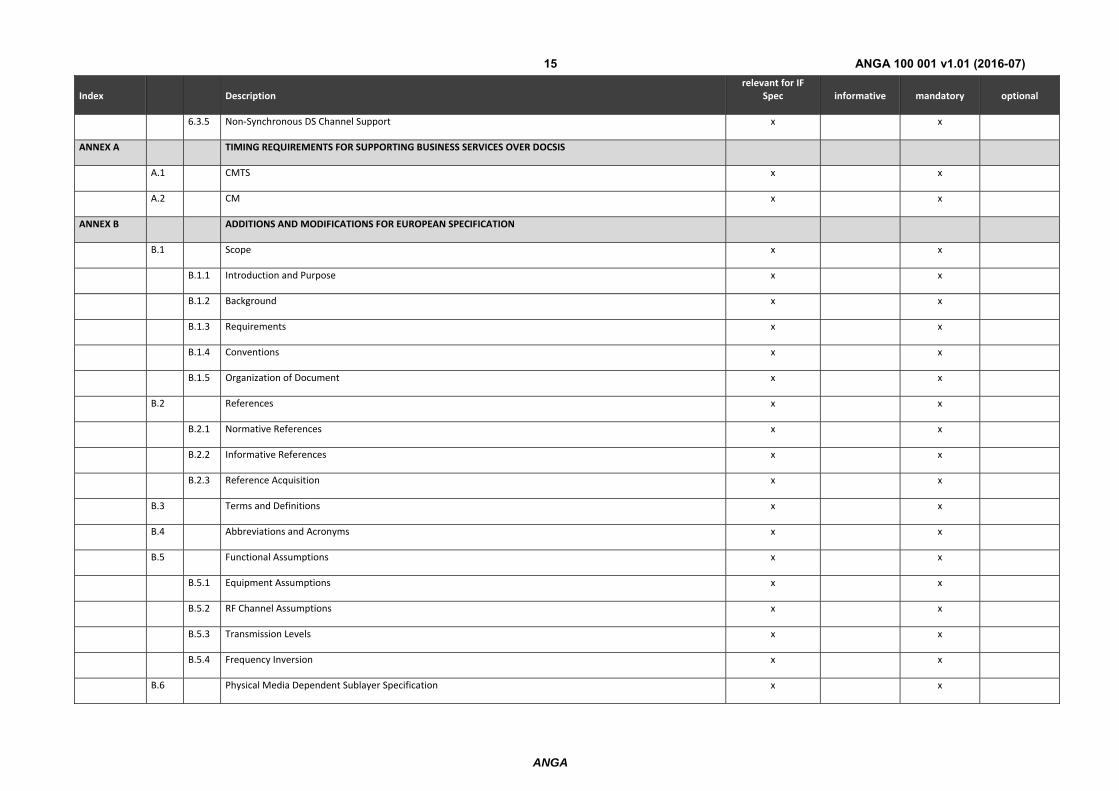
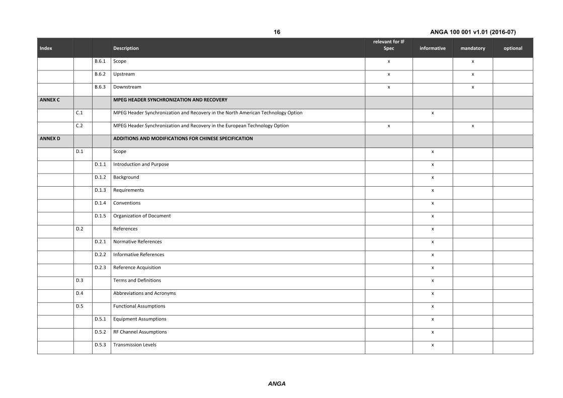
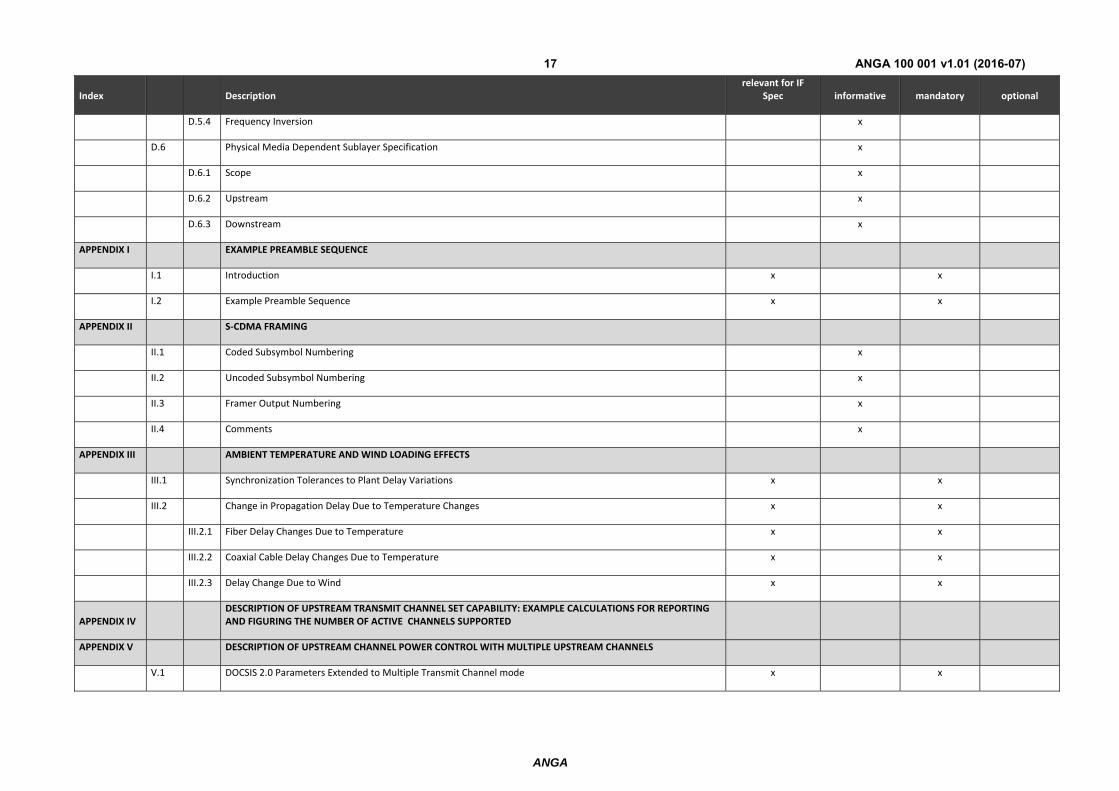
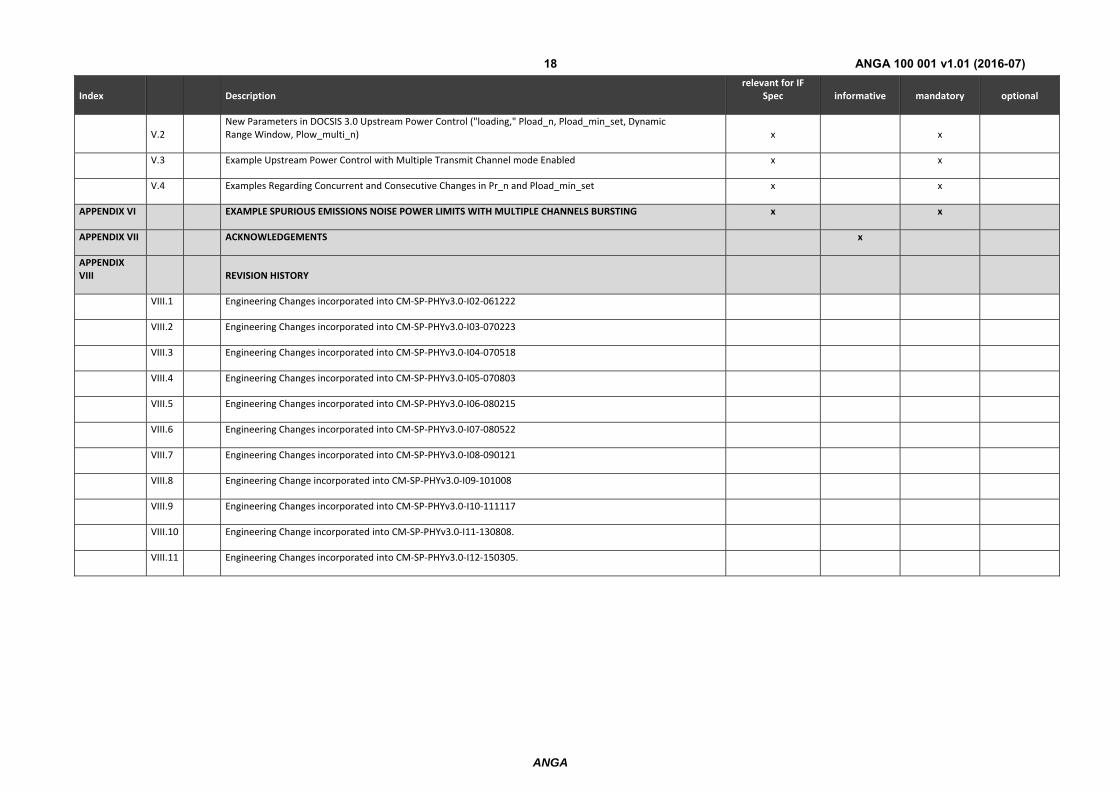
6 DOCSIS 3.0 Physical Interface Requirements The following table describes the DOCSIS physical interface requirements at the pNTP based on and in line with [10].
TABLE 7
Index Description relevant for IF
Spec informative mandatory optional
1 SCOPE
1.1 Introduction and Purpose x x
1.2 Background x x
1.2.1 Broadband Access Network x x
1.2.2 Network and System Architecture x x
1.2.3 Service Goals x x
1.2.4 Statement of Compatibility x x
1.2.5 Reference Architecture x x
1.2.6 DOCSIS 3.0 Documents x x
1.3 Requirements x x
1.4 Conventions x x
1.5 Organization of Document x x
2 REFERENCES
2.1 Normative References x x
2.2 Informative References x
2.3 Reference Acquisition x x
ANGA
ANGA 100 001 v1.01 (2016-07)13
Index Description relevant for IF
Spec informative mandatory optional
3 TERMS AND DEFINITIONS x x
4 ABBREVIATIONS AND ACRONYMS x x
5 FUNCTIONAL ASSUMPTIONS x x
5.1 Equipment Assumptions x
5.1.1 Frequency Plan x
5.1.2 Compatibility with Other Services x
5.1.3 Fault Isolation Impact on Other Users x
5.1.4 Cable System Terminal Devices x
5.2 RF Channel Assumptions x
5.2.1 Transmission Downstream x
5.2.2 Transmission Upstream x
5.3 Transmission Levels x
5.4 Frequency Inversion x
6 PHYSICAL MEDIA DEPENDENT SUBLAYER SPECIFICATION
6.1 Scope x
6.2 Upstream x x
6.2.1 Overview x x
6.2.2 Signal Processing Requirements x x
6.2.3 Modulation Formats x x
6.2.4 R‐S Encode x x
6.2.5 Upstream R‐S Frame Structure for DOCSIS 3.0 Multiple Transmit Channel mode Enabled x x
6.2.6 Upstream R‐S Frame Structure for DOCSIS 3.0 Multiple Transmit Channel mode Not Enabled x x
6.2.7 TDMA Byte Interleaver x x
ANGA
ANGA 100 001 v1.01 (2016-07)14
Index Description relevant for IF
Spec informative mandatory optional
6.2.8 Scrambler (Randomizer) x x
6.2.9 TCM Encoder x
6.2.10 Preamble Prepend x x
6.2.11 Modulation Rates x x
6.2.12 S‐CDMA Framer and Interleaver x
6.2.13 S‐CDMA Framer x
6.2.14 Symbol Mapping x
6.2.15 S‐CDMA Spreader x
6.2.16 Transmit Pre‐Equalizer x x
6.2.17 Spectral Shaping x x
6.2.18 Relative Processing Delays x
6.2.19 Transmit Power Requirements x x
6.2.20 Burst Profiles x x
6.2.21 Burst Timing Convention x x
6.2.22 Fidelity Requirements x x
6.2.23 Upstream Demodulator Input Power Characteristics x x
6.2.24 Upstream Electrical Output from the CM x x
6.2.25 Upstream CM Transmitter Capabilities x x
6.3 Downstream
6.3.1 Downstream Protocol and Interleaving Support x x
6.3.2 Downstream Electrical Input to CM x x
6.3.3 CM BER Performance x x
6.3.4 Downstream Multiple Receiver Capabilities x x
ANGA
ANGA 100 001 v1.01 (2016-07)15
Index Description relevant for IF
Spec informative mandatory optional
6.3.5 Non‐Synchronous DS Channel Support x x
ANNEX A TIMING REQUIREMENTS FOR SUPPORTING BUSINESS SERVICES OVER DOCSIS
A.1 CMTS x x
A.2 CM x x
ANNEX B ADDITIONS AND MODIFICATIONS FOR EUROPEAN SPECIFICATION
B.1 Scope x x
B.1.1 Introduction and Purpose x x
B.1.2 Background x x
B.1.3 Requirements x x
B.1.4 Conventions x x
B.1.5 Organization of Document x x
B.2 References x x
B.2.1 Normative References x x
B.2.2 Informative References x x
B.2.3 Reference Acquisition x x
B.3 Terms and Definitions x x
B.4 Abbreviations and Acronyms x x
B.5 Functional Assumptions x x
B.5.1 Equipment Assumptions x x
B.5.2 RF Channel Assumptions x x
B.5.3 Transmission Levels x x
B.5.4 Frequency Inversion x x
B.6 Physical Media Dependent Sublayer Specification x x
ANGA
ANGA 100 001 v1.01 (2016-07)16
Index Description relevant for IF
Spec informative mandatory optional
B.6.1 Scope x x
B.6.2 Upstream x x
B.6.3 Downstream x x
ANNEX C MPEG HEADER SYNCHRONIZATION AND RECOVERY
C.1 MPEG Header Synchronization and Recovery in the North American Technology Option x
C.2 MPEG Header Synchronization and Recovery in the European Technology Option x x
ANNEX D ADDITIONS AND MODIFICATIONS FOR CHINESE SPECIFICATION
D.1 Scope x
D.1.1 Introduction and Purpose x
D.1.2 Background x
D.1.3 Requirements x
D.1.4 Conventions x
D.1.5 Organization of Document x
D.2 References x
D.2.1 Normative References x
D.2.2 Informative References x
D.2.3 Reference Acquisition x
D.3 Terms and Definitions x
D.4 Abbreviations and Acronyms x
D.5 Functional Assumptions x
D.5.1 Equipment Assumptions x
D.5.2 RF Channel Assumptions x
D.5.3 Transmission Levels x
ANGA
ANGA 100 001 v1.01 (2016-07)17
Index Description relevant for IF
Spec informative mandatory optional
D.5.4 Frequency Inversion x
D.6 Physical Media Dependent Sublayer Specification x
D.6.1 Scope x
D.6.2 Upstream x
D.6.3 Downstream x
APPENDIX I EXAMPLE PREAMBLE SEQUENCE
I.1 Introduction x x
I.2 Example Preamble Sequence x x
APPENDIX II S‐CDMA FRAMING
II.1 Coded Subsymbol Numbering x
II.2 Uncoded Subsymbol Numbering x
II.3 Framer Output Numbering x
II.4 Comments x
APPENDIX III AMBIENT TEMPERATURE AND WIND LOADING EFFECTS
III.1 Synchronization Tolerances to Plant Delay Variations x x
III.2 Change in Propagation Delay Due to Temperature Changes x x
III.2.1 Fiber Delay Changes Due to Temperature x x
III.2.2 Coaxial Cable Delay Changes Due to Temperature x x
III.2.3 Delay Change Due to Wind x x
APPENDIX IV DESCRIPTION OF UPSTREAM TRANSMIT CHANNEL SET CAPABILITY: EXAMPLE CALCULATIONS FOR REPORTING AND FIGURING THE NUMBER OF ACTIVE CHANNELS SUPPORTED
APPENDIX V DESCRIPTION OF UPSTREAM CHANNEL POWER CONTROL WITH MULTIPLE UPSTREAM CHANNELS
V.1 DOCSIS 2.0 Parameters Extended to Multiple Transmit Channel mode x x
ANGA
ANGA 100 001 v1.01 (2016-07)18
Index Description relevant for IF
Spec informative mandatory optional
V.2 New Parameters in DOCSIS 3.0 Upstream Power Control ("loading," Pload_n, Pload_min_set, Dynamic Range Window, Plow_multi_n) x x
V.3 Example Upstream Power Control with Multiple Transmit Channel mode Enabled x x
V.4 Examples Regarding Concurrent and Consecutive Changes in Pr_n and Pload_min_set x x
APPENDIX VI EXAMPLE SPURIOUS EMISSIONS NOISE POWER LIMITS WITH MULTIPLE CHANNELS BURSTING x x
APPENDIX VII ACKNOWLEDGEMENTS x
APPENDIX VIII REVISION HISTORY
VIII.1 Engineering Changes incorporated into CM‐SP‐PHYv3.0‐I02‐061222
VIII.2 Engineering Changes incorporated into CM‐SP‐PHYv3.0‐I03‐070223
VIII.3 Engineering Changes incorporated into CM‐SP‐PHYv3.0‐I04‐070518
VIII.4 Engineering Changes incorporated into CM‐SP‐PHYv3.0‐I05‐070803
VIII.5 Engineering Changes incorporated into CM‐SP‐PHYv3.0‐I06‐080215
VIII.6 Engineering Changes incorporated into CM‐SP‐PHYv3.0‐I07‐080522
VIII.7 Engineering Changes incorporated into CM‐SP‐PHYv3.0‐I08‐090121
VIII.8 Engineering Change incorporated into CM‐SP‐PHYv3.0‐I09‐101008
VIII.9 Engineering Changes incorporated into CM‐SP‐PHYv3.0‐I10‐111117
VIII.10 Engineering Change incorporated into CM‐SP‐PHYv3.0‐I11‐130808.
VIII.11 Engineering Changes incorporated into CM‐SP‐PHYv3.0‐I12‐150305.
ANGA
ANGA 100 001 v1.01 (2016-07)19
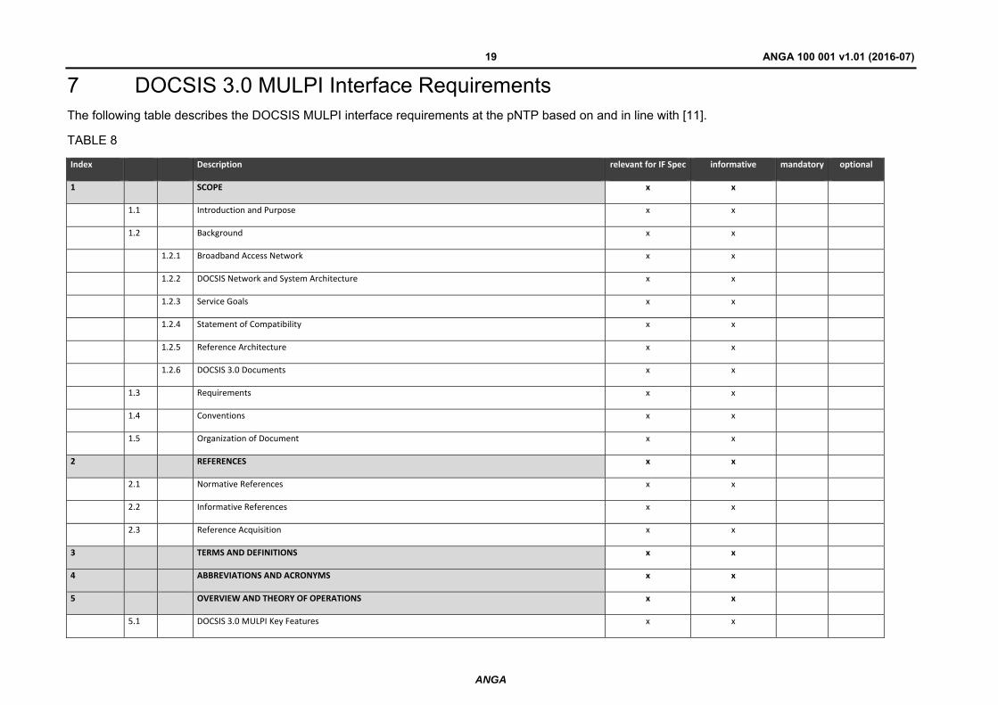
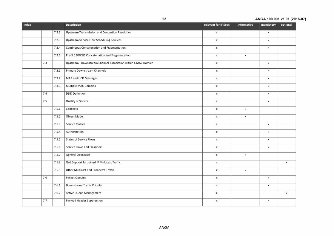
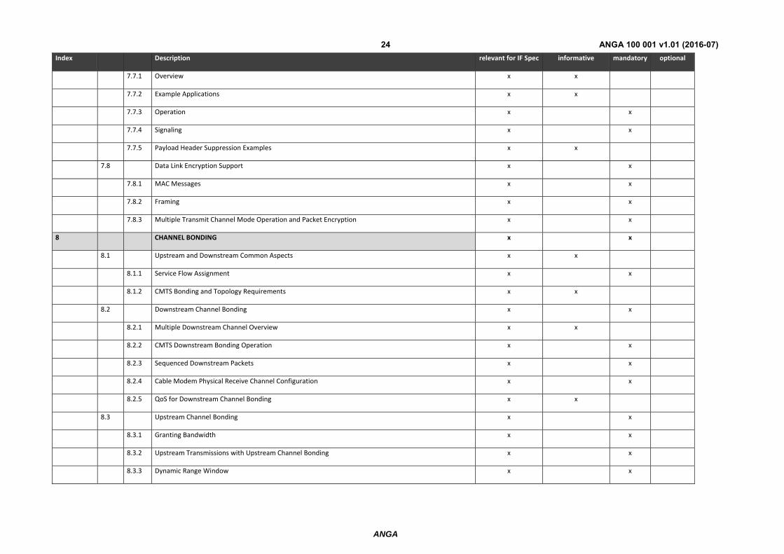
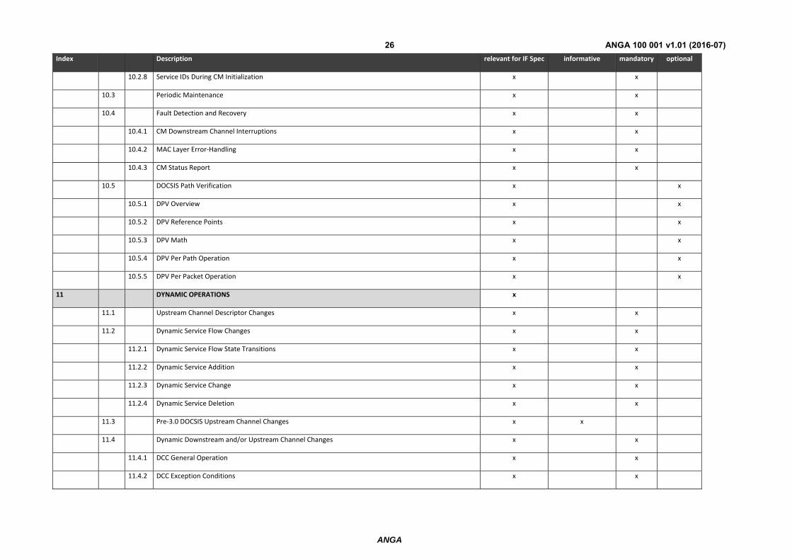
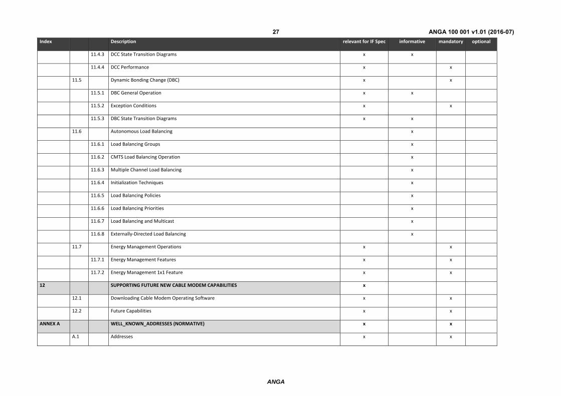
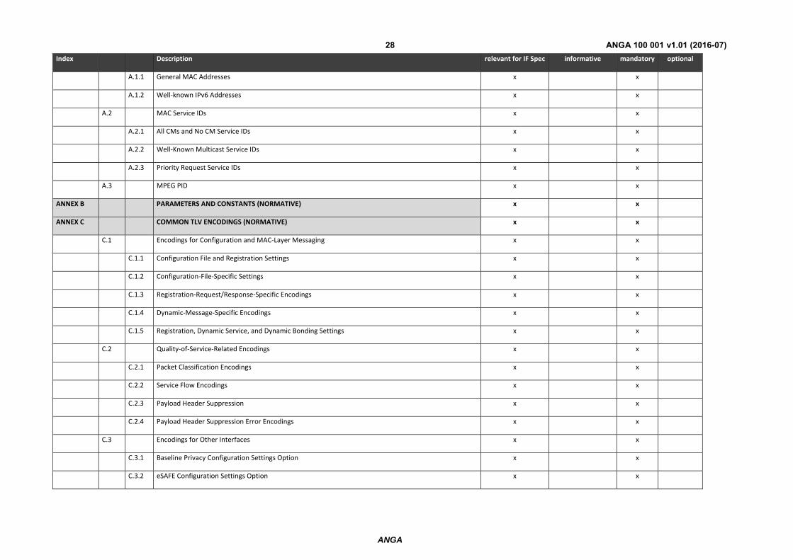
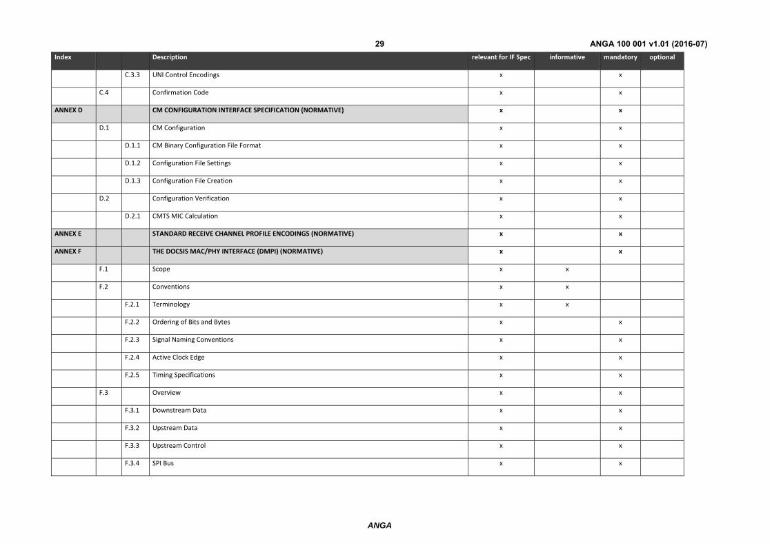
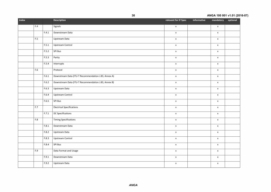
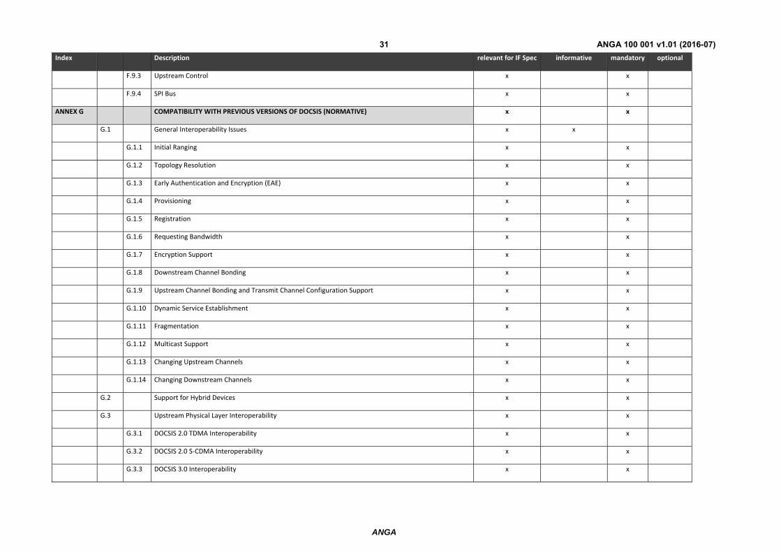
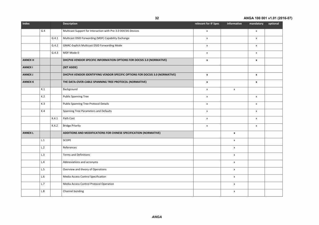
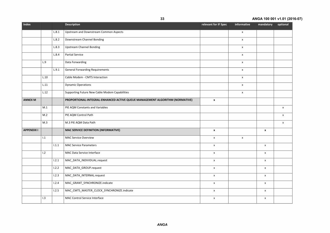
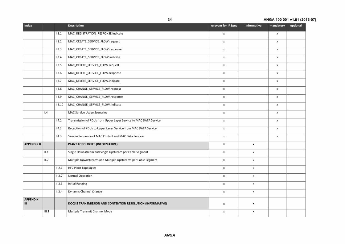
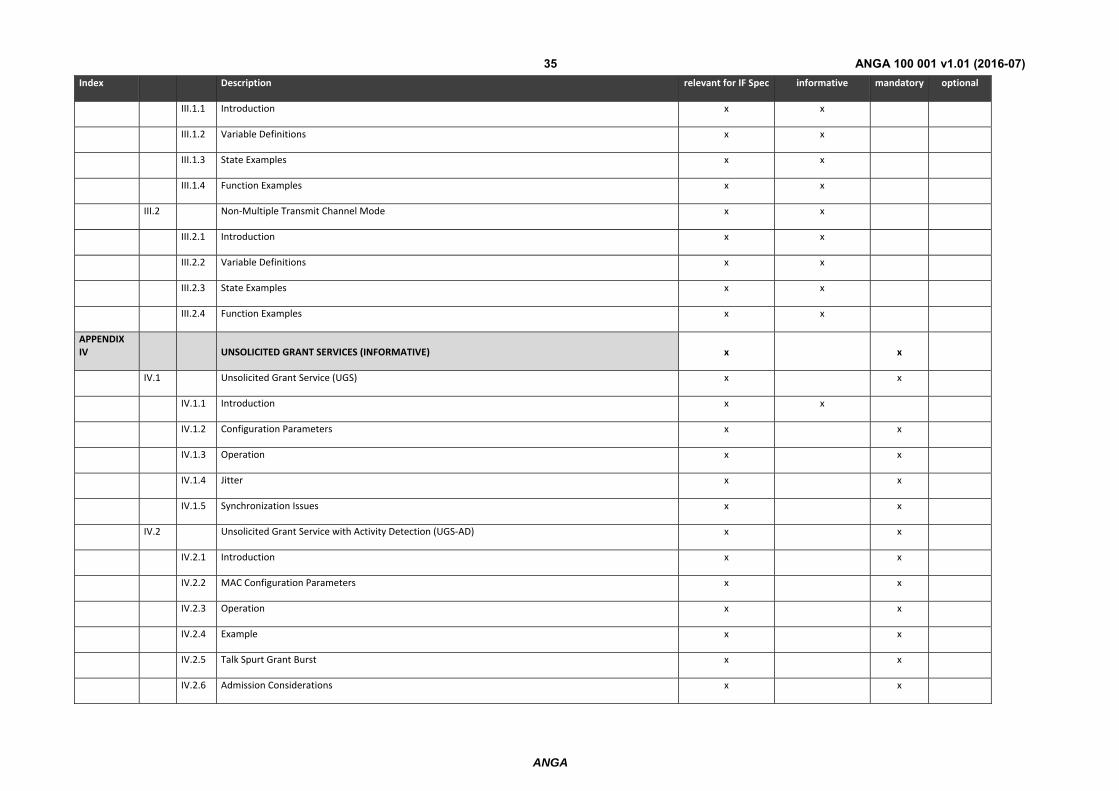
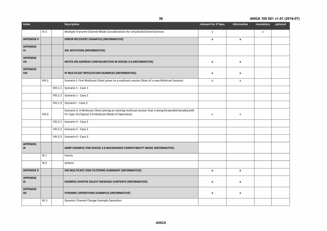
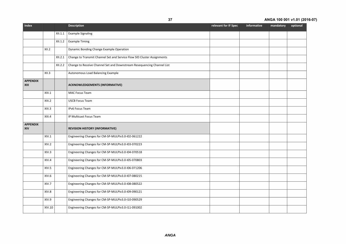
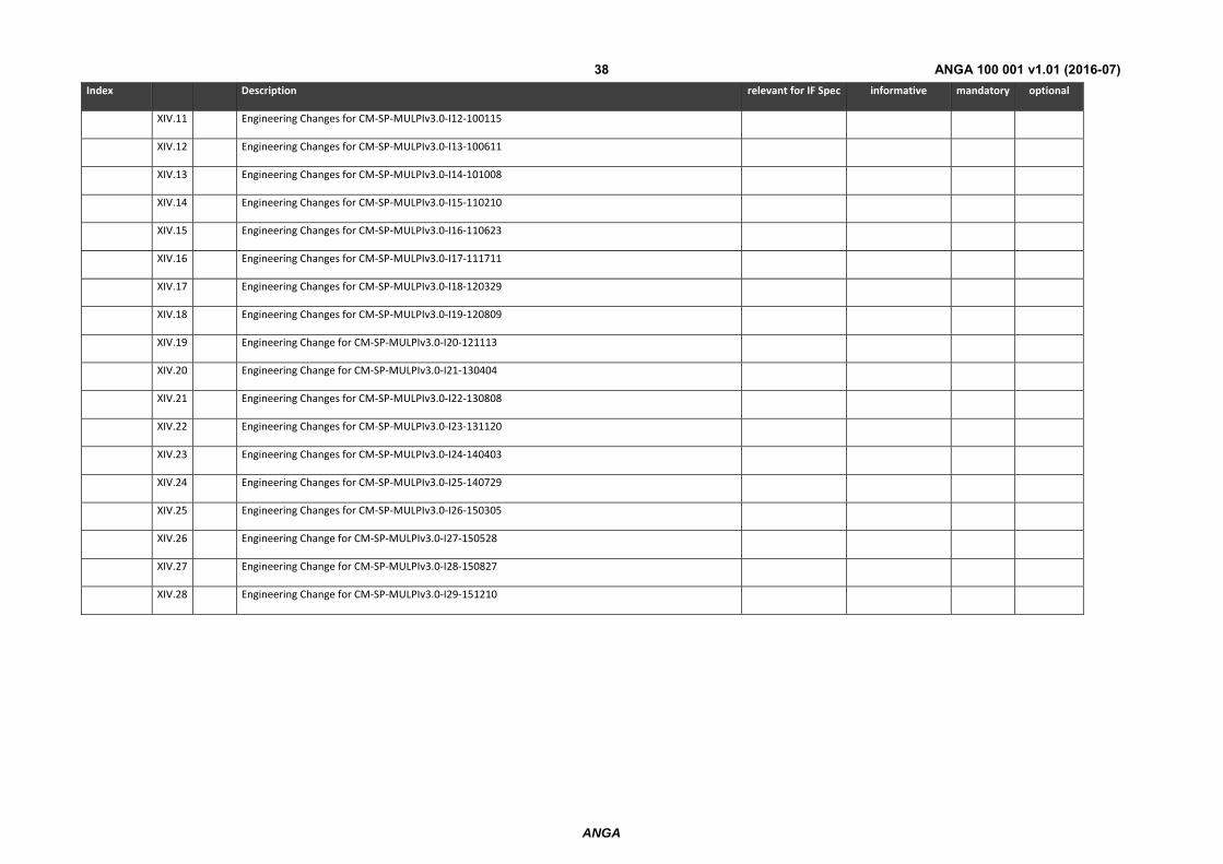
7 DOCSIS 3.0 MULPI Interface Requirements The following table describes the DOCSIS MULPI interface requirements at the pNTP based on and in line with [11].
TABLE 8
Index Description relevant for IF Spec informative mandatory optional
1 SCOPE x x
1.1 Introduction and Purpose x x
1.2 Background x x
1.2.1 Broadband Access Network x x
1.2.2 DOCSIS Network and System Architecture x x
1.2.3 Service Goals x x
1.2.4 Statement of Compatibility x x
1.2.5 Reference Architecture x x
1.2.6 DOCSIS 3.0 Documents x x
1.3 Requirements x x
1.4 Conventions x x
1.5 Organization of Document x x
2 REFERENCES x x
2.1 Normative References x x
2.2 Informative References x x
2.3 Reference Acquisition x x
3 TERMS AND DEFINITIONS x x
4 ABBREVIATIONS AND ACRONYMS x x
5 OVERVIEW AND THEORY OF OPERATIONS x x
5.1 DOCSIS 3.0 MULPI Key Features x x
ANGA
ANGA 100 001 v1.01 (2016-07)20
Index Description relevant for IF Spec informative mandatory optional
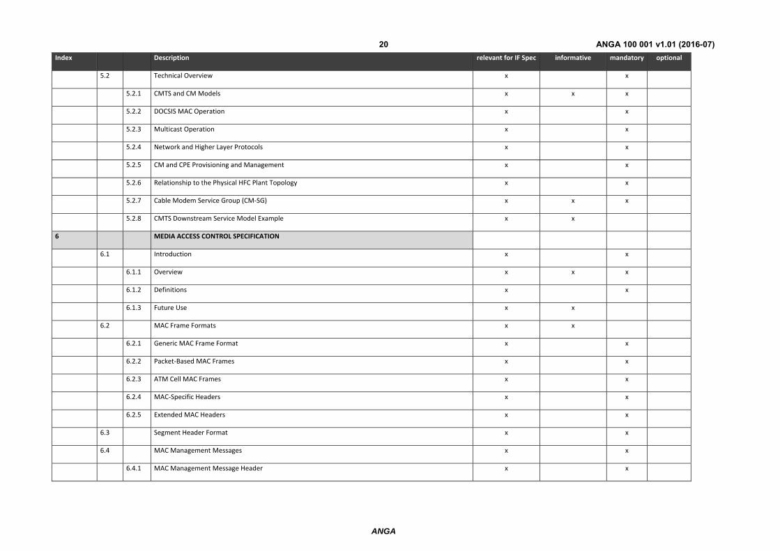
5.2 Technical Overview x x
5.2.1 CMTS and CM Models x x x
5.2.2 DOCSIS MAC Operation x x
5.2.3 Multicast Operation x x
5.2.4 Network and Higher Layer Protocols x x
5.2.5 CM and CPE Provisioning and Management x x
5.2.6 Relationship to the Physical HFC Plant Topology x x
5.2.7 Cable Modem Service Group (CM‐SG) x x x
5.2.8 CMTS Downstream Service Model Example x x
6 MEDIA ACCESS CONTROL SPECIFICATION
6.1 Introduction x x
6.1.1 Overview x x x
6.1.2 Definitions x x
6.1.3 Future Use x x
6.2 MAC Frame Formats x x
6.2.1 Generic MAC Frame Format x x
6.2.2 Packet‐Based MAC Frames x x
6.2.3 ATM Cell MAC Frames x x
6.2.4 MAC‐Specific Headers x x
6.2.5 Extended MAC Headers x x
6.3 Segment Header Format x x
6.4 MAC Management Messages x x
6.4.1 MAC Management Message Header x x
ANGA
ANGA 100 001 v1.01 (2016-07)21
Index Description relevant for IF Spec informative mandatory optional
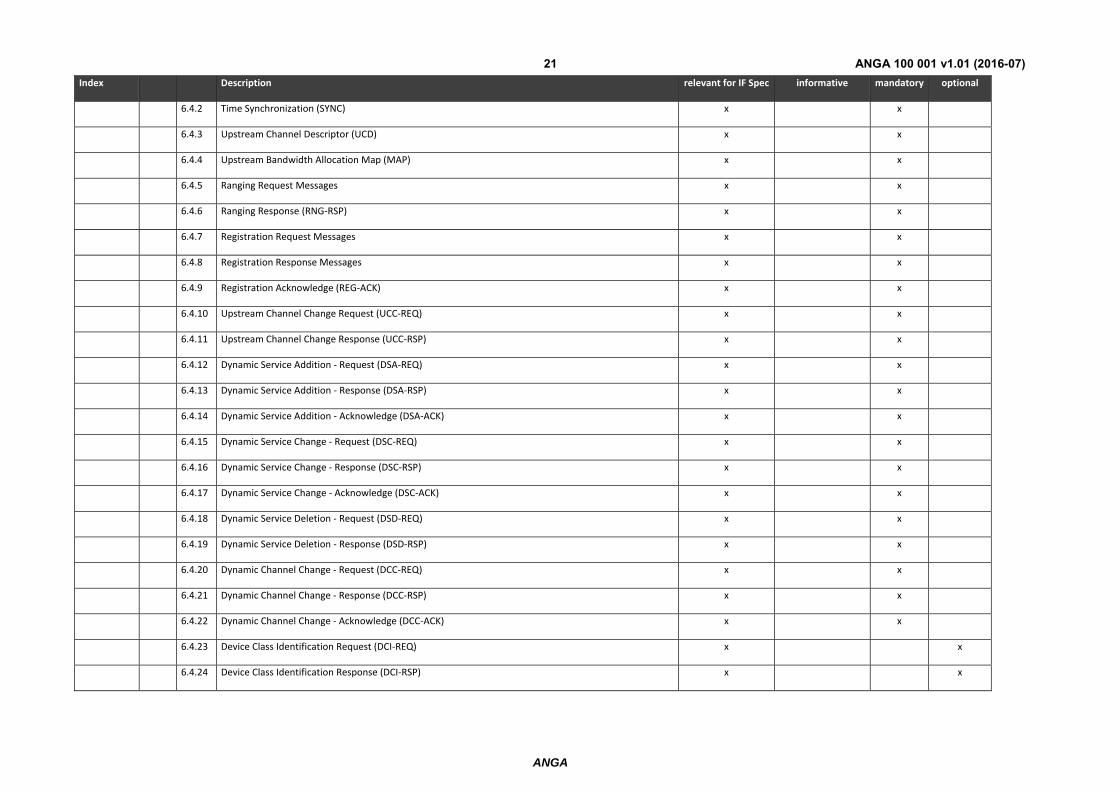
6.4.2 Time Synchronization (SYNC) x x
6.4.3 Upstream Channel Descriptor (UCD) x x
6.4.4 Upstream Bandwidth Allocation Map (MAP) x x
6.4.5 Ranging Request Messages x x
6.4.6 Ranging Response (RNG‐RSP) x x
6.4.7 Registration Request Messages x x
6.4.8 Registration Response Messages x x
6.4.9 Registration Acknowledge (REG‐ACK) x x
6.4.10 Upstream Channel Change Request (UCC‐REQ) x x
6.4.11 Upstream Channel Change Response (UCC‐RSP) x x
6.4.12 Dynamic Service Addition ‐ Request (DSA‐REQ) x x
6.4.13 Dynamic Service Addition ‐ Response (DSA‐RSP) x x
6.4.14 Dynamic Service Addition ‐ Acknowledge (DSA‐ACK) x x
6.4.15 Dynamic Service Change ‐ Request (DSC‐REQ) x x
6.4.16 Dynamic Service Change ‐ Response (DSC‐RSP) x x
6.4.17 Dynamic Service Change ‐ Acknowledge (DSC‐ACK) x x
6.4.18 Dynamic Service Deletion ‐ Request (DSD‐REQ) x x
6.4.19 Dynamic Service Deletion ‐ Response (DSD‐RSP) x x
6.4.20 Dynamic Channel Change ‐ Request (DCC‐REQ) x x
6.4.21 Dynamic Channel Change ‐ Response (DCC‐RSP) x x
6.4.22 Dynamic Channel Change ‐ Acknowledge (DCC‐ACK) x x
6.4.23 Device Class Identification Request (DCI‐REQ) x x
6.4.24 Device Class Identification Response (DCI‐RSP) x x
ANGA
ANGA 100 001 v1.01 (2016-07)22
Index Description relevant for IF Spec informative mandatory optional
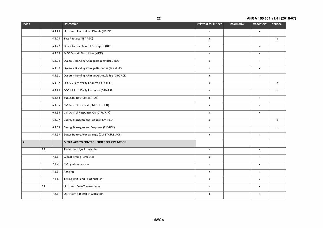
6.4.25 Upstream Transmitter Disable (UP‐DIS) x x
6.4.26 Test Request (TST‐REQ) x x
6.4.27 Downstream Channel Descriptor (DCD) x x
6.4.28 MAC Domain Descriptor (MDD) x x
6.4.29 Dynamic Bonding Change Request (DBC‐REQ) x x
6.4.30 Dynamic Bonding Change Response (DBC‐RSP) x x
6.4.31 Dynamic Bonding Change Acknowledge (DBC‐ACK) x x
6.4.32 DOCSIS Path Verify Request (DPV‐REQ) x x
6.4.33 DOCSIS Path Verify Response (DPV‐RSP) x x
6.4.34 Status Report (CM‐STATUS) x x
6.4.35 CM Control Request (CM‐CTRL‐REQ) x x
6.4.36 CM Control Response (CM‐CTRL‐RSP) x x
6.4.37 Energy Management Request (EM‐REQ) x x
6.4.38 Energy Management Response (EM‐RSP) x x
6.4.39 Status Report Acknowledge (CM‐STATUS‐ACK) x x
7 MEDIA ACCESS CONTROL PROTOCOL OPERATION
7.1 Timing and Synchronization x x
7.1.1 Global Timing Reference x x
7.1.2 CM Synchronization x x
7.1.3 Ranging x x
7.1.4 Timing Units and Relationships x x
7.2 Upstream Data Transmission x x
7.2.1 Upstream Bandwidth Allocation x x
ANGA
ANGA 100 001 v1.01 (2016-07)23
Index Description relevant for IF Spec informative mandatory optional
7.2.2 Upstream Transmission and Contention Resolution x x
7.2.3 Upstream Service Flow Scheduling Services x x
7.2.4 Continuous Concatenation and Fragmentation x x
7.2.5 Pre‐3.0 DOCSIS Concatenation and Fragmentation x x
7.3 Upstream ‐ Downstream Channel Association within a MAC Domain x x
7.3.1 Primary Downstream Channels x x
7.3.2 MAP and UCD Messages x x
7.3.3 Multiple MAC Domains x x
7.4 DSID Definition x x
7.5 Quality of Service x x
7.5.1 Concepts x x
7.5.2 Object Model x x
7.5.3 Service Classes x x
7.5.4 Authorization x x
7.5.5 States of Service Flows x x
7.5.6 Service Flows and Classifiers x x
7.5.7 General Operation x x
7.5.8 QoS Support for Joined IP Multicast Traffic x x
7.5.9 Other Multicast and Broadcast Traffic x x
7.6 Packet Queuing x x
7.6.1 Downstream Traffic Priority x x
7.6.2 Active Queue Management x x
7.7 Payload Header Suppression x x
ANGA
ANGA 100 001 v1.01 (2016-07)24
Index Description relevant for IF Spec informative mandatory optional
7.7.1 Overview x x
7.7.2 Example Applications x x
7.7.3 Operation x x
7.7.4 Signaling x x
7.7.5 Payload Header Suppression Examples x x
7.8 Data Link Encryption Support x x
7.8.1 MAC Messages x x
7.8.2 Framing x x
7.8.3 Multiple Transmit Channel Mode Operation and Packet Encryption x x
8 CHANNEL BONDING x x
8.1 Upstream and Downstream Common Aspects x x
8.1.1 Service Flow Assignment x x
8.1.2 CMTS Bonding and Topology Requirements x x
8.2 Downstream Channel Bonding x x
8.2.1 Multiple Downstream Channel Overview x x
8.2.2 CMTS Downstream Bonding Operation x x
8.2.3 Sequenced Downstream Packets x x
8.2.4 Cable Modem Physical Receive Channel Configuration x x
8.2.5 QoS for Downstream Channel Bonding x x
8.3 Upstream Channel Bonding x x
8.3.1 Granting Bandwidth x x
8.3.2 Upstream Transmissions with Upstream Channel Bonding x x
8.3.3 Dynamic Range Window x x

ANGA
ANGA 100 001 v1.01 (2016-07)25
Index Description relevant for IF Spec informative mandatory optional
8.4 Partial Service x x
9 DATA FORWARDING x x
9.1 General Forwarding Requirements x x
9.1.1 CMTS Forwarding Rules x x
9.1.2 CM Address Acquisition, Filtering and Forwarding Rules x x
9.2 Multicast Forwarding x x
9.2.1 Introduction x x
9.2.2 Downstream Multicast Forwarding x x
9.2.3 Downstream Multicast Traffic Encryption x x
9.2.4 Static Multicast Session Encodings x x
9.2.5 IGMP and MLD Support x x
9.2.6 Encrypted Multicast Downstream Forwarding Example x x
9.2.7 IP Multicast Join Authorization x x
10 CABLE MODEM ‐ CMTS INTERACTION x
10.1 CMTS Initialization x x
10.2 Cable Modem Initialization and Reinitialization x x
10.2.1 Scan for Downstream Channel x x
10.2.2 Continue Downstream Scanning x x
10.2.3 Service Group Discovery and Initial Ranging x x
10.2.4 Authentication x x
10.2.5 Establishing IP Connectivity x x
10.2.6 Registration with the CMTS x x
10.2.7 Baseline Privacy Initialization x x
ANGA
ANGA 100 001 v1.01 (2016-07)26
Index Description relevant for IF Spec informative mandatory optional
10.2.8 Service IDs During CM Initialization x x
10.3 Periodic Maintenance x x
10.4 Fault Detection and Recovery x x
10.4.1 CM Downstream Channel Interruptions x x
10.4.2 MAC Layer Error‐Handling x x
10.4.3 CM Status Report x x
10.5 DOCSIS Path Verification x x
10.5.1 DPV Overview x x
10.5.2 DPV Reference Points x x
10.5.3 DPV Math x x
10.5.4 DPV Per Path Operation x x
10.5.5 DPV Per Packet Operation x x
11 DYNAMIC OPERATIONS x
11.1 Upstream Channel Descriptor Changes x x
11.2 Dynamic Service Flow Changes x x
11.2.1 Dynamic Service Flow State Transitions x x
11.2.2 Dynamic Service Addition x x
11.2.3 Dynamic Service Change x x
11.2.4 Dynamic Service Deletion x x
11.3 Pre‐3.0 DOCSIS Upstream Channel Changes x x
11.4 Dynamic Downstream and/or Upstream Channel Changes x x
11.4.1 DCC General Operation x x
11.4.2 DCC Exception Conditions x x
ANGA
ANGA 100 001 v1.01 (2016-07)27
Index Description relevant for IF Spec informative mandatory optional
11.4.3 DCC State Transition Diagrams x x
11.4.4 DCC Performance x x
11.5 Dynamic Bonding Change (DBC) x x
11.5.1 DBC General Operation x x
11.5.2 Exception Conditions x x
11.5.3 DBC State Transition Diagrams x x
11.6 Autonomous Load Balancing x
11.6.1 Load Balancing Groups x
11.6.2 CMTS Load Balancing Operation x
11.6.3 Multiple Channel Load Balancing x
11.6.4 Initialization Techniques x
11.6.5 Load Balancing Policies x
11.6.6 Load Balancing Priorities x
11.6.7 Load Balancing and Multicast x
11.6.8 Externally‐Directed Load Balancing x
11.7 Energy Management Operations x x
11.7.1 Energy Management Features x x
11.7.2 Energy Management 1x1 Feature x x
12 SUPPORTING FUTURE NEW CABLE MODEM CAPABILITIES x
12.1 Downloading Cable Modem Operating Software x x
12.2 Future Capabilities x x
ANNEX A WELL_KNOWN_ADDRESSES (NORMATIVE) x x
A.1 Addresses x x
ANGA
ANGA 100 001 v1.01 (2016-07)28
Index Description relevant for IF Spec informative mandatory optional
A.1.1 General MAC Addresses x x
A.1.2 Well‐known IPv6 Addresses x x
A.2 MAC Service IDs x x
A.2.1 All CMs and No CM Service IDs x x
A.2.2 Well‐Known Multicast Service IDs x x
A.2.3 Priority Request Service IDs x x
A.3 MPEG PID x x
ANNEX B PARAMETERS AND CONSTANTS (NORMATIVE) x x
ANNEX C COMMON TLV ENCODINGS (NORMATIVE) x x
C.1 Encodings for Configuration and MAC‐Layer Messaging x x
C.1.1 Configuration File and Registration Settings x x
C.1.2 Configuration‐File‐Specific Settings x x
C.1.3 Registration‐Request/Response‐Specific Encodings x x
C.1.4 Dynamic‐Message‐Specific Encodings x x
C.1.5 Registration, Dynamic Service, and Dynamic Bonding Settings x x
C.2 Quality‐of‐Service‐Related Encodings x x
C.2.1 Packet Classification Encodings x x
C.2.2 Service Flow Encodings x x
C.2.3 Payload Header Suppression x x
C.2.4 Payload Header Suppression Error Encodings x x
C.3 Encodings for Other Interfaces x x
C.3.1 Baseline Privacy Configuration Settings Option x x
C.3.2 eSAFE Configuration Settings Option x x
ANGA
ANGA 100 001 v1.01 (2016-07)29
Index Description relevant for IF Spec informative mandatory optional
C.3.3 UNI Control Encodings x x
C.4 Confirmation Code x x
ANNEX D CM CONFIGURATION INTERFACE SPECIFICATION (NORMATIVE) x x
D.1 CM Configuration x x
D.1.1 CM Binary Configuration File Format x x
D.1.2 Configuration File Settings x x
D.1.3 Configuration File Creation x x
D.2 Configuration Verification x x
D.2.1 CMTS MIC Calculation x x
ANNEX E STANDARD RECEIVE CHANNEL PROFILE ENCODINGS (NORMATIVE) x x
ANNEX F THE DOCSIS MAC/PHY INTERFACE (DMPI) (NORMATIVE) x x
F.1 Scope x x
F.2 Conventions x x
F.2.1 Terminology x x
F.2.2 Ordering of Bits and Bytes x x
F.2.3 Signal Naming Conventions x x
F.2.4 Active Clock Edge x x
F.2.5 Timing Specifications x x
F.3 Overview x x
F.3.1 Downstream Data x x
F.3.2 Upstream Data x x
F.3.3 Upstream Control x x
F.3.4 SPI Bus x x
ANGA
ANGA 100 001 v1.01 (2016-07)30
Index Description relevant for IF Spec informative mandatory optional
F.4 Signals x x
F.4.1 Downstream Data x x
F.5 Upstream Data x x
F.5.1 Upstream Control x x
F.5.2 SPI Bus x x
F.5.3 Parity x x
F.5.4 Interrupts x x
F.6 Protocol x x
F.6.1 Downstream Data (ITU‐T Recommendation J.83, Annex A) x x
F.6.2 Downstream Data (ITU‐T Recommendation J.83, Annex B) x x
F.6.3 Upstream Data x x
F.6.4 Upstream Control x x
F.6.5 SPI Bus x x
F.7 Electrical Specifications x x
F.7.1 DC Specifications x x
F.8 Timing Specifications x x
F.8.1 Downstream Data x x
F.8.2 Upstream Data x x
F.8.3 Upstream Control x x
F.8.4 SPI Bus x x
F.9 Data Format and Usage x x
F.9.1 Downstream Data x x
F.9.2 Upstream Data x x
ANGA
ANGA 100 001 v1.01 (2016-07)31
Index Description relevant for IF Spec informative mandatory optional
F.9.3 Upstream Control x x
F.9.4 SPI Bus x x
ANNEX G COMPATIBILITY WITH PREVIOUS VERSIONS OF DOCSIS (NORMATIVE) x x
G.1 General Interoperability Issues x x
G.1.1 Initial Ranging x x
G.1.2 Topology Resolution x x
G.1.3 Early Authentication and Encryption (EAE) x x
G.1.4 Provisioning x x
G.1.5 Registration x x
G.1.6 Requesting Bandwidth x x
G.1.7 Encryption Support x x
G.1.8 Downstream Channel Bonding x x
G.1.9 Upstream Channel Bonding and Transmit Channel Configuration Support x x
G.1.10 Dynamic Service Establishment x x
G.1.11 Fragmentation x x
G.1.12 Multicast Support x x
G.1.13 Changing Upstream Channels x x
G.1.14 Changing Downstream Channels x x
G.2 Support for Hybrid Devices x x
G.3 Upstream Physical Layer Interoperability x x
G.3.1 DOCSIS 2.0 TDMA Interoperability x x
G.3.2 DOCSIS 2.0 S‐CDMA Interoperability x x
G.3.3 DOCSIS 3.0 Interoperability x x
ANGA
ANGA 100 001 v1.01 (2016-07)32
Index Description relevant for IF Spec informative mandatory optional
G.4 Multicast Support for Interaction with Pre‐3.0 DOCSIS Devices x x
G.4.1 Multicast DSID Forwarding (MDF) Capability Exchange x x
G.4.2 GMAC‐Explicit Multicast DSID Forwarding Mode x x
G.4.3 MDF Mode 0 x x
ANNEX H DHCPV6 VENDOR SPECIFIC INFORMATION OPTIONS FOR DOCSIS 3.0 (NORMATIVE) x x
ANNEX I (SET ASIDE)
ANNEX J DHCPV4 VENDOR IDENTIFYING VENDOR SPECIFIC OPTIONS FOR DOCSIS 3.0 (NORMATIVE) x x
ANNEX K THE DATA‐OVER‐CABLE SPANNING TREE PROTOCOL (NORMATIVE) x x
K.1 Background x x
K.2 Public Spanning Tree x x
K.3 Public Spanning Tree Protocol Details x x
K.4 Spanning Tree Parameters and Defaults x x
K.4.1 Path Cost x x
K.4.2 Bridge Priority x x
ANNEX L ADDITIONS AND MODIFICATIONS FOR CHINESE SPECIFICATION (NORMATIVE) x
L.1 SCOPE x
L.2 References x
L.3 Terms and Definitions x
L.4 Abbreviations and acronyms x
L.5 Overview and theory of Operations x
L.6 Media Access Control Specification x
L.7 Media Access Control Protocol Operation x
L.8 Channel bonding x
ANGA
ANGA 100 001 v1.01 (2016-07)33
Index Description relevant for IF Spec informative mandatory optional
L.8.1 Upstream and Downstream Common Aspects x
L.8.2 Downstream Channel Bonding x
L.8.3 Upstream Channel Bonding x
L.8.4 Partial Service x
L.9 Data Forwarding x
L.9.1 General Forwarding Requirements x
L.10 Cable Modem ‐ CMTS Interaction x
L.11 Dynamic Operations x
L.12 Supporting Future New Cable Modem Capabilities x
ANNEX M PROPORTIONAL‐INTEGRAL‐ENHANCED ACTIVE QUEUE MANAGEMENT ALGORITHM (NORMATIVE) x
M.1 PIE AQM Constants and Variables x
M.2 PIE AQM Control Path x
M.3 M.3 PIE AQM Data Path x
APPENDIX I MAC SERVICE DEFINITION (INFORMATIVE) x x
I.1 MAC Service Overview x x
I.1.1 MAC Service Parameters x x
I.2 MAC Data Service Interface x x
I.2.1 MAC_DATA_INDIVIDUAL.request x x
I.2.2 MAC_DATA_GROUP.request x x
I.2.3 MAC_DATA_INTERNAL.request x x
I.2.4 MAC_GRANT_SYNCHRONIZE.indicate x x
I.2.5 MAC_CMTS_MASTER_CLOCK_SYNCHRONIZE.indicate x x
I.3 MAC Control Service Interface x x
ANGA
ANGA 100 001 v1.01 (2016-07)34
Index Description relevant for IF Spec informative mandatory optional
I.3.1 MAC_REGISTRATION_RESPONSE.indicate x x
I.3.2 MAC_CREATE_SERVICE_FLOW.request x x
I.3.3 MAC_CREATE_SERVICE_FLOW.response x x
I.3.4 MAC_CREATE_SERVICE_FLOW.indicate x x
I.3.5 MAC_DELETE_SERVICE_FLOW.request x x
I.3.6 MAC_DELETE_SERVICE_FLOW.response x x
I.3.7 MAC_DELETE_SERVICE_FLOW.indicate x x
I.3.8 MAC_CHANGE_SERVICE_FLOW.request x x
I.3.9 MAC_CHANGE_SERVICE_FLOW.response x x
I.3.10 MAC_CHANGE_SERVICE_FLOW.indicate x x
I.4 MAC Service Usage Scenarios x x
I.4.1 Transmission of PDUs from Upper Layer Service to MAC DATA Service x x
I.4.2 Reception of PDUs to Upper Layer Service from MAC DATA Service x x
I.4.3 Sample Sequence of MAC Control and MAC Data Services x x
APPENDIX II PLANT TOPOLOGIES (INFORMATIVE) x x
II.1 Single Downstream and Single Upstream per Cable Segment x x
II.2 Multiple Downstreams and Multiple Upstreams per Cable Segment x x
II.2.1 HFC Plant Topologies x x
II.2.2 Normal Operation x x
II.2.3 Initial Ranging x x
II.2.4 Dynamic Channel Change x x
APPENDIX III DOCSIS TRANSMISSION AND CONTENTION RESOLUTION (INFORMATIVE) x x
III.1 Multiple Transmit Channel Mode x x
ANGA
ANGA 100 001 v1.01 (2016-07)35
Index Description relevant for IF Spec informative mandatory optional
III.1.1 Introduction x x
III.1.2 Variable Definitions x x
III.1.3 State Examples x x
III.1.4 Function Examples x x
III.2 Non‐Multiple Transmit Channel Mode x x
III.2.1 Introduction x x
III.2.2 Variable Definitions x x
III.2.3 State Examples x x
III.2.4 Function Examples x x
APPENDIX IV UNSOLICITED GRANT SERVICES (INFORMATIVE) x x
IV.1 Unsolicited Grant Service (UGS) x x
IV.1.1 Introduction x x
IV.1.2 Configuration Parameters x x
IV.1.3 Operation x x
IV.1.4 Jitter x x
IV.1.5 Synchronization Issues x x
IV.2 Unsolicited Grant Service with Activity Detection (UGS‐AD) x x
IV.2.1 Introduction x x
IV.2.2 MAC Configuration Parameters x x
IV.2.3 Operation x x
IV.2.4 Example x x
IV.2.5 Talk Spurt Grant Burst x x
IV.2.6 Admission Considerations x x
ANGA
ANGA 100 001 v1.01 (2016-07)36
Index Description relevant for IF Spec informative mandatory optional
IV.3 Multiple Transmit Channel Mode Considerations for Unsolicited Grant Services x x
APPENDIX V ERROR RECOVERY EXAMPLES (INFORMATIVE) x x
APPENDIX VI SDL NOTATION (INFORMATIVE)
APPENDIX VII NOTES ON ADDRESS CONFIGURATION IN DOCSIS 3.0 (INFORMATIVE) x x
APPENDIX VIII IP MULTICAST REPLICATION EXAMPLES (INFORMATIVE) x x
VIII.1 Scenario I: First Multicast Client joiner to a multicast session (Start of a new Multicast Session) x x
VIII.1.1 Scenario 1 ‐ Case 1
VIII.1.2 Scenario 1 ‐ Case 2
VIII.1.3 Scenario I ‐ Case 3
VIII.2 Scenario II: A Multicast Client joining an existing multicast session that is being forwarded bonded,with FC‐Type 10 (Typical 3.0 Multicast Mode of Operation) x x
VIII.2.1 Scenario II ‐ Case 1
VIII.2.2 Scenario II ‐ Case 2
VIII.2.3 Scenario II ‐ Case 3
APPENDIX IX IGMP EXAMPLE FOR DOCSIS 2.0 BACKWARDS COMPATIBILITY MODE (INFORMATIVE)
IX.1 Events
IX.2 Actions
APPENDIX X CM MULTICAST DSID FILTERING SUMMARY (INFORMATIVE) x x
APPENDIX XI EXAMPLE DHCPV6 SOLICIT MESSAGE CONTENTS (INFORMATIVE) x x
APPENDIX XII DYNAMIC OPERATIONS EXAMPLES (INFORMATIVE) x x
XII.1 Dynamic Channel Change Example Operation
ANGA
ANGA 100 001 v1.01 (2016-07)37
Index Description relevant for IF Spec informative mandatory optional
XII.1.1 Example Signaling
XII.1.2 Example Timing
XII.2 Dynamic Bonding Change Example Operation
XII.2.1 Change to Transmit Channel Set and Service Flow SID Cluster Assignments
XII.2.2 Change to Receive Channel Set and Downstream Resequencing Channel List
XII.3 Autonomous Load Balancing Example
APPENDIX XIII ACKNOWLEDGEMENTS (INFORMATIVE)
XIII.1 MAC Focus Team
XIII.2 USCB Focus Team
XIII.3 IPv6 Focus Team
XIII.4 IP Multicast Focus Team
APPENDIX XIV REVISION HISTORY (INFORMATIVE)
XIV.1 Engineering Changes for CM‐SP‐MULPIv3.0‐I02‐061222
XIV.2 Engineering Changes for CM‐SP‐MULPIv3.0‐I03‐070223
XIV.3 Engineering Changes for CM‐SP‐MULPIv3.0‐I04‐070518
XIV.4 Engineering Changes for CM‐SP‐MULPIv3.0‐I05‐070803
XIV.5 Engineering Changes for CM‐SP‐MULPIv3.0‐I06‐071206
XIV.6 Engineering Changes for CM‐SP‐MULPIv3.0‐I07‐080215
XIV.7 Engineering Changes for CM‐SP‐MULPIv3.0‐I08‐080522
XIV.8 Engineering Changes for CM‐SP‐MULPIv3.0‐I09‐090121
XIV.9 Engineering Changes for CM‐SP‐MULPIv3.0‐I10‐090529
XIV.10 Engineering Changes for CM‐SP‐MULPIv3.0‐I11‐091002
ANGA
ANGA 100 001 v1.01 (2016-07)38
Index Description relevant for IF Spec informative mandatory optional
XIV.11 Engineering Changes for CM‐SP‐MULPIv3.0‐I12‐100115
XIV.12 Engineering Changes for CM‐SP‐MULPIv3.0‐I13‐100611
XIV.13 Engineering Changes for CM‐SP‐MULPIv3.0‐I14‐101008
XIV.14 Engineering Changes for CM‐SP‐MULPIv3.0‐I15‐110210
XIV.15 Engineering Changes for CM‐SP‐MULPIv3.0‐I16‐110623
XIV.16 Engineering Changes for CM‐SP‐MULPIv3.0‐I17‐111711
XIV.17 Engineering Changes for CM‐SP‐MULPIv3.0‐I18‐120329
XIV.18 Engineering Changes for CM‐SP‐MULPIv3.0‐I19‐120809
XIV.19 Engineering Change for CM‐SP‐MULPIv3.0‐I20‐121113
XIV.20 Engineering Change for CM‐SP‐MULPIv3.0‐I21‐130404
XIV.21 Engineering Changes for CM‐SP‐MULPIv3.0‐I22‐130808
XIV.22 Engineering Changes for CM‐SP‐MULPIv3.0‐I23‐131120
XIV.23 Engineering Changes for CM‐SP‐MULPIv3.0‐I24‐140403
XIV.24 Engineering Changes for CM‐SP‐MULPIv3.0‐I25‐140729
XIV.25 Engineering Changes for CM‐SP‐MULPIv3.0‐I26‐150305
XIV.26 Engineering Change for CM‐SP‐MULPIv3.0‐I27‐150528
XIV.27 Engineering Change for CM‐SP‐MULPIv3.0‐I28‐150827
XIV.28 Engineering Change for CM‐SP‐MULPIv3.0‐I29‐151210
ANGA
ANGA 100 001 v1.01 (2016-07)39
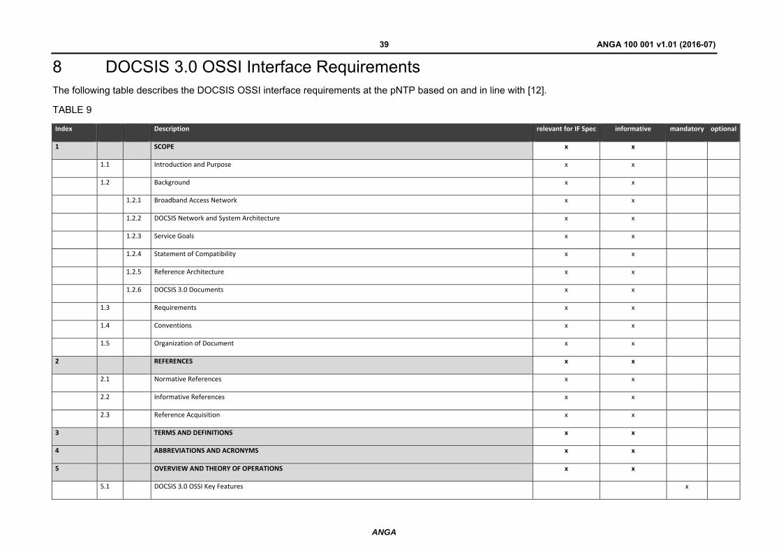
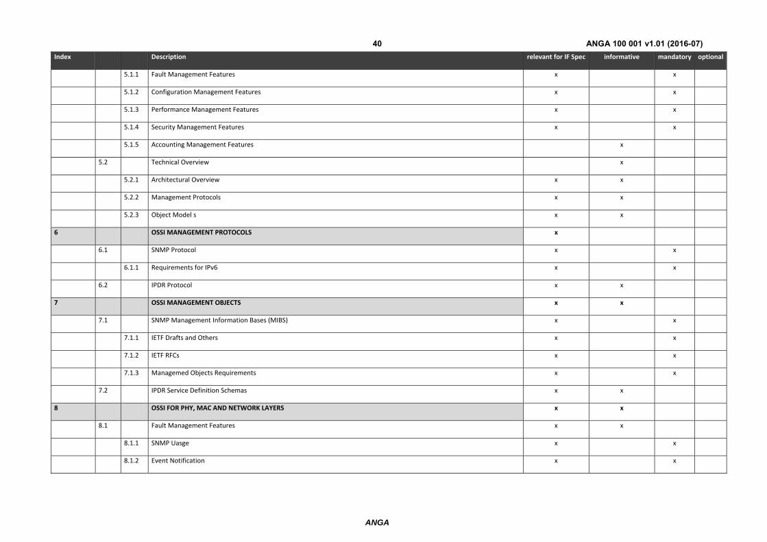
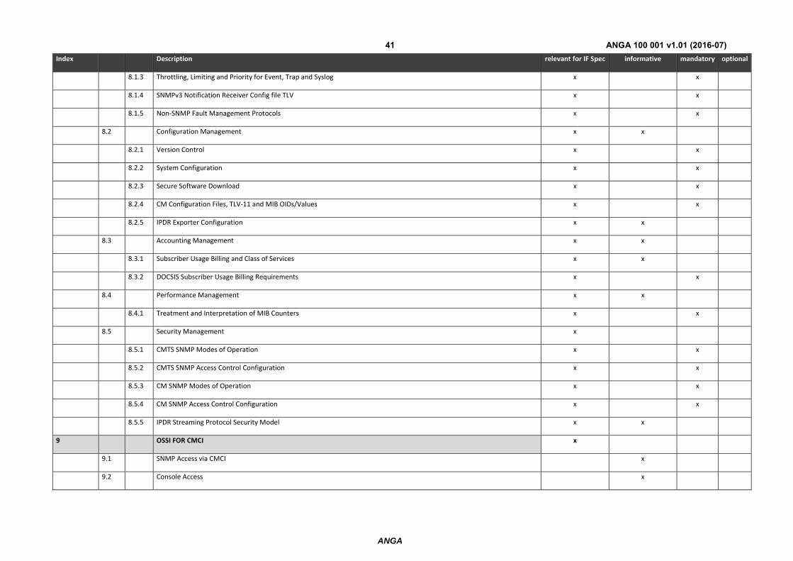
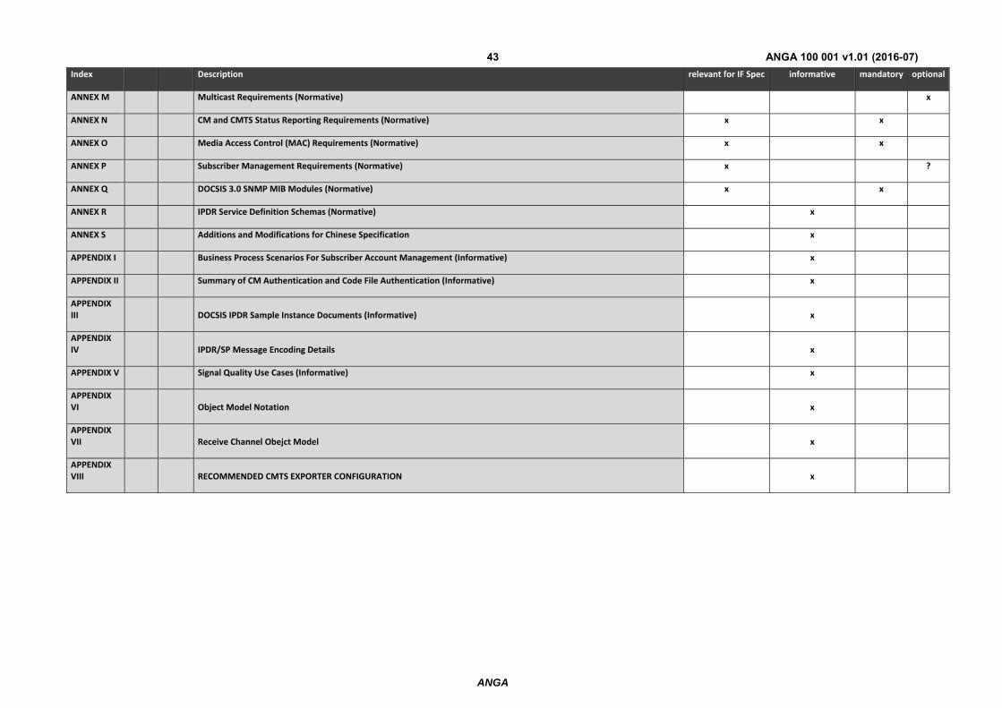
8 DOCSIS 3.0 OSSI Interface Requirements The following table describes the DOCSIS OSSI interface requirements at the pNTP based on and in line with [12].
TABLE 9
Index Description relevant for IF Spec informative mandatory optional
1 SCOPE x x
1.1 Introduction and Purpose x x
1.2 Background x x
1.2.1 Broadband Access Network x x
1.2.2 DOCSIS Network and System Architecture x x
1.2.3 Service Goals x x
1.2.4 Statement of Compatibility x x
1.2.5 Reference Architecture x x
1.2.6 DOCSIS 3.0 Documents x x
1.3 Requirements x x
1.4 Conventions x x
1.5 Organization of Document x x
2 REFERENCES x x
2.1 Normative References x x
2.2 Informative References x x
2.3 Reference Acquisition x x
3 TERMS AND DEFINITIONS x x
4 ABBREVIATIONS AND ACRONYMS x x
5 OVERVIEW AND THEORY OF OPERATIONS x x
5.1 DOCSIS 3.0 OSSI Key Features x
ANGA
ANGA 100 001 v1.01 (2016-07)40
Index Description relevant for IF Spec informative mandatory optional
5.1.1 Fault Management Features x x
5.1.2 Configuration Management Features x x
5.1.3 Performance Management Features x x
5.1.4 Security Management Features x x
5.1.5 Accounting Management Features x
5.2 Technical Overview x
5.2.1 Architectural Overview x x
5.2.2 Management Protocols x x
5.2.3 Object Model s x x
6 OSSI MANAGEMENT PROTOCOLS x
6.1 SNMP Protocol x x
6.1.1 Requirements for IPv6 x x
6.2 IPDR Protocol x x
7 OSSI MANAGEMENT OBJECTS x x
7.1 SNMP Management Information Bases (MIBS) x x
7.1.1 IETF Drafts and Others x x
7.1.2 IETF RFCs x x
7.1.3 Managemed Objects Requirements x x
7.2 IPDR Service Definition Schemas x x
8 OSSI FOR PHY, MAC AND NETWORK LAYERS x x
8.1 Fault Management Features x x
8.1.1 SNMP Uasge x x
8.1.2 Event Notification x x
ANGA
ANGA 100 001 v1.01 (2016-07)41
Index Description relevant for IF Spec informative mandatory optional
8.1.3 Throttling, Limiting and Priority for Event, Trap and Syslog x x
8.1.4 SNMPv3 Notification Receiver Config file TLV x x
8.1.5 Non‐SNMP Fault Management Protocols x x
8.2 Configuration Management x x
8.2.1 Version Control x x
8.2.2 System Configuration x x
8.2.3 Secure Software Download x x
8.2.4 CM Configuration Files, TLV‐11 and MIB OIDs/Values x x
8.2.5 IPDR Exporter Configuration x x
8.3 Accounting Management x x
8.3.1 Subscriber Usage Billing and Class of Services x x
8.3.2 DOCSIS Subscriber Usage Billing Requirements x x
8.4 Performance Management x x
8.4.1 Treatment and Interpretation of MIB Counters x x
8.5 Security Management x
8.5.1 CMTS SNMP Modes of Operation x x
8.5.2 CMTS SNMP Access Control Configuration x x
8.5.3 CM SNMP Modes of Operation x x
8.5.4 CM SNMP Access Control Configuration x x
8.5.5 IPDR Streaming Protocol Security Model x x
9 OSSI FOR CMCI x
9.1 SNMP Access via CMCI x
9.2 Console Access x

ANGA
ANGA 100 001 v1.01 (2016-07)42
Index Description relevant for IF Spec informative mandatory optional
9.3 CM Diagnostic Capabilities x x
9.4 Protocol Filtering x x
10 OSSI FOR CM DEVICE vendor specific
10.1 CM LED Requirements and Operation vendor specific
10.1.1 Power On, Software Application Image Validation and Self Test vendor specific
10.1.2 Scan for Downstream Channel vendor specific
10.1.3 Resolve CM‐SG and Range vendor specific
10.1.4 Operational vendor specific
10.1.5 Data Link and Activity vendor specific
10.2 Additional CM Operational Status Visualization Features vendor specific
10.2.1 Secure Software Download vendor specific
ANNEX A Detailed MIB Requirements (Normative) x x
ANNEX B IPTR for DOCSIS Cable Data Systems Subscriber Usage Billing Records (Normative) x
ANNEX C Auxiliary Schemas for DOCSIS IPDR Service Definitions (Normative) x
ANNEX D Format and Content for Event, SYSLOG, and SNMP Notification (NORMATIVE) x x
ANNEX E Annex E Application of MGMD‐STD‐MIB to DOCSIS 3.0 MGMD Devices (NORMATIVE) x x
ANNEX F Protocol Filtering (Normative) x x
ANNEX G DIAGNOSTIC LOG (Normative) x x
ANNEX H Requirements for DOCS‐IFEXT2‐MIB (Normative) x
ANNEX I Load Balancing Requirements (Normative) x x
ANNEX J Enhanced Signal Quality Monitoring Requirements (Normative) x x
ANNEX K DOCSIS 3.0 Data Type Definitions (Normative) x x
ANNEX L Security Requirements (Normative) x x
ANGA
ANGA 100 001 v1.01 (2016-07)43
Index Description relevant for IF Spec informative mandatory optional
ANNEX M Multicast Requirements (Normative) x
ANNEX N CM and CMTS Status Reporting Requirements (Normative) x x
ANNEX O Media Access Control (MAC) Requirements (Normative) x x
ANNEX P Subscriber Management Requirements (Normative) x ?
ANNEX Q DOCSIS 3.0 SNMP MIB Modules (Normative) x x
ANNEX R IPDR Service Definition Schemas (Normative) x
ANNEX S Additions and Modifications for Chinese Specification x
APPENDIX I Business Process Scenarios For Subscriber Account Management (Informative) x
APPENDIX II Summary of CM Authentication and Code File Authentication (Informative) x
APPENDIX III DOCSIS IPDR Sample Instance Documents (Informative) x
APPENDIX IV IPDR/SP Message Encoding Details x
APPENDIX V Signal Quality Use Cases (Informative) x
APPENDIX VI Object Model Notation x
APPENDIX VII Receive Channel Obejct Model x
APPENDIX VIII RECOMMENDED CMTS EXPORTER CONFIGURATION x
ANGA
ANGA 100 001 v1.01 (2016-07)44
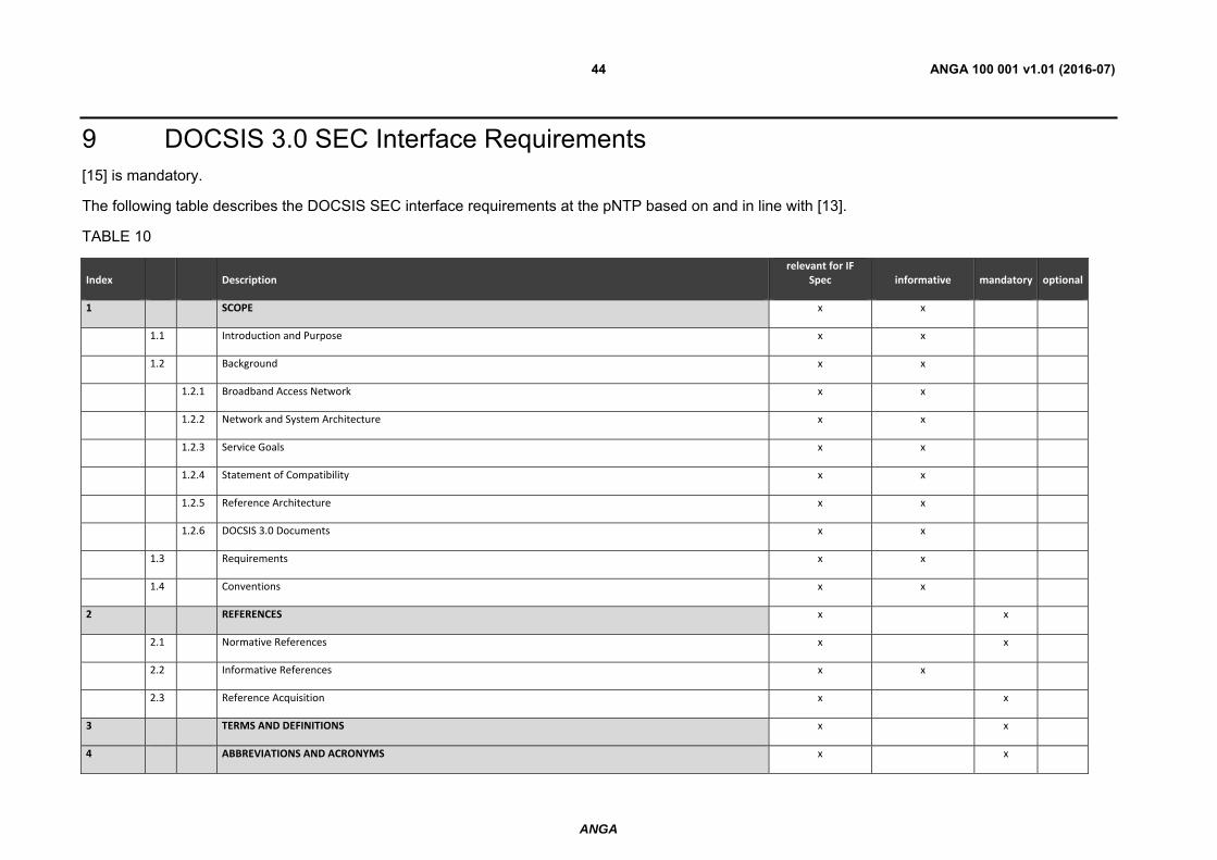
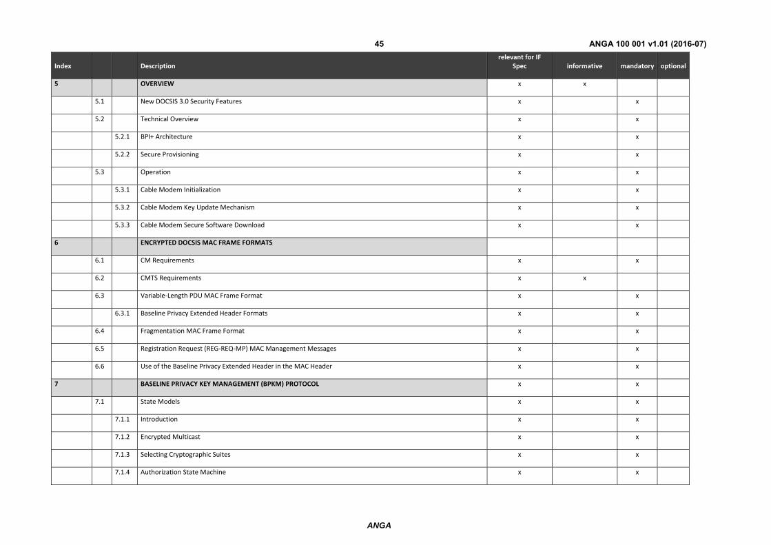
9 DOCSIS 3.0 SEC Interface Requirements [15] is mandatory.
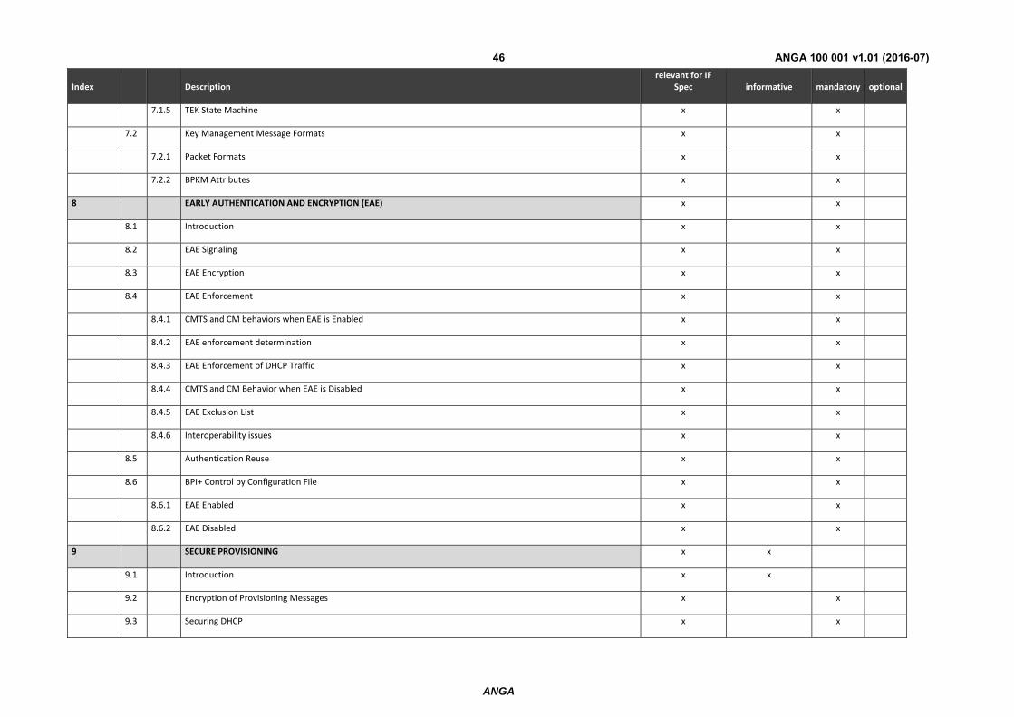
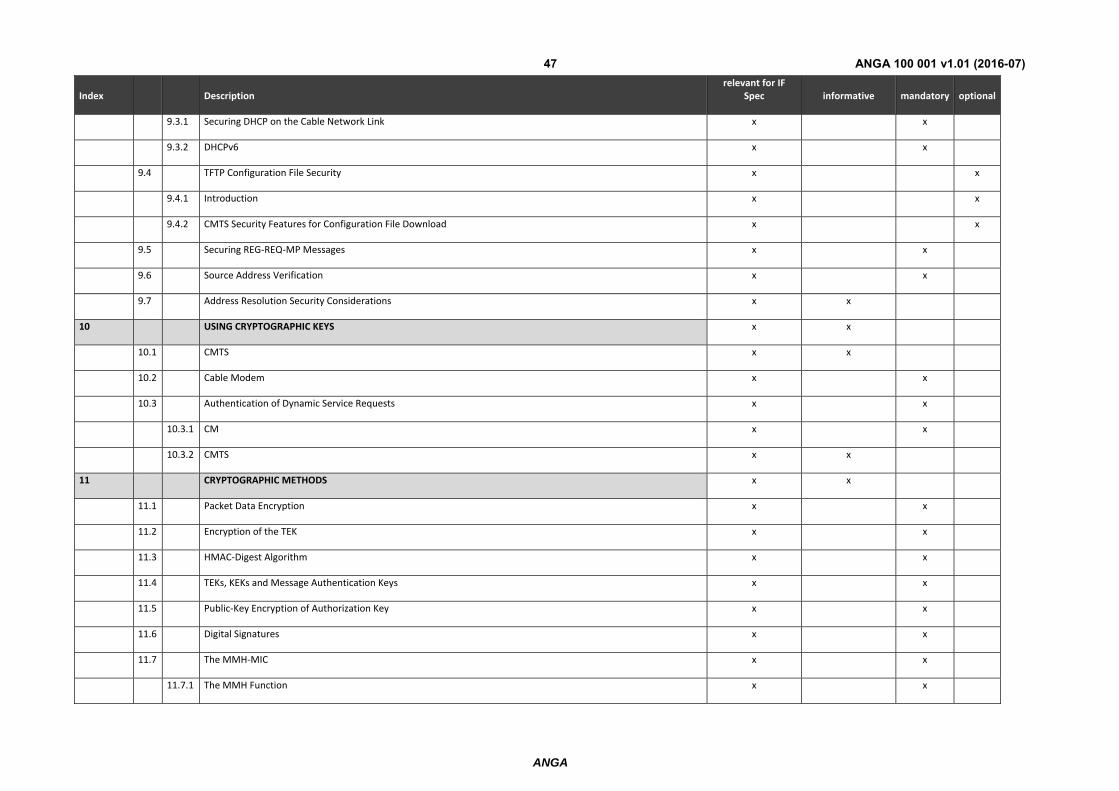
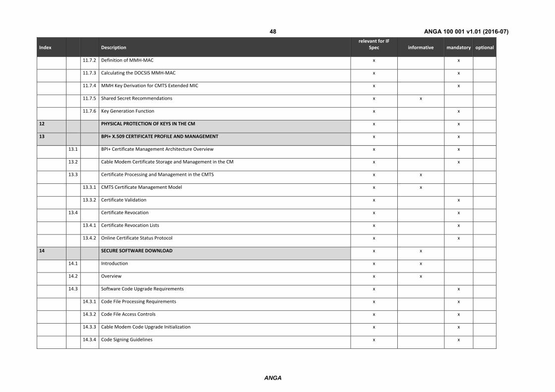
The following table describes the DOCSIS SEC interface requirements at the pNTP based on and in line with [13].
TABLE 10
Index Description relevant for IF
Spec informative mandatory optional
1 SCOPE x x
1.1 Introduction and Purpose x x
1.2 Background x x
1.2.1 Broadband Access Network x x
1.2.2 Network and System Architecture x x
1.2.3 Service Goals x x
1.2.4 Statement of Compatibility x x
1.2.5 Reference Architecture x x
1.2.6 DOCSIS 3.0 Documents x x
1.3 Requirements x x
1.4 Conventions x x
2 REFERENCES x x
2.1 Normative References x x
2.2 Informative References x x
2.3 Reference Acquisition x x
3 TERMS AND DEFINITIONS x x
4 ABBREVIATIONS AND ACRONYMS x x
ANGA
ANGA 100 001 v1.01 (2016-07)45
Index Description relevant for IF
Spec informative mandatory optional
5 OVERVIEW x x
5.1 New DOCSIS 3.0 Security Features x x
5.2 Technical Overview x x
5.2.1 BPI+ Architecture x x
5.2.2 Secure Provisioning x x
5.3 Operation x x
5.3.1 Cable Modem Initialization x x
5.3.2 Cable Modem Key Update Mechanism x x
5.3.3 Cable Modem Secure Software Download x x
6 ENCRYPTED DOCSIS MAC FRAME FORMATS
6.1 CM Requirements x x
6.2 CMTS Requirements x x
6.3 Variable‐Length PDU MAC Frame Format x x
6.3.1 Baseline Privacy Extended Header Formats x x
6.4 Fragmentation MAC Frame Format x x
6.5 Registration Request (REG‐REQ‐MP) MAC Management Messages x x
6.6 Use of the Baseline Privacy Extended Header in the MAC Header x x
7 BASELINE PRIVACY KEY MANAGEMENT (BPKM) PROTOCOL x x
7.1 State Models x x
7.1.1 Introduction x x
7.1.2 Encrypted Multicast x x
7.1.3 Selecting Cryptographic Suites x x
7.1.4 Authorization State Machine x x
ANGA
ANGA 100 001 v1.01 (2016-07)46
Index Description relevant for IF
Spec informative mandatory optional
7.1.5 TEK State Machine x x
7.2 Key Management Message Formats x x
7.2.1 Packet Formats x x
7.2.2 BPKM Attributes x x
8 EARLY AUTHENTICATION AND ENCRYPTION (EAE) x x
8.1 Introduction x x
8.2 EAE Signaling x x
8.3 EAE Encryption x x
8.4 EAE Enforcement x x
8.4.1 CMTS and CM behaviors when EAE is Enabled x x
8.4.2 EAE enforcement determination x x
8.4.3 EAE Enforcement of DHCP Traffic x x
8.4.4 CMTS and CM Behavior when EAE is Disabled x x
8.4.5 EAE Exclusion List x x
8.4.6 Interoperability issues x x
8.5 Authentication Reuse x x
8.6 BPI+ Control by Configuration File x x
8.6.1 EAE Enabled x x
8.6.2 EAE Disabled x x
9 SECURE PROVISIONING x x
9.1 Introduction x x
9.2 Encryption of Provisioning Messages x x
9.3 Securing DHCP x x
ANGA
ANGA 100 001 v1.01 (2016-07)47
Index Description relevant for IF
Spec informative mandatory optional
9.3.1 Securing DHCP on the Cable Network Link x x
9.3.2 DHCPv6 x x
9.4 TFTP Configuration File Security x x
9.4.1 Introduction x x
9.4.2 CMTS Security Features for Configuration File Download x x
9.5 Securing REG‐REQ‐MP Messages x x
9.6 Source Address Verification x x
9.7 Address Resolution Security Considerations x x
10 USING CRYPTOGRAPHIC KEYS x x
10.1 CMTS x x
10.2 Cable Modem x x
10.3 Authentication of Dynamic Service Requests x x
10.3.1 CM x x
10.3.2 CMTS x x
11 CRYPTOGRAPHIC METHODS x x
11.1 Packet Data Encryption x x
11.2 Encryption of the TEK x x
11.3 HMAC‐Digest Algorithm x x
11.4 TEKs, KEKs and Message Authentication Keys x x
11.5 Public‐Key Encryption of Authorization Key x x
11.6 Digital Signatures x x
11.7 The MMH‐MIC x x
11.7.1 The MMH Function x x
ANGA
ANGA 100 001 v1.01 (2016-07)48
Index Description relevant for IF
Spec informative mandatory optional
11.7.2 Definition of MMH‐MAC x x
11.7.3 Calculating the DOCSIS MMH‐MAC x x
11.7.4 MMH Key Derivation for CMTS Extended MIC x x
11.7.5 Shared Secret Recommendations x x
11.7.6 Key Generation Function x x
12 PHYSICAL PROTECTION OF KEYS IN THE CM x x
13 BPI+ X.509 CERTIFICATE PROFILE AND MANAGEMENT x x
13.1 BPI+ Certificate Management Architecture Overview x x
13.2 Cable Modem Certificate Storage and Management in the CM x x
13.3 Certificate Processing and Management in the CMTS x x
13.3.1 CMTS Certificate Management Model x x
13.3.2 Certificate Validation x x
13.4 Certificate Revocation x x
13.4.1 Certificate Revocation Lists x x
13.4.2 Online Certificate Status Protocol x x
14 SECURE SOFTWARE DOWNLOAD x x
14.1 Introduction x x
14.2 Overview x x
14.3 Software Code Upgrade Requirements x x
14.3.1 Code File Processing Requirements x x
14.3.2 Code File Access Controls x x
14.3.3 Cable Modem Code Upgrade Initialization x x
14.3.4 Code Signing Guidelines x x
ANGA
ANGA 100 001 v1.01 (2016-07)49
Index Description relevant for IF
Spec informative mandatory optional
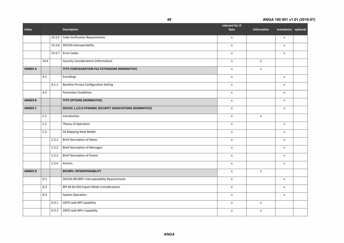
14.3.5 Code Verification Requirements x x
14.3.6 DOCSIS Interoperability x x
14.3.7 Error Codes x x
14.4 Security Considerations (Informative) x x
ANNEX A TFTP CONFIGURATION FILE EXTENSIONS (NORMATIVE) x x
A.1 Encodings x x
A.1.1 Baseline Privacy Configuration Setting x x
A.2 Parameter Guidelines x x
ANNEX B TFTP OPTIONS (NORMATIVE) x x
ANNEX C DOCSIS 1.1/2.0 DYNAMIC SECURITY ASSOCIATIONS (NORMATIVE) x x
C.1 Introduction x x
C.2 Theory of Operation x x
C.3 SA Mapping State Model x x
C.3.1 Brief Description of States x x
C.3.2 Brief Description of Messages x x
C.3.3 Brief Description of Events x x
C.3.4 Actions x x
ANNEX D BPI/BPI+ INTEROPERABILITY x x
D.1 DOCSIS BPI/BPI+ Interoperability Requirements x x
D.2 BPI 40‐bit DES Export Mode Considerations x x
D.3 System Operation x x
D.3.1 CMTS with BPI Capability x x
D.3.2 CMTS with BPI+ Capability x x

ANGA
ANGA 100 001 v1.01 (2016-07)50
Index Description relevant for IF
Spec informative mandatory optional
ANNEX E ADDITIONS AND MODIFICATIONS FOR CHINESE SPECIFICATION
E.1 Security requirement differences for C‐DOCSIS
APPENDIX I EXAMPLE MESSAGES, CERTIFICATES, PDUS AND CODE FILE (INFORMATIVE) x x
I.1 Notation x x
I.2 Authentication Info x x
I.2.1 CA Certificate details x x
I.3 Authorization Request x x
I.3.1 CM Certificate details x x
I.4 Authorization Reply x x
I.4.1 RSA encryption details x x
I.4.2 RSA decryption details x x
I.4.3 Hashing details x x
I.5 Key Request x x
I.5.1 HMAC digest details x x
I.6 Key Reply x x
I.6.1 TEK encryption details x x
I.6.2 HMAC details x x
I.7 Packet PDU encryption (DES) x x
I.7.1 CBC only x x
I.7.2 CBC with residual block processing x x
I.7.3 Runt frame x x
I.7.4 40‐bit key x x
ANGA
ANGA 100 001 v1.01 (2016-07)51
Index Description relevant for IF
Spec informative mandatory optional
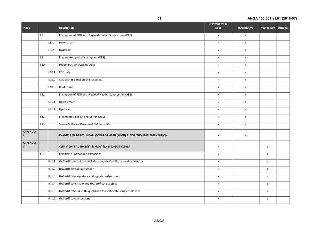
I.8 Encryption of PDU with Payload Header Suppression (DES) x x
I.8.1 Downstream x x
I.8.2 Upstream x x
I.9 Fragmented packet encryption (DES) x x
I.10 Packet PDU encryption (AES) x x
I.10.1 CBC only x x
I.10.2 CBC with residual block processing x x
I.10.3 Runt frame x x
I.11 Encryption of PDU with Payload Header Suppression (AES) x x
I.11.1 Downstream x x
I.11.2 Upstream x x
I.12 Fragmented packet encryption (AES) x x
I.13 Secure Software Download CM Code File x x
APPENDIX II EXAMPLE OF MULTILINEAR MODULAR HASH (MMH) ALGORITHM IMPLEMENTATION x x
APPENDIX III CERTIFICATE AUTHORITY & PROVISIONING GUIDELINES x x
III.1 Certificate Format and Extensions x x
III.1.1 tbsCertificate.validity.notBefore and tbsCertificate.validity.notAfter x x
III.1.2 tbsCertificate.serialNumber x x
III.1.3 tbsCertificate.signature and signatureAlgorithm x x
III.1.4 tbsCertificate.issuer and tbsCertificate.subject x x
III.1.5 tbsCertificate.issuerUniqueID and tbsCertificate.subjectUniqueID x x
III.1.6 tbsCertificate.extensions x x
ANGA
ANGA 100 001 v1.01 (2016-07)52
Index Description relevant for IF
Spec informative mandatory optional
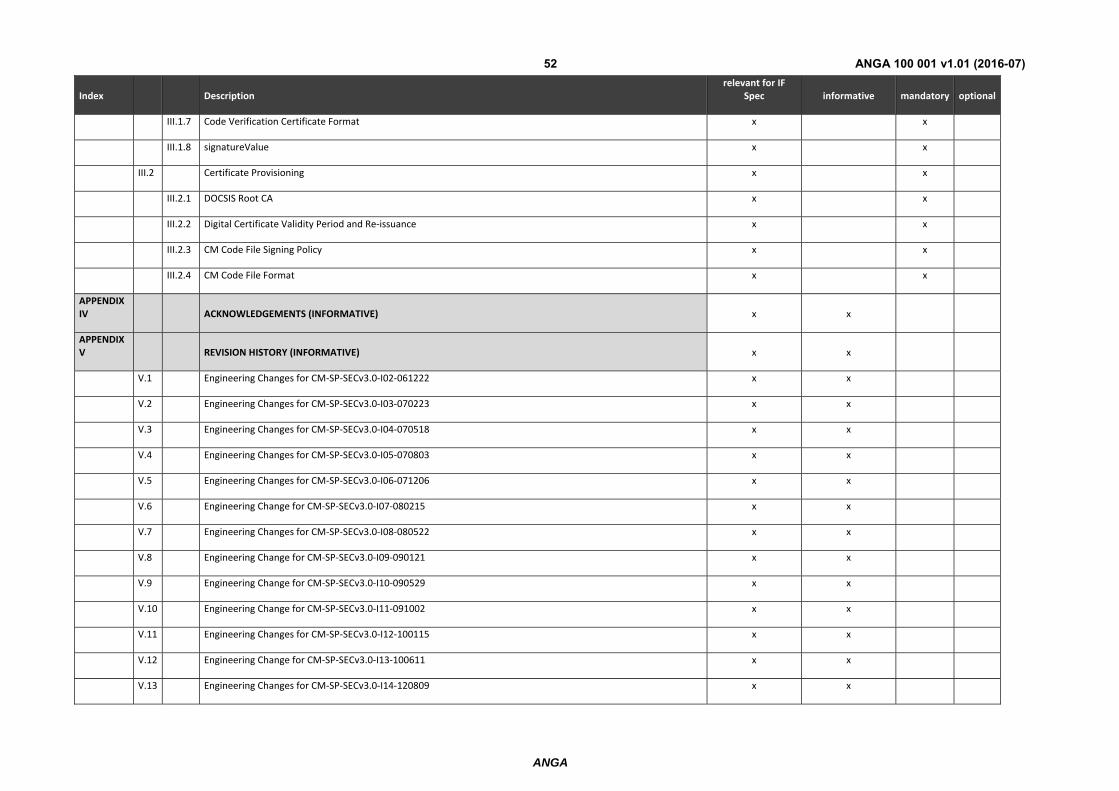
III.1.7 Code Verification Certificate Format x x
III.1.8 signatureValue x x
III.2 Certificate Provisioning x x
III.2.1 DOCSIS Root CA x x
III.2.2 Digital Certificate Validity Period and Re‐issuance x x
III.2.3 CM Code File Signing Policy x x
III.2.4 CM Code File Format x x
APPENDIX IV ACKNOWLEDGEMENTS (INFORMATIVE) x x
APPENDIX V REVISION HISTORY (INFORMATIVE) x x
V.1 Engineering Changes for CM‐SP‐SECv3.0‐I02‐061222 x x
V.2 Engineering Changes for CM‐SP‐SECv3.0‐I03‐070223 x x
V.3 Engineering Changes for CM‐SP‐SECv3.0‐I04‐070518 x x
V.4 Engineering Changes for CM‐SP‐SECv3.0‐I05‐070803 x x
V.5 Engineering Changes for CM‐SP‐SECv3.0‐I06‐071206 x x
V.6 Engineering Change for CM‐SP‐SECv3.0‐I07‐080215 x x
V.7 Engineering Changes for CM‐SP‐SECv3.0‐I08‐080522 x x
V.8 Engineering Change for CM‐SP‐SECv3.0‐I09‐090121 x x
V.9 Engineering Change for CM‐SP‐SECv3.0‐I10‐090529 x x
V.10 Engineering Change for CM‐SP‐SECv3.0‐I11‐091002 x x
V.11 Engineering Changes for CM‐SP‐SECv3.0‐I12‐100115 x x
V.12 Engineering Change for CM‐SP‐SECv3.0‐I13‐100611 x x
V.13 Engineering Changes for CM‐SP‐SECv3.0‐I14‐120809 x x
ANGA
ANGA 100 001 v1.01 (2016-07)53
Index Description relevant for IF
Spec informative mandatory optional
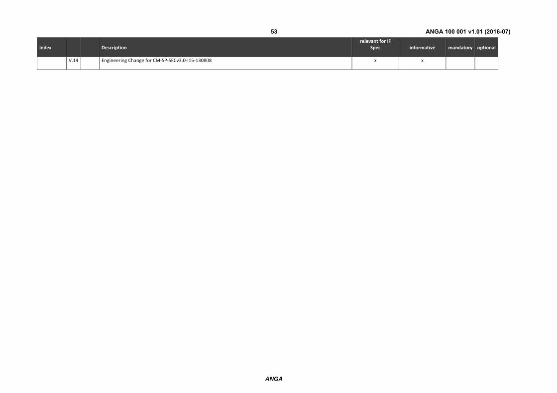
V.14 Engineering Change for CM‐SP‐SECv3.0‐I15‐130808 x x
ANGA
ANGA 100 001 v1.01 (2016-07)54
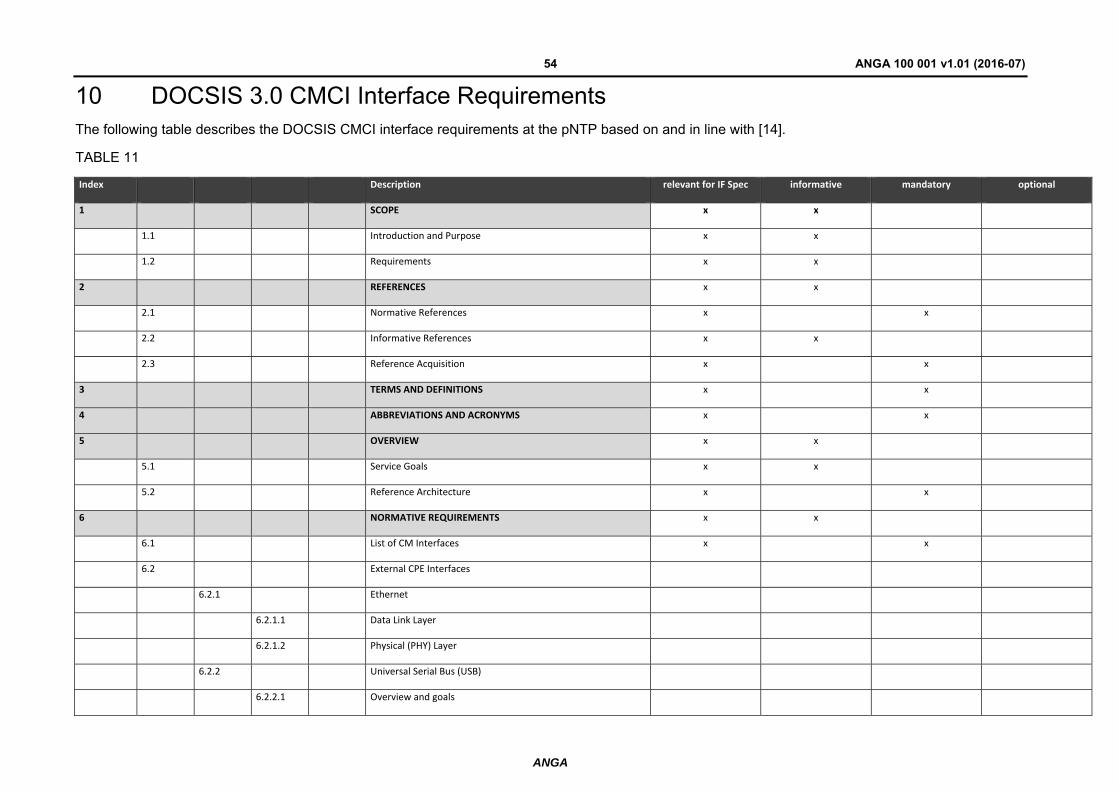
10 DOCSIS 3.0 CMCI Interface Requirements The following table describes the DOCSIS CMCI interface requirements at the pNTP based on and in line with [14].
TABLE 11
Index Description relevant for IF Spec informative mandatory optional
1 SCOPE x x
1.1 Introduction and Purpose x x
1.2 Requirements x x
2 REFERENCES x x
2.1 Normative References x x
2.2 Informative References x x
2.3 Reference Acquisition x x
3 TERMS AND DEFINITIONS x x
4 ABBREVIATIONS AND ACRONYMS x x
5 OVERVIEW x x
5.1 Service Goals x x
5.2 Reference Architecture x x
6 NORMATIVE REQUIREMENTS x x
6.1 List of CM Interfaces x x
6.2 External CPE Interfaces
6.2.1 Ethernet
6.2.1.1 Data Link Layer
6.2.1.2 Physical (PHY) Layer
6.2.2 Universal Serial Bus (USB)
6.2.2.1 Overview and goals
ANGA
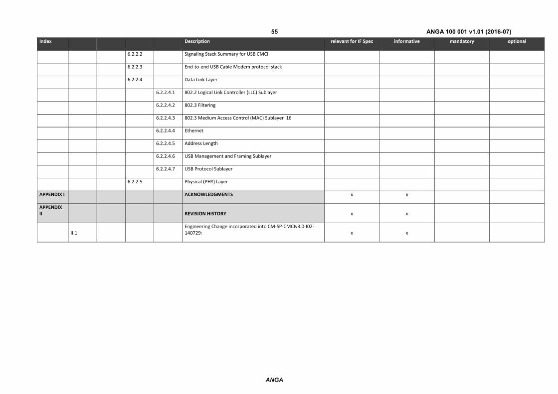
ANGA 100 001 v1.01 (2016-07)55
Index Description relevant for IF Spec informative mandatory optional
6.2.2.2 Signaling Stack Summary for USB CMCI
6.2.2.3 End‐to‐end USB Cable Modem protocol stack
6.2.2.4 Data Link Layer
6.2.2.4.1 802.2 Logical Link Controller (LLC) Sublayer
6.2.2.4.2 802.3 Filtering
6.2.2.4.3 802.3 Medium Access Control (MAC) Sublayer 16
6.2.2.4.4 Ethernet
6.2.2.4.5 Address Length
6.2.2.4.6 USB Management and Framing Sublayer
6.2.2.4.7 USB Protocol Sublayer
6.2.2.5 Physical (PHY) Layer
APPENDIX I ACKNOWLEDGMENTS x x
APPENDIX II REVISION HISTORY x x
II.1 Engineering Change incorporated into CM‐SP‐CMCIv3.0‐I02‐140729: x x
ANGA
ANGA 100 001 v1.01 (2016-07)56
Annex 1 (informative): Implementation Advice
1.1 Coaxial cable assemblies
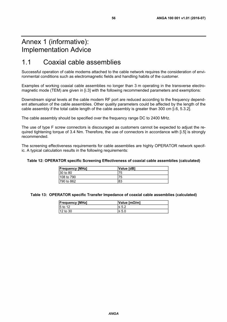
Successful operation of cable modems attached to the cable network requires the consideration of envi-ronmental conditions such as electromagnetic fields and handling habits of the customer. Examples of working coaxial cable assemblies no longer than 3 m operating in the transverse electro-magnetic mode (TEM) are given in [i.3] with the following recommended parameters and exemptions: Downstream signal levels at the cable modem RF port are reduced according to the frequency depend-ent attenuation of the cable assemblies. Other quality parameters could be affected by the length of the cable assembly if the total cable length of the cable assembly is greater than 300 cm [i.6, 5.3.2]. The cable assembly should be specified over the frequency range DC to 2400 MHz. The use of type F screw connectors is discouraged as customers cannot be expected to adjust the re-quired tightening torque of 3.4 Nm. Therefore, the use of connectors in accordance with [i.5] is strongly recommended. The screening effectiveness requirements for cable assemblies are highly OPERATOR network specif-ic. A typical calculation results in the following requirements:
Table 12: OPERATOR specific Screening Effectiveness of coaxial cable assemblies (calculated)
Frequency [MHz] Value [dB]30 to 80 75 108 to 790 75 790 to 862 83
Table 13: OPERATOR specific Transfer Impedance of coaxial cable assemblies (calculated)
Frequency [MHz] Value [mΩ/m]5 to 12 ≤ 5.2 12 to 30 ≤ 5.0
ANGA
ANGA 100 001 v1.01 (2016-07)57
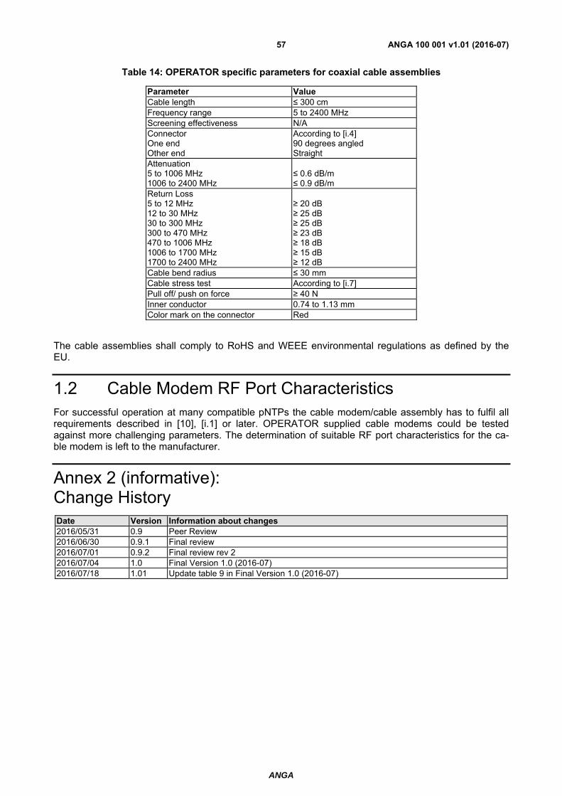
Table 14: OPERATOR specific parameters for coaxial cable assemblies
Parameter ValueCable length ≤ 300 cm Frequency range 5 to 2400 MHz Screening effectiveness N/A Connector One end Other end
According to [i.4] 90 degrees angled Straight
Attenuation 5 to 1006 MHz 1006 to 2400 MHz
≤ 0.6 dB/m ≤ 0.9 dB/m
Return Loss 5 to 12 MHz 12 to 30 MHz 30 to 300 MHz 300 to 470 MHz 470 to 1006 MHz 1006 to 1700 MHz 1700 to 2400 MHz
≥ 20 dB ≥ 25 dB ≥ 25 dB ≥ 23 dB ≥ 18 dB ≥ 15 dB ≥ 12 dB
Cable bend radius ≤ 30 mm Cable stress test According to [i.7] Pull off/ push on force ≥ 40 N Inner conductor 0.74 to 1.13 mm Color mark on the connector Red
The cable assemblies shall comply to RoHS and WEEE environmental regulations as defined by the EU.
1.2 Cable Modem RF Port Characteristics
For successful operation at many compatible pNTPs the cable modem/cable assembly has to fulfil all requirements described in [10], [i.1] or later. OPERATOR supplied cable modems could be tested against more challenging parameters. The determination of suitable RF port characteristics for the ca-ble modem is left to the manufacturer.
Annex 2 (informative): Change History Date Version Information about changes2016/05/31 0.9 Peer Review 2016/06/30 0.9.1 Final review 2016/07/01 0.9.2 Final review rev 2 2016/07/04 1.0 Final Version 1.0 (2016-07) 2016/07/18 1.01 Update table 9 in Final Version 1.0 (2016-07)

ANGA
ANGA 100 001 v1.01 (2016-07)58
History
Document history
<Version> <Date> <Milestone>
1 2016/07/04 Initial version V1.0 (2016-7)
1.01 2016/07/18 Initial version V1.01 (2016-7) Update table 9 section 8