specification sheet masterseries 856st - watts watermedia3.wattswater.com/es-f-856st.pdf ·...
TRANSCRIPT
ES-F-856ST
MasterSeries® 856STDouble Check Detector Backflow Prevention AssembliesSize: 21⁄2" - 10" (65mm - 250mm)
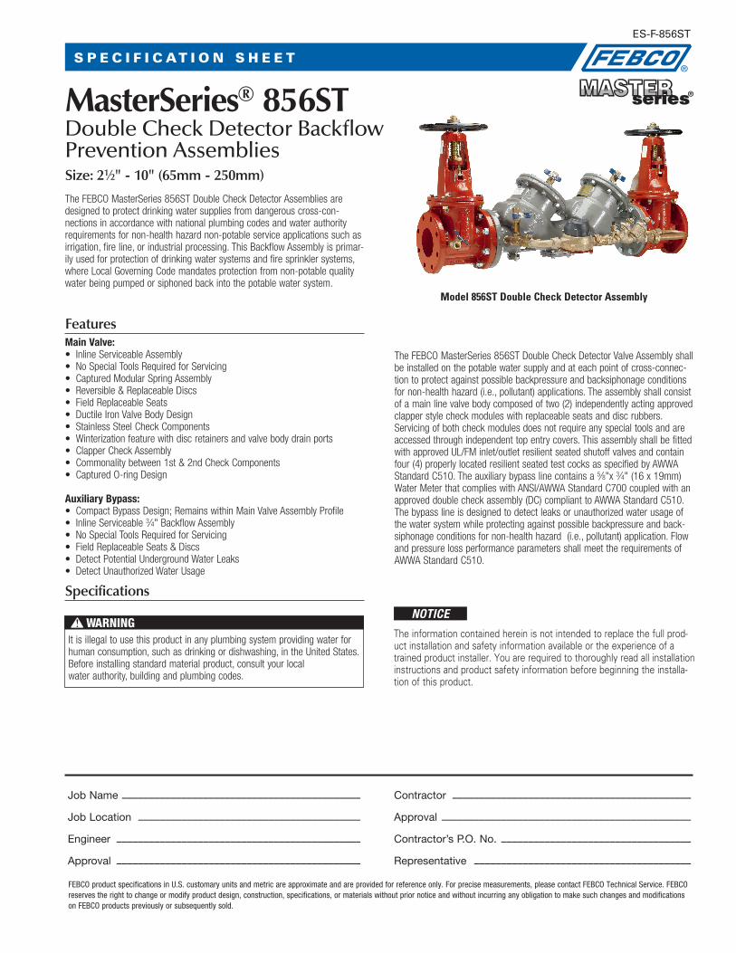
Model 856ST Double Check Detector Assembly
The FEBCO MasterSeries 856ST Double Check Detector Assemblies are designed to protect drinking water supplies from dangerous cross-con-nections in accordance with national plumbing codes and water authority requirements for non-health hazard non-potable service applications such as irrigation, fire line, or industrial processing. This Backflow Assembly is primar-ily used for protection of drinking water systems and fire sprinkler systems, where Local Governing Code mandates protection from non-potable quality water being pumped or siphoned back into the potable water system.
FeaturesMain Valve:• InlineServiceableAssembly• NoSpecialToolsRequiredforServicing• CapturedModularSpringAssembly• Reversible&ReplaceableDiscs• FieldReplaceableSeats• DuctileIronValveBodyDesign• StainlessSteelCheckComponents• Winterizationfeaturewithdiscretainersandvalvebodydrainports• ClapperCheckAssembly• Commonalitybetween1st&2ndCheckComponents• CapturedO-ringDesign
Auxiliary Bypass:• CompactBypassDesign;RemainswithinMainValveAssemblyProfile• InlineServiceable3⁄4" Backflow Assembly• NoSpecialToolsRequiredforServicing• FieldReplaceableSeats&Discs• DetectPotentialUndergroundWaterLeaks• DetectUnauthorizedWaterUsage
Specifications
TheFEBCOMasterSeries856STDoubleCheckDetectorValveAssemblyshallbe installed on the potable water supply and at each point of cross-connec-tion to protect against possible backpressure and backsiphonage conditions for non-health hazard (i.e., pollutant) applications. The assembly shall consist ofamainlinevalvebodycomposedoftwo(2)independentlyactingapprovedclapper style check modules with replaceable seats and disc rubbers. Servicing of both check modules does not require any special tools and are accessed through independent top entry covers. This assembly shall be fitted withapprovedUL/FMinlet/outletresilientseatedshutoffvalvesandcontainfour(4)properlylocatedresilientseatedtestcocksasspecifiedbyAWWAStandardC510.Theauxiliarybypasslinecontainsa5⁄8"x3⁄4"(16x19mm)WaterMeterthatcomplieswithANSI/AWWAStandardC700coupledwithanapproveddoublecheckassembly(DC)complianttoAWWAStandardC510.The bypass line is designed to detect leaks or unauthorized water usage of the water system while protecting against possible backpressure and back-siphonage conditions for non-health hazard (i.e., pollutant) application. Flow and pressure loss performance parameters shall meet the requirements of AWWAStandardC510.
NOTICEThe information contained herein is not intended to replace the full prod-uct installation and safety information available or the experience of a trained product installer. You are required to thoroughly read all installation instructions and product safety information before beginning the installa-tion of this product.
S P E C I F I C AT I O N S H E E T
Itisillegaltousethisproductinanyplumbingsystemprovidingwaterforhumanconsumption,suchasdrinkingordishwashing,intheUnitedStates.Before installing standard material product, consult your local water authority, building and plumbing codes.
WARNING!
FEBCO product specifications in U.S. customary units and metric are approximate and are provided for reference only. For precise measurements, please contact FEBCO Technical Service. FEBCO reserves the right to change or modify product design, construction, specifications, or materials without prior notice and without incurring any obligation to make such changes and modifications on FEBCO products previously or subsequently sold.
Job Name –––––––––––––––––––––––––––––––––––––––––––– Contractor ––––––––––––––––––––––––––––––––––––––––––––
Job Location ––––––––––––––––––––––––––––––––––––––––– Approval ––––––––––––––––––––––––––––––––––––––––––––––
Engineer ––––––––––––––––––––––––––––––––––––––––––––– Contractor’s P.O. No. –––––––––––––––––––––––––––––––––––
Approval ––––––––––––––––––––––––––––––––––––––––––––– Representative ––––––––––––––––––––––––––––––––––––––––
Approvals• ApprovedbytheFoundationforCross-ConnectionControlandHydraulicResearchatTheUniversityofSouthernCalifornia(FCCCHR-USC)
• ASSE1048Listed
• **ULClassified(US&Canada)
• **FMApproved
• IAPMO
• AWWAStandardC510Compliant
• EndConnections:ComplianttoASMEB16.1Class125&AWWAClassDFlange
**AssemblyconfiguredwithUL/FMApprovedOS&YRWGateValves.LessgatevalveassembliesarenotUL/FMapprovedconfigurations.
Pressure - TemperatureMax.WorkingPressure: 175psi(12.1bar)
Min.WorkingPressure: 10psi(0.7bar)
HydrostaticTestPressure: 350psi(24.1bar)
HydrostaticSafetyPressure: 700psi(48.3bar)
TemperatureRange: 33°F-140°F(0.5°C-60°C)Continuous
Options - SuffixOSY: UL/FMApprovedOS&YGateValves
(ANSI/AWWAC515Compliant)
CFM: TotalizingCubicfeet/min5/8"x3/4"WaterMeter (ANSI/AWWAC700Compliant)
GPM:TotalizingGallons/min5/8"x3/4"WaterMeter (ANSI/AWWAC700Compliant)
LG: LessShutoffvalves;ThisisNOTanAPPROVEDASSEMBLY
Example Ordering Descriptions:
4"856ST-OSY-GPM-ValveAssemblyfittedwithOS&YShutoffValves&GallonFeetperMinuteWaterMeter
4"856ST-OSY-CFM-ValveAssemblyfittedwithOS&YShutoffValves,CubicfeetperMinuteWaterMeter
Assembly Flow Orientation:• Horizontal&VerticalUp(21⁄2"–10")-ApprovedbyFCCCHR-USC,ASSE,
cULus,FM,IAPMO
MaterialsBelowisageneralmateriallistoftheModel856ST.Allassemblies’size21⁄2" through10"issimilarinmaterialsandconstruction.PleasecontactyourlocalFEBCORepresentativeifyourequirefurtherinformation.
MainValveBody: DuctileironGrade65-45-12
Coating: Fusionepoxycoatedinternalandexternal AWWAC550
ShutoffValves: OS&YresilientwedgegatevalvesAWWAC515(UL/FM)
CheckSeats: StainlessSteel
DiscHolder: StainlessSteel
Elastomer Disc Silicone
Spring: StainlessSteel
Clamp: AWWAC606(10"Only)
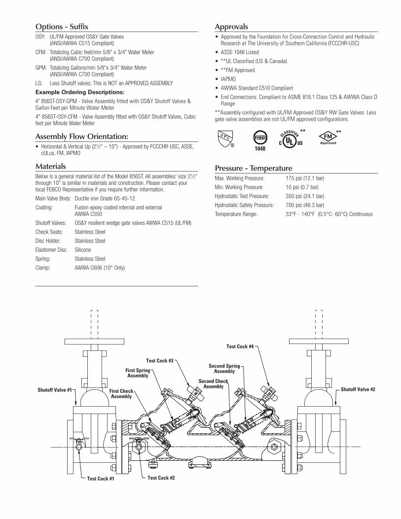
Test Cock #1 Test Cock #2
First SpringAssembly
First CheckAssembly
Second SpringAssembly
Second CheckAssemblyShutoff Vavle #1 Shutoff Valve #2
Test Cock #3
Test Cock #4
Shutoff Valve #1 Shutoff Valve #2
Test Cock #3
Test Cock #4
Test Cock #2Test Cock #1
First Check Assembly
First Spring Assembly
Second Spring Assembly
Second Check Assembly
1048
****
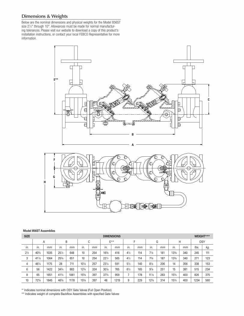
Dimensions & WeightsBelow are the nominal dimensions and physical weights for the Model 856ST size21⁄2"through10".Allowancesmustbemadefornormalmanufactur-ingtolerances.Pleasevisitourwebsitetodownloadacopyofthisproduct’sinstallationinstructions,orcontactyourlocalFEBCORepresentativeformoreinformation.
Model 856ST Assemblies
SIZE DIMENSIONS WEIGHT***
A B C E** F G H OSY
in. in. mm in. mm in. mm in. mm in. mm in. mm in. mm lbs. kg.
21⁄2 403⁄4 1035 251⁄2 648 10 254 163⁄8 416 41⁄2 114 71⁄8 181 133⁄8 340 245 111
3 417⁄8 1064 255⁄8 651 10 254 221⁄7 565 41⁄2 114 73⁄8 187 133⁄8 340 271 123
4 461⁄4 1175 28 711 101⁄8 257 231⁄4 591 51⁄2 140 81⁄8 206 14 356 338 153
6 56 1422 343⁄4 883 123⁄4 324 301⁄8 765 61⁄2 165 97⁄8 251 15 381 515 234
8 65 1651 413⁄4 1061 155⁄8 397 373⁄4 959 7 178 111⁄8 283 153⁄4 400 826 375
10 725⁄8 1845 463⁄8 1178 155⁄8 397 48 1219 9 229 123⁄8 314 153⁄4 400 1234 560
** Indicates nominal dimensions with OSY Gate Valves (Full Open Position)*** Indicates weight of complete Backflow Assemblies with specified Gate Valves
A
B
C
D
G
F
E
E**
A
H
G
F
B
C
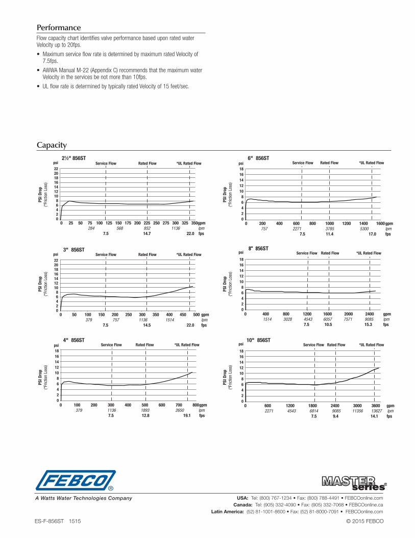
PerformanceFlow capacity chart identifies valve performance based upon rated water Velocityupto20fps.
• MaximumserviceflowrateisdeterminedbymaximumratedVelocityof7.5fps.
• AWWAManualM-22(AppendixC)recommendsthatthemaximumwaterVelocityintheservicesbenotmorethan10fps.
• ULflowrateisdeterminedbytypicallyratedVelocityof15feet/sec.
21⁄2" 856ST
3" 856ST
4" 856ST
6" 856ST
8" 856ST
10" 856ST
psi
22 20 18 16 14 12 10 8 6 4 2 0
psi
22 20 18 16 14 12 10 8 6 4 2 0
psi 18 16 14 12 10 8 6 4 2 0
psi 18 16 14 12 10 8 6 4 2 0
psi
18 16 14 12 10 8 6 4 2 0
psi
18 16 14 12 10 8 6 4 2 0
0 25 50 75 100 125 150 175 200 225 250 275 300 325 350 gpm 284 568 852 1136 lpm 7.5 14.7 22.0 fps
0 50 100 150 200 250 300 350 400 450 500 gpm 379 757 1136 1514 lpm 7.5 14.5 22.0 fps
0 100 200 300 400 500 600 700 800 gpm 379 1136 1893 2650 lpm 7.5 12.8 19.1 fps
0 200 400 600 800 1000 1200 1400 1600 gpm 757 2271 3785 5300 lpm 7.5 11.4 17.0 fps
0 400 800 1200 1600 2000 2400 gpm 1514 3028 4543 6057 7571 9085 lpm 7.5 10.5 15.3 fps
0 600 1200 1800 2400 3000 3600 gpm 2271 4543 6814 9085 11356 13627 lpm 7.5 9.4 14.1 fps
Service Flow
Service Flow
Service Flow
Service Flow
Service Flow
Service Flow
Rated Flow
Rated Flow
Rated Flow
Rated Flow
Rated Flow
Rated Flow
*UL Rated Flow
*UL Rated Flow
*UL Rated Flow
*UL Rated Flow
*UL Rated Flow
*UL Rated Flow
Capacity
PSI D
rop
(*Fr
ictio
n Lo
ss)
PSI D
rop
(*Fr
ictio
n Lo
ss)
PSI D
rop
(*Fr
ictio
n Lo
ss)
PSI D
rop
(*Fr
ictio
n Lo
ss)
PSI D
rop
(*Fr
ictio
n Lo
ss)
PSI D
rop
(*Fr
ictio
n Lo
ss)
ES-F-856ST 1515 © 2015 FEBCO
USA: Tel: (800) 767-1234 • Fax: (800) 788-4491 • FEBCOonline.comCanada: Tel: (905) 332-4090 • Fax: (905) 332-7068 • FEBCOonline.ca
Latin America: (52) 81-1001-8600 • Fax: (52) 81-8000-7091 • FEBCOonline.com
A Watts Water Technologies Company