specification specified
TRANSCRIPT

18 August 1967 .
. MILITARY SPECIFICATION
FIRE CONTROL EQUIPMENT, NAVAL SHIPBOARD,GENERAL SPECIFICATION FOR
This specification is approved for use by allDepartments and Agencies of the Department of Defense.
1 SCOPE
1.1 This specification covers the Common requirements for the procurement of firecontrol equipment to be used in Naval shipboard weapon systems. Such equipment may be acomplete system or a part of such a system.
2 APPLICABLE DOCUMENTS
on the date of invitation for bidsto the extent specified herein.
*
.
2.1 The followingor request “for proposals,See 6.3.
documents, of the issue in effectform a part of this specification
SPECifICATIOnS
Federal
J-W-1177
W-C-596
W-F-406.
HH-P-96
QQ-A-200
.QQ-A-225
QQ-A-250/2
QQ-A-250/6 ,
QQ-A-250/11
QQ-A-591
QQ-A-596
QQ-A-601
QQ-B-613
QQ-B-626
Wire, Magnet, Electrical
Connector, Plug, Electrical; Connector, Receptacle, Electrical
fittings for Cable, Power, Electrical and Conduit, Metal, flexible
Paper, Gasket; Fiber (Animal or Plant), Sheet
Aluminum Alloy,”Bar, Rod, Shapes, Structural Shapes, Tube, and Wire,Extruded; General Specification for
Aluminum and Aluminum Alloy-Bar, Rod, Wire, or Special Shapes; Rolled,Drawn, or Cold finished, General Specification for
Aluminum Alloy 3003, plate and Sheet
Aluminum Alloy 5052, Plate and Sheet
Aluminum Alloy 6061, Plate and Sheet .●
✎
Aluminum Alloy Die Castings
Aluminum Alloy Permanent and
Aluminum Alloy Sand Castings
semipermanent Hold Castings
Brass, Leadedand Strip)
Brass, Leadedwith finished
and Nonleaded:
and Nonleaded:Edges (Bar and
flat Products (Plate, Bar, Sheet,
Rod, Shaped, forgings, and Flat ProductsStrip )
.
FSC 1290
Downloaded from http://www.everyspec.com
MIL-F-18870Z(OS)
Brass, Naval: Rod, wire, Shapes, Forgings, and Flat Products withFinished Edges (Bar, flat wire, and Strip)
WB-637
Brass, Naval: Flat Products (Plate, Bar, Sheet, and strip)QQ-B-639
. QQ-B-728 Bronze Maganese; Rod, Shapes, Forgings, and Flat Products (flat Wire .Strip, Sheet, bar, and Plate)
Bronze, Phosphor; Bar, Plate, Rod, Sheet, Strip, Flat Wire, andStructural and Special Shaped Sections
QQ-B-750
QQ-B-825 Bus Bar; Copper, Aluminum or Aluminum Alloy
Chromium Plating (Electrodepoeited)QQ-C-320
Copper Alloy Castings (Including Cast Bar)QQ-C-390
Coppe-Aluminm Alloy (Aluini.mm Bronze) Plate, Sheet, Strip$ and Bar(Copper AlloY Numbers 606, 612, 613, 614, and 628)
QQ-C-4S0
Copper Rods and Shapes; end Flat Products with Finished Edges (Flatwire, Strips, and Bars)
QQ-C-502
Copper Beryllium Alloy Bar, Rod, and wire (Copper Alloy Numbers 172and 173)
QQ-C-530.
Copper Beryllium Alloy Strip (Copper Alloy Numbers 170 and 172)QQ-C-533
Nickel-Coppe~Alloy Bar, Plate, Rod, Sheet, Strip, wire$ Forgings,and Structural and Special Shaped Sections .
QQ-N-201
Mckel-Copper-Alumhm Alloy, Wrought.Nickel-Copper Alloy and Nickel-Copper-Silicon Alloy Castings
QQ-N-286
QQ-N-268
QQ-N-290
QQ-P-416
QQ-S-365
QQ-S-764
QQ-Z-32S
TT-C-490
Nickel Plating (Electrodeposited)
Plating, Cadmium (Electrodeposited)
Silver Plating, electrodeposited; General Specification for
Steel Bar, Corrosion Resisting, free Machining .
Zinc Coating, Electrodeposited, Requirements for
. Cleaning Methods and Pretreatment of Ferrous Surfaces for OrganicCoatings .
WW-T-70012.
WW-T-700/b
WW-T-700/6
ZZ-R-765
Tube, Aluminum Alloy, Drawn, Seamless, 3003
✎ ●
Tube, Aluminum Alloy, Dram, Seamless, 5052
Tube, Aluminum Alloy, Drawn, Seamless, 6061 .
Rubber, Silicone.
Varnish, Moisture-and-fungus-Resistant (for TreatMent of Communications,Electronic, and Associated Equipment)
MIL-V-173
Glass, Optical
2
Downloaded from http://www.everyspec.com

●
MIL-F-8870E(OS)
0
MIL-C-675
MIL-R-900
MIL-S-901,
MIL-G-1149
MIL-C-2212
MIL-R-2726
MIL-R-2765
MIL-G-3036
MIL-D-3464
MIL-C-3469
MIL-G-3787
MIL-A-3920
MIL-S-4040
MIL-P-S42S
MIL-G-S524
MIL-P-5516
MIL-C-5541
MIL-S-6855
MIL-A-862S
MIL-T-10727
MIL-M-13S08
MIL-O-13830
MIL-R-15624
MIL-C-15726
MIL-P~16232
MIL-T-16387
MIL-T-17111
MIL-C-17112
Coating of Glass Optical Elements (Anti-reflection)
Rubber Gasket Material, 45 Durometer Hardness
Shock Tests, H.I. (High Impact); Shipboard Machinery, Equipment, andSystems, Requirements for
Gasket Materials, synthetic Rubber, 50 and 65 Durometer Hardness
Controllers, Electric Motor, A.C. or D.C. and Associated SwitchingDevices, Naval Shipboard
Receptacles, Receptacle Plugs, Switch and Receptacles, and Outlets(Electrical), General Specification for
Rubber Sheet, Strip, Extruded, and Holded Shapes, Synthetic,oil-Resistant
Grommets, Elastic, Hot-Oil end coolant Resistant
Desiccants, Activated, Bagged, Packaging Use and Static Dehumidify-tbn
Canada Balsam
Glass, Laminated, flat; Except Aircraft
Adhesive, Optical, Thermosetting
Solenoid, Electrical, General Specification for ..Plastic, Sheet Acrylic, Heat Resistant “
Gland Design; Packings, Hydraulic, General Requirements for.
Packing, Performed, Petroleum Hydraulic Fluid Resistant, 160° f
Chemical Conversion Coatings of Aluminum and Aluminum Alloys
Rubber, Synthetic, Sheets, Strips, Molded or Extruded Shapes
Anodic Coatings, for Aluminum and Aluminum Alloys
Tin Plating; Elecrotdeposited or Hot-Dipped, For ferrous andnon-ferrous Metals
Mirror, I’rent Surface Aluminized: For Optical Elemtents
Optical Components for fire Control Instruments; General SpecificationGoverning the Manufacture, Assembly, and Inspection of
Rubber Gasket Material, 50 durometer Hardness (Maximum)
Copper-Nickel Alloy, Rod, Flat Products (Flat wire, Strip, Sheet. Bar,and Plate), and Forgings
Phosphate Coatings, Heavy, Manganese or Zinc Base (for Ferrous Metals)
Transformers, Synchro, Overload
Fluid, Power Transmission
Copper-Nickel-Zinc Alloy (Nickel-Silver): Castings
Downloaded from http://www.everyspec.com
●
.
..
MIL-~-18870E( OS )
MIL-E- 17555
MIL-P-18317
MIL-P-18388
MIl-H-19457
MIL-C-201S9
MIL-G-20699
MIL-F-21241
MIL-F-21424
MIL-C-21609
MIL-C-22087
MIL-G-22529
MIL-M-28787
MIL-G-4S204
MIL-G-81168: .
“ . STANDARDS“ .
Military
MIL-STD-108
MIL-STD-143
MIL-STD-150
MIL-STD-167
MIL-STD-21O
MIL-STD-242
MIL-STD-454
MIL-STD-725
MIL-STD-740
MIL-STD-810
MIL-STD-1241
MIL-STD-1303
MIL-STD-1364
Electronic and Electrical Equipment, Accessories, and Repair Parts:Packaging and Packing of
Plating, Black Nickel (electrodeposited) on Brass Bronze 01’ Steel
Coils, Tube Deflection; and Coils, Tube focusing.
Hydraulic Fluid, Fire Resistant .
Copper-Nickel Alloy (70-30 and 9o-10): castings
Grommets, Rubbert Split, General Purpose
filters, Color, Finished (for Optical Instruments)
Filters, Polarizing (for Optical Instruments)
Cable, Electrical, Shielded, 600-Volt, (for Nonflexing Service)
Copper Alloy Investment Castings
Grommet, Plastic
Modules, Electronic, Standard Hardware Program, GeneralSpecification for .
Gold Plating, electrodeposited ..
Gyroscope, Rate Integrating .
Definititions of and Basic Requirements for enclosures for electric.
and Electronic Equipment
Standards and Specifications, Order of Precedence for the Selection of
Photographic Lenses
Mechanical Vibrations of Shipboad Equipment
Climatic Extremes for Military Equipment
Electronic Equipment Parts Selected Standards
Standard General-Requirements for Electronic Equipment
Method of Marking Scales for Sights and Fire Control Instruments.
Airborne and Structureborne Noise measurements and Acceptance CriteriaShipboard equipment
environmental Test Methods
Optical forms and Definitions
Painting of Naval ordnance Equipment
Standard General Purpose Electronic test Equipment
Downloaded from http://www.everyspec.com
I
Requirements for employing Standard Hardware Program Modules.
Design Requirements for Stanard hardware Program Electronic ModuLes
Interface Standard for Shipboard Systems
Packing, preformed - MS 7267, "0" Ring
Packing, Preformed - Ws 7278, " O‘. ring
Tacking, Preformed, for Electrical Use
230989 Polarizing Plates (for Optical Instruments), Sizes of Plates in Service
264831 Fire Control Instruments, Dials, Typical Arrangements
264832 fire Control Instruments, Standard Dials, Details
275109 Spot Dials
SK 84259 instrument window, Gasket Assembly
SK 87448 Gun Mount Dials
SK LD132263 ColoF Filters for Optical Instruments
PUBLICATIONS
Naval Sea Systems Command
OD 13726 Nonflexing,
..
,
Cable (WMOS) Installation and Data Handbook
OD 39223 Maintainabilty Engineering Handbook. .
OP 1700 Standard Fire Control Symbols
or 2230 workmship and Design Practices for electronic Equipment.
OP 3440 Special Purpose Test Equipment for Support of Naval Ordnanceweapon Systems
.
OR-1 Hark and Hod Nomenclature System
Naval Ship Engineering Canter
Buships STD9000-S6202-73980 Electrical Standards and type plans
5
Downloaded from http://www.everyspec.com
“1
3.1 First ARticle. First articles shall be manufactured using the method proposed forproduction. These first articles will be tested to determine if the proposed production methodyields an item which meets the requirements of this specification. The number of first articlesshall be as specified in the procurement documents invoking this specification. See 6.2(b).
3 . 3 . 1 Standard parts end materials. Standard parts and materials shall be utilized tothe maximum practicable extent. Standard parts and materials are defined as those covered bydocuments listed in MIL-STD-242 or invoked herein or in the procurement documents invoking thisspecification.
3 1 1 NON-Standard parts and Materials. Approval for the use of nonstandard parts andmaterials, defined as any parts or materials not covered by documents listed in MIL-STD-242 orinvoked herein or in the procurement documents invoking this specification shall be in accordance with MIL-STD-454, Requirement 22.
3.3.1.2 Interchangeability. Interchangeability shall be in accordance with MIL-STD-454,Requirement 7. .
3.3.2 Safety. Equipent shall be designedto minimize hazards to personnel in accordancewith MIL-STD-454, Requirement 1.
3.3 .3 Human engineering. Human engineering shall be in accordance with MIL-STD-454,Requirement 62.
3 . 3 . 3 . 1 The number of adjustments necessary for normal operation shallbe minimized. Whereadjustments must be made in a certain sequence, the proper sequence shall be clearly and perma-nently indicated near the points of adjustment.
3.3 .4 Reliability. A relability program shall be established in accordance with MIL-STD-454, Requirmeents 36.
)
6
Downloaded from http://www.everyspec.com

MIL-F-18870e(os)
.3.3.5 MaintainabilitY, Maintainability engineering shall be in accordance With OD 39223.
. A maintainability program shall be established in accordance with MIL-STD-454, Requirement 54,
3.3.6 Accessibility. Accessibility shall be in accordance with MIL-STD-454, Requirement36. Access to all parts shall be from the front panel unless otherwise specified. See 6.2(d).
3.3.6.1 Cable entrances shall not be in the front of equipment, unless below floor level.Controls shall not be located on covers that must be removed for servicing
3.3.7 Tools . Tools needed for calibration, operation, or servicing shall be in accordancewith MIL-STD-454, Requirement 63..
3.3.8 Test equipment. Equipment shall be designed such that test equipment required forcalibration, operation, and ,maintenance shall be PReferred General Purpose Electronic Test
. . Equipment as defined by and listed in MIL-STD-1364, to the maximum extent practicable. Specialpurpose test equipment shall be selected from OP 3440 if practicable. The need to develop newtest equipment for use with fire control equipment shall be minimized.
3.3.9 Test revisions. equipment shall be designed to Interface with Automatic TestATE available at the service location. See 6.2(e). Where ATE is not available ornot applicable, the equipment shall include self-test devices to verify proper operation endindicate malfunctions. Parameters essential to proper operation and subject to drift out oftolerance during normal operation or as a result of operator error shall be monitored by appro-priate self-test devices. Test provisions shallbe in accordance with MIL-STD-454, Requirement32. .
3.3.10 Size. Equipment intended for interior installation shall be no more than 72 inches(in.) (1.83 metres) in overall height, including resilient mounts. Equipment intended forinterior installation on surface ships shall. be capable of passage through a doorway 26 in.(720 millimeteres (MM) wide by 45 in (1.14 m)high with corners rounded on 8- in. (200 mm)radii; and through a hatch 30 in. (760 mm) square with corners rounded on 7.5-in. (190 mm) radii.Equipment intended for installation in submarines shall be capable of passage through a circularhatch 25 in. (635 mm) in diameter; and through an opening 20 in. (500 M) wide and 38 in.(965Mm) high with corners rounded on 10 in. (255 mm radii.. See6.4.
303.10.1 Equipment too large to meet the above requirements shall be separable into units$
each of which shall meet the above requirement .
3.3.11 Weight Equipment weight shall be minimized. Each individually housed assembly orsection of more than 100 pounds (45 kilograms) shall be provided with eye bolts or similarlifting devices which will accomodate a 1-inch (26 mm) line. These devices may be either inte-gral OF removable. removable devices shall be stowed in the equipment and secured so as toavoid loss or displacement during operation of the equipment,
3.3.12 Noise, acoustical. The volume of noise generated by the equipment shell not exceeda sound pressure level, referenced to 0.0002 microbar (20 vpa), of 50 decibels in enclosed areasand 75 decibels in exposed areas. See 6.2(f).
3.3.13 Enclosures. Enclosures shallbe in accordance with MIL-STD-454, Requirment 55..
3.3.13.1 The degree of enclosure shall be at least dripproof for protected. proof for exposed areas. See 6.2(g)..
3.3.13.2 Handles or bails shall be provided for handling the equipment andHandles shall be compatible with the bards and the service environment Eachcapable of supporting the entire weight of the item to which it is attached,sides or top of enclosures shall be of a recessed, folding, or hinged design.
areas and splash
its sections.handle shall beHandles on the
3.3.13.3 eclosures Shall be fitted with resilient mounts as specified in the procurementdocuments invoking this specification. See 6.2(h). Shock-mounted equipment shall be designedfor mounting not closer than 2 in. (5O mm) to adjacent bulkheads or obstructions. Resilientmounts shall be in accordance with those listed in MIL-STD-740 and shall be replaceable withoutdisassembling equipment within the enclosure to which they are ● ttached.
I
7
Downloaded from http://www.everyspec.com
●
MIL-F-19870E( 0S)
●
o
●
✎✎
“ . ,
●
3.3.14 Moisture pockets. Locations within the equipment which would be likely to collectmoisture shall be in accordance with MIL-STD-454, Requirement 31.
3.3.15 Compressed air. Equipment requiring compressed air shall be designed to utilize airsupplied in accordance with MIL-STD-1399, Section 106.
3.3.16 Thermal design. Thermal design shall be in accordance with MIL-STD-454 , Requirement52 , and MIL-STD-1399, Section “204. “
3. 3.16.1 Water cooling of equipment shall be in accordance with MIL-STD-1399, Section 101.
3.3.16.2 Air cooling of equipment shall be in accordance with MIL-STD-1399, Section 102.
3.3.17 Balance. Rotatable and rotating parts, except locking adjustment controls, should bestatically and dynamically balanced and supported to prevent damage or unintentional movementunder any environmental condition specified herein or in the procurement documents invoking thisspecification. If weights are necessary for balancing, they shall be securely mounted to pre-vent dislodgement during operational Or environmental conditions specified herein or in theprocurement documents invoking this specification. .
3.3.18 Illumination. All lights required for illumination shall be dimmer controlled fromzero to full brilliance by optical or electrical means, either singly or in groups. Edge light-ing is acceptable. Where observation is necessary for proper operation, illumination shall befrom two or more sources. Back-lighted dials illuminated by edge lighting shall be made ofmaterial conforming to MIL-P-5425. hunt-lighted plastic dials shall not be used.
3.3.19 Lubrication. Moving parts shall have provisions for appropriate lubrication. Lubri-cation points and systems shall be arranged so as to prevent the lubricant from escaping or drip-ping onto anything ( suCh as circuitry) which may be damaged or degraded. Electrical “contacts orconnectors shall not be lubricated. Access to lubrication points requiring regular servicingshall not require that the equipment be moved or disassembled. Lubricants and lubrication shallbe in accordiance with MIL-STD-454, Requirement 43.
3.3.20 Hydraulics. Hydraulics shall be in accordance with MIL-STD-454, Requirement 49.Hydraulic fluid shall conform to MIL-F-17111 or MIL-H-19457.
3.3.21 Windows.
3.3.21.1 Glass used for protection of indicators and readouts shall be clear and present nodistortion when viewed from- any angle. Provision shall be made to eliminate glare. Previsionshall be made where appropriate to absorb or remove condensation between surfaces. Glass shallconform to MIL-G-3787, class I, grade C.
.3.3.21.2 Plastic viewing windows shall not be used.
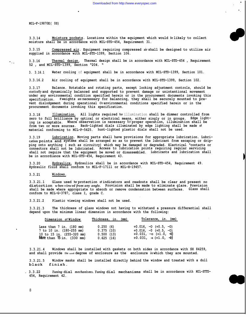
3.3.21.3 The thickness of glass windows not having to withstand a pressure differential shalldepend upon the minimum linear dimension in accordance with the following:
Dimension of Window Thickness, in. (mm) Tolerance, in. (mm) .
Less than 7 in. (180 mm) 0.250 (6) +0.016, -O (+0.5, -O)7 to 10 in. (180-255 mm) 0.375 (10) +0.016, -0 (+0.5, -O)10 to 15 in. (255-320 mm) 0.500 (13) +0.031, -o (+1.0, -o)More than 15 in. (330 mm) 0.625 (16) +0.031, -o (+1.0, -o)
3.3.21.4 Windows shall be installed with gaskets on both sides in accordance with SX 84259,and shall provide the same degree of enclosure as the enclosure in which they are mounted.
3.3.21.5 Window masks shall be installed directly behindblack finish.
. 3.3.22 Tuning dial mechanisms. Tuning dial mechanisms454, Requirement 42.
the window and treated
shall be in accordance
with a dull
with MIL-STTD-
8
Downloaded from http://www.everyspec.com

MIL-F-18870E(OS)
3.3.23 Miscellaneous parts. Miscellaneous parts shall be in accordance with table I andthe following subparagraphs. If more than one document is listed for a part, the most appro-priate one shall apply.
3.3.23.1 Flatted shafts for control knobs shall not be used unless the shaft is an integralpart of a standard partt such as a potentiometer, capacitor, or switch.
3.3.23.2 Gaskets shall be attached so as to prevent their displacement when the doorover them is removed.
or cover
Table I. MISCELLANEOUS PARTS
Parts Governing documents
Bearings MIL-STD-454, Requirement 6.
GearS and CamS MIL-STD-454, Requirement 48Dials and scales DUG 264831$ DWG
-264832, DWG 275109, or SK 87448Grommets MIL-G-3036, MIL-G-20699, or MIL-G-22S29Threaded fasteners MIL-STD-454, Requirement 12Shafts QQ-S-764, grade 416Springs MIL-STD-454, Requirement 41controls MIL-STD-454, Requirement 28O-rings MS9386, MS9388, Or MS28900Castings MIL-STD-454, Requirement 21Aluminum alloy castings QQ-A-591, QQ-A-596, or QQ-A-601 I
I
Materials. Materials used shall be in accordance with table XI and the followingsubparagraphs, If more than one document is Listed for a material, the most appropriate one3.3.24
shall apply..
Table II. MATERIALS
Materials
Flammable materialFungus-inert materialOrganic fibrous materialtic-resistant materialAdhesivesElectrial InsulatorsDesiccantsGaskets: For windows, doors and
CoversGaskets or packing material for hy-
draulic or pneumatic applicationsGaskets or packimg material for
other applicationsDissimilar metalsFerrous metals and alloysAluminum alloy bars, rods, and shapesAluminum alloy plates and sheetsAluminum alloy tubingBrassBronzeCopperCopper-beryllium alloyCopper-nickel alloyCopper-nickel-zinc alloyNickel-copper alloy (Monel)
MIL-STD-454, RequirementMIL-STD-454, RequirementMIL-STD-454, RequirementMIL-STD-454, RequirementMIL-STD-454, RequirementMIL-STD-454, RequirementMIL-D-3464MIL-G-1149, Class 2 or 3
MH-P-96 or MIL-G-5514 IMIL-G-1149, MIL-R-2765, MIL-P-5516, MIL-R-15624,ZZ-R-765, MIL-S-6855, class IL, or MIL-R-900MIL-STD-454, Requirement LMIL-STD-454, Requirement: MQQ-A-200 or QQ-A-225QQ-A-250/2, QQ-A-250/8, or QQ-A-250/11WW-T-700/2, WW-T-700/4, or WW-T-700/6QQ-B-613, QQ-B-626, QQ-B-637, or QQ-B-639QQ-B-728, QQ-B-750, QQ-C-390, or QQ-C-450QQ-B-825, or QQ-C-502QQ-C-530, QQ-C-533, or MIL-C-22087MIL-C-15726 or MIL-C-20159MIL-C-17112QQ-N-281, QQ-N-286, or QQ-N-288
1 or use only where ozone resistance is not necessary.— - - -
9
Downloaded from http://www.everyspec.com
MIL-F-18870E(OS)
3.3.24.1 Materials which produce toxic gases or are toxic themselves during normal equipmentoperation under anY environmental condition specified herein or in the procurement documentsinvoking this specification shall not be used: .
3.3.24.2required ,documents
3.3.25
a.b.c*d.e.f .
h.i.
3.3.25.1ing shall
a .b.c.d.
Unless specifically required, the following materials shall not betheir use shall be in accordance with the requirements herein and ininvoking this specification. See 6.2(i). - . .
.
Radioactive materialMercury and its compounds and amalgamsMagnesium and its alloysZinc alloy die castingsAdhesive tape, except when appropriate for coil-wrapping
Organic fibrous material .Plastic having cotton fabric base laminateCotton or wood flour filld molding compounds
Processes and procedures.
used. When sothe procurement
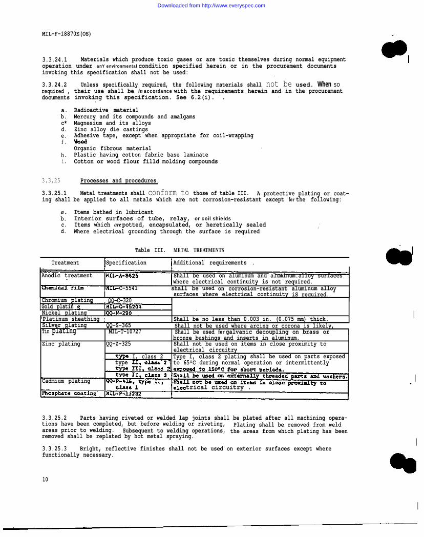
Metal treatments shall conform to those of table III. A protective plating or coat-be applied to all metals which are not corrosion-resistant except for the following:
Items bathed in lubricantInterior surfaces of tube, relay, or coil shieldsItems which are potted, encapsulated, or heretically sealed .
Where electrical grounding through the surface is required,
Table III. METAL TREATMENTS
Treatment Specification Additional requirements .
Anodic treatment Shall be used on aluminum and aluminum.alloy surfaces.where electrical continuity is not required.
C-5541 shall be used on corrosion-resistant aluminum alloy1 I surfaces where electrical continuity iS required. -
Chromium plating QQ-C-320 t IGold platinNickel plating
.
‘Platinum sheathing I Shall be no less than 0.003 in. (0.075 mm) thick.SiLver plating QQ-S-365 Shall not be used where arcing or corona is likely,Tin plating MIL-T-10727 Shall be used for galvanic decoupling on brass or I
bronze bushings and inserts in aluminum.Zinc plating QQ-Z-325 Shall not be used on items in close proximity to
electrical circuitryI, class 2 Type I, class 2 plating shall be used on parts exposed
type to 65°C during normal operation or intermittently
Cadmium platingtrical circuitry .
.
3.3.25.2 Parts having riveted or welded lap joints shall be plated after all machining opera-tions have been completed, but before welding or riveting, Plating shall be removed from weldareas prior to welding. Subsequent to welding operations, the areas from which plating has beenremoved shall be replated by hot metal spraying.
3.3.25.3 Bright, reflective finishes shall not be used on exterior surfaces except wherefunctionally necessary.
I
I●
I
10
I
Downloaded from http://www.everyspec.com

3 . 3 . 2 5 . 4 Painting shall be in accordance with MIL-STD-1303. The cleaning and preparation. offerrous metal and zinc-coated surfaces shall be in accordance with TT-C-490. Plastics shall notbe painted unless specifically required. See 6.2(j).
3 . 3 . 2 5 . 5 Porous plastics or plastics having porous surfaces after machini.ng shallbe coatedwith varnish conforming to MIL-V-173.
3 . 3 . 2 5 . 6 Structural welding shall be in accordance with MIL-STD-454, Requirement 13.
3.3.25.7 Brazing shall be in accordiance with MIL-STD-454, Requirement 59,
3.4 Optical design. Optical design shall be as specified in the procurement documentsinvoking this specification. See 6.2(k). Optical terms used herein are defined in MIL-STD-1241.
3.4.1 Rim edges. Rim edges of all optical parts shall have a chamfer of 0.020 to O.O15in. (0.5 to 0.35 mm) at 45° ±5 l.5O as measured along the face width. Edges meeting at anglesof 135° or more or edges forming a "roof" shall not be chamfered,
3.4.2 Reticles. Letters and numerals shall be fully legible. Stencil-type letters ornumbers shall not be used except for perforated retitles. Line breaks of no more than one-halfthe line width are acceptable. For retitles containing more than 15 lines, one break per fivelines or fraction thereof is acceptable. All lines shall appear of uniform width, and theintersections shall appear sharp. Hllet radii at the intersections of reticle lines shall notexceed the line width.
MIL-F-18870E(OS)
3.4.2.1 The brightness of any defect shall not exceed that of the illuminated reticle.
3.4.2.2 Parallelism of reticle flat surfaces shallbe within 5 minutes of arc (1.5 mrad) in “deviation of the light path. ●*
3.4*3 Optical element padding. Shims, wedges, or peening under or around optical elementsshall not be used unless specifically approved by the procuring activity. See 6.2(1).
3.4.4 Optical element defects. All polished surfaces shall be free of adhesions, grayness,scratches, pits, stains, or other defects that are visible in the field of view or which impairoptical performance ●
3,4.4,1 Scratches, digs, and bubbles shall not exceed the limits specified in MIL-O-13830.
3.4.4.2 Lenses may have edge chips which do not encroach upon the free aperture of the lens,provided the chips do not interfere with the sealing of the lens In the mount or increase thelikelihood of breakage. The surface of chips larger than 0.02 in. (0.5 mm) across their largest dimension shall be "stoned’ t to roughen them and lessen reflections and additionalchipping.
3.4.5 Diopter setting. Fixed-focus eyepieces shall have a diopter setting of -2.7 ±3 0.3.
3 . 4 . 6 Resolution, visual, In the center of the field, the limit of resolution, defined asthe angle separating the centers of the mostthrough the optical system, shall not exceed
closely-spaced-lines seen separately and distinctlythe greater of:
a. 60 divided by the magnification ofb. 145 divided by the diameter of the
the diameter of the entrance pupilentrance pupil-in millimetresin inches)
( 5.7 divided byI
When the limit of resolution is measured in seconds of arc. If the limit of resolution ismeasured in microradians, it shall mot exceed the greater of:
a. 300 divided by the magnification of the instrument, orb. 700 divided by the diameter of the entrance pupil in millimetres (28 divided by
the diameter of the entrance pupil in inches).
Downloaded from http://www.everyspec.com

●
MIL-F-18870E(OS)
3.4.6.1 Unless the exit pupil of the instrument is leas than 0.05 in. (1.3 mm) in diameter,an auxiliary telescope shall be used between the eyepiece of the instrument end an observer'seye. The auxiliary telescope shall be of such magnification. that the exit pupil of the combina-tion is not greater than 0.05 in. (1.3 mm).
3.4.6.2 The optical system shall be free of visible chromatic aberration, coma, and astigma-tism. The loss of resolution at increasing angles from the center af field shall not be appar-ent When the eye is focused at the center of the field. Radial distortion of images shall notbe noticeable or cause the reticle divisions to fall outside the specified angular tolerance.
3.4.7 Resolution, photographic. The resolution of photographic lenses$ together withother Optical characteristics, shall be in accordance with the applicable requirements ofMIL-STD-l50.
3.4.8 Stray liqht. No stray or scattered light or reflections from surfaces within theoptical instrument shall be visible in the field of view or enter the exit pupil or be visiblein the vicinity of the exit pupil. All internal surfaces of parts from which stray or scatteredlight might be reflected shall be treated to avoid such reflections, and darkened in accordancewith MIL-P-18317. .
.
I..
3.4.9 Line of sight shift (LOSS). Variable focus optical instruments having cross-lineretitles or the equivalent and designed to focus on objects between optical infinity and shortdistances (e.g., a few hundred yards and a few feet) shall be designed for a minimm value of LOSS, commensurate with operational requirements. The value of LOSS shall not exceed the valuespecified in the procurement documents invoking this specification. See 6.2(m)..
3.4.9.1 LOSS is defined as the change in the line of-sight direction as the instrument focusis changed with the instrument otherwise fixed in position. There is a line of sight,. definedas the imaginary line between the center of the reticle and Its projection on the object planet
for each object distance between optical infinity and the minimum focus distance. ID an idealinstrument, all these lines Would be colinear. In real instruments, the mechanism for accom-plishing a change In focus is less than perfect, with the result that each line of sight is ina slightly different direction. One line of sight is taken as the reference, and the angle thatany other line of sight ‘makes with the reference is the LOSS for that object distance. Usuallythe reference line of sight is that for the shortest focus distance.
3.4.9.2 The reference line of sight shall be as specified in the procurement documentsinvoking this specification. See 6.2(n).
3.4.9*3 The optical instrument shall include one or more external reference surfaces or theequivalent to permit testing the instrument for LOSS in accordance with the method specifiedherein or in the procurement documents invoking this specification. See 6.2(0). At least onesuch surf ace or its equivalent shall be provided to insure that as the instrument is rotatedthrough its range, the optical center of the objective lens or the equivalent remains coincidentwith the axis of rotation. The design pertaining to the external reference surfaces or equiva-lent and their function in testing fur LOSS shall be as specified in the procurement documentsinvoking this specification. See 6.2(p). ,
3.4.10 Reflecting surfaces. ..
3.4.10.1 First surface reflectors on glass or other dielectric shall be of evaporated alumi-num or equivalent. There shall be no visible discontinuities that adversely affect the field ofview as seen with the eye in the normal viewing position. First surface mirrors shall be pro-tected by an overcoat of silicon monoxide free of holes, foreign matter, or perceptable varia-tions in density. A magnesium fluoride protective coating of equivalent uniformity may be used,when approved by the procuring activity, if silicon monoxide is impractical. See 6.2(q). Coat-ings shall be in accordance with MIL-M-13508. The white light reflectance of any first surfacereflector shall be not less than 87.5 percent.
3.4.10.2 The backing for a first surface reflector shall be optical glass or annealed heat-resistant glass having a low coefficient of thermal expansion.
.3.4.10.3 Coated internal reflecting surfacs shall be chemically deposited silver. Such sur-faces cm the outside of a prism or mirror shall be backed with copper and an outer black finish.
12
Downloaded from http://www.everyspec.com

MIL-F-18870E(OS)
The uniformity of the surface shall be such as to cause no discernible unevenness in the fieldof view.
3.4.10.4 Partially reflecting surfaces shall be of evaporated aluminum titanium dioxide orequivalent material. When evaporated aluminum is used, the surface shall be protected as speci-fied for first surface reflectors.
3.4.11 Cleanliness. The optical surfaces shall be clean and free of condensates and vola-tile substances.
3.4.12 Lubricants. Lubricants and dust retention greases shall not be used in opticalinstruments.
3.4.13 Lens caps. Caps shall be provided for exposed lenses and windows.
3.4.14 Filters, optical. Optical filters shall not alter the line of sight alinement bymore than 30 percent of its specified tolerance.
3.4.14.1 Color filters shallbe in accordance with MIL-F-21241 and shall be selected fromthose listed on SK LD132263.
3.4.14.2 Polarizing filters shall be in accordance with MIL-F-21424 and shall be selectedfrom those listed on Drawing 230989.
3.4.1403 Variable density filters shall consist of an assembly containing both a fixed and arotatable polarizing filter. A clear glass correction plate shallbe positioned in the line ofsight when the filter assembly is rotated out of the field, if necessary to avoid refocusingwhen changing from “clear” to variable density”. In the filter assembly the rotatable polariz-ing filter shall be nearer to the eye. When the planes of polarization of the two plates in theassembly are parallel, this common plane shall be oriented so as to:
a. Reduce surface glare in the target field to a minimum if there are no optical elementsbetween the fixed polarizer and the target which cause nonuniformity in the illumination of theexit pupil as a result of rotation of the plane of polarization, or
b. Reduce surface glare and produce a uniformly illuminated exit pupil when the incidentlight is plane-polarized in the horizontal or vertical plane and if then is an optical elementbetween the fixed polarizer and the target which causes nonuniformity in the illumination ofthe exit pupil as a result of rotation of the plane of polarization.
3.4.14.3.1 A single-knob control shall be provided for variable density filters. Rotation ofthe knob shall move the filter into and out of position for use and shall also adjust the den-sity of the filter between maximum and minimum. An overrun of approximately 5° at each endshall be provided. When the knob is rotated to remove or insert the clear correction plate, thepolarizer pair shall be oriented at minimum density.
3.4.15 Optical materials.●
3.4.15.1 Optical glass shall be in accordance with MIL-G-174.
3.4.15.1.1 Window glass for use with telescopes shall be parallel to within 1 minute of arc(0.3 mrad), equivalent to 30 seconds of arc (0.15 mrad) image deviation, with a surface figureof not over one fringe for dimensions up to 6 in. (150 mm) and not over one fringe for any cir-cular area up to 6-in. (150-mm) radius.
3.4.15.2 Transparent plastics shall not he used in optical systems except for reticle illumi-nators,
3.4.15.3 Etch optical surface shall be coated with a reflection-reducing film in accordancewith MIL-C-675, with the following exceptions:
a. Surfaces in a focal plane.b. Surfaces of elements bearing reticle graduations.c. Surfaces to be cemented.d. Reflection surfaces (including total internal reflection surfaces).
Downloaded from http://www.everyspec.com
MIL-F-18870E(OS)
●
e. Suraces exposed to the action of a window wiper.f. Color, neutral. or polarizing filters.
●
3.4.15.4 Cement used for optical instruments shall be thermosetting adhesive in accordanceWith MIL-A-3920, Canada Balsam in accordance with MIL-C-3469g cellulose caprate, or epoxy type,as specified in the procurement documents invoking this specification. See 6.2(r). Epoxy
“. cements or similar compoundS may be used to support parts within replaceable assemblies. . The“.. cement film binding optical elements shall be free of ford particles, bubbles, cement starts, “
milkiness, or other defects which reduce the effectiveness of the optical instrument. Excesscement shall be ,removed from the exterior of parts. No reagent shall be used which could beabsorbed into the cement film and cause cement starts or other defects, or subsequent deteriora-tion of the cement film.
3.5 Electrical design.
305.1 Standard Hardware Program. The design of fire control equipment shall enploy theStandard Hardware Program to the maximum practicable extent, in accordance with MIL-STD-1378.Electronic modules used or developed for use with the Standard Hardware program shall be inaccordance with MIL-STD-1389. and MIL-M-28787.
I 3 . 5 . 2 Electromagn etic compatibility. The equipment shall be in accordance with MIL-STD-454, Requirement 61 and MIL-STD-1399, Sections 401, 408, and 409. See 6.2(s)..
3 . 5 . 3 Grounding and shielding.
I
3*5.3.1 Neither the chassis nor the enclosure shall be used as a circuit” ground. Allgrounds within a subassembly or component shall be routed to a single common ground connectionwithin the respective subassembly or component. The ground terminal of each subassembly or com-ponent shall be routed to a common ground connection the the enclosure which, in turn, will berouted to the ship structure. Multiple ground terminals on terminal boards and individual
. . grounding of transmission line shields are permissible.
3.5.3.2 Bonding straps of braided or woven copper wire, or a solid strap, shall be providedto bond all enclosures electrically to the ship structure. The method used shall be uniform-.,throughout the equipment.
3.5.3.3 Devices affected by magnetic fields, such as cathod-ray tubes, shall be suitablyshielded to minimize the effects of such fields likely to be encountered at the service locationof the equipment.
3.5 .3 .4 The number of mechanical discontinuities in the enclosures shall be minimized. Alldiscontinuities,. such as covers and doors, shall be electrically continuous across the disconti-nuity. Multiple-point, spring-loaded contacts are a desirable method of obtaining low impedanceelectrical continuity. Electrical bonding shall be provided where access doorszw or cover platesform a part of the shielding. Hinges, in themselves, are not acceptable as electrical bonds.The mating surfaces of the chassis, enclosure and mounts shall be free of insulation in orderto allow a continuous electrical bond between these items and to enable the installing activityto accomplish bonding contact.
.3.5.4 Electrical power sources.
●. 3.5.4.1 Unless otherwise specified, the equipment shall be designed to utilize a 440-volt,3-phase, 60 Hz power source in accordance with MIL-STD-1399, Section 103. See 6.2(t).
.3.5.4.2 The use of batteries shall be in accordance with MIL-STD-454, Requirement 27.
3.5 .4 .3 Electrical power plugs and receptacles shall be in accordance with MIL-R-2726 andshall be identified to indicate the type of power involved.
3,5.5 Electrical power source loading. When power with alternating current as specifiedherein, the equipment, in any normal operating mode, shall draw nO current at any frequency be-tween the 2nd and 23rd harmonic at an amplitude greater than 3 percent Qf the rated load currentand nO current at any frequency between the 23rd harmonic and 20KHz at an amplitude greaterthan 1700/n2 percent of the rated load current, where n is the order of the harmonic..
14 -
Downloaded from http://www.everyspec.com

● ✌✎
✌
MIL-F-18870E(OS)
3.5.6 Warmup. The equipment shall be designed to reach stable operation after no morethan 30 minutes of warmup time when supplied with the specified input power under anY environ- .mental situation specified herein or in the procurement documents invoking this specification.
3.5.7 Circuit and component protection.
3.5.7.1 Electrical overload protection shall be in accordance with MIL-STD-454, Requirement 8.
3.5.7.2 . Where practicable; circuit breakers in accordance with MIL-STD-454, Requirement 37,. shall be used in lieu of fuses, A circuit breaker shall not be used as a switch.
3.5.7*3 Fuses, fuseholders, and associated hardware shall be in accordance with MIL-STD-454,Requirement 39. At least one spare fuse of each type and rating used in the equipment shall beprovided and secured in an easily-accessible location, and identified in an appropriate manner.
3.5.7.4 Electronic circuits that would be damaged by the application of operational voltageswithout a sufficient warmup period shall include circuitry to delay the application of such vol-tages after primary power is applied.
3.5.7.5 Electronic parts and materials which are to operate at temperatures above ambientshall be appropriately derated in accordance with MIL-STD-454, Requirement 18.-
3.5.7.6 Corona and electrical breakdown prevention shall be in accordance with MIL-STD-454,Requirement 45.
3.5.8 Wiring practices.
3.5.8.1 Stuffing tubes shall be used where applicable to preserve the degree of enclosure atthe point of entry of each cable. All stuffing tubes for an enclosure shall be mounted on aplate having enough spare area to accommodate an additional stuffing tube of the largest sizemounted thereon. This plate shall be on either of at least two sides of the enclosure. Theunused stuffing tube mounting plate areas on the enclosure shall be covered with blank plates ofthe same configuration as the stuffing tube plate.
3.5.8.2 The equipment shall be equipped with suitable provisions for interfacing properlywith data input and communication facilities at the service location, and shall be in accor- .dance with MIL-STD-1399, Sections 502 and 505. See 6.2(u).
3.5.8.3 Internal wiring practices shall be in accordance with MIL-STD-454, Requirement 69.
3.5.5.3.1 Neither side (Or phase) of the input power line shall be used as an enclosure orcircuit ground. All shipboard AC power is electrically "floating"
3.5.8.4 Synchro wiring shall be in accordance with
3.5.8.5 Printed wiring shall be in accordance with
3.5.9 Mounting of parts.
3.5.9.1 Cathode-ray indicators shall be mounted so
MIL-STD-1399, Section 702.
MIL-STD-454, Requirement 17.
the visual axis, during normal operation,is perpendicular to the face of the indicator at its center.. Range rings, angular bearing lines,and and markings shall be easily definable and shall be spaced in accordance with accuracyrequirements. Background brightness and surface reflections shall be minimized and viewing “hoods provided in high ambient light areas..
3.5.9.2 Circuit and terminal boards shall be mounted in such a manner that no relative move-ment between the board and frame occurs during normal operation, Circuitryand parts on circuitboards shall clear all frame parts and other boards by a suitable distance for the voltagesinvolved. Replaceable boards shall be provided with a means of removal which allows removalwithout damage to board, frame, or parts mounted on the board. Circuit boards shall not besecured solely by connectors.
3.5.9.3 Electronic or electrical partS shall not be mounted on other electrical parts. Partbinds, at terminals or elsewhere, shall not be connected directly to other part leads. Part
*
15
Downloaded from http://www.everyspec.com
MIL-Ff-18870E(OS)
.
weighing more than one-half ounce (15 grams) shall be supported by
3.5.9.4 Readouts and meters shall be removable from the frontmounted and their leads shall be long enough to allow removing thedisconnecting it.
3.5.9.5 Each part, module, Or assembly which maybe removed orvicing or maintenance shall be mounted wing electrical connectorsnondestructive disconnection and reconnection.
means other than their leads.
of the panel in which they arereadout or meter without
replaced during normal ser-and hardware which allows
3.5.9.6 Indicator lamps and fuses shall be replaceable from the front of the panel in whichthey are mounted. .
●
3.5.10 Potting, impregnation, and encapsulation.
3.5.10.1 All enclosed coils end transformer windings shaLl be potted to insure positionalstability, except when electrical characteristics would be adversely affected. Prior to pot-ting, the coils shall be treated to remove moisture and foreign substances.
3.5.10.2 All coils and windings except those which are potted or are contained in hermet-ically sealed cases shall be dried and impregnated with insulating varnish. The varnish shallcompletely cover. the wiring wrapping, and coil form to create en unbroken film.
3.5.10.3 Encapsulatlm and embedment (potting) shallbe in accordance with MIL-STD-454,Requirement 47.
●
3.5.11 Electrical interconnections..
.●
3.5.11.1 Electrical soldering shall be in accordance with MIL-STD-454, Requirement S...3.5.11.2
.Resistance welds for electrical interconnections shall be in accordande with
MIL-STD-454, Requirement 24. .
3.5.12materialslowing:
a.b.
c.
3.6following
3.6.1
Electrical and electronic Parts and materials. Electrical and electronic parts andshall be in accordance with the appropriate documents listed in table IV, and the fol-
Fluorescent lamps shall not be used as indicators.Operating time meters shall be incorporated as specified in thedocuments invoking this specification. See 6.2(v). .Synchros shall be in accordance with MIL-STd-1399, Section 702.
procurement
Marking. Marking shall be in accordance with MIL-STD-454, Requirement 67 and thesubparagraphs.
Symbols and terminology. symbols and terminology shall beOP 1700 and MIL-STD-1399, Section 501.
in accordance with
3.6.2 Dials and scales.
3.6,2.1 Dial and scale markings shall be direct reading and shall not require the use ofcalibration curves or conversion charts.
3 . 6 . 2 . 2 Dial and scale markings shall be in accordance with MIL-STD-725.
3.6,2.3 Where verniers are employed to subdivide scale divisions, the marking and numberingshall have continuity throughout the dial range.
3.6.2.4 Dials and sales shall be mounted so that at least three identifying graduationsymbols are visible at any setting or reading. .
3.6.3 Optical elements. Optical elements cemented with cellulose caprate shall be marked‘CC” on the edges.
.
Downloaded from http://www.everyspec.com

MIL-F-18870E(OS)
Table IV
Electrical and Electric Parts and Materials
Part or material Governing document ,
Electron tubes MIL-STD-454, Requirement 29Semiconductor devices ● MIL-STD-454, Requirement 30Microelectronic devices MIL-STD-454, Requirement 64Resistors . MIL-STD-454 , Requirement 33Shunts MIL-STD-454, Requirement 40Capacitors MIL-STD-454, Requirement 2Transformers, inductors, and coils MIL-STD-454, Requirement 14Transformers, synchro overload MIL-T-16387Coils, deflection and focusing, CRT MIL-C-18388Solenoids MIL-S-4040Relays MIL-STD-454, Requirement 57Switches MIL-STD-45S4, Requirement 58Controllers and master switches MIL-C-2212Electrical connectors MIL-STD-454, Requirement 10Sockets, shields, and clamps . MIL-STD-454, Requirement 60Convenience power outlets W-C-596Terminals, terminal boards, and terminal strips MIL-STD-454, Requirement 19Clamps and supports, cable OD 13726 and BuSHIPS STD 9000-S6202-73980Clamp, cable entrance, nonwatertight W-F-406Crystal units, quartz MIL-STD-454 , Requirement 38Filters, electrical MIL-STD-454, Requirement 70Motors, dynamotors, rotary power converters, and MIL-STD-454, Requirement 46
rotor generatorsRotary servo devices MIL-STD-454, Requirement 56Gyroscopes, rate integrating MIL-G-81168Meters, electrical indication, and accessories MIL-STD-454, Requirement 51Readouts MIL-STD-454, Requirement 68Indicator lights MIL-STD-454, Requirement 50Filters , indicator lamp MIL-P-5425Waveguides and related equipment MIL-STD-454, Requirement 53Wire, magnet J-W-1177wire, hookup, internal MIL-STD-454, Requirement 20Cable, multiconductor MIL-STD-454, Requirement 66Cable, multiconductor, interconnecting MIL-STD-454, Requirement 71
between unitsCable, coaxial (RF) MIL-STD-454, Requirement 65Cable, nonflexing MIL-C-21609 and OD 13726
3.6 .4 Lubrication points. Lubrication points shall be marked as such.
3.6. S Motor rotation. Motors shall be marked in a permanent manner to indicat e thedirection of rotation. Bidirectional motors shall be identified as bidirectional.
3.6.6 Interior wires. Except for jumpers on a termimal strip or connector, each wirewithin an enclosure Or unit of the quipment shall be uniquely identifiable. Interior wiresshall be identified by one of the following methods:
Having the wire designation printed on the wire at intervals along its entire length,b. Being color-coded along its entire length, ora. Having appropriately marked white plastic sleeves over the wire at each end.
3.6.6.1 when method a or c is used, the Identification shall consist of the terminal desig-nations for the two points connected by the wire, The marking shall be arranged so that thedesignation of the terminal to which an and of the wire is connected is closest to that and.Intrasystem wiring and cabling connecting equipment under the cognizance of the same Navall Com-mand, within the same compartment, mount, or directors and where the cable length Is no greaterthan 50 feet (16 metres), shall be identif ied by method C.
I
1 7
Downloaded from http://www.everyspec.com
“.“ .
MIL-F-18870E(0S)
3.7 Nomenclature. The nomenclature for fire control equipment shall be in accordancewith OR-1.
3.8 Environmental requirements. Fire control equipment shall be designed to withstandthe environmental conditions specified herein, in the procurement documents invoking this speci-fication, and in MIL-STD-1399, Sections 301 and 302, without damage or performance degradationbeyond specified tolerances See 6.2(w).
3.8.1 Temperature, ambient, operating. The equipment shall operate normally at any ambi-● nt temperature in the operating temperature range specified after a warmup period of no morethan 30 minutes. See 6.2(x). .
3.8.2 Temperaturel storage nonoperating. The equipment shall not be damaged nor its per-formance degraded after exposure to any temperature between -62
0C and 75°C for a period of notless than 72 hours, or by exposure to a temperature change of 135°C over a period of 10 minutes.
3.8.3 Altitude, nonoperating. The equipment shall not be damaged nor its performancedegraded after exposure to an altitude of 60,000 feet (18 km) for not less than 8 hours.
3.8.4 Sea pressure (submarine). Any part, accessory, or structural member of an equipmentintended for submarine use which may be exposed to external sea pressure shall be capable ofwithstanding a continuous hydrostatic pressure of 700 pounds per square inch (4.9 HPa) withoutdamage or leakage, and shall be in accordance with the submersible enclosure requirements ofMIL-STD-108. .
3.8.5 Shock, mechanical. The equipment shall not be damaged nor its performance degradedafter being subjected to the Grade A shock tests of MIL-S-901, as applicable for the particularequipment specified. See 6.2(y).
3.8 .6● xposure tospecified.
3 . 8 . 7exposure to
3.8.8of not less
Vibration. The equipment shall nut be damaged nor its performance degraded during.
the vibration tests of MIL-STD-167, as applicable for the particular equipmentSee 6.2(z). .
Salt atmosphere. The equipment shall not be damaged nor its performance degraded bythe “salt atmosphere" . associated with sea water.
Ice load. Equipment exposed to the elements shall operate normally with an ice loadthan 4.5 pounds per square foot (22 kg/m2) on all surfs-s subject to the formation
of ice. See 6.2(f). -
3.8..9 Wind load. Equipment exposed to the elements shall not be damaged by winds of up to100 knots (50 m/s), and shall operate normally during exposure to winds of not less than 75knots (40 m/s). See 6.2(f).
3 .8 . 10 Solar radiation. Equipment exposed to the sun at its service location shall not bedamaged nor its performance degraded by exposure to solar radiation as defined in MIL-STD-210.See 6.2(f).
3.9 Life , operating. The equipment shall operate normally without the need for mainte-nance for not less than 200 continuous hours. The equipment should be designed to have a mini-mum operating life of 12,000 hours, given normal maintenance.
3.10 Workmanship. Workmanship shall be in accordance with MIL-STD-454, Requirement 9.
4 QUALITY ASSURANCE PROVISIONS
4.1 Responsibili ty for inspection. Unless otherwise specified in the contract or pur-chase order, the supplier is responsible for the performance of all inspection requirements asspecified herein. except as otherwise specified in the contract or order, the” supplier may usehis own or any other facilties suitable for the performance of the inspection requirementsspecified herein, unless disapproved by the Government. The Government reserves the right toperform any of the inspections set forth in the specification where such inspections are deemednecessary to assure supplies and services conform to prescribed requirements.
18 .
●
Downloaded from http://www.everyspec.com
●
✎
✎
4.2
a.b.
4.3following
4.3,1.
a.b,c*
MIL-F-18870E(OS)
.
Classification of inspections. Inspections specified herein are of two types:
First article inspection. See 4.4Quality conformance inspection. See 4.5
Inspection conditions. Unless otherwise specified, the conditions specified in thesubparagraphs shall exist during inspections.
Ambient conditions. .
Temperature: 25° ± 5°CHumidity: 55 ± 30 percent relativePressure: normal atmospheric
4.3.2 - Attitude. The equipment shall be tested in the attitude it would assume at its ser-
vice location on a calm sea. See 6.2(f)..
4.3.3 Power. The equipment shall be supplied with electrical power from a source capableof supplying full load current at nominal voltage and frequency. The power source shall main-tain its output voltage within 2 percent of nominal and its frequency within O.1 percent ofnominal under all load conditions. When supplying full had current, the power source outputshall have a harmonic voltage content at any harmonic from the 2nd to the 23rd not exceeding0.75 percent of the fundamental and from the 23rd harmonic through 20kHz not exceeding425/n 2 percent of the fundamental, where n is the order of harmonic. See 6.2(t).
4.4 . First article inspection..
4 . 4 . 1 Samples. Each first article shall be inspected. See 6.2(b). ,.
4.4.2 Procedure. Unless otherwise. specified, the first article samples shall be sub-jected to the first article inspection of table V in the order listed and using the test proce-dures specified therein. See 6.2(aa).
4.4.3 Failures. The failure of any first article sample to meet any requirement specifiedherein shall-e for denial of production approval.
4.5 Quality conformance Inspection.
4.5.1 Samples. Unless otherwise specified, each fire control equipment submitted foracceptance shall be inspected (100 percent inspection). See 6.2(ab).
4 . 5 . 2 Procedure. Unless otherwise specified, the quality conformance samples shall besubjected to the quality conformance inspection of table V In the order listed and using thetest procedures specified therein. See 6.2(ac).
4.5.3 Failure of a sample. The failure of a quality conformance inspection sample to meetany requirement specified herein shall be cause for rejection of that sample and may be causefor revocation of production approval.
4 . 6 Test procedures.
4.6.1 Preparation for delivery. The material and procedures used to prepare the equip-ment for delivery shall be examined for conformance to the requirements of section 5 herein.
4.6.2 Size. Each equipment enclosure shall be measured to determine conformance to therequirements of 3.3.10.
4.6.3 Weight. Each equipment enclosure shall be weighed and examined to determine con-formance to the requirements of 3.3.11.
3 herein and in the procurement documents invoking this Specification. see 6.2(C). Assembledequipment shall be prepared for this examination by being exposed as for servicing, With all
19
Downloaded from http://www.everyspec.com

Table V
EXAMINATIONS AND TESTS
Name of examination or
test and requirement,, Preparation for delivery
“ . . SizeWeightConfiguration t parts, materials
armup, electrical. . erformance, detailed
Performance, overall -
oise, acousticallectromagnetic compatibilityower source loading
Power source variationsAltitudeShock, mechanicalVibrationTemperature, storageTemperature, operatingHumiditySalt atmosphereSea pressuregree of enclosure
erformance, overall
..
her specified testsperformance, detai led
“.
L ilar radiationfe, operating
b
Requirement
3.3.103.3.3.13.3 to 3.7,3.10, 6.2(c)3.5.66.2(c)6.2(c)3.3.123.5.23.5.53.5.4.13.8.33.8. S3.8.63.8.23.8.13.83.8.73.8.43.3.13.16.2(c)3.8.83.8.93.86.2(ag)6.2(c)3.8.103.9
Method”
4.6.14.6.24.6.3
4.6.44.6. S4.6.6.14.6.6.24.6.74.6.84.6.94.6.104.6.114.6.124.6.134.6.14 .4.6.154.6.164.6.174.6.384.6.194.6.6.24.6.204.6.214.6.224.6.234.6.6.14.6.244.6.25
Order of exaFirst article
12
345
789
1011 121314151617181920212223242526
inations and testsQuality conformance
1
2 “3
45
67
..
doors, panels, covers, chasses, assemblies, and modules opened, removed, or exposed, as appro-priate for a thorough visual examination.
4.6. S Warmup , electrial. The equipment shall be energized with electrical power asspecified in 3.5.4, us ing a power source specified in 4.3.3, shall be allowed to warm up for35 ± 5 minutes, and shall then be monitored for overall performance in accordance with 4.6.6.2.
4 . 6 . 6 Perform a n c e t e s t i n g . Performance, or operational, testing shall be performed whenrequired to deteermine whether the equipment is capable of accomplishing its intended purpose.
4.6.6.1 Performance, detailed. The equipment shall be operated using all modes, settings,and ranges of its controls and input signals necessary to determine conformance to the specified
. performance requirements. See 6.2(c), (u). For this test, input signals typical of those which. would be received in service shall be supplied, and shall include enough variety to exercise allspecified equipment functions. Equipment output signals and internal parameters shall be moni- .tored to determine proper operation. The test procedure shall be as specified in the procure-ment documents invoking this spcification. See 6.2(k), (o), and (ad).
4.6.6.2 Performance, overall. This test is intended to indicate the occurrence of opera-.tional damage or impairment as a result of testing. This test should be simple and easy to setup, and should be in the form of continuously monitoring critical parameters whose deviationfrom tolerances would indicate impending or actual failure. See 6. 2(ae).
4.6.7 Noise, acoustical. The equipment, operating in its loudest mode, shall be moni-tored for acoustic noise level in. accordancs with MIL-STD-740.
20
●
✌
Downloaded from http://www.everyspec.com
.
4.6.8 Electromagnetic compatibility.emissions and susceptibility in accordance
1
Thewith
MIL-F-18870E(OS)
.
equipment shall he tested for electromagneticMIL-STD-454, Requirements 61. See 6.2(s).
4.6.9 Power source loading The equipment shall be operated in the the producing thehighest input voltage harmonics. while supplied with power from a source in accordance with 4.3.3 ●
herein. The harmonic voltage content of the input power shall be determined at all frequenciesup to 20 KHz. ..4.6.10 Power source variation. The equipment shall be supplied with power from a source. ●
capable of providing the variations specified herein, shall be allowed to warm up, and shall besubjected to the overall performance test of 4.6.6,2. The power soure shall then be varied asdescribed herein for a period of not less than 6 hews, during which time the overall performanceof the equipment shall be monitored in accordance with 4.6.6.2. Each characteristic being variedshall continue for the remainder of the test in the Varying condition .The Variations fromnominal specified herein represent deviations to be expected from shipboard power supplies, endare described in MIL-STD-1399, Section 103. When the following procedures refer to “limitsspecified”, the limits specified in MIL-STD-1399, Section 103 shall be utilized,
4.6.10.1 The line-to-line voltage shall be continuously cycled between the limits specified,each cycle taking 4 + 0.5 minutes, The cycling shall continue for not less than one hour.
4.6.10.2 At the start of the second hour an unbalance, of the limits specified, shall beintroduced between phases. Single-phase power is exempt from this portion of the test. Thisphase unbalance shall continue for not less than one hour..
4.6.10.3 At the start of the third hour, amplitude modulation of the limits specified shallbe included, and shall continue for not less than one hour. ..
4 .6 .10 .4 At the start of the fourth hour, the frequency shall be cycled between the limitsspecified, each cycle taking 3 + 0.5 minutes. This cycling shall continue fur not less thanone hour. .
4.6.10.5 At the start of the fifth hour, transients of the type and limits specified shall beintroduced once every 5 + 0.5 minutes. A total of thirteen such transients shall be epplfed.
4.6 .10 .6 At the start of the sixth and last hour, the sinusoidal waveform of the power sourceshall be distorted to the limits specified, and the distortion shall continue for not less thanone hem.
4.6.11 Altitude. The equipment, not energized, shall be subjected to reduced atmosphericressure (55 mm HG or 7.3 k pa) corresponding to an altitude of not less than 60,000 feet (18 km)for not less than 8 hours, and shall then be examined for mechanical damage.
4.6.12 shock mechanical. The equipment, not energized, shall be subjected to applicableshook testing in accordance with MIL-S-901, and shall then be examined for mechanical damage,See 6.2(y).
4.6.13 Vibration. The equipment shall be energized and allowed to warm up in accordancewith 4.6.5, ‘1 be monitored for overall performance in accordance with 4.6,6.2 for theduration of this test. The operating equipment shall be subjected to type I vibration testing
. ● applicable to the equipment in accordance with MIL-STD-167, and shall then be examined formechanica1 damage. See 6.2(z).
4.6.14 Temperature, storage. The unenergized equipment shall be placed in a temperaturechamber Maintained at -62° t 0°, -5°C for not less than 72 hours. After this cold storage, theequipment shall be transferred to a temperature chamber maintained at 750 + 30c. The transfershall be completed within 10 minutes. The equipment shall remain in the hot chamber for not lessthan 72 hours.
4.6.34.1 After the 72-hour hot storage period, the equipment Shall again be transferred,within 20 minutes, to the cold storage chamber of 4.6.14, where it shall remain for not lessthan 4 hours. In this manner, the cold-hot cycle shall be repeated four times after the initial144-hour cycle , except that the repeated cycles shall consist of not less than 4 hours at ● ach temperature extreme.
21
Downloaded from http://www.everyspec.com
● MIL-F-18870MOS)
4.6.14.2 At the conClusion of this test, the equipment shall have been in cold storage fornot less than 88 hours, in hot storage for not less than 88 hours, and will have been transfer-red from one to the other nine times. After the last 4-hour hot storage period, the equipmentshall be returned to room temperature and left for not less than 4 hours before further testing.
4.6.15 Temperature, operating. The equipment shall be placed in a temperature chamber atroom temperatures energized and warmed up in accordance with 4.6.5, and shall be miteredfor overall performance in accordance with 4.6.6.2 for the remainder of this test.
4.6.15.1 The temperature shall be lowered in 10° + O.5O C increments every 30 +_ 5 minutesuntil the lowest specified operating temperature +0°, -5° C is attained. This temperature shallbe obtained for not less than 24 hours. See 6.2(x).
4.6.15.2 The temperature shall then be raised in 100 + 0.5° C increment every 30 + 0.5 min-utes until the highest specified operating temperature +0°, -So C is attained. This temperatureshall be maintained for not less than 4 hours. See 6 .2(x) .
4.6.15.3 The tempature shall then be lowered in 10° + 0.5° C increments every 30 + 5 min-utes until room temperature is attained, after which the equipment shall be operated for notless than 4 hours.
4.6.16 Humidity. .
4,6.16.1 The equipment, exposed as for servicing and not energized, shall be dried for notrvless than two hours at a temperature of 450 + 5° C and at relative humidity not exceeding 30percent in a suitable temperature-humidity chamber.
4.6.16.2 The equipment shall then be securedd for normal operation, shall be energized andwarmed up in accordance with 4.6.5, and shall be monitored for overall performance in accordancewith 4.6.6.2 for the remainder of this test. ..
4.6.16.3 The equipment shall be subjected to five temperature-humidity cycles as follows:
a. The temperature shall be raised gradually for 1.3 + 0.2 hours to 60° + So C or themaximum specified operating temperatures whichever is lower, and maintained for not less then16 hours. See 6.2(x). During the 16-hour period, the relative humidity shall be not less than.95 percent.
b. The temperature shall then be lowered gradually for 1.3 + 0.2 hours to 30° + 50 C, andmaintained for not less than 8 hours. During the 8-hour period3 the relative humidity shall benot less than 95 percent.
4.6.16.4 The temperature shall then be raised gradually for 0.8 + 0.2 hour to 50° + 50 C orthe maximum specified operating temperature, whichever is lower, and maintained for not lessthan 8 hrs. See 6.2(x). During the first 2 + 0.2 hours of the 8-hour period, the relativehumidity shall be 5O + 5 percent. For the following 4 + 0.3 hours, the relative humidity shallbe not less than 90 percent. During the reading the, the relative humidity shall be 40 + 5percent.
4.6.16.5 At the conclusion of the test, the equipment shall be exposed as for serrvicing, andshall be examined for evidence of corrosion, deterioration, or damage caused by condensation.
4.6.17 Salt atmosphere. A salt spray test in accordance with ASTM Bl17-64 shall be pe-formed on frames and enclosure of the equipment. Only one of similar frames or enclosures needbe tested. The test duration shall be 200 hours.
4.6.18i ~
Pressure tests as specified in the procurement documents invokingthis specif~cat on shall be conducted on the equipment, as applicable. See 6.2(af).
4.6.19 Degree of enclosure. The degree of enclosure shall be determined in accordance withMIL-STD-108.
4.6.20 “ Ice load. The surfaces of the equipment subject to ice loading shall be ice-loadedor treated to simulate ice weight, thickness, and temperature, to no less than 4.5 pounds per
22.
●
Downloaded from http://www.everyspec.com
l!IL-F-18870(OS)
square foot (22kg/m2). The equipment shall then be energized and warned up in accordance with4.6,5 and its performance monitored in accordance with 4.6.6.2, The equipment shall also beexercised as applicable to determine ifthe ice loading has damaged the equipment or restrictedits moments beyond tolerances. See 6.2(c) and (f)*
.4.6.21 Wind load. Equipment components subject to wind loads shall be wind-loaded ortreated to simulate a wind load of not less than 100 knots (5O m/s) for 5 + 1 minutes in each-offour directions 90° + 5° apart. The wind load shall then be decreased to 75 + 5 bets (40 m/s),and the test repeated. The equipment SW have been energized and warned up in acccmlance with4.6.5 and shall have its overall performance monitored in accordance with 4.6.6.2 during the75-knot test. The 75-knot wind shall be maintained in each of the four directions long enoughto exercise the equipment and detect any damage Or restrictions of movement beyond tolerancesspecified. See 6.2(c) and (f). .
4.6.22 Attitude. The equipment shall be energized and warmed up in accordance with 4.6.5and monitored for overall. performance in accordance with 4.6.6.2 for the remainder of this test.The equipment shall be subjected to the maximum roll angle and rate for its intended servicelocation in accordance with MIL-STD-1399, Section 301, for not less than 2 hours. The testshall then be repeated with the roll axis rotated 90° in the horizontal plane. See 6.2(f).
4.6.23 Other tests. The equipment shall be subjected to other test procedures as specifiedin the procurement documents invoking this specification. See 6.2(ag).
4.6.24 Solar radiation. The equipment shall be warmed up in accordance With 4.6.5 andshall be monitored for overall performance in accordance with 4.6.6.2 for the remainder of thistest. Those portions of the equipment subject to solar exposure shall be subjected-to procedure11 of Method 505 of MIL-STD-81O. See 6.2(f).
4.6.25 Life, operating. The equipment shall be warned up in accordance with 4.6.5 andshall be monitored for overall performance in accordance with 4.6.6.2 for the remainder of thistest. The equipment shall be operated continuously for not less than 200 hours, during whichtime only normal operating adjustments shall be made. The need for service, maintenance, orrecalibration shall indicate failure.
5 PREPARATION FOR DELIVERY
5 . 1 Preservation, packaging, and packingin accordance with MIL-E-17555 and the procurement6.2(ah).
preservation, packaging, and packing shall bedocuments invoking this specification. See
5.2 Level of packaging and packing. The level of packagingspecified in the procurement documents invoking this Specification.
6 NOTES*
and packing shall be asSee 6.2(ai).
●
✎ 6.1 Intended use. Equipment furnished in accordance with this specification is intendedfor use as a component or subsystem of a fire control system, or a complete fire control system,for a weapon system installed aboard a ship or submarine.
6.2 Ordering data. This specification includes the general requirements for the procure-ment of fire control equipment, There are, however, numerous instances herein where additionalor specific information or requirements are necessary to make the procurement package complete.The ordering data list which follows notes only those instanccs herein where the procurementdocuments invoking this Specification” are referenced. In addition to the following informa-tion, the procurement documents invoking this specification should also include, in detail,specific additions, modifications, and exceptions to the provisions herein.
(a) Title, number , and date of this specification.
(b) Number of first articles to be manufactured (3.1, 4.4.1)
23
Downloaded from http://www.everyspec.com
mIL-F-18770E(os)
(c) Specific requirments concerning configuration, physical design, dimensions, partsmaterials, operation and performance, etc. (4.6.4, 4.6.6.1, 4.6.21)
(d) Whether access for service shall be from other than the front. (3.3.6).
(e) Type, extents and interfacing requirements for automatic test ● quiprnmt to be used inor with the equipment at its service location. . .
.(f) Extended service location or locations aboard ship. (3.3.32, 3.8.8, 3.8.9, 3.8.10,
4.3.2, 4.6.20, 4.6.21, 4.6.22, 4.6.24)
(g) Degree of enclosure if other than drip proof for protected areas and splash proof for● xposed areas. (3.3013.1, 4.6.19)
(h)ments f o r
( i )
. (j)
(k)
(1)
(m)
(n)
(0)
(p.)
(q)
(r)
(s)
(t)
.
Whether a resilient mounting system is to be used, and, ifit. (3.3.23.3)
.whether any of the restricted materials listed in 3.3.24.2
whether plastic parts shall be painted. (3.3.25.4)
so,the specific
are to be used.
require- “
Optical system requirements. (3.4)
Whether shims, wedges, or peening around optical elements is acceptable. (3.4.3)
Line of sight shift tolerance, if applicable. (3.4.9)
Reference line of sight, if applicable. (3.4.9.2)
method of reassurimg the LOSS, if applicable. (3.4.9.3) .
0ptical reference surface requirements, inapplicable. (3.4.9.3)
whether magnesium fluoride mirror coating is acceptable. (3.4.10.1)
The cement to be used for optical elements. (3.4.15.4)
.
Class of equipment as defined in MIL-STD-461. (3.5.2, 4.6.8)
Power source required if other than type I, 440 V, 3 phase, 60 Hz in accordance withMIL-STD-1399, Section 103; and full load input current requirements, (3.5.4.1, 4*3.3)
(u) Interfacing requirements for data inputs. (3.5.8.2, 4.6.6.1)
(v) requirement for and location of time totalizing
(u) Environmental requirements(;o:)incltid in thistions to those which are included. .
(x) Operating ambient temperature range. (3.8.1)
maters. (3.5.12b)
specification, and exemptions or addi-
(Y) Portions of MIL-S-901 which apply. (3.8.5, .4.6.12) .
. (z) Portions of MIL-STD-167 which apply. (3.8.6, 4.6.13) -
(aa) Deviations from table V for first article inspection. (4.4.2)
(ah) Sampling plan for quality conformance inspection, if other than l00%. (4.5.1)
(at) Deviations from table V for quality conformance inspection. (4.5.2)
(ad) detailed performance and operations verification procedure. (4.6.6.1)
24
✎
Downloaded from http://www.everyspec.com

MIL-F-18870E(OS)
(af) Sea pressure test, if applicable, (4.6.18)
(ag) environmental testing procedures for environmental requirements not included in thisspecification (4.6.23)
(ah) Preservation, packaging, and packing requirements. (5.1) ●.
(ai) Level of packaging and packing. (5.2)
6.3 Applicable documents cross-references. Because of the large number of documents. referenced herein, the following tabulations are included to assist the reader in assemblingthe references,
Referenced Document to Paragraph and Page
Document Paragraph Page Document Paeragraph Page Document Paragraph PageJ-W-1177 Table IV I 17 MIL-R-2765 Table II 9 MIL-STD-454/2 Table IV 17W-C-596 Table IV 1 7 MIL-G-3036 Table I 9 MIL-STD-954/3 Table II 9W-F-406 Table IV 17 MIL-D-3464 Table II 9 MIL-STD-454/4 Table II 9HH-P-96 Table II 9 MIL-C-3469 3.4.15.4 14 MIL-STD-454/5 3.5.11.1 16QQ-A-200 Table II 9 MIL-G-3787 3.3.21.1 8 . MIL-STD-454/6 Table I 9QQ-A-225 Table 11 9 MIL-A-3920 3.4.15.4 3.4 MIL-sTD-454/7 3.3.1.2 6QQ-A-250/2 Table II 9 MIL-S-4040 Table IV 17 MIL-sTD-454/e 3.5.7,1 15QQ-A-250/8 Table II 9 MIL-P-S42S - 3.3.18 8 MIL-STD-454/9 3.10 1QQ-A-250/U8 Table IX 9 Table IV 17 MIL-STD-454/10 Table IV 17QQ-A-591 Table I 9 MIL-G-5S14 Table II 9 MIL-STD-454/11 Table II 9QQ-A-596 Table I 9 MIL-P-5516 Table II 9 MIL-STD-454/12 Table I 9QQ-A-601 Table 1 9 MIL-C-5541 Table 111 10 MIL-sTD-454/13 8.3.25.6 11QQ-B-613 Table II 9 MIL-S-6855 Table II 9 MIL-sTD-454/14 Table IV 17QQ-B-626 Table II 9 MIL-A-8625 Table III 10 MIL-sTD-454/15 Table II 9QQ-B-637 Table IX 9 MIL-T-10727 Table III 10 MIL-STD-454/16 Table II 9QQ-B-639 Table 11 9 MIL-W-13S08 3.4.10.1 12 MIL-sTD-454/17 3.5.8.5 15QQ-B-728 Table 11 9 MIL-O-13830 3.4.4.1 II MIL-STD-454/18 3.5.7.s 15QQ-B-750 Table XI 9 MIL-R-15624 Table 11 9 MIL-STD-4S4/19 Table IV 17QQ-B-82S Table XI 9 ML-C-15726 Table II 9 MIL-STD-454/20 Table IV 17QQ-C-320 Table 111 10 MIL-P-16732 Table 111 10 MIL-STD-4S4/21 Table I 9QQ-C-390 Table II 9 MIL-T-16387 Table IV 27 MIL-STD-454/22 3.3.1.1 6QQ-C-450 Table 11 9 MIL-F-17111 3.3.20 8 MIL-STD-454/23 Table 11 9
Table II 9 MIL-C-17112 Table II 9 MIL-STD-454/24 3. 5.11.2 16QQ-C-S30 Table II 9 MIL-E-17555 5.1. 23 MIL-STD-454/26 Table II 9QQ-C-533 Table II 9 MIL-P-18317 3.4.8 12 MIL-STD-454/27 3.5.4.2 14QQ-N-281 Table 11 9 MIL-C-18388 Table IV 17 MIL-STD-454/28 Table I 9QQ-N-286 Table 11 9 MIL-H-19457 3.3.20 8 MIL-STD-4S4/29 Table IV 17QQ-N-288 Table 11 9 MIL-C-201S9 Table II 9 MIL-sTD-454/30 Table IV 17QQ-X-290 Table 111 10 MIL-G-20699 Table I 9 MIL-STD-454/31 3.3.14 eQQ-P-416 Table 111 10 MIL-F-21241 3.4.14.1 13 MIL-STD-454/32 3.3*9 7QQ-S-365 Table III 10 MIL-F-2142U 3.4.14,2 13 MIL=-STDU4S4/33 Table IV 17QQ-S-764 Table I 9 MIL-C-21609 Table IV 17 MIL-STD-454/3s 3.3.4 6QQ-Z-325 Table III 10 MIL-C-22087 Table 11 10 MIL-STD-4S4/36 3.3.6 7TT-C-49O 3.3.25.4 11 MIL-G-22S29 Table I 9 MIL-STD-454/37 3.5.7.2 15UU-T.700/2 Table XI ; MIL-H-28787 3.s.1 24 MIL-sTD-454/38 Table IV 17WW-T-700/4 Table II MIL-G-4S204 Table 111 10 MIL-STD-454/39 3.5.7.3 15WW-T-700/6 Table H 9 MIL-G-81168 Table IV 27 MIL-sTD-454/40 Table IV 17ZZ-R-76S Table 11 9 MIL-STD-108 3.8.4 18 MIL-_4S4/41 Table I 9MIL-V-173 3.3.25.5 11 4.6.19 22 MIL-ST-454/42 3.3.22MIL-G-174
83.4.15.1 13 MIL-STD--143 3.2 6 MIL-STD-4s4/43 3.3.19 8
MIL-C-67S 3,b.15.3 13 MIL-STD-150 3.4.7 12 MiL-sTD-4s4/44 Table II 9MIL-R-900 Table 11 9 MIL-STD-167 3.8.6 18 MIL-sTf)-454/4s 3.5.7.6 15MIL-S-901 3.8.5 10 4.6.3 21 MIL-STD-45U/46 Table IV 17
4.6,12 21 M1L-STD-21O 3,8.10 18 MIL-sTD-454/47 3.5.10.3 16MIL-G-ll49 Table 11 9 MIL-STD-242 3.3.1 6 MIL-sTD-454/4e Table I 9MIL-C-2212 Table IV 17 3.3.101 6 MIL-sTD-4s4/49 3.3.20 8MIL-R-2726 3.5.4.3 14 MIL-STD-U54/l 3.3.2 6 MIL-sTD-4s4/so Table IV 17
25
Downloaded from http://www.everyspec.com

MIL-F-38870E(OS)
DocumentMIL-STD-454/SlMIL-STD-454-52MIL-STD-454/s3MIL-sTD-454/s4MIL-sTD-454/ssMIL-STD-4SWS6MIL-STD-4SWS7MIL-STD-4S4/S8MIL-STD&454/S9 ,MIL-STD-454/60MIL-STD-454/61I
MIL-STD-454/62MIL-STD-454/63MIL-STD-454/64MIL-STD-454/65MIL-STD-4S4/66XL-STD-454/67MIL-STD-454/68
LMIL-STD-4S4/69MIL-sTD-4s4/70MIL-STD-454/71MIL-STD-725
Referenced Document to Paragraph and Page (Cent’d) “
3.3.16Table XV3.3.53.3.13TABLE IVTable IVTable IV3.3.25.7Table IV3.5.2406.8 ,3.3.33.3.7 “Table IVTable IVTable IV3.6Table IV3.5.8.3Table IVTable IV3.6.2.2
Page
8177
1717171117
17
6171727361715171716
Document
L-STD-810/50SL-STD-1241L-STD-1303bSTD-1364L-STD-1378L-STD-1389l-STD-1399L-STD-1399/101:L-ST&1399/102L-STD-1399/103
MIL-STD-1399/106MIL-STD-1399/204MIL-STD-1399/301
LMIL-STD-3399/302MIL-sTD-1399/4olMIL-STD-1399/408MIbsTD-1399/409MI&STD-1399/SOlMIL-STD-1399/502
Paragraph3.3.13.34.6.7 .4.6.243.43.3.25.,3.3.03.5.13.5.13.33.3.16.l3.3.16.23.5.4.4.6.10‘3.3.15
L3.3.16”3.84.6.223083.S.23.S.23.5.23.6.13.S.8.2
2023
1171414
688
142 188
282381414
15_
Document ParagraphMIL-sTD-1399/so5 3.5.8.2 ,MIL-STD-1399/702 3.5.8.4
3.5.12C.MS9386 Table IMS9388 Table IHS28900 Table IDWG 230989 3.4.14.2DWG 264831 Table IDWG 264832 Table IDWG 275109 Table IDWG SK 84259 3.3.21.4DWG SK 87448 Table IDWG SK 132263 3.4.14.1OD 13726 Table XVOD 39223 3.3.5OD 1700 3.6.1OD 2230 3.3OD 3440 3.3.8OR-1 - 3*7Buships STD
9000-S6202-73980 Table IV
ASTM B117-64 4.6.17
Paragraph to Referenced Document●
Para ah3.2
. . 3.3.
33.1.3.3.1.1
3.3.1.23.3.23.3.3 3.3.43.3.5
3.3.63.3.73.3.8
3.3.93.3*133.3.13.33.3.143.3.153.3.16
3.3.16.13.3.16.23.3.183.3.193,3.20
3.3.21.13.3.21.43.3,223.3.23
Page66.
66
66667
77
777888
88888
8889
Document
OP 2230MIL-sT&1399MIL-STD-242MIL-STD-242MIL-STD-4S4j22MIL-STDTD-454/7MIL-STD”454/1MIL-STD-4S4/62MIL-STD-454/35OD 39223MIL-sTD-4s4/s4MIL-STD-4S4/36MIL-STD-454/63MIL-STD-1364OP 3440MIL-STD-454/32MIL-STD-454/55MIL-STD-740MIL-sTD-454/31MIL-STd-1399/106MIL-STD-454/S2MIL-STD 1399/204MIL-sTD-1399/lolMIL-STD-1399/102MIL-P-542SMIL-STD-454/”13MIL-STD-454/49MIL-F-17U1MIL-H-194S7MIL-G-3787DWG SX8425MIL-454/42Table I
Paragra h
3.3.25.13.3,25.4
3.3.25.S3.3.25.63.3.25.73.43.4.4.13.4.73.4.83.4.10.13.4.14.1
3.4.14.2
3.4.15.13.4.15.33.4.15.4
3.5.1
3.5.2
3.5.4.13.5.4.23.5.4.33.5.7.13.5.7.23.5.7.33.5.7.3
1011
11U111111123121213
13
131314
14
14
14141415151515
Table 111MIL-STD-1303TT-C-490 .MIL-V-173MIL-STD-4s4/13MIL-STD454/S9mbSTD-3241MIL-O-13830MIL-STD-150MIL-P-18317 “MILH-13S08MIL-F-23241DUG SK LD2263MIL-F-21424DWG 230989MIL-G-174MILL-C-67SMIL-A-3920MIL-C-3469MIL-STD-1378MIL-STD-1389MIL-H-28787MIL-ST3)-4S4/61MIL-sTD-1399/40MIL-STD-1399/40MIL-sTD-1399/40MIL-sTD-X399/loMIL-STD-4S4/27MIL-R-2726MIL-sTD+s4/8MIL-sTD-4s4/37MIL-sTD--4s4/39MIL-STD-4S4/18
Paragraph3 5 3.5.8.2
3.5.8.33.5.8.43.5.8.53.5.10.33.5.11.13.5.11.23.5.123.5.12C.3.63.6.1
3.6.2.23.73.8
3.8.43,8.53,8.63.8.103.104.6.7 “4.6.84.6.104.6.114.6.134.6.174.6.194.6.224.6,245.1
Page
15
15151516161617161616
161818
181818181820212121?12222232323
t
1516999
1399989
1371667
18
1722
Documenmt
MIL-STD-1399/S02MIL-STD-1399/50SMIL-STD-4S4/69MIL-STD-1399/702MI-sTD-454/17MIL-STD-454147MIL-STD-4s4/5MIL-STD-4S4/2UTable IVMIL-STD-1399/702MILST’D-4S4/67OP 1700MIL-STD-1399/SOlMIL-STD-72SOR-1MI-sTW1399/3olMIL-STD-1399/302MIL9STD-108MIL-S-901MIL-STD-167MIL-STD-21OMIL-sTd-454/9MIL-STD-740 -
MIL-STD-4s4/61MIL-STD-1399/103MIL-S-9olMIL-STD-167ASTM B117-64MIL-STD-108MIL-5TD-1399/3olMIL-STD-81OI5OSMIL-E-17555
Downloaded from http://www.everyspec.com

●✎ ✎
● ’
6. 4 Metrication. This document has been annotated with metric equivalents of quantitiesnot expressed in the International System of Units. The equivalent units are in accordance with
ASTM E380-72 as adopted by the DOD on 29 November 1973, and are included for the purpose ofencouraging metrication. Rather than exact equivalents, the metric quantities are given inconveniently rounded amounts within the tolerances specified.
“
Review Activity:
NAVY - SH
PReparing Activity:
NAVY - 0s
Project Number:
1290-N317
Note: Due to the extensiveness of the changes, the margins of this specification have notbeen marked to indicate changes from the previous issue.
●
Downloaded from http://www.everyspec.com
MIL-F-18870C(OS)
SUBJECT INDEx
28.
-0
,
..
I
I .
Downloaded from http://www.everyspec.com
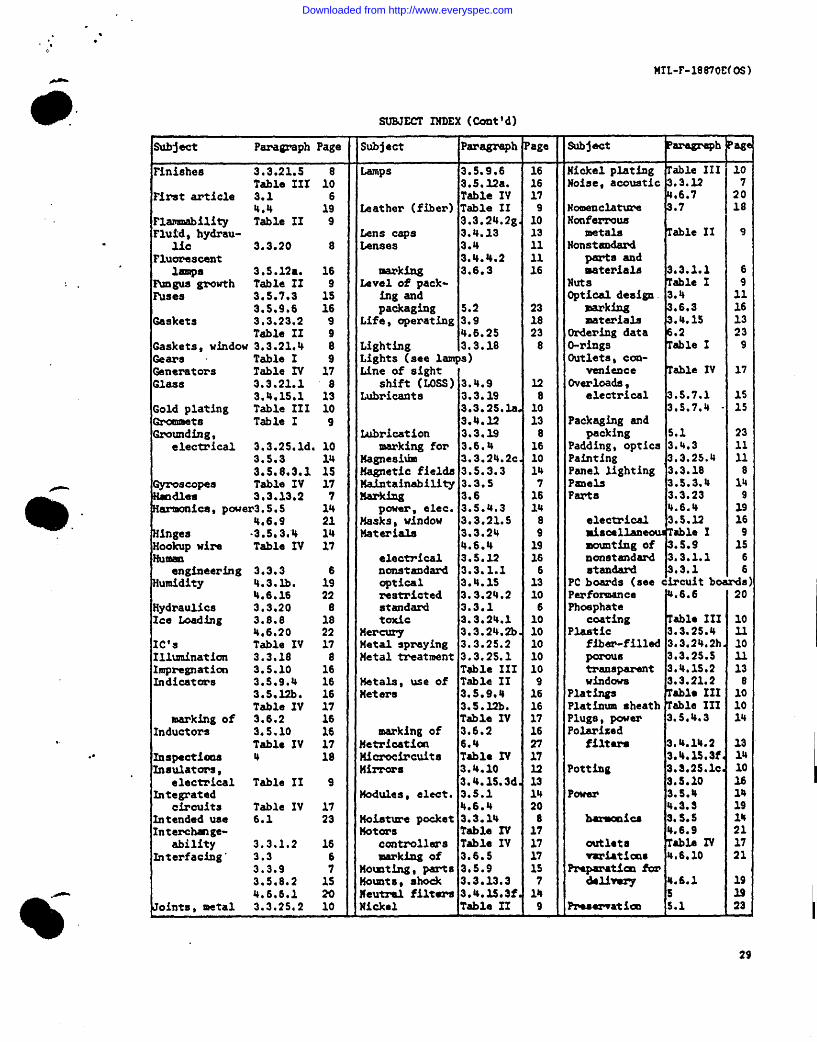
Downloaded from http://www.everyspec.com

“.
. .
. .
MIL-F-18870E(05 )●
SUBJECT INDEX(Cont'd)
subject
Pressure air 3.8.3 18 shields , 3.3.25.lb 10 Tuning devices4.3.lC. 19 3.5.3 Variable den-4.6.11 21 Table IV 14
sea water 3.8.4 18 shock, mechan- Varnish .3.25.54.6.10 22 ical- 3.8.5 18 Varnishing
Printedwiring 3.5.8.5 15 4.6.12 21 Verniers,3.5.9.2 15 shock mounts 3.3.13.3 7 marking of 3.6.2.3 16
PrOCedures , 3.3.25 10 shunts, aster Table XV 17 Vibration ● 8.6 18testing 4.6 29 silver costing 3,.4.10.3 32 .6.13 21
Procedures 3.3.25 10 plating Table 111 10 warmup .5.6 15Table III 10 S i z e 3.3.20 .6. S 20
Quality assur- 4.6.2 2 Water cooling .3.16.1 .84 18 Sockets Table IV 17 weight 3. 3.11 7
Solar radiation 3.8.10 l5 .6.3 19f onnsnce 4.5 19 4.6.24 23 Welding,
Radiation, elec- Soldering 3. 5.11.1 16 electricaltromagnetic 3.5.2 Solenoids Table IV 17 connect ions 3. 5.11.2 16
4.6.8 14 Springs table I 9 .structural .3.25.2 10solar 3.8.10 18 standard Hard- .3.25.6 11
4.6.24 23 ware Program 3.5.1 14 8Radioactive Standard p a r t s wind loading 3.8.9 18
mat erial 3 .3 .24 .2a . 10 and material 3.3.1 6 4.6.21 23Readouts (see indicators) Storage battery 3.5.4.2 14 windows .3.21 aReceptacles, Straps, ground 3.5.3.2 14 .4.15.1.1.13 13
power 3.5.4.3 14 stuffing tubes 3.5.8.1 15 Wipers, window 3.4.15.3e. 14Reflection S u n l i g h t ( s e e s o l a r r a d i a t i o nWire Tablee IV 17
reduction 3*4.13.3 13 switches 3.5.7.2 2.5 marking of 17Reflective Table IV 17
finishes15
3.3.25.3 10 symbols, mar- wood .3.24.2f. 10surfaces 3.4.10 12 king 3.6.1 16 WorKmanship” 18
3.4.15.3d. 13 synchros 3.5.8.4 15 Zinc die casting 3 .3.24.2d. 10Relays . Table IV 17 305.12c. 16 plating Table III 10Reliability 3.3.4 6 Temperature,Resilient mount 3.3.13.3 7 operating 3.8.1 18resistors Table IV 17 4.6.35 22Resolution, storage 3.8.2 18
photographic 3.4*7 12 4.6.14 21visual 3.4.6 11 testing “ 4.3. la. 19
Reticles 3.4.2 11 Terminal boards 3.5.9.2 153.4.l5.3b. 13 Table IV 17
Riveted joints 3.3.25.2 1 0 Terminals,Rotar, power grounding 3.5.3.1 14
Converters Table IV 17 Terminology,Safety 3.3.2 6 marking 3.6.1 16Salt atmosphere 3.8.7 18 Test conditions 4.3 19
4.6.17 22 ● quip-eat 3.3.8 7Samples 4.5,1 19 procdures 4.6 19scales Table I 9 Table V 20
marking of 3.6.2 16 Thermal design 3.3.16 8screws Table I 9 Threadedselection of fasteners Table I 9
documents 3.2 6 Time meters 3.5.Mh. 16Self-test pro Tin plating Table 111 10
Visions 3.3.9 7 Tools 3.3.7 7Semi conductors Table IV 17 Toxic materials 3.3.24.1 10Servicing 3.3.6 7 Transformers 3.5.10.1 16
4.6.4 20 3.5.10.2 16servo devices Table IV 17 Table XV 17Shafts 3.3.23.1 9 Transistors Table IV 17
Table I 9 Tubes, electron Table Iv 17
30
I
Downloaded from http://www.everyspec.com
Downloaded from http://www.everyspec.com

Downloaded from http://www.everyspec.com