specifications performance pump p/n n07 … manual.pdf · combustion smoke/bacharach scale..#1 or...
TRANSCRIPT

MODEL 5181BSPECIFICATIONS
06-06-05 Z08-02980 Supersedes 05-18-04 Z08-02980
MA
CH
INE
SP
EC
IFIC
AT
ION
S
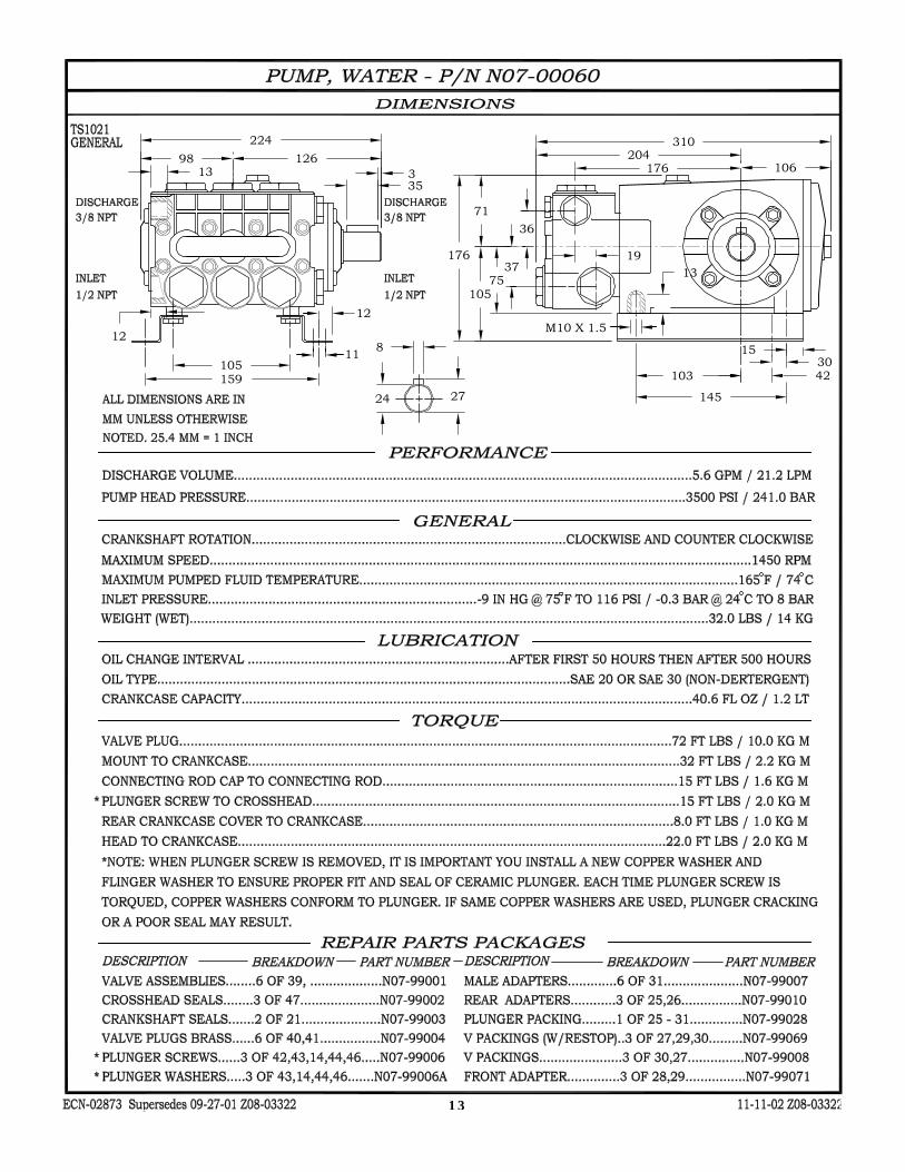
DISCHARGE VOLUME......................................4.8 GPM / 18.2LPM
PUMP HEAD PRESSURE................................ 1800 PSI / 124 BAR
TEMPERATURE RISE..........150°F @ 4.8 GPM / 65°C @ 18.2 LPM
TEMPERATURE LIMIT................................. UP TO 200 DEGREES
COMBUSTION SMOKE/BACHARACH SCALE..#1 OR #2 SMOKE
CARBON MONOXIDE ALLOWED.......................................... 0.01%
DRAFT/STACK INSTALLATION........... 0.2” - 0.04” WC READING
HEAT INPUT ........................ 490,000 BTU/HR / 123,480 KCAL/HR
MINIMUM INLET WATER PRESSURE................40 PSI / 0.68 BAR
STACK SIZE .............................................. 12” DIA / 304.8 MM DIA
WEIGHT (DRY) ................................................... 840 LBS / 366 KG
SPRAY TIP ........................................... (#7.5-15DEG) J00-15075-2
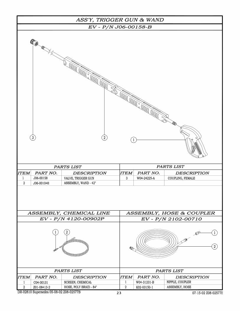
WAND 42” AND TRIGGER GUN ......................... P/N J06-00158-B
HOSE, HIGH PRESSURE .................. 3/8” X 50’ P/N K02-03150E1
STEAM NOZZLE (OPTIONAL) .............. (#35 ORF) P/N J05-00335
STEAM HOSE (OPTIONAL) .................................P/N K02-3150-1C
STEAM WAND (OPTIONAL) ............................... P/N 120-00700-B
BELT - MOTOR TO PUMP....................................... P/N R02-00236
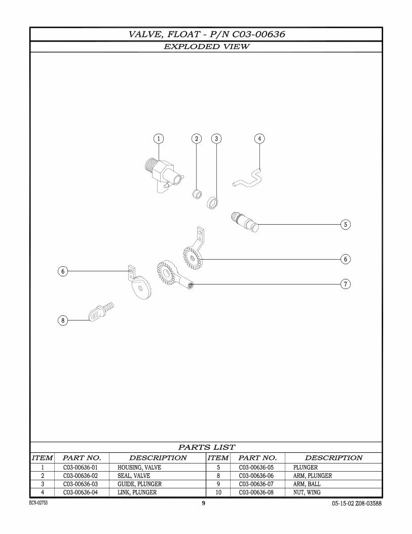
FLOAT VALVE........................................................ P/N C03-00636
COIL SIZE.....................30” O.D. X 1/2”ID X 189’ X SCHEDULE 80
REPLACEMENT COIL w/ WRAPPER..................... P/N 48-200-G3
COIL BACK PRESSURE (NEW)
..................5 PSI @ 4.8 GPM / 0.34 BAR @ 18.2 LPM
COIL BACK PRESSURE REQUIRING DESCALING
........................ 50 PSI @ 4.8 GPM / 3.40 @ 18.2 LPM
MACHINE VOLTAGE.............................................. 230V 60HZ 1PH
CAM SWITCH......................................................... P/N F04-00743A
TEMP CONTROL, ADJUSTABLE ........................... P/N F04-00818
CURRENT ............................................................................... 28 AMP
MOTOR HORSEPOWER........................................... 6 HP / 4.5 KW
MOTOR SPEED……………...............................................3450 RPM
MOTOR VOLTAGE......................................208V / 230V 60HZ 3PH
MOTOR PART NUMBER.......................................... P/N F02-00089
MOTOR PULLEY...................................................... P/N R03-00734
PUMP ........................................................................P/N N07-00060
PUMP PULLEY......................................................... P/N R03-00794
PUMP PULLEY BUSHING....................................... P/N R04-00001
PUMP TYPE..............GENERAL CERMAIC PLUNGER, OIL BATH
UNLOADER.............................................................. P/N C07-01501
NATURAL GAS - STANDING PILOT
FUEL TYPE................................................................ NATURAL GAS
MINIMUM FUEL INLET PRESSURE.................................... 7.5”W.C.
MAXIMUM FUEL INLET PRESSURE...................................... 9”W.C.
MAIN BURNER MANIFOLD PRESSURE............................ 3.5”W.C.
ORIFICE SIZE...................MAIN BURNER #50 DRILL - PILOT 0.020
VOLTAGE................................................................... 230V 60HZ 1PH
LIQUID PROPANE GAS - STANDING PILOT
FUEL TYPE................................................... LIQUID PROPANE GAS
MINIMUM FUEL INLET PRESSURE..................................... 10”W.C.
MAXIMUM FUEL INLET PRESSURE.................................... 14”W.C.
MAIN BURNER MANIFOLD PRESSURE..............................11”W.C.
ORIFICE SIZE...................MAIN BURNER #60 DRILL - PILOT 0.014
VOLTAGE................................................................... 115V 60HZ 1PH
N. G. - ELECTRONIC IGNITION (OPTION)
FUEL TYPE................................................................ NATURAL GAS
MINIMUM FUEL INLET PRESSURE.................................... 7.5”W.C.
MAXIMUM FUEL INLET PRESSURE...................................... 9”W.C.
MAIN BURNER MANIFOLD PRESSURE.............................3.5”W.C.
MAIN BURNER ORIFICE SIZE.......................................... #50 DRILL
FLAME SENSOR......................................................... P/N S03-00401
PILOT IGNITOR........................................................... P/N S03-00402
VOLTAGE..................................................................... 24V 60HZ 1PH
L. P. - ELECTRONIC IGNITION (OPTION)
FUEL TYPE................................................... LIQUID PROPANE GAS
MINIMUM FUEL INLET PRESSURE..................................... 10”W.C.
MAXIMUM FUEL INLET PRESSURE.................................... 14”W.C.
MAIN BURNER MANIFOLD PRESSURE..............................11”W.C.
MAIN BURNER ORIFICE SIZE.......................................... #60 DRILL
FLAME SENSOR........................................................ P/N S03-00401
PILOT IGNITOR........................................................... P/N S03-00402
VOLTAGE..................................................................... 24V 60HZ 1PH
ELECTRICAL
PERFORMANCE
GENERAL
PUMP & UNLOADER
PUMP MOTOR
BURNER

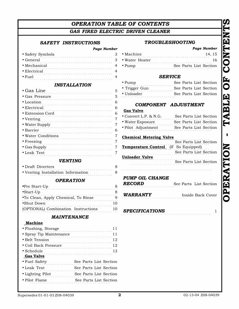
OPERATION TABLE OF CONTENTSGAS FIRED ELECTRIC DRIVEN CLEANER
02-13-04 Z08-04039Supersedes 01-01-03 Z08-04039 2
OPE
RA
TIO
N
- T
AB
LE
OF
CO
NT
EN
TS
SAFETY INSTRUCTIONSPage Number
• Safety Symbols 3• General 3• Mechanical 4• Electrical 4• Fuel 4
INSTALLATION• Gas Line 5• Gas Pressure 5• Location 6• Electrical 6• Extension Cord 6• Venting 7• Water Supply 7• Barrier 6• Water Conditions 7• Freezing 7• Gas Supply 7• Leak Test 7
VENTING• Draft Diverters 8• Venting Installation Information 8
OPERATION•Pre Start-Up 8•Start-Up 8•To Clean, Apply Chemical, To Rinse 9•Shut Down 10(OPTIONAL) Combination Instructions 10
MAINTENANCE Machine• Flushing, Storage 11• Spray Tip Maintenance 11• Belt Tension 12• Coil Back Pressure 12• Schedule 13 Gas Valve• Fuel Safety See Parts List Section
• Leak Test See Parts List Section
• Lighting Pilot See Parts List Section
• Pilot Flame See Parts List Section
TROUBLESHOOTINGPage Number
• Machine 14, 15• Water Heater 16• Pump See Parts List Section
SERVICE• Pump See Parts List Section• Trigger Gun See Parts List Section• Unloader See Parts List Section
COMPONENT ADJUSTMENT Gas Valve• Convert L.P. & N.G. See Parts List Section• Water Exposure See Parts List Section• Pilot Adjustment See Parts List Section
Chemical Metering ValveSee Parts List Section
Temperature Control (If So Equipped)See Parts List Section
Unloader ValveSee Parts List Section
PUMP OIL CHANGERECORD See Parts List Section
WARRANTY Inside Back Cover
SPECIFICATIONS 1

3
SAFETY, INSTALLATION, AND OPERATION
MACHINE UNPACKING ALL CLEANERS ARE CAREFULLY INSPECTED AND CARTONED TO PROTECT AGAINST SHIPPING DAMAGE. IF THERE IS DAMAGE OR MISSING PARTS, THE TRANSPORTATION COMPANY AGENT SHOULD MAKE A NOTATION TO THAT EFFECT ON THE BILL. REFER TO THE PARTS LIST IN THIS MANUAL AND ADVISE WHAT PARTS ARE MISSING OR DAMAGED. IF AVAILABLE, GIVE THE INVOICE NUMBER ON ALL ORDER BILLS. THIS PROCEDURE WILL ENABLE NEEDED PARTS TO BE SHIPPED QUICKLY.
THANK YOU for choosing our product. Please READ ALL Installation, Operation, and Maintenance instructions before operating the machine
NOTE: Refer to CLEANER MODEL for SERIAL NUMBER location
IMPORTANT SAFETY INSTRUCTIONS
The safety alert symbol is used to identify safety information about hazards that can result in personal injury. A signal word (DANGER, WARNING, or CAUTION) is used with the alert symbol to indicate the likelihood and the potential severity of injury. In addition, a hazard symbol may be used to represent the type of hazard
DANGER indicates a hazard which, if not avoided, will result in death or serious injury.
WARNING indicates a hazard which, if not avoided, could result in death or serious injury.
CAUTION indicates a hazard which, if not avoided, might result in minor or moderate injury. CAUTION, when used without the alert symbol, indicates a situation that could result in damage to the equipment.
ELECTRIC DRIVEN GAS FIRED CLEANERS
GENERAL SAFETY
1. Before operating this machine, read and observe all safety, unpacking, and operating instructions. Failure to comply with these instructions could create a hazardous situation.
2. The operator of this equipment should not operate this equipment when fatigued or under influence of alcohol or drugs.
3. The operator of this equipment should be thoroughly familiar with its operation and trained in the job to be accomplished.
4. The operator of this equipment should wear protective face shields and other protective clothing as required for safe operation.
5. Do not leave this machine unattended when it is operating.
6. All installations must conform to all applicable local codes. Contact your electrician, plumber, utility company or seller for details.
7. If a water leak is found, DO NOT OPERATE THE MACHINE. Shut off the motor and repair.
8. Follow instructions on how to stop the machine and bleed pressures quickly. Be thoroughly familiar with the controls.
9. Always point the gun assembly in a safe direction and do not direct spray on the cleaner.
10. Do not operate the machine if any mechanical failure is noted or suspected.
WARNING: RISK OF INJECTION OR SEVERE INJURY. KEEP CLEAR OF NOZZLE. DO NOT DIRECT DISCHARGE STREAM AT PERSONS. THIS EQUIPMENT IS TO BE USED ONLY BY TRAINED OPERATORS.
AVERTISSEMENT: R I S Q U E D’INJECTION ET DE BLESSURES
GRAVES. SE TENIR À L’ÉCART DU JET. NE PAS DIRIGER LE JET DE SOTIE VERS D ’AUTRES PERSONNES CONF IER L’UTILISATION LE JET DE SOTIE VERS D ’AUTRES PERSONNES. CONFIER L’UTILISATION DE CE MATÉRIEL À UN OPÉRATEUR QUALIFIÉ.
10-00 Z08-02860 ECN-02375

4
11. Do not start the machine unless the gun assembly is firmly gripped by the machine operator. Failure to do this could result in injury from a flying hose and gun assembly.
12. When starting a job, survey the area for possible hazards and correct before proceeding.
13. If chemicals are used in conjunction with this equipment, read and follow the product label directions.
14. During normal operation of this machine, hot discharges and surfaces may be produced. Avoid burns by being aware of these areas and staying clear of them during and immediately after equipment operation.
15. Do not start the burner unless a full flow of water is coming from the gun. Air leaks, insufficient water to the machine, or an open soap valve with no chemical means less than full flow through the coil. This could cause hose failure and burns to the operator.
WARNING: OPEN FLAME: Do not operate this machine in an area with combustible materials. A suitable fire extinguisher should be available in operating area.
MECHANICAL SAFETY 1. All guards, shields, and covers must be
replaced after adjustments are made. This will prevent accidental contact with any hazardous parts.
2. Drive belts must be inspected and tightened periodically to operate at optimum levels
3. Inspect machine for damaged or worn components and repair or replace to avoid potential hazards. Do not operate the machine if any mechanical failure is noted or suspected.
4. Always use the correct size spray tip found in the GENERAL section of the MODEL SPECIFICATIONS or MODEL EXPLODED VIEW.
ELECTRICAL SAFETY 1. This machine must be electrically grounded.
Failure to have the machine grounded may result in the operator being electrically shocked and even death.
2. Do not plug-in or un-plug machine with wet hands.
3. Keep power cords and connections (connectors) out of water.
4. If an extension cord must be used to operate this machine, it should be as short as possible. The extension cord must be properly sized and fitted with a grounding type plug and receptacle.
5. All wiring and electrical connections should comply with the National Electrical Code (NEC) and with local codes and practices.
6. Fuses or circuit breakers should be compatible with machine requirements. (See ELECTRICAL section of MODEL SPECIFICATIONS for power requirements.)
7. High voltage may be present within this machine. Servicing should only be performed by properly trained personnel.
FUEL SAFETY
DANGER: To avoid possible injury, fire, or explosion, please read and follow these instructions. N.G. (Natural) gas is lighter than air and will generally rise through the venting and escape harmlessly.
L.P. (Propane) gas is heavier than air and like water, will flow to the lowest level. Before lighting the pilot burner, sniff at the lowest level. If you smell gas, follow these rules:
1. Get all the people out of the building.
2. DO NOT light matches. DO NOT turn electric switches or light switches on or off in the area. DO NOT use an electric fan to remove gas from the area.
3. Shut off the gas supply from the outside of the building.
4. Telephone (from another location) Gas Company and Fire Departments. Ask instructions. DO NOT go back into the building.
5. Use only fuel for the water heater burner specified in the BURNER section of MODEL SPECIFICATIONS. The use of incorrect fuel may result in fire or explosion and severe injury to the operator.
6. Fuel burning equipment must have proper ventilation for cooling, combustion air, and exhausting of combustion products.
7. Stacking, where required, must be installed in accordance with all local codes. A draft
10-00 Z08-02860A ECN-02375
5
diverter must be installed on a machine connected to an exhaust stack to prevent improper operation. (See GENERAL section of MODEL SPECIFICATIONS for stack size).
8. Where stacking is not required, provide adequate ventilations to prevent any possible accumulation of hazardous fumes.
9. Personnel trained in and familiar with the type of equipment being serviced should only perform adjustments to fuel burning equipment.
SAVE THESE SAFETY
INSTRUCTIONS
INSTALLATION
There are four main things to consider when installing your machine.
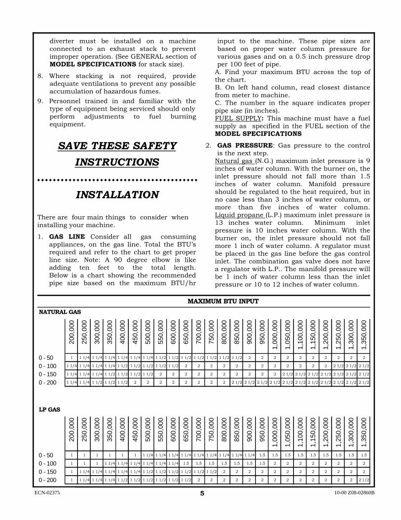
1. GAS LINE Consider all gas consuming appliances, on the gas line. Total the BTU’s required and refer to the chart to get proper line size. Note: A 90 degree elbow is like adding ten feet to the total length. Below is a chart showing the recommended pipe size based on the maximum BTU/hr
input to the machine. These pipe sizes are based on proper water column pressure for various gases and on a 0.5 inch pressure drop per 100 feet of pipe.
A. Find your maximum BTU across the top of the chart. B. On left hand column, read closest distance from meter to machine. C. The number in the square indicates proper pipe size (in inches). FUEL SUPPLY: This machine must have a fuel supply as specified in the FUEL section of the MODEL SPECIFICATIONS
2. GAS PRESSURE: Gas pressure to the control is the next step.
Natural gas (N.G.) maximum inlet pressure is 9 inches of water column. With the burner on, the inlet pressure should not fall more than 1.5 inches of water column. Manifold pressure should be regulated to the heat required, but in no case less than 3 inches of water column, or more than five inches of water column. Liquid propane (L.P.) maximum inlet pressure is 13 inches water column. Minimum inlet pressure is 10 inches water column. With the burner on, the inlet pressure should not fall more 1 inch of water column. A regulator must be placed in the gas line before the gas control inlet. The combination gas valve does not have a regulator with L.P.. The manifold pressure will be 1 inch of water column less than the inlet pressure or 10 to 12 inches of water column.
ECN-02375
200,
000
250,
000
300,
000
350,
000
400,
000
450,
000
500,
000
550,
000
600,
000
650,
000
700,
000
750,
000
800,
000
850,
000
900,
000
950,
000
1,00
0,00
0
1,05
0,00
0
1,10
0,00
0
1,15
0,00
0
1,20
0,00
0
1,25
0,00
0
1,30
0,00
0
1,35
0,00
00 - 50 1 1 1/4 1 1/4 1 1/4 1 1/4 1 1/4 1 1/4 1 1/2 1 1/2 1 1/2 1 1/2 1 1/2 1 1/2 1 1/2 2 2 2 2 2 2 2 2 2 2
0 - 100 1 1/4 1 1/4 1 1/4 1 1/4 1 1/2 1 1/2 1 1/2 1 1/2 1 1/2 2 2 2 2 2 2 2 2 2 2 2 2 2 1/2 2 1/2 2 1/2
0 - 150 1 1/4 1 1/4 1 1/4 1 1/2 1 1/2 1 1/2 1 1/2 2 2 2 2 2 2 2 2 2 2 2 1/2 2 1/2 2 1/2 2 1/2 2 1/2 2 1/2 2 1/2
0 - 200 1 1/4 1 1/4 1 1/2 1 1/2 1 1/2 2 2 2 2 2 2 2 2 2 1/2 2 1/2 2 1/2 2 1/2 2 1/2 2 1/2 2 1/2 2 1/2 2 1/2 2 1/2 2 1/2
200,
000
250,
000
300,
000
350,
000
400,
000
450,
000
500,
000
550,
000
600,
000
650,
000
700,
000
750,
000
800,
000
850,
000
900,
000
950,
000
1,00
0,00
0
1,05
0,00
0
1,10
0,00
0
1,15
0,00
0
1,20
0,00
0
1,25
0,00
0
1,30
0,00
0
1,35
0,00
0
0 - 50 1 1 1 1 1 1 1 1/4 1 1/4 1 1/4 1 1/4 1 1/4 1 1/4 1 1/4 1 1/4 1 1/4 1.5 1.5 1.5 1.5 1.5 1.5 1.5 1.5 1.5
0 - 100 1 1 1 1 1/4 1 1/4 1 1/4 1 1/4 1 1/4 1 1/4 1.5 1.5 1.5 1.5 1.5 1.5 1.5 2 2 2 2 2 2 2 2
0 - 150 1 1 1/4 1 1/4 1 1/4 1 1/4 1 1/4 1 1/2 1 1/2 1 1/2 1 1/2 1 1/2 1 1/2 2 2 2 2 2 2 2 2 2 2 2 2
0 - 200 1 1 1/4 1 1/4 1 1/4 1 1/2 1 1/2 1 1/2 1 1/2 1 1/2 1 1/2 2 2 2 2 2 2 2 2 2 2 2 2 2 2 1/2
LP GAS
MAXIMUM BTU INPUT
NATURAL GAS
10-00 Z08-02860B

6
This machine emits carbon monoxide, a deadly gas, and must be vented if used in an enclosed area. Improper venting can cause poor combustion, delayed ignition, down drafts, and the possibility of freezing the coil. Contact your distributor or local heating and air conditioning dealer for proper materials. Local codes must be observed.
3. VENTILATION: The gas fired machine must be vented. See the VENTING section of this manual.
4. WATER SUPPLY: This machine must have a water supply meeting or exceeding the maximum discharge volume specified in the PERFORMANCE section, and a minimum water inlet pressure specified in the GENERAL section of the MODEL SPECIFICATIONS.
OTHER ITEMS TO CONSIDER BEFORE
INSTALLATION
1. LOCATION: This machine should be installed by only qualified technicians. The machine should be set upon a level surface where it will not be affected by strong winds, rain, snow, extreme heat, and freezing temperatures. Install the machine considering locations for chemical pick-up, fuel connections, electrical connections, water hook-up, venting, and maintenance. All wiring and electrical connections should comply with the National Electrical Code (NEC) and with local codes and practices. Use the chart under item 4 for your cord selection.
2. GAS AND ELECTRICITY: Gas and electricity must be shut off when installing or servicing.
3. LOCAL CODES: Installation and servicing must only be performed by qualified personnel and must conform to local codes and ordinances and with National Fuel Gas Code (ANSI Z223.1 and NFPA No. 54).
5. FIRE HAZARD: Keep combustible materials away from gas machines. DO NOT allow lint or dust to collect in the burner area.
WARNING
CARBON MONOXIDE HAZARD
6. .QUALIFIED PERSONNEL: All installation and servicing must only be performed by qualified personnel and must conform to the local codes and with the Natural Gas Code ANSI Z223.1/NFPA No. 54.
7. BARRIER: We recommend that a barrier be installed between the machine and wash area to prevent spray from the wand from coming in direct contact with electrical controls, motors and transformers. This will increase the machine’s life and lessen electrical problems.
8. CHEMICALS: Mix chemicals per the chemical manufacturers printed directions. Follow all mixing, handling, application, and disposal instructions. Wear gloves, boots, goggles, and protective clothing appropriate for the chemical being used.
ELECTRICAL INSTALLATION
1. ELECTRICAL: Connect the machine to an electrically grounded circuit that is fused or circuit breaker protected. The circuit must match that specified in the ELECTRICAL section under MODEL SPECIFICATIONS.
2. EXTENSION CORD: The use of an extension cord that has undersize wire compared to the amp draw of your machine will adversely limit the starting load carrying abilities of the motor and machines performance. Use only 3-wire extension cords that have 3-prong plugs and 3-pole cord connectors that accept the plug from the product. Use only extension cords that are intended for outdoor use. These extension cords are identified by a marking “Acceptable for use with outdoor appliances; store indoors while not in use.” Use only extension cords having an electrical rating not less than the rating of the product. Do not use damaged extension cords. Use an extension cord in good repair free of frays or cracks in the outer covering. Do not abuse extension cord and do not yank on any cord to disconnect. Keep cord away from heat and sharp edges. Always disconnect the extension cord from the receptacle before disconnecting the product from the extension cord.
09-00 Z08-02860C ECN-02375
WARNING
ELECTRICAL SHOCK HAZARD

7
6. L.P. FIRED MACHINES: This machine should be installed with consideration to cold weather. As weather gets colder, the rate of liquid being vaporized into gas in the fuel storage tank will decrease. The storage tank(s) must be sized sufficiently large enough to ensure an adequate supply of vaporized fuel at all anticipated outdoor temperatures. Your L.P. supplier can recommend the correct tank(s) knowing the piping layout and the BTU demand found the in MODEL SPECIFICATIONS.
7. FUEL OUTAGE: If your L.P. tank runs out of fuel or if the natural gas supply is interrupted, turn off the gas at the machine. After L.P. tank is filled, or the natural gas is restored, relight pilot burner per LIGHTING PILOT BURNER instructions.
WATER INSTALLATION
1. WATER TEMPERATURE VARIATION: On machines not equipped with a temperature control device, the temperature of the discharged water is dependant on the incoming water temperature. Some minor adjustment to the fuel input may be required if the incoming water is significantly different than 50 degrees fahrenheit.
2. WATER CONDITIONS: Local water conditions affect the coil and spray tip more adversely than any other element. In areas where troublesome conditions may exist with like equipment (such as water heaters), we recommend the use of a water softener.
3. FREEZING: This machine must be protected from freezing according to STORAGE section of MACHINE MAINTENANCE.
4. WATER EXPOSURE: If your gas control valve has been exposed to water in any way, do not attempt to use it. It must be replaced. Do not attempt to repair the gas control valve.
VENTING WARNING: This machine emits carbon
monoxide, a deadly gas, and must be vented if used in an enclosed area. Improper venting can cause poor combustion, delayed ignition, down drafts, and the possibility of freezing the coil. Contact your distributor or local heating and air conditioning dealer for proper materials. Local codes must be observed.
09-00 Z08-02860D ECN-02751
WARNING: To reduce risk of electrocution,
keep all connections dry and off the ground. Do not touch plug with wet hands.
CHART FIGURES ARE BASED ON NOT MORE THAN 100 FOOT
(Based on Ambient Temperature of 86°F (30°C)). *Use Amp Draw indicated the same or higher than your machine output EXAMPLE: Machine Amp Draw 51, use 55 (2 Conductor). The thermostat type of cord shall be C, PD, E, EO, EN, S, SO, SRD, SJ, SJO, SV, SVO, SP. The thermoset plastic types shall be ET, ETT, ETLB, ETP, ST, STO, SRDT, SJT, SJTO, SVT, SVTO, and SPT.B
FUEL INSTALLATION
1. N.G. AND L.P.: Caution must be taken to ensure that no raw gas is present in the surrounding area before attempting to put the machine into operation, or when relighting the pilot burner.
2. GAS SUPPLY: Do not connect the machine to supply piping before testing gas supply pressure. Excessive pressure may cause damage to gas control valve.
3. LEAK TEST: All the gas connections should be tested for leaks per the LEAK TEST instructions found in the GAS VALVE SERVICING..
4. CONVERTING N.G. to L.P.: The regulator and vent tube must be removed, a plate installed on the gas valve, and main burner and pilot burner jets changed.
5. CONVERTING L.P. to N.G.: A regulator must be installed on the gas valve, a vent tube added, and main burner and pilot burner jets changed.
COPPER WIRE SIZE MINIMUM
AWG
MACHINE AMP DRAW*
3 CONDUCTOR WIRES
2 CONDUCTOR WIRES
16 15 14 12 10 8 6 4 2
10 -- 15 20 25 35 45 60 80
13 -- 18 25 30 40 55 70 95

8
horizontal stacks are used, vertical stacking must extend at least two feet for every foot of horizontal stack.
3. Stack Extension above the roofline should be sufficient to clear the peak of the roof. Refer to the ANSI Z223.1.
4. A Rain Cap that is U.L. approved should be installed on the stack.
OPERATING INSTRUCTIONS
PRE START-UP
1. The first time the machine is operated, after repairs have been made, or if the machine has set for a period of time (30 days or more) follow the following procedures.
A. Check the tension of the belt (if so equipped) per instructions in MACHINE MAINTENANCE.
B. Flush the machine per instructions in MACHINE MAINTENANCE.
C. Install float tank drain plug (if so equipped).
D. Open float tank ball valve (if so equipped).
♦ CAUTION: Always use the factory supplied pressure wash hose with your machine. Do not substitute other hoses as a potential safety problem may develop.
♦ CAUTION: If machine has been exposed to sub-freezing temperatures, it must be thoroughly warmed to above freezing before operating. Failure to warm machine can cause damage to the pump packings and other components.
2. Read and observe all items in “CLEANER INSTALLATION”.
The information contained herein is offered for reference only. You must comply with local codes and investigate through your gas and other utility companies when installing, as there may be some special local requirements you must comply with. Also see ANSI Z223.1 GAS FIRED MACHINES operate on the “Natural Draft” principle that rising heat creates an air lift. To eliminate a draft through the combustion chamber and cause pilot outages, a bell type draft diverter must be used. OIL FIRED MACHINES use a forced air burner. The oil burner can be influenced by “Natural Draft” even though they have their fan. A bell type draft diverter must be used here also.
OIL OR GAS FIRED MACHINES ARE NOT TO BE CONNECTED TO A TYPE B GAS VENT.
NE PAS RACCORDER CET APPAREIL À UN TUYAU D’ÉVACUATION DE GAZ DU TYPE B.
DRAFT DIVERTERS:
1. A draft diverter must be used on all cleaners that are stacked. This includes any chimney even if not expelled to the outside.
2. Use a draft diverter of the inverted funnel or bell type that meets all codes for capacity and materials. Mount the draft diverter directly to the stacking flange on the machine.
3. The draft diverter’s function is to insure that the barometric pressures are as close to the same as possible at the air inlet and outlet to the coil and will not be changed by either up drafts or down drafts.
4. Installation of a draft diverter WILL NOT PREVENT THE COIL FROM FREEZING. In areas where freezing temperatures are common, some type of down draft prevention must be used. Check local codes for acceptable methods for the prevention of down drafts.
VENTING INSTALLATION
INFORMATION:
1. Never Reduce the Stack size. The diverter and stacking should be the same size as the stack opening on the machine.
2. Straight Stacking through the a roof is preferred. Horizontal runs are not desirable, but if necessary, be sure to pitch the stack upward at a rate of two inches per foot. When
10-00 Z08-02860E ECN-02375
VENT / RAIN CAP
DIVERTER
9
♦ BALL VALVE: Check the position of the ball valve (if so equipped) on outlet line of the float tank assuring that it is in the open po-sition.
1. Light the pilot per LIGHTING PILOT in GAS VALVE SERVICE.
2. Select temperature (if so equipped).
3. With the gun assembly in hand (on trigger gun models hold the trigger gun valve in open position) and with a good flow of water turn on the pump switch.
CAUTION: A good flow of water must be flowing from the end of a gun within 30 seconds, before proceeding. Lack of water can cause damage to the water pump. CAUTION: On a machine equipped with a trigger gun valve, if the trigger gun valve remains in the closed position for more than 3 minutes, water pump damage may occur.
4. Turn the switch to the burner position. NOTE: .The .burner will Ignite within 5 to 30 seconds.
CAUTION: OIL FIRED MACHINE Do not run the machine with the burner switch in the on position when the fuel tank is empty. This will cause damage to the fuel pump and void warranty. CAUTION: Do not operate with the trigger gun valve closed for more than 3 minutes or water pump damage may occur.
5. To CLEAN:
A. Start on the lower portion of the area to be cleaned and work up using long, even, overlapping strokes.
B. Dirt is generally removed easily if grease and/or oil is not present. However if grease and/or oil are present, hot water and chemical will accelerate in the cleaning process.
CLOSEDOPEN
START-UP
♦ Refer to the MAINTENANCE SCHEDULE for
any maintenance to be performed before operation.
♦ ELECTRICAL: Connect the machine to an electrically grounded circuit that is fused or circuit breaker protected. Do not use any type of adapter. If the correct type of receptacle is not available, have one installed by a qualified electrician.
♦ OIL LEVEL: Check the oil level in the water pump, the gear case (if so equipped), and the engine.
♦ BELT (if so equipped): Make sure the belt tension and condition is as specified in MACHINE MAINTENANCE.
♦ METERING VALVE (if so equipped): Make sure the metering valve is closed before operation. If air enters the system through this valve, poor performance and machine damage will occur. Refer to the metering valve insert for proper operation.
♦ FUEL FILTER: Inspect the fuel filter for any evidence of water contaminants.
♦ FUEL: Make sure the fuel is the type specified in the BURNER section of MODEL SPECIFICATIONS
♦ FUEL QUANTITY: Make sure the fuel supply is sufficient to complete the job. See the G E N E R A L s e c t i o n o f M O D E L SPECIFICATIONS for the fuel tank capacity.
♦ WATER SUPPLY: This machine must have a water supply meeting or exceeding the maximum discharge volume specified in the PERFORMANCE section, and a minimum water inlet pressure specified in GENERAL section of the MODEL SPECIFICATIONS.
♦ LIME: Water containing large amounts of lime, calcium or other similar materials can produce a coating on the inside of the impact nozzle or spray tip and coil pipe.
♦ FLOAT TANK: Check the float tank to assure it is full and the float tank valve shuts off securely.
10-00 Z08-02860F ECN-02375
WARNING
ELECTRICAL SHOCK HAZARD

10
COMBINATION OPTION
INSTRUCTIONS WARNING: This machine should be
operated only by personnel instructed in and familiar with its operation. The discharge produced is 300°F / 150°C and can cause SERIOUS BODILY INJURY to you and anyone coming in contact with it.
NOTE: In process of making steam, the water flow through the coil has to be decreased. The amount of water is determined by the pressure and water temperature of your location.
If the incoming water temperature is as high as 70°F, the amount of water going through the coil has to decrease very little.
If the incoming water temperature is as low as 40°F, the amount of water going through the coil has to be decreased quite a bit.
The water temperature is relative to the season variation and should be taken in consideration when operating steam.
1. Install the open gun assembly.
2. Open the ball valve on coil inlet assembly.
3. Set the temperature control to 300°F MAXIMUM.
4. For startup see “START UP” section on the previous page.
5. Regulate the temperature indicated on the thermometer to 300°F by turning the regulating valve on the coil inlet assembly clockwise to DECREASE the temperature and counter clockwise to INCREASE the temperature.
6. For shut down follow “SHUT DOWN” previously shown on this page.
7. Close the ball valve on the coil inlet assembly.
6. TO APPLY CHEMICAL:
CHEMICAL: Use factory recommended chemicals for best cleaning action and for extended pump life. Contact your dealer for chemicals available. Follow instructions on chemical container.
Mix chemicals per label instructions. Use necessary safety precautions.
A. Insert chemical screen into chemical container
B. Adjust metering valve (if so equipped).
C. If the gun assembly is equipped with variable or multiple nozzle assembly, adjust as desired.
7. To RINSE: (For cold water rinse, turn the burner switch off.)
A. If the machine is equipped with a panel mounted metering valve, close the chemical metering valve. NOTE: It is advisable to dip the chemical screen in a container of clean water and open the valve 1 minute to clean the valve of any remaining residue.
B. If the gun and wand is equipped with variable or multiple nozzle assembly, open and close to clean nozzle of any remaining residue.
C. After a clear flow of water is noted from the end of the wand, start from the top, working downward using long, overlapping strokes.
SHUT-DOWN
1. Turn the burner switch off. (If not already
done so in the cold water rinse.)
2. After cool, clear water is coming from the end of the wand, turn the pump switch to off.
3. Turn off the water supply.
4. Disconnect from the electrical supply.
5. Replace the stack cover (if so equipped)
6. If freezing conditions may exist, refer to STORAGE in MACHINE MAINTENANCE.
7. Replace stack cover (if so equipped).
10-00 Z08-0286OG ECN-02375
OPEN CLOSED
TEMPERATUREINCREASE
TEMPERATURE
PRESSURE REGULATING
VALVE
DECREASE
FIGURE 1 FIGURE 2

MACHINE MAINTENANCE
FLUSHING 1. Connect machine to an electrically grounded
circuit that is fuse or circuit breaker protected.
2. Connect machine to a pressurized water supply meeting the requirements specified in the GENERAL section of the MODEL SPECIFICATIONS.
3. Turn on the water supply.
4. Check the float tank (if so equipped) to assure it is full and the float valve shuts off securely.
5. Check the position of the ball valve (if so equipped) on outlet line of the float tank assuring it is in the open position.
6. Remove spray tip from gun assembly.
7. With gun assembly in hand, turn on the pump switch. On trigger gun models hold the trigger gun valve in open position. CAUTION: DO NOT RUN PUMP WITHOUT WATER, AS THIS WILL CAUSE DAMAGE TO THE PUMP AND VOID WARRANTY.
8. When clean water flows from gun, turn off the switch.
9. Reinstall spray tip.
10. With gun assembly in hand, turn on the switch. On trigger gun models hold the trigger gun valve in open position.
11. When clean water flows from gun, turn off the pump switch.
12. If freezing conditions may exist, refer to “STORAGE” section.
13. Turn off and disconnect the water supply.
15. Disconnect electrical supply.
STORAGE 1. Rinse the Soap Line by inserting the screen
into a container of clear water and open the metering valve 1 minute to clean it of any remaining residue. Be sure the chemical metering valve is closed when finished.
2. Disconnect the water supply.
ELECTRIC DRIVEN GAS FIRED CLEANERS
3. Remove the spray tip nozzle from gun assembly and wire to machine.
4. Check the position of the ball valve (if so equipped) on the outlet of the float tank assuring it is in the closed position.
5. Attach an air chuck to the air valve stem on the pump assembly. With the trigger gun in the open position, apply air until a mixture of air and very little water is coming from the gun wand Then turn switch to the burner position and depress the vacuum switch. Run it for 45 seconds allowing any remaining water to turn to steam.
6. Fill a 1-gallon container with Ethylene Glycol type antifreeze. Minimum should be a mixture of ½ antifreeze and ½ water strength before each use, as the antifreeze will dilute with each use.
7. Install a 2-ft. Garden hose to the water inlet. Insert the other end into a container of antifreeze solution.
8. With the discharge gun assembly in hand, turn on the switch. On trigger gun models hold the trigger gun valve in open position.
9. Turn off the switch just prior to running out of antifreeze mixture.
10. Disconnect electrical supply.
11. Disconnect gun and hose.
12. Place machine in a dry place protected from weather conditions.
SPRAY TIP MAINTENANCE 1. Remove the spray tip from the gun assembly.
2. Blow out debris with compressed air from the outside in. Any debris remaining in the inlet side of the nozzle should be cleaned out. If lime or chemical scale is present in the inlet side, the nozzle may be soaked in descaling solution or replaced. If the tip is worn, replace with one specified in the GENERAL section of MODEL SPECIFICATIONS or MODEL EXPLODED VIEW.
3. Before replacing spray tip flush the machine per “FLUSHING”.
4. Reinstall Spray tip to gun assembly.
10-00 Z08-02861 ECN-02311 11

MACHINE MAINTENANCE CONT’D
BELT TENSION DEFLECTION
SPAN
1. Correct belt tension will allow a 1/64-inch deflection for each inch of span between pulley centers with a 6-pound force applied i n t h e m i d d l e o f t h e s p a n . EXAMPLE: A 6-pound force applied at the middle of an 8 inch span should produce a deflection of 8/64 inch or 1/8 inch.
2. Belts can be tightened or loosened by loosening the nuts holding the pump assembly to the motor mount. Then tighten or loosen the j-bolt on the motor mount. Retighten the pump assembly after the desired tension is reached.
COIL BACK PRESSURE CHECK
Above is a cross section view showing the progressive liming of coils.
A regular maintenance schedule for descaling your heating coil is essential to insure its longevity.
The frequency of descaling depends upon the amount of use and the condition of the water.
COIL BACK PRESSURE CHECK INSTRUCTIONS
1. Check the condition of your water pump unloader valve. Remove the hose and gun assembly from the coil outlet.
ELECTRIC DRIVEN GAS FIRED CLEANERS
2. Remove any flow restrictions, such as guns and hoses, from the coil outlet.
3. Install a pressure gauge between the water pump and coil inlet.
DISCHARGE VOLUME BACK PRESSURE
GPM REQUIRING DESCALING
2-3 GPM 50 PSI
3-4 GPM 75 PSI
4-5 GPM 100 PSI
6 GPM 150 PSI
8-10 GPM 175 PSI
USE A 1000 PSI PRESSURE GAUGE
3. Turn on the water supply. Check the float valve (if so equipped) to assure float tank is full and the float valve shuts off securely.
4. Check the position of the ball valve (if so equipped) on the outlet line of the float tank assuring it is in the open position.
5. Turn on the pump switch. If the coil back pressure reading is above that found in the GENERAL section of the MODEL SPECIFICATIONS then your machine needs to be descaled.
A separate descaling pump is recommended so scale and other chemicals will not come in contact with your water pump and causes premature wear.
NOTE: Contact your local dealer for descaling of your unit.
7. Disconnect the water supply.
8. Disconnect the electrical supply.
9. Reinstall the hose and gun assembly.
10. Remove the pressure gauge.
ACCESSORIES PART NO. DESCRIPTION
Y02-00001 ……..… 0-1000 PSI (69 BAR) Pressure Gauge
Z01-00070-1…….…3/8” x 100 Yards Thread Tape
NOTE: All Gauges are Glycerin Filled ¼ NPT
02-16-01 Z08-02861A ECN-02407 Supercedes 10-00 Z08-02861A 12

DAILY EACH HR FIRST 8
HRS
AFTER FIRST 50
HRS
EVERY 50 HRS
EVERY 100 HRS
EVERY 500 HRS YEARLY
MACHINE MAINTENANCE
1. OIL BATH WATER PUMP:
Oil Level – check and add as needed per PUMP SERVICE insert.
Oil Change – drain and refill per PUMP SERVICE insert. CAUTION: Used oil must be disposed into an environment safe container and brought to an oil re-cycling center.
Oil Contamination – Milky color indi-cates water
2. HOSES:
Blistering, Loose Covering.
Abrasion of cover exposing reinforce-ment.
Cuts exposing reinforcement.
3. BELTS:
Cracks or fraying
For correct belt tension, see MACHINE MAINTENANCE insert.
4. FILTER – WATER:
Check water inlet hose screen for debris
Check float tank screen for debris
5. SPRAY TIP:
Check Tip for debris.
6. FUEL:
Adequate fuel supply.
7. PUMP MOTOR WITH GREASE
FITTINGS:
Remove drain plug. Use 1 or 2 full strokes of Shell “DOLIUM R”, Chevron “SR1 No. 2” or Texaco “PREMIUM RB”. Operate for 20 minutes and replace drain plug.
8. GUARDS AND SHIELDS:
Check that all guards and shields are in place and secure.
9. FREEZING TEMPERATURES:
Freezing temperatures break coils and water pumps. See STORAGE in the MACHINE MAINTENANCE section for cold weather instructions.
ELECTRIC DRIVEN GAS FIRED CLEANERS
10-00 Z08-02862 ECN-02375 13

TROUBLE POSSIBLE CAUSE REMEDY
1. Poor Cleaning Action.
A. Hard water.B. Low Pressure.C. Little or no chemical being drawn.D. Improper chemical.E. Improper chemical mixture.
F. Low Discharge Pressure.
A. Connect machine to water softener.B. See "Low operating pressure"C. See "Machine will not draw chemical".
D. Obtain proper chemical.E. Mix chemicals per the label. Follow allmixing, handling, application, and disposalinstructions.F. See "Low operating pressure"
2. Machine will not draw chemical.
A. No chemical solution.B. Metering valve not open.C. Chemical line strainer clogged.Air leak in chemical line.D. Metering valve clogged.
E. Restrictor orifice too large or missing.
A. Replenish supply.B. Turn metering valve knob to open.C. Remove screen and clean.
D. Tighten all fittings and hoses for the chemical line.E. Disassemble and clean. Install proper size orifice.
3. Low operating pressure
A. Insufficient water supply.
B. Incoming water hose too small.C. Water supply hose too long.D. Belt slippage.
E. Worn Belt.
F. Spray tip worn or wrong size.
G. Dirty or worn check valves in water pump.H. Water supply hose kinked.I. Inlet filter screen clogged.
J. Motor runs slow.
K. Air leak in inlet plumbing.L. Defective water pump.M. Leaking discharge hose.
N. Chemical metering valve open and sucking air.O. Defective unloader valve.P. Inlet ball valve not fully open (if so equipped)
A. The water supply must meet or exceed the maximum discharge volume specified in the PERFORMANCE section, and minimum water inlet pressure specified in the GENERAL section of the MODEL SPECIFCATIONS section.B. Use larger water supply hose.C. Use shorter water supply hose.D. Tighten belt per instructions in MACHINE MAINTENANCE insert.E. Replace belt per CLEANER EXPLODED VIEW.F. Replace with spray tip specified in the GENERAL section of MODEL SPECIFICATIONS.G. See PUMP TROUBLESHOOTING.
H. Straighten hose.I. Clean water filter screen or hose inlet screen.J. See "Pump engine starts slow or overheats and stops".K. Tighten all fittings.L. See PUMP TROUBLESHOOTING.M. If a water leak is found, DO NOT OPERATE THE MACHINE. Disconnect the power and replace hose.N. Resupply chemical, place soap screen in water, or shut off metering valve.O. Repair or replace unloader valve.P. Open inlet ball valve completely. (Handle parallel w/valve body).
ELECTRIC MOTOR DRIVEN PRESSURE CLEANERS
CLEANER TROUBLESHOOTING
ECN -02981 Supersedes 06-00 Z08-02850 07-15-03 Z08-0285014

TROUBLE POSS IBLE CAUSE REM EDY
4. Excessive , unusual noise .
A . Defective Pump.B. Defective motor.
C. Pulleys rubbing.D . Misalignment of pump & motor
A. See P U M P TROUBLESHOOTING .B .Call service technician or take engine to Repair/Warran ty station .C . Adjust sh ields or pulley (s).D . Real ign pump and engine.
5. .Be lts slipping. A . Belts too loose.
B. Excessive Back Pressure.C. Defective Water Pump.
A. Tigh ten belt per instructions on M ACHINE M AINTENANCE .B . See "Excessive Back Pressure" below.C . See P U M P SERVICE .
6. Excessive Back Pressure
A. Spray tip built up with lime .
B. Water pump turning too fast.C. Coil built up with lime .D . Relief valve de fective .
A. Remove and clean, or rep lace spray tip with tip specif ied in the GENERAL section of M O D E L S P E C IFICATIONS . Flush machine per FLUSHIN G in M ACHINE M AINTENANCEB. See M O D E L S P E C IFICATIONS .C . Delime coil.D . Remove and replace.
7. Excessive vibration .
A . Defective Be lt.
B. Defective Pump.C. Defective accumulator
A. Remove and replace using belt specif ied in CLEANER EXP L O DED VIEW or the GENERAL section of M O D E L SPECIFICATIONS .B . See P U M P TROUBLESHOOTING.C. Recharge/Replace.
8. Pump motor will not start (motor does not hum)
A. No Power.B. Defective motor starter or ON/OFF switch .C. Defective motor.
A. Use a different outlet,check fuses in main disconnect switch . Replace fuse if blown.B . Call service technician.C . Call service technician, or take motor to Repair/Warran ty station .
9. Pump motor will not start (motor hums)
A. Pump frozen.
B. Defective motor.
C. Defective water pump.D . Excessive back pressure
A. Machine must be thoroughly warmed to above freez ing.B . Call service technician or take motor to Repair/Warran ty station .C . See P U M P SERVICE .D . See "Excessive Back Pressure" above .
10. Pump motor starts slow or overheats and stops.
A . Low voltageB. Excessive back pressureC. Defective motor
A. See "Low voltage " be low.B . See "Excessive Back Pressure" above .C . Call service technician, or take motor to Repair/Warran ty station .
11. Pump motor stops and will not start.
A . Motor starter "kicked out" (if so equipped) or thermal overload tripped.B. Excessive back pressure.C. Defective motor.
A. Turn motor starter off to reset, then turn on, or push thermal overload reset button on motor.B . See "Excessive Back Pressure". above .C . Call service technician, or take motor to Repair/Warran ty station .
12. Low voltage A. Incoming voltage incorrect.
B. Not large enough extension cord.
C. Too long extension cord
A. Have a qualif ied technician check the motor terminal voltage. Correct voltage is in M O D E L S P E C IFICATIONS .B . Use an extension cord with amperes or watts rating as h igh or higher than that of the M O D E L S P E C IFICATIONS .C . Shorten extension cord.
13. Machine shocks operator
A. Machine improperly grounded.
B. Outlet not grounded
A. STOP ! Operating machine. Call service technician.B . Have properly wired outlet installed.
07-15-03 Z08-02851ECN -02981 Supersedes 06-00 Z08-02851
ELECTRIC MOTOR DRIVEN PRESSURE CLEANERS
CLEANER TROUBLESHOOTING (CONT.)
15

GAS WATER HEATER TROUBLESHOOTING
TROUBLE POSSIBLE CAUSE REMEDY
02-28-01 Z08-00353 ECN-02474 Supercedes 11-00 Z08-00353
1. Machine will not rise to operating tempera-ture.
A. Low fuel pressure B. Poor combustion C. Improper fuel supply D. Temperature control
inoperative E. Incoming water tempera-
ture too low
A. See specified pressure in the FUEL section of MODEL SPECIFICATIONS
B. See “Poor Combustion”. C. Use fuel specified in FUEL section of
the MODEL SPECIFICATIONS. D. See the TEMPERATURE CONTROL
section. E. Raise incoming water temperature.
2. Machine overheats (Dry steam – very little moisture, very hot steam)
A. Insufficient water B. Temperature control
inoperative C. Improper fuel supply D. Improper fuel pressure E. Incoming water
temperature too high
A. Increase water flow and pressure. Check coil back pressure.
B. See the TEMPERATURE CONTROL section.
C. Use fuel specified in FUEL section of the MODEL SPECIFICATIONS.
D. See FUEL section of the MODEL SPECIFICATIONS for specified fuel pressure.
E. Lower incoming water temperature.
3. Machine Smokes
A. Improper fuel supply B. Improper burner jets C. Loose burner jets D. Missing burner jets
A. Use fuel specified in FUEL section of the MODEL SPECIFICATIONS.
B. Remove and replace jets per BURNER ASSEMBLY.
C. Tighten burner jets. D. Install appropriate burner jets see
BURNER ASSEMBLY.
4. Machine fumes (exhaust burns eyes)
A. Improper fuel pressure B. See specified pressure in the FUEL section of MODEL SPECIFICATIONS.
5. Poor Combustion
A. Low fuel pressure B. Improper fuel supply C. Improper venting D. Fuel pressure too high
A. See specified pressure in the FUEL section of MODEL SPECIFICATIONS.
B. Use fuel specified in FUEL section of the MODEL SPECIFICATIONS.
C. See National Fuel Gas Code (ANSI Z223.1 and NFPA No. 54)
D. See specified pressure in the FUEL section of MODEL SPECIFICATIONS.
6. Pilot will not stay lit
A. Check for drafts B. Pilot flame not sharp blue C. Defective thermocouple. D. Improper fuel pressure E. Incorrect pilot orifice
A. Install draft diverter. B. Clean pilot orifice. C. Test and/or replace thermocouple. D. See specified pressure in the FUEL
section of MODEL SPECIFICATIONS. E. See pilot orifice specified in the FUEL
section of MODEL SPECIFICATIONS.
16


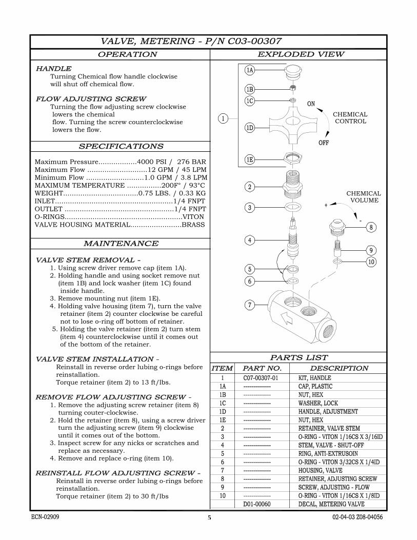
WEIGHT...................................0.75 LBS. / 0.33 KG
Minimum Flow ...........................1.0 GPM / 3.8 LPM
OUTLET ...................................................1/4 FNPTINLET.......................................................1/4 FNPT
O-RINGS.......................................................VITON
MAXIMUM TEMPERATURE ................200F° / 93°C
Maximum Flow ............................12 GPM / 45 LPM
VALVE HOUSING MATERIAL........................BRASS
CHEMICALVOLUME
CHEMICALCONTROL
1. Using screw driver remove cap (item 1A). 2. Holding handle and using socket remove nut (item 1B) and lock washer (item 1C) found inside handle. 3. Remove mounting nut (item 1E). 4. Holding valve housing (item 7), turn the valve retainer (item 2) counter clockwise be careful not to lose o-ring off bottom of retainer. 5. Holding the valve retainer (item 2) turn stem (item 4) counterclockwise until it comes out of the bottom of the retainer.
Reinstall in reverse order lubing o-rings before reinstallation. Torque retainer (item 2) to 13 ft/lbs.
1. Remove the adjusting screw retainer (item 8) turning couter-clockwise. 2. Hold the retainer (item 8), using a screw driver turn the adjusting screw (item 9) clockwise until it comes out of the bottom. 3. Inspect screw for any nicks or scratches and replace as necessary. 4. Remove and replace o-ring (item 10).
Reinstall in reverse order lubing o-rings before reinstallation. Torque retainer (item 2) to 30 ft/lbs
- Turning Chemical flow handle clockwise will shut off chemical flow.
- Turning the flow adjusting screw clockwise lowers the chemical flow. Turning the screw counterclockwise lowers the flow.
Maximum Pressure..................4000 PSI / 276 BAR
5

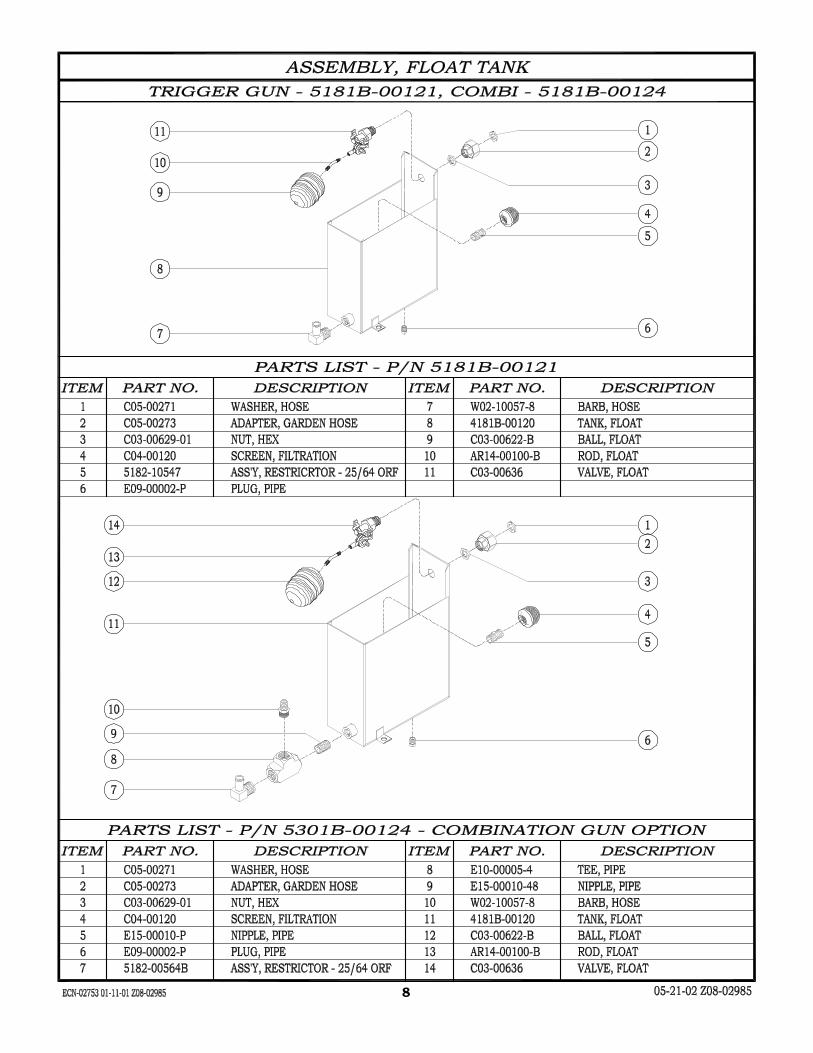
12-12-02 Z08-00064SECN-02897 Supersedes 09-00 Z08-00064 6

09-00 Z08-00064ECN-02311 7
8
9

10

11

12
13
GAS VALVE SERVICING
IMPORTANT SAFETY INSTRUCTIONS
FUEL SAFETY
DANGER: To avoid possible injury, fire, or explosion, please read and follow
these instructions. N.G. (Natural) gas is lighter than air and will generally rise through the venting and escape harmlessly.
L.P. (Propane) gas is heavier than air and like water, will flow to the lowest level. Before lighting the pilot burner, sniff at the lowest level. If you smell gas, follow these rules:
1. Get all the people out of the building.
2. DO NOT light matches. DO NOT turn electric switches or light switches on or off in the area. DO NOT use an electric fan to remove gas from the area.
3. Shut off the gas supply from the outside of the building.
4. Telephone (from another location) Gas Company and Fire Departments. Ask instructions. DO NOT go back into the building..
1. QUALIFIED PERSONNEL AND LOCAL CODES: All installation and servicing must only be performed by qualified personnel and must conform to the local codes and with the Natural Fuel Gas Code (ANSI Z223.1/NFPA No. 54).
2. GAS AND ELECTRICITY: Gas and electricity must be shut off when installing or servicing. Turn back on to test or operate.
3. FIRE HAZARD: Keep combustible materials away from gas machines. DO NOT allow lint or dust collect in the burner area.
4. N.G. AND L.P.: Caution must be taken to ensure no raw gas is present in the surrounding area before attempting to put the machine into operation, or when relighting pilot.
LIQUID PROPANE & NATURAL GAS VALVE
5. GAS SUPPLY: Do not connect the machine to supply piping before testing gas supply pressure. Excessive pressure may cause damage to gas control valve. This machine must have a fuel supply as specified in the FUEL section of the MODEL SPECIFICATIONS
SAVE THESE SAFETY
INSTRUCTIONS
GENERAL INFORMATION
1. LEAK TEST: All gas connections should be tested for leaks per the LEAK TEST instructions.
2. CONVERTING N.G. to L.P.: The regulator and vent tube must be removed, a plate installed in it’s place, a regulator added to the incoming supply line, and main burner and pilot orifice changed.
3. CONVERTING L.P. to N.G.: A regulator must be installed on the gas valve, a vent tube added, and main burner and pilot orifice changed.
4. L.P. FIRED MACHINES: As weather gets colder, the rate of liquid being vaporized into gas in the fuel storage tank will decrease. The storage tank(s) must be sized sufficiently large enough to ensure an adequate supply of vaporized fuel at all anticipated outdoor temperatures. Your L.P. supplier can recommend the correct tank(s) knowing the piping layout and the BTU demand found in MODEL SPECIFICATIONS.
5. FUEL OUTAGE: If your L.P. tank runs out of fuel or if the natural gas supply is interrupted, turn off the gas at the machine. After L.P. tank is filled, or the natural gas is restored, relight pilot per LIGHTING PILOT instructions.
6. WATER EXPOSURE: If your gas control valve has been exposed to water in any way, do not attempt to use it. It must be replaced. Do not attempt to repair the gas control valve.
10-00 Z08-00163 ECN-02375 Supercedes 05-86 Z08-00163

14
RELIGHTING PILOT
1. Partially depress and turn gas control valve knob to “Off” position.
2. Wait at least 5 minutes to allow gas to escape the burner compartment.
3. See LIGHTING PILOT section above.
PRESSURE REGULATOR ADJUSTMENT NOTE: Pressure regulator is normally preset at factory. However, field adjustment may be accomplished as follows:
1. Monometer or attachment may be accomplished at pressure tap port.
2. Remove plug on top of regulator.
3. Rotate the adjustment screw “clockwise” to increase or “counterclockwise” to decrease pressure. See MODEL SPECIFICATIONS for proper pressure setting.
4. Replace plug securely.
NOTE: This regulator is normally used with a Natural Gas machine, L.P. Gas fired machine requires a regulator on the incoming supply line.
LEAK TEST 1. Use soapy water or leak detecting solution
(never a match or open flames) when checking for leaks.
2. Apply the water or solution over the connections and observe carefully to see if bubbles expand, indicating a leak is present. A large leak can blow the solution away before the bubbles have a chance to form.
3. To correct leak, try tightening first. If leak continues, take the connection apart and inspect the threads. Replace defective items.
4. If step 3 doesn’t correct the problem, look for sand holes in the pipe or fittings. If found replace the complete device.
LIGHTING PILOT 1. Turn on the line valve.
2. Set the temperature control (if so equipped) to the lowest setting.
3. Turn on the gas control valve knob to “Pilot” position.
4. Depress and hold knob down while lighting pilot. Allow pilot to burn 1/2 minute before releasing valve knob. If pilot does not remain lit, repeat the operation allowing a longer period before releasing. If pilot still does not remain lit or does not light, the pilotcouple may be defective and needs to be replaced. (if pilot adjustment is necessary see “PILOT FLAME ADJUSTMENT”.
5. Turn knob to “ON” position.
6. Set temperature control ( if so equipped) to the desired temperature position. NOTE: Do Not use knob on gas control valve to adjust gas flow. Turn to full “ON”. Do Not adjust gas input between “PILOT” and “ON” positions of the knob.
PILOT FLAME ADJUSTMENT
1. Remove machine screw located next Remove machine screw located next to the pilot connection. Be careful not to lose the gasket.
2. Turn the recessed screw clockwise to reduce the pilot flame and counter-clockwise to increase the pilot flame.
3. With gasket in place, replace machine screw securely over adjustment screw.
10-00 Z08-00164 ECN-02375 Supercedes 05-86 Z08-00164
N.G. VENT CONNECTION 1/8” O.D. TUBING
N.G. PRESSURE REGULATOR
ADJUSTMENT
OUTLET
PRESSURE TAP
PORT 1/8”
INLET
THERMOCOUPLE CONNECTION
PILOT FLAME ADJUSTMENT
PILOT OUTLET 1/4” O.D. TUBING
1/2” FEMALE CONDUIT

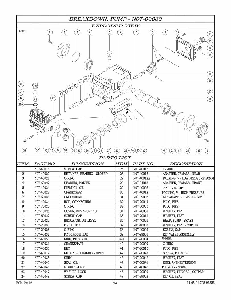
PART LISTS
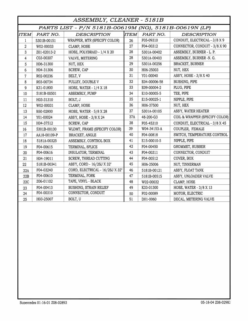
ITEM PART NUMBER PART DESCRIPTION QTY.
1 AP12-00102 PIPE, HRS 42 E04-00005-48 BUSHING, PIPE 13 E04-00006-48 BUSHING, PIPE 14 E08-00016-4 ELBOW, 1/2FNPT 15 E10-00005-4 TEE, PIPE 16 E11-00015-4 TEE, PIPE 17 E13-00010-48 NIPPLE, PIPE - 1/4" 18 E15-00010-58 NIPPLE, HEX 19 E15-00018-48 NIPPLE, BRASS 1/2" 110 E15-00045-2 NIPPLE, PIPE - GS 111 F04-00762 SWITCH, VACUUM 112 H04-31504 SCREW, CAP 413 H05-31300 WASHER, FLAT - 5/16 814 H05-31304 WASHER 415 N07-00060 PUMP, WATER - TS1021 116 N07-40046-P MOUNT, PUMP w/HOLE 117 R03-00794 PULLEY, DBL 118 R04-00001 BUSHING, PULLEY 119 W02-10016-8 BARB, HOSE 120 W02-10025-8 BARB, HOSE 121 W02-10040-8 BARB, HOSE 1
1120
4 10
6
19 3 21
72
5
9 8
15
13
1
13 16
14 12
17
18
SUPERCEDES 03/23/01 Z08-02986
ASSEMBLY, PUMP
EXPLODED VIEW - P/N 5181B-00501
11/22/2005 Z08-02986
36
3775
105
176
71
176 106204
310
1913
M10 X 1.5
153042103
145
1398 126
224
105
12
159
11 8
2724
12
353
13
14

OIL LEVEL
TOOL KITS
PACKING EXTRACTION KIT - P/N Z09-00028
COMPLETE TOOL KIT - P/N Z09-00021
VALVE SERVICE
1. Remove the plugs holding the valve assemblies.
2. Remove and discard o-rings from the plugs. Cleanplugs with solvent or soap and water. Allow todry.
3. Using a needle nose pliers, fingers, or hookshaped tool, remove the valve assemblies fromthe head. Remove and discard the o-rings fromthe valve assemblies and/or head. Examine eachvalve assembly and discard damaged parts. Referto the ”PUMP BREAKDOWN” for part numbersof any replacement items.
4. Clean any accumulated debris from the valvecavities and flush with water.
5. Wash the valve assemblies in clean water andrinse. While still wet, test each valve assemblyby sucking on the valve seat. A properly sealingvalve will allow a good vacuum to be developedand maintained, while a malfunctioning valve willnot. Good valve assemblies should be set asidefor installation in step 7.
6. Malfunctioning valve assemblies mustbe replaced.
7. Lubricate a new o-ring with the pump crankcaseoil and install into valve cavity in the head. Installa good valve assembly into the cavity as illus-trated.
8. Lubricate a new o-ring with pump crankcase oiland place on a plug cleaned in step 2 above.
9. Install a plug into the pump head. Tighten plugby hand.
10. Torque the plug to the value indicated in the“TORQUE” section of the pump specifications.
11. Repeat steps 7 through 11 for remainingvalve assemblies.
HEAD REMOVAL
1. Remove the cap screws holding the pump headto the crankcase. A metric tool is required forthis step. Be careful not to lose the washer oneach cap screw.
2. Remove the head by rotating the crankshaft andtapping the head away from the crankcase witha soft mallet. Keep rear surface of thehead parallel to the front surface of the crankcaseto prevent binding on the plungers.
3. Once the head is removed, protect the plungersfrom damage.
GENERAL PUMP MAINTENANCE
07-23-03 Z08-00063ECN-02981 Supersedes 11-14-02 Z08-00063
13
62
7
6
15

PLUNGER SERVICE
1. Remove pump head per “HEAD REMOVAL”.
2. Remove any packings and retainers left on theplungers by pulling them straight off.
3. Examine each plunger, looking for a smoothsurface free of any scoring, cracks, or pitting.Any defective plungers should be removed per“PLUNGER REMOVAL”.
4. Discard and replace any defective plungers.
5. Reinstall the plunger per“PLUNGER INSTALLATION”.
6. Reinstall head per “HEAD INSTALLATION”.
PLUNGER REMOVAL
NOTE: When the plunger screw is removed, it isimportant to install new o-ring, anti-extrusion,and copper washers.
1. Remove the plunger screw is removed, it isimportant to install new o-ring, anti-extrusion,and copper washers.
2. Remove the plunger retaining screw by turningcounterclockwise. Remove and replace copperwasher.
3. Remove and discard o-ring and anti-extrusionring from retainer screw.
4. Remove the plunger from the cross head andexamine it for cracks, scoring, or pitting.
5. Remove and discard copper flinger washer, cleanwith solvent and allow to dry.
PLUNGER INSTALLATION
1. Install the copper flinger washer onto the crosshead.
2. Slide the plunger onto the crosshead.
3. Lubricate an o-ring with crankcase oil and installinto the groove on the plunger screw. Install theanti-extrusion ring into the groove next to the o-ring. Note: The o-ring should be nearest thescrew head and the anti-extrusion ring nearestthe threads.
4. Apply a drop of thread sealant to the threads ofthe retainer screw.
5. Thread the plunger retainer screw into the crosshead making sure the copper flat washer isinstalled onto the screw.
6. Torque the plunger retainer screw to the valueindicated in the torque section of the pumpspecifications.
PACKING SERVICE
1. Remove the head per “PUMP HEAD REMOVAL”.
2. Remove any packings and female adapters lefton the plungers by pulling them straight off.Insert proper packing extractor onto theextractor hammer. Insert packing extractor andtool through the packings and adaptersremaining in the head. Tighten the hammer andremove the remaining items in the head. Removepackings and o-rings from adapters. Discard theo-rings and packings.
3. Clean the packing canities in the head and rinsewith clean water.
4. Clean exposed plungers. Clean male and femaleadapters with soap and water and allow to dry.
5. Examine male and female adapters, discard wornitems. Trial fit the female adapters into the head
GENERAL PUMP MAINTENANCE
07-23-03 Z08-00063AECN-02981 Supersedes 11-14-02 Z08-00063A 16

GENERAL PUMP MAINTENANCE
07-23-03 Z08-00063BECN-02981
checking for binding or damage. Discard andreplace damaged items.
6. Lubricate packing cavities in the head and allpackings and adapters with pump crankcase oil.
7. Lay head on the bench with packing cavities up.Install one male adapter in each cavity with theflat side down.
8. Install one v-packing into each cavity with thelips pointing down. A packing insertion too ofthe appropriate size is recommended for thisoperation.
9. Install the restop ring with the lips pointingdown.
10. Install a front female adapter into each cavitywith the flat side up. Make certain the adaptergoes all way down into the cavity.
11. Install the low pressure packing with the flatside down.
12. Install the rear female adapter into each cavitywith the lips pointing down.
13. Lubricate o-rings with pump crankcase oil andinstall one into the groove of each adapter.
14. Install one adapter and o-ring into each cavitywith the flat side up. Each adapter and o-ringassembly should push into the head toapproximately 1/16 inch of being flush with thesurface of the head. Only hand pressure shouldbe required to perform this operation. This stepis VERY IMPORTANT. If the rear female adapterdoes not fit almost flush, something is notproperly positioned. If a proper fit is obtained,proceed to step 16. If a proper fit is not obtained,remove the female adapters from the offendingcavity and reinstall items per steps 8 through15.
15. Install head per “HEAD INSTALLATION”.
HEAD INSTALLATION
1. Prepare pump head per instructions in“PACKING SERVICE”.
2. Rotate the plungers so the outer plungers areprojecting the same distance from the crankcase.
3. Lubricate the exposed plungers with crankcaseoil.
4. Start the head onto the plungers and using asoft mallet, tap the head evenly until it comes incontact with the crankcase.
5. Start the cap screws through the head and intothe crankcase. Do not forget the lock washer oneach screw.
6. Tighten all cap screws by hand.
7. Torque the cap screws to the value indicated inthe “TORQUE” section of PUMPSPECIFICATIONS. Torque the cap screws in theorder listed below.
7
82
46
71
35
13
62
7
6
17
18

PUMP TROUBLESHOOTING
08-27-03 Z08-00195ECN-02981 Supersedes 06-00 Z08-00195
TROUBLE POSSIBLE CAUSE REMEDY
1. Oil leaking in the area of water pump crankshaft.
A. Worn crankshaft seal.B. Bad bearing.C. Grooved shaft.D. Failure of retainer o-ring
A. Remove and replace.B. Remove and replace.C. Remove and replace.D. Remove and replace.
2. Excessive play on crankshaft.
A. Defective bearings.B. Excess shims.
A. See "Worn bearing".B. Set up crankshaft.
3. Loud knocking in pump.
A. Loose conecting rod screws.
B. Worn connecting rod.
C. Worn bearings.
D. Loose plunger bushing screw.
A. Tighten connecting rod screws per PUMP SPECIFICATIONS.B. Replace connecting rod per PUMP MAINTENANCE.C. Replace bearings per PUMP MAINTENANCE.D. Tighten plunger screw per PUMP SPECIFICATOINS.
4. Oil leaking at the rear portion of the pump.
A. Damaged or improperly installed oil gauge window gasket.B. Damaged or improperly installed rear cover.C. Oil gauge loosed.D. Rear cover screws loose.
E. Pump overfilled with oil, displaced through crankcase breather hole in oil cap/dipstick.
A. Replace gasket or o-ring.
B. Replace gasket or o-ring.
C. Tighten oil gauge.D. Tighten rear screws. to torque values in PUMP SPECIFCATIONS. SE. Drain oil: refill to recommended oil level as stated in OIL LEVEL in PUMP MAINTENANCE.
5. Water in crankcase A. May be caused by humid air condensing into water inside the crankcase.B. Worn or damaged plunger screw o-ring.
A. Maintain or step up lubrication schedule.
B. Remove and replace. See PLUNGER SERVICE in PUMP MAINTENANCE.
6. Worn bearing A. Excessive belt tension.
B. Oil contamination.
A. See BELT TENSION in MACHINE MAINTENANCE.B. Check oil type and change intervals per PUMP SPECIFICATIONS.
7. Short bearing life A. Excessive belt tension.
B. Misalignment between pump and motor.C. Oil has not been changed on regular basis.
A. See BELT TENSION in MACHINE MAINTENANCE.B. Re-align pump and motor.
C. Check oil type and change intervals per PUMP SPECIFICATIONS.
8. Short seal life A. Damaged plunger bushing.B. Worn connecting rod.C. Excess pressure beyond the pump's maximum rating.D. High water temperature.
A. Replace punger bushing.B. Peplace connecting rod.C. Match pressure stated in PUMP SPECIFICATIONS.D. Lower water tempersture stated in PUMP SPECIFCATIONS.
19
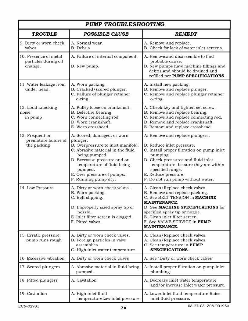
PUMP TROUBLESHOOTING
08-27-03 Z08-00195AECN-02981
TROUBLE POSSIBLE CAUSE REMEDY
9. Dirty or worn check valves.
A. Normal wear.B. Debris
A. Remove and replace.B. Check for lack of water inlet screens.
10. Presence of metal particles during oil change.
A. Failure of internal component.
B. New pump.
A. Remove and disassemble to find probable cause.B. New pumps have machine fillings and debris and should be drained and refilled per PUMP SPECIFICATIONS.
11. Water leakage from under head.
A. Worn packing.B. Cracked/scored plunger.C. Failure of plunger retainer o-ring.
A. Install new packing.B. Remove and replace plunger.C. Remove and replace plunger retainer o-ring.
12. Loud knockingnoise in pump
A. Pulley loose on crankshaft.B. Defective bearing.C. Worn connecting rod.D. Worn crankshaft.E. Worn crosshead.
A. Check key and tighten set screw.B. Remove and replace bearing.C. Remove and replace connecting rod.D. Remove and replace crankshaft.E. Remove and replace crosshead.
13. Frequent or premature failure of the packing
A. Scored, damaged, or wornplunger.B. Overpressure to inlet manifold.C. Abrasive material in the fluid being pumped.D. Excessive pressure and or temperature of fluid being pumped.E. Over pressure of pumps.F. Running pump dry.
A. Remove and replace plungers.
B. Reduce inlet pressure.C. Install proper filtration on pump inlet pumping.D. Check pressures and fluid inlet temperature; be sure they are within specified range.E. Reduce pressure.F. Do not run pump without water.
14. Low Pressure A. Dirty or worn check valves.B. Worn packing.C. Belt slipping.
D. Improperly sized spray tip or nozzle.E. Inlet filter screen is clogged.F. Pitted valves.
A. Clean/Replace check valves.B. Remove and replace packing.C. See BELT TENSION in MACHINEMAINTENANCE.D. See MACHINE SPECIFICATIONS forspecified spray tip or nozzle.E. Clean inlet filter screen.F. See VALVE SERVICE in PUMPMAINTENANCE.
15. Erratic pressure: pump runs rough
A. Dirty or worn check valves.B. Foreign particles in valve assemblies.C. High inlet water temperature
A. Clean/Replace check valves.A. Clean/Replace check valves.C. See temperature in PUMP SPECIFICATIONS.
16. Excessive vibration A. Dirty or worn check valves A. See "Dirty or worn check valves"
17. Scored plungers A. Abrasive material in fluid being pumped.
A. Install proper filtration on pump inlet plumbing
18. Pitted plungers A. Cavitation A. Decrease inlet water temperature and/or increase inlet water pressure.
19. Cavitation A. High inlet fluid temperatureLow inlet pressure.
A. Lower inlet fluid temperature.Raise inlet fluid pressure.
20

21

**
**
**
**
**
*23
21OUT
**
3231
30
29
28
27
26
25
14 13 12 11
24
22
20
19
18
17
16
15
10
9
8
7
6
5
4
3
2
1
**
22
23
24

FROM
MOTOR CORD
POWER CORD
POWER CORD
MOTOR CORD
GASVALVE
TEMPFROM
CONTROL
FROM
SWITCHVACUUM

PUMP MOTOR
230 VAC
LINE
2
LINE
1
EQUIPMENT
GROUND
230VAC
SWITCHVACUUM
grn
grn
blkwht/red
red blk
wht/red
blkblk
blk blkwht/ CAMSWITCH
grn
blk
PUMP MOTOR
230 VAC
LINE
2
LINE
1
EQUIPMENT
GROUND
230VAC
SWITCHVACUUM
grn
grn
blkwht/red
red blk
wht/red
wht/blkblk
wht
blk
CAMSWITCH
grn
blk
PUMP MOTOR
230 VAC
LINE
2
LINE
1
EQUIPMENT
GROUND
230VAC
grn
grn
blkwht/red
red blk
wht/red
blk
wht
CAMSWITCH
GASCONTROL230 VAC
grn
blk
CONTROLTEMP
CONTROL230 VAC
GAS
wht
blkGAS
230 VACCONTROL
ES-00174
ES-00173
ES-00171
15