specifications section 02510 water … interior: lined with double thickness cement and seal coated:...
TRANSCRIPT

SPECIFICATIONS SECTION 02510
WATER DISTRIBUTION SYSTEM PART 1 GENERAL 1.1 DESCRIPTION
A. Section includes requirements to furnish, construct, and test piping for water supply and distribution system, including fire protection.
1.2 REQUIREMENTS FOR MANUFACTURERS AND SUPPLIERS AND CONTRACTORS
BEFORE DELIVERY A. Conduct quality assurance for furnished pipe, fittings, and valves following standards
specified herein. B. Commission may inspect materials, including in-plant testing of valves, following Section
01450. C. Quality assurance for precast concrete utility structures is specified in Section 03400. D. Tapping Contractor: Performed successful pressure taps on cast iron, ductile iron pipe
(DIP), prestressed concrete cylinder pipe (PCCP), or polyvinyl chloride (PVC) water mains.
E. PVC pipe manufactured more than 12 months prior to installation will not be accepted.
F. Qualifications for linestop tapping equipment installer:
1. Experience: Actively engaged in linestop installation for minimum of 3 years, with at least 5 projects in the last 3 years of similar size and type.
2. Field supervisory personnel: Experienced in performance of work and tasks stated herein for minimum of 3 years.
1.3 SUBMITTALS
A. Submit following Section 01330.
1. Manufacturer's shop drawings showing valves, operators, gear ratios, design flows, and pressure differential, performance charts, and parts list for all valves 16 inch and larger.
2. Working drawings and calculations for pipes with welded on thrust rings. 3. Proposed temporary bypass piping system.
a. Catalog data for pipe material. b. Working drawings and description of sizes and locations.
4. Product data and coating procedure for surface preparation, prime coat and finish coat application for PCCP adapters.
July 2011 02510-1

5. Manufacturer’s shop drawings for linestop installation, including but not limited to: pipe taps, drilling apparatus, linestops, tapping valves and all other equipment and materials necessary to complete the work.
6. Waiver for pipe and fittings, valves, precast concrete structures and welded on thrust rings: Submit letter naming the manufacturer who has on file with the Commission a certified standard drawing containing required Commission approved information. Provide new submittals if specifications change.
B. Submit following Section 01450 on Contractor provided materials.
1. Certificates of Compliance or Materials Checklist Furnished by the Commission, for all applicable materials specified herein.
2. Manufacturer's Certified Test Reports: a. Valves 16 inches and larger:
1) Tests specified in the referenced standards. 2) Tests performed on valves and valve operators.
C. Tapping Sleeve and Valve or Tapping Assembly and Valve: Submit before main is
tapped. 1. Installation and testing instructions. 2. Recommended maximum test pressure and length of time for testing assembly using
water as test medium.
D. Tapping Assemblies for PCCP 16 inch and Larger: Submit product data and coating procedure for surface preparation, prime coat and finish coat applications for steel coated with shop coat primer.
E. Submit manufacturers' installation instruction for PVC pipe and fittings, joint restraint
devices, and manufacturer's instructions for tapping pipe.
F. Submit for information only: 1. Contractors Experience and Supervisory Field Personnel for Linestop Tapping
Equipments/Installer. a. Presentation of similar experience in the last 3 years.
1) Include, but not limited to, owner name, address, telephone number, contact person, date and duration of work, location, pipe information, and contents handled by the pipeline.
b. Supervisory field personnel and historical information of linestop experience. c. At least one of the field supervisors listed must be at site when linestop
operations are in progress. 2. Submit copies of WSSC approved tapping card, MDE Sediment and Erosion Control
Certification and American Traffic Safety Services Association (ATSSA) flagger certification.
1.4 STORAGE AND HANDLING
A. Engineer will inspect materials on site before installation following Section 01450.
July 2011 02510-2
B. Loading, unloading, handling, inspection, and storage of pipe, fittings, valves, joint accessories, and appurtenances: Follow AWWA C600 and AWWA C605, and as specified herein.
C. Storage: Store pipe, fittings, valves, and appurtenances off ground using sound wood
blocks placed on stable foundation or using other appropriate means. Allow space between rows, individual pieces and bundles with clearance below and above to allow full view for inspection purposes. 1. Store in well-drained area away from brush and accessible for inspection. 2. Do not stack pipe higher than 54 inches high. 3. Keep spigot ends of pipe clean and clear for dimensioning purposes. 4. Do not place excavated or other material over or against stored material. 5. PVC pipe:
a. Store so it does not deform or bend. b. Pipe stored outdoors or otherwise exposed to direct sunlight: Cover with canvas
or other opaque material with provision for adequate air circulation. D. Handling: Unload and handle materials with crane, backhoe, or equipment of adequate
capacity, equipped with appropriate slings or padding to protect materials from damage. E. Repair or Replacement:
1. Repair damages or defects following approved manufacturer's recommendations. 2. Remove and replace at no cost to the Commission materials deemed not repairable.
PART 2 PRODUCTS
2.1 MATERIALS
A. Pipe and Fittings: 1. General:
a. Provide pipe and fittings of same size and material by same manufacturer, marked with manufacturer's name or trademark.
b. Bolts and nuts: Marked, cast, or forged with identification of material and producer. Painted markings are not acceptable.
c. The Commission will furnish: 1) Mechanical joint and/or push on joint ductile iron pipe and mechanical joint
bell end only fittings 14 inch and smaller Class 54 and the following appurtenances thereto: a) Glands, gaskets, nuts and bolts for mechanical joints b) Gaskets and lubricants for push-on joints. c) Long type solid sleeves.
2) Fire hydrants and the following appurtenances thereto: Anchoring coupling or anchoring tee a) Fire hydrant strapping appurtenances except 3/4-inch threaded bars,
bolts and nuts. 3) Mechanical joint valves 14-inch and smaller diameter including valve boxes
therefore and 16" x 14" reducers when required to install valves.
July 2011 02510-3

4) Manhole and vault frames and covers except for hatches and partial valve boxes which shall be furnished by the Contractor. See Section 05500 for requirements.
5) Tapping sleeves and valves for existing DIP and CIP 24 inch and smaller mains with valves sizes 14 inch and smaller.
6) Tapping assemblies and valves for existing PCCP 16 inch to 24 inch mains with valves sizes 14 inch and smaller.
7) Corporation stops and couplings for 3/4, 1, 1-1/2 and 2-inch diameter taps. 8) 3/4, 1, 1-1/2 and 2-inch diameter copper pipe and the following
appurtenances thereto: a) Copper to copper couplings b) Copper to galvanized couplings c) Compression joints d) Tees, 1" x 3/4" x 1"; 1" x 1" x 1"; 1-1/2" x 1-1/2" x I", 1-1/2" x 3/4"
brass screwed. 9) Meter yoke setters, 3/4", 1”, 1-1/2” and 2". 10) Angle valve, 2". 11) Brass nipple and brass fittings. 12) Service saddles for water mains 3-inch through 12-inch, except for PVC. 13) Curb stops, 3/4", 1", 1-1/2", 2". 14) Meter housings for 5/8" thru 1-1/2" meters including frame and cover. 15) Materials for house connections with outside meters 2-inch and larger
diameter except meter vault. 16) Reducing coupling, 1-1/2" x 1". 17) Meters. 18) Tiebolts and except for PVC, retainer glands and wedge action restrainer
glands for harnessing joints on pipe 14-inch and smaller diameter. 19) Reducers with either end larger than 14-inch diameter: Furnished by
Contractor except when required for 14-inch diameter valves furnished by the Commission. 16 inch by 14 inch reducer will have Mechanical joint bell ends.
20) Valve box complete. 21) Curb box complete for house connection renewals. 22) Air valve, 2” 23) Polyethylene flat tube encasement for 14-inch and smaller ductile iron pipe. 24) Polyethylene compatible adhesive tape for use with Polyethylene flat tube
encasement. d. To obtain material furnished by the Commission, the Contractor shall notify and
make arrangements with the Commission's warehouse as specified in Section 01110. 1) The Commission will arrange for Contract site delivery when the quantity
of pipe comprises a truckload lot or more. When material is delivered directly to the job site, the Commission will so notify the Contractor at least 24 hours before delivery. The Contractor shall unload and store the material to the satisfaction of the Engineer.
2) Pipe and fittings delivered direct to work site will be inspected prior to installation and will be marked either with WSSC'S logo, which means acceptable and ready for installation, or REJECTED-R which means it is rejected for installation until repaired by the manufacturer or
July 2011 02510-4

2. DIP: a. Mechanical or push on joints: AWWA C151
1) Coatings: a) Exterior: Asphalt coated: AWWA C111 b) Interior: Lined with double thickness cement and seal coated: AWWA
C104. 2) Class: Unless otherwise shown on Drawings, follow Special Thickness
Class in AWWA C151, minimum Class 54 for 4 inch and larger. 3) Lengths:
a) 18 to 20 feet. b) Pipe provided for installation on curved alignment: Pipe lengths that
will not require joint to be deflected more than 80 percent of manufacturer’s recommendation.
4) In addition to markings required in AWWA C151, for pipe 36 inch and larger diameter, clearly mark manufacturer's pipe control number on each pipe length on face or near inside of bell.
5) Imperfections: a) Wrinkles or dimples:
(1) On spigot sealing surface: Unacceptable. (2) On bell and contour: Acceptable to depth of 3/16 inch, provided
minimum metal thickness under imperfection is maintained. (3) On pipe barrel: Acceptable to depth of 1/16 inch, provided
minimum wall thickness requirements are met. b) Laminations: On spigot sealing surface and those greater than 1/16
inch in depth on remaining outside surface of pipe: Unacceptable. c) Pinholes: Acceptable when minimum wall thickness for designated
class is maintained. 6) Approved manufacturers:
a) American Cast Iron Pipe Co. b) Atlantic State Cast Iron Pipe Co. (Division of McWane, Incorporated). c) Clow Water Systems Company; (Division of McWane Incorporated). d) Griffin Pipe Products, Inc. e) McWane Cast Iron Pipe Company (Division of McWane
Incorporated). f) United States Pipe and Foundry Co.
b. Fittings: For use on ductile iron bell, mechanical, or push on joint, unless shown otherwise on Drawings or Standard Details. 1) Size, dimensions, and tolerances: AWWA C110 or AWWA C153. 2) Mechanical joint solid sleeves: AWWA C110 or AWWA C153. 3) Unless shown otherwise, furnish fittings 3 inch through 24 inch diameter
having minimum pressure rating of 350 psi, and furnish fittings larger than 24 inch diameter having minimum pressure rating of 250 psi.
4) Mechanical joints: See Joint Material. 5) Coatings:
a) Exterior: Asphalt coated outside: AWWA C111.
July 2011 02510-5

b) Interior: Lined with double thickness cement and seal coated: AWWA C104 and C111.
c) Or, exterior and interior: Fusion bond epoxy coated: AWWA C116. 6) Fittings 36 inch and larger diameter: In addition to cast markings required
in AWWA C110 and C153, clearly stencil on with waterproof paint on each fitting the year, month, and day cast, lot number, and manufacturer's fitting control number.
7) Approved manufacturers: a) American Cast Iron Pipe Co. b) Clow Water Systems Company, (Division of McWane Incorporated). c) Griffin Pipe Products Co. d) Tyler Pipe Industries, Inc. e) Union Foundry Company, (Division of McWane, Incorporated). f) United States Pipe and Foundry Co. g) SIGMA Corporation. h) Star Pipe Products.
c. Flanged Pipe And Fittings: 1) Flanged pipe: AWWA C115 and requirements for pipe above.
a) Approved Manufacturers for Flanged Pipe: (1) American Cast Iron Pipe Company. (2) Clow Water Systems Company, (Division of McWane
Incorporated). (3) Fast Fabricators, Inc. (4) Rhawn Flange Co. (5) United States Pipe and Foundry Co. (6) Atlantic State Cast Iron Pipe Co. (Division of McWane,
Incorporated). (7) Griffin Pipe Products, Inc. (8) McWane Cast Iron Pipe Company (Division of McWane
Incorporated). 2) Flanged fittings: AWWA C110 and requirements for fittings above except
for flanged joints. a) Flanges for fittings: Cast integrally with body and with same thickness
over their entire circumference. (1) Faces: Perpendicular to axis of pipe. (2) Bolt holes: Equally centered and spaced. (3) Joint accessories: See Joint Material.
b) Approved Manufacturers for Flanged Fittings: (1) American Cast Iron Pipe Company. (2) Clow Water Systems Company, (Division of McWane
Incorporated). (3) Fast Fabricators, Inc. (4) Rhawn Flange Co. (5) United States Pipe and Foundry Co. (6) Atlantic State Cast Iron Pipe Co. (Division of McWane,
Incorporated). (7) Griffin Pipe Products, Inc.
July 2011 02510-6

(8) McWane Cast Iron Pipe Company (Division of McWane Incorporated).
(9) Star Pipe Products. (10) Sigma Corporation.
c) Blind flanges for entry ports: Steel following AWWA C207 (1) Drill for bolt circle to match flange on entry port tee. (2) Class D for total pressures (operation plus surge) up to 150 psi. (3) Class E for total pressures (operation plus surge) up to 275 psi. (4) Class F for total pressures (operation plus surge) up to 300 psi.
d. Welded-on Connections (Bosses or Outlets) 8 Inch Diameter and Smaller: For DIP 24 inch and larger diameter when shown on Drawings, Standard Details, or when Contractor chooses welded on connections instead of AWWA C110 tee fittings. 1) Mechanical Joint or Flanged Joint: See Joint Material 2) Coatings:
a) Exterior: Asphaltic coated outside following AWWA C110 or, b) Interior:
(1) Line welded-on bosses with liquid epoxy coating, certified by NSF, contact with potable water.
(2) Line welded-on outlets with double thickness cement and seal coat: AWWA C104.
c) Mainline pipe: Sufficient thickness to meet Class specified, including within heat affected area: (1) Welded-on bosses, minimum Class 53 or as shown on Drawings. (2) Welded-on outlets, minimum Class 53 or as shown on Drawings. (3) Minimum Charpy impact value is 10 foot-pounds. (4) Has passed 300 psi hydrostatic test without leakage.
d) Approved manufacturers, welded-on bosses: (1) American Cast Iron Pipe Company. (2) Clow Water Systems Company (Division of McWane
Incorporated). (3) United States Pipe and Foundry Co.
e) Approved manufacturer, welded-on outlets: (1) American Cast Iron Pipe Company
3. PVC Pipe and Fittings a. Pipe 12 inch and smaller: AWWA C900, 14 inch and larger: AWWA C905 as
modified herein or unless otherwise indicated elsewhere in Contract Documents, suitable for potable water use. 1) Class and thickness: DR18 or as noted on the drawings, with DIP
equivalent outer diameters. 2) Potable water use: NSF61. 3) Pipe markings: AWWA C900 and AWWA C905 4) Joining pipes: Utilize elastomeric gasket push on joints following AWWA
C900 and AWWA C905 5) Approved Manufacturers:
a) IPEX. b) Uponor ETI. c) JM EagleTM.
July 2011 02510-7
d) Diamond Plastics Corp. e) Freedom Plastics, Inc. f) National Pipe & Plastics, Inc. g) North American Pipe Corp. h) Royal Plastics Group, Ltd.
b. Fittings: 1) Ductile iron specified herein. 2) Push-on rubber gasketed joints: Injection-molded meeting AWWA C907,
Class 150, or fabricated meeting AWWA C900, Class 200 or AWWA C905, Class 235.
3) Approved Manufacturers: a) Harrington Corporation (Harco), Multifittings. b) Freedom Plastics.
4. Tapping sleeves for existing gray iron, ductile iron, and PVC pipe 36 inch and smaller. a. Cast from gray iron or ductile iron or material manufactured from ASTM A283
Grade C, ASTM A36, or equal. b. Full sleeve type (with test plug) capable of containing pressure with full volume
of sleeve. c. Gaskets butt against existing pipe ensuring a watertight seal. d. Suitable for use with Class AB or CD cast iron pipe or ductile iron for sizes 12
inches and smaller without changing either half of sleeve, unless field measurements are taken for type and outside diameter of existing pipe.
e. Rated at minimum 200 psi water working pressure for 12 inch and smaller diameter sleeves and minimum 150 psi working pressure for 14 inch to 24 inch.
f. Capable of withstanding rated working pressure without leakage past side and end gaskets and no leakage at junction of the two.
g. Mechanical Joint: 1) Bolts, hexagonal nuts, rubber gaskets, and other accessories: AWWA C111,
except provide only high strength low alloy steel bolts. h. Valve flange:
1) Suitable for connecting to mating end of tapping valve, which has a raised face to ensure true alignment of valve and tapping machine, following Manufacturers Standardization Society (MSS) SP60.
2) AWWA C207 Class D, Class E, or Class F (match tapping valve flange) for material manufactured from ASTM A283 Grade C, ASTM A36, or equal.
i. Coatings and linings: 1) Gray or ductile iron casted tapping sleeves AWWA C110. 2) Material manufactured from ASTM A283 Grade C, ASTM A36, or equal
tapping sleeves. a) Interior Lining: Fusion bonded epoxy that is EPA or NSF approved for
contact with potable water, a minimum thickness of 12 mils, following AWWA C213.
b) Exterior Coating: Fusion bonded epoxy, a minimum thickness of 12 mils, following AWWA C213.
j. Approved manufacturers: 1) American Flow Control, Series 2800C and 1004. 2) Clow Valve Company (A Division of McWane Inc.), Figure FS5205.
July 2011 02510-8

3) M&H Valve Company (A Division of McWane Inc.), Style 1574 and 1674. 4) Mueller Company, Style H-615-24. 5) Tyler Pipe/Utilities Division. 6) United States Pipe and Foundry Co., Ductile Iron T-9. 7) JCM Industries, Inc., Nash, Texas, Number JCM 412 Fabricated Steel
Tapping Sleeves. 5. Tapping sleeves for existing gray iron or DIP larger than 36 inch:
a. Material manufactured from ASTM A283 Grade C, ASTM A36, or equal. b. Full sleeve type capable of containing pressure with full volume of sleeve. c. Gaskets butt against existing pipe providing watertight seal. d. Rated at minimum 150 psi water working pressure. e. Capable of withstanding rated working pressure without leakage past the side
and end gaskets and no leakage at the junction of the two. f. Furnish test plug on sleeve for field pressurization of sleeve, valve, and tapping
machine assembly before making tap. g. Interior Lining: Lined with fusion bonded epoxy that is EPA or NSF approved
for contact with potable water, minimum thickness of 12 mils, following AWWA C213.
h. Exterior Coating: Fusion bonded epoxy, a minimum thickness of 12 mils, following AWWA C213.
i. Mechanical joint bolts, hexagonal nuts, rubber gaskets and all other accessories: AWWA C111, except provide only high strength low alloy steel bolts.
j. Gasket material: AWWA C111. k. Valve flange:
1) Manufactured: AWWA C207 Class D, Class E, or Class F (match tapping valve flange).
2) Suitable for connecting to mating end of tapping valve, which has raised male face to ensure true alignment of valve and tapping machine, following MSS SP60.
3) Bolts, nuts and studs: High strength, low alloy, ANSI A21.11 for end flange joints.
l. Marking on sleeve: Manufacturer's name or logo and barrel and outlet diameters, at a minimum. Either cast or stenciled with waterproof paint and all markings must be legible.
m. Approved manufacturers: 1) JCM Industries, Inc., Nash, Texas.
a) Number JCM .412 ESS Fabricated Steel Tapping Sleeves. b) Number JCM 414 ESS Fabricated Mechanical Joint Tapping Sleeves.
2) Romac Industries, Inc., Seattle, Washington, Number FTS425 Steel Fabricated Tapping Sleeve.
6. Tapping Assemblies for Prestressed Concrete Cylinder Pipe 16-inch and Larger: a. Designed to withstand total pressure (operating plus surge). b. Saddle Plates: Manufactured from ASTM A285 Grade C, ASTM A36 or equal. c. Gasket: Broad, flat sealing surface and material suitable for potable water
ranging in temperature from 32 degrees F to 110 degrees F. d. Valve flange:
1) Manufactured: AWWA C207, Class E or F (match tapping valve flange).
July 2011 02510-9

2) Suitable for connecting to mating end of tapping valve, which has raised male face to ensure true alignment of valve and tapping machine following MSS SP60.
3) Bolts, nuts and studs: High strength, low alloy, ANSI A21.11. e. Welds.
1) I nterior lining: Dye-penetrate inspected for watertightness. 2) Certified welders: AWWA C301, Section 1.9.2.
f. Interior lined with cement mortar or fusion bonded epoxy: EPA or NSF approved for contact with potable water, minimum thickness of 15 mils, following AWWA C213.
g. All other steel coated with shop coat primer. h. Sleeve.
1) Provide separate gland, which allows sleeve to be installed and annular space between pipe and sleeve to be grouted, before cutting prestressing wires.
2) Use foam grouted gaskets and hard rubber spacers, to provide annular space between pipe and sleeve.
3) Grout after sleeve is installed. 4) Sleeves furnished with grout horns to facilitate grouting annular space.
i. Grout: Quick-set cement mortar which does not contain calcium chloride or other material that can contribute to corrosion of existing prestressing wire. 1) Approved manufacturer and product:
a) Sika Corporation, Sikaset NC, b) Or equal.
j. Gland: 1) Equipped with load bearing set screws to transfer thrust from branch to
sleeve. 2) Welding gland to steel cylinder of pipe to provide watertight seal will not
be permitted. k. Encase sleeve in minimum of 1 inch of cement mortar minimum strength 3000
psi, without calcium chlorides, after tap. l. Approved manufacturers:
1) Price Brothers Pressure Pipe Division. 2) JCM Industries, Inc., Nash, Texas, Number JCM 415, Type 1. 3) Romac Industries, Inc., Seattle, Washington, Number FTS435, Style 1.
7. Adapters: PCCP to DIP. a. Approved Manufacturer: Price Brothers for PCCP to DIP 16 inches through
54 inches diameter. b. Construction: AWWA C301.
1) Welding: AWS D1.1. 2) Steel cylinder: Designed to withstand total pressure (working and surge
pressure) or 275 psi, whichever is greater, following Barlow Formula. a) Maximum allowable steel stress: 0.50 of steel yield stress. b) Minimum steel cylinder thickness: 1/4 inch.
3) Loads for adapters longer than 3'-0": Designed for external loads following AWWA Manual M-11.
4) Adapter ends: Compatible with mating pipe ends. 5) Required accessories: Complete with bolts, nuts, gaskets, and diapers.
July 2011 02510-10

6) Flanges: Designed for total pressure or surge of 275 psi, whichever is greater, and matching bolt size, bolt hole diameter, and bolt hole circle of mating flange.
c. Shop Coatings. 1) Machined surface: Coat with one coat of Porter Guard Alkyd Zinc Dust
Coating No. 299. 2) Steel surfaces: Coat with liquid epoxy that is certified by NSF for contact
with potable water. d. Shop Surface Preparation and Coating Application: AWWA C210.
1) Liquid epoxy coating systems for interior and exterior of steel component pipelines: AWWA C210.
2) Approved finish coats: a) Tnemec Series 139 Pota-pox II. b) PorterLine 6000. c) Carboline Super Hi-gard 891. d) Tnemec Series N140 Pota-pox Plus. e) Or equal.
8. Linestop. a. General.
1) Rated at minimum working pressure of 150 psi and hydrostatic test pressure of 300 psi.
2) Lined waterways with fusion-bonded epoxy, EPA or NSF approved for potable water, minimum thickness of 12 mils, following AWWA C213.
3) Exterior coating: Fusion bonded epoxy minimum thickness 12 mils, following AWWA C-213.
4) Bolts, nuts and studs: High strength, low alloy following ANSI A21.11. b. Tapping Saddle Assembly.
1) Full encirclement, consisting of, at minimum, upper saddle plate with anchor neck, lower saddle plate, tapping flange and nozzle with gland or gasket for pressure tight seal suitable for potable water ranging in temperature from 32 degrees F to 100 degrees F. All components properly shaped and adequate strength to ensure proper mounting and pressure tight seal around existing pipe.
2) Saddle plates manufactured from ASTM A283 Grade C, ATSM A36 or equal steel, clean and sound without defects that impact their service. No plugging or welding of such defects will be allowed.
3) Outlet flange manufactured of same material as tapping saddle assemblies: Flat face and drill following ANSI B16.5, Class 150 flange. Provide suitable independently operating locking device in periphery of flange to secure completion plug.
4) All waterways: Dye-penetrant inspected for watertightness. c. Completion Plug:
1) Manufactured from ASTM A283 Grade C, ASTM A36 or equal steel. 2) Equipped with two circumferential grooves; one to receive the locking
device from flange, and second to contain compressible "O" ring to seal pressure tight against interior diameter of nozzle.
d. Blind Flange:
July 2011 02510-11

1) To seal tapping saddle assembly upon removal of tapping and linestop equipment.
2) Manufactured from AWWA C207, Class D steel and drilled to match bolt circle of nozzle of tapping saddle assembly.
e. Linestop Machine: 1) Tapping Equipment Fabricator/Installer: Furnish folding plug head linestop
capable of pressure tight seal against inside diameter of existing pipe. 2) Linestop: Advance into and retract from pipeline by means of hydraulic or
mechanical actuator. When retracted the folding plug head to be housed in pressure tight chamber between the actuator and tapping valve.
3) Folding plug: Capable of displacing accumulated grit deposits in interior of the pipe while advancing to its linestopping position and have molded polyurethane sealing element around its perimeter and supply workable seal with interior diameter when fully advanced.
f. Approved Tapping Equipment Fabricator/Installers: 1) Hydra-Stop Services 2) Flowserve US, Inc. 3) Or Equal.
9. Copper Pipe and Fittings. a. Pipe: Seamless, type K, and following ASTM B88. b. Fittings: Copper following ASTM B62 and AWWA C800.
1) Copper to Copper Couplings: 2 part type consisting of tubing connection, coupling nut, and friction ring. a) Copper tube end of couplings: Flare or compression connection type
for connecting to type K copper service pipe. b) Opposite end, and all couplings nuts: Threaded following AWWA
C800, flare or compression connection for connecting type K copper service pipe.
2) Thread iron pipe ends of all copper to iron pipe fittings following American National Pipe Threads.
3) Approved manufacturers: a) Ford Meter Box Company, Inc., flare, threaded or ‘Q’ compression. b) Mueller Company, flare, threaded or 110 compression. c) A.Y. McDonald Manufacturing Company, flare, threaded or ‘Q’
compression. d) Cambridge Brass, flare, threaded or ‘Q’ compression.
c. Compression Joints. 1) Approved manufacturers:
a) Ford Meter Box Company, Inc., Q Compression. b) Mueller Company, 110 Compression. c) A.Y. McDonald Manufacturing Company, ‘Q’ Compression. d) Cambridge Brass, Q Compression.
d. Copper to copper couplings. 1) Approved manufacturers:
a) A.Y. McDonald Manufacturing Company Catalog No. 4756, 4758 4753Q, 4754Q and 4758Q.
b) Ford Meter Box Company, Inc. Series CS-22, C22, C44-Q, C84Q and C14-Q.
July 2011 02510-12

c) Mueller Co. Catalog No. H-15405, H-15403, H-15428 and H-15451. d) Cambridge Brass No. 117-H and 119-H.
e. Copper and Brass Fittings: Standard seamless threaded, reamed, and chamfered, of size required. 1) Approved manufacturers:
a) A.Y. McDonald Manufacturing Company. b) Ford Meter Box Company, Inc. c) Mueller Co. d) Lee Brass Co. e) Merit Brass Co.
f. Service Insulator Assemblies. 1) Approved manufacturers:
a) Mueller Insulated Products, Mueller Co. for 1-inch Service Insulator. b) Ford Meter Box Company, Inc. for 1-1/2, and 2 inch Service Insulator. c) A.Y. McDonald Manufacturing Company for Dielectric Bushing
Assembly. d) Cambridge Brass.
10. Service Saddles: a. General:
1) Use for 2 inch and smaller connections. 2) Manufacture saddles with clamps for underground services:
a) Rated for minimum service of 150 psi. b) Provide full support around the circumference of pipe. c) Do not distort, scratch, or damage pipe when tightened. d) Contains thick tapping boss, which has been precision-machined with
full-length threads for watertight connection that resists pullout. e) Threads: AWWA C800 with standard corporation stop thread. f) Brass or bronze alloy meeting ASTM B62 or B584 and AWWA C800. g) Castings:
(1) Uniform quality, true to pattern, of even grain, sound and smooth, and without cold shuts, swells, scales, blisters, sand holes, cracks or other defects.
(2) Surfaces: Smooth with no burnt-on sand. h) Use watertight gaskets of Buna-N rubber meeting ASTM D2000 or
nitrile around tap hole. b. Saddles for Cast Iron or DIP.
1) Approved manufacturers and models for 3 inch: a) Ford Meter Box Co., Inc., Style No. FC202 Double Strap b) JCM Industries, Inc., Model No. 406-0413 Double Strap. c) Mueller Company, Catalog No. DR 2S0356 Double Strap. d) Smith-Blair, Inc., Model Nos. 317-000-41309-000, 317-000-41313-000,
and 317-000-41315-000, all Double Strap. 2) Approved manufacturers and models for 4 inch and above:
a) Ford Meter Box Co., Inc., Style No. 202B Double Strap. b) Mueller Company, Catalog No. BR2B Double Strap. c) A.Y. McDonald Manufacturing Company Catalog No. 3825 Double
Strap. c. Saddles for PVC AWWA C900 and C905 Pipe.
July 2011 02510-13
1) Use tapping saddle manufactured specifically for AWWA C900 and C905 PVC pipe with stainless steel wide band straps, nuts and washers.
2) Approved Manufacturers and Models: a) Ford Meter Box Co., Inc. 202BS. b) Smith Blair, Inc., 325. c) Mueller Company, Series DR2S. d) A.Y. McDonald Manufacturing Company, Model 3845.
d. Saddles for PCCP. 1) Approved manufacturer:
a) JMC Industries, Inc., Model 425 ESS B. Joint Material:
1. Push on and Mechanical Joints: AWWA C111, C110, C153, C900, and C905. a. Mechanical joints: High strength low alloy steel tee head bolts. b. Gaskets: AWWA C111
1) Nitrile (NBR) Gaskets, if specified on Drawings: ANSI/AWWA C111/A211.11
2. Flanged Joints: AWWA C110, AWWA C115, and specified herein. a. Flange bolts, nuts, and washers: Carbon steel ASTM A307, Grade B. b. Nuts: Cold punched, hexagonal, trimmed, and chamfered. c. Heads, nuts and threads: ANSI B1.1. d. Bolts: 1/4-inch projection beyond nut when joint with gasket is assembled. e. Gaskets: Full-faced, 1/8-inch thick rubber. f. When flange joints are required for connecting to Class 250 gate valves with
flanges, follow ANSI B16.1, Class 250, flat face flanges, unless otherwise specified.
3. Mechanical Couplings: Heaviest standard type for each size without pipe stops and following Drawings. a. Approved manufacturers:
1) Cascade Waterworks Mfg. Co., Style CDC. 2) Dresser Manufacturing Division, Dresser Style No. 138. 3) Powerseal Pipeline Products Corporation, Style No. 3501 Straight
Coupling. 4) Romac Industries, Inc., Style 400. 5) Smith-Blair, Inc. (formerly Rockwell International), Model No. 441.
4. Joint Restraining Material: a. Tie bolt with companion washers and bolts: Manufactured by Star National
Products or equal. 1) 3/4-inch Super Star Tiebolt SST-7 for pipe joints 4 through 12-inch
diameter. 2) Super Star Tiebolt SST- 753 for pipe joints 14 through 24-inch diameter.
b. Steel for strapping and harnessed joints: Minimum 3/4-inch diameter and following ASTM A588 and A307.
c. Wedge action restrainer glands: 1) Approved manufacturers for DIP Mechanical Joint:
a) EBAA Iron, Inc., MEGALUG Series 11XX-DEC (with Mega-bond), b) Ford Meter Box Company, Inc., UNI-FLANGE Series UFR1400-DA-
XX- (I or U) (with E-Coat),
July 2011 02510-14
c) Romac Industries, Inc., ROMAGRIP Series XX-RAP (with E-Coat) d) SIGMA Corporation, ONE LOK Series SLDE-XPXX (with Corrsafe
Coating System), e) Star Pipe Products, STARGRIP, Series 3000-XX with accessories,
(with Starbond Coating System). f) Tyler Union, Tuf Grip Series TLD-XX-FBE with accessories (with E-
coat). 2) Approved manufacturers for PVC Pipe:
a) UniFlange, Series 1500. b) EBAA Iron, Series 2000PV. c) Capital Industries, EZ Lok 4 inch through 12 inch diameter. d) Or equal.
d. Restrained joint for PVC Pipe push-on joint: Meet Uni-B-13. 1) Approved manufacturers:
a) JCM 620 Sur-Grip. b) EBAA Iron, Series 1600. c) UniFlange, Series 1390-C. d) Or equal.
2) Do not deflect PVC pipe in restrained joints. If deflection is required in restrained joint, use ductile iron pipe and fittings.
e. Push on restrained joint gasket for 4 inch through 24 inch DIPs. 1) Approved manufacturers:
a) United States Pipe and Foundry Co., FIELD LOK 350 for use with TYTON JOINT pipe.
b) American Cast Iron Pipe Co., Fast-Grip for use with Fastite pipe. c) McWane Cast Iron Pipe Co., Sure Stop 350 for use with TYTON
JOINT pipe. f. Restrained proprietary push on joint pipe and fittings: 16 inch and larger DIP.
1) Approved manufacturers: a) American Cast Iron Pipe Co.:
(1) Flex-Ring Joint, 16 inch through 36 inch. (2) Lok-Ring Joint, 42 inch through 54 inch.
b) United States Pipe and Foundry Co., TR Flex Joint, 16 inch through 54 inch.
c) Clow Water Systems Company (Division of McWane, Incorporated), Super Lock 16 inch through 30 inch.
d) Griffin Pipe Products Co., Snap-Lok, 16 inch through 24 inch. e) McWane Cast Iron Company (Division of McWane, Incorporated),
McWane restrained joint for Fastite joint pipe, 36 inch. g. Restraint of Field Cut Proprietary Restrained Joint Pipe, 16 Inch and Larger
Diameter DIP. 1) Approved manufacturers:
a) American Cast Iron Co., Field Flex-Ring, 16 inch through 36 inch. b) United States Pipe and Foundry Co., TR Flex Gripper Ring, 16 inch
through 36 inch. c) Griffin Pipe Products Co., Snap-Lok FC Field Cut Kit, 16 inch through
24 inch. h. Anchor Coupling and Anchoring Tee: Ductile iron minimum pressure rating 250
July 2011 02510-15

1) Joint: Mechanical joint with integrally cast standard mechanical joint, rotatable glands on each end that has lock against joint separation.
2) Anchor Coupling Length: 12 to 13 inches. 3) As manufactured by approved fitting manufacturers listed herein.
C. Valves:
1. Gate Valves, sizes 3 inch through 14 inch: Designed, built and tested following AWWA C509 or AWWA C515 except as modified herein. a. Working pressure rating: 250 psi. b. General configuration:
1) Non-rising stem, resilient seated design for installation in horizontal or near horizontal pipe lines.
2) Operated with AWWA, 2 inch square operating nut turned counterclockwise to open.
c. Valve stem material: ASTM B763, UNS alloy C99500 minimum yield strength (determined as stress producing an elongation under load of 0.5 percent, which is 0.01 inches in gage length of 2.0 inches) of 40,000 psi.
d. Valve stem extension: Follow Standard Details. 1) Approved manufacturer:
a) The General Engineering Company. b) Or equal.
e. Corrosion resistant coating: 1) Follow AWWA C550 and NSF 61 certified. 2) Minimum 8 mils dry film thickness. 3) Fusion bonded epoxy applied to all ferrous metal surfaces after rendering
surfaces free from grease, dirt and moisture, and performing near-white, blast cleaning following SSPC-SP10/NACE 2.
4) Do not coat fasteners or machined surfaces subject to contact and relative movement against other surfaces during operation of valve or other surfaces where such coating would compromise proper installation or functionality of valve.
f. Externally accessible bolts, nuts and washers: Type 304 Stainless steel. g. Direct buried valves:
1) Mechanical joint ends following AWWA C111. 2) Non-adjustable, elastomeric stem seals.
a) Adjustable packing glands not permitted for direct buried applications. 3) Direct operation of stem from above via 2 inch square nut.
a) No gear box provided. 4) Approved Manufacturers and Models:
a) American Flow Control Series 2500. b) Clow Valve Co. Figure No. F-6100 of Model 2638 or 2639. c) Kennedy Valve Co. Figure No. 8571 or 7571 d) M & H Valve Co. Style 4067-01 or 7571. e) Mueller Company Catalog No. A-2360-2 or A-2361-2 f) U.S. Pipe, Valve and Hydrant Division Catalog No. A-USPO-2 or A-
USP1-2. h. Non -Direct buried valves.
July 2011 02510-16

1) Vertical orientation required. 2) Flanged ends: ANSI B16.1 Class 125 or Class 250 if specified on
Drawings. 3) Pipe plugs in valve body:
a) Minimum ½ inch for valve sizes up to 4 inches. b) Minimum ¾ inch for valve sizes larger than 4 inch. c) Solid brass installed with Teflon tape seal on threads.
4) Direct operation of stem from above via 2 inch square nut. a) No gear box provided.
5) Approved Manufacturers and Models: a) American Flow Control Series 2500. b) Clow Valve Co. Figure No. F-6102 of Model 2638 or 2639. c) Kennedy Valve Co. Figure No. 8561 or 7561 d) M & H Valve Co. Style 4067-02 or 7561. e) Mueller Company Catalog No. A-2360-6 or A-2361-6. f) U.S. Pipe, Valve and Hydrant Division Catalog No. A-USPO-6.
i. Tapping Valves. 1) Direct Buried: Vertical orientation required. 2) Waterway sized to provide clearance for tapping machine cutter with
minimum diameter 1/2 inch less than size of valve. 3) Inlet end.
a) Flange: ANSI B16.1 Class 125 or Class 250 if specified on Drawings. b) Flange with face having annular projection (configured following
Manufacturers Standardization Society of Valve and Fitting Industry, SP-60) to center the valve in the recess of tapping sleeve flange (for gray iron and ductile iron pipe) or tapping assembly (for PCC pipe)
4) Outlet end: Mechanical joint following AWWA C111. 5) Direct operation of stem from above via 2 inch square nut.
a) No gear box provided. 6) Approved Manufacturers and Models:
a) American Flow Control Series 2500. b) Clow Valve Co. Figure No. F-6114 of Model 2638 or 2639. c) Kennedy Valve Co. Figure No. 8590 of Model KS-FW or KS-RW d) M & H Valve Co. Style 4751-01 or 7950. e) Mueller Company Catalog No. T-2360-16 or T-2361. f) U.S. Pipe, Valve and Hydrant Division Catalog No. T-USPO-1.
2. Gate Valves, sizes 16 inch through 48 inch for normal working pressure applications. a. Designed, built and tested following AWWA C500 except as modified
herein. b. Working pressure rating: Minimum 150 psi. c. General configuration:
1) Non-rising stem, metal seated, parallel, double disc design for installation in horizontal or near horizontal pipe lines.
2) Operated with AWWA, 2 inch square operating nut turned counterclockwise to open.
d. Valve Stem extension: Follow Standard Details. 1) Approved manufacturer:
a) The General Engineering Company.
July 2011 02510-17

b) Or equal. e. Corrosion resistant coating:
1) Follow AWWA C550 and NSF 61 certified. 2) Minimum 8 mils dry film thickness. 3) Tnemec N140-1211 epoxy or Amerlock 2 red oxide epoxy by Ameron
International applied in two coats to interior and exterior ferrous metal surfaces after rendering surfaces free from grease, dirt and moisture, and performing near-white, blast cleaning following SSPC-SP10/NACE 2.
4) Do not coat fasteners or machined surfaces subject to contact and relative movement against other surfaces during operation of valve or other surfaces where such a coating would compromise the proper installation or functionality of the valve.
f. Externally accessible bolts, nuts and washers: Type 304 Stainless steel. g. Non-Direct buried.
1) Horizontal orientation required. 2) ANSI B16.1 Class 125 flanges.
h. Pipe plugs: 1) Minimum 3/4 inch solid brass. 2) Install with Teflon tape seal on threads.
i. Gear case: Following AWWA C500. Sealed, grease filled with bevel gearing operated from above via 2 inch square nut. Acceptable gear ratios:
Valve Size Ratio Valve Size Ratio 16” 2:1 to 4:1 30” 4:1 to 6:1 18” 3:1 to 4:1 36” 4:1 to 6:1 20” 3:1 to 4:1 42” 6:1 to 8:1 24” 3:1 to 4:1 48” 8:1
j. Bypass gate valve: Following AWWA C500.
1) Locate at end of body opposite stem location. 2) Operation of bypass from above via 2 inch square nut.
k. Rollers, tracks and scrapers required or rolling disc design with tracks and scrapers acceptable in lieu of separate rollers on disc.
l. Approved Manufacturers and Models: 1) American R/D 52. 2) Clow Valve Co. Figure No. F-5070. 3) Kennedy Valve Co. Style No. C561/F5070 4) Ludlow Rensselaer Division of Patterson Pump Co. Model List 13. 5) Mueller Company Catalog No. 2380.
m. Tapping Valves. 1) Waterway sized to provide clearance for tapping machine cutter with
minimum diameter 1/2 inch less than size of valve. 2) Non Direct Buried.
a) Horizontal orientation required. b) Inlet end.
(1) ANSI B16.1 Class 125 flange. (2) Annular projection valve sizes 14 inch and larger.
July 2011 02510-18

(a) Outside diameter of annular projection to be 0.063 inches less than inside diameter of recess in tapping sleeve flange.
(b) Extend 0.188 inches beyond flange face of valve. (3) Flange with face having annular projection (configured following
Manufacturers Standardization Society of Valve and Fitting Industry, SP-60) to center valve in recess of tapping flange (for gray iron and ductile iron pipe) or tapping assembly (for PCC pipe)
c) Outlet end: ANSI B16.1, Class 125 flange for connection to tapping adapter.
d) Gear case: AWWA C500. Sealed, grease filled with bevel gearing operated from above via 2 inch square nut. Acceptable gear ratios:
Valve Size Ratio Valve Size Ratio
16” 2:1 to 4:1 30” 4:1 to 6:1 18” 3:1 to 4:1 36” 4:1 to 6:1 20” 3:1 to 4:1 42” 6:1 to 8:1 24” 3:1 to 4:1 48” 8:1
3) Bypass gate valve: Following AWWA C500.
a) Locate at end of body opposite stem location. b) Operation of bypass from above via 2 inch square nut.
4) Rollers, tracks and scrapers required or rolling disc design with tracks and scrapers acceptable in lieu of separate rollers on disc.
5) Submit pertinent provisions listed herein following Section 01330. 6) Approved Manufacturers and Models:
a) American R/D 52. b) Ludlow Rensselaer Division of Patterson Pump Co. Model List 13.
3. Gate Valves, sizes 16 inch through 48 inch for high working pressure applications. a. Designed, built and tested following AWWA C500 except as modified
herein. b. Working pressure rating: Minimum 250 psi. c. General Configuration:
1) Non-rising stem, metal seated, parallel, double disc design for installation in horizontal or near horizontal pipe lines.
2) Operated with AWWA, 2 inch square operating nut turned counterclockwise to open.
d. Non-Direct buried only. 1) Horizontal orientation required. 2) ANSI B16.1 Class 125 or 250 flanges as indicated on Drawings.
e. Valve Stem extension: Follow Standard Details. 1) Approved manufacturer:
a) The General Engineering Company. b) Or equal.
f. Corrosion resistant coating: 1) Follow AWWA C550 and NSF 61 certified. 2) Minimum 8 mils dry film thickness.
July 2011 02510-19

3) Tnemec N140-1211 epoxy or Amerlock 2 red oxide epoxy by Ameron International: Applied in two coats to interior and exterior ferrous metal surfaces after rendering surfaces free from grease, dirt and moisture, and performing near-white, blast cleaning following SSPC-SP10/NACE 2.
4) Do not coat fasteners or machined surfaces subject to contact and relative movement against other surfaces during operation of valve or other surfaces where such a coating would compromise the proper installation or functionality of the valve.
g. Externally accessible bolts, nuts and washers: Type 304 Stainless steel. h. Pipe plug:
1) Minimum ¾ inch solid brass. 2) Install with Teflon tape seal in tapped boss on bonnet or body.
i. Gear case: Following AWWA C500. Sealed, grease filled with bevel gearing operated from above via 2 inch square nut. Acceptable gear ratios:
Valve Size Ratio Valve Size Ratio 16” 2:1 to 4:1 30” 4:1 to 6:1 18” 3:1 to 4:1 36” 4:1 to 6:1 20” 3:1 to 4:1 42” 6:1 to 8:1 24” 3:1 to 4:1 48” 8:1
j. Bypass gate valve: Following AWWA C500.
1) Locate at end of body opposite stem location. 2) Operation of bypass from above via 2 inch square nut.
k. Rollers, tracks and scrapers required or rolling disc design with tracks and scrapers acceptable in lieu of separate rollers on disc.
l. Manufacturers and Models: 1) American R/D 52. 2) Ludlow Rensselaer Division of Patterson Pump Co. Model List 14.
m. Tapping Valves. 1) Waterway sized to provide clearance for tapping machine cutter with
minimum diameter 1/2 inch less than size of valve. 2) Non-Direct buried.
a) Horizontal orientation required. b) Inlet end.
(1) ANSI B16.1 class 125 or 250 flange as indicated on Drawings. (2) Flange with face having annular projection (configured following
Manufacturers Standardization Society of Valve and Fitting Industry, SP-60) to center valve in recess of tapping flange (for gray iron and ductile iron pipe) or tapping assembly (for PCC pipe)
c) Outlet end: Following ANSI B16.1, class 125 or 250. Flange for connection to tapping machine adapter, as specified on Drawings.
d) Gear case: Following AWWA C500. Sealed, grease filled with bevel gearing operated from above via 2 inch square nut. Acceptable gear ratios:
Valve Size Ratio Valve Size Ratio
July 2011 02510-20

16” 2:1 to 4:1 30” 4:1 to 6:1 18” 3:1 to 4:1 36” 4:1 to 6:1 20” 3:1 to 4:1 42” 6:1 to 8:1 24” 3:1 to 4:1 48” 8:1
3) Bypass gate valve: Following AWWA C500.
a) Locate at end of body opposite stem location. b) Operation of bypass from above via 2 inch square nut.
4) Rollers, tracks and scrapers required or rolling disc design with tracks and scrapers acceptable in lieu of separate rollers on disc.
5) Approved Manufacturers and Models: a) American R/D 52. b) Ludlow Rensselaer Division of Patterson Pump Co. Model List 14.
4. Air Valve: Combining operating features of both an air/vacuum valve and air release
valve. a. Type: Universal/combination type following AWWA C512. b. Float, plug, guide shafts and bushings: Stainless Steel Type 316. c. Resilient seats: Buna-N. d. Metal internal parts and body only. e. Minimum orifice diameter as listed below the range of working pressure from 0
to 200 psi. 1) 3/16 inch for Crispin Valve. 2) 3/32 inch for APCO. 3) 3/32 inch for Val-Matic.
f. Inlet and outlet size: 2 inch NPT screwed connection. g. Internal body parts of valves: See interior coating of valves specified herein. h. Exterior coating of valves: Fusion bonded epoxy following AWWA C550. i. Approved manufacturers:
1) Crispin Valve Model No. UL-20. 2) APCO, Valve and Primer Corporation Model No. 145C. 3) Val-Matic Valve and Mfg. Corporation Model No. 202C.
5. Combination Air and Vacuum Valves, 3 inch and larger. a. Air and Vacuum Valve installed in combination with Air Release Valve, in
accordance with AWWA C512. 1) Air Release Valve piped out of side of air and vacuum valve, following
Standard Details. b. Float, plug, guide shafts and bushings: Stainless Steel Type 316. c. Resilient seats: Buna-N. d. Metal internal parts and body only. e. Size: Air and vacuum and air release valve following Drawings. f. Configuration: Connecting pipe and gate valve same size as air release valve
between combination air and vacuum valve and air release valve. g. Inlet and outlet size:
1) Air and Vacuum Valve: Inlet and outlet type following Drawings (ANSI B16.1, Class 125 or 250 flanges).
2) Air Release Valve: NPT screwed connection. h. Piping layout:
July 2011 02510-21

1) See Standard Details. 2) Pressure rating of gate valve: See Drawings.
i. Internal body parts of valves: See interior coating of valves specified herein. j. Exterior coating of valves: Fusion bonded epoxy following AWWA C550. k. Approved manufacturer:
1) Model number, outlet, and orifice following Drawings. a) Crispin Valve. b) APCO, Valve and Primer Corporation. c) Val-Matic Valve and Mfg. Corporation Model.
6. Pressure Reducing Valves. a. Maintain constant downstream pressure regardless of inlet pressure or flow
fluctuations. b. Design: To withstand and operate under non-shock working pressure of 180 psi. c. Valve size: 12 inch and smaller. d. Valve ends:
1) 4 inch and larger: Flange ends, see Joint Material. 2) 3 inch and smaller: NPT screwed connection.
e. Valve body: Ductile or Cast Iron with stainless steel trim internally. f. Pressure setting for valve: See Drawings. g. Reducing pilot control:
1) Body: Bronze with stainless steel valve seat ring and seat ring fasteners. 2) Piping and fittings: Bronze with copper. 3) External strainer and ball valves.
h. For valves 4 inches and larger: 1) Gage connections on inlet and outlet side. 2) Valve position indicator.
i. Internal body parts of valves: See interior coating of valves specified herein. j. Exterior coating of valves: Fusion bonded epoxy following AWWA C550. k. Approved Manufacturers:
1) Cla-Val Co., Model 90G-01ABS KC D.S. for 3 inch and smaller and Model 90G-01BCSY KC D.S. for 4 inch and larger.
7. Pressure Relief Valve. a. Normally closed.
1) Open when pressure at valve inlet increases above setting pressure. 2) Outlet side is atmospheric pressure.
b. Design: To withstand and operate under non-shock working pressure of 180 psi. c. Valve size: 12 inch and smaller. d. Valve ends: Flange ends, see Joint Material. e. Valve body: Ductile or cast iron with stainless steel trim internally. f. Pressure setting for valve: See Drawings. g. Relief pilot control:
1) Body: Bronze with stainless steel valve seat ring and seat ring fasteners. 2) Piping and fittings: Bronze with copper. 3) External strainer and ball valves.
h. Gage connection on inside side. i. Internal body parts: See internal coating of valves specified herein. j. Exterior coating: Fusion bonded epoxy following AWWA C550. k. Approved Manufacturers:
July 2011 02510-22

1) Cla-Val Co., Model 50-01BY KC D.S. 8. Flap Valve.
a. Allow passage of flow in one direction, while preventing reverse flow. b. Flange end: Class 125, ANSI B16.1, suitable for connecting to ductile iron
flange pipe. c. Approved manufacturers:
1) Clow Valve Company (Division of McWane, Incorporated), Model No. F-3012.
2) Tideflex Technologies, Inc., Series 35 with stainless steel backup ring. 9. Valve Boxes.
a. See Standard Details. b. Approved manufacturers:
1) Bingham and Taylor Corporation. 2) Bibby St. Croix Foundries, Inc. 3) Capitol Foundry of Virginia, Inc.
10. Interior Coating of Valves: Fusion bonded epoxy, certified by NSF for contact with potable water following AWWA C550.
11. Flange Bolt End Protection in Vaults: Plastic caps, shop or field filled with anti corrosion compound or lubricant. a. Approved Manufacturers:
1) Sap-Seal Products, Inc. 2) Advance Products & Systems, Inc. 3) Or equal.
12. Curb Stops: AWWA C800, except with working and test pressures below. Size In Inches Water Temperature Working Pressure Test Pressure 3/4, 1, & 1-1/4 Up to 100 degrees F Not less than 150 psi in
closed position Not less than 225 psi in open position
1-1/2 & 2 Up to 100 degrees F Not less than 200 psi in closed position
Not less than 300 psi in open position
a. Bronze: ASTM B62. b. Type of Ends:
1) Copper tube: Flare or compression connection type, fitted with coupling nuts threaded for use with copper service tube type K following ANSI/AWWA C800.
c. Compression Connection. 1) Approved Manufacturers and Models:
a) Ford Meter Box Co., Inc. Grip Joint. b) Mueller Co., Mueller 110 Compression joint. c) A.Y. McDonald Manufacturing Co., Q Series Compression.
d. Approved Curb Stop Manufacturers and Models: 1) A.Y. McDonald Manufacturing Company, Catalog No. 6100 and 6100Q. 2) Ford Meter Box Co., Inc. Catalog B22 Series and B44-G Series. 3) Mueller Co., Catalog No. H-1502-2, Catalog No. , Model No. H-15204
with check and B25209. 13. Corporation Stops: ANSI/AWWA C800, except with working and test pressures
below.
July 2011 02510-23
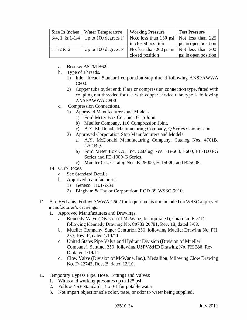
Size In Inches Water Temperature Working Pressure Test Pressure 3/4, 1, & 1-1/4 Up to 100 degrees F Note less than 150 psi
in closed position Not less than 225 psi in open position
1-1/2 & 2 Up to 100 degrees F Not less than 200 psi in closed position
Not less than 300 psi in open position
a. Bronze: ASTM B62. b. Type of Threads.
1) Inlet thread: Standard corporation stop thread following ANSI/AWWA C800.
2) Copper tube outlet end: Flare or compression connection type, fitted with coupling nut threaded for use with copper service tube type K following ANSI/AWWA C800.
c. Compression Connections. 1) Approved Manufacturers and Models.
a) Ford Meter Box Co., Inc., Grip Joint. b) Mueller Company, 110 Compression Joint. c) A.Y. McDonald Manufacturing Company, Q Series Compression.
2) Approved Corporation Stop Manufacturers and Models: a) A.Y. McDonald Manufacturing Company, Catalog Nos. 4701B,
4701BQ. b) Ford Meter Box Co., Inc. Catalog Nos. FB-600, F600, FB-1000-G
Series and FB-1000-G Series. c) Mueller Co., Catalog Nos. B-25000, H-15000, and B25008.
14. Curb Boxes. a. See Standard Details. b. Approved manufacturers:
1) Geneco: 1101-2-39. 2) Bingham & Taylor Corporation: ROD-39-WSSC-9010.
D. Fire Hydrants: Follow AWWA C502 for requirements not included on WSSC approved
manufacturer’s drawings. 1. Approved Manufacturers and Drawings.
a. Kennedy Valve (Division of McWane, Incorporated), Guardian K 81D, following Kennedy Drawing No. 80783 20781, Rev. 18, dated 3/08.
b. Mueller Company, Super Centurion 250, following Mueller Drawing No. FH 237, Rev. F, dated 1/14/11.
c. United States Pipe Valve and Hydrant Division (Division of Mueller Company), Sentinel 250, following USPV&HD Drawing No. FH 288, Rev. D, dated 1/14/11.
d. Clow Valve (Division of McWane, Inc.), Medallion, following Clow Drawing No. D-22742, Rev. B, dated 12/10.
E. Temporary Bypass Pipe, Hose, Fittings and Valves:
1. Withstand working pressures up to 125 psi. 2. Follow NSF Standard 14 or 61 for potable water. 3. Not impart objectionable color, taste, or odor to water being supplied.
July 2011 02510-24

F. Backflow Preventer and Basket Strainer for Temporary Water Main and Hydrostatic
Testing: Reduced pressure principal type, flanged and supplied complete with integral valves, following the American Society of Safety Engineers Standard No. 1013 and AWWA C510. 1. Materials: Bronze, or liquid epoxy coated cast iron body with bronze and stainless
steel working parts. 2. Pressure Requirements: Suitable for supply pressure as high as 175 psi and
hydrostatic test pressure of 350 psi. 3. Approved manufacturers:
a. Conbraco. b. Febco. c. Zurn Industries. d. Watts Regulator.
4. Basket Strainers. a. Installation: Inlet side of backflow preventer following Drawings. b. Strainers: Flanged ends, unless otherwise noted.
1) Strainer bodies: Ductile iron, gray iron, or bronze and designed to withstand maximum working pressure of 175 psi with tapped opening for flushing strained debris.
c. Screens: Unless otherwise noted, stainless steel or brass sheet metal with 1/4 inch perforations. 1) Open area of screen: At least 4 times inside cross-sectional area of pipe.
d. Approved manufacturers: 1) Hersey Products, Inc. 2) Mueller Co.
G. Meter Settings.
1. Meter Housings: a. Polyethylene Meter Boxes and Extensions.
1) Approved manufacturers: a) Oldcastle Precast, Inc.
(1) 24” x 20” Top, Model No. 202001 (2) 30” Dia. x 30” H, Model No. 302003 (3) 24” x 30” (H), Model No. 242003
b) DFW Plastics, Inc. (1) 24” x 20” Top, Model No. DFW242030TP (2) 30” Dia. x 30” H, Model No. DFW3030 (3) 24” x 30” H, Model No. DFW2430
c) Or equal. 2. Meter Setting Outside Water Meters:
a. Copper Pipe: Seamless, type K and following ASTM B88. b. Fittings and Accessories: Copper and 85-5-5-5 Red Brass following ASTM B62
and AWWA C800. c. Approved Manufacturers and Models:
1) Ford Meter Box Company. a) 3/4 inch Single Meter Yoke Setter, Model No. YA-3-95230-03,
adaptable for 5/8 inch meter using two Ford A13 meter adapters.
July 2011 02510-25
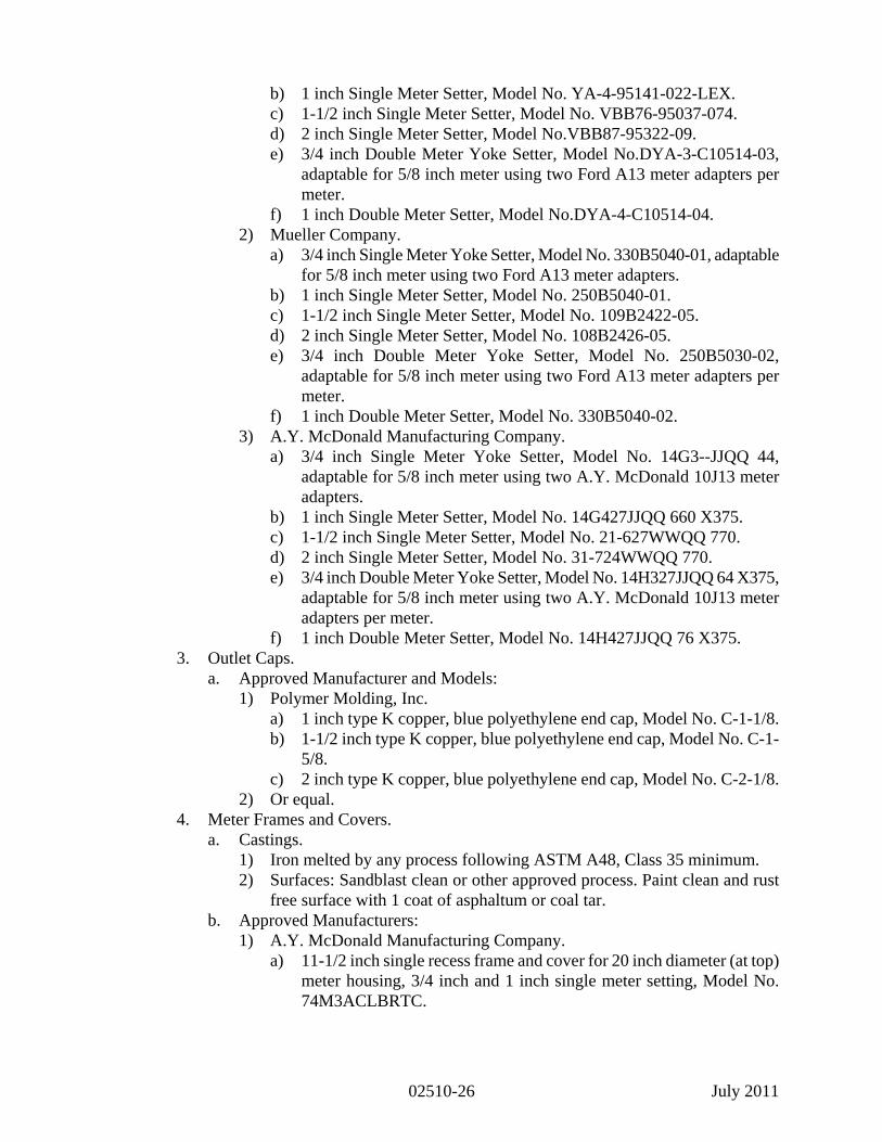
b) 1 inch Single Meter Setter, Model No. YA-4-95141-022-LEX. c) 1-1/2 inch Single Meter Setter, Model No. VBB76-95037-074. d) 2 inch Single Meter Setter, Model No.VBB87-95322-09. e) 3/4 inch Double Meter Yoke Setter, Model No.DYA-3-C10514-03,
adaptable for 5/8 inch meter using two Ford A13 meter adapters per meter.
f) 1 inch Double Meter Setter, Model No.DYA-4-C10514-04. 2) Mueller Company.
a) 3/4 inch Single Meter Yoke Setter, Model No. 330B5040-01, adaptable for 5/8 inch meter using two Ford A13 meter adapters.
b) 1 inch Single Meter Setter, Model No. 250B5040-01. c) 1-1/2 inch Single Meter Setter, Model No. 109B2422-05. d) 2 inch Single Meter Setter, Model No. 108B2426-05. e) 3/4 inch Double Meter Yoke Setter, Model No. 250B5030-02,
adaptable for 5/8 inch meter using two Ford A13 meter adapters per meter.
f) 1 inch Double Meter Setter, Model No. 330B5040-02. 3) A.Y. McDonald Manufacturing Company.
a) 3/4 inch Single Meter Yoke Setter, Model No. 14G3--JJQQ 44, adaptable for 5/8 inch meter using two A.Y. McDonald 10J13 meter adapters.
b) 1 inch Single Meter Setter, Model No. 14G427JJQQ 660 X375. c) 1-1/2 inch Single Meter Setter, Model No. 21-627WWQQ 770. d) 2 inch Single Meter Setter, Model No. 31-724WWQQ 770. e) 3/4 inch Double Meter Yoke Setter, Model No. 14H327JJQQ 64 X375,
adaptable for 5/8 inch meter using two A.Y. McDonald 10J13 meter adapters per meter.
f) 1 inch Double Meter Setter, Model No. 14H427JJQQ 76 X375. 3. Outlet Caps.
a. Approved Manufacturer and Models: 1) Polymer Molding, Inc.
a) 1 inch type K copper, blue polyethylene end cap, Model No. C-1-1/8. b) 1-1/2 inch type K copper, blue polyethylene end cap, Model No. C-1-
5/8. c) 2 inch type K copper, blue polyethylene end cap, Model No. C-2-1/8.
2) Or equal. 4. Meter Frames and Covers.
a. Castings. 1) Iron melted by any process following ASTM A48, Class 35 minimum. 2) Surfaces: Sandblast clean or other approved process. Paint clean and rust
free surface with 1 coat of asphaltum or coal tar. b. Approved Manufacturers:
1) A.Y. McDonald Manufacturing Company. a) 11-1/2 inch single recess frame and cover for 20 inch diameter (at top)
meter housing, 3/4 inch and 1 inch single meter setting, Model No. 74M3ACLBRTC .
July 2011 02510-26

b) 11-1/2 inch double recess frame and cover for 20 inch diameter (at top) meter housing, 3/4 inch and 1 inch double meter setting, Model No. 74M3ACLBRRTT.
c) 20 inch single recess monitor frame and cover for 30 inch diameter meter housing, 1-1/2 inch and 2 inch single meter setting, Model No. 74M30RTLB.
2) Bingham & Taylor Corporation. a) 11-1/2 inch single recess frame and cover for 20 inch diameter(at top)
meter housing, 3/4 inch and 1 inch single meter setting, Model No. BTA-3C/11 1/2 inch BTC3L-WS.
b) 11-1/2 inch double recess frame and cover for 20 inch diameter (at top) meter housing, 3/4 inch and 1 inch double meter setting, Model No. BTA-3C/11 1/2 inch BTC3L-WSDD.
c) 20 inch single recess monitor frame and cover for 30 inch diameter meter housing, 1-1/2 inch and 2 inch single meter setting, Model Nos. BTA2030MFC-WS and IND2030MFCWS.
3) Vestal Manufacturing Company. a) 11-1/2 inch single recess frame and cover for 20 inch diameter (at
top) meter housing, 3/4 inch and 1 inch single meter setting, Model No. 32-709 (BRMRC-20L W/LN W/RTR)
b) 11-1/2 inch double recess frame and cover for 20 inch diameter (at top) meter housing, 3/4 inch and 1 inch double meter setting, Model No.32-711 (BRMRC-20L W/LN W/2RTR).
c) 20 inch single recess monitor frame and cover for 30 inch diameter meter housing 1-1/2 and 2 inch single meter setting, Model No. 32-048(ER2030) and 32-479 (MONITOR R&C W/LN W/RTR).
H. Field Applied Coating: Cold applied petrolatum or petroleum wax.
1. Primer, Mastic, and Tape/wrap: AWWA C217 and manufactured for buried or submerged applications.
2. Petrolatum or Petroleum Wax Tape/Wrap: Minimum thickness of 40 mils. 3. Approved Manufacturers:
a. Central Plastics Company. b. Denso Incorporated. c. Tapecoat Company. d. Trenton Corporation.
I. Polyethylene Encasement: AWWA C105.
1. High-density cross-laminated polyethylene film (minimum 4 mil) or linear low-density polyethylene film (minimum 8 mil).
2. Polyethylene flat tube: Meet appropriate minimum width for size of pipe installed following AWWA C105, Method A, secured with polyethylene compatible adhesive tape.
3. Flat sheet polyethylene: Used for wrapping odd shaped appurtenances following AWWA C105, secured with polyethylene compatible adhesive tape.
J. Restrained Joint Pipe Tape.
1. Description:
July 2011 02510-27

a. Material: Non-detectable type, low density, virgin grade polyethylene, acid and alkali resistant; minimum wetting tension: 35 dynes/cm, ASTM D2578.
b. Tape Size: 6-inch width, 4 mils thickness. c. Printing: Two lines with minimum 1 inch height letters with “No-Dig Symbol”
following each cycle of text. 1) First line: “CAUTION-RESTRAINED JOINT PIPE” repeated every 20 to
24 inches. 2) Second line: “CALL WSSC 301-206-4002”
d. Colors: 1) Tape: APWA Red. 2) Lettering: Permanent Black.
2. Approved Manufacturers: a. Empire Level Manufacturing Corporation, Utility Products Division, Shieldtec
Underground Warning Tape. b. Blackburn Manufacturing Co., Inc., Non-Detectable Underground Utility
Warning Tape. c. Reef Industries, Inc. Terra Tape Standard Non-Detectable. d. Mutual Industries, Non-Detectable Underground Marking Tape. e. Pro-Line Safety Products (A Division of Pro-Pak Ind., Inc.), Standard Non-
Detectable. f. Or equal.
K. Tracer wire for PVC Pipe: TW, THW, THWN, or HMWPE insulated single-strand
copper, 10 gauge or thicker wire.
L. Rubber Annular Hydrostatic Sealing Devices. 1. Rubber annular sealing device:
a. Modular mechanical type, utilizing interlocking synthetic rubber shaped to continuously fill the annular space between the pipe sleeve or opening and carrier pipe.
b. Links when assembled to form a continuous rubber belt around the pipe, with a pressure plate under each bolthead and nut.
2. Materials. a. Pressure Plate: Delrin Plastic ASTM D2133. b. Bolts and nuts for links: Stainless Steel Type 303 or 316. c. Sealing element: EPDM.
3. Size of wall sleeve: To accommodate the carrier pipe, size as recommended by rubber annular seal manufacturer.
4. Approved Manufacturers: a. Pipeline Seal and Insulator, Inc. (Link-Seal). b. Advance Products and Systems, Inc. (Innerlynx). c. Or approved equal.
M. Pipe Embedment Material: See Section 02315.
N. Concrete: See Section 03300.
O. Reinforced Concrete Casing Pipe: See Section 02445.
July 2011 02510-28

P. Masonry: Work: See Section 04200. Q. Precast Concrete: See Section 03400.
R. Wood for Blocking, Valve, and Meter Box Installations: See Standard Details. S. Castings: Gray iron and following Section 05500. T. Access Manhole: See Section 02420.
2.2 SOURCE QUALITY CONTROL
A. Notify Engineer following Section 01450 for performance of factory tests required herein.
1. Factory hydrostatically test 16 inch and larger diameter Class 125 double disc gate valves following AWWA C500.
2. Factory hydrostatically test 16 inch and larger diameter resilient seated gate valves following AWWA C509.
3. Factory hydrostatically test 16-inch and larger diameter Class 250 double disc gate valve to pass hydrostatic test of 400 psi applied between discs with no visible leakage through the metal, flanged joints, or stem seals. a. Double disc gate valves:
1) Test valve seats to pass factory leakage test with water between gates at working water pressure of 250 psi.
2) Allowable leakage past either seat not to exceed rate of 1.0 oz./hour/inch of nominal valve size.
4. Operation test for gate valves 16 inch and larger diameter: AWWA C500 and C509. PART 3 EXECUTION
3.1 PUBLIC NOTIFICATION
A. Service Connection Contracts (AC, LC, and SC). 1. Deliver written notices to each home or business 48 hours prior to commencement of
work being conducted, including local telephone number for inquiries or complaints. 2. Provide owner or occupant with summary of work to be completed, and time and
duration of service interruption to building. 3. Contact any home or business that cannot be reconnected within time stated in
written notice. 4. Fax or email copies of all delivered notices to Engineer.
3.2 INSTALLATION OF WATER MAIN A. Inspection of Delivered Materials: See Section 01450. B. Handling of Pipe and Fittings: Ductile iron pipe and fittings, valves, and appurtenances
following AWWA C600, and PVC pipe following AWWA C605.
July 2011 02510-29
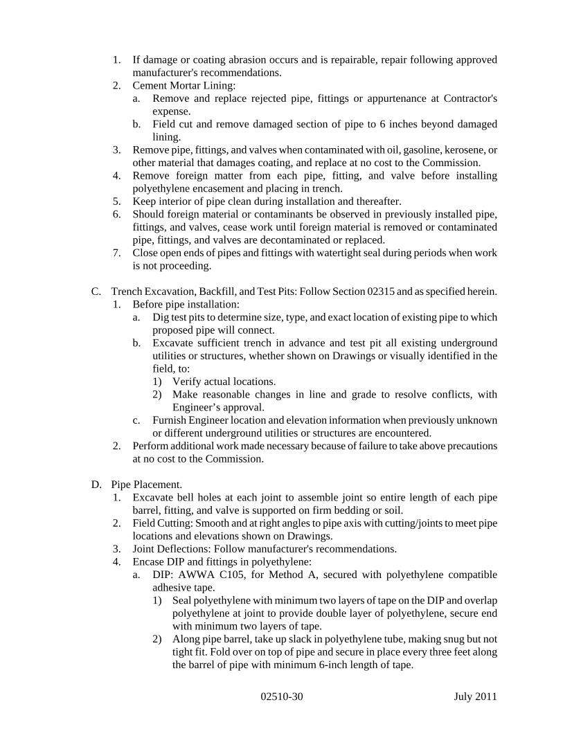
1. If damage or coating abrasion occurs and is repairable, repair following approved manufacturer's recommendations.
2. Cement Mortar Lining: a. Remove and replace rejected pipe, fittings or appurtenance at Contractor's
expense. b. Field cut and remove damaged section of pipe to 6 inches beyond damaged
lining. 3. Remove pipe, fittings, and valves when contaminated with oil, gasoline, kerosene, or
other material that damages coating, and replace at no cost to the Commission. 4. Remove foreign matter from each pipe, fitting, and valve before installing
polyethylene encasement and placing in trench. 5. Keep interior of pipe clean during installation and thereafter. 6. Should foreign material or contaminants be observed in previously installed pipe,
fittings, and valves, cease work until foreign material is removed or contaminated pipe, fittings, and valves are decontaminated or replaced.
7. Close open ends of pipes and fittings with watertight seal during periods when work is not proceeding.
C. Trench Excavation, Backfill, and Test Pits: Follow Section 02315 and as specified herein.
1. Before pipe installation: a. Dig test pits to determine size, type, and exact location of existing pipe to which
proposed pipe will connect. b. Excavate sufficient trench in advance and test pit all existing underground
utilities or structures, whether shown on Drawings or visually identified in the field, to: 1) Verify actual locations. 2) Make reasonable changes in line and grade to resolve conflicts, with
Engineer’s approval. c. Furnish Engineer location and elevation information when previously unknown
or different underground utilities or structures are encountered. 2. Perform additional work made necessary because of failure to take above precautions
at no cost to the Commission. D. Pipe Placement.
1. Excavate bell holes at each joint to assemble joint so entire length of each pipe barrel, fitting, and valve is supported on firm bedding or soil.
2. Field Cutting: Smooth and at right angles to pipe axis with cutting/joints to meet pipe locations and elevations shown on Drawings.
3. Joint Deflections: Follow manufacturer's recommendations. 4. Encase DIP and fittings in polyethylene:
a. DIP: AWWA C105, for Method A, secured with polyethylene compatible adhesive tape. 1) Seal polyethylene with minimum two layers of tape on the DIP and overlap
polyethylene at joint to provide double layer of polyethylene, secure end with minimum two layers of tape.
2) Along pipe barrel, take up slack in polyethylene tube, making snug but not tight fit. Fold over on top of pipe and secure in place every three feet along the barrel of pipe with minimum 6-inch length of tape.
July 2011 02510-30

In wet trench area, secure in place every two feet along barrel of pipe with minimum one layer of tape around the pipe.
3) For odd-shaped appurtenances, use flat sheet polyethylene: AWWA C105, Section 4.4.4, secure ends with minimum two layers of tape.
b. PVC pipe: Encase ductile iron fittings and valves in polyethylene as specified herein. Overlap polyethylene onto PVC pipe minimum 6 inches.
c. Fire hydrant lead pipe: Use DIP and fittings and encase in polyethylene following Standard Details.
5. Before backfilling, inspect polyethylene for rips, punctures and other damage and repair following AWWA C105.
6. Do not deflect PVC pipe at connection to DIP or fittings. 7. PVC AWWA C900 and C905 Pressure Pipe:
a. Make changes in horizontal, vertical, and curved alignment shown on Drawings by using fittings, high-deflection coupling, or joint deflections in the amount permissible by manufacturer's recommendations.
b. Use short lengths of pipe as necessary to accomplish curvature without exceeding individual allowable joint deflections specified by manufacturer.
c. Do not bend pipe. d. Tracer Wires for PVC Pipe:
1) Tape wire to top of pipe using PVC tape every 4 feet along the pipe, and on each side of each fitting. a) Tape: Minimum 2 inches wide and wrapping full circumference of
pipe. 2) Where required, splice with direct-bury wire connector, wire nut, or splice
kit and install as recommended by manufacturer. Protect and secure splice to pipe specified above.
3) Terminate tracer wire following Standard Details. E. Restrained Joints and Buttresses.
1. General: Make provisions for counteracting expected thrust due to static and dynamic forces including surge at bends, tees, reducers, valves, fire hydrants, and dead-ends whether or not shown on Drawings.
2. Restrained Joints: Provide following Drawings and Standard Details. a. Mark restrained joints at crown with 2 foot long by 4 inch wide orange paint
stripe perpendicular to and centered on joint. b. If testing pipeline for own convenience before backfilling is complete, provide
adequate temporary blocking at no cost to the Commission. c. Install restrained joints on pipe following Standard Details and manufacturer’s
recommended installation procedures. 1) Place "RESTRAINED JOINT PIPE" tape directly on top of pipe with
restrained joints before backfill operations have reached top of pipe. a) PVC Water Main: Place “Restrained Joint Pipe” tape under tracer wire. b) Secure "RESTRAINED JOINT PIPE" tape to top of pipe every 4 feet
along the pipe, and on each side of each fitting, wrapping full circumference of pipe.
2) Continue backfill operations following specifications and avoid displacement of warning tape.
d. Apply field coating wherever restraining device installation results in bare metal
July 2011 02510-31

3. Buttresses and Anchors: See Drawings and Standard Details. Engineer may inspect and approve excavations before buttresses and anchors are placed. a. Entire face of excavation against which buttresses will bear: Firm bearing, flat
and at proper angle to pipeline and reaction force. b. Wood form both sides of buttress and maintain dimensions following Standard
Details. Protect mechanical joint bolts from concrete.
3.3 JOINTS A. Mechanical Joints.
1. Before assembling joint, clean both bell and plain end of rust and foreign matter. 2. Assemble joint following AWWA C111, C600, C605 and specified herein. 3. For pipe plain ends to be inserted into mechanical joint bells, square cut and bevel
end. a. Clean and lubricate joint surfaces. b. Place gland on plain end followed by gasket and insert pipe into bell. c. Press gasket firmly and evenly into bell recess to center plain end in bell. d. Keep joint straight during assembly. e. Make deflection after joint assembly but before tightening bolts.
1) Do not deflect PVC pipe at connection to ductile iron or cast iron pipe or fittings.
f. Complete joint by alternate tightening of bolts with torque wrench set between: 1) 45-60 foot/pounds for 3 inch diameter. 2) 75-90 foot/pounds for 4 inch through 24 inch diameter. 3) 100-120 foot/pounds for 30 inch and 36 inch diameter. 4) 120-150 foot/pounds for 42 inch and 48 inch diameter.
g. Tighten bolts so gland and face of bell have approximately same distance between them at all times.
4. Where satisfactory sealing of joint is not attained at maximum permissible torque, disassemble, reclean, and reassemble joint with new gasket.
5. Coat uncoated metal components following FIELD APPLIED COATING OF EXPOSED FERROUS METAL specified herein.
B. Push on Joints.
1. File or grind bevel on plain end of field cut pipe lengths to resemble pipe as manufactured so plain end will slip into bell without hindrance or gasket damage. a. Place identifying mark on pipe that is not furnished with depth mark on plain
end to show depth of bell and to verify that pipe is fully set in bell. 2. Assemble joints following AWWA C600, AWWA C605 and specified herein.
a. Clean inside of bell and outside of plain end to obtain clean, smooth surfaces free of foreign matter.
b. Insert gasket in bell. c. Do not damage rubber to metal bond on restrained gaskets. d. Apply thin film of gasket lubricant furnished by joint manufacturer to inside
surface of gasket and to outside surface of plain end. e. Push plain end into bell.
July 2011 02510-32

f. Keep joint straight while pushing. g. Complete joint by forcing spigot into bell up to depth mark on spigot, using
equipment designed for purpose. h. DIP: Make deflection after joint is completely home.
1) Do not deflect PVC pipe at connection to ductile iron or cast iron pipe or fittings.
i. Assembly of PVC plain end into bell: Follow PVC pipe manufacturer’s recommendations.
j. Install restrained joints following manufacturer's recommendations. 3. Assemble proprietary restrained joint pipe and fittings following "Assemble Joints"
specified above and with modifications below. a. Fully extend assembled joints. b. Protect exposed nuts, bolts and exposed ferrous metals following FIELD
APPLIED COATING OF EXPOSED FERROUS METAL specified herein. c. Make connections to field cut restrained pipe with restrained push on joint kits
or mechanical joint solid sleeves restrained with wedge action restrainer glands specified herein.
d. No field welding of retainer rings. 4. Coat uncoated metal components following FIELD APPLIED COATING OF
EXPOSED FERROUS METAL specified herein below. C. Flanged Joints.
1. Remove grease from flange surface using solvent-soaked rag and wipe clean of dirt and grit.
2. Align flanges accurately, using spirit level, and pipe properly supported before gasket and bolts are inserted. a. Carefully place rubber gasket to ensure full flow and proper sealing of joint. b. Give bolt threads light coat of thread lubricant and then insert and turn nuts by
hand. c. Pull up bolts with wrench, employing crossover method. d. Bolt lengths and required torque: Follow manufacturer's requirements.
3. Coat uncoated metal components following FIELD APPLIED COATING OF EXPOSED FERROUS METAL specified herein below.
D. Mechanical Couplings.
1. Assemble mechanical coupling joint by placing coupling pieces on pipe ends and then place pipe ends together. a. Do not exceed tolerance between pipe ends of 1/2 inch. b. If tolerance is more than 1/2 inch, provide pipe spacer with 1/2 inch tolerance. c. Do not exceed coupling manufacturer's recommendations for spacer size for leak
proof joint assembly. d. Slide middle ring so it is centered at pipe ends juncture. e. Place gaskets and follower rings in place and bolt up. f. Tighten bolts to torque recommended by manufacturer.
2. Coat uncoated metal components following FIELD APPLIED COATING OF EXPOSED FERROUS METAL specified herein.
E. Solid Sleeves.
July 2011 02510-33
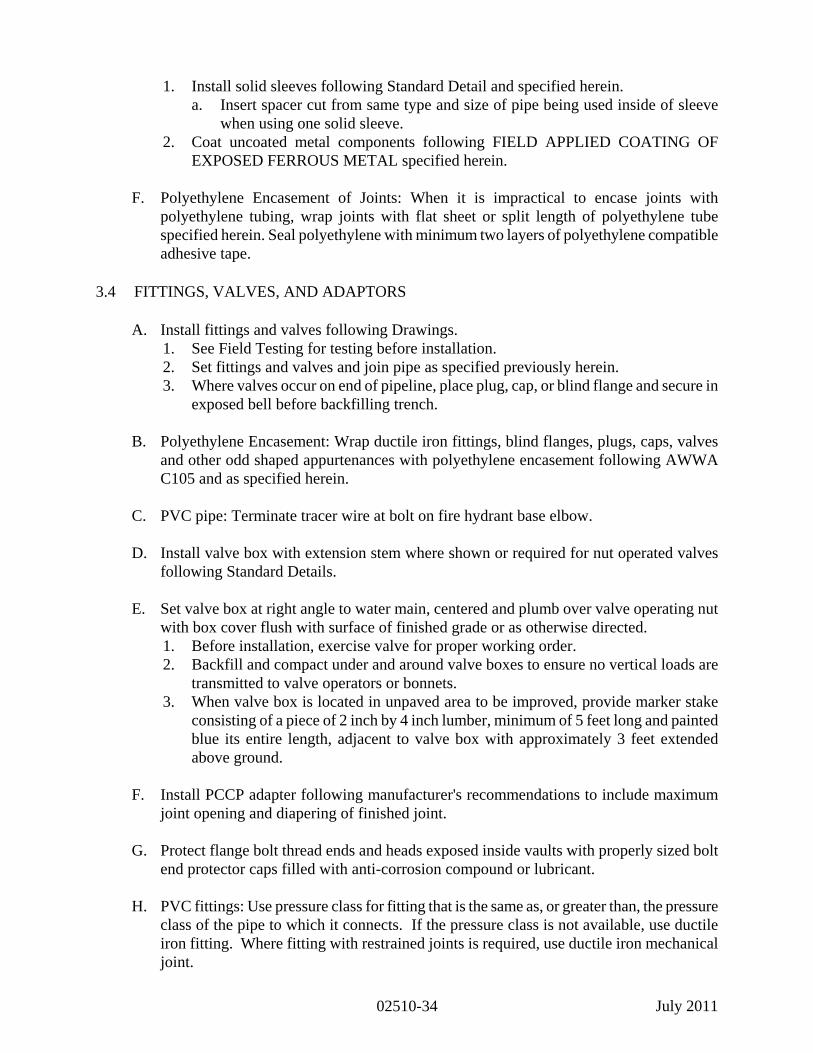
1. Install solid sleeves following Standard Detail and specified herein. a. Insert spacer cut from same type and size of pipe being used inside of sleeve
when using one solid sleeve. 2. Coat uncoated metal components following FIELD APPLIED COATING OF
EXPOSED FERROUS METAL specified herein. F. Polyethylene Encasement of Joints: When it is impractical to encase joints with
polyethylene tubing, wrap joints with flat sheet or split length of polyethylene tube specified herein. Seal polyethylene with minimum two layers of polyethylene compatible adhesive tape.
3.4 FITTINGS, VALVES, AND ADAPTORS
A. Install fittings and valves following Drawings.
1. See Field Testing for testing before installation. 2. Set fittings and valves and join pipe as specified previously herein. 3. Where valves occur on end of pipeline, place plug, cap, or blind flange and secure in
exposed bell before backfilling trench. B. Polyethylene Encasement: Wrap ductile iron fittings, blind flanges, plugs, caps, valves
and other odd shaped appurtenances with polyethylene encasement following AWWA C105 and as specified herein.
C. PVC pipe: Terminate tracer wire at bolt on fire hydrant base elbow. D. Install valve box with extension stem where shown or required for nut operated valves
following Standard Details. E. Set valve box at right angle to water main, centered and plumb over valve operating nut
with box cover flush with surface of finished grade or as otherwise directed. 1. Before installation, exercise valve for proper working order. 2. Backfill and compact under and around valve boxes to ensure no vertical loads are
transmitted to valve operators or bonnets. 3. When valve box is located in unpaved area to be improved, provide marker stake
consisting of a piece of 2 inch by 4 inch lumber, minimum of 5 feet long and painted blue its entire length, adjacent to valve box with approximately 3 feet extended above ground.
F. Install PCCP adapter following manufacturer's recommendations to include maximum
joint opening and diapering of finished joint. G. Protect flange bolt thread ends and heads exposed inside vaults with properly sized bolt
end protector caps filled with anti-corrosion compound or lubricant.
H. PVC fittings: Use pressure class for fitting that is the same as, or greater than, the pressure class of the pipe to which it connects. If the pressure class is not available, use ductile iron fitting. Where fitting with restrained joints is required, use ductile iron mechanical joint.
July 2011 02510-34

3.5 FIRE HYDRANTS
A. Install fire hydrants where indicated on Drawings following Standard Details. Place
streamer outlet perpendicular to street.
B. Install fire hydrant lead connection level, unless shown otherwise on Drawings.
C. Replacing Existing Fire Hydrant to Existing Main: Follow Drawings, Standard Details and as specified herein. 1. Blow off hydrant to confirm water flow (attach diffuser unless connecting to sanitary
sewer). 2. Leave hydrant open and close lead valve. 3. Confirm fire hydrant flow has stopped. 4. Test pit on lead valve and tee only to confirm existence and condition of strapping. 5. Install or replace strapping as necessary from tee to valve. 6. Install new lead pipe and fire hydrant to existing tee, following Standard Details. 7. Remove and salvage valve and fire hydrant and deliver to Commission warehouse or
as noted on Drawings.
D. Poured Lead Joint Lead Valve and Fittings: 1. Before removing existing tee and valve, clean existing pipe and check pipe for:
a. Lead joint valve and fittings larger than 16 inches in diameter, check outside diameter and roundness to verify that new solid sleeve and pipe will be watertight, before removing existing pipe, valves and fittings.
b. Lead joint valve and fittings 16 inches and smaller in diameter, with outside diameter or roundness not suitable for watertight connection, abandon as directed by Engineer.
2. Do not cut existing pipe closer than 18 inches to joint bell unless joint bell will be removed.
3. Reconnect existing main with new tee and solid sleeve, and install new valve, lead pipe and fire hydrant to existing tee following Standard Details.
3.6 WATER SERVICE CONNECTIONS
A. Install water service connections from main water line to property lines at elevations
indicated on Drawings, Standard Details, or at Engineer’s direction. 1. When elevations are not shown, install water service connections with minimum
cover of 42 inches. 2. To make direct service taps, apply 2 to 3 layers of polyethylene compatible adhesive
tape completely around polyethylene encased pipe to cover area where tapping machine and chain will be mounted or minimum of 12 inches. Direct tap through the taped polyethylene encasement.
3. When connecting to existing polyethylene encased cast or ductile iron water main, wrap water service connection pipe 3 feet from main (including corporation stop and saddle) with polyethylene encasement following AWWA C105. Seal polyethylene with minimum 2 layers of tape.
July 2011 02510-35

4. When connecting to existing non-polyethylene encased cast or ductile iron water main, provide service insulator and field applied coating on: a. Exposed water main up to 3 feet both sides of the tap (including service saddle, if
used). b. Service connection from water main for distance of 3 feet (including service
insulator) following Standard Details and specified herein. 5. Use copper pipe bending tools. 6. Mark location of end of water service connection pipe at property line with piece of 2
inch by 4 inch lumber, painted blue its entire length, placed vertically from bottom of trench and extending 2 feet above grade.
7. For connections from PVC water pipe, install tracer wire along the top of the water service connection pipe. Follow Tracer Wires for PVC Pipe, specified herein and Standard Details
B. Perform tapping of water main and insertion of corporation stop by qualified personnel
having in their possession qualification card issued by the Commission for performance of this work. 1. When no source of water is available from existing mains, provide potable water.
a. Maintain 60 psi pressure during service connection tapping process. 2. Use wrenches with smooth jaws of proper size to install corporation stops and
connect pipes thereto. Do not use wrenches with jaws that will score brass or copper.
3. Maintain minimum of 18 inches between taps, minimum 18 inches clear from DIP bells and minimum 24 inches clear from PVC pipe bells.
4. Install service saddle when tapping 3 or 4 inch diameter water main and for taps larger than 1 inch diameter on 6 inch through 12 inch diameter water mains.
5. After installing saddle, field coat saddle, straps, and associated hardware following FIELD APPLIED COATING OF EXPOSED FERROUS METAL specified herein.
6. After making tap and completing service connection, blow off at curb stop, pressurize, check for leaks to curb stop, and leave corporation stop in open position.
7. Backfill excavated area around pipe following Section 02315 and Standard Details. 8. Do not dry tap ductile iron mains without Engineer’s approval.
a. If so approved, make tap as specified herein, including lubrication of stop during installation.
b. Keep trench open at tap until water main has been placed in service so tap can be inspected for leakage.
9. PVC Water Pipe: Use of Service-tee fittings or service couplings permitted. 10. Tapping of PVC Pipe: AWWA C605, pipe manufacturer's recommendations, and
specified herein.
C. Assemble compression joints for type K copper pipe according to manufacturer’s recommendations. 1. Prepare copper pipe for connection by cleaning, deburring and rounding. 2. When rounding, use copper pipe rounding tool as recommended by compression
manufacturer. 3. Insert pipe into connection until it is completely home, tighten nut until it stops
turning at end of its internal threads. 4. Pressure test connection prior to backfilling.
July 2011 02510-36

D. Install service connections with outside meters following Drawings, Standard Details and
as specified herein. 1. Mark location of the outside water meter with a piece of 2 inch by 4 inch lumber,
painted blue its entire length, placed vertically along side the setting from bottom of excavation and extending 2 feet above grade.
2. Locate lumber within one foot horizontally of setting. 3. Paint 4 inch high letters “WATER METER” in black on both sides of the lumber
above grade. E. Right of way service connections: Extend to right of way or property line, whichever is
closer to main. F. For service connections 3 inch and larger diameter, install bends as required.
G. Replacement of Service Connections.
1. Minimum size copper pipe to property line, or as directed by Engineer. a. 1 inch for any existing connections 1 inch or smaller in diameter. b. 1 1/2 inch for any existing connections of 1 1/4 and 1 1/2.
2. Utilize existing tap at water main unless otherwise directed by Engineer to: a. Abandon existing tap and retap main line water pipe, or b. Remove existing tap and plug hole.
3. Replace existing curb stop or meter setting. a. Use freeze coupling to cut off flow from existing water service connection.
Do not use crimping tools.
H. Area Service Connection Contracts Only. 1. Engineer will issue an average of 3 work orders per week for water service
connections, to be constructed in the order they are received, or as directed by Engineer.
2. Schedule work orders designated as health hazards to be substantially completed within 10 working days and other work orders to be completed within 20 working days of issuance.
3. Provide sufficient equipment and work forces to commence and complete each connection within prescribed timeframe.
4. When directed to mobilize to site designated as Emergency by Engineer start within 24 hours. a. Cost incurred by the Commission due to work orders not completed within
timeframe specified herein may be deducted from monies owed Contractor. b. Issuance of new work orders may be suspended until outstanding work orders
are completed. c. Complete cleanup, restabilization, and restoration as weather permits on each
service connection location before leaving site to commence work at another location. 1) Restore non-paved areas following Section 02920.
3.7 CHLORINATION
July 2011 02510-37

A. Chlorinate and dechlorinate following Section 02511 and specified herein. B. Install 1 inch or 2 inch diameter corporation stops and couplings in water mains for
chlorination as required. 1. Remove stops not used for services and replace with plug.
C. While the sample analysis is being performed, Contractor may pressurize main for
purpose of making taps for service connections, by installing temporary jumper with approved backflow preventer to isolate main. 1. Remove as soon as taps are completed.
D. Place mains in service when analysis is complete and approved by Engineer.
3.8 VAULTS AND MANHOLES A. Access Manhole: Set following Section 02420 and Standard Details. B. Valve Vaults and Manholes: See Drawings, applicable sections of specifications, and
Standard Details.
3.9 LINESTOP
A. Before ordering linestop tapping saddle assembly. 1. Clean existing pipe, make circumferential measurement of pipe and check for
roundness to verify sleeve will fit. 2. Repair any damage to existing pipe coating with suitable coating material to original
line of coating as directed by pipe manufacturer's technical representative at no additional expense before backfilling.
B. Installation of linestop.
1. Excavate around existing pipe so as not to disturb thrust blocking. 2. Clean existing pipe. 3. Check pipe outside diameter and roundness to verify assembly will fit. 4. Provide all materials and equipment, to perform installation of linestop. 5. Provide blocking/support following Drawings. 6. Approved Tapping Equipment Fabricator/Installer to install tapping saddle assembly
to pipe and to insert linestop into pipe for line isolation. 7. After linestop is no longer required, approved Tapping Equipment
Fabricator/Installer to remove linestop and install completion plug and blind flange.
3.10 CONNECTION TO EXISTING MAIN BY TAPPING ASSEMBLY OR SLEEVE A. Before ordering Tapping Assemblies or Tapping Sleeves for existing pipe larger than 12
inches: 1. Confirm existing pipe type, clean pipe, make circumferential measurement and check
for roundness of pipe to verify sleeve will fit.
July 2011 02510-38
2. Repair any damage to existing pipe coating with suitable coating material to original line of coating as directed by pipe manufacturer's technical representative at no additional expense before backfilling.
B. Tapping Assembly and Valve Procedure for PCCP.
1. Before placing assembly: a. Clean existing PCCP. b. Check pipe outside diameter and roundness to verify assembly will fit.
2. Install assembly and valve. 3. Keep center of assembly within middle third of standard nominal length of PCCP. 4. Air test or hydrostatically test assembly following manufacturer's instructions to
ensure watertightness in presence of Engineer before making tap. 5. Encase steel saddle and U-bolts in concrete following manufacturer’s
recommendations.
C. Tapping Sleeve and Valve Procedure for Gray Iron and DIP and PVC pipe. 1. Before Tapping Pipe:
a. Clean existing pipe and check pipe outside diameter and roundness to verify that sleeve will fit.
b. Install test plug on sleeve for field pressurization of sleeve, valve and tapping machine assembly.
c. Air test or hydrostatically test sleeve following manufacturer's instructions to ensure watertightness in presence of Engineer.
2. Install sleeve and valve. 3. Keep closest edge of sleeve minimum of 9 inches from face of existing joint bell for
ductile iron and gray iron pipe. 4. In addition to cast markings required in AWWA C110, cast or stencil with
waterproof paint, the class designation of connecting pipe (AB or CD). 5. PVC Pipe:
a. Use only cutting/tapping tools and machines made specifically for cutting AWWA C900 pipe.
b. Keep closest edge of sleeve minimum of 15 inches from face of existing joint bell.
c. Install tapping machine without damage, scarring, or distortion to pipe. d. Support tapping sleeve and valve so its weight is not carried by pipe. e. Before backfilling, fill void under sleeve with compacted granular material or
flowable fill. 6. After tapping sleeve installation is complete on existing gray iron or DIP, field coat
tapping sleeve following FIELD APPLIED COATING OF EXPOSED FERROUS METAL specified herein.
D. Approved Tapping Contractors.
1. All Counties Tapping & Testing Inc., 4-12 inch DI/CI. 2. Antron Tapping Service, Inc., 4-12 inch DI/CI/PCCP. 3. Hydra Stop, Inc., all sizes DI/CI/PCCP. 4. Hydro Tap Service, Inc., 4-16 inch DI/CI, all sizes PCCP, and linestops. 5. Owens & Dove, 4-16 inch DI/CI/PCCP. 6. Price Brothers, all sizes PCCP.
July 2011 02510-39

7. Quality Cut Tapping Service, 4-16 inch DI/CI/PCCP. 8. B. K. Utilities Tapping Service, 4-12 inch DI/CI. 9. TDW Services, Inc., all sizes DI/CI/PCCP. 10. Mega Tap, 1-12 inch DI/CI/PCCP. 11. Pro Tapping, Inc., 3/4-36 inch DI/CI/PCCP/Transite (asbestos cement). 12. Cherry Hill Construction, Inc., 1-24 inch, DI/ CI/ PCCP/ Transite (asbestos cement). 13. W. D. Fox Tapping and Welding, Inc., DI/CI/Transite (asbestos cement), and PCCP. 14. Penniman & Browne, Inc., 1/2-16 inch PCCP, PVC, DI, CI, RCP, and steel. 15. DHC Corporation, 4-12 inch DI/CI 16. Or equal.
3.11 INSTALLATION OF CASING PIPE IN OPEN CUT
A. Install casing pipe in open cut following Section 02315 and 02530, and specified herein.
3.12 CONNECTIONS TO EXISTING MAINS A. Certain information is shown on Drawings relative to existing pipe and other construction.
1. This information was transferred from existing records and is not guaranteed to be accurate.
B. Before pipe installation see Excavation under INSTALLATION OF WATER MAIN
previously specified herein. 1. Do not cut existing pipe closer than 18 inches to joint bell unless joint bell will be
removed. C. Shutdowns.
1. Mains smaller than 16 inches: Operate valves for shutdown. Mains 16 inches and larger: Commission will operate valves for shutdown. a. The Commission cannot warrant that mains will be dry and free from all
leakage. b. After bacteriological analysis is completed and approved by the Engineer,
provide written request to shut down main 3 working days prior to intent. c. When new PRV is added to system and/or pressure zone boundary changes are
required, provide written request to shut down main 5 working days prior to intent.
d. Intent to shut down mains between the hours of 4 p.m. and 7:30 a.m. and on Saturdays, Sundays, and holidays requires 5 working days written request.
e. Shutdowns will not occur without Engineer’s approval and in the presence of his/her designee.
2. Pump and dewater to make necessary connections to existing water mains. 3. Maintain safe working distance from unrestrained closed valve.
a. Safe working distance from closed, unrestrained valve chart
Pipe Diameter (Inches)
Length of Straight Pipe in Front of
Valve (Feet) 4 65
July 2011 02510-40

6 90 8 120 10 150 12 185 14 215 16 250 20 320 24 395 30 525 36 660
Length of straight pipe is the amount of buried straight pipe on dewatered side of closed, unrestrained valve to prevent the valve from moving. No bends, joint deflections, gaps between plain-end inside couplings, or tunnels are to be within the designated length of straight pipe.
4. Make connections with greatest possible speed. Working more than 8 hours, at nighttime, or on weekends, requires prior permission from Engineer.
5. Will not be scheduled or performed on day before, day of or day after the following days: a. New Years Day. b. Good Friday. c. Easter. d. Beginning of Passover. e. Memorial Day. f. Independence Day. g. Labor Day. h. Rosh Hashanah. i. Yom Kippur. j. Thanksgiving. k. Hanukkah. l. Christmas.
6. Provide excavation and backfill required for shutdowns. 7. Cooperate and coordinate with Commission forces. 8. Commission will notify consumers prior to shutdown.
D. When making connection to existing PCCP utilizing ductile iron to PCCP adapter,
Contractor may tack weld adapter to existing PCCP. 1. Repair damage to gasket or pipe adapter at no cost to the Commission.
E. When connecting to existing polyethylene encased pipe, overlap joint following AWWA
C105, Method A. 1. When connecting polyethylene encased pipe to non-encased pipe, overlap
polyethylene 3 feet onto non-encased pipe following AWWA C105. Seal polyethylene with minimum two layers of compatible adhesive tape.
3.13 FIELD APPLIED COATING OF EXPOSED FERROUS METAL AND PIPE
CONNECTIONS OF DISSIMILAR MATERIALS
July 2011 02510-41

A. Coat exposed ferrous metal surfaces of joints, couplings, and uncoated steel with primer
and tape coating system after installation. 1. Do not coat stainless steel or high strength low alloy steel nuts and bolts.
B. Surface Preparation: Clean surfaces of rust, scale, soil, mud, oil, grease, and other
contaminants by hand or power tool following SSPC-SP2 or SP3 and other appropriate means as recommended by coating manufacturer. 1. Remove excess moisture and provide surface dryness as recommended by coating
manufacturer.
C. Application: Apply primer in uniform manner to clean and dry surfaces following coating manufacturer's recommendations. 1. Fill complex and irregular surfaces with appropriate mastic or filler tape to eliminate
bridging; then apply tape/wrap to primed and filled surfaces following coating manufacturer's recommendations.
2. When coating restraining rods or strapping, apply tape wrap longitudinally, i.e., cigarette wrapped.
3. Where metal being coated enters concrete, overlap coating onto concrete by minimum of 2 inches after placement of concrete.
D. Inspection: After field coating of specified items, conduct visual inspection to verify
complete coverage has been accomplished. 1. Repair damaged or incompletely coated surfaces following coating manufacturer's
recommendations. 3.14 ABANDONMENT
A. Cap ends of mains as shown and place required concrete blocking to retain cap on water
main to remain in service. B. For abandonment of water mains, construct brick or 2500 psi concrete bulkhead 9 inches
thick, or install approved plug or cap at each location where pipe was cut or valve removed. 1. Instead of above, Contractor may fill severed abandoned pipe with flowable fill.
C. Where mains are to be abandoned and removed to a fitting or valve, cut and plug main at
fitting or valve. 1. When shown on Drawings remove fire hydrants and valves, including lead joint tees
when encountered; salvage and deliver removed fire hydrants and valves to the Commission Depot.
2. Pipe, fittings, and other appurtenances that are removed, but not required to be salvaged become property of Contractor. a. Remove and dispose of offsite.
D. Abandon service connections 2 inches and smaller in diameter by:
1. Closing the corporation stop and disconnect the copper. 2. Capping corporation stop.
July 2011 02510-42

3. Removal of curb box. 4. Removal of meter setting in its entirety or when relocating service connection
remove meter setting 1 foot below existing ground, crimp existing service near bottom of meter box, fill meter box with dirt and compact to existing grade.
E. Abandonment of service connections 3 inches and larger.
1. Removal of Existing Gate Valve. a. For mechanical joint gate valve and fittings, remove existing gate valve and
install mechanical joint plug to existing tee. b. For tapping sleeve and valve connections, remove existing gate valve from
existing tapping sleeve assembly. 1) Install blind flange to existing flange end of tapping sleeve assembly.
c. For lead joint valve and fittings, remove existing gate valve and existing tee. 1) Before removing existing tee and valve, clean existing pipe and check pipe
diameter and roundness to verify that solid sleeve will fit pipe before removing existing pipe, valves, and fittings.
2) Do not cut existing pipe closer than 18 inches to joint bell unless joint bell will be removed.
3) Reconnect existing main with new pipe and solid sleeve. 2. Plug or cap ends of existing service connection abandoned sections.
F. Remove valve vault top slab and lower vault walls to minimum depth of 2 feet below
finish grade. 1. Fill remainder of vault with lean mix concrete or flowable fill following Section
03300. G. Salvage frames and covers.
1. Reuse when approved. 2. Deliver surplus frames and covers to the Commission Depot.
3.15 FIELD TESTING
A. Before hydrostatic leak test and installation of double disc and resilient-seated gate valves.
1. Operate valves at site from fully closed to fully open and return to fully closed position.
2. Observe for proper movement of discs and gate, and smooth function of valve parts. 3. If required, correct until satisfactory performance is demonstrated.
B. Before installation, hydrostatically test double disc and resilient-seated gate valves 16
inch and larger diameter for leakage at site in orientation as when installed. 1. Vent air from valve before conducting test. 2. Double disc gate valves:
a. Apply hydrostatic test pressure equal to valve's rated working pressure between discs for 15 minutes. 1) Rated working pressure: 150 psi unless otherwise noted. 2) Leakage past disc not to exceed 1 ounce per hour per inch of nominal valve
size. 3) No leakage through metal, flanged joints, or stem seals.
July 2011 02510-43

b. Alternatively, provide bulkhead, tapped as necessary, on 1 side of closed valve. Perform hydrostatic leakage test, as described above, between bulkhead and disc. 1) Repeat test on other side of valve.
3. Resilient seated gate valves: a. Apply hydrostatic test pressure equal to valve’s rated working pressure with gate
in open position for 15 minutes. 1) Rated working pressure: 150 psi unless otherwise noted. 2) No leakage through metal, pressure-containing joints or stem seals.
b. Alternatively, provide bulkhead, tapped as necessary, on 1 side of closed valve. Perform hydrostatic leakage test, as described above. 1) Repeat test on other side of valve.
C. Hydrostatic tests for water pipes.
1. For pipe 16-inch and larger diameter, an internal visual inspection will be made by the Commission of entire test section before ends are closed for test. a. Coordinate and assist as required with internal visual inspection.
2. Close ends of test sections with caps or plugs properly blocked or restrained to withstand pressures to be imposed.
3. Do not use existing or new WSSC pipe or appurtenances for temporary restraint or support during test.
4. Do not use resilient seated gate valves in closed position as the pressure boundary of a test section when test pressure exceeds 250 psi.
5. Equip and conduct hydrostatic tests with pressures computed by the Commission and described herein. a. When pipe installation is ready for testing and approved backfill operations
completed, notify Engineer in writing 5 working days in advance of test. b. Perform chlorination simultaneously with hydrostatic test unless otherwise
approved by Engineer. c. Conduct preliminary test to ensure main is ready for final test. d. Provide pressure gage recorder capable of printing continuous record of pressure
test readings (by Dickson Pressure Recorders, Model Numbers PW457 or PR81000), and charts, for testing.
e. Water meter for testing: Furnished by the Commission. f. Protect and shelter testing equipment. g. Set up testing equipment following Standard Details, and conduct tests on pipe
following AWWA C600. 1) Pressure Test:
a) Hydraulic gradient following Drawings. b) Pressure (operation plus surge) to be induced at low point of test
section for pressure test is equal to elevation of hydraulic gradient minus low point elevation of water main section to be tested, multiplied by 0.433, plus surge pressure as shown below:
Diameter of Pipe Psi 3-inch to 10-inch 120 12-inch to 14-inch 110 16-inch to 18-inch 100
July 2011 02510-44

20-inch 90 24-inch 85 30-inch 80 36-inch 75 42-inch to 60-inch 70
c) Fill length of water main to be tested with water, expelling air and
subject it to pressure computed as described above. d) Maintain this pressure for minimum of 2 hours.
2) Leakage Test: a) Conduct leakage test consecutively with pressure test. b) For leakage test induce pressure at high point of test section that is
equal to elevation of high hydraulic gradient minus high point elevation of water main section to be tested, multiplied by 0.433, but never less than 100 psi.
c) Maintain this pressure for minimum of 8 hours. d) Calculate maximum allowable leakage for water main using formula:
200,133
PSDL
where: L = maximum allowable leakage, gallons/hour. S = length of pipe in test section, in feet. D = nominal diameter of tested pipe, in inches. P = average test pressure, pounds per square inch, which will be
computed by averaging test pressures at low point and pressure at high point above.
6. For Pipes 14 Inch and Smaller: Conduct 2 hour combination pressure/leakage test. a. For 14 inch and smaller diameter mains the Contractor has the option for 2 hour
test to substitute the recording gage with a Calibrated Needle Pressure Gage with zero leakage.
b. After installation of the water service connections, conduct a 2 hour pressure test at 125 psi, utilizing either option to conduct the test. 1) Not to be conducted on replacement and relocation projects without
Engineer’s direction.
D. Hydrostatically test thrust restraint system of double disc and resilient-seated gate valves, 16 inch and larger diameter, after valve installation and successful testing of water main. 1. Double disc gate valves:
a. Pressure test each side of closed valve for no less than 1 hour to same pressure used for water main pressure test, while other side is depressurized.
b. Dewatering of depressurized side is not necessary. c. Pressure not to exceed twice rated working pressure of valve. d. Repeat test on other side of valve. e. Repair leaks or damages to valve body, vault, piping, joints, fittings, or
appurtenances in vault at no cost to the Commission. f. Do not operate valve when water pressure is greater than valve's rated working
July 2011 02510-45

pressure. 2. Resilient-seated gate valves:
a. Pressure test each side of closed valve for no less than 1 hour to same pressure used for water main pressure test, while other side is depressurized.
b. Dewatering of depressurized side is not necessary. c. Pressure not to exceed 250 psi. d. Repeat test on other side of valve. e. Repair leaks or damages to valve body, vault, piping, joints, fittings, or
appurtenances in vault at no cost to the Commission. f. Do not operate valve when water pressure is greater than 250 psi.
E. Should test results show displacement, damage, or leakage in excess of allowable amount,
repair displacement, damage, and eliminate leakage. 1. Retest until specified conditions are met, to Engineer's requirement, at no cost to the
Commission. 2. Commission will observe test for each segment once without charge to Contractor.
a. Cost of further tests will be deducted from monies owed Contractor at prevailing hourly rates published by the Commission.
3. Additional water use resulting from failed water main test shall be metered in gallons with the Commission reimbursed for water use at the prevailing rates.
F. PVC Water Pipe Continuity Testing.
1. Test tracer wire for continuity, in presence of Engineer, after backfill is complete and before Substantial Completion.
2. Notify Engineer in writing 5 working days in advance to schedule testing. 3. Continuity test to consist of locating the PVC water pipe and water services with an
electronic-type pipe locator. 4. If test for continuity is negative, repair or replace as necessary to achieve continuity.
3.16 TEMPORARY BYPASS WATER SERVICE SYSTEM
A. Provide telephone and pager numbers to Engineer for designated after hours emergency work crew before installation of bypass system.
B. Remove no more than 5,000 feet of existing main from service at one time unless
Engineer approves otherwise. C. Before water main to be replaced or cleaned and lined is shut down, provide temporary
bypass piping system of adequate size to provide water service and fire protection to affected properties as required herein and as directed by the Engineer: 1. Notify Engineer:
a. At least 24 hours in advance for installation of temporary connections. b. When additional bypass services are made. c. When problems develop with any meters or services.
D. Use nearest available fire hydrant for connection to temporary bypass system.
1. Where fire hydrants cannot be used, excavate and tap existing water main at Engineer’s direction.
July 2011 02510-46

2. Provide backflow preventers on temporary bypass piping at connection to source. 3. Make temporary bypass service attachments to fire hydrants in a manner that will
allow removal with a minimum of effort in case of emergency. 4. Provide temporary fire hydrants as follows:
a. Single family residential area. 1) Spacing maximum 500 feet apart measured along an improved roadway and
within 400 feet from the most distant corner of any dwelling. b. Townhouses and garden apartments.
1) Spacing maximum 250 to 300 feet apart measured along an improved roadway and within 300 feet from the most distant corner of any building.
c. Commercial, industrial, high-rise, and elevator type apartments. 1) Spacing maximum 250 to 300 feet apart measured along an improved
roadway. 5. Provide temporary hydrants with markers that are clearly visible from street.
E. Provide temporary service connection to each property affected by required water main
shutdowns. 1. Connect temporary service by removing outside meter and making temporary
connection to existing service connection; connection to house hose bib; or at Engineer’s direction.
2. Provide a valved "Y" on house hose bibs when used for temporary service connection.
3. Provide Engineer 48 hours notice before removing meters. 4. Cap removed meters at both ends. 5. Place in clear plastic bags and hang inside meter pit to prevent damage, switching
and misplacement for pickup by Commission. 6. Protect meters and meter cover. 7. Use notched meter covers when temporary services are connected. 8. Where double meters exist, label meters with address. 9. Adjust meter housing or curb stop to existing grade. 10. Coordinate with Engineer for existing meter readings and in/out sheets. 11. Meters improperly installed will be removed and correctly installed by the
Commission. a. A cost of $500 per incident will be deducted from payment to Contractor.
F. Placement and protection of temporary bypass piping system.
1. Do not install between November 15 and March 1. 2. Do not place during freezing weather and if already installed, protect from freezing. 3. Provide cap and sampling connection at downstream end of each separate bypass
piping segment. a. Do not loop downstream end of segment back to or near inlet of segment.
4. Cover sections of temporary bypass lines that cross driveways or sidewalks and ramp with bituminous cold mix.
5. Protect concrete and brick driveways to prevent discoloration from bituminous material.
6. Place bypass lines at road crossings below the existing road surface. 7. Place sections of bypass or services that cross sidewalks with barricades, ramps, and
fluorescent paint.
July 2011 02510-47
8. Place crossings of bypass lines parallel and/or perpendicular to handicap ramps, below existing grade.
9. Install and support temporary bypass piping at storm drain inlet crossing so that piping and supports do not impede storm water from entering storm drain inlet.
G. House to house connections are prohibited.
H. Temporary bypass piping for existing service connections 3 inch and larger diameter and
temporary fire protection: Minimum 4 inch diameter.
I. Disinfect temporary bypass piping, including temporary house services, utilizing distribution system residual. 1. The Commission will take bacteriological samples within 3 working days after
receipt of written notification from Contractor that disinfection is complete. 2. Results of sample analysis will be available within 3 calendar days after sampling. 3. If samples are not approved, chlorinate and notify the Engineer to take new samples
for testing. 4. Cost of the additional disinfection, samples and testing: Contractor's expense. 5. After samples are approved by the Commission, place bypass piping in service.
J. If temporary bypass requires placement outside of Town Limits, acquire necessary
permits. K. Maintenance or repair of temporary bypass piping system.
1. Respond to Commission’s notification within 30 minutes and arrive at work site within 2 hours of notification.
2. Provide adequate equipment, materials, and labor to take remedial actions within 1 hour of arrival at site in order to restore temporary bypass system in a timely manner at no cost to the Commission.
3. Call radio room (301-206-4002) immediately after arriving at the work site and after work has been completed.
4. Failure to respond back to Commission within 30 minutes, failure to arrive at work site within 2 hours or failure to take remedial action within 1 hour of arrival on site: a. $500 fee per remedial action event and cost incurred by the Commission to
restore service assessed to Contractor.
PART 4 MEASUREMENT AND PAYMENT 4.1 PIPE
A. Measurement: By linear foot of various types and sizes measured horizontally along
centerline of pipe with no deductions made for lengths of fittings, connections, or valves, except: 1. Fire hydrant leads will be measured beginning at water main centerline to hydrant
centerline. B. Payment: At unit price for each linear foot for each size listed in Bid Schedule.
July 2011 02510-48
1. Payment includes test pits required by Contract Documents, excavation, bedding and backfill; installation of pipe, fittings, valves, valve boxes, branch connections, connections to new and existing mains, corporation stops, and couplings for chlorination.
4.2 SERVICE CONNECTIONS
A. Measurement: By linear foot of various types and sizes provided measured horizontally
along centerline of pipe from center of main to property line following Standard Details. 1. No deductions will be made for lengths of fittings, connections, or valves.
B. Payment: At unit price for each linear foot for each size listed in Bid Schedule.
1. Payment includes excavation, bedding and backfill; installation of pipe, fittings, curb stops, corporation stops, valves, valve boxes, and connections to new and existing mains.
4.3 SERVICE CONNECTION WITH OUTSIDE METER
A. Measurement: By linear foot of various types and sizes measured horizontally along
centerline of pipe from center of main to the limits following Drawings and Standard Details. 1. No deductions will be made for lengths of fittings, connections, or valves.
B. Payment: At unit price for each linear foot for each size listed in Bid Schedule.
1. Payment includes excavation, bedding and backfill; installation of pipe, fittings, valves, valve boxes, meter setting, meter, and connections to new and existing mains.
4.4 EXTEND AND RECONNECT EXISTING WATER SERVICE CONNECTIONS TO NEW MAIN A. Measurement: By linear foot measured horizontally along center line of pipe from
centerline of existing main to centerline of new main. 1. No deductions will be made for lengths of fittings, connections, or valves.
B. Payment: At unit price for each linear foot listed in Bid Schedule.
1. Payment includes excavation, bedding and backfill; installation of pipe, fittings, corporation stops, valves, valve boxes, reconnection to new main, and temporary water service.
4.5 RECONNECTION OF EXISTING WATER SERVICE CONNECTIONS
A. Measurement: By each complete in place. B. Payment: At unit price for each listed in Bid Schedule.
July 2011 02510-49
1. Payment includes excavation, bedding and backfill; installation of fittings, corporation stops, valves, valve boxes, reconnection to new main; and temporary water service.

4.6 REPLACEMENT OF SERVICE CONNECTIONS
A. Measurement: By linear foot of various types and sizes provided measured horizontally along centerline of pipe from center of main to property line following Standard Details. 1. No deductions will be made for lengths of fittings, connections, or valves.
B. Payment: At unit price for each linear foot listed in Bid Schedule.
1. Payment includes excavation, bedding and backfill; installation of pipe, fittings, corporation stops, valves, valve boxes, curb stops or meter setting and meter, as required; abandonment of existing service connection, connection to new and existing mains; and temporary water service.
4.7 FIRE HYDRANTS A. Measurement: By each complete in place, including connection to fire hydrant lead
following Standard Details. B. Payment: At unit price for each listed in Bid Schedule.
1. Payment includes excavation, bedding and backfill; incidental appurtenances and installation of fire hydrant.
2. Excludes fire hydrants installed on meter vault bypass piping.
4.8 STRUCTURES
A. Measurement: By each for valve manholes and vaults, blowoffs, and entry port manholes of various types and sizes provided complete, in place.
B. Payment: At unit price for each of various types and sizes as listed in Bid Schedule.
1. Payment includes excavation, bedding and backfill; installation of pipe, valves and fittings from main, provision of flanged pipe and fittings, manholes, vaults, other materials not furnished by the Commission and incidentals following Drawings and Standard Details.
2. Payment does not include mainline pipe, mainline valves or mainline fittings.
4.9 METER VAULTS A. Measurement: By each of various types and sizes provided complete in place, including
frame and cover. B. Payment: At unit price for each of various types and sizes listed in Bid Schedule.
1. Payment includes excavation, bedding and backfill, installation of pipe, fittings, fire hydrants, valves, and valve boxes that make up bypass and are within vault area between 2 bypass tees or taps, and incidentals following Standard Details.
4.10 PIPE IN TUNNELS OR CASINGS
July 2011 02510-50

July 2011 02510-51
A. Measurement: By linear foot measured horizontally along centerline of pipe. B. Payment: At unit price for each linear foot for each size listed in Bid Schedule.
1. Payment includes bulkheads casing spacers, incidental appurtenances and installation of pipe following Drawings and Standard Details.
4.11 CASING PIPE INSTALLED IN OPEN CUT
A. Measurement: By linear foot measured horizontally along centerline of pipe from
bulkhead to bulkhead. B. Payment: At unit price for each linear foot listed in Bid Schedule.
1. Payment includes excavation, bedding and backfill; casing pipe, and incidental appurtenances following Drawings and Standard Details.
4.12 OUTSIDE METER SETTING ONLY
A. Measurement: By each complete in place, at Engineer’s direction. B. Payment: At fixed contingent unit price or unit price for each of various types and sizes
listed in Bid Schedule. 1. Payment includes excavation, backfill and bedding, installation of meter setting,
housing, and appurtenances following Drawings and Standard Details and disposal of existing meter setting and housing.
4.13 MOBILIZATION: See Section 01110. 4.14 ABANDONMENT OF SERVICE CONNECTIONS
A. Measurement: By each of various types and sizes abandoned in separate trench from new or renewed service, complete in place.
B. Payment: At unit price or contingent unit price for various types and sizes listed in Bid
Schedule. 1. Payment includes excavation, abandonment of existing service connection, and
backfill.
**WSSC**