specifications valu-beam sensors - banner...
TRANSCRIPT

Product
Line SpecificationsVALU-BEAM ® Sensors
Rugged, self-contained photoelectric sensors for industrial applications
Printed in USA P/N 32894
•
•
•
•
•
•
Economy, performance, and durability in a family of rugged,self-contained sensors for demanding industrial applications
912 Series sensors have solid-state outputs; models for either10-30V dc or 24-250V ac operation (pages 4 to 9)
915 Series sensors have electromechanical relay output; modelsfor 12-28V ac/dc, 90-130V ac, or 210-250V ac (pages 10 to 13)
990 Series sensors output to a built-in 6-digit totalizing counter;operate from both 12-115V dc and 10-250V ac (pages 14 to 17)
Many models available in opposed, retroreflective, diffuse,convergent beam, and fiber optic sensing modes
Highly-visible top-mounted LED output indicator; 912 Seriessensors have Banner's exclusive, patented AID™ indicator system

WARRANTY: Banner Engineering Corporation warrants its products to be free from defects for one year. Banner Engineering Corporation will repair or replace,free of charge, any product of its manufacture found to be defective at the time it is returned to the factory during the warranty period. This warranty does notcover damage or liability for the improper application of Banner products. This warranty is in lieu of any other warranty either expressed or implied.
2
VALU-BEAMs are a family of rugged, self-contained photoelec-tric sensors designed for especially demanding industrial applica-tions where economy, performance, and durability are important.VALU-BEAMs are built in a variety of operating voltages (both dcand ac) and output types (solid state and electromechanical relay).SM912 and SM2A912 Series VALU-BEAMs have solid stateoutputs and are available in either 10-30V dc-powered or 24-250Vac-powered models (see specifications, page 4). SMW915,SMA915, and SMB915 Series VALU-BEAMs have electrome-chanical relay output and operate from 12-28V ac/dc, 90-130V ac,or 210 to 250V ac respectively. SMA990 Series VALU-BEAMshave a built-in 6-digit totalizing counter and operate on 12 to 115Vdc or 10 to 250V ac. A fourth VALU-BEAM line, SMI912 Seriesintrinsically safe sensors (low voltage dc sensors having FactoryMutual approval for use with intrinsic-safe barriers in hazardousareas) is covered in data sheet P/N 03396 and the Banner catalog.
Powerful, modulated LED light sources give VALU-BEAM sen-sors greater sensing range than competitive units and a high degreeof immunity to ambient light. All models are totally epoxy-encapsulated and housed in molded VALOX® housings for theultimate in shock, vibration, moisture, and corrosion resistance.All VALU-BEAM sensors conform to NEMA standards 1, 2, 3,3S, 4, 4X, 12, and 13.
VALU-BEAM sensors may be mounted from either the front or therear using their two through-mounting holes, or by the outside
threads of their M30x1.5 threaded base (mounting nut supplied),making them ideal for conveyor and other production line applica-tions. A versatile 2-axis steel accessory mounting bracket (modelSMB900) simplifies mounting and alignment. Model SMB30SMswivel-mount bracket offers the ultimate in flexibility and conve-nience. The bases of standard VALU-BEAMs have a 1/2" NPSintegral internal conduit thread, and are supplied with a 6-footPVC-covered cable. Models with a NEMA-4 rated quick-discon-nect connector (QD models) are available optionally.
All VALU-BEAM sensors have an easily-visible top-mounted redLED indicator to assist in alignment and system monitoring. OnSMA915, SMB915, SMW915, and SMA990 Series VALU-BEAMs, this indicator lights whenever the sensor "sees" itsmodulated light source. On SM2A912 Series 2-wire sensors, theLED lights whenever the load is energized. SM912 Series sensorshave Banner's exclusive, patented "AID" system (Alignment Indi-cating Device, US patent #4356393) which lights the indicatorLED whenever the sensor "sees" its modulated light source, andalso pulses the LED at a rate proportional to the received light signalstrength. This feature greatly simplifies alignment: in most situa-tions, alignment becomes simply a matter of positioning the sensorfor maximum LED pulse rate.
VALU-BEAMs offer a choice of light or dark operate in the samesensor. This is done via a rear panel control or, in the relay outputunits, by offering both N/O and N/C output relay contacts.
!WARNING VALU-BEAM photoelectric presence sensors do NOT include the self-checking redundant circuitry necessaryto allow their use in personnel safety applications. A sensor failure or malfunction can result in either an energized or a de-energizedsensor output condition.
Never use these products as sensing devices for personnel protection. Their use as safety devices may create an unsafe condition whichcould lead to serious injury or death.
Only MACHINE-GUARD and PERIMETER-GUARD Systems, and other systems so designated, are designed to meet OSHA andANSI machine safety standards for point-of-operation guarding devices. No other Banner sensors or controls are designed to meet these standards, andthey must NOT be used as sensing devices for personnel protection.
VALU-BEAM ® Sensors

Series Model Sensing Mode Range Operating Voltage* Page
912 Series SMA91E & SM91R Opposed: long range 200 feet 10 to 30V dc* p. 5SMA91E & SM2A91R Opposed: long range 200 feet 24 to 250V ac* p. 5SMA91ESR & SM91RSR Opposed: short range 10 feet 10 to 30V dc* p. 5SMA91ESR & SM2A91RSR Opposed: short range 10 feet 24 to 250V ac* p. 5
SM912LV Retroreflective: visible beam 30 feet 10 to 30V dc p. 5SM2A912LV Retroreflective: visible beam 30 feet 24 to 250V ac p. 5SM912LVAG Retroreflective: polarized beam 15 feet 10 to 30V dc p. 5SM2A912LVAG Retroreflective: polarized beam 15 feet 24 to 250V ac p. 5
SM912D Diffuse (proximity): long range 30 inches 10 to 30V dc p. 6SM2A912D Diffuse (proximity): long range 30 inches 24 to 250V ac p. 6SM912DSR Diffuse (proximity): short range 15 inches 10 to 30V dc p. 6SM2A912DSR Diffuse (proximity): short range 15 inches 24 to 250V ac p. 6
VALU-BEAM Sensors
All 990 Seriessensors operatefrom 10 to 250V acor 12 to 115V dc
Sensors withSPDTelectromechanicaloutput relay
Sensors withbuilt-in 6-digittotalizing counter
SM912CV Convergent beam: visible red 1.5-inch focus 10 to 30V dc p. 6SM2A912CV Convergent beam: visible red 1.5-inch focus 24 to 250V ac p. 6SM912C Convergent beam: infrared 1.5-inch focus 10 to 30V dc p. 7SM2A912C Convergent beam: infrared 1.5-inch focus 24 to 250V ac p. 7
SMA91EF & SM91RF Opposed fiber optic: glass fibers see specs 10 to 30V dc* p. 6SMA91EF & SM2A91RF Opposed fiber optic: glass fibers see specs 24 to 250V ac* p. 6
SM912F Fiber optic: glass fibers see specs 10 to 30V dc p. 7SM2A912F Fiber optic: glass fibers see specs 24 to 250V ac p. 7
915 Series SMA91E & SMW95R Opposed: long range 200 feet 12 to 28V ac/dc* p. 11SMA91E & SMA95R Opposed; long range 200 feet 90 to 130V ac* p. 11SMA91E & SMB95R Opposed: long range 200 feet 210 to 250V ac* p. 11SMA91ESR & SMW95RSR Opposed: short range 10 feet 12 to 28V ac/dc* p. 11SMA91ESR & SMA95RSR Opposed: short range 10 feet 90 to 130V ac* p. 11SMA91ESR & SMB95RSR Opposed: short range 10 feet 210 to 250V ac* p. 11
SMW915LV Retroreflective: visible beam 30 feet 12 to 28V ac/dc p. 11SMA915LV Retroreflective: visible beam 30 feet 90 to 130V ac p. 11SMB915LV Retroreflective: visible beam 30 feet 210 to 250V ac p. 11SMW915LVAG Retroreflective: polarized beam 15 feet 12 to 28V ac/dc p. 11SMA915LVAG Retroreflective: polarized beam 15 feet 90 to 130V ac p. 11SMB915LVAG Retroreflective: polarized beam 15 feet 210 to 250V ac p. 11
SMW915D Diffuse (proximity): long range 30 inches 12 to 28V ac/dc p. 12SMA915D Diffuse (proximity): long range 30 inches 90 to 130V ac p. 12SMB915D Diffuse (proximity): long range 30 inches 210 to 250V ac p. 12SMW915DSR Diffuse (proximity): short range 15 inches 12 to 28V ac/dc p. 12SMA915DSR Diffuse (proximity): short range 15 inches 90 to 130V ac p. 12SMB915DSR Diffuse (proximity): short range 15 inches 210 to 250V ac p. 12
SMW915CV Convergent: visible red 1.5-inch focus 12 to 28V ac/dc p. 12SMA915CV Convergent: visible red 1.5-inch focus 90 to 130V ac p. 12SMB915CV Convergent: visible red 1.5-inch focus 210 to 250V ac p. 12
SMW915F Fiber optic: glass fibers see specs 12 to 28V ac/dc p. 13SMA915F Fiber optic: glass fibers see specs 90 to 130V ac p. 13SMB915F Fiber optic: glass fibers see specs 210 to 250V ac p. 13
SMW915FP Fiber optic: plastic fibers see specs 12 to 28V ac/dc p. 13SMA915FP Fiber optic: plastic fibers see specs 90 to 130V ac p. 13SMB915FP Fiber optic: plastic fibers see specs 210 to 250V ac p. 13
990 Series SMA91E & SMA99R Opposed: long range 200 feet* p. 15SMA91ESR & SMA99RSR Opposed: narrow beam 10 feet* p. 15
SMA990LV Retroreflective: visible beam 30 feet p. 15SMA990LVAG Retroreflective: polarized beam 15 feet p. 15SMA990LT Retroreflective: infrared beam 30 feet p. 16
(used for "people counting")
SMA990CV Convergent beam: visible red 1.5-inch focus p. 16
SMA990F Fiber optic: glass fibers see specs p. 17SMA990FP Fiber optic: plastic fibers see specs p. 16
Sensors withinfinite-lifesolid-state outputrelay
*NOTE: Emitter voltage range is 10-250V ac or dc
3

dc sensor specifications ac sensor specifications
Dimension Drawing,Front View
VALU-BEAM 912 Series Sensors
4
Rear View
Functional Schematic: SM912 Series DC Sensors Functional Schematic: SM2A912 Series AC Sensors
SUPPLY VOLTAGE: 24 to 250V ac (50/60Hz), except for SMA91E,ESR, and EF emitters, which operate from 10 to 250V ac or dc.
OUTPUT CONFIGURATION: solid-state switching element.
OUTPUT RATING: min. load current 10mA; max. steady-state loadcapability 750mA to 50°C ambient (122°F), 500mA to 70°C ambient(158°F). Inrush capability 4 amps for 1 sec. (non-repetitive). Off-stateleakage current less than 1.7mA rms. On-state voltage drop ≤5 voltsrms at 750mA load, ≤10 volts rms at 15mA load.
OUTPUT PROTECTION: protected against false pulse on power-up and inductive load transients.
RESPONSE TIME: 8 milliseconds ON, 8 milliseconds OFF (exceptreceiver-only units, which are 8 ms ON and 4 ms OFF). OFF time doesnot include load response of up to 1/2 ac cycle (8.3 milliseconds).Independent of signal strength. Response time specification of the loadshould be considered when important. 300-millisecond delay onpower-up (outputs are non-conducting during this time).
REPEATABILITY OF RESPONSE: see individual sensor specs.Does not take into consideration "off" response time variation of up to1/2 ac cycle (8.3ms) and load response time. Independent of signalstrength.
CONSTRUCTION: reinforced VALOX® housing, totally encapsu-lated, molded acrylic lenses, stainless steel hardware. Meets NEMAstandards 1, 2, 3, 3S, 4, 4X, 12, and 13.
CABLE: 6' of PVC-jacketed 2-conductor cable standard. Three-pinquick-disconnect (QD) models are available optionally (one connectorpin goes unused). Model MBCC-312 3-conductor cable for "QD"models must be purchased separately (see pages 18 and 19).
ADJUSTMENTS: LIGHT/DARK OPERATE select switch andSENSITIVITY control potentiometer, both located on rear of sensor.
INDICATOR LED: top-mounted red LED indicator lights whenoutput is conducting. Model SMA91E emitter has a visible-red "tracerbeam" which indicates "power on" and enables easy "line-of-sight"alignment.
OPERATING TEMPERATURE RANGE: -20 to +70 degrees C(-4 to +158 degrees F).
SUPPLY VOLTAGE: 10 to 30V dc at 20mA, exclusive of load(except for SMA91E, ESR, and EF emitters, which operate from 10 to250V ac or dc, 10mA max.).
OUTPUT CONFIGURATION: one current sourcing (PNP) and onecurrent sinking (NPN) open-collector transistor.
OUTPUT RATING: 250mA continuous, each output. Off-stateleakage current less than 10 microamps. Output saturation voltage:for PNP output, <1 volt at 10mA and <2 volts at 250mA; for NPNoutput, <200 millivolts at 10mA and <1volt at 250mA.
OUTPUT PROTECTION: protected against false pulse on power-up, inductive load transients, power supply polarity reversal, andcontinuous overload or short circuit of outputs.
RESPONSE TIME: 4 milliseconds ON, 4 milliseconds OFF (exceptreciever-only units, which are 8 ms ON and 4 ms OFF). Independentof signal strength. 100 millisecond delay on power-up (outputs non-conducting during this time).
REPEATABILITY OF RESPONSE: see individual sensor specs.Independent of signal strength.
CONSTRUCTION: reinforced VALOX® housing, totally encapsu-lated, molded acrylic lenses, stainless steel hardware. Meets NEMAstandards 1, 2, 3, 3S, 4, 4X, 12, and 13.
CABLE: 6' of PVC-jacketed cable standard; 2-conductor (emitters) or4-conductor. Quick-disconnect (QD) models are available optionally.Model MBCC-412 4-conductor cable for dc "QD" models must bepurchased separately. DC "QD" emitters use cable model MBCC-312."QD" cable is purchased separately; see pages 18 and 19.
ADJUSTMENTS: LIGHT/DARK OPERATE select switch andSENSITIVITY control potentiometer, both located on rear of sensor.
INDICATOR LED: exclusive, patented Alignment Indicating De-vice system (AID™, US patent #4356393) lights a top-mounted redLED indicator whenever the sensor sees a "light" condition, with asuperimposed pulse rate proportional to the light signal strength (thestronger the signal, the faster the pulse rate).
OPERATING TEMPERATURE RANGE: -20 to +70 degrees C(-4 to +158 degrees F).

SMA91E &SM2A91RVoltage: 24 to 250V ac,("E": 10-250V ac/dc)Range: 200 feet (60 m)Response: 8ms on/4 offBeam: infrared, 880nmEffective beam: 0.5" dia.
RETROREFLECTIVE
OPPOSED Mode
A visible-red light beam reduces the potential for false signals from highlyreflective objects ("proxing") and simplifies alignment. AG (anti-glare) modelspolarize the emitted light and filter out unwanted reflections, making their usepossible in applications otherwise unsuited to retroreflective sensing (whenreduced excess gain is acceptable). Maximum range with "LV" units is attainedwhen using the model BRT-3 3" corner cube reflector. For details on retroreflec-tive target materials, see the Banner product catalog.
Excess GainModels
SM912LVAG(anti-glare filter)Voltage: 10 to 30V dcRange: 1 to 15 feet (4,5 m)Response: 4ms on/offBeam: visible red, 650nm(with polarizing filter)
SM2A912LVAG(anti-glare filter)Voltage: 24 to 250V acRange: 1 to 15 feet (4,5 m)Response: 8ms on/offBeam: visible red, 650nm(with polarizing filter)
SM912LVVoltage: 10 to 30V dcRange: 6 inches to 30 feet (9 m)Response: 4ms on/offBeam: visible red, 650nm
SM2A912LVVoltage: 24 to 250V acRange: 6 inches to 30 feet (9 m)Response: 8ms on/offBeam: visible red, 650nm
Beam PatternSensing Mode
Opposed mode sensors have higher excess gain than other models, andtherefore should be used whenever possible. The small size of thesesensors makes them ideal for many conveyor applications, and their smalleffective beam size (particularly of the ESR/RSR models) enables themto reliably detect relatively small objects. VALU-BEAM opposed modesensors have a visible red "tracer beam" which greatly simplifies sensoralignment. ESR/RSR models have a wide beam angle for very forgivingalignment within the 10 foot range. E/R models have a narrow beamspread and should be used when it is important to minimize optical"crosstalk" between adjacent emitter-receiver pairs at close range inmultiple sensor arrays.
SMA91E & SM91RVoltage: 10 to 30V dc,("E": 10-250V ac/dc)Range: 200 feet (60 m)Response: 8ms on/4 offBeam: infrared, 880nm;visible red tracer beamEffective beam: 0.5" dia.
SMA91ESR & SM2A91RSRVoltage: 24 to 250V acRange: 10 feet (3 m)Response: 8ms on/4 offBeam: infrared, 880nmEffective beam: 0.14" dia.
SMA91ESR &SM91RSRVoltage: 10 to 30V dc,("ESR": 10-250V ac/dc)Range: 10 feet (3 m)Response: 8ms on/4 offBeam: infrared, 880nmEffective beam: 0.14" dia.
1000
100
10
1.1 FT 1 FT 10 FT 100 FT
DISTANCE
with 3"reflector(BRT-3)
withBRT-T tape
with 1"reflector (BRT-1)
SM912LV,SM2A912LV
EXCESS
GAINI
1000
100
10
1 1 FT 10 FT 100 FT 1000 FT
DISTANCE
SMA91E & SM91R,SMA91E &SM2A91R
EXCESS
GAINI
1000
100
10
1.1 FT 1 FT 10 FT 100 FT
DISTANCE
SMA91ESR &SM91RSR,SMA91ESR &SM2A91RSR
EXCESS
GAINI
1000
100
10
1
DISTANCE
SM912LVAG,SM2A912LVAG
with one BRT-33" retroreflector
.1 FT 1 FT 10 FT 100 FT
EXCESS
GAINI
0
0
INCHES
OPPOSED DISTANCE--FEET
20
40
60
20
40
60
50 100 150 200 250
SMA91E/SM91R,SMA91E/SM2A91R
2 4 6 8 100
0
4
8
12
4
8
12
INCHES
OPPOSED DISTANCE--FEET
SMA91ESR/SM91RSR,SMA91ESR/SM2A91RSR
6 12 18 24 300
0
2
4
6
2
4
6
INCHES
DISTANCE TO REFLECTOR--FEET
with BRT-3 REFLECTOR
SM912LVSM2A912LV
3 6 9 12 150
0
1
2
3
1
2
3
INCHES
DISTANCE TO REFLECTOR--FEET
SM912LVAGSM2A912LVAG
with BRT-3 REFLECTOR
Repeatability: 1.0ms (all models)
Repeatability:1.3ms (dc models); 2.6ms (ac models)
OBJECT
RETROREFLECTIVE TARGET
OBJECT
EMITTER RECEIVER
5
VALU-BEAM 912 Series Sensors

Sensing Mode
SM912DVoltage: 10 to 30V dcRange: 30 inches (76 cm)Response: 4ms on/offBeam: infrared, 880nm
SM2A912DVoltage: 24 to 250V acRange: 30 inches (76 cm)Response: 8ms on/offBeam: infrared, 880nm
SM912CVVoltage: 10 to 30V dcFocus at 1.5" (38 mm)Response: 4ms on/offBeam: visible red, 650nm
SM2A912CVVoltage: 24 to 250V acFocus at 1.5" (38 mm)Response: 8ms on/offBeam: visible red, 650nm
SM912DSRVoltage: 10 to 30V dcRange: 15 inches (38cm)Response: 4ms on/offBeam: infrared, 880nm
SM2A912DSRVoltage: 24 to 250V acRange: 15 inches (38cm)Response: 8ms on/offBeam: infrared, 880nm
Beam PatternModels
These sensors operate by detecting the reflection of their own light fromthe object being sensed, and therefore require no special reflectors. "DSR"models have better response than "D" models to objects within 3 inches ofthe sensor. "DSR" models should be used when it is necessary to minimizesensor response to background objects.
Excess Gain
1000
100
10
1.1 IN 1 IN 10 IN 100 IN
DISTANCE
(Range based on 90%reflectance white test card)
SM912D, SM2A912DEXCESS
GAINI
1000
100
10
1.1 IN 1 IN 10 IN 100 IN
DISTANCE
(Range base on 90%reflectance white test card)
SM912DSR,SM2A912DSR
EXCESS
GAINI
1000
100
10
1.1 IN 1 IN 10 IN 100 IN
DISTANCE
(Range based on 90%reflectance white testcard)
SM912CV,SM2A912CVE
XCESS
GAINI
DIFFUSE Mode
.50
0
.03
.06
.09
.03
.06
.09
1.0 1.5 2.0 2.5
INCHES
DISTANCE TO 90% WHITE TEST CARD--INCHES
SM912CVSM2A912CV
3 6 9 12 150
0
.25
.50
.75
.25
.50
.75
INCHES
DISTANCE TO 90% WHITE TEST CARD--INCHES
SM912DSRSM2A912DSR
6 12 18 24 300
0
.25
.50
.75
.25
.50
.75
INCHES
DISTANCE TO 90% WHITE TEST CARD--INCHES
SM912DSM2A912D
Repeatability:1.3ms (dc models);2.6ms (ac models)OBJECT
VALU-BEAM 912 Series Sensors
6
1000
100
10
1.1 IN 1 IN 10 IN 100 IN
DISTANCE
SM912C,SM2A912C
(Range based on90% reflectancewhite test card)
EXCESS
GAINI
.60
0
.03
.06
.09
.03
.06
.09
1.2 1.8 2.4 3.0
INCHES
DISTANCE TO 90% WHITE TEST CARD--INCHES
SM912CSM2A912C
OBJECT
VALU-BEAM SM912CV and SM2A912CV visible red convergent sensors(above) produce a precise .06" diameter sensing spot at a focus point 1.5" infront of the sensor lens. Due to their very narrow depth of field, they excel atdetecting small objects only a fraction of an inch away from backgrounds.They are also ideal for some high-contrast color-registration applications.Their visible red sensing beam simplifies alignment.
Models SM912C and SM2A912C (below) are infrared convergent beam sensors.Operating voltages, response times, repeatability, and focus distance are the sameas for the SM912CV and SM2A912CV. The SM912C and SM2A912C, however,have much higher excess gain and an infrared sensing beam for highly reliablesensing of objects of low reflectivity.
SM912CVoltage: 10 to 30V dcFocus at 1.5" (38 mm)Response: 4ms on/offBeam: infrared, 880nm
SM2A912CVoltage: 24 to 250V acFocus at 1.5" (38 mm)Response: 8ms on/offBeam: infrared, 880nm
Repeatability:1.3ms (dc models);2.6ms (ac models)
CONVERGENT Mode

7
VALU-BEAM 912 Series SensorsBeam PatternModels Excess GainSensing Mode
1000
100
10
1
withIT23S fibers
withIT23S & L16Flenses
DISTANCE
SMA91EF &SM91RF,SMA91EF &SM2A91RF
.1 FT 1 FT 10 FT 100 FT
with IT23S and L9 lenses
withIT13S fibers
EXCESS
GAINI
8 16 24 32 400
0
4
8
12
4
8
12
INCHES
OPPOSED DISTANCE--FEET
SMA91EF/SM91RF,SMA91EF/SM2A91RF
IT23S fiberswith L16F lenses
IT23S fiberswith L9 lenses
SMA91EF &SM91RF
Voltage: 10 to 30V dc("EF": 10-250V ac/dc)Range: see E.G. curvesResponse: 8ms on/4 offBeam: infrared, 880nm
SMA91EF & SM2A91RFVoltage: 24 to 250V ac("EF": 10-250V ac/dc)Range: see E.G. curvesResponse: 8ms on/4 offBeam: infrared, 880nm
Repeatability:1.0ms (all models)
SM912FVoltage: 10 to 30V dcRange: see E.G. curvesResponse: 4ms on/offBeam: infrared, 880nm
FIBER OPTIC Mode
RETRO
DIFFUSE
SM2A912FVoltage: 24 to 250V acRange: see E.G. curvesResponse: 8ms on/offBeam: infrared, 880nm
10
1
DISTANCE
100
1000
.1 IN 1 IN 10 IN 100 IN
IT23S fibers
IT13S fibers
Opposedmode,glass fibers
SM912F, SM2A912F
EXCESS
GAINI
1000
100
10
1.1 IN 1 IN 10 IN 100 IN
withBT13S fibers
withBT23S fibers
DISTANCE
Range based on 90%reflectance white test card
Diffuse mode
SM912F,SM2A912F
EXCESS
GAINI
1000
100
10
1.1 FT 1 FT 10 FT 100 FT
DISTANCE
with L9 lensand BT13Sfibers
with L16F lensand BT13Sfibers
Retroreflective mode, w/BRT-3 3" target
SM912F, SM2A912F
EXCESS
GAINI
4 8 12 16 200
0
1
2
3
1
2
3
INCHES
IT23S fibers
IT13S fibers
opposed mode
SM912F, SM2A912F
OPPOSED DISTANCE --INCHES
0
Retroreflective mode, BT13S fiber, BRT-3 reflector
with L9 lens with L16F lens
4 8 12 16 200
2
4
6
2
4
6
INCHES
DISTANCE TO REFLECTOR--FEET
SM912F, SM2A912F
.3 .60
0
.025
1.2 1.5
.050
.075
.1
.025
.050
.075
.1
.9
BT23SBT13S
Diffuse mode
INCHES
DISTANCE TO 90% WHITE TEST CARD--INCHES
SM912F, SM2A912F
Fiber optic sensing is oftenthe answer when, due to spaceor environmental limitations,the sensor itself cannot beplaced at the actual sensingposition. These sensors' pow-erful modulated infraredbeam is compatible with allBanner glass fiber optics inthe opposed, retroreflective,and diffuse sensing modes(see Banner product catalog).Sensor/fiber interface is wa-terproof to maintain completesensing system moisture re-jection.
Repeatability:1.3ms (dc models);2.6ms (ac models)OPPOSED
OBJECT
OBJECT
OBJECT
RETROREFLECTIVE TARGET
OBJECTEMITTER RECEIVER
OPPOSED FIBER OPTICMODE (glass fibers)
These opposed mode fiber optic emitter-receiver pairs are used where theseparation between emitting and receiving fibers is greater than a few feet, orwhere it is inconvenient to run both fibers from a single VALU-BEAM sensor.These models have a watertight o-ring sealed sensor/fiber interface, and arecompatible with all Banner glass fiber optic assemblies (see product catalog).

BROWN
+10 - 30V dc
BLACK
BLACK wireis not used
BLUE
(common)
WHITE
(sinking output)1
2
3
4
5
6
7
8dc+
dc com
I
N
P
U
T
S
P
r
o
g.
C
t
r
l.
Hookup shown istypical for all inputs
Hookup Diagrams for dc SM912 Series Sensors
Hookup to dc Relay orSolenoid (using sinking output)
Hookup to dc Relay orSolenoid (using sourcing output)
The diagram below shows hookup of a dc VALU-BEAM to a dc load using the sensor's sinkingoutput, which is rated at 250mA maximum.The BLACKwire is notused.
The diagram below shows hookup of a dc VALU-BEAM to a dc load using the sensor's sourcingoutput, which is rated at 250mA maximum.The WHITEwire is notused.
The diagram below shows hookup of a dc VALU-BEAM to a logic gate. A logic zero (0 volts dc)is applied to the gate input when the VALU-BEAM output is energized. When de-energized,a logic one is applied. The logic supply negativemust be common to the VALU-BEAM supplynegative.
Hookup to a Logic Gate
Hookup to MICRO-AMP Logic (MPS-15 chassis)Hookup to B Series Logic (MRB chassis)
The current sinking output (whitewire) of the VALU-BEAM is shownconnected to the input (pin 5) of a BSeries module. It may be connectedto the auxiliary input (pin 3) if de-sired. (See description of modulefor function of aux. input). Any BSeries module may be used. Ban-ner PLUG LOGIC modules mayalso be used (contact the factory forfurther information).
The current sinking output(s) of VALU-BEAM sen-sors may be connected directly to the input of CL SeriesMAXI-AMP modules. A MAXI-AMP which is pow-ered by ac voltage offers a dc supply with the capacityto power one VALU-BEAM sensor (seehookup diagram).When emitter/receiverpairs are used, theemitter should be pow-ered from a separatepower source.
Hookup to MAXI-AMP Logic Module
Emitter Hookup(ac or dc power)
Hookup to Programmable Controller(sinking output)This diagram shows hookup of a dc VALU-BEAM to a programmablecontroller requiring a current sink, using the sensor's sinking output. TheBLACK wireis not used.
Hookup to Programmable Controller(sourcing output)This diagram shows hookup of a dc VALU-BEAM to a programmablecontroller requiring a current source, using the sensor's sourcing output. TheWHITE wire is not used.
BLACK
BLACK wireis not used
(-) dc
BLUE
(common)
* Use pullup resistor to logic supply
+5V to 30V dc logic supply
*BROWN
+10 -30V dcWHITE (sinking)
output, 150mA max.
Hookup shown istypical for allinputs.
Hookup shown istypical for allinputs.
The current sinking (white) output of the VALU-BEAM is shown con-nected to the primary input (pin 7) of a MICRO-AMP logic module. It maybe connected, instead, to the other inputs (see logic module descriptions inthe Banner product catalog). The following logic modules may be used:
BLUE
Micro-
Amp
Logic
BLACK wireis not used
Relay
120Vac
NO C
NC
MODEL MPS-15
WHITE
BROWN7812
6543
NO
NC
BLACK
MA4-2 One-shotMA5 On/off delayMA4G 4-input "AND"MA4L Latch
L1 L2
10 to 250V ac or V dc
SMA91ESMA91EFSMA91ESR
+ Brown
Blue
BLACK
(sourcing
output)
WHITE
BROWN
+10 - 30V dcWhite wireis not used
BLUE
(common)
1
2
3
4
5
6
7
8dc+
dc com
I
N
P
U
T
S
P
r
o
g.
C
t
r
l.
Hookup shown is typical for all inputs
BLACK wireis not used
WHITE
BROWN
BLUE
+15V dc
120 Vac
B Series
Module
MR
B
78
1
2 34
5
6
7
8
1
2 3
4
56
BLACK
BLACK wireis not used
WHITE
BROWN
CL3RA
CL3RB
CL5RA
CL5RB
87
65
4
910
111
23
BLUE
BLACK
WHITE
BROWN BLUE
BLACK
10 - 30V dc
LOADWHITE
BROWN BLUE
BLACK
10 - 30V dc
LOAD
VALU-BEAM 912 Series Sensors
8
NOTE: each output has a maxi-mum load capacity of 250mA.
For emitter hookup, see below.

Hookup Diagrams for ac SM2A912 Series Sensors
Most non-compatibility of series-connected sen-sors with loads occurs in low-voltage applications(e.g. 12, 24, or 48V ac circuits) where the on-statevoltage drop across the load is a significant per-centage of the supply voltage. The power-up in-hibit time (up to 300 milliseconds per sensor) isalso additive.
Multiple 2-wire ac VALU-BEAMs may be wiredin parallel to a load for "OR" or "NAND" logicfunctions. With sensors wired in parallel, the off-state leakage current through the load is equal to thesum of the leakage currents required by the indi-vidual sensors. Consequently, loads with highresistance like small relays and solid state inputsmay require artificial load resistors.
AC VALU-BEAMs wired together in parallel willnot cause momentary drop-out of the load, as isexperienced when wiring in parallel with contacts(see below). However, it is likely that the power-up delay feature will cause a momentary drop-outof the load if an ac VALU-BEAM is wired inparallel with a different brand or model of 2-wiresensor. Contact the Banner applications group toverify compatibility.
AC Sensors in Parallel
NOTE: maximum load capacityof output is 500mA.
These sensors operate in the range of 24 to250V ac, and may be programmed for eithernormally open (N.O.) or normally closed (N.C.)operation by way of the light-dark operateswitch on the back of the sensor. A 2-wire acsensor may be connected exactly like a me-chanical limit switch.
The sensor remains powered when the load is"off" by a residual current which flows throughthe load. The off-state leakage current (I
off) is
always less than 1.7mA. The effect of thisleakage current depends on the characteristicsof the load. The voltage which appears acrossthe load in the off-state is equal to the leakagecurrent of the sensor multiplied by the resis-tance of the load:
Voff
= 1.7mA x Rload
If this resultant off-state voltage is less than theguaranteed turn-off voltage of the load, then theinterface is direct. If the off-state voltagecauses the load to stay "on", then an artificialload resistor must be connected in parallel withthe load to lower the effective resistance. Mostloads, including most programmable controllerinputs, will interface to 2-wire sensors with1.7mA leakage current without an artificialload resistor. These sensors are not polaritysensitive: all hookups are without regard towire color.
WARNING: VALU-BEAM 2-wire ac sensorswill be destroyed if the load becomes a shortcircuit!!
For emitter hookup, see preceding page.VALU-BEAM 2-wire ac sensors wire in serieswith an appropriate load. This combination, inturn, wires across the ac line.
Basic ac Hookup AC Sensors in Series
Connection toProgrammable Controllers
Multiple 2-wire ac VALU-BEAMs may be wiredtogether in series for "AND" or "NOR" logic func-tions. The maximum number of sensors which maybe wired in series to a load depends upon the levelof the line voltage and the switching characteristicsof the load. Each sensor connected in series adds anamount of voltage drop across the load. Theamount of voltage drop that each sensor addsdepends upon the current demand of the load. Eachsensor in series adds approximately 5 volts dropacross a 500mA load. A 15mA load will see abouta 10 volt drop from each sensor added in series. Todetermine compatibility, compare the resultant on-state voltage across the load against the load'sguaranteed turn-on voltage level (from themanufacturer's specifications).
I off = <1.7mA
L1 L2
LOAD
24 to 250V ac
L1 L2
LOAD
24 to 250V ac
Hookup shown is typical forall inputs.
Hookup shownis typical forall inputs
ac neutralac "hot"L1 L2
Vac1
2
3
4
5
6
7
8
I
N
P
U
T
S
P
r
o
g.
C
r
t
l.neutral
L1 L2
24 to 250V ac
LOAD
0.3 second delay when contact opens
<1.7mA
L1 L2
LOAD
<1.7mA
I off = <3.4mA
24 to 250V ac
0.3 second delay when contact closes
L1 L2
LOAD
24 to 250V ac
When 2-wire ac sensors are connected in parallelwith mechanical switch or relay contacts, thesensor loses the current it needs to operate whileany contact is closed. When all of the contactsopen, the sensor's 0.3 second power-up delaymay cause a momentary drop-out of the load.
When 2-wire ac sensors are connected in serieswith mechanical limit switch or relay contacts, thesensor will receive power to operate only when allof the contacts are closed. The false-pulse protec-tion circuit of the sensor will cause a 0.3 seconddelay between the time the contacts close and thetime that the load can energize.
AC Sensors in Parallelwith Contacts
AC Sensors in Serieswith Contacts
9
VALU-BEAM 912 Series Sensors
Dimension Drawing
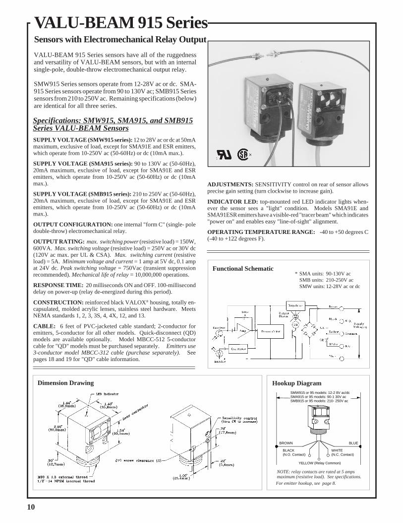
ADJUSTMENTS: SENSITIVITY control on rear of sensor allowsprecise gain setting (turn clockwise to increase gain).
INDICATOR LED: top-mounted red LED indicator lights when-ever the sensor sees a "light" condition. Models SMA91E andSMA91ESR emitters have a visible-red "tracer beam" which indicates"power on" and enables easy "line-of-sight" alignment.
OPERATING TEMPERATURE RANGE: -40 to +50 degrees C(-40 to +122 degrees F).
VALU-BEAM 915 Series sensors have all of the ruggednessand versatility of VALU-BEAM sensors, but with an internalsingle-pole, double-throw electromechanical output relay.
SMW915 Series sensors operate from 12-28V ac or dc. SMA-915 Series sensors operate from 90 to 130V ac; SMB915 Seriessensors from 210 to 250V ac. Remaining specifications (below)are identical for all three series.
Specifications: SMW915, SMA915, and SMB915Series VALU-BEAM SensorsSUPPLY VOLTAGE (SMW915 series): 12 to 28V ac or dc at 50mAmaximum, exclusive of load, except for SMA91E and ESR emitters,which operate from 10-250V ac (50-60Hz) or dc (10mA max.).
SUPPLY VOLTAGE (SMA915 series): 90 to 130V ac (50-60Hz),20mA maximum, exclusive of load, except for SMA91E and ESRemitters, which operate from 10-250V ac (50-60Hz) or dc (10mAmax.).
SUPPLY VOLTAGE (SMB915 series): 210 to 250V ac (50-60Hz),20mA maximum, exclusive of load, except for SMA91E and ESRemitters, which operate from 10-250V ac (50-60Hz) or dc (10mAmax.).
OUTPUT CONFIGURATION: one internal "form C" (single- poledouble-throw) electromechanical relay.
OUTPUT RATING: max. switching power (resistive load) = 150W,600VA. Max. switching voltage (resistive load) = 250V ac or 30V dc(120V ac max. per UL & CSA). Max. switching current (resistiveload) = 5A. Minimum voltage and current = 1 amp at 5V dc, 0.1 ampat 24V dc. Peak switching voltage = 750Vac (transient suppressionrecommended). Mechanical life of relay = 10,000,000 operations.
RESPONSE TIME: 20 milliseconds ON and OFF. 100-milliseconddelay on power-up (relay de-energized during this period).
CONSTRUCTION: reinforced black VALOX® housing, totally en-capsulated, molded acrylic lenses, stainless steel hardware. MeetsNEMA standards 1, 2, 3, 3S, 4, 4X, 12, and 13.
CABLE: 6 feet of PVC-jacketed cable standard; 2-conductor foremitters, 5-conductor for all other models. Quick-disconnect (QD)models are available optionally. Model MBCC-512 5-conductorcable for "QD" models must be purchased separately. Emitters use3-conductor model MBCC-312 cable (purchase separately). Seepages 18 and 19 for "QD" cable information.
Functional Schematic* SMA units: 90-130V ac
SMB units: 210-250V acSMW units: 12-28V ac or dc
For emitter hookup, see page 8.
NOTE: relay contacts are rated at 5 ampsmaximum (resistive load). See specifications.
BROWN BLUE
BLACK(N.O. Contact)
YELLOW (Relay Common)
WHITE(N.C. Contact)
SMW915 or 95 models: 12-2 8V ac/dcSMA915 or 95 models: 90-1 30V acSMB915 or 95 models: 210- 250V ac
Hookup Diagram
10
VALU-BEAM 915 SeriesSensors with Electromechanical Relay Output

All emitter/receiver pairs:Response: 20ms on/offBeam: infrared, 880nmVisible red "tracer beam"
RETROREFLECTIVEMODE
A visible-red light beam reduces the potential for false signals from highlyreflective objects ("proxing") and simplifies alignment. AG (anti-glare) modelspolarize the emitted light and filter out unwanted reflections, making their usepossible in applications otherwise unsuited to retroreflective sensing (and wherereduced excess gain is acceptable). Maximum range with all units is attained whenusing the model BRT-3 3" corner cube reflector. See the Banner product catalog fordetails about available retroreflective materials.
SMA91E & SMW95RVoltage: 12 to 28V ac/dc, ("E": 10-250V ac/dc)Range: 200 feet (60m)Effective beam: 0.5" dia.
SMA91E &SMA95R or SMB95RVoltage:SMA95R 90 to 130V ac,SMB95R 210 to 250V ac,("E": 10-250V ac/dc)Range: 200 feet (60m)Effective beam: 0.5" dia.
SMA91ESR &SMA95RSR orSMB95RSRVoltage:SMA95RSR 90 to 130V ac,SMB95RSR 210 to 250V ac,("ESR": 10 to 250V ac/dc)Range: 10 feet (3m)Effective beam: 0.14" dia.
SMA91ESR & SMW95RSRVoltage: 12 to 28V ac/dc,("ESR": 10-250V ac/dc)Range: 10 feet (3m)Effective beam: 0.14" dia.
SMW915LVVoltage: 12 to 28V ac/dc
SMA915LVVoltage: 90 to 130V ac
SMB915LVVoltage: 210 to 250V ac
Range: 6 inches to 30 feet (9m)Response: 20ms on/offBeam: visible red, 650nm
Opposed mode sensors have higher excess gain than other models, andtherefore should be used whenever possible. The small size of thesesensors makes them ideal for many conveyor applications, and their smalleffective beam size (particularly of the ESR/RSR models) enables themto reliably detect relatively small objects. ESR and RSR models also havea wide beam angle for very forgiving alignment within the 10-foot range.VALU-BEAM opposed mode sensors have a visible red "tracer beam"which greatly simplifies sensor alignment. E and R models have a narrowbeam angle which allows receivers to be placed on relatively close centers(at close range) in multiple sensor arrays.
Range: 1 to 15 feet (4,5m)Response: 20ms on/offBeam: visible red, 650nm(with polarizing filter)
SMW915LVAG(anti-glare filter)Voltage: 12 to 28V ac/dc
SMA915LVAG(anti-glare filter)Voltage: 90 to 130V ac
SMB915LVAG(anti-glare filter)Voltage: 210 to 250V ac
1000
100
10
1 1 FT 10 FT 100 FT 1000 FT
DISTANCE
SMA91E & SMW95R orSMA95R or SMB95R
EXCESS
GAINI
1000
100
10
1.1 FT 1 FT 10 FT 100 FT
DISTANCE
EXCESS
GAINI
SMA91ESR &SMW95ESR or SMA95ESR or SMB95ESR
1000
100
10
1.1 FT 1 FT 10 FT 100 FT
DISTANCE
with 3"reflector(BRT-3)
withBRT-T tape
with 1"reflector (BRT-1)
SMW915LV,SMA915LV,SMB915LV
EXCESS
GAINI
1000
100
10
1
DISTANCE
SMW915LVAG,SMA915LVAG,SMB915LVAG
with one BRT-33" retroreflector
.1 FT 1 FT 10 FT 100 FT
EXCESS
GAINI
0
0
INCHES
OPPOSED DISTANCE--FEET
20
40
60
20
40
60
50 100 150 200 250
SMA91E with SMW95Ror SMA95R or SMB95R
2 4 6 8 100
0
4
8
12
4
8
12
INCHES
OPPOSED DISTANCE--FEET
SMA91ESR with SMW95RSR or SMA95RSR or SMB95RSR
3 6 9 12 150
0
1
2
3
1
2
3
INCHES
DISTANCE TO REFLECTOR--FEET
with BRT-3 REFLECTOR
SMW915LVAG, SMA915LVAG,SMB915LVAG
6 12 18 24 300
0
2
4
6
2
4
6
INCHES
DISTANCE TO REFLECTOR--FEET
with BRT-3 REFLECTOR
SMW915LV, SMA915LV,SMB915LV
Beam PatternSensing Mode
OBJECT
RETROREFLECTIVE TARGET
OPPOSED Mode
OBJECT
EMITTER RECEIVER
VALU-BEAM 915 Series SensorsModels Excess Gain
11

The amount of light that is returned to reflective mode sensors (diffuse,convergent, and divergent types) is dramatically influenced by the reflectivityof the surface being sensed. Excess gain curves are plotted using a white testcard, rated at 90% reflectance. Any other material surface may be ranked forits reflectivity as compared against this 90% reflectance white test card:
MATERIAL REFLECTIVITY EXCESS GAIN REQUIRED
*NOTE: for materials with shiny or glossy surfaces, the reflectivity figure represents themaximum light return, with the sensor beam exactly perpendicular to the material surface.
These sensors operate by detecting the reflection of their own light fromthe object being sensed, and therefore require no special reflectors. Theyare ideal for use when the reflectivity and profile of the object are sufficientto return a large amount of emitted light back to the sensor. Choose "DSR"models for best response to objects at close range.
CONVERGENT Mode VALU-BEAM convergent sensors produce a precise .06" diameter sens-ing spot at a focus point 1.5" in front of the sensor lens. Due to their verynarrow depth of field, they excel at detecting small objects only a fractionof an inch away from backgrounds. A visible red sensing beam simplifiesalignment.
SMW915DSRVoltage: 12 to 28V ac/dc
SMA915DSRVoltage: 90 to 130V ac
SMB915DSRVoltage: 210 to 250V ac
Range: 15 inches (38cm)Response: 20ms on/offBeam: infrared, 880nm
SMW915CVVoltage: 12 to 28V ac/dc
SMA915CVVoltage: 90 to 130V ac
SMB915CVVoltage: 210 to 250V ac
Focus at 1.5" (38mm)Response: 20ms on/offBeam: visible red, 650nm
90%80%55%47%35%70%70%
Kodak white test cardWhite paperNewspaper with printTissue paper: 2 ply
1 plyKraft paper cardboardBeer foam
11.11.61.92.61.31.3
Dimension lumber (pine,clean, dry)Rough wood pallet(clean)*Clear plastic*Opaque white plastic*Opaque black plasticBlack neopreneBlack rubber tire wall*Aluminum, unfinished*Aluminum, blackanodized*Stainless steel,microfinish
75%
20%
40%87%14%4%1.5%140%
115%
400%
1.2
4.5
2.31.06.422.5600.6
0.8
0.2
MATERIAL REFLECTIVITY EXCESS GAIN REQUIRED
1000
100
10
1.1 IN 1 IN 10 IN 100 IN
DISTANCE
(Range based on 90%reflectance white test card)
SMW915D, SMA915D,SMB915DE
XCESS
GAINI
1000
100
10
1.1 IN 1 IN 10 IN 100 IN
DISTANCE
Range base on 90%reflectance white test card
SMW915DSR,SMA915DSR,SMB915DSR
EXCESS
GAINI
1000
100
10
1.1 IN 1 IN 10 IN 100 IN
DISTANCE
SMW915CV,SMA915CV,SMB915CV
(Range based on 90%reflectance white testcard)
EXCESS
GAINI
6 12 18 24 300
0
.25
.50
.75
.25
.50
.75
INCHES
DISTANCE TO 90% WHITE TEST CARD--INCHES
SMW915D,SMA915D,SMB915D
3 6 9 12 150
0
.25
.50
.75
.25
.50
.75
INCHES
DISTANCE TO 90% WHITE TEST CARD--INCHES
SMW915DSR,SMA915DSR,SMB915DSR
.50
0
.03
.06
.09
.03
.06
.09
1.0 1.5 2.0 2.5
INCHES
DISTANCE TO 90% WHITE TEST CARD--INCHES
SMW915CV, SMA915CV,SMB915CV
Application Note:Relative Reflectivity of Materials
Models Excess Gain Beam PatternSensing Mode
SMA915DVoltage: 90 to 130V ac
SMB915DVoltage: 210 to 250V ac
Range: 30 inches (76cm)Response: 20ms on/offBeam: infrared, 880nm
SMW915DVoltage: 12 to 28V ac/dc
DIFFUSE Mode
OBJECT
OBJECT
VALU-BEAM 915 Series Sensors
12

Beam PatternSensing Mode
The powerful modulated vis-ible beam of these sensorsmakes them compatible withall Banner plastic fiber opticassemblies, and their fiberfittings will accomodate bothterminated and unterminatedtype assemblies. Plastic fi-bers are ideal for short-rangesensing where the environ-ment is not severe. Plasticfiber optic model informationmay be found in the Bannerproduct catalog
These sensors will also inter-face with Banner glass fiberoptic assemblies.
FIBER OPTIC Mode(plastic fibers)
FIBER OPTIC Mode(glass fibers)
SMW915FPVoltage: 12 to 28V ac/dc
SMA915FPVoltage: 90 to 130V ac
SMB915FPVoltage: 210 to 250V ac
Range: see E.G. curvesResponse: 20ms on/offBeam: visible red, 650nm
VALU-BEAM 915 Series Sensors
10
1
DISTANCE
100
1000
.1 IN 1 IN 10 IN 100 IN
IT23S fibers
IT13S fibers
Opposedmode,glass fibers
SMW915F,SMA915F,SMB915F
EXCESS
GAINI
1000
100
10
1.1 FT 1 FT 10 FT 100 FT
DISTANCE
with L9 lens and BT13S fibers
with L16F lensand BT13Sfibers
SMW915F, SMA915F,SMB915F Retroreflective
mode, w/BRT-3 3" target
EXCESS
GAINI
1000
100
10
1.1 IN 1 IN 10 IN 100 IN
withBT13S fibers
withBT23S fibers
DISTANCE
Range based on 90%reflectance white test card
Diffuse mode
SMW915F, SMA915F,SMB915F
EXCESS
GAINI
1
10
100
1000
.1 IN 1 IN 10 IN 100 IN
PIT46Uwith L2lenses
PIT26U,no lens
DISTANCE
Opposed mode,plastic fibers
PIT46U,no lenses
SMW915FP,SMA915FP,SMB915FPE
XCESS
GAINI
1
10
100
1000
.01 IN .1 IN 1 IN 10 IN
withPBT46U fiber
withPBT26Ufiber
DISTANCE
SMW915FP, SMA915FP,SMB915FP
Range based on 90% reflectancewhite test card
Diffuse mode,plastic fibers
EXCESS
GAINI
4 8 12 16 200
0
1
2
3
1
2
3
INCHES
OPPOSED DISTANCE --INCHES
IT23S fibers
IT13S fibers
opposed mode
SMW915F, SMA915F, SMB915F
.3 .60
0
.025
1.2 1.5
.050
.075
.1
.025
.050
.075
.1
.9
BT23SBT13S
Diffuse mode
INCHES
DISTANCE TO 90% WHITE TEST CARD--INCHES
SMW915F, SMA915F, SMB915F
4 8 12 16 200
0
2
4
6
2
4
6
w/L9 lens w/L16F lens
INCHES
DISTANCE TO REFLECTOR--FEET
BT13S fiber, retroreflectivemode, with BRT-3 reflector
SMW915F, SMA915F,SMB915F
1 2 30 4
0
.6
5
1.2
1.8
.6
1.2
1.8
PIT26U PIT46U
Opposed mode
INCHES
OPPOSED DISTANCE--INCHES
SMW915FP, SMA915FP,SMB915FP
.3 .60
0
.05
.10
.15
.05
.10
.15
1.2 1.5.9
PBT26U PBT46U
Diffuse mode
INCHES
DISTANCE TO 90% WHITE TEST CARD--INCHES
SMW915FP, SMA915FP, SMB915FP
Models Excess Gain
Environmental Factors for Plastic Fiber Optics
OPERATING TEMPERATURE OF FIBER OPTIC ASSEMBLIES: -30 to+70 degrees C (-20 to +158 degrees F).
CHEMICAL RESISTANCE OF FIBER OPTIC ASSEMBLIES: the acryliccore of the monofilament optical fiber will be damaged by contact with acids,strong bases (alkalis), and solvents. The polyethylene jacket will protect theoptical fiber from most chemical environments; however, materials maymigrate throught the jacket with long-term exposure. Samples of plastic fiberoptic material are available from Banner for testing and evaluation.
SMW915FVoltage: 12 to 28V ac/dc
SMA915FVoltage: 90 to 130V ac
SMB915FVoltage: 210 to 250V ac
Range: see E.G. curvesResponse: 20ms on/offBeam: infrared, 880nm
OPPOSED
OBJECT
OBJECT
RETROREFLECTIVE TARGET
RETRO
DIFFUSE
OBJECT
OBJECT
DIFFUSE
OPPOSED
OBJECT
13
Fiber optic sensing is oftenthe answer when, due to spaceor environmental limitations,the sensor itself cannot beplaced at the actual sensingposition. These sensors' pow-erful modulated infraredbeam is compatible with allBanner glass fiber optics inthe opposed, retroreflective,and diffuse sensing modes.Banner glass fiber optic se-lection information may befound in the product catalog.Sensor/fiber interface is wa-terproof to maintain completesensing system moisture re-jection.

VALU-BEAM 990 Series sensors boast the same high opticalperformance offered by the front-line 912 Series, and alsocontain a built-in 6-digit totalizing counter. Sensor models areavailable for opposed, retroreflective, and convergent beamsensing modes. In addition, there are models for use with bothglass and plastic fiberoptics.
A special infrared retroreflective version is available, which isdesigned for counting people passing through entry ways. It hasbuilt-in on/off time delays to minimize the chance of multiplecounts.
The 990 Series VALU-BEAM's 6-digit LCD counter is resetsimply by touching the area of the housing shown with thepermanent magnet supplied with the sensor (see dimensiondrawing, below). Standard models automatically reset to zeroupon power-up.
Memory backup option: SMA990 Series sensors with internal memory backup for maintaining "count memory" while power isremoved are available by special order. These models will "hold" a count for over 100 hours, and are indicated by the model numbersuffix MB (i.e., "SMA990LVMB" is the memory backup version of sensor model SMA990LV). Contact the factory for availibilityand pricing of these models.
SMA990 Series sensors wire directly to either 10 to 250V ac (50/60Hz) or 12 to 115V dc.
Dimensions, SMA990 Series VALU-BEAMs
VALU-BEAM 990 Series Sensorswith Built-in Totalizing Counter
L1 L2
10 to 250V ac, 50/60Hz or 12 to 115V dc
+ Brown Blue
Observe proper polarity for DC hookups.AC hookups have no polarity.
Hookup Diagram
14
SUPPLY VOLTAGE: 10 to 250V ac, 50/60Hz or 12 to 115Vdc at less than 20 milliamps.
SENSOR RESPONSE: 15 milliseconds LIGHT, 15 millisec-onds DARK (except SMA990LT, page 16). 100 milliseconddelay on power up (no counts are entered during this time).Models with memory backup have no power-up delay. Note:Some models with memory backup may increment 1 count uponreapplication of power.
COUNT ENTRY: counts are entered on DARK-to-LIGHTtransition.
COUNT RESET: in standard models, counter is reset to zeroautomatically upon applying power to the sensor. All modelsmay be reset by touching the housing on top of the sensor (seebelow) with a permanent magnet (supplied with sensor).
CONSTRUCTION: reinforced black VALOX® housing, to-tally encapsulated circuitry, molded o-ring sealed lenses or fiberfittings, stainless steel hardware. Meets NEMA standards 1, 2,3, 3S, 4, 4X, 12, and 13.
CABLE: 6 feet (2m) of PVC-jacketed 2-conductor cable isstandard. Three-pin quick-disconnect ("QD") models are avail-able optionally (one conductor goes unused). Order modelMBCC-312 3-conductor cable for "QD" models (page 18).
INDICATOR LED: top-mounted red LED indicator lightswhenever the sensor "sees" its modulated light source.
OPERATING TEMPERATURE RANGE: 0 to 50 degrees C(32 to 122 degrees F).
SPECIFICATIONS, SMA990 SERIES VALU-BEAM SENSORS

SMA990LVVoltage: 10 to 250V acor 12 to 115V dc
Range: 6 inches to 30 feet (9m)
Beam: visible red, 650nm
SMA91ESR & SMA99RSRVoltage: 10 to 250V acor 12 to 115V dc;("ESR": 10-250V ac/dc)
Range: 10 feet (3m)
Beam: infrared, 880nm;visible red tracer beam
Effective beam: 0.14" dia.
A visible-red light beam reduces the potential for false signals from highly reflectiveobjects ("proxing") and simplifies alignment. The AG (anti-glare) model polarizesthe emitted light and filters out unwanted reflections, making its use possible inapplications otherwise unsuited to retroreflective sensing (and where reducedexcess gain is acceptable). Maximum range with all units is attained when using themodel BRT-3 3" corner cube retroreflector. See the Banner product catalog fordetails about available retroreflective materials.
VALU-BEAM 990 Series Sensors
Opposed mode sensors have higher excess gain than other models, and thereforeshould be used whenever possible. Opposed mode is the most reliable sensing modefor counting opaque materials. The small size of these sensors makes them ideal formany conveyor applications, and their small effective beam size (particularly of theESR/RSR models) enables them to reliably count relatively small objects. ESR andRSR models also have a wide beam angle for very forgiving alignment within the10-foot range. VALU-BEAM opposed mode sensors have a visible red "tracerbeam" which greatly simplifies sensor alignment.
SMA91E &SMA99RVoltage: 10 to 250V acor 12 to 115V dc;("E": 10-250V ac/dc)
Range: 200 feet (60m)
Beam: infrared, 880nm;visible red tracer beam
Effective beam: 0.5" dia.
1000
100
10
1 1 FT 10 FT 100 FT 1000 FT
DISTANCE
SMA91E &SMA99RE
XCESS
GAINI
1000
100
10
1.1 FT 1 FT 10 FT 100 FT
DISTANCE
SMA91ESR &SMA99RSRE
XCESS
GAINI
1000
100
10
1.1 FT 1 FT 10 FT 100 FT
DISTANCE
with 3"reflector(BRT-3)
withBRT-T tape
with 1"reflector (BRT-1)
SMA990LVEXCESS
GAINI
3 6 9 12 150
0
1
2
3
1
2
3
INCHES
DISTANCE TO REFLECTOR--FEET
SMA990LVAG
with BRT-3 REFLECTOR
6 12 18 24 300
0
2
4
6
2
4
6
INCHES
DISTANCE TO REFLECTOR--FEET
with BRT-3 REFLECTOR
SMA990LV
2 4 6 8 100
0
4
8
12
4
8
12
INCHES
OPPOSED DISTANCE--FEET
SMA91ESR & SMA99RSR
0
0
INCHES
OPPOSED DISTANCE--FEET
20
40
60
20
40
60
50 100 150 200 250
SMA91E & SMA99R
1000
100
10
1
DISTANCE
SMA990LVAG
with one BRT-33" retroreflector
.1 FT 1 FT 10 FT 100 FT
EXCESS
GAINI
Sensing Mode Models Excess Gain Beam Pattern
SMA990LVAGVoltage: 10 to 250V acor 12 to 115V dc
Range: 1 to 15 feet (4,5m)
Beam: visible red, 650nm(with polarizing filter)
RETROREFLECTIVE
OPPOSED Mode
15

SMA990LTVoltage: 10 to 250V acor 12 to 115V dcRange: 30 feet (9m)Beam: infrared, 940nm
VALU-BEAM model SMA990LT is designed specifically for "people counting".Its strong (30 foot range) infrared beam is invisible to the eye, and a built-in 1/10second on/off delay helps prevent multiple counts. Maximum retroreflective signalstrength is attained when using the model BRT-3 corner-cube retroreflector. Otherretroreflective materials may also be used (see Banner product catalog for descrip-tive information).
VALU-BEAM convergent sensors produce a precise .06" diameter visible redsensing spot at a focus point 1.5" in front of the sensor lens. Due to its very narrowdepth of field, this model excels at counting small objects only a fraction of an inchaway from backgrounds. This convergent sensor may be used for reliable countingof some radiused products which flow past at a fixed distance from the sensor lens.
SMA990CVVoltage: 10 to 250V acor 12 to 115V dcFocus at 1.5" (38mm)Beam: visible red, 650nm
SMA990FPVoltage: 10 to 250V acor 12 to 115V dcRange: see E.G. curvesBeam: visible red, 650nm
Environmental Factors for Plastic Fiber Optics
10
1
DISTANCE
100
1000
.1 FT 1 FT 10 FT 100 FT
with BRT-3 3"reflectorwith BRT-1 1"
reflector
withBRT-Ttape
SMA990LTEXCESS
GAINI
1000
100
10
1.1 IN 1 IN 10 IN 100 IN
DISTANCE
(Range based on 90%reflectance white testcard)
SMA990CVEXCESS
GAINI
1
10
100
1000
.1 IN 1 IN 10 IN 100 IN
PIT46Uwith L2lenses
PIT26U,no lens
DISTANCE
Opposed mode,plastic fibers
PIT46U,no lenses
SMA990FPEXCESS
GAINI
1
10
100
1000
.01 IN .1 IN 1 IN 10 IN
withPBT46U fiber
withPBT26Ufiber
DISTANCE
SMA990FP
(Range based on 90% reflectancewhite test card)
Diffuse mode,plastic fibers
EXCESS
GAINI
0
0
2
4
6
2
4
6
6 12 18 24 32
INCHES
SMA990LT
DISTANCE TO REFLECTOR--FEET
with BRT-3 reflector
.50
0
.03
.06
.09
.03
.06
.09
1.0 1.5 2.0 2.5
INCHES
DISTANCE TO 90% WHITE TEST CARD--INCHES
SM990CV
1 2 30 4
0
.6
5
1.2
1.8
.6
1.2
1.8
PIT26U PIT46U
Opposed mode
INCHES
OPPOSED DISTANCE--INCHES
SMA990FP
.3 .60
0
.05
.10
.15
.05
.10
.15
1.2 1.5.9
PBT26U PBT46U
Diffuse mode
INCHES
DISTANCE TO 90% WHITE TEST CARD--INCHES
SMA990FP
Sensing Mode Models Beam PatternExcess Gain
The powerful modulatedvisible beam of this sensormakes it compatible withall Banner plastic fiberoptic assemblies. Bannerplastic fibers are an eco-nomical alternative to glassfibers when environmen-tal conditions allow (seebelow). Banner plastic fi-ber optics are available intwo core diameters andwith various sensing tipstyles. Standard length is 6feet. See the Banner prod-uct catalog for more fiberoptic information.
VALU-BEAM 990 Series Sensors
CONVERGENT Mode
FIBER OPTIC Mode(plastic fiber optics)
RETROREFLECTIVE
DIFFUSE
OBJECT
OPPOSED
OBJECT
16
OPERATING TEMPERATURE OF FIBER OPTIC ASSEMBLIES: -30 to +70° C (-20 to +158° F).CHEMICAL RESISTANCE OF FIBER OPTIC ASSEMBLIES: the acrylic core of the monofilament opticalfiber will be damaged by contact with acids, strong bases (alkalis), and solvents. The polyethylene jacket willprotect the optical fiber from most chemical environments; however, materials may migrate through the jacketwith long-term exposure. Samples of plastic fiber optic material are available from Banner for testing andevaluation.

Memory Backup ("MB") option: SMA990 Series sensors with internal memory backup for maintaining "count memory"are available by special order. These models, which will "hold" a count for over 100 hours, are indicated by the model suffix "MB"(example: the memory backup version of model SMA990LV is "SMA990LVMB"). Contact the factory for availability andpricing on these models.
Quick Disconnect ("QD") option: The VALU-BEAM QD option allows quick and easy removal or replacement ofVALU-BEAM sensors in the field. QD option VALU-BEAM 990 Series sensors have a 3-pin male connector, built into thesensor's base, which mates with the model MBCC-312 3-conductor female SO-type quick-disconnect cable (one wire goesunused). To specify the QD option on a sensor, simply add the letters "QD" to the end of the sensor's model number. (Example:the QD version of the SMA990FMB is "SMA990FMBQD".) Model MBCC-312 SJT-type cable (12' length) must be orderedseparately. See drawings, page 18.
30-foot cable option: Standard VALU-BEAM sensor models (non-QD types, which are normally supplied with a 6-foot longPVC-covered cable), may optionally be supplied with a 30-foot PVC-covered cable. Thirty feet is the most readily-availablelength; lengths longer than 30 feet may also be quoted.
Accessory Mounting Bracket model SMB900: Accessory mounting bracket model SMB900 has curved mountingslots for versatility in mounting and orientation. The sensor mounts to the bracket by its threaded base, using a jam nut and lock-washer (both included). The bracket accommodates both standard and "QD" sensor models. Bracket material is 11-gauge zinc-plated steel. The curved mounting slots have clearance for 1/4" screws. See drawings, page 20.
Accessory Mounting Bracket model SMB30SM: This is a swivel mounting bracket. The base of the VALU-BEAMsensor threads into the bracket's captive swivel ball, which is then held firmly in the desired position when the bracket's twomounting bolts are tightened.
Options and Accesories for SMA990 Series Sensors
Beam PatternSensing Mode Models Excess Gain
SMA990FVoltage: 10 to 250V acor 12 to 115V dcRange: see E.G. curvesBeam: infrared, 880nm
FIBER OPTIC Mode
10
1
DISTANCE
100
1000
.1 IN 1 IN 10 IN 100 IN
IT23S fibers
IT13S fibers
Opposedmode,glass fibers
SMA990F
EXCESS
GAINI
1000
100
10
1.1 FT 1 FT 10 FT 100 FT
DISTANCE
with L9 lensand BT13Sfibers
with L16F lensand BT13Sfibers
Retroreflective mode, w/BRT-3 3" target
SMA990F
EXCESS
GAINI
1000
100
10
1.1 IN 1 IN 10 IN 100 IN
withBT13S fibers
withBT23S fibers
DISTANCE
(Range based on 90%reflectance white test card)
Diffuse mode
SMA990F
EXCESS
GAINI
0 with L9 lens with L16F lens
4 8 12 16 200
2
4
6
2
4
6
INCHES
DISTANCE TO REFLECTOR--FEET
BT13S fiber, retroreflectivemode, with BRT-3 reflector
SMA990F
.3 .60
0
.025
1.2 1.5
.050
.075
.1
.025
.050
.075
.1
.9
BT23SBT13S
Diffuse modeINCHES
DISTANCE TO 90% WHITE TEST CARD--INCHES
SMA990F
4 8 12 16 200
0
1
2
3
1
2
3
INCHES
IT23S fibers
IT13S fibers
Opposed mode
SMA990F
OPPOSED DISTANCE --INCHES
(glass fiber optics)
DIFFUSE
OPPOSED
OBJECT
OBJECT
RETROREFLECTIVE TARGET
RETRO
17
Fiberoptic sensing is often theanswer when, due to space orenvironmental limitations, thesensor itself cannot be placedat the actual sensing position.This sensor's powerful modu-lated infrared beam is com-patible with all Banner glassfiber optics in the opposed,retroreflective, and diffusesensing modes. Glass fiberoptic selection informationmay be found in the Bannercatalog. The sensor/fiber in-terface is waterproof to main-tain complete sensing systemmoisture rejection.
Opposed mode fiber opticsensing is often employed inparts counting applications.Fiber optics can be built withsensing ends having windowsthat conform to the size andprofile of the part. This allowsmost efficient use of thesensor's emitted light energy.Refer to the Banner productcatalog for more information.
VALU-BEAM 990 Series Sensors

18
VALU-BEAM Modifications and Accessories
All Banner VALU-BEAM sensors are available with the "QD"(Quick-Disconnect) option (below). A 3, 4, or 5-pin connector
(depending upon the VALU-BEAM model), built into the sensor's base, mates with the SJT-typequick disconnect cable described below. Cable must be ordered separately.
The diagrams below show pin configurations for 3, 4, and 5 pin "QD" connectors, which are locatedat the base of VALU-BEAM sensors having the "QD" option. Mirror-image pin numbering is usedfor the connectors of the mating cables, as shown below. Male contact pins are used in the sensorconnectors. The cable connectors have female receptacles for wiring safety.
Standard VALU-BEAM sensors (non-"QD" models, which are normally supplied with an attached6-foot long PVC-covered cable) may instead be supplied optionally with an attached 30-foot PVC-covered cable. Thirty feet is the most readily available length, but lengths longer than 30 feet mayalso be quoted.
Quick-Disconnect ("QD") Cable Option
Pin Configurations for 3-, 4-, and 5-pin "QD" Connectors
Side View, MBCC QD Cable Connector
Dimensions, "QD" Sensors
912 Series sensors withsolid-state relay output
915 Series sensors withe/m relay output
990 Series sensors withbuilt-in totalizing
counters
QD cable modeland end view
MBCC-312
MBCC-412
MBCC-512
All AC sensors:model prefixes SM2A912,
SM2A91R, SMA912, SMA91R
All emitters:model prefix SMA91E
All DC sensors:model prefix SM912
(not used)
All emitters:model prefix SMA91E
(not used)
All sensors (except emitters):model prefixes
SMA915, SMA91R,SMB915, SMB91R
SMW915, SMW91R
All sensors:model prefixes
SMA990, SMA91E
(not used)
(not used)
Quick Disconnect Cables for VALU-BEAM® Sensors with "QD" Option(cables must be purchased separately)

VALU-BEAM Accessories
19
RF1-2NPS Compression Fitting for attachingarmored cable or PVC tubing to VALU-BEAMsensors (not for "QD" models).
Model AC-6 armored cable jacket for VALU-BEAM sensors (not for "QD" models). Six-footlength. Size: I.D. = 5/16"; O.D. = 7/16".
Model PVC-6 flexible PVC tubing for VALU-BEAM sensors (not for "QD" models). Six-footlength. Size: I.D. = 1/4"; O.D. = 3/8".
Compression Fitting PVC Cable Tubing
Extension CableExtension cable in 100-foot lengths:Model EC312-100 4-wire cable for SM912 Series dc sensors. Wire colors: brown, blue, black, white.
Model EC312A-100 2-wire cable for emitters and SM2A912 Series 2-wire ac sensors and SMA990series. Wire colors: brown, blue.
Model EC900A-100 3-wire cable for SMA912 Series ac sensors. Wire colors: brown, blue, black.
Model EC915-100 5-wire cable for SMA915, SMB915, and SMW915 Series ac/dc sensors. Wirecolors: brown, blue, black, white, yellow.
NOTE: extension cable may be ordered in lengths greater than 100 feet on a quote basis.
Armored Jacket
Upper Covers (lens assemblies)
VALU-BEAM upper covers (above). Upper cover model UC-900J (on the right in the photo) is a flat, clear Lexan® window whichacts as a dust cover for the lens area when the sensor is mountedfacing up. The UC-900J may be attached to the following VALU-BEAMs: E, R, ESR, RSR, LV, and D.
VALU-BEAM "upper covers" consist of a bezel, a lens, and mountinghardware. Depending upon the model of VALU-BEAM in use, they allowsensing mode and/or sensing range changes in the field.
Table I below lists the various VALU-BEAM sensor types and the upper covermodels they are supplied with. It tells you which upper cover to order for strictlyreplacement purposes. VALU-BEAMs are identified by their model numbersuffixes, which designate their sensing mode. For example, an SM912LVAG orSM2A912LVAG sensor uses a model UC-900AG upper cover.
Table II lists the sensing mode and range changes that may be accomplished bysubstituting a different upper cover. For example, if you want to convert an F(fiberoptic) type VALU-BEAM to a D (diffuse) type, order and install upper covermodel UC-900L. The conversions listed are direct model conversions which maybe made simply by changing VALU-BEAM upper cover assemblies. Otherconversions are possible: contact the Banner applications staff with any questions.
Table I: Replacement CoversUses upper covermodel:UC-900AGUC-900CUC-900DSRUC-900FUC-900FPUC-900L
Use UPPERCOVER:UC-900LUC-900LUC-900LUC-900LUC-900DSR
VALU-BEAMType:LVAGCV, CDSR, ESR, RSRFFPE, R, LV, D
To change:
LV to LVAGLV to CVD to DSRD to FDSR to FEF to ESRRF to RSR
Table II: Mode/Range Change Cross-reference
To change:
LVAG to LVCV to LVDSR to DF to DF to DSR
UseUPPER COVER:UC-900AGUC-900CUC-900DSRUC-900FUC-900FUC-900DSRUC-900DSR

Banner Engineering Corp. 9714 Tenth Ave. No. Minneapolis, MN 55441 Telephone: (612)544-3164 FAX (applications): (612)544-3573
SMB900 Mounting BracketAccessory mounting bracketmodel SMB900 has curved mount-ing slots for versatility in mount-ing and orientation. The sensormounts to the bracket by itsthreaded base, using a jam nut andlockwasher (both included). Thebracket material is 11-gauge zinc-plated steel. The curved mountingslots have clearance for 1/4"screws.
SMB30S Mounting BracketSwivel mounting bracket modelSMB30S offers the ultimate in flex-ibility and convenience. TheSMB30S bracket mounts by itsbase. The base of the VALU-BEAM sensor threads into the cap-tive "ball" of the bracket, which islocked snugly in position when thetwo clamping/mounting bolts aretightened. Bracket material is blackVALOX ®. Hardware is stainlesssteel, and bolts are included.
!WARNING VALU-BEAM photoelectric presence sensors do NOT include the self-checking redundant circuitry necessaryto allow their use in personnel safety applications. A sensor failure or malfunction can result in either an energized or a de-energizedsensor output condition.
Never use these products as sensing devices for personnel protection. Their use as safety devices may create an unsafe condition whichcould lead to serious injury or death.
Only MACHINE-GUARD and PERIMETER-GUARD Systems, and other systems so designated, are designed to meet OSHA andANSI machine safety standards for point-of-operation guarding devices. No other Banner sensors or controls are designed to meet these standards, andthey must NOT be used as sensing devices for personnel protection.
This black neoprene assembly easily slips over the prewired cable and threads into the base of a VALU-BEAM sensor. The flexible extender prevents sharp cable bends and extends the life of cable that issubject to repeated flexing.
The HF1-2NPS includes a neoprene gland that compresses around the VALU-BEAM cable to providean additional seal against moisture.
This flexible conduit protector is resistant to gasoline, alcohol, oil, grease, solvents, and weak acids. Ithas a working temperature range of -30° to +100°C (-22 to +212°F). It is UL recognized and CSAcertified.
The HF1-2NPS also threads into the base of OMNI-BEAM, MULTI-BEAM, MAXI-BEAM, and SM30Series sensors. It is sold in packages of 10 pieces.
HF1-2NPS Flexible Cable Protector
VALU-BEAM Accessories