specifications versarray 212 - peavey electronics x 2.5" in neo midranges, arranged in two...
TRANSCRIPT

1
Frequency response, 1 meter on-axis, swept-sine in anechoic environment:
90 Hz to 20 kHz (±3 dB, with processing)
Usable low frequency limit(-10 dB point):
85 Hz (with processing)
Power handling:Low frequency section:
1,000 watts continuous2,000 watts program4,000 watts peak
Mid frequency section:200 watts continuous400 watts program800 watts peak
High frequency section:200 watts continuous400 watts program800 watts peak
Sound pressure level, 1 watt,1 meter in anechoic environment:
Low frequency section (Both 12” woofers in parallel):
99 dB SPL (2.00 V input)
Mid frequency section:101 dB SPL (2.83 V input)
High frequency section:102 dB SPL (2.83 V input)
Maximum sound pressure level(1 meter)*:
Low frequency section:129 dB SPL continuous135 dB SPL peak
Mid frequency section:124 dB SPL continuous130 dB SPL peak
High frequency section:125 dB SPL continuous131 dB SPL peak
*Note: This spec is for one module at 1 meter, a line array of 8 units has much higher output at distance due to line source effect where SPL falls of at 3 dB per distance doubling rather than 6 dB. All peak levels confirmed by measurement.
Normal radiation angle measured at -6 dB point of polar response:
70° horizontal by 15° vertical(One module only; straight line array of more than 1 module narrows vertical dispersion accordingly)
Radiation angle measured at -6 dB point of polar response:
500 Hz to 1.6 kHz:Horizontal 158° +/- 55°Vertical 90° +/- 45°
1.6kHz to 5 kHz:Horizontal 84° +/- 15°Vertical 30° +/- 10°
5 kHz to 16 kHz:Horizontal 55° +/- 20°Vertical 10° +/- 4°
Directivity Factor, Q (Mean, 1.6 kHz to 12.5 kHz):
47.6, +92/-36
Directivity Factor, Di (Mean, 1.6 kHz to 12.5 kHz):
16.8 dB, +4.6 dB/-6.3 dB
Transducer complement:Low frequency section:
2 x 12" woofer, 1212-4 Neo Black Widow® 4” Dual VC Woofer in a sealed box
Mid frequency section:10 x 2.5" in Neo Midranges, arranged in two banks of 5 each
High frequency section:4 x 4.75" in Planar Dynamic Ribbon Tweeter line sources on a manifold-loaded waveguide
Box tuning frequency (Sealed): Low frequency section: 94 Hz
Midrange section: 220 Hz
Harmonic Distortion*: 1 watt power 2nd Harmonic: 200 Hz 0.32% 1 kHz 0.47% 4 kHz 048% 3rd Harmonic: 200 Hz < 0.10% 1 kHz 0.19% 4 kHz 0.18% 10 watt power 2nd Harmonic: 200 Hz 1.38% 1 kHz 1.52% 4 kHz 0.72% 3rd Harmonic: 200 Hz < 0.10% 1 kHz 0.32% 4 kHz 0.16%
*Note: Distortion levels may be measurement setup limited in some instances
Electroacoustic crossover point, Peavey active digital crossover:(Applies to VSX and Digitool settings provided by Peavey)
Sub - Low frequency: 120 Hz at 24 dB/octave
Low frequency - Mid frequency: 440 Hz at 24 dB/octave
Mid frequency - High frequency: 2.51 kHz at 24 dB/octave
Recommended active crossover frequency region and slope: Sub - Low frequency: 125 Hz at 24 dB/octave LR
Low frequency - Mid frequency: 440 Hz at 24 dB/octave LR
Mid frequency - High frequency: 2.6 kHz at 24 dB/octave
Time Offset: Low frequency: -0.33 milliseconds Mid frequency: -0.25 milliseconds
SPECIFICATIONS Versarray™ 212

2
Impedance (Z): Low frequency (each): Nominal: 8.0 Ω Minimum: 6.5 Ω
Mid frequency (each): Nominal: 6.0 Ω Minimum: 4.8 Ω
High frequency (each): Nominal: 8.0 Ω Minimum: 6.2 Ω
Input connections: 2 x Neutrik® Speakon® 8-pin jacks in parallel; 4 x Neutrik Speakon 4-pin jacks, one set in parallel for the lows (each woofer independently accessible), and one set in parallel for the midrange and highs
Enclosure materials and finish:18, mm 13-ply Baltic Birch plywood finished in black or white painted finish with perforated steel grille finished in black or white powder-coat paint.
Mounting provisions:Custom array brackets and hardware and a custom array angle adjustment system are included with each module. Twelve heavy-duty 3/8” quick release pins are included. Array fly bar and pull-back bar available separately.
Dimensions, cabinet (H x W x D): Front:
14.06” x 43.13” x 11.75”357 mm x 1096 mm x 298 mm
Rear:12.62” x 42.00” x 11.75”321 mm x 1067 mm x 298 mm
Width with quick-release pins inserted on both ends: 44.56” (1132 mm)
Net Weight: 97 lbs. (44.1 kg)
(includes two of the rigging coupling brackets, one on each side, and 12 locking push pins)
Companion subwoofers (sold separately): Versarray™ 118 Sub: single 18” Lo Max® woofer, ground-based subwoofer
Versarray™ 218 Sub: double 18” Lo Max® woofer, ground-based subwoofer
Versarray 218F Sub: double 18” Lo Max woofer, flying subwoofer
Optional accessories: Peavey Versarray 212 Array fly bar (Peavey part number 00586480, weight 85 lbs.)
Versarray 212 Pull-back bar (Peavey part number 00587320)
A two-foot speaker cable, with 16- gauge 4-conductor wires with 4-pin to 4-pin Neutrik Speakon connectors (Peavey part number 00585240, two required to jumper to next cabinet)
A two-foot speaker cable, with 14- gauge 8-conductor wires with 8-pin to 8-pin Neutrik Speakon connectors (Peavey part number 00569460, one required to jumper to next cabinet)
Features• Three-way, tri-amp ribbon line source array SR system• Dual 12” Neo Black Widow® 4” Dual VC Woofers• 2000 watts program, 4000 watts peak power handling for the lows• Ten Peavey exclusive 2.5” Neo Midranges in a compound line array source• Four Peavey exclusive planar ribbon tweeters on a manifold line source loaded into a wave guide• 400 watts program power handling for the midrange and highs• 70 H by 15 V pattern (one per cabinet)• MF/HF Waveguide Diffraction Control System built into the grille• Easy aiming angle adjustment rigging system• Angles adjustable in 1˚ increments from 0 to 5 degrees, per cabinet, 10˚ maximum total angle between adjacent cabinets• Vertical adjustment bracket set included with cabinet• Sound Guard™ midrange and tweeter protection• Inputs are two Neutrik Speakon 8-pin jacks in parallel; and four Neutrik Speakon 4-pin jacks, one set in parallel for the lows, and one set in parallel for the midrange and highs• 18 mm, 13-ply Baltic birch enclosure
DescriptionThe Versarray 212 Ribbon Tweeter Line Source Array module consists of
dual 12” Neo Black Widow woofers combined with a neodymium-based, Peavey-exclusive midrange line array and planar ribbon tweeter line source in a cabinet with a highly flexible rigging system. Designed to provide modular coverage of medium to large venues and intended for use with the companion Versarray Sub models, the Versarray 212 offers extreme versatility and high performance.
The three-way system consists of the following driver components: two 12” Black Widow Neo series woofers with neodymium magnet structure. The woofers are capable of over 500W of continuous power handling (AES Std 2-1984) each.
The midrange is handled by ten 2.5” Neo magnet midrange drivers, providing a total of 200W of continuous power handling, at a high sensitivity of 101 dB.
The high frequencies are handled by four Peavey-exclusive planar ribbon tweeters utilizing a neodymium magnet system, firing into a manifold and creating a line source mounted to a low distortion waveguide. Capable of 200W continuous power handling, the tweeter line source array provides a crystal-clear high end.
Tri-amp input connection to the system is made via two 8-pin Neutrik Speakon jacks which are paralleled, or by utilizing four Neutrik Speakon 4-pin jacks, one set in parallel for the lows and one set in parallel for the midrange and high. Each 12” Neo woofer is independently wired, providing flexibility in how a line array is wired for amplifier use. Peavey’s proprietary protection circuitry, Sound Guard, provides long and medium term driver overload protection for both the midrange array and the line source tweeter manifold without impairing musical transients or dynamics.
The adjustable rigging system provides for a classic straight line array configuration, or a number of different angling options, providing
SPECIFICATIONS Versarray™ 212

3
easy aiming of the system. Angles between the array modules is adjustable from 0˚ (straight), to 10˚ in 1˚ increments. Total maximum angle between two cabinets is 10˚.
Quick release pins are supplied with the rigging hardware to couple the Versarray 212 modules together and set the angles between them for quick and easy field adjustments or re-configurations of a line array.
The flexibility of the Versarray system allows the use of anywhere from 4 to 8 or more Versarray 212 modules in conjunction with anything from one Versarray 118 Sub to as many Versarray 218 Subs as you can fully power.
Frequency ResponseThis measurement is useful in determining how accurately a given unit reproduces an input signal. The frequency response of the Versarray 212 is measured at a distance of 1-meter using a 1 watt (into the nominal impedance) swept-sine input signal. As shown in figure 1, the selected drivers in the Versarray 212 combine to give a smooth frequency response from 90 Hz to 20 kHz (±3 dB, with processing).
DirectivityBeamwidth is derived from the -6 dB points from the polar plots (see figure 3) which are measured in a whole space anechoic environment. Q and Directivity Index are plotted for the on-axis measurement position. These are specifications that provide a reference to the coverage characteristics of the unit. These parameters provide insight for proper placement and installation in the chosen environment. The blending of the components of the Versarray 212 and the Peavey VSX™ 26 and Peavey Digitool™ MX speaker processor and crossover with the Versarray 212 presets, exhibits a beamwidth and directivity (figure 3 & 4) suitable for line array sound reinforcement applications.
Power HandlingThere are many different approaches to power handling ratings. Peavey rates this loudspeaker system’s power handling using a full-range form of the AES Standard 2-1984. Using audio band 20 Hz to 20 kHz pink noise with peaks of four times the RMS level, and then running the signal through either the Peavey VSX 26 or Peavey Digitool MX speaker processor and crossover with the Versarray 212 presets, this strenuous test signal assures the user that every portion of this system can withstand today’s high technology music. This rating is contingent upon having a minimum of 3 dB of amplifier headroom available.
Harmonic DistortionSecond and third harmonic distortions vs. frequency are plotted in figures 5 & 6 for two power levels. Those levels are 1 watt of input power and 10 watts of input power, to the woofers, at 200 Hz. Distortion is read from the graph as the difference between the fundamental signal (frequency response) and the desired harmonic. As an example, a distortion curve that is down 40 dB from the fundamental is equivalent to 1% distortion.
MountingCaution: Before attempting to suspend this speaker, consult a certified structural engineer. Speaker can fall from improper suspension, resulting in serious injury and property damage. Other enclosures may be suspended below one Versarray 212, when flown using the Peavey Versarray 212 Array Fly Bar, Peavey part number 00586480. However, the combined weight of all enclosures and all cables, clamps and other hardware must not exceed 2,400 pounds. The Versarray 212 weighs 97 pounds, which includes the weight of two coupling brackets and all the associated Quick Release Positive Lock Pins. Maximum array angle 45˚. Use only the correct mating hardware. All associated rigging is the responsibility of others.
Architectural & Engineering SpecificationsThe loudspeaker system shall have an operating bandwidth of 90 Hz to 20 kHz when using the recommended digital signal processing settings. The nominal output level shall be 99/100/102 dB when measured at a distance of one meter with an input of one watt (woofers/mids/tweeters). The nominal impedance shall be 4/6/8 ohms. The maximum continuous power handling shall be 1,000/200/200 watts, maximum program power of 2,000/400/400 watts and a peak power input of at least 4,000/800/800 watts, with a minimum amplifier headroom of 3 dB. The two woofers shall be a Peavey Black Widow® Neo series woofer, 12” nominal diameter, with a 4” voice coil, the ten midrange drivers shall be 2.5” nominal diameter Neo magnet speakers with a 1” voice coil, and the four tweeters shall be 4.75” nominal length planar ribbon Neo magnet drivers on a manifold line source loaded into a waveguide.
The midrange and tweeter sections shall be provided with a self-resetting protection circuit internal to the cabinet to help prevent damage to the drivers during a power overload condition. Input shall be via either 2x Neutrik® Speakon® 8 pin jacks in parallel; or via 4x Neutrik Speakon 4 pin jacks, one set in parallel for the lows (each woofer independently accessible), and one set in parallel for the midrange and tweeter connections. The nominal radiation geometry shall be 70 degrees in the horizontal plane and 15 degrees in the vertical plane, for a single Versarray 212 cabinet. The outside dimensions shall be 14.06 inches high by 43.13 inches wide by 11.75 inches deep. The cabinet shall be constructed of 18 mm 13 ply birch plywood. The weight shall be 97 pounds. The loudspeaker system shall be a Peavey model Versarray 212.
Caution! Important Safety Information for Rigging and Flying the Versarray 212 Speaker System
Caution: Before attempting to suspend these speakers, consult a certified structural engineer. The speaker can fall from improper suspension, resulting in serious injury and property damage. Other enclosures may be suspended below one Versarray 212 cabinet. However, the combined weight of additional enclosures and all cables, clamps, and other hardware must not exceed 2,300 pounds. The Versarray 212 weighs 97 pounds and the maximum combined weight suspended from the uppermost mounting bracket assemblies must not exceed 2,400 pounds.
SPECIFICATIONS Versarray™ 212

4
IMPORTANT INFORMATION FOR STRUCTURAl ENgINEER AND RIggINg PERSONNElThe Versarray 212 line array loudspeaker system modules are to be suspended below or stacked on top of the Versarray 212 Fly-Bar in accordance with the Versarray 212 Fly-Bar Owner’s Manual. The Working Load Limit (WLL) and Design Factor of the Versarray 212 Fly-Bar and the Versarray 212 loudspeaker system module rigging are:Nominal Weight of Versarray 212: 44.1 kg / 97 lbs. WLL (Working Load Limit): 1090.1 kg / 2,400 lbs. Ultimate Strength Design Factor: > 6:1 Up to twenty-four (24) Versarray 212 loudspeaker system modules can be vertically suspended in a column below the Versarray 212 Fly-Bar. The maximum recommended quantity of stacked Versarray 212 loudspeaker system modules over the Versarray 212 Fly-Bar is four (4). Combinations of Versarray 212 loudspeaker system modules and the Versarray 218F flying subwoofer may be flown in the same array. See the Versarray 212 Fly-Bar Owner’s Manual and the Versarray 218F Owner’s Manual for details on how many of each can be flown. The ultimate strength for the Versarray 212 loudspeaker system module rigging points was determined utilizing calibrated and certified destructive pull tests.
IF ANY OF THE BRACKETS, OR THE FlY BAR HAS BEEN DAMAgED OR DISTORTED, DO NOT USE, AND DO NOT FlY THE ARRAY UNTIl THEY CAN BE REPlACED OR REPAIRED!
DO NOT USE THE COUPlINg BRACKETS AS HANDlES TO TRANSPORT THE CABINETS!
DO NOT USE THE PUll BACK BAR TO FlY ANY OF THE CABINETS!
Use only the correct mating hardware. All associated rigging is the responsibility of others.
Warning! Do not feed a full-range signal to the tweeters in the Versarray 212! This could damage the tweeters!
It is recommended that for set-up or testing purposes, a high frequency sweep starting or ending no lower than 500 Hz be used to verify that the tweeters are connected to the high frequency output of the crossover/processor. If the wiring has been swapped, and the signal is mistakenly fed to the woofers or midranges, output will fall off significantly above 5 kHz or 10 kHz. Always double-check and test your wiring before applying any music signals to the system! The ribbon tweeters are connected to the Neutrik® 4-pin Speakon® connector pins +2 and -2, and to pins +4 and –4 for the 8-pin Speakon connector, as per industry standards.
If there is any chance that trained personnel are not going to be connecting and operating the system, then it would be advisable to place a high quality 20 uF polypropylene film cap in series with the tweeters.
Caution! Ribbon Tweeters do not exhibit audible signs of distress when overloaded! It is possible to exceed the physical and/or thermal limits by overloading the unit suddenly with excess power, even though there are no obvious sounds of distress.
3 + 2 Year limited Warranty
NOTE: For details, refer to the warranty statement. Copies of this statement may be obtained by contacting Peavey Electronics Corporation, P.O. Box 2898,Meridian, Mississippi 39301-2898.
SPECIFICATIONS Versarray™ 212

5
SPECIFICATIONS Versarray™ 212
20 50 100 200 500 1k 2k 5k 10k 20kFrequency (Hz)
60
70
80
90
100
110
dBSP
L(r
e20
Pa)
Amplitude Response (1m Equivalent On-Axis)
No LF CrossoverWith Crossover
One VR212 Only
Figure 120 50 100 200 500 1k 2k 5k 10k 20k
Frequency (Hz)
1
235
10
203050
100Impedance
TweetersMidrangesWoofers
Z( )
Figure 2
20 50 100 200 500 1k 2k 5k 10k 20kFrequency (Hz)
5
10
2030406080
100140180
300360
Bea
mw
idth
(Deg
rees
)
Beamwidth
VerticalHorizontal
Figure 320 50 100 200 500 1k 2k 5k 10k 20k
Frequency (Hz)
1
10
100Q & Directivity Index
Q
Figure 4
20
10
Di
0
20 50 100 200 500 1k 2k 5k 10k 20kFrequency (Hz)
40
50
60
70
80
90
100
110
dBSP
L(r
e20
Pa)
Harmonic Distortion : 1 Watt
Figure 5 3rd Harmonic2nd Harmonic
20 50 100 200 500 1k 2k 5k 10k 20kFrequency (Hz)
50
60
70
80
90
100
110
120
dBSP
L(r
e20
Pa)
Harmonic Distortion : 10 Watts
Figure 6 3rd Harmonic2nd Harmonic

6
SPECIFICATIONS Versarray™ 212
-90o
-60o
-30o0o
30o
60o
90o
-90o
-60o
-30o0o
30o
60o
90o
-90o
-60o
-30o0o
30o
60o
90o
-90o
-60o
-30o0o
30o
60o
90o
-90o
-60o
-30o0o
30o
60o
90o
-90o
-60o
-30o0o
30o
60o
90o
-90o
-60o
-30o0o
30o
60o
90o
-90o
-60o
-30o0o
30o
60o
90o
H200
H400
H1000
H250
H630
H1250
H800
H315
Horizontal Polars
-90o
-60o
-30o0o
30o
60o
90o -90o
-60o
-30o0o
30o
60o
90o -90o
-60o
-30o0o
30o
60o
90o
H2000 H2500 H3150
-90o
-60o
-30o0o
30o
60o
90o
H1600

7
SPECIFICATIONS Versarray™ 212
-90o
-60o
-30o0o
30o
60o
90o
-90o
-60o
-30o0o
30o
60o
90o
-90o
-60o
-30o0o
30o
60o
90o
-90o
-60o
-30o0o
30o
60o
90o
-90o
-60o
-30o0o
30o
60o
90o
-90o
-60o
-30o0o
30o
60o
90o
-90o
-60o
-30o0o
30o
60o
90o
H4000
H8300
H16000
H5000
H10000
H6300
H12500
Horizontal Polars, Continued

8
SPECIFICATIONS Versarray™ 212
0o
30o
60o90o
-30o
-60o
-90o
0o
30o
60o90o
-30o
-60o
-90o
0o
30o
60o90o
-30o
-60o
-90o
0o
30o
60o90o
-30o
-60o
-90o
0o
30o
60o90o
-30o
-60o
-90o
0o
30o
60o90o
-30o
-60o
-90o
0o
30o
60o90o
-30o
-60o
-90o
0o
30o
60o90o
-30o
-60o
-90o
0o
30o
60o90o
-30o
-60o
-90o
0o
30o
60o90o
-30o
-60o
-90o
0o
30o
60o90o
-30o
-60o
-90o
0o
30o
60o90o
-30o
-60o
-90o
V200
V400
V850
V1600
V250
V500
V1000
V2000
V1250
V2500
V630
V315
Vertical Polars

9
SPECIFICATIONS Versarray™ 212
0o
30o
60o90o
-30o
-60o
-90o
0o
30o
60o90o
-30o
-60o
-90o
0o
30o
60o90o
-30o
-60o
-90o
0o
30o
60o90o
-30o
-60o
-90o
0o
30o
60o90o
-30o
-60o
-90o
0o
30o
60o90o
-30o
-60o
-90o
0o
30o
60o90o
-30o
-60o
-90o
0o
30o
60o90o
-30o
-60o
-90o
V3150
V6300
V12500
V4000
V8000
V16000
V10000
V5000
Vertical Polars, Continued

10
SPECIFICATIONS Versarray™ 212
Versarray 212 Input Plate

11
Processor Settings for the Versarray 212 and Versarray 218 Subs Please contact Peavey Electronics for the latest information.
One Versarray 212 Enclosure w/ One Versarray 218(For reference purposes only, you should use more than one Versarray 212 cabinet so as to create a line array. We recommend a minimum of four Versarray 212 cabinets.)
Front End (global) EQ before X-Over Section: None
Versarray 218 VSX™ 26 DSP Settings: X-Over High Pass: 24 dB/Octave Linkwitz/Riley (L/R) @ 34 Hz
Level: -0.5 dBPolarity: NormalLow Pass: 24 dB L/R @ 125 HzDelay: 0 microseconds
PEQ Freq = 50 Hz BW = 0.577 Level = +1.5 dBPEQ Freq = 100 Hz BW = 0.5 Level = -1.0 dB
Versarray 212 VSX 26 DSP Settings: 12” woofer: X-Over High Pass: 24 dB/Oct L/R @ 100 Hz
Level: -2.5 dBPolarity: NormalLow Pass: 24 dB/Oct L/R @ 400 HzDelay: 0 microseconds
PEQ Freq = 115 Hz BW = 2.0 Level = +2.5 dB PEQ Freq = 310 Hz BW = 0.5 Level = +2.0 dB PEQ Freq = 610 Hz BW = 0.5 Level = +2.5 dB PEQ Freq = 655 Hz BW = 1.0 Level = - 5.0 dB PEQ Freq = 250 Hz BW = 1.0 Level = - 2.5 dB
2.5” Midranges:: X-Over High Pass: 24 dB/Oct Bessel @ 725 Hz
(Bessel Frequency Normalized to the – 3 dB point)Polarity: Normal Level: 0 dBLow Pass: 24 dB/Oct L/R @ 2000 HzDelay: 385 microseconds (0.38 milliseconds)
PEQ Freq = 475 Hz BW = 0.71 Level = - 3.0 dB PEQ Freq = 880 Hz BW = 0.5 Level = +3.5 dB PEQ Freq = 1180 Hz BW = 0.5 Level = - 4.0 dB PEQ Freq = 1750 Hz BW = 0.5 Level = +2.0 dB PEQ Freq = 2210 Hz BW = 0.58 Level = - 4.0 dB
Planar Ribbons: X-Over High Pass : 24 dB/Oct Bessel @ 4.02 kHzLevel: - 1.0 dBPolarity: NormalLow Pass: Bessel 12 @ 19.5 kHzDelay: 249 microseconds (0.25 milliseconds)
PEQ Freq = 4.48 kHz BW = 0.5 Level = +1.5 dB PEQ Freq = 6.08 kHz BW = 1.0 Level = - 7.5 dB PEQ Freq = 8.64 kHz BW = 0.58 Level = +3.0 dB PEQ Freq = 18.15 kHz BW = 0.71 Level = +3.5 dB PEQ Freq = 3.40 kHz BW = 1.0 Level = -2.0 dB
SPECIAl NOTE: These settings have been carefully selected to provide the best performance the Versarray 212 system is capable of, and provide maximum sound quality with high reliability.
Bessel filters have a non-intuitive frequency setting compared to Linkwitz-Riley or Butterworth filters, and may give the impression that there is a severe under-lap at the crossover frequency. This is not the case, and all factors have been taken into account, including the acoustic behavior of the drivers into the waveguide load. If you have ANY concerns or questions about crossover and EQ settings, please contact Peavey Transducer Engineering.
Chart for level Changes with Number of Enclosures:
Number of Versarray 212 Enclosures
# 1 2 3 4 6 8Versarray 218 Sub (For ONlY ONE VR 218 Sub!)level* -0.5 dB +2.5 dB +4.5 dB +7.0 dB +9.5 dB +12.0 dB
Versarray 212 12” Wfrlevel -2.5 dB -2.5 dB -2.5 dB -2.5 dB -2.5 dB -2.5 dB
Versarray 212 2.5” Midslevel 0.0 dB -1.0 dB -1.5 dB -2.5 dB -3.5 dB -4.0 dB
Versarray 212 Planar Ribbonlevel - 1.0 dB - 1.0 dB - 0.5 dB 0.0 dB 0.0 dB +1.0 dB
* For just ONE Versarray 218 sub; for setting levels on more than one sub, see Subwoofer notes below.
SPECIAl NOTE: Versarray 212 cabinets are strongly recommended to be used in multiples of four or more to create a proper line array. Ideally, they will be used in line arrays of six or more per location.
Front End EQ for multiple cabinets
Note: The VSX 26 has a front end Global EQ section, consisting of 27 bands of 1/3 octave EQ, which function just like a classic analog 1/3 oct. band EQ. The Digitool has 5 bands of PEQ (as well as the other filter/EQ type functions) at the front end.
Rather than change the main crossover and EQ settings, we make the adjustments for differing numbers of cabinets primarily via this frontend or global EQ.
Digitool MX® or VSX 48:Six Versarray 212 cabinets @ 2 degrees angle between them
PEQ Freq = 325 Hz BW = 0.71 Level = - 3.5 dB PEQ Freq = 2.5 kHz BW = 1.0 Level = - 5.0 dB
Also, reduce the PEQ on the 2.5” Midranges at 845 Hz from +4.5 dB down to +2.5 dB.
OR
VSX 26 Front End gEQ (1/3 octave band type): 1/3 octave band 250 Hz set to – 0.5 dB; 1/3 octave band 315 Hz set to – 2.5 dB; 1/3 octave band 400 Hz set to – 1.0 dB; 1/3 octave band 1.6 kHz set to – 1.0 dB; 1/3 octave band 2.0 kHz set to – 1.5 dB; 1/3 octave band 2.5 kHz set to – 3.0 dB; 1/3 octave band 3.15 kHz set to – 1.5 dB; 1/3 octave band 4.0 kHz set to –1.0 dB
SPECIFICATIONS Versarray™ 212

12
Digitool MX® or VSX™ 48:Four Versarray 212 cabinets @ 2 degrees angle between them PEQ Freq = 325 Hz BW = 0.71 Level = - 2.5 dB PEQ Freq = 2.5 kHz BW = 1.0 Level = - 3.5 dB
Also, reduce the PEQ on the 2.5” Midranges at 845 Hz from +4.5 dB down to +3.5 dB.
OR
VSX 26 Front End gEQ (1/3 octave band type): 1/3 octave band 315 Hz set to – 2.0 dB; 1/3 octave band 400 Hz set to – 0.5 dB; 1/3 octave band 1.6 kHz set to – 0.5 dB; 1/3 octave band 2.0 kHz set to – 1.0 dB; 1/3 octave band 2.5 kHz set to – 2.5 dB; 1/3 octave band 3.15 kHz set to – 1.0 dB; 1/3 octave band 4.0 kHz set to –0.5 dB
Digitool MX – Front End Infrasonic filtering: Filter/Gate = High Pass 12 dB per Octave at 34 Hz, Q = 0.71 EQ Section = High Pass 12 dB per Octave at 34 Hz Q = 0.71
OR
Use Crossover Function filter at 34 Hz, 24 db/Oct lR (NOTE: The use of the front end filters on the Digitool will provide infrasonic filtering for ALL of the drivers in the system, while the use of the crossover function filter will only provide that roll-off for the subwoofer)
limiters
VSX 26 (Preliminary settings. DO NOT DEPEND ON THE lIMITER to prevent damage!) Power Amp Gain set to 40X (32 dB)
Versarray 218: Threshold: +7.0 dB Ratio: 20:1 Attack: 100 ms Release: 1000 ms
Versarray 212 Woofer: Threshold: +4.0 dB Ratio: 20:1 Attack: 60 ms Release: 600 ms
Versarray 212 2.5” Midranges: Threshold: -1.0 dB Ratio: 20:1 Attack: 25 ms Release: 250 ms
Versarray 212 Planar Ribbons: Threshold: 0.0 dB Ratio: 20:1 Attack: 10 ms Release: 100 ms
Input limiter: Threshold: +22 dB Ratio: 20:1 Attack: 50 ms Release: 500 ms
ORFor a more gradual soft limiting on the front end:
Input limiter: Threshold: +10.0 dB Ratio: 4:1 Attack: 25 mS Release: 250 mS
Note: The VSX26 references the limiter settings to 0 dBu, which is at –24 dBFS.
Digitool MX (Preliminary settings. DO NOT DEPEND ON THE lIMITER to prevent damage!)
Input Gain Block= 18 dB Output Gain Block= 24 dB Power Amp Gain set to 40X (32 dB)
Versarray 218: Threshold: -17.0 dB Ratio: 20:1 Attack: 100 mS Release: 1000 mS
Versarray 212 Woofer: Threshold: -19.0 dB Ratio: 20:1 Attack: 60 mS Release: 600 mS
Versarray 212 2.5” Midranges: Threshold: -25.0 dB Ratio: 20:1 Attack: 25 mS Release: 250 ms
Versarray 212 Planar Ribbons: Threshold: -24.0 dB Ratio: 20:1 Attack: 10 ms Release: 100 ms
Input limiter: Threshold: -2 dB Ratio: 20:1 Attack: 50 ms Release: 500 ms
ORFor a more gradual soft limiting on the front end:
Input limiter: Threshold: -12.0 dB Ratio: 4:1 Attack: 40 ms Release: 500 ms
Note: The Digitool references the limiter settings to 0 dBFS, or the maximum digital output levels of the system.
RE Subwoofers:
Versarray 218 Subs are shipped in 4-ohm mode (woofers paralleled). There is an internal jumper change to allow
SPECIFICATIONS Versarray™ 212

13
SPECIFICATIONS Versarray™ 212
individual access via a 4-pin Neutrik® Speakon® and 4-conductor cable, or an 8-pin Neutrik Speakon and 8-conductor cable.
If the Versarray 218 Subs woofers are desired to be driven separately, using an amplifier with the same gain as the other amps, the drive level to the separated woofers is the same.
When doubling the number of Subs, subtract –6 dB from the level chart numbers for each doubling of Subs.
Use of a bridged amp for the Versarray 218 sub/s essentially results in an increase in gain of 6 dB, and this needs to be taken into account when setting levels.
We recommend using a minimum of one Versarray 218 sub per every two Versarray 212 cabinets.
As an example of translating the level setting chart information into reality, lets look at a six hang Versarray 212 system. We recommend using one sub for every two Versarray 212 cabinets, so we look at three subs with the six Versarray 212 cabinets. Three subwoofers will sum completely in their operating band, so the increase in acoustic gain when each is driven with the same level over a single cabinet is 9.5 dB. Using an amp in bridge mode adds an effective gain of 6 dB, so total acoustic gain over a single sub on a single unbridged channel is +15.5 dB. The level chart recommends +9.5 dB for a single Versarray 218 compared to the level for the 12” woofers in the Versarray 212 system. Thus, we need to set the gain at the processor for the sub channel to – 3.5 dB lower than the nominal setting of –2.5 dB for the 12” woofers, for an absolute level setting of –6.0 dB (assuming you are using the recommended levels for all of the various bands as called out in the chart).
Another example, this time of a four hang Versarray 212 system. We recommend using one sub for every two Versarray 212 cabinets, so we look at two subs with the four Versarray 212 cabinets. Two subwoofers will sum completely in their operating band, so the increase in acoustic gain when each is driven with the same level over a single cabinet is 6 dB. Using an amp in normal two channel mode adds no effective gain, so total electrical and acoustic gain over a single sub on a single channel is +6 dB. The level chart recommends +7.5 dB for a single Versarray 218 compared to the level for the 12” woofers in the Versarray 212 system. Thus, we need to set the gain at the processor for the sub channel to +1.5 dB relative to the – 2.5 dB nominal setting of the 12” woofers, or an absolute level setting of –1.0 dB.
AUX fed SubsWhen using AUX fed subs, or boosting the level of the normally crossed over subs more than 3-4 dB above a truly flat frequency response, the subs high pass crossover point needs to be adjusted down. This would mean crossing the subs over at 110 Hz instead of 125 Hz, for a sub level that is 6 dB higher than flat.
For subwoofer levels a full 10 dB hotter than nominally flat, change the subwoofer crossover frequency down to 100 Hz.When running the subwoofer levels hotter than nominally flat, some global front end EQ around 200-250 Hz may be needed to minimize chestiness or booming in vocals. Try pulling down 200
Hz by several dB, using a bandwidth (bw) of 1.line curvature or splay between enclosures:
Splaying the line more than 1 or 2 degrees between cabinets will tend to require level changes for the Midranges and the Planar Ribbons, generally some boost, and possibly some additional EQ.
In addition, splaying cabinets in the line more than 4 or 5 degrees total angle between cabinets will result in an uneven vertical coverage level, with drops in amplitude between the cabinets.
Paralleling Versarray 212 drivers on one amp channel The 2.5” midranges are a 6-ohm nominal load, and we do not recommend paralleling them on a single amp channel unless the amp is rated for 2-ohm operation.
In general, avoid loading a 2-ohm rated amp all the way down to 2-ohms, the Versarray 212 system is revealing enough to highlight any roughness or harshness when the amp is on the edge of it’s capabilities. We recommend keeping the amp load above 2.6 ohms when the amp is rated for 2-ohm operation.
Maximum Input Voltages
Versarray 218 Subwoofer: 89 VRMS continuous, 178 VRMS peak or momentary (with proper infrasonic and low pass filters engaged)
Versarray 212 Woofers: 57 VRMS continuous, 114 VRMS peak or momentary (with proper band pass crossover filters used)
Versarray 212 Midranges: 31 VRMS continuous, 62 VRMS peak or momentary (with proper band pass crossover filter/s used)
Versarray 212 Tweeters: 35 VRMS continuous, 70 VRMS peak or momentary (with proper high pass crossover filter/s used)
We strongly recommend that a power amp be used with a peak voltage rating that is not substantially higher than the peak voltage rating of the driver it is connected to. There will be no further significant increase in SPL, and a much higher chance that an accident or mistake will damage the speaker system.
PEAVEY Power Amp Peak Output Voltages CS® 4080 Maximum RMS Voltage Output – 115 volts CS 4000 Maximum RMS Voltage Output – 93 volts CS 3000 Maximum RMS Voltage Output – 86 volts CS 2000 Maximum RMS Voltage Output – 72 volts CS 1400 Maximum RMS Voltage Output – 61 volts
CREST Audio® Power Amp Peak Output Voltages Pro 9200™ Maximum RMS Voltage Output – 113 volts Pro 8200™ Maximum RMS Voltage Output – 90 volts Pro 7200™ Maximum RMS Voltage Output – 75 volts Pro 5200™ Maximum RMS Voltage Output – 52 volts
Contact Peavey Electronics Corporation Transducer Engineering Department for other technical data.

14
SPECIFICATIONS Versarray™ 212
Using the Versarray 212
general Usage NotesNote that the Versarray 212 is intended to be used with a subwoofer, an electronic crossover and four channels of amplification to provide full-range performance. The Versarray 212 is not a full-range system by itself, and after tri-amplification and EQ, only covers the range from approximately 120 Hz and up. A number of suitable crossover options are available from Peavey: the Peavey Digitool® MX, the Peavey VSX™ 26 loudspeaker controller, and the VSX 46 loudspeaker controller. These have available pre-configured set-up files that provide an optimized crossover, and EQ for a flat response and level set as a starting place for any permanent installation. The woofers in the Versarray line that are designed to be used with the Versarray 212 are the Versarray 118 Sub and the Versarray 218 Sub.
line Array geometryClassic line arrays used a simple straight line geometry, this provides the classic “laser beam” vertical coverage pattern that has become associated with line arrays today. However, many do not realize that the vertical coverage pattern is extremely tight and limited, typically not extending vertically past the ends of the array at a distances.
Measurements of the amount of angular coverage are not that accurate with line arrays, because the effective coverage angle keeps getting smaller as you get further and further away, until it may be just a fraction of a degree at some very far distance.
The upshot of this is that unless you truly need the extremely tight vertical coverage pattern AND can successfully aim the entire array at the exact spot you wish to cover, a classic straight line geometry is not going to be the best choice. A more useful and general-purpose geometry is a gentle and continuous curve, with the angle between each cabinet a total of 2 degrees. This would provide approximately 16 degrees of seamless vertical coverage with a 6 cabinet array, and maintain a fairly smooth frequency response. This creates a system with a coverage pattern of approximately 70 degrees horizontal and 16 degrees vertical.
If the venue is smaller or needs a more open vertical pattern for coverage, then there are several options that can address this. You can increase the angle between all the cabinets to 5 degrees total, providing a vertical coverage of approx. 30 degrees.
If that is too much vertical coverage, but there are still some seats up front that need to be covered, then there are two other recommended geometries to use. One is a dual radius, as pioneered by Peavey on the Peavey SSE™-LA. The upper three cabinets would be set to a total angle between cabinets of 2 degrees, while the bottom three would be set to 5 degrees. This arrangement provides a smooth, seamless vertical coverage pattern of approx. 22 degrees.
The other geometry is a modification of the classic “J” line, using a continuously curved array for the top section instead of a straight line, and then an abruptly curved section for the
bottom few cabinets. This might consist of the top four or five cabinets angled at 2, 3 or 4 degrees, with the bottom one or two each angled the maximum amount of 10 degrees total. Up till now, we have been talking about a relatively smooth vertical coverage, with no gaps or suck-outs in the vertical pattern. However, the use of the “J” precludes this due to the sharper angles between the individual bottom cabinets. Anything over about 5 degrees total angle between cabinets will tend to cause a “gap’ or a “hole” in the response at certain frequencies, and while it is not too bad, the sharper the angle, the worse it gets.
Why not use a classic “J” line geometry? This combines the narrow “laser beam” pattern with a “gaps in the coverage” pattern, sort of the worst of both worlds. This is why we recommend one form or another of a gentle and continuous curve, to avoid these common problems, and provide maximum performance.
Aiming the line ArrayIf a classic straight line array geometry is used, then aiming becomes critical; the coverage pattern at high frequencies is only going to be about 10 feet tall for a set of eight Versarray 212 cabinets. You will have to pick the 10 feet of vertical space you want covered very carefully, and aim the array precisely. Here, use of an inexpensive laser pointer temporarily taped to the top and/or bottom of the array can be an invaluable aiming aid.
If you have chosen one of the geometries that provide a smooth curvature and a relatively narrow vertical coverage, then aiming will be more in line with the kinds of concerns and methods used for high Q point sources, but you still have to pay attention to assuring that seating areas of primary concern are within that pattern.
If you have chosen one of the dual radius curvatures, the top section will be handling the long throw coverage, and the bottom section will be providing the short throw coverage. Once again, use of the familiar tools for aiming point sources and clusters will be helpful here, as long as you realize that you have two different coverage zones.
Peavey has teamed with EASE Focus software to bring you line array aiming software with the Peavey Versarray system included in the database. Check with your Peavey representative, or visit the Peavey web site for more information.
Equalizing the line ArrayThe sad truth of the matter is that you cannot EQ a line array using a single microphone position or even several different mic positions averaged out, unless special techniques are used and fully understood. Due to the way a line array works, it just isn’t very accurate to try and use point-source techniques for EQ.
It is strongly advised that you do not try to use a single mic placed out in the listening area, and then try to use an RTA or other spectrum analyzer to try and “fix” things, as the single mic location will create an erroneous impression of what is going on. Line arrays have special properties that make equalizing via measurement much more difficult to do without taking a lot more variables into account.

15
SPECIFICATIONS Versarray™ 212
Peavey provides the settings for use with our digital signal processors/crossovers, the VSX™ series, and the Digitool® MX. These settings provide a nominally flat response from the Versarray system, and can be used as the best starting point for line array use in most any venue. Once you have the system up and running with these settings, minor overall tonal balance changes can be made BY EAR to suit that particular venue and situation.
Listen for overall EQ for the room only, which should involve more in the way of simple tone control type adjustments, rather than a lot of 1/3 octave EQ or parametric EQ adjustments. Instead, the use of a shelf filter for boost or cut at the frequency extremes as a whole would be more appropriate.
Processor SettingsThe processor settings that are current as of the publication of this spec sheet are included herein.
Check with Peavey or visit the Peavey web site at:http://www.peavey.comfor the latest crossover and EQ setting information.
Assembling and Flying the Array
Caution! Before attempting to suspend this speaker, consult a certified structural engineer. Speaker can fall from improper suspension, resulting in serious injury and property damage. Use only the correct mating hardware. All associated rigging is the responsibility of others.
The Versarray 212 has the coupling brackets mated to the cabinet brackets by using the supplied 3/8” diameter Quick
Release Positive Lock Pins. If more of the Quick Release Positive Lock Pins are needed, they are Peavey service part number 31501192 (this is an assembly of 3 pins connected together via coated wire tethers), and Accessory part number 00586490.
When the Quick Release Positive Lock Pins are inserted, they should be fully seated, so that the black shoulder near the middle of the pin has been placed flush with the side of the bracket. You will have to fully depress the center push-button to do this. You should not be able to pull these pins out unless the center push-button is fully depressed.
Below are diagrams of how the pins should be placed to achieve the various angles the rigging hardware is capable of being set for. Always use three pins per side per cabinet coupling to fly the Versarray 212 cabinets! That would be a total of 6 pins per side for a cabinet in the middle of a line array.
Note that we only show the pin arrangements for the first 5 degrees of tilt for one side of the cabinet. Each cabinet is capable of being angled 5 degrees from nominal, for a total maximum of 10 degrees between two cabinets. For intermediate angles less than 10 degrees, but greater than 2 degrees, there are multiple combinations of angling and pin arrangements that will result in a given angle.
For example, if you wish to angle a cabinet 7 degrees from the angle of the previous one, you could set the angle of the bottom set of pins for the first cabinet to 5 degrees and the top set of pins for the second cabinet to 2 degrees, OR you could angle the first cabinet 4 degrees and the second cabinet 3 degrees, OR you could angle the first cabinet only 3 degrees,
Coupling Bracket Diagram
Cabinet Bracket Diagram

16
SPECIFICATIONS Versarray™ 212
and then angle the second cabinet 4 degrees, and so on. Since there are multiple methods of achieving the same angle, we recommend that you choose a methodology of angling the cabinets and stick it so as to avoid problems such as misalignments between the two sides.
It helps avoid frustration and wasted time if you agree to a fixed method of setting the angles between a pair of cabinets, such as the top portion of the sets of pins between two cabinets is always set first and maxed out before starting to use the angling of the bottom set of pins. This would mean that in the example given above, the first pairing of angles would automatically be used. This helps prevent the two sides from having different angles set for the first cabinets bottom set of pins.
If the left side rigger were to set the bottom of the first cabinet’s pin set to 5 degrees and then the top of the second cabinets pin set to 2 degrees, and the right side rigger was attempting to set the bottom of the first cabinet to 4 degrees and the top of the second cabinet to 3 degrees, the second cabinet would be “twisted” within the overall chain of coupling brackets, and it would make removing or inserting the pins much harder than if both sides were using the same angle pairings for the bottom and top sections. This kind of issue comes into play primarily when re-assembling a line array from pre-assembled sections of a previous line array, where the pins on the second cabinets top set are already all set to 0 degrees, or some other angle.
WARNINg!Do not use the Pull-Back Bar for overhead suspension; use the Pull-Back Bar at the bottom of the array as an aiming device ONLY.
If you are not sure how to assemble the rigging or how to fly the array once it has been arrayed, consult a certified structural engineer.
Before you fly the array, be sure to inspect the rigging and flying hardware to insure that it is mechanically sound and has not been damaged, there should be no significant distortion of the shape of the coupling brackets, cabinet brackets, or fly bar, and the hardware should be checked for tightness and proper seating.
WARNINg!IF ANY OF THE BRACKETS, OR THE FlY BAR HAS BEEN DAMAgED OR DISTORTED, DO NOT USE, AND DO NOT FlY THE
ARRAY UNTIl THEY CAN BE REPlACED OR REPAIRED!
DO NOT USE THE COUPlINg BRACKETS OR THE PUll-BACK BAR AS HANDlES TO TRANSPORT THE CABINETS!
Use only the correct mating hardware. All associated rigging is the responsibility of others.
NOTICE: The Quick Release Positive Lock Pins from the Versarray 112 WILL NOT lock in place on the Versarray 212, and should not be used or attempted to be used with the Versarray 212. The Versarray 212 uses 3/8” diameter pins, and the Versarray 112 uses 1/4” diameter pins.

17
SPECIFICATIONS Versarray™ 212
Versarray 212 Hang Angles
Angle Between Cabinets
18
SPECIFICATIONS Versarray™ 212
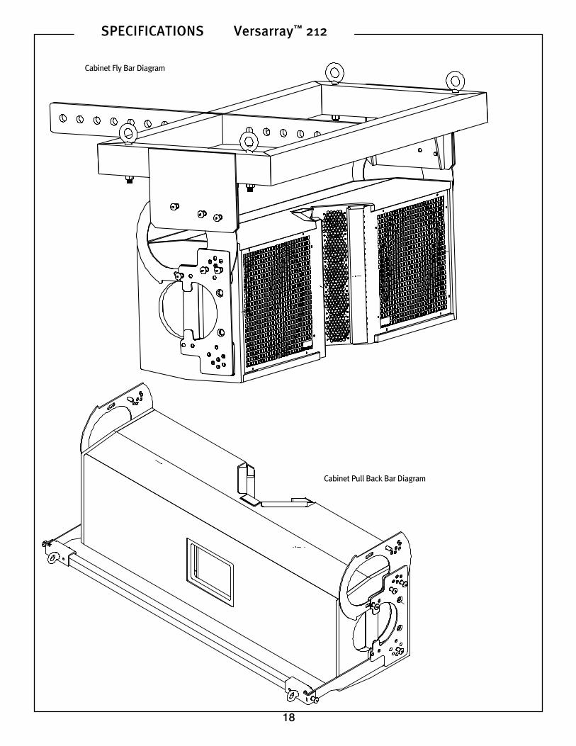
Cabinet Fly Bar Diagram
Cabinet Pull Back Bar Diagram

19
SPECIFICATIONS Versarray™ 212
Versarray™ 212 Cabinet Dimensions

20
SPECIFICATIONS Versarray™ 212
80305511Features and specifications are subject to change without notice.
Peavey Electronics Corporation • 5022 Hartley Peavey Drive • Meridian, MS 39305 • (601) 483-5365 • www.peavey.com©2009 Printed in the U.S.A. 03/09
Logo referenced in Directive 2002/96/EC Annex IV(OJ(L)37/38,13.02.03 and defined in EN 50419: 2005The bar is the symbol for marking of new waste and
is applied only to equipment manufactured after13 August 2005