specifying reactive system behavior - … · quately; one that addresses the concerns of the...
TRANSCRIPT
THÈSE NO 2588 (2002)
ÉCOLE POLYTECHNIQUE FÉDÉRALE DE LAUSANNE
PRÉSENTÉE À LA FACULTÉ INFORMATIQUE ET COMMUNICATIONS
POUR L'OBTENTION DU GRADE DE DOCTEUR ÈS SCIENCES
DANS LE DOMAINE INFORMATIQUE
PAR
B.Sc. with Honours I in Computer Science, University of Queensland, Brisbane, Australie
et de nationalité néo-zélandaise
acceptée sur proposition du jury:
Prof. A. Strohmeier, directeur de thèseProf. C. Atkinson, rapporteur
Prof. R. Keller, rapporteurProf. A. Wegmann, rapporteur
Lausanne, EPFL2002
SPECIFYING REACTIVE SYSTEM BEHAVIOR
Shane SENDALL


Abstract
Fundamentally, the development of software applications involves dealing with two distinctdomains: the real world and software domains; the two converge at the point where a soft-ware application is used to make an unsatisfactory real world situation into a satisfactoryone. Thus, software application development is a problem solving activity that assumes aproblem has been identified and a software application is desired to address this problem.
In this context, it is necessary to take measures that ensure the solution will be bothadequate and appropriate with respect to the problem. In particular, it is of utmost impor-tance that the problem in hand and the application’s role in helping to solve it are satisfacto-rily understood by the development team. If this condition is not observed then theapplication produced is doomed to be inadequate and/or inappropriate, independently of thecapabilities of the available technologies and resources, and also independently of otherwicked aspects of software development: constantly changing requirements, time-to-marketpressures, significant social, political, ethical or economic issues in the project, etc.
The principal objective of this thesis was to improve the state-of-the-art of specifica-tions that are used to communicate to the development team the behavior of the (future) sys-tem. In addressing this objective, this work initially involved defining the essentialrequirements of specifications that could ensure that the development team has a precise,correct and common understanding of the way the system is required to behave.
As a result of analyzing the identified requirements, two general kinds of specifica-tions were distinguished and perceived to be necessary to address the requirements ade-quately; one that addresses the concerns of the designers, providing a precise description ofthe system responsibilities; and one that addresses the concerns of the stakeholders in gen-eral, providing an informal description of the goals that the stakeholders have against thesystem. The first specification is referred to as the Behavioral Design Contract and the sec-ond one is referred to as the Behavioral Stakeholders Contract.
In this thesis, these two specifications were concretely realized as part of the ANZACapproach. The ANZAC approach defines two work artifacts called the ANZAC use casedescriptions and the ANZAC specification, which express the Behavioral StakeholdersContract and the Behavioral Design Contract, respectively. ANZAC use case descriptionsoffer an informal and usage-oriented description of the concordant goals that the stakehold-ers have against the system. An ANZAC specification offers a precise, operational descrip-tion of the system’s responsibilities in servicing all possible requests that it can receive overits lifetime; it uses a restricted subset of the Unified Modeling Language (UML) and itsObject Constraint Language (OCL).
In the ANZAC approach, the ANZAC use case descriptions are developed followingthe ANZAC use case framework. This framework defines the context, purpose, style andform of an ANZAC use case description, and it provides a goal-based approach to use case
i

Abstract
elicitation. Once a number of ANZAC use case descriptions are established, they can berefined to an ANZAC specification. This refinement procedure is (informally) defined bythe ANZAC mapping technique.
An ANZAC specification is developed by the description of three models, which eachexpress a different but complementary view of the system. These three models are called theConcept Model, the Operation Model, and the Protocol Model. The Concept Model definesan abstract system state space in terms of concepts from the problem domain, the OperationModel describes the effect of system operations on the system state, and the Protocol Modeldefines the correct behavior of the system in terms of its (allowable) input protocol.
As a “proof of concept”, this thesis demonstrates the ANZAC approach applied to anelevator control system, which is used to show how ANZAC offers a clean approach forcapturing the Behavioral Stakeholders and Design Contract. The elevator case study dem-onstrates the mapping between the Behavioral Stakeholders Contract and the BehavioralDesign Contract using the ANZAC mapping technique. It also highlights the difference inthe level of precision and formality that can be found between ANZAC use case descrip-tions and an ANZAC specification. Furthermore, it demonstrates some of the moreadvanced features of the ANZAC approach, in particular, its ability to specify performanceconstraints and concurrent behavior.
ii

Version Abrégée
Fondamentalement, le développement des applications logicielles implique deux domainesdistincts: le domaine du monde réel et le domaine du logiciel. Ces derniers convergent là oùune application logicielle est employée pour transformer une situation insatisfaisante dumonde réel en une situation satisfaisante. Ainsi, le développement d'applications logiciellesest une activité visant à résoudre des problèmes de réalisation considérant qu’un problème aété identifié et qu’une application logicielle est désirée pour répondre à ce problème.
Dans ce contexte, il est nécessaire de prendre des mesures qui assurent une solutionadéquate et appropriée au problème. En particulier, il est de la plus grande importance quele problème traité et le rôle de l'applications aidant à le résoudre soient compris par l'équipede développement d'une manière satisfaisante. Si cette condition n’est pas respectée, alorsl'application créée est condamnée à être inadéquate et/ou non appropriée, indépendammentdes capacités des technologies et des ressources disponibles, et aussi indépendamment desautres aspects ardus du développement de logiciel: le changement constant des besoins, lapression d’une mise sur le marché rapide, les issues sociales, politiques, morales ouéconomiques du projet, etc.
Ceci dit, cette thèse aborde deux défis qui doivent être relevés dans chaque projet dedéveloppement d'application logicielle. Premièrement, trouver un moyen approprié pourjustifier et négocier le rôle que l'application jouera dans la résolution du problème identifié.Et finalement, trouver un moyen approprié de communiquer cette connaissance aux mem-bres de l’équipe de développement qui sont chargés de trouver une solution logicielle, sousune forme qui leur est accessible et satisfasse leurs besoins comme concepteurs. Cette thèserapporte les moyens employés pour faire face au premier défi en tant que « stakeholderscontract », ainsi que les moyens employés pour faire face au second défi en tant que« design contract ». Dans ce contexte, cette thèse étudie des techniques et des approches quipeuvent être employées pour spécifier le comportement des systèmes réactifs et qui peuventêtre utilisées comme « stakeholders contract » et/ou « design contrat » sur le comportementdu système. (Dans la suite, nous nous référerons respectivement au « BSC » et au « BDC »).
Dans la première partie de cette thèse, un ensemble de critères qui définissent cer-taines qualités et caractéristiques souhaitables pour le « BSC » et le « BDC » sont donnés.En utilisant ces critères, quelques approches courantes s’accordant avec le thème de ce tra-vail sont examinées. L'analyse des diverses approches montre qu'il y a un certain nombre dedéficiences dans les approches actuelles pour répondre à ces critères. Ce résultat estemployé comme motivation pour établir une nouvelle approche, dont l'objectif estd'améliorer l'état actuel de la question à l'aide de langages et d’outils communément utilisé.Par conséquent, le reste de la thèse est consacré à l'établissement de cette approche, appelléeANZAC.
iii

Version Abrégée
L'approche ANZAC utilise des langages et des outils courants, mais également beau-coup de techniques bien établies de technologie de programmation, telles que pré- et post-conditions, et des principes, tels que la séparation des intérêts. Elle répond aussi bien au« BSC » qu’au « BDC » pour ce qui est de l’importance de les traiter les deux de manièreunifiée, suggérant une approche simple. Cependant, en raison des intérêts distincts liés àchacun des deux contrats, deux objets de travail séparés sont employés par ANZAC (unpour chaque contrat). ANZAC définit un procédé systématique, appelé la technique de cor-rélation ANZAC, pour obtenir le « BDC » à partir du « BSC ». Ceci favorise le tracabilitéentre les deux contrats et établit une corrélation informelle entre eux.
L'aspect d’ANZAC décrivant le « BSC » est défini par les « use cases ». Le cadre pro-posé est une spécialisation (et clarification) des travaux sur les « use cases ». Le modèled'ANZAC décrivant le « BDC » est défini en utilisant un sous-ensemble restreint du« Unified Modeling Language » (UML) et de son « Object Constraint Language » (OCL).Cette spécification ANZAC décrit le comportement du système respectif en utilisant unmodèle qui offre trois vues complémentaires. Chaque vue capture un aspect distinct dusystème: état, opération et activité.
La dernière partie de cette thèse montre ANZAC appliqué à une étude de cas d'unsystème de contrôle d'ascenseur. Elle permet de valider l'approche et montre à quel pointANZAC offre une approche propre, concise et précise pour capturer les « BSC » et les« BDC ». L'étude de cas de l’ascenseur démontre la corrélation entre les « BSC » et les« BDC » utilisant la technique de corrélation ANZAC. Elle met également en évidence ladifférence au niveau de la précision qui peut exister entre les deux contrats. En outre, elledémontre certaines des caractéristiques les plus avancées d’ANZAC, en particulier sacapacité à décrire des contraintes de performance et les comportements concurrents.
iv

Acknowledgements
There are a number of people that have contributed in various ways to my work over theyears. I would like to express my gratitude to them.
First of all, I would like to thank Alfred Strohmeier for supervising my work and forintroducing me to the work area addressed by this thesis. In particular, he motivated me tolook into specifying concurrency and synchronization requirements as part of softwareinception activities, which I now believe to be a very interesting (and surprisingly under-explored) area of research. He also encouraged me and made it possible to go to numerousinternational conferences. Furthermore, his comments greatly improved the quality of thework that is presented in this document. In particular, the Operation Schema notation pro-posed in this thesis was much more homogeneous thanks to his vast experience in (pro-gramming) language design. I would also like to thank him for much “fatherly” advice thathe has given to me over the years.
Second, I would like to thank all the jury members Colin Atkinson, Rudolf Keller, andAlain Wegmann for having taken the time and effort to review my thesis and to serve on myexamination board. Their comments have improved the quality of the final manuscript.
Third, I am greatly indebted to Jörg Kienzle. His review of this thesis not onlyremoved many typographical and grammatical errors, but also his conscientious commentswere extremely constructive and have improved the quality of this thesis. He was also verykind in providing me with his thesis template, which certainly saved me some initial “star-tup” effort, and I would also like to thank him for some useful comments on my defensepresentation. Also, I would like to thank my “roomie” and the “next-in-line” MohamedKandé for making my time at the lab more fun and pleasant and for providing a spring-board for bouncing ideas and problems off. I would also like to thank him for some goodcomments on the introduction of this document and on my defense presentation. Also, Iwould like to thank the many students that I had the pleasure to work closely with MarcosPerez Jurado, Slavisa Markovic, Ankur Gupta, Mahim Mishra, Milena Ilic, Rida Hamdan,and Marco Bonetti. I would like to thank Didier Buchs for helping me with the Frenchabstract and some sticky areas of semantics in Operation Schemas. And, I would like tothank the other members of the Software Engineering Laboratory (LGL), Anne CrettazSchlageter, Benjamin Barras, Raul Silaghi, David Hürzeler, Stanislav Chachkov, AdelBesrour, Xavier Caron, Sandro Costa, Rodrigo Garcia-Garcia, and Juan-Miguel Gomez foran enjoyable atmosphere at the lab. I would also like to thank past members who made quitesome effort to welcome me and who assisted me in early times Thomas Wolf, Stéphane Bar-bey, Enzo Grigio, Nicolas Guelfi, Mathieu Buffo, Cécile Peraire, Giovanna Di Marzo andGabriel Eckert. Also, I would like to thank the EPFL computer science third year studentsof the past three years, they taught me many things about making Operation Schemas usableand learnable.
v

Fourth, J’aimerais remercier mes beau-parents suisses Gérald et Marie-FrançoiseMüller pour leur soutien inconditionnel et pour m’avior accepté instantanément commemembre de leur famille depuis Nöel 1997.
Fifth, I would like to thank my parents Wayne and Wendy and my sister Debi. Theyhave been a constant support to me right from when my ideas were not oriented towardscomputers. They have themselves made many sacrifices for my sake, and they acceptedwithout question my crazy plans of doing my doctorate on the other side of the world inSwitzerland. In particular, I am sure that I would have not taken this task on without the sup-port and encouragement of my father. Many a time I reminisce on the good ol’ days. It isprobably best put in the words of (the late) Douglas Adams: “In those days, spirits werebrave, the stakes were high, men were REAL men, women were REAL women, and smallfurry creatures from Alpha Centauri were REAL small furry creatures from Alpha Cen-tauri.”
Sixth, I would also like to thank my wife Fabienne. She has been a tremendous sup-port both physically and mentally, and she has kept me company through the good and notso good days. She has always been there for me and she has made my world that much morehappier. I look forward to spending the rest of my days with her hand-in-hand.
Finally, how can I begin to thank the big J for what he did a couple of thousand yearsago and continues to do today. He gives me endless inspiration and he never ceases toamaze me with his love. What can I say other than Hallelujah!

Table of Contents
Table of Contents
Abstract .................................................................................................................. i
Version Abrégée..................................................................................................... iii
Acknowledgements ................................................................................................ v
Table of Contents ................................................................................................... vii
List of Figures ........................................................................................................ xv
1 Introduction ..................................................................................................... 11.1 Setting the Scene........................................................................................... 11.2 General Approach and Focus........................................................................ 21.3 Influences ...................................................................................................... 41.4 Scope............................................................................................................. 61.5 Contributions................................................................................................. 71.6 Plan ............................................................................................................... 9
2 Key Concepts and Related Work .............................................................. 112.1 Key Concepts ................................................................................................ 11
2.1.1 Abstraction, Decomposition, Projection and Precision .................. 112.1.2 Inherent Concurrency ..................................................................... 122.1.3 Correctness...................................................................................... 12
2.2 Related Work ................................................................................................ 142.2.1 The Unified Modeling Language.................................................... 142.2.2 Fusion.............................................................................................. 162.2.3 Use Cases........................................................................................ 192.2.4 Catalysis.......................................................................................... 222.2.5 Pre- and Postconditions .................................................................. 232.2.6 Model-Based Formal Specifications............................................... 242.2.7 Rely- and Guarantee-Conditions .................................................... 27
3 Specifying the Behavioral Stakeholders Contract ............................... 293.1 Introduction................................................................................................... 293.2 Background on Use Cases ............................................................................ 303.3 Contexts and Purposes for which Use Cases are Applied ............................ 32
3.3.1 Possible Contexts and Purposes for Applying Use Cases .............. 323.3.2 The Context and Purpose for Applying Use Cases in this Work.... 33
3.4 Defining Use Cases....................................................................................... 343.4.1 Jacobson’s & UML’s Definition of a Use Case ............................. 34
vii

Table of Contents
3.4.2 Defining Actor ................................................................................ 353.4.3 Exploring Actions ........................................................................... 373.4.4 Cockburn’s Definition of a Use Case ............................................. 373.4.5 Understanding Goals, Interactions and System Responsibilities.... 38
3.4.5.1 Relating Goals to Interaction................................................. 383.4.5.2 Problem-Grounded Goals of Stakeholders............................ 40
3.4.6 ANZAC’s Definition of a Use Case ............................................... 413.5 Construction of Use Cases by Eliciting Actor Goals.................................... 42
3.5.1 Representing Use Case Relationships............................................. 433.5.2 Stakeholder Goal Levels................................................................. 443.5.3 Difficulties in Goal Elicitation........................................................ 453.5.4 Defensive Goals.............................................................................. 45
3.6 Categories and Personalities of Actors and Stakeholders............................. 463.6.1 Scoping Secondary Actors.............................................................. 47
3.7 Tying Use Cases to Extra-Functional Requirements and Project Constraints ........................................................................................ 48
3.8 Managing Change in Use Cases ................................................................... 493.8.1 Reducing the Effects of Change ..................................................... 49
3.8.1.1 Relationship of Use Cases to User Interface and Design Details ....................................................................... 49
3.9 Use Case Descriptions .................................................................................. 503.9.1 Representation for Use Case Descriptions...................................... 513.9.2 An Example of a Use Case ............................................................. 533.9.3 Granularity of Use Case Steps ........................................................ 56
3.10 Summary of the ANZAC Use Case Framework........................................... 583.11 Deficiencies of ANZAC Use Case Descriptions .......................................... 60
3.11.1 Making use of Use Cases in other Development Activities ........... 62
4 Specifying the Behavioral Design Contract ........................................... 634.1 Introduction................................................................................................... 634.2 Wanted: Behavioral Design Contract ........................................................... 644.3 ANZAC Specification................................................................................... 68
4.3.1 Three Views of the System............................................................. 684.3.2 Concept Model................................................................................ 694.3.3 Operation Model ............................................................................. 714.3.4 Protocol Model ............................................................................... 734.3.5 Communications between System and Actors................................ 754.3.6 System Reaction ............................................................................. 76
4.4 ANZAC Mapping Technique ....................................................................... 76
viii

Table of Contents
5 Concept Model.................................................................................................. 795.1 Introduction................................................................................................... 795.2 The Notation of Concept Models.................................................................. 80
5.2.1 Describing the Concept Model with UML ..................................... 805.2.2 Graphical Notation for Concept Models......................................... 825.2.3 Constraints ...................................................................................... 86
5.2.3.1 Multiplicities ......................................................................... 875.2.3.1 OCL Invariants ...................................................................... 87
5.3 Describing Concept Models.......................................................................... 885.4 An Example of a Concept Model.................................................................. 88
5.4.1 Invariants for the Strategic Conquest System................................. 915.5 Relating the Concept Model to Design Artifacts .......................................... 92
6 Operation Model.............................................................................................. 956.1 Introduction................................................................................................... 956.2 Pre- and Postconditions in Operation Schemas ............................................ 966.3 Language for Writing Pre- and Postconditions in
Operation Schemas ....................................................................................... 986.3.1 Writing Pre- and Postconditions in OCL........................................ 99
6.4 The Form of an Operation Schema............................................................... 1016.4.1 Operation Schema Form and Structure........................................... 101
6.4.1.1 Operation Clause ................................................................... 1016.4.1.2 Description Clause ................................................................ 1026.4.1.3 Notes Clause.......................................................................... 1026.4.1.4 Use Cases Clause................................................................... 1026.4.1.5 Scope Clause ......................................................................... 1026.4.1.6 Messages Clause.................................................................... 1036.4.1.7 New Clause............................................................................ 1036.4.1.8 Aliases Clause ....................................................................... 1046.4.1.9 Pre Clause.............................................................................. 1056.4.1.10 Post Clause ........................................................................... 106
6.4.2 Rules Governing Consistency Between Clauses ............................ 1076.5 Operation Schemas: Constructs, Rules, Assumptions,
and Interpretations ........................................................................................ 1086.5.1 Asserting Creation and Deletion in Operation Schemas ................ 1096.5.2 Consistency of Associations ........................................................... 1106.5.3 Frame Assumption.......................................................................... 1116.5.4 Incremental Descriptions ................................................................ 113
6.5.4.1 Minimum Set Principle ......................................................... 1156.5.4.2 Incremental Plus and Minus .................................................. 117
ix

Table of Contents
6.5.5 Shorthands and Additional Language Constructs........................... 1186.6 Reusing Parts and Reducing the Size of Operation Schemas
by Functions and Parameterized Predicates.................................................. 1226.6.1 Parameterized Predicate.................................................................. 1236.6.2 Function .......................................................................................... 125
6.7 Messages ....................................................................................................... 1276.7.1 Role of Messages ............................................................................ 1276.7.2 Message Semantics ......................................................................... 1276.7.3 Output Message Queue................................................................... 1286.7.4 Message Sending ............................................................................ 128
6.7.4.1 Asserting Message Sending in the Post clause...................... 1296.7.4.2 Shorthands for Message Sending Assertions ........................ 1296.7.4.3 Predefined Identifier: sender ................................................. 132
6.7.5 Message Kinds................................................................................ 1326.8 Synchronous Communication, Results Returned by
Operations, and Exceptions .......................................................................... 1346.8.1 Calls ................................................................................................ 1356.8.2 Exceptions From Synchronous Calls.............................................. 137
6.9 Concurrent Operation Execution .................................................................. 1406.9.1 Problems in Specifying Concurrent Operations with
Operation Schemas ......................................................................... 1406.9.2 Operation Schemas for Specifying Concurrent Operations............ 142
6.9.2.1 Granularity of Serialization ................................................... 1436.9.2.2 Shared Clause ........................................................................ 1436.9.2.3 Shared Resources .................................................................. 1446.9.2.4 Usage of Decorators .............................................................. 1466.9.2.5 Multiple Snapshots of the Value of a Resource .................... 1476.9.2.6 Incremental Descriptions....................................................... 1506.9.2.7 If-Then-Else Expressions ...................................................... 1516.9.2.8 Rely Expressions ................................................................... 1566.9.2.9 Atomicity of Effects .............................................................. 1626.9.2.10 Shorthands and Parameterized Predicates that Use
Shared Resources ................................................................. 1656.9.3 Issues and Remarks......................................................................... 166
6.10 Example of an Operation Schema................................................................. 1676.10.1 Background..................................................................................... 1676.10.2 Concept Model for AuctionManager System ................................. 1686.10.3 Operation Schema for placeBid Operation..................................... 170
x

Table of Contents
7 Protocol Model ................................................................................................. 1757.1 Introduction................................................................................................... 1757.2 Concepts and Basic Model Elements of a Protocol Model........................... 1767.3 Notation and Semantics of Protocol Models ................................................ 178
7.3.1 Transitions ...................................................................................... 1787.3.2 Composite States............................................................................. 179
7.3.2.1 Sequential States.................................................................... 1807.3.2.2 Concurrent States .................................................................. 1807.3.2.3 Real Concurrency and UML Concurrent States.................... 1817.3.2.4 Transitions into and out of Composite States........................ 1827.3.2.5 Auto-Concurrent States ......................................................... 1837.3.2.6 UML and Auto-Concurrent States ........................................ 185
7.4 Specifying and Interpreting Protocol Models ............................................... 1867.4.1 Matching Events to Operations....................................................... 1867.4.2 Guards............................................................................................. 1877.4.3 Specifying Temporal Ordering of Events....................................... 189
7.4.3.1 Event Sequences.................................................................... 1897.4.4 Concurrency.................................................................................... 1897.4.5 Orthogonality .................................................................................. 1917.4.6 Auto-Concurrent Activities............................................................. 1927.4.7 Auto-Orthogonal Activities ............................................................ 1937.4.8 Divide-by-Actor Technique............................................................ 1947.4.9 Synchronization between Regions of Different Concurrent States 1957.4.10 Divide-By-Collaboration Technique .............................................. 196
7.4.10.1 Use Case View-States .......................................................... 1987.4.11 Event Delivery for Concurrent States............................................. 1987.4.12 Protocol Model Consistency........................................................... 199
7.5 Specifying Internally-Triggered Actions and Timing Constraints ............... 1997.5.1 Internally-Triggered Actions .......................................................... 199
7.5.1.1 Change and Time Events....................................................... 1997.5.2 Timing Constraints ......................................................................... 201
7.5.2.1 Time-Based Properties .......................................................... 2017.5.2.2 Using Navigation Expressions in Timing Constraints .......... 2027.5.2.3 Invariants ............................................................................... 2037.5.2.4 Guards ................................................................................... 205
7.6 Protocol Model Example .............................................................................. 205
8 ANZAC Mapping Technique ...................................................................... 2098.1 Introduction................................................................................................... 2098.2 Relating the ANZAC Use Case Descriptions to the ANZAC Specification 210
xi

Table of Contents
8.2.1 Noteworthy Characteristics of ANZAC Use Case Descriptions .... 2108.2.2 Noteworthy Characteristics of an ANZAC Specification............... 2108.2.3 Relating the Use Case Descriptions to Each Model of the
ANZAC Specification..................................................................... 2108.2.4 Benefits of Relating ANZAC Use Case Descriptions to an
ANZAC Specification..................................................................... 2118.3 ANZAC Mapping Technique ....................................................................... 212
8.3.1 ANZAC Mapping Technique Step by Step .................................... 212
9 Elevator Case Study ....................................................................................... 2219.1 Introduction................................................................................................... 221
9.1.1 Problem Statement for the ElevatorControl system ....................... 2219.2 ANZAC Use Case Descriptions.................................................................... 2229.3 ANZAC Specification................................................................................... 226
9.3.1 Concept Model................................................................................ 2279.3.2 Applying Step 1 of the ANZAC Mapping Technique.................... 2299.3.3 Applying Step 2 of the ANZAC Mapping Technique.................... 2349.3.4 Applying Step 3 of the ANZAC Mapping Technique.................... 2349.3.5 Applying Step 4 of the ANZAC Mapping Technique.................... 2429.3.6 Applying Step 5 of the ANZAC Mapping Technique.................... 248
9.4 Addressing Concurrent Behavior in the ElevatorControl System ................ 2499.4.1 Protocol Model (Revised Version) ................................................. 2499.4.2 Operation Model (Concurrent Version).......................................... 251
9.5 Remarks ........................................................................................................ 257
10 Conclusion.......................................................................................................... 25910.1 Summary ....................................................................................................... 259
10.1.1 Realization of the Two Contracts ................................................... 26010.2 Critical Review ............................................................................................. 262
10.2.1 Advantages...................................................................................... 26210.2.2 Remaining Problems and Limitations............................................. 262
10.3 Future Work .................................................................................................. 26310.4 Final Remarks ............................................................................................... 265
Bibliography ...................................................................................................... 267
A Object Constraint Language ....................................................................... 283
B Tool Support ..................................................................................................... 293
C Parameterized Predicates and Functions ............................................... 303
Curriculum Vitae .................................................................................................... 307
xii
List of Figures
List of Figures
Chapter 1: Introduction
Chapter 2: Key Concepts and Related Work
Chapter 3: Specifying the Behavioral Stakeholders ContractFigure 3.1: Goal Hierarchy ................................................................................ 43Figure 3.2: Use Case Format ............................................................................. 53Figure 3.3: Buy Items Use Case ........................................................................ 55Figure 3.4: Check-Out Shopping Cart Use Case ............................................... 57
Chapter 4: Specifying the Behavioral Design Contract
Chapter 5: Concept ModelFigure 5.1: Graphic Notation for Class, Enumeration, and Data Type ............. 83Figure 5.2: Diagrammatic Notation for Associations in the Concept Model .... 84Figure 5.3: Diagrammatic Notation for Generalization in the Concept Model . 85Figure 5.4: Diagrammatic Notation for the System Class in the
Concept Model ................................................................................ 86Figure 5.5: An Association between Customer and Client (a rep class) ........... 86Figure 5.6: Association between the classes Organization and Person ............. 87Figure 5.7: Concept Model for Strategic Conquest Application ....................... 90
Chapter 6: Operation ModelFigure 6.1: Concept Model for LotteryTicketManager ..................................... 100Figure 6.2: Alternatives for returning results from operations .......................... 134Figure 6.3: Call with two exceptions ................................................................. 135Figure 6.4: CarManager Concept Model ........................................................... 141Figure 6.5: Operation Schemas for adding cars in the CarManager system...... 142Figure 6.6: Concept Model for AuctionManager system .................................. 169Figure 6.7: Operation Schema for placeBid ...................................................... 171
Chapter 7: Protocol ModelFigure 7.1: Four examples of transitions ........................................................... 179Figure 7.2: Example of a sequential state .......................................................... 180Figure 7.3: Example of a concurrent state in UML (with two regions)............. 181Figure 7.4: Example of a concurrent state for Protocol Models ........................ 182Figure 7.5: Example of transitions into and out of a composite state................ 182Figure 7.6: Example of auto-concurrent state (LHS) and
its expanded form (RHS)................................................................. 184Figure 7.7: Example of auto-concurrent state with multiplicity range .............. 185
xv

List of Figures
Figure 7.8: Example of a direct event/operation match on a transition............. 186Figure 7.9: Example of a different event/operation transition pair.................... 186Figure 7.10: Examples of guards ......................................................................... 187Figure 7.11: Examples of guards written in OCL................................................ 188Figure 7.12: Example of guard-less transitions ................................................... 188Figure 7.13: Example of a sequencing constraint between two events ............... 189Figure 7.14: Example of specifying inherent concurrency.................................. 190Figure 7.15: Concurrent state that does not conform to
inherent concurrency guideline ....................................................... 191Figure 7.16: Example of specifying orthogonal transitions with
an orthogonal state .......................................................................... 192Figure 7.17: Example of explicitly specifying all possible states using
a sequential state.............................................................................. 192Figure 7.18: Example of an auto-concurrent state ............................................... 193Figure 7.19: Example of auto-orthogonal activity specified by
an auto-orthogonal state .................................................................. 194Figure 7.20: Protocol Model for the system SystemW........................................ 195Figure 7.21: Example of synchronization between concurrent states ................. 196Figure 7.22: Example of Factory Activity for Production System...................... 197Figure 7.23: Example of a View on Production System...................................... 198Figure 7.24: Example of change (when) and time (after) events......................... 201Figure 7.25: Protocol Model for System1 ........................................................... 203Figure 7.26: Overview of input messages for the system VirtualRoulette .......... 206Figure 7.27: Auto-concurrent client activity for VirtualRoulette ........................ 206Figure 7.28: Revised Betting State: adds synchronization with
GameOfficial actor .......................................................................... 207Figure 7.29: Auto-concurrent game official activity for VirtualRoulette............ 207Figure 7.30: Auto-concurrent game table view activity for VirtualRoulette....... 208Figure 7.31: Protocol Model for VirtualRoulette ................................................ 208
Chapter 8: ANZAC Mapping Technique
Chapter 9: Elevator Case StudyFigure 9.1: Take Elevator use case for ElevatorControl system........................ 223Figure 9.2: Enter Cabin use case for ElevatorControl system........................... 224Figure 9.3: Exit Cabin use case for ElevatorControl system............................. 226Figure 9.4: Concept Model for ElevatorControl system.................................... 228Figure 9.5: Annotated Enter Cabin use case for ElevatorControl system ......... 231Figure 9.6: Annotated Exit Cabin use case for ElevatorControl system ........... 233Figure 9.7: Overview of all input and output messages for
ElevatorControl System .................................................................. 233
xvi

List of Figures
Figure 9.8: Activities for each actor of the ElevatorControl system ................. 235Figure 9.9: View of protocol described by Enter Cabin use case...................... 237Figure 9.10: View of protocol described by Exit Cabin use case........................ 238Figure 9.11: CabMovementAndDoorStateView (Version 1) .............................. 239Figure 9.12: ElevatorControl’s Protocol Model .................................................. 240Figure 9.13: Operation Schema for floorRequest ................................................ 243Figure 9.14: Operation Schema for changeFloor................................................. 245Figure 9.15: Operation Schema for stopForRequest ........................................... 246Figure 9.16: Operation Schema for openForRequest .......................................... 247Figure 9.17: Operation Schema for serviceNextRequest..................................... 248Figure 9.18: CabMovementAndDoorStateView (revised version) ..................... 250Figure 9.19: Operation Schema for floorRequest (concurrent version) .............. 252Figure 9.20: Operation Schema for decideOnStop (concurrent version) ............ 254Figure 9.21: Operation Schema for openForRequest (concurrent version)......... 255Figure 9.22: Operation Schema for serviceNextRequest (concurrent version) ... 256Figure 9.23: Sequence diagram showing interleaving of operation executions .. 257
Chapter 10: ConclusionFigure 10.1: Overview of the ANZAC use case descriptions and
the ANZAC specification................................................................ 261
Bibliography
Appendix A: Object Constraint LanguageFigure A.1: Example UML Class Diagram ........................................................ 284
Appendix B: Tool Support
Appendix C: Parameterized Predicates and Functions
xvii

List of Figures
xviii

Chapter 1:
Introduction
≈The hardest single part of building a software system isdeciding precisely what to build. No other part of the con-ceptual work is so difficult as establishing the detailed tech-nical requirements.∆ Frederick P. Brooks, Jr. [Bro95]
1.1 Setting the Scene
Nowadays, software-intensive systems play a role in almost all areas of our life, profes-sional and private—a coverage that continues to expand as new possibilities for applyingsoftware solutions are explored and technologies for interoperation of systems areimproved. Software applications have become the primary interface to services provided byvast networks of systems. However, in spite of our reliance and inevitable dependence onsoftware, it too often falls short of the purpose for which it was intended or functions inunexpected ways [Pre99].
Fundamentally, the development of software applications involves dealing with twodistinct domains: the real world and software domains1; the two converge at the point wherea software application is used to make an unsatisfactory real world situation into a satisfac-tory one. Thus, software application development is a problem solving activity that assumesa problem has been identified and a software application is desired to address this problem.This activity is a very difficult task to master in general, where Brook’s four properties of
1. referred to as the machine and the world by Jackson [Jack95]
1

General Approach and Focus
the “irreducible essence of modern software systems”: complexity, conformity, changeabil-ity and invisibility [Bro87], highlight some of the variables at play in this task.
In this context, it is necessary to take measures that ensure the solution will be bothadequate and appropriate with respect to the problem. In particular, it is of utmost impor-tance that the problem in hand and the application’s role in helping to solve it are satisfacto-rily understood by the development team. If this condition is not observed then theapplication produced is doomed to be inadequate and/or inappropriate, independently of thecapabilities of the available technologies and resources, and also independently of otherwicked aspects of software development, such as, constantly changing requirements, time-to-market pressures, significant social, political, ethical or economic issues in the project,etc.
In other words, a principal challenge that must be faced in each and every softwareproject is to ensure that the development team has a precise, complete, correct and commonunderstanding of what they should build. This challenge is the theme of this thesis.
1.2 General Approach and Focus
The approach that I take in this thesis is based upon the assumption that the informationabout what system should be built is formally communicated to the development team as aspecification. The reason for this assumption is that a specification allows every member ofthe development team to have a common statement of what to build and it is a resource thatcan be revisited when necessary.
The approach of this thesis refers to the above mentioned specification as the DesignContract—since it represents the contract on design correctness that must be observed bythe development team. I now introduce a number of characteristics and qualities that aredesirable for a Design Contract to possess.
Firstly, a Design Contract should explicitly describe the interface between the systemand its environment, otherwise it would be unsure exactly which responsibilities are thoseof the system versus those of the environment (and there would be no way to decide whetherthe system has been overspecified by the Design Contract). This is particularly importantfor systems that have strong constraints imposed on them by their environment—which isoften the case for reactive systems. Also, the system is evaluated with respect to its usage inits environment. Therefore, a Design Contract that clearly defines the interface between thesystem and its environment would provide a basis for validating the system’s role in thatenvironment.
Secondly, the desire to build an appropriate system suggests that it is not only essen-tial to construct a specification for designers to follow, but also to provide a justification ofthat specification [Smi96]. A justification for a Design Contract entails making sure thateach constraint that it places on the design of the system is aligned with and traceable to the
2
(system-related) goals of the various parties that have a vested interest in the software appli-cation. These parties are commonly referred to as the stakeholders of the system.
Lastly, and probably most obviously, the Design Contract should be given in a formthat is accessible to the developers and it should provide all the information needed todesign the system and no more, hence no under- or over-specification [Par72, McD94]. Inother words, the Design Contract should facilitate the job of designers. An overspecifiedDesign Contract implies that it expresses premature design decisions1, which would mean itwould need to be modified as these decisions change—an undesirable situation. Whereas,an underspecified Design Contract means that the designers do not have sufficient informa-tion to be autonomous, degrading its usefulness as the contract on design. Thus, a DesignContract that provides strictly only the essential information permits designers to producecreative and innovative solutions that may not have been initially envisaged, but that stillmeet the requirements of the stakeholders.
In review of these desired characteristics of a Design Contract, the second one sug-gests that a Design Contract can not be constructed without considering the goals of thestakeholders for the system. It is unlikely however that the Design Contract should explic-itly describe the stakeholders’ goals for the system, because much of the contextual infor-mation that is necessary to describe a goal is at least superfluous from the perspective of thedesigners. In some cases, such information would cause confusion during design, because itdescribes situations that cannot be detected or acted upon by the system. And, such informa-tion can make it difficult for designers to know whether the system should or should notprovide a means to deal with the situation. Therefore, explicitly describing the stakeholders’goals would conflict in general with the objective for a “designer-friendly” Design Contract,which is the third (desired) characteristic.
This apparent divergence between the second and third characteristics reveals two dis-parate requirements on the Design Contract: provide a valid description of the stakeholders’goals against the system, and provide a precise and focused description of the system todesign. The approach taken in this work to address these two different requirementsinvolved defining another specification that explicitly captures the concordant goals that thestakeholders have against the system. I refer to this specification as the Stakeholders Con-tract, since it signifies a contractual agreement2 between stakeholders.
By addressing the requirements (driven by the desired characteristics) with two differ-ent specifications, it is necessary to ensure that they can be nevertheless coherently com-bined to fulfill the overall objective of communicating the system to build to thedevelopment team. Such a relationship suggests an explicit bridge between them. Furthermotivation for an explicit relationship between the two specification comes from the desire
1. “For every complex problem, there is a solution that is simple, neat, and wrong.” -- H. L. Mencken2. In this context, the term ‘contract’ can mean anything from a very informal agreement to a full-blown
formal agreement that is bound by law.
3

Influences
to ensure that the Design Contract is justified with respect to the interests of stakeholders(derived from the second characteristic). In this respect, the Stakeholders Contract is used toestablish the Design Contract, where the Stakeholders Contract is refined into the DesignContract and traceability is set up between the stakeholders’ goals described by the Stake-holders Contract and the system responsibilities described by the Design Contract.
Rather than aiming at facilitating the job of the designers, like the Design Contract,the aim of the Stakeholders Contract is to facilitate the job of stakeholders in understanding,negotiating and agreeing upon the (software) system requirements. By focusing on goals,one can have a greater confidence that the Stakeholders Contract adequately and appropri-ately captures the requirements. Ideally, the Stakeholders Contract should be in a form thatis accessible to all stakeholders, both technical and non-technical alike, which means that noassumptions can be made about the (technical) background of stakeholders: it must allowfor the “lowest common denominator”. Also, the Stakeholders Contract should allow one tocapture the subtleties and complexities of the informal real world, since this activity consid-ers the real world domain and not only the software domain.
Classically speaking, the Stakeholders and Design Contracts can be thought of as partof the Software Requirements Specification [TD97] for a project. However, a SoftwareRequirements Specification generally includes additional information, e.g., project con-straints, project drivers, assumptions, (social, political, ethical, economic and technical)issues, etc.
The focus of this thesis is on the Stakeholders and Design Contracts. In addition toestablishing a suitable formalism for the Stakeholders and Design Contracts, the approachtaken in this thesis determines a bridge between the two specifications, which ensures thatrefinement and interplay is possible between them.
1.3 Influences
The development of an application can be logically viewed as being made up of many stepstaking one from vision to realization; this is essentially the process of stepwise refinement[Wir71]. However, as is well-documented (e.g. [WK00, Pre97]), there is an interplaybetween the different steps that take one from concept to implementation. The concern forfeedback, incremental delivery, and parallel work during the development process, origi-nally highlighted by Boehm’s spiral model [Boe86], suggests that the development processas a whole is not simply a one-way refinement.
One factor that suggests the activity of defining the Stakeholders and Design Con-tracts is intertwined with other software development activities is problem complexity. Atthe heart of this complexity is: size of the problem, complexity of the system’s environment,and complexity in communication among the stakeholders. In what follows, I refer to theStakeholders and Design Contracts as “the specifications” to be concise.
4

• Size of the problem: The size of the problem that is to be addressed by the systemaffects the way and ease with which a team gathers, analyzes and manages informa-tion about it. In general, the larger the amount of information, the more difficult it is tokeep the specifications consistent, concise and up-to-date, and the more likely thatthey will evolve along with the project as issues are clarified en route.
• Complexity of the system’s environment: A system is often constrained to interact withits environment in a certain way and within certain rules and expectations. Due to thepossible complexity of these constraints, it may be necessary, and even more produc-tive, to allow the specifications to evolve as these constraints are better understood.
• Complexity in communication among the stakeholders: Software systems may have alarge number of stakeholders, who can have different backgrounds, roles, domainknowledge, technical competencies, and agendas. As a consequence, stakeholderswill often have different objectives and perceptions of the problem domain that lead toconflicts of interests between them. In such cases, it may not be possible to resolve allconflicts upfront. It may be necessary to instead experiment with different realizationsto convince stakeholders one way or the other, requiring the specifications to beupdated as the conflicts are resolved.
Project dynamism is another factor that can drive an iterative and incremental developmentof the two specifications. At the heart of this factor is: requirements instability, time-to-mar-ket pressures, and uncertainty of which system to build.
• Requirements instability: in addition to changes made to requirements for technicalreasons, the requirements may evolve over time due to changes in the client’s per-ceived needs or changes to the constraints on the project that are driven by externalinfluences. This means that as requirements are changed, the specifications will needto be brought up-to-date.
• Time-to-market pressures: competition in the business world can mean that the win-dow of opportunity is all important. In such cases, a project can be given a shortperiod of time within which to produce the software. Consequently, only features thatmake the current release are specified before design and implementation activities areundertaken [BLP+01]. In such cases, the specifications will only provide a descriptionof partial system capability.
• Uncertainty in which system to build: the details of all the requirements may not beknown or well understood initially, e.g., the product may be used to explore a newmarket. In such cases, it may be desirable to allow the specifications to evolve as theproblem is better understood, where the choices made during design and implementa-tion affects what can be judged to be a satisfactory future situation for the system (andfor the endeavor of the stakeholders).
5

Scope
In consideration of the above points, it would seem necessary to ensure that the Stakehold-ers and Design Contracts are malleable to change, facilitate the synchronization of changesbetween them, and offer support for incremental description.
1.4 Scope
As the title implies, this work is about “Specifying Reactive System Behavior”. Hence, it isnecessary to narrow the scope on the context given in the previous sections, which liessomewhere within the broad area of “Requirements & Analysis” (using the terms of theclassical development lifecycle model1).
• Reactive Systems
I consider only software systems that are reactive in nature. This means that the sys-tem interacts with its environment over time in an organized manner, where stimuli arrive in an endless and perhaps unexpected order [HP85]. The correct treatment of these stimuli means that a reactive system must “know” whether it is in an appropriate situation to serve the requests and notifications that are implied by the stimuli.
In terms of classification, reactive systems exclude data-intensive systems, such as, data management systems, and they exclude transformational systems, where all input is given at one time or as a continuous stream, e.g., compilers, batch processes, media stream filters, numerical mathematics applications, etc. A large percentage of distrib-uted systems, and particularly internet-based systems, are reactive in nature. This cov-ers many business systems, since they need to be able to react to requests in a timely manner and in an endless cycle.
Reactive systems often must deal with an inherently concurrent environment, i.e., they must deal with stimuli from different sources at the same time, and they often have timeliness requirements (e.g., real-time systems are subject to strong performance constraints). Due to its interactive nature, a reactive system is bound to its environ-ment (e.g., embedded systems are ruled by strong hardware constraints).
• Behavioral Specification
I focus on specifications that capture at most the behavioral aspects of the Stakehold-ers and Design Contracts. This means that I investigate only specifications that involve functional requirements and some extra-functional requirements, such as, tim-ing constraints and concurrency. As I do not address the complete Stakeholders and Design Contracts, I refer to the aspect addressed in this thesis as the Behavioral Stake-holders Contract and the Behavioral Design Contract, respectively. Having said that, the “Behavioral” label does not tell the full story: I do not address all kinds of extra-functional requirements that constrain the behavior of the system, such as, security requirements, usability requirements, etc. [RR00]
1. Requirements & Analysis, Architecture & Design, Implementation, and Testing.
6

• Mainstream Languages and Tools
One of the main objectives of this thesis was to ensure that all proposals made could be realized using mainstream languages and tools. The reason is simple: this work is concerned with software development, and therefore the link to software development practice should be clear.
The techniques investigated in this thesis are principally model-based. The reason for a bias towards model-based languages is because models naturally support abstrac-tion, projection, and decomposition. And I believe that in trying to understand what needs to be built, these three principles are crucial for managing the inherent com-plexity of modern software systems.
Considering the current status of the Unified Modeling Language (UML) as the “lin-gua franca” of software modeling, I chose UML as the target language for this work, along with its constraint language, called the Object Constraint Language (OCL).
1.5 Contributions
A number of contributions have been made by this thesis toward the theory and practice ofspecifying the behavior of reactive systems in the earlier stated context. The main contribu-tions of this thesis are the following:
• A study of the issues involved in specifying the behavior of reactive systems.
I present an analysis of the issues involved in specifying the behavior of reactive sys-tems for the purpose of communicating this information to the development team.
• The ANZAC approach.
The ANZAC approach provides a means to develop the Behavioral Stakeholders and Design Contracts for reactive systems. Each contract is defined by a separate work artifact, which are referred to as the ANZAC use case descriptions and the ANZAC specification, respectively. The ANZAC approach defines a systematic procedure for deriving the ANZAC specification from the ANZAC use case descriptions, called the ANZAC mapping technique, which promotes traceability between the two contracts and also establishes a bridge between them.
• A clarification of various aspects in UML.
Descriptive style: UML is principally a language for modeling software designs and implementations, hence its notations mainly have a prescriptive flavor. In this work, it is shown (in addition to use cases) how UML can be used in a descriptive, yet rigorous manner. As a consequence, this work offers another dimension to UML users for modeling software systems.
Use Cases: In this work, I introduce the idea of a use case framework, within which the development of use cases targeted for a particular context and purpose can be achieved. Due to UML’s high profile in software development practice, it would argu-
7

Contributions
ably be very beneficial if UML were to clarify its stance on use cases by defining a set of best practice use case frameworks.
Object Constraint Language: In using OCL to describe pre- and postconditions for operations, there is a considerable amount of issues that are not addressed by the lan-guage. In this work, I clarify a number of those issues, such as, frame assumptions, creation and destruction of objects, declarations, structuring pre- and postconditions, and message sending.
State Machines: Several limitations of UML state machines for modeling the interac-tion protocol of concurrent systems are highlighted and addressed by this work. In particular, a clear separation between the description of orthogonal and concurrent behavior using state machines is proposed, and the notions of auto-concurrent state, auto-orthogonal state, actor-activity-state, view-state, and synchronization transitions were introduced to better describe reactive system behavior. Also, a way to specify timing constraints using state machines with a number of small additions to UML is proposed.
• An enhancement of the current state-of-the-art for goal-based use case descriptions.
Extending the work of Cockburn on goal-based use case descriptions, I clarify a num-ber of issues in capturing system-usage goals with use cases. For instance, I clarify how a use case can still be related to a goal even if is not triggered by an external actor.
• An enhancement of the current state-of-the-art for specifying operations with pre- andpostconditions.
Concurrency: A number of contributions are made for specifying concurrent opera-tions (i.e., operations that are subject to execution periods that may overlap in time with those of other operations). These include: a study and proposal of what safety and liveness properties should be enforced by the correctness rule for pre- and post-conditions; a reinterpretation of postconditions for concurrent operations; and the introduction of a number of language constructs that allow one to capture synchroni-zation requirements related to the access of shared resources.
Incremental Descriptions: It is shown that the traditional case-analysis style for writ-ing pre- and postconditions is prone to “case explosion”. An incremental style of description is proposed, which is not prone to “case explosion”, and arguably offers a more intuitive approach. Also, a general principle is established that defines the mean-ing of an incremental style in postconditions.
Asynchronous & Synchronous Messaging: It is shown how postconditions can be used to assert that messages are output with the execution of the operation. The sending of asynchronous and synchronous messages, and the throwing and catching of excep-tions are addressed.
• Guidelines and techniques for systematically describing concurrent system behavior.
A number of guidelines and techniques are introduced by this work for the purposes of describing concurrent system behavior. Some of these include: the inherent concur-
8

rency guideline, the divide-by-actor technique, and the divide-by-collaboration tech-nique.
1.6 Plan
The central element of this thesis is the development of the ANZAC approach, which offersa systematic way to capture the Behavioral Stakeholders Contract and the BehavioralDesign Contract for reactive systems. As a consequence, six of the ten chapters of this thesisdescribe the ANZAC approach.
Chapter 2: Key Concepts and Related WorkThis chapter defines some key concepts for this work and provides an overview of related work. The description of related work covers some approaches and techniques that are closely linked to the broad area of “Requirements and Analysis” and have par-ticular relevance to the ANZAC approach. This chapter provides motivation for the ANZAC approach, and it sets the scene for the description of the ANZAC approach.
Chapter 3: Specifying the Behavioral Stakeholders ContractThis chapter introduces the part of the ANZAC approach that involves defining the Behavioral Stakeholders Contract, called the ANZAC use case framework. It moti-vates the choice of description, details how the ANZAC use case framework builds upon related work, and provides a definition for an ANZAC use case. It also details the elements, style, and format of ANZAC use case descriptions, explains the kinds of requirements that can be captured with them, and explains how other kinds of require-ments can be related to them.
Chapter 4: Specifying the Behavioral Design ContractThis chapter introduces the part of the ANZAC approach that involves defining the Behavioral Design Contract, called the ANZAC specification. It provides an overview of the three different models of the system that form an ANZAC specification: Con-cept Model, Operation Model and Protocol Model, and it discusses their relationship to ANZAC use case descriptions.
Chapter 5: Concept ModelThis chapter presents the Concept Model. It describes the purpose of the Concept Model, provides some guidelines for constructing Concept Models, explains the nota-tion used to represent them, discusses ways to define additional constraints to capture system invariants, and provides an example of a Concept Model for a system.
Chapter 6: Operation ModelThis chapter presents the Operation Model. An Operation Model is described by a collection of Operation Schemas, where each Operation Schema describes a system operation by pre- and postconditions. This chapter focuses on explaining and detailing Operation Schemas. It proposes a language and form for Operation Schemas; intro-
9

Plan
duces a number of constructs, rules, assumptions, and interpretations that apply to them; describes how they can be used to express that messages are sent to actors dur-ing the execution of the operation; and proposes some enhancements to them for the purpose of specifying the behavior of concurrent operations.
Chapter 7: Protocol ModelThis chapter presents the Protocol Model. It describes the various concepts that are used to express a Protocol Model, explains the way those concepts are represented in a Protocol Model, proposes some guidelines that may assist specifiers of Protocol Models, and addresses the issue of modelling concurrent system behavior. Also, it proposes a possible way to integrate time-based properties in Protocol Models for the purpose of specifying timing constraints.
Chapter 8: ANZAC Mapping TechniqueThis chapter presents the ANZAC mapping technique, which provides a systematic procedure for going from ANZAC use case descriptions to an ANZAC specification for a system.
Chapter 9: Elevator Case StudyThis chapter applies the ANZAC approach to an elevator control system. It takes the reader progressively through the development of the system using the ANZAC approach, offering a full treatment of it. In particular, it presents the ANZAC use case descriptions and the ANZAC specification for the elevator control system, and it illus-trates the steps taken to map the first to the second one using the ANZAC mapping technique. The concurrent behavior and timing requirements of the elevator control system are also addressed.
Chapter 10: ConclusionThis chapter restates the main objective of this thesis, gives an overview of the general approach taken in this thesis, and summarizes the solution proposed by this thesis. It provides a critical review of the proposed solution, and it describes some areas of fur-ther research.
This document also contains three appendices: Appendix A provides a summary of theUML’s constraint language called the Object Constraint Language (OCL), Appendix Bdescribes tool support for ANZAC specifications, and Appendix C contains the declarationsand definitions of Parameterized Predicates and Functions that are used in the ANZACspecification for the elevator control system (Chapter 9).
10

Chapter 2:
Key Concepts and Related Work
This chapter defines some key concepts for this work and provides an overview of relatedwork. The description of related work covers some approaches and techniques that areclosely linked to the broad area of “Requirements and Analysis” and have particular rele-vance to the ANZAC approach. This chapter provides motivation for the ANZAC approach,and it sets the scene for the description of the ANZAC approach, which comes in the follow-ing chapters.
2.1 Key Concepts
In this section, I provide an explanation of some of the concepts that reoccur throughout thisdocument and that are particularly important to this work.
2.1.1 Abstraction, Decomposition, Projection and Precision
For coping with the description of large and complex systems, the principles of abstraction,decomposition, and projection prove to be extremely useful tools. The principle of abstrac-tion ensures that the description has only those features that are deemed pertinent to a par-ticular purpose, being a one-to-many map to the concepts in the domain of discourse.According to Jackson [Jack00], abstraction involves “Taking away detail considered unnec-essary for the purpose in hand”. This removal of unnecessary detail facilitates simple andgeneral descriptions and reduces the amount of complexity that one needs to deal with at agiven moment during the development lifecycle. Abstraction lends itself to encapsulation,classification, and generalization. Encapsulation establishes an opaque barrier around those
11

Inherent Concurrency
details that are irrelevant to the abstraction. Classification groups entities with a similar roleas members of a single class (or kind). Generalization expresses similarities between differ-ent concepts.
The principle of decomposition ensures that the properties of the whole system followfrom the properties of its parts, which lends itself nicely to recursion. Decomposition is themain technique for constructing hierarchical descriptions in a top-down fashion. The princi-ple of projection separates different aspects of the system into multiple viewpoints, wherethe partition is assumed to be reasonably orthogonal [Nus94]. Each viewpoint provides atheme on top of which abstraction and decomposition can be applied.
In communicating the important aspects of the problem to designers, it is importantthat these three principles be used in conjunction with precision. A precise description isone that expresses the problem in focus in a clear, exact and unambiguous way, while stillkeeping within the bounds of the abstraction. One of the most attractive characteristics ofprecision is that it forces the specifier to make explicit many underlying assumptions thatmay not have otherwise been stated. With respect to the purposes of the Stakeholders andDesign Contracts, the more precise that a specification is, the more easy it would be to con-test its validity and to demonstrate that it has been fulfilled by the realized system.
2.1.2 Inherent Concurrency
In defining the Design Contract for a system, it is important to avoid overspecifying theproblem by introducing design decisions that are not requirements. However, it important,on the other hand, that the designers are still given information about the system that helpsthem understand the inherent nature of the system in its environment. To this end, it wouldbe useful to provide designers with information about any inherent concurrency that a sys-tem may exhibit. A system is inherently concurrent if it must handle activities that can hap-pen simultaneously in the external world [Bac98]. This means that an inherently concurrentsystem interacts with external entities (in its environment) that can make requests on it inde-pendently of other external entities. Appropriate information about the inherent concurrencyof a system may include: which resources are shared by concurrent operations, and theinherent synchronization constraints between concurrent operations.
2.1.3 Correctness
The correctness of a system is often gauged from its ability to satisfy certain safety and live-ness properties—terms that were coined by Owicki and Lamport [OL82]. According toAndrews [And00], a safety property is “A property of a program that asserts that nothingbad will ever happen—namely, that the program never enters a bad state”, and a livenessproperty is “A property of a program that asserts that something good will eventually hap-pen—namely, that the program eventually reaches a good state”.
12

Key Concepts and Related Work
For a system that executes operations in sequence (i.e., one after the other), the safetyand liveness properties correspond to assertions on operations requiring correct results andtermination. The first one is a safety property, because it requires that the operation doesnothing “bad”. And, the second one is a liveness property, because operation terminationindicates progress (for a sequential system).
For concurrent systems, safety and liveness properties can be more elaborate, becauseconcurrent behavior introduces a number of new problems: the possibility of interferencebetween concurrent activities, deadlock between two or more concurrent activities, raceconditions, and starvation of an activity1.
Interference is a result of a lack of synchronization between concurrent activities. Forexample, two operations that update a resource at the same time may result in resource cor-ruption—a form of interference. To avoid any implementations that could corrupt resourcesby interference, a safety property could be defined to assert that at most one activity isallowed to update a resource at any one time.
Deadlock occurs when two or more concurrent activities are all waiting on access to aresource that the other has (current and) exclusive rights to. Absence of deadlock is animportant safety property for concurrent systems. Note that a consequence of the systembeing in a deadlocked state is that none of the deadlocked activities can proceed, whichwould mean that any related liveness property would also be unfulfilled.
No activity starvation means that activities do not wait forever to be serviced. A live-ness property therefore could state that the activity makes progress by asserting that the sys-tem will eventually reach a certain state from a given one. Most liveness properties ofconcurrent systems depend on fairness, which is concerned with guaranteeing that activitiesget the chance to make progress even in the presence of synchronization dependenciesbetween activities. Note that operation termination alone is not sufficiently strong to guar-antee progress in a concurrent system. The level of fairness is generally determined by thescheduling policy of the runtime environment.
Traditionally, a scheduling policy is classed as either: unconditionally fair, weaklyfair, or strongly fair [And00]. Intuitively, a scheduling policy is unconditionally fair if allactivities are eventually allowed access to an unguarded shared resource, where unguardedmeans that an activity does not wait on a condition for it to proceed. It is weakly fair if it isunconditionally fair and all activities are eventually allowed access to a guarded sharedresource, where the guard becomes true and stays true until it has been evaluated by theactivity. It is strongly fair if it is unconditionally fair and all activities are eventually allowedaccess to a guarded shared resource, where the guard does not stay false.
In practice, the design choices for ensuring liveness properties of a system may con-flict with the safety properties of the system and vice versa. Therefore in some cases, it maybe necessary to make less assertions about liveness to ensure safety.
1. Safety and Liveness properties are nicely classified and explained in [NC00].
13

Related Work
2.2 Related Work
This thesis work can be related to many different approaches and techniques that touch thebroad area of “Requirements and Analysis”. However, this thesis has a particular similarityand relation to the following work1:
• Unified Modeling Language• Fusion• Use Cases• Catalysis• Pre- and Postconditions• Model-Based Formal Specifications• Rely- and Guarantee-Conditions
In what follows, I present the above mentioned work, and I highlight how each one isrelated to the ANZAC approach.
2.2.1 The Unified Modeling Language
Models are a useful tool for describing information, because one can take advantage of thepower of abstraction to concentrate on those aspects deemed relevant to the specifier. How-ever, they have the disadvantage of being a point of confusion for those that are uncomfort-able with the representation used. Therefore, the familiarity of the notation and the way thatit is represented is important for ease of understanding. Furthermore, it is important to notethat graphical representations of models have proved popular for those contexts where thereare perceived cognitive gains in using a graphical description compared to a textual one.
Approaches based on graphical models of software were popularized in softwaredevelopment circles firstly by structured software development methods in the 70’s andearly 80’s and since then by object-oriented software development methods [Dav90, Wie98,EG00]. In the 90’s, the number of object-oriented modeling approaches continued to grow,each one proposing a different notation. Over the last few years, the software developmentindustry has gone through the process of standardizing visual modeling notations. The Uni-fied Modeling Language (UML) is the product of this effort; it unifies the scores of nota-tions that currently exist in the industry.
UML was an initiative of the three most prominent (object-oriented) methodologists,Booch, Jacobson, and Rumbaugh [BRJ98, RJB98, Fow99b]. The language has since gainedsignificant industry support from various organizations, via the UML Partners Consortium,and has been submitted to and approved by the Object Management Group (OMG) as astandard (November, 1997). Since then, the majority of software modeling techniques and
1. Note that there are literally scores of object-oriented methods and formal specification languages that haveindirect relevance to this work.
14

Key Concepts and Related Work
approaches proposed use UML notations. The effect of this standard notation not onlymeans a greater possibility for tool compatibility, but it also unites research on improvingexpressiveness and precision of a single language. Using UML notations has many benefits,including the following ones:
• UML offers a common language, uniting different development methods in terms ofnotation and vocabulary, and allowing tool interoperability between different vendors.
• UML provides a rich set of notations that can be used to describe many differentaspects of the software under development. It offers seven different types of diagramsin all: activity, implementation, interaction, sequence, state, static structure, and usecase diagrams.
• UML provides extension mechanisms that can be selectively applied to UML modelelements. These extension mechanisms facilitate methodologists to define extensionsto UML for a particular (and warranted) purpose. For instance, a number of initiativeshave defined domain-specific extensions of UML by making use of the extensionmechanisms.
• UML contains a textual constraint language called the Object Constraint Language(OCL) [WK98]. OCL is a formal language for writing expressions whose principlesare based on set theory and first-order predicate logic. OCL can be used in variousways to add precision to UML models beyond the capabilities of the graphical dia-grams. Two common uses of OCL are the definition of system invariants, and the def-inition of pre- and postconditions for operations.
• UML provides a semantic base in the form of a metamodel that defines well-formedmodels, and the relationships between model elements.
In considering UML, it is important to recognize that it is only a language: it is processindependent and therefore does not prescribe how its notations should be used.
Due to its heritage in object-oriented methods, UML has a bias towards notations thatare prescriptive rather than descriptive in nature—with use case diagrams being the onlyobvious exception. As a consequence, UML is principally a language for modeling softwaredesigns and implementations with few explicit options for describing the real world domainof a problem (other than a use case diagram).
Through the ANZAC approach, this thesis illustrates how UML can be used in adescriptive, yet rigorous manner. In doing so, it promotes the sound practices of black-boxdescriptions in UML. Furthermore, ANZAC offers a novel way of addressing concurrencyand timing constraints using UML. In particular, the ANZAC specification shows how onecan describe concurrent system behavior in terms of correctness constraints without theneed to commit to a particular concurrency control mechanism (since in UML, concurrencyis described at the operation-level by indicating whether an operation is either: sequential,guarded, or concurrent). Also, it shows how timing constraints can be defined using the
15

Fusion
combination of UML state machines and OCL. As a result, this thesis offers another dimen-sion to UML users for modeling software systems.
2.2.2 Fusion
The second-generation object-oriented development method Fusion [CAB+94] offers astep-by-step process that involves the three classic phases of the waterfall model: analysis,design and implementation. It has principal origins in first-generation methods OMT(Object Modeling Technique) [RBP+91] and Booch [Boo94]. A mapping from Fusion nota-tions to UML notations has been proposed by Atkinson [Atk97].
One of the most appealing aspects of the Fusion method is its clear designation of thesystem boundary, which facilitates a clean separation between the description of the sys-tem’s responsibilities in servicing the requests of its environment (analysis) and the descrip-tion of the internal collaborations between objects that realize those responsibilities(design). In what follows, I concentrate on the analysis phase because it is of direct rele-vance to this work.
The analysis phase of Fusion abstracts from the details of the internal workings of thesystem, treating the system as a black-box. It places a particular emphasis on defining thesystem interface and the information that is relevant to the system for the purposes of fulfill-ing requests from its environment. These two aspects of the system are described by theobject model and the interface model.
The object model defines the static structure of the information in the system. Theobject model is later refined into a system object model, which makes a separation betweenthe (object) classes that lie within the system boundary and those ones that lie outside it.Neither the classes inside the object model nor those ones inside the system object modelhave methods (i.e., responsibilities) assigned to them, because “analysis” classes describeconcepts of the problem domain rather than software components. The object model is verysimilar to the one proposed by OMT, which was heavily influenced by entity-relationshipmodelling techniques and graphical notations [Che76].
According to [CJ93], the interface model, which consists of the operation model andlife-cycle model, defines the input and output communication of the system. All communi-cation between the system and its environment is by events. The communication is asyn-chronous, which means the sender does not wait for the event to be received. Events that areincoming to the system can cause the system to change its state and to output events to itsenvironment. An input event and the corresponding effect are called a system operation.Note that in the analysis phase, Fusion assumes that all system operations occur instanta-neously, i.e., the event is communicated from the sender to the system and the correspond-ing operation is executed in zero-time.
The operation model declaratively specifies the behavior of the system operations bydefining their effect in terms of state changes to the system and events that are output to the
16

Key Concepts and Related Work
environment. The operation model is expressed as a series of schemata, where there must beat least one schema for each system operation. According to the authors, the form and usageof a schema was inspired by the formal specification languages Z and VDM (which are dis-cussed later). A schema is written in (structured) natural language, and it defines the pre-and postconditions of a system operation. The pre- and postconditions describe the effectthat the operation has on the state of the system (as described by the system object model),and the events that are output. By expressing event sending as part of the postcondition, it ispossible to clearly state under which circumstances events are output.
According to [CJ93], the life-cycle model describes the behavior of the system fromthe perspective of how the system communicates with its environment over its lifetime. Ifthe system receives an event that is not allowed according to the life-cycle model, then thesystem simply rejects it, leaving the state of the system unchanged. The life-cycle model iswritten using a regular expression grammar, which is similar to the graphical one proposedby the JSD method (Jackson System Development) [Jack83]. Scenarios of system usage canalso be used to help construct the life-cycle model.
The object, operation and life-cycle models complement each other nicely withoutsignificant overlap1, and hence, they exhibit a clean separation of concerns. Also, Fusionprovides a useful set of guidelines for cross-checking the consistency between the models,which is important because the system is described by the combination of the three models.
The ANZAC specification has a number of similarities to Fusion’s analysis models. Inparticular, an ANZAC specification makes use of the idea of non-overlapping descriptionsthat each express a different but complementary aspect of the system. Furthermore, itdefines three models: Protocol, Concept and Operation Model, which follow more or lessthe separation of concerns exhibited by Fusion analysis models (life-cycle, object, operationmodel, respectively). There are however differences between the two in terms of the formal-isms used, role in development, and types of systems targeted, which I now explain.
An ANZAC specification uses UML notations. Apart from the clear advantage of toolsupport for the standard, the UML notation that is used by an ANZAC specification has anumber of expressive advantages over its corresponding Fusion’s analysis notations. AnANZAC specification uses a restricted UML protocol2 state machine, with some smallenhancements, to define the Protocol Model. Similarly to the lifecycle model, the ProtocolModel is used to describe the temporal ordering of operations. The state machine of the Pro-tocol Model allows one to better capture complex system behavior due to the explicit notionof state. Also, as is explained in the Chapter 7, the Protocol Model provides a basis fromwhich one can define concurrent system behavior and timing constraints. Also, the ProtocolModel could be seen rather as an enhancement of OMT’s dynamic model—the predecessorof Fusion’s lifecycle model, which uses the statechart notation [RBP+91]. Note that state-
1. This is one advantage that Fusion has over OMT, whose three analysis models are not so cleanly divided.2. UML describes a protocol state machine as a special kind of state machine that has operations on transi-
tions rather than action expressions [pp. 2-170, Omg01].
17

Fusion
charts, originally defined by Harel [Har88], are also the basis of UML state machines [pp.2-145, Omg01].
Instead of the (extended) entity-relationship diagram of Fusion’s object model, theConcept Model of an ANZAC specification uses a UML class diagram to define the relevantinformation of the problem domain. A useful feature of UML for this purpose was the abil-ity to provide a class diagram that is specifically tailored for the purpose of capturing theConcept Model. This was made possible through UML’s stereotype extension mechanism,as is discussed in Chapter 5. In addition, system invariants can be formalized on class dia-grams by the use of OCL constraints, which allows a more complete and precise descriptionof the state space of the system.
Fusion’s schemas are written using structured natural language. Natural language canbe used to specify all required properties, imposes no implementation bias (in theory), andrequires no special training to read and write. It nevertheless has the disadvantages that itcan be ambiguous (more than one interpretation), inelegant (clumsily stated), noisy (extra-neous text), obscure (lack of clarity in what is being conveyed), contradictory (two or moreaspects impossible to satisfy simultaneously), inconsistent (different ways of representingthe same thing), and incomplete (omissions) [Mey85]. Furthermore, there is no possibilityto automate checks for these aspects, beyond the most superficial syntactic level. From thedesigner’s point of view, and particularly for large specifications, these negative aspects andin particular the variable level of detail that usually results from the use of natural languagemay prove to be less attractive than a formal language that is tailored for the purpose ofspecifying system-level operations.
In the Operation Model of an ANZAC specification, operations are specified usingOCL, which ensures a more consistent level of detail, allows precision by the reducing thechances of ambiguity, and is amenable to automated checking. In addition, an OperationModel is able to express the correctness contract on concurrent operations, as is discussed inChapter 6.
This last aspect also points out the difference between the systems that are targeted byan ANZAC specification and the Fusion analysis models. On the one hand, the analysismodels of Fusion can only be used in the development of principally sequential systems anda restricted subset of concurrent systems (only those systems with concurrent operationsthat have disjoint state spaces), due to the assumption that system operations occur instanta-neously. On the other hand, an ANZAC specification can be used to specify both sequentialand concurrent systems, which may even have explicit timing requirements.
The ANZAC approach also makes a deliberate effort to justify the ANZAC specifica-tion with respect to stakeholder goals by providing an explicit connection to the ANZACuse case descriptions (ANZAC’s Behavioral Stakeholders Contract). As a consequence, it isless essential to make the ANZAC specification accessible to non-technical stakeholders,because negotiation with the stakeholders is generally performed at the level of the ANZAC
18

Key Concepts and Related Work
use case descriptions. This point is exemplified by the use of a formal language to defineoperations in the Operation Model of an ANZAC specification.
Another difference between the ANZAC approach and Fusion analysis is the pre-scribed relationship to design. The ANZAC approach makes some attempt to distance itselffrom the idea that the state space as defined by the Concept Model can be seamlesslymapped to design objects in an object-oriented design (see Chapter 6 for a discussion of thispoint). However, Fusion arguably does not go far enough in distancing itself from the labelof a “data-driven” object-oriented approach1, especially since it uses the same object modelfor both the analysis and design phases. This last point can mislead developers into thinkingthat a good object-oriented design can be obtained by just adding methods to analysisobjects with the addition of a few controller objects.
2.2.3 Use Cases
Since their introduction in the late 80’s [Jac87], use cases have proven to be an immenselypopular software development tool [Coc97, SW98, Fow99a, Jar99, KG00, LW00, CL01].Originally, use cases were proposed as black-box descriptions of system functionality,expressing system usage. And, they were promoted as a basis for software construction andtesting activities. Although use cases are still very much applicable within this scope, theenvelope of use cases has been expanded to cover numerous contexts and purposes, some ofwhich even address non-software systems, e.g., organizations [JEJ95, Coc00].
Narrowing the wide-ranging contexts and purposes possible with use cases, some ofthe characteristics and qualities of use cases that make them a popular choice as an artifactfor eliciting, analyzing, documenting, and validating the functional requirements of a soft-ware application are given below.
• Use cases usually relate well to stakeholders: they are informal, often narrativedescriptions (written in natural language) that are expressed in a form that is accessi-ble to stakeholders, technical and non-technical equally. Furthermore, use cases canbe used to explicitly express the interests and expectations of the stakeholders andthey can be closely tied to goals that users have against the system [Coc97, LX99].
1. The term data-driven was coined by Wirfs-Brock [W-B94b] in relation to approaches that identify and par-tition objects based purely on data rather than responsibilities [WWW90]. Many of the methods that arebased on traditional entity-relationship modelling, e.g., OMT [RBP+91], Schlaer/Mellor [SM92], Coad/Yourdon [CY91], etc., get given this label. The problem with data-driven approaches is not an inherentone, but rather it is a problem that is related to those approaches that claim a seamless mapping from anal-ysis objects to design objects. For a data-driven approach, attempting to seamlessly map analysis objects todesign objects will often result in a design that exhibits an uneven distribution of behavior across objects.In the resulting design, controller objects will usually tend to do all the work (making maintenance difficultdue to the amount of knowledge that these controllers store about other objects) and other objects usuallyhave few methods and are often equivalent to database tables [SC92]: not reflective therefore of soundobject-oriented design [Rie96].
19

Use Cases
• Use cases are a scenario-based description and they can be used to describe the sys-tem as a black-box. Both of these characteristics relate well to the users’ view of thesystem—stakeholders being often users in one way or another. Furthermore, accord-ing to Carroll [Car95], results from cognitive psychology indicate that scenario-basedtechniques offer a middle-ground abstraction between model and reality. Therefore,with use cases, less time is spent convincing stakeholders that the representation isappropriate, compared to model-based techniques for capturing requirements—a lim-itation of modelling techniques according to [NE00].
• Use cases offer a scalable description that is recursive in nature, allowing specifiers tosmoothly scale the description to large and small systems alike. The recursive natureof use cases also promotes refinement and traceability from the description of high-level usage goals right down to the description of low-level usage goals.
• Use cases support a layered style, which allows one to encapsulate the interactionsthat are perceived to be subject to change in separate use cases (i.e., use cases supportabstraction).
• Use cases emphasize the capture of exceptional as well as normal behavior. The usecase writing process involves identifying variation points, which naturally require oneto brainstorm exceptional as well as normal behavior.
• A complete set of use cases specifies all the different ways to use the system anddescribes the way the system behaves in the context of its environment. Therefore,they define all external behavior required of the system, bounding the scope of thesystem [MB99]. This is an important characteristic of use cases, because a system isevaluated with respect to its environment and usage.
• Use cases are sufficiently flexible and lightweight to be able to be used in highly iter-ative and incremental development environments. This is an important requisite forany software development artifact, since evolutionary software development lifecy-cles are extremely popular in practice [HU00]. Furthermore, Parnas and Clements[PC86] observed that it is unrealistic to believe that software can be designed from acomplete specification, implying that iterations are inevitable. Use cases are fitting foriterative processes, because they offer a formalism that facilitates the refinement andexploration of the system’s interactive behavior, where with each iteration the usecases are refined or changed according to the knowledge gained during the iteration.
• Use cases have a wide range of application, i.e., they can be used to describe manydifferent kinds of systems from many different domains. Rather than just attributingthe versatile nature of use cases to the expressive power of natural language, it is prob-ably more likely due to imprecision in the definition of a use case. This aspect allowsan enormous variability in scope, detail, focus, format, structure, style, and content[CL01].
20

Key Concepts and Related Work
Each of these points have contributed to the success of use cases in software developmentpractice. However, some points have also a “dark side”. For instance, the imprecise defini-tion of a use case and consequent large variations in scope, detail, focus, etc. can make itdifficult for inexperienced users to know which “flavor” of use case is suitable for a particu-lar context [Pol97]. It is therefore important for any approach that applies use cases to takeinto account the purpose and context of use by clearly defining the focus, format, structure,style, and content of the use cases to be created.
Equally, the first point has a negative aspect, because natural language descriptionsare prone to ambiguity and imprecision. Gause and Weinberg [GW89] state that ambiguityis one of the most fundamental problems in defining requirements. Also, as highlighted ear-lier, automated support for detecting ambiguity, inconsistencies, and incompleteness in nat-ural language descriptions does not exist, beyond the most superficial syntactic level.
On the other hand, a narrative description (natural language) offers maximum expres-sive power to its writers, allowing them to capture the complexities and subtleties of theinformal real world. Also, by providing flexibility and a common ground in terms of com-prehension to its writers, natural language makes use cases accessible at the level of the“lowest common denominator”. Furthermore, the narrative description of use cases pro-vides a good basis for documenting and communicating the usage goals on the systemamong stakeholders.
The ANZAC approach utilizes use cases as the Behavioral Stakeholders Contract. Itaddresses the above stated “dark side” of use cases in the following ways:
• The problems related to large variations in scope, detail, focus, etc. that is possiblewith use cases is addressed by providing a use case framework. The ANZAC use caseframework establishes the context and purpose of focus and provides a definition ofuse case that is centered on this context and purpose. Furthermore, it provides usageand style guidelines for the proposed use case “flavor”.
• The problems related to natural language descriptions, i.e., ambiguity, inconsisten-cies, etc., is reduced by a conscious effort to 1) make use cases concise and 2) ensurethat use cases do not contain low-level system detail.
If one makes a parallel between a natural language requirements document and the use casedescriptions for a system, then making them concise and with not too much detail is a stepin the right direction according to Davis [Dav88]:
“The larger the natural language document becomes, the more impossible consis-tency and maintenance become.” ... “The size of the document rarely has any rela-tionship to the complexity of the problem. The larger documents are usually createdby organizations that are attempting more ‘completeness’.”
With respect to ANZAC, the usage guidelines that are given by the use case framework steerthe specifiers toward concise use case descriptions. And the ANZAC mapping technique
21

Catalysis
establishes an explicit relationship between the use case descriptions and the ANZAC spec-ification. This relationship helps to control the level of detail about the system in ANZACuse cases, i.e., ANZAC use case descriptions are only decomposed until they reach a certainlevel of detail; from this level, the ANZAC specification “takes over”, describing the systembehavior in more detail (and with more rigor).
2.2.4 Catalysis
The Catalysis approach is a component-oriented development method [DW98]. It offers avery rich set of features for modeling component-based and object-oriented systems. Interms of object-oriented modeling, Catalysis integrates many of the favorable features ofboth Fusion and Syntropy [CD94]. Catalysis builds upon Syntropy’s notions of refinementand types, and the use of OCL for describing pre- and postconditions on operations—Syn-tropy used the earliest form of OCL. In what follows, I concentrate only on a few of Cataly-sis’ plethora of features—those ones that have direct relevance to this work.
Catalysis defines three levels of modeling1, of which only the first two I follow with adiscussion:
• problem domain or business – captures the relevant concepts in the environment or theconcepts of relevance to the stakeholders of the system;
• component specification – captures the external behavior required of the component;• component implementation – captures the internal workings of the component.
Modeling at the “problem domain or business” level is important for capturing the contextof the system. The explicit expression of this development concern as a modeling level is awelcome addition to object-oriented methods that have traditionally paid little attention tothis highly important aspect of software development. An explicit description of the envi-ronment of the system can lead only to a better understanding of the role that the systemplays in that environment, and therefore, the resulting system is more likely to be appropri-ate.
Leveraging these three modeling levels, Catalysis supports the controlled refinementof actions. Actions can be decomposed into subordinate actions, or composed to form asuperordinate action. An action represents work performed by one or more entities, which isdescribed by an action specification, generally using pre- and postconditions written inOCL2. Catalysis defines two kinds of actions: localized and joint actions, where actions arecategorized as localized or joint according to whether it has one or many participants. More
1. For the purposes of the discussion of Catalysis’ levels of modeling, the term “component” can be replacedby the term “system” in the description of the second and third levels so that it is more aligned with thefocus of this work. Note that the two concepts are not synonyms in general.
2. Note that Catalysis’ authors do mention that descriptions other than pre- and postconditions are possible,but they do not describe these other options in any sufficient detail to be usable for action specifications.
22

Key Concepts and Related Work
precisely, Catalysis defines joint actions to describe multi-party collaborations, and local-ized actions to describe strictly the services provided by a particular type.
Catalysis’ proposal of actions for refinement through all three modeling levels is ahighly attractive feature for rigorous and systematic development. Unfortunately, Catalysisdoes not go far enough in elaborating how joint actions should be described at the “problemdomain or business” level. Clearly, pre- and postconditions are highly inadequate for captur-ing the complexities and subtleties of a group of business interactions (i.e., as a joint actionspecification). Also, Catalysis omits any clarification on how actions relate to goals, inter-ests and expectations of stakeholders, which means that justifications of high-level actionsare at best implicit. In my opinion, this information is not only important for justifying high-level actions, but it drives the refinement process—refinement steps should only be taken inconsideration of the goals, interests and expectations of the stakeholders.
The ANZAC approach makes quite some attempt to provide a description that can beused to clarify and negotiate the system-usage goals of stakeholders and to capture theirexpectations and interests in the system with respect to these goals (ANZAC use casedescriptions). The ANZAC approach, however, makes an explicit separation between thedescription that captures the Behavioral Stakeholders Contract and the Behavioral DesignContract. As a consequence, a single mechanism is not used throughout the modelling lev-els.
Rather than emphasizing a difference of modelling level, the ANZAC approach justi-fies two distinct specifications by the mismatching concerns that need to be addressed incommunicating the system in focus to the designers. In short, the ANZAC use cases are tar-geted towards capturing the concordant goals of stakeholders within the informalities of thereal world, and the ANZAC specification is targeted at providing designers with a precisespecification of system behavior. Note that the ANZAC approach establishes an explicitconnection between the two work artifacts through the ANZAC mapping technique.
2.2.5 Pre- and Postconditions
Before I discuss model-based formal specifications, I believe it necessary to give somebackground on pre- and postconditions, since they are a predominant part of model-basedformal specification languages and the work of this thesis.
Pre- and postconditions come from work on program correctness by Floyd [Flo67],Hoare [Hoa69], and Dijkstra [Dij76]. Originally, they were proposed as a means to provethe correctness of (existing) programs, where a pre- and postcondition pair denotes a cor-rectness assertion on a program fragment. The motivation for pre- and postconditions was tobe able to reason about the correctness of the whole program as the combination of the cor-rectness of its parts (aka. divide-and-conquer).
A program fragment is considered totally correct1 if it can be proved that any execu-tion of it, starting in a state where the precondition is satisfied, terminates in a state where
23

Model-Based Formal Specifications
the postcondition is satisfied. Using Dijkstra’s weakest precondition approach, it is evenpossible to calculate the most general precondition (i.e., the weakest one), given the post-condition and the program fragment.
However, it became evident over time that pre- and postconditions could equally beused as a design tool, where an operation (i.e., a coherent program fragment) could bedescribed even before a line of code was written for it [Gri81]. To this end, pre- and post-conditions offer a means to constrain the required behavior of an operation. Furthermore, ifthe assertions are strong enough, they express everything that the caller and the designerneeds to know about the operation without disclosing how the operation is or should bedesigned/implemented. Indeed, pre- and postconditions prove to be one of software engi-neering’s premier tools for combating overspecification.
2.2.6 Model-Based Formal Specifications
Model-based formal specifications define a model of a system using well-understood math-ematical entities such as sets, relations and functions. A relation is a set of pairs; a functionis a relation in which no pair share the same first element. Operations are specified by defin-ing their effect on the system state; they are described using pre- and postconditions [AP98].Pre- and postconditions can be seen simply as a binary relation on the state space of the sys-tem. The use of a model-based formal specification requires that the mathematical model,which captures both the static and dynamic properties of the system, be refined, formally orotherwise, to an execution model.
In what follows, I briefly discuss three model-based formal specification languages/approaches: Z, VDM, and Alloy. These three languages have particular relevance to theANZAC specification, which makes use of pre- and postconditions in its Operation Modeland describes an abstract state space with its Concept Model in a similar way to those pro-posed by Z, VDM and Alloy.
The formal specification language Z [Spi89] is based on set theory and classical first-order predicate logic. An important feature of the Z language is the schema. A schema canbe viewed as an encapsulated set of logical formulas associated with some properties, whichcan be used to model both the static and dynamic properties of systems. Schemas are com-monly used in Z to represent types, state invariants and operations. Unfortunately, theschema notation does not distinguish the role played by different schemas, for example,whether a schema represents an invariant or an operation. Furthermore, a schema has onlytwo parts: a declaration and a predicate part, which means that preconditions and postcondi-tions are intermingled in the predicate part of a schema for an operation. In fact, to be moreprecise, the precondition is not explicitly stated; it has to be calculated from the deltaschema definitions.
1. Note that there is also a notion of partial correctness. I point interested readers to [Hoa69] for a descriptionof partial versus total correctness—a good discussion is also given in [Mey90].
24

Key Concepts and Related Work
Using schemas, it is possible to specify parts of a system separately, and then com-pose the parts (schemas) to obtain the specification of the whole system. Moreover, Z has apowerful set of operators to manipulate schemas and to support incremental specification.These schema-level operators include: composition, hiding, disjunction, conjunction andnegation.
In addition to Z, which is strictly a specification notation, VDM [Jon86] is a formalspecification language that supports the modeling of software systems at the imperativelevel in addition to the assertion level. In VDM, data structures are built from a library ofalgebraically-defined datatypes. VDM uses a three-valued logic, allowing for the notion ofpartial functions in modeling programs, which better lends itself to the specification of real-istic problems (programs are rarely total). However, with the introduction of “undefined”,the approach is more complicated than the traditional “total function” model.
In VDM, both data and algorithmic abstractions expressed at one level can be refinedto a lower level for the purpose of obtaining a more concrete model that is closer to the finalimplementation of the system. For instance, a VDM specification that is written in an asser-tional style (pre- and postconditions) can be refined into another VDM specification that iswritten using (imperative) statements.
Z and VDM are both languages that offer the specifier a toolkit of rich formal nota-tions, which offers more or less1 an alternative language to UML and OCL in an ANZACspecification. However, they suffer from the problem that they are typically expensive tointroduce into software development environments, as is the case with most formal meth-ods, because of their high requirements for mathematical maturity on the user. Also, even ifadequate expertise for constructing a formal specification is available, it may not be possi-ble to keep a specification up-to-date in many modern project settings, due to the amount ofeffort that needs to go into constructing and analyzing a formal specification.
However, the potential benefits of applying formal analysis techniques to a formalspecification are attractive. Some of the potential analyses include: removal of ambiguity,an understanding of system properties based on appropriate formal reasoning, detection of(some) incompleteness and inconsistency, and verification of the correspondence betweenthe specification and a subsequent design or implementation [FFM90].
Mindful of both the positive and negative aspects of model-based formal specifica-tions, Jackson proposed a lightweight formal specification language called Alloy [Ja02].Alloy is inspired by Z, and therefore, models are constructed using types, sets, relations andfunctions. One principal objective of Jackson’s work on Alloy was to make it more easilyused by non-mathematicians than Z. In this direction, Alloy is a small language with aremarkably small kernel language, and it uses a textual notation—in contrast to Z’s depen-dence on LaTeX. Unlike Z, Alloy uses the dot notation for navigation over the relations of
1. Z and VDM can not describe interactions and therefore they are not able to capture all behavioral aspectsof a reactive system.
25
Model-Based Formal Specifications
the model, and it allows operations to have arguments in the traditional programming sense(actuals are substituted for formals at invocation time). Again, in a deviation from Z, Alloyprovides a syntax that promotes the construction of expressions that principally manipulatesets rather than relations. To this end, Alloy does not support tuples.
Taking a step closer to object models (à la OMT), Alloy supports object modeling idi-oms, e.g., it uses multiplicities, and it provides a graphical sublanguage of its textual lan-guage for visualizing the static structure aspects of a model. Interestingly, in Alloy, allobjects are treated as members of the set of their corresponding type, and it treats all scalarsas singleton sets. This means that all navigations over relations result in sets, with no unde-fined expressions or special null values are required. Furthermore, Alloy allows two kindsof analysis: simulation and model checking, which are supported by a tool prototype.
Considering that Alloy does not address the modeling of interactions, it is not exactlycomparable as it stands to the formalism used in ANZAC specifications (i.e., UML andOCL). However, apart from OCL’s obvious advantage in its tight coupling to UML (withrespect to continuity in an ANZAC specification), Alloy is comparable to OCL.
The creators of Alloy and OCL had similar high-level objectives in developing theirlanguages, and they both claim Z as their initial base. Furthermore, Alloy and OCL have anumber of features in common: they both promote navigation over the model, and they pro-vide a syntax that promotes the construction of expressions that manipulate sets instead ofrelations.
That said, OCL has a more operational style, which, although sometimes verbose, isarguably easier to learn and use for developers that are not versed in classical predicate logicbut have a strong background in procedural programming. Taking a purist’s stance, onecould always argue that an operational style presents a risk in that it may influence the formof the implementation. However, there is some anecdotal evidence [GPZ93, Fuc92] and myown personal experiences that suggests that the advantages gained in terms of usability withan operational style may well outweigh any bias that it may have towards a particular imple-mentation.
In fact, the work on the Operation Model presented in Chapter 6 makes a number ofproposals that even extend the operational-style of OCL, giving it a procedural program-ming language-like flavor, and reducing the strict declarative style of pre- and postcondi-tions written using OCL.
The capability offered by Alloy to perform significant analyses on the model (simula-tion and model checking) is probably the most noteworthy feature of Alloy that is currentlynot addressed by OCL—it is still unknown to what extent OCL can be analyzed. In [Ja02],Jackson warns that the difficulty of putting a language in an analyzable form should not beunderestimated. Nevertheless, there seems to be little concrete evidence that would suggestthat formal analyses could not be performed on OCL, and there have been some positivesteps towards clarifying this area and providing tools to support this task [HCH+98,HHK98, RG98, Ric01, RG02, KO01].
26

Key Concepts and Related Work
2.2.7 Rely- and Guarantee-Conditions
Taking a more focused view of the effect of operations on the state of a system, it is possiblefor a system to have operations that change the state of the system at the same time. Further-more, it is possible that operations access common resources of the system. If such opera-tions were to execute in parallel, then interference problems could arise. However, thegeneral assumption in describing pre- and postconditions for operations is that only oneoperation is executed at a time, where pre- and postconditions can be interpreted simply as abinary relation on the state space of the system.
Rely- and guarantee-conditions were proposed by Jones [Jon83] as an extension tooperation specifications that use pre- and postconditions. These additions allow one to copewith the specification of concurrent operations that share resources and may have overlap-ping executions. A specification that makes use of rely- and guarantee-conditions consistsof four assertions, which can be grouped into two logical parts: assumptions and commit-ments—similar to the concepts originally proposed by Francez and Pnueli [FP78] for prov-ing the correctness of concurrent programs. The assumptions consist of the preconditionand rely-condition, and the commitments consist of the guarantee-condition and postcondi-tion.
The meaning of the assumption/commitment specification is the following: if allactivities other than the one executing the corresponding operation observe the rely-condi-tion during the execution of the operation and the precondition holds initially (the assump-tions), then the operation will terminate in a state that satisfies the postcondition and theguarantee-condition will have been held by the operation throughout its execution (the com-mitments). Furthermore, if an operation is invoked in a situation when the precondition isfalse, or if during the execution of the operation, the rely condition is not observed by theother (executing) operations, then the specification does not state what the outcome shouldbe (nor is it obligated to terminate). In other words, any change to the system state by anyother operation over the period of execution is supposed to satisfy the rely-condition, whileany change to the system state by the operation must satisfy the guarantee-condition.
The advantage of an assertion-oriented approach should not be underestimated,because they offer a specification that does not prescribe how the operation should be real-ized. Assumption/commitment specifications offer an effective approach for describingconcurrent operations, making use of rely-/guarantee-conditions.
Assumption/commitment specifications offer an alternative to approaches that defineoperation-level exclusion policies, e.g., SCOOP reinterprets and uses the precondition as await-condition (i.e., an entry guard) [Mey97]. Clearly, with respect to such an approach, thegranularity of concurrency is set at the method level, which (theoretically) restricts design-ers to also follow suit. Furthermore, such an approach may not even be an optimal choice atdesign, because, in describing coarse-grained system operations, it may be deemed that it istoo inefficient to enforce exclusion at the operation-level.
27

Rely- and Guarantee-Conditions
Also, assumption/commitment specifications offer an alternative to temporal logics[Eme89] for describing safety properties. However, temporal logics usually do not providedescriptions that are functionally complete1—they usually describe assertions about theprogram as a whole, without reference to operations.
A downside of rely-/guarantee-conditions is that they apply to the whole executionperiod of an operation. In some situations, a constraint that spans the whole operation maybe too strong. To illustrate the problem consider a withdraw operation of a bank system, andin addition, an invariant on the bank that states that all accounts should never have balancesbelow zero. In specifying the withdraw operation using the assumption/commitmentapproach, one would typically write a rely-condition that states that other operations do notput the account below the amount that should be withdrawn. At face value, this constraintseems reasonable, but unfortunately it requires that the balance is held above the amount tobe debited (by the other operations) over the whole operation period and not just during theperiod that the account’s balance is debited. For example, say the operation started at time 0,debits the account between times 2 and 3 and the operation terminates at time 5. For thisscenario, the rely-condition requires that the balance stays above the amount to be debitedbetween times 0 and 5 inclusive, and not just between times 2 and 3 inclusive. This meansthat some valid scenarios would be not allowed by the specification.
With the endeavor to address this problem, in this thesis, I propose the rely expres-sion, which has some similarities to rely-conditions, since they both define “during” invari-ants. In contrast to rely-conditions, rely expressions are used within postconditions and theyhave scope over only a subset of the operation’s effects. Another difference is that a relyexpression has a fail predicate that is asserted if the condition that is relied upon can not beheld during the period that the scoped effect is being carried out.
Similarly to rely-conditions, rely expressions obligate all other operations (i.e., exceptthe operation being described) to fulfill the condition during the execution period of thescoped effect. Due to the predicate nature of a postcondition, rely expressions impose nei-ther immediate or wait semantics on conditions, and they do not even discount a (running)implementation from making several attempts2 at carrying out the scoped effect. Thisdescriptive nature of rely expressions provides many possibilities to designers withoutrestricting valid designs. Rely expressions are presented in Chapter 6.
1. Temporal logics were not introduced with the intent to specify the responsibilities of operations as illus-trated by pre- and postconditions, but rather as a means to document and eventually prove the satisfactionof safety and liveness properties of a (multi-threaded) program as a whole.
2. The meaning of “attempt” is in the transactional sense of the term, i.e., possible rollbacks and retries.
28
Chapter 3:
Specifying the Behavioral Stakeholders Contract
This chapter introduces the part of the ANZAC approach that involves defining the Behav-ioral Stakeholders Contract, called the ANZAC use case framework. It motivates the choiceof description, details how the ANZAC use case framework builds upon related work, andprovides a definition for an ANZAC use case. It also details the elements, style, and formatof ANZAC use case descriptions, explains the kinds of requirements that can be capturedwith them, explains how other kinds of requirements can be related to them, and definessome techniques for constructing them and dealing with changes to requirements. Finally, itdiscusses some of the limitations of ANZAC use case descriptions for defining the Behav-ioral Stakeholders Contract, and it proposes some possible ways to minimize some of theselimitations.
3.1 Introduction
The requirements for an application under development are used and even perceived in dif-ferent ways during different software development activities. Ideally, the requirementsshould be represented in a way that addresses these different perspectives [Eas91], requiringmore than one way to represent them [NKF94, SK98]. In Chapter 1, I introduced two per-spectives on the system requirements, which I referred to as the Behavioral StakeholdersContract and Behavioral Design Contract. The theme of this chapter is the BehavioralStakeholders Contract.
29

Background on Use Cases
I define the Behavioral Stakeholders Contract in the following way:
Behavioral Stakeholders Contract – is a specification of the concordant goals thatthe stakeholders have against the system and that constrain or induce system behav-ior. It is expressed in a form that is accessible to all stakeholders, encouraging dis-cussion and participation from them, and it allows the capture of the subtleties andcomplexities of the informal real world.
In the endeavor to provide a concrete means to represent the Behavioral Stakeholders Con-tract for reactive systems, this chapter presents the ANZAC use case framework, which isused to guide the elicitation, documentation, organization and validation of system-usagegoals. The result of applying the framework is a set of ANZAC use case descriptions, whicheach capture a particular goal that a stakeholder has against the system.
This chapter is structured in the following way. In section 3.2, I provide some back-ground information on use cases. In section 3.3, I highlight some of the different contextsand purposes for which use cases have been successfully used. Furthermore, from the vari-ous contexts and purposes provided, I pinpoint the combination of interest to this work, i.e.,the combination considered in the definition of the ANZAC use case framework.
In section 3.4, I provide a survey of some of the more popular and well-known defini-tions of use cases, and motivate from these definitions and my own experience, the defini-tion of an ANZAC use case. In section 3.5, as part of the informal explanation of theANZAC use case framework, I provide details on use case capture by goal elicitation. Insection 3.6, I define the different categories and personalities of actors. In section 3.7, Idescribe how ANZAC use case descriptions relate to extra-functional requirements andproject constraints. In section 3.8, I discuss some issues in managing change in ANZAC usecase descriptions. In section 3.9, I describe the proposed form and style of ANZAC use casedescriptions.
In section 3.10, I present an overview of the ANZAC use case framework, showing amore consistent view of the framework as a whole. And finally in section 3.11, I describesome of the limitations that ANZAC use case descriptions have for defining the BehavioralStakeholders Contract, and I propose some possible ways to minimize some of these limita-tions.
3.2 Background on Use Cases
Before one can critically analyze use cases and introduce or propose a definition and repre-sentation for use cases, it is important to define exactly what one means by a use case andwhat context and purpose they are to be used in.
There is a substantial amount of literature on use cases, which continues to grow inresponse to the increase of projects that are taking advantage of the many benefits that can
30
Specifying the Behavioral Stakeholders Contract
be gained from specifying and documenting systems with the aid of use cases. Use caseshave been successfully employed in many different types of projects and in many differentdomains and environments. Mostly based on practical experience gained in industrialprojects, the literature on use cases often explains a certain flavor of use case that wasapplied in a certain context with a particular purpose. Unfortunately, the purpose and con-text is often unrecognized or left implicit with the resulting approach being purported asuniversally applicable and suitable, rather than being made explicit. An exception to thisobservation is Cockburn’s, and Constantine and Lockwood’s work. Cockburn points outthat there are at least 18 different definitions of use case, which differ along 4 dimensions:purpose, contents, plurality, and structure [Coc97]. He offers some insights into ways toclassify different approaches by proposing different scopes, abstraction levels, and formali-ties of a use case [Coc00]. Constantine and Lockwood focus on the deficiencies of the vari-ous use cases definitions for the purpose of user interface design [CL01]. They propose aformalism called essential use cases [CL99].
Originally an initiative to unify the various notations used in object-oriented methodsand now an initiative to provide a unified software modeling notation in general, UMLoffers a unique opportunity to classify the different uses, forms, styles, etc. of use cases.However, currently the standard has not taken any such measures. UML instead takes ageneric approach to describing use cases, which has lead to an unrevealing definition of ause case, as we will see in section 3.4, and a broad set of guidelines for their use that areonly marginally informative.
One way to improve the explanation of use cases to specifiers would be to partition upthe different kinds of use cases, and describe each one in detail, i.e., define a family of usecase kinds. In this direction, one approach to classification could be to define a separate usecase framework for each significant combination of context and purpose. Thus, a use caseframework would be focused on a particular purpose, i.e., it can be distinctly placed and itsrole precisely defined, and focused for a certain set of (related) contexts or environments. Ause case framework, for instance, could define a set of building blocks that can be used inthe construction of a use case, along with their meaning, rules, and guidelines for use, a setof coherent styles and formats, and general approach for their development.
In this chapter, I take this approach by informally proposing a use case framework forthe context and purpose of interest to this work called the ANZAC use case framework. Ini-tially, the description of the ANZAC use case framework is interspersed among the varioussections, but towards the end of this chapter, I summarize it bringing together the variouspieces. Note that this chapter will describe the ANZAC use case framework informally andit does not address any requirements for a language that is suitable for describing all possi-ble use case frameworks. That is to say, the classification of the different frameworks andthe definition of an appropriate language for describing a use case framework is beyond thescope of this work.
31

Contexts and Purposes for which Use Cases are Applied
3.3 Contexts and Purposes for which Use Cases are Applied
Even though use cases are widely and successfully used in many different software projects,there are large differences of opinion on the best way to apply them and particularly on themost effective form and content a use case should have. Apart from the imprecise definitionof use cases [CL01], one reason for the large number of use case variants is that they havebeen used for different contexts and with different purposes. Consequently, developers haveevolved the use case formalism to suit those particular contexts and purposes. Use caseshave without a doubt evolved far beyond the original intention of Jacobson, the creator ofuse cases [Jac87].
To avoid any misconception that the ANZAC use case framework is suitable for allcontexts and purposes, I discuss some of the different contexts and purposes for which usecases can be applied in section 3.3.1, and then refine this list of possibilities for the contextand purpose for which an ANZAC use case description is designed for, in section 3.3.2.
3.3.1 Possible Contexts and Purposes for Applying Use Cases
Due to its heritage, a use case generally always describes a system that interacts with itsenvironment. Within the bounds of this constraint, there are a number of different things asystem described by a use case can be; these include: a computer system (hardware, soft-ware, or combination), a component of a computer system, a mechanical system, a group ofhumans, or a combination of the previous ones (e.g., an organization). Clearly, the numberof domains of application that use cases have the potential to touch are enormous, becauseinteractive systems can be found in many different domains. Combine this with the differentways to apply use cases and it would be fair to say that it would not be possible to define asingle use case framework that is optimal in all situations.
In software development, project contexts vary according to the resources allocated/available (people (team sizes and competencies), processes, tools, facilities, time-to-deliv-ery constraints, and budget), domains of application, external forces, the types of systemsunder development, and the quality demands on the system. In the analysis of systems thatare not uniquely software, contexts vary according to the domains of focus, type of system,and the constituents of the system being described by use cases: humans, machines (com-puterized and mechanical), or a combination of the two; although, it is necessary to pointout that use cases come from and have predominantly been used for software development.
Independent of these contexts, use cases can be used for the purpose of specifying cer-tain aspects of an already existing system: to document its behavior in terms of what ser-vices it offers, or in terms of how it realizes its services; to document the rules for use of thesystem; or to document the workflow that goes on within the system between its compo-nents. And use cases can also be used for the purpose of specifying certain aspects of a sys-tem under construction: to informally or formally specify the functional requirements for a
32

Specifying the Behavioral Stakeholders Contract
system; to specify how the system will realize the desired behavior; to document the per-ceived risks of using the system; or to specify the envisaged changes to the usage require-ments of the system. In summary, a use case describes a certain behavioral aspect of asystem already in existence or under construction.
At the description and form level, use cases have large variability in scope, detail,focus, format, structure, style, and content. For instance, the scope of a use case can be alarge organization or a small software component. The detail of a use case can vary fromdescribing fine-grained user interaction to coarse-grained interactions between enterprises.The focus of a use case could be on user interface interaction, essential system behavior,internal interaction, system usage rules, etc. The format and structure of use cases can varyfrom no specified format to a formal “fill in the blanks” template. The style of a use casecan vary from causal to formal. And the content of a use case varies according to domain,context, and purpose with which use cases are applied and therefore the variation is large.
3.3.2 The Context and Purpose for Applying Use Cases in this Work
The context of interest for the ANZAC use case framework is software application develop-ment. Use cases that conform to this framework have been used in the development of busi-ness systems, embedded systems, application tools and utilities, and games. These use casesare suited to the description of reactive systems. In particular, they are not suited to softwareapplications that are transformational in nature where all input is given at one time, i.e.,applications that principally involve processing data using possibly large and complex algo-rithms, for example, compilers, batch processes, stream filters, etc. Also, the form of a usecase description that I propose is not suited to the description of applications that are highlystate-driven, where the behavior of the system is concisely described by a state-transitionmachine, e.g., traffic light controllers, because of the scenario-oriented nature of use cases.However, within the bounds of these guidelines, there are many different kinds of softwareapplications that are effectively described by ANZAC use case descriptions.
The type of approach that the ANZAC use case framework targets is one that at leastsupports some form of requirements engineering activities. This means that the project isdriven by at least moderate demands on correct and valid application behavior. ANZAC usecase descriptions are employed with the purpose of eliciting and validating the functionalrequirements for an application under development (not excluding the fact that alreadyexisting components may be used to construct the future system). The assumption in apply-ing the ANZAC use case framework is that the need for a software application has alreadybeen established but the software system’s role in solving or helping to solve the problemhas not yet been defined.
The desired result of applying the ANZAC use case framework is to obtain a set ofuse cases that defines the complete and realistic behavior of the future application withoutrevealing the details of its internal workings, i.e. a black-box description. The targeted scope
33

Defining Use Cases
for ANZAC use case descriptions is any software application that provides services largelyto human actors. The reason for the requirement of mostly human actors is due to the infor-mal nature of these use cases, making them suited to the description of user-interactive sys-tems and less suited to the description of machine interactions, where the protocol is oftenstrict and pre-imposed. A consequence of this constraint is that the scope of an ANZAC usecase cannot be too fine-grained.
3.4 Defining Use Cases
In this subsection, I present and discuss the definitions of three of the more well-knownauthorities on use cases, namely, Jacobson, UML, and Cockburn. The aim is to highlightsome fundamental aspects of use cases and to point out those aspects that are interesting andless interesting for the use case context and purpose stated in section 3.3.2. The result of thissubsection is a definition of a use case that takes into account the critical analysis of the def-initions and draws upon some of the knowledge gained from my own experiences in elicit-ing, analyzing, and validating requirements with use cases. The resulting definition is takenas the reference one for the ANZAC use case framework.
3.4.1 Jacobson’s & UML’s Definition of a Use Case
The original work on use cases comes from Jacobson. He developed use cases while work-ing in the telecommunications domain [Jac87, JCJ92]. Jacobson’s definition of a use case isthe following one [JBR99].
Definition 3.1: A use case specifies a sequence of actions, including variants, that thesystem can perform and that yields an observable result of value to a particular actor.
An insight that one can take from this definition of a use case is that it exists for the benefitof one particular actor. Jacobson’s work became the basis for use cases in UML [BRJ99]and therefore it is not a surprise that their definitions are close. UML defines a use case inthe following way [Omg01].
Definition 3.2: Use case [class] – The specification of a sequence of actions, includingvariants, that a system (or other entity) can perform, interacting with actors of the sys-tem.
UML’s definition is more general than Jacobson’s one—it does not specifically require thata use case yields an observable result to an actor—no doubt the result of a compromisebetween the partners that were involved in UML’s definition. However, Jacobson’s defini-tion converges with UML’s one if we assume that a sequence of actions described by a usecase always provides value to an actor. UML goes on further to explain the purpose andmakeup of a use case [pp. 2-141, Omg01].
34

Specifying the Behavioral Stakeholders Contract
“The purpose of a use case is to define a piece of behavior of an entity without revealing the internal structure of the entity.”“A use case describes the interactions between the users and the entity as well as the responses performed by the entity, as these responses are perceived from the outside of the entity.”
These extracts imply that use cases are black-box descriptions of an entity, disqualifying thewhite-box flavors of use case described in section 3.3.1. This is a little surprising for a stan-dard that attempts to cover most of the contexts defined in that subsection. Nevertheless,these extracts are still useful for understanding the use cases defined by the ANZAC usecase framework, because the ANZAC use case framework also propose black-box descrip-tions.
Looking closer at the above extracts, we can see that a use case defines a piece ofbehavior by an entity related to a series of interactions between it and its users. UML goeson further stating that a use case is directly related to a service offered by the entity [pp. 2-141, Omg01].
“Each use case specifies a service the entity provides to its users, i.e. a specific way of using the entity. The service, which is initiated by a user, is a complete sequence. This implies that after its performance the entity will in general be in a state in which the sequence can be initiated again.”
The last two sentences of the extract emphasize that a use case is a complete task that is gen-erally context independent (i.e. for it to be possible to initiate it again). Also, UML explainsthe meaning of “variant” in its definition [pp. 2-141, Omg01].
“A use case also includes possible variants of this sequence (for example, alternative sequences, exceptional behavior, error handling, etc.). The complete set of use cases specifies all different ways to use the entity; that is, all behavior of the entity is expressed by its use cases.”
We can derive from this extract that the variants of a use case’s “sequence of actions” couldbe alternative sequences that define normal or exceptional (recoverable or otherwise) behav-ior. Another point we can derive from this extract is that it is possible to define a set of usecases that completely describes the behavior of the system, which implies that all behaviorof an entity can be related to the usage of that entity.
Taking into account UML’s definition, the extracts from the UML specification, andJacobson’s definition, we can see that a use case’s “sequence of actions” defines a piece ofbehavior of the entity that results from a series of interactions that take place when the entityis being used by a number of its users.
If we are to better understand these definitions, we should also understand what ismeant by the terms actor and action used in the definitions.
3.4.2 Defining Actor
UML defines an actor in the following way [Omg01]:
35

Defining Actor
Definition 3.3: Actor [class] – A coherent set of roles that users of use cases play wheninteracting with these use cases. An actor has one role for each use case with which itcommunicates.
And it defines a role in the following way [Omg01]:
Definition 3.4: Role – The named specific behavior of an entity participating in a partic-ular context.
Also, Wirfs-Brock gives some more insight into a role. She defines a role as a set of charac-teristic needs, interests, expectations, behaviors and responsibilities [W-B94a].
According to the first definition, an actor is a set of roles that are somehow connected,an actor is a participant in possibly many use cases1, and an actor plays a single role in a usecase. This last point is explained further by Stevens [Ste01]:
“... it is hard to imagine an example where more than one instance of a given actor com-municates with a given instance of a use case... If there are two distinct such actor instances then almost by definition they play different roles in the use case and should therefore be modelled as instances of different actors.”
This would seem to imply that an actor (class) in a use case cannot “contribute” more thanone actor instance per use case. For example, a use case that describes a four-player gamewould require four actor instances of different actors (class). This rule, however, is ratherrestrictive, because it would seem equally logical to choose player as an actor of the usecase with four roles, e.g., player yellow, player green, etc., which define the four differentroles of the players in the game. A player is also a role itself, which could be “played” by auser, for example, and user could also be seen as a role, and so on. Wegmann and Genilloudobserved that an actor is itself a role that can be seen as a composition of roles [WG00].
Two improvements to the definition of actor are perceivable. The first one would be toremove the restriction that an actor can only play a single role in a use case, and the secondone, inspired by the work of Wegmann and Genilloud, is to define an actor in terms of rolecomposition. Taking into account these improvements, I propose basically the same defini-tion of actor as the one proposed by Wegmann and Genilloud [WG00]2:
Definition 3.5: Actor [class] – The specification of a role defined as the composition ofthe roles that a participant of one or more use cases plays when interacting in these usecases.
This definition would allow both interpretations of actors in the four-player game examplefrom above, and it calls for an explicit means for denoting composition between roles,which I do not address in this work.
To better understand actors, it is also important to know what type of entities couldrealize an actor, i.e., could play the role. These types of entities include: mechanical sys-
1. derived from “... users of use cases play when interacting with these use cases”2. I made minor changes to the structure of their definition.
36

Specifying the Behavioral Stakeholders Contract
tems, computer systems, hardware devices, software applications, persons, organizations, orsome combination of these.
3.4.3 Exploring Actions
Looking into the term “action” used in Jacobson’s and UML’s definition, UML defines anaction in the following way [Omg01]—the same definition used by Jacobson.
Definition 3.6: Action – The specification of an executable statement that forms anabstraction of a computational procedure.
UML’s definition of an action is not very specific to use cases. In fact, an action is used inmany different areas of UML. In the context of use cases, the only way the system can com-municate with its actors and vice-versa is by the sending and receiving of messageinstances. An action performed by the system is either activated by a message instance froman actor or it is internally generated by the system (i.e., the system is triggered by an internaltimer or its scheduler). A message instance sent from an actor to the system representseither a request for a service, a notification, or a reply to a request made earlier by the sys-tem. We can therefore relate an action to a use case by associating one or more actions to aservice offered by the system, where UML states that a use case encapsulates a serviceoffered by an entity.
3.4.4 Cockburn’s Definition of a Use Case
Cockburn’s definition provides some additional insight into use cases by relating a use caseto a goal of a particular actor. Cockburn defines a use case in the following way [Coc00]:
Definition 3.7: A use case expresses the behavioral portion of a contract between thestakeholders of a system. It describes the system’s behavior and interactions under vari-ous conditions as it responds to a request on behalf of one of the stakeholders, the pri-mary actor, showing how the primary actor’s goal gets delivered or fails. The use casegathers the scenarios related to the primary actor’s goal.
And he defines a stakeholder in the following way [Coc00]:
Definition 3.8: A stakeholder is an external actor entitled to have its interests protectedby the system, and satisfying those interests requires the system to take specific actions.
Cockburn’s definition of a use case provides a number of insights into the nature of a usecase. First, it introduces the idea of a use case expressing (the behavioral part of) a contractbetween stakeholders, which means that a use case represents an agreement between thevarious stakeholders on the way the system should behave in a certain situation. Second, itreinforces the idea that a use case describes interactions of the system, involving the way thesystem behaves with its environment and vice-versa. Third, one can derive from the defini-
37

Understanding Goals, Interactions and System Responsibilities
tion that a use case is driven by the goal of a (single) stakeholder, referred to as the primaryactor (discussed in section 3.6). Fourth, by relating a use case to the goal of a stakeholder, ithighlights that a use case should not only show goal delivery but also goal failure. Finally, itstates that a use case is a collection of scenarios that relate to the stakeholder’s goal, intro-ducing the concept of scenario and defining its relationship to a use case.
An important insight to take from Cockburn’s definition is that the focus of a use caseshould not just be on describing system services but also on giving the reason for providingthose services, and furthermore that a use case represents an agreement that defines theinterests of the stakeholders.
3.4.5 Understanding Goals, Interactions and System Responsibilities
In this subsection, we analyze goals, interactions, and system responsibilities and their rela-tion to use cases. The aim is to better understand the driving forces in a use case. Lookingfurther into the meaning of goal, according to Princeton University’s WordNet [WN97], agoal is defined in the following way.
Definition 3.9: Goal – the state of affairs that a plan is intended to achieve and that(when achieved) terminates behavior intended to achieve it; "the ends justify the means".
Taking this definition into account, one can derive from Cockburn’s definition that a usecase describes the desired behavior of the system and interactions it has with its environ-ment that make progress towards the achievement of the goal of a particular stakeholder,where two outcomes are possible for a use case, goal success or goal failure. This point pro-vides a different view of the clause in Jacobson’s definition: “... that yields an observableresult of value to a particular actor”, because one can derive from Cockburn’s definition thatany actor who receives value from the performance of a use case is in fact the stakeholderwho has the goal against the system. Taking into account UML as well, we can relate thethree definitions by stating that a use case is a description of a service that provides value toan actor and that, when successfully completed, fulfills the goal of a stakeholder.
3.4.5.1 Relating Goals to Interaction
Looking closer at stakeholder goals, a stakeholder will have a goal against the systembecause it wants to achieve a personal goal or equally because it is obligated to meet itsresponsibilities (driven by a goal of one of its own stakeholders). Cockburn states that anaction connects one actor’s goal to another ones responsibility (where the system can beseen as an actor), i.e., a goal is a request for a service, a responsibility is a promise of service[Coc00].
Concretely, one way that a stakeholder can achieve a goal that it has against the sys-tem is to interact directly with it. In this case, the stakeholder is an actor of the system. Tak-ing a UML view of the world and focusing the discussion of use cases on software systems,
38

Specifying the Behavioral Stakeholders Contract
the only way an actor can interact with the system and vice-versa is by the sending andreceiving of message instances. To understand the makeup of a use case, we look at the dif-ferent ways that a system reacts to message instances sent by an actor. The sending of amessage instance to the system can trigger two interesting kinds of reactions from the sys-tem.
First kind of reaction: an actor sends a message instance to the system that representsa request. The request places a responsibility on the system to provide the required serviceunder certain circumstances. The reaction can be explained in terms of four stages1, shownbelow.
1. An actor sends a request, which includes the relevant data, to the system; 2. The system validates the request by verifying the supplied data and/or querying its
own state;3. The system processes the request by altering its internal state, and/or making one or
more requests and/or notifications to actor(s); and4. The system replies to the actor providing any possible feedback (positive or negative).
The stages occur in the order implied by the numbering, i.e., it starts with stage 1 and fin-ishes with stage 4. Stage 3 may involve a number of interactions between the system and itsenvironment, e.g., the system makes a request to the calling actor, prompting it for moreinformation. Also, stage 3 is not performed if the request fails to be validated.
Second kind of reaction: an actor sends a message to the system that represents a noti-fication, which provides the system with information that can be used to keep it up-to-datewith its environment (that part of its environment that it is required to monitor). The reac-tion can be explained in terms of two stages:
1. An actor sends a notification, which includes the relevant data, to the system; and2. The system processes the notification by ignoring it, or altering its internal state and/
or making one or more requests and/or notifications to actor(s).
There is no explicit validation stage, because validation is not a noteworthy step in the reac-tion.
One other kind of message instance can be sent to the system: a reply. However, areply is clearly only part of a complete interaction, and thus we do not detail it as a separatekind of reaction.
The first kind of reaction is started by a request that is driven by the goal of an actor,and the second kind of reaction is started by a notification that is related to some higher-level goal beyond the one that obligates the actor to send the notification. Looking moreclosely at this second kind of reaction, a notification is in fact driven by a goal that the sys-
1. It is an expansion of Cockburn’s explanation of a transaction [Coc00]; a term he uses due to the originalterminology used in Jacobson’s first definition of a use case [JCJ92].
39

Understanding Goals, Interactions and System Responsibilities
tem has against the actor. Notifications are responses to implicit requests from the system—information required by the system to be able to fulfill its responsibilities. Thus, ultimatelythese notifications can be traced to the system needing to correctly fulfill (current or future)requests for services.
In summary, both kinds of reactions can be traced to the request of an actor, where therequest is tied to a goal that the actor has on the system. However, stakeholders do not nec-essarily need to interact with the system directly to achieve their goals against the system. Arequest for a service can be given to an intermediary, which in turn passes the request on tothe system (often in a different form), or to a chain of intermediaries, given that the requesteventually gets to the system. For example, a teller could be used to mediate the communi-cation between a client (who has a goal against the system) and the system. Alternatively, aservice required by a stakeholder may be automatically generated and processed by the sys-tem according to an agreement between stakeholders that the system is required to uphold.For example, the system may be required to send out a monthly magazine at the start ofeach month to all those people who are subscribed to the magazine. In this case, a sub-scriber is not required to ask for this service (to get the current issue) each month, rather thesystem automates the request and consequently upholds the agreement between the maga-zine company and the subscriber. In this last case, the system must exhibit active behavior tobe able to trigger itself.
Thus, a stakeholder’s goal may cause the system to perform a task automatically,without the need for a message from the corresponding stakeholder. Note that in most casethere would have been an original request, e.g., a subscription request by a customer. Suchbehavior exhibited by the system can be explained in terms of three stages:
1. The system ascertains that it is time to perform a system-instigated action; 2. The system performs the action by altering its internal state, querying its state, and/or
making one or more requests and/or notifications to actor(s); and3. The system sends the result to the appropriate actor or stores it for later access.
Note that the system may not need to communicate with any stakeholder to fulfill itsresponsibility. Thus in this situation, the system may not interact with the stakeholder inquestion, or any other one for that matter.
Taking into account all the different ways that a goal of a stakeholder can drive vari-ous kinds of interactions and system-initiated actions, one can describe the system’s partici-pation in a use case as a collection of: the first kind of reactions, the second kind ofreactions, or the system-initiated actions.
3.4.5.2 Problem-Grounded Goals of Stakeholders
The performance of a use case is driven by the goal of a stakeholder, and it is described fromthe perspective of this stakeholder. Clearly, it would not be effective to describe all goals ofstakeholders using use cases. The goals of interest are only those ones that are directly rele-
40

Specifying the Behavioral Stakeholders Contract
vant to the problem that the system will help solve (or improve). Nevertheless, a use caseshould also describe the (perceived) expectations of the stakeholder with respect to the goals/he has against the system, offering further insights into the problem itself. One mustremember that the problem is defined in the environment of the future system and not just atthe interface of the software system and the environment [Jack00]. Ignoring such aspectsmay have economical and organizational consequences, e.g., the use case delivers a serviceto users in a way that does not suit their routine or wishes, which may render the systeminappropriate or only moderately useful.
To better highlight that a goal is bound to what the stakeholder requires of the system,the term ‘need’ can be used instead of the term ‘goal’. It is a better choice when one wantsto emphasize this aspect of a use case, because typical English usage of the word ‘goal’ usu-ally invokes images of possibly unrealistic desires and wishes. However, in general, theterm ‘goal’ best summarizes the effect that the stakeholder requires of the system, because itencapsulates its need as well as giving some insight into the stakeholder’s expectations ofthe system.
3.4.6 ANZAC’s Definition of a Use Case
Drawing on the analysis of use cases given in the previous sections, I propose the followingdefinition of a use case.
Definition 3.10: A use case is the specification of a non-empty, partially ordered collec-tion of system-instigated actions and/or actor-instigated interactions between the systemand one or more of its actors. A use case describes, without revealing the details of thesystem’s internal workings, the system’s responsibilities and its interactions with its envi-ronment as it performs work in serving one or more requests that, if successfully com-pleted, satisfies a goal of a particular stakeholder. A use case expresses thisstakeholder’s need and its possible expectations with respect to the system, and ideallyensures that all interests of other stakeholders are also protected. A use case is written inthe form of a scenario type, which captures a set of scenarios, where each scenario(instance) describes from start to finish a valid and distinct performance of the use case.
The definition is the one used by the ANZAC use case framework. It consists of four sen-tences, which each describing a different aspect of a use case. The first sentence describesthe building blocks of a use case and the rules for putting them together. It takes intoaccount the different ways a goal of a stakeholder can be related to an interaction or a sys-tem-initiated action, as stated in section 3.4.5.1. The second sentence states that a use caseis a black-box description, and it describes the driving force behind a use case. It highlightsthat the use case is coupled to the goal of a stakeholder and that it describes the path thatleads towards that goal. Furthermore, note that, according to the definition, a stakeholder isnot required to interact with the system to achieve its goal. The third sentence states that a
41

Construction of Use Cases by Eliciting Actor Goals
use case also makes mention of the different expectations that the stakeholder may havewith respect to the goal it has against the system, and it reveals that a use case ideally con-forms to the constraints of the interests of other stakeholders. The fourth sentence describesthe form of a use case by providing some insight into the meaning of a scenario type.
In summary, a use case describes a collection of potential scenarios that arise underthe circumstances in which the stakeholder’s goal is reached and not reached. Thus, a usecase will describe all possible paths to success and failure. The use case should not onlydescribe the stakeholder’s intentions against the system, but also the system’s responsibili-ties with respect to these intentions. And likewise, when the system has a goal against anactor, then the use case is described in terms of the system’s intentions with respect to theactor, and the actor’s responsibilities with respect to these intentions. Furthermore, the usecase should be rationalized with respect to the interests of the stakeholders.
3.5 Construction of Use Cases by Eliciting Actor Goals
Constructing use cases based on stakeholder goals, originally introduced by Kaindl [Kai95]and then Cockburn [Coc97] and later Lee et al. [LX99], has a number of advantages over adhoc approaches or approaches that concentrate solely on gathering tasks performed by thesystem. First, a goal-based approach puts users and other stakeholders in the right frame ofmind for identifying what services they require of the system, because user goals are whatdrives the use of the system. Second, explicit description of goals provides a means for jus-tifying and negotiating system functionality, promoting a description of requirements that islikely to be more realistic, verifiable, and non-conflicting. Finally, goals can be defined in ahierarchy such that the goals of a stakeholder can be related in terms of composition/decom-position—a simple mechanism for a scalable description that promotes traceability betweenuse cases. Furthermore, a hierarchy of goals intuitively provides support for evolution man-agement because higher-level goals define more stable concerns [DLF93].
A use case that lies higher in the goal hierarchy provides the context and motivates theneed for the use cases lower in the hierarchy, i.e., going up the hierarchy answers the ques-tion: “why do I have this goal”, and going down the hierarchy answers the question: “howcan I accomplish this goal”. A use case at a given goal level identifies sub-goals that com-pose to form its goal. Each lower-level goal can be described by a lower-level use case. Usecases that describe lower-level goals should not be dependent on the higher-level use casesthat use them; in that way, (future) reuse is more likely.
The name given to the use case should indicate the respective goal level of the usecase. For example, given a use case for an elevator control system that describes the state ofaffairs surrounding a user taking the lift from source to destination floor, an appropriatename for the use case would be something like “take lift from one floor to another” and not“press floor button”, nor “get to work”. The goal “press floor button” would be described by
42

Specifying the Behavioral Stakeholders Contract
a use case that would be lower down the goal hierarchy of the user, and the goal “get towork” would not be an appropriate use case for this system, because it is not grounded inthe problem that the system is to help solve. Note that it would nevertheless be important forthe higher-level use cases of the system, such as “take lift from one floor to another”, to takeinto account the different expectations and interests that the users of the lift may have, e.g.,for getting to work. Analysis of these expectations and interests could lead to specialdemands on the lift that take into account users coming and going to work at certain hoursof the day, e.g., on weekdays, from 8-9 am lifts should be on the basement floor, if they haveno requests to service, and from 5-6 pm they should be at the main office floor.
Figure 3.1: Goal Hierarchy
A goal hierarchy is built for each type of stakeholder (a tree with possibly common sub-trees, i.e., sub-goals can be reused between higher-level goals). Intuitively, a use case can bedefined for each goal in the hierarchy. Use cases defined according to a goal hierarchy can,therefore, be related to other use cases in terms of their positions in the hierarchy. Figure 3.1displays a sketch of an example goal hierarchy. A goal is achieved by the completion of allits sub-goals. Thus in a similar way, a performance of a use case is successful if each sub-goal is successfully accomplished. Unfortunately, the goal hierarchy shown in figure 3.1does not express the variational aspect of use cases, i.e., it does not state the effect that sub-goal failure has on the goal, whether there are alternative sub-goals, and the order sub-goalsare performed.
3.5.1 Representing Use Case Relationships
To show the variational aspects of a use case, it is necessary to show which sub-goals (i.e.,sub-use cases) are alternatives, optional or repeated, the order sub-goals are performed, andwhich sub-goals can be performed in parallel to other ones. Ryser and Glinz [RG01] pro-pose a diagram called a dependency chart, which graphically depicts such relationshipsbetween use cases. UML also provides a diagram for visualizing relationships between usecases, and between use cases and actors [Omg01]. Unfortunately, the relationships definedby UML are quite restrictive, which comes from the legacy of Jacobson’s approach, where
......... ...
......
Goal a
Subgoal a.b Subgoal a.c
Subgoala.b.b
Subgoala.b.c
Subgoala.c.a
Subgoala.c.b
Subgoala.b.c.c
Subgoala.b.c.b
Subgoala.b.c.d
43

Stakeholder Goal Levels
he was of the opinion that any kind of composition association between use cases would“support functional decomposition, which would lead easily to a functional rather thanobject-oriented structure” [JC95]. These relationships prove to be one of the most contro-versial parts of the UML specification, evidenced by the numerous publications on the sub-ject [Gra94, Hen98, HK98, Fir99, Lil99, RS99, SG99, Sim99, VS99, Gli00, WG00,MOW01, Ste01].
Based on Cockburn’s work, I define, as part of the ANZAC use case framework, aninformal, textual calculus that is used within use case descriptions to define these rules/rela-tionships; it is detailed in section 3.9. Thus, rather than showing these relationships graphi-cally, I prefer to provide this information textually in use case descriptions, because one canprovide a common notation for relationships between use cases and within use cases. It mayhowever be interesting to generate diagrams, such as dependency charts, from the textualdescriptions; this would allow one to get the benefit of a focused overview that visual repre-sentations are able to offer. However, the details of such a tool are out of the scope of thiswork.
3.5.2 Stakeholder Goal Levels
By conceptually defining a goal hierarchy for use cases, different use cases will have differ-ent goal granularities. Cockburn identified three principal goal levels: summary, user-goal,sub-function [Coc00]. An ANZAC use case can be classified as one of these three goal lev-els.
• Summary level use cases describe a high-level goal of the stakeholder that unifieslower-level goals and puts them in context. It usually describes a goal that takes multi-ple sessions to go from start to completion, each one taking place at different points intime.
• User-goal level use cases describe a goal that the stakeholder has in trying to get workdone in using the system. A user-goal level use case is a single, discrete, complete,meaningful, and well-defined task of interest to the driving actor. The use case is usu-ally situated in one place and performed in a single session.
• Sub-function level use cases describe sub-goals of the driving actor that are requiredto carry out its user goals (the level above). They are low-level and need to be justifiedfrom an efficiency point of view, either for reasons of reuse and/or necessary detail.
Clearly, three goal levels may be insufficient to describe certain software systems. In suchcases, summary level use cases may be sub-goals of a coarser-grained summary level usecase. And at the other end of the spectrum, a sub-function level use case may be a super-goal (the inverse of a sub-goal) of finer-grained sub-function level use cases. User-goal leveluse cases define the baseline for development, because goals at this level generally define adiscrete, complete, and meaningful unit of system capability, which can be prioritized and
44

Specifying the Behavioral Stakeholders Contract
delivered incrementally. Furthermore, the informal style of writing ANZAC use casedescriptions is best utilized at a high-level of abstraction, where the ANZAC approachjudges that it is usually not economical to push use cases far beyond the user-goal level(since the ANZAC specification is used to go into the “details”).
Even in the worst case, i.e., decomposing use cases as far as possible, it is important tonote that a use case can not be smaller grained than a single interaction or system-instigatedaction, and a use case must always be triggered by some kind of (external or internal) stim-ulus. In other words, one cannot functionally decompose use cases past the boundaries ofthe finest-grained interaction or system-instigated action. Therefore, by focusing use caseson stakeholder goals rather than on tasks performed by the system, one can avoid, to a cer-tain extent, the effects of endless functional decomposition, and the infamous maintenancenightmare.
3.5.3 Difficulties in Goal Elicitation
There may be functional requirements that are at least difficult to associate to the goal of astakeholder, i.e., it may be difficult to pinpoint which stakeholder has the goal that justifies aparticular functional requirement. For example, a functional requirement for a banking sys-tem is to send out monthly statements. So a question one could ask is whose goal drives theuse case for sending out monthly statements? Is it the goal of the client to receive a monthlystatement or is it the goal of the bank? Probably the most appropriate answer to this ques-tion is to say that it is the goal of the bank, because the bank must fulfill the account contractthat was agreed upon at the time of opening the account (i.e., assuming the account contractstates that the client will receive monthly statements), and since it is not necessarily the goalof a client to receive monthly statements.
Such situations can arise in the development of enterprise systems, where businesspolicies are either outdated or they are clouded by intricate rules. In general, once require-ments can not be easily traced back to stakeholder goals then usually the business process ofthe enterprise should be re-evaluated. This can lead to re-engineering the business processof the enterprise in question1 [HC01]. The implications and activities involved in businessprocess reengineering are beyond the scope of this work.
3.5.4 Defensive Goals
Usually, if one thinks of a goal that a stakeholder has against the system, what comes tomind is a goal that adds value to the stakeholder in some way. However, some goals can bedefensive in nature, by protecting the interest of a stakeholder. For example, in a universitybook borrowing system there may be a requirement for warning letters to be sent at the startof each week for all books that are overdue. The goal that drives this functional requirement
1. I acknowledge Gil Regev and Alain Wegmann for helping me to clarify this point.
45
Categories and Personalities of Actors and Stakeholders
is the university’s one; it has two interests that it would like to protect: avoid lost books, andenforce book borrowing privileges. Note that in this case the stakeholder (university) withthe goal against the system (warn members with overdue books) does not explicitly triggerthe use case. Rather the use case would describe a system-instigated action.
3.6 Categories and Personalities of Actors and Stakeholders
Jacobson originally categorized actors into two kinds: primary and secondary [JCJ92]. Hedefined a primary actor as the one who receives value from the use case; in Cockburn’s ter-minology this is the actor who has the goal against the system. Furthermore, it is possible tohave a use case where the primary actor is not involved in any interactions of the use case.Providing another example (in addition to the “send out warning letters” use case), consideran enterprise system that is required to perform surveys of the workers at random momentsthroughout the year. At the end of each year, it is required to create a report, by compilingall the surveys, and storing it. With regard to the driving goal, it is the goal of managementto obtain a yearly report that details whether the workers are satisfied with their jobs.Grounding this goal in the context of the system, one could imagine three sub-goals (user-goal level): take worker survey, produce end of year report, and print report. Focusing on thefirst two use cases, we can see that management does not even figure as an actor, becausethey are both system-instigated actions that deliver their result to (probably) a database.Clearly management is the stakeholder with the goal, but it is an off-stage actor1. Therefore,a primary actor may well be an off-stage actor.
In summary, a primary actor is an actor whose goal is the focus of the use case. Theprimary actor may initiate the interaction with the system, it may have an intermediaryinteract with the system on its behalf, or may have the system trigger an action automati-cally. Furthermore, the primary actor has the leading role in the use case. In contrast, a sec-ondary actor is defined as an actor that plays a supporting role in a use case—supportrequired by the system to fulfill its responsibilities. Note that it is possible to be a primaryactor in one use case and a secondary actor in another, i.e., the scope of the primary/second-ary category is that of the use case in question.
Depending on the kind of interaction that an actor has with the system in a use case,actors can have four different personalities: initiator, server, receiver, and facilitator[AM01]. An actor with an initiator personality is defined as an actor that initiates an interac-tion with the system. An initiator is usually a primary actor in the use case2. An actor with aserver personality is defined as an actor to which the system makes an explicit request, i.e.,it provides a service to the system (within the context of a use case). An actor with areceiver personality is an actor that receives a notification from the system (in a use case).
1. A term coined by Cockburn [Coc00].2. It may also be a secondary actor that sends a notification (implicit request).
46

Specifying the Behavioral Stakeholders Contract
An actor with a facilitator personality is an actor that supports another actor’s interactionwith the system, or that supports the system’s interaction with another actor (in a use case).A facilitator is usually a secondary actor. Note that actor personalities may even have multi-ple personalities in a single use case.
3.6.1 Scoping Secondary Actors
Secondary actors play a supporting role in a use case and without them the system wouldnot be able to fulfill its responsibilities. However, secondary actors that have facilitator andserver personalities will often not appear in use cases until the lower goal level use cases areelaborated.
Most summary level use cases and some user-goal level use cases do not mention sec-ondary actors with facilitator or server personalities, because the interactions with theseactors are abstracted away. Instead, the use case concentrates on the intention of the primaryactor, relating this intention to some responsibility of the system. For example in an ATMsystem, we could imagine that all PIN validations are to be performed by a centralizedauthentication authority. Looking at the use case that describes the user’s goal to withdrawmoney using the ATM, we would probably see something like, “System validates PIN”. Inthis case, the interaction between the system and the secondary actor (server personality)would be transparent. It would require a lower goal level use case to make it clear that thesystem delegates PIN validation to the centralized authentication authority.
It may also be the case that the nature or type of facilitator is unimportant. In this case,the facilitator actor would be given a role name that generalizes all possible concrete real-izations. For instance in the same ATM system, there is a facilitator between a customer andthe system that allows customers to identify themselves with the system. Given that thereare many possible ways that customers could identify themselves with the system, an appro-priate actor type for the secondary actor would be something like identification facilitator.This is in contrast to a specific actor type like “retinal scanner”, “keypad”, or “fingerprintrecognizer”. Remember, according to the definition of actor, an actor is just a compositionof roles, thus “identification facilitator” could be seen as the composition of the roles: “reti-nal scanner”, “keypad”, or “fingerprint recognizer”, etc. Note that such an approach wouldonly be appropriate if a particular realization has not been mandated as a project constraint,e.g., an ATM built specifically for James Bond would require strictly retinal scan identifica-tion.
47

Tying Use Cases to Extra-Functional Requirements and Project Constraints
3.7 Tying Use Cases to Extra-Functional Requirements and Project Constraints
Use cases describe the functional requirements of a system under development by illustrat-ing all the different possible ways that the system could perform work. They do not howevercapture all extra-functional requirements.
Extra-functional requirements, also known as non-functional requirements, capturerequired properties or qualities of the system. They differ from functional requirementsbecause they usually state how services have to be provided, rather than which ones. Failureto meet them can make the system unusable, where a missing function may just degrade thesystem. Furthermore, some extra-functional requirements can have a large effect on deter-mining the software architecture of the system: two systems with the same use cases butvery different extra-functional requirements may need very different solution architectures.
Extra-functional requirements often relate to the system as a whole rather than to asingle feature, and therefore they can be difficult to associate to any particular use case oreven groups of use cases. For instance, a system may have the following reliability require-ment: the system must function normally, without a reboot, for at least 3 working weeks.Clearly, this requirement would be difficult to associate to any particular use case. However,there are other extra-functional requirements that can be directly related to a use case. Forinstance, a system may be required to respond to a particular kind of user request within atime limit while concurrently processing up to a certain threshold of other user requests. Inthis case, the extra-functional requirement could be placed within the use case that describesthe corresponding user request. This highlights the fact that it is possible to describe sometiming constraints and some aspects of concurrent behavior in use cases. In section 3.9, Iexplain how these aspects may be expressed in use cases.
Sometimes extra-functional requirements require the system to react to certain situa-tions. For example, in an enterprise system, there may be a security requirement thatrequires any user that performs a suspicious task to be automatically logged off. Thisrequirement may touch many different use cases (all those use cases that could involve sus-picious tasks performed by a user), requiring each use case to log off a user under those cir-cumstances.
Project constraints are also important because they define the infrastructure that isalready in place for a project or the rules that must be obeyed by the project. These con-straints do not depend on the system, but they often clarify the extremities of the system,i.e., they define those things that the future system will interface with. Project constraintsalong with domain properties, design constraints, project issues, etc. are at best indirectlydescribed by use cases. This information is not usually documented by use cases; neverthe-less the relevant information can be referenced by the use cases, e.g., business rules can be
48

Specifying the Behavioral Stakeholders Contract
centralized in another document [Ros97] and referenced from the relevant use cases[CL01].
The point to make is that use cases are an excellent tool for eliciting functionalrequirements, and rationalizing them with respect to stakeholder interests and concerns, butuse cases themselves do not capture all information needed to define the problem. The com-plete Stakeholders Contract for a system would consist of the combination of all theserequirements and constraints. However, it is often difficult to get a homogenous descriptionof all the kinds of requirements and constraints.
3.8 Managing Change in Use Cases
Change is always difficult to predict and use cases are subject to change like any other workartifact. Changes to requirements may or may not affect use cases. Roughly speaking,requirements can be categorized into different groups, where each group is subject to a dif-ferent amount of change over time. At one end of the “change scale” are those requirementsthat are mandated and perceived to be stable, and at the other end of the scale are thoserequirements that are stakeholder preferences and may conflict with the interests of otherstakeholders. It is important to take into account the (perceived) stability of requirementswhen writing use cases. Recognizing whether a requirement is a preference or a mandatedconstraint requires some skill in interviewing stakeholders. For instance, using a non-soft-ware example, a client could state that he requires a purple sports car to get him from Syd-ney to Brisbane, but if you were to push down to what is really necessary then it maybecome clear that the essential requirement is to travel from Sydney to Brisbane on groundtransportation.
3.8.1 Reducing the Effects of Change
Abstraction is a useful tool for reducing the effects of change. Thus, use cases that aredescribed at a high-level of abstraction are theoretically less subject to change compared touse cases at a lower-level of abstraction. Change can also be managed by the layered hierar-chy of use cases. Lower-level use cases should not depend on higher-level use cases, andhigher-level use cases can abstract away those interactions that are perceived to be subject tochange by encapsulating them in separate use cases—in this way the higher-level use casedoes not depend on the details of the “included” lower-level use case.
3.8.1.1 Relationship of Use Cases to User Interface and Design Details
One commonly cited observation is that the user interface is, in general, more volatile (i.e.,subject to change) compared to the application logic of the system. For this reason, and theadded complexity of describing user interface interactions, I propose to avoid the descrip-
49
Use Case Descriptions
tion of those aspects that capture the requirements for the user interface in ANZAC use casedescriptions. This point is aligned to the suggestions of Cockburn [Coc00], Constantine andLockwood [CL99], and Anderson and Fertig [AF00].
For instance, a business for whom an internet ordering system (see section 3.9.2) isbeing built may have a screen layout and navigation style that is required to be observed bythe development team, e.g., check-out modes are shown as radio buttons and mode confir-mation is linked to an “okay” button. Even though these are valid requirements, it wouldstill not be recommendable to write the following phrase in a use case: “user clicks radiobutton to make choice of check-out mode and clicks on okay button to confirm choice”.Constantine and Lockwood have further arguments for avoiding all discussion of the userinterface in a use case [CL99, CL01]. Note that there are effective variants of use cases thatcan be used to describe user interface details, see [WM99, Red96].
All non-mandated technology and design constraints are also excluded for similar rea-sons, and only those mandated constraints that respect the abstraction level of a use caseshould be included. For example, a use case that details identification for an ATM systemwill no doubt be dependent on concepts like ATM cards and PINs, but a use case at a highgoal level will probably not mention ATM cards and PINs. The reasoning behind includingmandated constraints is that they are generally more stable than non-mandated ones andthus are less likely to change. They are nevertheless important for defining the constraintson the possible solutions.
3.9 Use Case Descriptions
The form of a document does make a difference to the readability and general enthusiasmthat people have towards using a particular work artifact of software development. There-fore, it is important to choose an appropriate presentation structure, style, and level of detail.
The success of use cases is arguably founded on their informal, scenario-orientedform that is accessible to non-technical as well as technical members of a project. That is,due to their simplistic appearance and their informal style, use cases are not a daunting workartifact even for project members that have little experience with software requirementsspecification. Furthermore, use cases are often written in natural language, which proves tobe extremely expressive and malleable to the description of all possible contexts, yet acces-sible to all.
The representation that is proposed by the ANZAC use case framework is informalnarrative that is structured with a number of clauses. The various clauses of the use case actas a template that is filled in, and the structure of the scenario description makes use of acalculus to define the rules that need to be observed.
Moreover, the structure of the description of the scenarios is flattened into one “main”scenario that has variation points. This flattened-scenario style of description is preferred
50

Specifying the Behavioral Stakeholders Contract
over a branching condition description, e.g., using if-then-else like statements, following thehypothesis that non-technical readers of use cases have more difficulties with the branchingstyle (and particularly nesting of branches) than with the flattened scenario style [Jac95,Coc00, Lil99]. This follows from the requisite that the style of a use case makes as fewassumptions about the background of a potential reader of a use case as possible. Also,since, with the flattened-scenario style, the main scenario (should) expresses stable require-ments, only variants are added or changed, whereas changes to a branching style descriptionwill unavoidably alter the main flow of the use case.
3.9.1 Representation for Use Case Descriptions
In practice, use case descriptions can have varying degrees of formality in content and form.Some use case descriptions will be just a casual story-telling description, others will be full-fledged descriptions that include an assortment of secondary information. The type of tem-plate and style one chooses reflects the nature of the project and/or the preferences of thedevelopment team.
The style and template of use case description that I propose as part of the ANZACuse case framework is a slightly more formal version of Cockburn’s fully dressed use casetemplate [Coc98]. This means that the framework defines only a single style and use casesproduced in accordance with it are used in a reasonably formal setting. Note that the formal-ity of the style does not affect the fact that use cases are refined by iteration.
This style of description is written in a single column, and it shows a series of num-bered scenario steps, where a step defines a significant stage in a use case. A step has zeroor more variation steps. A step is written in natural language with a simple grammar: arti-cles and adjectives are excluded (when reasonable to do so), and each step is an active-verbphrase. Informal comments can be placed between steps to provide additional information,commonly used to indicate repetition and optional steps.
The set of scenarios defined by an ANZAC use case are described in two sections ofthe use case description called the main success scenario clause and the extensions clause.The main success scenario clause defines the most probable and stable (with respect tochange) scenario that leads to a successful performance of the use case. The extensionsclause defines all other possible scenarios that could occur, both where the use case is suc-cessfully performed and otherwise. It defines the other scenarios by the use of variationpoints that indicate additional and alternatives flows to the main (success) scenario. Thus,an extension step always refers to a step or a number of steps in the main scenario.
An extension step might correspond to regular behavior, exceptional behavior that isrecoverable, or unrecoverable erroneous behavior. If an extension step takes place in addi-tion to the respective main step, then the following notation is used:
<step no. range>||
51

Representation for Use Case Descriptions
For instance, 2|| would indicate that it occurs in addition (possibly concurrently) to step 2 ofthe main scenario under certain conditions. If an extension step occurs as an alternative,then the following notation is used:
<step no. range> <alphabet character>
For instance, 2a would mean an alternative to step 2 in certain situations. For both paralleland alternative extension steps, the point at which the extension step rejoins the main sce-nario needs to be clearly stated, so as to guarantee that all possible scenarios of the use caseare complete and well-defined. There are four possible ways that an extension step can fin-ish:
... use case ends in failure;
... use case ends in success;
... use case continues at step x;
... use case joins main scenario.
Note that the last option is used for extension steps that are performed in addition to a mainscenario step (i.e., “||”). Also, note that the success of a use case is measured in terms of theprimary actor reaching its intended goal; if the goal is not reached, then the performance ofthe use case fails.
Care needs to be taken that the third option (of the four ways to finish an extensionstep) is not misused, making a use case a labyrinth of jumps between the main scenario andthe extension steps. For a justification, one only needs to make the analogy to the discour-aged use of “goto” statements in programming languages [Dij68]. This possible problemarea is a result of the choice for a flattened scenario style.
Extension steps define (implicitly or explicitly) the condition under which it is takenin addition or alternatively to the corresponding main scenario step(s). If the condition isexplicit then the following notation is used:
<step no. range> <alphabet character> condition ‘:’ step(s)
Steps in the extensions clause can be nested. In such cases, Dewey decimal numbering isused. For instance, 3a.2. would mean the second step of the extension step 3a.
The form of a use case in terms of the clauses that it contains and the contents of thoseclauses is described in figure 3.2.
52

Specifying the Behavioral Stakeholders Contract
Figure 3.2: Use Case Format
These clauses define a minimum template for constructing use cases. However, otherclauses can be used. Here is a non-exhaustive list of other clauses that could be added:
Stakeholders’ Interests - A list of stakeholders and their key interests that relate to the use case.Precondition - What we can assume about the state of the system and environment before aperformance of the use case.Trigger - What event starts the use case.Notes - Any additional noteworthy information.Timing Requirements - A description of the frequency at which this use case performs and anyperformance requirements.Other Concurrent Use Cases - A description stating which other use cases can perform concurrentlyto this one.UI Links - Comments and cross-references to UI design guidelines and manuals.Open Issues - A description of some unresolved issues that relate to this use case.Version - Information that includes: use case number, date, author, reviewers, etc.Priority - Information that includes the following ratings: business need, design difficulty, overallpriority.Secondary Actors - A list of all secondary actors for the use case.
3.9.2 An Example of a Use Case
Figure 3.3 shows a user-goal level use case called Buy Items—named after the goal of theprimary actor, Shopper. The system of focus in the use case is an online ordering applica-tion. The main scenario defines 3 steps, each one a sub-use case, where the underline indi-cates a hyperlink to the corresponding sub-use case description (albeit symbolic in thisexample). The main success scenario clause starts with an introductory commentary on the
Use Case:The name of the use case. This is the goal stated by a short active verb phrase.
System:The name of the software application under development.
Level:The goal level at which the use case is being described: Summary, User-Goal, or Sub-Function
Intention in Context:A statement of the intention of the primary actor or the reason for performing the use case, andthe context within which the use case is performed.
Primary Actor:The primary actor of the use case.
Main Success Scenario:The numbered steps of the scenario, from trigger to completion.
Extensions:The alternatives steps, and steps that occur in addition to the main success scenario.
53

An Example of a Use Case
use case, stating that the shopper can navigate back to previous shopping cart inventories.Iteration of steps in the main scenario is also described informally as a comment before step1. Note that it is possible to describe iteration by using an extension step that joins the mainscenario at an earlier step; however it is important to not over-use “jumps” between exten-sion steps and the main scenario.
A consequence of describing iteration as part of the main scenario is that the mainscenario defines not a single scenario but many possible ones. In this example, it covers allscenarios where a successful purchase was made without any sub-goal failures or any mod-ifications to the shopping cart. The extension steps state all variations to the use case’s mainscenario. Each extension step is interpreted in the following way.
Step 1a is taken instead of step 1 (an alternative) if the shopper fails to find an item.The details of how the sub-goal “find an item” can fail are encapsulated by the correspond-ing sub-use case (hyperlinked). Thus, a consistent level of abstraction within a use case canbe kept by using lower goal level use cases to elaborate the details. The body of the exten-sion step (step 1a.1) states that if the sub-goal fails, the shopper is given the option to tryagain. The extension step joins the main scenario at step 1.
Step (1-2)||a means that the shopper may modify the contents of his/her shopping cartat any time that he/she is in the process of finding products to buy. In other words, the sub-use case Modify Contents Of Shopping Cart can be triggered and take place in addition to steps1 or 2. The Modify Contents Of Shopping Cart use case describes the sub-goal of modifying thecontents of the shopping cart. This extension step does not explicitly state the conditionunder which the extension step occurs; the implication is that the extension step is taken ifthe sub-use case is triggered, where the condition for triggering is defined within the sub-use case. The extension step rejoins the main scenario when it completes.
Step (1-3)a is taken instead of step 1, 2, or 3 (an alternative to any of the three) if thesystem determines that the shopper is no longer shopping with it. In the case that this sce-nario arises (i.e., this extension is taken), the system cancels the pending purchases, con-tained in the shopping cart. This extension step explicitly states the condition (the phrasebefore the ‘:’) that defines the circumstance in which the main scenario between 1 and 3inclusive is “overridden”. It also defines the action that would result (step (1-3)a.1). Theextension step results in use case failure, which means goal failure for the primary actor.
Step 2a is taken instead of step 2 (an alternative) if the shopper fails to add an item tohis/her shopping cart. The details of how the sub-goal could fail is described in the sub-usecase Add Product To Shopping Cart. As a result of failing to add an item, the system promptsthe shopper to try again (step 2a.1). The shopper may choose to try again (step 2a.2) inwhich case the use case rejoins the main scenario at step 2, or abandon the item (step 2a.2a)in which it rejoins at step 1. These two options are themselves defined using the same prin-ciple (and lettering scheme) that is used to show an alternative to the main scenario, i.e., amain path is chosen (2a.2) and an alternative is defined using the extension step letteringscheme (2a.2a).
54

Specifying the Behavioral Stakeholders Contract
Step 3a is taken instead of step 3 (an alternative) if the shopper fails to check-out his/her shopping cart for a reason detailed in the sub-use case, Check-Out Shopping Cart. Thisextension step results in use case failure.
Figure 3.3: Buy Items Use Case
The “Other Concurrent Use Cases” clause highlights that a performance of this use case canoverlap with possibly many other performances of the same use case. That is, it is possiblethat many shoppers can buy items at the same time.
Use Case: Buy ItemsSystem: Acme Online Ordering ApplicationLevel: User-GoalIntention in Context: The intention of the Shopper is to buy a certain quantity of item(s) onAcme’s online shopping site. Acme requires that a Shopper place items in a (virtual) shoppingcart before the items can be purchased. There are possibly many Shoppers ordering items at anymoment in time.Primary Actor: ShopperMain Success Scenario:At any time the Shopper may navigate to an earlier shopping cart configuration (wrt. items in cart)and continue shopping from that point.
The Shopper repeats steps 1-2, as many times as desired.
1. Shopper finds an item of interest using the system’s search and browsing capabilities
2. Shopper adds (a certain quantity of) a product to shopping cart.
3. Shopper check-outs shopping cart.
Extensions:1a. Shopper fails to find an item of interest:
1a.1. System prompts Shopper to try again; use case continues at step 1.
(1-2)||a. Shopper modifies contents of shopping cart; use case joins main scenario.
(1-3)a. System determines that Shopper has left:
(1-3)a.1. System cancels the pending purchase; use case ends in failure.
2a. Shopper fails to add product to shopping cart:
2a.1. System prompts Shopper to try again.
2a.2. Shopper tries again: use case continues at step 2.
2a.2a. Shopper abandons the product: use case continues at step 1.
3a. Shopper fails to check-out shopping cart: use case ends in failure.
Notes:
All || steps are interleaved (i.e., not performed in parallel)
Other Concurrent Use Cases:
This use case can perform concurrently to possibly many other “Buy Items” use cases.
55

Granularity of Use Case Steps
I now highlight the flexibility that is possible with natural language descriptions byrevisiting the introductory commentary in the Buy Items use case, which states that the shop-per can navigate back to previous shopping cart inventories. This commentary is quite com-plicated to describe using the proposed extension step calculus. Clearly, natural languageallows one to describe such behavior succinctly without the need for a language extension.The ability of use cases to succinctly capture “unusual” behavior also makes them morereadable to stakeholders. It is often the case in writing use cases that one comes across newsituations that may be difficult to encode using a certain calculus.
Another point to note about the Buy Items use case shown in figure 3.3 is its name.One could imagine that the name “shop for items” would also be suitable, because in factthe shopper’s intention would most likely be to look around different stores finding theitems that are best suited to his/her buying criteria, such as, best quality for price ratio, bestfeatures, best price, etc. There are two reasons why “buy items” is a better choice for the usecase name. 1) It defines a stronger goal that is clear and straight-forward to describe,because it is clear what success and failure means if one has the goal of buying items, whichis not the case with the weaker goal “shop for items”. Also, from the viewpoint of the shop-per (and Acme for that matter) progress is made by achieving the stronger goal, but it is notclear if progress is made in the case of the weaker goal. The definition of a user-goal leveluse case, see section 3.5.2, implies that the use case defines a meaningful and complete task.2) The use case is only concerned with one online ordering system, i.e., the Acme OnlineOrdering System, and the name of the use case must state the goal relative to this system.The goal “buy items” is clearer than “shop for items”, because shopping entertains the ideaof visiting many stores.
3.9.3 Granularity of Use Case Steps
Ideally, each step of a use case is a sub-goal of the primary actor, which is expressed as asub-use case. This would typically mean that each step would have an alternative, in thecase that the sub-goal is not reached, and the alternative would be described by a step in theextensions clause. The Buy Items use case (figure 3.3) is an example of a use case wheresteps are defined in terms of sub-goals, and these sub-goals are described as separate usecases. However, there comes a point in the decomposition activity when a step is too fine-grained to be described as a separate use case. At this point, the sub-goal is described“inline”. This often results in an interaction being broken up into multiple steps in a usecase.
The sub-function goal level Check-Out Shopping Cart use case is an example of a usecase that breaks up interactions into separate steps; it is shown in figure 3.4. It is referencedin step 3 of the Buy Items use case (figure 3.3) as a sub-use case, elaborating that single stepby five main scenario steps. Similarly to the Buy Items use case, the system and primaryactor are the same.
56

Specifying the Behavioral Stakeholders Contract
Figure 3.4: Check-Out Shopping Cart Use Case
Use Case: Check-Out Shopping CartSystem: Acme Online Ordering ApplicationLevel: Sub-functionIntention in Context: The intention of the Shopper is to finalize the purchase of the items withinhis/her shopping cart. All purchases at Acme require payment via a credit card.Primary Actor: ShopperMain Success Scenario:
The Shopper may change, by navigation, the mode of check-out or any of his personal, payment,or delivery details so long as step 5 has not occurred, otherwise it is too late.
1. Shopper requests System to check-out his/her shopping cart; System prompts Shopper tochoose from two ways to check-out1: express or regular.
2. Shopper requests System to perform regular check-out; System prompts Shopper for personal,payment, and delivery details2 and prompts Shopper to confirm purchase once details have beenprovided.
3. Shopper provides System with information and confirms purchase.
4. System validates that it has sufficient information on Shopper to perform check-out.
5. System debits Shopper’s credit card with total purchase price, it passes order on to Warehousefor delivery to Shopper, and it informs Shopper of successful completion.
Extensions:(2-3)a. Shopper requests System to cancel the shopping cart order.
(2-3)a.1. System cancels the pending purchase; use case ends in failure.
(2-3)b. System determines that Shopper has left:
(2-3)b.1. System cancels the pending purchase; use case ends in failure.
2a. Shopper requests System to perform express check-out; use case continues at step 4.
4a. System determines that it does not have sufficient details about Shopper to perform the check-out:
4a.1. System prompts Shopper to provide the missing information; use case continues at step 3.
5a. System determines that credit card is invalid:
5a.1. System prompts Shopper to provide details of another card; use case continues at step 3.
5b. System determines that it is not possible to debit Shopper’s credit card at this moment:
5b.1. System informs Shopper of problem and to try again later.
5b.2. System cancels the pending purchase; use case ends in failure.
Notes:1 more information on check-out options is given in document xxx2 data formats and representation styles are detailed in document yyy
Timing Requirements:Step 5 must be performed within 2 seconds.
57

Summary of the ANZAC Use Case Framework
The shopper’s goal described by the Buy Items use case is to finalize the purchase of goodswith the system by checking out the items within the shopper’s shopping cart. The use casedescribes three interactions between the shopper and the system (each driven by a sub-goalof the shopper): shopper initiates check-out, shopper indicates check-out mode, and shopperfinalizes order.
In the main scenario, the first interaction is described by step 1, the second one by step2, and the third one by steps 3-5. The reason the third interaction is broken into three steps isbecause 1) the system must validate that it has sufficient information on the shopper and thisis a point that can fail, 2) the debiting of the credit card is a failure point, and 3) the shopperproviding his/her details is used by an extension step (4a) to rejoin the main scenario. Eachfailure point in the main scenario is partitioned into a separate step to make the use case eas-ier to read and follow. If this third interaction was to get any more complicated, it wouldbecome a good candidate for a sub-use case; this would seem reasonable also if one wantedto describe which secondary actor the system interacts with to debit the shopper’s creditcard and the protocol used between them.
Finally, the “Timing Requirements” clause was added to highlight the performancerequirement that the debiting of the credit card be performed and the shopper informed ofthe result within 2 seconds.
3.10 Summary of the ANZAC Use Case Framework
In the previous sections, I provided an informal description of the ANZAC use case frame-work. In this section, I attempt to summarize this framework, bringing together the parts ofthe various sections to give a more holistic view of this framework.
Context and Scope:The ANZAC use case framework is targeted for the development of reactive software sys-tems. The targeted scope for the ANZAC use case framework is any software applicationthat provides services largely to human actors.
Purpose:The purpose of the ANZAC use case framework is to facilitate the job of stakeholders inunderstanding, negotiating and agreeing upon the (software) system requirements. The con-cordant goals of the stakeholders are documented by ANZAC use case descriptions. Theaim is to obtain a set of use cases that defines the complete behavior of the system, withoutdetailing the internal workings of the system.
Definition of Use Case:An ANZAC use case is the specification of a non-empty, partially ordered collection of sys-tem-instigated actions and/or actor-instigated interactions between the system and one ormore of its actors. An ANZAC use case describes, without revealing the details of the sys-
58

Specifying the Behavioral Stakeholders Contract
tem’s internal workings, the system’s responsibilities and its interactions with its environ-ment as it performs work in serving one or more requests that, if successfully completed,satisfies a goal of a particular stakeholder. A use case expresses this stakeholder’s need andits possible expectations with respect to the system, and ideally ensures that all interests ofother stakeholders are also protected. A use case is written in the form of a scenario type,which captures a set of scenarios, where each scenario (instance) describes from start to fin-ish a valid and distinct performance of the use case.
Approach:The ANZAC use case framework encourages one to develop use cases by focusing on thegoals that stakeholders have against the system. The result of this process is a goal hierar-chy, where a use case defines each goal in the hierarchy. Following Cockburn [Coc00], eachuse case is classified as one of the three goal levels: summary, user-goal, sub-function.
Actor Classifications:To better understand the context of an ANZAC use case, the ANZAC use case frameworkdefines a number of ways to classify actors. Following Jacobson [JCJ92], actors are parti-tioned into two categories: primary and secondary, in a use case. A primary actor is the onewhose goal is the focus of the use case. The primary actor may initiate the interaction withthe system, it may have an intermediary initiate the interaction with the system on its behalf,or it may have the system trigger an action automatically. On the other hand, a secondaryactor is defined as an actor that plays a supporting role in a use case—support required bythe system to fulfill its responsibilities.
Following Armour et al. [AM01], actors can have four different personalities: initia-tor, server, receiver, and facilitator. An actor with an initiator personality is defined as anactor that initiates an interaction with the system. An actor with a server personality isdefined as an actor with which the system makes an explicit request, i.e., it provides a ser-vice to the system. An actor with a receiver personality is an actor that receives a notifica-tion from the system. An actor with a facilitator personality is an actor that supports anotheractor’s interaction with the system, or that supports the system’s interaction with anotheractor. Note that actors may have multiple personalities, even within the same use case.
Form:The representation of an ANZAC use case description is informal narrative (natural lan-guage) that is structured into a number of clauses. The various clauses of the use case act asa template that is filled in. Following Cockburn [Coc00], a use case is written in a singlecolumn and it shows a series of numbered scenario steps contained within the main successscenario clause and the extensions clause. A step is written in natural language with a sim-ple grammar: active-verb phrase, where articles and adjectives are excluded (when reason-able to do so).
59

Deficiencies of ANZAC Use Case Descriptions
Style:An ANZAC use case defines a set of scenarios. Following Cockburn [Coc00], these scenar-ios are represented using a flattened-scenario style. More precisely, the main success sce-nario clause describes the most probable scenario that leads to a successful performance ofthe use case, and the extensions clause defines all other possible scenarios that could occur,both where the use case is successfully performed and otherwise. An extension step mightcorrespond to regular behavior, exceptional behavior that is recoverable, or unrecoverableerroneous behavior.
A step in the main scenario defines a significant stage in the performance of the usecase, which has possibly many variation points. All extension steps define the place in themain scenario where they interrupt or occur in addition to the main scenario and also wherethey rejoin the main scenario. This information is described using a simple calculus thatdefines the ordering of steps. In addition, informal comments can be placed between stepsto provide additional information, commonly used to indicate repetition and optional stepsthat are difficult to describe using the calculus.
Ideally, each step of a use case is a sub-goal of the primary actor, which is expressedas a sub-use case. This would typically mean that each step would have an alternative, in thecase that the sub-goal is not achieved, and the alternative would be described by a step in theextensions clause.
3.11 Deficiencies of ANZAC Use Case Descriptions
In this section, I describe some of the limitations that ANZAC use case descriptions havefor defining the Behavioral Stakeholders Contract, and I propose some possible ways tominimize some of these limitations. I also explain the traditional role that use cases can playin other development activities.
Limitation 1One shortcoming of the ANZAC use case description for the purposes of defining theBehavioral Stakeholders Contract is that it restricts the specifier to existential rather thanuniversal descriptions of properties and constraints of the system [DH99], i.e., they definescenarios not closed-ended behavior. This means that it is not possible to describe system-wide properties and constraints, or it is at least difficult to define them in a single place. Forexample, consider a system that is required to manage all pottery sales for a certain busi-ness. If there existed a rule stating that all pots made at Bishopdale are terracotta, then itwould not be possible to define such a constraint with use cases. In some cases, it may bepossible for the specifier to code such notions in each and every relevant use case, butclearly this is laborious, reduces the visibility of the invariant and can lead to inconsisten-cies, particularly in the face of changes to use cases.
60

Specifying the Behavioral Stakeholders Contract
Furthermore, a use case gives the developer only a partial view of the problemdomain. Consequently, if care is not taken, inconsistencies between the domain vocabular-ies used in different use cases may result; for instance, different names could be used for thesame concept or the same name for different concepts.
These limitations of ANZAC use case descriptions can be resolved by the introduc-tion of a complementary and separate description that records all terminology, properties,and invariants of the domain that are deemed relevant to the problem in hand. Such adescription of the problem domain would act as a reference for the use cases, where all theuse cases for a particular system must be shown to conform to the corresponding descrip-tion. Note that such a description specifies the pertinent aspects of the problem domain andis preferably devoid of any notion of the software application under development. In[SS99b], a proposal for such a description, called the Domain Class Model, is made. It usesa UML class diagram as notation and is derived from the object model of the Fusion object-oriented software development method [CAB+94]. Similar models can be found in a num-ber of different development methods, e.g., [SM89, CY91, HC91, RBP+91, MO92,Dou99].
Limitation 2Another shortcoming is that the style of writing alternatives in ANZAC use case descrip-tions is clumsy for systems that are highly state dependent, i.e., systems that have manyalternatives for each state that it is in [Gli01]. For such systems, following Glinz’s recom-mendations, a description that succinctly expresses state-dependent system behavior can beused to express those aspects that prove to be cumbersome to describe with a use case, e.g.,using a UML state diagram [Omg01]. The combination of the two descriptions would pro-vide a better means for documenting the functional requirements of this kind of system.However, care should be taken that one does not start specifying solutions rather thanrequirements [Pol97], and also because state machines are not necessarily accessible to non-technical stakeholders. Thus, it may be worth keeping a “hazy” but usable description, andclarifying these issues in the construction of the Behavioral Design Contract, i.e., anANZAC specification.
Limitation 3Another shortcoming of the ANZAC use case description for the purposes of defining theBehavioral Stakeholders Contract is that it is not possible to define the effects of composingfeatures using ANZAC use case descriptions. Different features of the system may interactin unexpected ways, termed “feature interaction” in telecommunication literature [KK98].An example of a undesirable feature interaction (taken from [Zav01]) could arise in a tele-communications system where the feature “music on hold” interacts with the feature“phone conference”. For instance, three people are having a phone conference and one ofthe members puts his phone on hold, but he has the “music on hold” feature enabled, and
61

Making use of Use Cases in other Development Activities
consequently disrupts the other two members from communicating because of music beingplayed on all three phones.
Due to their original definition, use cases are unable to describe feature interaction,because they are assumed to perform in isolation [Jac95]. This means that all forms of inter-ference, including that due to concurrent behavior, can not be constrained nor specified byuse cases. Again, injecting this information into the use case descriptions will undoubtedlymake them complicated and overly technical. Thus, it may be worth deferring the descrip-tion of this information, and clarifying these issues in the construction of the BehavioralDesign Contract.
Limitation 4Another shortcoming of the ANZAC use case description for the purposes of defining theBehavioral Stakeholders Contract is that it is not possible to capture all requirements of asystem using ANZAC use case descriptions (as discussed in section 3.7). Consequently, toget the overall view, stakeholders are conceptually required to merge the various descrip-tions that document the different parts of the requirements and project constraints.
3.11.1 Making use of Use Cases in other Development Activities
I have described a kind of use case that can be effectively used to define the BehavioralStakeholders Contract. In the context of software development, however, it is insufficient tojust define the requirements; it is necessary to communicate these requirements to develop-ers that are involved in design, implementation, testing, and maintenance. In practice, usecases are often used1 for activities such as architectural design, component design, userinterface analysis and design, testing, and maintenance activities.
Different development activities have different concerns and therefore will make useof different aspects of the use cases. In this chapter, I have been careful to define use caseswith those characteristics that are suited and advantageous for defining the BehavioralStakeholders Contract for software systems, and I have tried not to compromise those char-acteristics by biasing use cases towards other activities where use cases could be used, par-ticularly design.
1. I try to avoid the term ‘input’ since it gives one the impression that one should produce the work product(s)for the phase and then “throw it over the wall” to the team that is occupied with the next phase.
62

Chapter 4:
Specifying the Behavioral Design Contract
≈In the realm of dynamic behavior, there is a particularly
dire need for approaches that are sufficiently clear and
well-structured to enable designers to capture their thinking
in a coherent and comprehensive fashion.∆
David Harel [pp. 11, Har92].
This chapter introduces the part of the ANZAC approach that involves defining the Behav-ioral Design Contract, called the ANZAC specification. It provides an overview of the threedifferent models of the system that form an ANZAC specification: Concept Model, Opera-tion Model and Protocol Model, and it discusses their relationship to ANZAC use casedescriptions.
4.1 Introduction
One aspect of reactive systems that makes them particularly difficult to describe is theirability to behave differently to the same stimuli at different points in time. A reactive systemreacts to stimuli from its environment according to its current situation, and therefore, indescribing the Behavioral Design Contract for a reactive system, one needs to carefully con-sider this aspect. This chapter involves introducing the part of the ANZAC approach thatdeals with defining the Behavioral Design Contract.
I define the Behavioral Design Contract in the following way:
63

Wanted: Behavioral Design Contract
Behavioral Design Contract – is a specification of the system responsibilities inservicing all possible requests that it can receive over its lifetime, where eachresponsibility can be justified against the interests of the stakeholders. It isexpressed in a form that is accessible to designers and provides the developmentteam with sufficient information about the software system in focus without prohib-iting plausible solutions.
This chapter presents the ANZAC specification, which is ANZAC’s realization of theBehavioral Design Contract, establishing the second (and last) work artifact of the ANZACapproach. An ANZAC specification is used to precisely describe the system’s behaviorusing three distinct but complementary models. The ANZAC approach ensures that the sys-tem responsibilities described by an ANZAC specification have a correlation to the interestsof stakeholders, due to refinement relationships that are formed between it and ANZAC usecases.
This chapter is structured in the following way. In section 4.2, I describe some limita-tions of ANZAC use case descriptions if they were to be used to define the BehavioralDesign Contract in addition to the Behavioral Stakeholders Contract. This discussion isused to motivate the need for a different work artifact for the specific purpose of definingthe Behavioral Design Contract: the ANZAC specification. In section 4.3, I provide an over-view of the ANZAC specification. In section 4.4, I briefly discuss the ANZAC mappingtechnique, which is used to map ANZAC use case descriptions to an ANZAC specification.
4.2 Wanted: Behavioral Design Contract
The allure of a single formalism for describing both the Behavioral Stakeholders Contractand the Behavioral Design Contract is strong. A single formalism above all offers homoge-neity that when combined with refinement offers seamless development over the two con-tracts. However, it is important to keep in mind that the Behavioral Stakeholders Contractand the Behavioral Design Contract address quite different concerns, and therefore a singleformalism may not be ideal for both purposes.
In this section, I highlight five characteristics of ANZAC use case descriptions thatmake them less suited for capturing the Behavioral Design Contract, and I point out the keyconcerns that need to be addressed with respect to the Behavioral Design Contract. For eachissue, I discuss some of the merits of the ANZAC specification for addressing that particularconcern, and hence expose the ANZAC specification as an appropriate means for definingthe Behavioral Design Contract. The general conclusion that can be gained from the discus-sion is that there is unlikely to exist a formalism that could be optimal for defining both theBehavioral Stakeholders Contract and the Behavioral Design Contract.
64

Specifying the Behavioral Design Contract
Issue 1: The Behavioral Design Contract should describe the system responsibilities inservicing all possible requests over time, whereas the Behavioral StakeholdersContract should describe the goals of stakeholders that constrain or induce systembehavior.
ANZAC use case descriptions focus on the state of affairs that surround the accomplishmentof a particular goal of a stakeholder, and they highlight the different expectations and inter-ests that the stakeholders have with respect to this goal. Although this point of view givescontext to readers, a description that is focused on these aspects will often provide superflu-ous information about situations that cannot be detected or acted upon by the system, whichcan cause confusion during design.
Thus, a description that expresses strictly only the behavior of the system in terms ofverifiable responsibilities would allow developers to concentrate on those aspects of theproblem that are pertinent to the design of the system, and hence it would avoid possibleconfusion and reduce “noise” in the description.
However, if one would rework use cases with this need in mind, then a crucial (andhard-fought) product of requirements elicitation would be lost, i.e., the justification for thesystem actions and the stakeholders’ expectations and interests with respect to these actions.Furthermore, the inclusion of such information allows one to have greater confidence thatthe resulting system will be appropriate and adequate, because (reified) actions can bedirectly justified.
Realistically if use case descriptions were to be also used to define the BehavioralDesign Contract as well as the Behavioral Stakeholders Contract, then it would be necessaryto separate the use case descriptions for the two contracts. This would mean two separatework artifacts and the additional maintenance overhead of two artifacts compared to one.
An ANZAC specification, on the other hand, is targeted specifically at the descriptionof the system responsibilities in servicing all possible requests that it can receive over itslifetime. It offers a precise, operational view of the system that is suited to the specific con-cerns of the development team in designing the system.
Issue 2: The Behavioral Design Contract should be in a form that facilitates designactivities and provides a precise and unambiguous description, whereas theBehavioral Stakeholders Contract should be in a form that is accessible tostakeholders and facilitates the capture of informal, real world needs.
The fact that one can make no assumptions about the backgrounds and technical competen-cies of the various stakeholders makes it very difficult to go past natural language for defin-ing the Behavioral Stakeholders Contract, because natural language is “the lowest commondenominator” and is familiar to everyone involved. Also, natural language has a distinctadvantage over formal languages for this purpose in that it offers maximum expressivepower to its writers, allowing them to capture the complexities and subtleties of the informal
65

Wanted: Behavioral Design Contract
real world. The importance of this last point should not be underestimated, as demonstratedin Chapter 3 (ANZAC use case descriptions).
In design activities, the concern is different. What is needed is a precise, concise, andunambiguous description of system behavior. For this purpose, the natural languagedescriptions of ANZAC use cases have a number of disadvantages. The expressive power ofnatural language makes it difficult to impose a consistent level of detail and precision acrossuse cases and even within use cases, e.g., one step can be vague and figurative while anotherone can be exact and literal. Also, natural language is prone to ambiguity, which leads touncertainty in design activities. And, there are only limited forms of analysis available fornatural language, which means that tools for use case descriptions are limited to approxi-mately the same analysis capabilities as word processors, i.e., spelling and basic grammar.
Furthermore, it can sometimes be difficult to determine whether the behavior of thesystem described in two separate use cases constitutes the same or slightly different func-tions of the system. This is due to the loose nature of natural language description, i.e., oneuse case could describe the behavior of the system in one way and another use case coulddescribe the same behavior in another way. This is a consequence of the fact that differentgoals may have common sub-goals. Clearly, such a situation can lead to uncertainties indesign and result in redundancies and inconsistencies.
Thus, a description that uses a language that is less prone to ambiguity, that facilitatesa consistent level of detail and precision, and that is amenable to formal analyses would bet-ter facilitate design activities, assuming the formalism chosen was accessible to developers.
To this end, an ANZAC specification offers a language that has a well-defined syntaxand semantics, which means that missing, ambiguous or inconsistent information can befound more easily. It uses a mixture of visual and textual notations, which are targeted atbeing comprehensible to developers who do not necessarily have a strong background inmathematics. And, it is amenable to tool support.
Issue 3: The Behavioral Design Contract should offer the designer all information thatcan facilitate the design of a concurrent system (reactive systems being oftenconcurrent), whereas the Behavioral Stakeholders Contract should avoid any detailsthat could complicate the specification, and risk exclusion of some stakeholders.
Concurrent behavior is at best only superficially described in an ANZAC use case descrip-tion. More precisely, a use case can include information on which other use cases can per-form concurrently to it. However, it is not possible to state the effects or consequences ofperforming use cases concurrently. This is because use cases are assumed to be free frominterference—according to Jacobson “use cases are atomic, serialized slices of a system”[JC95]. Nevertheless, this level of expression means that use cases do not become too tech-nical and complicated, which would make them less accessible to some stakeholders.
However, from a designer’s point of view, use cases do not provide a means todescribe correct system behavior in the face of concurrency. And, taken literally, the design
66

Specifying the Behavioral Design Contract
of a concurrent system that ignores conflicts among performances (i.e., executions) of usecases would almost undoubtedly lead to a flawed system. Thus, a description that explicitlydescribes which system features may perform in parallel to others and the necessary syn-chronization requirements for avoiding undesirable interference between these featureswould greatly assist the design of a concurrent system.
As an historical note: policies for dealing with interference are traditionally leftimplicit in requirements documents, often perceived as design decisions—use cases followthis tradition. Notwithstanding, the need to avoid certain situations that could result frominterference are often constraints on the problem in hand. For example, consider a systemthat is used to manage ticket sales and that allows the concurrent sale of tickets for givenspectacles. Typically, a specification of this system would make no mention of what shouldhappen if two requests for a single ticket are made at the same time. However, there wouldprobably be a constraint stating that a ticket can only ever be sold to one buyer, which wouldimplicitly provide some insight into resolving what should happen when two requests aremade for a single ticket. Providing such explicit concurrency and synchronization ruleswould assist developers in design activities, and if care is taken, such information would notlead to overspecification.
To this end, an ANZAC specification offers explicit support for specifying (inherentor required) concurrent behavior of the system, and for specifying synchronization con-straints between concurrent operations. Also, care has been taken with the design of theANZAC specification that the language and guidelines help specifiers avoid overspecifyingconcurrency constraints.
Issue 4: The Behavioral Design Contract should facilitate the scheduling of (incremental orparallel) work tasks.
In a use case, often the goal of the primary actor is delivered for a set of features and oftenfeatures will cross multiple use cases. However, design is normally scheduled in terms offeatures. Therefore, in using ANZAC use case descriptions in design activities, it may beunnecessarily complicated for designers to keep track of features. Note that it would never-theless be possible to decompose use cases until the level of a single system feature. How-ever, this requirement may be too restrictive or too expensive for all development efforts.
An ANZAC specification, on the other hand, explicitly describes system features(aka. system operations), offering a direct basis from which work can be scheduled andprogress tracked.
Issue 5: The Behavioral Design Contract should not bias possible solutions, particularlyones related to functional decomposition.
It has been well documented that use cases are constructed in a manner that matches closelyto functional decomposition [Gra94, CF98, Kor98, Hen98, Fir99, Kov99, Sim99], where ause case decomposition hierarchy has many similarities to a functional decomposition hier-
67

ANZAC Specification
archy1. The problem therefore is that in the hands of inexperienced developers, use casescan lead to naïve object-oriented designs that match the functional decomposition hierarchyof use cases (in the case that object-orientation is used). This is really not an inherent prob-lem of use cases as the documented functional requirements, but rather a problem that hascome about because use cases have been championed as object-oriented [Jac95], wheremany people are misled by the numerous claims of seamless object-oriented developmentwith use cases, e.g., [JCJ92, RS99].
On the other hand, an ANZAC specification is not described in a manner that can beeasily associated to functional decomposition. In fact, it expresses the functionality of thesystem with a flat list of feature descriptions, which matches nicely with some current workon feature-driven design, spearheaded by Coad [CLD99, PF02].
4.3 ANZAC Specification
Having motivated the need for a specification that better matches the concerns of the Behav-ioral Design Contract, in this section, I give an overview of the ANZAC specification. Iintroduce the notion of view, and I explain the three models that make up an ANZAC speci-fication, which each capture a different view of the system. I then provide some details onhow an ANZAC specification models communication between the system and the actors inits environment, and describe the way that the system processes incoming communications,according to an ANZAC specification.
4.3.1 Three Views of the System
In communicating to the designers the way that the future system is required to behave, it isimportant that the specification is not only precise and described at an appropriate level ofdetail, but that it is expressed in a way that clearly presents the pertinent behavioral aspectsof the system.
Projection allows one to partition the details of the system into views according to theaspects that are deemed to be important and that are reasonably orthogonal. Projection whencombined with abstraction allows one to focus a specification on describing only the detailsof the system that are judged important. Views in a specification describe a particular aspectof the system in isolation, where the complete model of the system is defined by the combi-nation of the views. An advantage of using views in a specification is that each aspect cap-tured by the view can be constructed and managed separately. Also, views allow a morelucid specification due to a separation of concerns. However, if views are not sufficientlyorthogonal, then the resulting specification may present unnecessary redundancies and lead
1. Note that a use case can not be decomposed beyond a simple interaction. Thus, a more accurate termwould probably be “interaction decomposition” in the case of use cases.
68

Specifying the Behavioral Design Contract
to difficulties in composing the views during the formation of the overall model of the sys-tem.
In describing the behavior of a reactive system, it is important to capture the way thatthe system reacts to stimuli over time. Note that stimuli received by the system representrequests, notifications and replies made by the system’s environment, or internal triggersthat are generated by the system.
With describing the system’s behavior over time, it is necessary to capture the proto-col that the system has with its environment and to capture the system’s responsibilities ineach kind of interaction. By encapsulating in an operation each responsibility that the sys-tem has in reacting to each stimuli, it is possible to describe the system’s behavior by twoseparate views; one that describes the effect of each operation, and one that describes thetemporal ordering of those operations, i.e., the input protocol that the system has with itsenvironment, where input stimuli trigger operations on the system.
A reactive system may behave differently to the same stimuli at different points intime. Its reaction depends on its current situation (or state). Thus, to be able to predict theeffect that an operation has on the system and its environment, it is necessary to have anexplicit notion of system state. The state space of the system describes all possible statesthat the system can be in over its lifetime. Thus, a description of the state space of the sys-tem offers another view of the system that is orthogonal but complementary to the operationand input protocol views (mentioned above).
An ANZAC specification describes the behavior of a (reactive) system along thesethree lines of projection. The resulting views of the projections are described by the ConceptModel, the Operation Model and the Protocol Model, which capture the (abstract) statespace of the system, the operations of the system, and the input protocol of the system,respectively. In the following subsections, I provide an overview of each model of anANZAC specification.
4.3.2 Concept Model
The Concept Model defines an abstract state space of the system. The system’s state spaceis the set of all possible populations of entities and relations between those entities that areneeded by the system over its lifetime. These entities and relations represent concepts of theproblem domain that can be classed as shared phenomena1. A system state is defined by asnapshot of the system’s state population at a given moment, i.e., the population of all enti-ties and relations contained by the system.
The Concept Model describes the system’s state space as the cross-product of allinstances of entity types and relation types. An entity type or relation type is only includedin the state space of the system if one or more of its instances are needed to describe the
1. The term “shared phenomena” was coined by Jackson [Jack95]. A shared phenomenon is a concept that isvisible to both the system and the environment [GGJ+00].
69

Concept Model
responsibilities that the system has in fulfilling requests from its environment over its life-time.
The cross-product of all instances of entity types and relation types usually allows formore system states than are possible. As a consequence, invariants are defined to excludeinvalid system states from the state space. Unfortunately, it is often impractical to excludeall invalid states from the Concept Model’s description of the system’s state space. Conse-quently, often only the obvious invalid states or the clearly unsafe states are removed byinvariants, leaving the Operation Model to describe how each operation can correctlychange the state of the system.
It is important to emphasize that the Concept Model exists for the sole purpose of pro-viding a means to describe the effect of operations on the system. This is why it is part ofthe behavioral specification of the system and it is defined as describing an abstract statespace of the system. Moreover, the Concept Model is not a description of the static structureof the system, since the software does not exist yet, i.e., the description is not captured byabstracting away from the implementation representation details of the software.
Concepts
The Concept Model defines the entities and relations that can conceptually populate the sys-tem over its lifetime. These entities and relationships represent concepts of the problemdomain. According to Odell and Ramackers [OR97], a concept is “an idea or notion that weapply to classify those things around us”. The kind of concepts that are represented by aConcept Model depends on the problem domain, and on the services that are offered by thesystem. Thus, they are pertinent abstractions of the problem domain.
In this context, a concept may be something in the system’s environment that is moni-tored or controlled by the system. Equally, it may be a non-physical phenomenon or theoryof the problem domain. For example, in an embedded system, pertinent concepts mayinclude things in the environment that the system monitors or controls. However, in a busi-ness system, pertinent concepts may include business-related phenomenon, e.g. account,order, goods, etc., facts on people and organizations that interact with the business and factsthat relate to the history of their dealings with the business.
Definition
The definition of the Concept Model is the following:
Concept Model – defines an abstract state space of the system in terms of entitiesand relations, which represent concepts of the problem domain, that are needed inthe description of system responsibilities.
70

Specifying the Behavioral Design Contract
Language
In terms of the language used, a Concept Model is described using the language of arestricted UML class diagram with some small specializations for the purpose of describingthe state space of the system. This language offers a number of useful qualities for this pur-pose:
• It offers a rich set of constructs for describing and structuring entities and relations.• It supports the precise expression of system invariants for constraining the (abstract)
state space of the system.• It offers a visual form that arguably has cognitive advantages for comprehension.
The Concept Model is explained in detail in Chapter 5.
4.3.3 Operation Model
The Operation Model specifies the responsibilities that the system has in performing opera-tions. An operation is a discrete action (or unit of work) that is performed by the system inresponse to a stimulus—a stimulus may either come from the system’s environment or havebeen internally generated. An operation is a service that is offered to the outside world.
Objectives
There are two principal objectives in describing an Operation Model for a system:
1. to define the responsibilities that the system is obligated to fulfill in performing eachoperation, and
2. to define the assumptions that are made about the context of execution for each opera-tion.
This last objective may seem a surprising objective, but it is important to clearly state underwhat circumstances an operation can expect to execute in. This is because bounding thecalling context of the operation makes the job easier for designers, i.e., it may not be neces-sary (nor effective) to consider all possible contexts, and it offers insight for callers intowhat context the operation can be used.
Definitions
A system operation is defined in the following way:
System operation – encapsulates a discrete and coherent unit of work that corre-sponds to the system’s reaction and complete handling of a stimulus.
Note that a system operation may be performed many times and triggered by different kindsof stimuli.
71

Operation Model
The definition of the Operation Model is the following:
Operation Model – defines the required (functional) effect of each system operationon the state of the system. For each operation, it expresses the assumptions aboutthe circumstances under which the operation is called, and the obligations placedon the system in offering the operation.
Operation Schemas
The Operation Model describes each operation by way of an Operation Schema. From anotational point of view, an Operation Model is nothing more than a collection of OperationSchemas for a particular system. An Operation Schema expresses the assumptions and obli-gations, described above, in the form of assertions: pre- and postconditions. An OperationSchema’s precondition describes the assumptions about the state of the system before exe-cution of the operation, and also the assumptions about the acceptable values of the opera-tion’s parameters. An Operation Schema’s postcondition describes the result of theexecution of the operation in terms of the effect that the operation has on the state of the sys-tem and the stimuli that are sent to the system’s environment.
A significant benefit that can be gained by using pre- and postconditions is their abil-ity to abstract away from the details of how the operation is realized. This gives designersthe freedom to realize the operation in any way they see fit, so long as they keep within thebounds of the constraint implied by a pre-/postcondition pair. Pre- and postconditions are animportant tool for combating over-specification, and they offer a concrete means forabstracting above the algorithmic complexities of operations. Also, it is often easier todescribe the result of an operation than it is to describe how it might be computed.
The pre- and postcondition pair defines a correctness rule on the design of the corre-sponding operation: the operation must terminate in a state that satisfies the postconditiongiven that the precondition holds. If the precondition is not satisfied, then there is no obliga-tion on the operation to fulfill the postcondition (nor terminate). Pre- and postconditions aregenerally used in the description of sequential operations, i.e., it is assumed that the opera-tion is the only one executing in the system1, because a postcondition defines a relationbetween the before- and after-execution states of the system. Nevertheless with a number ofenhancements made to pre- and postconditions, such as those ones proposed by this work, itis possible to describe concurrent operations that can share resources using Operation Sche-mas.
1. To be more precise, the assumption can be reduced to just the subset of the entities and relations that areaccessed by the operation (read/write), which would allow other operations to execute at the same time solong as they have disjoint subsets.
72
Specifying the Behavioral Design Contract
Language
In terms of the language used, each Operation Schema in the Operation Model is describedusing UML’s Object Constraint Language with some enhancements in the following areas:an explicit frame assumption, a notion of creation and destruction of objects, mechanismsfor structuring pre- and postconditions, assertions for the sending of stimuli to the system’senvironment, the ability to specify concurrent operations. This language offers a number ofuseful qualities for describing operations; these include:
• It is a mathematically founded language, whose principles are based on set theory andfirst-order predicate logic, and it is amenable to automated checking. These factsmean that this language is less likely to lead to descriptions that are ambiguous, inele-gant, and noisy.
• It is made for the explicit purpose of defining constraints on UML models, particu-larly UML class diagrams (the base formalism for the description of the ConceptModel). Therefore, this language can be used uniformly across all three models in anANZAC specification: pre- and postconditions in the Operation Model, invariants inthe Concept Model, and guards in the Protocol Model.
• It has a simple navigation style for constructing constraints—everything, more or less,is achieved by working with and manipulating sets, bags and sequences.
• It has an operational style, which makes it more accessible to users that are morefamiliar with imperative languages (as opposed to declarative ones).
The Operation Model is explained in detail in Chapter 6.
4.3.4 Protocol Model
The Protocol Model specifies which operations are performed by the system in reaction tostimuli received over time. It combines with the Operation Model to describe the way thatthe system reacts to all possible stimuli that may be received by the system during its life-time. In this way, the Protocol Model can be seen as the correctness contract on the system’sinput protocol. Since a reactive system can react to a certain stimulus in different ways overtime, a Protocol Model must take into account that the system is necessarily state-sensitive.
Objectives
There are three principal objectives in describing a Protocol Model for a system:
1. to define the input communication protocol that the system has with the (external)actors in its environment,
2. to define which (system) operations are triggered by stimuli from external actors orinternally triggered, and
3. to describe the activities that the system operates.
73
Protocol Model
Definition
The definition of the Protocol Model is the following:
Protocol Model – specifies which operations are performed by the system in reac-tion to stimuli received over time. The choice of operation is determined by the kindof stimulus received, and the current state of the system. It defines the input proto-col of the system as a partial order of operations, where operations are structuredinto activities and temporally related to one another by sequencing, interleaving orconcurrent ordering constraints.
Activities
The Protocol Model is structured in terms of activities, where each activity consists of asequence of operations that correspond to a coherent work task of the system. In the Proto-col Model, each activity is temporally related to other activities using a similar means to theone used to temporally relate operations, i.e., sequence, interleaving and concurrent order-ing constraints. Furthermore, activities can be composed to form larger-grained activities,and therefore hierarchies of activities can be defined.
Language
A Protocol Model is described using the language of a restricted UML protocol statemachine with some small enhancements for addressing some issues in describing concur-rent system behavior and timing constraints. This language offers a number of useful quali-ties for describing the input protocol of the system; these include:
• The notion of state and transitions between states is explicit in the language, whichnaturally matches the reactive model of system behavior.
• Ordering constraints on operations and activities can be expressed in terms ofsequence, sequential interleaving, or concurrent execution.
• Conditional reactions can be expressed using guards, which covers those cases whenthe operation chosen or the effect of the operation depends on the value of informationpassed with the stimuli rather than the state of the system.
• Time-triggered and condition-triggered operations can be expressed directly in thelanguage (without the need to fabricate stimuli that “come” from the system’s envi-ronment).
• Time-based guards and invariants that define timing constraints can be formulated.• Sequences of operations can be structured into activities and sequences of activities
can be structured into coarser-grained activities, which allows for a hierarchicaldescription of system behavior.
The Protocol Model is explained in detail in Chapter 7.
74
Specifying the Behavioral Design Contract
4.3.5 Communications between System and Actors
Following UML, all communications between the system and the actors in its environmentare achieved by message passing (in either direction). According to UML [pp. B-11,Omg01], a message is:
“A specification of the conveyance of information from one instance to another, with the expectation that activity will ensue. A message may specify the raising of a signal or the call of an operation.”
A message represents a request on the target to perform some service or a notificationinforming the target of some situation or information. Messages may have synchronous orasynchronous semantics. A synchronous message means that the source of the message(i.e., the sender) will wait for the target to process the message, with the target possiblyreturning a result to the source (depending on the type of request). An asynchronous mes-sage means that as soon as the source has sent the message it will continue to perform othertasks. In other words, the source of the message will not wait for the target to finish process-ing the message.
In an ANZAC specification, a message is an abstraction of the actual means that isconveyed from source to target, where a message may represent a number of (concrete)messages in the actual communication protocol between the system and actors. Thisabstraction level is the result of a number of omissions concerning the interaction betweenthe system and actors. These omissions are the following:
Abstraction 1: In an ANZAC specification, all interactions required to obtain the neces-sary and correct information from the user to perform an application-logic operation are abstracted away, i.e., all interactions related to the presentation-logic of the system are omitted. For instance, if a user wishes to place an order with the system, s/he first iden-tifies the products and quantities, etc., which may even require several attempts in the case that a user inputs a wrong identification number for a product, for example. Once the details of the order have been established, the user can then confirm the order with the system (which triggers the application-logic action). This whole series of interac-tions would be generalized as a single message sent from the user to the system in an ANZAC specification, e.g., the “place order” message.
Abstraction 2: In an ANZAC specification, all interactions needed to ensure secure communication, e.g., encryption, or needed to ensure that an actor is a trusted source, e.g., certificate exchanges, are abstracted away.
Abstraction 3: In an ANZAC specification, all interactions that are needed to ensure reliable communication are abstracted away, e.g., resends, handshakes, etc., where it is assumed communication is reliable.
As well as abstract messages, in an ANZAC specification, the parameters of messages areequally abstractions of the actual information that is conveyed from source to target. A use-
75

System Reaction
ful rule for finding the right level of abstraction for parameters is the following: all parame-ters of messages that stand for entities in the system, as described by the Concept Model,should be replaced as parameters by those entities. For example, rather than passing a cus-tomer identification string as a parameter in a message, the corresponding customer objectwould be “passed” instead. This rule promotes parameter types of messages that are lesslikely to change, because the entities defined by the Concept Model are usually more stablethan the data structures that are used to convey the information at the realization level. Notethat this rule is applicable to both input and output messages (relative to the system).
4.3.6 System Reaction
There are two ways that the system can be triggered into action, i.e., execute an operation;either by the reception of an incoming message or the generation of an internal trigger(time-out or condition-change), which were referred to as stimuli in the previous sections.
On the reception of a message (from an external actor) or an internal trigger, the sys-tem’s communication infrastructure generates an event occurrence and places it in the sys-tem’s input event queue, ready for processing [Omg01]. In an ANZAC specification, asingle event occurrence is generated for each message instance received, and the eventoccurrence that is generated has the same signature (name and parameters) as the messageinstance received.
At an appropriate time, the system consumes the input event occurrence and accord-ing to the rules defined by the Protocol Model, an operation may be triggered. The execu-tion of a system operation will (usually) cause the system to change its state and/or send oneor more messages to actors. Similarly to incoming messages, messages that are output bythe system correspond to requests that the system makes on actors, or to notifications thatinform the actors of some situation or information.
4.4 ANZAC Mapping Technique
In selecting and establishing a formalism to define the Behavioral Design Contract, it is notonly necessary to ensure that the formalism is “designer-friendly” but that it is compatiblewith the formalism that is used in the description of the Behavioral Stakeholders Contract.This need for compatibility is further brought about due to the fact that the BehavioralDesign Contract is refined from the Behavioral Stakeholders Contract. With respect to theANZAC approach, this means that it should be possible to smoothly refine ANZAC usecase descriptions to an ANZAC specification.
An ANZAC use case description provides a plan of the possible interactions betweenthe system and the actors in its environment in the form of a set of scenarios. These interac-tions can be refined into an informal statement of the system’s interface to its environment
76

Specifying the Behavioral Design Contract
and the responsibilities that the system has in reacting to requests and notifications made byactors. This statement provides the basis for describing the Protocol and Operation Modelsof an ANZAC specification, where the existential description of scenarios is transformedinto a universal one (Protocol Model) and the system responsibilities are gathered to formthe descriptions of operations (Operation Model).
The ANZAC approach provides explicit support for this refinement activity.Chapter 8 describes the ANZAC mapping technique, which defines a step-by-step processfor refining ANZAC use case descriptions into an ANZAC specification and establishing atraceability relationship between them.
77

ANZAC Mapping Technique
78

Chapter 5:
Concept Model
This chapter presents the Concept Model, which is one of the three models that form anANZAC specification. It describes the purpose of the Concept Model, provides some guide-lines for constructing one, explains the notation used to represent one, discusses ways todefine additional constraints to capture system invariants, and provides an example of aConcept Model for a game system. Finally, it discusses the relationship between entities in aConcept Model and design classes, and thus it defines the difference between classes thatare part of the Concept Model and those that could be found in a design.
5.1 Introduction
The way that a reactive system behaves to a particular request depends on the state that it isin when it receives the request. This means that in the description of reactive systems, it isnecessary to be able to differentiate one state of the system from another one. For the pur-pose of describing the state space of the system, an ANZAC specification employs the Con-cept Model.
The Concept Model defines the (abstract) state space of the system as the set of allpossible populations of entities and relations between those entities that are needed by thesystem over its lifetime for the purpose of fulfilling its responsibilities. These entities andrelations represent concepts of the problem domain. The state of the system at any one timeis defined by a snapshot of the system’s state population at that given moment. A systemstate is consistent if it is reachable by a valid series of system operations from the initial sys-
79

The Notation of Concept Models
tem state, and if it is a stable state, i.e., it is a snapshot of the system’s population of entitiesand relations with no operations executing.
The kind of concepts that are represented by a Concept Model depends on the prob-lem domain, and on the services that are offered by the system. Thus, they are pertinentabstractions of the problem domain. In this context, a concept may be something in the sys-tem’s environment that is monitored or controlled by the system. Equally, it may be a non-physical phenomenon or theory of the problem domain.
This chapter is structured in the following way. In section 5.2, I present the notationused to represent a Concept Model. In section 5.3, I briefly describe how one might goabout describing a Concept Model. In section 5.4, I present an example of a Concept Modelfor a game system called Strategic Conquest. Finally in section 5.5, I discuss the relation-ship between classes in a Concept Model and design classes.
5.2 The Notation of Concept Models
In this section, I present the notation that is used to represent Concept Models. In particular,I describe the graphical model elements that are used and their meaning in the context of aConcept Model.
A restricted form of UML class diagram is used to describe a Concept Model. UMLoffers class diagrams to graphically depict structural aspects of a system1. For the purposesof describing a Concept Model, class diagrams offer a means to describe the entity typesand relation types, and to define constraints on them, which allows one to remove invalidsystem state’s from the state space.
5.2.1 Describing the Concept Model with UML
For the purpose of representing a Concept Model in a UML class diagram, the concepts thatare deemed pertinent for describing the state space of the system are divided into anddescribed by three groups: classes, relationships between those classes, and constraints onthose classes and relationships.
ClassesConcepts of the problem domain can be categorized according to common properties andrepresented as UML classes. Classes define entity types, using the terminology mentionedearlier.
It is important to note that the notion of class used in a Concept Model is a restrictedform of UML class. This is to say that classes in the Concept Model can only contain value
1. Note that according to UML, a class diagram need not contain only classes [pp. 3-34, Omg01].
80

Concept Model
attributes and their objects do not possess any behavioral capability, because they representstatic concepts of the problem domain and not software components.
Class properties are denoted as attributes; an attribute may have class or object scope,and it may vary or stay constant after the point of initialization—in UML, this is termedchangeable or frozen, respectively. Other relationships in a Concept Model can be expressedusing associations and generalizations. Data types can also be represented in a ConceptModel.
AssociationsAn association is used to denote that there is a relationship between two or more classes,and they define relation types, using the terminology mentioned earlier. An association sig-nifies a fact of the problem domain or of the system.
There are three specific kinds of association: normal, aggregation and composition.An association is defined between two or more classes; it is a type, and it allows any objectof a participating class, playing one role in the association, to be connected with anotherobject, who is playing another role in the association (and is an object of a participatingclass). This connection between instances, called a link in UML, is often dynamic, i.e., itmay exist at one moment in time and not at another moment. In a Concept Model, a associ-ation is interpreted in much the same way as a mathematical relation.
An aggregate association is used to denote an acyclic, containment relationshipbetween two classes, where one class can have instances, the composites, that containinstances of the other class, the components; however, a component can exist without thecomposite and it can be shared by different composites. A composition association is anaggregate association where the component can not exist outside of a composite and thecomponent is only ever part of one composite at any one time. Consequently, a componentalways belongs to exactly one composite. Also, all of the three kinds of associations can bequalified. A qualified association indicates that the links found from navigating from agiven end of the association relate directly to a separate key or set of keys. If an associationhas value attributes that belong to the association and not to either of the classes that partic-ipate in the association, then an association class is used to denote the attribute(s).
GeneralizationA generalization models a static relationship between two classes, which denotes that oneclass, the child, can be classified as a variety of the other class, the parent. Practically speak-ing in the context of the Concept Model, the meaning is that the child has at least all theproperties as the parent (attributes and associations).
Rep classesApart from classes that represent the concepts of the problem domain, a Concept Modelmay contain rep classes. A rep1 class is a special class whose instances represent the iden-
81

Graphical Notation for Concept Models
tity of an actor instance. Instances of rep classes are used to indicate the address of an actorinstance for communication purposes. A rep class is used in a Concept Model only if it isnecessary for the system to identify actor instances as individuals. One constraint on a repclass is that its name must match the name of the actor whose identity it denotes. A rep classsignifies that a mechanism, beyond a callback to the sender, will be needed to send a mes-sage to certain actors. E.g., a directory service, a name server, etc. could be used to realizesuch a mechanism in the system design.
5.2.2 Graphical Notation for Concept Models
Graphically in a Concept Model, a class is depicted by a box with two compartments, onethat shows the name and the other one that lists its attributes. Figure 5.1 shows a class, farleft, called ClassA that has six attributes: attrA1, attrA2, attrA3, attrA4, attrA5, and attrA6, oftype String, EnumType1, DataType1, Real, Integer, and Boolean, respectively. All four pre-defined OCL datatypes are used by ClassA, namely Real, Integer, String and Boolean.
All attributes of ClassA, except the third one, indicate they are object-scope attributes(the default interpretation), i.e., each object has a separate value for each attribute. Theunderline on the third attribute indicates that it is a class-scope attribute, i.e., there is a singlevalue for all objects of the class. The fourth attribute has the {frozen} property, which meansthat its value can not be changed once it has been initialized; note that the default is change-able. The fifth attribute has a default value (i.e., 0). The attribute is given this value when anobject of the class is created but no initial value is explicitly given to the attribute (seeChapter 6 for a further discussion). The sixth attribute is a derived attribute (denoted by the‘/’), which means that this attribute can be computed from other elements in the model.Even though it adds no semantic information, it can be particularly useful for denotingshorthands or for enhancing readability.
Second from the left, figure 5.1 shows a class called ClassB, whose name is written initalics. The italic font indicates that it is an abstract class, which means that there are nodirect objects of that type. It defines a placeholder type for classes that specialize it. Its sin-gle attribute attrB1 will be inherited by all classes that specialize from ClassB.
Data types, which include enumerated types, are also depicted in a similar way toclasses. They have an additional stereotype <<datatype>> and <<enumeration>>, respectively.Figure 5.1 shows an enumerated type, second from right, called EnumType1 that has twoenumeration literals, enumLiteral1 and enumLiteral2. It also shows a data type, far right, calledDataType1, which has attributes: val1 and val2, of type Boolean and EnumType1, respectively.
1. “rep” is short for “representative”
82

Concept Model
Figure 5.1: Graphic Notation for Class, Enumeration, and Data Type
(Binary1) AssociationsAn association is depicted by an unbroken line drawn between the boxes of all the classesinvolved in the association, where an aggregation and composition association differs froma (normal) association by the addition of a diamond at the end of the composite. An associ-ation optionally has a name, usually located adjacent to the line in the center, and it has zeroor more role names, one for each end of the association, placed at the corresponding end.Aggregation and composition associations are differentiated by the color of the diamond:aggregation is white, composition is black. Generally, aggregation and composition associa-tions are usually left unnamed, because the name is predictably always a variation of ‘Con-tains’ or ‘Has’. An alternative to a line between boxes for a composition association isvisual containment, i.e., a class box that lies inside a compartment of the box of anotherclass, where the outer class denotes the composite and the inner class denotes the compo-nent of the composition association. Also, an association class joins a class to an associa-tion. This is shown graphically by drawing a dotted line between the box of the associationclass and the line of the association.
Figure 5.2 displays the different kinds of UML associations that are used in a ConceptModel. (a) shows an association, named Association1, between Class1 and Class2 with therespective association roles named end1 and end2, each having a multiplicity of zero ormore. (b) shows an aggregation association that is similar in form to (a); the diamond indi-cates that Class3 is the composite and Class4 is the component. (c) shows a compositionassociation that is similar in form to (b), except the multiplicity of end5 is one. In fact, allcomposition associations have a multiplicity of one on the side of the composite, becausethe component is never shared or in existence without a composite. (d) shows an associationwith an association class attached that is similar in meaning to (a), except the associationhas an attribute attr1 of type DataType1. (e) shows a composition association that has thesame meaning as (c), the only difference between the two notations being that (e) does notshow role names. Note that it impossible to show explicit role names using visual contain-ment. Also, note that the multiplicity in the top right-hand corner of Class6 is a shorthandfor the multiplicity at the component end of the association.
1. Higher-order associations (also known as n-ary associations) are also possible. They are not discussedhere, but interested readers are referred to [GLM01] for an in depth discussion of these associations.
ClassA
attrA1: StringattrA2: EnumType1attrA3: DataType1attrA4: Real {frozen}attrA5: Integer = 0/ attrA6: Boolean
<<enumeration>>EnumType1
<<datatype>>Datatype1
enumLiteral1enumLiteral2
val1: Booleanval2: EnumType1
ClassB
attrB1: Integer
83

Graphical Notation for Concept Models
Figure 5.2: Diagrammatic Notation for Associations in the Concept Model
(f) shows a qualified composition association between Class9 and Class10. The associationacts as a map, i.e., given an object of Class10 and a key of type Type, one can find zero orone associated objects of Class9. (g) shows an association between Class11 and Class12 withthe respective association roles named end11 and end12, each having a multiplicity of zeroor more. On association end end11, there is the constraint {ordered}; it means that all linkswhen navigating from an object of class Class12 are in a particular order (i.e., would resultin a sequence for an OCL navigation from an object of Class12). Equally, on association endend11, there is the constraint {frozen}; it means that all links when navigating from an objectof class Class11 can not be changed after initialization1 (similar to the constraint on
1. Note, however it is possible to add new links between objects of Class11 and Class12, as long as they donot include objects of Class11 that are already participating in the association.
Class5 Class6end5
1
end6
0..*
Class7 Class8
AssociationClass1
0..*
end7
0..*
end8
Class1 Class2end1
0..*
end2
0..*
Class3 Class4end3
0..*
end4
0..*
Association1
Class6
a
b
c
d
e
attr1: DataType1
0..*
Class5 Class10
0..1key:Type
Class9f
{ordered} {frozen}Class11 Class12end11
0..*
end12
0..*
Association2
g
Class13 Class14end13
0..*
end14
0..*
/ DerivedAssociation3
h
84

Concept Model
attributes). (h) shows a derived association between Class13 and Class14. Similarly to aderived attribute, it can be computed from other elements in the model. Even though it addsno semantic information, it can be particularly useful for denoting shorthands or for enhanc-ing readability.
GeneralizationsA generalization relationship is depicted by an unbroken line drawn between the two classboxes. A white triangle is placed on the parent end of the line, and the arrow of the trianglepoints towards the parent and its tip touches the parent class box. Figure 5.3 shows a gener-alization relationship between Class21 and Class22.
Figure 5.3: Diagrammatic Notation for Generalization in the Concept Model
SystemIn a Concept Model, all classes belong to the system class and can therefore be shown asbeing graphically contained. The system class is depicted as a box with two or three com-partments: the first one shows the system’s name and the <<system>> stereotype, the secondone is an attribute compartment, which lists all attributes of the system and is optional iftheir is none, and the last one shows the components of the system. There is exactly one sys-tem class per Concept Model, and the system class is the composite of all other classes inthe model, i.e., all classes in a Concept Model model are components of the system, eitherdirectly or indirectly (i.e. by transitivity). Figure 5.4 shows a system class called System1. Itcontains three classes: ClassX, ClassY, and ClassZ, and two associations: AssociationA andAssociationB. Note that the class components have a multiplicity, i.e., their class boxes havea number range in the top right-hand corner; it denotes that the system can contain as manyobjects as indicated by the number range.
Class21
Class22
85

Constraints
Figure 5.4: Diagrammatic Notation for the System Class in the Concept Model
Rep classesZero or more components of the system class may contain a <<rep>> stereotype in the namecompartment of their class box; these classes are referred to as rep classes. A rep class canonly contain a single compartment, which is used for the name: no attributes are allowed.As a rule, a rep class cannot be associated to another rep class. Usually, a rep class partici-pates in a single (normal) association within the system. If a rep class participates in anassociation with a class of the system, then the rep class represents the identity of the actorthat is corresponds to the class. For example, figure 5.5 shows an association between Cus-
tomer and Client (a rep class). This association allows one to navigate to the identity of theclient (actor instance) that corresponds to a given customer. The customer is the representa-tion of the concept inside the system and the client is the address of the client actor (used forthe purpose of communication).
Figure 5.5: An Association between Customer and Client (a rep class)
5.2.3 Constraints
The state of the system is a snapshot of all the objects in the system and the association linksbetween them at a given instant in time. The Concept Model defines the classes of thoseobjects and the associations of those links. Clearly, it would be unusual for every element ofthe power set of objects and association links of the system to be a consistent system state.Constraints can, therefore, be placed on the classes and associations of the system to restrictthe number of allowable states for the system. These constraints are called invariants and
ClassX ClassYendX1
0..*
endY1
0..*
AssociationA0..*
System1<<system>>
ClassZ
endZ10..*
AssociationB
endY20..*
0..*
0..*
<<rep>> CustomerclientRep
1
myRep
1
RepresentsClient
86

Concept Model
they must hold true for all consistent system states. Invariants can be added to a UML classdiagram by placing multiplicity constraints on the ends of associations and by attachingconstraints written in OCL to elements of the model.
5.2.3.1 Multiplicities
The multiplicity on one end of a (binary) association is a non-negative integer or an(increasing) range of non-negative integers that specifies the number of objects at the targetend of the association that may be associated with a single object at the opposite end of thegiven association. By placing multiplicities on association ends, one can restrict the numberof association links between objects, and thus reduce the number of permitted system states.
Figure 5.6: Association between the classes Organization and Person
Figure 5.6 shows an example of an association between the classes Organization and Person.The name of the association is Membership and it has a role name for each end of the associ-ation: club and member. The association defines a (association) class that holds the date atwhich a person became a member of the club. It is a rule of associations that there are noduplicate pairs1, therefore in this example there can be only one date for any (organizationobject, person object) pair. The multiplicity on the club side of the association indicates thata person, over its lifetime, can have zero, one, two, or three clubs. The multiplicity on themember side of the association indicates that an organization, over its lifetime, can havezero, one, ... up to one hundred members.
5.2.3.1 OCL Invariants
Multiplicities are limited in their capacity to define invariants. For the purpose of definingadditional constraints on UML class diagrams, UML provides the Object Constraint Lan-guage (OCL) for expressing more complicated constraints.
A small tutorial on OCL is given in Appendix A, nevertheless I provide here adescription of some of the important aspects of OCL. OCL invariants are always writtenwith respect to a context, usually a class. Thus, constraints are defined in terms of naviga-tion from a representative object of the context class. This representative object is referredto as self, and the expression stated in the invariant holds true for all objects of the class. The
1. If one requires duplicates (for history purposes, e.g.) then one could refactor the association class into aseparate class and define separate associations between it and the two other classes.
Organization Person
Membership
0..3
club
0..100
member
joiningDate: Date
87

Describing Concept Models
dot notation of OCL indicates the traversal of an association, in which case the result is acollection of objects, or the traversal to a property, in which case the result is the value ofthe property. When navigating on association links, the dot notation is used together withthe role name, e.g., p.club (assuming p is of type Person). If there is no explicit role name,then the name of the target class is used as an implicit role name.
Some examples of invariants written in OCL are given in section 5.4.1.
5.3 Describing Concept Models
In this section, I briefly discuss some activities involved in elaborating a Concept Model.Also, I discuss the mutual dependency between the Concept Model and the OperationModel (described in Chapter 6) in the context of defining an ANZAC specification.
The Concept Model represents all concepts of the problem domain that are pertinentto the description of the system’s responsibilities and can be classed as shared phenomena.Generally, an entity or relation is only allowed to be part of the Concept Model if it appearsin an Operation Schema of the system. (Operation Schemas are discussed in Chapter 6).
It is important to point out that the Concept Model is something that is constructed,not some universal reality that just pops out of the problem domain. Furthermore, a ConceptModel is limited to the expressiveness of UML class diagrams and to the specifier’s percep-tion of the problem domain.
Arguably, the best way to start a Concept Model is from a description of the domain.From this description, it should be possible to make a “first cut” of the Concept Model. Usu-ally, concept classes are brainstormed first, with properties and relationships being addedthereafter, and then constraints and system invariants being added at the end. It is, however,pointless to attempt to come up with a “complete” Concept Model before defining the Oper-ation Schemas, because the scope of the system only becomes clear with the description ofthe system’s responsibilities, i.e., it is necessary to know what state changes are requiredbefore one can build a description of the state space. In describing an ANZAC specification,usually the Concept Model is developed along with the development of the OperationModel, where entities and relations, which represent concepts, are added and removedaccording to the needs of Operation Schemas. In general, this suggests that the ConceptModel is not finished until all the responsibilities of the system have been expressed byOperation Schemas.
5.4 An Example of a Concept Model
To demonstrate the various concepts and notations introduced in this chapter, in this sectionI present a Concept Model for a game system called Strategic Conquest. Strategic Conquest
88

Concept Model
is a two player game of strategy where the ultimate goal is world domination. The game isfought on land and sea and in the air with different types of military units (e.g. tank, fighterplanes, etc.) produced by cities when they are under the control of a player. Figure 5.7shows the Concept Model for the Strategic Conquest Application.
The diagram is divided into two parts: the system class, and the generalization hierar-chies and datatypes. Note that classes with the same names refer to the same class. The twogeneralization hierarchies are drawn outside of the system box to avoid clutter inside thesystem box.
Describing the system at the top level, it contains zero or one games, zero to two play-ers, and zero to two user rep classes. Within a game there is one map, which contains two ormore sectors (links that are frozen, i.e., unchangeable); a game also contains zero or moremilitary units, and an attribute: numDays, signifying the number of days that have passed inthe game. Within a sector there is zero or one cities contained (composition links that arefrozen).
According to the generalization hierarchy, sectors (abstract) are generalizations ofland, sea and port sectors. Military units (abstract) are generalizations of land, sea and airunits. Land units (abstract) are generalizations of tank and artillery units. Sea units(abstract) are generalizations of transporter and battleship units. Air units (abstract) are gen-eralizations of fighter planes.
There are a number of associations between the classes in the system. A player is thecurrent player for zero or one game (HasTurn), it can own zero or more cities (Conquered)and zero or more military units (Owns), and it is associated to a particular user rep class. Amilitary unit is always present on a sector (IsPresentAt), it may have a destination sector thatis used to store a multi-turn move of the unit (DestinedFor), or it may be under constructionby a city (Production, which has an attribute duration). A transporter can have zero to six landunits on board. A city can have zero or more military units (/Upholds). This last associationis derived from the association IsPresentAt and the composition relationship between Sector
and City. The meaning of the derived association /Upholds is given by the following twoinvariants.
context: MilitaryUnitinv: self.secures = self.currentSquare.city;context: Cityinv: self.holds = self.sector.contains;
89

An Example of a Concept Model
Figure 5.7: Concept Model for Strategic Conquest Application
There are a number of attributes contained in the different classes. Military units have twoattributes: moveStatus indicates whether the unit has moved for this round or whether it isasleep, and currentForce indicates the amount of force that the unit currently has. Militaryunits also contain three class-scope immutable attributes: speed indicates the maximumnumber of sectors that the unit can traverse in one day, timeForProduction indicates the num-ber of days that it takes a city to produce the unit, and maximumForce indicates the maximum
0..1
Game
numDays: Natural
StrategicConquest<<system>>
SeaSector LandSector
MilitaryUnit
SeaUnit LandUnit AirUnit
Battleship Transporter Tank FighterPlaneArtillery
unitsOnBoard0..6 fuelLevel: Natural
maxFuel: Natural{frozen}
moveStatus: MoveStatuscurrentForce: Naturalspeed: Natural {frozen}timeForProduction: Natural {frozen}maxForce: Natural {frozen}
radarRange: Natural{frozen}
radarRange: Natural{frozen}
Player
MilitaryUnitSector
Map
1
1contains
0..*
unit
0..*
owner 1
City
0..1
User
1
1
0..2
name : String/ numOfUnits:
Natural
current0..1 0..1
<<rep>>
0..2
1
c:Coordinate
0..1
currentSquare
destSquare willContain
0..*
id : Stringsize: Area
0..1
unitUnderConstruction
producingCityProduction
duration: Natural
owner0..* 0..1conqueredCities
0..1
Sectorcoord: Coordinate
{frozen}
0..1
0..*
<<enumeration>>MoveStatus
unmovedmovedasleep
<<datatype>>Coordinatex: Naturaly: Natural
<<datatype>>Natural
2..*
2..*
<<datatype>>Area
width: Naturalheight: Natural
name : String
PortSector
isTransportedBy
{frozen}
{frozen}0..1
0..*holds
secures
Conquered
Owns/ Upholds
IsPresentAt
DestinedFor
HasTurn
90

Concept Model
amount of force that the unit may possess. Sectors have a immutable attribute coord. Themap has two attributes: id and size. Air units have an attribute fuelLevel, and a class-scopeimmutable attribute maximumFuel. Battleship and Artillery units have a class-scope immuta-ble attribute radarRange. Cities have an attribute name. Players have an attribute name and aderived attribute numOfUnits, which represents the number of units that the player owns. Themeaning of this derived attribute is given by the following invariant.
context: Playerinv: self.numOfUnits = self.unit->size ();
5.4.1 Invariants for the Strategic Conquest System
Below, I provide a number of different invariants that could be placed on the Concept Modelfor the Strategic Conquest system. I first provide a textual description of the invariant,which is followed by the OCL description.
1) All land units are on a land or port sector except those that are on a transporter, which areon sea or port sectors.context: LandUnitinv:
if self.isTransportedBy->notEmpty () then -- if land unit is being transported (on a Transporter sea unit)
not self.currentSquare.oclIsTypeOf (LandSector) -- then land unit is not on a land sector
elsenot self.currentSquare.oclIsTypeOf (SeaSector) -- otherwise land unit is not on a sea sector
endif;
2) All sea units are on sea or port sectorscontext: SeaUnitinv: not self.currentSquare.oclIsTypeOf (LandSector) -- literally: sea unit never has a link to a land sector
-- (wrt. IsPresentAt association)
3) All sea sectors contain only a single sea unitcontext: SeaSectorinv: self.contains->select (su | su.oclIsKindOf (SeaUnit))->size () = 1 -- sea sector has only one sea unit
4) All units on a sector are owned by a single playercontext: Sectorinv: self.contains->forall (u1, u2 | u1.owner = u2.owner) -- all units on a sea sector have the same owner
5) All cities are on land or port sectorscontext: Cityinv: not self.sector.oclIsTypeOf (SeaSector) -- city is not on a sea sector
6) All air units do not have more fuel than their maximum fuel capacitycontext: AirUnitinv: self.fuelLevel <= AirUnit.maxFuel -- an air unit’s fuel level value is less than or equal to its class’ max. fuel value
7) All military units do not have more force than their maximum force capacity and theycannot be in production with a duration greater than their standard production duration.
91

Relating the Concept Model to Design Artifacts
context: MilitaryUnitinv: self.force <= MilitaryUnit.maxForce and self.production <= MilitaryUnit.timeForProduction-- a miltary unit’s force value is less than or equal to it class’ max. force value
-- and its elapsed production time value is less than or equal to it class’ production period value
Note that the invariant 3 makes use of the property oclIsKindOf. The meaning of oclIsKindOf isthe following: x.oclIsKindOf (atype) is true if atype is the type of object x, or one of its super-types (by transitivity). Thus, invariant 3 states that a sea sector only has one military unitthat is either a battleship or a transporter (since a sea unit is abstract).
5.5 Relating the Concept Model to Design Artifacts
In a Concept Model, the classes and associations represent concepts of the problem domain.An important advantage of using the vocabulary of the problem domain is that it is morestable to changes compared to descriptions that use the vocabulary of the software domain.
There is nevertheless a correlation between the entities defined in the Concept Modeland the classes that form part of the application-logic layer of a system. To this end, thedesign of the system must at least encapsulate the state space defined by the Concept Modelin some form1. With respect to object-oriented design, a class defines a coherent unit of datatogether with related services that manipulate the data or provide access to it; hence classesof the Concept Model are candidates for design classes, because they encapsulate a coherentunit of data, being one prerequisite for a design class2. However, care should be taken thatthe object identification activity is not solely data-driven [WWW90, W-B94b] (seeChapter 2 for a further discussion on this point). Also, there will often be additional classesthat are needed to realize an object-oriented design of a system. The roles that these addi-tional classes play include: controllers, coordinators, structurers, servicers, and interfacers[W-B92].
That said, the information represented by several classes in a Concept Model may befolded into a single design class, and vice versa. The reason for folding several ConceptModel classes into one design class and vice versa are often driven by performance, mainte-nance, scalability, etc. requirements.
One conclusion that one can draw is that the transition from the Concept Model to adesign class model is far from seamless [Kai99]. It requires consideration beyond the scopeof a Concept Model: how does one distribute the required behavior of the system amongobjects, while taking into account reuse of already existing software components, resilienceto expected changes, performance constraints, etc. These significant decisions require one
1. Catalysis [DW98] takes an even stricter view on this relationship by defining refinement relationshipsbetween the classes in the specification (which it calls types) and the classes in the design.
2. Another important property of an (design) object is information hiding. This means that other objects relyon the services offered by the object and not on its data, allowing developers to change at least the form ofthe data without effecting the service it offers to the “outside world”.
92

Concept Model
to at least consider the other models of the ANZAC specification, and probably also thedescription of other extra-functional requirements.
93

Relating the Concept Model to Design Artifacts
94

Chapter 6:
Operation Model
This chapter presents the Operation Model, which is one of the three models that form anANZAC specification. The Operation Model is described by a collection of Operation Sche-mas, where each Operation Schema describes a system operation by pre- and postcondi-tions. This chapter focuses on explaining and detailing Operation Schemas. It proposes alanguage and form for Operation Schemas; introduces a number of constructs, rules,assumptions, and interpretations that apply to them; describes how they can be used toexpress that messages are sent to actors during the execution of the operation; and proposessome enhancements to them for the purpose of specifying the behavior of concurrent opera-tions.
6.1 Introduction
It is important in the development of a reactive system that its responsibilities in servingrequests are clearly described. For this purpose, an ANZAC specification employs the Oper-ation Model. The Operation Model provides a description for each operation offered by thesystem using an Operation Schema. Therefore, from a notational point of view, an Opera-tion Model is nothing more than a collection of Operation Schemas for a particular system.The focus of this chapter is on the Operation Schema.
An Operation Schema describes an operation provided by the system in terms of theassumptions about the circumstances under which the operation is called, and the obliga-tions placed on the system in offering the operation, given that the assumptions are
95

Pre- and Postconditions in Operation Schemas
respected by the requester. The assumptions and obligations are stated in terms of pre- andpostconditions for the operation, respectively.
This chapter is structured as follows: In section 6.2, I discuss the meaning of pre- andpostconditions with respect to Operation Schemas. In section 6.3, I introduce the languagethat is used to describe a pre- and postcondition pair in an Operation Schema. In section 6.4,I describe the form of an Operation Schema and explain the consistency rules for the vari-ous clauses of Operation Schemas. In section 6.5, I present a number of constructs, rules,assumptions, and interpretations that apply to Operation Schemas. In section 6.6, I intro-duce two mechanisms that are used to structure Operation Schemas. In section 6.7, Idescribe how Operation Schemas can assert that messages are sent to actors with the execu-tion of the operation, and I define a number of message kinds. In section 6.8, I explain someadditional features of Operation Schemas for expressing synchronous calls. In section 6.9, Idescribe some enhancements to Operation Schemas for the purpose of specifying concur-rent operations that share resources. Finally, in section 6.10, I present an Operation Schemafor an operation of an auctioning system, which illustrates many of the aspects introduced inthe previous sections.
6.2 Pre- and Postconditions in Operation Schemas
In this section, I discuss the meaning of pre- and postconditions within the context of theiruse in Operation Schemas. In particular, I propose a correctness rule, which defines the con-tract that the Operation Schema places on the design of the operation.
An Operation Schema declaratively describes the assumptions and obligations thatany realization of the corresponding system operation must observe. It expresses theseassumptions and obligations by pre- and postconditions that must hold true immediately1
before and after the execution of the operation, respectively. An Operation Schema’s pre-condition describes the assumptions about the state of the system before execution of theoperation, and also the assumptions about the acceptable values of the operation’s parame-ters. An Operation Schema’s postcondition describes the result of the execution of the oper-ation in terms of the effect that the operation has on the state of the system and the messageinstances that are output.
Pre- and postconditions are evaluated in a consistent system state, i.e., no operationsare executing. Also, it does not make sense for an Operation Schema to have a preconditionand not a postcondition, and vice-versa—they work together as a couple. In an OperationSchema, if a pre- or postcondition is missing then the meaning is that the missing conditionis true by default.
1. The meaning of “immediately” is that the pre- and postconditions are evaluated without the system chang-ing state between the time of evaluation and the start and end of the operation, respectively.
96
Operation Model
The correctness interpretation of an operation with respect to an Operation Schema’spre- and postcondition is similar to the interpretation used by the Larch family of specifica-tion languages [GHW85]. Before I define it, I first give a definition of the terms assumptionand obligation that are used by it.
Definition 6.1:Assumption – the precondition and all system invariants are satisfiedimmediately before the operation is executed.
Definition 6.2:Obligation – the operation must terminate in a state that satisfies the post-condition and all system invariants.
Definition 6.3:Correctness Rule – If the assumptions are satisfied, then the obligationsare satisfied. If any of the assumptions fail, then the Operation Schema places no obligationon the system to behave in a particular way, and no obligation on termination.
The correctness interpretation for pre- and postconditions, given by definition 6.3, ensurestermination under “contractually” normal circumstances; this is an important property ofdiscrete operations for reactive systems.
Explaining the notion of contract in this context, Meyer [Mey97] proposes that theprecondition can be seen as a contract on the client, i.e., the requester, and the postconditionas a contract on the server, i.e., the one performing the request. So contractually, if the clientcannot fulfill its part of the contract, i.e., the precondition, then the service provider (i.e., thesystem) is under no obligation to meet its part of the contract, i.e., the postcondition. Thismeans that in the case that the operation is called and the precondition does not hold, theoperation can literally do anything, i.e., it is under no obligation to be “well behaved”. How-ever, from a “caller-friendly” point of view, it would seem appropriate to propagate a specialexception to the caller in such situations1, if it is possible to do so (i.e., if the check on theprecondition terminates). It is important to emphasize “special exception”, because callingan operation whose precondition fails is incorrect client behavior, i.e., a bug in the clientrealization. This circumstance should be differentiated from the raising of an exception thatrelates to a valid call on an exceptional system state in the context of the operation execu-tion, e.g., customer has insufficient funds. Although, it is important to note that it is onlypossible to separate pre-condition exceptions from other “normal” exceptions in the contextof an operation. For example, “customer has insufficient funds” could equally be a precon-dition for a different operation.
Pre- and postconditions are declarative in nature, therefore they are side-effect free,i.e., the evaluation of a postcondition does not change the state of the system nor generateany message instances. A postcondition can rather be seen from an observational point of
1. Note that Eiffel’s implementation of design-by-contract [Mey92a] (spear-headed by Meyer) raises a spe-cial exception each time a pre- or postcondition fails [Mey92b].
97

Language for Writing Pre- and Postconditions in Operation Schemas
view: “a team of observers is asked to say what they saw happen to the system with the exe-cution of the operation, with the results being compared to the postcondition”.
The vocabulary used in the description of pre- and postconditions in Operation Sche-mas comes from the Concept Model. Consequently, pre- and postconditions of OperationSchemas must conform to the constraints imposed by the Concept Model. Furthermore,according to definition 6.3, system invariants must also be obeyed as part of the contract. Inlogical terms, this means that the invariants are implicitly conjoined with both the pre- andpostconditions of an Operation Schema. Intuitively, Operation Schemas only have to showthat they do not contradict invariants, not that they logically conform to them (because ofthe implicit inclusion). This notion of invariant comes from Hoare’s work on invariants[Hoa72].
Within the constraints of the Concept Model, a postcondition of an Operation Schemacan assert that objects are newly part or no longer part of the system’s state population, thatattribute values of objects are changed, that association links are added or removed, and thatcertain message instances are output.
6.3 Language for Writing Pre- and Postconditions in Operation Schemas
In this section, I introduce the language that is used to describe a pre- and postcondition pairin an Operation Schema.
UML’s Object Constraint Language (OCL) was chosen as the language for definingpre- and postconditions in Operation Schemas. Clearly, the choice of defining ANZACspecifications in UML makes OCL a primary candidate for defining the pre- and postcondi-tions of Operation Schemas. What makes OCL a good choice as constraint language forwriting Operation Schemas is that it is targeted at bridging the gap between natural lan-guage descriptions, which are prone to ambiguities and imprecision, and traditional formallanguages, which often have the disadvantage of requiring a strong mathematical back-ground. Furthermore, the audience targeted by the (language) designers of OCL meets ourtargeted audience, i.e., developers who do not necessarily have a strong mathematical back-ground [CKM+99b, WK98]. Nevertheless, OCL is a mathematically founded language,which has a formal semantics, where its principles are based on set theory and first-orderpredicate logic.
OCL is reasonably easy to learn and use, particularly if the writer/reader is alreadyfamiliar with UML’s class diagram notation, even though one should admit that it is some-times verbose, due to its simple navigation style for constructing constraints—everything,more or less, is achieved by working with and manipulating sets, bags and sequences. Thedownside that one faces with taking OCL on board is that it is still a young language, andconsequently there is a lack of “industrial-strength” tool support (see [KO01] for a full list
98

Operation Model
of tools) and certainly nothing that could compare to some of the powerful analysis toolsthat have come out of work on formal methods, such as, B [Abr88], PVS [OSR99], HOL[GM93], Isabelle [Pau94], Z/Eves [Saa97], COOPN tools [BBC00], etc.
In [SS02], Strohmeier and I made the observation that the target audience, i.e., devel-opers, are in general more familiar with procedural programming languages compared todeclarative ones. We concluded that most developers would be more inspired with a stylethat was familiar to them. This motivated us to make some changes to OCL, giving it a pro-cedural programming language-like flavor, and reducing the strict declarative style. Further-more, we called for explicit guidelines for those people who would write and/or readOperation Schemas, which would shed some light on some of the grey areas of pre- andpostcondition descriptions, such as, the frame problem, deletion and creation of objects,interference in the face of concurrency, exceptions, etc.
6.3.1 Writing Pre- and Postconditions in OCL
Each pre- and postcondition of an Operation Schema is a boolean expression written inOCL, i.e., they can evaluate to true or false. The Concept Model is used as a plan of naviga-tion for writing OCL expressions, i.e., navigation expressions are constructed by traversingassociations from objects in one class to other objects in other classes. In fact, associationlinks between objects act like a network, allowing one to navigate to any state informationthat is used by an Operation Schema. Most expressions involve navigation, and navigationusually entails one to work with and manipulate sets, bags and sequences.
To illustrate how OCL can be used, figure 6.1 shows a Concept Model for LotteryTick-
etManager—a system that manages lottery tickets. LotteryTicketManager consists of four (nor-mal) classes: Customer, Branch, Ticket and Draw, two rep classes: Client and Manager, and oneassociation class: Bought. In this system, customers are members of a particular branch(association IsMemberOf), they possibly own many tickets (association Bought), and eachcustomer has a set of favorite numbers (attribute favoriteNums). A ticket is always sold by aparticular branch (association Sells), it is part of a particular draw (association Has), it isowned by a particular customer (association Bought), it holds a particular set of chosen num-bers (attribute chosenNums), it has a certain cost (attribute cost), and it has a certain winningvalue (attribute value). Finally, draws have a date when they are drawn (attribute drawDate),a draw number (attribute drawNum) and a set of winning numbers (attribute winningNums).The LotteryTicketManager system is used as an ongoing example throughout this chapter.
In OCL, navigation is achieved with the dot operator. The use of the dot operator indi-cates either the traversal of an association, in which case the result is a collection of thoseobjects that have a link to the source object (i.e., the one being navigated from), or theaccess of a property of the respective objects, in which case the result is the value of thatproperty.
99
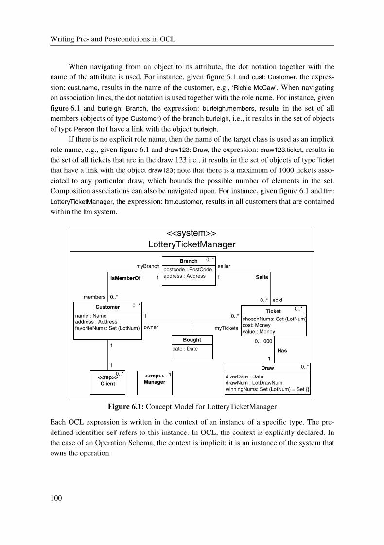
Writing Pre- and Postconditions in OCL
When navigating from an object to its attribute, the dot notation together with thename of the attribute is used. For instance, given figure 6.1 and cust: Customer, the expres-sion: cust.name, results in the name of the customer, e.g., ‘Richie McCaw’. When navigatingon association links, the dot notation is used together with the role name. For instance, givenfigure 6.1 and burleigh: Branch, the expression: burleigh.members, results in the set of allmembers (objects of type Customer) of the branch burleigh, i.e., it results in the set of objectsof type Person that have a link with the object burleigh.
If there is no explicit role name, then the name of the target class is used as an implicitrole name, e.g., given figure 6.1 and draw123: Draw, the expression: draw123.ticket, results inthe set of all tickets that are in the draw 123 i.e., it results in the set of objects of type Ticket
that have a link with the object draw123; note that there is a maximum of 1000 tickets asso-ciated to any particular draw, which bounds the possible number of elements in the set.Composition associations can also be navigated upon. For instance, given figure 6.1 and ltm:
LotteryTicketManager, the expression: ltm.customer, results in all customers that are containedwithin the ltm system.
Figure 6.1: Concept Model for LotteryTicketManager
Each OCL expression is written in the context of an instance of a specific type. The pre-defined identifier self refers to this instance. In OCL, the context is explicitly declared. Inthe case of an Operation Schema, the context is implicit: it is an instance of the system thatowns the operation.
name : Nameaddress : AddressfavoriteNums: Set (LotNum)
Customer
chosenNums: Set (LotNum)cost: Moneyvalue : Money
Ticket
<<rep>>Client
postcode : PostCodeaddress : Address
Branch
1
1
members 0..*
myBranch
1
seller
1
sold0..*
date : Date
Bought
1
owner
0..*
LotteryTicketManager<<system>>
0..*
0..*
0..*
0..*
<<rep>>Manager
1Draw 0..*
drawDate : DatedrawNum : LotDrawNumwinningNums: Set (LotNum) = Set {}
0..1000
1
myTickets
Has
IsMemberOf Sells
100
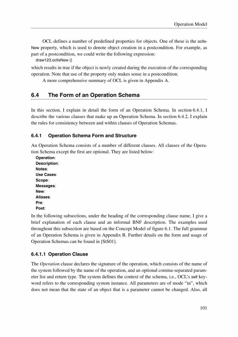
Operation Model
OCL defines a number of predefined properties for objects. One of these is the oclIs-
New property, which is used to denote object creation in a postcondition. For example, aspart of a postcondition, we could write the following expression:
draw123.oclIsNew ()
which results in true if the object is newly created during the execution of the correspondingoperation. Note that use of the property only makes sense in a postcondition.
A more comprehensive summary of OCL is given in Appendix A.
6.4 The Form of an Operation Schema
In this section, I explain in detail the form of an Operation Schema. In section 6.4.1, Idescribe the various clauses that make up an Operation Schema. In section 6.4.2, I explainthe rules for consistency between and within clauses of Operation Schemas.
6.4.1 Operation Schema Form and Structure
An Operation Schema consists of a number of different clauses. All clauses of the Opera-tion Schema except the first are optional. They are listed below:
Operation:Description:Notes:Use Cases:Scope:Messages:New:Aliases:Pre:Post:
In the following subsections, under the heading of the corresponding clause name, I give abrief explanation of each clause and an informal BNF description. The examples usedthroughout this subsection are based on the Concept Model of figure 6.1. The full grammarof an Operation Schema is given in Appendix B. Further details on the form and usage ofOperation Schemas can be found in [StS01].
6.4.1.1 Operation Clause
The Operation clause declares the signature of the operation, which consists of the name ofthe system followed by the name of the operation, and an optional comma-separated param-eter list and return type. The system defines the context of the schema, i.e., OCL’s self key-word refers to the corresponding system instance. All parameters are of mode “in”, whichdoes not mean that the state of an object that is a parameter cannot be changed. Also, all
101

Operation Schema Form and Structure
parameters have defined values, i.e., object references point to objects in the system—nonull references. The Operation clause has the following form:
“Operation” “:” SystemTypeName “::” OperationName “(” [ParameterList] ”)” [“:” ReturnType] “;”
The following example of an Operation clause declares the informWinners operation of Lot-
teryTicketManager, which has two parameters.Operation: LotteryTicketManager::informWinners (draw: Draw, winNums: Set (LotNum));
6.4.1.2 Description Clause
The Description clause provides a concise natural language description of the purpose andeffects of the operation. The Description clause has the following form:
“Description” “:” Text “;”
The following example of a Description clause describes the informWinners operation.
Description: This operation informs all winning lottery ticket holders that they won, where a ticketis classed as a winning one if it matches the winning numbers and is part of the given draw;
6.4.1.3 Notes Clause
The Notes clause provides additional comments about the respective operation. The com-ments are written in natural language and are deemed noteworthy. The Notes clause has thefollowing form:
“Notes” “:” Text “;”
The following example of a Notes clause is given for the informWinners operation.Notes: An informWinners operation can only be invoked by the Head Officer of the lottery;
6.4.1.4 Use Cases Clause
The Use Cases clause declares all use cases (0 or more) that have a (traceability) relation-ship with this operation. The Use Cases clause consists of a list of use cases (and use casestep numbers in curly brackets), each one terminated by a semicolon:
“Use Cases” “:” (UseCaseName [“::” “{” (StepNum “;” )+ “}” ] “;”)+
The following example of a Use Cases clause is given for the informWinners operation.Use Cases: DrawWinningLotteryTicket::{2; 3a;};
This clause would mean that the operation was derived from, or related to, steps 2 and 3a inthe Draw Winning Lottery Ticket use case.
6.4.1.5 Scope Clause
The Scope clause declares all those classes and associations from the Concept Model thatdefine the name space of the operation. Note that messages are not included in this clause(they are shown in the Messages clause). The Scope clause is a list of classes and associa-tions, each one terminated by a semicolon:
102

Operation Model
“Scope” “:” (ClassOrAssociationName “;”)+
An omitted Scope clause defaults to the entire namespace of the system. Also, for reasonsof convenience, rep classes are not included in the Scope clause.
To illustrate the Scope clause, the following example is given for the informWinners
operation.Scope: Customer; Ticket; Draw; Bought; Sells; Has;
The first three items are classes, the fourth one is an association class, and the last two areassociations.
6.4.1.6 Messages Clause
The Messages clause declares the possible messages that can be output with the executionof the operation. It has the following form:
“Messages” “:” (ActorWithMessages “;”)+
This clause declares the type of messages that can be sent by the operation together withtheir destinations, i.e. the receiving actor classes. ActorWithMessages shows the type of mes-sage that can be sent to a given actor class.
ActorWithMessages ::=ActorClassName “::” “{” (MessageTypeName [ “Throws” ExceptionMessages ] “;”)+ “}”
ExceptionMessages ::= MessageNameListMessageNameList ::= MessageName (“,” MessageName)*
ExceptionMessages defines the exceptions that might be thrown by a call denoted by themessage preceding the Throws keyword. The Throws keyword and its usage is described insection 6.8.2.The following example of a Messages subclause is given for the informWinners operation.
Messages: Client::{WonLottery;};Manager::{NumOfWinnersNotification; WinnerStatistics;};
The first line states that actors of type Client may be sent messages of type WonLottery. Thesecond line states that actors of type Manager may be sent messages of types NumOfWinners-
Notification and WinnerStatistics. Note that it does not indicate the number of messages thatmay be sent to the actors, and equally it does not indicate the number of actor instances thatmay receive a message.
6.4.1.7 New Clause
The New clause provides a declaration of all those names in an Operation Schema that referto new objects or (new) messages. All names declared in this clause are local to the schema.The New clause has the following form:
“New” “:” (ObjectOrCollectionDecl | MessageInstanceOrCollectionDecl)+
A name given in an ObjectOrCollectionDecl designates the name of an object or collection ofobjects that is used in the Post clause to indicate that an object or collection of objects have
103

Operation Schema Form and Structure
newly become part of the system state. Association objects can also be declared (i.e.,instances of association classes). Each name ideally declares a distinct object or collectionof objects, and it must be a unique name in the Operation Schema (i.e., no clashes withother identifiers). ObjectOrCollectionDecl has the following form:
ObjectOrCollectionDecl ::= ObjectDecl | ObjectCollectionDeclObjectDecl ::= ObjectName (“,” ObjectName)* “:” ClassName “;”ObjectCollectionDecl ::=
CollectionName (“,” CollectiontName)* “:” CollectionLiteral “(” ClassName “)” “;”
Any object declared in this clause is newly created with the execution of the operation.Therefore, these objects can not be used to match already existing objects in the typicaldeclarative matching style. For example, the following Operation Schema fragment is NOTwell-formed because minPayOut is not defined before the operation, i.e., minPayOut does notexist at precondition time and therefore should not be used in the Pre clause.
New: minPayOut: Ticket;Pre: winningTickets->includes (minPayOut)Post: winningTickets->forall (t | minPayOut.value <= t.value) ...
The New clause can also declare message instances and collections of message instances.The types of the message instances must be also mentioned in the Messages clause, other-wise this clause is not well-formed. New message instance declarations have the followingform:
MessageInstanceOrCollectionDecl ::= MessageInstanceDecl | MessageInstanceCollectionDeclMessageInstanceDecl ::= MessageNameList “:” MessageTypeName “;”MessageInstanceCollectionDecl ::=
MessageNameList “:” CollectionLiteral “(” MessageTypeName “)” “;”
Illustrating a New clause with object and message declarations, consider the followingexample of a New clause for the informWinners operation (which respects the Messagesclause example, shown earlier):
New: youWon: WonLottery;numWinners: NumOfWinnersNotification; stats: Set (WinnerStatistics);newTicket: Ticket; -- new object (the others are messages)
The first line declares a message instance of type WonLottery called youWon. The second linedeclares a message instance of type NumOfWinnersNotification called numWinners anddeclares a set of message instances of type WinnerStatistics called stats. The third linedeclares a new ticket object of type Ticket.
6.4.1.8 Aliases Clause
The Aliases clause provides a declaration of all those names in an Operation Schema thatrefer to expression-substitutions. Everything declared in this clause is local to the schema.The Aliases clause has the following form:
“Aliases” “:” ExpressionSubstitutionDecl+
104

Operation Model
An alias designates a name for an expression, which is written in OCL and is well-formed,i.e., the expression resolves to a valid type. This name must be unique in the OperationSchema (i.e., no clashes with other identifiers). ExpressionSubstitutionDecl has the followingform:
ExpressionSubstitutionDecl ::= Name “:” TypeName “Is” Expression “;”
Expression must conform to the type of TypeName. To illustrate an expression-substitution,one could declare some expression-substitutions for the informWinners operation, such as thefollowing ones:
winningTickets: Set (Ticket) Is draw.ticket->select (t | t.chosenNums = winNums));winners: Set (Customer) Is self.customer -> select (p |
p.myTickets->intersection (winningTickets)->notEmpty ());thereIsAtLeastAWinner: Boolean Is winners->notEmpty ();
winningTickets captures the set of all tickets associated to the draw that match the winningnumbers (where draw and winNums are parameters of the operation). winners captures the setof all customers that own one or more winning tickets. thereIsAtLeastAWinner evaluates totrue if there is at least a winner, otherwise it is false.
The name of the expression-substitution, e.g., winningTickets, can be used throughoutthe Operation Schema in all situations where the expression itself could be used correctly.An expression-substitution is similar to a macro, where the expression is substituted for thename in all places of use. However, there are two additional constraints on the substitution.First, the substitution is treated as an atom with respect to the context of substitution, over-riding precedence rules, i.e., one can think of the substituted expression as having parenthe-ses placed around it.
Expression-substitutions can also use decorators (i.e., @pre) within Expression. In fact,the expression that is substituted is interpreted in that context, and therefore care should betaken to use the correct decorator so that the interpretation is the intended one.
The Aliases clause allows schema-wide declaration of expressions to be made in adistinct and single place, which is in line with the proposal of Cook et al. [CKM+99a].
6.4.1.9 Pre Clause
The Pre clause defines a condition that represents the assumption on the state of the systemand/or parameters before the execution of the operation. It is a predicate written in OCL. Anomitted Pre clause means the condition defaults to true.
“Pre” “:” Condition “;”Condition ::= BooleanOCLExpression
To illustrate the Pre clause, the following example is given for the informWinners operation.Pre: thereIsAtLeastAWinner and winNums->size () = 5; -- LHS of ‘and’ is an expression-substitution
The Pre clause asserts that the operation is performed under the assumption that there is atleast a winner (note that thereIsAtLeastAWinner is an expression-substitution declared in the
105

Operation Schema Form and Structure
Aliases clause example from above) and that there are exactly 5 winning numbers (winNums
is a parameter of the operation).Note that the Pre clause may make use of Parameterized Predicates and Functions
(described in section 6.6).
6.4.1.10 Post Clause
The Post clause defines a condition that represents the required state of the system after theexecution of the operation. It is a predicate written in OCL. An omitted Post clause meansthe condition defaults to true.
“Post” “:” Condition “;”
A Post clause defines changes to system resources by way of assertions on the value thatthey have after the execution of the operation. In a Post clause, the variables that are used inthe description of the postcondition have two snapshots: one taken before the operation, andone taken after the operation. The snapshot taken before the operation is denoted by postfix-ing the decorator @pre to the expression that represents the entity, and the snapshot takenafter the operation is denoted simply by the expression that represents the entity, i.e., with-out decorator. Having these two values for an entity allows one to define the effect of theoperation on this entity relative to its value before the operation’s execution (@pre).
As a rule, any navigation to a frozen attribute or frozen association end (i.e., the corre-sponding Concept Model shows the property {frozen} for the item) does not require the addi-tion of the @pre suffix. Furthermore, for reasons of conciseness, it is often more convenientto drop the @pre suffix for all entities that are not changed by the operation (but are not fro-zen). However, care needs to be taken in maintenance activities that expressions, which relyon an entity to stay unchanged, are not invalidated, due to a change made to the OperationSchema.
To illustrate a Post clause, the following example is given.Post:
draw.winningNums = winNums &draw.drawNum = draw.drawNum@pre + 25;
The first line of the Post clause asserts that after the execution of the operation the winning-
Nums attribute of draw is equivalent to winNums (both draw and winNums are both parametersof the operation). The second line asserts that the drawNum attribute of draw is equal to itsprevious value plus 25.
A Post clause may make use of Parameterized Predicates and Functions (described insection 6.6), but it is not possible to refer to another Operation Schema within the postcon-dition of a schema. When such situations are deemed necessary, Parameterized Predicatesshould be used to describe the commonality and then they can be “called on” in the respec-tive schemas.
106
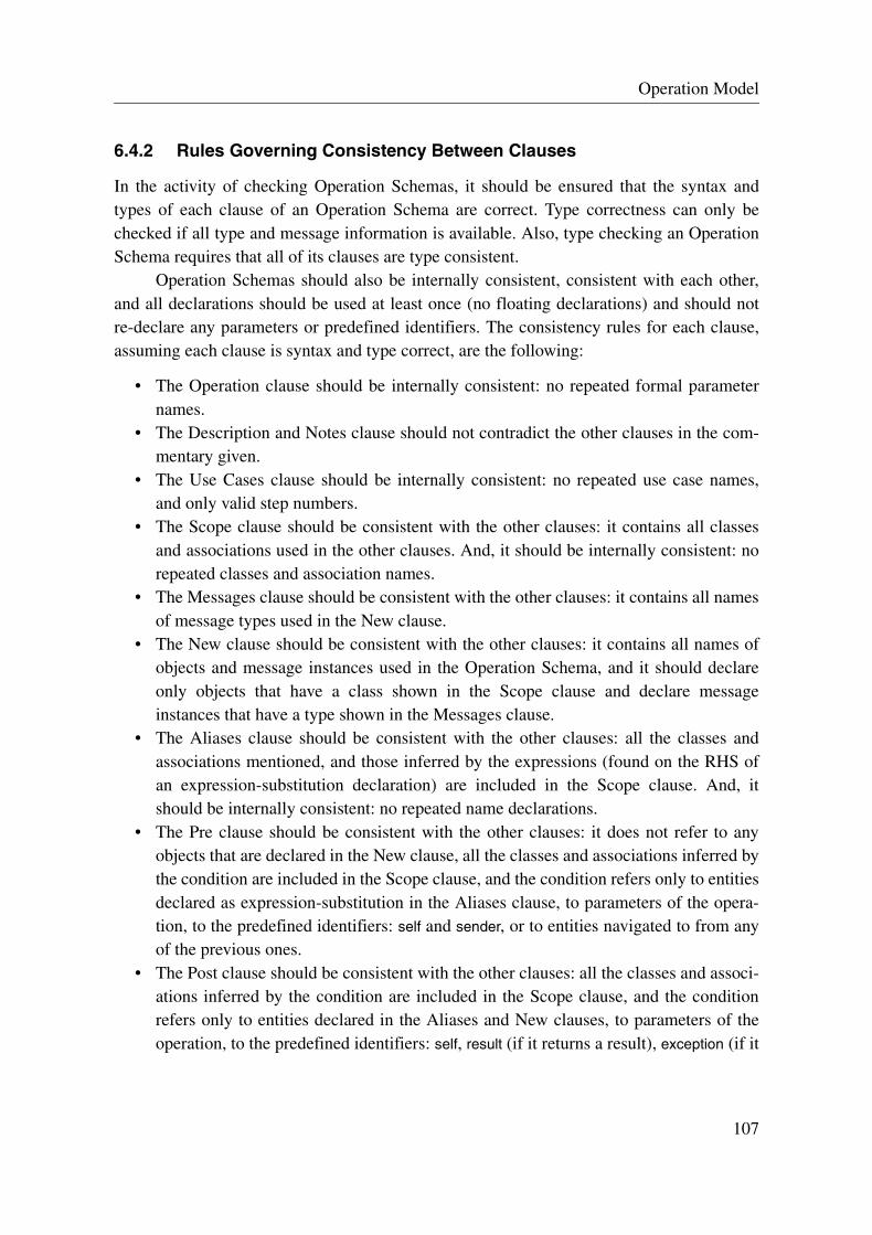
Operation Model
6.4.2 Rules Governing Consistency Between Clauses
In the activity of checking Operation Schemas, it should be ensured that the syntax andtypes of each clause of an Operation Schema are correct. Type correctness can only bechecked if all type and message information is available. Also, type checking an OperationSchema requires that all of its clauses are type consistent.
Operation Schemas should also be internally consistent, consistent with each other,and all declarations should be used at least once (no floating declarations) and should notre-declare any parameters or predefined identifiers. The consistency rules for each clause,assuming each clause is syntax and type correct, are the following:
• The Operation clause should be internally consistent: no repeated formal parameternames.
• The Description and Notes clause should not contradict the other clauses in the com-mentary given.
• The Use Cases clause should be internally consistent: no repeated use case names,and only valid step numbers.
• The Scope clause should be consistent with the other clauses: it contains all classesand associations used in the other clauses. And, it should be internally consistent: norepeated classes and association names.
• The Messages clause should be consistent with the other clauses: it contains all namesof message types used in the New clause.
• The New clause should be consistent with the other clauses: it contains all names ofobjects and message instances used in the Operation Schema, and it should declareonly objects that have a class shown in the Scope clause and declare messageinstances that have a type shown in the Messages clause.
• The Aliases clause should be consistent with the other clauses: all the classes andassociations mentioned, and those inferred by the expressions (found on the RHS ofan expression-substitution declaration) are included in the Scope clause. And, itshould be internally consistent: no repeated name declarations.
• The Pre clause should be consistent with the other clauses: it does not refer to anyobjects that are declared in the New clause, all the classes and associations inferred bythe condition are included in the Scope clause, and the condition refers only to entitiesdeclared as expression-substitution in the Aliases clause, to parameters of the opera-tion, to the predefined identifiers: self and sender, or to entities navigated to from anyof the previous ones.
• The Post clause should be consistent with the other clauses: all the classes and associ-ations inferred by the condition are included in the Scope clause, and the conditionrefers only to entities declared in the Aliases and New clauses, to parameters of theoperation, to the predefined identifiers: self, result (if it returns a result), exception (if it
107

Operation Schemas: Constructs, Rules, Assumptions, and Interpretations
can raise an exception) and sender, to message instances, or to entities navigated tofrom any of the previous ones.
Well-formedness rules for the expressions used in Operation Schemas are given in [StS01].
6.5 Operation Schemas: Constructs, Rules, Assumptions, and Interpretations
In this section, I introduce a number of constructs that are used to make specifying opera-tions with Operation Schemas less cumbersome and more intuitive. I also propose a numberof rules, assumptions, and interpretations that apply to Operation Schemas, and explaintheir meaning and utility in the context of specifying operations with them.
To be able to write and read Operation Schemas, it is necessary to understand themeaning of the various constructs used and the rules and assumptions that the modelimposes. Before I explain the various rules, assumptions, and interpretations that apply toOperation Schemas, I first introduce an additional language construct that is used whenexplaining these aspects of Operation Schemas.
Additional Language Construct: commercial-andNon-trivial pre- and postconditions will consist of multiple constraints on the system, whereeach constraint is described by a boolean expression that asserts a property that must holdtrue at the respective moment (i.e., before or after the operation). The condition is thereforedefined by the conjunction of each of these constraint atoms. For reasons of readability, it isadvantageous to highlight these constraint atoms and minimize the visibility of the conjunc-tion operator that glues these atoms together to form the condition. Standard practice inOCL is to use the keywords “pre” and “post” to separate each constraint atom [Omg01].However, this approach can become quite heavy and disruptive for the reader of large spec-ifications.
An alternative is to use a special character to separate the constraint atoms, where theuse of a single character offers minimal visual clutter. In this direction, commercial-and “&”is a good candidate, having an intuitive relationship to conjunction. Consequently, commer-cial-and is used as a constraint atom separator in Operation Schemas.
The commercial-and and the logical-and operators are logically equivalent, exceptcommercial-and has the lowest precedence of all operators. Note that in OCL logical-andhas a higher precedence than logical-implies, and therefore parentheses are not needed inthe use of logical-implies with commercial-and as atom separator.
Contrasting the two styles, the following two postconditions are logically equivalent:the one on the left-hand side is written using the multiple pre/post keyword style of OCL,and the one on the right-hand side is written using the proposed commercial-and style.
108

Operation Model
6.5.1 Asserting Creation and Deletion in Operation Schemas
The context in an Operation Schema is the system. The system consists of a (state) popula-tion of objects (i.e., instances of classes) and association links at any point in time. Withrespect to the system, an object exists only if it is part of the system’s state population. InOperation Schemas, instead of explicitly asserting that an object is created or destroyedwith the execution of an operation, one rather defines creation and destruction in terms ofwhat is part of state population of the system and what ceases to be part of it. One can judgean object as part of the system state if it has a composition link either directly or transitivelywith the system, e.g., an object that is a component of a component of the system is also partof the state population by transitivity. Thus, “creation” of an object is asserted by statingthat a composition association link between the object and the system (direct or transitive)was formed, and “destruction” of an object is asserted by stating that the composition asso-ciation link between the object and the system was removed. Taking into account the addi-tion and removal of objects from the state population of the system, Rule 1 is as follows:
Rule 1: An object is part of the state population of the system if and only if it has a direct or transitive composition association link with the system.
For example, given the Concept Model in figure 6.1, one can express the postcondition ofan operation that adds a new customer to the lottery ticket manager in the following way:
Operation: LotteryTicketManager::addNewCustomer (...);Aliases: newCust: Customer;Post: self.customer = self.customer@pre->including (newCust) ...
Note that it is also possible to use the oclIsNew property with the same meaning, i.e., new-
Cust.oclIsNew ().Equally, one can express the postcondition of an operation that removes a customer
from the lottery ticket manager in the following way (note that OCL does not have a prop-erty like oclIsRemoved):
Operation: LotteryTicketManager::removeCustomer (c: Customer);Post: self.customer = self.customer@pre->excluding (c);
Note that it is not necessary to assert that an association link is “created”. Creation of asso-ciation links is implicit in Operation Schemas, i.e., it is only necessary to assert that naviga-
post: effectApost: if condA and condB then
effectB andeffectC
elseeffectD
endifpost: effectE
Post: effectA &if condA and condB then
effectB &effectC
elseeffectD
endif &effectE
109

Consistency of Associations
tion between two objects is possible for the creation of the link to be implied. Similarly tolink “creation”, link “destruction” is also implicit, i.e., it is only necessary to assert that nav-igation between two objects is no longer possible for the destruction of the link to beimplied. However, an association object is a special case (i.e., objects of association classes,e.g., Bought in figure 6.1). According to UML [pp. B-4, Omg01] an association class is:
“A model element that has both association and class properties. An association class can be seen as an association that also has class properties, or as a class that also has association properties.”
I propose that one explicitly asserts that an association object becomes part of the system’sstate population with the operation’s execution by asserting the oclIsNew property of theobject, for example. This means an association object’s existence in the system is defined byits composition association link with the system. Also, the composition link can be used innavigation expressions to collect all association objects of an association class, for example.However, with this approach, care must be taken that the association object is also madepart of the corresponding association, otherwise the Post clause would be incomplete, i.e.,the object does not make sense if it is not a member of the corresponding association.
In the case of removing an association object from the system, it is necessary to eitherremove the link that it represents from the association or remove the composition link it haswith the system. The two-way approach in “destruction” is taken purely for reasons of con-venience.
6.5.2 Consistency of Associations
Revisiting the Post clause for the removeCustomer operation (shown above), what happens ifthe object c is also involved in other associations at the time when the composition linkbetween c and the system is removed?
Answering this question directly: all association links of the system only make senseif they relate existing objects. It is a well known consistency constraint for object modelsthat when an object is removed from the state population of the system that all associationlinks connected to it have to be removed too. Although it would be possible to explicitlystate all association links that must be destroyed, this is quite cumbersome in the presenceof numerous associations. In light of this fact, it is implicit in the use of Operation Schemasthat association links of no longer existing objects (wrt. the system) are removed. A conse-quence of this approach is that all associations with instances that are implicitly changedaccording to this rule also need to be mentioned in the Scope clause of the respective Oper-ation Schema.
With respect to the consistency of associations constraint placed on Operation Sche-mas, Rule 2 is as follows:
Rule 2: Removal of an object from the system implies implicitly that all association links in the system that included the destroyed object are also destroyed.
110

Operation Model
For example, given the Concept Model in figure 6.1, the removal of a ticket from the lotteryticket manager requires only that the composition link is asserted to be removed:
Operation: LotteryTicketManager::removeTicket (t: Ticket);Post: self.ticket = self.ticket@pre->excluding (t);
Thus, it would be unnecessary to write the following, because it is implied by Rule 2:Post: self.ticket = self.ticket@pre->excluding (t) &
t.seller->isEmpty () & -- unnecessary due to Rule 2
t.owner->isEmpty () & -- unnecessary due to Rule 2
t.draw->isEmpty (); -- unnecessary due to Rule 2
6.5.3 Frame Assumption
Looking at the postcondition as a whole, it describes the effect of the system operation onthe system state. Each assertion describes a constraint on the change to an object, an associ-ation link or a collection of these ones. However, a question that can be posed is: What hap-pens to those objects/links that are not mentioned by the postcondition? Do they stayunchanged? Addressing this problem, I now look at the frame assumption for OperationSchemas.
According to [Mor94], the frame of an operation specification is the list of all vari-ables that can be changed by the operation. In an Operation Schema, this list is a subset ofall those objects and association links that have their type included in the Scope clause. Thepostcondition of a specification describes all the changes to the frame variables, and sincethe specification is declarative, it is assumed that the postcondition must also state all theframe variables that stay unchanged. The reason is simple: if the unchanged frame variableswere left unmentioned, they would be free to be given any value, and the result would stillconform to the specification.
In writing pre- and postconditions for Operation Schemas, it is at least convenient tochange the above “open world” assumption to a “closed world” one, because the goal is towrite complete functional descriptions of operations (with respect to the state space of thesystem). Note that it is also possible, and in some cases even desirable, to write partialdescriptions; however, this aspect is not addressed in this work. Interested readers arereferred to [Ja95] for a discussion.
Currently, many formal approaches, such as, Z [Spi89], VDM [Jon86], Larch[GHW85], etc. explicitly state what happens to each frame variable—even for those vari-ables that stay unchanged. This approach soon becomes cumbersome to write and error-prone, particularly for specifications that have complex case distinctions (where the com-plete frame is the combination of all the variables read/changed in each different case). Oneapproach that avoids this extra work is to imply a “... and nothing else changes” rule whendealing with these types of declarative specifications [BMR93, Lan95, BMR95]. Thismeans that the specification implies that the frame variables are changed according to thepostcondition, but that all other (unmentioned) frame variables are left unchanged. This
111

Frame Assumption
approach reduces the size of the specification, thus increases its readability, and makes theactivity of writing specifications less error prone. This convention is therefore adhered towith Operation Schemas.
However, there is a slight problem with this assumption in the case of implicitremoval—a consequence of the association consistency assumption (Rule 2). For example,let us reconsider the Operation Schema for the removeTicket system operation (of the lotteryticket manager).
Operation: LotteryTicketManager::removeTicket (t: Ticket);Post: self.ticket = self.ticket@pre->excluding (t);
If one strictly applies the frame assumption “... and nothing else changes”, the associationsBought, Sells, and Has would stay unchanged because they are left unmentioned. Taken liter-ally, this would lead to an inconsistent system state. Thus, it is necessary to take intoaccount Rule 2, stated in section 6.5.2, for the frame assumption of Operation Schemas.
In addition, there is another case to consider: What happens to attributes of newobjects that are not mentioned in the postcondition? One could imagine four different (butnon-exclusive) approaches for this situation1: 1) attributes of new objects that are not men-tioned in the postcondition can take any consistent value; 2) the unmentioned attributes haveunknown values, where any expressions that attempt to navigate to their values are unde-fined; 3) the unmentioned attributes get predefined default values; or 4) the specification isincorrect if a value is not given to the respective attributes. The first approach is not suffi-ciently restrictive, because the value given to the attribute may be unknowingly used as if itcontains a credible value. The second one takes a direct approach to unmentioned attributes.And, the third and fourth approaches require the specifier to constrain the value of theattribute to one that indicates “I am uninitialized”. Using these approaches, the datatypeswould need to be chosen carefully. For example, given a numOfFish attribute of type Natural,which is part of an object of class Lake, it is difficult to know what value one can give to thisattribute to indicate that it is “uninitialized”, because the top-end limit is uncertain, i.e., alarge, nutrient-rich lake could have an enormous number of fish, and the bottom-end limitcould be zero, i.e., clearly a lake that is overly acidic would have zero fish. In such cases, itwould be necessary to extend the datatype, e.g., NumFish, by including some value whichcould stand for uninitialized, e.g., -1. However, such workarounds are not in the spirit ofconceptual descriptions.
The approach chosen is the second one, which also allows predefined default values(third approach), and it is stated as Rule 3:
Rule 3: All unmentioned attributes of a newly created object that have predefined default values are given those default values, but if there exists an unmentioned attribute that does not have a default value then its value is unknown, where any expression that attempts to navigate to its value is undefined.
1. Recall that all attributes of objects are datatypes.
112

Operation Model
Taking into account Rule 2 and Rule 3, the revised frame assumption is given by Rule 4,below.
Rule 4: No frame variables of the system are changed with the execution of the operation other than those that are explicitly mentioned to be changed by the post-condition, the associations that are implicitly modified as defined by Rule 2, and the unmentioned attributes of new objects in the system that are treated according to Rule 3.
For example, let us consider the Operation Schema for the makeDrawAndRemoveOldest sys-tem operation (of the lottery ticket manager), which creates a new draw and removes theoldest one along with all the tickets that were part of that draw.
Operation: LotteryTicketManager::makeDrawAndRemoveOldest (num: LotDrawNum,drawnOn: Date);
Aliases: newDraw: Draw;oldDraw: Draw Is self.draw->any (old | self.draw->forall (d | old.date <= d.date));
Post: newDraw.oclIsNew () & -- newDraw has become a new member of the system
newDraw.drawDate = drawnOn &newDraw.drawNum = num &self.draw = self.draw@pre->excluding (oldDraw)->including (newDraw) &
-- old one removed from and new one added to system
self.ticket = self.ticket@pre - oldDraw.ticket; -- all tickets of that draw are removed from system
With respect to this postcondition, the frame assumption states that the only changes madeto the state population of the system were: newDraw was added to the system and itsattributes drawDate, drawNum and winningNums were (implicitly) given values, oldDraw wasremoved from the system, all ticket objects associated to oldDraw were removed from thesystem, and all association links that the removed objects were involved in no longer exist(Rule 2). It is important to note that winningNums is constrained to be given its default value,which is the empty set (shown in the Concept Model).
Looking closer at the Post clause, the fourth line of the Post clause states that the setof draw objects in the system (immediately) after the operation is equivalent to the set ofdraw objects in the system before the operation minus oldDraw but plus newDraw. However,looking at the first line of the Post clause, one can see that newDraw has already beenasserted as a new member of the system state population. In an attempt to remove the redun-dancy, it would not be a good idea to remove the postfixed expression ->including (newDraw)
from line four of the Post clause, because this would create a contradiction with line one ofthe Post clause. Note that removing line one of the Post clause would eliminate the redun-dancy.
6.5.4 Incremental Descriptions
In describing the effects of an operation, it can be useful to construct a postcondition in anincremental fashion, i.e., a particular effect of an operation may be defined by a combina-
113
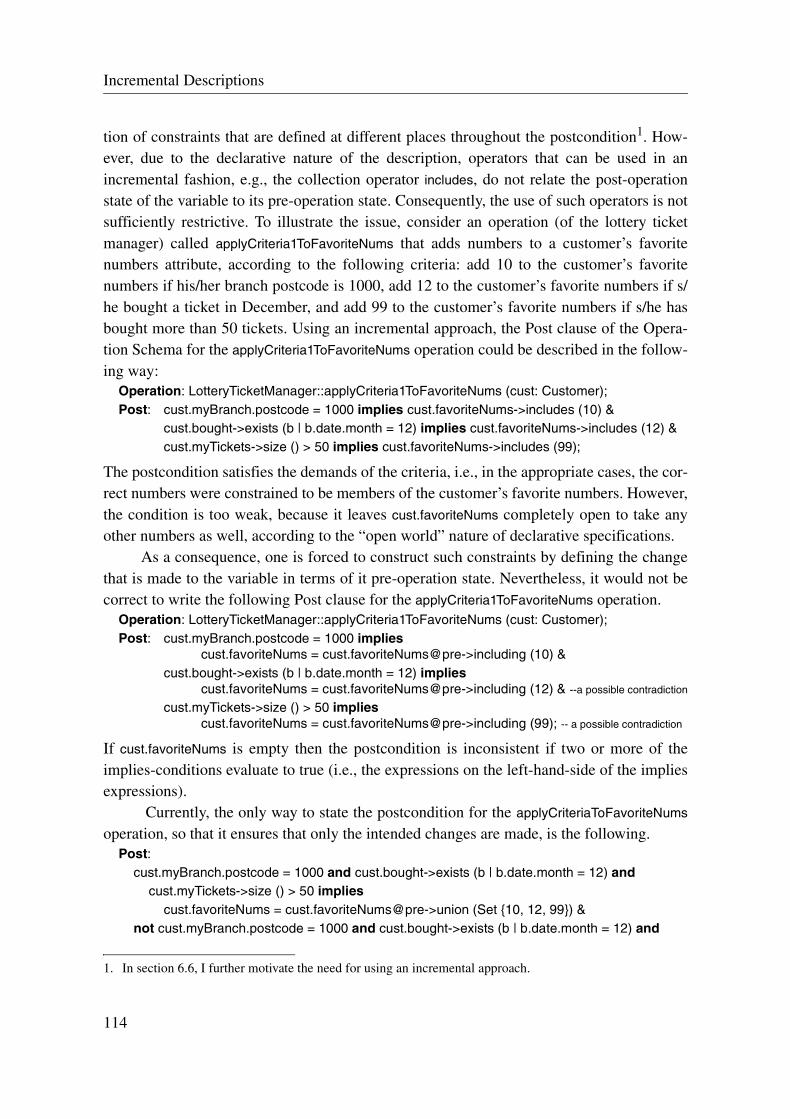
Incremental Descriptions
tion of constraints that are defined at different places throughout the postcondition1. How-ever, due to the declarative nature of the description, operators that can be used in anincremental fashion, e.g., the collection operator includes, do not relate the post-operationstate of the variable to its pre-operation state. Consequently, the use of such operators is notsufficiently restrictive. To illustrate the issue, consider an operation (of the lottery ticketmanager) called applyCriteria1ToFavoriteNums that adds numbers to a customer’s favoritenumbers attribute, according to the following criteria: add 10 to the customer’s favoritenumbers if his/her branch postcode is 1000, add 12 to the customer’s favorite numbers if s/he bought a ticket in December, and add 99 to the customer’s favorite numbers if s/he hasbought more than 50 tickets. Using an incremental approach, the Post clause of the Opera-tion Schema for the applyCriteria1ToFavoriteNums operation could be described in the follow-ing way:
Operation: LotteryTicketManager::applyCriteria1ToFavoriteNums (cust: Customer);Post: cust.myBranch.postcode = 1000 implies cust.favoriteNums->includes (10) &
cust.bought->exists (b | b.date.month = 12) implies cust.favoriteNums->includes (12) &cust.myTickets->size () > 50 implies cust.favoriteNums->includes (99);
The postcondition satisfies the demands of the criteria, i.e., in the appropriate cases, the cor-rect numbers were constrained to be members of the customer’s favorite numbers. However,the condition is too weak, because it leaves cust.favoriteNums completely open to take anyother numbers as well, according to the “open world” nature of declarative specifications.
As a consequence, one is forced to construct such constraints by defining the changethat is made to the variable in terms of it pre-operation state. Nevertheless, it would not becorrect to write the following Post clause for the applyCriteria1ToFavoriteNums operation.
Operation: LotteryTicketManager::applyCriteria1ToFavoriteNums (cust: Customer);Post: cust.myBranch.postcode = 1000 implies
cust.favoriteNums = cust.favoriteNums@pre->including (10) &cust.bought->exists (b | b.date.month = 12) implies
cust.favoriteNums = cust.favoriteNums@pre->including (12) & --a possible contradiction
cust.myTickets->size () > 50 impliescust.favoriteNums = cust.favoriteNums@pre->including (99); -- a possible contradiction
If cust.favoriteNums is empty then the postcondition is inconsistent if two or more of theimplies-conditions evaluate to true (i.e., the expressions on the left-hand-side of the impliesexpressions).
Currently, the only way to state the postcondition for the applyCriteriaToFavoriteNums
operation, so that it ensures that only the intended changes are made, is the following.Post:
cust.myBranch.postcode = 1000 and cust.bought->exists (b | b.date.month = 12) andcust.myTickets->size () > 50 implies
cust.favoriteNums = cust.favoriteNums@pre->union (Set {10, 12, 99}) ¬ cust.myBranch.postcode = 1000 and cust.bought->exists (b | b.date.month = 12) and
1. In section 6.6, I further motivate the need for using an incremental approach.
114

Operation Model
cust.myTickets->size () > 50 impliescust.favoriteNums = cust.favoriteNums@pre->union (Set {12, 99}) &
cust.myBranch.postcode = 1000 and not cust.bought->exists (b | b.date.month = 12) andcust.myTickets->size () > 50 implies
cust.favoriteNums = cust.favoriteNums@pre->union (Set {10, 99}) &cust.myBranch.postcode = 1000 and cust.bought->exists (b | b.date.month = 12) and
not cust.myTickets->size () > 50 impliescust.favoriteNums = cust.favoriteNums@pre->union (Set {10, 12}) &
not cust.myBranch.postcode = 1000 and not cust.bought->exists (b | b.date.month = 12) andcust.myTickets->size () > 50 implies
cust.favoriteNums = cust.favoriteNums@pre->including (99) ¬ cust.myBranch.postcode = 1000 and cust.bought->exists (b | b.date.month = 12) and
not cust.myTickets->size () > 50 impliescust.favoriteNums = cust.favoriteNums@pre->including (12) &
cust.myBranch.postcode = 1000 and not cust.bought->exists (b | b.date.month = 12) andnot cust.myTickets->size () > 50 implies
cust.favoriteNums = cust.favoriteNums@pre->including (10) &--note that one does not need to state the case when no change to the set is required (according to the frame assumption)
Clearly, if I defined an expression-substitution (Aliases clause) for each of the three condi-tions, the postcondition would be smaller. The same number of cases would nevertheless beneeded.
For the purposes of facilitating incremental description of sets in an OperationSchema, the minimum set principle is introduced.
6.5.4.1 Minimum Set Principle
The minimum set principle allows one to express incrementally the elements that are addedand/or removed from a set with the execution of an operation. Unless asserted otherwise, allsets that can be constructed by navigation are subject to the minimum set principle in thepostcondition (Post clause) of an Operation Schema. The minimum set principle is definedin the following way.
Definition 6.4: The minimum set principle states that each set referred to in a postcondi-tion is the smallest possible set that fulfills the postcondition and contains all the elementsof the original set (i.e., the contents of the set before the operation) minus the elementswhose removal is asserted in the postcondition.
The minimum set principle is complementary to the frame assumption (Rule 4): togetherthey state, more or less, that nothing changes other than what is explicit in the postcondi-tion.
Applying the minimal set principle to the Post clause of theapplyCriteriaToFavoriteNums operation shown earlier, one is able to write the following post-condition and get the desired effect:
115

Incremental Descriptions
Post:cust.myBranch.postcode = 1000 implies cust.favoriteNums->includes (10) &cust.bought->exists (b | b.date.month = 12) implies cust.favoriteNums->includes (12) &cust.myTickets->size () > 50 implies cust.favoriteNums->includes (99)
With respect to the above Post clause, intuitively the minimum set principle states thatcust.favoriteNums is equivalent to the cust.favoriteNums@pre with the addition of 0, 1, 2, or 3different numbers (i.e., 10, 12, and/or 99) depending on which of the three implies-condi-tions hold in the postcondition.
Clearly, this version is markedly shorter and easier to read/write/understand (com-pared to the previous Post clause). Note that the relationship between the two approaches isexponential: there are 2n - 1 separate cases for n cases. Hence, the usefulness of an incre-mental description becomes even more noticeable as n gets larger.
The minimum set principle can also be applied to collections in general. If the mini-mum set principle is applied to a bag, duplicates are not accounted for. For example,
Pre: bagX->isEmpty ();Post: bagX->includes (x1) &
bagX->includes (x1);
is equivalent to:Post: bagX->includes (x1);
therefore the second “includes” expression is redundant. An additional constraint isrequired to assert that the bag contains two x1 elements, e.g., bagX->count(x1) = 2. In fact,this is a necessary condition for one to be able to reason about the size of the bag, otherwisethe resulting bag could be any size, i.e., it could contain any number of repeated x1 elementsand still conform to the postcondition.
Beyond the advantages of avoiding case distinction explosion, the incremental style,facilitated by the minimum set principle, has an advantage over the “all in a single condi-tion” style in that it allows for easier maintenance of case distinctions in postconditions. Forexample, there could exist an operation (of the lottery ticket manager) that allows a branchto swap a customer with another branch in the following way.
Operation: LotteryTicketManager::swapMembers (cust1: Customer, cust2: Customer,b1: Branch, b2: Branch);
Post: b1.members->excludes (cust1) & -- the link between b1 and cust1 is removed
b2.members->includes (cust1) & -- the link between b2 and cust1 is added
b2.members->excludes (cust2) & -- the link between b2 and cust2 is removed
b1.members->includes (cust2); -- the link between b1 and cust2 is added
To illustrate a change to the Post clause, one could imagine in maintenance activities that itis necessary to add another customer to branch b1 as part of the operation. The change to theOperation Schema would be the following:
Operation: LotteryTicketManager::swapMembers (cust1: Customer, cust2: Customer,cust3: Customer, b1: Branch, b2: Branch);
Post: b1.members->excludes (cust1) &
116

Operation Model
b2.members->includes (cust1) &b2.members->excludes (cust2) &b1.members->includes (cust2) &b1.members->includes (cust3); -- the link between b1 and cust3 is added
This example shows the constructive nature of postconditions that apply the minimum setprinciple.
Advocating the use of the minimum set principle, Rule 5 is as follows:
Rule 5: The minimum set principle is applied to the interpretation of sets in the postconditions of Operation Schemas.
It would be valuable to be able to use a similar constructive approach for the incrementaldescription of other data structures too. In this direction, incremental plus and minus fornumeric types are discussed in the next subsection.
6.5.4.2 Incremental Plus and Minus
Incremental plus and minus can be used to construct the value of numeric types in a Postclause of an Operation Schema. Incremental plus and minus can be realized in a Post clauseby the use of the following operators: “+=” and “-=”. These operators have the followingmeaning: the post-operation value of a numeric type is equivalent to its pre-operation valueplus the sum of all values on the right-hand sides of all += operators used in the postcondi-tion that refer to the value of the numeric type, minus the sum of all values on the right-handsides of all -= operators that refer to the value of the numeric type. This means that the fol-lowing postcondition, for example:
Post: obj.x += 5 &obj.x -= 4;
is equivalent to this one:Post: obj.x = obj.x@pre + 1;
Taking a larger example, there is an operation (of the lottery ticket manager) that applies anew ticket valuation scheme to a given ticket called applyNewValueSchemeToTicket. TheOperation Schema for this operation takes advantage of incremental plus and minus todescribe the postcondition (Post clause), shown below.
Operation: LotteryTicketManager::applyNewValueSchemeToTicket (t: Ticket);Post: t.seller.postcode > 2000 implies
t.value += 100 & -- an additional 100 if the seller has a postcode greater than 2000
t.seller.members->size > 100 impliest.value += 20 & -- an additional 20 if the seller of the ticket has over 100 members
t.owner.favoriteNums->intersection (Set {5, 10, 15})->notEmpty () impliest.value += 50 & --an additional 50 if the owner of the ticket has 5,10,15 as one of his/her favorite #s
t.bought.date.year = 2000 impliest.value += 10 & -- an additional 10 if the ticket was bought in the year 2000
117

Shorthands and Additional Language Constructs
t.draw.drawNum < 15 and t.value > 100 impliest.value -= 10; -- withdrawal of 10 if the ticket was for a draw that had a num less than 15
-- and the final value of the ticket is greater than 100
For this type of postcondition, the traditional approach would have required that one enu-merates each case (all 31 of them!).
Nevertheless, care needs to be taken when the incremental style is mixed with theother styles.
Post: ...obj.x += 5 & -- line oneobj.x -= 4 & -- line twoobj.x = obj.x@pre + 2 & -- line threeobj.x = 2 -- line four
The above example is an erroneous specification: line three is in contradiction with theresult defined by the incremental plus and minus, and line four would require that obj.x@pre
be either 0 or 1 depending on whether line three was brought into agreement with line oneand two or vice versa.
Apart from supporting incremental descriptions, an advantage of using incrementalplus and minus is that it facilitates more concise expressions by reducing the size of con-straints on numeric types. Unfortunately, the incremental plus and minus facility can not beextended to other types of numeric operations (e.g. multiplication), because it relies on thecommutativity of additions and subtractions.
6.5.5 Shorthands and Additional Language Constructs
In this subsection, some shorthands and additional language constructs are defined to makethe job of the specifier less laborious and therefore less error-prone.
Shorthand Expression: if-then-elsif*-else expressionsIf-then-else expressions prove to be a common and natural way to define case distinctions.With multi-case distinction, if-then-else expressions can be considerably more concise thanlogical-implies expressions, and arguably easier to write and read by those specifiers thatare more comfortable with imperative styles (due to the similarity of if-then-else expres-sions to if-then-else statements in imperative programming languages).
Often in writing pre- and postconditions, one comes across cases where the assertionof an effect is dependent on the truth of a series of conditions. In an imperative program-ming language, one usually has the facility of an “elsif”-like construct to define the hierar-chy of conditions in a uniform manner. In OCL, it is only possible to construct such ahierarchy by nesting if-then-else expressions, i.e., placing if-then-else expressions withinthe else-part of other if-then-else expressions. However, this practice can become cumber-some as the depth of nesting increases, and it most probably has a negative impact on clarityfor the reader and even the writer. Taking a leaf out of the imperative programming lan-
118
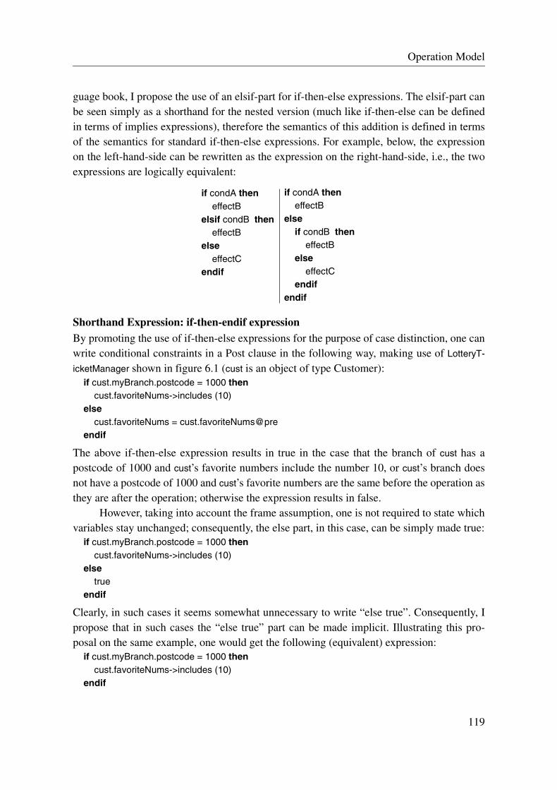
Operation Model
guage book, I propose the use of an elsif-part for if-then-else expressions. The elsif-part canbe seen simply as a shorthand for the nested version (much like if-then-else can be definedin terms of implies expressions), therefore the semantics of this addition is defined in termsof the semantics for standard if-then-else expressions. For example, below, the expressionon the left-hand-side can be rewritten as the expression on the right-hand-side, i.e., the twoexpressions are logically equivalent:
Shorthand Expression: if-then-endif expressionBy promoting the use of if-then-else expressions for the purpose of case distinction, one canwrite conditional constraints in a Post clause in the following way, making use of LotteryT-
icketManager shown in figure 6.1 (cust is an object of type Customer):if cust.myBranch.postcode = 1000 then
cust.favoriteNums->includes (10)else
cust.favoriteNums = cust.favoriteNums@preendif
The above if-then-else expression results in true in the case that the branch of cust has apostcode of 1000 and cust’s favorite numbers include the number 10, or cust’s branch doesnot have a postcode of 1000 and cust’s favorite numbers are the same before the operation asthey are after the operation; otherwise the expression results in false.
However, taking into account the frame assumption, one is not required to state whichvariables stay unchanged; consequently, the else part, in this case, can be simply made true:
if cust.myBranch.postcode = 1000 thencust.favoriteNums->includes (10)
elsetrue
endif
Clearly, in such cases it seems somewhat unnecessary to write “else true”. Consequently, Ipropose that in such cases the “else true” part can be made implicit. Illustrating this pro-posal on the same example, one would get the following (equivalent) expression:
if cust.myBranch.postcode = 1000 thencust.favoriteNums->includes (10)
endif
if condA theneffectB
elsif condB theneffectB
elseeffectC
endif
if condA theneffectB
elseif condB then
effectBelse
effectCendif
endif
119

Shorthands and Additional Language Constructs
Note that the resulting type of an “if-then-endif” is always boolean. In terms of semantics,this addition is proposed as a shortcut, and therefore the semantics are defined in terms of if-then-else expressions.
Additional Language Construct: aggregateWriting constraints on objects and messages (see section 5.7) can be quite cumbersome,verbose and even error-prone if one does not have a mechanism for defining their compositevalues. The composite value of an object is defined as the combination of all its valueattributes (recall that according to a Concept Model, all attributes of objects are data values).And the composite value of a message is defined as the combination of all its parameters:object references and/or data values.
For the purpose of denoting composite values of both objects and messages, an Ada-style aggregate notation for denoting composite values is introduced [Bar96]. An aggregateis written by associating a value with each attribute, denoted by its name. The followingaggregate defines the composite value of a Ticket object (conforming to the Concept Modelshown in figure 6.1):
(cost => 5, value => 5.0E6, chosenNums => Set {5, 7, 23, 27, 32})
An advantage of aggregates is that related values are kept together in one place. An aggre-gate is more than just a shorthand, defined in terms of standard expressions. It is an addi-tional construct of the language used by Operation Schemas, and therefore can be seen as anextension of OCL.
Additional Language Construct: all propertyDue to the “by-reference” semantics of objects and messages, one can not refer to theircomposite value directly. For this purpose, the property “all” is introduced to denote thecomposite value of an object or message (again taken from Ada [Bar96]). The all propertycan be useful in comparing values of objects/messages, and as will be shown in the nextsubsection, it can be used to assert that an object is created as a clone of another object.
The all property can be used to write expressions like the following, given that t is anobject of type Ticket:
t.all = (cost => 5, value => 5.0E6, chosenNums => Set {5, 7, 23, 27, 32})
This expression evaluates to true if the object referenced by t has the corresponding attributevalues. The above condition is equivalent to:
t.cost = 5 &t.value = 5.0E6 &t.chosenNums = Set {5, 7, 23, 27, 32}
Therefore in general, an aggregate can be used to denote the value of an object or message,and consequently the following (generic) expression:
x.all = (a1 => v1, a2 => v2, ...)
is equivalent to:
120

Operation Model
x.a1 = v1 & x.a2 = v2 & ...
The all property is more than just a shorthand that can be defined in terms of standardexpressions. It is an additional construct of the language used by Operation Schemas, andtherefore can be seen as an extension of OCL. One way to realize this extension would be toadd the “all” property to the standard OCL type OclAny.
Shorthand: parameterized oclIsNewTaking advantage of the aggregate notation, it would be useful to parameterize the oclIsNewproperty of objects in OCL by an aggregate that denotes all the (initial) attribute values ofthe object or all the actual parameters of a message. Thus, the oclIsNew property canoptionally take a composite value as parameter. For example, in a Post clause one couldassert the following:
newTicket.oclIsNew ((cost => 5, value => 5.0E6, chosenNums => Set {5, 7, 23, 27, 32}))
which means that newTicket has become part of the system with the execution of the opera-tion, and all its attributes were initialized according to the composite value. This expressionis logically equivalent to:
newTicket.oclIsNew () &t.cost = 5 &t.value = 5.0E6 &t.chosenNums = Set {5, 7, 23, 27, 32}
The proposed notation ensures that all attributes of a newly created object were constrainedto the given values, and none of them were forgotten.
In general, it is possible to define the parameterized oclIsNew property in terms ofstandard expressions and the “all” property. Therefore, the following (generic) expression:
newX.oclIsNew ((a1 => v1, a2 => v2, ...))
is equivalent to / and can be seen as a shorthand for: newX.oclIsNew () & newX.all = (a1 => v1, a2 => v2, ...)
Taking into account the expanded form of the shorthand for the parameterized oclIsNewproperty, there is nothing stopping one from using any kind of composite value as parame-ter. For instance, one could assert that a new object is a clone of another object, i.e., in a Postclause one could write the following expression:
newTicket.oclIsNew (otherTicket.all)
which means that newTicket has become part of the system with the execution of the opera-tion and all its attributes values match those of otherTicket.
Therefore, in general, the parameter of the oclIsNew property may be any compositevalue, where the following (generic) expression:
newX.oclIsNew (value)
in its expanded form is the following one. newX.oclIsNew () & newX.all = value
121

Reusing Parts and Reducing the Size of Operation Schemas by Functions and Parameterized
In terms of semantics, the parameterized oclIsNew property can be defined in terms of otherexpressions, and therefore it can be seen simply as a shorthand.
Shorthand: oclIsNew for collectionsIn addition to using aggregates with oclIsNew, it would seem useful to allow oclIsNew to bea property of collections. In this case, the oclIsNew property would optionally take a naturalnumber as parameter. For example, in a Post clause one could assert the following:
aBunchOfNewTickets.oclIsNew (32)
which means that there are 32 new tickets that have become part of the system with the exe-cution of the operation, and they are members of the collection aBunchOfNewTickets. Thisexpression is logically equivalent to:
aBunchOfNewTickets -> forall (t | t.oclIsNew () ) &aBunchOfNewTickets -> size () = 32
The proposed notation allows one to concisely assert the creation of a number of newobjects.
The signature of the property for collections is the following:oclIsNew (size: Integer): Boolean
It takes a single parameter, having the meaning that the specified number of objects arenewly created and they are members of the collection.
In terms of semantics, “oclIsNew for collections” can be defined in terms of otherexpressions, and therefore it can be seen simply as a shorthand.
6.6 Reusing Parts and Reducing the Size of Operation Schemas by Functions and Parameterized Predicates
In this section, I introduce two mechanisms that can be used in Operation Schemas for thepurposes of reusing predicates and functions, and also for regulating the size of OperationSchemas, so that they do not become overly large.
The incremental style of description, proposed in section 6.5.4, the frame assumption,defined in section 6.5.3, and the various shorthands, proposed in section 6.5.5, help to makeOperation Schemas more concise. These approaches by themselves however do not addressthe ease of writing and reading Operation Schemas that have a large number of constraints.Finney et al. have empirical evidence from controlled experiments that suggests that struc-turing a specification into schemas of about 20 lines significantly improves comprehensibil-ity over a monolithic specification [FFF99]. Using this result as a guideline, it is necessaryto offer the specifier mechanisms to structure large Operation Schemas into a form thatobeys this guideline.
To this end, one common approach is to use multiple pre- and postcondition pairs forstructuring operations. This approach was originally proposed by Wing, and she called it
122
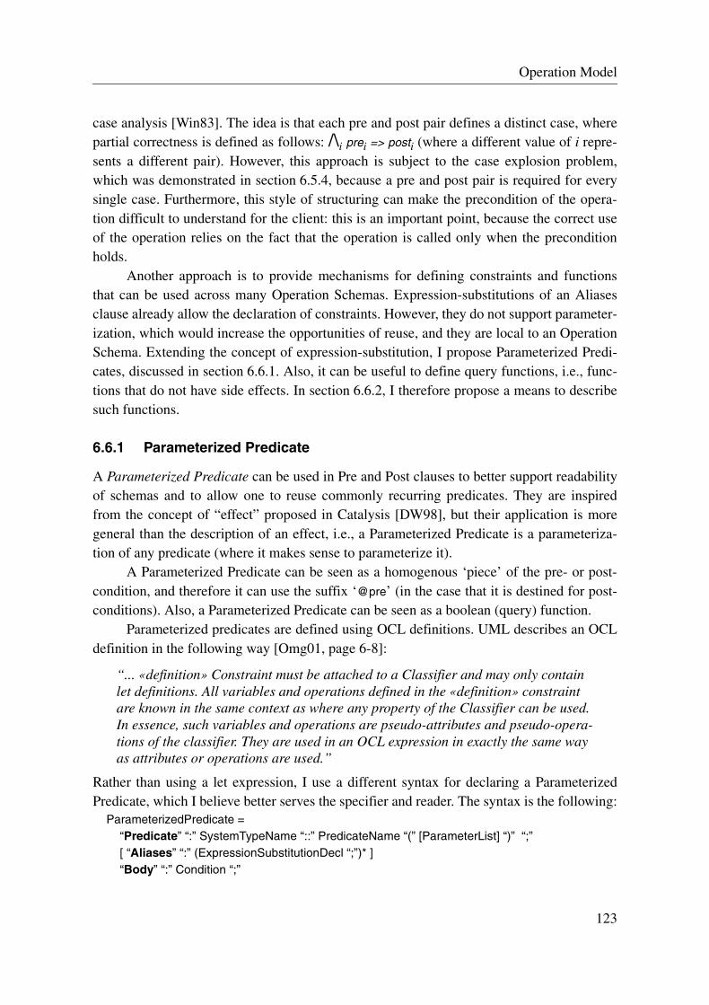
Operation Model
case analysis [Win83]. The idea is that each pre and post pair defines a distinct case, wherepartial correctness is defined as follows: /\i prei => posti (where a different value of i repre-sents a different pair). However, this approach is subject to the case explosion problem,which was demonstrated in section 6.5.4, because a pre and post pair is required for everysingle case. Furthermore, this style of structuring can make the precondition of the opera-tion difficult to understand for the client: this is an important point, because the correct useof the operation relies on the fact that the operation is called only when the preconditionholds.
Another approach is to provide mechanisms for defining constraints and functionsthat can be used across many Operation Schemas. Expression-substitutions of an Aliasesclause already allow the declaration of constraints. However, they do not support parameter-ization, which would increase the opportunities of reuse, and they are local to an OperationSchema. Extending the concept of expression-substitution, I propose Parameterized Predi-cates, discussed in section 6.6.1. Also, it can be useful to define query functions, i.e., func-tions that do not have side effects. In section 6.6.2, I therefore propose a means to describesuch functions.
6.6.1 Parameterized Predicate
A Parameterized Predicate can be used in Pre and Post clauses to better support readabilityof schemas and to allow one to reuse commonly recurring predicates. They are inspiredfrom the concept of “effect” proposed in Catalysis [DW98], but their application is moregeneral than the description of an effect, i.e., a Parameterized Predicate is a parameteriza-tion of any predicate (where it makes sense to parameterize it).
A Parameterized Predicate can be seen as a homogenous ‘piece’ of the pre- or post-condition, and therefore it can use the suffix ‘@pre’ (in the case that it is destined for post-conditions). Also, a Parameterized Predicate can be seen as a boolean (query) function.
Parameterized predicates are defined using OCL definitions. UML describes an OCLdefinition in the following way [Omg01, page 6-8]:
“... «definition» Constraint must be attached to a Classifier and may only contain let definitions. All variables and operations defined in the «definition» constraint are known in the same context as where any property of the Classifier can be used. In essence, such variables and operations are pseudo-attributes and pseudo-opera-tions of the classifier. They are used in an OCL expression in exactly the same way as attributes or operations are used.”
Rather than using a let expression, I use a different syntax for declaring a ParameterizedPredicate, which I believe better serves the specifier and reader. The syntax is the following:
ParameterizedPredicate =“Predicate” “:” SystemTypeName “::” PredicateName “(” [ParameterList] “)” “;”[ “Aliases” “:” (ExpressionSubstitutionDecl “;”)* ]“Body” “:” Condition “;”
123

Parameterized Predicate
The Aliases clause allows the declaration of expression-substitutions, and it can be used inthe same way as the clause of the Operation Schema with the same name. For the purposesof better identifying Parameterized Predicates, I propose the following naming conventionfor Parameterized Predicates: the suffix “_p” is attached to the end of Parameterized Predi-cate names. For example,
Predicate: SystemX::parameterizedPredicate1_p (parm1: X);
The context for a Parameterized Predicate is the system, i.e., self refers to the system. Navi-gation expressions used in a Parameterized Predicate can be constructed from self and anyparameter that is passed to it. However, it must be possible to resolve all references withinthis context.
To illustrate a Parameterized Predicate, consider a predicate that encapsulates theeffect of linking a draw with a set of tickets, and ensuring that all tickets of this draw have agiven cost and value. The following Parameterized Predicate could be defined for this pur-pose:
Predicate: LotteryTicketManager::updateDraw_p (d: Draw, tickets: Set (Ticket),cost: Money, value: Money);
Body:d.ticket->includesAll (tickets) &d.ticket->forall (t | t.cost = cost and t.value = value);
The Parameterized Predicate can then be used in the Post clause of an Operation Schema,for example, in the following way:
Post: ...if updateTickets then -- updateTicket is an expression-substitution defined elsewhere
self.updateDraw_p (draw123, setOfNewTickets, 5, 5E6) &...
The above Post clause shows that the Parameterized Predicate is navigated to from self.Also, a Parameterized Predicate should not be suffixed by a decorator, i.e., @pre. In
such circumstances, the containing expression is ill-formed. For example, the followingexpression is ill-formed:
self.updateDraw (draw123, setOfNewTickets, 5, 5E6)@pre -- this is illegal
The use of the pre-defined identifier self in OCL is optional. It is arguably more readable to“leave off” the self identifier, and therefore I propose that “instantiated” Parameterized Pred-icates do not have the self identifier prefixed. For example, the Post clause shown abovewould be rewritten in the following way:
Post: ...if updateTickets then
updateDraw_p (draw123, setOfNewTickets, 5, 5E6) &...
124

Operation Model
6.6.2 Function
A Function may be used to encapsulate a computation of a query. A Function does not haveany side effects, and, to the contrary of a system operation, it does not change the systemstate. Functions may be used as a reuse mechanism for commonly recurring calculations.Also, they can be seen as special query methods of the system. Unlike system operations,they are not public and therefore are not visible to the outside world1.
Following the practice of a number of modular programming languages, I propose toseparate the Function declaration (its signature) from the Function definition [Bar96]. Inthat way, they can be used as a placeholder when the need for the Function is known, but itsrealization is deferred to a later stage of development, i.e. design or implementation. Thesyntax of the Function declaration is the following:
“Function” “:” SystemTypeName “::” FunctionName “(“ [ParameterList] ”)” [“:” TypeName] “;”
For the purposes of better identifying Functions, I propose to attach the suffix “_f” to theend of Function names. For example, consider a Function that determines the most popularwinning number of the LotteryTicketManager for a given branch. The declaration for thisFunction is shown below.
Function: LotteryTicketManager::mostWinningAndPopularNumber_f (b: Branch): LotNum;-- A Function that hides the algorithm for choosing the most popular winning number for a branch
The syntax for the definition of the Function body is the following:“Function Body” “:” SystemTypeName “::” FunctionName” “(”[ParameterList]“)” [“:” TypeName] “;”[ “Aliases” “:” (ExpressionSubstitutionDecl “;”)* ][“Pre” “:” Condition “;” ]“Post” “:” Condition “;”
The Aliases clause allows the declaration of expression-substitutions, and it can be used inthe same way as the clause of the Operation Schema with the same name. Also, the Condi-
tion in the Post clause must define result. result is a predefined identifier of OCL that repre-sents the result of a function. The type of result matches the return type, i.e., TypeName inthe grammar.
The context for a Function is the system, i.e., self refers to the system object. Naviga-tion expressions used in a Function can be constructed from self or from any parameter thatis passed to it. However, it must be possible to resolve all references within this context.
A possible definition of the mostWinningAndPopularNumber_f Function follows: Function Body: LotteryTicketManager::mostWinningAndPopularNumber_f (b: Branch): LotNum;Aliases:
winNums: Bag (LotNum) Is b.sold.draw.winningNums;popularNums: Bag (LotNum) Is b.members.favoriteNums;
1. Note that if a system operation is side-effect free (i.e., it is an observer rather than a mutator) then it canalso be used in the way that is proposed for Functions in this subsection (although the _f convention is notused). The idea is that all public operations of the system are described using Operation Schemas andFunction declarations are only used to declare auxiliary operations.
125

Function
allNums: Bag (LotNum) Is winNums->union (popularNums);Pre: b.sold->notEmpty() & b.members->notEmpty(); -- branch must have a member and sold at least a ticket
Post: result = allNums->any (n | allNums->forall (n2 |allNums->count (n) >= allNums->count (n2)));
The above Post clause asserts that the result of the Function is equivalent to the most occur-ring number of the following combination: the winning numbers of draws for which thebranch has sold tickets in, and the favorite numbers of customers of the branch.
The Function can then be used in the Post clause of an Operation Schema, for exam-ple, in the following way:
Operation: LotteryTicketManager::opX (targetBranch: Branch, cust: Customer);Post: ...
cust.favoriteNums->includes ( self.mostWinningAndPopularNumber_f (targetBranch) ) & ...
The above Post clause shows that the Function is navigated to from self.Unlike Parameterized Predicates, a Function may be suffixed by a decorator in the
Post clause (e.g., @pre). Attaching the @pre decorator to an expression that denotes the callto a Function means that it is evaluated at pre-operation time, otherwise it is evaluated atpost-operation time. Note that this highlights that Functions need not be pure mathematicalfunctions, because, for pure mathematical functions, it would not matter at which momentthe function is called.
The choice as to which moment the function is evaluated may be important. Forexample, consider an Operation Schema for an operation called updateFavoriteNumsAndDe-
stroyBranchTicketsAndMembers, which adds the most winning and popular number for agiven branch to the favorite numbers of a given customer and destroys all the tickets andmembers for that branch. In this case, it would be necessary to attach the @pre decorator tothe expression that denotes the function call. The Operation Schema for this operation isgiven below.
Operation: LotteryTicketManager::updateFavoriteNumsAndDestroyBranchTicketsAndMembers (targetBranch: Branch, cust: Customer);
Pre:targetBranch.sold->notEmpty() &targetBranch.members->notEmpty() &targetBranch.members->excludes (cust);
Post:self.ticket->excludesAll (targetBranch.sold) &self.customer->excludesAll (targetBranch.members) &cust.favoriteNums->includes (self.mostWinningAndPopularNumber_f (targetBranch)@pre);
In the above Post clause, the Function mostWinningAndPopularNumber_f is called at pre-oper-ation time, and therefore it will result in a certain number—unlike if it was called on thepost-operation state, where all members and tickets of the branch are no longer part of thesystem state.
126

Operation Model
Functions can also be used when OCL is not suitable for expressing the algorithm,e.g. in the case of numeric computations. Functions are therefore a way to escape the lim-ited expressive power of OCL when necessary. However, it is important to not abuse such afacility.
6.7 Messages
In this section, I describe how an Operation Schema can assert that messages are outputwith the execution of the operation. Also, I discuss the various kinds of messages that canbe mentioned in an Operation Schema.
6.7.1 Role of Messages
An Operation Schema not only makes assertions about the state of the system after the exe-cution of the corresponding operation, but it can also describe assertions about the messagesthat are output by the operation. Note that in UML, communications between the systemand actors is through message instances (also referred to as stimuli in UML).
The execution of an operation may cause one or more message instances to be gener-ated and placed in the system’s output message queue. Once placed in the system’s outputmessage queue, the system’s communications infrastructure delivers it to the designatedactor instance(s). An output message instance corresponds to a request, notification, orreply, which is transmitted from the system to one or more actors.
6.7.2 Message Semantics
Message instances, as objects, have by-reference semantics and have unique identities. Allmessages have a property called destination, which denotes the set of addresses of the receiv-ing actor(s). Therefore, the destination property of a message instance must contain all theaddresses of the actor instances who are sent the message instance. Furthermore, a messageinstance that is a member of the system output queue is guaranteed to be delivered to its des-tination(s). Also, the order in which message instances are placed in the system’s outputqueue is preserved by the delivery mechanism, i.e., two message instances destined for thesame actor instance will arrive at the actor instance in the same order they were placed onthe system’s output queue. Rule 6 summarizes these two characteristics.
Rule 6: All communications between the system and its actors have guaranteed and in-order delivery semantics
127

Output Message Queue
6.7.3 Output Message Queue
All message instances generated by system operations are placed in the system’s outputmessage queue, ready for delivery to the target actor instances by the system’s communica-tion infrastructure. The system’s output message queue holds references to messageinstances. The reference to a message instance is not removed from the output queue at thetime that it is delivered to the actor instance(s), as one would intuitively imagine, but ratherit continues to persist on the output queue for at least as long as the completion time of therespective operation. The reason for this constraint is that an Operation Schema describesmessage sending by making assertions about the state of the system’s output queue in itsPost clause. This means that the assertion must hold true immediately after the execution ofthe operation, and therefore all message instances that are generated by an operation mustbe present in the system’s output queue at this time.
The output queue is a property of the system called outMessages. Therefore, in anOperation Schema, one can navigate to this property from the system in the following way:self.outMessages. The type of the property is a sequence of any kind of message instances.
6.7.4 Message Sending
In an Operation Schema, the Messages clause is used to declare all possible messages thatmay be output with the execution of a system operation. Illustrating the declaration of out-put messages, consider an operation that sends a message instance msg1 of type Message1 toactorX1 of type ActorX, and sends a message instance msg2 of type Message2 to actorX2 oftype ActorX. The Messages and New clauses of the Operation Schema that describes thisoperation could be written in the following way:
Messages: ActorX::{Message1; Message2;};New: msg1: Message1; msg2: Message2;
It is also possible to declare a collection of message instances in the New clause of an Oper-ation Schema. Such a declaration indicates that possibly many messages of the same typeare output with the execution of the operation. For instance, revisiting the example of theinformWinners operation (see section 6.4.1) of LotteryTicketManager, one could make the fol-lowing declarations:
Messages: Client::{WonLottery;};Manager::{NumOfWinnersNotification; WinnerStatistics;};
New: youWon: WonLottery;numWinners: NumOfWinnersNotification; stats: Set (WinnerStatistics);
The first line of the Messages clause declares that actors of type Client may be sent messagesof type WonLottery. The second line declares that actors of type Manager may be sent mes-sages of types NumOfWinnersNotification and WinnerStatistics. With respect to the New clause,the first line declares a message instance of type WonLottery called youWon. And the second
128

Operation Model
line declares a message instance of type NumOfWinnersNotification called numWinners, anddeclares a set of message instances of type WinnerStatistics called stats.
6.7.4.1 Asserting Message Sending in the Post clause
The Post clause can be used to assert that message instances were sent to actors with theexecution of the operation. This is achieved by asserting that the message instance is amember of the system’s output queue, and asserting that it is addressed to the destinationactor instance(s) and has the desired actual parameters.
To illustrate a Post clause that makes message sending assertions, consider the Postclause shown below (in addition to the Messages and New clause). It asserts that two mes-sage instances msg1 and msg2 are sent, assuming that actual1, actual2 and actual3 are theintended (and type correct) parameters for the messages.
Messages: ActorX::{Message1; Message2;};New: msg1: Message1; msg2: Message2;Post:
msg1.oclIsNew ((parm1 => actual1)) & -- line 1
self.outMessages -> one (m | m = msg1) & -- line 2
msg1.destination = Set {actorX1} & -- line 3
msg2.oclIsNew ((parm1 => actual2, parm2 => actual3)) & -- line 4
self.outMessages -> one (m | m = msg2) & -- line 5
msg2.destination = Set {actorX2}; -- line 6
The first line assert that the message instance msg1 was created with the execution of theoperation and its parameter is initialized to the value defined by the aggregate. The secondline asserts that msg1 is a member of the system’s output queue and the output queue hasonly one reference to msg1. The third line asserts that the destination of msg1 is actorX1.Lines 4, 5 and 6 are similar to Lines 1,2 and 3.
In general, care must be taken that all parameters of an output message instance havedefined values.
6.7.4.2 Shorthands for Message Sending Assertions
To increase the readability of the Post clause, a shorthand is introduced to make the asser-tion for message sending more concise. The syntax of the shorthand is the following:
_actor-instance-address_.sent (_message-instance_)
where _actor-instance-address_ denotes the address of the only actor instance who willreceive the message instance, _message-instance_. This expression is a shorthand for the fol-lowing (expanded but logically equivalent) expression:
self.outMessages -> one (m | m = _message-instance_) &_message-instance_.destination = Set {_actor-instance-address_}
For example, the sent shorthand could be used to rewrite the Post clause shown above, asthe one shown below:
129

Message Sending
Post:msg1.oclIsNew ((parm1 => actual1)) & -- line 1
actorX1.sent (msg1) & -- line 2
msg2.oclIsNew ((parm1 => actual2, parm2 => actual3)) & -- line 3
actorX2.sent (msg2); -- line 4
As illustrated by the example, the shorthand makes the Post clause considerably more con-cise.
Equally I define other useful shorthands for message sending assertions. Theseinclude shorthands for asserting that one message instance is sent to multiple actorinstances, multiple message instances are sent to one actor instance, and multiple messageinstances are sent to multiple actors instances.
Shorthand: sentAllToOneThe shorthand notation used for asserting that multiple message instances are sent to oneactor instance is the following1:
_actor-instance-address_.sentAllToOne (_collection-of-message-instances_)
and it is equivalent to/is a shorthand for:_collection-of-messages-instances_->forall (m | m.destination = Set {_actor-instance-address_}
and self.outMessages -> one (x | x = m))
Shorthand: sentOneToAllThe shorthand notation used for asserting that one message instance are sent to multipleactor instances is the following:
_collection-of-addresses-of-actor-instances_.sentOneToAll (_message-instance_)
and it is equivalent to/is a shorthand for:_collection-of-addresses-of-actor-instances_.forall-> (a | a.sent (_message-instance_))
Note that the expanded form also makes use of the sent shorthand, i.e., it could be expandedinto a even more elementary form.
Shorthand: sentAllToAllThe shorthand notation used for asserting that multiple message instances are sent to multi-ple actors instances is the following:
_collection-of-addresses-of-actor-instances_.sentAllToAll (_collection-of-message-instances_)
and it is equivalent to/is a shorthand for:_collection-of-addresses-of-actor-instances_->forall (a |
a.sentAllToOne (_collection-of-message-instances_))
Note that the expanded form makes use of the sentAllToOne shorthand.
1. Note that the underline symbol (“_”) is used to delimit the placeholder for the expression, i.e., the actualname will be substituted at that spot.
130

Operation Model
Shorthand: precedesOnQueueIn some cases it may be necessary to define ordering constraints on messages with respectto their positions on the system’s output queue. A useful constraint is to be able to assert thatone message instance precedes another message instance on the system’s output queue. Forsuch situations, I propose the precedesOnQueue shorthand notation, which has the followingform:
_message-instance1_.precedesOnQueue (_message-instance2_)
The expression is equivalent to/is a shorthand for:self.outMessages->position (_message-instance1_) <
self.outMessages->position (_message-instance2_)
Note that the position operator results in the index position of the item that is passed asparameter. In this context, it will result in the position of the message instance in the sys-tem’s output queue. Also, it is important to note that by placing ordering constraints in thePost clause, one is able to define conditional ordering. For example, in one situation (ofoperation execution), it may be necessary to assert that two messages are sent in one order,but in a different situation, it may be necessary to assert that two messages are sent in theother order.
Shorthand: succeedsOnQueueFor reasons of symmetry (and convenience), I also propose a shorthand for asserting thatone message instance succeeds another message instance on the system’s output queue. Ithas the following form:
_message-instance1_.succeedsOnQueue (_message-instance2_)
The expression is equivalent to/is a shorthand for:self.outMessages.position (_message-instance1_) >
self.outMessages.position (_message-instance2_)
ExampleNow, applying these shorthands to an example based on LotteryTicketManager, one coulddefine the assertions for the message sending of the informWinners operation in the followingway:
Messages: Client::{WonLottery;};Manager::{NumOfWinnersNotification; WinnerStatistics;};
New: youWon: WonLottery;numWinners: NumOfWinnersNotification; stats: Set (WinnerStatistics);
Post: ...self.manager.sent (numWinners) & ... -- the system only has a single manager rep object
self.manager.sentAllToOne (stats) & ...stats->forall (s | s.precedesOnQueue (numWinners)) & ...winners.client.sentOneToAll (youWon) & ... -- winners is the expression-substitution defined in section 6.4.1
youWon.succeedsOnQueue (numWinners);
131

Message Kinds
The Post clause asserts in the first line that the message instance numWinner was placed inthe system’s output queue, and the manager rep object (there is only one according tofigure 6.1) is the address of the destination actor instance. The second line asserts that theset of message instances denoted by stats were placed in the system’s output queue with themanager set as destination. The third line asserts that all message instances in stats precedethe message instance numWinners on the system’s output queue. The fourth line asserts thatmessage instance youWon was placed in the system’s output queue and the winning clientswere the destination actor instances. The fifth line asserts that the message instance youWon
succeeds the message instance numWinners in the system’s output queue.
6.7.4.3 Predefined Identifier: sender
The Post clause of an Operation Schema can also make use of the predefined identifiercalled sender. This identifier denotes the address of the actor instance who requested theoperation. The sender identifier is an implicit parameter of every operation. However, it isimportant to note that in the case that an operation is time triggered, the sender identifier isstrictly undefined, i.e., in this case it should not be used in an expression.
To illustrate the usage of the sender identifier, consider an Operation Schema for theinformBestNumber operation. This operation sends backs to the sender a message that con-tains the result of the mostWinningAndPopularNumber_f Function (defined in section 6.6.2)applied to a given branch.
Operation: LotteryTicketManager::informBestNumber (branchPC: PostCode);Messages: Requestor::{MagicNumResult;};New: magicNum: MagicNumResult; -- MagicNumResult has one parameter only - num: LotNum
Aliases: targetBranch: Branch Is self.branch->any (b | b.postcode = branchPCand b.sold->notEmpty() and b.members->notEmpty());
Pre: self.branch->exists (b | b.postcode = branchPC and b.sold->notEmpty()and b.members->notEmpty()); -- system has branch with mbrs and tickets sold
Post:magicNum.oclIsNew ((num => self.mostWinningAndPopularNumber_f (targetBranch)) &sender.sent (magicNum);
The Post clause above asserts that the message instance magicNum, with the most winningand popular number for the given branch as (actual) parameter, is sent back to the sender(whose type conforms to Requestor).
There are three possible ways to identify an actor instance in an Operation Schema:either by a parameter of the operation, by the sender identifier, or by a rep object of the sys-tem (see Chapter 5).
6.7.5 Message Kinds
Messages, by default, are sent asynchronously to their destination1. This means that anoperation that generates a message does not synchronize with the destination actor, i.e., it
132

Operation Model
does not wait until the destination actor has terminated processing the request. If thereceiver does reply then it does so by a different message. Such a reply would cause a differ-ent operation of the original callee to be executed, assuming it is in a state to deal with thereply. These (default) kind of messages are called Signals. A message may also be anException. Exceptions denote an unusual outcome of the operation to the receiver, e.g., aninvalid ticket number. Like for Signals, they are asynchronously sent to their destination. Tovisually distinguish between these two different kinds of messages in an Operation Schema,a naming convention is used. The naming convention is the following: suffix “_e” for anException, and no suffix for a Signal.
Illustrating the use of an Exception, I modify the Operation Schema for the informBest-
Number operation, shown above, by removing the precondition. Consequently, one cannotassume that the given postcode (branchPC) is always valid. In such a situation, an exceptioncould be sent. The updated Operation Schema is shown below.
Operation: LotteryTicketManager::informBestNumber (branchPC: PostCode);Messages: Requestor::{MagicNumResult; InvalidPostCode_e;};New: magicNum: MagicNumResult; -- MagicNumResult has one parameter only - num: LotNum
invalidPC: InvalidPostCode_e; -- InvalidPostCode_e has no parameters
Aliases: targetBranch: Branch Is self.branch->any (b | b.postcode = branchPC);Pre: true;Post:if self.branch->exists (b | b.postcode = branchPC) then
magicNum.oclIsNew ((num => self.mostWinningAndPopularNumber_f (targetBranch)) &sender.sent (magicNum)
elseinvalidPC.oclIsNew () &sender.sent (invalidPC)
endif;
In the Operation Schema above, the InvalidPostCode_e Exception is declared in the Mes-sages clause, and an instance of it is declared in the New clause. The Post clause asserts thatif there is a branch with the corresponding postcode, then the message instance that holdsthe magic number for that branch is sent back to the sender, otherwise an (parameter-less)exception is sent back to the sender instead. Note how Signals and Exceptions are treated inthe same way (only the naming convention visually differentiates them).
In the next section, messages that denote synchronous communication between thesystem and an actor will be discussed (i.e., the calling operation waits on the callee to com-plete, possibly receiving a result in reply). Therefore, there are in fact three types of mes-sages possible in an ANZAC specification: Signal (default), Exception, and Call.
1. Note that it is also possible to have synchronously sent messages (referred to as Calls); Calls are describedin section 6.8.
133

Synchronous Communication, Results Returned by Operations, and Exceptions
6.8 Synchronous Communication, Results Returned by Operations, and Exceptions
In this section, I describe how one can specify that a system operation makes a (synchro-nous) call to an actor using Operation Schemas, show how one can specify results returnedby calls with Operation Schemas, and describe the throwing and handling of exceptions inthe context of synchronous communication.
To illustrate the difference between the asynchronous and synchronous communica-tion approaches, consider figure 6.2, which shows a scenario for each approach—the twoscenarios produce the same result. Both scenarios depict requestingActor making a request tosystemX, where systemX requires information from helperActor to fulfill the request and thusto provide a result back to requestingActor.
The first approach (top) shows a call from requestingActor to systemX (1). During theexecution of this operation, systemX makes a call on helperActor (1.1). Once the second callreturns with the required result of the query, systemX returns the result of the request torequestingActor. The second approach (bottom) shows a signal sent from requestingActor tosystemY (1). As part of the execution of the resulting operation, systemY sends a signal tohelperActor (1.1) and then completes. As part of the execution of the operation triggered by1.1, helperActor sends a signal to systemY (2), which has the result of the query as parameter,and then completes. As part of the execution of the operation triggered by 2, systemY sendsa signal to requestingActor (2.1), which has the result of the request as parameter, and thencompletes.
Figure 6.2: Alternatives for returning results from operations
It is important to point out that the top approach (calls) is in general only used to describesystems that are already existing, or where the system requirements mandate a synchronousprotocol.
systemY
helperActorrequestingActor
1: request 1.1: makeAQuery
systemX
helperActorrequestingActor
1: request_c 1.1: makeAQuery_c
2: replyToQuery2.1: replyToRequest
134

Operation Model
6.8.1 Calls
A Call denotes a message that is synchronously sent to its destination. Calls also observe anaming convention: suffix “_c”. Also, all Calls that lead to operations that return resultshave an out parameter called result. The result parameter of a Call denotes the result that isreturned to the operation with the completion of the call to the callee. Furthermore, Callsthat can throw exceptions have an association with each Exception that may be thrown. Forexample, figure 6.3 shows a Call called CallX_c that refers to an operation call that maythrow two kinds of exceptions: ExceptionA_e and ExceptionB_e. CallX_c has a 0..1 associationwith both these exceptions. The rolename is shown explicitly in the example, but it shouldalways be the name of the Exception with a lower case first letter, i.e., the default rolename.Each rolename can be used to access the exception that is thrown by the corresponding call.Therefore, if an exception is found at the other end, then this exception was thrown as aresult of the call.
All Calls that can throw exceptions have a special boolean property called noExcep-
tions. The noExceptions property is used to indicate whether the call returned with or withoutexception, i.e., noExceptions is true if the call did not raise any exceptions, false otherwise. Itis assumed that noExceptions will always evaluate to true or false in the post-state of the call-ing operation. This means that calls are always processed by the called actor and theyalways return. Therefore, it is assumed that actors are always able to service the call, i.e.,actors are never “down” when called1, and according to Rule 6, communication between thesystem and its actors is reliable.
Note that in a Post clause attaching the @pre decorator to result or noExceptions in anexpression is illegal. Also, it is undefined to access the result of a call where noExceptions istrue.
Figure 6.3: Call with two exceptions
A Call is specified in an Operation Schema in the same way as the other kinds of messages.The only constraint in addition is that a Call can only have a single destination, unlike Sig-nals and Exceptions that can have one or more destinations. In other words, the destination
1. Note that designers of distributed systems would need to expand on this model, since this assumption is notusually realistic at the design/implementation level.
CallX_c ExceptionA_e
0..1
0..1
exceptionA_e
exceptionB_e
<<call>>
parm1: ParmType1result: ResultType
eParm1:ParmType2
<<exception>>
ExceptionB_e<<exception>>
0..1
0..1
135

Calls
property of Call can never be greater than one; and therefore, the use of the shorthands sen-
tOneToAll and sentAllToAll are not allowed.Illustrating the use of a Call in an Operation Schema, I provide the following exam-
ple: Messages: ActorX::{CallMessage1_c;};New: msg1: CallMessage1_c;Post:
msg1.oclIsNew () &actorX.sent (msg1) ...
The above Post clause fragment asserts that the Call instance msg1 was placed in the sys-tem’s output queue, given that actorX is of type ActorX. Note that the approach is the same asthe one for Signals, except for the difference in naming conventions.
Let us say that the Call CallMessage1_c returns a result on completion. It therefore hasa result parameter. Since parameters are treated in much the same way as attributes onobjects, it is possible to navigate to this returned result. For example, the following Postclause completes the one shown above:
Post:msg1.oclIsNew () &actorX.sent (msg1) &self.aPlaceToStoreResult = msg1.result;
The above Post clause assumes that the type of result conforms to the type of the expressionself.aPlaceToStoreResult. Also, it is important to note that msg1.result refers to the value ofthe result at post-operation time, which is always defined because the operation cannot ter-minate before receiving the reply.
Just as it is possible to define an Operation Schema for an operation that makes a(synchronous) call, it is equally possible to define an Operation Schema for an operationthat is (synchronously) called. In this case, the Operation clause of the Operation Schemamust define the result type in its signature, and the Post clause must define what value theresult takes with the execution of the operation. The predefined identifier result denotes theresult of the operation. For example, the informBestNumber operation, shown insection 6.7.4, is changed into an operation that returns a result (rather than sending a mes-sage in reply); it is shown below.
Operation: LotteryTicketManager::informBestNumber_c (branchPC: PostCode): LotNum;Aliases: targetBranch: Branch Is self.branch->any (b | b.postcode = branchPC);Pre: self.branch->exists (b | b.postcode = branchPC);Post:
result = self.mostWinningAndPopularNumber_f (targetBranch);
As with the earlier version, the operation takes a postcode as parameter, but this time theoperation returns a LotNum as result.
Staying with this same example, one could imagine an operation of a different systemthat calls the informBestNumber operation. Below, I show an Operation Schema for an opera-
136

Operation Model
tion of the ManagerBot system, which makes possibly many calls to the informBestNumber
operation of the LotteryTicketManager system. Operation: ManagerBot::sumBestNumbers (postcodes: Set (PostCode));Messages: TicketingManager::{InformBestNumber_c;};New: informNums: Set (InformBestNumber_c); -- set of message instances
Post:postcodes->forall (pc | -- for every postcode
informNums->one (iMsg | -- there is one msg instance, iMsg, which is a member of the set, informNums
iMsg.oclIsNew ((branchPC => pc)) & -- that was generated
self.ticketingManager.sent (iMsg) -- and placed in output queue, with ticket manager as destination
)) &self.currentSum = informNums->sum (result); -- the currentSum attribute was set to the sum of the results
In the above Operation Schema, the first expression (forall) in the Post clause asserts that asmany calls as postcodes were made on the ticketing manager, each call having a differentpostcode as parameter. The second expression asserts that the currentSum attribute of thesystem (ManagerBot) was set to the sum of all the results. Note that it is assumed that theManagerBot system has an attribute called currentSum (which has a numeric type).
Also, with respect to the above Operation Schema, it is important to note that thename of the actor in the Messages clause is not the same as LotteryTicketManager. In thisexample, it is assumed that LotteryTicketManager can play the role TicketingManager. Thispoint highlights the fact that actors are roles, and from an external point of view, the con-crete type need not be “seen”, only the roles that the entity (i.e., the system) plays, e.g., Tick-
etingManager.
6.8.2 Exceptions From Synchronous Calls
Despite our assumption of reliable communications, there are often situations where therequested system cannot provide what was requested for. In such situations, it is often nec-essary to throw an exception. Thus, it should be possible to specify the throwing and catch-ing of exceptions.
When Signals are sent between the system and its actors, exception handlers are justoperations of the client, i.e., the called operation will inform the caller by sending back theexception to the caller, which will be handled by a different operation of the caller. How-ever, as I have already mentioned in this section, (synchronous) calls can also throw excep-tions. In this case, the exceptions must be dealt with by the operation that makes the call.
All operations making synchronous calls to operations that may throw exceptionsmust declare the exceptions in their respective Operation Schema, i.e., the calling operationmust declare the exceptions. More precisely, in the Messages clause, the Throws keyword isused to declare all exceptions that correspond to a particular Call. Revisiting the syntax ofthe Messages clause:
137

Exceptions From Synchronous Calls
ActorWithMessages ::=ActorClassName “::” “{” ( SignalName “;”
| CallName [ “Throws” ExceptionMessages ] “;”)* “}”
where ExceptionMessages are always declared immediately after the respective CallName(separated by the Throws keyword).
For instance, extending the example of the informBestNumber_c operation to throw twoexceptions, say invalidPostCode_e and NoNumbersForBranch_e, then the Messages clause ofthe Operation Schema of an operation that calls InformBestNumberv2_c could be defined inthe following way:
Messages: TicketingManager::{InformBestNumberv2_c Throws InvalidPostCode_e, NoNumbersForBranch_e;};
The Messages clause declares that the informBestNumberv2_c operation may throw theexceptions, InvalidPostCode_e and NoNumbersForBranch_e, if it is called.
An Operation Schema for an operation that can raise an exception must state underwhich circumstances it throws the exception and which type of exception is thrown. Toillustrate an Operation Schema that describes an operation that can throw an exception, con-sider the following Operation Schema, which describes the informBestNumberv2_c operation.
Operation: LotteryTicketManager::informBestNumberv2_c (branchPC: PostCode): LotNum;Aliases: targetBranch: Branch Is self.branch->any (b | b.postcode = branchPC);
noTickectsAndNoMbrs: LotNum Is targetBranch.sold->notEmpty() andtargetBranch.members->notEmpty();
Messages: Manager::{InvalidPostCode_e; NoNumbersForBranch_e;};New: ipc: InvalidPostCode_e; noNums: NoNumbersForBranch_e;Post:
if not self.branch->exists (b | b.postcode = branchPC) thenipc.oclIsNew ((invalidPC => branchPC)) &exception = ipc
elsif noTickectsAndNoMbrs thennoNums.oclIsNew () &exception = noNums
elseresult = self.mostWinningAndPopularNumber_f (targetBranch)
endif;
The above Post clause asserts that in the first two cases of the if-then-elsif-else expression,an exception is raised with the caller. Note that the predefined identifier exception is used inmuch the same way as the predefined identifier result.
As stated earlier, all Calls that trigger operations that can throw exceptions have asso-ciations with the corresponding Exceptions (see figure 6.3). This means that within the Postclause of a calling operation, one can check to see if any exception is thrown by navigatingthe appropriate association link. For example, one could write the following Post clauseextract (and New clause):
New: bestNumMessage: InformBestNumberv2_c;
138

Operation Model
Post: ...actorX.sent (bestNumMessage) &if bestNumMessage.invalidPostCode_e->notEmpty () then
...
The if-condition in the Post clause extract evaluates to true if the operation referred to bybestNumMessage threw an InvalidPostCode_e Exception.
I extend the Operation Schema for the sumBestNumbers operation to take into accountthe possible throwing of exceptions by a InformBestNumber_c call. It is shown below (notethat it makes use of a Parameterized Predicate, which is shown afterwards):
Operation: ManagerBot::sumBestNumbers_V2 (postcodes: Set (PostCode));Messages: TicketingManager::
{InformBestNumberv2_c Throws InvalidPostCode_e, NoNumbersForBranch_e;};New: informNums: Set (InformBestNumberv2_c); -- set of message instances
Post:postcodes->forall (pc | -- for every postcode
informNums->one (iMsg | -- there is one msg instance, iMsg, which is a member of the set, informNums
iMsg.oclIsNew ((branchPC => pc)) & -- message instance (a member of informNums) was generated
self.ticketingManager.sent (iMsg) -- and placed in output queue, with ticket manager as destination
)) &informNums->forall (i | addResult_p (i)); -- Parameterized Predicate is true for each message sent
The first expression (forall) in the above Post clause asserts that as many calls as postcodeswere made on the ticketing manager, each call having a different postcode as parameter. Thesecond forall expression asserts that the addResult_p Parameterized Predicate holds for allmessages that were output.
To reduce the size of the Post clause shown above, I encapsulated into a Parameter-ized Predicate all of the expressions that relate to the treatment of the results. TheaddResult_p Parameterized Predicate is shown below:
Predicate: LotteryTicketManager::addResult_p (iMsg: InformBestNumber_c);Body:
if iMsg.noExceptions thenself.currentSum += iMsg.result -- result is added to sum
elsif iMsg.invalidPostCode_e->notEmpty () thenself.invalidCode->includes (iMsg.invalidPostCode_e.invalidPC)--invalidPC (parm. of exception) is added to the invalid code attribute of system (collection of post codes)
elsif iMsg.noNumbersForBranch_e->notEmpty () thenself.failure += 1 -- the number of “no number for branch” failures are recorded
endif;
The above Parameterized Predicate defines the three possible outcomes of the call to theoperation implied by InformBestNumber_c. Either the call returned a result, in which case theresult is added to the currentSum attribute of the system. Otherwise, the call threw anInvalidPostCode_e Exception, in which case the invalid postcode is added to the invalidCode
attribute of the system (assumed to be a collection of PostCode). Otherwise, the call threw a
139

Concurrent Operation Execution
NoNumbersForBranch_e Exception, in which case the failure attribute of the system is incre-mented (failure is assumed to be a numeric type).
6.9 Concurrent Operation Execution
A reactive system often must interact with an inherently concurrent environment, i.e., itmust simultaneously deal with message instances from different sources (actor instances).Add to inherent concurrency the fact that operations always have some duration, and theresult is a system that has operations whose executions may overlap in time.
In terms of modeling such systems it is always possible to ignore the issues that sur-round concurrent execution of operations (e.g., assume system operations are instanta-neous—à la Fusion), but such a model, although lucid, fails to give any assistance todevelopers for the difficult task of designing concurrent systems. Thus, in developing anANZAC specification, any information in the Operation Model that provides insight intothe inherently concurrent nature of operations, but still avoids premature design decisions,would assist designers in making informed choices on concurrency control mechanisms. Inan Operation Model, it would be interesting to provide designers with information aboutresources shared by concurrent operations and information about any inherent synchroniza-tion requirements between concurrent operations.
I now analyze the capability of Operation Schemas for specifying concurrent opera-tions, and I propose some extensions to them for the purposes of communicating to thedesigners the essential information about the concurrent nature of system operations. Notethat the ordering of operations, and in particular, the description of which operations canexecute concurrently to other operations is given by the Protocol Model. The ProtocolModel, which is the third model of an ANZAC specification, is presented in the next chap-ter. In the discussion given in this section, it is therefore assumed that one is able tell whichoperations can execute concurrently to others (i.e., because this information is given by theProtocol Model).
6.9.1 Problems in Specifying Concurrent Operations with Operation Schemas
It has been assumed in previous sections that Operation Schemas describe operations thatexecute atomically and instantaneously, i.e., at most one operation is ever executing at agiven moment. As a consequence, the postcondition of an Operation Schema is described asif the corresponding operation is the only one that can change the state of the system duringthe operation’s execution period. However, in a concurrent system, this assumption failsbecause the state (population) of the system may be shared among many different opera-
140

Operation Model
tions at any one time, where operations access and update common parts of the system’sstate over their periods of execution.
Recall from section 6.5.3 that the frame of an Operation Schema contains all thoseobjects and association links are changed by the operation, forming a subset of all objectsand association links that populate the system. If operations that can execute in parallel haveoverlapping frames, i.e., frames that have a non-empty intersection, then the system statethat results from the execution of the operations may not match the one asserted by theOperation Schemas. In fact, due to the many possible combinations of instruction interleav-ing, it is often difficult to predict exactly how concurrent operations will combine to formthe new system state. (It is non-deterministic in fact.)
Figure 6.4: CarManager Concept Model
Even operations that are commutative are not always correctly described by OperationSchemas. Given the CarManager system shown in figure 6.4, consider the two OperationSchemas that describe operations for making a person the owner of a blue and red carrespectively, shown in figure 6.5. If these two operations are allowed to execute in parallelthen their postconditions would not hold true in all situations. For instance, consider thecase when josh: Person has a blueSuzuki car added with the addBlueCar operation, and a red-
Ferrari car added with the addRedCar operation in parallel, where they start execution at thesame time. If they start execution when josh owns no cars, then the Owns association afterthe completion of the first operation to terminate could be in one of three states: Owns withthe link (josh, redFerrari) and the link (josh, blueSuzuki); Owns with only the link (josh, redFer-
rari); or Owns with only the link (josh, blueSuzuki). Thus, the Operation Schema of the firstoperation to terminate will incorrectly define the resulting system state if the first case istrue, and the second operation to terminate is guaranteed to incorrectly define the resultingsystem state, since it will state that only one car was added when in fact two were added.
Car0..1
owner
0..*
CarManager<<system>>
0..*
myCars
Person 0..*Owns
kilometers: Kmprice: Creditcolor: ColordeprecationLevel: DLevelinsuranceClass: IClass
drivingClass: DClassbalance: Credit
bonus: Natural
<<rep>>Client
0..1 1
141

Operation Schemas for Specifying Concurrent Operations
Figure 6.5: Operation Schemas for adding cars in the CarManager system
To make matters worse, there is a darker problem when operations can execute concur-rently. This problem relates to non-atomic updates of shared resources: interferencebetween operations may cause resource corruption, which is almost guaranteed to make thesystem behave in an erroneous fashion.
6.9.2 Operation Schemas for Specifying Concurrent Operations
Revisiting the notions of safety and liveness properties that were introduced in Chapter 2, itis important to state what constraints need to be placed on the design/implementation of aconcurrent operation in addition to those imposed on sequential operations. Note that thismeans the liveness property of operation termination and the safety property of correctoperation result, which were part of the contract for sequential operations, are retained forthe contract on concurrent operations.
In terms of safety properties, atomic updates and absence of deadlocks are candidatesfor inclusion in the contract. As highlighted in the previous section, it is important thatresources are updated atomically, so that resources do not become corrupted. At first glance,ensuring that there are no deadlocks across the Operation Model may not be necessary,because the sequential contract ensures operation termination. However, for concurrentoperations, termination does not necessarily guarantee that its enclosing activity is not indeadlock. In the worst case, an operation may (continually) terminate but its activity may bein livelock (a busy-waiting form of deadlock), where it repeatedly executes the operation invain, because another activity has a “death-hold” on resources it needs.
In terms of liveness properties, it is important that a scheduler is at least uncondition-ally fair, because any assertions about updates to shared resources should conform to therequirement for (eventual) operation termination. In other words, with an unconditionallyfair scheduler, one can assume in writing an Operation Schema that a resource can be even-tually accessed. In considering the other two types of scheduling policy, it may be toorestrictive to impose a weakly fair scheduler and it would definitely be too restrictive toimpose a strongly fair scheduler.
Bringing the safety and liveness properties together, the list includes: atomic updates,absence of deadlocks and an unconditionally fair scheduler. However, rather than imposeatomic updates as part of the contract on concurrent operations, I instead propose a calculusfor denoting atomic updates in Operation Schemas. Thus, atomic updates are specifier-
Operation: CarManager::addBlueCar (p: Person, c:Car);
Scope: Person; Car; Owns;Pre: c.color = Color::blue;Post: p.myCars = p.myCars@pre->including(c);
Operation: CarManager::addRedCar (p: Person, c:Car);
Scope: Person; Car; Owns;Pre: c.color = Color::red;Post: p.myCars = p.myCars@pre->including(c);
142

Operation Model
enforced. In this way, the synchronization constraints are explicit so that designers do not“miss” them.
Taking into account the above discussion, the correctness rule for Operation Schemasis updated by revising the assumptions that were defined by definition 6.1.
Definition 6.5:Revised Assumption of 6.1 – the precondition and all system invariants aresatisfied immediately before the operation is executed and the scheduling policy is (at least)unconditionally fair.
One overlying constraint on the system, which is independent of the contract on an opera-tion (and can be seen as a special system invariant), is the safety property: absence of dead-locks.
6.9.2.1 Granularity of Serialization
One goal with describing concurrent operations using Operation Schemas is to impose asfew constraints on the required granularity of serialization as possible. This is because anOperation Schema acts as a contract on the operation, where the implemented operationmust be shown to at least fulfill the contract specified by it. Therefore any constraint on thegranularity of concurrency defined by an Operation Schema must at least be satisfied by theimplementation (according to the rule of refinement). By describing a fine-grained notion ofconcurrency, the designer is then given the choice to take a more pessimistic concurrencypolicy in the implementation. However, strictly speaking the inverse, i.e., a more optimisticimplementation than the contract, is not possible (in the sense of refinement).
6.9.2.2 Shared Clause
Ensuring that operations update resources atomically means that resources can not becomecorrupted by interference between operations. To enforce this constraint on shared resourcesin Operation Schemas, we add a clause to the Operation Schema format called Shared. Thisclause is placed directly above the Messages clause in an Operation Schema.
Resources listed in this clause are either classes or associations. In the case that a classis contained in the Shared clause, the meaning is that the attributes of one or more objects ofthe class may be shared. It is possible to have one attribute of an object that is shared andanother one that is not. Thus, sharing is defined at the attribute-level. In the case that anassociation is contained in the Shared clause, the meaning is that the set of all links of theassociation is shared, i.e., the set of tuples. The syntax for the clause is the following:
“Shared” “:” ( SharedItem “;” )*SharedItem ::= AssociationName | ClassName
As a rule, all shared resources are updated atomically by the operation. However, it isimportant to note that the Shared clause does not state exactly which object attributes are
143

Operation Schemas for Specifying Concurrent Operations
shared. The exact information is provided by the Post clause, which is discussed in the nextsubsection.
To illustrate a Shared clause, consider the CarManager system of figure 6.4. It wouldbe possible to write the following Shared clause for an Operation Schema (assuming theyare shared resources used by the respective operation).
Shared:Owns; Person;
The Shared-Clause AlgorithmThe associations and classes that are shared by different operations can be calculated by thefollowing informal algorithm, which is described using pseudo-OCL. This algorithm, whichI refer to as the shared-clause algorithm, can be used to calculate the Shared clause of anOperation Schema, given as input: the Protocol Model for the system and the Scope clausesof every Operation Schema of the system.
By analyzing the Protocol Model,let grpsOfgrpsOfOps equal the group of all groups of operations that may execute in parallel:grpsOfgrpsOfOps->forall (grpsOfOps | -- for each group of concurrent operations:
grpsOfOps->forall (op | -- for each operation op:
op.shared->includesAll( op.scope->intersection ((grpsOfOps - op)->collect(scope)) )-- the Shared clause of op includes all associations and classes that result from the intersection of the Scope clause-- of operation op with the Scope clauses of all other operations in grpsOfOps
))
The meaning of the algorithm is the following: all operations that may execute in parallel(according to the Protocol Model) are placed into common groups (note that an operationmay be a member of many groups); for each operation in a group, all classes and associa-tions in the Scope clause of its Operation Schema is intersected with the union of the Scopeclauses of all other operations in the same group. The result of this intersection forms theShared clause for the Operation Schema of the respective operation.
6.9.2.3 Shared Resources
In a concurrent system, the state of the system may be changed by many operations at anyone time, when operations access and update common parts of the system’s state. As a con-sequence, it is problematic to define the changes made to shared resources in a Post clauseby asserting its post-operation value in terms of its pre-operation value. This is becausecompeting operations may have also changed the value of the resource during the executionperiod of the operation, invalidating any pre-post assertion made on the resource by theOperation Schema.
Rather than making an assertion about the change to the value of a shared resourceover the whole period of the operation, we can only reason about the change that the opera-tion makes over the time that it updates the resource—taking advantage of the atomic
144

Operation Model
update constraint. Moreover, we can describe the update by making an assertion about thechange to the resource immediately before and after the atomic update. For example, if anoperation called incrementSpeedometer of the CarManager system increments the kilometers
attribute of a given object c of class Car, the effect that one wishes to ensure is that 1 wasadded to the attribute as a result of the atomic update. To denote the value of the resourceimmediately before and after the atomic update by the operation, the decorators @preAU
and @postAU are used, respectively, where AU stands for Atomic Update. These decoratorsare postfixed to an expression that denotes a shared resource. And a @preAU or @postAU
decorator denotes the snapshot of the value of the respective resource at a particularmoment during the execution period of the operation. The incrementSpeedometer operationcould be described by the following Operation Schema:
Operation: CarManager::incrementSpeedometer (c: Car);Shared: Car;Post: c.kilometers@postAU = c.kilometers@preAU + 1;
The above Post clause asserts that the post-atomic-update value of car c’s kilometers attributeis equal to its pre-atomic-update value plus one. From the observational point of view, onecould interpret the Post clause in the following way: “after the execution of the operation,observers of the operation reported that during its execution, the operation atomicallyupdated c’s kilometers attribute by one”.
Taking a fine-grained view of updates means that the Post clause of an OperationSchema for a concurrent operation redefines a postcondition as an assertion that refers todifferent moments during the execution period of the operation, rather than just making ref-erence to the before and after states of the operation; this is expressed with the followingrule.
Rule 7: An Operation Schema that describes an operation that can execute concur-rently with other operations defines a postcondition that may refer to different moments during the execution period of the operation, but it must be completely satisfied on termination of the operation (given that the precondition initially held).
Applying this rule, one would interpret the contract asserted by the Operation Schema forincrementSpeedometer in the following way: the incrementSpeedometer operation must termi-nate in a state such that during its execution, it made an atomic update to the kilometers
attribute of the car object parameter c, incrementing its value by one.
Reading Shared ResourcesA shared resource may be updated at any time during the execution period of the operation,thus the value of a shared resource that is read by an operation may be different to the valueit would have at precondition and postcondition time, or any other time for that matter. Tocorrectly describe the effect of an operation, it is important to be able to denote the value ofa shared resource that is read by the operation. To denote the snapshot of the value at thetime of reading the resource, the suffix @rd is used. Note that the decorators @preAU and
145

Operation Schemas for Specifying Concurrent Operations
@postAU also imply reads of the corresponding resources, however @rd does not imply anyrelationship to an update, whereas @preAU and @postAU do.
To illustrate the use of the @rd decorator, consider an operation of the CarManager sys-tem (figure 6.4) that results in the value of the kilometers attribute of a given object c of classCar. The Operation Schema for this operation is shown below:
Operation: CarManager::informKilometers (c: Car): Km;Shared: Car;Post: result = c.kilometers@rd;
The Post clause asserts that the operation results in the value read for the attribute kilometers
of object c. There are several points to make about the @rd decorator:
• The snapshot implied by the @rd can be taken any time during the operation, i.e.,there is no constraint on the time at which it is read. With respect to the example, thismeans that the resource denoted by the expression c.kilometers could be read at anystage during the operation period.
• A snapshot values implied by @rd are consistent. Thus, even if the resource is beingupdated at the time of the read, the result of the read will be the last consistent value ofthe resource. This fact is different to the interpretation of the snapshots implied byboth @preAU and @postAU, because they are constrained to be taken at one particularinstant in time.
Predicate Nature of the Post ClauseIt is important to remember that the Post clause is just a predicate. For example, an opera-tion that implements the Operation Schemas shown below would not have any effect on thestate of the system if the boss’ cars were already red.
Operation: CarManager::makeCarsOfBossRed (boss: Person);Shared: Car;Post: boss.myCars->forall (c | c.color@postAU = Color::red);
The point to make is that the decorator @postAU does not imply that an update was neces-sarily made, only that a snapshot was made at a time that would correspond to the time thatthe atomic update terminated.
6.9.2.4 Usage of Decorators
The decorators defined in the previous section can also be used in the Aliases clause of anOperation Schema. That is, expression-substitutions can make use of the three suffixes@preAU, @postAU, and @rd. For example, with respect to the CarManager system(figure 6.4), one could define the following Aliases clause (taking into account the Sharedclause above it):
Shared:Person; Car;
146

Operation Model
Aliases:premierClassDriver: Person Is self.person->any (p | p.drivingClass@rd = DClass::premier);carsToUpdate: Set (Car) Is self.car->select (c | c.kilometers@preAU > 10000);
Note that expression-substitutions that use one of the three decorators (i.e., @rd, @preAU,@postAU) should not be used in a Pre clause; in fact, all expressions that make use of the@rd, @preAU and @postAU decorators can only be mentioned in the Aliases and Postclauses.
6.9.2.5 Multiple Snapshots of the Value of a Resource
In general, if there are multiple expressions denoting the same resource and using the @rd
decorator in an Operation Schema, then each expression refers to possibly different snap-shots, and thus they may denote different values. For example, consider an operation of theCarManager system that multiplies the price, kilometers, and deprecationLevel of a given car bythe system’s bonus amount:
Operation: CarManager::multiplyByBonus (c: Car);Shared: CarManager;Post:
c.price = c.price@pre * self.bonus@rd &c.kilometers = c.kilometers@pre * self.bonus@rd &c.deprecationLevel = c.deprecationLevel@pre * self.bonus@rd;
The above Post clause does not constrain each of the three self.bonus@rd snapshots to betaken at the same time; thus, they may refer to a different value of the resource denoted bythe expression.
In the case of the @preAU decorator, if there is at most one update to the correspond-ing resource implied by an Operation Schema, then multiple expressions denoting the sameresource and using the @preAU decorator in an Operation Schema will denote the samevalue; similarly for the @postAU decorator. However, in the case that multiple updates areimplied, the snapshots of the expressions may denote different values, i.e., they may betaken at different times. Thus, in such cases, it is impossible to know which snapshots of aresource relate to each other. For example, it is not clear in the following Post clause whatthe relationships between the snapshots taken on the left-hand-side and the right-hand-sideof the two lines are.
Post:self.bonus@postAU = self.bonus@preAU + 1 &self.bonus@postAU = self.bonus@preAU + 2;
More precisely, there is no constraint that states that self.bonus@postAU andself.bonus@preAU on line 1 should refer to snapshots of the same atomic update, and simi-larly for line 2. This is because the Post clause implies that there could be possibly twoupdates.
147

Operation Schemas for Specifying Concurrent Operations
This inability to determine which snapshots refer to which updates leads to non-deter-minism. In the case of the above Post clause, three interpretations would be possible. Eitherthere is a single atomic update performed to the resource denoted by self.bonus, whichwould mean that the Post clause is a contradiction, or there are two atomic update per-formed to the resource denoted by self.bonus, in which case the equality between the preAU
and postAU pairs on each line could refer to different atomic updates or to the same ones.There are two possible ways to address this issue: either one enforces that a shared
resource has at most one snapshot corresponding to each of the three suffixes @preAU,@postAU and @rd in an Operation Schema, or one introduces a marking scheme that isapplied to each matching decorator pairs of the Operation Schema.
In terms of abstraction, the second option is far more inviting, because it would meanthat a resource is not constrained to a single atomic update in an operation—such a con-straint would clearly restrict the designer unnecessarily. However, the downside with thesecond option is that additional language constructs would need to be introduced andenforced to avoid “non-deterministic contradictions”.
The second option is taken in this work. A marking scheme is introduced by the prop-osition of the related-snapshots convention. The related-snapshots convention involves add-ing a number (superscript) to the end of the corresponding decorators to clarify whichsnapshots are related. For example, the Post clause shown earlier could be rewritten in thefollowing way, making use of the related-snapshots convention:
Post:self.bonus@postAU1 = self.bonus@preAU1 + 1 &self.bonus@postAU2 = self.bonus@preAU2 + 2;
This Post clause would now have one interpretation: there are two atomic updates to theresource denoted by self.bonus and each line defines an assertion on each update. Note that Iuse superscript font for the number; however, in the case that standard text is being usedthen clearly the number must be represented in non-superscript form, e.g.,self.bonus@postAU1.
It is important to note that the related-snapshots convention is only used in the casethat there are two or more updates implied by the Post clause. For example, the followingPost clause does not require the related-snapshots convention to be applied, even thoughthere are two matching expressions, i.e., self.bonus@preAU.
Post:self.bonus@preAU > 2 implies self.bonus@postAU = self.bonus@preAU + 1;
In other words, the numbering scheme does not need to be applied to the self.bonus@preAU
expression on the left-hand-side of the implies expression and the self.bonus@preAU expres-sion on the right-hand-side of the = expression, because there is no possible confusion overwhich updates the expressions refer to.
148

Operation Model
Motivation for Incremental DescriptionsOne unfortunate consequence of allowing multiple snapshots of a single resource is that thenumbering scheme of the related-snapshots convention needs to be applied to all expres-sions with @preAU and @postAU decorators that are used in multiple places, because contra-dictions are possible otherwise. However, looking at the structure of such contradictions, itis possible to relate back to an approach that was discussed earlier, i.e., incremental descrip-tions. If an incremental style is used, then there would be no possibility for contradiction.For example, rewriting the Post clause shown earlier with an incremental style would resultin the following Post clause:
Post:self.bonus@postAU += 1 &self.bonus@postAU += 2;
In this case, the numbering scheme is not needed, because there is no possibility for contra-diction. In fact, this Post clause is less restrictive than the earlier one because it allows forone or two updates to be made without bias toward either choice. This aspect is discussedfurther in section 6.9.2.6, where incremental descriptions for expressions with sharedresources are described.
Synchronizing Multiple ReadsIn the case of multiple reads in an Operation Schema, it is possible to show which expres-sions denote the same snapshots using the numbering scheme of the related-snapshots con-vention. In other words, if it is necessary (i.e., a requirement) to constrain the value of a readthat is shown in multiple places in an Operation Schema to be the same one, then the num-bering scheme can be used to show that the expressions denote the same snapshot. Forexample, if it was necessary to constrain the multiplyByBonus operation to “use” the samevalue of the system’s bonus attribute (i.e., self.bonus) for all three multiplications, then itcould be described by an Operation Schema in the following way:
Operation: CarManager::multiplyByBonus_v2 (c: Car);Shared: CarManager;Post:
c.price = c.price@pre * self.bonus@rd1 &c.kilometers = c.kilometers@pre * self.bonus@rd1 &c.deprecationLevel = c.deprecationLevel@pre * self.bonus@rd1;
The Post clause asserts that the three reads of the resource denoted by self.bonus refer to thesame snapshot, and therefore they all have the same value.
Synchronizing Reads With UpdatesConsider the following Operation Schema. It is an operation of the CarManager system thatfixes the price of a car to that of the balance of the person divided by 2, where the balanceand the price are both shared resources.
Operation: CarManager::makePriceForPerson (c: Car, p: Person);
149

Operation Schemas for Specifying Concurrent Operations
Shared: Car; Person;Post:
c.price@postAU = p.balance@rd div 2;
According to the interpretation of the @rd decorator, the snapshot denoted by p.balance@rd
could be taken at any time during the operation, i.e., it is not constrained to be related to theperiod of the update to the resource denoted by c.price. However, in many situations, onewould like to constrain the read to be performed within the period of the update. If such arequirement exists then, it is possible to use the related-snapshots convention to indicate thata read is synchronized with an update. With respect to the example, it would be written inthe following way:
Operation: CarManager::makePriceForPerson (c: Car, p: Person);Shared: Car; Person;Post:
c.price@postAU1 = p.balance@rd1 div 2;
The above Post clause asserts that the price of the car c immediately after it was atomicallyupdated by the operation had half the value of the balance of the person p that was read dur-ing the atomic update period.
6.9.2.6 Incremental Descriptions
Incremental descriptions are also possible in the “concurrent” version of Operation Sche-mas. A nice characteristic of incremental descriptions is that they allow one to avoid theissues that surround “non-deterministic contradictions” (discussed in section 6.9.2.5),which was one reason for introducing the related-snapshots convention. To this end, incre-mental descriptions do not prescribe whether multiple expressions that denote updates in aPost clause for a single (shared) resource are to be made as part of the same or differentupdates. Therefore, I strongly recommended that an incremental style of description be usedfor describing concurrent operations with Operation Schemas.
Minimum Set PrincipleThe minimum set principle can be applied to shared collections. It defines the differencebetween the collection before and after the atomic update performed by the operation. Forexample, taking the CarManager system (figure 6.4), one could imagine an operation thatmakes a given person p the owner of all unowned cars in the system.
Operation: CarManager::giveAwayAvailableCars (p: Person);Shared: Owns; Person;Aliases: availCars: Set (Car) Is self.car->select (c | c.owner@preAU->isEmpty ());Post:
p.myCars@postAU->includesAll (availCars);
The Post clause highlights the use of an expression-substitution, availCars, which denotesthe set of all unowned cars at the time immediately before the update to the set p.myCars.
150
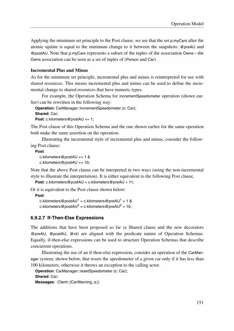
Operation Model
Applying the minimum set principle to the Post clause, we see that the set p.myCars after theatomic update is equal to the minimum change to it between the snapshots: @preAU and@postAU. Note that p.myCars represents a subset of the tuples of the association Owns—theOwns association can be seen as a set of tuples of (Person and Car).
Incremental Plus and MinusAs for the minimum set principle, incremental plus and minus is reinterpreted for use withshared resources. This means incremental plus and minus can be used to define the incre-mental change to shared resources that have numeric types.
For example, the Operation Schema for incrementSpeedometer operation (shown ear-lier) can be rewritten in the following way:
Operation: CarManager::incrementSpeedometer (c: Car);Shared: Car;Post: c.kilometers@postAU += 1;
The Post clause of this Operation Schema and the one shown earlier for the same operationboth make the same assertion on the operation.
Illustrating the incremental style of incremental plus and minus, consider the follow-ing Post clause:
Post:c.kilometers@postAU += 1 &c.kilometers@postAU += 10;
Note that the above Post clause can be interpreted in two ways (using the non-incrementalstyle to illustrate the interpretation). It is either equivalent to the following Post clause,
Post: c.kilometers@postAU = c.kilometers@preAU + 11;
Or it is equivalent to the Post clause shown below:Post:
c.kilometers@postAU1 = c.kilometers@preAU1 + 1 &c.kilometers@postAU2 = c.kilometers@preAU2 + 10;
6.9.2.7 If-Then-Else Expressions
The additions that have been proposed so far (a Shared clause and the new decorators@preAU, @postAU, @rd) are aligned with the predicate nature of Operation Schemas.Equally, if-then-else expressions can be used to structure Operation Schemas that describeconcurrent operations.
Illustrating the use of an if-then-else expression, consider an operation of the CarMan-
ager system, shown below, that resets the speedometer of a given car only if it has less than100 kilometers, otherwise it throws an exception to the calling actor.
Operation: CarManager::resetSpeedometer (c: Car);Shared: Car;Messages: Client::{CarWarning_e;};
151

Operation Schemas for Specifying Concurrent Operations
New: stopTampering: CarWarning_e;Post:
if c.kilometers@preAU < 100 thenc.kilometers@postAU = 0
elsestopTampering.oclIsNew ((reason => Reason::tamperingWithSpeedo, car => c)) &sender.sent (stopTampering)
endif;
The Post clause asserts that the car’s kilometer attribute is set to zero if it had a value of lessthan 100 immediately before it was updated, otherwise a warning message was sent to thecaller of this operation (sender) instead. Note that in a system where operations can executeconcurrently, the output message queue of the system can also be a shared resource. There-fore, I propose that the output message queue is implicitly constrained to be atomicallyupdated in all Operation Schemas that describe concurrent operations. As a consequence,the sent shorthand can be used in the usual way, as shown above. I discuss further the use ofshared resources and shorthands in section 6.9.2.10.
Care should be taken not to confuse if-then-else expressions with if-then-else state-ments like those found in imperative programming languages. To emphasize that an if-then-else expression is simply a predicate, below, I show the above Post clause rewritten usingimplies expressions:
Post:c.kilometers@preAU < 100 implies c.kilometers@postAU = 0 ¬ (c.kilometers@preAU < 100) implies stopTampering.oclIsNew...;
Explaining the above Post clause in more detail: an atomic update on the kilometers attributeof car c is only performed in the case that the snapshot of the resource denoted by the@preAU decorator has a value of less than 100. In the case that the snapshot of the resourcehas a value of 100 or more, a warning message was sent to the sender. Note that the @preAU
decorator denotes a snapshot of the value of the respective resource at the moment thatwould correspond to immediately before the update of the resource, if and only if the updateis judged necessary. Also, note that the related-snapshots convention is not needed, becauseat most one update is implied by the Post clause to the resource denoted by the expressionc.kilometers.
If-Then-Elsif-Else ExpressionsIt is also possible to use if-then-elsif-else expressions for describing multi-branch expres-sions. For example, the CarManager system could have an operation that allocates credit to aparticular person, where the amount given depends on the balance of the person. An Opera-tion Schema for the giveCreditPayout operation is shown below.
Operation: CarManager::giveCreditPayout (p: Person);Shared: Person;Post:
152
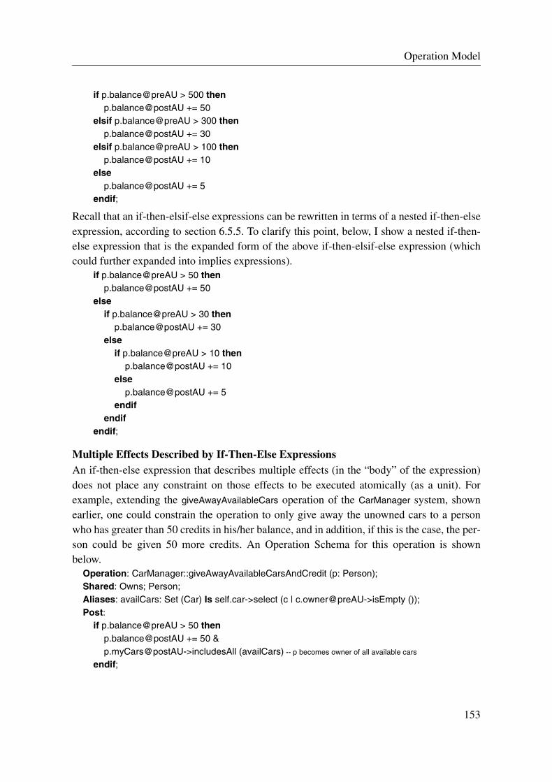
Operation Model
if p.balance@preAU > 500 thenp.balance@postAU += 50
elsif p.balance@preAU > 300 thenp.balance@postAU += 30
elsif p.balance@preAU > 100 thenp.balance@postAU += 10
elsep.balance@postAU += 5
endif;
Recall that an if-then-elsif-else expressions can be rewritten in terms of a nested if-then-elseexpression, according to section 6.5.5. To clarify this point, below, I show a nested if-then-else expression that is the expanded form of the above if-then-elsif-else expression (whichcould further expanded into implies expressions).
if p.balance@preAU > 50 thenp.balance@postAU += 50
elseif p.balance@preAU > 30 then
p.balance@postAU += 30else
if p.balance@preAU > 10 thenp.balance@postAU += 10
elsep.balance@postAU += 5
endifendif
endif;
Multiple Effects Described by If-Then-Else ExpressionsAn if-then-else expression that describes multiple effects (in the “body” of the expression)does not place any constraint on those effects to be executed atomically (as a unit). Forexample, extending the giveAwayAvailableCars operation of the CarManager system, shownearlier, one could constrain the operation to only give away the unowned cars to a personwho has greater than 50 credits in his/her balance, and in addition, if this is the case, the per-son could be given 50 more credits. An Operation Schema for this operation is shownbelow.
Operation: CarManager::giveAwayAvailableCarsAndCredit (p: Person);Shared: Owns; Person;Aliases: availCars: Set (Car) Is self.car->select (c | c.owner@preAU->isEmpty ());Post:
if p.balance@preAU > 50 thenp.balance@postAU += 50 &p.myCars@postAU->includesAll (availCars) -- p becomes owner of all available cars
endif;
153
Operation Schemas for Specifying Concurrent Operations
In the above Post clause, the then-part of the if-then-else expression defines two effects:adding 50 credits to p’s balance and making p the owner of all unowned cars of thatmoment. Due to the predicate nature of the Post clause and the absence of order for con-junction, the time at which p’s balance is updated is independent of the time at which p ismade owner of the available cars, i.e., there is no temporal relationship between the execu-tions of the effects. Clearly, in terms of implementation, it is unlikely that one would chooseto allocate the car before the balance could be guaranteed, but the point to make is that logi-cal-and does not impose order.
In some situations, it is necessary to constrain different effects to be executed as acombined update that is seen as an atomic action from the exterior (i.e., other operations).This issue is discussed in section 6.9.2.9.
If-Conditions that Include “@postAU” DecoratorsAn if-condition of an if-then-else expression may include expressions that have the @pos-
tAU or @rd decorators postfixed. Illustrating the use of the @postAU decorator in an if-con-dition, one could elaborate on the incrementSpeedometer operation, shown earlier, by takinginto account the effect that incrementing the kilometers of a car can have on the deprecationlevel of the car. The revised Operation Schema for the incrementSpeedometer operation thattakes into account these aspects is shown below.
Operation: CarManager::incrementSpeedometer_V2 (c: Car);Shared: Car;Post:
c.kilometers@postAU += 1 &if [email protected] (10000) = 0 then --mod (i.e., modulo) is a prefined (numeric) operator in OCL
c.deprecationLevel@postAU += 1endif;
The Post clause makes use of the @postAU snapshot of the kilometers attributes to make anassertion about the necessary change to the deprecationLevel attribute of the car objectparameter. The if-condition imposes a pseudo-ordering constraint. I use the term pseudo-ordering constraint, because it does not impose upon the implementation the requirement torealize the update in the order: increment the kilometers attribute, and then increment thedeprecationLevel attribute (if necessary), however, this order would be the most usual inter-pretation1. Note that it would be inappropriate to use an @rd decorator instead, because thissnapshot could be taken at any time of the operation—having no relationship to the @pos-
tAU snapshot of the kilometers attribute.
1. It would be equally possible to have an implementation that performs the effects in the other order and thencheck after the increment to kilometers whether it needs to roll back the increment to deprecationLevel.However, this choice of implementation would be unusual, and it would make little sense for this example.
154

Operation Model
If-Conditions that Include @rd DecoratorsIllustrating the use of the @rd decorator in an if-condition, one could elaborate on the give-
AwayAvailableCars operation of the CarManager system, shown earlier, by ensuring that per-son p is only given the unowned cars if s/he has a premier driving class.
Operation: CarManager::giveAwayAvailableCars_V2 (p: Person);Shared: Owns; Person;Aliases: availCars: Set (Car) Is self.car->select (c | c.owner@preAU->isEmpty ());Post:
if p.drivingClass@rd = DClass::premier thenp.myCars@postAU->includesAll (availCars)
endif;
The use of the @rd decorator in the if-condition of the Post clause poses an interesting prob-lem. What happens if the time that the snapshot is taken of the corresponding sharedresource (i.e., the one denoted by the expression with the @rd decorator) does not coincidewith the time that the effect implied by the then-part is performed?
Recall that an if-then-else is just a logical expression and no ordering is impliedbetween the conditions and effects, unless constrained otherwise. In this example, we can-not know at which time the snapshot of the expression p.drivingClass is taken because thereis no constraint relating the @rd snapshot to the update. Concretely, say the operation startsat time 0 and the atomic update made to the resource denoted by p.myCars is performed attime 2, then the operation would still fulfill the Post clause if say the read of the resourcedenoted by p.drivingClass@rd is taken at time 5. Using @rd decorators in if-conditions cantherefore be misleading if one interprets the condition as a guard, as in procedural program-ming languages.
Clearly, the if-then-else expression, shown above, is not very useful if one can notguarantee that the if-condition is true at the time of the update. For instance in this example,the desired interpretation would be to only allow the person p to become owner of theunowned cars stored by the system if p had a driving class of premier at the time of the carallocation. Rather than making use of the related-snapshots convention, a new kind ofexpression is proposed in the next subsection for the purpose of addressing this issue and anumber of other ones too.
Possible Ways to Realize If-Then-Else ExpressionsAn if-then-else expression does not constrain the designers to either immediate or waitsemantics on the condition, i.e., whether the operation should wait on the if-condition tobecome true or whether the if-condition should be evaluated immediately.
For example, the following Operation Schema describes an operation that allocates acar c to a person p if p does not already own 5 cars or more.
Operation: CarManager::allocateCar (p: Person, c: Car);Shared: Owns;Post:
155
Operation Schemas for Specifying Concurrent Operations
if p.myCars@preAU->size () < 5 thenp.myCars@postAU->includes (c)
endif;
An implementation of this Operation Schema could immediately evaluate whether p hasless than 5 cars and then allocate c to p given that it was the case, and if not, do nothing(else-part is true). Equally, an implementation could wait on the condition to become trueand then perform the allocation when it becomes true. Both possibilities are valid refine-ments of the Operation Schema.
Note that an operation may be constrained to terminate execution within a certaintime period due to performance constraints (see Chapter 7 for information on describingtiming constraints using an ANZAC specification). Furthermore, according to the correct-ness rule expressed by an Operation Schema, the operation must eventually terminate, andtherefore an operation is not allowed to wait on a condition forever. So the underlyingsemantics requires that the operation waits on the condition to become true for x time units,where x is a natural number, which includes zero (the immediate case) and any number thatis not infinite (the wait cases).
6.9.2.8 Rely Expressions
In concurrent systems, it is often necessary to define the synchronization dependencies onshared resources between operations. As we have seen with the use of if-then-else expres-sions in the previous subsection, it is not possible to express some kinds of synchronizationconstraints.
In some situations, it would be useful to be able to describe conditions that could berelied upon to stay true during the fulfillment of an effect, i.e., for the effect to be valid. Forthis purpose, I introduce a new kind of expression called a rely expression, which has simi-larities to the concept of a rely-condition, first introduced by Jones1 [Jon83], and it offersthe possibility to express a number of synchronization constraints that are not possible toexpress using if-then-else expressions.
A rely expression declares a condition, called the rely-condition2, and two effects, onecalled the rely-effect and the other one called the fail-effect. The form of a rely expression isthe following:
rely rely-condition thenrely-effect
failfail-effect
endre;
1. For an overview of rely-/guarantee-conditions see Chapter 2.2. Note that the rely-condition of rely expression has a different meaning to the one proposed by Jones; there-
fore, they should not be confused.
156

Operation Model
The meaning of the rely expression is that there is an obligation on the operation to fulfillthe rely-effect (i.e., the boolean expression must be made true by operation) if and only ifthe rely-condition is observed (i.e., the boolean expression stays true) by all other activities1
during the rely-effect fulfillment period. If there exists a moment during this period suchthat the rely-condition fails (i.e., the boolean expression becomes false), then there is anobligation on the operation to fulfill the fail-effect. In other words, any change to the systemstate by any other operation over the period of execution of the rely-effect is supposed tosatisfy the rely-condition, but, if it can not be satisfied, then the operation is obligated tocarry out the fail-effect instead.
It is important to stress that the rely-condition has (timing) scope only over the periodthat the corresponding effect is being carried out and not the period of the whole operation.It is also important to stress that the rely-condition is “evaluated” with respect to changes ofsystem state made by all other operations, i.e., it does not constrain the one being describedby the Operation Schema.
The syntax for the rely expression is the following:rely-expression = “rely” rely-condition “then” boolean-effect-expression
[ “fail” boolean-effect-expression ] “endre”
A rely expression has a similar form to an if-then-else expression.Illustrating a rely expression in an Operation Schema, consider an operation of the
CarManager system that allocates a car to a person only if it can be relied upon that theselected person has less than 10 credits in his/her account during the allocation of the car tothe person. The Operation Schema for this operation could be written in the following way:
Operation: CarManager::allocateCar_V2 (p: Person, c: Car);Shared: Owns; Person;Post:
rely p.balance < 10 thenp.myCars@postAU->includes (c)
failtrue
endre &-- other effects...;
The rely expression (of the above Post clause) ensures that if person p was given a car c thenthe condition that p had less than 10 credits in his/her balance was held true by all otheroperations immediately before, during, and immediately after the car allocation was carriedout, otherwise the rely expression obliges no effect to take place (i.e., the fail-effect is true).Note that a rely expression always has a fail-effect. However, in the cases that it is just“true”, it may be omitted from the text, where the implication is that all rely expressions thatdo not express a fail-effect assert that there is no effect, i.e., the fail-effect expression is
1. those ones other than the one executing the corresponding operation
157

Operation Schemas for Specifying Concurrent Operations
equivalent to true. For instance, the above rely expression could be rewritten in the follow-ing way and it would have the same meaning:
rely p.balance < 10 thenp.myCars@postAU->includes (c)
endre
Time WindowIt is important to note that the rely-condition does not necessarily need to hold true duringthe whole execution of the operation, but only during the period that its encapsulated rely-effect is being carried out. This would mean that while “other effects” are being carried out,the rely-condition may or may not hold true without consequence on the evaluation of therely expression. In other words, the rely-condition of the above Post clause may only be true(i.e., p has less than 10 credits) for a small window of time during the operation’s executionperiod, but as long as p was added as owner of c within this time window, the rely-effectmust be satisfied.
Consider the following Post clause, which expresses two disjoint rely-conditions oftwo rely expressions.
Post:rely p.balance < 10 then
p.myCars@postAU->includes (c)endre &rely p.balance > 10 then
p.drivingClass@postAU = DClass::premierendre;
The rely expressions in the above Post clause do no contradict each other. Rather theyensure that when their respective (encapsulated) effects are carried out that their respectiverely-conditions are held true by all other operations, otherwise no obligation is placed on theoperation to do anything. The usefulness of an operation that fulfills the above Post clausemay be questionable, but it nevertheless makes the point.
Rely-Conditions Do Not Have DecoratorsAs a rule, expressions in the rely-condition of a rely expression do not have any decorators(i.e., @rd, @preAU, @postAU), because the rely-condition does not denote a single snapshotof the respective resources, like it would for an if-condition. (Theoretically, using a continu-ous model of time, it would mean that an infinite number of snapshots would be taken overthe period that the effect is carried out. But clearly this could be loosened to all snapshots ofeach micro-state change on the system, or even just the changes to the resource in question).
Relating Rely Expressions to If-Then-Else ExpressionsIn some cases, a rely expression may define the same effect as an if-then-else expression.For example, the two expressions below have equivalent effects.
158

Operation Model
rely p.myCars->size () < 10 thenp.myCars@postAU->includes (c)
endre----if p.myCars@preAU->size () < 10 then
p.myCars@postAU->includes (c)endif
The if-then-else expression has the same effect as the rely expression, because it takesadvantage of the fact that the change defined in the then-part is the only change that can bemade over the period of the update (because it is forcibly atomic). It is a matter of style as towhether one uses a rely expression or an if-then-else expression in those cases when it ispossible to use both. However, in order to avoid redundancy, I strongly recommend that therely expression be chosen in preference to the if-then-else expression. The reason is simple:rely expressions give the immediate impression that one is dealing with shared resources(if-then-else expressions, on the other hand, can be used for both shared and non-sharedresources, so the distinction is not as clear).
The recommendation is stated in the form of a guideline, and it is observed by allexamples given in the rest of this thesis.
Guideline 1: All if-conditions of if-then-else expressions that use the @preAU and @rd snapshots should be replaced by rely-expressions.
The only time that I make an exception to this guideline is when multiple branches arerequired—often needed to differentiate failure cases. In this case, an if-then-elsif-elseexpressions should be used. In fact, this points out a limitation of rely-expressions: there isno way to enumerate failure cases1.
Applying a rely expression to the giveAwayAvailableCars_V2 operation from the previ-ous subsection, which posed some problems for describing with if-then-else expressions,we get the following Operation Schema.
Operation: CarManager::giveAwayAvailableCars_V2 (p: Person);Shared: Owns; Person;Aliases: availCars: Set (Car) Is self.car->select (c | c.owner@preAU->isEmpty ());Post:
rely p.drivingClass = DClass::premier thenp.myCars@postAU->includesAll (availCars)
endre;
For the above Post clause, the rely expression ensures that the car allocation is made only inthe case that p’s driving class is premier and stays that way during the fulfillment of the allo-cation, otherwise no allocation is ensured.
1. The semantics for such an extension (i.e., enumerated rely expressions) is quite tricky, and consequently,enumerated rely expressions are not addressed by this work.
159

Operation Schemas for Specifying Concurrent Operations
Fail-Part of Rely ExpressionsThe fail-part of a rely expression is obligated to hold only if the rely-condition fails to holdover the period of rely-effect fulfilment. To illustrate a rely expression with a meaningfulfail-part, consider an elaborated version of the Operation Schema for the allocateCar opera-tion, shown below.
Operation: CarManager::allocateCar_V3 (p: Person, c: Car, boss: Person);Shared: Owns; Person;Post:
rely p.myCars->size () < 10 and p.balance < 100 thenp.myCars@postAU->includes (c)
failboss.myCars@postAU->includes (c)
endre;
The fail-part of the rely expression is interpreted in the following way: if all the other ongo-ing operations fail to keep person p’s number of cars below 10 and its balance under 100credits immediately before, during, and after the car allocation, then the boss will receivethe car instead.
Negation IssuesDue to the “during” aspect of rely expressions, negation of a rely expression does not followthe same rules as it does for if-then-else expressions. For example, the following relyexpression is not logically equivalent to the one below it:
rely john.balance > 0 thenjohn.drivingClass@postAU = DClass::premier
failjohn.drivingClass@postAU = DClass::second
endre
rely not (john.balance > 0) then -- i.e., john.balance <= 0
john.drivingClass@postAU = DClass::secondfail
john.drivingClass@postAU = DClass::premierendre
The problem relates to the fact that the condition is not evaluated at a single time but manytimes over the fulfillment period of effect. Thus, the effect of negating a rely condition is toapply negation to each evaluation during the period.
Possible Ways to Realize Rely ExpressionsSimilarly to if-then-else expressions, rely expressions do not constrain the designers toeither immediate or wait semantics on the rely-condition, i.e., whether the operation shouldwait on the rely-condition to become true or whether the rely-condition should be evaluatedimmediately.
160

Operation Model
For instance, an implemented operation that does a wait until the condition becomestrue (assuming it will become true) and then tries to execute the code that would correspondto the body of the rely expression, rolling back if the rely-condition fails to hold during exe-cution (where it would be obligated to fulfil the fail-effect instead), is a valid refinement.Equally, an implemented operation that immediately tries to carry out the rely-effect andfails if the rely-condition is initially false is also a valid refinement, because the rely-condi-tion could not be held during the rely-effect fulfillment period.
This means that the starting time of carrying out the rely-effect of a rely expressioncan be seen as a “parameter” (a natural number of time units) of the expression. Relyexpressions at the Operation Schema level abstract above a particular value for this parame-ter, and thus, by refinement, an implementation can specialize this parameter to a particularvalue (or range of values).
Another “parameter” of a rely expression that is abstracted above at the OperationSchema level is the number of attempts that can be made by the operation to fulfill the rely-effect. This means that the rely expression at the Operation Schema level does not restrict animplementation from making several attempts and associated rollbacks (in the transactionalsense of the word). It does however require that the postcondition be established on termina-tion of the operation (an obligation). In the case that the rely-effect is fulfilled, the rely-con-dition must have held during the fulfillment period of the last attempt (which may equallyhave been the first and only one). In the case that the fail-effect is fulfilled, the rely-condi-tion must have became false at some time during the fulfillment period of the rely-effect forall attempts.
Possible Analyses that Could Be Performed on Rely ExpressionsBy analyzing the properties used in the rely-conditions, it may be possible to provide somehints to designers: whether immediate or wait semantics may be preferable, whether oncethe rely-condition becomes false it will stay that way from thereon, or whether once therely-condition becomes true it will stay that way from thereon.
To provide an example of the last case, consider a rely expression that asserts an effectof buying popcorn only if it can be relied upon that a rugby match does not finish before thepopcorn has been bought. If the rugby match object has an attribute finished, then one coulddescribe the situation with the following rely expression:
rely not allblackMatch.finished thenbuyPopcorn_p (2);
endre
In this case, it is possible to reason that once allblackMatch.finished becomes true it will staythat way from thereon, since a particular rugby match will only ever occur once. Therefore,in design terms, it would be pointless to use a mechanism that waits for such a condition tobecome true if it were already false.
161

Operation Schemas for Specifying Concurrent Operations
Being able to supply such information would assist the designers to choose appropri-ate control mechanisms to use. However, techniques to conduct an analysis of the rely-con-ditions are not discussed any further in this chapter; they are a possible area for future work.
6.9.2.9 Atomicity of Effects
In some situations, it is necessary to constrain several effects to be executed atomically fromthe point of view of the exterior (i.e., from the perspective of other system operations). Tak-ing an example based on the CarManager system, consider an operation that exchanges carownership between a buying and selling person, and that ensures that the appropriate fundsare also exchanged between them. The exchange is fulfilled if it can be relied upon that thebuyer has sufficient funds and s/he does not already have a car. An Operation Schema forthis operation is shown below.
Operation: CarManager::exchangeOwnership (buyer: Person, seller: Person, c: Car);Shared: Owns; Person;Post:
rely buyer.balance >= c.price and buyer.myCars->isEmpty () thenbuyer.balance@postAU -= c.price & -- note that c.price is not a shared resource
seller.balance@postAU += c.price &buyer.myCars@postAU->includes (c) &seller.myCars@postAU->excludes (c)
endre;
The interpretation of the above Post clause does not require the balance of the buyer andseller to be updated in unison, i.e., it is not required to be performed as a combined atomicaction, and similarly for the exchange of ownership. Basically, the four atomic updates maytake effect at different stages of the operation, and therefore each one is possibly visible tothe exterior as four separate changes to the state of the system.
Taking the case when four separate updates are visible to the exterior, a problem ariseswhen other operations make use of information about the state of the system while thisoperation is still executing. To illustrate the problem, consider a periodically executed oper-ation of the CarManager system that checks to see if the system has over 100 car owners, andif so, it gives the system a bonus point. An Operation Schema for this operation is shownbelow.
Operation: CarManager::applyBonus ();Shared: Owns; CarManager;Aliases: numOfCarOwnersInSystem: Boolean Is self.car.owners->asSet ()->size ();Post:
rely numOfCarOwnersInSystem > 100 thenself.bonus@postAU += 1
endif;
To highlight the problem, take the situation where the exchangeOwnership operation startedto execute with the system containing 100 different owners, and it has just added the tuple
162

Operation Model
(buyer, c) to the Owns association, but the operation has not yet removed the tuple (seller, c)from the association. At this moment, the applyBonus operation is executed and the expres-sion numOfCarOwnersInSystem is evaluated. In this situation, it would evaluate to 101, andthe system would unrightfully receive a bonus point. Equally, in the case where the removalis executed before the addition then the system could be not given a bonus point that it infact deserved.
Note that another reason why this behavior is erroneous is because the multiplicity ofthe association end role owner would be equal to 2 at the time of executing the applyBonus
operation. Therefore the actual multiplicity is outside of the required 0..1 range (specified infigure 6.4). Recall that all invariants are evaluated at the pre- and post-execution time of theoperations. In this case, the assumptions of the applyBonus operation would fail.
This problem highlights the necessity of combined updates that are seen as atomicfrom the perspective of other concurrently executing operations. For the exchangeOwnership
operation, it is necessary that the exchange of ownership be visible to other operations as anatomic action, and similarly for the exchange of funds. Therefore, one needs to be able toexplicitly capture those effects described by the Post clause that should be combined toform a single atomic, compound effect.
Atomic Compound-EffectsThe @preAU and @postAU decorators provide a good base for defining such a constraint,because they refer to the value of the corresponding resource immediately before and afterthe atomic update, respectively. Thus, if the time at which the @preAU snapshot of theresource is taken is the same as the time at which the @preAU snapshot of another resourceis taken, and equally for their @postAU snapshots, then the two effects described are anatomic compound-effect.
Providing a notation to describe an atomic compound-effect constraint, I propose asmall modification to the @preAU and @postAU decorators of the corresponding expres-sions. As a convention for this constraint, the @preAU and @postAU decorators become@preACU and @postACU, respectively. For instance, if exprX and exprY refer to tworesources that are updated atomically, then exprX@preACU is a snapshot that is constrainedto be taken at the same time as exprY@preACU, and equally for @postAU snapshots, i.e.,exprX@postACU is “snapped” at the same time exprY@postACU. Note that the ‘C’ stands forcompound, and thus, “ACU” stands for Atomic Compound-Update.
In the case that there are two or more different atomic compound-effects, the number-ing scheme of the related-snapshots convention is used to differentiate them, i.e., @preACU#
and @postACU#, respectively, where the # is a number that is used to match common “par-ticipants” of an atomic compound-effect. For example, exprA@preACU1 and exprB@preACU2
are part of expressions denoting different atomic compound-effects.With respect to the example from above, one can rewrite the Post clause in the follow-
ing way to take into account the proposed convention.
163

Operation Schemas for Specifying Concurrent Operations
Post:rely buyer.balance >= c.price and buyer.myCars->size () < 10 then
buyer.balance@postACU1 -= c.price &seller.balance@postACU1 += c.price &buyer.myCars@postACU2->includes (c) &seller.myCars@postACU2->excludes (c)
endre;
The above Post clause asserts that, if the rely-condition holds true, then the exchange offunds between the buyer and seller is an atomic action and the exchange of cars between thebuyer and seller is also an atomic action.
Note that it would have been equally possible to define the four updates as a singleatomic compound-update. Clearly, the choice of which granularity of atomic update tomake depends on the “other” operations that can execute concurrently to the one beingspecified, where the decision is made by working out what we can allow them to see.
To clarify further the use of the atomic compound-effect convention, I show anotherexample of an operation that needs to ensure that a compound effect is carried out atomi-cally; the Operation Schema for this operation is shown below. It describes the bossLosesBet
operation of the CarManager system that transfers a certain amount of credit from the boss’balance to each of the employee’s balances. However, transfers of bet winnings are onlyallowed if the system has more than 100 bonus points and the boss has sufficient credit. Themeaning of the operation is that the boss lost a bet to his/her employees and thus must paythem out1, but s/he is exempt if either the system bonus cannot be relied upon to stay over100 points or s/he does not have sufficient funds.
Operation: CarManager::bossLosesBet (boss: Person, employees: Set (Person), bet: Credit);Shared: Owns; Person;Messages: Client::{NoPayOut;};New: bossSaved: NoPayOut;Aliases: totalPayOutAmount: Credit Is bet * employees->size ();Pre: self.person->includesAll (employees->including (boss));Post:
rely self.bonus > 100 and boss.balance >= totalPayOutAmount thenemployees->forall (e | -- for each employee
boss.balance@postACU -= bet & -- asserts that bet amount is taken from boss’ balance
e.balance@postACU += bet ) -- asserts that bet amount is put on employee’s balance
failbossSaved.oclIsNew () &sender.sent (bossSaved)
endre;
The Post clause makes use of the ACU convention to indicate that the transfer from the boss’balance to the employees’ balances is an atomic compound-effect. In addition, note that by
1. Clearly, one could generalize this operation to “person loses bet” but that would not be as interesting!
164

Operation Model
using increment minus (-=) to indicate the incremental change to the boss’ balance, one isable to express the relationship between the decrement of the boss’ balance and the incre-ment of each employee’s balance. The other option would have been to write the following:
boss.balance@postACU -= totalPayOutAmountemployees->forall (e | e.balance@postACU += bet )
However, this form gives a less intuitive understanding of the relationship between thecredit taken from the boss’ balance and the credit placed on each employee’s balance.
6.9.2.10 Shorthands and Parameterized Predicates that Use Shared Resources
To facilitate the writing of concurrent operations using Operation Schemas, it should bepossible to use shared resources with shorthands and Parameterized Predicates without hav-ing to expand them. I now make some proposals in relation to shorthands and ParameterizedPredicates with respect to atomic updates and atomic compound-updates.
Shorthands and Atomic UpdatesI propose that the oclIsNew property can be used without concern for whether the resource isshared or not. This means that if the oclIsNew property of a shared resource is used in thePost clause of an Operation Schema, then it is true if and only if the corresponding resourcewas atomically added to the system as a result of the operation. Note that this notion of“shared” is somewhat artificial due to the way creation is modelled in Operation Schemas.
Using message creation as an example, the following expression:msgA.oclIsNew ((p1 => a1))
is equivalent to the following one:MessageA.allInstances@postAU->includes (msgA) & msgA.all = (p1 => a1)
given the following declaration:Messages: ActorX::{MessageA;}; New: msgA: MessageA;
As discussed in section 6.9.2.7, the output message queue is implicitly constrained to beatomically updated in all Operation Schemas that describe concurrent operations. Thismeans that the sent shorthand asserts that the output queue of the system is atomicallyupdated by the operation. For example, the following expression:
actorX.sent (msgA)
can be expanded to the following expression:self.outMessages@postAU->one (m | m = msgA) & -- from sent
msgA.destination@postAU = Set {actorX}; -- from sent
Shorthands and Parameterized Predicates as Part of Atomic Compound-EffectsIn specifying atomic compound-effects using Operation Schemas, it can be useful toinclude a shorthand or Parameterized Predicate expression as part of the compound-effect.For the purpose of explicitly showing that a shorthand or Parameterized Predicate expres-
165

Issues and Remarks
sion is part of an atomic compound-effect, I propose to use the following convention: the’ACU decorator is postfixed to the target expression.
To illustrate this convention, consider the following Operation Schema, whichdescribes an operation that fixes the price of the car, modifies the car to make it more desir-able, and informs the client and the dealer as to the price of the car. Furthermore, it isassumed that this operation needs to be executed as a single atomic compound-effect.
Operation: CarManager::queryMadeOnCar (c: Car, p: Person; amount: Credit);Shared: Car;Messages: Client::{NewPrice;}; Dealer::{NewPrice;};New: msg1, msg2: NewPrice;Post:
c.price@postACU = amount &changeCarDetails_p (c)’ACU;msg1.oclIsNew ((price => amount, comment => “What a Good Buy!”))’ACU &p.client.sent (msg1)’ACU &msg2.oclIsNew ((price => amount, comment => “Another Sucker!”))’ACU &sender.sent (msg2)’ACU;
The Post clause makes use of the ’ACU decorator to indicate that all effects are carried outatomically. The Parameterized Predicate that is used on the second line is defined below.
Predicate: CarManager::changeCarDetails_p (car: Car);Body:
car.deprecationLevel@postAU = IClass::lowest &rely car.kilometers > 10E5 then
car.kilometers@postAU = 10E5endre;
Note that the ’ACU decorator would mean that each @preAU and @postAU decorator of thisParameterized Predicate is transformed into a @preACU and @postACU, respectively.
It is also possible to use the numbering scheme of the related-snapshots conventiontogether with the ’ACU decorator convention.
6.9.3 Issues and Remarks
In general, the extensions that were proposed in this section for specifying concurrent oper-ations match the declarative style of the Operation Schemas proposed in section 6.2 throughsection 6.8. However, I admit that the introduction of additional language constructs forenforcing synchronization constraints makes the approach considerably more complicated.Furthermore, these additional language constructs give the specifier more power to “shootthemselves in the foot” when writing Operation Schemas, because it is easier to write Postclauses that do not make sense or that exhibit obscure contradictions. It is also clear thatperforming any kind of formal analysis to “concurrent” Operation Schemas would be con-siderably more difficult than for the sequential versions. However, this is not unusual
166

Operation Model
because concurrent software systems are considered to be more difficult to develop and rea-son about than sequential software systems [Mas98].
The ’ACU decorator convention provides a means for describing atomic compound-effects. However, I do not provide any rules or guidelines for helping specifiers to find can-didate groups of effects that could form atomic compound-effects. When consideringwhether a group of effects should be executed atomically or not, it can be useful to look atthe invariants of the system. In general, effects should be combined to form an atomic com-pound-effect if they break an invariant as individual atomic effects, as was shown in the caseof the Operation Schema for the exchangeOwnership operation (section 6.9.2.9). The devel-opment of a comprehensive set of rules and guidelines would be a possible area for futurework.
Rely expressions as they stand are able to define only two cases: success and failure.A useful enhancement would be to allow the enumeration of the different fail cases in relyexpressions—in much the same way as it is possible to use elsif parts in an if-then-elseexpression for this purpose. Such a facility would allow one to be more precise in dealingwith failure.
Another idea for an expression that I believe could be useful is one that constrains ashared resource to stay unchanged during the execution of an effect. Such an expressionwould have a similar form and meaning as a rely expression, except it would be subtly dif-ferent, because it would impose a no-change rule, and it would not allow failure, as relyexpressions do. Clearly, in the case that shared resources are updated, such a (conceptual)mechanism is already more or less available—all shared resources are only changed by thecontrolling operation during the period of their updates. However, for shared resources thatare read rather than changed and where one must guarantee that they stay unchanged overthe period of an atomic compound-update, an expression that defines such a constraintwould be useful.
6.10 Example of an Operation Schema
In this section, I present an Operation Schema that describes an operation of an auction sys-tem for placing a bid. It highlights many of the different aspects of Operation Schema intro-duced in the preceding sections.
6.10.1 Background
This example is about placing bids in an electronic auction, which is controlled by a systemcalled AuctionManager. A bid represents a user’s intention to buy goods for a certain amountof money in the format of an English-style auction. In an English-style auction, the goodson auction are given a starting price which is, in theory, low enough to tempt other users
167

Concept Model for AuctionManager System
into bidding for the goods. Users can make as many bids as they wish until the auctioncloses. On closure, the highest bid is compared to the reserve price of the seller to see if thegoods are sold or not.
In this system, customers have credit with the system that is used as security on eachand every bid. Customers can increase their credit by asking the system to debit a certainamount from their credit card, and equally they can take their credit back by having it placedon their credit card. Also, customers can allow the system to automatically withdraw a cer-tain amount of money from their credit card at the moment that there is not enough moneyon their account when making a bid (i.e., the customer does not have sufficient funds tomake a bid).
Customers that wish to bid in an auction must first make a request to the system tojoin the auction; once joined, they can make as many bids as they wish, until the auctioncloses. Bidders are allowed to place their bids across as many auctions as they please. A bidis accepted if it is over the minimum bid increment (calculated purely on the amount of thehigh bid, e.g., 50 cent increments when bid is between $1-10, $1 increment between $10-50, etc.), and if the bidder has sufficient funds, i.e. the customer's credit with the system is atleast as high as the sum of all pending high bids (in all auctions) plus the bid amount pro-posed in that bid. This last constraint will guarantee that bids are always solvent. Note thatthis idea of solvent bids in the context of auctions comes from Kienzle [Kie01]. A completedescription of the AuctionManager system can be found at [Se02a].
6.10.2 Concept Model for AuctionManager System
To be able to describe the Operation Schema for the place bid operation, which I refer to asplaceBid, it is necessary to define the Concept Model for the AuctionManager system. TheConcept Model for the AuctionManager system is shown in figure 6.6.
It consists of six (normal) classes: Auction, FixedPeriodAuction, BidTimedAuction, Bid,Customer and Credit, and two <<rep>> classes: User and CreditInstitution. The system containsseven (non-composition) associations. The SellsIn and JoinedTo associations connect cus-tomers to the auctions that they sell goods in and that they are joined to, respectively. TheMakes association connects customers to their bids. The Has association connects customerto their credit account. The HasHighBid association is derived: it stands for a link between anauction and its highest bid.
The Auction class contains bids that are made for the goods on sale in the auction. Auc-
tion is an abstract class that has two subclasses: FixedPeriodAuction and BidTimedAuction.These two classes inherit all attributes and associations of Auction. FixedPeriodAuction signi-fies an auction that closes after a fixed time period and BidTimedAuction signifies an auctionthat closes only when a certain period has expired after the placement of the last bid.
Credit contains four attributes and one derived attribute: actualBalance represents theamount of credit that the associated customer has with the system. autoWithdraw is true if the
168

Operation Model
associated customer wishes to have the system automatically take money from his/her creditcard, so that it can be used for buying auctioned goods. autoWithdrawAmount is the amount ofmoney that is withdrawn when an auto-withdraw is performed. guaranteedBalance is aderived attribute, which is discussed below. Finally, creditDetails represents the informationneeded by a credit institution to perform a transfer into or out of the account of the associ-ated customer. The system also contains a similar attribute (with the same name), whichrepresents the information needed by a credit institution to perform a transfer into or out ofthe account of the enterprise owning the system.
The guaranteedBalance derived attribute is defined by the following invariant:context: Credit inv:
self.guaranteedBalance = self.actualBalance - self.customer.myBids->select (b |b.auctLeading->exists (a | not a.closed))->sum (amount)
The HasHighBid derived association is defined by the following two invariants:context: Auction inv:
self.highBid =if self.bid->notEmpty () then
self.bid->any (b | b.amount = self.bid.amount->max ())else
self.bid -- i.e., the empty set
endif;
The above invariant states that if there is at least one bid then the highBid of an auction (high-
Bid is one association-end role of the derived association HasHighBid) is equivalent to the bidthat has the maximum amount, otherwise highBid is equivalent to the empty set. Note that inOCL, a 0..1 association-end can be treated as a set or a single element.
Figure 6.6: Concept Model for AuctionManager system
0..1
0..*
0..1
JoinedTo
1
0..*
0..*
bidder
Bid
amount:Money
Makes
CreditcreditDetails: CreditInfoactualBalance: Money/guaranteedBalance: MoneyautoWithdraw: BooleanautoWithdrawAmount: Money
Has1
CustomerstartingDate: DatestartingPrice: MoneyreservePrice:Moneydescription: GoodsInfostarted: Booleanclosed: Boolean
details:CustomerInfologgedOn:Boolean
<<rep>>User
11
AuctionManager<<system>>
/ HasHighBid
Auction
creditDetails: CreditInfocurrentDate: Date
myBids
currentMbrsjoinedAuctions
institution<<rep>>
CreditInstitutionFixedPeriodAuction
duration:Period
BidTimedAuction
maxBidPause:Period
1
1
highBid
auctLeading
0..*
1SellsIn0..*sellermyAuctions
ArePlacedIn1
1
169

Operation Schema for placeBid Operation
The invariant, below, states that the auctLeading of a bid (the other association-end role ofthe derived association HasHighBid) is equivalent to its containing auction (ArePlacedIn com-position association).
context: Bid inv:self.auctLeading = self.auction;
The system has a number of state invariants. One of these invariants (which is relevant to theplaceBid operation) is allPositiveBalancesForCusts. It is described using OCL, below.
context: Credit inv allPositiveBalancesForCusts:self.actualBalance >= 0;
The above invariant states that all (actual) customer balances must stay above zero.
6.10.3 Operation Schema for placeBid Operation
The placeBid operation represents the intention of a user to place a bid in a certain auction.This operation is responsible for determining whether the bid is valid or not. If it is valid,then the operation ensures that the bid of the user is placed in the target auction.
Concurrency and Feature InteractionA placeBid operation can execute concurrently to a number of other operations. Of theseoperations, only some of them share resources with this operation. These include other pla-
ceBid operations of different users placing bids in the same auction, operations that changethe credit of the calling user, and any operation that closes the auction. Usually, the informa-tion on which operations can perform concurrently to each other is provided by the ProtocolModel. The Protocol Model is presented in the next chapter.
An interesting feature of the AuctionManager system is the auto-withdrawal option forusers. This feature allows the system to augment the requesting user’s credit in the systemby a pre-defined amount (an amount previously agreed upon by the user) whenever the userattempts to place a bid that would not otherwise be solvent. Therefore, by performing theauto-withdraw within the execution of the placeBid operation, the user may thereafter havesufficient funds to place that bid. Note that this is an example of desirable feature interaction(the term was introduced in Chapter 3), where the auto-withdraw feature is said to interactwith the place bid feature.
In terms of concurrency, the auto-withdrawal feature for a user is either turned on oroff during the execution of any placeBid operation for the user, and therefore, the operationfor switching the option on or off cannot execute concurrently to any placeBid operation ofthe user.
placeBid Operation SchemaFigure 6.7 shows the Operation Schema for placeBid. It takes as parameters an auction a, acustomer c, and a bid amount bidAmount. The Shared clause shows that the operation
170

Operation Model
accesses the following shared resources: one or more attributes of objects of the Credit andAuction classes, the Makes and HighBid associations, and the ArePlacedIn composition associ-ation. The Messages clause shows that the operation may (synchronously) call the CreditInstitution using a transfer message. This call can throw an exception, RequestFailure_e.Also, in the case that the system judges the bid to be invalid, the system sends anInvalidBid_e Exception to the user. The Pre clause asserts that the customer c is a member ofthe auction a and that the auction has already started. The most complicated part of the pla-
ceBid operation is the Post clause.
Figure 6.7: Operation Schema for placeBid
Operation: AuctionManager::placeBid (a: Auction, c: Customer, bidAmount: Money);Description: A user requests to place a bid in the given auction: the system must decidewhether the bid is valid and if so make the bid becomes the current high one for the auction;Scope: Auction; Bid; ArePlacedIn; Customer; Credit; Makes; JoinedTo; HasHighBid; Has;(Credit, CreditInstitution);Shared: Credit; Auction; HasHighBid; Makes; ArePlacedIn;Messages: CreditInstitution::{Transfer_c Throws RequestFailure_e;}; User::{InvalidBid_e;};New: transfer: Transfer; invalidBid: InvalidBid_e; newBid: Bid;Pre:
a.currentMbrs->includes (c) &a.started;
Post:rely not a.closed and bidAmount >= self.minNextBidAmount_f (a.highBid.amount) then
rely c.credit.guaranteedBalance >= bidAmount thenplaceBid_p (newBid, a, c, bidAmount) -- a parameterized predicate defined in the next subsection
failif c.credit.autoWithdraw then -- customer has auto-withdraw option turned on
transfer.oclIsNew ((src => c.credit.creditDetails, dest => self.creditDetails,amount => c.credit.autoWithdrawAmount)) &
c.credit.institution.sent (transfer) & -- call was made to customer’s credit institution
if transfer.noExceptions then -- call was successful
c.credit.actualBalance@postAU += c.credit.autoWithdrawAmount &rely c.credit.guaranteedBalance >= bidAmount then
placeBid_p (newBid, a, c, bidAmount)fail
informInvalidBid_p (sender, invalidBid, Reason::insufficientFunds)endif -- informInvalidBid_p is a parameterized predicate defined in the next subsection
elseinformInvalidBid_p (sender, invalidBid, transfer.requestFailure_e.reason)
endifelse
informInvalidBid_p (sender, invalidBid, Reason::insufficientFunds)endif
endrefail
informInvalidBid_p (sender, invalidBid, Reason::auctionClosedOrInsufficientBid)’AUendre;
171

Operation Schema for placeBid Operation
The Post clause asserts that the bid is placed by the system (asserted by the parameterizedpredicate marked by ) if during the execution of this effect:
• the auction stays open (first part of the rely-condition— ), • the bid stays over the minimum next bid amount (second part of the rely-condition—
), • and the (guaranteed) funds of the customer stays over the amount necessary to place
the bid (the rely-condition at ).
In the case that either of the first two conditions fail during the placement of the bid or dur-ing the execution of the failure effect asserted by the fail part of the nested rely expression( ), the requesting user is informed that the bid is invalid (the parameterized predicate at
). This means that the operation is obligated to send out the invalid bid message, and onlythat. Note that the parameterized predicates and functions are defined under the next head-ing.
In the case that the second rely-condition ( ) fails to hold and the customer does nothave the auto-withdraw option enabled (i.e., the if-condition at is false), then the request-ing user is informed that the bid is invalid (the expression at ).
However, in the case that condition fails to hold and the customer does have theauto-withdraw option enabled then a transfer call is made to his/her credit institution(asserted by the expression at ). This call is a request from the system to the customer’scredit institution to transfer money from the customer’s account (at the credit institution) tothe account of the auction enterprise. The amount transferred is equal to the predefinedauto-withdraw amount that was initially agreed upon by the customer. In the case that thetransfer is successful (i.e., the if-condition at is true and a RequestFailure_e exception wasnot thrown), then the customer’s credit in the system is (atomically) augmented by the pre-defined auto-withdraw amount (asserted by the expression at ).
The rely expression (marked by ) asserts that the bid is placed by the system if dur-ing the execution of this effect the (guaranteed) funds of the customer stays over the amountnecessary to place the bid. This means the place bid has a second chance. Note that the aug-mentation of the customer’s credit ( ) does not guarantee that the “second chance” willsucceed. The reasons that it may not succeed are the following:
• the augmentation of the credit may still be insufficient to cover the bid;• a different operation “stole” the credit while the place bid was being performed or
before it would have been performed, and hence the rely condition could not be held;and/or
• the window of time for the rely expression did not extend past the execution period ofthe augmentation to the customer’s credit.
Note that this last point is quite particular, because it is probably not an intuitive observa-tion. Looking closer at this point, it is important to recognize that there is no ordering
172

Operation Model
implied between and (or any expression for that matter due to &). Also, recall that relyexpressions leave the choice open as to whether the implementation chooses wait or imme-diate semantics on the condition. As a consequence, a valid implementation of the relyexpression at could continually fail on the rely-condition with each execution of theoperation if it used immediate semantics and the rely-condition was always checked beforethe customer’s credit is augmented. In this case, it is important that designers use common-sense when coming up with a design, so as to ensure that the “second chance” is not just a“no chance”. This point highlights a limitation of the approach: it may not be possible toexclude all possible “silly” implementations.
Parameterized Predicates and FunctionsThe following Parameterized Predicates and Functions are used in the placeBid operation.
Predicate: AuctionManager::placeBid_p (b: Bid, auct: Auction, cust: Customer, amount: Money);Body:
b.oclIsNew ((amount => amount)) &-- the new bid has the given amount
auct.bid@postACU->includes (b) & -- the ArePlacedIn composition association has the link between-- auct and b, which means b became part of the system state (i.e., it is equivalent to b.oclIsNew ())
cust.myBids@postACU->includes (b); -- the Makes association has the link between cust and b
Predicate: AuctionManager::informInvalidBid_p (targetActor: User, invalidBidMsg: InvalidBid_e,r: Reason);
Body:invalidBidMsg.oclIsNew ((reason => r)) & -- invalidBidMsg was created with reason set as parameter
targetActor.sent (invalidBidMsg); -- invalidBidMsg was sent to targetActor
Function: AuctionManager::minNextBidAmount_f (currentBid: Money): Money;-- results in the minimum amount that can be bid given the current bid amount
173

Operation Schema for placeBid Operation
174
Chapter 7:
Protocol Model
This chapter presents the Protocol Model, which is one of the three models that form anANZAC specification. It describes the various concepts that are used to express a ProtocolModel, explains the way those concepts are represented in a Protocol Model, proposes someguidelines that may assist specifiers of Protocol Models, and addresses the issue of model-ling concurrent system behavior. Finally, it proposes a possible way to integrate time-basedproperties in Protocol Models for the purpose of specifying timing constraints.
7.1 Introduction
In developing a reactive system, one needs to carefully consider its behavior over time.According to Harel [Har92]: “Behavior over time is much less tangible than either function-ality or physical structure, and more than anything else, this is the aspect that renders reac-tive systems so slippery and error-prone”. In this regard, it is important that ANZACspecifications are able to precisely describe how the system reacts to stimuli from its envi-ronment over time. For this purpose, an ANZAC specification includes the Protocol Model.
The Protocol Model defines the correctness contract on the system’s input protocol.More precisely, it defines what messages from external actors and internal triggers areaccepted by the system and the rules for deciding which operation (if any) to execute basedon the kind of the message, its (actual) parameters and the current state of the system. Thelast point highlights that a Protocol Model must take into account that the system is neces-sarily state-sensitive. Note that incoming messages represent requests, notifications and
175
Concepts and Basic Model Elements of a Protocol Model
replies made by external actors, and internal triggers correspond to time- or condition-trig-gered requests and notifications.
This chapter is structured as follows: In section 7.2, I explain the various concepts thatare used to describe a Protocol Model. In section 7.3, I explain the notation used to con-struct Protocol Models and its meaning in this context. In section 7.4, I describe how onecan capture temporal relationships between events using Protocol Models, and I proposesome guidelines for dealing with concurrent behavior. In section 7.5, I discuss events thatare generated by system time-outs, and I propose a possible way to integrate time-basedproperties in Protocol Models for the purpose of specifying timing constraints. Insection 7.6, for the purpose of demonstrating the various concepts and notations introducedin this chapter, I present an example of a Protocol Model for a Roulette system.
7.2 Concepts and Basic Model Elements of aProtocol Model
In this section, I explain the various concepts that are used to describe the Protocol Model.The Protocol Model is described by a restricted form of UML state machine with somesmall enhancements for addressing some issues in describing concurrent system behaviorand timing constraints. The (UML) state machine formalism is used to describe the system’sbehavior over time with respect to the actions that it performs in response to the requests,notifications and replies communicated to it by the actors. UML state machines are basedupon the classical statecharts of Harel, both in terms of semantics and notation [BCR01].There are however a few small variations between the two, which are described in [pp. 2-175, Omg01] and [HG97].
A state machine’s view of the world is based on events. In UML, events have a corre-spondence to the messages that are sent between the system and its actors, and to internaltriggers (time-outs or condition-changes). More precisely, the system’s communicationinfrastructure generates an event occurrence for each message instance that it receives froman actor (instance) and for each internal trigger, and it places these event occurrences on thesystem’s input event queue, ready for processing.
According to UML [pp. 2-148, Omg01], an event can be one of four kinds: CallEvent,SignalEvent, TimeEvent, and ChangeEvent. UML defines a call event in the following way[pp. 2-148, Omg01]: “A call event represents the reception of a request to synchronouslyinvoke a specific operation”, and a signal event in the following way [pp. 2-152, Omg01]:“A signal event represents the reception of a particular (asynchronous) signal”. TimeEventand ChangeEvents are related to internal triggers; they are discussed in section 7.5.
An event occurrence is processed by the state machine at the moment that: it reachesthe head of the queue and the event occurrence that was previously the head of the queuehas been consumed. At this time, it is referred to as the current event. State machines pro-
176

Protocol Model
cess event occurrences according to the run-to-completion assumption, which intuitivelymeans that event occurrences are processed one at a time. The next event occurrence is notprocessed until all the consequences of the previous event occurrence have been realized.
From the contractual perspective of the design contract, the state machine of a Proto-col Model can be seen as a set of rules that defines how the system is constrained to behavein all possible circumstances. However, since a state machine is a model of a system, fromhereon, I refer to the state machine as though it is the system, because it is often more natu-ral to do so, e.g., the state machine goes from state X to state Y, the state machine processesthe event, etc.,
A state machine describes the reaction of a system over time to all possible eventoccurrences that are placed in its input event queue. Essentially, a state machine is describedby two basic model elements: state and transition. A state defines the condition or currentsituation that the system is in, which corresponds to a certain subset of system states (asdefined by the Concept Model), where the state machine of a Protocol Model specifies onlythose states that are deemed noteworthy or relevant to the description of the system’s behav-ior at the granularity of an operation. A transition defines a rule for processing a certainkind of event and the way the system should react to this event. A transition denotes a rela-tionship between two states (a source and a destination state). A transition is said to “fire”,causing the state machine to go from the source state to the target state, if the state machinematches an event occurrence to the event placeholder associated to the transition, its guardis true, and it has firing priority. Note that guards are discussed in section 7.3.1 and the rulesthat define firing priorities for transitions are given in [pp. 2-169, Omg01]1.
The moment an event occurrence becomes the current event, the system dequeues theevent occurrence, dispatches it to the state machine to process, and once the state machine isfinished processing the event occurrence, it is consumed. The state machine reacts to thedispatched event occurrence in one of two ways:
• It is rejected – this occurs if all outgoing transitions of the active state(s) in the statemachine do not match with the event occurrence or the guards of matching transitionsfail.
• One or more transitions are fired, causing the state machine to change state(s) andpossibly perform some actions (those ones associated to fired transitions) – thisoccurs if there are one or more outgoing transitions of the active state(s) in the statemachine that match with the current event, and that have permission to fire. The statemachine consumes the current event when all fired transitions have completed. Atransition that has just fired does not complete before its associated actions have ter-minated execution.
1. Also a good discussion of firing priorities in UML is given in [BCR01].
177

Notation and Semantics of Protocol Models
In a Protocol Model, all actions associated with transitions are operations. Therefore, a tran-sition that fires will take as long to complete as it does for any associated operation to termi-nate execution.
7.3 Notation and Semantics of Protocol Models
In this subsection, I explain the notation used to construct Protocol Models and its meaning.In particular, I discuss those model elements of UML that are used in Protocol Models, andhighlight some modifications to some of these elements for the purpose of specifying con-current behavior.
According to UML [Omg01], a state belongs to one of the following categories: sim-ple, composite, final, or pseudo-state; a composite state can be further categorized into:sequential, concurrent, and submachine; and a pseudo-state can be further categorized into:initial, history, stub, junction, and synch. The subcategory of composite state: submachine,and the subcategories of pseudo-state: stub, junction and synch, are unused in ProtocolModels. Also according to UML [Omg01], a state machine includes external, internal andcompletion transitions. Internal transitions are unused in Protocol Models. Note that fromhereon, because Protocol Models use a restricted form of UML state machine, I use andexplain only this subset of UML state machines.
7.3.1 Transitions
Unless stated otherwise, when I use the term transition, I mean, in UML terms, an externaltransition; completion transitions are discussed in section 7.3.2.2. A transition is a directedrelationship between two states—the source and the target states. The direction of the tran-sition is visually depicted by an arrow (from source to target state), where states are visuallydepicted by rounded boxes, and each transition has a label. Transitions may relate any kindof state to another (even the same one), within the following constraints: there can only beone outgoing transition from an initial pseudo-state and no incoming transitions; also therecan be no outgoing transitions from a final state.
The label on a transition contains three parts: guard, event and action. The guard partof a transition consists of a boolean expression within square brackets, and it precedes theevent part. The event part of a transition consists of the name of an event and an optionalparameter list, and it precedes the action part, separated from it by the ‘/’ symbol. Theaction part of a transition consists of the name of an operation, and optionally its parame-ters. For reasons of convenience and concision, in those cases where the event and actionsignature match (e.g. a CallEvent), only the action part needs to be placed in the label.
178

Protocol Model
Figure 7.1: Four examples of transitions
Figure 7.1 shows the graphical representation of four different transitions between four dif-ferent pairs of states. Part A of figure 7.1 shows a transition from the source state StateA tothe target state StateB. The interpretation of the label on the transition is that if the system isin StateA, and the current event matches event1, then the system will change its state toStateB, and it will execute the operation operation1, if and only if the guard expressionguard1 is true at that time (and the transition has firing priority). If the transition fires, thenstate StateA is said to go from active to inactive, and state StateB goes from inactive to active.Part B of figure 7.1 shows a transition from the source state StateC to the target state StateD.The label on this transition does not have a guard. Two interpretations are possible for amissing guard: either the guard is always true, or it has simply been left off (this situation isdiscussed further in section 7.4.2). Also, this example shows that it is not compulsory toshow parameters. Part C of figure 7.1 shows a transition from the source state StateE to thetarget state StateF. The label on this transition uses a single name, where both the eventname and the operation name are request1. This means that if the current event matchesrequest1, then the transition fires, the system will change its state from StateE to StateF, andit will execute the operation request1. Note that the situation is different in part D offigure 7.1. Part D indicates that on the firing of the transition no operation is performed. Anevent followed by ‘/’ implies that the action part is empty.
7.3.2 Composite States
If a state contains nested states, then it is a composite state, otherwise it is a simple state1. Anested state may itself be a composite state, where a state machine can have any depth ofnesting. A composite state can be either sequential or concurrent, i.e., sequential compositestate or concurrent composite state. Note that the terms: sequential simple state and concur-rent simple state are unused. Therefore, from hereon, I use the terms sequential state andconcurrent state for sequential composite state and concurrent composite state, respectively.
1. However, it may be difficult to judge whether a state is composite just by looking at a diagram of the corre-sponding state machine, because the diagram may provide an incomplete view of the state, i.e., anotherdiagram may show that the state in question contains nested states.
StateA StateB
[guard1] event1(p1, p2)/operation1 (p1, p2)
StateC StateDevent2/ operation2
StateE StateFrequest1
A
B
C
StateG StateHevent4/D
179

Composite States
7.3.2.1 Sequential States
Whenever a sequential state is entered exactly one of its nested states becomes active (butnote that this state could be a composite state as well). A sequential state can fire at mostone transition as a result of the current event, i.e., there is a single run-to-completion step forthe whole state (which encapsulates an activity).
Figure 7.2 shows a sequential state called StateX. It contains two sub-states StateY andStateZ, one initial pseudo-state (filled circle on left hand side), and one final state (bulls-eyeon right hand side). It also shows four transitions, three with labels. The label-less transitionfrom the initial pseudo-state to state StateY is used to indicate the default state of the com-posite state. An initial pseudo-state is not a state as such, because it can never be active: it isused simply to point to the default state. If state StateX becomes active then state StateY isinitially active also. If state StateY is active and the current event matches x1, then the transi-tion from StateY to StateZ is fired and the operation that corresponds to x1 is executed, mak-ing StateZ active instead of StateY, otherwise the transition is not taken and StateY staysactive. If state StateZ is active and the current event matches x2, then the self transition isfired, taking StateZ from active to inactive and back to active again; otherwise if the currentevent matches x3, then the composite state StateX is said to complete, where the final state ofStateX becomes active. When a sequential state is in its final state then it is classed as com-pleted. While a sequential state is in its final state no transitions can be made within StateX,only at the next level up. This means that the state machine can at most exit StateX.
Figure 7.2: Example of a sequential state
7.3.2.2 Concurrent States
Whenever a concurrent state is entered, each of its regions become active, i.e., one state ineach region becomes active. Furthermore, each region of a concurrent state can fire at mostone transition as a result of the current event, assuming the regions are not themselves con-current states.
Regions of a concurrent state are partitioned graphically through the use of a dottedline. Figure 7.3 shows a concurrent state called S2. It contains two unnamed regions. If stateS2 becomes active, then both states A1 and B1 also become active initially (default entries).
StateY StateZ
StateX
x1
x2
x3
180

Protocol Model
Each region can then fire independently of the other. The composite state S2 completes onlywhen both regions are in their final states.
Figure 7.3: Example of a concurrent state in UML (with two regions)
7.3.2.3 Real Concurrency and UML Concurrent States
Unfortunately, concurrent states in UML do not allow two events to be processed at thesame time. Thus, a UML concurrent state cannot describe truly concurrent behavior, whereoperations triggered by different events are executed in parallel. According to the UMLspecification [pp. 2-168, Omg01]:
“It is possible to define state machine semantics by allowing the run-to-comple-tion steps to be applied concurrently to the orthogonal regions of a composite state, rather than to the whole state machine. This would allow the event serial-ization constraint to be relaxed. However, such semantics are quite subtle and dif-ficult to implement.Therefore, the dynamic semantics defined in this document are based on the premise that a single run-to-completion step applies to the entire state machine and includes the concurrent steps taken by concurrent regions in the active state configuration.”
As a consequence of UML’s stance on concurrency in state machines, state machines thatstrictly adhere to this rule can not express truly concurrent behavior. Therefore, UML’schoice of the term “concurrent” is unfortunate; it is probably a legacy term of Harel’s state-charts.
Nevertheless, in this work, I assume that state machines can express activities that canexecute concurrently to others. The definition of the semantics of concurrent state machinesare out of the scope of this work, but I point interested readers to those that are defined forHarel’s statecharts [DH94, HN96, HKV97]. Note however that statecharts do not use therun-to-completion assumption [HG97].
In light of this situation, from hereon, I make a distinction between a concurrent stateand an orthogonal state—following [Dou99, LP99]. I classify these two kinds of (compos-ite) states as AND-states. AND-states can also be auto-concurrent and auto-orthogonalstates (these two are explained in a later section).
S2
A1 A2
B1 B2
x2
x4
x3
x5
181

Composite States
Whenever a concurrent state is active, each of its regions are active, and they can eachperform a run-to-completion step in parallel to the others. On the other hand, an orthogonalstate has only a single run-to-completion step for all of its regions, even though all regionsare active. Consequently, all concurrent behavior described by state machines of ProtocolModels is specified using concurrent states. As I will discuss in section 7.4.5, orthogonalstates are used as structuring mechanisms for defining independent behavior and for avoid-ing state explosion.
A concurrent state is graphically differentiated from an orthogonal state by attachingthe <<concurrent>> stereotype to the state in question. Therefore, figure 7.3 would be anorthogonal state, whereas figure 7.4 would be a concurrent state in a Protocol Model. Thismeans that by default AND-states are orthogonal states (because they are without stereo-type).
Figure 7.4: Example of a concurrent state for Protocol Models
7.3.2.4 Transitions into and out of Composite States
Transitions between states can traverse the boundaries of composite states at any depth ofnesting, i.e., the source state of a transition may be a state within a composite state at anynesting depth, and/or the target state of a transition may be a state within a composite stateat any nesting depth. If such a transition fires, all nested states below the source state will beexited and the new state entered [BCR00, BCR01].
A transition to the boundary of a composite state is equivalent to a transition to thedefault state of the composite state (the one indicated by the initial pseudostate). The initialpseudostate must be present in such cases. If the state is an AND-state, then the transitionindicates a transition to the default state of each of its regions.
Figure 7.5: Example of transitions into and out of a composite state
S2
A1 A2
B1 B2
x2
x4
x3
x5
<<concurrent>>
S1
S4-1 S4-2
S4
S2
S3S2a-1 S2a-2
S2b-1 S2b-2
x1
x2
x4
x3
x5
x6
x7
x8 x9
x10
x11
182

Protocol Model
Figure 7.5 shows a set of transitions into and out of states S2 and S4, an orthogonal state andsequential state, respectively. The following policies for transitions in and out of compositestates are explained using this example. Some policies refer to an AND-state, but use theorthogonal state as an example; this is possible because the policies are the same for all fourkinds of AND-states.
• Transition to the boundary of an AND-state—The firing of the x1 transition causesstate S1 to become inactive and state S2 to become active, in which case both S2a-1
and S2b-1 also become active (default sub-states of S2). • Transition from the boundary of a composite state—If an event that matches x6 is
received, and state S2 is active, then the x6 transition fires: state S2 becomes inactive,and state S3 becomes active. Note that the transition is made regardless of which sub-states S2 was in.
• Transition out of a composite state to the boundary of another composite state—If anevent that matches x7 is received, and state S2 and its sub-state S2b-2 are active, thenthe x7 transition fires: state S2 becomes inactive, and state S4 becomes active, enteringits default state S4-1.
• Transition from the boundary of a composite state into another composite state—If anevent that matches x10 is received at anytime that state S2 is active, then the x10 tran-sition fires: state S2 becomes inactive, and state S4 and its sub-state S4-2 becomeactive.
• Completion transition from the boundary of a composite state—The unlabeled transi-tion from state S2 to state S4 denotes a completion transition. A completion transitionis taken when the source (composite) state completes. This means the completiontransition between states S2 and S4 fires as soon as both regions of state S2 are intheir final states. The transition causes state S2 to become inactive, and state S4 tobecome active, entering its default state S4-1.
• Transition into an AND-state—If an event that matches x11 is received at anytime thatstate S4 is active then the x11 transition fires: state S4 becomes inactive, and state S2
and its sub-states S2-a2 and S2-b1 both become active (S2-b1 becomes active due tothe default transition, since both regions of an (active) AND-state must be active).
7.3.2.5 Auto-Concurrent States
Concurrent states can be used to describe concurrent activities of the system. However, inaddition to different activities that may execute concurrently, a system may be involved inmultiple concurrent activities of the same kind, i.e., auto-concurrent activities. For example,a system may interact with possibly many customers who are in the process of preparingorders with the system (and it is assumed that they can perform tasks with the system in par-allel). Each customer is involved with the system in a separate, but similar, activity to theothers and the number of these activities that are active can change over time, since different
183

Composite States
customers can start new orders and end existing ones. It would even be possible that the sys-tem could be involved in zero order taking activities in “slow times”.
For the purpose of specifying auto-concurrent activities in Protocol Models, auto-con-current states are introduced. An auto-concurrent state is similar to a concurrent state. Anauto-concurrent state is represented by giving the state in question a multiplicity, like onewould give to an association end in a UML class diagram. In addition, an auto-concurrentstate has the <<concurrent>> stereotype attached, so that one can differentiate it from anauto-orthogonal state, which is discussed in section 7.4.7. Figure 7.6 shows an example ofan auto-concurrent state on the left-hand-side (LHS) that has a multiplicity of 4, whichmeans that the state has exactly four “copies” of the same activity. In this case, the auto-con-current state can be “rewritten” as a concurrent state with four regions of the same activity,which is illustrated by figure 7.6 on the right-hand-side (RHS).
Therefore, if an auto-concurrent state has a multiplicity of a single number, then it canbe seen simply as a shorthand notation for the expanded concurrent state version. One couldalso turn the argument around the other way and say that a concurrent state is an auto-con-current state with a multiplicity of two, a sequential state is an auto-concurrent state with amultiplicity of one, and a sequential state that completes immediately (direct transition to itsfinal state) is an auto-concurrent state with a multiplicity of zero.
Figure 7.6: Example of auto-concurrent state (LHS) and its expanded form (RHS)
However, there is no “rewrite” for auto-concurrent states that have a multiplicity of a num-ber range, e.g., 0..*. The interpretation of auto-concurrent states with number range multi-plicities is that the number of (concurrent) regions is dynamic. On the other hand, using aconcurrent state, the number of (concurrent) regions is always statically fixed (at specifica-tion time).
AutoStateJ
x1
x2
x3
<<concurrent>> 4
x1
x2
x3
x1
x2
x3
x1
x2
x3
x1
x2
x3
AutoStateJ<<concurrent>>
184

Protocol Model
Figure 7.7 shows an auto-concurrent state called AutoStateK, which has a multiplicityrange of 0..*. The number of regions must resolve to a certain number (any number that isgreater than or equal to zero) at some point in time, and each of these regions will becomeactive. The details of when this resolution takes place is discussed in the next subsection.
Figure 7.7: Example of auto-concurrent state with multiplicity range
7.3.2.6 UML and Auto-Concurrent States
For the purpose of specifying auto-concurrency, UML offers what it refers to as dynamicconcurrency. Unfortunately, the use of dynamic concurrency in state machines is not recom-mended by UML; instead dynamic concurrency is meant for UML activity graphs.
UML’s notion of dynamic concurrency can however be introduced into UML statemachines by a trivial extension. The extension is trivial because UML defines activitygraphs in terms of state machines, and therefore the notion of dynamic concurrency isalready defined in terms of state machines. According to the UML 1.4 specification [pp. 2-145, Omg01]:
“... the state machine formalism provides the semantic foundation for activity graphs. This means that activity graphs are simply a special form of state machines.”
Hence, the notation used to represent auto-concurrent states in a Protocol Model is the sameas the one used to represent dynamic concurrency on activities in an activity graph. That is,a multiplicity is placed in the right-hand corner of the corresponding state/activity. There-fore, auto-concurrent states in Protocol Models are in fact states with dynamic concurrency,according to UML.
Having said that, UML’s notion of dynamic concurrency is not exactly what isrequired in a Protocol Model. The problem with dynamic concurrency is that it is not asdynamic as one would expect (or hope), because the resolution of the number of regions isfixed on entry to the state in question. Ideally, for a (truly) dynamic software system, itwould be convenient to not force any binding, so the number of (concurrent) regions (whenthe state is active) can grow and shrink according to demand, e.g., new order activities ofcustomers can start and finish “at will”.
The reason for not allowing a more flexible notion of dynamic concurrency can befound in the following extract of the UML 1.4 specification [pp. 2-184, Omg01]:
AutoStateK
x1
x2
x3
<<concurrent>> 0..*
185

Specifying and Interpreting Protocol Models
“... an activity specification that contains ‘unconstrained parallelism’ as is used
in general activity graphs1 is considered ‘incomplete’ in terms of UML.”
Having said that, for conformance reasons, I keep UML’s rule for dynamic concurrency.That is, in the Protocol Model, the resolution of the number of regions is made on entry tothe state (for auto-concurrent states and for auto-orthogonal states, which are discussed inthe next section).
7.4 Specifying and Interpreting Protocol Models
In specifying (and interpreting) a Protocol Model, it is important to keep in mind its goal,which is to describe the acceptable temporal ordering of input events and the rules fordeciding which operation (if any) to execute based on the current event. In this section, Idescribe how one can capture temporal relationships between events using states and transi-tions of a Protocol Model, and I propose some guidelines for dealing with concurrentbehavior.
7.4.1 Matching Events to Operations
In describing the communication protocol between the system and its actors, it is often thecase that an event name corresponds to the name of the request that the client actor has onthe system. This is the case for all CallEvents and some SignalEvents. In these cases, theevent signature and the operation signature are the same. For example, a customer maymake a request to place an order with the system. In this case, only a single name is used(with an optional parameter list), as shown in figure 7.8.
Figure 7.8: Example of a direct event/operation match on a transition
However, there are situations where the name of the event does not make a good candidatefor the name of the operation. This is often the case for events that represent notifications.For example, a sensor may generate an alarm that is sent to the system, and the system’sresponse to this alarm is to unlock all the doors. In this case, it would be better to separatethe name of the event from the name of the operation that is performed, e.g., figure 7.9.
Figure 7.9: Example of a different event/operation transition pair
1. This means activity graphs that are used in other languages, i.e., not UML activity graphs.
S1 S2
placeOrder
S3 S4
alarm/ unlockDoors
186

Protocol Model
7.4.2 Guards
In UML state machines, guards on transitions are used to indicate the circumstances inwhich a certain transition is desirable. A guard on a transition controls the change of stateby requiring that 1) the event parameters have certain values and/or 2) the system satisfies acertain condition before or after the action of the transition has been executed. This lastoption means that the guard can be evaluated before or after the execution of the operationthat is associated to the transition. Note that in either case, at most one guard can be true atthe time of evaluation, that is, if there are two or more guards for the same event transition.
UML state machines use the junction pseudo-state to represent alternative destina-tions due to guards. If the guard is evaluated before the execution of the operation (i.e., theaction part of the transition), then the junction is called a static branch point. If the guard isevaluated after the execution of the operation, then the junction is called a dynamic choicepoint. UML uses a different visual representation to distinguish the two possibilities.
In the Protocol Model, junctions are not used, because they can lead to visual clutter(an additional pseudo-state is required for each decision point), and because there are fewtools that support them. Therefore, it is necessary to indicate through other means whetherguards are evaluated before or after operation execution. With respect to Protocol Models, itis important to note that an event will trigger at most one operation, independent of whetherthe guard is evaluated before or after the operation’s execution. Also, it is important to notethat guards should not mention shared resources1. This issue is discussed further inChapter 9.
Figure 7.10 shows two different kinds of guard use, both are evaluated before theoperation is executed. The example on the left-hand-side of the figure 7.10 shows that if anorder has an invalid productId as parameter, then it will cause the system to go into a differ-ent state (S2) than if it had been valid (S3). Note that both transitions imply that the sameoperation is executed, i.e., placeOrder_V1. The example on the right-hand-side of figure 7.10shows that if an order is placed when the system has already 500 current orders and over,then it will cause the system to go into a different state (S3) than if it had been placed whenthe system had less than 500 current orders (S2).
Figure 7.10: Examples of guards
1. Shared resources are resources that can be changed by possibly many operations over the execution periodof any one of them.
S1
S2[invalid productId]placeOrder_V1 (productId)
S3[valid productId]placeOrder_V1 (productId)
S1
S2[current orders < 500]placeOrder_V2 (productId)
S3[current orders >= 500]placeOrder_V2 (productId)
187

Guards
Just as pre- and postconditions in Operation Schemas can be written in OCL (seeChapter 6), guards can also be written in OCL. In fact, it is often preferable to write guardsin OCL, because this makes it easier to reason about consistency between the OperationModel and the Protocol Model, and it also forces the specifier to write guards that aregrounded in the vocabulary that is defined by the Concept Model. For instance, figure 7.11shows the same two examples as figure 7.10, but the guards have been rewritten in OCL.The OCL expressions assume that the context is the system and that the system has anattribute currentOrders and a collection of products that have the attribute id.
Figure 7.11: Examples of guards written in OCL
However, the downside of specifying guards in a Protocol Model is that they can visuallyclutter the diagram. Also, they often only provide information that is already stated in thecorresponding Operation Schema. For example, the Operation Schema for theplaceOrder_V1 operation would have a Post clause similar to the one below:
Post:
if self.product->exists (p | p.id = productId) then
-- process request
else
-- inform customer and delete his/her shopping cart
In light of the redundancy that is possible between the Protocol Model and the OperationModel, I propose that guards are optional in Protocol Models if they can be derived from anOperation Schema. If guards are left off Protocol Models, the diagrams become less visu-ally cluttered with guards. However, a Protocol Model with no guards does take on a non-deterministic appearance. For example, figure 7.12 shows the transitions from the examplesabove without guards.
Figure 7.12: Example of guard-less transitions
S1
S2
[not self.product->exists (p | p.id = productId)]placeOrder_V1 (productId)
[self.product->exists (p | p.id = productId)]placeOrder_V1 (productId)
S1
S2
[self.currentOrders < 500]placeOrder_V2 (productId)
S3
[self.currentOrders >= 500]placeOrder_V2 (productId)S3
S1
S2placeOrder (productId)
placeOrder (productId)S3
188

Protocol Model
The “non-deterministic” appearance is rather a product of an incomplete view rather than anon-deterministic system. The Protocol Model together with the Operation Model providesufficient information to determine the exact behavior of the system. This highlights thepoint that each of the three models of an ANZAC specification, i.e., Concept Model, Opera-tion Model, and Protocol Model, are just views on the system, which compose to define thecomplete specification of the system.
7.4.3 Specifying Temporal Ordering of Events
In specifying a Protocol Model, it is necessary to define the acceptable order in whichevents are expected, and in the case of a successful match, which operation (if any) is exe-cuted as a result.
7.4.3.1 Event Sequences
It is often necessary to specify which events precede other events and in what circum-stances. For instance, the acceptance of one event may require that another event hasalready been processed. A sequencing constraint between two such events should be speci-fied.
A sequencing constraint between two events evt1 and evt2, say evt1 precedes evt2, canbe specified in a Protocol Model by ensuring that the target state of the evt1 transition is atleast the same state or a preceding state of the source state of the evt2 transition. For exam-ple, consider an activity that represents the habits of a passive ice cream lover that must betold what to do. The ice cream lover is subject to the sequencing constraint that s/he mustfirst accept a buyIceCream event before s/he can accept an eatIceCream event. Figure 7.13shows a possible way to ensure that the event eatIceCream is always preceded bybuyIceCream in the Protocol Model for the ice cream lover.
Figure 7.13: Example of a sequencing constraint between two events
7.4.4 Concurrency
In some cases, the order in which two events can be processed need not be constrained to bein a particular order; for instance, the interaction that an actor has with the system may takeplace concurrently to the interactions that other actors have with the system. In a ProtocolModel, it is necessary to specify which operations can be performed concurrently, andwhich ones can not.
Hungry PooreatIceCream
HappybuyIceCream
189

Concurrency
Inherently, each actor instance can be seen as a concurrent source of stimuli that caninteract with the system independently of all other actor instances. Note that the implicationis that a single actor instance is not able to interact with the system in parallel.
For multi-actor systems, it is important to be able to capture this inherent concurrencyof the problem in a Protocol Model. For the purpose of identifying activities of a system thatare inherently concurrent, I propose the following guideline, which I refer to as the inherentconcurrency guideline:
Guideline: In a Protocol Model, independent activities of the system are deemed to be concurrent if and only if they represent activities of the external world that can happen simultaneously, otherwise the activities are deemed to be orthogonal.
Note that the inherent concurrency guideline is not a rule, and it can and should be “overrid-den” in cases where the system is required to exhibit a different notion of concurrency,according to the software requirements1.
In a Protocol Model, a concurrent state is used to specify concurrent activities. Eachactivity is described by a different region of the concurrent state. Furthermore, each (con-current) region can perform its own run-to-completion step independently of the others.
To illustrate a concurrent state, consider a system that manages information on DVDrentals for a video store. While customers can take out a DVD, one at a time, the clerkshould simultaneously be able to input a new DVD to the catalog. The Protocol Model forsuch a system would look like figure 7.14. It shows a possible way to ensure that the transi-tions with the events/operations addDVDToCatalog and hireDVD can take place in parallel.
Figure 7.14: Example of specifying inherent concurrency
Note that the state shown in figure 7.14 has a <<concurrent>> stereotype attached, highlight-ing the fact that it is a concurrent state and not an orthogonal state.
To illustrate a requirement that “overrides” the inherent concurrency guideline, con-sider an activity that involves the user performing tasks using an email application and aweb browser. In specifying this activity, an AND-state is used to describe the two activitiesof the user: one for his/her emailing task, and one for his/her browsing task. Applying theinherent concurrency guideline, these two tasks would be classed as orthogonal, since theycome from a single source (clearly a specific user is physically unable to make two requests
1. Care should be taken that these kinds of requirements are not in fact premature design decisions, which areliable to change.
<<concurrent>>DVDRentalActivity
addDVDToCatalog hireDVD
190

Protocol Model
at the same time). However, imagine that there is a requirement that states a user should nothave to wait for his/her browser to be able to work with his/her email application. In consid-ering this requirement (albeit contrived), it would be necessary to specify the two “orthogo-nal” activities as concurrent, as shown in figure 7.15 (especially in considering the time thatit takes to launch your average web browser and email application).
Figure 7.15: Concurrent state that does not conform to inherent concurrency guideline
From the designers’ perspective, a point to take from this example is that orthogonal statesare good candidates for implementation concurrency.
7.4.5 Orthogonality
If independent activities are not concurrent, they are orthogonal. There are two possibleways of specifying orthogonal transitions in a Protocol Model: either orthogonal transitionsare placed in separate regions of an orthogonal state, or all possible interleavings of the tran-sitions are specified in a sequential state by hand. In either case, there is only a single run-to-completion step for all transitions. Note that orthogonal states can not have regions thatare themselves concurrent (and similarly for auto-orthogonal states).
To illustrate these two approaches, consider an example of an activity for Tarzan’sdaily tasks. At any one time, Tarzan is in a certain situation: he either has his sun glasses onor off, he is either on the ground or in a tree, and he is either scratching or not. Tarzan mayswitch between any of these states independently of the others. However, Tarzan can onlychange one state at a time, e.g., he cannot be putting his sun glasses on while jumping to theground (well, not this Tarzan, anyway); this follows from the inherent concurrency guide-line. Figure 7.16 illustrates the first approach for specifying orthogonal transitions, whereTarzanActivity is an orthogonal state that contains three unnamed regions. Figure 7.17 illus-trates the second approach for specifying orthogonal transitions, where TarzanActivity is asequential state that contains eight sub-states.
<<concurrent>>UserConnected
launchEmailApp
quitEmailApp
requestPage
launchBrowser
quitBrowser
readEmailcomposeEmail
191

Auto-Concurrent Activities
Figure 7.16: Example of specifying orthogonal transitions with an orthogonal state
These two approaches can be seen as equivalent. However, the first approach, using anorthogonal state is considerably more concise and undoubtedly easier to understand. Fur-thermore, the second approach is prone to state explosion (as illustrated even by this smallexample). Another advantage of the first approach is that orthogonal states highlight todesigners operations that are good candidates for implementation concurrency. For thesereasons, I strongly recommend the use of orthogonal states for specifying orthogonal transi-tions in Protocol Models.
Figure 7.17: Example of explicitly specifying all possible states using a sequential state
7.4.6 Auto-Concurrent Activities
As I pointed out in section 7.3.2.5, if a system has an auto-concurrent activity, then it is ableto perform the same kind of activity with multiple actors at the same time. Auto-concurrentactivities are commonplace in multi-user systems, where each “replicated” activity definesthe interactions between the system and a user. Auto-concurrent activities are described byauto-concurrent states in a Protocol Model. Similar to concurrent states, each region of an
TarzanActivity
putSunGlassesOn
takeSunglassesOff
climbTree
jumpToGround
SunniesOnSunniesOff
InTree OnGround
scratchLeftArmPit
scratchRightArmPitScratchNoScratch
SunniesOff_InTree_Scratch
SunniesOff_OnGround_NoScratch
SunniesOff_OnGround_Scratch
SunniesOff_InTree_NoScratch
SunniesOn_InTree_Scratch
SunniesOn_OnGround_NoScratch
SunniesOn_OnGround_Scratch
takeSunglassesOffputSunGlassesOn
takeSunglassesOffputSunGlassesOn
takeSunglassesOffputSunGlassesOn
takeSunglassesOffputSunGlassesOn
scratchLeftArmPit scratchLeftArmPitscratchRightArmPit scratchRightArmPit
scratchRightArmPit scratchRightArmPitscratchLeftArmPit scratchLeftArmPit
climbTree climbTreejumpToGround jumpToGround
TarzanActivity
SunniesOn_InTree_NoScratch
climbTree
jumpToGround jumpToGround
climbTree
192

Protocol Model
auto-concurrent state can perform its own run-to-completion step independently of the oth-ers.
To illustrate an auto-concurrent state, consider a game system that allows multipleplayers to play the same game. A player may join the game and then issue a number ofgame commands and then quit the game. Note that players can issue commands concur-rently to others (unlike chess for example). Figure 7.18 shows an auto-concurrent statespecifying that there are 2 to 10 players concurrently participating at any one time. Note thatthe number, i.e., between 2 and 10 inclusive, must be resolved at the time of entering thestate (according to section 7.3.2.6). Each “replicated” activity described by the auto-concur-rent state expresses the protocol between the system and a single participant.
Figure 7.18: Example of an auto-concurrent state
It is important to note that events of a player are dispatched to the appropriate concurrentregion, i.e., the one that corresponds to the player (this issue is discussed further insection 7.4.11).
7.4.7 Auto-Orthogonal Activities
Just as auto-concurrent activities are possible, it is also possible to have auto-orthogonalactivities. An auto-orthogonal activity is very similar to an auto-concurrent activity, exceptthe operations of an auto-orthogonal activity may not execute concurrently (usually a conse-quence of the inherent concurrency guideline).
In the case that there are many orthogonal (but not concurrent) activities of the samekind that can all be active at the same time, then these activities are classed as auto-orthogo-nal. For instance, an actor may have many activities of the same kind going on with the sys-tem at any one time. Such activities are auto-orthogonal rather than auto-concurrent,because under the inherent concurrency guideline, the interactions that the system has witha single actor are sequential.
An auto-orthogonal activity can be described by an auto-orthogonal state in a ProtocolModel. Like for an orthogonal state, an auto-orthogonal state has only a single run-to-com-pletion step for the whole state. Illustrating an auto-orthogonal state, consider an investmentmanagement system, which handles the investments of a single investor. The system allowsthe investor to have several investments underway at any one time, where the investor fol-lows the protocol: speculate, then buy shares, then sell shares, for each investment.
issueCommand
<<concurrent>>PlayerActivity
joinGame
quitGame
2..10
Idle Playing
193

Divide-by-Actor Technique
Figure 7.19 shows an auto-orthogonal state that could be used to specify the system-investorauto-orthogonal activity.
Figure 7.19: Example of auto-orthogonal activity specified by an auto-orthogonal state
7.4.8 Divide-by-Actor Technique
It is important in specifying Protocol Models that one can methodically partition the sys-tem’s interactions into coherent activities. One technique that I propose for partitioning thesystem is the divide-by-actor technique. This technique recommends that the interactionprotocol between the system and each actor type is described separately.
For each actor type, the protocol of interaction between the system and the actor typeis described using a composite state, which I refer to as an actor-activity-state. Once allactor types have been covered, each actor-activity-state is given a multiplicity that matchesthe number of instances for the respective actor type, and it is made auto-concurrent if themultiplicity is greater than 1, according to the inherent concurrency guideline. The resultingactor-activity-states are conjoined (in the concurrent sense) with each other to form the Pro-tocol Model for the system. The technique ensures that all events generated on the receptionof messages from actors have been captured, and that all inherent concurrency has beenestablished.
To illustrate the divide-by-actor technique, consider a system called SystemW thatinteracts with three different kinds of actors, which are called ActorX, ActorY and ActorZ. Thesystem interacts with possibly many actors of type ActorX, three actors of type ActorY, andone actor of type ActorZ. According to the approach, the interaction between the system andActorX, ActorY and ActorZ would be each described as a composite state. And then, each statewould be given a multiplicity indicating the number of instances of each actor. Finally, allstates are conjoined to form the Protocol Model for SystemW, which is shown in figure 7.20.
speculate
InvestmentActivity
buyShares
sellShares
1..*
194

Protocol Model
Figure 7.20: Protocol Model for the system SystemW
7.4.9 Synchronization between Regions of Different Concurrent States
The divide-by-actor technique works well for specifying systems that interact with actors inisolation. However, often the interactions that the system has with a certain actor is affectedby the interactions that the system has with other actors. For example, consider an internetcafe activity that has an administrator activity and possibly many user activities, which canall perform concurrently to one another. A user first logs on to the system, allowing him/herto surf the web, and eventually s/he logs off the system. Also, the administrator has the rightto remove any misbehaving users. Moreover, in describing the user activity, it wouldbecome difficult to describe the user’s protocol with the system if one did not take intoaccount the possibility that the administrator is able to log him/her off at any time.
One way to show events that affect multiple activities, and not just the one of the actorthat generates the event, is to mention them in those activities that are affected in addition.Demonstrating this approach, figure 7.21 shows a concurrent state that describes the admin-istrator and user activities. Synchronization is shown in UserActivity by adding a transitionwith the kickOffUser event attached. Note that the transition has a ‘/’ suffixed after the eventname. Recall that this means that there is no action associated with the transition. In fact, thetransition is used purely for synchronization purposes and there is no implication of anoperation in the target activity. This type of transition is referred to as a synchronizationtransition from hereon.
ActorXActivity
ActorYActivity
ActorZActiv ity
0..*
3
<<concurrent>>SystemW Activity
<<concurrent>>
<<concurrent>>
195

Divide-By-Collaboration Technique
Figure 7.21: Example of synchronization between concurrent states
7.4.10 Divide-By-Collaboration Technique
For systems that exhibit collaborative behavior between actors, specifying the system’sinteraction protocol using the divide-by-actor technique (see section 7.4.8) can cloud thecooperative nature of the system with its actors. Furthermore, for some systems whoseinteraction with each actor is simple but whose collaborative behavior is complex, thedivide-by-actor technique may lead to an uninformative Protocol Model of the system.
Another technique that I propose for partitioning the system is the divide-by-collabo-ration technique. This technique recommends that the interaction protocol between the sys-tem and its actors is described in terms of distinct types of collaboration between them.
For each collaboration type, the protocol of interaction between the system and theactors involved in this type of collaboration is described using a composite state, which Irefer to as a view-state. Once all collaboration types have been described, each view-state isgiven a multiplicity that matches the number of collaborations that may occur at any onetime in the system. Each view-state is made auto-concurrent if the multiplicity is greaterthan 1.
I propose that all view-states use a naming convention: the suffix ‘View’ is attached tothe end of the name of the state. The naming convention allows the reader to visually differ-entiate a view-state from an actor-activity-state. Also, I propose that the interactions thathave already been captured by an actor-activity-state be shown as synchronization transi-tions in the view-state, i.e., all labels of corresponding transitions have empty action parts.Note that the reason for this policy is that an event occurrence should only trigger a singleoperation at any one time in a Protocol Model.
<<concurrent>>InternetCafe
requestWebPage
<<concurrent>>UserActivity
logon
logout
kickOffUser
AdministratorActvity
kickOffUser/
0..*
Idle Surfing
196

Protocol Model
A view-state may, however, be used as an alternative to one or more actor-activity-states. In this case, the transition will contain the corresponding operation. However, caremust be taken that the view-state is in line with the concurrency requirements and itincludes all operations mentioned in the actor-activity-states that are replaced by it.
It is also important to mention that all events and operations that relate to internal trig-gers are described by view-states. This is because, by definition, internal triggers are insti-gated by the system and not by an actor (directly).
The view-states found by the divide-by-collaboration are conjoined (in the concurrentsense) with each other and any actor-activity-states. In general, the divide-by-collaborationtechnique is applied as a supplement to the divide-by-actor technique, so as to complete thedescription of the input protocol of the system.
To illustrate the application of the divide-by-actor and divide-by-collaboration tech-niques, consider a production system that has a single worker, a single supervisor and possi-bly many requesters. Each requester repeatedly gives an item and picks up a finishedproduct afterwards. The worker can repeatedly, in any order, take items, transform itemsinto products, and put back products. The supervisor approves each and every product.Figure 7.22 shows the factory activity, which was constructed using the divide-by-actortechnique. Thus, FactoryActivity show actor-activity-states for the worker, the supervisor andthe requesters. Each actor is described in isolation, which makes it difficult to see the col-laboration between the worker, the supervisor and each requester. Note that the auto-orthog-onal state of WorkerActivity makes it easier to understand the protocol that the single workeris involved in. The alternative would be to describe a single sequential state that would haveno ordering constraints, since the state would need to accept any of the three events in anyorder. In other words, even though the (auto-orthogonal) state has a multiplicity, it still onlymodels the protocol of a single worker actor.
Figure 7.22: Example of Factory Activity for Production System
<<concurrent>>FactoryActivity
<<concurrent>>RequesterActivity
dropOffItem
pickUpProduct
approveItem
SuperviserActvity 0..*
WorkerActvity
getItem
transformItemToProduct
putProduct
0..*
197

Event Delivery for Concurrent States
Applying the divide-by-collaboration technique, I specify the collaborative behaviorbetween actors in fabricating a particular product. Figure 7.23 shows the resulting productfabrication view-state. This view-state details the collaboration between the worker, thesupervisor and a particular requester. They collaborate by passing items amongst each other,where an item is put forward by a particular requester (same one each time), and makingproducts out of them, one at a time.
Figure 7.23: Example of a View on Production System
Note that all transitions are synchronization transitions. If this was not the case, the view-state would allow the worker and each requester to perform operations concurrently tothemselves, since they both participate in multiple concurrent collaborations. This pointhowever conflicts with the factory activity (and the inherent concurrency guideline).
7.4.10.1 Use Case View-States
A good source for finding collaboration types is high-level use case descriptions, i.e., eithersummary-goal level or user-goal level use cases. Furthermore, before tackling the descrip-tion of a particular collaboration, it is often desirable to construct view-states for those usecases that describe a certain aspect of the collaboration. These view-states can then be com-posed to form a description of the complete collaboration.
However, composing use case view-states can be difficult if a common set of statesare not used in each use case view-state. I therefore recommend that a common set of (sub-)states that match the essential state changes for the collaboration be defined beforehand.These states can then be used in each corresponding use case view-state.
7.4.11 Event Delivery for Concurrent States
Each concurrent state can perform its own run-to-completion step independently of all otherconcurrent states. Furthermore, each concurrent state is delivered those event occurrencesthat relate to the activity that it represents. For example, each concurrent state of ProductFab-
ricationView (see figure 7.23) is given only those event occurrences that relate to its particular(worker, supervisor, requester) tuple. Clearly, there needs to be some mechanism to ensurethat events are delivered to the appropriate concurrent states. However, the details andsemantics of such a mechanism is out of the scope of this work.
getItem /
pickUpProduct /
dropOffItem /
Done
Avail
Ready
Taken
approveItem /
putProduct /Approved
Transform
transformItemToProduct /
<<concurrent>>ProductFabricationView
0..*
198

Protocol Model
7.4.12 Protocol Model Consistency
In developing a Protocol Model for a system, it is important to verify that it is internallyconsistent. Below, I provide a number of checks that can be performed on the ProtocolModel.
• All non-synchronization transitions have an associated operation.• View-states observe the concurrent behavior described by actor-activity-states. More
precisely, all transitions in a view-state that include events that are used in an actor-activity-state are synchronization transitions.
• An event (occurrence) should not be allowed to trigger two operations in differentconcurrent states.
• Guards do not mention shared resources.
7.5 Specifying Internally-Triggered Actions and Timing Constraints
In this section, I describe how internally-triggered actions and timing constraints can beplaced on a Protocol Model. In particular, I show how UML’s change and time events can beused in state machines to specify time-triggered behavior, and I propose some extensions tothe UML state machines for the purpose of specifying timing constraints in a ProtocolModel.
7.5.1 Internally-Triggered Actions
In the previous sections, it has generally been assumed that events correspond to messagesthat are sent to the system by actors. This covers CallEvents and SignalEvents. There arenevertheless two other type events: ChangeEvents and TimeEvents, which are generated byinternal triggers.
These two events cover the cases in a reactive system, where an operation may be trig-gered either by a time-out of the system, e.g., bank statements sent out at the end of themonth, or by a change in a condition that is monitored by the system, e.g., the water levelgoes below 100 cm.
7.5.1.1 Change and Time Events
With UML state machines, transitions that are internally triggered by the system can bespecified using change and time events.
199

Internally-Triggered Actions
Change eventsA change event is an event that occurs when a certain condition becomes true. A changeevent takes as parameter a boolean expression, which denotes the condition that is moni-tored. According to UML [pp. 2-149, Omg01]:
“... conceptually, the boolean expression associated with a change event is evalu-ated continuously until it becomes true. The event that is generated remains until it is consumed even if the boolean expression changes to false after that.”
A change event is placed in the event part of the label of a transition. It is differentiated fromother events in a state machine by the use of the when keyword.
Change events can be extremely useful for modeling resources that are monitored bythe system, where upon a certain condition becoming true, an operation is performed inreaction to this event. A change event can be used to trigger normal and exceptional behav-ior.
Using the time-based properties of transitions and states that are introduced insection 7.5.2.1, it would be possible to use change events exclusively to describe all internaltriggers (hence, a time event would just be syntactic sugar for a change event that makes useof a time-based property of the source or parent state). In addition, it would be possible tospecify how the system reacts to violations of timing constraints.
Time eventsA time event models the expiration of a specific deadline. A time event takes as parameter atime value. According to UML [pp. 2-155, Omg01]:
“The expression specifying the deadline may be relative or absolute. If the time expression is relative and no explicit starting time is defined, then it is relative to the time of entry into the source state of the transition triggered by the event. In the latter case, the time event instance is generated only if the state machine is still in that state when the deadline expires.”
A time event is placed in the event part of the label of a transition. It is differentiated fromother events in a state machine by the use of the after keyword. Time events are the timeequivalent to change events.
IllustrationFigure 7.24 shows a change event transition from State1 to State2 and a time event transitionfrom State2 to State3. In the case of the first transition, as soon as the condition cond
becomes true, a change event is generated and placed on the input event queue. If the statemachine is in State1 and the change event is the current event, then the transition from State1
to State2 will fire. Once State2 has been active for 10 seconds, a time event is generated andplaced on the input event queue. If the state machine is in State2 and the time event is thecurrent event, then the transition from State2 to State3 will fire. Note that the parameter of
200

Protocol Model
the time event is relative with no explicit starting time defined, and therefore it is measuredagainst the amount of time that the source state has been active for.
Figure 7.24: Example of change (when) and time (after) events
7.5.2 Timing Constraints
Many reactive systems exhibit behavior that is constrained by time-related factors, such as,response time, waiting time, arrival rate, the number of events processed in some interval oftime, etc. Timing constraints are inherent consequences of real-time requirements. Nowa-days, timing constraints are not just relevant to real-time (embedded) systems [Poo00]. Tim-ing constraints have become particularly pertinent for internet-based systems, which areoften subject to demanding performance requirements on reacting to requests.
Specifying timing constraints is an important activity in the development of reactivesystems. In general, approaches that support the specification of reactive systems would bet-ter facilitate the job of designers if they provided support for specifying timing constraintsthat were integrated with the description of the system’s behavior.
The Protocol Model is a good candidate for specifying timing constraints in anANZAC specification, because state machines provide model elements, such as states andtransitions, which can be used as building blocks for forming timing constraints, e.g., transi-tion intervals, time that a state machine is in a state, number of transitions made over a cer-tain period, etc.
In the tradition of the proposals made in this thesis, I propose that timing constraintsbe formalized in OCL rather than natural language for the same reasons that were given forformalizing guards in OCL. To realize these kinds of constraints in OCL, it is necessary tointroduce timing information about transitions and states in Protocol Models.
One objective that I had in introducing timing information on transitions and stateswas to add as few new concepts as possible; in that way there would only be a bare mini-mum of concepts to learn and minimum changes would need to be made to UML. Conse-quently, only a very small number of additions are proposed.
7.5.2.1 Time-Based Properties
Timing information is provided to specifiers by time-based properties of transitions andstates. In this subsection, I propose three new properties, two of which are properties oftransitions, and the other one is a property of states.
Transition PropertiesThe two new properties of transitions are the following:
when (cond) / op1 after (10*Sec) / op2State1 State2 State3
201

Timing Constraints
• transDur—The duration in time of the transition (from dispatch to completion), afterits latest firing.
• numTrans—If the enclosing state is active then this value is equal to the number oftimes that the transition has fired since the enclosing state became active, otherwise itis equal to the number of times that the transition was fired over the period when theenclosing state was last active.
The transDur property stores a time period as value. It is equivalent to the execution time ofthe operation attached to the transition. This value is undefined until after the first transitiontaken. (Note that an expression that mentions an undefined property is itself undefined.)
The numTrans property stores a natural number as value. This value is initially set tozero. Note that although it is not a time-based property, it can nevertheless be used to defineconstraints on the frequency with which a transition is taken.
State PropertiesThe time-based property given to states is called actTime. Its meaning is the following:
• actTime—If the state is active, then this value is equal to the amount of time that thestate has been active for, otherwise it is equal to the amount of time that the state waslast active for.
The actTime property stores a time period as value. Similarly to transDur, this value is unde-fined until after the first transition taken. Note that both actTime and transDur are relativetimes, where it is clear at which time the timer is started, i.e., entry into state and triggertime of transition, respectively.
7.5.2.2 Using Navigation Expressions in Timing Constraints
Timing constraints can be defined on the Protocol Model in two ways: invariants or guards.Both invariants and guards can be defined using OCL. In OCL, constraints are constructedby navigation expressions, which require a starting point (to navigate from). Therefore, it isnecessary to refer to the transitions and states that hold the properties of interest.
States can be specified by using the name of the state, as it appears in a state machine.For example, with respect to the Protocol Model shown in figure 7.25, one refers to state S3
simply by using the name S3. To differentiate states with the same name, but in differentcomposite states or different levels of nesting, it is possible to fully qualify these names bythe nested states and state machine that contain them. For instance, it would be necessary towrite out in full states S1 and S2 so that it would be clear which ones are being referred to,e.g., System1Activity::S2::S1. A state’s actTime property can be navigated to directly from thename of the state, e.g., S3.actTime, which would evaluate to the amount of time that S3 hasbeen active (or was active) for.
202
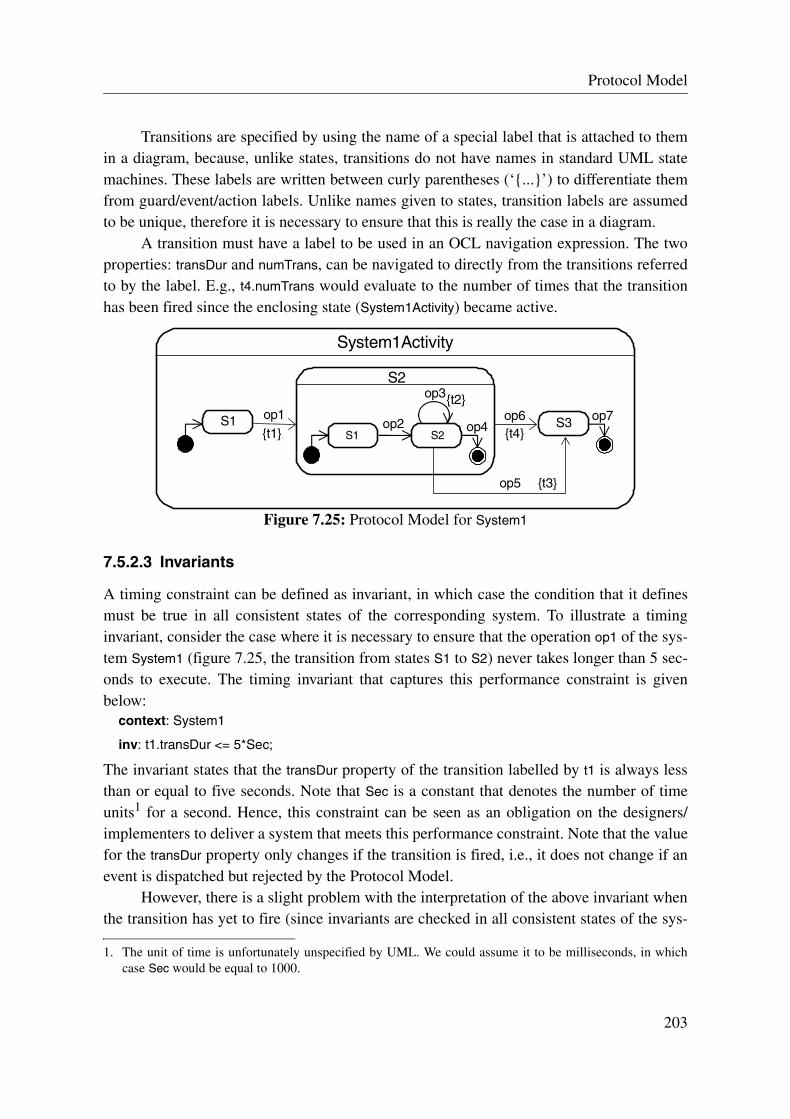
Protocol Model
Transitions are specified by using the name of a special label that is attached to themin a diagram, because, unlike states, transitions do not have names in standard UML statemachines. These labels are written between curly parentheses (‘{...}’) to differentiate themfrom guard/event/action labels. Unlike names given to states, transition labels are assumedto be unique, therefore it is necessary to ensure that this is really the case in a diagram.
A transition must have a label to be used in an OCL navigation expression. The twoproperties: transDur and numTrans, can be navigated to directly from the transitions referredto by the label. E.g., t4.numTrans would evaluate to the number of times that the transitionhas been fired since the enclosing state (System1Activity) became active.
Figure 7.25: Protocol Model for System1
7.5.2.3 Invariants
A timing constraint can be defined as invariant, in which case the condition that it definesmust be true in all consistent states of the corresponding system. To illustrate a timinginvariant, consider the case where it is necessary to ensure that the operation op1 of the sys-tem System1 (figure 7.25, the transition from states S1 to S2) never takes longer than 5 sec-onds to execute. The timing invariant that captures this performance constraint is givenbelow:
context: System1
inv: t1.transDur <= 5*Sec;
The invariant states that the transDur property of the transition labelled by t1 is always lessthan or equal to five seconds. Note that Sec is a constant that denotes the number of timeunits1 for a second. Hence, this constraint can be seen as an obligation on the designers/implementers to deliver a system that meets this performance constraint. Note that the valuefor the transDur property only changes if the transition is fired, i.e., it does not change if anevent is dispatched but rejected by the Protocol Model.
However, there is a slight problem with the interpretation of the above invariant whenthe transition has yet to fire (since invariants are checked in all consistent states of the sys-
1. The unit of time is unfortunately unspecified by UML. We could assume it to be milliseconds, in whichcase Sec would be equal to 1000.
S1 S2
S2
op2 op4 S3op6S1 op1
System1Activity
op5
op7
{t3}
{t4}{t1}
op3{t2}
203

Timing Constraints
tem), because the expression in the invariant will be undefined. Note that this is also a prob-lem for the use of the actTime property of states. OCL (and UML for that matter) does notstate what interpretation is given to an undefined invariant. Nevertheless, it is would seemunreasonable to assume that an undefined invariant is true (the desired interpretation in thiscase).
Note that initializing transDur and actTime to zero would not solve the problem either,because invariants that place minimum duration constraints would never hold initially. Forexample,
context: System1
inv: t1.transDur > 5*Sec;
Clearly, if the above invariant was evaluated with the expression t1.transDur equal to zerothen the invariant will not hold, which is not the desired interpretation.
To remedy this situation, I introduce a special (global) function called defined, whichis true whenever the expression is undefined, and equivalent to the truth of the expression,otherwise. Therefore, reworking the earlier invariant with the defined function, one gets thefollowing one:
context: System1
inv: defined (t1.transDur <= 5*Sec);
The invariant now asserts what was desired: every time the transition is fired its duration isalways less than or equal to five seconds.
It is important to note that in this example, the context is the system. I recommend thatthe context is always made to be a class of the system or the system, instead of makingstates or transitions the context. If states or transitions are the context of an invariant thenonly one property can be accessed, which would limit the specifier in the description of pos-sible timing invariants.
Using the system as the context, one can describe more sophisticated invariants. Forexample, assuming that the system System1 has an attribute numOfClients, which denotes thenumber of clients logged onto the system, one could define the following timing invariant:
context: System1 inv:
if self.numOfClients < 10 then
defined (t1.transDur <= 5*Sec)
elsif self.numOfClients < 100 then
defined (t1.transDur <= 10*Sec)
elsif self.numOfClients < 1000 then
defined (t1.transDur <= 50*Sec)
endif;
The above invariant asserts that if the numOfClients attribute of the system is under 10 thenthe transition labelled t1 must not take more than 5 seconds to complete, otherwise, if the
204
Protocol Model
attribute is under 100 (but clearly 10 or over), then t1 must not take more than 10 seconds tocomplete, otherwise, if the attribute is under 1000 (and 100 or over), then t1 must not takemore than 50 seconds to complete, otherwise there is no constraint on the duration of thetransition.
Consider another example of an invariant, which makes use of the propertiesnumTrans and actTime: it asserts that the first 9 transitions of the transition t2 are achievedbefore the encompassing state has been active for less than 1 second.
context: System1 inv:
defined (t2.numTrans < 10 implies System1Activity::S2.actTime < 1*Sec);
7.5.2.4 Guards
In addition to timing invariants, it is often necessary to state the circumstances in whichevents can not or should not be served because a certain time condition is not satisfied. Forthis purpose, guards on transitions with time conditions can be used. For example, onecould define a transition with a guard that rejects all firing of the transition t3 when thesource state has been active for more than 3 seconds. The following guard would beattached to transition t3:
[System1Activity::S2.actTime >= 3*Sec]
7.6 Protocol Model Example
To demonstrate the various concepts and notations introduced in this chapter, I present, inthis section, the Protocol Model for a Roulette system called VirtualRoulette. This system isused in a Casino like usual roulette tables, except that the game is managed and performedelectronically. Also, as an extension to the usual game of roulette, once bets have beenplaced, clients are allowed for a certain period to double their bets on the standing numbers(if they are feeling lucky).
VirtualRoulette allows clients to register with and log on to the system. Once logged onto the system, a client may join a roulette table and gamble. Each roulette game is per-formed by the system, but controlled by a single (human) game official. Each time the sys-tem determines that there is a certain number of players waiting to gamble, it opens a newtable. The system closes a table that has been idle for a certain period. A game official canonly be responsible for at most one table at any one time. Once a table is open for play, thegame is controlled by the game official. The game official follows a standard procedure forcompleting a round of roulette (call for bets, end bets, play round, and collect funds and payout winners). While a table is open, the game official can eject any gamblers that s/he dis-likes from the table. Figure 7.26 summarizes all the input messages of the system from thetwo actors: Client and GameOfficial. Note that there is a one-to-one name correspondence
205

Protocol Model Example
between these messages and the events placed on the input event queue of the system’s statemachine.
Figure 7.26: Overview of input messages for the system VirtualRoulette
In order to develop the Protocol Model for VirtualRoulette, I apply the divide-by-actor tech-nique to the client actor, first of all. Figure 7.27 shows the result. There are possibly manyclient activities (auto-concurrent state). Once registered, the client is a member and s/he canlog in and out of the system at will. Note that registration and logging in can fail: shown bythe self transition (guards are omitted). Once logged in, the client can gamble on up to threetables and can add funds to his/her gambling credit with the system (no withdraw is pro-vided, because it is assumed that the client is guaranteed to lose all his/her money).
Figure 7.27: Auto-concurrent client activity for VirtualRoulette
The Betting state is somewhat uninformative as to the protocol that the user has in joining atable, placing bets, doubling, and leaving the table. The reason for this lack of information isthat the betting protocol of the user is affected by the interactions that the game official ofthe respective table has with the system. To make the Betting state more informative, I intro-duce some synchronization transitions that take into account those events of the game offi-cial that relate to the user. Figure 7.28 shows the reworked betting state. It clarifies theprotocol that the client has with the system in performing bets. Also, note that the self tran-sition on the Idle state (with the joinTable transition) is shown to represent the fact that the
: Client
: VirtualRouletteregisterderegisterloginlogout addFundsjoinTableplaceBetdoubleleaveTable
: GameOfficial
ejectPlayercollectFundsAndPayOutcallForBetsendBetsplayRound
ClientActivity 0..*
register
register
login login
logout addFundsInactive
joinTableleaveTableplaceBiddouble
Betting 0..3
MemberActivity
deregister
Active
<<concurrent>>
206

Protocol Model
operation may fail to allow the user to join the table, e.g., the table already has the maxi-mum amount of participants. Note that two transitions with the same source state and eventplaceholder would require guards so that the target state may be determined. However, theguards have been omitted, according to the guideline stated in section 7.4.2.
Figure 7.28: Revised Betting State: adds synchronization with GameOfficial actor
I now apply the divide-by-actor technique to the game official actor. Figure 7.29 shows theresult. There are possibly many game official activities (auto-concurrent state). Once thegame official becomes responsible for a table, s/he goes through the procedure of runninggame rounds. Also, while the table is open, s/he can eject players. The two transitionsbetween the Idle state and the Active state are synchronization transitions that contain changeand time events. The change event (event denoted by the when keyword) is generated eachtime the condition timeToOpenTable becomes true, where the meaning is that it is time for thesystem to open another game table. The event is processed by the game official activity, ifthe event causes the system to open a table that the corresponding game official actor willreside at. The time event (event denoted by the after keyword) is generated after the tablehas been idle for 5 minutes. Again, the event is processed by the game official activity if theevent causes the system to close a table that the corresponding game official actor is resid-ing at. Both the actions for opening and closing a table are part of GameTableView, which isshown in figure 7.30.
Figure 7.29: Auto-concurrent game official activity for VirtualRoulette
To clarify the sequencing between the opening and closing of a table, and the protocolbetween the clients and the game official during a game round, the collaboration that centers
joinTablejoinTable
leaveTable
ejectPlayer/
Betting_V2 0..3
endBets/
callForBets/
placeBid double
BettingIdle InRound
endBets
GameOfficialActivity
playRound
collectFundsAndPayOut
callForBets
Active
ejectPlayer
Complete
Called
Closed
Closing
<<concurrent>>0..*
Idle
when (timeToOpenTable)/
after (5*Min) /
207

Protocol Model Example
around a game table is described using a view-state called GameTableView. The view-state isan auto-concurrent state and it is shown in figure 7.30. It highlights the collaborationbetween the clients and the game official, and it shows the transitions that relate to the open-ing and the closing of the corresponding table. For example, one could imagine that the con-dition timeToOpenTable becomes true when the system determines that there are a certainnumber of clients waiting to gamble.
Figure 7.30: Auto-concurrent game table view activity for VirtualRoulette
Bringing all these elements together, the Protocol Model for VirtualRoulette is shown infigure 7.31.
Figure 7.31: Protocol Model for VirtualRoulette
when (timeToOpenTable)/ openTable
after (5*Min)/ closeTable
TableOpen
endBets/
GameTableView
playRound/
collectFundsAndPayOut/
callForBets/
placeBid/ double/
TableClosed
Ready
Bids
Spinning
Changes
<<concurrent>> 0..*
<<concurrent>>VirtualRouletteActivity
<<concurrent>>GameOfficialActivity
0..*
<<concurrent>>GameTableView
0..*
<<concurrent>>ClientActivity
0..*
208

Chapter 8:
ANZAC Mapping Technique
This chapter presents the ANZAC mapping technique, which provides a systematic proce-dure for going from the ANZAC use case descriptions to the ANZAC specification for a sys-tem.
8.1 Introduction
The work of this thesis has focused on the development of an approach that can be used toprecisely and concisely communicate to the development team the required behavior of thefuture system. With respect to this objective, two distinct specifications were perceived tobe necessary. These specifications are referred to as the Behavioral Stakeholders Contractand the Behavioral Design Contract.
The Behavioral Design Contract is initially described by refining the BehavioralStakeholders Contract. Therefore, it is necessary to establish a means for refining the latterspecification to the former one. Such a refinement activity should also ensure that traceabil-ity between the two specifications is established, so that changes made to one can bemethodically propagated to the other one.
In this chapter, I present the ANZAC mapping technique, which provides a systematicprocedure for refining ANZAC use case descriptions to an ANZAC specification. TheANZAC mapping technique involves message identification from use case descriptions,collecting system responsibilities, defining the system’s input protocol with its environ-ment, formalizing the system’s responsibilities, and performing checks on the resultingANZAC specification.
209
Relating the ANZAC Use Case Descriptions to the ANZAC Specification
In section 8.2, I describe the characteristics of ANZAC use case descriptions and theANZAC specification that facilitate the mapping between them. In section 8.3, I describethe ANZAC mapping technique in a step-by-step manner. Note that I defer illustrating theANZAC mapping technique on an example until the next chapter (Chapter 9).
8.2 Relating the ANZAC Use Case Descriptions to the ANZAC Specification
In this section, I describe the similarities of ANZAC use case descriptions and the ANZACspecification. Also, I discuss some of the benefits of mapping ANZAC use case descriptionsto an ANZAC specification.
8.2.1 Noteworthy Characteristics of ANZAC Use Case Descriptions
An ANZAC use case description provides a plan of the possible interactions between thesystem and the actors in its environment in the form of a set of scenarios. These interactionsform an informal statement of the system’s interface to its environment and the responsibil-ities that it has in reacting to requests and notifications made by actors. ANZAC use casedescriptions state the system’s responsibilities without mentioning any of the internal detailsof how the software fulfills these responsibilities, i.e., they are black-box descriptions.
8.2.2 Noteworthy Characteristics of an ANZAC Specification
An ANZAC specification describes a system by offering three distinct but complementaryviews of it. The three views are described by the Concept Model, the Operation Model andthe Protocol Model. The Concept Model describes the (abstract) state space of the system.The Operation Model states the responsibilities and assumptions that the system has in per-forming each operation. The Protocol Model specifies which operations are performed bythe system in reaction to stimuli received over time. An ANZAC specification is a black-box description, where the internal details of the system in focus are left unmentioned.
8.2.3 Relating the Use Case Descriptions to Each Model of the ANZAC Specification
ANZAC use case descriptions provide an informal description of each responsibility that isplaced on the system from interactions with its environment. These responsibilities can thenbe grouped together to form the description of each system operation. These descriptionscan then become a basis for refinement into the Operation Model of the ANZAC specifica-tion.
210

ANZAC Mapping Technique
ANZAC use case descriptions provide a good starting point for defining the ProtocolModel of the ANZAC specification, because the set of scenarios described by each use casedescription provides a basis for specifying the temporal ordering of operations and forestablishing the system’s activities.
It is important to mention that the initial construction of the Concept Model is not per-formed by refinement from the ANZAC use cases. Rather, a Concept Model is initiallyderived from a domain model, which describes the concepts of the application domain. This“first-cut” of the Concept Model is refined with the development of the Operation Model,where the Concept Model is kept up-to-date with all the modifications that are necessary tokeep synchronized with the Operation Model.
8.2.4 Benefits of Relating ANZAC Use Case Descriptions to an ANZAC Specification
The benefits of refining the use case descriptions into an ANZAC specification are the fol-lowing:
• If care is taken in the refinement activity, then the responsibilities of the system thatare described by an ANZAC specification can be traced to high-level goals of stake-holders. In such cases, the ANZAC specification can be justified against the goals andinterests of the stakeholders. This justification allows the stakeholders greater confi-dence that the system under design is in fact appropriate.
• In the reverse direction, if a high-level goal of a stakeholder can be refined into a setof realistic system responsibilities and interactions with its environment, then the goalis confirmed to be viable, which is a form of goal validation.
• The refinement activity promotes iteration, because it forces specifiers to review andremove some of the ambiguities and imprecisions of the ANZAC use case descrip-tions, leading to use cases that have a more consistent level of detail and precision.
• The refinement activity drives the specifiers to describe more concretely the concur-rent behavior of the system and the timing constraints that are needed.
• The refinement activity allows specifiers to formalize and prioritize developmentincrements. This information can then be distributed among the development team,providing a guide for parallel development.
• The refinement activity offers the opportunity to define traceability links betweenANZAC use case descriptions and an ANZAC specification. This means that changesto one of them can be propagated to the other one in a systematic manner.
211

ANZAC Mapping Technique
8.3 ANZAC Mapping Technique
In this section, I present the ANZAC mapping technique. It is explained as a series of stepstaking one from a set of ANZAC descriptions to an ANZAC specification. However, it isimportant to note that the process for applying the ANZAC mapping technique may be non-linear, i.e., steps may be repeated, steps may be performed out of order, etc.
A Note on IncrementsIf an incremental development process is applied to the ANZAC approach, then theANZAC mapping technique would be applied to only a subset of the ANZAC use casedescriptions for the system. In such cases, the use cases descriptions that are treated as inputfor the mapping should include at least some user-goal and sub-function goal level use casedescriptions. Otherwise, the validation obtained from stakeholders with respect to the sys-tem operations would be questionable1 and most of the work would be still left to do in thedevelopment of the ANZAC specification.
A general rule of thumb for finding a sufficient set of use cases is to ensure that thelowest goal level of the ANZAC use case descriptions have a granularity of step that issmaller than a single application-logic interaction between an actor and the system. (Notethat the stress is on application-logic level, as opposed to presentation-logic level, in thecase that the actor is a human, for example.)
8.3.1 ANZAC Mapping Technique Step by Step
It is assumed in the following description of the ANZAC mapping technique that the termsand concepts discussed in the chapters describing each of the models of an ANZAC specifi-cation are familiar to readers.
Step 1: From the ANZAC use case descriptions, identify incoming and outgoingmessages and internal triggers, and rationalize the choices made
The aim of this step is to define all incoming and outgoing messages (relative to the system)and internal triggers from analyzing the use case descriptions. Step 1 consists of three sub-steps.
Step 1.1 Identify Messages and Internal Triggers
For each use case that is a leaf2 in the use case hierarchy (tree) for the system, the steps ofits main success scenario and extensions clauses are analyzed for the following three ele-ments:
1. The ANZAC specification is less easily justified if the link between the operations and the stakeholdergoals is vague or superficial.
2. Only “leaf” use cases (in the goal hierarchy) are considered, because they provide the most detailed viewof the interactions between the system and actors.
212

ANZAC Mapping Technique
• Input messages – they are derived from steps that describe an actor making a requestor communicating a notification to the system.
• Output messages – they are derived from steps that describe the system makingrequests or communicating notifications to one or more actors.
• Internal triggers – they are derived from steps that describe system-instigated actions.
For each system-instigated action candidate found, an internal trigger definition is created,which includes a description of the trigger-condition written in OCL or natural language.For each message candidate found, a message definition is created, where the message’sname matches the intention of the request or notification, and its parameters represent thenecessary information to communicate to its target. All parameter types must be part of theConcept Model.
In general, input and output messages should not be difficult to find if the use case hasbeen defined at an appropriate level of detail. Input and output messages that have a userinterface flavor should be avoided, i.e., messages should represent application-logic levelrequests and notifications.
Internal triggers are often more difficult to extract from use cases. In general, they aremost easily found after all input messages have been accounted for. At this moment, the usecase can be checked to see that all system actions have corresponding messages that triggerthem. If a “message-less” action is found, either a message has been missed (and a new oneshould be defined), or the action is system-instigated and therefore the condition that trig-gers the action should be defined.
Step 1.2 Rationalize Messages and Internal Triggers
Once all input and output messages and internal triggers have been found, each one shouldbe rationalized as a distinct element with respect to the others, where the three groups aredealt with separately. This means that elements that are judged to be similar or the same areunified into a single element. Furthermore, for certain kinds of systems, there may be alarge number of output messages, of which a large percentage of these are error messages(exceptions). In such cases, it may be worthwhile to group related messages and differenti-ate them by parameterization to reduce the clutter and enhance the clarity of the description.
Step 1.3 Annotate Use Case Description with Messages and Internal Triggers
For each use case that is analyzed, each step of the use case is annotated with all messagesand internal triggers that are judged to be related to that step. Note that this does not meanthat messages/internal triggers are only placed on those steps that led to the uncovering ofthe message/internal trigger, but rather that they are added to each and every step that “use”them. The annotation has the following (EBNF) form:
Annotation ::= “[” Body+ “]”Body ::= “in” “->” InputMessageName (“,” InputMessageName)* “;”
| “out” “->” OutputMessageName (“,” OutputMessageName)* “;”| “cond” “->” TriggerCondition (“,” TriggerCondition)* “;”
213

ANZAC Mapping Technique Step by Step
For example, by analyzing the following step (from a use case for a Red Bull vending sys-tem), a RequestRedBull message is identified as incoming.
1. User requests System for a Red Bull
The resulting annotation to the use case step, with the RequestRedBull message, is the fol-lowing one:
1. User requests System for a Red Bull [in -> RequestRedBull]
Result of Step 1
The result of this first step in the ANZAC mapping technique is a set of annotated use casedescriptions, and message and internal trigger definitions. In addition to these ones, it canbe useful to provide an overview of all messages exchanged between the system and itsactors (i.e., those messages found after applying this step) with a specification-level UMLcollaboration diagram, which is shown without sequence numbers (ordering is dealt with instep 3).
Step 2: Collect system responsibilities related to each input message andinternal trigger
The aim of this step is to provide a rough overview of the responsibilities that are placed onthe system with respect to the reception of input messages or internal triggers (found byapplying step 1).
For each input message, all steps of (annotated) use cases that indicate any actionsperformed by the system in response to this message are collected and related to the mes-sage definition as an informal comment. Rather than repeating the description given in theuse case, the comment simply cross-references the steps of use cases that describe the corre-sponding responsibilities, i.e., all system responsibilities that are caused by this message.These cross-references support traceability between the use case descriptions and theANZAC specification. Note that the actions that relate to a particular message are often partof different use case steps to those ones that include the message as an annotation, i.e., the“cause” may be found in a different part of the use case to the “effect”. Therefore, the activ-ity of collecting the responsibilities of the system is more complicated than just collectingall steps that have the message as an annotation.
Similarly, for each internal trigger, the step of the use case that describes the relatedsystem-instigated action is related to the internal trigger definition as an informal comment(in the form of a cross-reference to the use case step). Note that usually an internal triggerhas only one related use case step.
Result of step 2
The result of this second step in the ANZAC mapping technique is a set of annotated inputmessage and internal trigger definitions.
214
ANZAC Mapping Technique
Step 3: Define the system’s input protocol with its actors and establish operationsignatures and responsibilities
The aim of this step is to define the Protocol Model for the system using the set of annotatedinput message and internal trigger definitions, which are found by applying step 2, and toestablish the informal responsibilities of operations. Step 3 consists of five sub-steps.
Step 3.1 Map Input Messages and Internal Triggers to Events
All input messages and internal triggers are mapped to events. Each (input) message ismapped to a signal or call event with the same signature (i.e., same name and parameterlist). Also, each internal trigger is mapped to a time or change event. Thus, each event corre-sponds to the reception of a message sent by an actor to the system or of an internal triggergenerated by the system.
Input messages are mapped to signal events by default. However, if there is a specificneed or requirement for synchronous communication, then the corresponding message ismapped to a call event. An internal trigger is mapped to a time event if its trigger-conditiondenotes a deadline expiration, otherwise it is mapped to a change event, where the trigger-condition becomes the condition associated to the change event.
Step 3.2 Apply Divide-By-Actor Technique
Once all events have been defined, the divide-by-actor technique is applied to the system.This technique is used to describe the input protocol between the system and each actor typeas a separate activity. Each activity is described by a composite state, which is referred to asan actor-activity-state. By default, the divide-by-actor technique follows the inherent con-currency guideline, i.e., if there are no explicit concurrency requirements. This guideline isderived from the fact that each actor instance is a concurrent source of stimuli that can inter-act with the system independently of all other actor instances. The guideline states that theinteraction that an actor has with the system may take place concurrently to the interactionsthat other actors have with the system, but a single actor (instance) can not interact with thesystem in parallel (in general).
For each actor, an actor-activity-state expresses the actor’s (acceptable) input protocolwith the system in terms of the temporal constraints on the ordering of events. And itdefines the system’s reaction to these events in all circumstances. The transitions in anactor-activity-state, which define the ordering constraints, include an event placeholder andan operation (the action that is triggered on firing of the transition).
An operation signature is defined for each transition. The name of the operationshould always represent the effect of the responsibilities that it encapsulates1. Note that anoperation that is associated to an event may only encapsulate some of the responsibilitiesthat were found for the corresponding message in step 2. In such cases, the complete set of
1. Page-Jones provides a good discussion on how responsibilities should be distributed among operations andhow operations should be appropriately named [P-J99].
215

ANZAC Mapping Technique Step by Step
responsibilities are split across multiple operations, where the decision of which operationto execute is based on the current state of the system.
The responsibilities of the operations are informally noted by cross-referencing thecorresponding use case steps. In the case that the cross-reference to the use case step is notsufficiently explicit, the responsibilities of the operations may be reformulated in an infor-mal description in addition. In formal development settings, it may be worthwhile to use anOperation Schema by directly filling in the Operation, Description and Use Cases clauseswith this information.
If the protocol between the system and an actor is tightly coupled to the interaction ofother actors with the system, then synchronization transitions can be added to enhance thedescription of the protocol for the actor. Note that synchronization transitions are operation-less, i.e., they only contain event placeholders.
Step 3.3 Apply Divide-By-Collaboration Technique
Once the actor-activity-states have been established, the divide-by-collaboration techniqueis applied to the system. This technique is used to describe the input protocol between thesystem and the actors for each meaningful collaboration. Each collaboration is described bya composite state, which is referred to as a view-state. This technique can be particularlyuseful for capturing different aspects of the concurrent behavior of the system.
Before tackling the description of a particular collaboration, it is often desirable toconstruct view-states for those use cases that describe a certain aspect of the collaboration.These view-states can then be composed to form a description of the complete collabora-tion. Also, some view-states that are described using the divide-by-collaboration techniquemay be used as alternatives to actor-activity-states. In particular, a view-state is allowed toreplace a set of actor-activity-states if it observes the concurrent nature of the system and itincludes all operations mentioned in the actor-activity-states.
All events and operations that relate to internal triggers are described by view-states.The trigger-conditions of the internal trigger definitions are used to define when change andtime events are generated. Moreover, operations are attached to time or change event transi-tions like for the other kinds of events. The responsibilities of the operation correspond tothose ones described in the internal trigger definition.
As the protocol for each collaboration is progressively described using the divide-by-collaboration technique, the operations that are associated to transitions are given signa-tures. Similarly to the divide-by-actor technique, the responsibilities of the operations arenoted by cross-references to the corresponding use case steps.
Step 3.4 Ensure Consistency between Actor-Activity-States and View-States
The Protocol Model for the system is defined by the combination of all actor-activity-statesand view-states that result from the application of the divide-by-actor and divide-by-collab-oration techniques. Care needs to be taken that the concurrent behavior defined by the
216

ANZAC Mapping Technique
resulting Protocol Model matches the intended one, and that at most one operation is trig-gered by an event occurrence.
Step 3.5 Add Timing Constraints
Once the Protocol Model is established, timing constraints are added. Timing constraintsare derived from requirements that relate to response time, waiting time, arrival rate, thenumber of events processed in some interval of time, etc. Timing constraints will either leadto additional system invariants, the addition of guards on transitions, or additional time orchange events, which trigger operations that respond to passed deadlines.
Timing requirements are informally mentioned in the “Timing Requirements” clauseof an ANZAC use case description. Guidelines for specifying timing constraints on the Pro-tocol Model can be found in Chapter 7.
Result of Step 3
The result of this third step in the ANZAC mapping technique is the Protocol Model for thesystem and a set of informal operation descriptions.
Step 4: Formalize the system’s responsibilities by an Operation Model
The aim of this step is to define the Operation Model using the set of informal operationdescriptions, which are found by applying step 3. Step 4 consists of two sub-steps.
Prerequisite of Step 4
A prerequisite for this step is that the Concept Model for the system is in a form that can beused as the reference for types in Operation Schemas. Note that the Concept Model willalmost always undergo changes as each operation is described by an Operation Schema, i.e.,new entities/relations will be added and others removed to take into account what is neededin the descriptions of operation effects.
The “All at Once” Approach and the “Atomic/Non-Atomic Split” Approach
The sub-steps given below take the approach of defining directly the synchronization con-straints in the Operation Schemas for concurrent operations; I refer to this approach as the“all at once” approach. However, an equally viable approach is to first develop the Opera-tion Schemas as though they are executed atomically (instantaneous-operation assumption)and then refine them to descriptions of truly concurrent operations; I refer to this approachas the “atomic/non-atomic split” approach. The advantage of the second approach is that thecomplexity of developing Operation Schemas is reduced, because you first concentrate ondescribing the functionality, and only after you have captured the functionality do you goabout introducing synchronization information.
The “all at once” approach proposed below can be seen as the preferred approach foradvanced specifiers, and the “atomic/non-atomic split” approach can be seen as the pre-ferred approach for specifiers that are not so familiar with the techniques for describing con-current operations, given in Chapter 6.
217

ANZAC Mapping Technique Step by Step
Step 4.1 Basic Structure of Operation Schema
The operation signatures and the references to their responsibilities (in the use cases),obtained in step 3, are used as the basis for constructing an Operation Schema for each oper-ation. Given this information, the Operation and Use Cases clauses can be directly filled in.In consulting the referenced use case steps, the Description and Messages clauses usuallyfollow in a straight-forward manner.
If the Protocol Model for the system contains concurrent states, then the sharedresources for operations will need to be found. Note that if the Scope clauses of all theOperation Schemas are defined then the shared-clause algorithm (Chapter 6) can be used tocalculate the Shared clause for each Operation Schema. If shared resources are found, thenthe Operation Schema should be described using the techniques described in Chapter 6 forconcurrent operations.
Step 4.2 Describe the Pre- and Postcondition Assertions
The Pre clause is developed by reflecting on what assumptions are made about the parame-ters of the operation and state of the system before the operation’s execution. These assump-tions are described in terms of assertions.
The Post clause is developed by consulting the relevant use cases (referenced by theUse Cases clause) and the Concept Model. The corresponding steps in the use cases provideinformation about the operation’s responsibilities. These responsibilities need to be trans-formed into assertions about the effect of the operation on the state of the system and themessages that are output with the operation’s execution. All assertions are made on entitiesand relations that specified by the Concept Model, or about messages that are declared inthe Messages clause.
Result of Step 4
The result of this fourth step in the ANZAC mapping technique is an established OperationModel and Concept Model.
Step 5: Perform checks on the resulting ANZAC specification
The aim of this step is to check the resulting ANZAC specification for correctness, consis-tency and completeness, and to ensure that it has been correctly refined from the ANZACuse case descriptions. Each model of the ANZAC specification should be correct in terms ofits syntax and type usage; consistent with respect to itself, the other models, and the usecase descriptions; and complete with respect to the other models and the use case descrip-tions.
In addition to standard syntax and type checks (which are covered by the respectivechapters of the three models), the following checks should be performed to each model:
• Operation Model: - The output messages that are declared in the Messages clause of each Operation
Schema match those identified in step 1 of the mapping technique.
218

ANZAC Mapping Technique
- All classes, attributes and associations that are used by the Operation Schemas aredefined in the Concept Model.
- The Use Cases clause of each Operation Schema references actual steps of usecases.
- All Parameterized Predicates and Functions used in the Operation Schemas aredefined.
- The Operation clause of each Operation Schema declares parameters that are men-tioned in the signature of the triggering event(s).
- The resources that are mentioned in the Shared clause of each Operation Schemaare shared with operations that may execute concurrently to the respective opera-tion (according to the Protocol Model).
• Protocol Model:- Each input message and internal trigger (found by applying step 1) has one corre-
sponding event type, and this event is associated to one or more transitions in theProtocol Model.
- No events other than those ones that have been defined in step 3 are mentioned inthe Protocol Model.
- All operations shown in the Protocol Model are described by Operation Schemas.
• Concept Model:- The Concept Model does not include any concepts that are not mentioned in the
Operation Model1.- All invariants defined by the Concept Model (which includes multiplicities) are not
contradicted by the Pre and Post clauses of the Operation Schemas.
As a general check, the traceability between the Operation and Protocol Model and theANZAC use case descriptions should be examined. In particular, it should be ensured thatthe system’s responsibilities, which are described by steps of use case descriptions, are cor-rectly represented by the Operation Schemas. Also, the ordering of messages implied by theuse cases should be correctly described by the Protocol Model.
1. This is an important check, because the Concept Model should strictly only describe the state space of thesystem, and not just any concept that is related to the system.
219

ANZAC Mapping Technique Step by Step
220
Chapter 9:
Elevator Case Study
This chapter applies the ANZAC approach to an elevator control system. It takes the readerprogressively through the development of the system using the ANZAC approach, offering afull treatment of it. In particular, it presents the ANZAC use case descriptions and theANZAC specification for the elevator control system, and it illustrates the steps taken tomap the first to the second one using the ANZAC mapping technique. The concurrent behav-ior and timing requirements of the elevator control system are also addressed.
9.1 Introduction
The elevator control case study is concerned with the development of an embedded systemfor controlling the movement of a single elevator cabin and the opening of the cabin’s door.The system, which I refer to as ElevatorControl, bases its decisions for controlling the cabinand door on the requests made by the users of the elevator and information it receives fromthe door, sensors and motor controllers. Apart from offering a reasonably complete illustra-tion of the ANZAC approach, this case study offers a different challenge to some of theexamples given in previous chapters, because ElevatorControl communicates with controllersthat have predefined interaction protocols.
9.1.1 Problem Statement for the ElevatorControl system
The ElevatorControl system is responsible for controlling an elevator cabin for the purpose ofserving requests made by elevator users. A user requests for the cabin at a particular floor(pick up) or s/he requests the cabin to go to a particular floor (drop off); they are referred to
221

ANZAC Use Case Descriptions
as external requests and internal requests, respectively. The system does not treat userrequests directly but rather receives them via a request intermediary, i.e., the request inter-mediary communicates to the system the requests that originate from floor and cabin but-tons. There is one request intermediary for all internal requests and one for all externalrequests (i.e., two in all). Furthermore, requests are direction-less (in the case of externalrequests), they are definitive, i.e., they cannot be cancelled, and they should eventually beserved. Also, once a request has been served, the system should inform the appropriaterequest intermediary of this fact.
The system may ask the cabin door to open. The cabin door1 is responsible for closingitself and it informs the system when it has just closed. This means that the system is notresponsible for telling the door to close. In the case that the door is already open and it istold to reopen, the door will continue to stay open for a new time period. The door is guar-anteed to stay open for at least 5 seconds.
The arrival of the cabin at a floor is detected by a sensor (there is a sensor for eachfloor). On detection of the cabin, the sensor informs the system of this situation. It takes atleast 1.5 seconds and at most 2 seconds to go from one floor to another one, i.e., the timebetween sensor events. The system may ask the cabin motor to go up, go down or stop. Themotor will stop the cabin correctly at the approaching floor, given sufficient notice. Thus, allcomplexities involved in calculating how to stop (deaccelerations, etc.) is dealt with by themotor and is not a responsibility of the system. Once the motor has stopped the cabin, itinforms the system that it is stopped.
In stopping the cabin, the system must give the motor sufficient time to stop the cabin.In terms of timing requirements, “sufficient time” means that the system must decide within0.1 seconds if it is to stop the cabin.
9.2 ANZAC Use Case Descriptions
In this section, I develop the ANZAC use case descriptions for the ElevatorControl system byapplying the ANZAC approach and given the problem statement.
For size reasons, I do not discuss the approach taken to develop the use cases: I justconcentrate on describing the results. Also, I consider only a single user-goal level use casefor the ElevatorControl system (which is refined into two sub-functional level use cases): thegoal of a User actor to take the cabin from one floor to another, which is called Take Elevator.This use case is shown in figure 9.1. The use case’s primary actor is User and its secondaryactors are not visible at this level of description.
1. Only one door is mentioned because logically an elevator can be seen as having a single door consisting oftwo parts (i.e., the cabin door and the floor door) that are always synchronized.
222

Elevator Case Study
Figure 9.1: Take Elevator use case for ElevatorControl system
The Take Elevator use case has two steps in its main scenario, which are both sub-use cases1,and it has a single extension step, which is taken on the failure of a performance of the Enter
Cabin (sub-) use case. The Take Elevator use case provides the context of the users that aretaking the elevator (Intention in Context clause), which is useful to know when decidingwhich scheduling policy might be appropriate, for example. Also, note that no secondaryactors appear at this (quite abstract) level of description.
Enter Cabin use caseThe Enter Cabin use case captures the goal of the user to enter the elevator cabin at therequested floor. Note that this is a sub-goal of the user’s goal to take the elevator from onefloor to another. However, no mention of this fact is made in the Take Elevator use case so asto promote reuse. Thus, each level in the use case hierarchy is isolated from the upper level.The Enter Cabin use case has six main scenario steps. The third and fourth steps are related:the system is informed about the floors that the cabin is arriving at (step 3); using this infor-mation, the system can determine that the cabin has reached the source floor of the request(the one where the user is waiting), leading to the system stopping the cabin at that floor(step 4). Note that this use case defines some timing requirements, which are taken verbatimfrom the problem statement and associated with the appropriate steps. Also, note that theMotor, Door and Sensor secondary actors are now visible. However, the intermediary role ofthe ExtReqSource is still unmentioned by the use case.
1. The underlined text in these two steps signifies a hyperlink to the corresponding descriptions of the sub-use cases (symbolic in this case).
Use Case: Take ElevatorSystem: ElevatorControlLevel: User-GoalIntention in Context: The User intents to go from one floor to another using the elevator. TheSystem has a single cabin that may service many users at any one time. The Users arepredominantly office workers that are taking the elevator for the purpose of: going to and comingfrom work.Primary Actor: UserMain Success Scenario:1. User enters cabin2. User exits cabin at destination floorExtensions:1a. User fails to enter cabin; use case ends in failureOther Concurrent Use Cases:This use case can perform concurrently to possibly many other “Take Elevator” use cases.
223

ANZAC Use Case Descriptions
Figure 9.2: Enter Cabin use case for ElevatorControl system
The Enter Cabin use case has three extension steps. The first two extension steps are alterna-tives to step 2. The first extension step (2a) is taken if the system is already busy withanother request. In this case, the system schedules the request for later. This extension steprejoins the main scenario at step 2, which indicates that the request will eventually be servedby the system. The second extension step (2b) is taken if the request made by the user is forthe same floor as the one where the cabin is stationed. In this case, the use case joins themain scenario where the system asks the door to open. The third extension step (2-6 a) is analternative to any step between 2 and 6 inclusive. The step is used to show the scenariowhen the user simply walks away. Although this step is not directly detectable by the sys-tem, it is worth mentioning because it is a fact of the environment that may at some point berelevant to the system. For example, this point may deter any decisions that would force thecabin to wait for the user’s internal request (after the external request has been serviced).
Exit Cabin use caseThe Exit Cabin use case captures the goal of the user to exit the cabin at his/her destinationfloor, which is a sub-goal of taking the elevator from one floor to another (Take Elevator usecase). The Exit Cabin use case has seven main scenario steps1. The first two can be per-
Use Case: Enter CabinSystem: ElevatorControlLevel: Sub-FunctionIntention in Context: The User intents to enter the elevator cabin at a certain floor.Primary Actor: UserMain Success Scenario:1. User makes a request to System for cabin2. System requests Motor to move towards source floor; Motor goes in direction of source floorStep 3 is repeated until System determines that the source floor of the User has been reached3. Sensor informs System that cabin has reached a certain floor4. System requests Motor to stop cabin; Motor stops cabin and informs System that it is stopped;5. System requests Door to open, and informs User that request has been fulfilled; Door opens6. User enters cabin at source floorExtensions:2a. System is serving another request:
2a.1. System schedules the request; use case continues at step 2 (when System decides toserve this request).
2b. System determines that cabin is already at requested floor; use case continues at step 51.(2-6)a. User walks away2; use case ends in failureTiming Requirements:Step 3: “It takes at least 1.5 seconds and at most 2 seconds to go from one floor to another one”.Step 4: “the system must decide within 0.1 seconds if it is to stop the cabin”.Notes:1 It is possible that the door may already be open (assumption: requesting door to open while it isalready open will make it stay open for a new time period).2 This is not detectable by the System. The only way the System could determine that the userhas left is if it times-out on waiting for a request.
224

Elevator Case Study
formed in any order, because the door may close before or after the user makes a request.Steps 3-6 are similar to those found in the Enter Cabin use case (steps 2-5). Note that this usecase does not cover the case when a user does not make a request. In this case, the user canbe seen as a passive rider, who is taken “on the back” of another user who makes therequest. This case is not deemed sufficiently noteworthy to mention in the use case. Also,this use case defines some timing requirements, which are taken verbatim from the problemstatement and associated with the appropriate steps. Note that there is some overlap withthose defined for the Enter Cabin use case.
The Exit Cabin use case has five extension steps. The first one (2a) is an alternative tostep 2. It is taken if the request made by the user is the same floor as the one where the cabinis currently stationed. The second extension step (2-6 ||a) takes place if the user makes anadditional request to the system in parallel to steps 2, 3, 4, 5 or 6. In this case, the systemschedules the request and continues the main scenario normally. The third extension step(3a) is an alternative to step 3. It is taken if the system decides that another request has pri-ority and it serves that one first (i.e., it does not serve the user’s request straightaway). Inthis case, the system schedules the request for later. This extension step rejoins the mainscenario at step 3. The fourth extension step (3b) is taken if the system is already busy withanother request (e.g., the user was too slow in making a request). In this case, the systemschedules the request for later. This extension step rejoins the main scenario at step 3, wherethe request will eventually be served by the system, according to the main scenario. Thefifth extension step (7a) is an alternative to step 7. It is taken if the user previously chose togo to another (additional) destination. In this case, the use case continues at step 2.
As highlighted by the third note in the Notes clause of the Exit Cabin use case, the sys-tem can not know which requests are made by which User actors. This point is worth men-tioning, however, because it may make the stakeholders reconsider their requirements, e.g.,should a user be allowed to cancel requests, would it be interesting to have “personalized”requests for VIP riders, etc.
1. Note that it would have been possible to group these steps into three sub-goals of the user: user makesrequest, user waits for floor and user leaves cabin, and describe use cases for each one. This approach hasnot been taken for space reasons, and because it is not always profitable to have too many small use cases.
225

ANZAC Specification
Figure 9.3: Exit Cabin use case for ElevatorControl system
9.3 ANZAC Specification
In this section, I describe the ANZAC specification for the ElevatorControl system. Insection 9.3.1, I present the Concept Model for the ElevatorControl system. From thereon, Idescribe the steps taken to derive and refine the ANZAC specification from the ANZAC usecase descriptions for the ElevatorControl system. These steps follow the ANZAC mappingtechnique described in Chapter 8.
Use Case: Exit CabinSystem: ElevatorControlLevel: Sub-FunctionIntention in Context: The User intents to leave the elevator cabin at a certain floor.Primary Actor: UserMain Success Scenario:Steps 1 and 2 can happen in any order1. User makes a request to System to go to a floor2. Door times-out on open period and closes itself, and informs System that it is closed3. System requests Motor to move towards destination floor; Motor goes in direction ofdestination floorStep 4 is repeated until System determines that the destination floor of the User has been reached4. Sensor informs System that cabin has reached a certain floor5. System requests Motor to stop cabin; Motor stops cabin and informs System that it is stopped;6. System requests Door to open, and informs User that request has been fulfilled; Door opens7. User exits cabin at destination floorExtensions:2a. System determines that cabin is already at requested floor; use case continues at step 61.(2-6)||a. User requests System to go to a different floor2:
(2-6)||a.1. System schedules the request; use case joins main scenario.3a. System decides to serve another request:
3a.1. System schedules the request; use case continues at step 3 (when System decides toserve this request).
3b. System is serving another request (step 2 occurred before step 1):3b.1. System schedules the request; use case continues at step 3 (when System decides toserve this request).
7a. User has additional requests pending3: use case continues at step 2.Timing Requirements:Step 4: “It takes at least 1.5 seconds and at most 2 seconds to go from one floor to another one”.Step 5: “the system must decide within 0.1 seconds if it is to stop the cabin”.Step 6: “The door is guaranteed to stay open for at least 5 seconds”.Notes:1 It is possible that the door may already be open (assumption: requesting door to open while it isalready open will make it stay open for a new time period).2 There is no canceling of requests.3 System cannot make a difference between a single user making many requests and manyusers each making a request.
226

Elevator Case Study
9.3.1 Concept Model
In this subsection, I describe the Concept Model for the ElevatorControl system. Note that theinitial construction of the Concept Model is not part of the ANZAC mapping technique,because the Concept Model is not directly derived from the ANZAC use case descriptions.Instead, an initial Concept Model is usually derived from a description of the concepts ofthe application domain1. Note that in this thesis I do not address this aspect. An example ofa domain model that was used to derive a “first-cut” of the Concept Model for the Elevator-
Control system can be found in [Se02b].As part of the mapping activity, the “first-cut” of the Concept Model is refined and
changed as the Operation Model is developed. Entities and relations, which represent con-cepts of the problem domain, are introduced on a “need to know” basis, which means thateach entity/relation must be justified from the perspective that it allows the system to retainthe essential information that it needs to meet its responsibilities. Hence, the Concept Modelis tightly coupled to the Operation Model. In fact, the Concept Model can not be consideredstable until all functionality (of the increment) has been investigated with the OperationModel.
The Concept Model that I present in this subsection shows the synthesis of all themodifications made during the development of the Operation Model (section 9.3.5). There-fore it can be seen as a result of step 4 of the ANZAC mapping technique applied to the Ele-
vatorControl system. I show it as a precursor to the application of the ANZAC mappingtechnique, however, because it is used in the explanation of the Protocol and OperationModels.
The Concept Model for the ElevatorControl system is shown in figure 9.4. It defines the(abstract) state space of the ElevatorControl system in the form of classes, associationsbetween these classes, constraints on the possible number of instances of classes and associ-ations, and other invariants. Inside the system, there are three (normal) classes, Cabin, Floor,and Request, and five <<rep>> classes, Motor, Door, ReqSource, IntReqSource, ExtReqSource.ReqSource is an abstract class, and Cabin, Motor, Door, IntReqSource and ExtReqSource haveonly a single object in the system (which matches the fact that the system only interactswith a single instance of these actors). Cabin has two attributes: movement, which indicateswhether the cabin is going up, down, stopping, or stopped; and doorState, which indicateswhether the cabin door is open or closed. Floor has a single (frozen) attribute called num,which indicates the level in the building within which it is contained2.
The system has five (non-composition) associations: IsFoundAt links a cabin to its cur-rent floor; HasCurrentRequest links the cabin to the current request that it is serving, if thereis one; HasTargetFloor links request objects to their (frozen) target floor (source or destina-
1. Such a description of the domain is also important to set a common vocabulary across the project.2. Note that for convenience, integer was chosen as the type of num. However, this may need to be made
more general to cover more “exotic” numbering schemes.
227

Concept Model
tion); and HasSource links a request object to the (frozen) actor rep object that represents theactor that made the request. The system has two invariants: noMovingWithDoorOpen, which states that if the cabin door isopen then the lift must be stopped and if the cabin is moving then the door is closed; andstrictlyIncreasingFloorNumbers, which states that for each floor there is exactly one floorabove it and one floor below it, unless it is the top or bottom floor, respectively. These twoinvariants, written in OCL, are shown below.
context Cabin inv noMovingWithDoorOpen:self.doorState = DoorState::opened implies self.movement = Movement::stopped &self.movement <> Movement::stopped implies self.doorState = DoorState::closed;
context ElevatorControl inv strictlyIncreasingFloorNumbers:self.floor->forall (f1 | -- for each floor in the system
(self.floor->one (f2 | f2.num = f1.num + 1) or self.floor.num->max () = f1.num)-- there exists exactly one floor higher than it or it is the top floor
and (self.floor->one (f2 | f2.num = f1.num - 1) or self.floor.num->min () = f1.num)-- and there exists exactly one floor lower than it or it is the bottom floor
) &self.floor->forall (x, y | x.num = y.num implies x = y); -- all numbers are unique
Figure 9.4: Concept Model for ElevatorControl system
It is important to note that the classes and associations specified by the Concept Model arenot the only possible choice—there are in fact many possible ways to represent the statespace of the ElevatorControl system. I now highlight some of the reasoning behind thechoices taken.
I chose to represent floors and requests as objects. In the case of floors, an alternativewould have been to represent a floor just as a number. In this case, the associations IsFoun-
dAt and HasTargetFloor would not be needed, and the classes Cabin and Request would con-tain an additional attribute, which would represent the current floor and the target floor,
Motor
Floor
num:Integer {frozen}
Cabin 0..10..1 IsFoundAt 2..*1
Request
HasTargetFloor
0..2
1
ElevatorControl<<system>>
0..*
currentFloor
targetFloor
requestsForFlr1<<rep>>
Door1<<rep>>
1<<rep>> 1<<rep>>
0..1 1
cabPresent
{frozen}
0..1
HasCurrentRequest
0..1
currentRequest
servicingCab
{frozen}
HasSource
movement:MovementdoorState:DoorState
IntReqSource ExtReqSource
<<rep>>
ReqSourcesource
228

Elevator Case Study
respectively. The reason for representing a floor as an object was because it proves to beeasier to define constraints—they can be defined by navigation in OCL and not by calcula-tion, which would require additional (special-purpose) functions to be defined—andbecause it is conceptually cleaner to use objects and more visually appealing (since optimi-zation is not an issue for this description).
In the case of requests, clearly the notion of request is needed by the ElevatorControl
system, because the system must ensure that eventually services all of them—a user requestcan take significant time to service since they are only served one at a time, in most cases,and the cabin takes time to go from one floor to another. Alternatives to a class would havebeen to use an association class between Floor and ReqSource, which would itself have anassociation with Cabin (to represent the current request); or to define two attributes of cabin,one that contains a set of tuples with (floor number, instance of ReqSource), which repre-sents all requests, and one that contains a single tuple with (floor number, instance of Req-
Source), which represents the current request. The first option would be a possibility,although I prefer to avoid association classes when possible and it would not be as easy ingeneral to maintain; this issue is discussed in the next paragraph. And, the second option isquite complicated, because the set of all request tuples and the current request tuple wouldneed to be kept consistent, and it would be necessary to manipulate tuples, which wouldexclude the use of the current version of OCL (v1.4).
Using an explicit class Request has advantages if it became necessary to differentiateexternal requests from internal requests. For instance, if external requests were extendedwith the notion of direction, then only two subclasses would need to be added to the currentmodel, one for internal requests and one for external requests. However, in the case of eitheralternative, it would require quite some changes, and the effect to the OCL constraints prob-ably would require quite some rework.
9.3.2 Applying Step 1 of the ANZAC Mapping Technique
In this subsection, following step 1 of the ANZAC mapping technique, I describe how themessages exchanged between the system and the actors in its environment are identifiedfrom the ANZAC use case descriptions (given in section 9.2). Note that neither the Enter
Cabin use case nor the Exit Cabin use case indicate any system-instigated actions; hence nointernal triggers are provided for the ElevatorControl system.
The Enter Cabin and Exit Cabin use cases are used for extracting candidate input andoutput messages. Starting with the Enter Cabin use case, I analyze its main scenario for can-didate communications that involve the system, either as sender or receiver.
229

Applying Step 1 of the ANZAC Mapping Technique
• Main scenario step 1: The user makes a request to the system for the elevator cabin;this suggests an input message from a User actor. However, this use case abstractedaway the two request intermediaries, one for all external requests and one for all inter-nal requests, which intercept the requests from users and pass them onto the system(according to the problem statement). I refer to the first one as ExtReqSource and thesecond one as IntReqSource (they have facilitator personalities). The system (directly)interacts with these actors and not users. Therefore, according to the ANZAC specifi-cation, a request is defined as coming from one of these two actors.The input message from the ExtReqSource actor is given the following signature.
ExternalRequest (f: Floor);
The message takes a floor object as parameter, which indicates the source floor of therequest. A floor object is passed rather than a (floor) number or some other identifierstanding for a particular floor to ensure data abstraction.
• Main scenario step 2: The system sends out a request to the motor to go in a certaindirection; this suggests a message being sent to the (singleton) Motor actor.The messages sent to the Motor actor, each indicating a possible direction to travel, aregiven the following signatures.
GoDown ();
GoUp ();
Two different, parameter-less, messages have been defined rather than a single mes-sage with a parameter that would be used to differentiate the commands to the Motor.The reason for two versus one is not fundamental, but rather a matter of style: twomessages with informative names are probably clearer than a single generic message(as long as there are not too many). Note that this style choice does not constrain theactual interaction protocol to follow suit, but only that it is a refinement of the(abstract) communication protocol defined by an ANZAC specification.
• Main scenario step 3: The sensor notifies the system that the cabin is arriving at afloor; this suggests an input message from a Sensor actor and the following signatureis proposed.
AtFloor (f: Floor);
The message has a floor object as parameter, which indicates the floor at which thecabin is arriving.
• Main scenario step 4: The system sends out a request to the motor to stop and themotor responds by informing the system that it is stopped; this suggests a messagebeing sent to the Motor actor and the following signature would seem appropriate,
StopAtNextFloor ();
and a message from the Motor actor with the following signature.CabinIsStopped ();
Both messages are without parameters.
230

Elevator Case Study
• Main scenario step 5: The system sends out a request to the door to open and informsthe user that his/her request has been serviced; this suggests a message being sent tothe Door actor and the following signature would seem appropriate,
OpenDoor ();
and a message sent to the ExtReqSource actor with the following signature. ServicedRequest (servicedFlr: Floor);
The first message is without parameters. The second message has a floor object asparameter, which indicates the requested floor that was serviced.
• Main scenario step 6: There are no messages involving the system.
Now analyzing the extension steps of the Enter Cabin use case.
• Extensions steps 2a and 2a.1, 2b, (2-6)a: There are no messages involving the system.
In total, three input messages and five output messages were found. It is possible to showthe mapping decisions directly on the corresponding use case. The annotated Enter Cabin usecase is shown in figure 9.5. Note that the square bracket fields contain the defined messagesand indicate the mode of the messages, i.e. out implies output message and in implies inputmessage (relative to the system).
Figure 9.5: Annotated Enter Cabin use case for ElevatorControl system
Continuing now with the Exit Cabin use case, I analyze its main scenario for candidate com-munications that involve the system, either as sender or receiver.
• Main scenario step 1: The user makes a request to the system from inside the elevator;this suggests an input message from the IntReqSource actor and the following signa-ture would seem appropriate.
Use Case: Enter CabinMain Success Scenario:1. User makes a request to System for cabin [in -> ExternalRequest]2. System requests Motor to move towards source floor [out -> GoDown, GoUp];
Motor goes in direction of source floorStep 3 is repeated until System determines that the source floor of the User has been reached3. Sensor informs System that cabin has reached a certain floor [in -> AtFloor]4. System requests Motor to stop cabin [out -> StopAtNextFloor];
Motor stops cabin and informs System that it is stopped [in -> CabinIsStopped];5. System requests Door to open [out -> OpenDoor],
and informs User that request has been fulfilled [out -> ServicedRequest];Door opens
6. User enters cabin at source floorExtensions:2a. System is serving another request:
2a.1. System schedules the request; use case continues at step 2 (when System decides toserve this request).
2b. System determines that cabin is already at requested floor; use case continues at step 5.(2-6)a. User walks away; use case ends in failure
231

Applying Step 1 of the ANZAC Mapping Technique
InternalRequest (f: Floor);
The message has a floor object as parameter, which indicates the destination floor ofthe User.
• Main scenario step 2: The door notifies the system of its closing; this suggests aninput message from the Door actor and the following signature would seem appropri-ate.
DoorIsClosed ();
The message is without parameters.• Main scenario steps 3, 4, and 5: These steps are identical to steps 2, 3, and 4, respec-
tively, of the Enter Cabin use case and therefore the candidate messages have alreadybeen found.
• Main scenario step 6: The system sends out a request to the door to open and informsthe user that his/her request has been serviced; the message for opening the door hasalready been defined by step 5 of the Enter Cabin use case, but the message for inform-ing the user that his/her request has been serviced is sent to the IntReqSource actor(rather than the ExtReqSource actor as in step 5 of the Enter Cabin use case). At thisstage, there is no conceptual reason or requirement (given by section 9.1.1) that wouldstop one from using the same message (type) to inform the user that his/her requesthas been serviced, both in the case of internal and external requests. Thus, no newmessage is defined.
• Main scenario step 7: There are no messages involving the system.
Now moving onto the extension steps.
• Extensions steps 2a: There are no messages involving the system.• Extensions steps (2-6)||a and (2-6)||a.1: The user makes a request to the system from
inside the elevator; this is the InternalRequest message captured in the analysis of step1.
• Extensions steps 3a and 3a.1, 3b and 3b.1, 7a: There are no messages involving thesystem.
In total, two input messages and no output messages were found in addition to those foundfor the Enter Cabin use case.
As shown earlier for the Enter Cabin use case, it is possible to show the mapping deci-sions directly on the use case. The annotated Exit Cabin use case is shown in figure 9.6.
232

Elevator Case Study
Figure 9.6: Annotated Exit Cabin use case for ElevatorControl system
Bringing together the input and output messages that were identified from the two usecases, there are five input messages and five output messages. Figure 9.7 shows all the inputand output messages, defined above, with their corresponding actor (destination or source).Note that the ExtReqSource and IntReqSource actors have been generalized by the ReqSource
actor. This conceptually allows one to send a ServicedRequest to a single actor (kind).
Figure 9.7: Overview of all input and output messages for ElevatorControl System
Use Case: Exit CabinMain Success Scenario:Steps 1 and 2 can happen in any order1. User makes a request to System to go to a floor [in -> InternalRequest]2. Door times-out on open period and closes itself, and informs System that it is closed [in ->DoorIsClosed]3. System requests Motor to move towards destination floor [out -> GoDown, GoUp];
Motor goes in direction of destination floorStep 4 is repeated until System determines that the destination floor of the User has been reached4. Sensor informs System that cabin has reached a certain floor [in -> AtFloor]5. System requests Motor to stop cabin [out -> StopAtNextFloor];
Motor stops cabin and informs System that it is stopped [in -> CabinIsStopped];6. System requests Door to open [out -> OpenDoor],
and informs User that request has been fulfilled [out -> ServicedRequest];Door opens
7. User exits cabin at destination floorExtensions:2a. System determines that cabin is already at requested floor; use case continues at step 6.(2-6)||a. User requests System to go to a different floor [in -> InternalRequest]:
(2-6)||a.1. System schedules the request; use case joins main scenario.3a. System decides to serve another request:
3a.1. System schedules the request; use case continues at step 3 (when System decides toserve this request).
3b. System is serving another request (step 2 occurred before step 1):3b.1. System schedules the request; use case continues at step 3 (when System decides toserve this request).
7a. User has additional requests pending: use case continues at step 2.
: ExtReqSource
: Motor
: Door
: ElevatorControl
externalRequest
goUpgoDown
stopAtNextFloor
doorIsClosed
openDoor
: SensoratFloor: IntReqSource
internalRequestcabinIsStopped
: ReqSourceservicedRequest
233

Applying Step 2 of the ANZAC Mapping Technique
9.3.3 Applying Step 2 of the ANZAC Mapping Technique
In this subsection, following step 2 of the ANZAC mapping technique, I collect the sys-tem’s responsibilities with respect to each of the five input messages (found during step 1,section 9.3.2). These responsibilities are simply noted as cross-references to the relevantsteps of use case descriptions.
The result of performing step 2 of the ANZAC mapping technique on the ElevatorCon-
trol system is shown below.
ExternalRequest (f: Floor)-- Enter Lift: Steps 2, 2a, 2b
The ExternalRequest message invokes actions by the system that are described in steps 2, 2a,and 2b of the Enter Lift use case.
InternalRequest (f: Floor)-- Exit Lift: Steps 3, 2a, (2-6)||a, 3a, 3b
The InternalRequest message invokes actions by the system that are described in steps 3, 2a,(2-6)||a, 3a and 3b of the Exit Lift use case.
AtFloor (f: Floor)-- Enter Lift: Steps 3, 4-- Exit Lift: Steps 4, 5
The AtFloor message invokes actions by the system that are described in steps 3 and 4 of theEnter Lift use case and steps 4 and 5 of the Exit Lift use case.
DoorIsClosed ()-- Exit Lift: Steps 3, 3a
The DoorIsClosed message invokes actions by the system that are described in steps 3 and 3aof the Exit Lift use case.
CabinIsStopped ()-- Enter Lift: Steps 5-- Exit Lift: Steps 6
The CabinIsStopped message invokes actions by the system that are described in step 5 of theEnter Lift use case and step 6 of the Exit Lift use case.
9.3.4 Applying Step 3 of the ANZAC Mapping Technique
In this subsection, following step 3 of the ANZAC mapping technique, the Protocol Modelfor the ElevatorControl system is established. In particular, I define the input protocol of thesystem, given the input messages and the related responsibilities of the system identified insection 9.3.3.
In this subsection, I make the assumption that all operations execute instantaneously(i.e., in zero time), which means that only one operation can ever execute at any one time,and hence, there can be no interference between operations. The reason I take this approach
234

Elevator Case Study
is because I want to show that the instantaneous-operation assumption can also effect thevalidity of the Protocol Model, and not just the Operation Model. A version of the ProtocolModel that does not assume operations are instantaneous is given in section 9.4. Also, Idefer the specification of timing constraints until section 9.4 as well (since it seems point-less to describe timing constraints on instantaneous operations).
Following step 3 of the ANZAC mapping technique, each input message is mapped toan event with the same signature1. Signal events are used rather than call events, because allmessages are asynchronously sent by actors (i.e., the calling actors do not wait). The result-ing event definitions are not shown here, due to their similarity to the message definitions.
The divide-by-actor technique is applied to find the input protocol that the system haswith each actor. The actor-activity-state for the ExtReqSource, IntReqSource, Door, Motor andSensor actors are shown in figure 9.8. Each actor-activity-state only involves a single (self)transition, which is quite uninformative as to the input protocol that the system has with theactors.
Figure 9.8: Activities for each actor of the ElevatorControl system
Applying the divide-by-collaboration technique, it is necessary to look for collaborationactivities that the system is involved in with the actors. According to this technique, eachcollaboration activity that is found is described using a view-state.
Probably the most intuitive choice for a collaboration activity would be the one thatsurrounds the movement of the cabin and the opening of the door, since this activity is whatdrives the interaction of the system with the Motor, Sensors, and Door. To understand theinput protocol associated to these interactions, it is useful to revisit the Enter Cabin and Exit
Cabin use cases. I describe the protocols that can be extracted from these two use cases and
1. Recall that on reception of a message, the system generates an event with the same signature as the mes-sage.
IntReqSourceActivity
internalRequest (f)
ExtReqSourceActivity
externalRequest (f)
MotorActivity
cabinIsStopped ()
DoorActivity
doorIsClosed ()
SensorActivity
atFloor ()
2..*<<concurrent>>
235

Applying Step 3 of the ANZAC Mapping Technique
express them in terms of the effects that the set of scenarios, described by the use cases,have on the state of the cabin, both in terms of the change to the state of the cabin’s move-ment and the state of the cabin’s door.
View of Enter Cabin use caseAnalyzing the (annotated) Enter Cabin use case (shown in figure 9.5), the use case starts bythe user making a request to the system for the cabin (step 1). This request is represented byan externalRequest event. In processing this externalRequest event, the system deals with it inone of three ways.
• The system is able to serve the request directly; so it requests the motor to move thecabin towards the source floor (step 2).
• The system is able to serve the request directly but the request is at the same floor; sothe system requests the door to open (step 2b).
• The system is serving another request; so the request is scheduled to be served later(step 2a).
If one was to describe this behavior in terms of changes in state to the cabin movement anddoor state, then the first situation would cause a transition from the “cabin is stopped” stateto the “cabin is moving” state and door would stay in closed state; the second situationwould cause a transition from the “door is closed” state to the “door is open” state or notransition (since door is already open), and no change to the movement of the cabin; and thethird situation would not cause a change in the movement of the cabin.
Given the first situation (following the main scenario), where the cabin is set intomotion, the system will receive an atFloor event as the cabin arrives at each floor (step 3).For each atFloor event received, the system deals with them in one of two ways.
• The system determines that the source floor is not the one arriving; so the system letsthe cabin continue on.
• The system determines that the source floor is the one arriving; so the system requeststhe motor to stop (step 4).
In terms of state transitions: the first situation would mean that the cabin stays in the “cabinis moving & door is closed” state; and the second situation would cause a transition fromthe “cabin is moving” state to the “cabin is stopping” state and no change to the door state.
Given the second case, where the cabin is stopping, the system will receive a cabinIsS-
topped event from the motor when the cabin reaches the corresponding floor. This eventwould cause a transition from the “cabin is stopping” state to the “cabin is stopped” state.Furthermore, the system will request the door to open causing a transition from the “door isclosed” state to the “door is open” state and inform the user that the request has been ful-filled (step 5), and the user will enter the cabin (step 6). Neither of these circumstancescause a change in the state of the cabin.
236

Elevator Case Study
The view-state that describes the input protocol of the system from the perspective ofthe Enter Cabin use case is shown in figure 9.9. The EnterCabinUCView state has three orthog-onal regions. The externalRequest transition is modeled in an orthogonal region, because theuser can make his/her request when the cabin and door are in any state. The door state andthe cabin movement are modelled as orthogonal regions because they address two differentconcepts. The six transitions shown in the EnterCabinUCView state include three synchroni-zation transitions and two guards that refer to the state of the other region. Note that theEnterCabinUCView state is only a partial activity because it refers to strictly only the informa-tion that was provided by the use case, e.g., there is no transition from Open to Closed.
Figure 9.9: View of protocol described by Enter Cabin use case
The choice of operations shown on the transitions of the EnterCabinUCView state reflect theresponsibilities that the system has in those situations. Note that the single label on the exter-
nalRequest transition refers to both the event and operation name. Also, recall that all opera-tions are executed atomically (and instantaneously) with respect to others.
View of Exit Cabin use caseThe view-state that describes the input protocol of the system from the perspective of theExit Cabin use case is shown in figure 9.10. It is similar to the EnterCabinUCView. There aretwo points that are noteworthy.
First, the internalRequest transitions matches closely the externalRequest transition ofEnterCabinUCView, except, in addition to being orthogonal, it is concurrent to the other tworegions. The reason that it is specified as a concurrent region is because the use case statesthat a user can make multiple requests (step (2-6)||a), where the user can act concurrently tothe Door, Sensors and Motor (following the inherent concurrency guideline).
Second, two transitions from Open to Closed and from Stopped to Moving are in addi-tion to those shown for EnterCabinUCView. These transitions take into account thedoorIsClosed event, which is derived from step 2. The two transitions cover the followingthree cases:
EnterCabinUCView
[ there exists arequest for f ]atFloor (f) /stopForRequest (f)
[ there are no requests for f ]atFloor (f) /
changeFloor (f)
cabinIsStopped ()/openForRequest ()
Stopped
Stopping
MovingOpen
Closed
externalRequest (f)
cabinIsStopped ()/[request is not at currentfloor and door is closed]externalRequest (f) / [ request at current floor
and cabin is stopped ]externalRequest (f)/
237

Applying Step 3 of the ANZAC Mapping Technique
• The door closes after the user issues a floor request: the transitions to Moving andClosed are taken, either to service the request of the user or another user (step 3 or 3a).
• The door closes before the user issues a floor request (internalRequest event) and thereare no requests pending: only the transition to Closed is taken (step 2 where it occursbefore step 1). If the elevator is still idle when the user makes the request, then therequest will be served directly (step 3).
• The door closes before the user issues a floor request and there are requests pending:the transitions to Moving and Closed are taken to service the request of another user(step 2 where it occurs before step 1). This means that when the user makes therequest it will be scheduled (step 3b).
Note that these three cases highlight that the doorIsClosed event is used to trigger the systeminto serving the next request, which covers the cases when there are pending requests andthere are none. The choice of relating this responsibility to the reception of the doorIsClosed
event was a design decision. Such a decision was required for the description to be function-ally complete. The choice matches naturally the reactive nature of the system, i.e., actionsare triggered by stimuli from the system’s environment. The alternative choice would havebeen to periodically check if the cabin is in an idle state, and if so, trigger it into serving anypending requests. However, this second choice would create additional overheads (e.g., atimer activity, checks made periodically that may often be unnecessary, etc.), and there wascertainly no explicit requirement for such a mechanism (according to the use case descrip-tions and the problem statement).
Figure 9.10: View of protocol described by Exit Cabin use case
doorIsClosed () /serveNextRequest()
[requests to serve ]doorIsClosed () /
PartialCabMovementAndDoorStateActivity
[ there exists arequest for f ]atFloor (f) /stopForRequest (f)
[ there are no requests for f ]atFloor (f) /
changeFloor (f)
cabinIsStopped ()/openForRequest ()
Stopped
Stopping
Moving
Open
Closed
cabinIsStopped ()/
[request is not at currentfloor and door is closed]internalRequest (f) /
[ request at current floorand cabin is stopped ]internalRequest (f)/
internalRequest (f)
ExitCabinUCView<<concurrent>>
238

Elevator Case Study
View of Cabin Movement and Door StateThe complete view of the cabin movement and door state can be constructed by composingthe partial views given by EnterCabinUCView (figure 9.9) and ExitCabinUCView (figure 9.10).However, it is important to verify that the combination of these two views cover all cases ofthe collaboration, due to the incomplete nature of use cases. In this regard, there is one casethat is not mentioned by either of the two use cases that relates to the state of the cabin: afterthe user exits the cabin, the door closes; at this point, the elevator may simply become idle,having no pending requests. This case, however, is equivalent to the case where the doorcloses before the user issues a floor request and there are no requests pending. Thus, it iscovered in ExitCabinUCView by the transition from Open to Closed.
Figure 9.11 shows the CabMovementAndDoorStateView, which represents the completeview of the cabin movement and door state. The externalRequest and internalRequest regionshave been factored out into separate concurrent state (a different part of the ProtocolModel), since externalRequest and internalRequest events can be received in any state of Cab-
MovementAndDoorStateView, but more importantly because they represent requests fromsources that operate concurrently to this activity (ExtReqSource and IntReqSource), follow-ing the divide-by-actor technique.
Figure 9.11: CabMovementAndDoorStateView (Version 1)
The guards of CabMovementAndDoorStateView are expressed in OCL. The declaration of theexpression-substitutions that are used in the guards are given below.
Aliases:stopAtThisFloor: Boolean Is self.makeStopAccordingToPolicy_f (self.cabin, f);reqsToServe: Boolean Is self.request->notEmpty ();alreadyAtFloor: Boolean Is self.cabin.currentFloor = f;inClosed: Boolean Is self.oclInState (Closed);inStopped: Boolean Is self.oclInState (Stopped);
doorIsClosed () /serveNextRequest()
[reqsToServe]doorIsClosed () /
CabMovementAndDoorStateView
[stopAtThisFloor]atFloor (f) /stopForRequest (f)
[not stopAtThisFloor]atFloor (f) /
changeFloor (f)
cabinIsStopped ()/openForRequest ()
Stopped
Stopping
Moving
Open
Closed
cabinIsStopped ()/
[not alreadyAtFloor andinClosed]internalRequest (f) /
[alreadyAtFloor andinStopped ]externalRequest (f)/
[not alreadyAtFloor andinClosed]externalRequest (f) /
[alreadyAtFloor andinStopped ]internalRequest (f)/
239

Applying Step 3 of the ANZAC Mapping Technique
The expressions are defined in terms of the Concept Model (section 9.3.1) and the CabMove-
mentAndDoorStateView state itself. All five expressions are defined in the context of the sys-tem, i.e., self is equivalent to the system, and the first and third expressions make use of afloor object f, which is a parameter of the two corresponding events with which the expres-sions are guards.
The boolean expression stopAtThisFloor evaluates to true if there are requests thatshould be serviced at floor f, according to the current stopping policy of the elevator, falseotherwise. The application of the stopping policy is encapsulated by the FunctionmakeStopAccordingToPolicy_f, which is defined in Appendix C. The boolean expression reqs-
ToServe evaluates to true if the system has pending requests, otherwise it is false. The bool-ean expression alreadyAtFloor evaluates to true if the cabin is currently at the same floor asthe floor parameter f, otherwise it is false. The boolean expression inClosed evaluates to trueif the ElevatorControlActivity state machine is in the Closed state (CabMovementAndDoorState-
View), otherwise it is false. The boolean expression inStopped evaluates to true if the Elevator-
ControlActivity state machine is in the Stopped state (CabMovementAndDoorStateView),otherwise it is false.
Protocol Model for the ElevatorControl systemThe Protocol Model for the ElevatorControl system is shown in figure 9.12. It consists ofthree concurrent states: ExtReqSourceActivity, IntReqSourceActivity and CabinAndDoorMove-
mentView.
Figure 9.12: ElevatorControl’s Protocol Model
IntReqSourceActivityinternalRequest (f)/ floorRequest (f)
ElevatorControlActivityExtReqSourceActivity
externalRequest (f)/ floorRequest (f)
CabMovementAndDoorStateView
<<concurrent>>
240

Elevator Case Study
The ExtReqSourceActivity state models the input protocol that the system has with the actorExtReqSource, i.e., any number of external request messages can be received over time. TheExtReqSourceActivity state is concurrent to the IntReqSourceActivity and CabinAndDoorMove-
mentViews. The IntReqSourceActivity state is the internal request equivalent to ExtReqSource-
Activity. It is concurrent to the ExtReqSourceActivity and CabinAndDoorMovementViews. Notethat both ExtReqSourceActivity and IntReqSourceActivity are actor-activity-states that are aresult of the divide-by-actor technique. The floorRequest operation generalizes both theexternalRequest and internalRequest operations defined by the EnterCabinUCView and ExitCab-
inUCView views, because it was judged that they could be both served by the same operation(if the two operations were generalized).
The CabMovementAndDoorStateView models the input protocol that relates to the cabinmovement and door state—it is shown in full in figure 9.11. Note that this view-state wasprovided as an alternative to the actor-activity-states for the Door, the Motor and the Sensors.
Operation signatures and responsibilitiesThe operations that are associated to each transition have the following signatures andresponsibility allocations:
floorRequest (f: Floor)-- Enter Lift: Steps 2, 2a, 2b-- Exit Lift: Steps 3, 2a, (2-6)||a, 3a, 3b
The floorRequest operation is described by steps 2, 2a, and 2b of the Enter Lift use case andsteps 3, 2a, (2-6)||a, 3a and 3b of the Exit Lift use case. Note that these responsibilities are thecombination of those found for the ExternalRequest and InternalRequest messages.
changeFloor (f: Floor)-- Enter Lift: Steps 3-- Exit Lift: Steps 4
The changeFloor operation is described in step 3 of the Enter Lift use case and step 4 of theExit Lift use case.
stopForRequest (f: Floor)-- Enter Lift: Steps 4-- Exit Lift: Steps 5
The stopForRequest operation is described in step 4 of the Enter Lift use case and step 5 of theExit Lift use case. Note that the stopForRequest and changeFloor operations together accountfor the responsibilities related to the AtFloor message.
serveNextRequest ()-- Exit Lift: Steps 3, 3a
The serveNextRequest operation is described in steps 3 and 3a of the Exit Lift use case. Thisoperation accounts for the responsibilities related to the DoorIsClosed message.
openForRequest ()-- Enter Lift: Steps 5
241

Applying Step 4 of the ANZAC Mapping Technique
-- Exit Lift: Steps 6
The openForRequest operation is described by step 5 of the Enter Lift use case and step 6 ofthe Exit Lift use case. This operation accounts for the responsibilities related to the CabinIsS-
topped message.
9.3.5 Applying Step 4 of the ANZAC Mapping Technique
In this subsection, following step 4 of the ANZAC mapping technique, I formalize the sys-tem’s responsibilities by developing the Operation Model for the ElevatorControl system.Step 4 offers two approaches for describing concurrent operations: the “all at once”approach and the “atomic/non-atomic split” approach. The second approach is taken in thischapter, because it makes it easier to present the Operation Schemas, and it allows one tomake a comparison between the sequential and concurrent version.
As a consequence of the “atomic/non-atomic split” approach, in this subsection Idevelop the Operation Schemas for operations that are assumed to execute atomically withrespect to other operations. The Operation Schemas for the “non-atomic” versions are givenin section 9.4 (i.e., the “non-atomic” part of step 4).
The Operation Model for the ElevatorControl system is described by five OperationSchemas for the operations taken from section 9.3.4 (step 3 of the ANZAC mapping tech-nique): floorRequest, changeFloor, stopForRequest, openForRequest and serveNextRequest.The circumstances under which these operations are triggered is defined by the ProtocolModel. The responsibilities of each operation are derived, and refined, from the steps of the(annotated) Enter Cabin and Exit Cabin use cases.
I now describe each Operation Schema for these five operations, and I discuss howthey relate to the ANZAC use cases, the Concept Model, and the Protocol Model.
floorRequestThe floorRequest operation is called whenever an internal or external request is made on thesystem by the ExtReqSource or IntReqSource actor, respectively. The responsibilities of thisoperation are derived from steps 2, 2a and 2b of the Enter Cabin use case and from steps 3,2a together with 6, (2-6)||a, 3a and 3b of the Exit Cabin use case. The floorRequest operationis responsible for deciding whether to reject the request, serve the request by opening thedoor, serve the request by sending the cabin in the direction of the request, or store therequest for later. The Operation Schema for the floorRequest operation is shown infigure 9.13.
The Messages clause indicates that the actors: Motor, Door and ReqSource, may be sentmessages. According to the generalization relationship from ReqSource to ExtReqSource andIntReqSource (shown in figure 9.7), both the IntReqSource and ExtReqSource actors canreceive the messages that ReqSource can accept.
242

Elevator Case Study
The New clause declares a new object and four message instances. The new objectnewReq becomes part of the system state population if the request can not be served imme-diately, so as to ensure that it will not be forgotten.
The Aliases clause provides four expression-substitution declarations: cab, notAl-
readyRequested, alreadyAtFloorAndStopped, and elevatorIsIdle. cab is an expression thatdenotes a reference to the only cabin object in the system. notAlreadyRequested is a booleanexpression that results in true if the given floor has already been requested by the client(denoted by the pre-defined identifier sender in the expression). Note that the client is eitherthe ExtReqSource or IntReqSource actor. alreadyAtFloorAndStopped is a boolean expressionthat results in true, if the cabin is at the same floor as the one given as parameter, and thecabin is stopped. elevatorIsIdle is a boolean expression that results in true if the cabin isstopped and the door is closed.
Figure 9.13: Operation Schema for floorRequest
The Pre clause is true and thus there is no precondition on the operation, i.e., the operationcan make not assumptions about the state of the system or parameters before it is executed(other than the invariants and well-formedness rules on parameters).
Operation: ElevatorControl::floorRequest (f: Floor);Description: A floor request (external or internal) is made to system, where it must decide toreject it, serve it (open door, or send cabin to floor), or store it for later;Use Cases: EnterCabin::{2; 2a; 2b;}; ExitCabin::{3; 2a; 6; (2-6)||a; 3a; 3b;};Scope: Cabin; Floor; Request; HasTargetFloor; HasCurrentRequest; IsFoundAt; HasSource;Messages: Motor::{GoUp; GoDown;}; Door::{OpenDoor;}; ReqSource::{ServicedRequest;};New: newReq: Request; up: GoUp; down: GoDown; open: OpenDoor;servicedReq: ServicedRequest;Aliases:
cab: Cabin Is self.cabin;notAlreadyRequested: Boolean Is [email protected]>excludes (sender);alreadyAtFloorAndStopped: Boolean Is
cab.currentFloor@pre = f and cab.movement@pre = Movement::stopped;elevatorIsIdle: Boolean Is cab.movement@pre = Movement::stopped and
cab.doorState@pre = DoorState::closed;Pre: true;Post:
if notAlreadyRequested thenif alreadyAtFloorAndStopped then
cab.doorState = DoorState::open &requestDoorToOpen_p (open) & -- request door to open even if it is already open
informSourceThatReqServiced_p (sender, serviceReq, f)elsif elevatorIsIdle then
storeRequest_p (f, newReq, sender) & -- request is persisted
serveRequest_p (cab, f, newReq, up, down) --req is made current, cab sent in its direction
elsestoreRequest_p (f, newReq, sender)
endifendif;
243

Applying Step 4 of the ANZAC Mapping Technique
The Post clause asserts that in the case that the requester has already made the samerequest then the operation did nothing. Otherwise, if the cabin is already at the requestedfloor and it is not moving, then the system requested the door to open and informed therequester that its request has been served. Otherwise, if the elevator was idle then the systemscheduled the request (stored it) and started to serve it by sending the cabin in the directionof the request. Otherwise, the system scheduled the request (to serve later). Note that thisoperation only has the right to serve the request if the cabin is idle (stopped and doorclosed). This means that even if the elevator has no requests pending, but its door is stillopen, then it would be required to store the request, because the system is not “allowed” totell the door to close, i.e., it is not part of its responsibilities.
The Post clause makes use of four Parameterized Predicates (shown with “_p” suffix).The definitions of these four Parameterized Predicates are given in Appendix C, along withall Parameterized Predicates and Functions that are used by the Operation Schemas of theelevator case study. The requestDoorToOpen_p Parameterized Predicate asserts that the sys-tem sent an “open door” message to the Door. The informSourceThatReqServiced_p Parame-terized Predicate asserts that the system sent a “serviced your request” message to theappropriate ReqSource. The storeRequest_p Parameterized Predicate asserts that the requesthas become part of the system state population. The serveRequest_p Parameterized Predi-cate asserts that the system has made the request the current one and that it has sent a “goup” or “go down” message to the motor, depending on the current position of the cabin andthe requested floor.
changeFloorThe changeFloor operation is called as a result of a Sensor notifying the system that the cabinis approaching a certain floor (denoted by the parameter) and there are no appropriaterequests for this floor. The responsibility of this operation is derived from step 3 of the Enter
Cabin use case and from step 4 of the Exit Cabin use case. The changeFloor operation isresponsible for updating the system’s state on the current position of the cabin, given thefloor that is to be reached. The Operation Schema for the changeFloor operation is shown infigure 9.14. The Aliases clause provides two expression-substitution declarations: cab, noReqsForThis-
Floor. noReqsToStopFor is a boolean expression that results in true if the FunctionmakeStopAccordingToPolicy_f is false, given the cabin and approaching floor as parameters;noReqsToStopFor results in false otherwise. makeStopAccordingToPolicy_f is a Function(declared in Appendix C) that results in true if there are one or more requests for theapproaching floor that meet the criteria of the elevator’s stopping policy. For example, if itwas decided that the elevator is in “express” mode then this Function would prohibit “pick-ups” on the way to the destination. By encapsulating this decision in a Function, the Opera-tion Schema need not be changed to take into account a different stopping policy, both in
244

Elevator Case Study
terms of static and dynamic changes to policies. Thus, the use of this Function reveals avariation point to designers.
Figure 9.14: Operation Schema for changeFloor
The Pre clause asserts that this operation is assumed to be called in the following case: thereare no appropriate requests to stop for at the given floor (line 1); there are pending requests,because the cabin is moving to serve one of them (line 2); the cab is moving, and theapproaching floor is one higher or one lower than the previous floor visited, given that thecabin is moving in an upward or downward direction, respectively (line 3); and the door isclosed (line 4). The third assertion is encapsulated by the cabinMovedByOneFloor_p Parame-terized Predicate. The Post clause asserts that the IsFoundAt association has a link betweenthe cabin and the supplied floor, f, as a result of the operation.
stopForRequestThe stopForRequest operation is the complement to the changeFloor operation. It is called asa result of a Sensor notifying the system that the cabin is approaching a certain floor(denoted by the parameter) and there are appropriate requests for this floor. The responsibil-ity of this operation is derived from step 4 of the Enter Cabin use case and from step 5 of theExit Cabin use case. The stopForRequest operation is responsible for updating the system’sstate on the current position and movement status of the cabin, and for stopping the cabin.The Operation Schema for the stopForRequest operation is shown in figure 9.15.
The Aliases clause provides two expression-substitution declarations: cab and stopAt-
ThisFloor. stopAtThisFloor is a boolean expression that is equivalent to the result of a call tothe makeStopAccordingToPolicy_f Function. The Messages clause indicates that the Motoractor may be sent messages of type StopAtNextFloor. Also, a single message instance of typeStopAtNextFloor is declared in the New clause.
Operation: ElevatorControl::changeFloor (f: Floor);Description: The system records that cabin has changed floors;Use Cases: EnterCabin::{3;}; ExitCabin::{4;};Scope: Cabin; Floor; Request; IsFoundAt; HasTargetFloor; HasCurrentRequest;Aliases:
cab: Cabin Is self.cabin;noReqsToStopFor: Boolean Is not self.makeStopAccordingToPolicy_f (cab, f);
Pre:noReqsToStopFor &self.request->notEmpty () &self.cabinMovedByOneFloor_p (cab, f) &cab.doorState = DoorState::closed; -- redundant due to invariant
Post:cab.currentFloor = f;
245

Applying Step 4 of the ANZAC Mapping Technique
Figure 9.15: Operation Schema for stopForRequest
The Pre clause asserts that there are appropriate requests for this floor to make it necessaryto stop the cabin. And, the last two expressions are the same as the ones for the OperationSchema of the changeFloor operation. The Post clause asserts that, as a result of the opera-tion, the IsFoundAt association has a link between the cabin and the supplied floor, f, themovement attribute of cabin has the (enumerated) value stopping, and the motor has beenrequested to stop (which is encapsulated by the requestCabinToStop_p Parameterized Predi-cate).
openForRequestThe openForRequest operation is called as a result of the Motor notifying the system that thecabin is stopped. The responsibility of this operation is derived from step 5 of the Enter
Cabin use case and from step 6 of the Exit Cabin use case. The openForRequest operation isresponsible for opening the cabin door and informing the relevant requesters that theirrequests have been serviced. The Operation Schema for the openForRequest operation isshown in figure 9.16.
The Aliases clause provides two expression-substitution declarations: cab, andreqsForThisFloor. reqsForThisFloor denotes all requests for the current floor of the cabin. TheMessages clause indicates that the Door and ReqSource actors may be sent messages of typeOpenDoor and ServicedRequest, respectively. And, two message instances are declared in theNew clause.
Operation: ElevatorControl::stopForRequest (f: Floor);Description: The cabin has reached a floor that has been requested and is deemed worthy tostop for: it should stop the cabin;Use Cases: EnterCabin::{4;}; ExitCabin::{5;};Scope: Cabin; Floor; Request; IsFoundAt; HasTargetFloor; HasCurrentRequest;Messages: Motor::{StopAtNextFloor;};New: stop: StopAtNextFloor;Aliases:
cab: Cabin Is self.cabin;stopAtThisFloor: Boolean Is self.makeStopAccordingToPolicy_f (cab, f);
Pre:stopAtThisFloor &self.cabinMovedByOneFloor_p (cab, f) &cab.doorState = DoorState::closed; -- redundant due to invariant
Post:cab.currentFloor = f & -- new current floor for the cabin
cab.movement = Movement::stopping &requestCabinToStop_p (stop);
246

Elevator Case Study
Figure 9.16: Operation Schema for openForRequest
The Pre clause asserts that the cabin is the stopping state and the door is closed immediatelybefore the operation is executed. Note that the first line of the Pre clause is a commentedexpression that, if uncommented, would assert that there is at least one appropriate andpending request for this floor (according to makeStopAccordingToPolicy_f). This assertionprovides additional context to the operation, highlighting that the operation is performed asthe result of a stopForRequest operation. If it was to be asserted, it would be assumed that thestopping policy of the elevator, which is encapsulated by makeStopAccordingToPolicy_f, is thesame as the one that was used in the preceding stopForRequest operation. However, thisassumption may not hold in a system that is able to dynamically change the stopping policyof the elevator. It would seem unreasonable to restrict an implementation to a static stoppingpolicy, and therefore, it is not part of the operation’s precondition, but rather shown as acomment to provide additional context.
The Post clause asserts that, as a result of the operation, the movement attribute of thecabin is equivalent to stopped (line 1), the doorState attribute of the cabin is equivalent toopen (line 2), the system requested the door to open (line 3), all requests for this floor areremoved (line 4), and the system sent a message to the relevant requesters, informing themthat their requests have been serviced (line 6).
serveNextRequestThe serveNextRequest operation is called as a result of the Door notifying the system that it isclosed. The responsibility of this operation is derived from step 3 and 3a of the Exit Cabin
Operation: ElevatorControl::openForRequest ();Description: The cabin has stopped for a request: it should open the door and inform eachcorresponding requester that the request has been serviced;Use Cases: EnterCabin::{5;}; ExitCabin::{6;};Scope: Cabin; Floor; Request; IsFoundAt; HasCurrentRequest; HasTargetFloor; HasSource;Messages: Door::{OpenDoor;}; ReqSource::{ServicedRequest;};New: open: OpenDoor; servicedReq: ServicedRequest;Aliases:
cab: Cabin Is self.cabin;reqsForThisFloor: Set (Request) Is cab.currentFloor.requestsForFloor@pre;
Pre:-- self.makeStopAccordingToPolicy_f (cab, cab.currentFloor) would also be part of the precondition if the-- stopping policy could not be changed dynamicallycab.movement = Movement::stopping &cab.doorState = DoorState::closed; -- redundant due to invariant
Post:cab.movement = Movement::stopped & -- cabin is no longer moving
cab.doorState = DoorState::open &requestDoorToOpen_p (open) &self.request->excludesAll (reqsForThisFloor) & -- removed request(s) for this floor
serviceReq.oclIsNew ((servicedFlr => cab.currentFloor)) & -- indicates which floor is serviced
reqsForThisFloor.source.sentOneToAll (serviceReq); -- sent to extReqSrc and/or intReqSrc
247

Applying Step 5 of the ANZAC Mapping Technique
use case. The serveNextRequest operation is responsible for requesting the cabin to go in thedirection of the most eligible request that is still pending service. The Operation Schema forthe serveNextRequest operation is shown in figure 9.17.
Figure 9.17: Operation Schema for serviceNextRequest
The Messages clause indicates that the Motor actor may be sent messages. Two messageinstances are declared in the New clause. The Pre clause asserts that the door is open (line1), the cabin is stopped (line 2) and there are no requests pending for the current floor (line3) immediately before the operation is executed.
The Post clause asserts that as a result of the operation: the door is closed, the systemrequested the motor to move the cabin in the direction of the most eligible request if there isat least one pending request. The “most eligible” request is calculated by the FunctioncalcNextRequest_f (see Appendix C for its declaration). Depending on the algorithm chosen,the most eligible request may just be the request that is already the current one, e.g., if apick-up was made on the way to the destination1. Again, by encapsulating this decision in aFunction, the Operation Schema need not be changed to take into account a different sched-uling policy. Thus, the use of this Function reveals a variation point to designers.
9.3.6 Applying Step 5 of the ANZAC Mapping Technique
Step 5 of the ANZAC mapping technique involves performing checks on the three modelsof the ANZAC specification that result from the four previous steps. All results from per-forming these checks have been fed back into the models shown so far. Consequently, I donot show the results in this subsection.
1. It would also seem reasonable to give priority to internal requests over external requests.
Operation: ElevatorControl::serveNextRequest ();Description: The door is now closed and there are requests to serve, so the system serves themost eligible request;Use Cases: ExitCabin::{3; 3a;};Scope: Cabin; Floor; Request; IsFoundAt; HasTargetFloor; HasCurrentRequest;Messages: Motor::{GoUp; GoDown;};New: up: GoUp; down: GoDown;Aliases: cab: Cabin Is self.cabin;Pre:
cab.doorState = DoorState::open &cab.movement = Movement::stopped &self.request->forall (r | r.targetFloor <> cab.currentFloor); -- no requests for the current floor
Post:cab.doorState = DoorState::closed &if self.request->notEmpty () then
cab.currentRequest = self.calcNextRequest_f (cab) & -- returns most eligible req
requestCabinToMove_p (cab, cab.currentFloor, cab.currentRequest.targetFloor,up, down)
endif;
248

Elevator Case Study
9.4 Addressing Concurrent Behavior in the ElevatorControl System
In this section, I describe the Protocol and Operation Model for the ElevatorControl systemby considering that operations do take time to execute. As a result, the Operation Model,shown in section 9.3, is changed to take into account the removal of the instantaneous-oper-ation assumption, and the new version is presented. Interestingly, the Protocol Model alsoneeds to be changed because some of the guards are no longer valid if operations can exe-cute in true concurrency.
9.4.1 Protocol Model (Revised Version)
In this subsection, I describe the revised Protocol Model for the ElevatorControl system thattakes into account that the removal of the instantaneous-operation assumption.
By glancing at the Protocol Model for the ElevatorControl system, shown infigure 9.12, there seems to be no need to modify it, because it already accounts for “real”concurrency due to its use of concurrent states. However, by looking closely at the CabMove-
mentAndDoorStateView (figure 9.11), it is possible to observe that some guards lead to raceconditions; hence, in some cases, the Protocol Model does not describe correct systembehavior. In particular, the CabMovementAndDoorStateView state (figure 9.11) uses guardsthat make the assumption that operations are executed atomically with respect to their eval-uation, i.e., the guard is evaluated and the operation performed as an atomic unit from theperspective of the exterior (i.e., other operations).
To illustrate the problem of racing, consider the CabMovementAndDoorStateView state(figure 9.11) in the following situation: its internal states Stopped and Open are active, adoorIsClosed event is the current event, and the guard [not reqsToServe] evaluates to true. If,during the serveNextRequest operation (i.e., the operation attached to the transition), butbefore the serveNextRequest operation updates the doorState attribute of the cabin, a floorRe-
quest operation is executed completely (as a transition in the ExtReqSourceActivity or IntReq-
SourceActivity states), then the request will unexpectedly be queued. Due to the reactivenature of the system and the assumptions made on servicing requests, an additional floorRe-
quest operation will have to be performed before the system “realizes” that this request ispending.
In general, guards that make assertions about shared resources are not usually appro-priate unless the whole transition is one atomic step (i.e., operations are performed atomi-cally with respect to other operations). The revised CabMovementAndDoorStateView is shownin figure 9.18. There are two noteworthy differences to the one shown in figure 9.11. Thereare no guards shown, and the atFloor event is mapped to the operation decideOnStop.
249

Protocol Model (Revised Version)
It is important to emphasize that the guards in CabMovementAndDoorStateView are notshown rather than non-existent (i.e., true by default). If there were no guards, then the tworegions would be non-deterministic. However, all the information necessary to decide whichtransition is taken is given by the Operation Schema of the corresponding operation (i.e., theone attached to the transition). In fact, the target of a transition is “calculated” in a post-operation manner, rather than in a pre-operation manner, i.e., the guard is evaluated after theoperation is executed. The implication of a post-operation guard evaluation is that the eventtriggers a single operation; hence the need to map the atFloor event to only one operation.
Figure 9.18: CabMovementAndDoorStateView (revised version)
The revised Protocol Model for the ElevatorControl system is the same one as shown infigure 9.12, except the revised CabMovementAndDoorStateView, shown in figure 9.18, is sub-stituted for the former one (figure 9.11).
Timing ConstraintsThe problem statement implies that there are three timing invariants: “The door is guaran-teed to stay open for at least 5 seconds”, “It takes at least 1.5 seconds and at most 2 secondsto go from one floor to another one”, and “the system must decide within 0.1 seconds if it isto stop the cabin”. These timing constraints are specified with the following three invariants,respectively.
The invariant below states that the CabMovementAndDoorStateView state will stay in itsOpen state for at least 5 seconds. Note that since unique state names are used, it is unneces-sary to fully qualify them, e.g., ElevatorControlActivity::CabMovementAndDoorStateView::Open.
context: ElevatorControlinv: defined (Open.actTime > 5*Sec);
Recall that actTime is a time property of states, whose value is equal to the amount of timethat the corresponding state has been active for. Also, note that the defined function has beenused to ensure that the invariant is always defined—it is true whenever the expression isundefined, and equivalent to the truth of the expression otherwise. The use of this function
doorIsClosed () /serveNextRequest()
doorIsClosed () /
CabMovementAndDoorStateView
atFloor (f) /decideOnStop (f){tMovingtoStopping}
atFloor (f) /decideOnStop (f)
cabinIsStopped ()/openForRequest ()
Stopped
Stopping
Moving
Open
Closed
cabinIsStopped ()/internalRequest (f) /
externalRequest (f)/externalRequest (f) /
internalRequest (f)/
250

Elevator Case Study
covers the undefined problem on initialization of actTime and transDur (which is discussed inChapter 7).
The invariant below states that the CabMovementAndDoorStateView state will stay in itsMoving state for at least 1.5 seconds and at most 2 seconds. This constraint takes advantageof the fact that the atFloor self-transition leaves and then reenters the state every time that itis fired. Note that this constraint may not represent the exact timing requirement, because itdoes not take into account the time that it takes for the decideOnStop operation (self-transi-tion) to execute. If the problem statement was clearer as to exactly what was meant by “gofrom one floor to another one”, then it would be possible to be more precise with the con-straint.
context: ElevatorControlinv: defined (2*Sec > Moving.actTime > 1.5*Sec);
The invariant below states that the transition from Moving to Stopping (denoted by the labeltMovingtoStopping) in the CabMovementAndDoorStateView state will take less than 0.1 secondsto complete. This corresponds to the fact that the system must take less than 0.1 seconds todecide if it is to stop the lift or not.
context: ElevatorControlinv: defined (tMovingtoStopping.transDur < 0.1*Sec);
Recall that transDur is a time property of transitions, whose value is equal to the amount oftime that it takes to go from source to target state; it is directly equivalent to the time it takesto execute the operation on the transition.
9.4.2 Operation Model (Concurrent Version)
In this subsection, I describe the revised Operation Model for the ElevatorControl system,which takes into account the removal of the instantaneous-operation assumption andaddresses the other half of step 4’s “atomic/non-atomic split” approach (ANZAC mappingtechnique), which was started in section 9.3.5.
According to the Protocol Model, there are four system operations to specify (one lessthan the sequential version). A floorRequest operation can be executed concurrently toanother floorRequest operation and concurrently to one of the other three operations: decide-
OnStop, openForRequest, and serveNextRequest. I now present the Operation Schemas foreach of these four operations, which makes use of the techniques described in Chapter 6 toclarify which resources are shared and the necessary synchronization constraints on theoperations to ensure correctness.
floorRequest (concurrent version)The Operation Schema for the floorRequest operation is shown in figure 9.19. It has similarcontent to the one shown in figure 9.13 (i.e., the atomic version): the same Operation,Description, Use Cases, Scope, Sends, and Pre clause. In describing it, I will concentrate onthe difference to the atomic version.
251

Operation Model (Concurrent Version)
Figure 9.19: Operation Schema for floorRequest (concurrent version)
The Shared clause highlights that most resources that the Operation Schema uses areshared—this is mainly due to the fact that this operation can execute concurrently to otherfloorRequest operations and to all the other types of operations. The Post clause has a similarform to the one shown in figure 9.13. The rely-condition of the first rely expression, markedby , will hold true in the case that the floor has not already been requested by the samesource (ExtReqSource or IntReqSource actor). In the case that it does not hold, the operationdoes nothing. Note that even though the expression used in the rely-condition denotes use ofthe shared association HasSource, the subset of the association denoted by the expressioncan not be changed by other concurrent operations, because a request can not be made fromthe same ReqSource concurrently, according to the Protocol Model (a consequence of the
Operation: ElevatorControl::floorRequest (f: Floor);Description: A floor request (external or internal) is made to system, where it must decide toreject it, serve it (open door, or send cabin to floor), or store it for later;Use Cases: EnterCabin::{2; 2a; 2b;}; ExitCabin::{3; 2a; 6; (2-6)||a; 3a; 3b;};Scope:
Cabin; Floor; Request; HasTargetFloor; HasCurrentRequest; IsFoundAt; HasSource;Shared:
Cabin; Request; HasTargetFloor; HasCurrentRequest; IsFoundAt; HasSource;Messages:
Motor::{GoUp; GoDown;}; Door::{OpenDoor;}; ReqSource::{ServicedRequest;};New:
newReq: Request; up: GoUp; down: GoDown; open: OpenDoor;servicedReq: ServicedRequest;
Aliases:cab: Cabin Is self.cabin;notAlreadyRequested: Boolean Is f.requestsForFlr.source->excludes (sender);alreadyAtFloorAndStopped: Boolean Is
cab.currentFloor = f and cab.movement = Movement::stopped;elevatorIsIdle: Boolean Is
cab.doorState = DoorState::closed and cab.movement = Movement::stopped;Pre: true;Post:
rely notAlreadyRequested thenrely alreadyAtFloorAndStopped then
cab.doorState@postAU = DoorState::open &requestDoorToOpen_p (open) & -- request door to open even if it is already open
informSourceThatReqServiced_p (sender, serviceReq, f)fail
rely elevatorIsIdle thenstoreRequestV2_p (f, newReq, sender)’ACU & -- request is persisted
serveRequestV2_p (cab, cab.currentFloor@rd, f, newReq, up, down)’ACUfail
storeRequestV2_p (f, newReq, sender)endre
endreendre;
252

Elevator Case Study
inherent concurrency guideline). This highlights the limitation of making all tuples of anassociation a single resource, where sharing is defined at this level of granularity.
The second rely expression, which begins at , asserts that if it can be relied uponthat the cabin is at the requested floor and stays there and the cabin is stopped and it staysstopped, then the door is told to open and the calling actor is informed that the request hasbeen serviced. Note that the second and third effects in the then-part of the rely expressionare Parameterized Predicates.
In the case that the rely-condition at cannot be relied upon, then the fail-part of therely expression must be realized instead, i.e., the third rely expression is asserted to hold.The rely-condition of the third rely expression, marked by , asserts that if it can be reliedupon that the door stays closed and the cabin stays stopped during the time that the effectsare carried out, then the request is stored and it is made the current one, which involves tell-ing the motor to go in the direction of the requested floor. If this condition can not be reliedupon, the request is simply stored. Note that the two Parameterized Predicates in the then-part of the rely expression ( ) assert an atomic compound-effect.
Analyzing the rely conditions of this Operation Schema, it is clear that an implemen-tation that waited on the first two conditions ( and ) to become true may not terminate.Looking closer at the issue, in the case of , if the rely-condition is not initially true, then itwill never become true, because a request can not be made from the same ReqSource con-currently, as stated earlier. In the case of , if the rely-condition is not initially true, then itmay never become true, because it is possible that the other ReqSource actor may neverrequest for the same floor, which would be the only way that the condition could becometrue. As a consequence, an implementation of the rely expressions at and should useimmediate semantics, or at least wait semantics with time-out, for it to be able to guaranteetermination of the operation—a condition that must be satisfied by all implementations ofan Operation Schema.
decideOnStop (concurrent version)The Operation Schema for the decideOnStop operation is shown in figure 9.20. It can beseen as the combination of the changeFloor and stopForRequest operations that are shown infigure 9.14 and figure 9.15, respectively. It has similar content to them both. I will concen-trate on the differences that were introduced to take into account non-atomicity of execu-tion.
The Post clause asserts that the currentFloor of the cabin is updated atomically and thatif it can be relied upon that there are appropriate requests to stop for (according to the truthof the Function makeStopAccordingToPolicy_f), then the motor is requested to stop, otherwisethe cabin is allowed to continue. The body of the rely expression contains two expressions,one of which is a Parameterized Predicate.
253

Operation Model (Concurrent Version)
Figure 9.20: Operation Schema for decideOnStop (concurrent version)
Analyzing the rely-condition, if the condition is initially false, then it will only become trueif an additional request is made that is judged appropriate to stop for by themakeStopAccordingToPolicy_f Function. Thus, once it becomes true it will stay that way,because only this operation is allowed to stop the cabin (which would eventually remove therequest with a subsequent openForRequest operation).
openForRequest (concurrent version)The Operation Schema for the openForRequest operation is shown in figure 9.21. It has sim-ilar content to the one shown in figure 9.16 (i.e., the atomic version): the same Operation,Description, Use Cases, Scope, Sends, and Pre clause. Again, I will concentrate on the dif-ferences that were introduced to take into account the fact that the operation can executeconcurrently with other operations.
Operation: ElevatorControl::decideOnStop (f: Floor);Description: The cabin has reached a floor: the system must decide whether there is a requestthat is deemed worthy to stop for, in which case the system will stop the cabin;Use Cases: EnterCabin::{3; 4;}; ExitCabin::{4; 5;};Scope: Cabin; Floor; IsFoundAt; HasTargetFloor; HasCurrentRequest;Shared: Cabin; IsFoundAt; HasTargetFloor; HasCurrentRequest;Messages: Motor::{StopAtNextFloor;};New: stop: StopAtNextFloor;Aliases:
cab: Cabin Is self.cabin;stopAtThisFloor: Boolean Is self.makeStopAccordingToPolicy_f (cab, f);
Pre:self.cabinMovedByOneFloor_p (cab, f) &self.request->notEmpty () &cab.doorState = DoorState::closed; -- redundant due to invariant
Post:cab.currentFloor@postAU = f & -- new current floor for the cabin
rely stopAtThisFloor thencab.movement@postAU = Movement::stopping &requestCabinToStop_p (stop)
endre;
254

Elevator Case Study
Figure 9.21: Operation Schema for openForRequest (concurrent version)
The Post clause is more or less equivalent to the one shown in figure 9.16, except all updatesto shared resources are asserted to be performed atomically. One point to note is that theupdate to movement and doorState of the cabin and the removal of the serviced requests arean atomic compound-effect. The reason for asserting that the compound-effect is to be per-formed atomically is so that other operations that are running concurrently are not misleadby incomplete information about the state of the system.
To illustrate this issue, consider the following situation: an openForRequest operationremoves all requests for the floor, but before it updates the movement and doorState
attributes, an floorRequest operation is executed. In this case, the floorRequest operation willstore the request, classifying it as pending, because it thinks that the cabin is still stopping.This situation is undesirable because the request will stay pending until the door becomesclosed, where the system would need to unnecessarily reopen the door again (see serveNex-
tRequest operation), because it realizes that there is another request for the current floor.
serveNextRequest (concurrent version)The Operation Schema for the serveNextRequest operation is shown in figure 9.22. It hassimilar content to the one shown in figure 9.17. I will concentrate on the differences thatwere introduced to take into account the fact that the operation can execute concurrentlywith other operations.
Operation: ElevatorControl::openForRequest ();Description: The cabin has stopped for a request: it should open the door and inform eachcorresponding requester that the request has been serviced;Use Cases: EnterCabin::{5;}; ExitCabin::{6;};Scope: Cabin; Floor; Request; IsFoundAt; HasCurrentRequest; HasTargetFloor; HasSource;Shared: Cabin; Request; HasCurrentRequest; HasTargetFloor; HasSource;Messages: Door::{OpenDoor;}; ReqSource::{ServicedRequest;};New: open: OpenDoor; servicedReq: ServicedRequest;Aliases:
cab: Cabin Is self.cabin;curFlr: Floor Is cab.currentFloor@pre;reqsForThisFloor: Set (Request) Is curFlr.requestsForFloor@preACU;
Pre:cab.movement = Movement::stopping &cab.doorState = DoorState::closed; -- redundant due to invariant
Post:cab.movement@postACU = Movement::stopped &cab.doorState@postACU = DoorState::open &requestDoorToOpen_p (open) &self.request@postACU->excludesAll (reqsForThisFloor) & -- removed request(s) for this floor
serviceReq.oclIsNew ((servicedFlr => curFlr)) & -- indicates which floor is serviced
reqsForThisFloor.source.sentOneToAll (serviceReq); -- sent to extReqSrc and/or intReqSrc
255

Operation Model (Concurrent Version)
Figure 9.22: Operation Schema for serviceNextRequest (concurrent version)
The Post clause asserts that the doorState of the cabin is updated and that if it can be reliedupon that there are pending requests, then the most eligible request is identified, and themotor is told to go in the direction of this request or the door is told to open. Note that if therely-condition is initially true it will stay that way for the duration of the operation, becausethe only operation that can remove requests is the openForRequest operation, which cannotnot occur in parallel to this operation (according to the Protocol Model). All effects in thisPost clause describe an atomic compound-effect, even the first line of the Post clause.
This means that if the rely-condition holds, then the doorState of the cabin will beupdated together with the effect of choosing the next request and starting to serve it as anatomic action (from the perspective of other operations).
Perhaps surprisingly, there is one functional difference to the version shown infigure 9.17, which is due to the fact that it can not be assumed that this operation is executedatomically. The previous version (figure 9.17) assumes that there are no pending requestsfor the current floor at the time of the execution of the operation. However, this version cannot make this assumption, because a request for the current floor may become pendingbetween the time this operation starts and the time that it reads the request queue (i.e.,self.request).
To illustrate the issue, consider the sequence diagram shown in figure 9.23, where thetime axis is from top to bottom. The diagram shows a doorIsClosed message arriving andtriggering a serveNextRequest operation (at time ). At time , an externalRequest messagearrives and triggers a floorRequest operation, which terminates execution at time . At time
, the serveNextRequest operation starts to execute its atomic compound-effect, which ter-
Operation: ElevatorControl::serveNextRequest ();Description: The door is now closed and there are requests to serve, so the system serves themost eligible request;Use Cases: ExitCabin::{3; 3a;};Scope: Cabin; Floor; Request; IsFoundAt; HasTargetFloor; HasCurrentRequest;Shared: Cabin; Request; HasTargetFloor; HasCurrentRequest;Messages: Motor::{GoUp; GoDown;};New: up: GoUp; down: GoDown;Aliases: cab: Cabin Is self.cabin;Pre:
cab.doorState = DoorState::open &cab.movement = Movement::stopped;
Post:cab.doorState@postACU = DoorState::closed &rely self.request->notEmpty () then
cab.currentRequest@postACU = self.calcNextRequest_f (cab)@rd & -- returns most eligible req
requestCabinToMoveOrDoorToOpen_p (cab, cab.currentFloor@pre,[email protected], up, down)’ACU
endre;
256
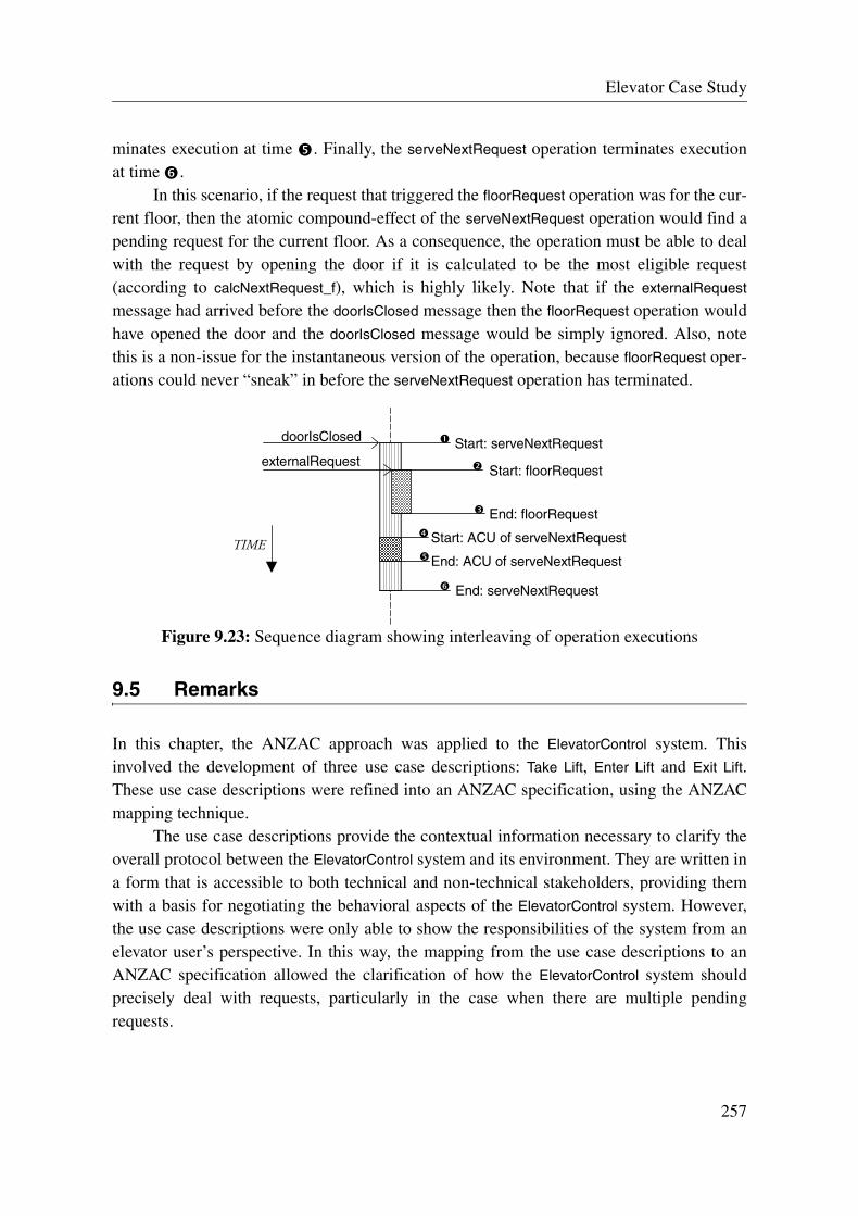
Elevator Case Study
minates execution at time . Finally, the serveNextRequest operation terminates executionat time .
In this scenario, if the request that triggered the floorRequest operation was for the cur-rent floor, then the atomic compound-effect of the serveNextRequest operation would find apending request for the current floor. As a consequence, the operation must be able to dealwith the request by opening the door if it is calculated to be the most eligible request(according to calcNextRequest_f), which is highly likely. Note that if the externalRequest
message had arrived before the doorIsClosed message then the floorRequest operation wouldhave opened the door and the doorIsClosed message would be simply ignored. Also, notethis is a non-issue for the instantaneous version of the operation, because floorRequest oper-ations could never “sneak” in before the serveNextRequest operation has terminated.
Figure 9.23: Sequence diagram showing interleaving of operation executions
9.5 Remarks
In this chapter, the ANZAC approach was applied to the ElevatorControl system. Thisinvolved the development of three use case descriptions: Take Lift, Enter Lift and Exit Lift.These use case descriptions were refined into an ANZAC specification, using the ANZACmapping technique.
The use case descriptions provide the contextual information necessary to clarify theoverall protocol between the ElevatorControl system and its environment. They are written ina form that is accessible to both technical and non-technical stakeholders, providing themwith a basis for negotiating the behavioral aspects of the ElevatorControl system. However,the use case descriptions were only able to show the responsibilities of the system from anelevator user’s perspective. In this way, the mapping from the use case descriptions to anANZAC specification allowed the clarification of how the ElevatorControl system shouldprecisely deal with requests, particularly in the case when there are multiple pendingrequests.
doorIsClosed
externalRequest
End: floorRequest
Start: serveNextRequest
End: ACU of serveNextRequest
Start: floorRequest
End: serveNextRequest
Start: ACU of serveNextRequestTIME
257

Remarks
The ANZAC specification offers a precise description of the ElevatorControl system’sresponsibilities and its interaction protocol with its environment. In particular, it sheds lighton some of the tricky aspects of the concurrent behavior of this system. Furthermore, itabstracts above the stopping and scheduling policy of the elevator using functions in thecorresponding Operation Schemas. The abstraction of these two policies allows them tovary without requiring a change to the specification. However, the specification does notinclude fairness constraints on the scheduling policy, e.g., a request is eventually served.This is because the language is not sufficiently rich to do so. To formalize such a constraint,some form of temporal logic would be required. (It would also be useful to be able to definedeadlines on serving requests, e.g., requests must be served within a certain deadline.)
The ANZAC specification for the elevator control system has an operational feel to it,and therefore it could be perceived as having implementation bias, since it is an implemen-tation in an abstract sense. However, it is arguably easier to use than a purely mathematicalspecification, and it provides an easier and more certain path to an implementation, whichboth prove hard to beat.
Readers that are interested in more examples of elevator systems can find ANZACspecifications for a number of different variations on the one shown in this chapter in[Se02b], e.g., multiple cabins rather than a single cabin, requests that can be cancelled,external requests that have directions, subsystem specifications, etc.
258

Chapter 10:
Conclusion
The central element of this thesis has been the development of a new approach calledANZAC that offers a systematic way to capture the Behavioral Stakeholders Contract andthe Behavioral Design Contract for reactive systems. The ANZAC approach is intended tobe used to communicate to the development team the required behavior of the future sys-tem.
In section 10.1, I restate the main objective of this thesis, give an overview of the gen-eral approach taken in this thesis, and summarize the solution proposed by this thesis. Insection 10.2, I provide a critical review of the proposed solution. In section 10.3, I describesome perceivable areas of future research. Finally, in section 10.3, I make some concludingremarks.
10.1 Summary
The principal objective of this thesis was to improve the state-of-the-art of specificationsthat are used to communicate the behavior of the (future) system to the development team.In addressing the objective, this work initially involved defining the essential requirementsof specifications that could ensure that the development team has a precise, correct andcommon understanding of the way the system is required to behave.
After identifying some requirements, it became apparent that some of them divergedon some issues. Specifically, the need for a description that is justified against the interestsof the stakeholders suggests that the goals and expectations of stakeholders be explicitlystated. However, the need for a “designer-friendly” description suggests that only informa-
259
Realization of the Two Contracts
tion that describes the system’s responsibilities be included, where the inclusion of descrip-tions of stakeholder goals was considered to be too “noisy” and not essential to the task ofthe development team. This divergence led to the conclusion that it was in fact necessary toaddress two potentially different audiences that each have different objectives and needs:stakeholders and designers.
As a result of this reasoning, two general kinds of specifications were distinguishedand perceived to be necessary to address the requirements adequately; one that addressesthe concerns of the designers, providing a precise description of the system responsibilities;and one that addresses the concerns of the stakeholders in general, providing an informaldescription of the agreed goals that the stakeholders have against the system. The first spec-ification is referred to as the Behavioral Design Contract and the second one is referred to asthe Behavioral Stakeholders Contract.
By addressing the requirements with two different specifications, it is necessary toensure that they can be nevertheless coherently combined to satisfy the main objective(stated earlier). Consequently, an explicit bridge between the two specifications was judgedto be necessary. Further motivation for an explicit relationship between the two specifica-tion came from the desire to ensure that the Behavioral Design Contract was justified withrespect to the interests of stakeholders. In this respect, it seemed appropriate to ensure thatthe Behavioral Design Contract could be refined from the Behavioral Stakeholders Con-tract. As a consequence, the formalisms chosen for the two specifications were required tobe compatible along refinement lines.
In terms of selecting and establishing a formalism for these two specifications, twoadditional requirements were proposed: First, the specifications should support an evolu-tionary software development process (which takes into account the fact that the construc-tion and maintenance of the specification is likely to be performed in iterations andincrements). And, secondly, it should be ensured that all proposals could be realized usingmainstream languages and tools.
10.1.1 Realization of the Two Contracts
In this thesis, these two specifications were concretely realized as part of the ANZACapproach. The ANZAC approach defines two work artifacts called the ANZAC use casedescriptions and the ANZAC specification, which express the Behavioral StakeholdersContract and the Behavioral Design Contract, respectively. ANZAC use case descriptionsoffer an informal and usage-oriented description of the concordant goals that the stakehold-ers have against the system. An ANZAC specification offers a precise, operational descrip-tion of the system responsibilities in servicing all possible requests that it can receive overits lifetime.
In the ANZAC approach, the ANZAC use case descriptions are developed followingthe ANZAC use case framework. This framework defines the context, purpose, style and
260

Conclusion
form of an ANZAC use case description, and it provides a goal-based approach to use caseelicitation. Once a number of ANZAC use case descriptions are established, they can berefined to an ANZAC specification. This refinement procedure is (informally) defined bythe ANZAC mapping technique.
An ANZAC specification is developed by the description of three models, which eachexpress a different but complementary view of the system. These three models are called theConcept Model, the Operation Model, and the Protocol Model. The Concept Model definesthe system’s state space in terms of concepts from the problem domain, the OperationModel describes the effect of system operations on the system state, and the Protocol Modeldefines the correct behavior of the system in terms of its (allowable) input protocol.
In terms of support for iterative and incremental development, the ANZAC approachoffers some useful qualities: the interplay between ANZAC use cases and the ANZAC spec-ification lends itself nicely to refinement by iteration, and incremental development can bebased on the units of use cases and operations, which define partial system capability, i.e.,an increment. In terms of an explicit link to mainstream languages and tools, both ANZACuse case descriptions and the ANZAC specification are realized in UML, which is currentlythe most prominent language for modeling software in practice.
In figure 10.1, I provide a side-by-side overview of the ANZAC approach, whichshows the different but complementary focus of ANZAC use case descriptions and theANZAC specification.
Figure 10.1: Overview of the ANZAC use case descriptions and the ANZAC specification
ANZAC use case descriptions ANZAC specification
Objective Define the Behavioral Stakeholders Contract for a reactive system.
Define the Behavioral Design Contract for a reactive system.
Target Audience All stakeholders of the (software) sys-tem under development.
The designers of the (software) system under development.
Description of the System
They offer an informal and usage-ori-ented description of the system. Descriptions are existential rather uni-versal (due to the scenario nature).
It offers a precise, operational description of the system.
Focus Scenarios describing the usage goals of the stakeholders against the system
System behavior in terms of the effect of operations on the system state and the temporal ordering of those operations.
Unit of Increment Use case Operation
Work Artifacts A set of use case descriptions, which each describe a distinct goal of an actor.
The Concept, Operation and Protocol Models, which each represent a distinct but complementary view of the system.
Language Informal, structured natural language (narrative)
Mixture of visual and textual notations: UML class diagram, UML state machine, and UML’s Object Constraint Language
261

10.2 Critical Review
In this section, I examine the strengths and weaknesses of the proposed solution.
10.2.1 Advantages
The ANZAC approach addresses the problems faced by developers in finding languages,tools and techniques that can be used to understand and document the way a system underdevelopment should behave. It offers a useful contrast between informal and formal nota-tions, emphasizing precision and rigor in some contexts, and informality and expression inother contexts. Perhaps the most appealing feature of the approach is the way that it dealswith capturing the necessary information about the future system by using two specifica-tions, which each has a distinct purpose and a different audience. By explicitly separatingthe specifications along the lines of the needs and objectives of each audience, the approachis better able to tackle the overall objective.
The ANZAC approach makes extensive use of the principles of abstraction, projec-tion and decomposition to combat the complexities of specifying the behavior of reactivesystems. And, it offers a systematic approach to the specification of system behavior byensuring that each constraint that it places on the design of the system is aligned with andtraceable to the (system-related) goals of the stakeholders. The approach explicitlydescribes the interface between the system and its environment, and it makes quite someattempt at providing a specification to the development team that gives them all the infor-mation needed to design the system and no more, avoiding under- or over-specification.
The ANZAC approach places a particular focus on the specification of concurrencyand timing constraints, providing a number of guidelines and techniques (e.g., inherent con-currency guideline, divide-by-collaboration technique) and language constraints (e.g., relyexpressions, atomic compound-effects, time-based properties on states and transitions, auto-concurrency) for this purpose. The technique and language proposed for capturing timingconstraints is especially targeted towards understandability; it offers a response to the ques-tion “What is the smallest extension possible to UML state machine so that it can supportthe specification of typical timing constraints on reactive systems?”.
10.2.2 Remaining Problems and Limitations
As much as one would like to believe that there could exist an approach that can do it all(i.e., Brook’s silver bullet), one should be extremely skeptical to believe any such claims ina software world that faces new challenges on every turn. In this regard, I admit that theANZAC approach has a number of limitations and there are still some remaining problemsto address.

Conclusion
The work achieved on concurrency and synchronization constraints is still in anexperimental stage. It is yet to be proved whether the techniques and guidelines proposed inthis work for defining synchronization constraints in Operation Schemas are in fact costeffective. Clearly, providing information on the inherent synchronization needed by the sys-tem to the development team is extremely beneficial. However, in some cases, coming upwith an abstraction that does not bias one concurrency strategy over another is significantlymore difficult than just choosing one strategy. In such cases, the gain in “abstraction” maynot be deemed worth the effort in achieving it.
Still on the subject of concurrency, there are some kinds of constraints that cannot bespecified with ANZAC specifications. In particular, it is not possible to express fairnessconstraints in the language. This point was illustrated with the ANZAC specification for theelevator control system (Chapter 9). Also, it is not possible to specify activity-level atomic-ity constraints—currently it is only possible to define atomicity constraints within opera-tions. Having said that, it is nevertheless important to ensure that any new proposal wouldnot over-complicate the language from a usage perspective.
Although the technique and language chosen for specifying timing constraints is sim-ple and easy to learn and use, it is not able to express all kinds of timing requirements. Inparticular, it is not able to express timing constraints that require timing information onevent arrival times, and that require a means to specify which sub-state of an auto-concur-rent (or auto-orthogonal) state that the constraint applies to. Introducing this informationinto a UML state machine complicates the model and requires unintuitive extensions to itfor that purpose, making it less accessible to developers.
10.3 Future Work
There are four possible directions of future work that are concerned with the ANZACapproach:
• Tool support for ANZAC approach:
There has already been some work performed towards providing tool support for ANZAC specifications. More precisely, there is a syntax and type checker for Operation Schemas called the LGL schema compiler (discussed in Appendix B), and there is a (Java) code generator for the Protocol Model. The LGL schema compiler could be extended with code generation capabilities and integrated with the Protocol Model code generator for the purpose of generating throwaway prototypes. I believe the ability to generate (throwaway) prototypes is extremely important and useful, because it allows the development team to get early and often customer feedback, which has clear advan-tages in a volatile project context.
263

Future Work
With respect to the ANZAC approach in general, it is very important for its usability that there be tool support for enforcing consistency and aiding the refinement activity between ANZAC use case descriptions and ANZAC specifications.
• Specification-based testing:
Closely related to prototype generation, it would be interesting to explore the possibili-ties for generating test oracles from ANZAC specifications. Two main obstacles are per-ceived to lie in the way of this endeavor: finding a way to relate the abstract state space, as defined by the Concept Model, to the concrete state space, as defined by the program static structure (i.e., the implementation data structures); and dealing with the non-deter-minism in OCL.
• Relating ANZAC to Design (Concurrency/Synchronization Mechanisms):
It would be useful to provide support for performing analysis on the synchronization constraints in Operation Schemas, and, as a result, provide some hints to the develop-ment team as to which concurrency control mechanisms would be suitable.In addition, it would be extremely useful to be able to provide support for relating syn-chronization constructs of the Operation and Protocol Models (and usage patterns of synchronization constructs) to particular transaction models, e.g., nested rely expres-sions are mapped to nested transactions, etc.
• Component contracts:
This work has addressed strictly the issues that surround system specification. However, many of the techniques that have been proposed by this work could be reused in the area of component specifications. In fact, it should be possible to enhance the ANZAC spec-ification so that it could be used to define component contracts. In particular, a proposal for enhancing an ANZAC specification with quality of service constraints would be per-tinent. Such an extension would promote a more dynamic notion of contract.Ideally in component evaluation and selection activities, there should be a specification of the required component and specifications for existing components. This means that selection would involve matching the required component contract to an existing com-ponent contract [ABB+01]. Unfortunately, this is a wickedly hard problem in general. So, by providing precise specifications of component behavior, this activity could be facilitated.
• Language for use case frameworks:
In this thesis, I only informally described the ANZAC use case framework. It would however be interesting to come up with a language and/or template for defining use case frameworks in general. In this way, multiple use case frameworks could be defined in a consistent and comparable manner. A recognized use case framework language would be able to focus future suggestions and proposals for new kinds of use cases, forcing
264
Conclusion
writers to clarify the scope, purpose, style, domain, etc. of their proposed use case description.
• Goal-based elicitation of aspects:
It is clear that object-oriented design does not cluster by goals. However, there is cur-rently quite some activity in the development of aspect-oriented approaches for design, i.e., aspect-oriented design. It would be interesting to study the relationship between stakeholder system-usage goals as described using ANZAC use case descriptions and aspect-oriented designs.
10.4 Final Remarks
The ANZAC approach to the specification of reactive system behavior has quite somepromise. It makes use of mainstream languages and tools but draws upon many well estab-lished software engineering techniques and principles. It offers a useful separation of con-cerns between the different work artifacts and addresses not only different modelingconcerns but also different target audiences. Significant parts of the ANZAC approach havebeen successfully taught to students and practitioners and used in a number of small-to-medium sized projects, which include business systems, embedded systems, applicationtools and utilities, and games. Finally, the ANZAC approach has been integrated into theFondue object-oriented development method [Sof02], which offers a process for the fulltreatment of the software development lifecycle.
265

Final Remarks
266

Bibliography
[ABB+01] C. Atkinson, J. Bayer, C. Bunse, E. Kamsties, O. Laitenberger, R. Laqua, D.Muthig, B. Paech, J. Wust, J. Zettel; “Component-Based Product Line Engi-neering with UML”. Addison-Wesley 2001.
[Abr88] J-R. Abrial; “The B tool (proof proving tool)”. In Proceedings of VDM’88:VDM - The Way Ahead. 2nd VDM-Europe Symposium. LNCS (LectureNotes in Computer Science), no. 328, , pp. 86-87, Springer Verlag, 1988.
[Abr96] J-R. Abrial; “The B-Book: Assigning Programs to Meanings”. CambridgeUniversity Press, 1996.
[AF00] B. Anderson, P. Fertig; “Improving Your Use Cases”. Tutorial Notes, OOP-SLA 2000, Conference on Object-Oriented Programming, Systems, Lan-guages, and Applications, 2000.
[AM01] F. Armour, G. Miller; “Advanced Use Case Modeling”. Object TechnologySeries, Addison-Wesley 2001.
[And00] G. Andrews; “Foundations of Multithreaded, Parallel, and Distributed Pro-gramming”. Addison-Wesley, 2000.
[AP98] V. Alagar, K. Periyasamy; “Specification of Software Systems”. GraduateTexts In Computer Science Series, Springer, 1998.
[Atk97] C. Atkinson; “Adapting the Fusion Process to Support the UML”. ObjectMagazine, Sigs Publications, November 1997.
[Bac98] J. Bacon; “Concurrent Programming”. Addison-Wesley, 1998.
[Bar96] J. Barnes; “Programming in Ada 95”. Addison-Wesley, 1996.
[BBC00] M. Buffo, D. Buchs, S. Chachkov; “CoopnTools a Toolkit for the support ofCO-OPN”. Proceedings of the Tools Demonstration of the 21th InternationalConference on Application and Theory of Petri Nets, Aahrus University,June 2000, pp. 2-6.
[BCR00] E. Börger, A. Cavarra, E. Ricobene; “Modeling the Dynamics of UML StateMachines”. ASM 2000 - International Workshop on Abstract State
267

Bibliography
Machines: Theory and Applications; Gurevich, Kutter, Odersky, Thiele(Ed.), LNCS (Lecture Notes in Computer Science), no. 1912, pp. 223-241,Springer Verlag, 2000.
[BCR01] E. Börger, A. Cavarra, E. Ricobene; “Solving Conflicts in UML StateMachines Concurrent States”. Position Paper for the Workshop on Concur-rency Issues in UML. UML 2001 - The Unified Modeling Language: Model-ing Languages, Concepts and Tools, 4th International Conference, Canada,2001.
[BLP+01] R. Baskerville, L. Levine, J. Pries-Heje, B. Ramesh, S. Slaughter; “HowInternet Software Companies Negotiate Quality”. IEEE Computer, pp. 51-57, May 2001.
[BMR93] A. Borgida, J. Mylopolous and R. Reiter; ‘“...And Nothing Else Changes:The Frame Problem in Procedure Specifications”. Proceedings of ICSE-15,pp. 303-314, IEEE Computer Society Press, 1993.
[BMR95] A. Borigda, J. Mylopoulos and R. Reiter; “On the Frame Problem in Proce-dure Specifications”. IEEE Transactions on Software Engineering, vol. 21,no. 10, pp. 785-798, 1995.
[Boe86] B. Boehm; “A spiral model of software development and enhancement”.ACM Software Engineering Notes, vol. 11, no. 4, pp.14-24, 1986.
[Boo94] G. Booch; “Object-Oriented Analysis and Design with Application”. Addi-son-Wesley, 1994.
[BRJ98] G. Booch, J. Rumbaugh, I. Jacobson; “The Unified Modeling Language UserManual”. Addison-Wesley, 1998.
[Bro87] F. Brooks; “No Silver Bullet: Essence and Accidents of Software Engineer-ing”. IEEE Computer, vol. 20, no. 4, pp. 10-19, April 1987.
[Bro95] F. Brooks; “The Mythical Man-Month”. 20th Anniversary Edition, Addison-Wesley, 1995.
[CAB+94] D. Coleman, P. Arnold, S. Bodoff, C. Dollin, H. Gilchrist, F. Hayes, P. Jere-maes; “Object-Oriented Development: The Fusion Method”. Prentice Hall,1994.
[Car95] J. Carroll; “Scenario-based Design: Envisioning Work and Technology inSystem Development”. Wiley, 1995.
[CD94] S. Cook and J. Daniels; “Designing Object Systems: Object-Oriented Model-ling with Syntropy”. Prentice-Hall, 1994.
268

Bibliography
[CF98] A. Cockburn, M. Fowler; “Question time! about use cases”. ACM SIGPLANNotices, vol. 33, issue 10; Proceedings of the conference on Object-orientedprogramming, systems, languages, and applications, 1998.
[Che76] P. Chen; “The Entity-Relationship Model—Toward A Unified View ofData”. ACM Transactions on Database Systems, vol. 1 no. 1, pp. 9-36, 1976.
[CJ93] D. Coleman, P. Jeremaes; “Object-Oriented Development: The FusionMethod”. NTU Course Notes, October, 1993.
[CKM+99a] S. Cook, A. Kleppe, R. Mitchell, J. Warmer, and A. Wills; “Defining theContext of OCL Expressions”. UML ‘99 - The Unified Modeling Language:Beyond the Standard, 2nd International Conference, USA; France & Rumpe(Eds.), LNCS (Lecture Notes in Computer Science), no. 1723, Springer-Ver-lag, 1999.
[CKM+99b] S. Cook, A. Kleppe, R. Mitchell, B. Rumpe, J. Warmer, and A. Wills; “TheAmsterdam Manifesto on OCL”. Technische Universität München, Depart-ment of Informatics, Technical Report, TUM-I9925, 1999.
[CKS+01] V. Crettaz, M. Kandé, S. Sendall, and A. Strohmeier; “Integrating the Con-cernBASE Approach with SADL”. <<UML>> 2001 - The Unified ModelingLanguage: Modeling Languages, Concepts and Tools, 4th International Con-ference, Canada; Gogolla & Kobryn (Ed.), LNCS (Lecture Notes in Com-puter Science), no. 2185, pp. 166-181, Springer Verlag, 2001.
[CL99] L. Constantine, L. Lockwood; “Software for Use: A Practical Guide to theModels and Methods of Usage-Centered Design”. Addison-Wesley, 1999.
[CL01] L. Constantine, L. Lockwood; “Structure and Style in Use Cases for UserInterface Design”. In van Harmelen (Ed.), Object-Modeling and User Inter-face Design, Addison-Wesley, 2001.
[CLD99] P. Coad, E. Lefebvre, J. De Luca; “Java Modeling In Color With UML:Enterprise Components and Process”. Prentice Hall 1999.
[Coc97] A. Cockburn; “Structuring Use Cases with Goals”. Journal of Object-Ori-ented Programming, Sep/Oct, pp. 35-40, and Nov/Dec, pp. 56-62, 1997.
[Coc98] A. Cockburn; “Basic Use Case Template”. October, 1998. Available on http://members.aol.com/acockburn/papers/uctempla.htm
[Coc00] A. Cockburn; “Writing Effective Use Cases”. Addison-Wesley 2000.
[Col95] D. Coleman; “Fusion with use cases: Extending Fusion for requirementsmodeling”. HP Labs, slide presentation 1995.
269

Bibliography
[CY91] P. Coad, E. Yourdon; “Object-Oriented Analysis”. 2nd edition, Prentice-Hall,1991.
[Dav88] A. Davis; “A Comparison of Techniques for the Specification of ExternalSystem Behavior”. Communications of the ACM, vol. 31, no. 9, pp. 1098-1115, September 1988.
[Dav90] A. Davis; “Software Requirements Analysis and Specification”. PrenticeHall, 1990.
[DH94] D. Drusinsky, D. Harel; “On the power of bounded concurrency I: Finiteautomata”. Journal of the ACM, 41(3), pp. 517–539, 1994.
[DH99] W. Damm and D. Harel; “LSCs: Breathing Life into Message SequenceCharts”. Proc. 3rd IFIP Int. Conf. on Formal Methods for Open Object-Based Distributed Systems (FMOODS'99), March 1999.
[Dij68] E. Dijkstra; “Goto statement considered harmful”. Communications ofACM, vol. 11, no. 3, pp. 147-8, 1968.
[Dij76] E. Dijkstra; “A Discipline of Programming”. Prentice-Hall 1976.
[DLF93] A. Dardenne, A. van Lamsweerde, S. Fickas; “Goal-Directed RequirementsAcquisition”. Science of Computer Programming, vol. 20(1-2), pp. 3-50,1993.
[Dou99] B. Douglass; “Real-Time UML: Developing Efficient Objects for EmbeddedSystems”. Second Edition, Object Technology Series, Addison-Wesley,1999.
[DW98] D. D’Souza and A.Wills; “Objects, Components and Frameworks WithUML: The Catalysis Approach”. Addison-Wesley 1998.
[Eas91] S. Easterbrook; “Elicitation of Requirements from Multiple Perspectives”.Ph.D Thesis, Department of Computing, Imperial College of Science, Tech-nology & Medicine, London University, 1991.
[EG00] G. Engels, L. Groenewegen; “Object-Oriented Modeling: A Roadmap”. InFinkelstein (Ed.), The Future of Software Engineering, Special Volume pub-lished in conjunction with ICSE 2000.
[Eme89] E. Emerson; “Temporal and Modal Logic”. In J. van Leeuwen (Ed.), Hand-book of Theoretical Computer Science, Amsterdam, 1989, pp. 995-1072.
270

Bibliography
[FFF99] K. Finney, N. Fenton, and A. Fedorec; “Effects of Structure on the Compre-hensibility of Formal Specifications”. IEEE Proc.-Softw. vol. 146, no. 4,August 1999.
[FFM90] A. Finkelstein, L. Finkelstein, T. Maibaum; “Engineering-In-The-Large:Software Engineering and Instrumentation”, Proceedings of UK IT '90, pp 1-8, 1990.
[Fir99] D. Firesmith; “Use Case Modeling Guidelines”. Proc. 30th Conference onTechnology for Object-Oriented Programming Languages and Systems(TOOLS-30), pp. 184-193, IEEE Computer Society, 1999.
[Flo67] R. Floyd; “Assigning meaning to programs”. In Proceeding of the Sympo-sium in Applied Mathematics: Mathematical Aspects of Computer Science,pp. 19-32, 1967.
[FM01] S. Flake, W. Mueller; “An OCL Extension for Real-Time Constraints”.Advances in Object Modelling with the OCL; Clark and Warmer (Eds.)LNCS (Lecture Notes in Computer Science), no. 2263, Springer Verlag,2001.
[Fow99a] M. Fowler; “Use and Abuse Cases”. Distributed Computing Magazine, 1999(electronically available at http://www.martinfowler.com/articles.html).
[Fow99b] M. Fowler; UML Distilled: Applying the Standard Object Modeling Lan-guage. Second Edition, Addison-Wesley, 1999.
[FP78] N. Francez, A. Pnueli; “A proof method for cyclic programs”. Acta Informat-ica, 9, pp. 133-157, 1978.
[Fuc92] N. Fuchs; “Specification are (preferably) executable”. Software EngineeringJournal, vol. 7, no. 5, pp. 323-334, September 1992.
[GGJ+00] C. Gunter, E. Gunter, M. Jackson, P. Zave; “A Reference Model for Require-ments and Specifications”. IEEE Software, vol. 17 , no. 3, pp. 37-43, May/June 2000.
[GH98] E. Gagnon, L. Hendren; “SableCC - an object-oriented compiler frame-work”. Proceedings of TOOLS 1998, August 1998.
[GHW85] J. Guttag, J. Horning, J. Wing; “An Overview of the Larch Family of Specifi-cation Languages”. IEEE Software, vol. 2 , no. 5, pp. 24-36, September1985.
271

Bibliography
[Gli00] M. Glinz; “Problems and Deficiencies of UML as a Requirements Specifica-tion Language”. Proc. 10th International Workshop on Software Specifica-tion and Design, San Diego, pp. 11-22, 2000.
[GLM01] G. Génova, J. Llorens, P. Martinez; “Semantics of the Minimum Multiplicityin Ternary Associations in UML”. <<UML>> 2001 - The Unified ModelingLanguage: Modeling Languages, Concepts and Tools, 4th International Con-ference, Canada; Gogolla & Kobryn (Ed.), LNCS (Lecture Notes in Com-puter Science), no. 2185, pp. 329-341, Springer Verlag, 2001.
[GM93] M. Gordon, T. Melham; “Introduction to HOL: A Theorem Proving Environ-ment for Higher Order Logic. Cambridge University Press, 1993.
[GPZ93] J. Gannon, J. Purtilo, M. Zelkowitz; “Software Specification : A Comparisonof Formal Methods”. Intellect 1993.
[Gra94] I. Graham; “Beyond the Use Case: Combining task analysis and scripts inobject-oriented requirements capture and business process re-engineering”.Proc. 13th Conference on Technology for Object-Oriented ProgrammingLanguages and Systems (TOOLS-13 Europe), pp. 203-215, Prentice Hall,1994.
[Gri81] D. Gries; “The Science of Programming”. Springer-Verlag, 1981.
[GW89] D. Gause and G. Weinberg; “Exploring Requirements: Quality BeforeDesign”. Dorset House 1989.
[Har88] D. Harel; “On Visual Formalisms”. Communications of the ACM, vol. 31,no. 5, pp. 514-530, May 1988.
[Har92] D. Harel; “Biting the Silver Bullet: Toward a Brighter Future for SystemDevelopment”. IEEE Computer, 25(1), pp. 8-20, January 1992.
[HC91] F. Hayes, D. Coleman; “Coherent models for object-oriented analysis”. InObject-Oriented Programming: Systems, Languages and Applications/Euro-pean Conference on Object-Oriented Programming, A. Paepcke (Ed.), SIG-PLAN Notes 25(11), pp. 171–183, 1991.
[HC01] M. Hammer and J. Champy; “Reengineering the Corporation”. Harperbusi-ness, 2001.
[HCH+98] A. Hamie, F. Civello, J. Howse, S. Kent, R. Mitchell; “Reflections on theObject Constraint Language”. UML 1998 - The Unified Modeling Lan-guage: Beyond the Notation, 1st International Workshop, France; Bezivin
272

Bibliography
and Muller (Eds.), LNCS (Lecture Notes in Computer Science), no. 1618,pp. 137-145, 1998.
[HDF00] H. Hussmann, B. Demuth, F. Finger; “Modular Architecture for a ToolsetSupporting OCL”. UML 2000 — The Unified Modeling Language: Advanc-ing the Standard, 3rd International Conference, UK; Kent & Evans (Ed.),LNCS (Lecture Notes in Computer Science), no. 1939, pp. 278-293,Springer Verlag, 2000.
[Hen98] B. Hendersons-Sellers; “OML: Proposals to Enhance UML”. UML 1998 -The Unified Modeling Language: Beyond the Notation, 1st InternationalWorkshop, France; Bezivin and Muller (Eds.), LNCS (Lecture Notes inComputer Science), no. 1618, Springer Verlag, 1998.
[HG97] D. Harel, E. Gery; “Executable Object Modeling with Statecharts”. IEEEComputer, vol. 30, no.7, pp. 31-42, July 1997.
[HHK98] A. Hamie, J. Howse, S. Kent; “Interpreting the Object Constraint Language”.Proceedings 5th Asia Pacific Software Engineering Conference (APSEC'98), December 2-4, 1998, Taipei Taiwan, IEEE Computer Society, 1998.
[HK98] M. Hitz, G. Kappel; “Developing with UML - Some Pitfalls andWorkarounds”. UML 1998 - The Unified Modeling Language: Beyond theNotation, 1st International Workshop, France; Bezivin and Muller (Eds.),LNCS (Lecture Notes in Computer Science), no. 1618, pp. 9-20, SpringerVerlag, 1998.
[HKV97] D. Harel, O. Kupferman, M. Vardi; “On the Complexity of Verifying Con-current Transition Systems”. CONCUR'97: 8th International Conference ofConcurrency Theory; LNCS (Lecture Notes in Computer Science), no. 1243,pp. 258-272, Springer Verlag, 1997.
[HN96] D. Harel, A. Naamad; “The Statemate Semantics of Statecharts”. In ACMtransactions on software engineering and methodology, vol. 5, no. 4 , 1996.
[Hoa69] C. Hoare; “An axiomatic basis for computer programming”. Communica-tions of the ACM, vol. 12, no. 10, pp. 576-583, 1969.
[Hoa72] C. Hoare; “Proof of Correctness of Data Representations”. Acta Informatica,vol. 1, pp. 271-281, 1972.
[HP85] D. Harel, A. Pnueli; “On the development of reactive systems”. In K.R. Apt,editor, Logics and Models of Concurrent Systems, pp. 477-498, Springer-Verlag, 1985.
273
Bibliography
[HU00] B. Henderson-Sellers, B. Unhelkar; “Open Modeling with UML”. AddisonWesley, 2000.
[Ja95] D. Jackson; “Structuring Z Specifications with Views”. ACM Transactionson Software Engineering and Methodology, vol. 4, no. 4, pp. 365-389, Octo-ber 1995.
[Ja02] D. Jackson; “Alloy: A Lightweight Object Modelling Notation”. ACMTransactions on Software Engineering (to appear), 2002.
[Jac87] I. Jacobson; “Object-Oriented Development In an Industrial Environment”.Proceedings of OOPSLA'87, special issue of SIGPLAN Notices. Vol. 22,No. 12, pp. 183-191, 1987.
[Jac95] I. Jacobson; “Formalizing Use-Case Modeling”. Journal of Object-OrientedProgramming, vol. 8, no. 3, pp. 10-14, 1995.
[Jack83] M. Jackson; “System Development”. Prentice Hall, 1993.
[Jack95] M. Jackson; “Software Requirements and Specification: a lexicon ofpractice, principles and prejudices”. Addison-Wesley, 1995.
[Jack00] M. Jackson; “Problem Frames and Methods: Structuring and Analyzing Soft-ware Development Problems”. Addison-Wesley, 2000.
[Jar99] M. Jarke; “CREWS: Towards Systematic Usage of Scenarios, Use Cases andScenes”. Proceeding of 4th Internationale Tagung Wirtschaftsinformatik(WI'99), Germany, pp. 469-486, 1999.
[JBR99] I. Jacobson, G. Booch, J. Rumbaugh; “The Unified Software DevelopmentProcess”. Addison Wesley, 1998.
[JC95] I. Jacobson and M. Christerson; “A Growing Consensus On Use Cases”.Journal of Object-Oriented Programming, vol. 8, no. 1, pp. 15-19, 1995.
[JCJ92] I. Jacobson, M. Christerson, P. Jonsson, G. Overgaard; “Object-OrientedSoftware Engineering: A Use Case Driven Approach”. Addison-Wesley,1992.
[JEJ95] I. Jacobson, M. Ericsson, Agneta Jacobson; “The Object Advantage: Busi-ness Process Reengineering with Object Technology”. Addison-Wesley,1995.
[Jon83] C. Jones; “Tentative steps toward a development method for interfering pro-grams”. ACM Transactions on Programming Languages and Systems, 5(4),pp. 596-619, 1983.
274

Bibliography
[Jon86] C. Jones; “Systematic Software Development Using VDM”. Prentice Hall,1986.
[Kai95] H. Kaindl; “An Integration of Scenarios with Their Purposes in Task Model-ing”. Proceedings of the Symposium on Designing Interactive Systems: Pro-cesses, Practices, Methods & Techniques (DIS `95), pp. 227-235, ACMPress, 1995.
[Kai99] H. Kaindl; “Difficulties in the Transition from OO Analysis to Design”.IEEE Software, pp. 94-102, September/October 1999.
[KG00] D. Kulak and E. Guiney; “Use Cases: Requirements in Context”. ACMPress, Addison-Wesley, 2000.
[Kie01] J. Kienzle; “Open Multithreaded Transactions: A Transaction Model forConcurrent Object-Oriented Programming”. Ph.D. Thesis EPFL-DI, no2393, Swiss Federal Institute of Technology in Lausanne, Software Engi-neering Lab., 2001.
[KK98] D. Keck, P. Kuehn; “The Feature and Service Interaction Problem in Tele-communications Systems: A Survey”. IEEE Transaction on Software Engi-neering, vol. 24, no. 10, pp. 779-796, 1998.
[KO01] Klasse Objecten; “OCL Tools and Services”. Electronic Resource http://www.klasse.nl/ocl/ocl-services-text.html
[Kor98] T. Korson; “The Misuse of Use Cases”. Object Magazine, May 1998.
[Kov99] B. Kovitz; “Practical Software Requirements: A Manual of Content andStyle”. Manning 1999.
[Lan95] K. Lano; “Formal Object-Oriented Development”. Formal Approaches toComputer Information Technology Series, Springer, 1995.
[Lil99] S. Lilly; “Use case pitfalls: top 10 problems from real projects using usecases”. TOOLS 30, Proceedings of Technology of Object-Oriented Lan-guages and Systems, pp. 174-183, 1999.
[LP99] J. Lilius, I. Paltor; “The semantics of UML state machines”. Turku Centre forComputer Science, Technical Report No 273, May 1999.
[LW00] D. Lefffingwell, D. Widrig; “Managing Software Requirements: A UnifiedApproach”. Object Technology Series, Addison-Wesley, 2000.
[LX99] J. Lee, N. Xue; “Analyzing User Requirements by Use Cases: A Goal-DrivenApproach”. IEEE Software, 16 (4), pp. 92-101, July/August, 1999.
275

Bibliography
[Mas98] B. Massingill; “A Structured Approach to Parallel Programming”. PhD the-sis, Computer Science Department, California Institute of Technology (Tech-nical Report CS-TR-98-04), 1998.
[MB99] R. Malan, D. Bredemeyer; “Functional Requirements and Use Cases”. June1999. Available at http://www.bredemeyer.com/papers.htm
[McD94] J. McDermid; “Requirements analysis: Orthodoxy, fundamentalism and her-esy”. Requirements Engineering: social and technical issues; Jirotka &Goguen (eds.), pp.17-40, Academic Press, 1994.
[Mey85] B. Meyer; “On Formalism in Specifications”. IEEE Software, vol. 2, no. 1,pp. 6-26, 1985.
[Mey90] B. Meyer; “Introduction to the Theory of Programming Languages”. Pren-tice Hall, 1990.
[Mey92a] B. Meyer; “Applying Design by Contract”. IEEE Computer, pp. 40-51, 1992.
[Mey92b] B. Meyer; “Eiffel: The Language”. Prentice Hall, 1992.
[Mey97] B. Meyer; “Object-Oriented Software Construction”. 2nd Edition, PrenticeHall, 1997.
[MO92] J. Martin, J. Odell; “Object-Oriented Analysis and Design”. Prentice-Hall,1992.
[Mor94] C. Morgan; “Programming from Specifications”. 2nd Edition, Prentice Hall1994.
[MOW01] P. Metz, J. O'Brien, W. Weber; “Against Use Case Interleaving”. <<UML>>2001 - The Unified Modeling Language: Modeling Languages, Concepts andTools, 4th International Conference, Canada; Gogolla & Kobryn (Ed.),LNCS (Lecture Notes in Computer Science), no. 2185, pp. 472-486,Springer Verlag, 2001.
[NC00] G. Naumovich and L. Clarke; “Classifying Properties: An Alternative to theSafety-Liveness Classification”. Proceedings of 8th international symposiumon Foundations of Software Engineering for twenty-first century applica-tions, USA. ACM SIGSOFT Software Engineering Notes, vol. 25, no. 6,2000.
[NE00] B. Nuseibeh, S. Easterbrook; “Requirements engineering: a roadmap”. InFinkelstein (Ed.), The Future of Software Engineering, Special Volume pub-lished in conjunction with ICSE 2000.
276
Bibliography
[NKF94] B. Nuseibeh, J. Kramer, A. Finkelstein; “A Framework for Expressing theRelationships Between Multiple Views in Requirements Specifications”. InTransactions on Software Engineering volume 20, number 10, pp. 760-773,October, 1994.
[Nus94] B. Nuseibeh; “A Multi-Perspective Framework for Method Integration”.Ph.D Thesis, Department of Computing, Imperial College of Science, Tech-nology & Medicine, London University, 1994.
[OL82] S. Owicki, L. Lamport; “Proving Liveness Properties of Concurrent Pro-grams”. ACM Transactions on Programming Languages and Systems, vol. 4,no. 3, pp. 455-495, 1982.
[Omg01] OMG Unified Modeling Language Revision Task Force; “OMG UnifiedModeling Language Specification”. Version 1.4, May 2001. http://www.celi-gent.com/omg/umlrtf/
[OR97] J. Odell, G. Ramackers; “Toward a Formalization of OO Analysis”. Journalof OO Programming, pp. 64–68, July 1997.
[OSR+99] S. Owre, N. Shankar, J. Rushby, D. Stringer-Calvert; “PVS System Guide”.Computer Science Laboratory, SRI International, Menlo Park, CA, USA,September 1999.
[Par72] D. Parnas; “A Technique for Software Module Specification with Examples”.Communications of the ACM, vol. 15, no. 5, pp. 330-336, 1972.
[Pau94] L. Paulson; “Isabelle: A Generic Thereom Prover”.LNCS (Lecture Notes inComputer Science), no. 929, Springer Verlag, 1994.
[PC86] D. Parnas, P. Clements; “A Rational Design Process: How and Why to FakeIt”. IEEE Transactions on Software Engineering, Feb. 1986.
[PF02] S. Palmer, J. Felsing; “A Practical Guide to Feature-Driven Development”.Prentice Hall 2002.
[Pre99] Presidents Information Technology Advisory Committee; Report to the Pres-ident “Information Technology Research: Investing in Our Future”. NationalCoordination Office for Computing, Information, and Communications, Feb-ruary 1999. Available at http://www.ccic.gov/ac/report/pitac_report.pdf
[P-J99] M. Page-Jones; “Fundamentals of Object-Oriented Design in UML”. Addi-son-Wesley, 1999.
[Pol97] A. Pols; “Use Case Rules of Thumb: Guidelines and Lessons Learned”.Fusion Newsletter, Feb. 1997.
277

Bibliography
[Poo00] R. Pooley; “Software Engineering and Performance - a roadmap”. In Pro-ceedings of the conference on the future of software engineering, Finkelstein(Ed.), Part of IEEE International Conference on Software Engineering, pp.189-200, 2000.
[Pre97] R. Pressman; “Software Engineering: A Practitioner’s Approach”. 4th Edi-tion, McGraw-Hill, 1997.
[RBP+91] J. Rumbaugh, M. Blaha, W. Premerlani, F. Eddy, and W. Lorenson; “Object-Oriented Modeling and Design”. Prentice Hall 1991.
[Red96] D. Redmond-Pyle; “GUI Design Techniques for OO Projects”. Object-Expert, Nov/Dec 1996.
[RG98] M. Richters, M. Gogolla; “On Formalizing the UML Object Constraint Lan-guage, OCL”. Proc. 17th Int. Conf. Conceptual Modeling (ER'98); Ling,Ram, & Lee (Ed.), LNCS (Lecture Notes in Computer Science), no. 1507,pp. 449-464, Springer Verlag, 1998.
[RG01] J. Ryser, M. Glinz; “Dependency Charts as a Means to Model Inter-ScenarioDependencies”. In Engels, Oberweis and Zündorf (Eds.): Modellierung ‘01Germany; GI-Edition - Lecture Notes in Informatics, Vol. P-1. 71-80, 2001.
[RG02] M. Richters, M. Gogolla; “OCL: Syntax, Semantics, and Tools”. ObjectModeling with the OCL, The Rationale behind the Object Constraint Lan-guage; Clark and Warmer (Eds.) LNCS (Lecture Notes in Computer Sci-ence), no. 2263, Springer Verlag, 2002.
[Ric01] M. Richters; “A Precise Approach to Validating UML Models and OCL Con-straints”. PhD Dissertation, University of Bremen, Germany, 2001.
[Rie96] A. Riel; “Object-Oriented Design Heuristics”. Addison-Wesley, 1996.
[RJB98] J. Rumbaugh, I. Jacobson, G. Booch; “The Unified Modeling Language Ref-erence Manual”. Addison-Wesley, 1998.
[Ros97] R. Ross; “The Business Rule Book: Classifying, Defining and ModelingRules”. V 4.0, Business Rules Solutions Inc. 1997.
[RR00] S. Robertson, J. Robertson; “Mastering the Requirements Process”. Addi-son-Wesley, 2000.
[RS99] D. Rosenberg, K. Scott; “Use Case Driven Object Modeling With UML: APractical Approach”. Addison-Wesley, 1999.
278
Bibliography
[Saa97] M. Saaltink; “The Z/EVES System”. In Proceedings of ZUM'97: The Z For-mal Specification Notation (10th International Conference of Z Users, UK,1997), Bowen, Hinchey, and Till (Eds.); Lecture Notes in Computer Science1212, Springer-Verlag, pp. 72-85, 1997.
[SC92] R. Sharble, S. Cohen; “The Object-Oriented Brewery: A Comparison of TwoObject-Oriented Development Methods.” Software Engineering Notes, vol.18, no. 2, pp. 60-73, 1992.
[Se02a] S. Sendall; “Auction Case Study”. Electronic Resource, available at: http://lglwww.epfl.ch/research/fondue/case-studies/auction/, 2002.
[Se02b] S. Sendall; “Elevator Control System Case Study”. Electronic Resource,available at: http://lglwww.epfl.ch/research/fondue/case-studies/elevator/, 2002.
[SF02] SourceForge; “Dresden OCL Toolkit”. Electronic Resource: http://dresden-ocl.sourceforge.net/
[SG99] A. Simons, I. Graham; “30 Things That Go Wrong in Object Modelling withUML 1.3”. Behavioral Specifications of Businesses and Systems: Kilov,Rumpe and Simmonds (Ed.), Kluwer Academic Publishers, pp. 221-242,1999.
[Sim99] A. Simons; “Use cases considered harmful”. TOOLS-29 Europe, Proceed-ings of Technology of Object-Oriented Languages and Systems, Mitchell,Wills, Bosch and Meyer (Ed.); pp. 194-203, IEEE Computer Society, 1999.
[SK98] I. Sommerville, G. Kotonya; “Requirements Engineering: Processes andTechniques”. Worldwide Series in Computer Science, John Wiley & Son,1998.
[SM89] S. Shlaer, S. Mellor; “An object-oriented approach to domain analysis”.ACM SIGSOFT Software Engineering Notes 14 (5), pp. 66–77, 1989.
[SM92] S. Shlaer, S. Mellor; “Object Lifecycles: Modeling the World in States”.Yourdon Press Computing Series, 1992.
[Smi96] S. Smith; “Formal Justification in Requirements Engineering”. Ph.D Thesis,Department of Computer Science, University of York, 1996.
[Sof02] Software Engineering Lab. (LGL), Swiss Federal Institute of Technology inLausanne; “The Fondue Method”. Electronic Resource, available at: http://lglwww.epfl.ch/research/fondue/, 2002.
[Spi89] J.M. Spivey; “The Z Notation: A Reference Manual”. Prentice Hall, 1989.
279
Bibliography
[SS99a] S. Sendall, N. Guelfi, A. Strohmeier; “Fusion Applied to Distributed Multi-media System Development: the Easy Meeting Case Study”. TechnicalReport EPFL-DI No 99/304, Software Engineering Lab., Swiss Federal Insti-tute of Technology in Lausanne, 1999.
[SS99b] S. Sendall, A. Strohmeier; “UML-based Fusion Analysis”. UML ‘99 - TheUnified Modeling Language: Beyond the Standard, Second InternationalConference, USA; France & Rumpe (Ed.), LNCS (Lecture Notes in Com-puter Science), no. 1723, pp. 278-291, Springer-Verlag, 1999; extended ver-sion also available as Technical Report (EPFL-DI No 99/319).
[SS00a] S. Sendall and A. Strohmeier; “From Use Cases to System Operation Speci-fications”. UML 2000 — The Unified Modeling Language: Advancing theStandard, 3rd International Conference, UK; Kent & Evans (Ed.), LNCS(Lecture Notes in Computer Science), no. 1939, pp. 1-15, Springer Verlag,2000.
[SS00b] S. Sendall, A. Strohmeier; “Enhancing OCL for Specifying Pre- and Post-conditions”. UML 2.0 - The Future of the UML Object Constraint Language(OCL). Workshop of UML 2000 - The Unified Modeling Language:Advancing the Standard, 3rd International Conference, UK, 2000.
[SS01a] S. Sendall, A. Strohmeier; “Specifying Concurrent System Behavior andTiming Constraints Using OCL and UML”. <<UML>> 2001 - The UnifiedModeling Language: Modeling Languages, Concepts and Tools, 4th Interna-tional Conference, Canada; Gogolla & Kobryn (Ed.), LNCS (Lecture Notesin Computer Science), no. 2185, pp. 391-405, Springer Verlag, 2001.
[SS01b] S. Sendall, A. Strohmeier; “Merging Fine-Grained and Coarse-Grained Con-current Behavior Specifications in UML”. Position Paper for the Workshopon Concurrency Issues in UML. UML 2001 - The Unified Modeling Lan-guage: Modeling Languages, Concepts and Tools, 4th International Confer-ence, Canada, 2001.
[SS02] S. Sendall, A. Strohmeier; “Using OCL and UML to Specify System Behav-ior”. Object Modeling with the OCL, The Rationale behind the Object Con-straint Language; Clark and Warmer (Eds.) LNCS (Lecture Notes inComputer Science), no. 2263, pp. 250-279, Springer Verlag, 2002.
[Ste01] P. Stevens; “On Use Cases and Their Relationships in the Unified ModellingLanguage”. Fundamental Approaches to Software Engineering (FASE2001), part of the Joint European Conferences on Theory and Practice of
280

Bibliography
Software (ETAPS 2001); Hussmann (Ed.), LNCS (Lecture Notes in Com-puter Science), no. 2029, pp. 140-155, Springer Verlag, 2001.
[StS01] A. Strohmeier, S. Sendall; “Operation Schemas and OCL”. Technical Report(EPFL-DI No 01/358), Software Engineering Lab., Swiss Federal Institute ofTechnology in Lausanne, 2001.
[SW98] G. Schneider, J. Winters; “Applying Use Cases: A Practical Guide”. Addi-son-Wesley,1998.
[TD97] R. Thayer, M. Dorfman (eds.); Software Requirements Engineering. 2ndEdition, IEEE Comp. Soc. Press, 1997.
[VS99] K. van den Berg and A. Simons; “Control flow semantics of use cases inUML”. Information and Software Technology, 41(10), pp. 651-659, Elsevier,1999.
[W-B92] R. Wirfs-Brock; “Characterizing Your Objects”. Smalltalk Report, vol. 2, no.5, February, 1992. Available at: http://www.wirfs-brock.com/pages/resources.html
[W-B94a] R. Wirfs-Brock; “The Art of Designing Meaningful Conversations”. Small-talk Report, February, 1994. Available at: http://www.wirfs-brock.com/pages/resources.html
[W-B94b] R. Wirfs-Brock; “How Designs Differ”. Journal of Object-Oriented Pro-gramming, Report on Object Analysis and Design, vol. 1, no. 4, November1994. Available at: http://www.wirfs-brock.com/pages/resources.html
[WG00] A. Wegmann, G. Genilloud; “The Role of ‘Roles’ in Use Case Diagrams”.UML 2000 — The Unified Modeling Language: Advancing the Standard,3rd International Conference, UK; Kent & Evans (Ed.), LNCS (LectureNotes in Computer Science), no. 1939, pp. 210-224, Springer Verlag, 2000.
[Wie98] R. Wieringa; “A Survey of Structured and Object-Oriented Software Specifi-cation Methods and Techniques”. ACM Computing Surveys, vol. 30, no. 4,December 1998.
[Win83] J. Wing; “A Two-tiered Approach to Specifying Programs”. TechnicalReport TR-299, Massachusetts Institute of Technology, Laboratory for Com-puter Science, 1983.
[Wir71] N. Wirth; “Program Development by Stepwise Refinement”. Communica-tions of the ACM, vol. 14, no. 4, pp. 221-227, 1971.
281

Bibliography
[WK98] J. Warmer, A. Kleppe; “The Object Constraint Language: Precise ModelingWith UML”. Addison-Wesley 1998.
[WK00] Y. Wang, G. King; “Software Engineering Processes: Principles and Applica-tions”. CRC Press, 2000.
[WM99] R. Wirfs-Brock, A. McKean; “The Art of Writing Use Cases”. TutorialNotes, OOPSLA 1999, Conference on Object-Oriented Programming, Sys-tems, Languages, and Applications, 1999.
[WN97] WordNet ® 1.6, © 1997, Princeton University: ftp://clarity.princeton.edu/pub/wordnet/wn1.6unix.tar.gz
[WWW90] R. Wirfs-Brock, B. Wilkerson, L. Wiener; “Designing Object-Oriented Soft-ware”. Prentice Hall, 1990.
[Zav01] P. Zave; “Requirements for Evolving Systems: A Telecommunications Per-spective”. In Proceeding of RE ‘01 (Keynote Address), 5th IEEE Interna-tional Symposium on Requirements Engineering, pp. 2-9.
282

Appendix A:
Object Constraint Language
This appendix provides a summary of the Unified Modeling Language’s constraint lan-guage called the Object Constraint Language (OCL). It details the various elements of OCL,giving an idea how one might write OCL expressions. OCL can be useful for writing invari-ants, pre- and postconditions, and constraints in general. This summary is based on the OCLspecification, which is chapter 6 of the UML 1.4 specification [Omg01].
Introduction
OCL is a formal language for writing expressions whose principles are based on set theoryand first-order predicate logic. OCL can be used in various ways to add precision to UMLmodels beyond the capabilities of graphical diagrams. For instance, a UML class diagrammay not be able to express all aspects of a specification that are necessary for it to be com-plete. Thus, modelers can use OCL to specify application-specific constraints in their UMLmodels.
Traditionally, constraints on models are written in natural language. However, naturallanguage is prone to ambiguities and imprecision. Many formal languages have been pro-posed for reducing these problems. The disadvantage of traditional formal languages is thatthey require a strong mathematical background, and they can prove difficult to use for thosebusiness and system modelers who do not have such a background. OCL has been devel-oped to fill this gap. It is a formal language, its formal semantics is given in [Ric01], that istargeted toward being easy to read and write. It was originally developed as a business mod-eling language within the IBM Insurance division, and it has roots that go back to the Syn-tropy method [CD94].
283

Two common uses of OCL are the statement of system invariants on class models andthe definition of pre- and postconditions for operations/methods. OCL is a declarative lan-guage. An OCL expression has no side effects, i.e. its evaluation cannot alter the state of thecorresponding entity. OCL is a typed language, so that each OCL expression has a type. Tobe well formed, an OCL expression must conform to the type conformance rules of the lan-guage. OCL provides elementary types, like Boolean, Integer, etc., includes collections, likeSet, Bag, and Sequence, and has an assortment of predefined operators on these basic types.It also allows user-defined types which can be any type defined in a UML model, in particu-lar classes. OCL uses an object-oriented-like notation to access properties, attributes, andfor applying operators.
The LanguageIn this section, I describe the different elements of OCL. The description is based on chapter6 of the UML specification [Omg01]. For the purposes of explaining the different aspects ofOCL, figure A.1 shows a class diagram that will be used as the reference example through-out this summary.
Figure A.1: Example UML Class Diagram
name: Stringrank: Integer
Team
Person
name: String
Club1..*
0..1
0..* 1
name: Stringbudget : Integer
Union
0..*
1
heads0..1
president1
Membership
1..*
isMemberOf 0..*
member
Player NonPlayer
pNum:Integer
supports
supporters 0..*
joinDate: Dateexpiry: Date
name: Stringage: Integer
position: Positionheight: Integerweight: IntegercanPlayLock (): Boolean
day: Daymonth: Monthyear: Year
Date
wingfullbackcenterhalfbackrowlockfrontrowreserve
Position<<enumeration>>
<<datatype>>
changeAge ()
284

Object Constraint Language
Context
Each OCL expression is written in the context of an instance of a specific type. The pre-defined identifier self refers to this instance. In OCL, the context is explicitly declared1. Forexample, we could specify an invariant for all persons, constraining the model shown infigure .context Person
inv: self.age >= 15
This is an invariant for all objects of the class Person; it states that a person is always greaterthan or equal to 15. self.age is a navigation expression that results in the value of the age
attribute of the person denoted by self. It is equivalent to the following.context p: Person
inv: p.age >= 15
This form gives an explicit name, p, rather than self. It is also equivalent to the following.context p: Person
inv noUnderAgePerson: p.age >= 15
where a name is given to the invariant, noUnderAgePerson. OCL also allows you to specifypre- and postconditions. They have the following form.context Player::canPlayLock (): Boolean
pre: self.weight > 100
post: result = (self.height > 190)
In this example, the context is Player, where the precondition and postcondition of it’smethod canPlayLock is specified. The method does not have any parameters and its returntype is Boolean. Note that result is a predefined identifier of OCL that represents the result ofa function. The type of result matches the return type, which is suffixed at the end of theparameter list of the method, i.e., Boolean in the case of the canPlayLock method.
The precondition of the canPlayLock method states that the weight of the player isassumed to be over 100 (kilograms) and the postcondition states that the result of themethod is true if the height of the player is over 190 (centimeters), otherwise it is false.
Types
Each OCL expression is written in the context of a UML model. All types from the UMLmodel can be used in OCL. Also, OCL has a number of predefined elementary types: Bool-ean, Integer, Real, String, Enumeration, where each one has a set of predefined features andproperties. The first four are similar to the primitive types that you would find in a languagelike Java. Enumerations are Datatypes in UML and have a name. An enumeration defines anumber of enumeration literals, that are the possible values of the enumeration. Within
1. Note that in the case of an Operation Schema, the context is implicit: it is an instance of the system thatowns the operation.
285

OCL, one can refer to the value of an enumeration. For example, given an enumeration typePosition (see figure ) with values wing, fullback, center, half, backrow, lock, frontrow, or reserve,you can use them in the following way.context Player
inv: self.position = Position::frontrow
This invariant would mean that all players play in the frontrow position. Note the enumera-tion is accessed by prefixing the literal with its type, followed by “::”.
All types need to conform to a number of rules defined in [Omg01]. OCL also has anumber of collection types. The collection types play an important role in OCL expressions,as we will see in the discussion of navigation expressions in OCL. Collection is the abstractsupertype of all collection types in OCL. Collection has three concrete subtypes: Set, Bag andSequence. Set is the mathematical set; it does not contain duplicate elements and is unor-dered. Bag is like a set, i.e., it does not have an order, but it may contain duplicates (i.e., thesame element may be in a bag more once). Sequence is like a bag, i.e., it may contain dupli-cates, but the elements of a sequence are ordered. In OCL, a collection can be specified byliterals. Below are several examples of collection literals. Note that comments in OCL arewritten following two successive dashes (minus signs). Everything immediately followingthe two dashes up to and including the end of line is part of the comment.
Set {1, 2, 5, 88} -- a set of integers
Set {‘Josh’, ‘Richard’, ‘Krusher’} -- a set of strings
Sequence {1, 3, 45, 2, 3} -- a sequence of integers
Sequence {1..10} -- a sequence of integers
Bag {1, 3, 45, 2, 3} -- a bag of integers
Bag {1, 2, 3, 3, 45} -- an identical bag to the one directly above
OCL has many predefined operations for its collections. Consistent with the definition ofOCL as an expression language, collection operations never change the collection that it isapplied to, instead they result in values that indicate a particular property of the collection orthey project the result into a new collection. Some collection operations are specific to aparticular collection type, e.g., Set, and some collection operations can be used for all col-lection types. See [WK98, Omg01] for a description of all collection operations. Below, Ibriefly explain and give examples of a few of the collection operations available in OCL.Note that the arrow operator is used only on collections, in postfix style, i.e., the operationfollowing the arrow is applied to the previous “term”.
Selecting in a collection: select
colOfAllTeams -> select (t | t.rank <= 5)
-- t iterates through the teams of the colOfAllTeams-- selecting all those who are ranked in the top 5.
Excluding from a collection: reject
286

Object Constraint Language
colOfPlayers -> reject (p | p.canPlayLock())
-- the collection of all players of colPlayers that can not-- play the lock position.
Collecting the values yielded by an expression: collect
colOfPersons -> collect (p | p.age)
-- ages are collected, not persons. The result is a bag of Integers.
Projection on an attribute can be used as a shorthand for collectcolOfPersons.age
-- equivalent to the expression above
Conversion of a bag to a set, by eliminating duplicates: asSet
bagOfIntegers -> asSet ()
-- removes duplicates and type converts to a set of integers
All objects meet the expression (universal quantification): forAll
colOfPlayers -> forAll (p | p.weight > 60)
-- true if all players in colOfPlayers are heavier than 60 (Kilograms).
Existence of an object that meets the expression (existential quantification): exists colOfPlayers -> exists (p | p.position = Position::center)
-- true if at least one player in colOfPlayers plays the center position.
Asserting that an element is a member of a collection: includes
colOfPlayers -> includes (josh);
-- true if josh is a member of colOfPlayers
Asserting that an element is not a member of a collection: excludes
colOfPlayers -> excludes (david);
-- true if david is not a member of colOfPlayers
Existence of a single object: one colOfPlayers -> one (p | p.height > 200)
-- true if and only if one player of colOfPlayers-- is taller than 200 (centimeters).
Selecting an object: any
colOfPlayers -> any (p | p.weight < 80)
-- results in any player of colOfPlayers that is under 80 (kilograms).
Size of the collection: size
colOfPlayers -> size () = 5
-- results in true if there are 5 players in colOfPlayers.
State of emptiness of the collection: isEmpty
colOfPlayers -> isEmpty ()
-- results in true if there are no players in colOfPlayers-- (i.e., the collection is empty).
287

OCL Operators
The precedence order for the operations, starting with highest precedence, in OCL is:
• @pre • dot and arrow operations: ‘.’ and ‘->’• unary ‘not’ and unary minus ‘-’• ‘*’ and ‘/’• ‘+’ and binary‘-’• ‘if’ ... ‘then’ ... ‘else’ ... ‘endif’• ‘<’, ‘>’, ‘<=’, ‘>=’• ‘=’, ‘<>’• ‘and’, ‘or’ and ‘xor’• ‘implies’
Parentheses ‘(’ and ‘)’ can be used to change precedence.For example, the expression in the following invariant,context Player
inv: self.position = Position::half implies self.weight < 100and self.age > 300 / 10 or not self.canPlayLock() <> true
should be interpreted in the following way (using parenthesis to show precedence):inv: ((self.position) = Position::half) implies ((((self.weight) < 100)
and ((self.age) > (300 / 10))) or ((not (self.canPlayLock())) <> true)))
Accessing Properties of Objects
OCL expressions can refer to types, classes, interfaces, and datatypes, and to all propertiesof objects. A property is one of the following: an Attribute, an AssociationEnd, an Opera-tion or a Method with isQuery being true (the rule guarantees that OCL expressions have noside-effects). For example, josh.name accesses the attribute name of the person josh, andjosh.canPlayLock () accesses the canPlayLock method of the person josh. Starting from a spe-cific object, we can navigate an association to refer to other objects. To do so, we refer to therole name of the opposite association-end; it is written in the following form:
object.rolename
The value of this expression is the set of objects on the other side of the association. When arolename is missing, the name of the type, starting with a lowercase character is usedinstead. For example, to find all the teams in a given club c, we could write the followingexpression:
c.team
this expression accesses the association role at the opposite end of the composition associa-tion, and results in the collection of objects on the other end of the association.
288

Object Constraint Language
The objects of an association class can be accessed by navigation using the name ofthe association class, starting with a lowercase character. For example, to find all the mem-bership objects that the person, josh, has with his clubs, we could write the followingexpression:
josh.membership
Single navigation results in a set, i.e., one application of the dot operator. A combined navi-gation results in a bag1. Navigation over associations adorned with {ordered} results in asequence. If the multiplicity of the association end is 0..1 then the expression results in anobject. However, such an expression can be treated like it results in a set as well. For exam-ple, given a person p, we could write the following expression:
p.heads -> notEmpty () implies p.heads.name = ‘Canterbury’
this expression shows the “double life” of the expression p.heads.A qualified association can be navigated like a normal association, or one can navi-
gate it by providing the key. For example, given a team allBlacks, and a key 7, which is aposition number (pNum), we could write the following expression.
allBlacks.player[7]
In this example, the result would have the same result as navigating an association end withmultiplicity 0..1; i.e., we could treat it as an object or a set.
Complex Expressions
Properties can be combined to make more complicated expressions. An important rule isthat an OCL expression always evaluates to an object or value of a specific type, or to a col-lection of objects of a specific type. After obtaining a result, one can always apply anotherproperty to get a new result value. Therefore, each OCL expression can be read and evalu-ated left-to-right. For example, given a union u, we could write the following expression:
u.club.team -> select (t | t.rank <= 5) -> asSet ().player[15] -> forall (p |p.weight > 100 and p.heads->isEmpty ())
Breaking up the explanation of this expression, the select operation results in the bag allteams that are ranked in the top 5 of all the clubs of the union u. The resulting bag has theasSet operation applied to it, resulting in set. To this set, an implicit collect operation isapplied; it uses the key 15 for the qualified association. The resulting set of players that havea position number of 15 has a forall operation applied to it. The forall operation results intrue if all the players in the set have a weight greater than 100 (kilograms) and are not thepresident of a club.
Predefined Properties on All Objects
OCL defines a number of predefined properties for objects. These include:
1. This is true only if more than one of the association ends (used in the navigation expression) has an upperrange of multiplicity greater than 1.
289

Equality: object = (object2: OclAny): Boolean
results in true if object is the same object as object2. For example, given p1 and p2 of classPerson, we could write the following expression:
p1 = p2
which would result in true if p1 references the same person as p2, false otherwise.
Type equality: oclIsTypeOf (t: OclType): Boolean
results in true if the target object is of type t. For example, given josh, we could write the fol-lowing expression:
josh.oclIsTypeOf (Player)
which would result in true if josh is of class Player, false otherwise.
Subtype equality: oclIsKindOf (t: OclType): Boolean results in true if the target object is of type t or one of the supertypes. For example, givenjosh is of class Player, then the following expression would result in true.
josh.oclIsTypeOf (Person)
Object creation: oclIsNew (): Boolean
results in true if the object is newly created. It only makes sense in a postcondition. Forexample, as part of a postcondition, we could write the following expression:
blackTeam.oclIsNew () -- blackTeam is an object of class Team
which would result in true if blackTeam was created by the corresponding operation.
Preconditions and Postconditions
In a postcondition, an expression or sub-expression can be evaluated at the time immedi-ately before or immediately after the execution of the operation/method. Thus, one can referto two values for each property of an object:
• the value of the property at the start of the operation,• the value of the property upon completion of the operation.
The value of a property in a precondition is always the one at the start of the operation. In apostcondition, to refer to the value of a property at the start of the operation, one has to post-fix the property name with the suffix @pre. For example, the incAge method of Person,which increments the age of the target object, could be specified using OCL in the followingway.context Person::incAge ()
pre: self.age > 15
post: self.age = self.age@pre + 1
The incAge method does not have any parameters and it does not have a return type. Theprecondition states that the age (attribute) of the person is greater than 15 and the postcondi-tion states that the age (attribute) of the person (denoted by self) is one greater after themethod than it was before the execution of the method, where the post-value of age is
290
Object Constraint Language
self.age and its pre-value is self.age@pre. Note that navigation expressions are also subject topre- and post-values. For example, given john is of class nonPlayer in a postcondition:
post: [email protected]>forall(c | [email protected](1, 1) = ‘W’)
this would evaluate to true if all the teams that john supported, before the execution of theoperation, have clubs, where the navigation is evaluated after execution, that have names,where the navigation is evaluated before execution, that start with the letter ‘W’. In this way,combined navigations can get quite confusing if one does not take care.
Evaluation Semantics
The evaluation of an OCL expression is instantaneous. This means that the states of objectsin a model cannot change during evaluation. In the context of pre- and postconditions, thismeans that OCL is only capable of specifying sequential operations. Note that in Chapter 6I propose a model that allows truly concurrent operations.
291

292

Appendix B:
Tool Support
This appendix provides a brief overview of the LGL Schema Compiler, which is a tool thatis capable of syntax and type checking Operation Schemas (as defined in Chapter 6). It alsoprovides the grammar for Operation Schemas, which is taken directly from the tool specifi-cation.
Overview of LGL Schema CompilerThe LGL Schema Compiler is a syntax and type checker for Operation Schemas. It takes asinput an XMI file, generated by Rational Rose (Unisys XMI generator add-in), and a textfile, which holds an Operation Schema. The tool indicates whether the supplied OperationSchema is syntax correct, according to the grammar shown below, and if this is the case, itchecks to see that it is type correct using the supplied XMI file to retrieve type information.Note that the XMI file represents the Concept Model of the corresponding system (drawngraphically in Rose).
The LGL Schema Compiler is based upon the Dresden OCL Toolkit [SF02]. TheDresden OCL Toolkit is a modular toolkit for OCL support. The Dresden OCL Toolkit isbased on the OCL compiler developed by Frank Finger at the Dresden University of Tech-nology [HDF00], whose parser is built using the tool SableCC [GH98].
The task of developing the LGL Schema Compiler involved:
• Extracting type information from the XMI file, which involved interpreting the exten-sions to UML made by the Concept Model (i.e., stereotypes).
• Updating the OCL 1.3 grammar of the Dresden OCL Toolkit to be OCL 1.4 compli-ant.
293

• Defining a grammar for Operation Schemas, which involved dealing with the pro-posed language extensions to OCL, Operation Schema clauses, Parameterized Predi-cates, and Functions (which are all described in Chapter 6).
• Type checking an Operation Schema by walking a syntax tree generated by SableCCcode (given the grammar file that is similar to the one shown below).
Operation Schema Grammar
The following grammar is based on the one used for the LGL Schema Compiler. It is pre-sented in two parts: Tokens and Productions, following the SableCC input grammar require-ments.
Tokens
dot = '.';arrow = '->';not = 'not';mult = '*';div = '/';plus = '+';minus = '-';
colon=':';
operation='Operation';description='Description';notes='Notes';use_cases='Use Cases';scope='Scope';messages='Messages';new='New';aliases = 'Aliases';t_pre = 'Pre';t_post = 'Post';
throws='Throws';t_time = 'pre';t_pre_au = 'preAU' ;t_post_au = 'postAU';t_rd= 'rd';t_rely = 'rely';t_fail = 'fail';t_endre = 'endre';fun = 'Function';predicate = 'Predicate';body = 'Body';shared = 'Shared';import ='import';is = 'Is';context = 'context';t_inv = 'inv';
equal = '=';n_equal = '<>';lt = '<';gt = '>';lteq = '<=';gteq = '>=';
and = 'and';or = 'or';
294

Tool Support
xor = 'xor';implies = 'implies';
l_par = '(';r_par = ')';l_squarebracket = '[';r_squarebracket = ']';l_brace = '{';r_brace = '}';
semicolon = ';';dcolon = '::';comma = ',';channel = '#';at = '@';bar = '|';ddot = '..';apostroph = ''';assign = '::=';
t_let = 'let';t_in = 'in';t_if = 'if';t_then = 'then';t_elsif = 'elsif';t_else = 'else';endif = 'endif';t_and = '&';
t_set = 'Set';t_bag = 'Bag';t_sequence = 'Sequence';t_collection = 'Collection';
bool = 'true' | 'false';
impl_arrow = '=>' ;all = 'all' ;
simple_type_name = uppercase (lowercase | digit | uppercase | '_')* ;
name = lowercase (lowercase | digit | uppercase | '_')*;
int = number;real_num = number '.' number;string_lit = ''' s_char_sequence? ''';back_slash = '\' ;
Productions
in = include_file* choice* opn_schema? ;
include_file = import file_name semicolon ;
choice=funct |funct_body |pred;
file_name =simple_type_name colon back_slash name file_name_tail* back_slash name dot? name?;
file_name_tail = back_slash name ;
opn_schema=opn_decldesc_decl?notes_decl?use_cases_decl?scope_decl?shared_decl?messages_decl?
295

new_decl?aliases_decl?pre_decl?post_decl? ;
// Operation clause -- start
opn_decl=operation colon system_class_name dcolon operation_name l_par parameter_list? r_par semicolon;
parameter_list=parameter parameter_list_tail*;
parameter_list_tail=comma parameter;
parameter=entity_declaration |actor_instance_declaration;
actor_instance_declaration=name colon actor_class_name;
system_class_name=simple_type_name;
operation_name=name;
actor_class_name=simple_type_name;
entity_declaration=name colon type_name;
// Operation clause -- end
// Description and Notes clauses -- start
desc_decl=description colon text_body;
notes_decl=notes colon text_body;
text_body=line semicolon;
// Description and Notes clauses -- end
// Use Cases clause -- start
use_cases_decl=use_cases colon use_cases_list?;
use_cases_list =use_case_with_semicolon*;
use_case_with_semicolon =use_case_numbers semicolon;
use_case_numbers =simple_type_name |simple_type_name dcolon l_brace uc_number_list* r_brace ;
uc_number_list =int semicolon;
// Use Cases clause -- end
// Scope clause -- start
scope_decl=
296

Tool Support
scope colon name_list?;
name_list=name_list_element semicolon name_list_tail*;
name_list_tail=name_list_element semicolon;
name_list_element=simple_type_name |association |object_name colon simple_type_name;
object_name=name;
association=simple_type_name? l_par role_name_component? simple_type_name
comma role_name_component? simple_type_name association_tail* r_par |association_name;
role_name_component=role_name colon;
association_tail=comma role_name_component? simple_type_name;
role_name=name;
association_name=simple_type_name;
// Scope clause -- end
//Shared clause --start
shared_decl =shared colon shared_item_with_semicolon* ;
shared_item_with_semicolon =shared_item semicolon ;
shared_item =association |simple_type_name ;
//Shared clause --end
// Messages clause -- start
messages_decl=messages colon actor_with_msgs_list;
actor_with_msgs_list =actor_with_msgs_with_semicolon*;
actor_with_msgs_with_semicolon =actor_with_msgs semicolon;
actor_with_msgs =actor_class_name dcolon l_brace msg_name_list* r_brace ;
msg_name_list =msg_name throws_with_exceptions? semicolon;
throws_with_exceptions =throws exception_msgs;
exception_msgs =msg_name exception_msgs_tail*;
exception_msgs_tail =comma msg_name ;
msg_name=
297
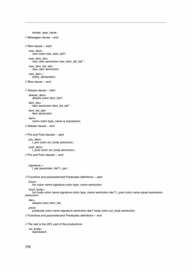
simple_type_name ;
// Messages clause -- end
// New clause -- start
new_decl=new colon new_item_list?;
new_item_list=new_item semicolon new_item_list_tail* ;
new_item_list_tail=new_item semicolon;
new_item =entity_declaration;
// New clause -- end
// Aliases clause -- start
aliases_decl=aliases colon item_list?;
item_list=item semicolon item_list_tail* ;
item_list_tail=item semicolon;
item=name colon type_name is expression;
// Aliases clause -- end
// Pre and Post clauses -- start
pre_decl=t_pre colon ocl_body semicolon ;
post_decl=t_post colon ocl_body semicolon ;
// Pre and Post clauses -- end
signature =l_par parameter_list? r_par ;
// Functions and parameterized Predicates definitions -- start
funct=fun colon name signature colon type_name semicolon;
funct_body=fun body colon name signature colon type_name semicolon dec? t_post colon name equal expression
semicolon;
dec=aliases colon item_list;
pred=predicate colon name signature semicolon dec? body colon ocl_body semicolon;
// Functions and parameterized Predicates definitions -- end
// The rest is the OCL part of the productions
ocl_body=expression;
298

Tool Support
expression =let_expression* logical_expression ;
if_expression =t_if expression t_then expression else_branch;
else_branch =t_else expression endif |t_elsif expression t_then expression else_branch |endif;
rely_expr =t_rely expression t_then ocl_body fail_branch* last_fail? t_endre ;
fail_branch =t_fail expression t_then ocl_body ;
last_fail =t_fail ocl_body;
logical_expression =logical_expression logical_operator relational_expression |relational_expression ;
relational_expression =relational_expression relational_operator additive_expression |additive_expression ;
additive_expression =additive_expression additive_operator multiplicative_expression |multiplicative_expression ;
multiplicative_expression =multiplicative_expression multiplicative_operator unary_expression |unary_expression ;
unary_expression =unary_operator postfix_expression |postfix_expression |composite_value;
// Composite Values -- start
composite_value =aggregate ;
// Composite Values -- end
// Aggregates -- start
aggregate =qualifier_aggregate? l_par aggregate_item? aggregate_tail* r_par ;
qualifier_aggregate =simple_type_name apostroph ;
aggregate_tail =comma aggregate_item ;
aggregate_item =name_with_impl_arrow expression;
name_with_impl_arrow =name impl_arrow ;
// Aggregates -- end
postfix_expression =primary_expression postfix_expression_tail* all_part? |literal;
all_part =dot all ;
299
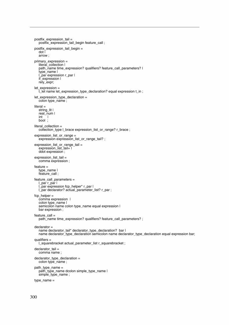
postfix_expression_tail =postfix_expression_tail_begin feature_call ;
postfix_expression_tail_begin =dot |arrow ;
primary_expression =literal_collection |path_name time_expression? qualifiers? feature_call_parameters? |type_name |l_par expression r_par |if_expression |rely_expr;
let_expression =t_let name let_expression_type_declaration? equal expression t_in ;
let_expression_type_declaration =colon type_name ;
literal =string_lit |real_num |int |bool ;
literal_collection =collection_type l_brace expression_list_or_range? r_brace ;
expression_list_or_range =expression expression_list_or_range_tail? ;
expression_list_or_range_tail =expression_list_tail+ |ddot expression ;
expression_list_tail =comma expression ;
feature =type_name |feature_call ;
feature_call_parameters =l_par r_par |l_par expression fcp_helper* r_par |l_par declarator? actual_parameter_list? r_par ;
fcp_helper =comma expression |colon type_name |semicolon name colon type_name equal expression |bar expression ;
feature_call =path_name time_expression? qualifiers? feature_call_parameters? ;
declarator =name declarator_tail* declarator_type_declaration? bar |name declarator_type_declaration semicolon name declarator_type_declaration equal expression bar;
qualifiers =l_squarebracket actual_parameter_list r_squarebracket ;
declarator_tail =comma name ;
declarator_type_declaration =colon type_name ;
path_type_name =path_type_name dcolon simple_type_name |simple_type_name ;
type_name =
300

Tool Support
path_type_name |collections ;
collections =collection_type l_par postfix_expression r_par;
collection_type =t_set |t_bag |t_sequence |t_collection;
path_name =path_type_name dcolon name |name ;
time_expression =at times ;
times =t_time |t_pre_au |t_post_au |t_rd ;
actual_parameter_list =expression actual_parameter_list_tail* ;
actual_parameter_list_tail =comma expression ;
logical_operator =and |t_and |or |xor |implies;
relational_operator =equal |n_equal |gt |lt |gteq |lteq ;
additive_operator =plus |minus;
multiplicative_operator =mult |div;
unary_operator =minus |not;
actual_parameters=name actual_parameters_tail*;
actual_parameters_tail=comma name;
301

302
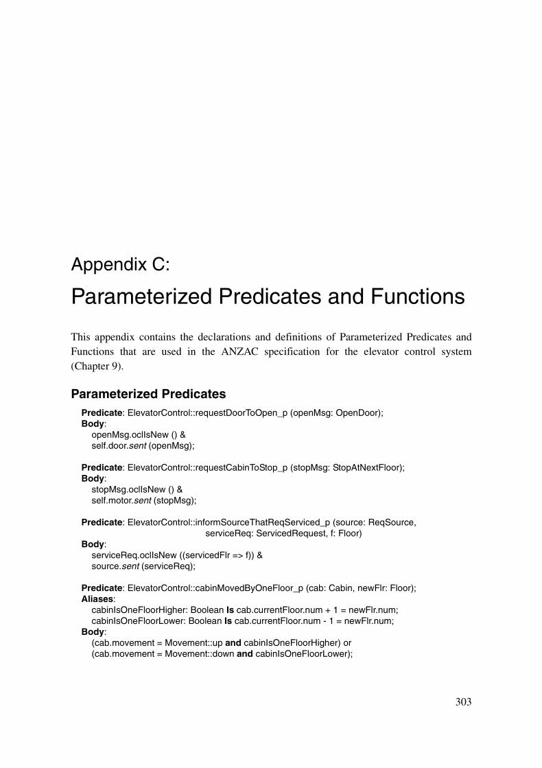
Appendix C:
Parameterized Predicates and Functions
This appendix contains the declarations and definitions of Parameterized Predicates andFunctions that are used in the ANZAC specification for the elevator control system(Chapter 9).
Parameterized PredicatesPredicate: ElevatorControl::requestDoorToOpen_p (openMsg: OpenDoor);Body:
openMsg.oclIsNew () &self.door.sent (openMsg);
Predicate: ElevatorControl::requestCabinToStop_p (stopMsg: StopAtNextFloor);Body:
stopMsg.oclIsNew () &self.motor.sent (stopMsg);
Predicate: ElevatorControl::informSourceThatReqServiced_p (source: ReqSource,serviceReq: ServicedRequest, f: Floor)
Body:serviceReq.oclIsNew ((servicedFlr => f)) &source.sent (serviceReq);
Predicate: ElevatorControl::cabinMovedByOneFloor_p (cab: Cabin, newFlr: Floor);Aliases:
cabinIsOneFloorHigher: Boolean Is cab.currentFloor.num + 1 = newFlr.num;cabinIsOneFloorLower: Boolean Is cab.currentFloor.num - 1 = newFlr.num;
Body:(cab.movement = Movement::up and cabinIsOneFloorHigher) or(cab.movement = Movement::down and cabinIsOneFloorLower);
303
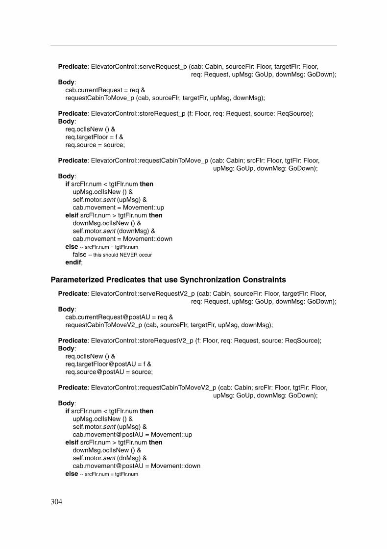
Predicate: ElevatorControl::serveRequest_p (cab: Cabin, sourceFlr: Floor, targetFlr: Floor,req: Request, upMsg: GoUp, downMsg: GoDown);
Body:cab.currentRequest = req &requestCabinToMove_p (cab, sourceFlr, targetFlr, upMsg, downMsg);
Predicate: ElevatorControl::storeRequest_p (f: Floor, req: Request, source: ReqSource);Body:
req.oclIsNew () &req.targetFloor = f &req.source = source;
Predicate: ElevatorControl::requestCabinToMove_p (cab: Cabin; srcFlr: Floor, tgtFlr: Floor,upMsg: GoUp, downMsg: GoDown);
Body:if srcFlr.num < tgtFlr.num then
upMsg.oclIsNew () &self.motor.sent (upMsg) &cab.movement = Movement::up
elsif srcFlr.num > tgtFlr.num thendownMsg.oclIsNew () &self.motor.sent (downMsg) &cab.movement = Movement::down
else -- srcFlr.num = tgtFlr.num
false -- this should NEVER occur
endif;
Parameterized Predicates that use Synchronization Constraints
Predicate: ElevatorControl::serveRequestV2_p (cab: Cabin, sourceFlr: Floor, targetFlr: Floor,req: Request, upMsg: GoUp, downMsg: GoDown);
Body:cab.currentRequest@postAU = req &requestCabinToMoveV2_p (cab, sourceFlr, targetFlr, upMsg, downMsg);
Predicate: ElevatorControl::storeRequestV2_p (f: Floor, req: Request, source: ReqSource);Body:
req.oclIsNew () &req.targetFloor@postAU = f &req.source@postAU = source;
Predicate: ElevatorControl::requestCabinToMoveV2_p (cab: Cabin; srcFlr: Floor, tgtFlr: Floor,upMsg: GoUp, downMsg: GoDown);
Body:if srcFlr.num < tgtFlr.num then
upMsg.oclIsNew () &self.motor.sent (upMsg) &cab.movement@postAU = Movement::up
elsif srcFlr.num > tgtFlr.num thendownMsg.oclIsNew () &self.motor.sent (dnMsg) &cab.movement@postAU = Movement::down
else -- srcFlr.num = tgtFlr.num
304

Parameterized Predicates and Functions
false -- this should NEVER occur
endif;
Predicate: ElevatorControl::requestCabinToMoveOrDoorToOpen_p (cab: Cabin, srcFlr: Floor,tgtFlr: Floor, upMsg: GoUp, downMsg: GoDown, openMsg: OpenDoor);
Body:if srcFlr.num = tgtFlr.num then
openMsg.oclIsNew () &self.door.sent (openMsg) &cab.doorState@postAU = DoorState::open
elserequestCabinToMoveV2_p (cab, srcFlr, tgtFlr, upMsg, downMsg)
endif;
FunctionsFunction: ElevatorControl::calcNextRequest_f (cab: Cabin): Request;-- results in the most eligable request for the cabin to serve-- (could be just the request that is already the current one)
Function: ElevatorControl::makeStopAccordingToPolicy_f (cab: Cabin,floorReached: Floor): Boolean;
-- results in true if there is a request for the floor that obeys the current stopping policy of-- the system (adding something like a “mode” attribute to the cabin object would allow-- dynamic changes to this strategy)
305

306

307
Curriculum Vitae
Shane Sendall is a New Zealand and Australian citizen.
Education
1994 - 1996 Computer science studies at the University of Queensland, Australia; gradu-ated 1996 with Bachelor of Science.
1997 Computer science studies at the University of Queensland, Australia; gradu-ated 1997 with Honours Degree (Class I) in Computer Science.
Research
1997 Binary Translation: support for semantic analysis of machine instructions;development of a Java byte-code decoder and the analysis of the Java byte-codes for suitability as an intermediate representation.
1997 Specification-Based Testing: development of translation methods for takingObject-Z specifications to C++ test oracles.
1998 - 2002 Ph.D. thesis in the field of software development methods and softwaremodeling.
Teaching
1996 Tutor for Program Verification course, given to 2nd year computer sciencestudents.
1997 Tutor for Software Specification course, given to 2nd year computer sciencestudents.
1997 Tutor for Declarative and Functional Programming course, given to 2nd yearcomputer science students.
1998 - 2002 Assistant of the Software Engineering Project for 3rd year computer sciencestudents.
2001 Two day course to private sector on “Requirements Elicitation and Analysiswith Use Cases” at Swiss Federal Institute of Technology in Lausanne.
2001 - 2002 Guest Lecturer for Software Engineering Course, given to 3rd year com-puter science students.
Other Activities
1994 Rugby Union: Member of the Queensland Country Champions.1996 Rugby Union: Captain of Souths Club 1st XV (Sunshine Coast).