speck on
TRANSCRIPT
Overview . . . . . . . . . . . . . . . . . . . . . . . . . . . . . . M2
Catalog Numbering System . . . . . . . . . . . . . . . . M2
Terminals
Features and Benefits . . . . . . . . . . . . . . . . . . . . . M3
Performance Requirements. . . . . . . . . . . . . . . . . M4
Ring Terminals . . . . . . . . . . . . . . . . . . . . . . . M5-M7
Multiple Stud Ring Terminals . . . . . . . . . . . . . M8-M9
Large Ring Terminals . . . . . . . . . . . . . . . . M10-M12
Fork Terminals . . . . . . . . . . . . . . . . . . . . . M13-M15
Locking Fork Terminals . . . . . . . . . . . . . . . M16-M17
Flanged Fork Terminals . . . . . . . . . . . . . . . M18-M19
Blade Terminals . . . . . . . . . . . . . . . . . . . . . . . . M20
Pin Terminals . . . . . . . . . . . . . . . . . . . . . . . . . . M21
Disconnects
Features and Benefits . . . . . . . . . . . . . . . . . . . . M22
Design Features . . . . . . . . . . . . . . . . . . . . . . . . M22
Performance Requirements. . . . . . . . . . . . . . . . M22
Female Disconnects . . . . . . . . . . . . . . . . . . . . 23-24
Male Disconnects . . . . . . . . . . . . . . . . . . . . . . . M25
Piggy Back Disconnects . . . . . . . . . . . . . . . . . . M26
Fully Insulated Female Disconnects . . . . . M27-M28
Fully Insulated Male Disconnects . . . . . . . . . . . M28
Insulated Female Flag Disconnects. . . . . . . . . . M29
Insulated Barrel Flag Female Disconnects. . . . . M29
Bullet Receptacles . . . . . . . . . . . . . . . . . . . . . . M30
Bullet Disconnects . . . . . . . . . . . . . . . . . . . . . . M31
Splices, Wire Joints and Quick Splices
Features and Benefits . . . . . . . . . . . . . . . . . . . . M32
Butt Splices. . . . . . . . . . . . . . . . . . . . . . . . M33-M34
Wire Joints . . . . . . . . . . . . . . . . . . . . . . . . . . . . M34
Quick Splices . . . . . . . . . . . . . . . . . . . . . . . . . . M34
Installation Tools
Hand Tools . . . . . . . . . . . . . . . . . . . . . . . . M35-M37
Automated Tools . . . . . . . . . . . . . . . . . . . . M38-M39
Power Operated Tools. . . . . . . . . . . . . . . . M40-M41
Application Information
Tool & Die Selection Chart . . . . . . . . . . . . . . . . M42
Strip Length Chart. . . . . . . . . . . . . . . . . . . . . . . M42
Stud Size Chart . . . . . . . . . . . . . . . . . . . . . . . . M43
Common Conductor Size Chart. . . . . . . . . . . . . M43
M
412031.M01 SPEC 3/5 3/14/03 10:40 AM Page 1
Overview
Crimp Terminals, Disconnects, and Splices
Catalog Numbering System
Thomas & Betts is pleased to introduce Spec-Kon® crimpterminals, disconnects, and splices. Ideal for OEM applications,the Spec-Kon® line can be used anywhere a high number of terminations are required every day, such as the wiring harness,
panelboard, telecommunications, and automotive industries.
The Spec-Kon® terminal offering includes:
• A broad selection of bulk-packaged loose piece terminals in non-insulatedand insulated varieties, including male and female disconnects, rings,forks, pins, blades, butt splices, wire joints and bullet connectors.
• Terminals on mylar tape for automated applications, including the newKT-2500 power tool for frequent, repeated crimps.
• The ERG-2500 ergonomic hand tool, which crimps all sizes of insulatedbarrel-style Spec-Kon® wire termination products.
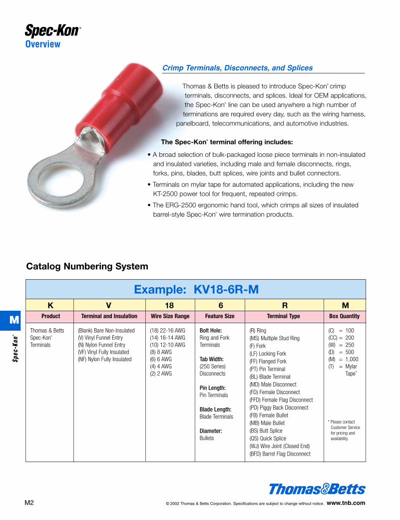
Example: KV18-6R-MK V 18 6 R M
Product Terminal and Insulation Wire Size Range Feature Size Terminal Type Box Quantity
Thomas & BettsSpec-Kon®
Terminals
(Blank) Bare Non-Insulated(V) Vinyl Funnel Entry(N) Nylon Funnel Entry(VF) Vinyl Fully Insulated(NF) Nylon Fully Insulated
(18) 22-16 AWG(14) 16-14 AWG(10) 12-10 AWG(8) 8 AWG(6) 6 AWG(4) 4 AWG(2) 2 AWG
Bolt Hole:Ring and Fork Terminals
Tab Width:(250 Series) Disconnects
Pin Length:Pin Terminals
Blade Length:Blade Terminals
Diameter:Bullets
(R) Ring(MS) Multiple Stud Ring(F) Fork(LF) Locking Fork(FF) Flanged Fork(PT) Pin Terminal(BL) Blade Terminal(MD) Male Disconnect(FD) Female Disconnect(FFD) Female Flag Disconnect(PD) Piggy Back Disconnect(FB) Female Bullet(MB) Male Bullet(BS) Butt Splice(QS) Quick Splice(WJ) Wire Joint (Closed End)(BFD) Barrel Flag Disconnect
(C) = 100(CC) = 200(W) = 250(D) = 500(M) = 1,000(T) = Mylar
Tape*
* Please contact Customer Servicefor pricing and availability.
M2 © 2002 Thomas & Betts Corporation. Specifications are subject to change without notice. www.tnb.com
M
Spec
-Kon
®
412031.M01 SPEC 3/5 3/14/03 10:40 AM Page 2
Terminals
Features and Benefits of Spec-Kon® Terminals
• Internal barrel serrations—During crimping, the wire will cold flow into serrations, giving lower resistance connections and improving tensile strength.
• Size marking—Wire range is stamped on the tongue (metric and English) foreasy access to the terminal size without drawings/packaging.
• Electro tin plating—Provides excellent corrosion resistance, superior finish forbetter-looking installation.
• Ergonomic hand tool—Ergonomically designed ERG-2500 completes a ULlisted crimp while requiring substantially lower handle forces.
• One tool for all insulated products—Thomas & Betts offers a single tool thatcrimps the entire range of standard insulated terminals, disconnects, and buttsplices. Many competitors require 2 to 4 tools to cover the same range.
• Color coding—Insulators are color coded for specific wire size (red=22-16AWG, blue=16-14AWG, yellow=12-10AWG). Red=8AWG,blue=6AWG.
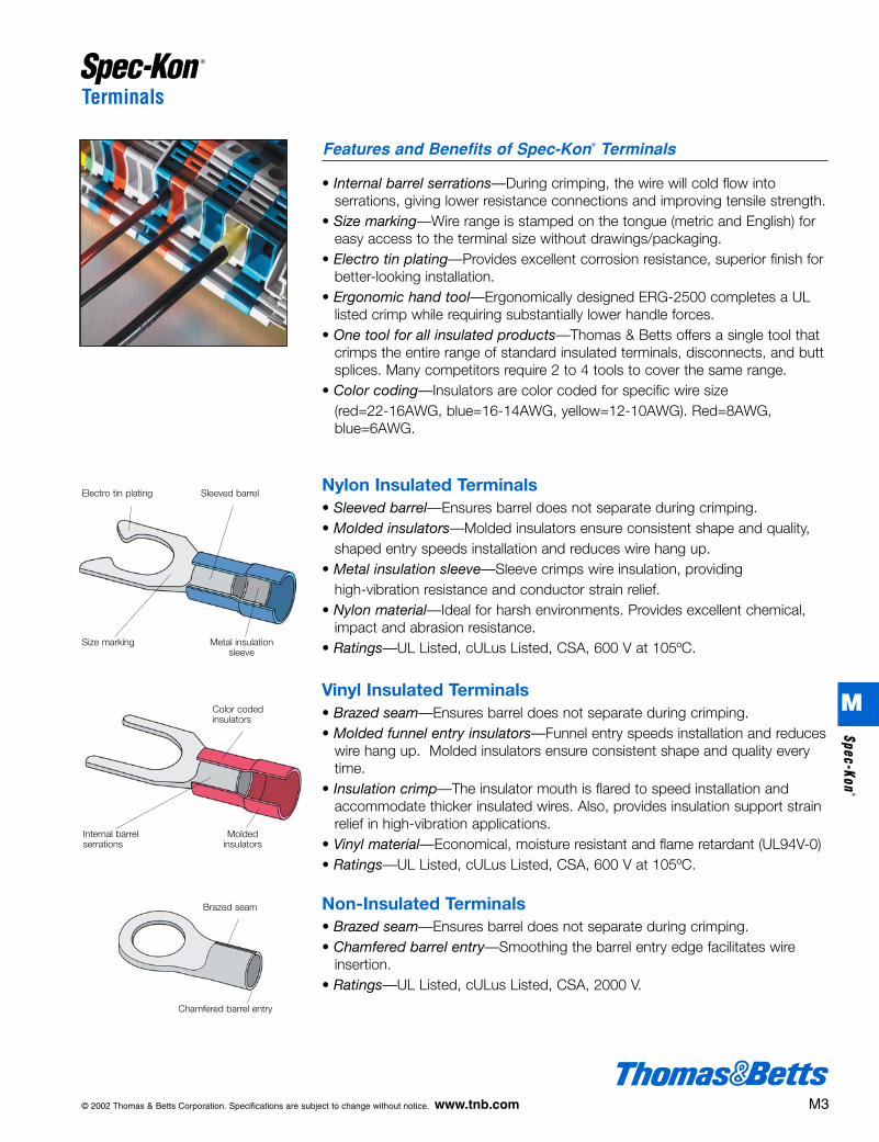
Nylon Insulated Terminals• Sleeved barrel—Ensures barrel does not separate during crimping.• Molded insulators—Molded insulators ensure consistent shape and quality,
shaped entry speeds installation and reduces wire hang up.• Metal insulation sleeve—Sleeve crimps wire insulation, providing
high-vibration resistance and conductor strain relief.• Nylon material—Ideal for harsh environments. Provides excellent chemical,
impact and abrasion resistance.• Ratings—UL Listed, cULus Listed, CSA, 600 V at 105ºC.
Vinyl Insulated Terminals• Brazed seam—Ensures barrel does not separate during crimping. • Molded funnel entry insulators—Funnel entry speeds installation and reduces
wire hang up. Molded insulators ensure consistent shape and quality everytime.
• Insulation crimp—The insulator mouth is flared to speed installation andaccommodate thicker insulated wires. Also, provides insulation support strainrelief in high-vibration applications.
• Vinyl material—Economical, moisture resistant and flame retardant (UL94V-0)• Ratings—UL Listed, cULus Listed, CSA, 600 V at 105ºC.
Non-Insulated Terminals• Brazed seam—Ensures barrel does not separate during crimping. • Chamfered barrel entry—Smoothing the barrel entry edge facilitates wire
insertion.• Ratings—UL Listed, cULus Listed, CSA, 2000 V.
Electro tin plating Sleeved barrel
Size marking Metal insulationsleeve
Color coded insulators
Internal barrel serrations
Moldedinsulators
Brazed seam
Chamfered barrel entry
© 2002 Thomas & Betts Corporation. Specifications are subject to change without notice. www.tnb.com M3
M
Spec-Kon®
412031.M01 SPEC 3/5 3/14/03 10:40 AM Page 3

Terminals
PinsStandard insulation-styleterminals for use on DIN-style/metric terminal blocks
BladesStandard insulation-styleterminals for use on DIN-style/metric terminal blocks
RingsProvides the most secure andreliable connection available
Multiple-Stud RingsSpecial tongue style thataccommodates 3 stud sizeswith one terminal
ForksFast and easy to install withoutremoving the terminal blockscrew
Locking ForksOffers the secure connection of a ring terminal with the fast andeasy installation of a fork terminal
Flanged ForksTurned-up toes provide secureconnections in high-vibrationapplications
Design Features of Spec-Kon® Terminals
Performance Requirements
Description
U.L. 486A (Terminals)
Test Current for Max. 50˚C Rise (Amps)
Min. Tensile Strength* (Lbs.)
9 12 17 18 30 35 50 70 95 125 70
8 13 20 30 50 70 80 90 100 140 180
#22 #20 #18 #16 #14 #12 #10 #8 #6 #4 #2
Wire Size (AWG)
Applicable Spec-Kon® products meet or exceed the following test specifications:• UL486A (Terminals)
• CSA
• UL486C (Splices)
UL listed products are shown with the applicable logos in the product section.
UL file #E9809 (Terminals).
CSA file #LR4503
* Pull-out force of the crimped terminal.
M4 © 2002 Thomas & Betts Corporation. Specifications are subject to change without notice. www.tnb.com
M
Spec
-Kon
®
412031.M01 SPEC 3/5 3/14/03 10:40 AM Page 4

Terminals
KN18-6R-M #6.146 .260 .248 .8033.7 6.6 6.3 20.4
KN18-8R-M #8.169 .260 .248 .8034.3 6.6 6.3 20.4
KN18-10R-M #10.209 .315 .276 .8585.3 8.0 7.0 21.8
KN18-14R-M 1/4.252 .457 .433 1.0946.4 11.6 11.0 27.8
KN18-516R-M 5/16.331 .457 .433 1.0948.4 11.6 11.0 27.8
KN14-6R-M #6.146 .260 .248 .8.33.7 6.6 6.3 20.4
Nylon Insulated Ring TerminalsCatalog Wire Bolt Dimension Number Range Size (d2) W F L E D d1 T
22-16A.W.G.
0.5-1.5mm2
16-14A.W.G.
1.5-2.5mm2
12-10A.W.G.
4-6mm2
inchmm
.433 .177 .067 .03011.0 4.5 1.7 0.75
.433 .205 .091 .03111.0 5.2 2.3 0.8
.512 .276 .134 .03913.0 7.0 3.4 1.0
KN14-8R-M #8.169 .260 .248 .8034.3 6.6 6.3 20.4
KN14-10R-M #10.209 .335 .307 .8985.3 8.5 7.8 22.8
KN14-14R-M 1/4.252 .472 .433 1.0946.4 12.0 11.0 27.8
KN14-516R-M 5/16.331 .472 .433 1.0948.4 12.0 11.0 27.8
KN14-38R-M 3/8.413 .535 .547 1.24010.5 13.6 13.9 31.5
KN10-6R-D #6.146 .283 .240 .8943.7 7.2 6.1 22.7
KN10-8R-D #8.169 .283 .240 .8944.3 7.2 6.1 22.7
KN10-10R-D #10.209 .374 .358 1.0475.3 9.5 9.1 26.6
KN10-14R-D 1/4.252 .472 .413 1.1646.4 12.0 10.5 29.5
KN10-516R-D 5/16.331 .591 .531 1.3398.4 15.0 13.5 34.0
KN10-38R-D 3/8.413 .591 .531 1.33910.5 15.0 13.5 34.0
KN10-12R-D 1/2.512 .756 .630 1.52013.0 19.2 16.0 38.6
Box Quantity: (D)=500; (M)=1000For Mylar Tape replace box quantity with (T). Example: KN18-6R-TUL File #E9809CSA File #LR4503
See pages in back of catalog for complete tool information.Tool and Die Selection Chart on page M42.
Maximum Electrical Rating: 105˚C 600 Volts Max.Terminal Material: Copper
• Metal Insulation Sleeve
• Molded Insulator
• Internal Barrel Serrations
• Funnel Entry
®
®
© 2002 Thomas & Betts Corporation. Specifications are subject to change without notice. www.tnb.com M5
For complete information regarding tools and the new Universal Applicator, see pages M35-M41.
ERG2500
Tools used with Nylon Insulated Ring Terminals
KT-2500
M
Spec-Kon®
412031.M01 SPEC 3/5 3/14/03 10:40 AM Page 5

Catalog Wire Bolt Dimension Number Range Size (d2)
22-16A.W.G.
0.5-1.5mm2
16-14A.W.G.
1.5-2.5mm2
12-10A.W.G.
4-6mm2
KV18-6R-M #6.146 .260 .248 .8033.7 6.6 6.3 20.4
KV18-8R-M #8.169 .260 .248 .8034.3 6.6 6.3 20.4
KV18-10R-M #10.209 .315 .276 .8585.3 8.0 7.0 21.8
KV18-14R-M 1/4.252 .457 .433 1.0946.4 11.6 11.0 27.8
KV18-516R-M 5/16 .331 .457 .433 1.0948.4 11.6 11.0 27.8
KV18-38R-M 3/8 .413 .835 .547 1.24010.5 13.6 13.9 31.5
KV14-6R-M #6.146 .260 .248 .8033.7 6.6 6.3 20.4
KV14-8R-M#8
.169 .260 .248 .8034.3 6.6 6.3 20.4
KV14-10R-M#10
.209 .335 .307 .8985.3 8.5 7.8 22.8
KV14-14R-M1/4
.252 .472 .433 1.0946.4 12.0 11.0 27.8
KV14-516R-M 5/16.331 .472 .433 1.0948.4 12.0 11.0 27.8
KV14-38R-M 3/8.413 .535 .547 1.24010.5 13.6 13.9 31.5
KV10-6R-D #6.146 .283 .240 .8943.7 7.2 6.1 22.7
KV10-8R-D #8.169 .283 .240 .8944.3 7.2 6.1 22.7
KV10-10R-D #10 .209 .374 .358 1.0475.3 9.5 9.1 26.6
KV10-14R-D 1/4 .252 .472 .413 1.1616.4 12.0 10.5 29.5
KV10-516R-D 5/16 .331 .591 .531 1.3398.4 15.0 13.5 34.0
KV10-38R-D 3/8 .413 .591 .531 1.33910.5 15.0 13.5 34.0
KV10-12R-D 1/2.512 .756 .630 1.52013.0 19.2 16.0 38.6
.433 .157 .067 .03011.0 4.0 1.7 0.75
.433 .177 .091 .03111.0 4.5 2.3 0.8
.512 .252 .134 .03913.0 6.4 3.4 1.0
Terminals
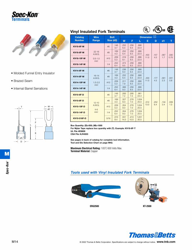
• Molded Funnel Entry Insulator
• Brazed Seam
• Internal Barrel Serrations
Vinyl Insulated Ring Terminals
W F L E D d1 T
inchmm
Box Quantity: (D)=500; (M)=1000For Mylar Tape replace box quantity with (T). Example: KV18-6R-TUL File #E9809CSA File #LR4503
See pages in back of catalog for complete tool information.Tool and Die Selection Chart on page M42.
Maximum Electrical Rating: 105˚C 600 Volts Max.Terminal Material: Copper
®
®
M6 © 2002 Thomas & Betts Corporation. Specifications are subject to change without notice. www.tnb.com
ERG2500
Tools used with Vinyl Insulated Ring Terminals
KT-2500
M
Spec
-Kon
®
412031.M01 SPEC 3/5 3/14/03 10:40 AM Page 6

Terminals
K18-6R-M #6.146 .260 .248 .5673.7 6.6 6.3 14.4
K18-8R-M #8.169 .260 .248 .5674.3 6.6 6.3 14.4
K18-10R-M #10.209 .315 .276 .6225.3 8.0 7.0 15.8
K18-14R-M 1/4.252 .457 .433 .8586.4 11.6 11.0 21.8
K18-516R-M 5/16.331 .457 .433 .8588.4 11.6 11.0 21.8
K14-6R-M #6.146 .260 .248 .5673.7 6.6 6.3 14.4
Non-Insulated Ring TerminalsCatalog Wire Bolt Dimension Number Range Size (d2) W F L E D d1 T
22-16A.W.G.
0.5-1.5mm2
16-14A.W.G.
1.5-2.5mm2
12-10A.W.G.
4-6mm2
inchmm
.189 .134 .067 .0304.8 3.4 1.7 0.75
.189 .161 .091 .0314.8 4.1 2.3 0.8
.236 .220 .134 .0396.0 5.6 3.4 1.0
K14-8R-M #8.169 .260 .248 .5674.3 6.6 6.3 14.4
K14-10R-M #10.209 .335 .307 .6615.3 8.5 7.8 16.8
K14-14R-M 1/4.252 .472 .433 .8586.4 12.0 11.0 21.8
K14-516R-M 5/16.331 .472 .433 .8588.4 12.0 11.0 21.8
K14-38R-M 3/8.413 .535 .547 1.00410.5 13.6 13.9 25.5
K10-6R-M #6.146 .283 .240 .6183.7 7.2 6.1 15.7
K10-8R-M #8.169 .283 .240 .6184.3 7.2 6.1 15.7
K10-10R-M #10.209 .374 .358 .7725.3 9.5 9.1 19.6
K10-14R-M 1/4.252 .472 .413 .8866.4 12.0 10.5 22.5
K10-516R-M 5/16.331 .591 .531 1.0638.4 15.0 13.5 27.0
K10-38R-M 3/8.413 .591 .531 1.06310.5 15.0 13.5 27.0
K10-12R-D 1/2.512 .756 .630 1.24413.0 19.2 16.0 31.6
Box Quantity: (D)=500; (M)=1000For Mylar Tape replace box quantity with (T). Example: K18-6R-TUL File #E9809CSA File #LR4503
See pages in back of catalog for complete tool information.Tool and Die Selection Chart on page M42.
Terminal Material: Copper
• Chamfered Barrel
• Brazed Seam
• Internal Barrel Serrations
®
®
© 2002 Thomas & Betts Corporation. Specifications are subject to change without notice. www.tnb.com M7
ERG2002
Tools used with Non-Insulated Ring Terminals
KT-2500
M
Spec-Kon®
412031.M01 SPEC 3/5 3/14/03 10:40 AM Page 7

Terminals
Nylon Insulated Multiple Stud Ring TerminalsCatalog Wire Bolt DimensionNumber Range Size
KN18-610MS-M #6 - #10
KN14-610MS-M #6 - #10
KN10-610MS-D #6 - #10
.339 .311 .996 .433 .177 .067 .0308.6 7.9 25.3 11.0 4.5 1.7 0.75
.339 .311 .996 .433 .205 .091 .0318.6 7.9 25.3 11.0 5.2 2.3 0.8
.390 .350 1.154 .512 .276 .134 .0399.9 8.9 29.3 13.0 7.0 3.4 1.0
inchmm
W F L E D d1 T
Box Quantity: (D)=500; (M)=1000For Mylar Tape replace box quantity with (T). Example: KN18-610MS-TUL File #E9809CSA File #LR4503
See pages in back of catalog for complete tool information.Tool and Die Selection Chart on page M42.
Maximum Electrical Rating: 105˚C 600 Volts Max.Terminal Material: Copper
Box Quantity: (D)=500; (M)=1000For Mylar Tape replace box quantity with (T). Example: KV18-610MS-TUL File #E9809CSA File #LR4503
See pages in back of catalog for complete tool information.Tool and Die Selection Chart on page M42.
Maximum Electrical Rating: 105˚C 600 Volts Max.Terminal Material: Copper
• Single terminal for 6, 8, and 10 stud sizes
• Molded Insulator
• Metal Insulation Sleeve
• Funnel Entry
• Single terminal for 6, 8, and 10 stud sizes
• Molded Funnel Entry Insulator
• Brazed Seam
22-16 A.W.G.0.5-1.5 mm2
16-14 A.W.G.1.5-2.5 mm2
12-10 A.W.G.4-6 mm2
Vinyl Insulated Multiple Stud Ring TerminalsCatalog Wire Bolt DimensionNumber Range Size
KV18-610MS-M #6 - #10
KV14-610MS-M #6 - #10
KV10-610MS-D #6 - #10
inchmm
W F L E D d1 T22-16 A.W.G.0.5-1.5 mm2
16-14 A.W.G.1.5-2.5 mm2
12-10 A.W.G.4-6 mm2
.339 .311 .996 .433 .157 .067 .0308.6 7.9 25.3 11.0 4.0 1.7 0.75
.339 .311 .996 .433 .177 .091 .0318.6 7.9 25.3 11.0 4.5 2.3 0.8
.390 .350 1.154 .512 .252 .134 .0399.9 8.9 29.3 13.0 6.4 3.4 1.0
®
®
®
®
M8 © 2002 Thomas & Betts Corporation. Specifications are subject to change without notice. www.tnb.com
ERG2500
Tools used with Nylon and Vinyl Insulated Multiple Stud Ring Terminals
KT-2500
M
Spec
-Kon
®
412031.M01 SPEC 3/5 3/14/03 10:40 AM Page 8

Terminals
Box Quantity: (M)=1000For Mylar Tape replace box quantity with (T). Example: K18-610MS-TUL File #E9809CSA File #LR4503
Terminal Material: Copper
See pages in back of catalog for complete tool information.Tool and Die Selection Chart on page M42.
• Single terminal for 6, 8, and 10 stud sizes
• Brazed Seam
• Chamfered Barrel
• Internal Barrel Serrations
Non-Insulated Multiple Stud Ring TerminalsCatalog Wire Bolt DimensionNumber Range Size
K18-610MS-M #6 - #10
K14-610MS-M #6 - #10
K10-610MS-M #6 - #10
inchmm
W F L E D d1 T22-16 A.W.G.0.5-1.5 mm2
16-14 A.W.G.1.5-2.5 mm2
12-10 A.W.G.4-6 mm2
.339 .311 .768 .189 .134 .067 .0308.6 7.9 19.5 4.8 3.4 1.7 0.75
.339 .311 .768 .189 .161 .091 .0318.6 7.9 19.5 4.8 4.1 2.3 0.8
.390 .350 .886 .236 .220 .134 .0399.9 8.9 22.5 6.0 5.6 3.4 1.0
®
®
© 2002 Thomas & Betts Corporation. Specifications are subject to change without notice. www.tnb.com M9
ERG2002
Tools used with Non-Insulated Multiple Stud Ring Terminals
KT-2500
M
Spec-Kon®
412031.M01 SPEC 3/5 3/14/03 10:41 AM Page 9

Terminals
Nylon Insulated Large Ring TerminalsCatalog Wire Bolt DimensionNumber Range Size (d2)
KN8-8R-D #8.169 .315 .366 1.1424.3 8.0 9.3 29.0
KN8-10R-D #10.209 .364 .429 1.2325.3 8.8 10.9 31.3
KN8-14R-D 1/4.252 .472 .366 1.2326.4 12.0 9.3 31.3
KN8-516R-D 5/16.331 .591 .543 1.4698.4 15.0 13.8 37.3
KN8-38R-D 3/8.413 .591 .543 1.46910.5 15.0 13.8 37.3
KN8-12R-D 1/2.512 .787 .591 1.61413.0 20.0 15.0 41.0
KN6-10R-W #10.2095.3
KN6-14R-W 1/4.2526.4
KN6-516R-W 5/16.3318.4
KN6-38R-W 3/8.41310.5
KN6-12R-W 1/2.512 .866 .780 2.04713.0 22.0 19.8 52.0
inchmm
8A.W.G.
8mm2
6A.W.G.
14mm2
.472 .524 1.60612.0 13.3 40.8
.630 .315 .177 .04716.0 8.0 4.5 1.2
.846 .433 .228 .05921.5 11.0 5.8 1.5.630 .559 1.713
16.0 14.2 43.5
W F L E D d1 T
Box Quantity: (W)=250; (D)=500For mylar tape, replace box quantity with (T). Example: KN8-8R-T.
See pages in back of catalog for complete tool information.Tool and Die Selection Chart on page M42.
Maximum Electrical Rating: 105˚C 600 Volts Max.Terminal Material: Copper
#8 AWG on mylar tape is UL Listed.#6 AWG on mylar tape is UL Listed.
UL File #E9809CSA File #LR4503
• Brazed Seam
• Molded Funnel Entry Insulator
• Internal Barrel Serrations
TBM6S
For tooling information for nylon insulatedlarge ring terminals, see page M37.
®
M10 © 2002 Thomas & Betts Corporation. Specifications are subject to change without notice. www.tnb.com
Tools used with Nylon Insulated Large Ring Terminals
KT-2500
M
Spec
-Kon
®
412031.M01 SPEC 3/5 3/14/03 10:41 AM Page 10

Terminals
K8-516R-D 5/16.331 .591 .543 1.1618.4 15.0 13.8 29.8
K8-38R-D 3/8.413 .591 .543 1.16110.5 15.0 13.8 29.8
K8-12R-D 1/2.512 .787 .591 1.31913.0 20.0 15.0 33.5
Non-Insulated Large Ring TerminalsCatalog Wire Bolt Dimension Number Range Size (d2) W F L E D d1 T
inchmm
K6-10R-D #10.209 .472 .524 1.1735.3 12.0 13.3 29.8
K6-14R-D 1/4.252 .472 .524 1.1736.4 12.0 13.3 29.8
K6-516R-D 5/16.331 .630 .559 1.2808.4 16.0 14.2 32.5
K6-38R-D 3/8.413 .630 .559 1.28010.5 16.0 14.2 32.5
K6-12R-W 1/2.512 .866 .780 1.61413.0 22.0 19.8 41.0
.337 .283 .177 .0478.5 7.2 4.5 1.2
.413 .354 .228 .05910.5 9.0 5.85 1.5
6A.W.G.
14mm2
8A.W.G.
8mm2
K8-8R-D #8.169 .315 .366 .8464.3 8.0 9.3 21.5
K8-10R-D #10.209 .346 .429 .9375.3 8.8 10.5 23.8
K8-14R-D 1/4.252 .472 .366 .9376.4 12.0 9.3 23.8
Box Quantity: C=100; CC=200; (W)=250;(D)=500;
For mylar tape, replace box quantity with(T). Example: K6-10R-T.See pages in back of catalog for completetool information.Tool and Die Selection Chart on page M42.
Terminal Material: Copper
UL File #E9809*Pending UL Listing
• Brazed Seam
• Chamfered Barrel
• Internal Barrel Serrations
®
© 2002 Thomas & Betts Corporation. Specifications are subject to change without notice. www.tnb.com M11
K4-8R-W* #8.169 .481 .594 1.3074.3 12.2 15.1 33.2
K4-10R-W* #10.209 .481 .594 .1.3075.3 12.2 15.1 33.2
K4-14R-W* 1/4.252 .481 .594 1.2996.4 12.2 15.1 33.0
K4-516R-W* 5/16.331 .650 .531 1.3198.4 16.5 13.5 33.5
K4-38R-W* 3/8.413 .650 .531 1.31910.5 16.5 13.5 33.5
K4-12R-CC* 1/2.512 .866 .776 1.66113.0 22.0 19.7 42.5
K2-10R-CC* #10.209 .602 .685 1.5355.3 15.3 17.4 39.0
K2-14R-CC* 1/4.252 .602 .685 1.5356.4 15.3 17.4 39.0
K2-516R-CC* 5/16.331 .602 .685 1.535 .551 .524 .370 .0718.4 15.3 17.4 39.0 14.0 13.3 9.4 1.8
K2-38R-CC* 3/8.413 .602 .685 1.53510.5 15.3 17.4 39.0
K2-12R-CC* 1/2.512 .866 .697 1.68113.0 22.0 17.7 42.7
.472 .453 .303 .06712.0 11.5 7.7 1.7
4A.W.G.
22mm2
2A.W.G.
38mm2
TBM6S
For tooling information for nylon insulated large ringterminals, see page M37.
Tools used with Non-InsulatedLarge Ring Terminals
KT-2500
M
Spec-Kon®
412031.M01 SPEC 3/5 3/14/03 10:41 AM Page 11

K8-516R-D 5/16.331 .591 .543 1.498.4 15.0 13.8 37.8
KV8-38R-D 3/8.413 .591 .543 1.4910.5 15.0 13.8 37.8
KV8-12R-D 1/2.512 .787 .591 1.6313.0 20.0 15.0 41.5
Vinyl Insulated Large Ring TerminalsCatalog Wire Bolt Dimension Number Range Size (d2) W F L E D d1 T
inchmm
KV6-10R-W #10.209 .472 .524 1.625.3 12.0 13.3 41.2
KV6-14R-W 1/4.252 .472 .524 1.626.4 12.0 13.3 41.2
KV6-516R-W 5/16.331 .630 .571 1.758.4 16.0 14.5 44.5
KV6-38R-W 3/8.413 .630 .571 1.7510.5 16.0 14.5 44.5
KV6-12R-W 1/2.512 .866 .780 2.0913.0 22.0 19.8 53
.886 .414 .222 .05922.5 10.5 5.65 1.5
6A.W.G.
14mm2
KV8-8R-D #8.169 .315 .366 1.164.3 8.0 9.3 29.5
KV8-10R-D #10.209 .346 .429 1.255.3 8.8 10.9 31.8
KV8-14R-D 1/4.252 .472 .366 1.256.4 12.0 9.3 31.8
®
TBM6S
For tooling information for nylon insulatedlarge ring terminals, see page M37.
Tools used with Vinyl Insulated Large Ring Terminals
KT-2500
• Brazed Seam
• Internal Barrel Serrations
Box Quantity: (W)=250; (D)=500For mylar tape, replace box quantity with (T). Example: KN8-8R-T.
See pages in back of catalog for complete tool information.Tool and Die Selection Chart on page M42.
Maximum Electrical Rating: 105˚C 600 Volts Max.Terminal Material: Copper
#8 AWG on mylar tape is UL Listed.#6 AWG on mylar tape is UL Listed.
UL File #E9809CSA File #LR4503
.650 .335 .177 .04716.5 8.5 4.5 1.2
8A.W.G.
8mm2
Terminals
M12 © 2002 Thomas & Betts Corporation. Specifications are subject to change without notice. www.tnb.com
M
Spec
-Kon
®
412031.M01 SPEC 3/5 3/14/03 10:41 AM Page 12

Nylon Insulated Fork TerminalsCatalog Wire Bolt DimensionNumber Range Size (d2)
22-16A.W.G.
0.5-1.5mm2
16-14A.W.G.
1.5-2.5mm2
12-10A.W.G.
4-6mm2
KN18-6F-M #6.146 .252 .256 .8663.7 6.4 6.5 22.0
KN18-8F-M #8.169 .252 .256 .8664.3 6.4 6.5 22.0
KN18-10F-M #10.209 .319 .256 .866
.433 .177 .067 .030
5.3 8.1 6.5 22.011.0 4.5 1.7 0.75
KN18-14F-M 1/4.252 .374 .256 .8666.4 9.5 6.5 22.0
KN14-6F-M #6.146 .236 .256 .8663.7 6.0 6.5 22.0
KN14-8F-M #8.169 .252 .256 .8664.3 6.4 6.5 22.0
KN14-10F-M #10.209 .311 .256 .866
.433 .205 .091 .031
5.3 7.9 6.5 22.0
11.0 5.2 2.3 0.8
KN14-14F-M 1/4.252 .366 .256 .8666.4 9.3 6.5 22.0
KN10-6F-D #6.146 .283 .295 .9613.7 7.2 7.5 24.4
KN10-8F-D #8.169 .327 .276 1.0044.3 8.3 7.0 25.5
KN10-10F-D #10.209 .354 .276 1.004
.512 .276 .134 .039
5.3 9.0 7.0 25.5
13.0 7.0 3.4 1.0
KN10-14F-D 1/4.252 .354 .276 1.0046.4 9.0 7.0 25.5
KN10-516F-D 5/16.315 .551 .413 1.2018.4 14.0 10.5 30.5
inchmm
W F L E D d1 T
Box Quantity: (D)=500; (M)=1000For Mylar Tape replace box quantity with (T). Example: KN18-6F-TUL File #E9809CSA File #LR4503
See pages in back of catalog for complete tool information.Tool and Die Selection Chart on page M42.
Maximum Electrical Rating: 105˚C 600 Volts Max.Terminal Material: Copper
• Metal Insulation Sleeve
• Molded Insulator
• Internal Barrel Serrations
• Funnel Entry
®
®
Tools used with Nylon Insulated Ring Terminals
ERG2500 KT-2500
Terminals
© 2002 Thomas & Betts Corporation. Specifications are subject to change without notice. www.tnb.com M13
M
Spec-Kon®
412031.M01 SPEC 3/5 3/14/03 10:41 AM Page 13
Terminals
Vinyl Insulated Fork TerminalsCatalog Wire Bolt DimensionNumber Range Size (d2)
22-16A.W.G.
0.5-1.5mm2
16-14A.W.G.
1.5-2.5mm2
12-10A.W.G.
4-6mm2
KV18-6F-M #6.146 .252 .256 .8663.7 6.4 6.5 22.0
KV18-8F-M #8.169 .252 .256 .8664.3 6.4 6.5 22.0
KV18-10F-M #10.209 .319 .256 .866
.433 .157 .067 .030
5.3 8.1 6.5 22.011.0 4.0 1.7 0.75
KV18-14F-M 1/4.252 .374 .256 .8666.4 9.5 6.5 22.0
KV14-6F-M #6.146 .236 .256 .8663.7 6.0 6.5 22.0
KV14-8F-M #8.169 .252 .256 .8664.3 6.4 6.5 22.0
KV14-10F-M #10.209 .311 .256 .866
.433 .177 .091 .031
5.3 7.9 6.5 22.0
11.0 4.5 2.3 0.8
KV14-14F-M 1/4.252 .366 .256 .8666.4 9.3 6.5 22.0
KV10-6F-D #6.146 .283 .295 .9613.7 7.2 7.5 24.4
KV10-8F-D #8.169 .327 .276 1.0044.3 8.3 7.0 25.5
KV10-10F-D #10.209 .354 .276 1.004
.512 .252 .134 .039
5.3 9.0 7.0 25.5
13.0 6.4 3.4 1.0
KV10-14F-D 1/4.252 .354 .276 1.0046.4 9.0 7.0 25.5
KV10-516F-D 5/16.315 .551 .413 1.2018.4 14.0 10.5 30.5
inchmm
W F L E D d1 T
Box Quantity: (D)=500; (M)=1000For Mylar Tape replace box quantity with (T). Example: KV18-6F-TUL File #E9809CSA File #LR4503
See pages in back of catalog for complete tool information.Tool and Die Selection Chart on page M42.
Maximum Electrical Rating: 105˚C 600 Volts Max.Terminal Material: Copper
• Molded Funnel Entry Insulator
• Brazed Seam
• Internal Barrel Serrations
®
®
M14 © 2002 Thomas & Betts Corporation. Specifications are subject to change without notice. www.tnb.com
Tools used with Vinyl Insulated Fork Terminals
ERG2500 KT-2500
M
Spec
-Kon
®
412031.M01 SPEC 3/5 3/14/03 10:41 AM Page 14

© 2002 Thomas & Betts Corporation. Specifications are subject to change without notice. www.tnb.com M15
Terminals
K14-6F-M #6.146 .2363.7 6.0
K14-8F-M #8.169 .2524.3 6.4
K14-10F-M #10.209 .3195.3 8.1
Non-Insulated Fork TerminalsCatalog Wire Bolt Dimension Number Range Size (d2) W F L E D d1 T
22-16A.W.G.
0.5-1.5mm2
inchmm
K18-6F-M #6.146 .2523.7 6.4
K18-8F-M #8.169 .2524.3 6.4
K18-10F-M #10.209 .3195.3 8.1
K10-6F-M #6.146 .283 .295 .6853.7 7.2 7.5 17.4
K10-8F-M #8.169 .3274.3 8.3
K10-10F-M #10.209 .3545.3 9.0
K10-14F-M 1/4.252 .3546.4 9.0
16-14A.W.G.
1.5-2.5mm2
.256 .630 .189 .134 .067 .0306.5 16.0 4.8 3.4 1.7 0.75
.256 .630 .189 .161 .091 .0316.5 16.0 4.8 4.1 2.3 0.8
.276 .728 .236 .220 .134 .0397.0 18.5 6.0 5.6 3.4 1.0
12-10A.W.G.
4-6mm2
Box Quantity: (M)=1000For Mylar Tape replace box quantity with (T). Example: K18-6F-TUL File #E9809CSA File #LR4503
See pages in back of catalog for complete tool information.Tool and Die Selection Chart on page M42.
Terminal Material: Copper
• Chamfered Barrel
• Brazed Seam
• Internal Barrel Serrations
®
®
Tools used with Non-Insulated Fork Terminals
ERG2002 KT-2500
M
Spec-Kon®
412031.M01 SPEC 3/5 3/14/03 10:41 AM Page 15

Terminals
Nylon Insulated Locking Fork TerminalsCatalog Wire Bolt DimensionNumber Range Size (d2)
KN18-6LF-M #6.146 .2523.7 6.4
KN18-8LF-M #8.169 .2834.3 7.2
KN18-10LF-M #10.209 .3195.3 8.1
KN14-6LF-M #6.146 .2363.7 6.0
KN14-8LF-M #8.169 .2834.3 7.2
KN14-10LF-M #10.209 .3195.3 8.1
KN10-6LF-D #6.146 .3273.7 8.3
KN10-8LF-D #8.169 .3274.3 8.3
KN10-10LF-D #10.209 .3545.3 9.0
.256 .866 .433 .177 .067 .0306.5 22.0 11.0 4.5 1.7 0.75
.256 .866 .433 .205 .091 .0316.5 22.0 11.0 5.2 2.3 0.8
.276 .992 .512 .276 .134 .0397.0 25.2 13.0 7.0 3.4 1.0
inchmm
22-16A.W.G.
0.5-1.5mm2
16-14A.W.G.
1.5-2.5mm2
12-10A.W.G.
4-6mm2
W F L E D d1 T
Box Quantity: (D)=500; (M)=1000For Mylar Tape replace box quantity with (T). Example: KN18-6LF-TUL File #E9809, CSA File #LR4503
See pages in back of catalog for complete tool information.Tool and Die Selection Chart on page M42.
Maximum Electrical Rating: 105˚C 600 Volts Max.Terminal Material: Copper
• Metal Insulation Sleeve
• Molded Insulator
• Internal Barrel Serrations
• Funnel Entry
Vinyl Insulated Locking Fork TerminalsCatalog Wire Bolt DimensionNumber Range Size (d2)
KV18-6LF-M #6.146 .2523.7 6.4
KV18-8LF-M #8.169 .2834.3 7.2
KV18-10LF-M #10.209 .3195.3 8.1
KV14-6LF-M #6.146 .2363.7 6.0
KV14-8LF-M #8.169 .2834.3 7.2
KV14-10LF-M #10.209 .3195.3 8.1
KV10-6LF-D #6.146 .3273.7 8.3
KV10-8LF-D #8.169 .3274.3 8.3
KV10-10LF-D #10.209 .3545.3 9.0
.256 .866 .433 .157 .067 .0306.5 22.0 11.0 4.0 1.7 0.75
.256 .866 .433 .177 .091 .0316.5 22.0 11.0 4.5 2.3 0.8
.276 .992 .512 .252 .134 .0397.0 25.2 13.0 6.4 3.4 1.0
inchmm
22-16A.W.G.
0.5-1.5mm2
16-14A.W.G.
1.5-2.5mm2
12-10A.W.G.
4-6mm2
W F L E D d1 T
Box Quantity: (D)=500; (M)=1000For Mylar Tape replace box quantity with (T).Example: KV18-6LF-TUL File #E9809, CSA File #LR4503
See pages in back of catalog for complete toolinformation.Tool and Die Selection Chart on page M42.
Maximum Electrical Rating: 105˚C 600 Volts Max.Terminal Material: Copper
• Molded Funnel Entry Insulator
• Internal Barrel Serrations
®
®
®
®
M16 © 2002 Thomas & Betts Corporation. Specifications are subject to change without notice. www.tnb.com
ERG2500
Tools used with Nylon and VinylInsulated Locking Fork Terminals
KT-2500
M
Spec
-Kon
®
412031.M01 SPEC 3/5 3/14/03 10:41 AM Page 16
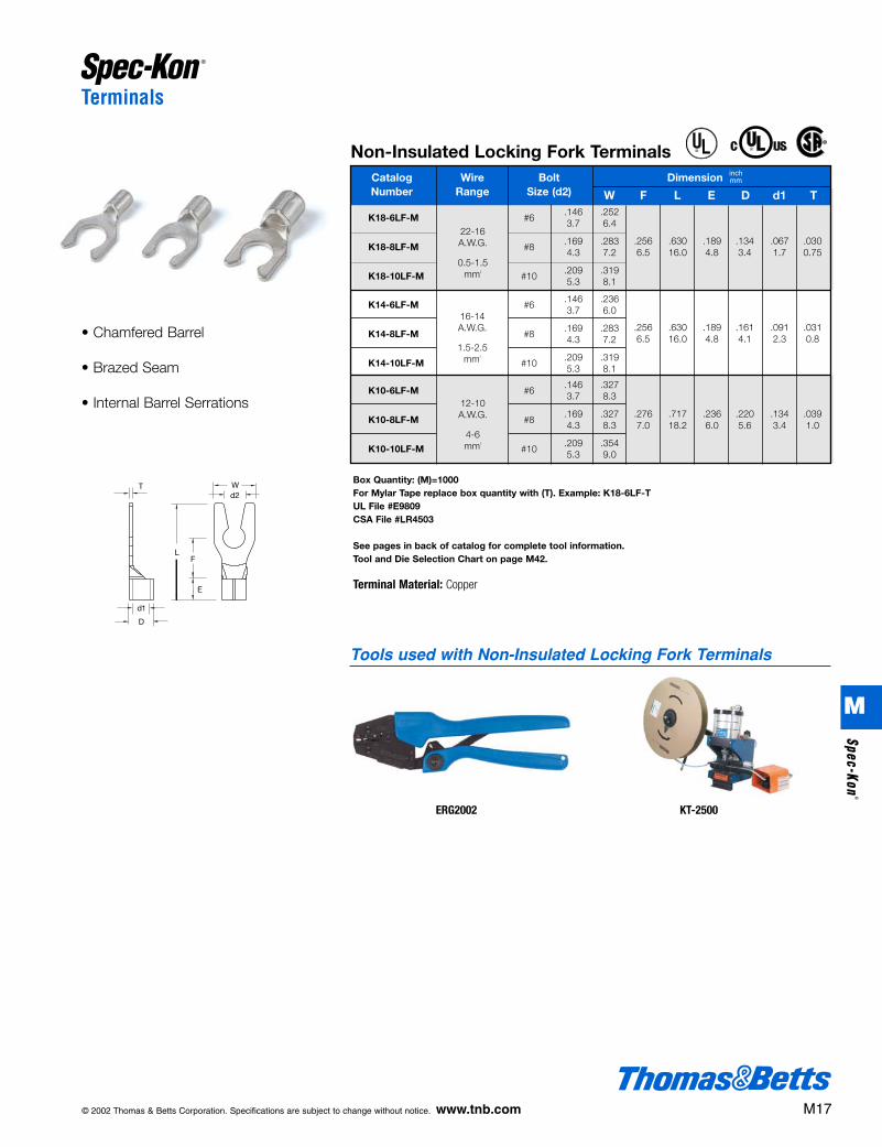
© 2002 Thomas & Betts Corporation. Specifications are subject to change without notice. www.tnb.com M17
Terminals
K14-6LF-M #6.146 .2363.7 6.0
K14-8LF-M #8.169 .2834.3 7.2
K14-10LF-M #10.209 .3195.3 8.1
Non-Insulated Locking Fork TerminalsCatalog Wire Bolt Dimension Number Range Size (d2) W F L E D d1 T
22-16A.W.G.
0.5-1.5mm2
inchmm
K18-6LF-M #6.146 .2523.7 6.4
K18-8LF-M #8.169 .2834.3 7.2
K18-10LF-M #10.209 .3195.3 8.1
K10-6LF-M #6.146 .3273.7 8.3
K10-8LF-M #8.169 .3274.3 8.3
K10-10LF-M #10.209 .3545.3 9.0
16-14A.W.G.
1.5-2.5mm2
.256 .630 .189 .134 .067 .0306.5 16.0 4.8 3.4 1.7 0.75
.256 .630 .189 .161 .091 .0316.5 16.0 4.8 4.1 2.3 0.8
.276 .717 .236 .220 .134 .0397.0 18.2 6.0 5.6 3.4 1.0
12-10A.W.G.
4-6mm2
Box Quantity: (M)=1000For Mylar Tape replace box quantity with (T). Example: K18-6LF-TUL File #E9809CSA File #LR4503
See pages in back of catalog for complete tool information.Tool and Die Selection Chart on page M42.
Terminal Material: Copper
• Chamfered Barrel
• Brazed Seam
• Internal Barrel Serrations
®
®
Tools used with Non-Insulated Locking Fork Terminals
ERG2002 KT-2500
M
Spec-Kon®
412031.M01 SPEC 3/5 3/14/03 10:41 AM Page 17

Terminals
Nylon Insulated Flanged Fork TerminalsCatalog Wire Bolt DimensionNumber Range Size (d2)
KN18-6FF-M #6.146 .335 .283 1.0043.7 8.5 7.2 25.5
KN18-8FF-M #8.169 .335 .283 1.0044.3 8.5 7.2 25.5
KN18-10FF-M #10.209 .335 .283 1.0045.3 8.5 7.2 25.5
KN14-6FF-M #6.146 .335 .283 .9453.7 8.5 7.2 24.0
KN14-8FF-M #8.169 .335 .283 .9454.3 8.5 7.2 24.0
KN14-10FF-M #10.209 .335 .283 .9455.3 8.5 7.2 24.0
KN10-6FF-D #6.146 .335 .295 1.0633.7 8.5 7.5 27.0
KN10-8FF-D #8.169 .335 .295 1.0634.3 8.5 7.5 27.0
KN10-10FF-D #10.209 .335 .295 1.0635.3 8.5 7.5 27.0
.433 .177 .067 .059 .03011.0 4.5 1.7 1.5 0.75
inchmm
22-16A.W.G.
0.5-1.5mm2
16-14A.W.G.
1.5-2.5mm2
12-10A.W.G.
4-6mm2
W F L E D d1 A T
.433 .205 .091 .059 .03111.0 5.2 2.3 1.5 0.8
.512 .276 .134 .059 .03913.0 7.0 3.4 1.5 1.0
Box Quantity: (D)=500; (M)=1000For Mylar Tape replace box quantity with (T). Example: KN18-6FF-TUL File #E9809, CSA File #LR4503
See pages in back of catalog for complete tool information.Tool and Die Selection Chart on page M42.
Maximum Electrical Rating: 105˚C 600 Volts Max.Terminal Material: Copper
• Reduces Slippage in High Vibration Applications
• Metal Insulation Sleeve
• Molded Insulator
• Internal Barrel Serrations
• Funnel Entry
Vinyl Insulated Flanged Fork TerminalsCatalog Wire Bolt DimensionNumber Range Size (d2)
KV18-6FF-M #6.146 .252 .201 .7873.7 6.4 5.1 20.0
KV18-8FF-M #8.169 .335 .283 1.0044.3 8.5 7.2 25.5
KV18-10FF-M #10.209 .335 .283 1.0045.3 8.5 7.2 25.5
KV14-6FF-M #6.146 .335 .283 .9453.7 8.5 7.2 24.0
KV14-8FF-M #8.169 .335 .283 .9454.3 8.5 7.2 24.0
KV14-10FF-M #10.209 .335 .283 .9455.3 8.5 7.2 24.0
KV10-6FF-D #6.146 .299 .244 1.0043.7 7.6 6.2 25.5
KV10-8FF-D #8.169 .299 .244 1.0044.3 7.6 6.2 25.5
KV10-10FF-D #10.209 .299 .244 1.0045.3 7.6 6.2 25.5
.433 .157 .067 .059 .03011.0 4.0 1.7 1.5 0.75
inchmm
22-16A.W.G.
0.5-1.5mm2
16-14A.W.G.
1.5-2.5mm2
12-10A.W.G.
4-6mm2
W F L E D d1 A T
.433 .177 .091 .059 .03111.0 4.5 2.3 1.5 0.8
.512 .252 .134 .059 .03913.0 6.4 3.4 1.5 1.0
Box Quantity: (D)=500; (M)=1000For Mylar Tape replace box quantity with (T).Example: KV18-6FF-TUL File #E9809, CSA File #LR4503
See pages in back of catalog for complete toolinformation.Tool and Die Selection Chart on page M42.
Maximum Electrical Rating: 105˚C 600 Volts Max.Terminal Material: Copper
• Reduces Slippage in High Vibration Applications
• Molded Funnel Entry Insulator
• Brazed Seam
• Internal Barrel Serrations
®
®
®
®
M18 © 2002 Thomas & Betts Corporation. Specifications are subject to change without notice. www.tnb.com
ERG2500
Tools used with Nylon and VinylInsulated Flanged Fork Terminals
KT-2500
M
Spec
-Kon
®
412031.M01 SPEC 3/5 3/14/03 10:41 AM Page 18

© 2002 Thomas & Betts Corporation. Specifications are subject to change without notice. www.tnb.com M19
Terminals
Box Quantity: (M)=1000For Mylar Tape replace box quantity with (T). Example: K18-6FF-TUL FIle #E9809CSA File #LR4503
See pages in back of catalog for complete tool information.Tool and Die Selection Chart on page M42.
Terminal Material: Copper
• Reduces Slippage in High Vibration Applications
• Chamfered Barrel
• Brazed Seam
• Internal Barrel Serrations
Non-Insulated Flanged Fork TerminalsCatalog Wire Bolt DimensionNumber Range Size (d2)
K18-6FF-M #6.146 .335 .283 .7683.7 8.5 7.2 19.5
K18-8FF-M #8.169 .335 .283 .7684.3 8.5 7.2 19.5
K18-10FF-M #10.209 .335 .283 .7685.3 8.5 7.2 19.5
K14-6FF-M #6.146 .335 .283 .7093.7 8.5 7.2 18.0
K14-8FF-M #8.169 .335 .283 .7094.3 8.5 7.2 18.0
K14-10FF-M #10.209 .335 .283 .7095.3 8.5 7.2 18.0
K10-6FF-M #6.146 .335 .295 .7873.7 8.5 7.5 20.0
K10-8FF-M #8.169 .335 .295 .7874.3 8.5 7.5 20.0
K10-10FF-M #10.209 .335 .295 .7875.3 8.5 7.5 20.0
.189 .134 .067 .059 .0304.8 3.4 1.7 1.5 0.75
inchmm
22-16A.W.G.
0.5-1.5mm2
16-14A.W.G.
1.5-2.5mm2
12-10A.W.G.
4-6mm2
W F L E D d1 A T
.189 .161 .091 .059 .0314.8 4.1 2.3 1.5 0.8
.236 .220 .134 .059 .0396.0 5.6 3.4 1.5 1.0
®
®
Tools used with Non-Insulated Flanged Fork Terminals
ERG2002 KT-2500
M
Spec-Kon®
412031.M01 SPEC 3/5 3/14/03 10:41 AM Page 19

Terminals
Nylon Insulated Blade TerminalsCatalog Wire DimensionNumber Range
KN18-10BL-M.091 .394 .8192.3 10.0 20.8
KN18-18BL-M.087 .709 1.1342.2 18.0 28.8
KN14-10BL-M.094 .394 .8192.4 10.0 20.8
KN14-18BL-M.087 .709 1.1342.2 18.0 28.8
KN10-10BL-D.110 .394 .906 .512 .276 .134 .0392.8 10.0 23.0
22-16 A.W.G.0.5-1.5 mm2
16-14 A.W.G.1.5-2.5 mm2
12-10 A.W.G.4-6 mm2
.433 .177 .067 .03011.0 4.5 1.7 0.75
.433 .205 .091 .03111.0 5.2 2.3 0.8
inchmm
W F L E D d1 T
Vinyl Insulated Blade TerminalsCatalog Wire DimensionNumber Range
KV18-10BL-M.091 .394 .8192.3 10.0 20.8
KV18-18BL-M.087 .709 1.1342.2 18.0 28.8
KV14-10BL-M.094 .394 .8192.4 10.0 20.8
KV14-18BL-M.087 .709 1.1342.2 18.0 28.8
KV10-10BL-D.110 .394 .9062.8 10.0 23.0
22-16 A.W.G.0.5-1.5 mm2
16-14 A.W.G.1.5-2.5 mm2
12-10 A.W.G.4-6 mm2
.433 .157 .067 .03011.0 4.0 1.7 0.75
.433 .177 .091 .03111.0 4.5 2.3 0.8
.512 .252 .134 .03913.0 6.4 3.4 1.0
inchmm
W F L E D d1 T
Box Quantity: (D)=500; (M)=1000For Mylar Tape replace box quantity with (T). Example: KN18-10BL-TUL File #E9809CSA File #LR4503
See pages in back of catalog for complete tool information.Tool and Die Selection Chart on page M42.
Maximum Electrical Rating: 105˚C 600 Volts Max.Terminal Material: Copper
Box Quantity: (D)=500; (M)=1000For Mylar Tape replace box quantity with (T). Example: KV18-10BL-TUL File #E9809CSA File #LR4503
See pages in back of catalog for complete tool information.Tool and Die Selection Chart on page M42.
Maximum Electrical Rating: 105˚C 600 Volts Max.Terminal Material: Copper
• For Use in DIN-Style Blade Terminal Blocks
• Metal Insulation Sleeve
• Molded Insulator
• Internal Barrel Serrations
• Funnel Entry
• For Use in DIN-Style Blade Terminal Blocks
• Molded Funnel Entry Insulator
• Brazed Seam
• Internal Barrel Serrations
®
®
®
®
M20 © 2002 Thomas & Betts Corporation. Specifications are subject to change without notice. www.tnb.com
ERG2500
Tools used with Nylon and Vinyl Insulated Blade Terminals
KT-2500
M
Spec
-Kon
®
412031.M01 SPEC 3/5 3/14/03 10:41 AM Page 20

© 2002 Thomas & Betts Corporation. Specifications are subject to change without notice. www.tnb.com M21
Terminals
Nylon Insulated Pin TerminalsCatalog Wire DimensionNumber Range
KN18-12PT-M.075 .472 .8981.9 12.0 22.8
KN14-12PT-M.075 .472 .8981.9 12.0 22.8
KN10-14PT-D.110 .551 1.0632.8 14.0 27.0
22-16 A.W.G.0.5-1.5 mm2
16-14 A.W.G.1.5-2.5 mm2
12-10 A.W.G.4-6 mm2
.433 .177 .067 .03011.0 4.5 1.7 0.75
.433 .205 .091 .03111.0 5.2 2.3 0.8
.512 .276 .134 .03913.0 7.0 3.4 1.0
inchmm
W F L E D d1 T
Vinyl Insulated Pin TerminalsCatalog Wire Dimension Number Range
KV18-12PT-M.075 .472 .8981.9 12.0 22.8
KV14-12PT-M.075 .472 .8981.9 12.0 22.8
KV10-14PT-D.110 .551 1.0632.8 14.0 27.0
22-16 A.W.G.0.5-2.5 mm2
16-14 A.W.G.1.5-2.5 mm2
12-10 A.W.G.4-6 mm2
.433 .157 .067 .03011.0 4.0 1.7 0.75
.433 .177 .091 .03111.0 4.5 2.3 0.8
.512 .252 .134 .03913.0 6.4 3.4 1.0
inchmm
W F L E D d1 T
Box Quantity: (D)=500; (M)=1000For Mylar Tape replace box quantity with (T). Example: KN18-12PT-TUL File #E9809CSA File #LR4503
See pages in back of catalog for complete tool information.Tool and Die Selection Chart on page M42.
Maximum Electrical Rating: 105˚C 600 Volts Max.Terminal Material: Copper
Box Quantity: (D)=500; (M)=1000For Mylar Tape replace box quantity with (T). Example: KV18-12PT-TUL File #E9809CSA File #LR4503
See pages in back of catalog for complete tool information.Tool and Die Selection Chart on page M42.
Maximum Electrical Rating: 105˚C 600 Volts Max.Terminal Material: Copper
• For Use in Pin-Style Terminal Blocks
• Metal Insulation Sleeve
• Molded Insulator
• Internal Barrel Serrations
• Funnel Entry
• For Use in Pin-Style Terminal Blocks
• Molded Funnel Entry Insulator
• Brazed Seams
• Internal Barrel Serrations
®
®
®
®
ERG2500
Tools used with Nylon and Vinyl Insulated Pin Terminals
KT-2500
M
Spec-Kon®
412031.M01 SPEC 3/5 3/14/03 10:42 AM Page 21
Disconnects
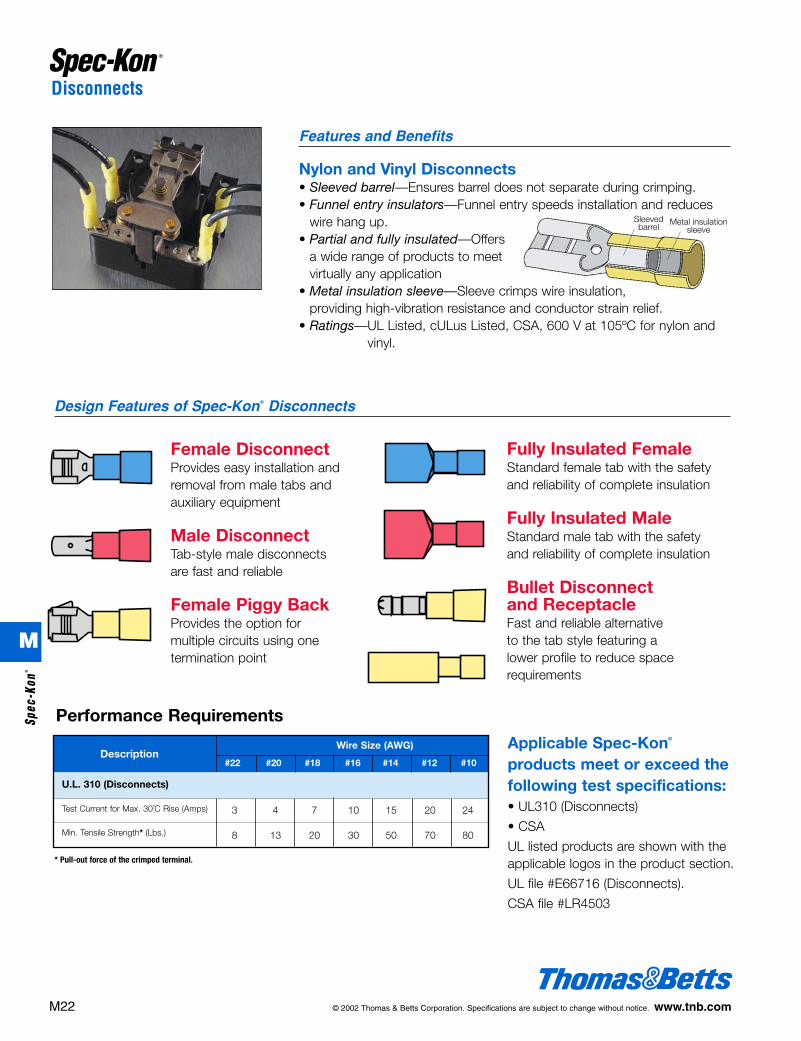
Nylon and Vinyl Disconnects• Sleeved barrel—Ensures barrel does not separate during crimping.• Funnel entry insulators—Funnel entry speeds installation and reduces
wire hang up.• Partial and fully insulated—Offers
a wide range of products to meet virtually any application
• Metal insulation sleeve—Sleeve crimps wire insulation, providing high-vibration resistance and conductor strain relief.
• Ratings—UL Listed, cULus Listed, CSA, 600 V at 105ºC for nylon andvinyl.
Features and Benefits
Female DisconnectProvides easy installation andremoval from male tabs andauxiliary equipment
Male DisconnectTab-style male disconnects are fast and reliable
Female Piggy BackProvides the option formultiple circuits using one termination point
Design Features of Spec-Kon® Disconnects
Fully Insulated FemaleStandard female tab with the safetyand reliability of complete insulation
Fully Insulated MaleStandard male tab with the safetyand reliability of complete insulation
Bullet Disconnect and ReceptacleFast and reliable alternative to the tab style featuring a lower profile to reduce space requirements
Performance Requirements
Description
U.L. 310 (Disconnects)
Test Current for Max. 30˚C Rise (Amps)
Min. Tensile Strength* (Lbs.)
3 4 7 10 15 20 24
8 13 20 30 50 70 80
#22 #20 #18 #16 #14 #12 #10
Wire Size (AWG) Applicable Spec-Kon®
products meet or exceed the following test specifications:• UL310 (Disconnects)
• CSA
UL listed products are shown with theapplicable logos in the product section.
UL file #E66716 (Disconnects).
CSA file #LR4503
* Pull-out force of the crimped terminal.
Sleevedbarrel
Metal insulation sleeve
M22 © 2002 Thomas & Betts Corporation. Specifications are subject to change without notice. www.tnb.com
M
Spec
-Kon
®
412031.M01 SPEC 3/5 3/14/03 10:42 AM Page 22

© 2002 Thomas & Betts Corporation. Specifications are subject to change without notice. www.tnb.com M23
Disconnects
Nylon Insulated Female DisconnectsCatalog Wire Tab DimensionNumber Range Size
inchmm
W F L B D T
16-14A.W.G.
1.5-2.5mm2
22-16A.W.G.
0.5-1.5mm2
12-10A.W.G.
4-6mm2
KN18-110-20FD-M .110 x .020.126 .256 .7723.2 6.5 19.6
KN18-110-32FD-M .110 x .032.126 .256 .7723.2 6.5 19.6
KN18-187-20FD-M .187 x .020.197 .252 .787 .433 .1575.0 6.4 20.0 11.0 4.0
KN18-187-32FD-M .187 x .032.197 .252 .7875.0 6.4 20.0
KN18-250FD-M .250 x .032.260 .287 .8466.6 7.3 21.5
KN14-110-20FD-M .110 x .020.126 .252 .7723.2 6.4 19.6
KN14-110-32FD-M .110 x .032.126 .252 .7723.2 6.4 19.6
KN14-187-20FD-M .187 x .020.197 .256 .787 .433 .1975.0 6.5 20.0 11.0 5.0
KN14-187-32FD-M .187 x .032.197 .256 .787 .0165.0 6.5 20.0 0.4
KN14-250FD-M .250 x .032.260 .287 .8466.6 7.3 21.5
KN10-110-20FD-D .110 x .020.126 .343 .8663.2 8.7 22.0
KN10-110-32-FD-D .110 x .032.126 .343 .8663.2 8.7 22.0
KN10-187-20FD-D .187 x .020.197 .256 .866 .512 .256 .0165.0 6.5 22.0 13.0 6.5 0.4
KN10-187-32FD-D .187 x .032.197 .256 .8665.0 6.5 22.0
KN10-250FD-D .250 x .032.260 .287 .9256.6 7.3 23.5
.0120.3
.0160.4
.0120.3
110 Tab Size
187 Tab Size
250 Tab SizeBox Quantity: (D)=500; (M)=1000For Mylar Tape replace box quantity with (T). Example: KN18-110FD-TUL File #E66716CSA File #LR4503
See pages in back of catalog for complete tool information.Tool and Die Selection Chart on page M42.
Maximum Electrical Rating: 105˚C 600 Volts Max.Terminal Material: Brass with Copper Sleeve
• For Use in Temporary
Connections to Male Disconnects
& Terminal Blocks
• Multiple Sizes for Range
of Applications
• Metal Insulation Sleeve
• Molded Insulator
• Internal Barrel Serrations
• Funnel Entry
inch
®
®
ERG2500
Tools used with Nylon Insulated Female Disconnects
KT-2500
M
Spec-Kon®
412031.M01 SPEC 3/5 3/14/03 10:42 AM Page 23

Disconnects
Vinyl Insulated Female DisconnectsCatalog Wire Tab DimensionNumber Range Size
inchmm
W F L B D T
16-14A.W.G.
1.5-2.5mm2
22-16A.W.G.
0.5-1.5mm2
12-10A.W.G.
4-6mm2
.0120.3
.0120.3
110 Tab Size
187 Tab Size
250 Tab Size
Box Quantity: (D)=500; (M)=1000For Mylar Tape replace box quantity with (T). Example: KV18-110FD-TUL FIle #E66716CSA FIle #LR4503
See pages in back of catalog for complete tool information.Tool and Die Selection Chart on page M42.
Maximum Electrical Rating: 105˚C 300 Volts Max.Terminal Material: Brass with Copper Sleeve
• For Use in Temporary
Connections to Male
Disconnects & Terminal Blocks
• Metal Insulation Sleeve
• Easy Entry Copper Sleeve
KV18-110-20FD-M .110 x .020.126 .256 .7283.2 6.5 19.0
KV18-110-32-FD-M .110 x .032.126 .256 .7283.2 6.5 19.0
KV18-187-20FD-M .187 x .020.197 .252 .764 .413 .1505.0 6.4 19.4 10.5 3.8
KV18-187-32FD-M .187 x .032.197 .252 .764 .0165.0 6.4 19.4 0.4
KV18-250FD-M .250 x .032.260 .287 .8196.6 7.3 20.8
KV14-110-20FD-M .110 x .020.126 .256 .7483.2 6.5 19.0
KV14-110-32FD-M .110 x .032.126 .256 .7483.2 6.5 19.0
KV14-187-20-FD-M .187 x .020.197 .252 .764 .413 .1855.0 6.4 19.4 10.5 4.7
KV14-187-32-FD-M .187 x .032.197 .252 .764 .0165.0 6.4 19.4 0.4
KV14-250FD-M .250 x .032.260 .287 .8196.6 7.3 20.8
KV10-110-20FD-D .110 x .020.126 .343 .8663.2 8.7 22.0
KV10-110-32FD-D .110 x .032.126 .343 .8663.2 8.7 22.0
KV10-187-20FD-D .187 x .020.197 .256 .866 .512 .244 .0165.0 6.5 22.0 13.0 6.2 0.4
KV10-187-32FD-D .187 x .032.197 .256 .8665.0 6.5 22.0
KV10-250FD-D .250 x .032.260 .287 .9176.6 7.3 23.3
inch
M24 © 2002 Thomas & Betts Corporation. Specifications are subject to change without notice. www.tnb.com
®
®
ERG2500
Tools used with Vinyl Insulated Female Disconnects
KT-2500
M
Spec
-Kon
®
412031.M01 SPEC 3/5 3/14/03 10:42 AM Page 24

© 2002 Thomas & Betts Corporation. Specifications are subject to change without notice. www.tnb.com M25
Disconnects
Nylon Insulated Male DisconnectsCatalog Wire Tab DimensionNumber Range Size
.413 .150 .01611.0 4.0 0.4
.433 .197 .01611.0 5.0 0.4
.512 .256 .01613.0 6.5 0.4
inchmm
W F L B D T22-16 A.W.G.0.5-1.5 mm2
16-14 A.W.G.1.5-2.5 mm2
12-10 A.W.G.4-6 mm2
Vinyl Insulated Male DisconnectsCatalog Wire Tab DimensionNumber Range Size
KV18-250MD-M .250 x .032.250 .303 .8586.35 7.7 21.8
KV14-250MD-M .250 x .032.250 .303 .8586.35 7.7 21.8
KV10-250MD-D .250 x .032.250 .303 .9456.35 7.7 24.0
.413 .150 .01610.5 3.8 0.4
.413 .185 .01610.5 4.7 0.4
.512 .244 .01613.0 6.2 0.4
inchmm
W F L B D T
Box Quantity: (D)=500; (M)=1000For Mylar Tape replace box quantity with (T). Example: KN18-250MD-TUL File #E66716CSA File #LR4503
See pages in back of catalog for complete tool information.Tool and Die Selection Chart on page M42.
Maximum Electrical Rating: 105˚C 600 Volts Max.Terminal Material: Brass with Copper Sleeve
Box Quantity: (D)=500; (M)=1000For Mylar Tape replace box quantity with (T). Example: KV18-250MD-TUL File #E66716CSA File #LR4503
See pages in back of catalog for complete tool information.Tool and Die Selection Chart on page M42.
Maximum Electrical Rating: 105˚C 300 Volts Max.Terminal Material: Brass with Copper Sleeve
• For Use with Female Disconnects
• Metal Insulation Sleeve
• Molded Insulator
• Internal Barrel Serrations
• Funnel Entry
• For Use with Female Disconnects
• Metal Insulation Sleeve
• Easy Entry Copper Sleeve
KN18-250MD-M .250 x .032.250 .303 .8666.35 7.7 22.0
KN14-250MD-M .250 x .032.250 .303 .8666.35 7.7 22.0
KN10-250MD-D .250 x .032.250 .303 .9456.35 7.7 24.0
12-10 A.W.G.4-6 mm2
16-14 A.W.G.1.5-2.5 mm2
22-16 A.W.G.0.5-1.5 mm2
inch
inch
®
®
®
®
ERG2500
Tools used with Nylon and Vinyl Insulated Male Disconnects
KT-2500
M
Spec-Kon®
412031.M01 SPEC 3/5 3/14/03 10:42 AM Page 25

Disconnects
Nylon Insulated Piggy Back DisconnectsCatalog Wire Tab DimensionNumber Range Size
KN18-250PD-M .250 x .032.260 .250 .315 .323 .906 .433 .157 .0166.6 6.35 8.0 8.2 23.0 11.0 4.0 0.4
KN14-250PD-M .250 x .032.260 .250 .315 .323 .906 .433 .197 .0166.6 6.35 8.0 8.2 23.0 11.0 5.0 0.4
KN10-250PD-D .250 x .032.260 .250 .315 .323 .945 .512 .256 .0166.6 6.35 8.0 8.2 24.0 13.0 6.5 0.4
inchmm
W W1 F F1 L B D T22-16 A.W.G.0.5-1.5 mm2
16-14A.W.G.1.5-2.5 mm2
12-10A.W.G.4-6 mm2
Vinyl Insulated Piggy Back DisconnectsCatalog Wire Tab DimensionNumber Range Size
KV18-250PD-M .250 x .032.260 .250 .315 .323 .886 .413 .150 .0166.6 6.35 8.0 8.2 22.5 10.5 3.8 0.4
KV14-250PD-M .250 x .032.260 .250 .315 .323 .886 .413 .185 .0166.6 6.35 8.0 8.2 22.5 10.5 4.7 0.4
KV10-250PD-D .250 x .032.260 .250 .315 .323 .945 .512 .244 .0166.6 6.35 8.0 8.2 24.0 13.0 6.2 0.4
inchmm
W W1 F F1 L B D T22-16 A.W.G.0.5-1.5 mm2
16-14 A.W.G.1.5-2.5 mm2
12-10 A.W.G.4-6 mm2
Box Quantity: (D)=500; (M)=1000UL File #E66716CSA File #LR4503
See pages in back of catalog for complete toolinformation.Tool and Die Selection Chart on page M42.
Maximum Electrical Rating: 105˚C 600 Volts Max.Terminal Material: Brass with Copper Sleeve
Box Quantity: (D)=500; (M)=1000UL File #E66716CSA File #LR4503
See pages in back of catalog for complete toolinformation.Tool and Die Selection Chart on page M42.
Maximum Electrical Rating: 105˚C 300 Volts Max.Terminal Material: Brass with Copper Sleeve
• Male and Female Tabs Combined
• Additional conductors may be added to existing installations without changing blocks
• Metal Insulation Sleeve
• Molded Insulator
• Internal Barrel Serrations
• Funnel Entry
• Male and Female Tabs Combined
• Additional conductors may be added to existing installations without changing blocks
• Brazed Seam
• Internal Barrel Serrations
• Funnel Entry
inch
inch
M26 © 2002 Thomas & Betts Corporation. Specifications are subject to change without notice. www.tnb.com
®
®
®
®
ERG2500
Tools used with Nylon and Vinyl Insulated Piggy Back Disconnects
KT-2500
M
Spec
-Kon
®
412031.M01 SPEC 3/5 3/14/03 10:42 AM Page 26
© 2002 Thomas & Betts Corporation. Specifications are subject to change without notice. www.tnb.com M27
Disconnects
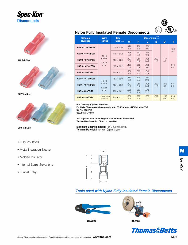
Nylon Fully Insulated Female DisconnectsCatalog Wire Tab DimensionNumber Range Size
inchmm
W F L B D T
16-14A.W.G.
1.5-2.5mm2
22-16A.W.G.
0.5-1.5mm2
KNF18-110-20FDM .110 x .020.126 .252 .7563.2 6.4 19.2
KNF18-110-32FDM .110 x .032.126 .252 .7563.2 6.4 19.2
KNF18-187-20FDM .187 x .020.197 .256 .795 .433 .1575.0 6.5 20.2 11.0 4.0
KNF18-187-32FDM .187 x .032.197 .256 .795 .0165.0 6.5 20.2 0.4
KNF18-250FD-D .250 x .032.260 .303 .8466.6 7.7 21.5
KNF14-187-20FDM .187 x .020.197 .256 .7955.0 6.5 20.2
KNF14-187-32FDM .187 x .032.197 .256 .795 .433 .256 .0165.0 6.5 20.2 11.0 6.0 0.4
KNF14-250FD-M .250 x .032.260 .287 .8466.6 7.3 21.5
KNF10-250FD-D .250 x .032.260 .287 .953 .512 .256 .0166.6 7.3 24.2 13.0 6.5 0.4
.0120.3
12-10 A.W.G.4-6 mm2
110 Tab Size
187 Tab Size
250 Tab Size
Box Quantity: (D)=500; (M)=1000For Mylar Tape replace box quantity with (T). Example: KNF18-110-20FD-TUL File #E66716CSA File #LR4503
See pages in back of catalog for complete tool information.Tool and Die Selection Chart on page M42.
Maximum Electrical Rating: 105˚C 600 Volts Max.Terminal Material: Brass with Copper Sleeve
• Fully Insulated
• Metal Insulation Sleeve
• Molded Insulator
• Internal Barrel Serrations
• Funnel Entry
inch
®
®
ERG2500
Tools used with Nylon Fully Insulated Female Disconnects
KT-2500
M
Spec-Kon®
412031.M01 SPEC 3/5 3/14/03 10:42 AM Page 27
Disconnects
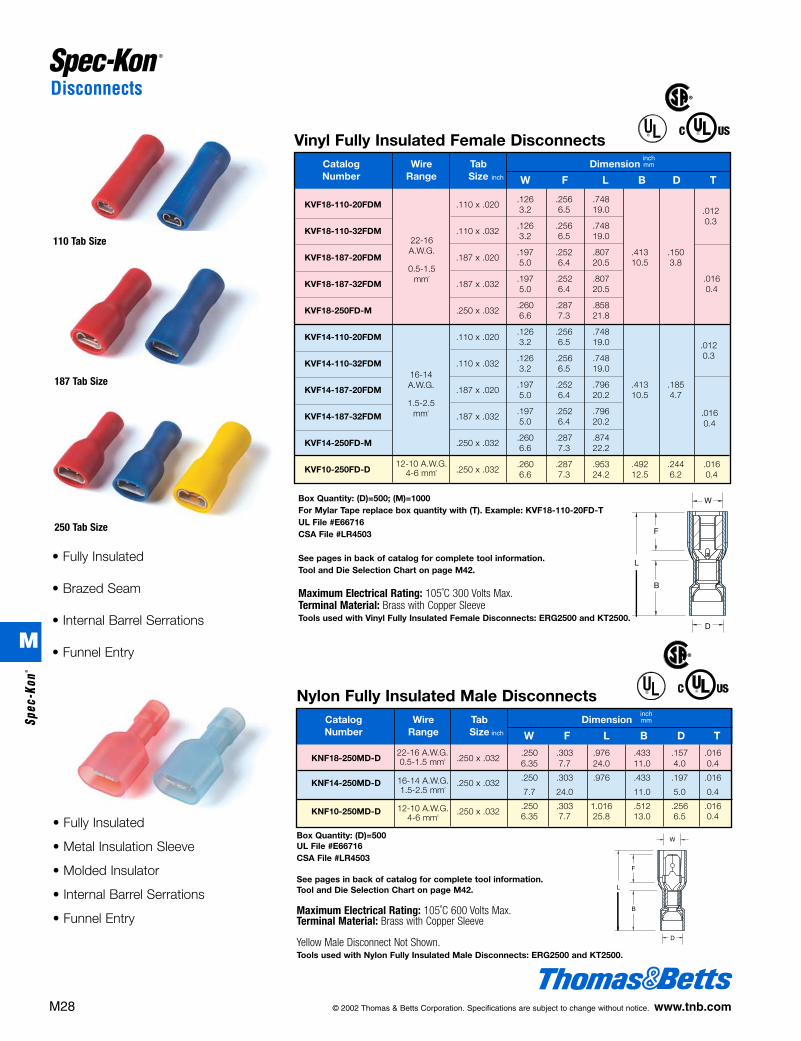
Vinyl Fully Insulated Female DisconnectsCatalog Wire Tab DimensionNumber Range Size
inchmm
W F L B D T
16-14A.W.G.
1.5-2.5mm2
22-16A.W.G.
0.5-1.5mm2
KVF18-110-20FDM .110 x .020.126 .256 .7483.2 6.5 19.0
KVF18-110-32FDM .110 x .032.126 .256 .7483.2 6.5 19.0
KVF18-187-20FDM .187 x .020.197 .252 .807 .413 .1505.0 6.4 20.5 10.5 3.8
KVF18-187-32FDM .187 x .032.197 .252 .807 .0165.0 6.4 20.5 0.4
KVF18-250FD-M .250 x .032.260 .287 .8586.6 7.3 21.8
KVF14-110-20FDM .110 x .020.126 .256 .7483.2 6.5 19.0
KVF14-110-32FDM .110 x .032.126 .256 .7483.2 6.5 19.0
KVF14-187-20FDM .187 x .020.197 .252 .796 .413 .1855.0 6.4 20.2 10.5 4.7
KVF14-187-32FDM .187 x .032.197 .252 .7965.0 6.4 20.2
KVF14-250FD-M .250 x .032.260 .287 .8746.6 7.3 22.2
KVF10-250FD-D .250 x .032.260 .287 .953 .492 .244 .0166.6 7.3 24.2 12.5 6.2 0.4
.0120.3
.0120.3
.0160.4
12-10 A.W.G.4-6 mm2
110 Tab Size
187 Tab Size
250 Tab Size
Box Quantity: (D)=500; (M)=1000For Mylar Tape replace box quantity with (T). Example: KVF18-110-20FD-TUL File #E66716CSA File #LR4503
See pages in back of catalog for complete tool information.Tool and Die Selection Chart on page M42.
Maximum Electrical Rating: 105˚C 300 Volts Max.Terminal Material: Brass with Copper SleeveTools used with Vinyl Fully Insulated Female Disconnects: ERG2500 and KT2500.
• Fully Insulated
• Brazed Seam
• Internal Barrel Serrations
• Funnel Entry
inch
Nylon Fully Insulated Male DisconnectsCatalog Wire Tab DimensionNumber Range Size
KNF18-250MD-D .250 x .032.250 .303 .976 .433 .157 .0166.35 7.7 24.0 11.0 4.0 0.4
KNF14-250MD-D .250 x .032.250 .303 .976 .433 .197 .016
7.7 24.0 11.0 5.0 0.4
KNF10-250MD-D .250 x .032.250 .303 1.016 .512 .256 .0166.35 7.7 25.8 13.0 6.5 0.4
inchmm
W F L B D T
22-16 A.W.G.0.5-1.5 mm2
16-14 A.W.G.1.5-2.5 mm2
Box Quantity: (D)=500UL File #E66716CSA File #LR4503
See pages in back of catalog for complete tool information.Tool and Die Selection Chart on page M42.
Maximum Electrical Rating: 105˚C 600 Volts Max.Terminal Material: Brass with Copper Sleeve
Yellow Male Disconnect Not Shown.Tools used with Nylon Fully Insulated Male Disconnects: ERG2500 and KT2500.
• Fully Insulated
• Metal Insulation Sleeve
• Molded Insulator
• Internal Barrel Serrations
• Funnel Entry
12-10 A.W.G.4-6 mm2
inch
®
®
®
®
M28 © 2002 Thomas & Betts Corporation. Specifications are subject to change without notice. www.tnb.com
M
Spec
-Kon
®
412031.M01 SPEC 3/5 3/14/03 10:42 AM Page 28

Catalog Wire Tab DimensionNumber Range Size
KNF18-187-20BFD-D .187 x .020.197 .244 .748 .555 .433 .137 .0155.0 6.2 19.0 14.1 11.0 3.5 0.4
KNF18-187-32BFD-D .187 x .032.197 .244 .748 .555 .433 .137 .0155.0 6.2 19.0 14.1 11.0 3.5 0.4
KNF18-250BFD-D .250 x .032 .260 .307 .818 .653 .433 .157 .0156.6 7.8 20.8 16.6 11.0 4.0 0.4
KNF14-250BFD-D .250 x .032.260 .307 .818 .653 .433 .177 .0156.6 7.8 20.8 16.6 11.0 4.5 0.4
KNF10-250BFD-D .250 x .032 .260 .307 .905 .697 .511 .248 .0156.6 7.8 23.0 17.7 13.0 6.3 0.4
W F L L 1 B D T
Disconnects
Nylon Fully Insulated Female Flag DisconnectsCatalog Wire Tab DimensionNumber Range Size
inchmm
W F L d1 T
16-14A.W.G.
1.5-2.5mm2
22-18A.W.G.
0.5-1.5mm2
KNF18-187-20FFD-M .187 x .020.197 .276 .5915.0 7.0 15.0
KNF18-187-32FFD-M .187 x .032.197 .276 .591 .063 .0165.0 7.0 15.0 1.6 0.4
KNF18-250FFD-M .250 x .032.260 .299 .5986.6 7.6 15.2
KNF14-187-20FFD-M .187 x .020.197 .276 .5985.0 7.0 15.2
KNF14-187-32FFD-M .187 x .032.197 .276 .598 .083 .0165.0 7.0 15.2 2.1 0.4
KNF14-250FFD-M .250 x .032.260 .299 .5986.6 7.6 15.2
Box Quantity: (W)=250; (D)=500; (M)=1000
See pages in back of catalog for complete tool information.Tool and Die Selection Chart on page M42.
Maximum Electrical Rating: 105˚C 300 Volts Max.Terminal Material: Brass
• Fully Insulated
• Molded Funnel Entry Insulator
• Internal Barrel Serrations
inch
Nylon Fully Insulated Barrel FlagFemale Disconnects
• Fully Insulated
• Molded Funnel Entry Insulator
• Internal Barrel Serrations
inchmm
inch
22-18A.W.G.
0.5-1.5mm2
16-14A.W.G.
12-10A.W.G.
Box Quantity: (W)=250; (D)=500; (M)=1000For Mylar Tape replace box quantity with (T).Example: KVF18-110-20FD-T
See pages in back of catalog for complete toolinformation.
Tool and Die Selection Chart on page M42.Maximum Electrical Rating: 105˚C 600 Volts Max.Terminal Material: Brass
®
W T
C
L1 Tools used with Nylon Fully Insulated Female Flag Disconnects and Nylon Fully Insulated Barrell FlagFemale Disconnects: ERG2500F
© 2002 Thomas & Betts Corporation. Specifications are subject to change without notice. www.tnb.com M29
M
Spec-Kon®
412031.M01 SPEC 3/5 3/14/03 10:42 AM Page 29
Disconnects
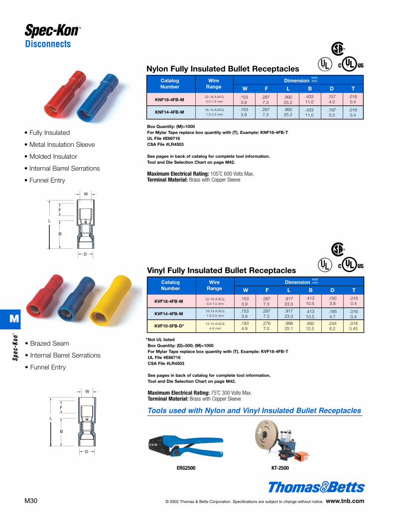
Nylon Fully Insulated Bullet ReceptaclesCatalog Wire DimensionNumber Range
KNF18-4FB-M.153 .287 .9923.9 7.3 25.2
KNF14-4FB-M.153 .287 .9923.9 7.3 25.2
.433 .157 .01611.0 4.0 0.4
.433 .197 .01611.0 5.0 0.4
inchmm
W F L B D T22-16 A.W.G.0.5-1.5 mm2
16-14 A.W.G.1.5-2.5 mm2
12-10 A.W.G.4-6 mm2
Vinyl Fully Insulated Bullet ReceptaclesCatalog Wire DimensionNumber Range
KVF18-4FB-M.153 .287 .9173.9 7.3 23.3
KVF14-4FB-M.153 .287 .9173.9 7.3 23.3
KVF10-5FB-D*.193 .276 .9884.9 7.0 25.1
.413 .150 .01610.5 3.8 0.4
.413 .185 .01610.5 4.7 0.4
inchmm
W F L B D T
22-16 A.W.G.0.5-1.5 mm2
16-14 A.W.G.1.5-2.5 mm2
.492 .244 .01812.5 6.2 0.45
Box Quantity: (M)=1000For Mylar Tape replace box quantity with (T). Example: KNF18-4FB-TUL File #E66716CSA File #LR4503
See pages in back of catalog for complete tool information.Tool and Die Selection Chart on page M42.
Maximum Electrical Rating: 105˚C 600 Volts Max.Terminal Material: Brass with Copper Sleeve
*Not UL listedBox Quantity: (D)=500; (M)=1000For Mylar Tape replace box quantity with (T). Example: KVF18-4FB-TUL File #E66716CSA File #LR4503
See pages in back of catalog for complete tool information.Tool and Die Selection Chart on page M42.
Maximum Electrical Rating: 75˚C 300 Volts Max.Terminal Material: Brass with Copper Sleeve
• Fully Insulated
• Metal Insulation Sleeve
• Molded Insulator
• Internal Barrel Serrations
• Funnel Entry
• Brazed Seam
• Internal Barrel Serrations
• Funnel Entry
M30 © 2002 Thomas & Betts Corporation. Specifications are subject to change without notice. www.tnb.com
®
®
®
®
ERG2500
Tools used with Nylon and Vinyl Insulated Bullet Receptacles
KT-2500
M
Spec
-Kon
®
412031.M01 SPEC 3/5 3/14/03 10:42 AM Page 30
© 2002 Thomas & Betts Corporation. Specifications are subject to change without notice. www.tnb.com M31
Disconnects
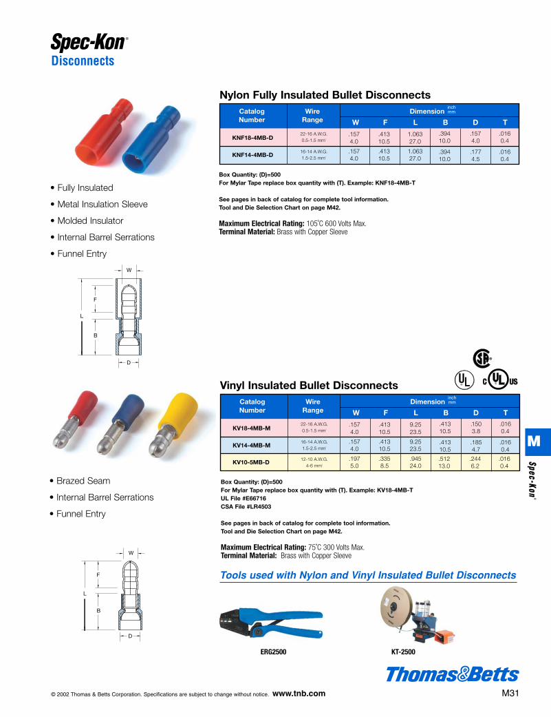
Nylon Fully Insulated Bullet DisconnectsCatalog Wire DimensionNumber Range
KNF18-4MB-D.157 .413 1.0634.0 10.5 27.0
KNF14-4MB-D.157 .413 1.0634.0 10.5 27.0
.394 .157 .01610.0 4.0 0.4
.394 .177 .01610.0 4.5 0.4
inchmm
W F L B D T22-16 A.W.G.0.5-1.5 mm2
16-14 A.W.G.1.5-2.5 mm2
12-10 A.W.G.4-6 mm2
Vinyl Insulated Bullet DisconnectsCatalog Wire DimensionNumber Range
KV18-4MB-M.157 .413 9.254.0 10.5 23.5
KV14-4MB-M.157 .413 9.254.0 10.5 23.5
KV10-5MB-D.197 .335 .9455.0 8.5 24.0
.413 .150 .01610.5 3.8 0.4
.413 .185 .01610.5 4.7 0.4
inchmm
W F L B D T22-16 A.W.G.0.5-1.5 mm2
16-14 A.W.G.1.5-2.5 mm2
.512 .244 .01613.0 6.2 0.4
Box Quantity: (D)=500For Mylar Tape replace box quantity with (T). Example: KNF18-4MB-T
See pages in back of catalog for complete tool information.Tool and Die Selection Chart on page M42.
Maximum Electrical Rating: 105˚C 600 Volts Max.Terminal Material: Brass with Copper Sleeve
• Fully Insulated
• Metal Insulation Sleeve
• Molded Insulator
• Internal Barrel Serrations
• Funnel Entry
Box Quantity: (D)=500For Mylar Tape replace box quantity with (T). Example: KV18-4MB-TUL File #E66716CSA File #LR4503
See pages in back of catalog for complete tool information.Tool and Die Selection Chart on page M42.
Maximum Electrical Rating: 75˚C 300 Volts Max.Terminal Material: Brass with Copper Sleeve
• Brazed Seam
• Internal Barrel Serrations
• Funnel Entry
®
®
ERG2500
Tools used with Nylon and Vinyl Insulated Bullet Disconnects
KT-2500
M
Spec-Kon®
412031.M01 SPEC 3/5 3/14/03 10:42 AM Page 31

Splices, Wire Joints, and Quick Splices
Splices / Wire Joints / Quick Splices• Ideal for in-line splicing.
• Butt Splices available in Nylon, Vinyl, and non-insulated types.
• Vinyl Quick Splices are color-coded for wire ranges, and providequick, easy in-line splicing and tapping.
• Nylon wire joint provides long-lasting, durable connection and canaccommodate multiple leads. Rated 300 V at 105ºC.
• Available in 22-10 AWG.
Butt SpliceIdeal for in-line splicing applications
Wire JointsProvides terminating pointfor a group of wires runningin one direction
Design Features of Splices, Wire Joints and Quick Splices
Quick SplicesGreat for quick in-line splicingand tapping without strippingthe wire insulation
Features and Benefits
M32 © 2002 Thomas & Betts Corporation. Specifications are subject to change without notice. www.tnb.com
Performance Requirements
Description
U.L. 486A (Terminals)
Test Current for Max. 50˚C Rise (Amps)
Min. Tensile Strength* (Lbs.)
9 12 17 18 30 35 50 70 95 125 145
8 13 20 30 50 70 80 90 100 140 160
#22 #20 #18 #16 #14 #12 #10 #8 #6 #4 #2
Wire Size (AWG)
Applicable Spec-Kon® products meet or exceed the following test specifications:• UL486A (Terminals)
• CSA
• UL486C (Splices)
UL listed products are shown with the applicable logos in the product section.
UL file #E9809 (Terminals).
CSA file #LR4503
* Pull-out force of the crimped terminal.
M
Spec
-Kon
®
412031.M01 SPEC 3/5 3/14/03 10:43 AM Page 32
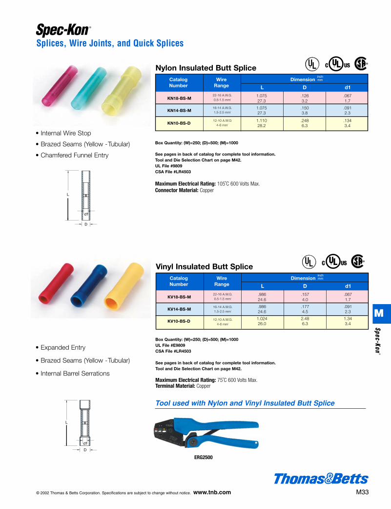
Nylon Insulated Butt SpliceCatalog Wire DimensionNumber Range
KN18-BS-M1.075 .126 .06727.3 3.2 1.7
KN14-BS-M1.075 .150 .09127.3 3.8 2.3
KN10-BS-D1.110 .248 .13428.2 6.3 3.4
inchmm
L D d122-16 A.W.G.0.5-1.5 mm2
16-14 A.W.G.1.5-2.5 mm2
Box Quantity: (W)=250; (D)=500; (M)=1000
See pages in back of catalog for complete tool information.Tool and Die Selection Chart on page M42.UL File #9809CSA File #LR4503
Maximum Electrical Rating: 105˚C 600 Volts Max.Connector Material: Copper
• Internal Wire Stop
• Brazed Seams (Yellow -Tubular)
• Chamfered Funnel Entry
12-10 A.W.G4-6 mm2
®
®
© 2002 Thomas & Betts Corporation. Specifications are subject to change without notice. www.tnb.com M33
Splices, Wire Joints, and Quick Splices
Vinyl Insulated Butt SpliceCatalog Wire DimensionNumber Range
KV18-BS-M.986 .157 .06724.6 4.0 1.7
KV14-BS-M.986 .177 .09124.6 4.5 2.3
KV10-BS-D1.024 2.48 1.3426.0 6.3 3.4
inchmm
L D d122-16 A.W.G.0.5-1.5 mm2
16-14 A.W.G.1.5-2.5 mm2
Box Quantity: (W)=250; (D)=500; (M)=1000UL File #E9809CSA File #LR4503
See pages in back of catalog for complete tool information.Tool and Die Selection Chart on page M42.
Maximum Electrical Rating: 75˚C 600 Volts Max.Terminal Material: Copper
• Expanded Entry
• Brazed Seams (Yellow -Tubular)
• Internal Barrel Serrations
12-10 A.W.G.4-6 mm2
®
®
ERG2500
Tool used with Nylon and Vinyl Insulated Butt Splice
M
Spec-Kon®
412031.M01 SPEC 3/5 3/14/03 10:43 AM Page 33

Splices, Wire Joints, and Quick Splices
Nylon Insulated Wire JointCatalog Wire DimensionNumber Range
KN18-WJ-M.209 .315 .8275.3 8.0 21.0
KN14-WJ-M.236 .354 .8276.0 9.0 21.0
KN10-WJ-D.299 .394 1.0047.6 10.0 25.5
22-16 A.W.G.1.25 mm2
16-14 A.W.G.2 mm2
12-10 A.W.G.5.5 mm2
.386 .276 .020 .0919.8 7.0 0.5 2.3
.394 .276 .020 .12210.0 7.0 0.5 3.1
.492 .295 .028 .15712.5 7.5 0.7 4.0
inchmm
W F L D E T C
12-10 A.W.G.4-6 mm2
Vinyl Insulated Quick SpliceCatalog Wire DimensionNumber Range
KV14-OOQS-D.787 1.06320.0 27.0
KV18-OOQS-D.787 1.06320.0 27.0
KV10-OOQS*.807 1.35820.5 34.5
inchmm
W L Color22-18 A.W.G.0.5-1.0 mm2
18-14 A.W.G..75-2.5 mm2
red
blue
yellow
Box Quantity: (W)=250; (D)=500; (M)=1000UL File #E66716CSA File #LR4503
See pages in back of catalog for complete toolinformation.Tool and Die Selection Chart on page M42.
Maximum Electrical Rating: 105˚C 300 Volts Max.Terminal Material: Copper Tube
Box Quantity: (W)=250; (D)=500; (M)=1000* 200 piece quantity only.See pages in back of catalog for complete tool information.Tool and Die Selection Chart on page M42.
Maximum Electrical Rating: 105˚C 600 Volts Max.Terminal Material: Brass
12-10 A.W.G.4-6 mm2
Non-Insulated Butt SpliceCatalog Wire DimensionNumber Range
K18-BS-M.591 .130 .067 .03115.0 3.3 1.7 0.8
K14-BS-M.591 .154 .091 .03115.0 3.9 2.3 0.8
K10-BS-M.591 .213 .134 .03915.0 5.4 3.4 1.0
inchmm
L D d1 T22-16 A.W.G.0.5-1.5 mm2
16-14 A.W.G.1.5-2.5 mm2
• Chamfered Barrel Entry
• Seamless Barrel Construction
• Wire Stop
Box Quantity: (M)=1000UL File #E9809CSA File #LR4503
See pages in back of catalog for complete toolinformation.Tool and Die Selection Chart on page M42.
Terminal Material: Copper Tubular
M34 © 2002 Thomas & Betts Corporation. Specifications are subject to change without notice. www.tnb.com
®
®
®
®
ERG2002
Tool used with Non-InsulatedButt Splice
ERG2500WJ
Tool used with NylonInsulated Wire Joint
M
Spec
-Kon
®
412031.M01 SPEC 3/5 3/14/03 10:43 AM Page 34

© 2002 Thomas & Betts Corporation. Specifications are subject to change without notice. www.tnb.com M35
Hand Tools
22 - 16 AWG .080 - .088ERG-2500 16 - 14 AWG .091 - .099
12 - 10 AWG .119 - .12722 - 16 AWG .067 - .062
ERG-2002 16 - 14 AWG .089 - .08412 - 10 AWG .115 - .110
ERG-2500F 22 - 14 AWG –
ERG-2500WJ 22 - 10 AWG –
Catalog Gauging Number Wire Range (inches)
Tool Gauging Requirements
ERG-2500 All Insulated Terminals, Splices, & Disconnects (except Flags) 22 - 10 AWG
ERG-2002 All Non-Insulated Terminals, Splices, & Disconnects 22 - 10 AWG
ERG-2500F Nylon Fully Insulated Female Flag Disconnects 22 - 14 AWG
ERG-2500WJ Nylon Insulated Wire Joint 22 - 10 AWG
ERG2002
ERG2500
Ergonomic ratchet style hand tool used for installing insulated Spec-Kon®
terminals. Specially designed ergonomic handles distributes the crimpingforce evenly across the user’s hands. Helps reduce the risk of Carpal Tunnel Syndrome, the cause of almost one of every two industrial injuries.Ratchet design greatly reduces handle forces over conventional hand tools and incorporates the Shure-Stake® mechanism which ensures fullcompression every time. Color coded die nests (insulated only) facilitatesgetting the right terminal in the right nest.
Comfort Crimp® Terminal ToolsERG-2500, ERG-2500F, ERG-2002, ERG-2500WJ
CatalogNumber Terminal Style Wire Range
• Installs Nylon and Vinyl Insulated
Terminals, Disconnects, and Splices
22-10 AWG
• The force required to release the
Shure-Stake® mechanism should
be no less than 20 lbs.
* Contact Customer Service for availability of this product. Longer lead times may be required.
• Installs Non-Insulated Terminals,
Disconnects, and Splices 22-10 AWG
• The force required to release the
Shure-Stake® mechanism should
be no less than 15 lbs.
ERG2500WJ
M
Spec-Kon®
412031.M01 SPEC 3/5 3/14/03 10:43 AM Page 35
Hand Tools
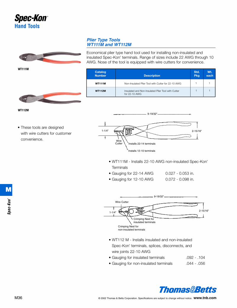
Catalog Std. Wt.Number Description Pkg each
WT111M Non-Insulated Plier Tool with Cutter for 22-10 AWG
WT112M Insulated and Non-Insulated Plier Tool with Cutter for 22-10 AWG
1 1
Economical plier type hand tool used for installing non-insulated and insulated Spec-Kon® terminals. Range of sizes include 22 AWG through 10AWG. Nose of the tool is equipped with wire cutters for convenience.
1 1
WT111M
WT112M
Plier Type ToolsWT111M and WT112M
• WT111M - Installs 22-10 AWG non-insulated Spec-Kon®
Terminals
• Gauging for 22-14 AWG 0.027 - 0.053 in.
• Gauging for 12-10 AWG 0.072 - 0.098 in.
• WT112 M - Installs insulated and non-insulated
Spec-Kon® terminals, splices, disconnects, and
wire joints 22-10 AWG
• Gauging for insulated terminals .092 - .104
• Gauging for non-insulated terminals .044 - .056
WireCutter Installs 22-14 terminals
Installs 12-10 terminals
2-15/16"1-1/4"
9-19/32"
• These tools are designed
with wire cutters for customer
convenience.
2-15/16"1-1/4"
Wire Cutter
Crimping Nest fornon-insulated terminals
Crimping Nest forinsulated terminals
9-19/32"
M36 © 2002 Thomas & Betts Corporation. Specifications are subject to change without notice. www.tnb.com
M
Spec
-Kon
®
412031.M01 SPEC 3/5 3/14/03 10:43 AM Page 36

© 2002 Thomas & Betts Corporation. Specifications are subject to change without notice. www.tnb.com M37
Hand Tools
Toggle type hand tool for installing large insulated and non-insulated Spec-Kon® terminals. Terminal size ranges from #8 AWG through #2 AWGMCM. Interchangeable dies are ordered separately. The TBM6S featuresthe Shure-Stake® mechanism which ensures full compression every time.
Nest Indentor GaugingStationary Die Movable Die Terminal Size (inches)
Installing dies for non-insulated Spec-Kon® terminals
11805 11802 8 - 6 AWG .157-.177
11806 11802 4 AWG .196-.216
11807 11802 2 AWG .224-.244
Installing dies for insulated Spec-Kon® terminals
11822 – 8 AWG .192 - .212
11823 – 6 AWG .244-.264
TBM6
TBM6S
Toggle Type ToolsTBM6 and TBM6S
Catalog Terminal Size Std. Wt.Number For use with Spec-Kon® Pkg each
TBM6 8 - 2 AWG
TBM6S 8 - 2 AWG 1 9
1 9
Installing Dies
• For use with
non-insulated terminals
Cat No. TBM6 and TBM6S
• For use with
insulated terminals
Cat No. TBM6 and TBM6S
M
Spec-Kon®
412031.M01 SPEC 3/5 3/14/03 10:43 AM Page 37

M38 © 2002 Thomas & Betts Corporation. Specifications are subject to change without notice. www.tnb.com
Automated Tools
The Universal Applicator from Thomas & Betts offers a uniqueopportunity to use the range of quality Spec-Kon tape-mountedterminals on your own machine. If you have the press already,there’s no need for additional costly investments on your plant
floor to convert to another terminal. Our applicator will handlethe entire range of Mylar-tape fed terminals offered in theSpec-Kon product line, and allows you more flexibility onyour production line. Fast and simple. If you have the press,
we’ve got the applicator.
Spec-Kon® Universal Applicator includes these prominent features:
• Allows industry-standard presses to use Spec-Kon® TerminalProducts (AMP-compatible).
• Includes stand-alone presses.
• Also compatible with major brands of wire processing equipment.
• One single part – no additional accessories needed (excluding dies).
• Quick-change of tooling / dies in minutes – simply done with an Allen wrench.
• Convenient Crimp Height adjustment for range of crimping force fine-tuning.
• 22-10 AWG Range.
• Crimps Insulated and Uninsulated Spec-Kon®
terminals.
• Crimps Nylon and Vinyl insulation terminals.
• All-metallic construction for years of use.
• Creates UL Listed Crimps.
• One year warranty, excluding dies.
Universal Applicator
AMP is a registered trademark of Tyco Electronics Corporation
The new Spec-Kon Universal Applicator is designed forquick terminal conversions in plant equipment such as theApplitek press.
Catalog Std. Wt.Number Description Pkg each
KT2500UA Spec-Kon® Universal Applicator 1 17 lbs.
Dimensions: 7.5” x 5.75” x 4.25”Range: 22 AWG - 10 AWG Insulated and NoninsulatedSee instruction manual for complete maintenance, installation and operating characteristics for this tool.
Catalog WireNumber Description Range
KT-18Z Insulated Terminals, Disconnects, & Splices 22-16 AWG
KT-14Z Insulated Terminals, Disconnects, & Splices 16-14 AWG
KT-10Z Insulated Terminals, Disconnects, & Splices 12-10 AWG
KTU-18Z Insulated Terminals, Disconnects, & Splices 22-16 AWG
KTU-14Z Insulated Terminals, Disconnects, & Splices 16-14 AWG
KTU-10Z Insulated Terminals, Disconnects, & Splices 12-10 AWG
Die Chart
M
Spec
-Kon
®
NEW
412031.M01 SPEC 3/5 3/14/03 10:43 AM Page 38
Automated Tools
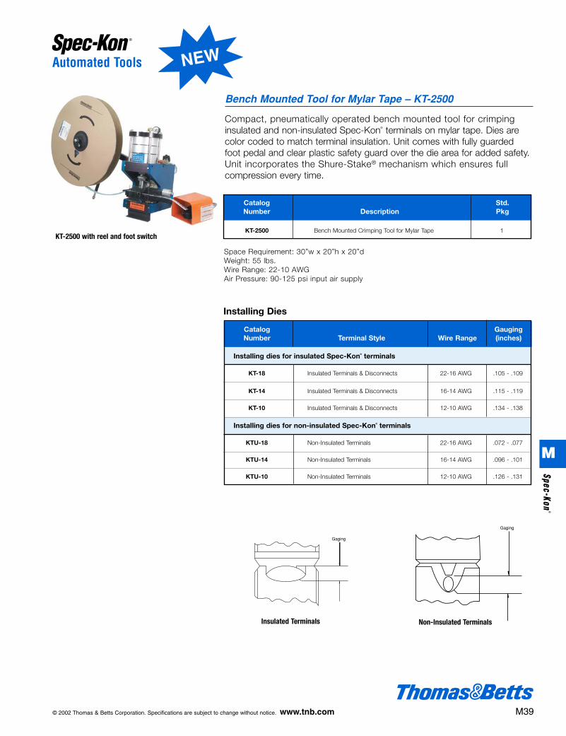
Compact, pneumatically operated bench mounted tool for crimping insulated and non-insulated Spec-Kon® terminals on mylar tape. Dies arecolor coded to match terminal insulation. Unit comes with fully guardedfoot pedal and clear plastic safety guard over the die area for added safety.Unit incorporates the Shure-Stake® mechanism which ensures fullcompression every time.
Bench Mounted Tool for Mylar Tape – KT-2500
KT-2500 with reel and foot switch
Catalog GaugingNumber Terminal Style Wire Range (inches)
Installing dies for insulated Spec-Kon® terminals
KT-18 Insulated Terminals & Disconnects 22-16 AWG .105 - .109
KT-14 Insulated Terminals & Disconnects 16-14 AWG .115 - .119
KT-10 Insulated Terminals & Disconnects 12-10 AWG .134 - .138
Installing dies for non-insulated Spec-Kon® terminals
KTU-18 Non-Insulated Terminals 22-16 AWG .072 - .077
KTU-14 Non-Insulated Terminals 16-14 AWG .096 - .101
KTU-10 Non-Insulated Terminals 12-10 AWG .126 - .131
Installing Dies
Catalog Std.Number Description Pkg
KT-2500 Bench Mounted Crimping Tool for Mylar Tape 1
Space Requirement: 30”w x 20”h x 20”dWeight: 55 lbs.Wire Range: 22-10 AWGAir Pressure: 90-125 psi input air supply
Insulated Terminals Non-Insulated Terminals
© 2002 Thomas & Betts Corporation. Specifications are subject to change without notice. www.tnb.com M39
M
Spec-Kon®
NEW
412031.M01 SPEC 3/5 3/14/03 10:43 AM Page 39

CatalogNumber Description Wt. (lb.)
Power Operated Tools
Compact, portable, battery operated tool for crimping loose piece insulatedand non-insulated Spec-Kon® terminals. Dies are color coded to matchterminal insulation. Multi-nested die used for non-insulated which reducessetup time. Unit incorporates the Shure-Stake® mechanism which ensuresfull compression every time.
ERG3000 Battery Powered Tool
• Start button initiates crimping work cycle.
• Safety catch protects fingerswhen changing die sets.
• Compact tool head operates intight spaces and weighs just 1.65 pounds to reduce fatigue.
• Swivel head improves access to small spaces.
• Control lever opens jaws for terminal installation and die change.
• Interchangeable dies accommodate Spec-Kon® terminals from 22-10 AWG.
• Easy-to-see indicator lamps show when ERG 3000 is ready to operate or in a work cycle.
• Portable base power unit houses the battery, hydraulic pump, fluid reservoir, and electronic control unit.
• Durable, flexible 8.2 foot hose connects the tool head to the base power unit for extra reach.
Standard Components Note: The part number ERG-3000 refers to a complete kit consisting of one ERG-3001,one ERG-3002, two ERG-3003, one ERG-3004, and one ERG-3005.
ERG-3001 Base Unit 11.0
ERG-3002 Hose & Tool Head Assembly 3.5
ERG-3003 NiCd Battery 1.3
ERG-3004 15 min. Battery Charge 3.0
ERG-3005 Carrying Case 6.3
ERG-3006 AC Adapter 7.0
ERG-3007 Benchmount 1.0
ERG-3008 Switch 2.5
ERG-3000 Complete Kit (see note below) 26.4
Catalog GaugingNumber Terminal Style Wire Range (inches)
Installing dies for insulated Spec-Kon® terminals
KT-18Y Insulated Terminals & Disconnects 22-16 AWG .105 - .109
KT-14Y Insulated Terminals & Disconnects 16-14 AWG .115 - .119
KT-10Y Insulated Terminals & Disconnects 12-10 AWG .134 - .138
Installing dies for non-insulated Spec-Kon® terminals
KTU-2214Y Non-Insulated Terminals (Two Nested Die Set)22-16 AWG .072 - .077
16-14 AWG .096 - .101
KTU-10Y Non-Insulated Terminals 12-10 AWG .126 - .131
Installing Dies
M40 © 2002 Thomas & Betts Corporation. Specifications are subject to change without notice. www.tnb.com
Technical Data
Base UnitWorking pressure 3625 psiPower supply NiCd Battery 12 V DC or
AC/DC converter 110 V60 Hz
Work cycle 1.5-3 secondsWeight (with battery) 11 lb. (without tool/hose
pack)Dimensions 13.77"L x 7.28" W x
5.12" DTemperature range -4° to 122°F
Tool Head AssemblyPress force 3371 lbfWeight (tool only) 1.65 lb.Diameter of handle 1.61 in.Length of handle 8.86 in.Length of hose 7.22 ft.BatteryType NiCd 12 V, rechargeableRecharging time 15 min.Number of recharges 1000
M
Spec
-Kon
®
412031.M01 SPEC 3/5 3/14/03 10:43 AM Page 40
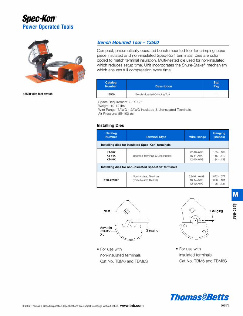
Power Operated Tools
Compact, pneumatically operated bench mounted tool for crimping loosepiece insulated and non-insulated Spec-Kon® terminals. Dies are colorcoded to match terminal insulation. Multi-nested die used for non-insulatedwhich reduces setup time. Unit incorporates the Shure-Stake® mechanismwhich ensures full compression every time.
Bench Mounted Tool – 13500
13500 with foot switch
Catalog Std.Number Description Pkg
13500 Bench Mounted Crimping Tool 1
Space Requirement: 8" X 12"Weight: 10-12 lbs.Wire Range: 8AWG - 2AWG Insulated & Uninsulated Terminals.Air Pressure: 85-100 psi
© 2002 Thomas & Betts Corporation. Specifications are subject to change without notice. www.tnb.com M41
• For use with
non-insulated terminals
Cat No. TBM6 and TBM6S
• For use with
insulated terminals
Cat No. TBM6 and TBM6S
Catalog GaugingNumber Terminal Style Wire Range (inches)
Installing Dies
Installing dies for insulated Spec-Kon® terminals
KT-18X 22-16 AWG .105 - .109KT-14X Insulated Terminals & Disconnects 16-14 AWG .115 - .119KT-10X 12-10 AWG .134 - .138
Installing dies for non-insulated Spec-Kon® terminals
Non-Insulated Terminals 22-16 AWG .072 - .077KTU-2210X* (Three Nested Die Set) 16-14 AWG .096 - .101
12-10 AWG .126 - .131
M
Spec-Kon®
412031.M01 SPEC 3/5 3/14/03 10:43 AM Page 41

Application Information
Tool and Die Selection Chart
Erg-3000Plier Ergonomic KT-2500 13500 Power Hand Tool Hand Tool Pneumatic Tool Die Pneumatic Tool Die Tool Die
Part Numbers Part Numbers Part Numbers
Nylon TerminalWT112M ERG-2500 KT-18 KT-14 KT-10 KT-18X KT-14X KT-10X KT-18Y KT-14Y KT-10Y(22-10 AWG)
NylonWT112M ERG-2500 N/A N/A N/A KT-18X KT-14X KT-10X KT-18Y KT-14Y KT-10YButt Splice
NylonWT112M ERG-2500 KT-18 KT-14 KT-10 KT-18X KT-14X KT-10X KT-18Y KT-14Y KT-10YDisconnect
Nylon TerminalTBM6 N/A KT-8 KT-6 N/A N/A N/A N/A N/A N/A N/A(8-6 AWG)
Vinyl TerminalWT112M ERG-2500 KT-18 KT-14 KT-10 KT-18X KT-14X KT-10X KT-18Y KT-14Y KT-10Y(22-10 AWG)
VinylWT112M ERG-2500 KT-18 KT-14 KT-10 KT-18X KT-14X KT-10X KT-18Y KT-14Y KT-10YButt Splice
VinylWT112M ERG-2500 KT-18 KT-14 KT-10 KT-18X KT-14X KT-10X KT-18Y KT-14Y KT-10YDisconnect
Non InsulatedWT111M ERG-2002 KTU-18 KTU-14 KTU-10
KTU- KTU- KTU- KTU-2214Y KTU-2214Y KTU-2214YTerminal2210X 2210X 2210X KTU-10Y KTU-10Y KTU-10Y(22-10 AWG)
Non Insulated WT111M ERG-2002 N/A N/A N/A KTU- KTU- KTU- KTU-2214Y KTU-2214Y KTU-2214YButt Splice 2210X 2210X 2210X KTU-10Y KTU-10Y KTU-10Y
Non InsulatedTBM6 N/A N/A N/A N/A KTU-8 KTU-6 N/A N/A N/A N/ATerminal
(8-6 AWG)
WireWT112M ERG-2500WJ N/A N/A N/A N/A N/A N/A N/A N/A N/AJoints
FlagN/A ERG-2500F N/A N/A N/A N/A N/A N/A N/A N/A N/ATerminals
Spec-Kon®
Terminals
Strip Length Chart
Non-Insulated Terminals
Vinyl Insulated Terminals
Nylon Insulated Terminals
Vinyl Insulated Disconnects
Nylon Insulated Disconnects
Vinyl Insulated Butt Splices
Nylon Insulated Butt Splices
Nylon Wire Joints
Description Terminal Wire StripSeries Length
K18 1/4”K14 1/4”K10 5/16”K8 3/8”K6 7/16”K4 1/2"K2 9/16"
KV18 1/4”KV14 1/4”KV10 5/16”KV8 3/8"KV6 7/16"
KN18 1/4”KN14 1/4”KN10 5/16”KN8 3/8”KN6 7/16”KV18 1/4”KV14 1/4”KV10 5/16”KN18 1/4”KN14 1/4”KN10 5/16”KV18 5/16”KV14 5/16”KV10 5/16”KN18 1/4”KN14 1/4”KN10 1/4”K18 9/32”K14 9/32”K10 11/32”
KNor
KNF
KVor
KVF
K
KNor
KNF
M42 © 2002 Thomas & Betts Corporation. Specifications are subject to change without notice. www.tnb.com
M
Spec
-Kon
®
412031.M01 SPEC 3/5 3/14/03 10:43 AM Page 42

Application Information
Stud Size Chart
#2 .086 .0902M2 2.18 2.29
#4 .112 .1184M2,5 2.84 3.00
#5 .125 .1275M3 3.18 3.23
#6 .138 .1466M3,5 3.51 3.71
#8 .164 .1738M4 4.17 4.39
#10 .190 .19810M5 4.83 5.03
1/4 .250 .27014M6 6.35 6.86
5/16 .312 .33056M8 7.92 8.38
3/8 .375 .38538M10 9.53 9.78
1/2 .500 .52012M12 12.7 13.21
5/8 .625 .65058M16 15.88 16.51
3/4 .750 .81034M18 19.05 20.57
Standard Stud Terminal Stud SizeStud Size Diameter Hole Dia. Part No.
U.S Inches Inches Designationmm mm
Common Conductor Size ChartIndividual Conductor Size
Strand Size
Circl. MilSize No. of Inches Inches Area
Strands mm mm mm
22AWG 7 .0096 .028 6400.24 0.74 0.74
20AWG 10 .0100 .038 10200.25 0.97 0.519
18AWG 16 .0100 .048 16200.25 1.22 0.823
16AWG 26 .0100 .060 25800.25 1.52 1.310
14AWG 7 .0242 .073 41100.61 1.85 2.080
12AWG 7 .0305 .092 65300.77 2.34 3.310
10AWG 7 .0385 .116 10,3800.98 2.95 5.261
8AWG 7 .0486 .146 16,5101.23 3.71 8.367
6AWG 7 .0612 .184 26,2401.55 4.67 13.30
4AWG 7 .0772 .232 41,7401.96 5.89 21.15
2AWG 7 .0974 .292 66,3602.47 7.42 33.62
1AWG 19 .0664 .332 83,6901.69 8.43 42.41
1/10AWG 19 .0745 .373 105,6001.89 9.47 53.49
2/0AWG 19 .0837 .418 133,1002.13 10.62 67.43
3/0AWG 19 .0940 .470 167,8002.39 11.94 85.01
4/0AWG 19 .1055 .528 211,6002.68 13.41 107.2
250MCM 37 .0822 .575 250,0002.09 14.61 127
300MCM 37 .0900 .630 300,0002.29 16.00 152
350MCM 37 .0973 .681 350,0002.47 17.29 177
400MCM 37 .1040 .728 400,0002.64 18.49 203
500MCM 37 .1162 .813 500,0002.95 20.65 253
600MCM 61 .0992 .893 600,0002.52 22.68 304
750MCM 61 .1109 .998 750,0002.82 25.35 380
800MCM 61 .1145 1.031 800,0002.91 26.19 405
1000MCM 61 .1280 1.152 1,000,0003.25 29.26 507
© 2002 Thomas & Betts Corporation. Specifications are subject to change without notice. www.tnb.com M43
M
Spec-Kon®
412031.M01 SPEC 3/5 3/14/03 10:43 AM Page 43