spect instrumentation and quality assurance resources/practice points...stationary scanner. table 1....
TRANSCRIPT

preferred with Tc-99m-based agents) collimators andlow-energy, all-purpose (generally preferred for Tl-201) collimators are most commonly used. Parallel-hole collimation is most often used in Anger cameras.The use of newer reconstruction algorithms, the doseand type of radionuclide, the patient population test-ed, and collimator choice will vary among laboratories.
SPECT Instrumentation and Quality Assurance
OVERVIEWThe proper choice of equipment to acquireclinical data and a well-designed quality assur-ance (QA) program are both essential to opti-mize diagnostic accuracy and ensure consis-tent, high-quality imaging. This documentwill cover the minimum requirements neededfor a single photon-emission computedtomography (SPECT) camera in cardiac imag-ing as well as the different QA procedures.
MINIMUM SPECT CAMERA REQUIREMENTSSPECT camera designs are based on a number of funda-mental components, all of which play an integral role inthe system performance and choice of a SPECT system.
Detector type: Detector types include scintillationcameras (i.e., Anger), solid-state, pixilated scintillationcrystals, and semiconductor/solid-state detectors. Energy resolution: Energy resolution is an importantdeterminant of image quality. The energy windowneeds to be adjusted for technetium or thallium. Itcan be improved with solid-state detector technology.Spatial Resolution: Spatial resolution is mainly affectedby the collimator in Anger camera designs. The imagereconstruction algorithm and filtering also affect thefinal resolution.Collimators: The collimator is the most importantcomponent of the SPECT system for determiningimage quality. The width and depth of the collimatorsepta control the trade-offs between sensitivity andresolution. Low-energy, high-resolution (generally
Single-head camera
No longer widely used for cardiac applications
Dual-head camera
180 degree orbit, 90 degree separa-tion of detectors for cardiac applica-tion. Camera heads with acute angleconfigurations and longer scan rangemay prevent truncation artifacts.
Triple-head camera
Higher sensitivity for cardiac appli-cations, but greater image noise.
Non-standardcamera
Generally, smaller field of view cam-eras with fixed 90 degree configura-tion. Reduced weight and spacerequirements. Patient positioningmay be reclined or horizontal. Maynot have visible moving compo-nents. Some systems have the patientrotating in an upright chair with astationary scanner.
Table 1. Various SPECT cameras used in cardiac imaging
Camera Design Comments
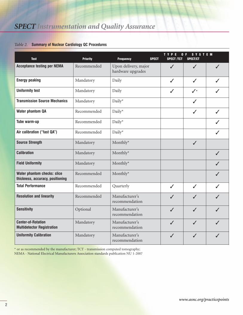
SPECT CAMERA QUALITY ASSURANCEOne of the essential requirements for ensuring consistent,high-quality diagnostic SPECT imaging is a well-designed,multi-component QA program. The general componentsof quality control (QC) procedures are shown in Table 2.
Acceptance testing per NEMA Recommended Upon delivery, majorhardware upgrades
✓ ✓ ✓
Energy peaking Mandatory Daily ✓ ✓ ✓
Uniformity test Mandatory Daily ✓ ✓* ✓
Transmission Source Mechanics Mandatory Daily* ✓
Water phantom QA Recommended Daily* ✓ ✓
Tube warm-up Recommended Daily* ✓
Air calibration (“fast QA”) Recommended Daily* ✓
Source Strength Mandatory Monthly* ✓
Calibration Mandatory Monthly* ✓
Field Uniformity Mandatory Monthly* ✓
Water phantom checks: slicethickness, accuracy, positioning
Recommended Monthly* ✓
Total Performance Recommended Quarterly ✓ ✓ ✓
Resolution and linearity Recommended Manufacturer’s recommendation
✓ ✓ ✓
Sensitivity Optional Manufacturer’s recommendation
✓ ✓ ✓
Center-of-Rotation Multidetector Registration
Mandatory Manufacturer’s recommendation
✓ ✓ ✓
Uniformity Calibration Mandatory Manufacturer’s recommendation
✓ ✓ ✓
Table 2. Summary of Nuclear Cardiology QC Procedures
T Y P E O F S Y S T E MTest Priority Frequency SPECT SPECT /TCT SPECT/CT
SPECT Instrumentation and Quality Assurance
2
* or as recommended by the manufacturer; TCT - transmission computed tomography; NEMA - National Electrical Manufacturers Association standards publication NU 1-2007
www.asnc.org/practicepoints

SPECT Instrumentation and Quality Assurance
3
The optimal way in which to perform specific QA testsvaries considerably between models of imaging equipmentand this document is not intended to replace manufactur-ers’ recommendations. However, if the manufacturer doesnot provide an equivalent test or indicate the frequency ofwhen these tests should be performed as outlined in thissection, the existing guideline protocols and frequenciesshould be enforced.
Here are definitions of the major QA measures shown inTable 2:
Acceptance testing: It is recommended that the NEMA(National Electrical Manufacturers Association) per-formance measurements (NU 1-2007) be made beforeaccepting the SPECT scanner. Many of these tests willbe performed by the company supplying the SPECTscanner.Energy peaking: Energy peaking is performed in orderto verify that the camera is counting photons with thecorrect energy. This test requires either the manual orautomatic placement of the correct pulse height ana-lyzer’s energy window over the photopeak energy to beused. Uniformity test: A uniformity test is performed inorder to verify that the camera’s sensitivity response isuniform across the detector’s face. Two methods ofperforming this test are 1) intrinsic (i.e., using a pointsource without collimators) or 2) extrinsic (i.e., withthe collimator in place in conjunction with a sheetsource, usually of Co-57). Resolution and linearity test: This test is performed inorder to document spatial resolution and its change
over time, as well as the detector’s ability to imagestraight lines. The test consists of imaging a floodsource intrinsically through a spatial resolution testphantom. Center-of-rotation (COR) calibration: An alignmenterror between the center of the electronic matrix ofthe camera and the mechanical COR can potentiallyresult in a characteristic “doughnut” (if a 360 degreeorbit and a point source are used) or “tuning fork”artifact (if a 180 degree orbit is used) in the transverseimages. The effects are most evident when the error isgreater than two pixels in a 64 x 64 matrix. Errors lessthan this reduce spatial resolution.
WHEN TO REPEAT THE SPECT SCAN ACQUISITIONFactors leading to a decision to either delay or abortSPECT imaging include camera-related factors as well aspatient-related factors. Camera-related factors mayinclude malfunctioning due to:
• Analyzer peaking• Uniformity floods• Sensitivity and resolution• COR
If any of these factors are not within an acceptable range,SPECT imaging should not commence, and the Field

4
SPECT Instrumentation and Quality Assurance
clude interpretation, SPECT imaging should be aborteduntil there has been sufficient time for liver clearance andfor the bowel uptake to have moved far enough away fromthe cardiac silhouette to begin imaging.
SUGGESTED READINGHolly TA, Abbott BA, Al-Mallah M, et al. ASNC imagingguidelines for nuclear cardiology procedures: Single pho-ton-emission computed tomography. J Nucl Cardiol2010;17:doi: 10.1007/s12350-010-9246-y.
National Electrical Manufacturers Association. NEMAStandards Publication NU 1-2007: Performance measure-ments of scintillation cameras. Washington, DC: NationalElectrical Manufacturers Association; 2007.
ASNC thanks the following members for their contribu-tions to this document: Writing Group: Mouaz H. Al-Mallah, MD (Chair); Aiden Abidov, MD, PhD; KarthikAnanthasubramaniam, MD; Andrew J. Einstein, MD, PhD;Barbara Ziegner, CNMT, NCT. Reviewers: Edward P.Ficaro, PhD; Christopher L. Hansen, MD; Thomas A.Holly, MD.
Service Engineer (FSE) should be notified. Imagingshould not restart until the FSE has thoroughly examinedthe camera system and all QC has been repeated and iswithin acceptable limits. Patient-related factors mayinclude:
• Patient breathing/motion artifacts• Liver uptake• Bowel uptake• Body habitus• Acute changes in the patient's clinical condition requiring acute intervention (e.g., hemodynamic instability, extreme brady- or tachyarrhythmia, mental status changes, severe chest pain, etc.)
In the presence of significant patient breathing/motionartifacts, SPECT imaging should be aborted until thepatient has had enough time post-injection to allow for hisor her breathing to return to normal. The patient shouldalso be instructed not to move his or her arms, legs, andshoulders during imaging; the image is repeated once thepatient has had enough time to settle. In the presence ofsignificant liver uptake and bowel uptake that could pre-
www.asnc.org/practicepoints

5
# Doses may be adjusted upward for heavier patients by 0.31 mCi/kg for Tc-99m; *alternative
SPECT Acquisition
OVERVIEWThe implementation of ASNC-suggested acquisition protocol parameters is essential in order to pro-vide acceptable, quality images for routine clinical interpretation and quantification. In addition,newer protocol parameters (other than those listed below) that reduce imaging time or allow for theuse of reduced doses of radiopharmaceuticals have been recently suggested and validated in smaller,single-center studies and thus may be preferred at some institutions.
Dose 8-12 mCi# 24-36 mCi# 8-12 mCi# 24-36 mCi# 24-36 mCi# 24-36 mCi#
Position • Supine• Prone*• Upright/semi- upright*
• Supine• Prone*• Upright/semi- upright*
• Supine• Prone*• Upright/semi- upright*
• Supine• Prone*• Upright/semi- upright*
• Supine• Prone*• Upright/semi- upright*
• Supine• Prone*• Upright/semi- upright*
Delay time (intervals)Injection —> imaging 30-60 min 15-60 min 15-60 min 30-60 min 15-60 min 30-60 min
Injection 1 to injection 2 30 min-4 hr 30 min-4 hr N/A
Table 1. Patient protocol: Tc-99m acquisitions
Same-day Rest-Stress Tc-99m acquisition Same-day Stress-Rest Tc-99m acquisition Two-day Stress Tc-99m acquisitionRest Stress Stress Rest Stress Rest
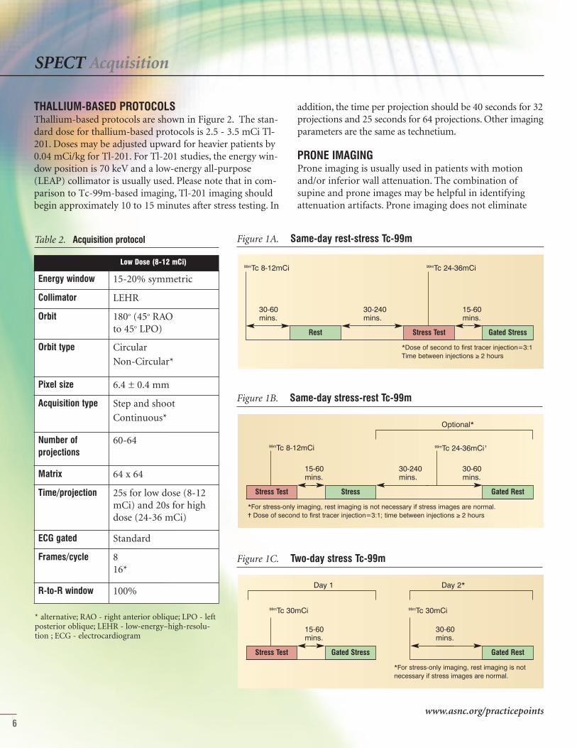
TECHNETIUM-BASED PROTOCOLSProtocols for the various nuclear cardiology single photon-emission computed tomography (SPECT) acquisitionstudies using Anger camera technology and conventional
filtered backprojection reconstruction are presented inTables 1 - 3 as well as in Figure 1. Stress tests should beperformed as per the ASNC Imaging Guidelines for NuclearCardiology Procedures.
SPECT Acquisition
6
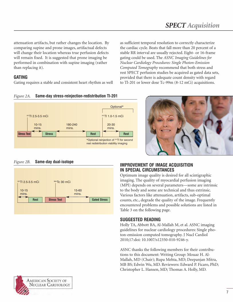
THALLIUM-BASED PROTOCOLSThallium-based protocols are shown in Figure 2. The stan-dard dose for thallium-based protocols is 2.5 - 3.5 mCi Tl-201. Doses may be adjusted upward for heavier patients by0.04 mCi/kg for Tl-201. For Tl-201 studies, the energy win-dow position is 70 keV and a low-energy all-purpose(LEAP) collimator is usually used. Please note that in com-parison to Tc-99m-based imaging, Tl-201 imaging shouldbegin approximately 10 to 15 minutes after stress testing. In
Figure 1C. Two-day stress Tc-99m
Gated StressStress Test Gated Rest
99mTc 30mCi 99mTc 30mCi
30-60 mins.
15-60 mins.
*For stress-only imaging, rest imaging is notnecessary if stress images are normal.
Day 2*Day 1
Energy window 15-20% symmetric
Collimator LEHR
Orbit 180o (45o RAO to 45o LPO)
Orbit type CircularNon-Circular*
Pixel size 6.4 ± 0.4 mm
Acquisition type Step and shootContinuous*
Number of projections
60-64
Matrix 64 x 64
Time/projection 25s for low dose (8-12mCi) and 20s for highdose (24-36 mCi)
ECG gated Standard
Frames/cycle 8 16*
R-to-R window 100%
Table 2. Acquisition protocol
Low Dose (8-12 mCi)
* alternative; RAO - right anterior oblique; LPO - leftposterior oblique; LEHR - low-energy–high-resolu-tion ; ECG - electrocardiogram
Figure 1A. Same-day rest-stress Tc-99m
Rest Stress Test Gated Stress
99mTc 8-12mCi 99mTc 24-36mCi
30-60 mins.
15-60 mins.
30-240 mins.
*Dose of second to first tracer injection=3:1Time between injections ≥ 2 hours
Figure 1B. Same-day stress-rest Tc-99m
StressStress Test Gated Rest
99mTc 8-12mCi 99mTc 24-36mCi ✝
30-60 mins.
15-60 mins.
30-240 mins.
*For stress-only imaging, rest imaging is not necessary if stress images are normal.✝ Dose of second to first tracer injection=3:1; time between injections ≥ 2 hours
Optional*
addition, the time per projection should be 40 seconds for 32projections and 25 seconds for 64 projections. Other imagingparameters are the same as technetium.
PRONE IMAGINGProne imaging is usually used in patients with motionand/or inferior wall attenuation. The combination ofsupine and prone images may be helpful in identifyingattenuation artifacts. Prone imaging does not eliminate
www.asnc.org/practicepoints
IMPROVEMENT OF IMAGE ACQUISITION IN SPECIAL CIRCUMSTANCESOptimum image quality is desired for all scintigraphicimaging. The quality of myocardial perfusion imaging(MPI) depends on several parameters—some are intrinsicto the body and some are technical and thus extrinsic.Various factors like attenuation, artifacts, sub-optimalcounts, etc., degrade the quality of the image. Frequentlyencountered problems and possible solutions are listed inTable 3 on the following page.
SUGGESTED READINGHolly TA, Abbott BA, Al-Mallah M, et al. ASNC imagingguidelines for nuclear cardiology procedures: Single pho-ton-emission computed tomography. J Nucl Cardiol2010;17:doi: 10.1007/s12350-010-9246-y.
ASNC thanks the following members for their contribu-tions to this document: Writing Group: Mouaz H. Al-Mallah, MD (Chair); Rupa Mehta, MD; Deepanjan Mitra,MB BS; Edwin Wu, MD. Reviewers: Edward P. Ficaro, PhD;Christopher L. Hansen, MD; Thomas A. Holly, MD.
SPECT Acquisition
7
Figure 2B. Same-day dual-isotope
Gated StressRest Stress Test
201Tl 2.5-3.5 mCi 99mTc 30 mCi
15-60 mins.
10-15 mins.
attenuation artifacts, but rather changes the location. Bycomparing supine and prone images, artifactual defectswill change their location whereas true perfusion defectswill remain fixed. It is suggested that prone imaging beperformed in combination with supine imaging (ratherthan replacing it).
GATINGGating requires a stable and consistent heart rhythm as well
as sufficient temporal resolution to correctly characterizethe cardiac cycle. Beats that fall more than 20 percent of astable RR interval are usually rejected. Eight- or 16-framegating could be used. The ASNC Imaging Guidelines forNuclear Cardiology Procedures: Single Photon-EmissionComputed Tomography recommend that both stress andrest SPECT perfusion studies be acquired as gated data sets,provided that there is adequate count density with regardto Tl-201 or lower dose Tc-99m (8-12 mCi) acquisitions.
Figure 2A. Same-day stress-reinjection-redistribution Tl-201
Stress RestStress Test Rest
201Tl 2.5-3.5 mCi 201Tl 1.0-1.5 mCi
20-30 mins.
10-15 mins.
180-240 mins.
*Optional reinjection of 201Tl for secondrest redistribution viability imaging
Optional*

SPECT Acquisition
8
High sub-diaphragmatic counts • Adequate exercise• Fatty meal• Optimum delay between acquisition
(minimum 45 minutes for Sestamibiand 30 minutes for Tetrofosmin)
• Consider prone imaging• Repeat imaging
High stomach counts • Check labelling• Give carbonated beverages
• Masking of activity• Repeat acquisition after Metoclopramide
Motion • Proper instruction to the patient• Sufficient delay to recover from the
effects of exercise/stress• Cine mode QC
• If motion is more than one pixel, auto-matic or manual motion correction soft-ware to be used
• Cross checking of sinogram and lino-gram
• Consider prone imaging
Diaphragmaticattenuation/breast attenuation
• Image the patient in the same posi-tion/clothing to avoid shifting breastattenuation
• Consider prone imaging• Attenuation correction by CT
Gating artifacts • Check for arrhythmia• Proper setting of gating histogram
width• Ensure proper voltage of ECG
triggers
• Repeat imaging• Change the ECG leads• Discard gating in cases where there is
count loss/flashing of cine images
Table 3. Frequently encountered problems during SPECT acquisition
PROBLEMS HOW TO AVOID HOW TO CORRECT
QC – quality control; CT – computed tomography; ECG – electrocardiographic
www.asnc.org/practicepoints
FILTERING• The optimal filter for a given image depends on the
signal-to-noise ratio for that image.• Under-filtering an image leaves significant noise in the
image.• Over-filtering unnecessarily blurs image detail.• Both over-filtering and under-filtering can reduce
image accuracy.
REORIENTATION AND DISPLAY• Reorientation is performed either manually or auto-
matically, and results in sectioning the data into verti-cal long-axis, horizontal long-axis, and short-axisplanes.
• Long-axis orientation lines should be parallel to long-axis walls of the myocardium and should be consistentbetween rest and stress studies. Inappropriate plane
selections can result in misalignment between rest andstress data sets, potentially resulting in incorrect inter-pretation.
INTERPRETATIONThe interpretation of myocardial perfusion single photon-emission computed tomography (SPECT) images shouldbe a systematic process which routinely includes: 1. An evaluation of the raw tomographic data in cine
mode for identifying sources of artifact and extracar-diac findings.
9
OVERVIEWIn this document, we will review CardiacSPECT processing and interpretation tech-niques as recommended by the ASNC ImagingGuidelines for Nuclear Cardiology Procedures:Single Photon-Emission ComputedTomography. The implementation of thesesteps is essential in order to provide relevantclinical interpretation that will aid in the man-agement of patients.
IMAGE PROCESSINGDifferent processing tools are available for image recon-struction and filtering. The traditional method of imagereconstruction has been filtered backprojection, whichdoes not correct for photon attenuation, scatter, or colli-mator blurring. The application of a ramp filter amplifiesthe already relatively noisy high-frequency content of theacquired profiles but may result in ramp filter artifact inthe presence of an area of increased tracer uptake nearby(e.g., bowel, papillary muscle).
ITERATIVE RECONSTRUCTIONIterative reconstruction is based upon an initial assump-tion or guess. The guess is refined based on the differencesbetween the generated and actual projections; the processis then repeated usually for a fixed number of iterationsbut can also be repeated until the error between the gener-ated and actual projections is acceptably small. The mainadvantage of iterative reconstruction is that the process ofgenerating projections can incorporate corrections forattenuation, scatter, and collimator-specific, depth-depend-ent blurring. Disadvantages of iterative reconstructioninclude the computational intensity of the algorithmsinvolved (requiring advanced computer technology) andthe potential to introduce data that is not reflective of theraw images.
SPECT Processing and Interpretation
SPECT Processing and Interpretation
10
is normalized to the brightest pixel in the entireimage set.
3. Three-dimensional displays may be useful as adjunctto conventional slice displays.
EVALUATION OF THE IMAGESA review of raw tomographic data in cine mode is essentialfor detecting sources of artifact (e.g., breast and/ordiaphragmatic attenuation, abdominal visceral activity,patient motion). It also may permit the detection of areas
of abnormal extracardiac traceruptake. Intermittent “flashing” ofthe cine gated images suggestsgating error related to arrhyth-mias.
IMAGE ANALYSIS AND INTERPRETATIONIt is recommended that the ini-tial interpretation of the perfu-sion study be performed withoutany clinical information otherthan the patient’s gender, height,and weight to minimize bias instudy interpretation. All relevantclinical data should be reviewedafter a preliminary impression isformed. Each of the followingshould be assessed in the stan-dard interpretation of all SPECTmyocardial perfusion imagingstudies:
1. Ventricular dilation: Left ventricular (LV) enlarge-ment at rest and/or or post-stress should be noted. Stress-to-rest LV cavity ratio,also referred to as transient cavity dilatation (TCD) or transient ischemic dilation
(TID), has been described as a marker for high-riskcoronary disease.
2. Lung uptake: The presence of increased lung uptake after thallium perfusion imaging is an indicator of poor prognosis and should therefore be routinely eval-uated in patients imaged with Tl-201.
2. An evaluation of location, size, severity, and reversibili-ty of perfusion defects; cardiac chamber sizes; andpresence or absence of increased pulmonary uptake(for Tl-201).
3. Review and incorporation of quantitative perfusionanalysis.
4. An evaluation of gated images for global and regionalventricular function.
5. Review and consideration of clinical factors that mayinfluence the final interpretation of the study.
DISPLAY1. It is strongly recommended that the reading physician use
images from the computer monitor screen rather thanhard copies (e.g., paper or film) to interpret the study.
2. Image normalization is optimally performed with“series normalization,” in which the brightest pixel ineach series of images (vertical, horizontal, short axis)
1
2
3
4
5
6
7
8
9 11
10
1213
14
15
1617
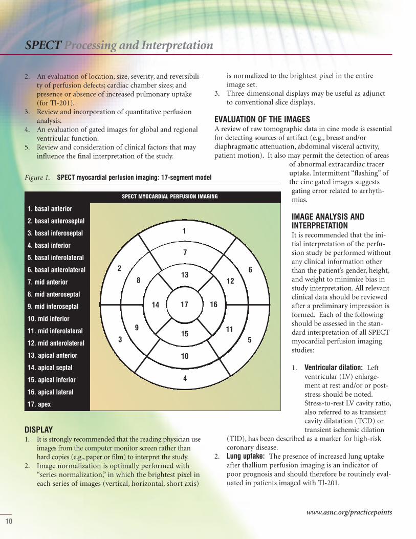
1. basal anterior
2. basal anteroseptal
3. basal inferoseptal
4. basal inferior
5. basal inferolateral
6. basal anterolateral
7. mid anterior
8. mid anteroseptal
9. mid inferoseptal
10. mid inferior
11. mid inferolateral
12. mid anterolateral
13. apical anterior
14. apical septal
15. apical inferior
16. apical lateral
17. apex
Figure 1. SPECT myocardial perfusion imaging: 17-segment model
SPECT MYOCARDIAL PERFUSION IMAGING
www.asnc.org/practicepoints
SPECT Processing and Interpretation
11
3. Right ventricular (RV) uptake and RV dilation: RVuptake and RV dilation may be qualitatively assessed onthe raw projection data and on the reconstructed data.The intensity of the right ventricle is normal approxi-mately 50 percent of peak LV intensity.
4. Non-cardiac findings: Both thallium- and technetium-based agents can be concentrated in tumors, anduptake outside the myocardium may reflect unexpect-ed pathology.
5. Perfusion defects: Myocardial perfusion defectsshould be identified by visual analysis of the recon-structed slices. The perfusion defects should be charac-terized by their location as they relate to specificmyocardial walls using the 17-segment model (Figure1). Defect severity is typically expressed qualitativelyas mild, moderate, or severe. Defect extent may bequalitatively described as small, medium, or large.Defects whose severity and extent do not changebetween stress and rest images are categorized as“fixed” or “nonreversible.” When perfusion defects aremore severe and/or extensive on stress compared torest images, a qualitative description of the degree ofreversibility is required.
6. Semiquantitative analysis: The use of a semiquantita-tive segmental scoring system standardizes the visualinterpretation of scans, reduces the likelihood of over-looking significant defects, and provides an importantindex that is applicable to diagnostic and prognosticassessments. However, the accuracy of these scores ishighly dependent upon how the initial images aresetup for processing. The 17-segment, five-point scor-ing system (Table 1) is recommended. In addition to
Normal perfusion 0
Mild reduction in counts — not definitely abnormal
1
Moderate reduction in counts — definitely abnormal
2
Severe reduction in counts 3
Absent uptake 4
Table 1. The Five-Point Model
Category Score
individual scores, summed stress scores (SSS), summedrest scores (SRS), and summed difference score (SDS)should be calculated. Ischemia on scans is categorizedas mild when the SDS is 1 to 3, moderate when theSDS is 4 to 7, or severe when the SDS is greater than 7.
7. Gated SPECT — regional wall motion and thickening:Regional wall motion should be analyzed using a stan-dard nomenclature: normal, hypokinesis, akinesis, anddyskinesis. Hypokinesis may be further qualified as

mild, moderate, or severe. A semiquantitative scoringsystem is recommended where 0 is normal, 1 is mildhypokinesis, 2 is moderate hypokinesis, 3 is severehypokinesis, 4 is akinesis, and 5 is dyskinesis.
8. Left ventricular ejection fraction (LVEF) and volume:Quantitative evaluation of LVEF should be done andreported. LVEF may be categorized as normal, mildly,moderately, or severely reduced. Left ventricle cham-ber sizes as well as end-diastolic and end-systolic vol-umes should routinely be evaluated qualitatively andquantitatively.
INTEGRATION OF PERFUSION AND FUNCTIONRESULTS 1. The results of the perfusion and gated SPECT data sets
should be integrated into a final interpretation. 2. The wall motion is particularly helpful in distinguish-
ing nonreversible (fixed) perfusion defects due to priormyocardial infarction from nonreversible defects dueto attenuation artifacts.
3. Fixed perfusion defects that do not show a correspon-ding abnormality of wall motion or myocardial sys-tolic thickening are more likely to be due to artifacts.
MODIFICATION OF INTERPRETATION BY RELEVANTCLINICAL INFORMATION • It is important to keep in mind the majority of arti-
facts encountered will produce mild defects.• When uncertainty exists, it is helpful to incorporate
clinical information (e.g., symptoms, risk factors, ST-segment changes, exercise tolerance) to help the refer-ring physician make the most appropriate manage-ment decisions for the patient.
• Markers of severe ischemia, such as marked ST-seg-ment changes, increased stress:rest LV cavity ratio
SPECT Processing and Interpretation
(transient ischemic dilation), or increased lung uptake(particularly with thallium) should be used to identifythose patients with balanced ischemia due to multi-vessel coronary artery disease.
REPORTING A detailed description of SPECT reporting is described inthe ASNC Imaging Guidelines for Nuclear CardiologyProcedures: Reporting of Radionuclide Myocardial Perfusionand Function as well as the ASNC Practice Points: Reportingof Myocardial Perfusion Imaging Tests.
SUGGESTED READING Holly TA, Abbott BA, Al-Mallah M, et al. ASNC imagingguidelines for nuclear cardiology procedures: Single pho-ton-emission computed tomography. J Nucl Cardiol2010;17:doi: 10.1007/s12350-010-9246-y.
Tilkemeier PL, Cooke CD, Grossman GB, et al. ASNCimaging guidelines for nuclear cardiology procedures:Standardized reporting of radionuclide myocardial perfusion and function. J Nucl Cardiol 2009;16:doi:10.1007/s12350-009-9095-8.
ASNC thanks the following members for their contributions to this document: Writing Group: Mouaz H.Al-Mallah, MD (Chair); Regina Druz, MD; ShawnGregory, MD; R. Parker Ward, MD. Reviewers: Edward P.Ficaro, PhD; Christopher L. Hansen, MD; Thomas A.Holly, MD
12
The 2011 Practice Points program is supported by AstellasPharma US, Inc., Bracco Diagnostics Inc., Covidien-Mallinckrodt,GE Healthcare, and Lantheus Medical Imaging.
American Society of Nuclear Cardiology4340 East-West Highway, Suite 1120Bethesda, MD 20814-4578www.asnc.org
Last updated: August 2011
www.asnc.org/practicepoints