spectra 30 pattern controller, 1123406 - welcome to...
TRANSCRIPT
Spectra 30 Pattern ControllerCustomer Product Manual
Part 1123406_01Issued 8/14
NORDSON CORPORATION DULUTH, GEORGIA USAwww.nordson.com
This document contains important safety informationBe sure to read and follow all safety information in thisdocument and any other related documentation.

Part 1123406_01 E 08/2014 Nordson CorporationAll rights reserved
Nordson Corporation welcomes requests for information, comments, and inquiries about its products. General informationabout Nordson can be found on the Internet using the following address: http://www.nordson.com.
Address all correspondence to:
Nordson CorporationAttn: Customer Service11475 Lakefield DriveDuluth, GA 30097
Notice
This is a Nordson Corporation publication which is protected by copyright. Original copyright date 2014.No part of this document may be photocopied, reproduced, or translated to another language without the prior writtenconsent of Nordson Corporation. The information contained in this publication is subject to change without notice.
Trademarks
AccuJet, AeroCharge, Apogee, AquaGuard, Asymtek, Automove, Baitgun, Blue Box, Bowtie, Build-A-Part, CanWorks, Century, CF, CleanSleeve,CleanSpray, ColorMax, Color-on-Demand, Control Coat, Coolwave, Cross-Cut, cScan+, Dage, Dispensejet, DispenseMate, DuraBlue, DuraDrum, Durafiber,
DuraPail, Dura-Screen, Durasystem, Easy Coat, Easymove Plus, Ecodry, Econo-Coat, e.DOT, EFD, Emerald, Encore, ESP, e stylized, ETI-stylized,Excel 2000, Fibrijet, Fillmaster, FlexiCoat, Flex-O-Coat, Flow Sentry, Fluidmove, FoamMelt, FoamMix, Fulfill, GreenUV, HDLV, Heli-flow, Horizon, Hot Shot,
iControl, iDry, iFlow, Isocoil, Isocore, Iso-Flo, iTRAX, Kinetix, KISS, Lean Cell, Little Squirt, LogiComm, Magnastatic, March, Maverick, MEG, Meltex,Microcoat, Micromark, Micromedics, Micro-Meter, MicroSet, Millennium, MiniBlue, Mini Squirt, Mountaingate, NexJet, No-Drip, Nordson, Optimum,
Package of Values, Paragon, Pattern View, PermaFlo, PICO, PicoDot, Porous Coat, PowderGrid, Powderware, Precisecoat, Printplus, Prism, ProBlue,Prodigy, Pro-Flo, Program-A-Bead, Program-A-Shot, Program-A-Stream, Program-A-Swirl, ProLink, Pro-Meter, Pro-Stream, RBX, Rhino, Saturn,
Saturn with rings, Scoreguard, Sealant Equipment & Engineering, Inc, SEE and design, See-Flo, Seal Sentry, Select Charge, Select Coat, Select Cure,Servo-Flo, Shot-A-Matic, Signature, Slautterback, Smart-Coat, Solder Plus, Spectrum, Speed-Coat, SureBead, Sure Coat, Sure-Max, Sure Wrap,Tracking Plus, TRAK, Trends, Tribomatic, TrueBlue, TrueCoat, Tubesetter, Ultra, UpTime, u-TAH, Value Plastics, Vantage, VersaBlue, Versa-Coat,
VersaDrum, VersaPail, Versa-Screen, Versa-Spray,VP Quick Fit, Watermark, When you expect more., and X-Planeare registered trademarks of Nordson Corporation.
Accubar, Active Nozzle, Advanced Plasma Systems, AeroDeck, AeroWash, Allegro, AltaBlue, AltaSlot, Alta Spray, Artiste, ATS, Auto-Flo, AutoScan, Axiom,Best Choice, Blue Series, Bravura, CanPro, Champion, Check Mate, ClassicBlue, Classic IX, Clean Coat, Cobalt, Controlled Fiberization, Control Weave,
ContourCoat, CPX, cSelect, Cyclo-Kinetic, DispensLink, Dry Cure, DuraBraid, DuraCoat, DuraPUR, Easy Clean, EasyOn, EasyPW, Eclipse, e.dot+,E-Nordson, Equalizer, EquiBead, FillEasy, Fill Sentry, Flow Coat, Fluxplus, Freedom, Get Green With Blue, G-Net, Genius, G-Site, IntelliJet, iON, Iso-Flex,iTrend, Lacquer Cure, Maxima, Mesa, MicroFin, MicroMax, Mikros, MiniEdge, Minimeter, Multifill, MultiScan, Myritex, Nano, OmniScan, OptiMix, OptiStroke,Optix, Partnership+Plus, PatternJet, PatternPro, PCI, PharmaLok, Pinnacle, Plasmod, Powder Pilot, Powder Port, Powercure, Process Sentry, Pulse Spray,PURBlue, PURJet, Ready Coat, RediCoat, RollVIA, Quantum, Royal Blue, Select Series, Sensomatic, Shaftshield, SheetAire, Smart, Smartfil, SolidBlue,Spectral, SpeedKing, Spray Works, StediFlo, StediTherm, Summit, SureFoam, Sure Mix, SureSeal, Swirl Coat, TAH, ThruWave, Trade Plus, Trilogy,
Ultra FoamMix, UltraMax, Ultrasaver, Ultrasmart, Universal, ValueMate, Versa, Vista, Web Cure, YESTECH, and 2 Rings (Design)are trademarks of Nordson Corporation.
Designations and trademarks stated in this document may be brands that, when used by third parties for their own purposes,could lead to violation of the owners' rights.

Table of Contents i
Part 1123406_01E 08/2014 Nordson Corporation
Table of ContentsSafety 1-1. . . . . . . . . . . . . . . . . . . . . . . . . . . . . . . . . . . . . . . . . . . . . . . . . . . . .Safety Alert Symbols 1-1. . . . . . . . . . . . . . . . . . . . . . . . . . . . . . . . . . . . . . . .Responsibilities of the Equipment Owner 1-2. . . . . . . . . . . . . . . . . . . . . . .
Safety Information 1-2. . . . . . . . . . . . . . . . . . . . . . . . . . . . . . . . . . . . . . . .Instructions, Requirements, and Standards 1-2. . . . . . . . . . . . . . . . . .User Qualifications 1-3. . . . . . . . . . . . . . . . . . . . . . . . . . . . . . . . . . . . . . .
Applicable Industry Safety Practices 1-3. . . . . . . . . . . . . . . . . . . . . . . . . .Intended Use of the Equipment 1-3. . . . . . . . . . . . . . . . . . . . . . . . . . . . .Instructions and Safety Messages 1-4. . . . . . . . . . . . . . . . . . . . . . . . . .Installation Practices 1-4. . . . . . . . . . . . . . . . . . . . . . . . . . . . . . . . . . . . . .Operating Practices 1-4. . . . . . . . . . . . . . . . . . . . . . . . . . . . . . . . . . . . . .Maintenance and Repair Practices 1-5. . . . . . . . . . . . . . . . . . . . . . . . .
Equipment Safety Information 1-5. . . . . . . . . . . . . . . . . . . . . . . . . . . . . . . .Equipment Shutdown 1-6. . . . . . . . . . . . . . . . . . . . . . . . . . . . . . . . . . . . .
Relieving System Hydraulic Pressure 1-6. . . . . . . . . . . . . . . . . . . . .De-energizing the System 1-6. . . . . . . . . . . . . . . . . . . . . . . . . . . . . . .Disabling the Applicators 1-6. . . . . . . . . . . . . . . . . . . . . . . . . . . . . . . .
General Safety Warnings and Cautions 1-7. . . . . . . . . . . . . . . . . . . . . .Other Safety Precautions 1-10. . . . . . . . . . . . . . . . . . . . . . . . . . . . . . . . . .First Aid 1-10. . . . . . . . . . . . . . . . . . . . . . . . . . . . . . . . . . . . . . . . . . . . . . . . .
Safety Label and Tag 1-11. . . . . . . . . . . . . . . . . . . . . . . . . . . . . . . . . . . . . . .
Overview 2-1. . . . . . . . . . . . . . . . . . . . . . . . . . . . . . . . . . . . . . . . . . . . . . . . . .Getting to Know Spectra 30 2-1. . . . . . . . . . . . . . . . . . . . . . . . . . . . . . . . . .
Spectra 30 Pattern Controller and Components 2-2. . . . . . . . . . . . . . .Standard Components 2-3. . . . . . . . . . . . . . . . . . . . . . . . . . . . . . . . . . . .Add-on Features 2-3. . . . . . . . . . . . . . . . . . . . . . . . . . . . . . . . . . . . . . . .
Comparison Table 2-4. . . . . . . . . . . . . . . . . . . . . . . . . . . . . . . . . . . . .Front Panel 2-5. . . . . . . . . . . . . . . . . . . . . . . . . . . . . . . . . . . . . . . . . . . . . .Base Panel 2-6. . . . . . . . . . . . . . . . . . . . . . . . . . . . . . . . . . . . . . . . . . . . . .
Other Sources of Information 2-8. . . . . . . . . . . . . . . . . . . . . . . . . . . . . . . . .Quick Reference Guide 2-8. . . . . . . . . . . . . . . . . . . . . . . . . . . . . . . . . . .Installation Guide 2-8. . . . . . . . . . . . . . . . . . . . . . . . . . . . . . . . . . . . . . . . .Product Manual 2-8. . . . . . . . . . . . . . . . . . . . . . . . . . . . . . . . . . . . . . . . . .Software Update / Online Support 2-8. . . . . . . . . . . . . . . . . . . . . . . . . .
Advanced Setting Utility 2-8. . . . . . . . . . . . . . . . . . . . . . . . . . . . . . . . .
Table of Contentsii
Part 1123406_01 E 08/2014 Nordson Corporation
Installation 3-1. . . . . . . . . . . . . . . . . . . . . . . . . . . . . . . . . . . . . . . . . . . . . . . .Mount the Spectra 30 3-1. . . . . . . . . . . . . . . . . . . . . . . . . . . . . . . . . . . . . . .
Unpacking 3-1. . . . . . . . . . . . . . . . . . . . . . . . . . . . . . . . . . . . . . . . . . . . .Guidelines 3-1. . . . . . . . . . . . . . . . . . . . . . . . . . . . . . . . . . . . . . . . . . . . . .Dimensions 3-2. . . . . . . . . . . . . . . . . . . . . . . . . . . . . . . . . . . . . . . . . . . . .Mounting the Pattern Controller 3-3. . . . . . . . . . . . . . . . . . . . . . . . . . . . .
Connect the Spectra 30 3-5. . . . . . . . . . . . . . . . . . . . . . . . . . . . . . . . . . . . .Internal Wiring Details 3-7. . . . . . . . . . . . . . . . . . . . . . . . . . . . . . . . . . . .Important Wiring Details 3-8. . . . . . . . . . . . . . . . . . . . . . . . . . . . . . . . . . .
To Insert Wires in Terminal Blocks 3-8. . . . . . . . . . . . . . . . . . . . . . . .To Remove Wires from Terminal Blocks 3-8. . . . . . . . . . . . . . . . . . .Wire Gauge Range 3-8. . . . . . . . . . . . . . . . . . . . . . . . . . . . . . . . . . . . .
Before Setting Up Spectra 30 3-9. . . . . . . . . . . . . . . . . . . . . . . . . . . . . . . .
The User Interface 4-1. . . . . . . . . . . . . . . . . . . . . . . . . . . . . . . . . . . . . . . . .Screen Navigation 4-1. . . . . . . . . . . . . . . . . . . . . . . . . . . . . . . . . . . . . . . . . .
Home Screen Touch Area 4-2. . . . . . . . . . . . . . . . . . . . . . . . . . . . . . . . .Start Spectra 30 4-3. . . . . . . . . . . . . . . . . . . . . . . . . . . . . . . . . . . . . . . . . . . .
Setup Wizard 4-3. . . . . . . . . . . . . . . . . . . . . . . . . . . . . . . . . . . . . . . . . . . .About the Splash Screen 4-6. . . . . . . . . . . . . . . . . . . . . . . . . . . . . . . . . . . .
Add-on Features 4-6. . . . . . . . . . . . . . . . . . . . . . . . . . . . . . . . . . . . . . . . .About the Home Screen 4-7. . . . . . . . . . . . . . . . . . . . . . . . . . . . . . . . . . . . .
Status Bar Components 4-9. . . . . . . . . . . . . . . . . . . . . . . . . . . . . . . . . . .Using the Home Screen 4-12. . . . . . . . . . . . . . . . . . . . . . . . . . . . . . . . . . . . .
What you can do from the Home Screen 4-13. . . . . . . . . . . . . . . . . . . . .Pattern Programming 4-15. . . . . . . . . . . . . . . . . . . . . . . . . . . . . . . . . . . . . . .
Normal Pattern 4-17. . . . . . . . . . . . . . . . . . . . . . . . . . . . . . . . . . . . . . . . .Other Pattern Types 4-19. . . . . . . . . . . . . . . . . . . . . . . . . . . . . . . . . . . . . .
EcoBead Pattern 4-19. . . . . . . . . . . . . . . . . . . . . . . . . . . . . . . . . . . . . . .Dot Pattern 4-22. . . . . . . . . . . . . . . . . . . . . . . . . . . . . . . . . . . . . . . . . . .Random Bead Length 4-24. . . . . . . . . . . . . . . . . . . . . . . . . . . . . . . . . . .Random Mirror Mode Pattern 4-26. . . . . . . . . . . . . . . . . . . . . . . . . . . .
Applicator Channel Settings 4-28. . . . . . . . . . . . . . . . . . . . . . . . . . . . . . . . . .Trigger Settings 4-31. . . . . . . . . . . . . . . . . . . . . . . . . . . . . . . . . . . . . . . . . . . .Select Recipes 4-33. . . . . . . . . . . . . . . . . . . . . . . . . . . . . . . . . . . . . . . . . . . . .
Using the Menus 5-1. . . . . . . . . . . . . . . . . . . . . . . . . . . . . . . . . . . . . . . . . .Overview 5-1. . . . . . . . . . . . . . . . . . . . . . . . . . . . . . . . . . . . . . . . . . . . . . . . . .
What you can do from the Main Menu 5-2. . . . . . . . . . . . . . . . . . . . . .Purge Applicators 5-4. . . . . . . . . . . . . . . . . . . . . . . . . . . . . . . . . . . . . . . .Manage Recipes 5-6. . . . . . . . . . . . . . . . . . . . . . . . . . . . . . . . . . . . . . . . .
Recipe Quick Change 5-7. . . . . . . . . . . . . . . . . . . . . . . . . . . . . . . . . .Manage Recipe Files 5-9. . . . . . . . . . . . . . . . . . . . . . . . . . . . . . . . . . .What's Being Saved in a Recipe File 5-13. . . . . . . . . . . . . . . . . . . . . .Recipe Mismatches 5-13. . . . . . . . . . . . . . . . . . . . . . . . . . . . . . . . . . . .Remote Control Recipe Selection 5-15. . . . . . . . . . . . . . . . . . . . . . . . .
Password Lock/Unlock 5-16. . . . . . . . . . . . . . . . . . . . . . . . . . . . . . . . . . .Pressure Run-up 5-17. . . . . . . . . . . . . . . . . . . . . . . . . . . . . . . . . . . . . . . . .
Tools Menu 5-18. . . . . . . . . . . . . . . . . . . . . . . . . . . . . . . . . . . . . . . . . . . . . . . .Tools Menu Screens 5-19. . . . . . . . . . . . . . . . . . . . . . . . . . . . . . . . . . . . .
System Settings 5-30. . . . . . . . . . . . . . . . . . . . . . . . . . . . . . . . . . . . . . . . . . . .System Setup Screens 5-31. . . . . . . . . . . . . . . . . . . . . . . . . . . . . . . . . . .

Table of Contents iii
Part 1123406_01E 08/2014 Nordson Corporation
Troubleshooting 6-1. . . . . . . . . . . . . . . . . . . . . . . . . . . . . . . . . . . . . . . . . . .Diagnostics Tools 6-2. . . . . . . . . . . . . . . . . . . . . . . . . . . . . . . . . . . . . . . . . .
System Status 6-2. . . . . . . . . . . . . . . . . . . . . . . . . . . . . . . . . . . . . . . . . . .Diagnostic Status Symbols 6-3. . . . . . . . . . . . . . . . . . . . . . . . . . . . . . . .Component Diagnostic Symbols 6-3. . . . . . . . . . . . . . . . . . . . . . . . . . .
Applicator Symbols 6-3. . . . . . . . . . . . . . . . . . . . . . . . . . . . . . . . . . . .Trigger Symbols 6-4. . . . . . . . . . . . . . . . . . . . . . . . . . . . . . . . . . . . . . .Pattern Alerts 6-4. . . . . . . . . . . . . . . . . . . . . . . . . . . . . . . . . . . . . . . . .
Message Log 6-5. . . . . . . . . . . . . . . . . . . . . . . . . . . . . . . . . . . . . . . . . . . . . .Message Text 6-5. . . . . . . . . . . . . . . . . . . . . . . . . . . . . . . . . . . . . . . . . . .Message Scroll Indicator 6-6. . . . . . . . . . . . . . . . . . . . . . . . . . . . . . . . . .Message Status Indicators 6-6. . . . . . . . . . . . . . . . . . . . . . . . . . . . . . . . .Resolving Alerts and Faults 6-7. . . . . . . . . . . . . . . . . . . . . . . . . . . . . . . .Shortcut Buttons 6-7. . . . . . . . . . . . . . . . . . . . . . . . . . . . . . . . . . . . . . . . .
System Self-Test 6-8. . . . . . . . . . . . . . . . . . . . . . . . . . . . . . . . . . . . . . . . . . .System Outputs 6-10. . . . . . . . . . . . . . . . . . . . . . . . . . . . . . . . . . . . . . . . . . . .
System Status Summary Chart 6-11. . . . . . . . . . . . . . . . . . . . . . . . . . . . .Defining the System Statuses 6-12. . . . . . . . . . . . . . . . . . . . . . . . . . .
When the System Fails to Start Up 6-14. . . . . . . . . . . . . . . . . . . . . . . . . . . .Controller Board Issues 6-14. . . . . . . . . . . . . . . . . . . . . . . . . . . . . . . . . . .Power Supply Board 6-16. . . . . . . . . . . . . . . . . . . . . . . . . . . . . . . . . . . . . .Touch Screen Issues 6-17. . . . . . . . . . . . . . . . . . . . . . . . . . . . . . . . . . . . .Ethernet Network Communications Issues 6-19. . . . . . . . . . . . . . . . . . .Calibration Screen 6-20. . . . . . . . . . . . . . . . . . . . . . . . . . . . . . . . . . . . . . . .
Specifications 7-1. . . . . . . . . . . . . . . . . . . . . . . . . . . . . . . . . . . . . . . . . . . . .System Specifications 7-1. . . . . . . . . . . . . . . . . . . . . . . . . . . . . . . . . . . .Encoder 7-1. . . . . . . . . . . . . . . . . . . . . . . . . . . . . . . . . . . . . . . . . . . . . . . .
Distance and Time Based Pattern Controller 7-1. . . . . . . . . . . . . . .Interface 7-2. . . . . . . . . . . . . . . . . . . . . . . . . . . . . . . . . . . . . . . . . . . . . . . .Inputs/Outputs 7-2. . . . . . . . . . . . . . . . . . . . . . . . . . . . . . . . . . . . . . . . . . .Enclosure 7-2. . . . . . . . . . . . . . . . . . . . . . . . . . . . . . . . . . . . . . . . . . . . . . .Patterns and Recipes 7-3. . . . . . . . . . . . . . . . . . . . . . . . . . . . . . . . . . . . .Applicators 7-3. . . . . . . . . . . . . . . . . . . . . . . . . . . . . . . . . . . . . . . . . . . . . .Triggers 7-4. . . . . . . . . . . . . . . . . . . . . . . . . . . . . . . . . . . . . . . . . . . . . . . .Pressure Run-up 7-4. . . . . . . . . . . . . . . . . . . . . . . . . . . . . . . . . . . . . . . . .Diagnostics 7-5. . . . . . . . . . . . . . . . . . . . . . . . . . . . . . . . . . . . . . . . . . . . .Software License 7-5. . . . . . . . . . . . . . . . . . . . . . . . . . . . . . . . . . . . . . . . .
System Schematic 7-6. . . . . . . . . . . . . . . . . . . . . . . . . . . . . . . . . . . . . . . . . .
Parts 8-1. . . . . . . . . . . . . . . . . . . . . . . . . . . . . . . . . . . . . . . . . . . . . . . . . . . . . .Spectra 30 Pattern Controller Parts List 8-1. . . . . . . . . . . . . . . . . . . . . . . .
Pattern Controller 8-1. . . . . . . . . . . . . . . . . . . . . . . . . . . . . . . . . . . . . . . .Software License 8-1. . . . . . . . . . . . . . . . . . . . . . . . . . . . . . . . . . . . . . . .Ship-with Kit 8-1. . . . . . . . . . . . . . . . . . . . . . . . . . . . . . . . . . . . . . . . . . . .Service Kits 8-2. . . . . . . . . . . . . . . . . . . . . . . . . . . . . . . . . . . . . . . . . . . . .Add-on Features Parts List 8-3. . . . . . . . . . . . . . . . . . . . . . . . . . . . . . . .

Table of Contentsiv
Part 1123406_01 E 08/2014 Nordson Corporation

Safety 1-1
E 08/2014 Nordson Corporation Issued 10-11
Section 1Safety
Read this section before using the equipment. This section containsrecommendations and practices applicable to the safe installation, operation,and maintenance (hereafter referred to as “use”) of the product described inthis document (hereafter referred to as “equipment”). Additional safetyinformation, in the form of task-specific safety alert messages, appears asappropriate throughout this document.
WARNING! Failure to follow the safety messages, recommendations, andhazard avoidance procedures provided in this document can result inpersonal injury, including death, or damage to equipment or property.
Safety Alert SymbolsThe following safety alert symbol and signal words are used throughout thisdocument to alert the reader to personal safety hazards or to identifyconditions that may result in damage to equipment or property. Comply withall safety information that follows the signal word.
WARNING! Indicates a potentially hazardous situation that, if not avoided,can result in serious personal injury, including death.
CAUTION! Indicates a potentially hazardous situation that, if not avoided,can result in minor or moderate personal injury.
CAUTION! (Used without the safety alert symbol) Indicates a potentiallyhazardous situation that, if not avoided, can result in damage to equipment orproperty.

Safety1-2
E 08/2014 Nordson CorporationIssued 10- 11
Responsibilities of the Equipment OwnerEquipment owners are responsible for managing safety information, ensuringthat all instructions and regulatory requirements for use of the equipment aremet, and for qualifying all potential users.
Safety InformationS Research and evaluate safety information from all applicable sources,
including the owner-specific safety policy, best industry practices,governing regulations, material manufacturer's product information, andthis document.
S Make safety information available to equipment users in accordance withgoverning regulations. Contact the authority having jurisdiction forinformation.
S Maintain safety information, including the safety labels affixed to theequipment, in readable condition.
Instructions, Requirements, and StandardsS Ensure that the equipment is used in accordance with the information
provided in this document, governing codes and regulations, and bestindustry practices.
S If applicable, receive approval from your facility's engineering or safetydepartment, or other similar function within your organization, beforeinstalling or operating the equipment for the first time.
S Provide appropriate emergency and first aid equipment.S Conduct safety inspections to ensure required practices are being
followed.S Re-evaluate safety practices and procedures whenever changes are
made to the process or equipment.
Safety 1-3
E 08/2014 Nordson Corporation Issued 10-11
User QualificationsEquipment owners are responsible for ensuring that users:S receive safety training appropriate to their job function as directed by
governing regulations and best industry practicesS are familiar with the equipment owner's safety and accident
prevention policies and proceduresS receive equipment- and task-specific training from another qualified
individualNOTE: Nordson can provide equipment-specific installation,operation, and maintenance training. Contact your Nordsonrepresentative for information
S possess industry- and trade-specific skills and a level of experienceappropriate to their job function
S are physically capable of performing their job function and are notunder the influence of any substance that degrades their mentalcapacity or physical capabilities
Applicable Industry Safety PracticesThe following safety practices apply to the use of the equipment in themanner described in this document. The information provided here is notmeant to include all possible safety practices, but represents the best safetypractices for equipment of similar hazard potential used in similar industries.
Intended Use of the EquipmentS Use the equipment only for the purposes described and within the limits
specified in this document.S Do not modify the equipment.S Do not use incompatible materials or unapproved auxiliary devices.
Contact your Nordson representative if you have any questions onmaterial compatibility or the use of non-standard auxiliary devices.
Safety1-4
E 08/2014 Nordson CorporationIssued 10- 11
Instructions and Safety MessagesS Read and follow the instructions provided in this document and other
referenced documents.S Familiarize yourself with the location and meaning of the safety warning
labels and tags affixed to the equipment. Refer to Safety Labels and Tagsat the end of this section.
S If you are unsure of how to use the equipment, contact your Nordsonrepresentative for assistance.
Installation PracticesS Install the equipment in accordance with the instructions provided in this
document and in the documentation provided with auxiliary devices.S Ensure that the equipment is rated for the environment in which it will be
used. This equipment has not been certified for compliance with theATEX directive nor as nonincendive and should not be installed inpotentially explosive environments.
S Ensure that the processing characteristics of the material will not create ahazardous environment. Refer to the Material Safety Data Sheet (MSDS)for the material.
S If the required installation configuration does not match the installationinstructions, contact your Nordson representative for assistance.
S Position the equipment for safe operation. Observe the requirements forclearance between the equipment and other objects.
S Install lockable power disconnects to isolate the equipment and allindependently powered auxiliary devices from their power sources.
S Properly ground all equipment. Contact your local building codeenforcement agency for specific requirements.
S Ensure that fuses of the correct type and rating are installed in fusedequipment.
S Contact the authority having jurisdiction to determine the requirement forinstallation permits or inspections.
Operating PracticesS Familiarize yourself with the location and operation of all safety devices
and indicators.S Confirm that the equipment, including all safety devices (guards,
interlocks, etc.), is in good working order and that the requiredenvironmental conditions exist.
S Use the personal protective equipment (PPE) specified for each task.Refer to Equipment Safety Information or the material manufacturer'sinstructions and MSDS for PPE requirements.
S Do not use equipment that is malfunctioning or shows signs of a potentialmalfunction.

Safety 1-5
E 08/2014 Nordson Corporation Issued 10-11
Maintenance and Repair PracticesS Allow only personnel with appropriate training and experience to operate
or service the equipment.S Perform scheduled maintenance activities at the intervals described in
this document.S Relieve system hydraulic and pneumatic pressure before servicing the
equipment.S De-energize the equipment and all auxiliary devices before servicing the
equipment.S Use only new Nordson-authorized refurbished or replacement parts.S Read and comply with the manufacturer's instructions and the MSDS
supplied with equipment cleaning compounds.NOTE: MSDSs for cleaning compounds that are sold by Nordson areavailable at www.nordson.com or by calling your Nordson representative.
S Confirm the correct operation of all safety devices before placing theequipment back into operation.
S Dispose of waste cleaning compounds and residual process materialsaccording to governing regulations. Refer to the applicable MSDS orcontact the authority having jurisdiction for information.
S Keep equipment safety warning labels clean. Replace worn or damagedlabels.
Equipment Safety InformationThis equipment safety information is applicable to the following types ofNordson equipment:S hot melt and cold adhesive application equipment and all related
accessoriesS pattern controllers, timers, detection and verification systems, and all
other optional process control devices

Safety1-6
E 08/2014 Nordson CorporationIssued 10- 11
Equipment ShutdownTo safely complete many of the procedures described in this document, theequipment must first be shut down. The level of shut down required varies bythe type of equipment in use and the procedure being completed.If required, shut down instructions are specified at the start of the procedure.The levels of shut down are:
Relieving System Hydraulic PressureCompletely relieve system hydraulic pressure before breaking any hydraulicconnection or seal. Refer to the melter-specific product manual forinstructions on relieving system hydraulic pressure.
De-energizing the SystemIsolate the system (melter, hoses, applicators, and optional devices) from allpower sources before accessing any unprotected high-voltage wiring orconnection point.1.. Turn off the equipment and all auxiliary devices connected to the
equipment (system).2.. To prevent the equipment from being accidentally energized, lock and
tag the disconnect switch(es) or circuit breaker(s) that provide inputelectrical power to the equipment and optional devices.NOTE: Government regulations and industry standards dictate specificrequirements for the isolation of hazardous energy sources. Refer to theappropriate regulation or standard.
Disabling the ApplicatorsNOTE: Adhesive dispensing applicators are referred to as “guns” in someprevious publications.All electrical or mechanical devices that provide an activation signal to theapplicators, applicator solenoid valve(s), or the melter pump must bedisabled before work can be performed on or around an applicator that isconnected to a pressurized system.1.. Turn off or disconnect the applicator triggering device (pattern controller,
timer, PLC, etc.).2.. Disconnect the input signal wiring to the applicator solenoid valve(s).3.. Reduce the air pressure to the applicator solenoid valve(s) to zero; then
relieve the residual air pressure between the regulator and the applicator.

Safety 1-7
E 08/2014 Nordson Corporation Issued 10-11
General Safety Warnings and CautionsTable 1-1 contains the general safety warnings and cautions that apply toNordson hot melt and cold adhesive equipment. Review the table andcarefully read all of the warnings or cautions that apply to the type ofequipment described in this manual.
Equipment types are designated in Table 1-1 as follows:HM = Hot melt (melters, hoses, applicators, etc.)PC = Process controlCA = Cold adhesive (dispensing pumps, pressurized container, andapplicators)
Table 1-1General Safety Warnings and CautionsEquipment
Type Warning or Caution
HM
WARNING! Hazardous vapors! Before processing any polyurethanereactive (PUR) hot melt or solvent-based material through a compatibleNordson melter, read and comply with the material's MSDS. Ensurethat the material's processing temperature and flashpoints will not beexceeded and that all requirements for safe handling, ventilation, firstaid, and personal protective equipment are met. Failure to comply withMSDS requirements can cause personal injury, including death.
HM
WARNING! Reactive material! Never clean any aluminum componentor flush Nordson equipment with halogenated hydrocarbon fluids.Nordson melters and applicators contain aluminum components thatmay react violently with halogenated hydrocarbons. The use ofhalogenated hydrocarbon compounds in Nordson equipment cancause personal injury, including death.
HM, CAWARNING! System pressurized! Relieve system hydraulic pressurebefore breaking any hydraulic connection or seal. Failure to relieve thesystem hydraulic pressure can result in the uncontrolled release of hotmelt or cold adhesive, causing personal injury.
Continued...

Safety1-8
E 08/2014 Nordson CorporationIssued 10- 11
Table 1-1General Safety Warnings and Cautions (contd)Equipment
Type Warning or Caution
HMWARNING! Molten material! Wear eye or face protection, clothing thatprotects exposed skin, and heat-protective gloves when servicingequipment that contains molten hot melt. Even when solidified, hot meltcan still cause burns. Failure to wear appropriate personal protectiveequipment can result in personal injury.
HM, PC
WARNING! Equipment starts automatically! Remote triggering devicesare used to control automatic hot melt applicators. Before working onor near an operating applicator, disable the applicator's triggeringdevice and remove the air supply to the applicator's solenoid valve(s).Failure to disable the applicator's triggering device and remove thesupply of air to the solenoid valve(s) can result in personal injury.
HM, CA, PC
WARNING! Risk of electrocution! Even when switched off andelectrically isolated at the disconnect switch or circuit breaker, theequipment may still be connected to energized auxiliary devices.De-energize and electrically isolate all auxiliary devices beforeservicing the equipment. Failure to properly isolate electrical power toauxiliary equipment before servicing the equipment can result inpersonal injury, including death.
HM, CA, PC
WARNING! Risk of fire or explosion! Nordson adhesive equipment isnot rated for use in explosive environments and has not been certifiedfor the ATEX directive or as nonincendive. In addition, this equipmentshould not be used with solvent-based adhesives that can create anexplosive atmosphere when processed. Refer to the MSDS for theadhesive to determine its processing characteristics and limitations.The use of incompatible solvent-based adhesives or the improperprocessing of solvent-based adhesives can result in personal injury,including death.
HM, CA, PCWARNING! Allow only personnel with appropriate training andexperience to operate or service the equipment. The use of untrainedor inexperienced personnel to operate or service the equipment canresult in injury, including death, to themselves and others and candamage to the equipment.
Safety 1-9
E 08/2014 Nordson Corporation Issued 10-11
Warning or CautionEquipmentType
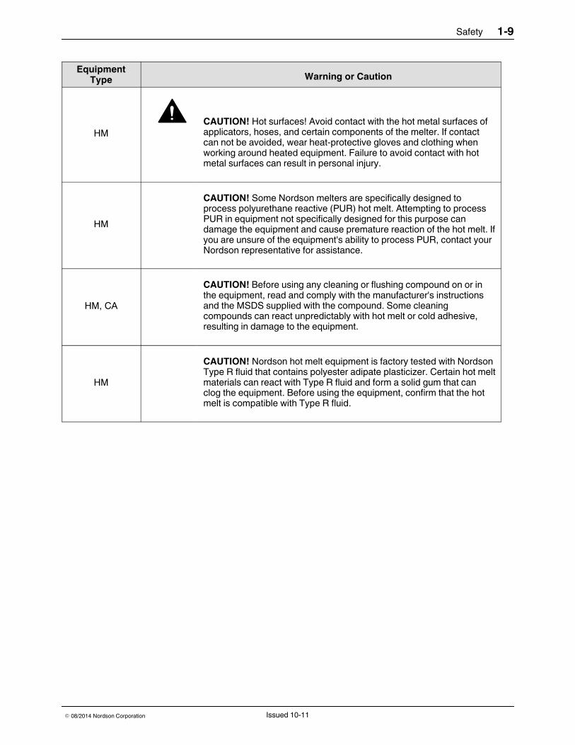
HMCAUTION! Hot surfaces! Avoid contact with the hot metal surfaces ofapplicators, hoses, and certain components of the melter. If contactcan not be avoided, wear heat-protective gloves and clothing whenworking around heated equipment. Failure to avoid contact with hotmetal surfaces can result in personal injury.
HM
CAUTION! Some Nordson melters are specifically designed toprocess polyurethane reactive (PUR) hot melt. Attempting to processPUR in equipment not specifically designed for this purpose candamage the equipment and cause premature reaction of the hot melt. Ifyou are unsure of the equipment's ability to process PUR, contact yourNordson representative for assistance.
HM, CA
CAUTION! Before using any cleaning or flushing compound on or inthe equipment, read and comply with the manufacturer's instructionsand the MSDS supplied with the compound. Some cleaningcompounds can react unpredictably with hot melt or cold adhesive,resulting in damage to the equipment.
HM
CAUTION! Nordson hot melt equipment is factory tested with NordsonType R fluid that contains polyester adipate plasticizer. Certain hot meltmaterials can react with Type R fluid and form a solid gum that canclog the equipment. Before using the equipment, confirm that the hotmelt is compatible with Type R fluid.
Safety1-10
E 08/2014 Nordson CorporationIssued 10- 11
Other Safety PrecautionsS Do not use an open flame to heat hot melt system components.S Check high pressure hoses daily for signs of excessive wear, damage, or
leaks.S Never point a dispensing handgun at yourself or others.S Suspend dispensing handguns by their proper suspension point.
First AidIf molten hot melt comes in contact with your skin:1.. Do NOT attempt to remove the molten hot melt from your skin.2.. Immediately soak the affected area in clean, cold water until the hot melt
has cooled.3.. Do NOT attempt to remove the solidified hot melt from your skin.4.. In case of severe burns, treat for shock.5.. Seek expert medical attention immediately. Give the MSDS for the hot
melt to the medical personnel providing treatment.

Safety 1-11
E 08/2014 Nordson Corporation Issued 10-11
Safety Label and TagFigure 1-1 illustrates the location of the product safety labels and tags affixedto the equipment. Table 1-2 provides an illustration of the hazardidentification symbols that appear on each safety label and tag, the meaningof the symbol, or the exact wording of any safety message.
Figure 1-1 Safety label and tag
Table 1-2Safety Label and TagItem Description1.
WARNING! Risk of electrical shock. Failure to observe may result inpersonal injury, death, or equipment damage.

Safety1-12
E 08/2014 Nordson CorporationIssued 10- 11

Overview 2-1
Part 1123406_01E 08/2014 Nordson Corporation
Section 2Overview
Getting to Know Spectra 30The Spectra 30 pattern controller has the flexibility of having threeconfigurations:S Time-based
The time based functionality enables the pattern controller to monitorconstant line speeds and has an accuracy of +/- 1 ms (1 mm at 60 m/minor 0.1 in. at 500 ft/min).
S Distance (requires encoder)The distance-based functionality enables continuous tracking of lineposition to within one millimeter (or 0.1 inch). This allows dispensing ofprecise adhesive patterns at production speeds that reach300 m/min (983 ft/min). Distance-based systems can also operate intime-base.
S Distance based functionality with inputs/outputs, including one outputwhich is proportional to the line speed (pressure run-up).
NOTE: The needed hardware exists in all the configurations. The functionsare enabled by software licenses.
Overview2-2
Part 1123406_01 E 08/2014 Nordson Corporation
Spectra 30 Pattern Controller and Components
34
1
2
5
6
7
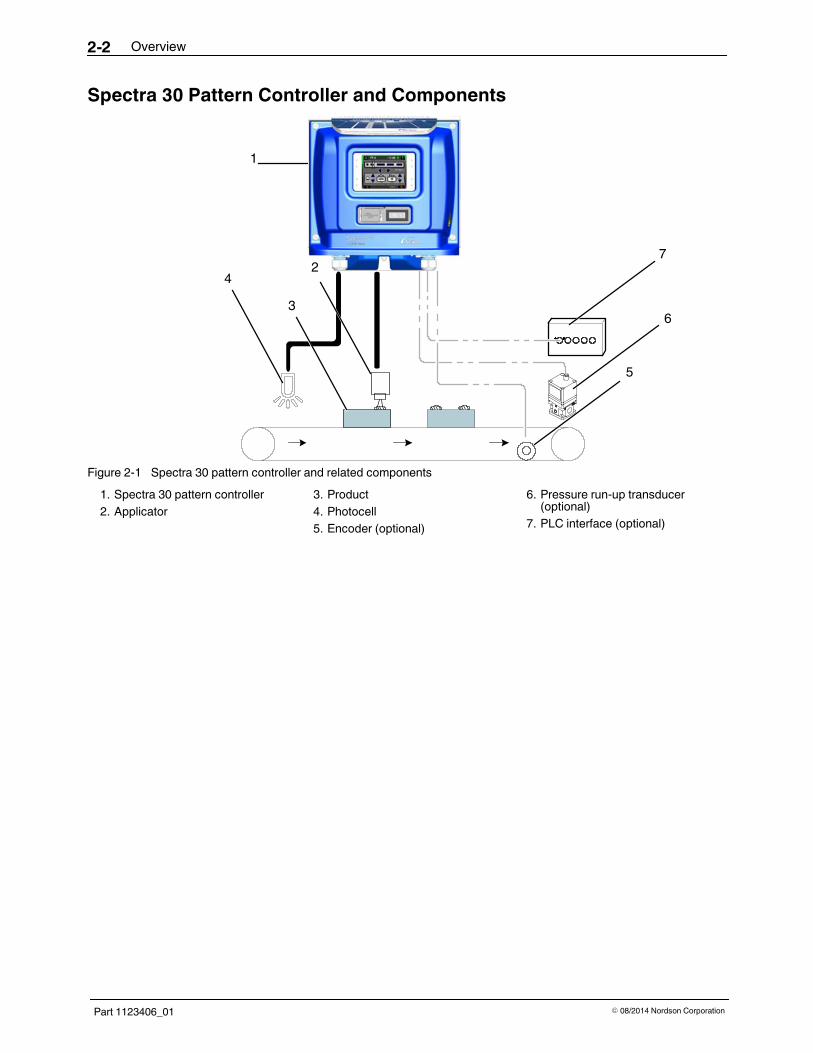
Figure 2-1 Spectra 30 pattern controller and related components1. Spectra 30 pattern controller2. Applicator
3. Product4. Photocell5. Encoder (optional)
6. Pressure run-up transducer(optional)
7. PLC interface (optional)
Overview 2-3
Part 1123406_01E 08/2014 Nordson Corporation
Standard ComponentsSee Figure 2-1 for the components that make up an integrated patterncontrol system. The standard components include:S Spectra 30 pattern controllerS Up to four triggersS Up to four applicators
Add-on FeaturesThe time based and distance and time-based configurations can beupgraded through add-on software licenses, which provide the completeability of the higher option(s). The software licenses can be ordered byspecific part numbers. Refer to Parts for the software license part numbers.
- Encoder- Pressure/Run-up- Remote recall

Overview2-4
Part 1123406_01 E 08/2014 Nordson Corporation
Comparison TableThe following table compares a pattern controller with or without the add-onoptions.
Add-on Options WITH Add-on Features(Software Licences Obtained)
WITHOUT Add-on Features(Software Licences NOT Obtained)
Encoder Time, quadrature and single encodertypes are available.
Time is the only source available.
Power to the encoder is enabled. Power to the encoder is not enabled.Current and encoder pulses aredetected.
Encoder is not detected.
Line speed is computed and scaledbased on the encoder type and scalevalue.
Line speed is constant.(Unscaled, the line speed is 1 ms [1 mmat 60 m/min]).
Encoder screen available. Encoder screen is not available.Enable auto type and direction detectionduring commissioning.
No auto type and direction detection.
Encoder icon is displayed and can betouched.
Encoder icon is not visible.
Encoder related alerts and faultsenabled.
No encoder related alerts and faults.
Pressure/Run-up Run-up output changes based on thecurve defined by the settings.
Run-up does not change.
Output is powered 0 - 10V and4 - 20 mA.
Output set to 0 V.
Run-up icon is displayed and can betouched.
Run-up icon is not visible.
Run-up related alerts and faults enabled. No run-up related alerts and faults.Remote Recall Remote Recall check box is displayed
and can be touched.Remote Recall check box is grayed outand disabled.
Remote recipes are re-callable. No action for changes to inputs.Alerts enabled when a recipe is loaded. No remote recipe alerts or faults.

Overview 2-5
Part 1123406_01E 08/2014 Nordson Corporation
Front PanelThe front panel components are as follows:
1
2
3
Figure 2-2 Front panel components
See Figure 2-2 for the location of the following components.
Front Panel Component Functionality1. LCD Touch screen The graphical 3.5 in. integrated LCD
touch screen is the interface for settingup and monitoring the pattern controller.
2. Switch On/Off switch3. USB Port This port is used for plugging an USB
storage device for:S Upgrading the softwareS Saving a backup of all system
settings and stored recipesS Restoring settingsS Capturing screen shots

Overview2-6
Part 1123406_01 E 08/2014 Nordson Corporation
Base PanelAll the cables are routed through the conduits located on the base panel ofthe pattern controller.
2
1
3 4
5
6
7Figure 2-3 Base panel components
See Figure 2-3 for the location of the following component.
Base Panel Component Functionality1. System Input/Output
(6 in, 2 out)Connects to a PLC type machine.
Output SettingsS AlertS ReadyInput SettingsS Remote recipeS Recall (5, optional)S Unit enable
Continued...

Overview 2-7
Part 1123406_01E 08/2014 Nordson Corporation
See Figure 2-3 for the location of the following components.
Base Panel Component Functionality2. Trigger (1 – 4) S Connects up to four (4) assignable
triggers.S Assigns trigger to any applicator.S Assigns a single trigger to multiple
applicators.S Trigger masking prevents false
triggers.S Measures and displays product
length on-screen in real-time.S PNP/NPN type trigger inputs are
compatible with all legacy andindustry standard photo-eyes.
3. Encoder S Supports one encoderS The following types of encoders can
be used:S quadrature encoders (RS422)S single phase encoders (NPN)
4. Run-up Output and/orFault Machine Stop
Connects to a 0-10 V and 4-20 mApressure transducer.AndConnects to a PLC input or machinestop circuit (N.O and N.C. contacts).
5. Applicator Outputs (1 – 4) S Supports four pattern channeloutputs
S Outputs are 24 VDC, 1Ampmaximum per channel
S Multiple solenoid coils can be usedon one channel up to current limit
S Using an optional external powersupply the system can support up to2Amp maximum per applicator, upto a total of 6 Amps.
6. AC Input Input voltage:120/240 VAC7. Fan location This is optional. A cooling fan can be
installed in this location.

Overview2-8
Part 1123406_01 E 08/2014 Nordson Corporation
Other Sources of InformationRefer to the following resources for getting the most out of your systemcomponents.
Quick Reference GuideThe Quick Reference Guide is affixed to the top panel of the patterncontroller. It provides common setup and pattern generation tasks.
Installation GuideThe Installation Guide provides basic installation, connection, and initialsystem setup instructions.
Product ManualVisit http://emanuals.nordson.com/adhesives to download the productmanuals.
Software Update / Online SupportVisit www.enordson.com/support to view the training videos and to downloadupdates and software utilities.
Advanced Setting UtilityVisit www.enordson.com/support to download the Advanced Setting Utility.This is a PC utility that can be used to make changes to internal settings ofthe pattern controller, that cannot be made through the user interface.

Installation 3-1
Part 1123406_01E 08/2014 Nordson Corporation
Section 3Installation
WARNING! Allow only qualified personnel to perform the following tasks.Follow the safety instructions in this document and all other relateddocumentation.
Mount the Spectra 30Equipment and production line configuration may dictate a variation in themounting options described in this section. Regardless of the mountingmethod used, refer to Guidelines.
Unpacking1. Carefully unpack the pattern controller. Exercise care to prevent
equipment damage during unpacking.2. Inspect for any damage that may have occurred during shipping. Report
any damage to your Nordson representative.
GuidelinesS Position the pattern controller as close as possible to the parent machine
or production line.S Mount the pattern controller vertically on the wall or post.S Ensure that the mounting location provides sufficient clearance around
the bottom of the pattern controller to allow room for cable entry.

Installation3-2
Part 1123406_01 E 08/2014 Nordson Corporation
DimensionsUse the following dimensions to mount the pattern controller.
9.76 in.(248 mm)
9.84in.
(250m
m)
5.66 in.(144 mm)Right Panel
Front Panel
3.93 in.(100 mm)
2.95 in.(75 mm)
3.93in.
(100
mm)
2.95in.
(75m
m)
Back Panel*
Figure 3-1 Pattern Controller dimensions
*NOTE: The back mounting plate has a standard VESA mounting pattern,which allows the use of off-the-shelf mounting accessories.

Installation 3-3
Part 1123406_01E 08/2014 Nordson Corporation
Mounting the Pattern Controller1. Locate the following components required for mounting the pattern
controller.
1
2
3
Figure 3-2 Mounting components1. Back panel2. Mounting slot
3. Mounting plate
2. Loosen the socket head mounting screw from the pattern controller toremove the mounting plate. Retain the mounting screw for re-installingthe mounting plate to the pattern controller.
1
Figure 3-3 Mounting the pattern controller1. One Socket head screw

x
Installation3-4
Part 1123406_01 E 08/2014 Nordson Corporation
Mounting the Pattern Controller (contd)3. Slide the mounting plate out from the mounting slot. See Figure 3-4.4. Mount the mounting plate on a rigid support (e.g. wall or post) to prevent
external vibration.5. Secure the mounting plate by installing the screws provided in the
ship-with kit. Refer to Parts section for the ship-with kit part number.6. Position the pattern controller and slide it into the installed mounting
plate.7. Using the socket head mounting screw removed in step 2 secure the
pattern controller to the mounting plate.
Figure 3-4Removing themounting plate

Installation 3-5
Part 1123406_01E 08/2014 Nordson Corporation
Connect the Spectra 30WARNING! Equipment must be properly grounded and fused according toits rated current consumption (see ID plate). Failure to follow the safetyprocedures can result in serious injury.
1. Remove the pattern controller cover by loosening the four M5 captivescrews to access the internal boards.
Figure 3-5 Pattern controller cover removal2. Route all the cables through the conduits located on the base panel of
the pattern controller, see Figure 3-6.Refer to theWiring Diagram for connecting the device specific cables tothe proper location on the corresponding boards.
Figure 3-6 Routing the cables

Installation3-6
Part 1123406_01 E 08/2014 Nordson Corporation
This page intentionally left blank.

Installation 3-7
Part 1123406_01E 08/2014 Nordson Corporation
Internal Wiring
Allow only personnel with appropriate training andexperience to operate or service the equipment. Theuse of untrained or inexperienced personnel tooperate or service the equipment can result in injury,including death, to themselves and others, anddamage to the equipment.
Warning: Warning:Equipment must be properly grounded and fused according to its rated current consumption (see ID plate).Failure to follow the safety procedures can result in serious injury.
JP2
JP3/4
JP4
JP17
JP5
JP16
Install cooling fan if needed(optional)*Install PG connectors fromship-with kit as needed
AC Input
PE (Ground)
Conduit
Trigger (1-4)Encoder (1)
Run-up Out (1)/Machine Stop
OutputsApplicator Outputs
(4)
SystemInput/Output(4 In, 2 Out)*
ConnectingLocation
L2L1 L2/N
PE/G
Ref
Refer to Important Wiring Details andWire Gauge Range given next.Figure 3-7 Internal board and cable connection details
Installation3-8
E 08/2014 Nordson CorporationPart 1123406_01
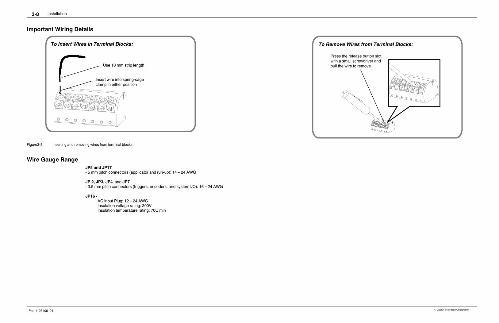
Important Wiring Details
To Insert Wires in Terminal Blocks:
Use 10 mm strip length
To Remove Wires from Terminal Blocks:
Insert wire into spring-cageclamp in either position
Press the release button slotwith a small screwdriver andpull the wire to remove
Figure3-8 Inserting and removing wires from terminal blocks
Wire Gauge RangeJP5 and JP17- 5 mm pitch connectors (applicator and run-up): 14 – 24 AWG
JP 2, JP3, JP4 and JP7- 3.5 mm pitch connectors (triggers, encoders, and system I/O): 16 – 24 AWG
JP16 -AC Input Plug: 12 – 24 AWGInsulation voltage rating: 300VInsulation temperature rating: 70C min

Installation 3-9
Part 1123406_01E 08/2014 Nordson Corporation
Before Setting Up Spectra 30WARNING! Allow only qualified personnel to perform the following tasks.Follow the safety instructions in this document and all other relateddocumentation.
Before setting up the pattern controller make sure of the following:1. Pattern controller cover removed in step 1 under Connect Spectra 30
given earlier is re-installed.2. Pattern controller components are connected.3. Pattern controller power cable is connected to a grounded outlet.4. Pattern controller switch is turned on.
Figure 3-9 Main Switch location

Installation3-10
Part 1123406_01 E 08/2014 Nordson Corporation
The User Interface 4-1
Part 1123406_01E 08/2014 Nordson Corporation
Section 4The User Interface
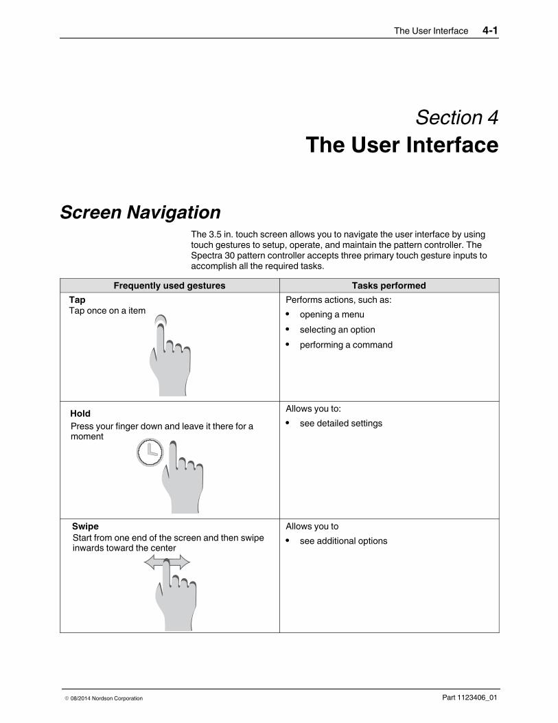
Screen NavigationThe 3.5 in. touch screen allows you to navigate the user interface by usingtouch gestures to setup, operate, and maintain the pattern controller. TheSpectra 30 pattern controller accepts three primary touch gesture inputs toaccomplish all the required tasks.
Frequently used gestures Tasks performedTapTap once on a item
Performs actions, such as:S opening a menuS selecting an optionS performing a command
HoldPress your finger down and leave it there for amoment
Allows you to:S see detailed settings
SwipeStart from one end of the screen and then swipeinwards toward the center
Allows you toS see additional options
The User Interface4-2
Part 1123406_01 E 08/2014 Nordson Corporation
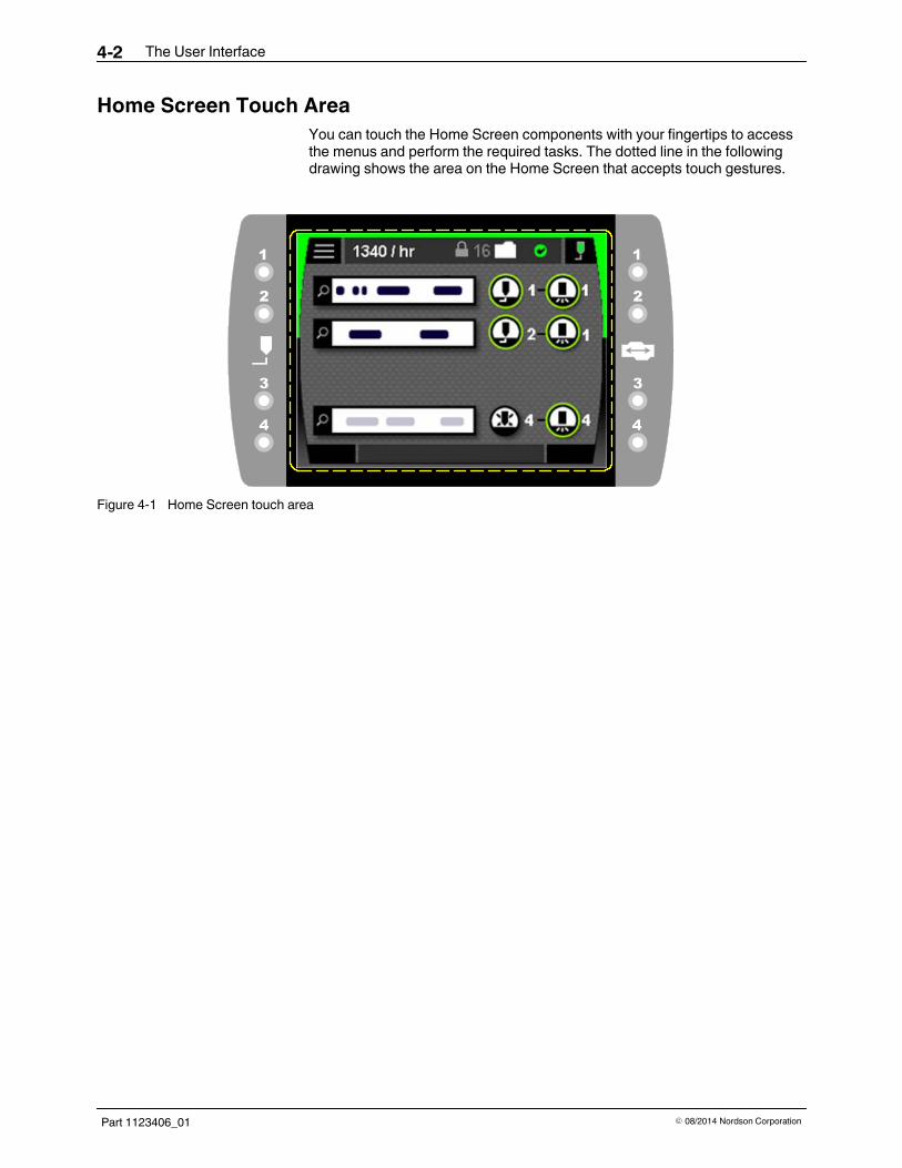
Home Screen Touch AreaYou can touch the Home Screen components with your fingertips to accessthe menus and perform the required tasks. The dotted line in the followingdrawing shows the area on the Home Screen that accepts touch gestures.
Figure 4-1 Home Screen touch area
The User Interface 4-3
Part 1123406_01E 08/2014 Nordson Corporation
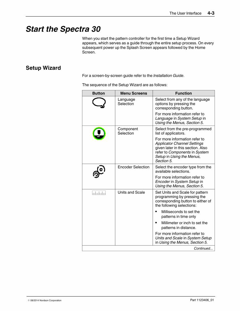
Start the Spectra 30When you start the pattern controller for the first time a Setup Wizardappears, which serves as a guide through the entire setup process. On everysubsequent power up the Splash Screen appears followed by the HomeScreen.
Setup WizardFor a screen-by-screen guide refer to the Installation Guide.
The sequence of the Setup Wizard are as follows:Button Menu Screens Function
LanguageSelection
Select from any of the languageoptions by pressing thecorresponding button.For more information refer toLanguage in System Setup inUsing the Menus, Section 5.
ComponentSelection
Select from the pre-programmedlist of applicators.For more information refer toApplicator Channel Settingsgiven later in this section. Alsorefer to Components in SystemSetup in Using the Menus,Section 5.
Encoder Selection Select the encoder type from theavailable selections.For more information refer toEncoder in System Setup inUsing the Menus, Section 5.
Units and Scale Set Units and Scale for patternprogramming by pressing thecorresponding button to either ofthe following selections:S Milliseconds to set the
patterns in time onlyS Millimeter or inch to set the
patterns in distance.For more information refer toUnits and Scale in System Setupin Using the Menus, Section 5.
Continued...

The User Interface4-4
Part 1123406_01 E 08/2014 Nordson Corporation
Setup Wizard (contd)
Button Menu Screens FunctionInput Set up system inputs for:
S Remote recipe selectionS Remote system enable
NOTE: Set remote enable toactive high (24 VDC) oractive low (0 VDC).
For more information refer toInput in System Setup in Usingthe Menus, Section 5.
Output Set up system outputs for:S Active high (24 VDC)S Active low (0 VDC).NOTE: The fault/machine stopsetting is typically set for activelow to provide fail safe operation(power off or loose wire conditionis faulted).For more information refer toOutput in System Setup in Usingthe Menus, Section 5.
Machine Settings Select from the following options:S Individual or multiple recipe
filesS Select adhesive output On or
Off when power is turned onS Line speed value when
adhesive output starts andstops (encoder only)
For more information refer toMachine Settings in SystemSetup in Using the Menus,Section 5.
Continued...

The User Interface 4-5
Part 1123406_01E 08/2014 Nordson Corporation
FunctionMenu ScreensButton
+ AdditionalMachine Settings
Select from the following options:S Set trigger timeout:S in seconds when in time
modeS in distance when encoder
is used
S Select product skip (orpalletizing)
S Trigger memoryS enable product queuing
after line stopS disable product queuing
after line stopFor more information refer toTrigger Settings given later inthis section. Also refer toAdditional Machine Settings inSystem Setup in Using theMenus, Section 5.
Passwords Select a password using thenumeric keypad to protect thescreens.For more information refer toPassword Lock/Unlock in Usingthe Menus, Section 5
1 2 3
The User Interface4-6
Part 1123406_01 E 08/2014 Nordson Corporation
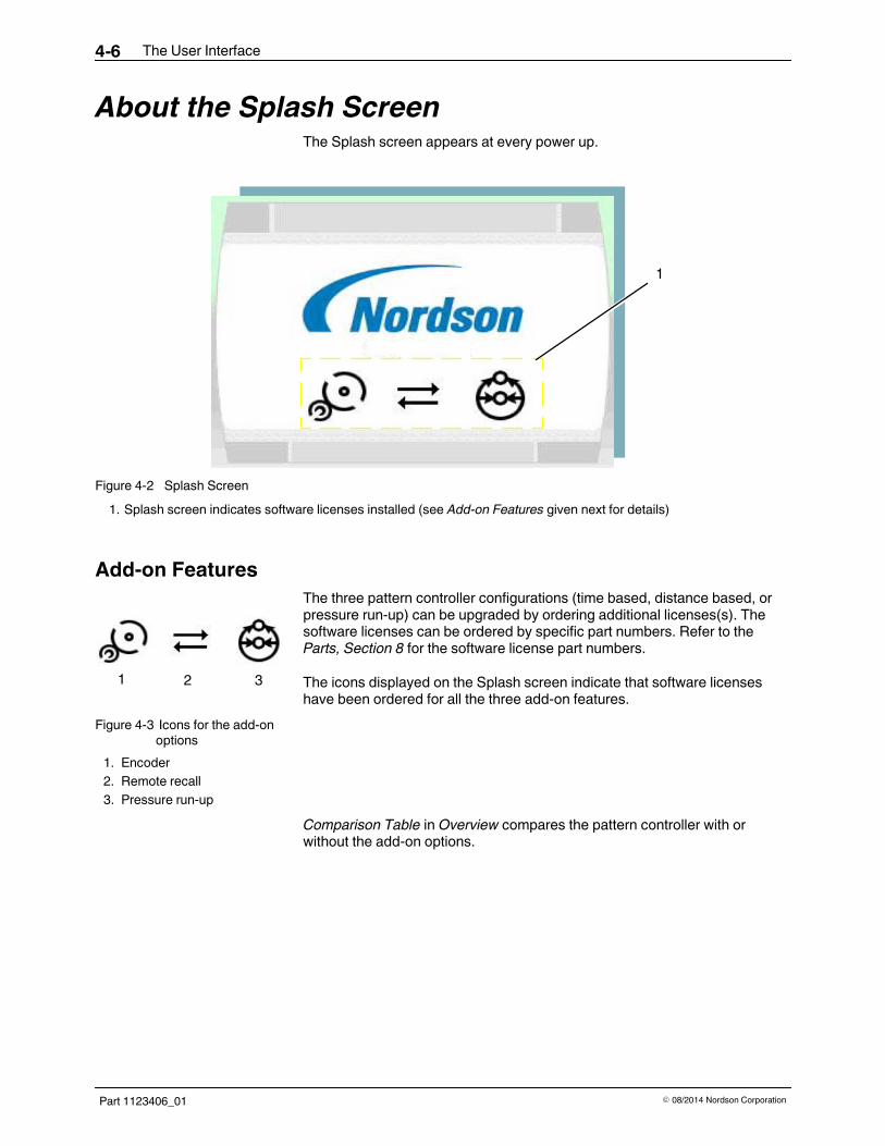
About the Splash ScreenThe Splash screen appears at every power up.
1
Figure 4-2 Splash Screen1. Splash screen indicates software licenses installed (see Add-on Features given next for details)
Add-on FeaturesThe three pattern controller configurations (time based, distance based, orpressure run-up) can be upgraded by ordering additional licenses(s). Thesoftware licenses can be ordered by specific part numbers. Refer to theParts, Section 8 for the software license part numbers.
The icons displayed on the Splash screen indicate that software licenseshave been ordered for all the three add-on features.
Figure 4-3 Icons for the add-onoptions
1. Encoder2. Remote recall3. Pressure run-up
Comparison Table in Overview compares the pattern controller with orwithout the add-on options.
The User Interface 4-7
Part 1123406_01E 08/2014 Nordson Corporation
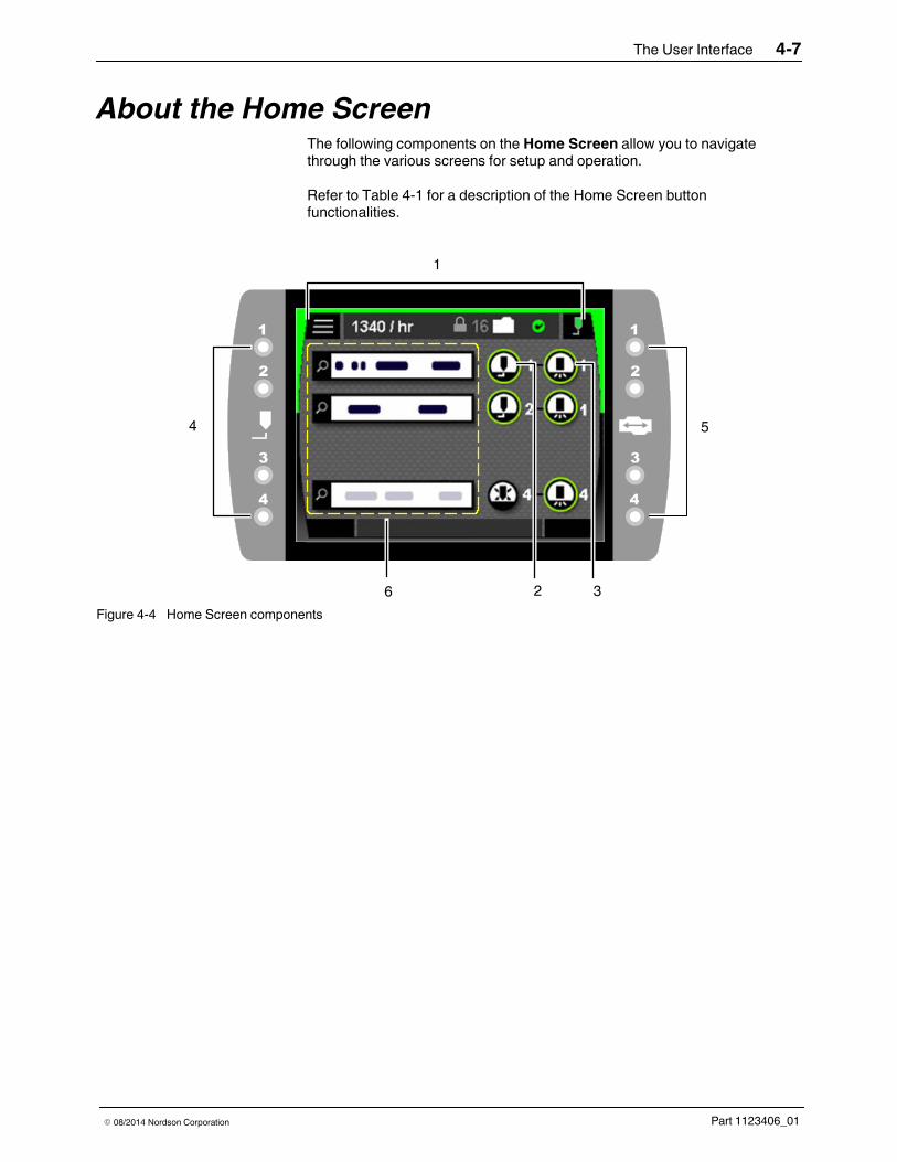
About the Home ScreenThe following components on the Home Screen allow you to navigatethrough the various screens for setup and operation.
Refer to Table 4-1 for a description of the Home Screen buttonfunctionalities.
2 3
4 5
6
1
Figure 4-4 Home Screen components

The User Interface4-8
Part 1123406_01 E 08/2014 Nordson Corporation
About the Home Screen (contd)See Figure 4-4 for the location of Home Screen components.
Table 4-1 Home Screen components
Item Component Functions
1 Status Bar
The status bar contains components to:S Navigate to system menusS Monitor the systemS Select and modify recipesS Turn adhesive dispensing on and off
Item Component Button State Status
2 Applicator
Applicator is enabled
Applicator is disabled
Applicator is in an alert condition
Applicator is in a fault condition
3 Trigger
Trigger is enabled
Trigger is in an alert condition
Trigger is in an fault condition
4 Applicator LEDs Applicator is activated
5 Trigger LEDs Trigger is activated
Item Component Functions
6 Pattern S Displays bead patternsS Allows modification of the bead pattern
The User Interface 4-9
Part 1123406_01E 08/2014 Nordson Corporation
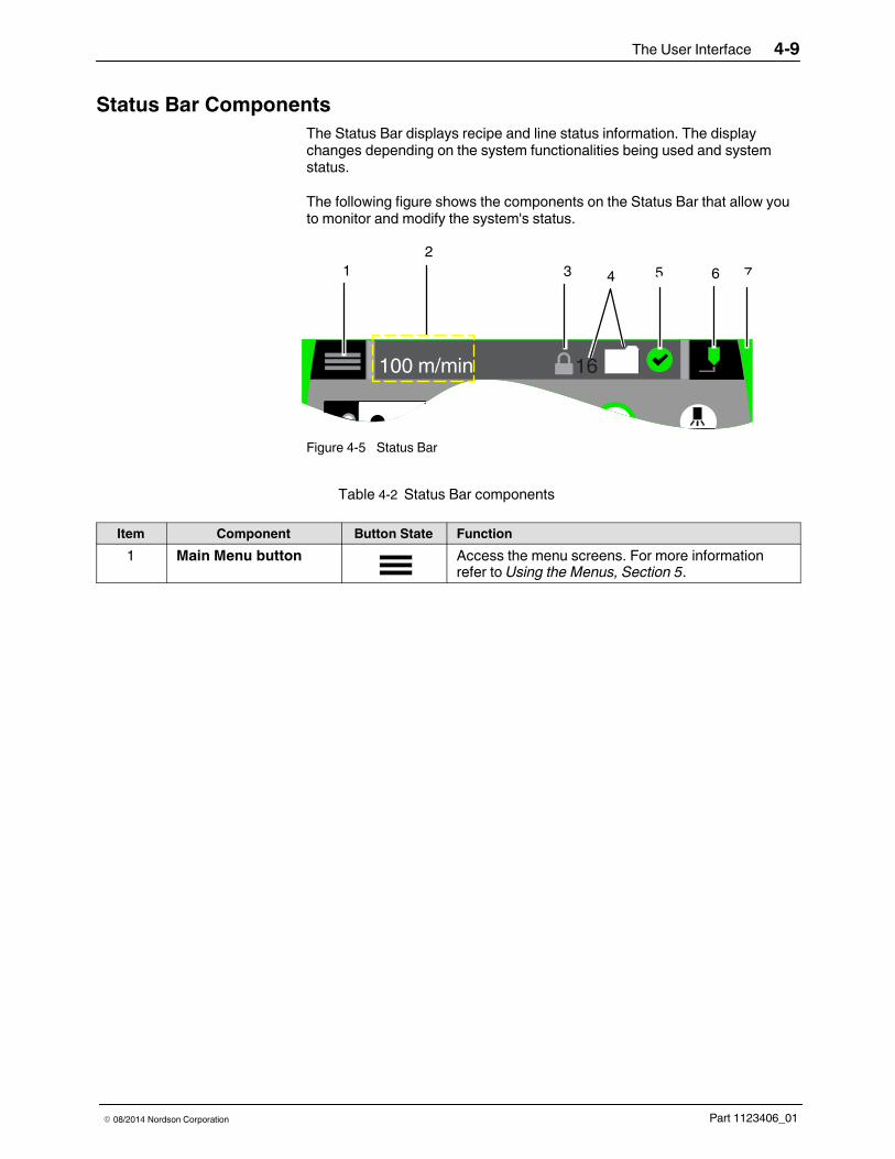
Status Bar ComponentsThe Status Bar displays recipe and line status information. The displaychanges depending on the system functionalities being used and systemstatus.
The following figure shows the components on the Status Bar that allow youto monitor and modify the system's status.
1
100 m/min 16
23 4 5 76
Figure 4-5 Status Bar
Table 4-2 Status Bar components
Item Component Button State Function1 Main Menu button Access the menu screens. For more information
refer to Using the Menus, Section 5.
The User Interface4-10
Part 1123406_01 E 08/2014 Nordson Corporation
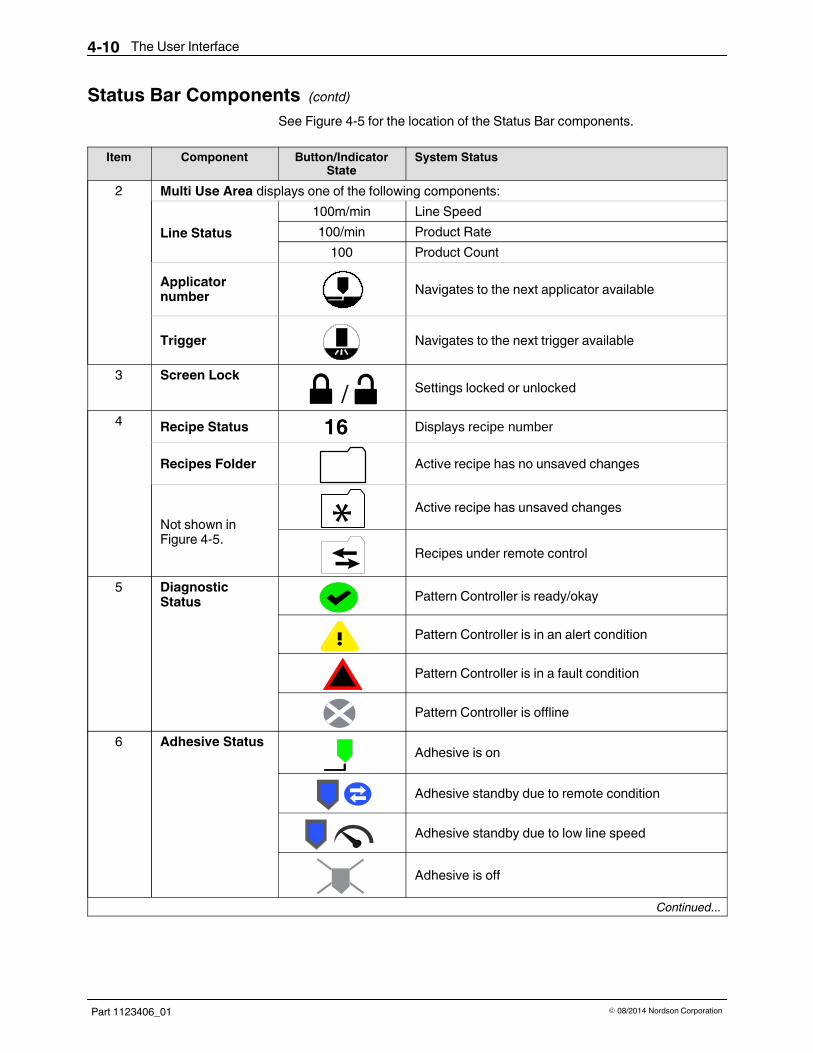
Status Bar Components (contd)See Figure 4-5 for the location of the Status Bar components.
Item Component Button/IndicatorState
System Status
2 Multi Use Area displays one of the following components:
Line Status100m/min Line Speed100/min Product Rate100 Product Count
Applicatornumber Navigates to the next applicator available
Trigger Navigates to the next trigger available
3 Screen Lock/ Settings locked or unlocked
4 Recipe Status 16 Displays recipe number
Recipes Folder Active recipe has no unsaved changes
Not shown inFigure 4-5.
Active recipe has unsaved changes
Recipes under remote control
5 DiagnosticStatus Pattern Controller is ready/okay
Pattern Controller is in an alert condition
Pattern Controller is in a fault condition
Pattern Controller is offline6 Adhesive Status Adhesive is on
Adhesive standby due to remote condition
Adhesive standby due to low line speed
Adhesive is off
Continued...

The User Interface 4-11
Part 1123406_01E 08/2014 Nordson Corporation
See Figure 4-5 for the location of the Status Bar component.
Item Component Button Color Button State System StatusSystem Outputs
Ready Alert Fault7 System
StatusRun Adhesive is being
dispensed On Off Off
Standby System is in standbycondition On Off Off
Alert System is in alertcondition On On Off
Fault System is in faultcondition Off On/
Off On
Offline System is offlineOff Off Off

The User Interface4-12
Part 1123406_01 E 08/2014 Nordson Corporation
Using the Home ScreenThe pattern controller is shipped from the factory with most software settingspre-configured and ready to use. However, there are some settings that youmust configure and fine tune to best fit your manufacturing process.
Use the Home Screen components to view and re-configure the patterncontroller settings.
1
3 52 4
96
7
8Figure 4-6 Home Screen
1. Main Menu button2. Password lock3. Recipe
4. Message log5. Adhesive button6. Trigger button
7. Enabled applicator button8. Disabled applicator button9. Pattern overview
The User Interface 4-13
Part 1123406_01E 08/2014 Nordson Corporation
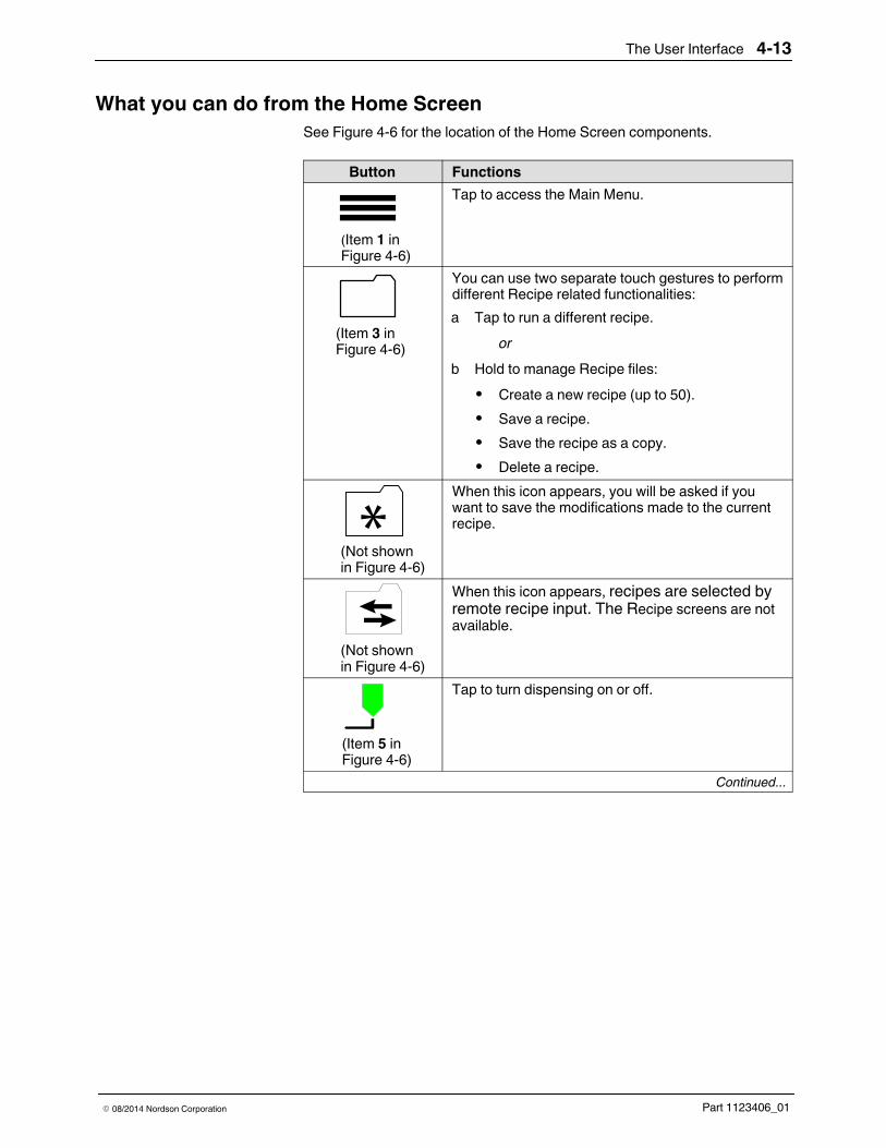
What you can do from the Home ScreenSee Figure 4-6 for the location of the Home Screen components.
Button Functions
(Item 1 inFigure 4-6)
Tap to access the Main Menu.
(Item 3 inFigure 4-6)
You can use two separate touch gestures to performdifferent Recipe related functionalities:a Tap to run a different recipe.
orb Hold to manage Recipe files:S Create a new recipe (up to 50).S Save a recipe.S Save the recipe as a copy.S Delete a recipe.
(Not shownin Figure 4-6)
When this icon appears, you will be asked if youwant to save the modifications made to the currentrecipe.
(Not shownin Figure 4-6)
When this icon appears, recipes are selected byremote recipe input. The Recipe screens are notavailable.
(Item 5 inFigure 4-6)
Tap to turn dispensing on or off.
Continued...

The User Interface4-14
Part 1123406_01 E 08/2014 Nordson Corporation
What you can do from the Home Screen (contd)See Figure 4-6 for the location of the Home Screen components.
Button Functions
(Item 6 inFigure 4-6)
Hold to modify Trigger Settings.a Polarityb Masking distancec Palletize
(Item 7 inFigure 4-6)
You can use two separate touch gestures to set ormodify different Applicator menu functionalities:
a Tap to access the Purge screen.b Hold to view or modify:S Pattern typeS Trigger numberS Gun-to-trigger offsetS Copy/Paste patternsS Enable/Disable applicator
(Item 9 inFigure 4-6)
Tap to view or modify the selected pattern.
(Item 4 inFigure 4-6)
Tap to access the message log.
(Item 2 inFigure 4-6)
Tap to lock or unlock the settings. A password mustbe entered to unlock screens.NOTE: No icon is displayed when Screen Lock isnot enabled.

The User Interface 4-15
Part 1123406_01E 08/2014 Nordson Corporation
Pattern ProgrammingTo access the Pattern Selection screen, do the following:1. Hold the Applicator button on the Home Screen to access the
Applicator Setup screen.
1
2Figure 4-7 Pattern related components
1. Select pattern type button 2. Pattern display

The User Interface4-16
Part 1123406_01 E 08/2014 Nordson Corporation
Pattern Programming (contd)
2. Tap the Select Pattern Type button to access the Pattern TypeSelection screen.
2
4
5
3
1
Figure 4-8 Pattern Type Selection screen1. Normal bead pattern2. EcoBead pattern
3. Dot bead pattern4. Random bead pattern
5. Random mirror bead pattern
3. Select a pattern type from the available selection.

The User Interface 4-17
Part 1123406_01E 08/2014 Nordson Corporation
Normal PatternNormal patterns or solid beads are generated when the line speed is abovethe start speed. This is the default pattern type for the system.
Assign the delay and the length values. Delay is the distance from theleading edge of the product to the beginning of the bead, and length is thedistance from the start of the bead to the end of the bead.
12
4 3
56
8
7
910 11
13
12
14
10
Figure 4-9 Components for setting normal patterns1. Unselected beads2. Bead length3. Selected bead4. Current applicator5. Pattern display
6. Bead offset7. Bead delay increment tool8. Bead delay value9. Units used
10. Panel swipe tool
11. Bead length12. Bead length increment tool13. Product length14. Bead selector

The User Interface4-18
Part 1123406_01 E 08/2014 Nordson Corporation
Normal Pattern (contd)
NOTES:S Pattern display (item 5 in Figure 4-9) updates automatically as pattern are
modified.S Select beads by tapping the beads or using the bead selector arrows
(item 14 in Figure 4-9).S Adjust delay or length values using the incremental tools (items 7 and 12
in Figure 4-9), or tapping the bead delay and bead length numeric entrykeypads (items 8 and 11 in Figure 4-9).
S Select a different applicator channel by tapping the applicator icon(item 4 in Figure 4-9).
S View product length (item 13 in Figure 4-9) as measured by the assignedtrigger input in real-time.
Normal Pattern Swipe OperationThe number of dots on the swipe tool indicates the number of panelsavailable. Two panels are available for pattern edits when Normal pattern isselected.
Access additional pattern setting functionality by swiping left or right on thepanel shown below.
3
2
1
Figure 4-10 Normal pattern swipe and pattern edit panels1. Insert selected bead before 2. Delete selected bead 3. Insert selected bead after
The User Interface 4-19
Part 1123406_01E 08/2014 Nordson Corporation
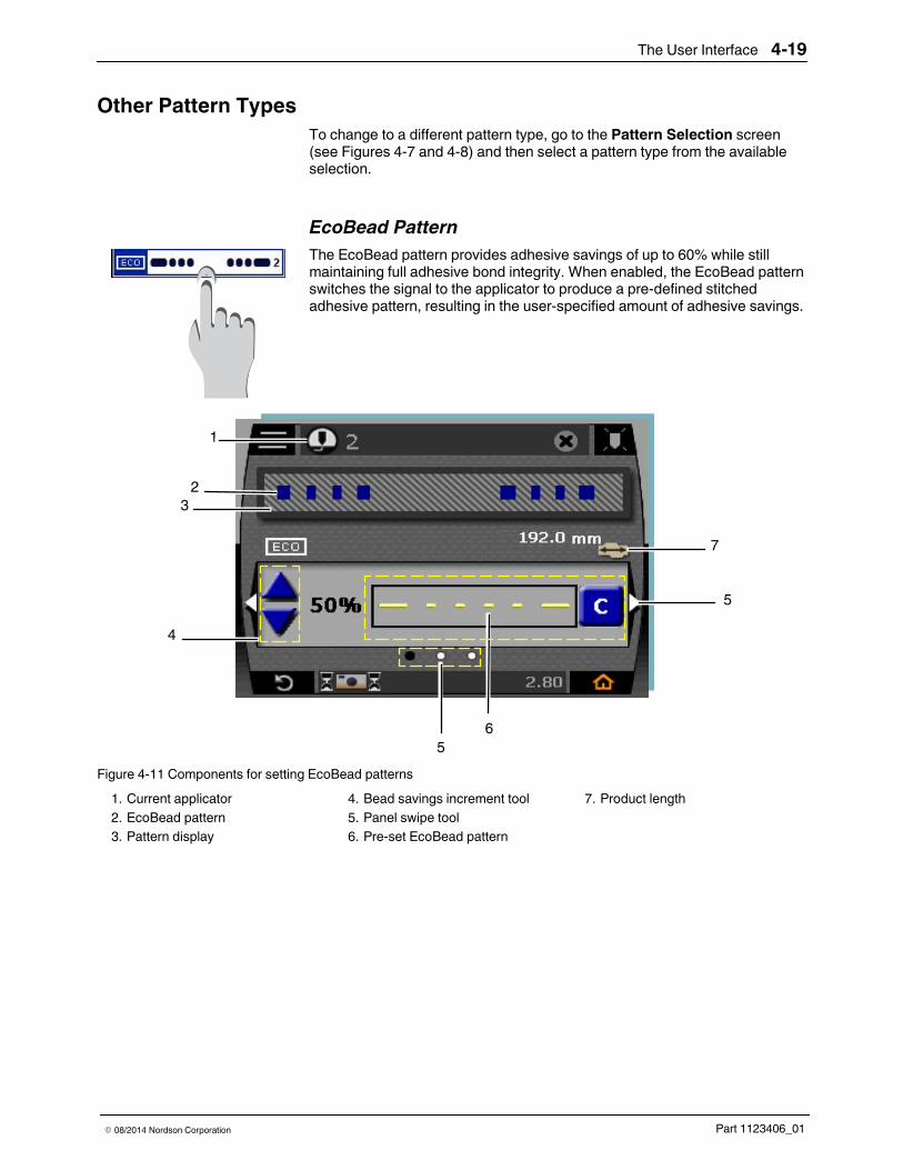
Other Pattern TypesTo change to a different pattern type, go to the Pattern Selection screen(see Figures 4-7 and 4-8) and then select a pattern type from the availableselection.
EcoBead PatternThe EcoBead pattern provides adhesive savings of up to 60% while stillmaintaining full adhesive bond integrity. When enabled, the EcoBead patternswitches the signal to the applicator to produce a pre-defined stitchedadhesive pattern, resulting in the user-specified amount of adhesive savings.
1
2
4
3
56
7
5
Figure 4-11 Components for setting EcoBead patterns1. Current applicator2. EcoBead pattern3. Pattern display
4. Bead savings increment tool5. Panel swipe tool6. Pre-set EcoBead pattern
7. Product length
The User Interface4-20
Part 1123406_01 E 08/2014 Nordson Corporation
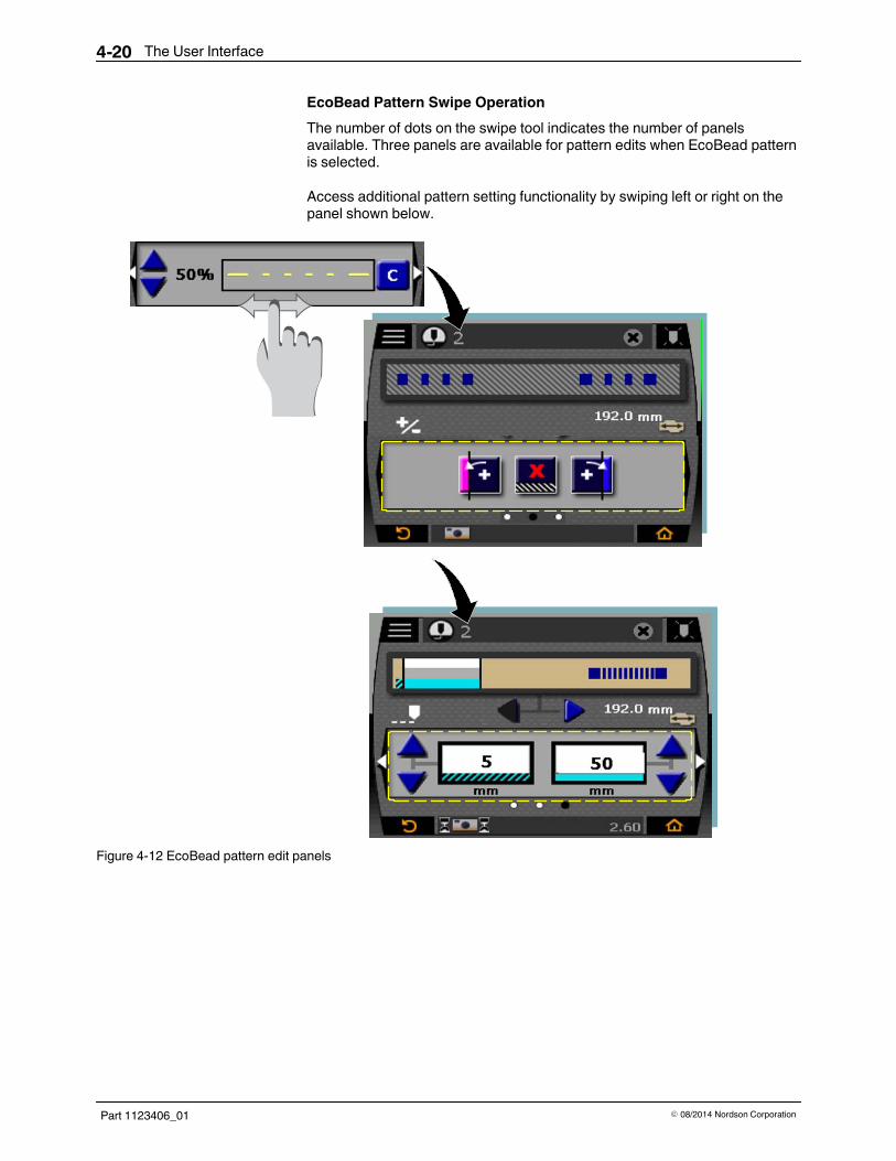
EcoBead Pattern Swipe OperationThe number of dots on the swipe tool indicates the number of panelsavailable. Three panels are available for pattern edits when EcoBead patternis selected.
Access additional pattern setting functionality by swiping left or right on thepanel shown below.
80
Figure 4-12 EcoBead pattern edit panels
The User Interface 4-21
Part 1123406_01E 08/2014 Nordson Corporation
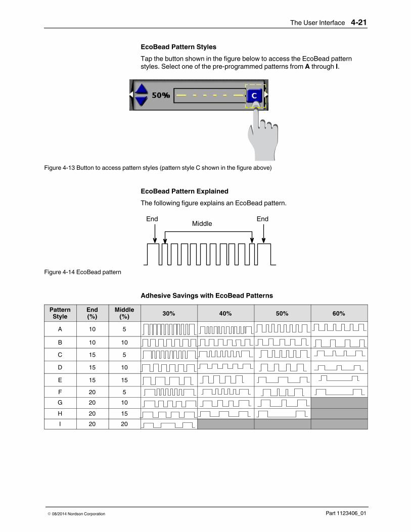
EcoBead Pattern StylesTap the button shown in the figure below to access the EcoBead patternstyles. Select one of the pre-programmed patterns from A through I.
Figure 4-13 Button to access pattern styles (pattern style C shown in the figure above)
EcoBead Pattern ExplainedThe following figure explains an EcoBead pattern.
MiddleEnd End
Figure 4-14 EcoBead pattern
Adhesive Savings with EcoBead PatternsPatternStyle
End(%)
Middle(%) 30% 40% 50% 60%
A 10 5B 10 10C 15 5D 15 10E 15 15F 20 5G 20 10H 20 15I 20 20

The User Interface4-22
Part 1123406_01 E 08/2014 Nordson Corporation
Dot PatternThis pattern type provides patterns of constant weight (volume) of adhesivedots that are spaced by a user-determined distance.
1
2
4
3
5 6 87
9
10
7
Figure 4-15 Components for setting dot patterns1. Current applicator2. Dot pattern3. Pattern display
4. Dot time increment tool5. Dot time value6. Units used
7. Panel swipe tool8. Dot pitch value9. Dot pitch increment tool
10. Product length
Dot Pattern Example
Time
10 ms
5 ms
2 ms
Pitch = 25 mm (1.0 in.)
178 mm (7.0 in.)Dur 1
Figure 4-16 Example Dot Pattern Types (Effect on dot size of decreasing gun-on timefrom 10 ms [top] to 2 ms [bottom]

The User Interface 4-23
Part 1123406_01E 08/2014 Nordson Corporation
Dot Pattern Swipe OperationThe number of dots on the swipe tool indicates the number of panelsavailable. Three panels are available for pattern edits when Dot pattern isselected.
Access additional pattern setting functionality by swiping left or right on thepanel shown below.
Figure 4-17 Dot pattern edit panels

The User Interface4-24
Part 1123406_01 E 08/2014 Nordson Corporation
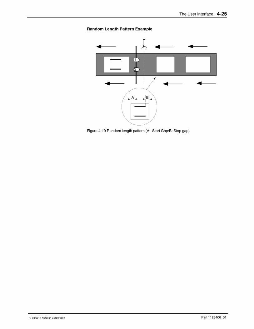
Random Length PatternThis pattern type provides a way to mix products of differing length on theproduction line during the same production run. When alternating betweenshort and long products on the production line, the system is programmed toautomatically determine the length of each product as it passes the trigger,and it then adjusts the bead size to fit the product.
1
2
4
3
5 6
8
7
9
10
Figure 4-18 Components for setting random bead patterns1. Current applicator channel2. Pattern display3. Leading edge margin4. Leading edge margin increment
tool
5. Leading edge margin value6. Trailing edge margin value7. Trailing edge margin value
increment tool
8. Product length9. Trailing edge margin
10. Bead
The User Interface 4-25
Part 1123406_01E 08/2014 Nordson Corporation
Random Length Pattern Example
1
2
A B
Figure 4-19 Random length pattern (A: Start Gap/B: Stop gap)

The User Interface4-26
Part 1123406_01 E 08/2014 Nordson Corporation
Random Mirror Mode PatternThis bead type places the pattern on the leading edge and a mirror image onthe trailing edge.
12
4
3
56
8
7
9 1011
13
1210
14
Figure 4-20 Components for setting random mirror mode patterns1. Unselected bead2. Bead length3. Selected bead4. Current applicator5. Pattern display
6. Bead delay7. Bead delay increment tool8. Bead offset margin value9. Units
10. Swipe tool
11. Bead duration value12. Bead length increment tool13. Product length14. Bead selector
Random Mirror Mode Pattern Example
GTO
RANDOM
Offset - X
Offset - 1
Direction of Production Line
LENGTH
(up to 4 beads)
Length-1 Length-X Length-1Length-X
Offset
Figure 4-21 Example of Random Mirror Mode Pattern Types
The User Interface 4-27
Part 1123406_01E 08/2014 Nordson Corporation
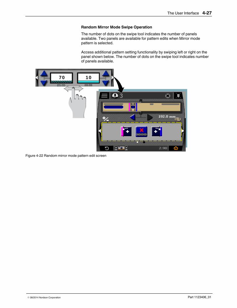
Random Mirror Mode Swipe OperationThe number of dots on the swipe tool indicates the number of panelsavailable. Two panels are available for pattern edits when Mirror modepattern is selected.
Access additional pattern setting functionality by swiping left or right on thepanel shown below. The number of dots on the swipe tool indicates numberof panels available.
70 10mm
Figure 4-22 Random mirror mode pattern edit screen

The User Interface4-28
Part 1123406_01 E 08/2014 Nordson Corporation
Applicator Channel SettingsHold the Applicator button on the Home Screen to access the ApplicatorSetup screen.
1
2
3
46
7
5
8
100
Figure 4-23 Applicator screen components1. Select pattern type2. Select trigger3. Paste pattern
4. Copy pattern5. Gun-to-trigger offset (GTO)6. Pattern overview
7. Applicator Enable/Disable8. Current applicator
The User Interface 4-29
Part 1123406_01E 08/2014 Nordson Corporation
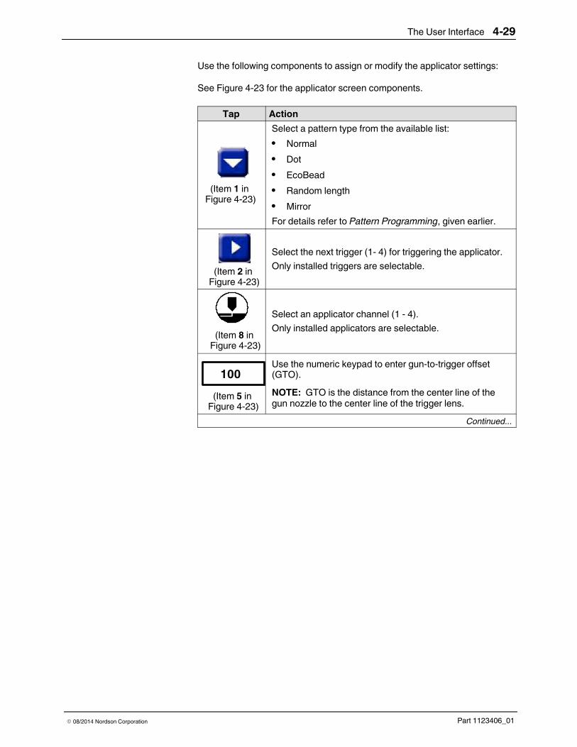
Use the following components to assign or modify the applicator settings:
See Figure 4-23 for the applicator screen components.
Tap Action
(Item 1 inFigure 4-23)
Select a pattern type from the available list:S NormalS DotS EcoBeadS Random lengthS MirrorFor details refer to Pattern Programming, given earlier.
(Item 2 inFigure 4-23)
Select the next trigger (1- 4) for triggering the applicator.Only installed triggers are selectable.
(Item 8 inFigure 4-23)
Select an applicator channel (1 - 4).Only installed applicators are selectable.
(Item 5 inFigure 4-23)
100Use the numeric keypad to enter gun-to-trigger offset(GTO).NOTE: GTO is the distance from the center line of thegun nozzle to the center line of the trigger lens.
Continued...

The User Interface4-30
Part 1123406_01 E 08/2014 Nordson Corporation
Applicator Channel Settings (contd)See Figure 4-23 for the applicator screen components.
Tap Action
(Item 7 inFigure 4-23)
Enable the applicator for dispensing adhesive.
(Item 4 inFigure 4-23)
Copy the settings into the pattern clipboard.
(Item 3 inFigure 4-23)
Paste the settings from the the pattern clipboard.NOTE: This button can be enabled only when there is apattern in the clipboard.
(Item 6 inFigure 4-23)
View/modify the pattern.
The User Interface 4-31
Part 1123406_01E 08/2014 Nordson Corporation
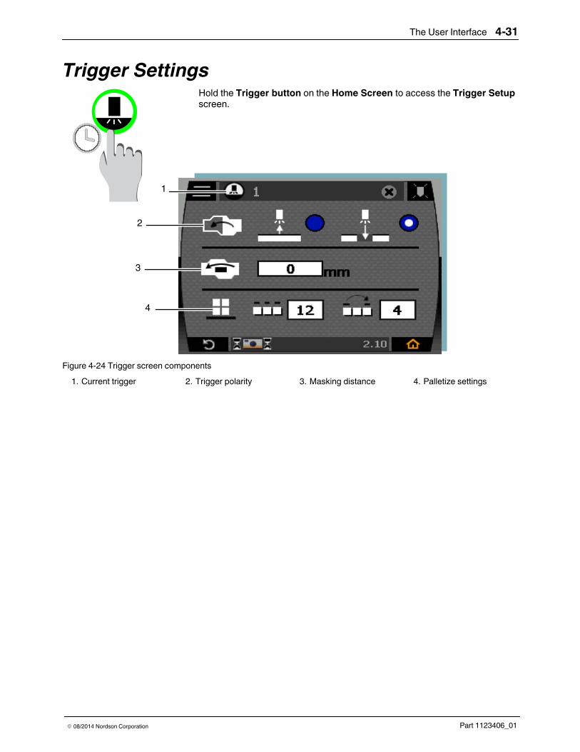
Trigger SettingsHold the Trigger button on the Home Screen to access the Trigger Setupscreen.
3
4
2
1
Figure 4-24 Trigger screen components1. Current trigger 2. Trigger polarity 3. Masking distance 4. Palletize settings

The User Interface4-32
Part 1123406_01 E 08/2014 Nordson Corporation
Trigger Settings (contd)Use the following components to assign or modify the trigger settings:
See Figure 4-24 for the trigger screen components.
Tap Action
(Item 1 inFigure 4-24)
Tap to select the next trigger.
(Item 2 inFigure 4-24)
Select this setting to determine theTrigger Polarity (light on or dark on) ofthe trigger (1 - 4).
(Item 3 inFigure 4-24)
100 SelectMasking Distance when theproducts contain holes or have cutouts.This setting is used to lock the trigger fora predetermined distance.
(Item 4 inFigure 4-24)
Select Palletize Settings forprogramming the number of consecutiveproducts that will receive adhesive andthe number of consecutive products thatwill be skipped before pattern generationstarts.NOTE: Palletize settings will not beavailable if the Product Skip setting isnot selected on the Additional MachineSettings screen. Refer to AdditionalMachine Settings in System Setup inUsing the Menus, Section 5.
The User Interface 4-33
Part 1123406_01E 08/2014 Nordson Corporation
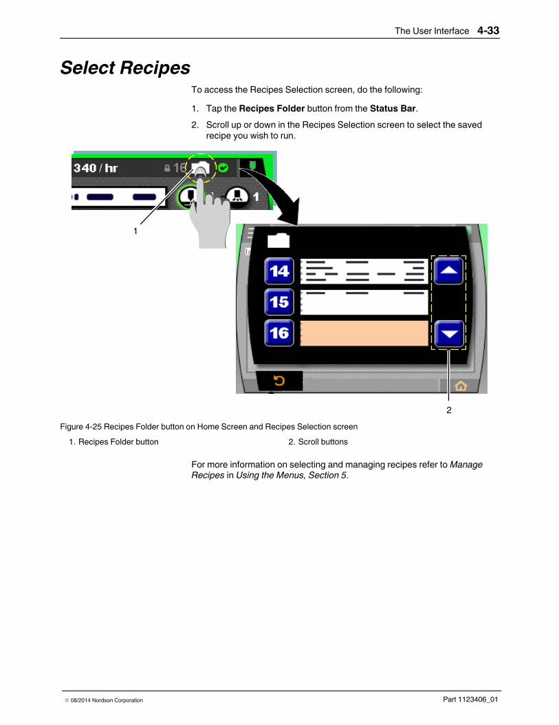
Select RecipesTo access the Recipes Selection screen, do the following:1. Tap the Recipes Folder button from the Status Bar.2. Scroll up or down in the Recipes Selection screen to select the saved
recipe you wish to run.
1
2Figure 4-25 Recipes Folder button on Home Screen and Recipes Selection screen
1. Recipes Folder button 2. Scroll buttons
For more information on selecting and managing recipes refer toManageRecipes in Using the Menus, Section 5.
The User Interface4-34
Part 1123406_01 E 08/2014 Nordson Corporation
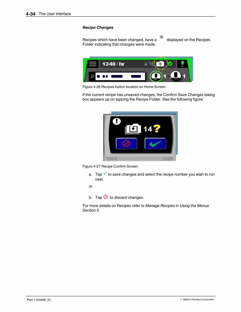
Recipe Changes
Recipes which have been changed, have a : displayed on the RecipesFolder indicating that changes were made.
:
Figure 4-26 Recipes button location on Home Screen
If the current recipe has unsaved changes, the Confirm Save Changes dialogbox appears up on tapping the Recipe Folder. See the following figure:
Figure 4-27 Recipe Confirm Screen
a. Tap to save changes and select the recipe number you wish to runnext.
or
b. Tap to discard changes.For more details on Recipes refer toManage Recipes in Using the MenusSection 5.

Using the Menus 5-1
Part 1123406_01E 08/2014 Nordson Corporation
Section 5Using the Menus
WARNING! Allow only qualified personnel to perform the following tasks.Follow the safety instructions in this document and all other relateddocumentation.
OverviewUse the Main Menu screen components to navigate, configure, and fine tunethe pattern controller settings.
1
3
45
6
7 2
Figure 5-1 Main Menu screen1 Main Menu screen2 Manage Recipes screen3 Tools Menu
4 Pressure Run-up screen5 Password lock/unlock screen6 System Settings Menu
7 Purge screen

Using the Menus5-2
Part 1123406_01 E 08/2014 Nordson Corporation
What you can do from the Main MenuSee Figure 5-1 for the location of the Main Menu screen buttons.
Assign or Modify the System Settings MenuButton Function
(Item 6 inFigure 5-1)
Tap to access the System Settings Menu to set or modifythe following functionalities:
a Languageb Encoderc Units/Scaled Componentse Inputf Outputg Machine Settings
Assign or Modify the Tools MenuButton Function
(Item 3 inFigure 5-1)
Tap to access the Tools Menu to set or modify thefollowing functionalities:
a Backup and Restoreb Clean Screenc System Informationd Message Loge Self Test
Assign or Modify the Purge MenuButton Function
(Item 7 inFigure 5-1)
S Purge any single applicatorS Hammer (fast cycle) any single applicatorS Flush any combination of applicators
Using the Menus 5-3
Part 1123406_01E 08/2014 Nordson Corporation
See Figure 5-1 for the location of the Main Menu screen buttons.
Assign or Modify the Pressure Run-up ScreenButton Function
(Item 4 inFigure 5-1)
Tap to access the Pressure Run-up screen to regulate thesystem pressure to maintain proper adhesive volumeduring line speed changes. This menu is used to set thetwo-point linear pressure profile.
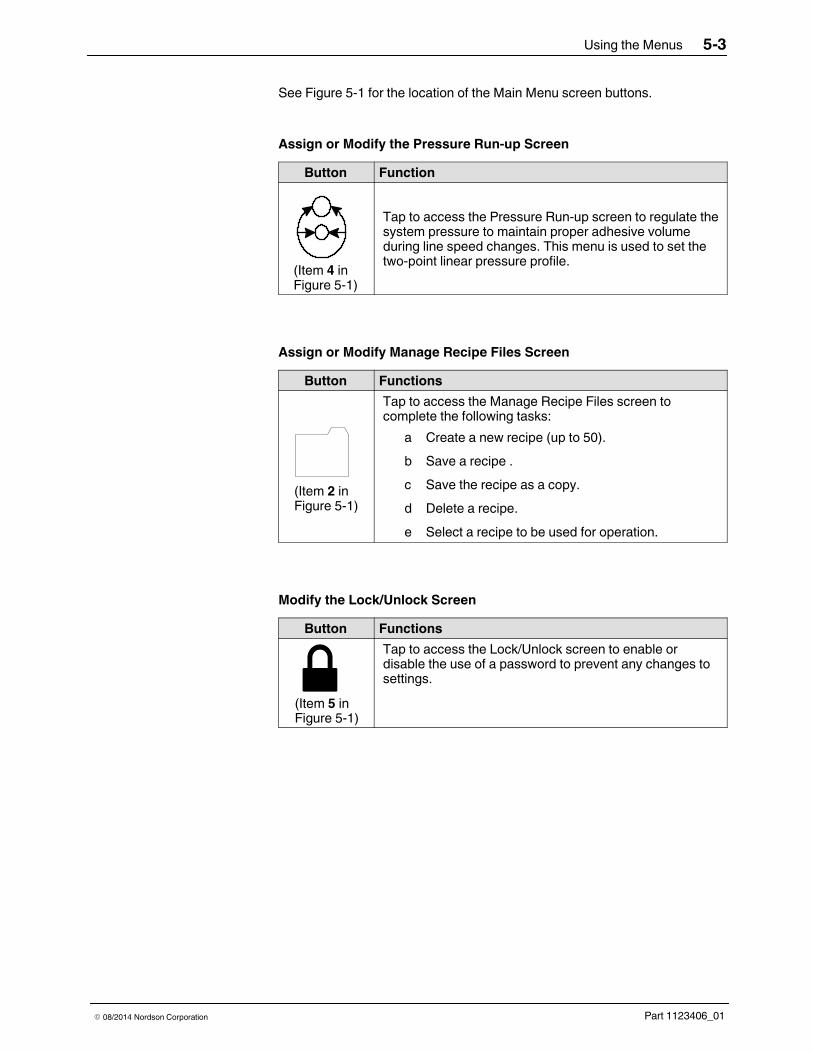
Assign or Modify Manage Recipe Files ScreenButton Functions
(Item 2 inFigure 5-1)
Tap to access the Manage Recipe Files screen tocomplete the following tasks:
a Create a new recipe (up to 50).b Save a recipe .c Save the recipe as a copy.d Delete a recipe.e Select a recipe to be used for operation.
Modify the Lock/Unlock ScreenButton Functions
(Item 5 inFigure 5-1)
Tap to access the Lock/Unlock screen to enable ordisable the use of a password to prevent any changes tosettings.

Using the Menus5-4
Part 1123406_01 E 08/2014 Nordson Corporation
Purge ApplicatorsUse this screen to regularly purge, flush, or hammer the applicators to allowthem to remain free of residue or any build up.
NOTE: All purge, hammer, and flush functions shut off when leaving thePurge menu.
Or
1 2 3
4Figure 5-2 Purge screen
1 Purge 2 Hammer 3 Flush 4 Applicator buttons
NOTE: The applicator button is grey when it is not installed.

Using the Menus 5-5
Part 1123406_01E 08/2014 Nordson Corporation
PurgeSelect Purge for hot melt adhesives. This mode removes trapped air ormaterial from the adhesive applicator or nozzle, or relieves system pressurewhen the applicator is turned on.
1. Hold a specific applicator button for purging.2. Release the applicator button to stop purging.
HammerSelect Hammer to allow the applicator output to actuate rapidly.
1. Hold a specific applicator button for hammering.2. Release the applicator button to stop hammering.
FlushSelect Flush to open one or more applicators for an extended period.
1. Tap the applicator button to turn on a specific applicator. Multipleapplicators may be flushed by tapping specific buttons.
2. Tap the applicator button again to stop flushing.NOTE: All purge, flush, and hammer functions stop when leaving thisscreen.

Using the Menus5-6
Part 1123406_01 E 08/2014 Nordson Corporation
Manage RecipesUse recipes to save and manage adhesive pattern settings for easy recallwhen you produce the same products in the future. Each recipe savedcontains details such as pattern types, applicator settings, and triggersettings. As many as 50 recipes can be saved.
The Recipes button located in the top navigation bar of the screen navigatesto two different Recipe Management screens.
Figure 5-3 Recipes button location on Home Screen- Tap the button for Recipe Quick Change- Hold the button to Manage Recipe Files
Selecting Multiple RecipesTo enable the use of multiple recipes, do the following:1. Go to the System SettingsMenu.2. Tap the Machine Settings button.3. Tap to use Multiple Recipe Files.
For additional details on selecting a single recipe or multiple recipes refertoMachine Settings in System Settings given later in this section.
Figure 5-4 Single and Multiple recipes selection buttons on the Machine Settings screen

Using the Menus 5-7
Part 1123406_01E 08/2014 Nordson Corporation
Recipe Quick ChangeTo access the Recipes Selection screen, do the following:1. Tap the Recipes Folder button from the Status Bar.2. Scroll up or down in the Recipes Selection screen to select the saved
recipe you wish to run.
1
2Figure 5-5 Recipes Folder button on Home Screen and Recipes Selection screen
1 Recipes Folder button 2 Scroll buttons

Using the Menus5-8
Part 1123406_01 E 08/2014 Nordson Corporation
Recipe Changes
Recipes which have been changed, have a : displayed on the RecipesFolder indicating that changes were made.
:
Figure 5-6 Recipes button location on Home Screen
If the current recipe has unsaved changes, the Confirm Save Changes dialogbox appears, see the following figure:
Figure 5-7 Save Recipe Confirm Screen
a. Tap to save changes and select the recipe number you wish to runnext.
or
b. Tap to cancel.NOTE: Changes will not be saved if a new recipe is opened.

Using the Menus 5-9
Part 1123406_01E 08/2014 Nordson Corporation
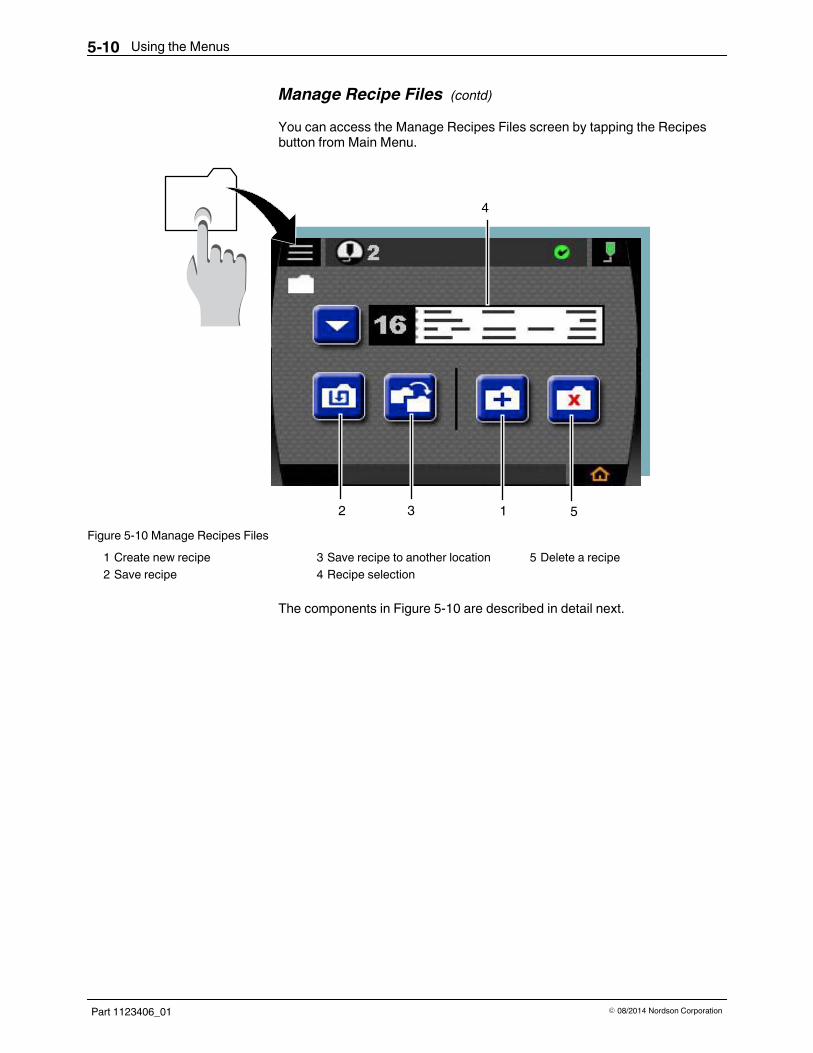
Manage Recipe FilesYou can Manage Recipe Files from the Main Menu:S Tap the Recipes button fromMain Menu
Figure 5-8 Recipes button on Main MenuOr
S Hold the Recipes button from the Home Screen
Figure 5-9 Recipes button on Home Screen
Using the Menus5-10
Part 1123406_01 E 08/2014 Nordson Corporation
Manage Recipe Files (contd)
You can access the Manage Recipes Files screen by tapping the Recipesbutton from Main Menu.
4
12 3 5Figure 5-10 Manage Recipes Files
1 Create new recipe2 Save recipe
3 Save recipe to another location4 Recipe selection
5 Delete a recipe
The components in Figure 5-10 are described in detail next.
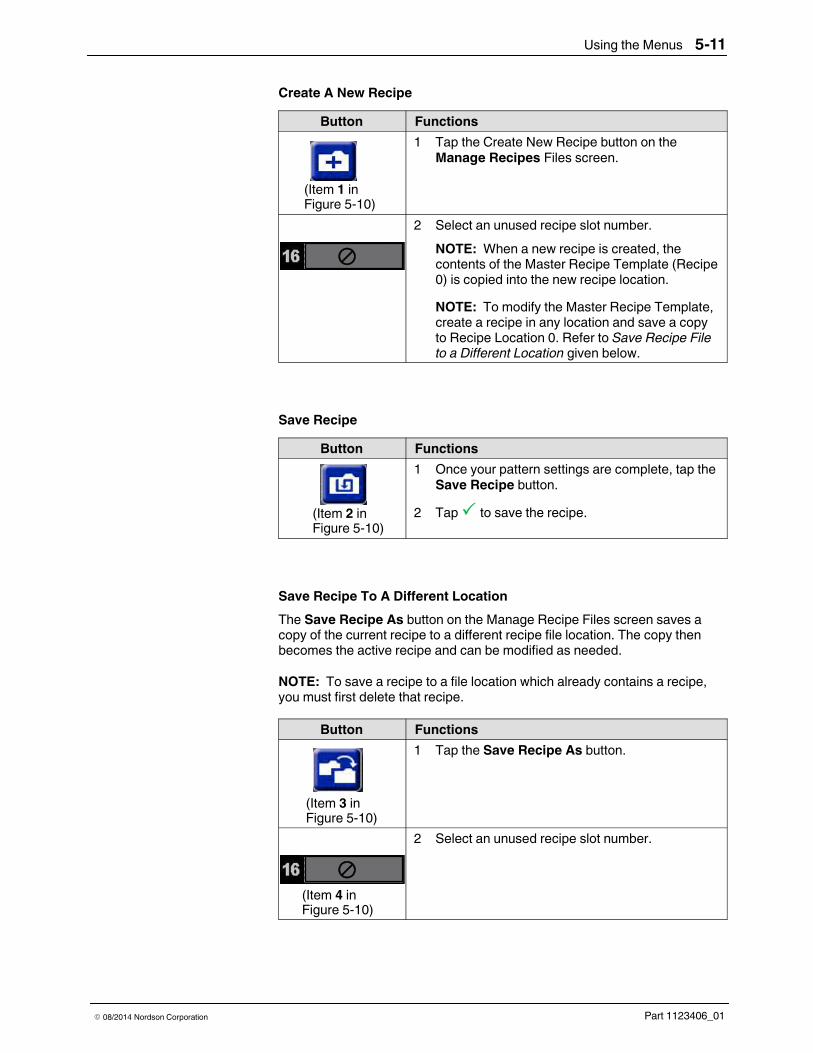
Using the Menus 5-11
Part 1123406_01E 08/2014 Nordson Corporation
Create A New RecipeButton Functions
(Item 1 inFigure 5-10)
1 Tap the Create New Recipe button on theManage Recipes Files screen.
2 Select an unused recipe slot number.NOTE: When a new recipe is created, thecontents of the Master Recipe Template (Recipe0) is copied into the new recipe location.NOTE: To modify the Master Recipe Template,create a recipe in any location and save a copyto Recipe Location 0. Refer to Save Recipe Fileto a Different Location given below.
Save RecipeButton Functions
(Item 2 inFigure 5-10)
1 Once your pattern settings are complete, tap theSave Recipe button.
2 Tap to save the recipe.
Save Recipe To A Different LocationThe Save Recipe As button on the Manage Recipe Files screen saves acopy of the current recipe to a different recipe file location. The copy thenbecomes the active recipe and can be modified as needed.
NOTE: To save a recipe to a file location which already contains a recipe,you must first delete that recipe.
Button Functions
(Item 3 inFigure 5-10)
1 Tap the Save Recipe As button.
(Item 4 inFigure 5-10)
2 Select an unused recipe slot number.

Using the Menus5-12
Part 1123406_01 E 08/2014 Nordson Corporation
Select a Different Recipe To Run
Button Functions1 Tap the Recipe Selection arrow
button or the pattern thumbnailon the Manage Recipe Files.
2 Tap the arrow to scroll up ordown to view the saved recipes.
3 Tap an existing recipe you wantto use to run.NOTE: The displayautomatically returns to theHome Screen with the selectedrecipe as the active recipe.
Delete Recipe
Button Functions
(Item 5 inFigure 5-10)
1 Tap the Delete button.2 Tap the arrows to scroll up or
down to view the saved recipes.
3 Tap the recipe number button orpattern thumbnail of the recipeyou wish to delete.
4 Tap to accept the setting, ortap to cancel.
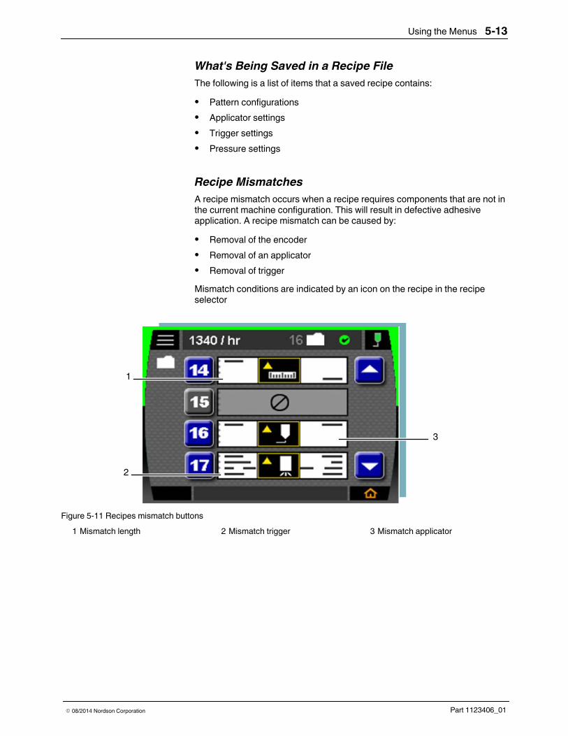
Using the Menus 5-13
Part 1123406_01E 08/2014 Nordson Corporation
What's Being Saved in a Recipe FileThe following is a list of items that a saved recipe contains:S Pattern configurationsS Applicator settingsS Trigger settingsS Pressure settings
Recipe MismatchesA recipe mismatch occurs when a recipe requires components that are not inthe current machine configuration. This will result in defective adhesiveapplication. A recipe mismatch can be caused by:S Removal of the encoderS Removal of an applicatorS Removal of triggerMismatch conditions are indicated by an icon on the recipe in the recipeselector
1
2
3
Figure 5-11 Recipes mismatch buttons1 Mismatch length 2 Mismatch trigger 3 Mismatch applicator

Using the Menus5-14
Part 1123406_01 E 08/2014 Nordson Corporation
Recipe Mismatches (contd)Mismatch Button Description
(Item 1 inFigure 5-11)
This button appears when an encoder (differentmachine mode) has been removed and/or added.
(Item 2 inFigure 5-11)
This button appears when an applicator that isrequired by a recipe has been removed.
(Item 3 inFigure 5-11)
This button appears when a trigger that is requiredby a recipe has been removed.
For Fixing Recipe Mismatch Problems refer to Troubleshooting.

Using the Menus 5-15
Part 1123406_01E 08/2014 Nordson Corporation
Remote Control Recipe SelectionRecipe selection can be controlled from the PLC rather than within thecontroller system. You will need to order a software license for this remotecontrol ability if it is not included in your system. Refer to Parts, Section 8 forthe software license part numbers.
Tap the check box on the Input screen to enable the Remote RecipeSelection feature. See the following figure for the remote recipes enablecheck box.
Figure 5-12 Enable remote recipes on the Input screen
NOTE: You can select as many as 31 remote recipes.For more details refer to Inputs in System Settings given later in this section.
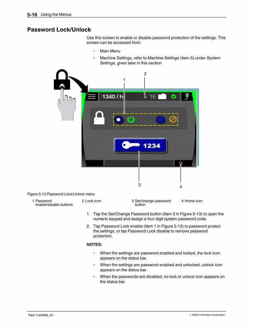
Using the Menus5-16
Part 1123406_01 E 08/2014 Nordson Corporation
Password Lock/UnlockUse this screen to enable or disable password protection of the settings. Thisscreen can be accessed from:
- Main Menu- Machine Settings, refer toMachine Settings (item 5) under System
Settings, given later in this section
1
43
2
Figure 5-13 Password Lock/Unlock menu1 Passwordenable/disable buttons
2 Lock icon 3 Set/change passwordbutton
4 Home icon
1. Tap the Set/Change Password button (item 3 in Figure 5-13) to open thenumeric keypad and assign a four digit system password code.
2. Tap Password Lock enable (item 1 in Figure 5-13) to password protectthe settings, or tap Password Lock disable to remove passwordprotection.
NOTES:- When the settings are password enabled and locked, the lock icon
appears on the status bar.- When the settings are password enabled and unlocked, unlock icon
appears on the status bar.- When the passwords are disabled, no lock or unlock icon appears on
the status bar.
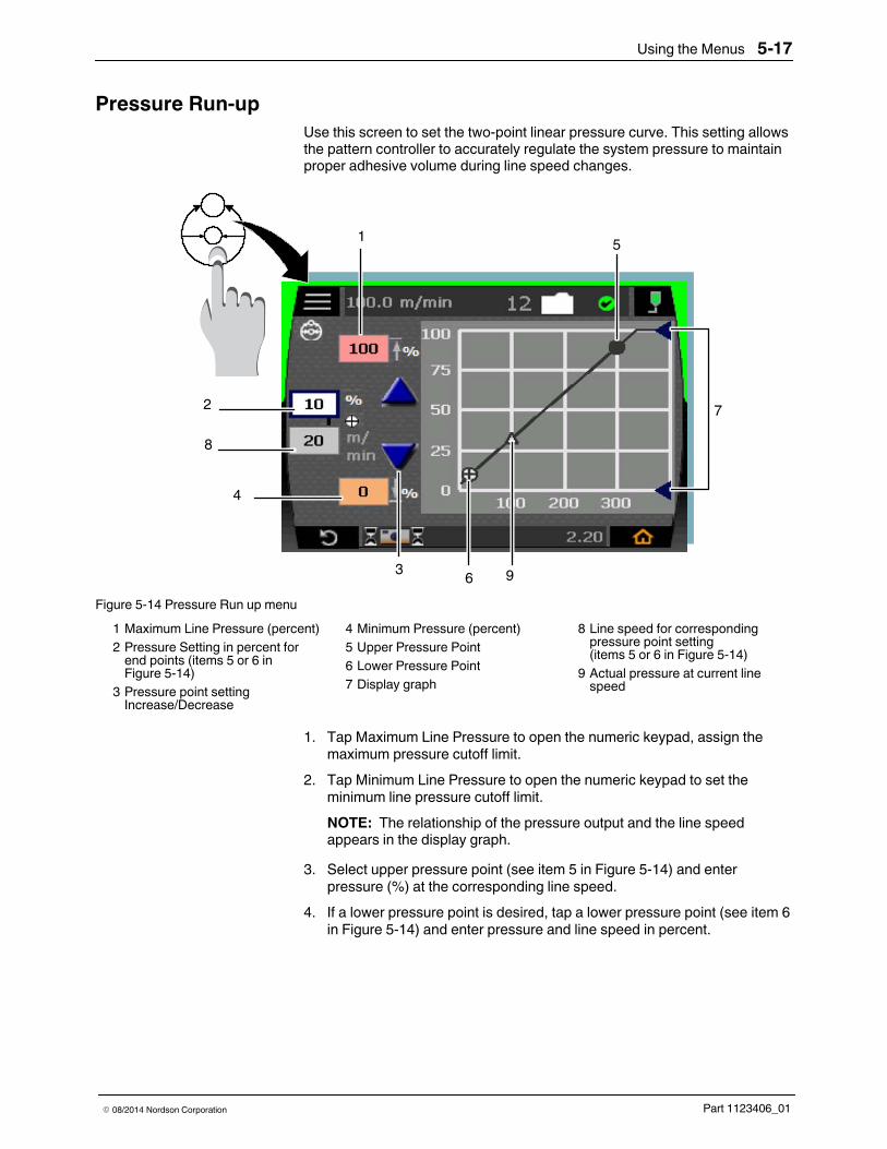
Using the Menus 5-17
Part 1123406_01E 08/2014 Nordson Corporation
Pressure Run-upUse this screen to set the two-point linear pressure curve. This setting allowsthe pattern controller to accurately regulate the system pressure to maintainproper adhesive volume during line speed changes.
1
2
8
4
6
7
3
5
9Figure 5-14 Pressure Run up menu
1 Maximum Line Pressure (percent)2 Pressure Setting in percent forend points (items 5 or 6 inFigure 5-14)
3 Pressure point settingIncrease/Decrease
4 Minimum Pressure (percent)5 Upper Pressure Point6 Lower Pressure Point7 Display graph
8 Line speed for correspondingpressure point setting(items 5 or 6 in Figure 5-14)
9 Actual pressure at current linespeed
1. Tap Maximum Line Pressure to open the numeric keypad, assign themaximum pressure cutoff limit.
2. Tap Minimum Line Pressure to open the numeric keypad to set theminimum line pressure cutoff limit.NOTE: The relationship of the pressure output and the line speedappears in the display graph.
3. Select upper pressure point (see item 5 in Figure 5-14) and enterpressure (%) at the corresponding line speed.
4. If a lower pressure point is desired, tap a lower pressure point (see item 6in Figure 5-14) and enter pressure and line speed in percent.

Using the Menus5-18
Part 1123406_01 E 08/2014 Nordson Corporation
Tools MenuUse the components in this screen to setup administrative tasks for thesystem.
1 2
345Figure 5-15 Tools Menu components
1 System Backup/Restore/Reset2 Clean Screen
3 Self Test4 Message Log
5 System Information
The components in Figure 5-15 are described in details in Tools MenuComponents.
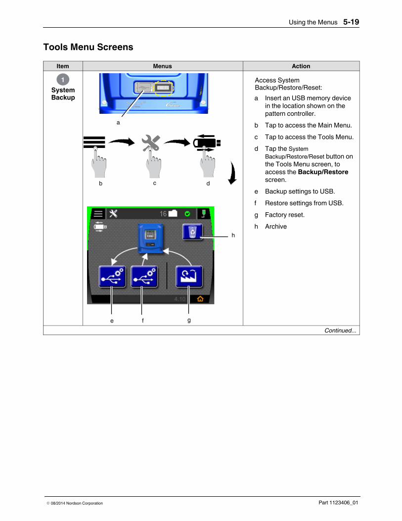
Using the Menus 5-19
Part 1123406_01E 08/2014 Nordson Corporation
Tools Menu ScreensItem Menus Action
SystemBackup
1
a
cb d
fe g
h
Access SystemBackup/Restore/Reset:a Insert an USB memory device
in the location shown on thepattern controller.
b Tap to access the Main Menu.c Tap to access the Tools Menu.d Tap the System
Backup/Restore/Reset button onthe Tools Menu screen, toaccess the Backup/Restorescreen.
e Backup settings to USB.f Restore settings from USB.g Factory reset.h Archive
Continued...

Using the Menus5-20
Part 1123406_01 E 08/2014 Nordson Corporation
Tools Menu Screens (contd)
Item Menus ActionBackup
Settings toUSB
a
Backup to USBSpectra 30
c
b
d
Spectra 30_Backup_2014428_1912.nor
Spectra 30_Backup_2014428_1912.nor
a Tap Backup settings to USBbutton on the SystemBackup/Restore screen.
b Tap to Save to USB. Thisallows files to be copied to USBdevice for backup purposes.NOTE: Tap to cancel/bypassthis functionality.
c If you select, the progress barscreen appears to indicate thatthe files are being copied into theUSB device.
d Tap to close the dialog box.NOTE: To check if the files havebeen saved to the USB devicedo the following:
- Plug the device into thecomputer.
- Open the folder calledBackup. The files followthis naming convention:
Spectra30_Backup_YearMonthDate.nor
The file name of the backupfile is displayed for futurereferences. Backup files havethe extension .nor
Continued...

Using the Menus 5-21
Part 1123406_01E 08/2014 Nordson Corporation
Item Menus ActionRestoresettingsfrom USB
aSelect which file to restore:Spectra30_Backup_2014428_1733.norSpectra30_Backup_2014428_1849.norSpectra30_Backup_2014428_1912.nor
Cancel Restore
c
b
d
Backup to USBSpectra 30
Spectra 30_Backup_2014428_1912.nor
e
Spectra 30_Backup_2014428_1912.nor
a Tap Restore from USB buttonon the Backup/Restore screen.
b A screen with a list of filesappears. Tap to select the filethat you want to restore, andthen tap Restore.NOTE: Tap Cancel tocancel/bypass this functionality.
c Tap to allow the selected filesto be restored from the USBdevice to the pattern controller.
d The progress bar screenappears to indicate that the filesare being copied to the patterncontroller.
e Tap to close the dialog box.
Continued...
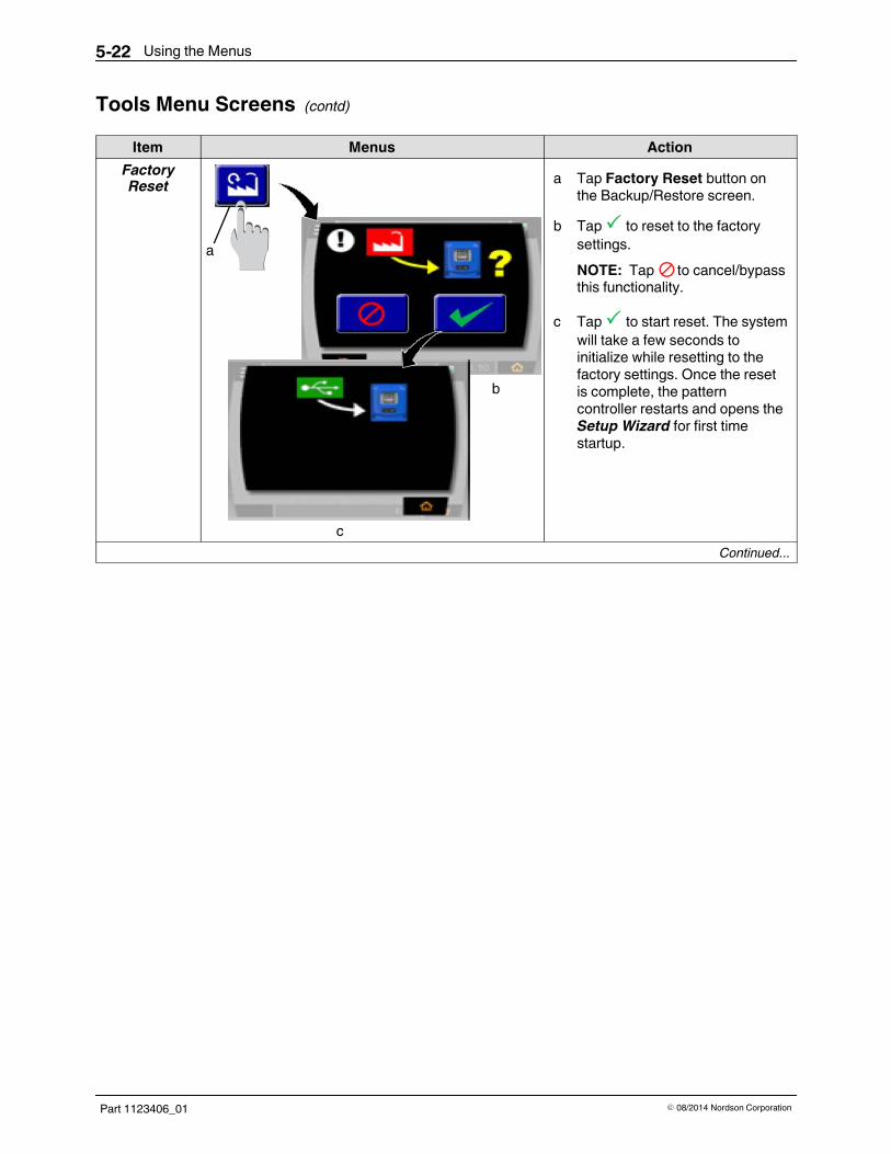
Using the Menus5-22
Part 1123406_01 E 08/2014 Nordson Corporation
Tools Menu Screens (contd)
Item Menus ActionFactoryReset
a
c
b
a Tap Factory Reset button onthe Backup/Restore screen.
b Tap to reset to the factorysettings.NOTE: Tap to cancel/bypassthis functionality.
c Tap to start reset. The systemwill take a few seconds toinitialize while resetting to thefactory settings. Once the resetis complete, the patterncontroller restarts and opens theSetup Wizard for first timestartup.
Continued...
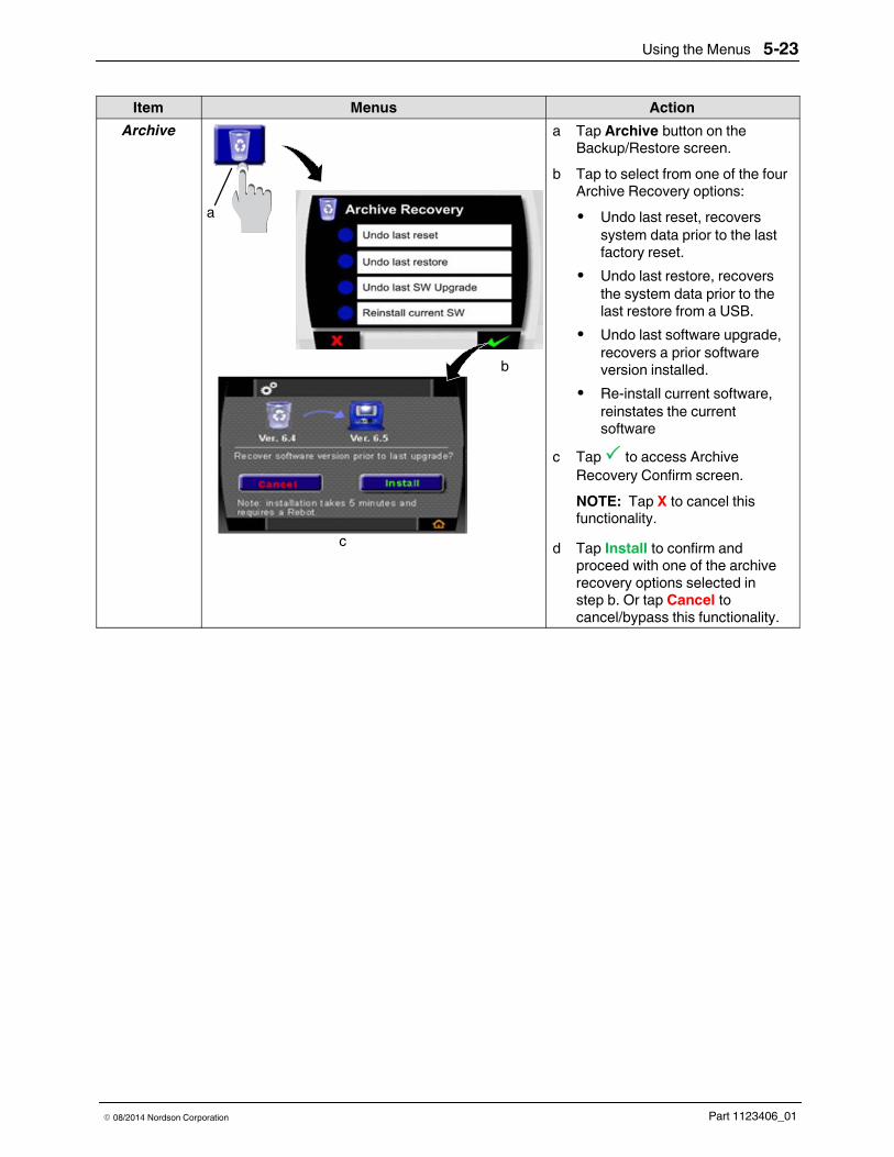
Using the Menus 5-23
Part 1123406_01E 08/2014 Nordson Corporation
ActionMenusItemArchive
a
c
b
a Tap Archive button on theBackup/Restore screen.
b Tap to select from one of the fourArchive Recovery options:S Undo last reset, recovers
system data prior to the lastfactory reset.
S Undo last restore, recoversthe system data prior to thelast restore from a USB.
S Undo last software upgrade,recovers a prior softwareversion installed.
S Re-install current software,reinstates the currentsoftware
c Tap to access ArchiveRecovery Confirm screen.NOTE: Tap X to cancel thisfunctionality.
d Tap Install to confirm andproceed with one of the archiverecovery options selected instep b. Or tap Cancel tocancel/bypass this functionality.

Using the Menus5-24
Part 1123406_01 E 08/2014 Nordson Corporation
Tools Menu Screens (contd)
Item Menus Action
CleanScreen
2
ba
c
a Tap the Clean Screen button fortouch screen maintenance.
b Use the Brightness Slider toadjust the touch screenbrightness.
c Tap the Clean Screen button todisable the touch functionality.After 30 seconds, the touchfunctionality is enabled.

Using the Menus 5-25
Part 1123406_01E 08/2014 Nordson Corporation
Item Menus Action
Self Test3
a
a Tap the Self Test button to testthe system.Self test checks the system'sinput and output functions.
Run SelfTest
b
b Tap the Self Test button tobegin the self-test process.NOTE: If the self-test passes,the message shown in figure onthe left appears.If the self-test fails, an alert orfault occurs detailing theproblem. For more details referto Troubleshooting,Section 6.
Continued...

Using the Menus5-26
Part 1123406_01 E 08/2014 Nordson Corporation
Tools Menu Screens (contd)
Item Menus ActionSave TestResults to aUSB Drive
b
a
Spectra 30_2014428_1912.nor
a Insert an USB drive in the frontpanel of the pattern controller.
b Tap this button to save the testresults to an USB drive.
c Tap to close the dialog box.
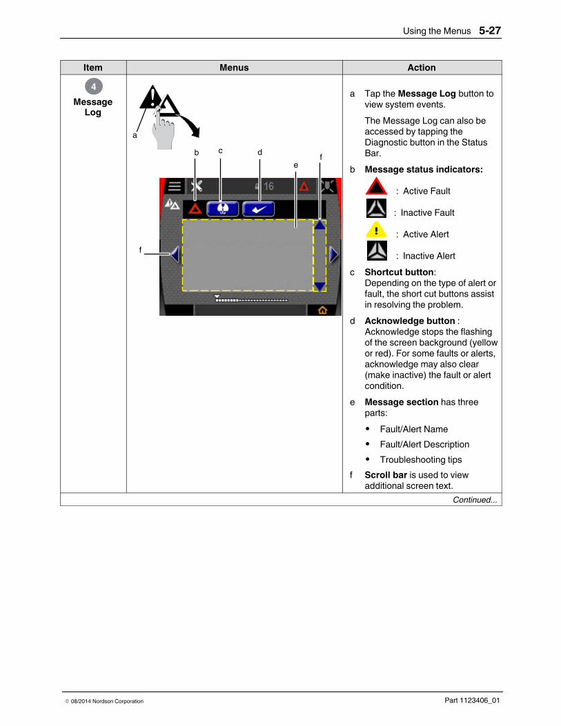
Using the Menus 5-27
Part 1123406_01E 08/2014 Nordson Corporation
Item Menus Action
MessageLog
4
ba
c de
f
f
a Tap the Message Log button toview system events.The Message Log can also beaccessed by tapping theDiagnostic button in the StatusBar.
b Message status indicators:
: Active Fault
: Inactive Fault
: Active Alert
: Inactive Alertc Shortcut button:
Depending on the type of alert orfault, the short cut buttons assistin resolving the problem.
d Acknowledge button :Acknowledge stops the flashingof the screen background (yellowor red). For some faults or alerts,acknowledge may also clear(make inactive) the fault or alertcondition.
e Message section has threeparts:S Fault/Alert NameS Fault/Alert DescriptionS Troubleshooting tips
f Scroll bar is used to viewadditional screen text.
Continued...
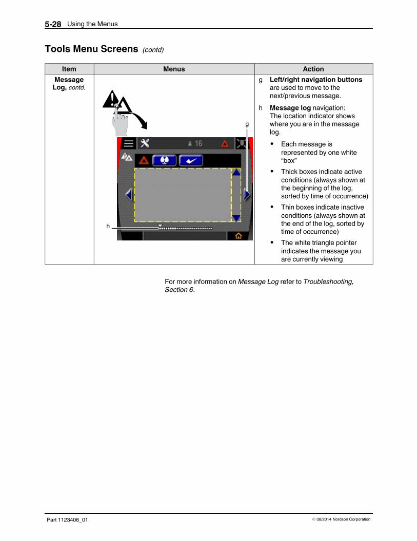
Using the Menus5-28
Part 1123406_01 E 08/2014 Nordson Corporation
Tools Menu Screens (contd)
Item Menus ActionMessageLog, contd.
g
h
g Left/right navigation buttonsare used to move to thenext/previous message.
h Message log navigation:The location indicator showswhere you are in the messagelog.S Each message is
represented by one white“box”
S Thick boxes indicate activeconditions (always shown atthe beginning of the log,sorted by time of occurrence)
S Thin boxes indicate inactiveconditions (always shown atthe end of the log, sorted bytime of occurrence)
S The white triangle pointerindicates the message youare currently viewing
For more information onMessage Log refer to Troubleshooting,Section 6.

Using the Menus 5-29
Part 1123406_01E 08/2014 Nordson Corporation
Item Menus Action
SystemInformation
5
a
b
Software Versions:Panel 4.068
a Tap the System Informationbutton to view details about thesystem.
b Tap LIC. button to upgrade thesystem with add-on features.The following add-on featuresare available:S EncoderS Pressure/Run-upS Remote recallThe add-on features havesoftware licenses, which can beordered by specific partnumbers. Refer to Parts,Section 8 for the softwarelicense part numbers.
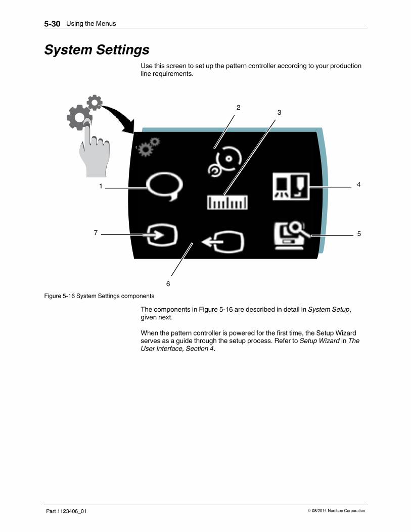
Using the Menus5-30
Part 1123406_01 E 08/2014 Nordson Corporation
System SettingsUse this screen to set up the pattern controller according to your productionline requirements.
3
5
4
6
2
1
7
Figure 5-16 System Settings components
The components in Figure 5-16 are described in detail in System Setup,given next.
When the pattern controller is powered for the first time, the Setup Wizardserves as a guide through the setup process. Refer to Setup Wizard in TheUser Interface, Section 4.

Using the Menus 5-31
Part 1123406_01E 08/2014 Nordson Corporation
System Setup ScreensItem Menu Action
Language1
a b
a Tap the Language button on theSystem Settings screen.
b Tap the scroll button to viewmore selections.
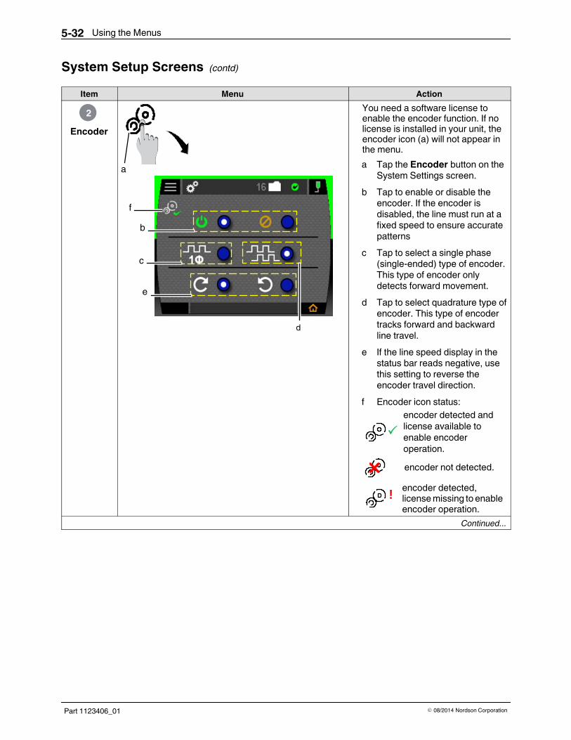
Using the Menus5-32
Part 1123406_01 E 08/2014 Nordson Corporation
System Setup Screens (contd)
Item Menu Action
Encoder2
b
c
d
a
e
f
You need a software license toenable the encoder function. If nolicense is installed in your unit, theencoder icon (a) will not appear inthe menu.a Tap the Encoder button on the
System Settings screen.b Tap to enable or disable the
encoder. If the encoder isdisabled, the line must run at afixed speed to ensure accuratepatterns
c Tap to select a single phase(single-ended) type of encoder.This type of encoder onlydetects forward movement.
d Tap to select quadrature type ofencoder. This type of encodertracks forward and backwardline travel.
e If the line speed display in thestatus bar reads negative, usethis setting to reverse theencoder travel direction.
f Encoder icon status:
!
encoder detected andlicense available toenable encoderoperation.encoder not detected.encoder detected,licensemissing to enableencoder operation.
Continued...

Using the Menus 5-33
Part 1123406_01E 08/2014 Nordson Corporation
Item Menu ActionExamples of Encoder Settings: Tap the button shown in the figure
on the left to select no encoder.
Tap the buttons shown in the figureon the left to select a single phaseencoder.
Tap the buttons shown in the figureon the left to select a quadratureencoder.

Using the Menus5-34
Part 1123406_01 E 08/2014 Nordson Corporation
System Setup Screens (contd)
Item Menu Action
Units/Scale
3
a b
c
d
10 a Tap the Units/Scale buttonon the System Settingsscreen.
b Select how you want toprogram the patterns:S ms (milliseconds)S mm (millimeter)S inch (in.)
c For Encoder icon status:
If you don’t use an encoder, scalingcan still be used to allow patterns tobe programmed in distance, but thescaling is only accurate at one linespeed.When you use an optional encoder,scaling ensures that the line speeddisplays correctly and thatprogrammed pattern measurementis accurate at all line speeds.
!
encoder detected andlicense available toenable encoderoperation.encoder not detected.encoder detected,licensemissing to enableencoder operation.
Continued...

Using the Menus 5-35
Part 1123406_01E 08/2014 Nordson Corporation
Item Menu Actiond Use one of the three methods of
scaling the pattern controller:Scale usingproductlength
101 Measure with the actual
product length in line wherethe trigger detects theproduct.
2 Tap to select scale byproduct length.
3 Tap to use a different triggerinput for lengthmeasurement.
4 Enter the measured productlength from step 1.
NOTE: The hourglass symbolappears until a product isdetected on the trigger input.5 Run at least one product past
the trigger.6 The system calculates the
resulting scale.Scale usingline speed
Make sure the line is running at aknown constant speed.1 Tap to select scale by line
speed.2 Enter the known line speed.NOTE: The system calculatesthe resulting scale.
Scalemanually
NOTE: Manual scaling isnormally used only with anencoder.1 Tap to scale manually.2 Enter the number of pulses
per millimeter (or per inch) ofline travel.
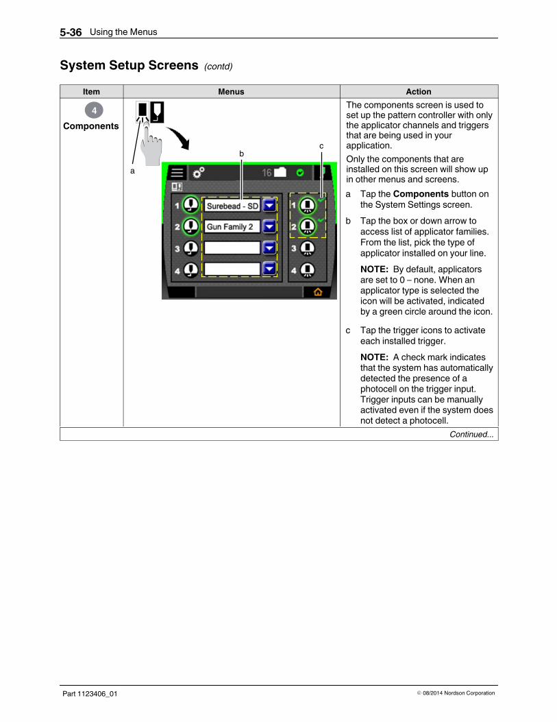
Using the Menus5-36
Part 1123406_01 E 08/2014 Nordson Corporation
System Setup Screens (contd)
Item Menus Action
Components4
ab
c
The components screen is used toset up the pattern controller with onlythe applicator channels and triggersthat are being used in yourapplication.Only the components that areinstalled on this screen will show upin other menus and screens.a Tap the Components button on
the System Settings screen.b Tap the box or down arrow to
access list of applicator families.From the list, pick the type ofapplicator installed on your line.NOTE: By default, applicatorsare set to 0 – none. When anapplicator type is selected theicon will be activated, indicatedby a green circle around the icon.
c Tap the trigger icons to activateeach installed trigger.NOTE: A check mark indicatesthat the system has automaticallydetected the presence of aphotocell on the trigger input.Trigger inputs can be manuallyactivated even if the system doesnot detect a photocell.
Continued...

Using the Menus 5-37
Part 1123406_01E 08/2014 Nordson Corporation
ActionMenusItemCompensation
a
b
c
d
Compensation values are setautomatically based on yourapplicator selection. The defaultvalues can be changed whennecessary.Compensation adjusts for anyshift in patterns as the line speedchanges from low to high. Thisshift is caused by the mechanicaldelays in the applicator. There isa separate setting for on-delay(see step b) and off-delay (seestep c).S If the patterns shift
backward as the linespeeds up, a largercompensation is needed
S If the pattern shifts forwardas the line speeds up, alower compensation valueis needed.
S If the pattern shifts in theleading edge (on-delay), itcan be adjustedindependently of the trailingedge (off-delay) of thepattern.
a Hold the Applicator buttonon the Components screen toaccess the Compensation menu.
b Tap numeric keypad to enter theleading edge compensation.
c Tap numeric keypad to enter thetrailing edge compensation.
d Tap to reset the compensation to thefactory default setting.
Continued...

Using the Menus5-38
Part 1123406_01 E 08/2014 Nordson Corporation
System Setup Screens (contd)
Item Menus ActionCompensation,
contd.Recommended settings:1 Set both compensation values
to zero.2 Apply an adhesive pattern at a
very low speed.3 Apply an adhesive pattern at
the highest normal run speed.4 Measure the shift in the leading
and trailing edge of the bead.5 Convert the pattern shift to time
(ms):
Metric:Edge shift (mm)*60 = Compensation (ms)Line Speed (m/min)
English:Edge shift in. = Compensation (ms)Line Speed (ft/min) *500
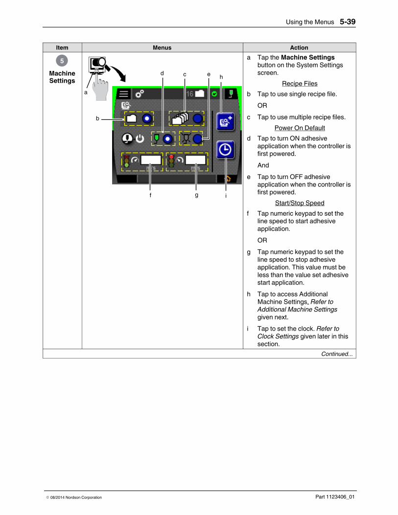
Using the Menus 5-39
Part 1123406_01E 08/2014 Nordson Corporation
Item Menus Action
MachineSettings
5
b
cd
f
a
e
g
h
i
a Tap the Machine Settingsbutton on the System Settingsscreen.
Recipe Filesb Tap to use single recipe file.
ORc Tap to use multiple recipe files.
Power On Defaultd Tap to turn ON adhesive
application when the controller isfirst powered.And
e Tap to turn OFF adhesiveapplication when the controller isfirst powered.
Start/Stop Speedf Tap numeric keypad to set the
line speed to start adhesiveapplication.OR
g Tap numeric keypad to set theline speed to stop adhesiveapplication. This value must beless than the value set adhesivestart application.
h Tap to access AdditionalMachine Settings. Refer toAdditional Machine Settingsgiven next.
i Tap to set the clock. Refer toClock Settings given later in thissection.
Continued...
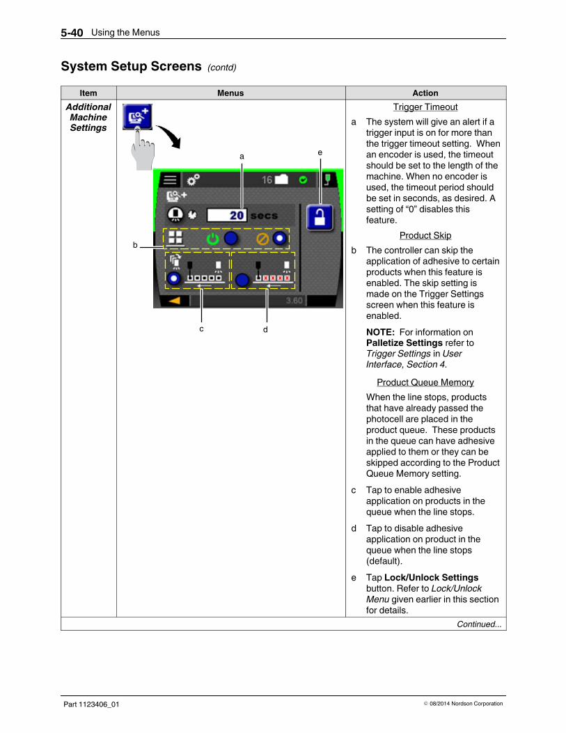
Using the Menus5-40
Part 1123406_01 E 08/2014 Nordson Corporation
System Setup Screens (contd)
Item Menus ActionAdditionalMachineSettings
e
b
c d
a
Trigger Timeouta The system will give an alert if a
trigger input is on for more thanthe trigger timeout setting. Whenan encoder is used, the timeoutshould be set to the length of themachine. When no encoder isused, the timeout period shouldbe set in seconds, as desired. Asetting of “0” disables thisfeature.
Product Skipb The controller can skip the
application of adhesive to certainproducts when this feature isenabled. The skip setting ismade on the Trigger Settingsscreen when this feature isenabled.NOTE: For information onPalletize Settings refer toTrigger Settings in UserInterface, Section 4.
Product Queue MemoryWhen the line stops, productsthat have already passed thephotocell are placed in theproduct queue. These productsin the queue can have adhesiveapplied to them or they can beskipped according to the ProductQueue Memory setting.
c Tap to enable adhesiveapplication on products in thequeue when the line stops.
d Tap to disable adhesiveapplication on product in thequeue when the line stops(default).
e Tap Lock/Unlock Settingsbutton. Refer to Lock/UnlockMenu given earlier in this sectionfor details.
Continued...

Using the Menus 5-41
Part 1123406_01E 08/2014 Nordson Corporation
Item Menus ActionClock
Settings
b
aThere are two sequential setupscreens:S DateS Time
a Date setup numeric padcomes first. Make sure tofollow one of the two datesetup formats.Tap to go to Time setupscreen
b Time setup numeric padcomes second. Make sure toselect one of the time setupformats.Tap to go back to MachineSettings screen

Using the Menus5-42
Part 1123406_01 E 08/2014 Nordson Corporation
System Setup Screens (contd)
Item Menu Function
Output6
f
b
c
d
ea
The pattern controller is equippedwith three standard outputs.Select an output to indicate that theline speed is above the start speed.a Tap the Output button on the
System Settings screen.b System Ready output signal
indicates that the system isfunctioning normally and ready toapply adhesive when enabled.The System Ready output canbe programmed to be:f: active high (24 VDC)ore: active low (0 VDC) when thesystem is ready.
c Alert output signal outputindicates that an Alert conditionis present. The Alert output canbe programmed to be:f: active high (24 VDC)ore: active low (0 VDC) when thesystem is ready.NOTE: Output can bereconfigured as a minimumspeed output using theAdvanced Setting Utilityavailable atwww.enordson.com/support.
d Fault/Machine Stop output is aSPDT(Single Pole DoubleThrow) dry contact output withboth normally open and normallyclosed contacts. Use this settingto set the power off conditioneither to fault (e) or no fault (f).
Continued...
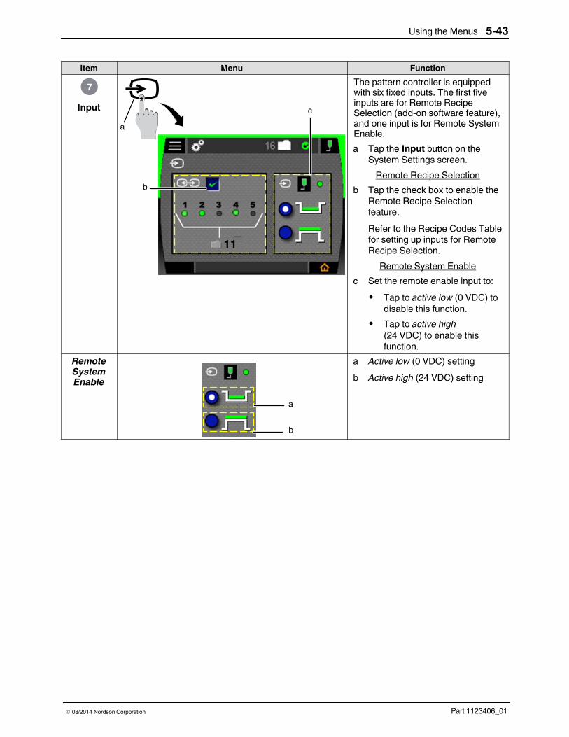
Using the Menus 5-43
Part 1123406_01E 08/2014 Nordson Corporation
Item Menu Function
Input7
ca
b
11
The pattern controller is equippedwith six fixed inputs. The first fiveinputs are for Remote RecipeSelection (add-on software feature),and one input is for Remote SystemEnable.a Tap the Input button on the
System Settings screen.Remote Recipe Selection
b Tap the check box to enable theRemote Recipe Selectionfeature.Refer to the Recipe Codes Tablefor setting up inputs for RemoteRecipe Selection.
Remote System Enablec Set the remote enable input to:S Tap to active low (0 VDC) to
disable this function.S Tap to active high
(24 VDC) to enable thisfunction.
RemoteSystemEnable
a
b
a Active low (0 VDC) settingb Active high (24 VDC) setting

Using the Menus5-44
Part 1123406_01 E 08/2014 Nordson Corporation
Remote Recipe Codes TableUse the codes in this table for setting up inputs for Remote Recipe Selection.
Recipe Number State ofInput 1-5 Recipe Number State of
Input 1-51 10000 16 000012 01000 17 100013 11000 18 010014 00100 19 110015 10100 20 001016 01100 21 101017 11100 22 011018 00010 23 111019 10010 24 0001110 01010 25 1001111 11010 26 0101112 00110 27 1101113 10110 28 0011114 01110 29 1011115 11110 30 0111116 00001 31 11111
Troubleshooting 6-1
Part 1123406_01E 08/2014 Nordson Corporation
Section 6Troubleshooting
WARNING! Allow only qualified personnel to perform the following tasks.Follow the safety instructions in this document and all other relateddocumentation.
WARNING! Observe all safety instructions and regulations concerningenergized unit components (active parts). Failure to observe may result in anelectric shock.
This section contains troubleshooting procedures. These procedures covercommon problems that you may encounter. If you cannot solve the problemwith the information given here, contact your local Nordson representative forhelp.
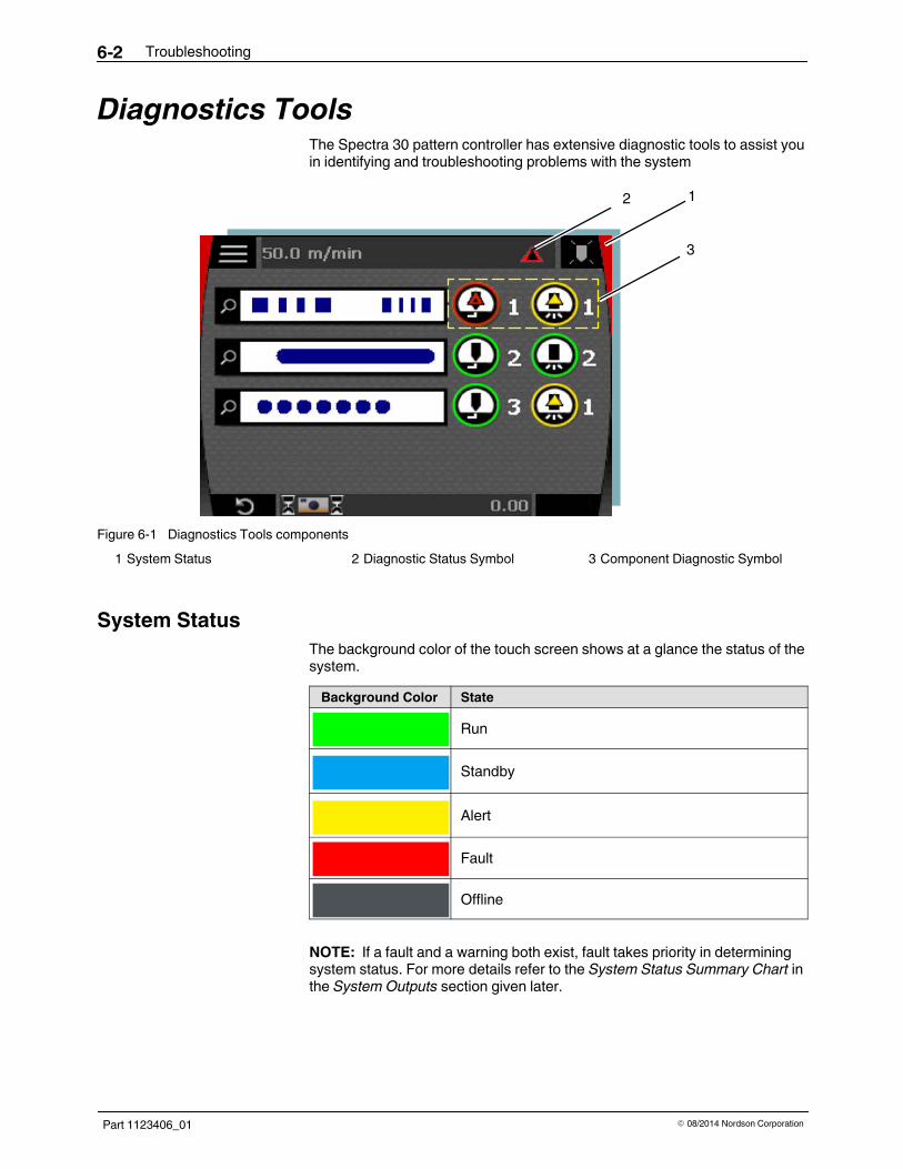
Troubleshooting6-2
Part 1123406_01 E 08/2014 Nordson Corporation
Diagnostics ToolsThe Spectra 30 pattern controller has extensive diagnostic tools to assist youin identifying and troubleshooting problems with the system
12
3
Figure 6-1 Diagnostics Tools components1 System Status 2 Diagnostic Status Symbol 3 Component Diagnostic Symbol
System StatusThe background color of the touch screen shows at a glance the status of thesystem.Background Color State
Run
Standby
Alert
Fault
Offline
NOTE: If a fault and a warning both exist, fault takes priority in determiningsystem status. For more details refer to the System Status Summary Chart inthe System Outputs section given later.
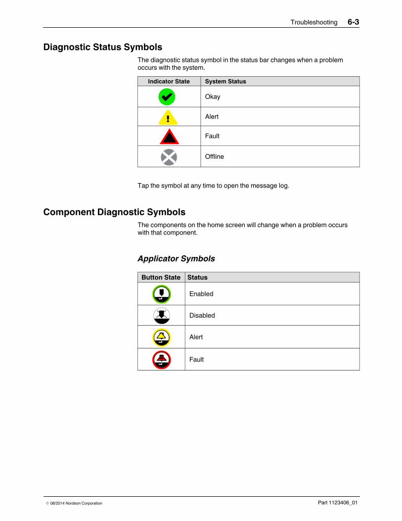
Troubleshooting 6-3
Part 1123406_01E 08/2014 Nordson Corporation
Diagnostic Status SymbolsThe diagnostic status symbol in the status bar changes when a problemoccurs with the system.
Indicator State System Status
Okay
Alert
Fault
Offline
Tap the symbol at any time to open the message log.
Component Diagnostic SymbolsThe components on the home screen will change when a problem occurswith that component.
Applicator SymbolsButton State Status
Enabled
Disabled
Alert
Fault

Troubleshooting6-4
Part 1123406_01 E 08/2014 Nordson Corporation
Trigger SymbolsButton State Status
Enabled
Alert
Fault
Pattern AlertsButton State Status
Display
Alert

Troubleshooting 6-5
Part 1123406_01E 08/2014 Nordson Corporation
Message Log1
2
3
2
4
5 67
8
Figure 6-2 Message Log components1 Message text2 Next/previous message button3 Message scroll indicator
4 Time/date stamp5 Message status indicator6 Acknowledge button
7 Shortcut button8 Scroll bar
Message TextEach Fault or Alert Message contains three parts:S Fault/Alert Name, a short nameS Fault/Alert Description, details of the conditionS Troubleshooting tips, suggested checks to resolve the problemNOTE: When necessary, use the scroll bar (item 8 in Figure 6-2) to seeadditional text. You can also slide your finger up and down in themessage box.

1 23
Troubleshooting6-6
Part 1123406_01 E 08/2014 Nordson Corporation
Message Scroll IndicatorThe Message Scroll Indicator (item 3 in Figure 6-2) shows the number ofactive and inactive messages and your current position in the log. Thisindicator contains a maximum of 25 messages.S Each tall block in the indicator shows an active fault or alert.S Each short block indicates shows an inactive fault or alert.S The triangle indicates your current position in the log.
Figure 6-3Message Scrollindicator
1 Tall block2 Short block3 Triangle
Message Status IndicatorsThe Message Status Indicator (item 5 in Figure 6-2) provides the type andstatus of each message:
Indicator State Status
Active Fault
Inactive Fault
Active Alert
Inactive Alert
NOTES:S Active Faults and Alerts are always sent to the beginning of the log,
and are sorted by time of occurrence.S Inactive Faults and Alerts are always sent to the end of the log, and
are sorted by time of occurrence.S To move to the next or previous message, use the left and right
message navigation buttons (item 2 in Figure 6-2).S Each message includes a time and date stamp of the message along
with a message code (item 4 in Figure 6-2).
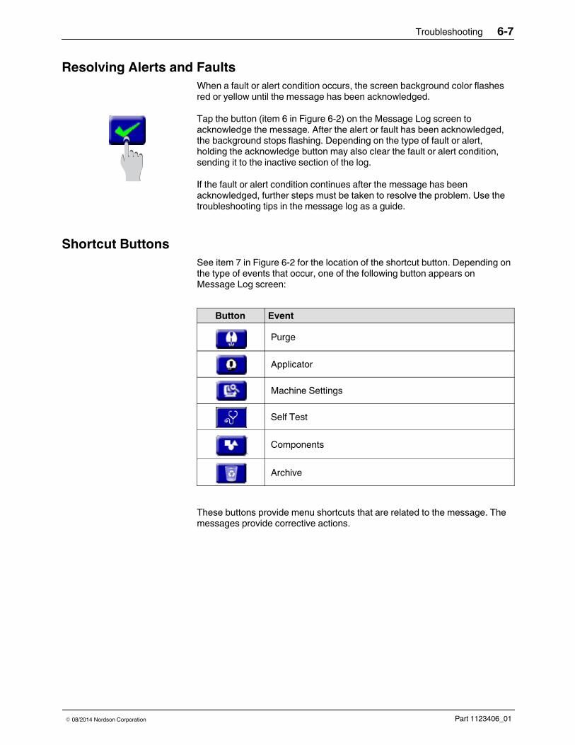
Troubleshooting 6-7
Part 1123406_01E 08/2014 Nordson Corporation
Resolving Alerts and FaultsWhen a fault or alert condition occurs, the screen background color flashesred or yellow until the message has been acknowledged.
Tap the button (item 6 in Figure 6-2) on the Message Log screen toacknowledge the message. After the alert or fault has been acknowledged,the background stops flashing. Depending on the type of fault or alert,holding the acknowledge button may also clear the fault or alert condition,sending it to the inactive section of the log.
If the fault or alert condition continues after the message has beenacknowledged, further steps must be taken to resolve the problem. Use thetroubleshooting tips in the message log as a guide.
Shortcut ButtonsSee item 7 in Figure 6-2 for the location of the shortcut button. Depending onthe type of events that occur, one of the following button appears onMessage Log screen:
Button Event
Purge
Applicator
Machine Settings
Self Test
Components
Archive
These buttons provide menu shortcuts that are related to the message. Themessages provide corrective actions.

Troubleshooting6-8
Part 1123406_01 E 08/2014 Nordson Corporation
System Self-TestA comprehensive system self-test is available that loops back outputs toinputs to verify the functions of controller board hardware. If the systempasses self-test, then the problem is most likely somewhere outside theSpectra 30 pattern controller system.
To access the Self Test screen, do the following:1. Tap the Tools button fromMain Menu.2. Tap the Self Test button.
1
2
Figure 6-4 Access Self Test screen1 Run self test button 2 Save results to a USB drive button

Troubleshooting 6-9
Part 1123406_01E 08/2014 Nordson Corporation
Self Test Screen Status
1 2Figure 6-5 Self Test screen status
1 Screen during self-test 2 Screen after a successful test
If the self-test fails, a fault or alert will be generated that will provide detailsabout the failure. Tap the Diagnostic icon in the Status Bar to go to theMessage Log.
100 m/min 16
Figure 6-6 Diagnostic icon on the Status Bar

Troubleshooting6-10
Part 1123406_01 E 08/2014 Nordson Corporation
System OutputsThere are three system outputs that provide system status:S Ready
An active output indicates that the pattern controller is ready for youto run the line and produce products. The Ready output is notaffected by Alerts or Standby.
S AlertAn active output indicates that an Alert condition exists. Alertconditions do not normally prevent you from producing products, butshould be investigated as soon as possible.
S Fault/Machine StopThe SPDT (Single Pole Double Throw) dry contact output is activatedwhile a Fault condition exists.
Refer to the System Status Summary Chart for an details.
NOTES:Refer to the Internal Wiring Details in Installation, Section 3 forinstructions on how to connect the system outputs.Refer to the System Settings in Using the Menus, Section 5 forinstructions on how to change the polarity of the system outputs.

Troubleshooting 6-11
Part 1123406_01E 08/2014 Nordson Corporation
System Status Summary Chart
System StateBack-groundColor
DescriptionSystem Outputs Adhesive Status
Ready AlertFault
MachineStop
DiagnosticIcon Status Icon
Run System is ready torun On Off Off On
AlertSystem is ready torun but a problemmay exist
On On Off On OR
Standby
System is ready torun but waiting forline speed toincrease orrelease fromremote input
On Off Off
StandbyRemoteinput
StandbyLineSpeed
FaultSerious problemcondition. Systemnot able to run
Off On/Off On Off
Offline
Adhesive OfforSet-up WizardBackup/restore isin progress/Software upgrade
Off Off Off Off
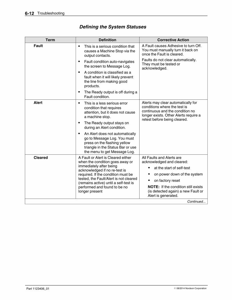
Troubleshooting6-12
Part 1123406_01 E 08/2014 Nordson Corporation
Defining the System Statuses
Term Definition Corrective ActionFault S This is a serious condition that
causes a Machine Stop via theoutput contacts.
S Fault condition auto-navigatesthe screen to Message Log.
S A condition is classified as afault when it will likely preventthe line from making goodproducts.
S The Ready output is off during aFault condition.
A Fault causes Adhesive to turn Off.You must manually turn it back ononce the Fault is cleared.Faults do not clear automatically.They must be tested oracknowledged.
Alert S This is a less serious errorcondition that requiresattention, but it does not causea machine stop.
S The Ready output stays onduring an Alert condition.
S An Alert does not automaticallygo to Message Log. You mustpress on the flashing yellowtriangle in the Status Bar or usethe menu to get Message Log.
Alerts may clear automatically forconditions where the test iscontinuous and the condition nolonger exists. Other Alerts require aretest before being cleared.
Cleared A Fault or Alert is Cleared eitherwhen the condition goes away orimmediately after beingacknowledged if no re-test isrequired. If the condition must betested, the Fault/Alert is not cleared(remains active) until a self-test isperformed and found to be nolonger present
All Faults and Alerts areacknowledged and cleared:S at the start of self-testS on power down of the systemS on factory resetNOTE: If the condition still exists(is detected again) a new Fault orAlert is generated.
Continued...
Troubleshooting 6-13
Part 1123406_01E 08/2014 Nordson Corporation
Term Definition Corrective ActionActive/Inactive S A Fault/Alert that has been
cleared is said to be Inactive.S A Fault/Alert that is still present
or has not been retested is saidto be Active. Active Faults andAlerts will appear first in themessage log, sorted by time ofoccurrence.
S Inactive Faults and Alertsappear after Active ones, alsosorted by time of occurrence.
S The Message Log contains amaximum of 25 messages andolder messages are pushed outof the log as new ones enter.
Factory reset clears the log of allcontents. The No Faults or Alertsmessage is displayed after FactoryReset until the first Alert or Faultoccurs.

Troubleshooting6-14
Part 1123406_01 E 08/2014 Nordson Corporation
When the System Fails to Start UpWARNING! Allow only qualified personnel to perform the following tasks.Follow the safety instructions in this document and all other relateddocumentation.
WARNING! The power supply is electrically energized and presents a shockhazard. Use caution while performing the troubleshooting steps below
The following tables provide some potential causes for a system failing topower up successfully.
Refer to System Schematics in Specifications section.
Controller Board IssuesProblem Controller Board Corrective Action
1. Missing AC Input Power orBlown Fuse
a
bc d
Note the following componentson the Controller Board:
a JP16b DS17c F2d F3
AC input power is supplied to thesystem continually on terminalblock JP16. The presence ofpower can be confirmed usingthe neon lamp DS17. If DS17 isnot lit, check fuses F2 and F3 forcontinuity and replace ifnecessary.
Continued...

Troubleshooting 6-15
Part 1123406_01E 08/2014 Nordson Corporation
Problem Controller Board Corrective Action2. Controller Board Fails toStart Up
a
b
Note the following componentson the Controller Board:
a DS14b DS15
The control switch on the front ofthe pattern controller switchespower from the 24VDC PowerSupply to the Controller Boardand the LCD touch screen. Referto the System Schematic inSpecifications, Section 7.Power to the Controller Boardcan be observed by DS14 in theupper right corner of the board(item a).Power for the CPU (processor) isderived from the 24VDC with anon-board regulator on theController Board. CPUPower is indicated by DS15 (b).For the Controller Board to run,both CPU power and24 VDC power LEDs must be lit.
Confirm Power to Touch Screen
abcd
e
Note the following componentson the Controller Board:
a JP8b JP7c Comd 24 VDCe F1
Power to the Touch Screen canbe confirmed by the screen beinglit.S Check for 24 VDC input
power at JP7 between pins 1and 3 as shown in the figureon the left.
S If 24 VDC is present, checkfuse F1 for continuity andreplace if necessary.
S If 24VDC is not present,check the output voltage ofthe Power Supply as shown inthe figure on the left.
Continued...
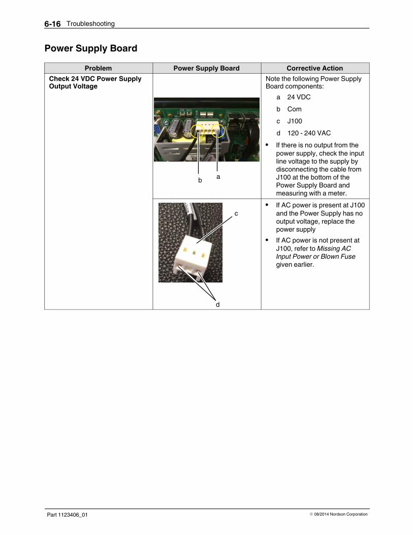
Troubleshooting6-16
Part 1123406_01 E 08/2014 Nordson Corporation
Power Supply BoardProblem Power Supply Board Corrective Action
Check 24 VDC Power SupplyOutput Voltage
ab
Note the following Power SupplyBoard components:
a 24 VDCb Comc J100d 120 - 240 VAC
S If there is no output from thepower supply, check the inputline voltage to the supply bydisconnecting the cable fromJ100 at the bottom of thePower Supply Board andmeasuring with a meter.
c
d
S If AC power is present at J100and the Power Supply has nooutput voltage, replace thepower supply
S If AC power is not present atJ100, refer toMissing ACInput Power or Blown Fusegiven earlier.
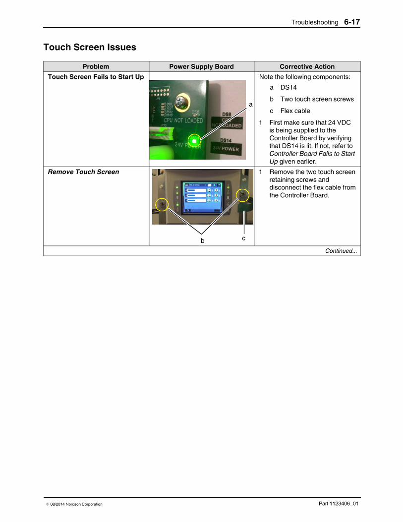
Troubleshooting 6-17
Part 1123406_01E 08/2014 Nordson Corporation
Touch Screen IssuesProblem Power Supply Board Corrective Action
Touch Screen Fails to Start Up
a
Note the following components:a DS14b Two touch screen screwsc Flex cable
1 First make sure that 24 VDCis being supplied to theController Board by verifyingthat DS14 is lit. If not, refer toController Board Fails to StartUp given earlier.
Remove Touch Screen
b c
1 Remove the two touch screenretaining screws anddisconnect the flex cable fromthe Controller Board.
Continued...
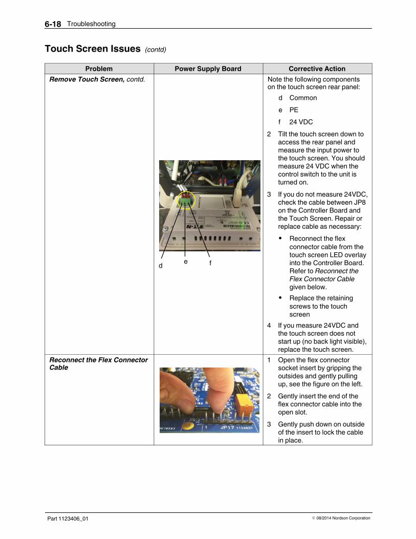
Troubleshooting6-18
Part 1123406_01 E 08/2014 Nordson Corporation
Touch Screen Issues (contd)
Problem Power Supply Board Corrective ActionRemove Touch Screen, contd.
d e f
Note the following componentson the touch screen rear panel:
d Commone PEf 24 VDC
2 Tilt the touch screen down toaccess the rear panel andmeasure the input power tothe touch screen. You shouldmeasure 24 VDC when thecontrol switch to the unit isturned on.
3 If you do not measure 24VDC,check the cable between JP8on the Controller Board andthe Touch Screen. Repair orreplace cable as necessary:S Reconnect the flex
connector cable from thetouch screen LED overlayinto the Controller Board.Refer to Reconnect theFlex Connector Cablegiven below.
S Replace the retainingscrews to the touchscreen
4 If you measure 24VDC andthe touch screen does notstart up (no back light visible),replace the touch screen.
Reconnect the Flex ConnectorCable
1 Open the flex connectorsocket insert by gripping theoutsides and gently pullingup, see the figure on the left.
2 Gently insert the end of theflex connector cable into theopen slot.
3 Gently push down on outsideof the insert to lock the cablein place.

Troubleshooting 6-19
Part 1123406_01E 08/2014 Nordson Corporation
Ethernet Network Communications IssuesProblem Power Supply Board Corrective Action
Touch Screen Fails toCommunicate
If the touch screen fails tocommunicate with the ControllerBoard for more than 30 seconds,the network communicationserror screen will appear.The most common cause of thiserror is a poorly connected orbroken Ethernet cable betweenthe Touch Screen and theController Board.
a bc
Note the following diagnosticsLEDs:
a Link LED (solid)b Data LED (flashing)c Ethernet cable
Use the diagnostic LEDs on theController Board and TouchScreen to check for propernetwork operation. Refer to thediagnostics LEDs shown in thefigure on the left.
Diagnosing Ethernet Problems
a b
c
Note the following components:a Data LED (flashing)b Link LED (solid)c Ethernet cable
When diagnosing Ethernetproblems, first make sure boththe Touch Screen and theController Board are poweredand running, refer to the previoustroubleshooting sections.If Ethernet LEDs show anabnormal condition, check tomake sure the ends of theEthernet cable are inserted fullyuntil an audible click is heard orfelt.
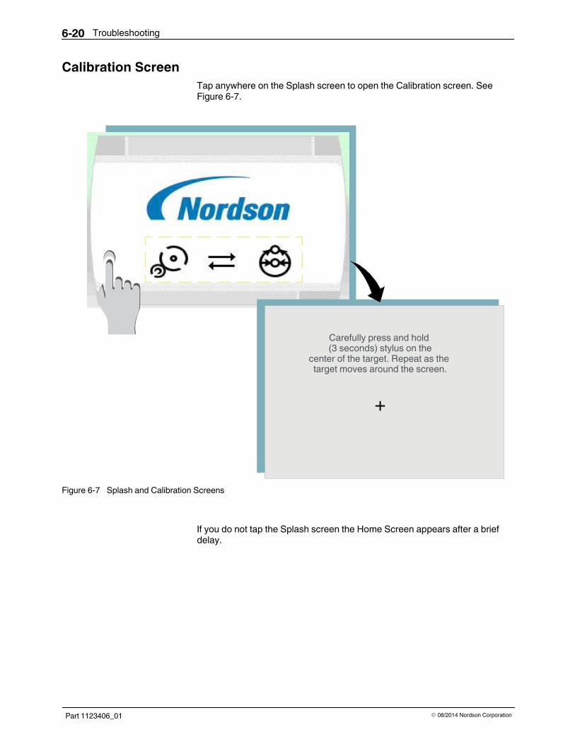
Troubleshooting6-20
Part 1123406_01 E 08/2014 Nordson Corporation
Calibration ScreenTap anywhere on the Splash screen to open the Calibration screen. SeeFigure 6-7.
Carefully press and hold(3 seconds) stylus on the
center of the target. Repeat as thetarget moves around the screen.
+
Figure 6-7 Splash and Calibration Screens
If you do not tap the Splash screen the Home Screen appears after a briefdelay.
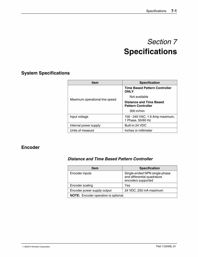
Specifications 7-1
Part 1123406_01E 08/2014 Nordson Corporation
Section 7Specifications
System SpecificationsItem Specification
Maximum operational line speed
Time Based Pattern ControllerONLY:
Not availableDistance and Time BasedPattern Controller
300 m/minInput voltage 100 - 240 VAC, 1.6 Amp maximum,
1 Phase, 50/60 HzInternal power supply Built-in 24 VDCUnits of measure Inches or millimeter
Encoder
Distance and Time Based Pattern ControllerItem Specification
Encoder inputs Single-ended NPN single-phaseand differential quadratureencoders supported
Encoder scaling YesEncoder power supply output 24 VDC, 250 mA maximumNOTE: Encoder operation is optional.

Specifications7-2
Part 1123406_01 E 08/2014 Nordson Corporation
InterfaceItem Specification
User interface 3.5 graphic touch screen LEDPassword lockout Enable or disable password lockout
featureLanguage support Text for upgrade and diagnostics
onlyOffline advanced settings Yes, it is available with the
Advanced Setting Utility.
Inputs/OutputsItem Specification
Digital input/output Six inputs (fixed patternselect/enable). Compatible with10 - 30 VDC sourcing outputs,3 mA maximumThree outputs (ready, alert, andfault/machine stop). 24 VDCsourcing output, 250 mA maximum
Remote enable Enable or disable remote enableRemote program recall Yes (optional)
EnclosureItem Specification
Enclosure type Plastic vertical/wall mountDimensions Width: 9.76 in. (248 mm)
Height: 9084 in. ( 250 mm)Depth: 5.66 in. (144 mm)
Enclosure IP rating IP44 (for mounting on the wall)IP54 (kit available, see Partssection)
Temperature range 0 - 45 _C (0 - 113 _F)50 _C (122 _F) with the fan option
CE approval YesUL approval YesROHSWEEE Yes
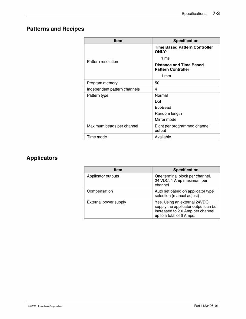
Specifications 7-3
Part 1123406_01E 08/2014 Nordson Corporation
Patterns and RecipesItem Specification
Pattern resolution
Time Based Pattern ControllerONLY:
1 msDistance and Time BasedPattern Controller
1 mmProgram memory 50Independent pattern channels 4Pattern type Normal
DotEcoBeadRandom lengthMirror mode
Maximum beads per channel Eight per programmed channeloutput
Time mode Available
ApplicatorsItem Specification
Applicator outputs One terminal block per channel.24 VDC, 1 Amp maximum perchannel
Compensation Auto set based on applicator typeselection (manual adjust)
External power supply Yes. Using an external 24VDCsupply the applicator output can beincreased to 2.0 Amp per channelup to a total of 6 Amps.

Specifications7-4
Part 1123406_01 E 08/2014 Nordson Corporation
TriggersItem Specification
Independent triggers FourProduct queuing TenFalse trigger block YesStuck photocell YesSignals accepted NPN or PNP.
24 VDC line driver with jumpersetting change, 3 mA current drawmaximum
Trigger power supply output 24 VDC, 250 mA maximum pertrigger
Pressure Run-upItem Specification
Run-up Outputs OneNumber of points on curve TwoOutput type 4 - 20 mA and 0 - 10V
Run-up loads 4 - 20 mA: 600 Ohms0 - 10V: 1000 Ohms
Run-up power supply output 24 VDC, 250 mA maximum

Specifications 7-5
Part 1123406_01E 08/2014 Nordson Corporation
DiagnosticsItem Specification
Messages Detailed textDiagnostic log size Twenty five (25)Troubleshooting assistance Troubleshooting tips included
Software LicenseThe three pattern controller configurations (time based, distance based, orpressure run-up) can be upgraded by ordering additional licenses(s). Thesesoftware licenses can be ordered by specific part numbers. Refer to Parts forthe software license part numbers.
The add-on features are:- Encoder- Pressure/Run-up- Remote recall

Specifications7-6
Part 1123406_01 E 08/2014 Nordson Corporation
System Schematic
Figure 7-8 System Schematic
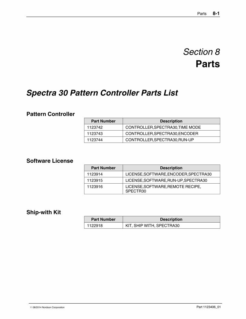
Parts 8-1
Part 1123406_01E 08/2014 Nordson Corporation
Section 8Parts
Spectra 30 Pattern Controller Parts List
Pattern ControllerPart Number Description
1123742 CONTROLLER,SPECTRA30,TIME MODE1123743 CONTROLLER,SPECTRA30,ENCODER1123744 CONTROLLER,SPECTRA30,RUN-UP
Software LicensePart Number Description
1123914 LICENSE,SOFTWARE,ENCODER,SPECTRA301123915 LICENSE,SOFTWARE,RUN-UP,SPECTRA301123916 LICENSE,SOFTWARE,REMOTE RECIPE,
SPECTR30
Ship-with KitPart Number Description
1122918 KIT, SHIP WITH, SPECTRA30

Parts8-2
Part 1123406_01 E 08/2014 Nordson Corporation
Service KitsSee Figure 8-9 for the location of the main kit components.
Item Part Number Description1 1123815 KIT,FAN,SPECTRA2 1123816 KIT,PWRSUP,SPECTRA3 1123817 KIT,HMI,SPECTRA4 1123818 KIT,MAIN BOARD,SPECTRA
Not Shown 1123819 KIT,IP54,SPECTRA
1
2
34
Figure 8-9 Location of the kit components

Parts 8-3
Part 1123406_01E 08/2014 Nordson Corporation
Add-on Features Parts ListComponent Part Description Quantity
Encoder 772050 SPEEDSENS,ENCDR,500PULSE,10MM 1772051 SPEEDSENS,ENCDR500PULSE,3/8IN 1772052 CABLASSY,ENCDR,10POS,CIR,30FT 1772053 CABLASSY,ENCDR,10POS,CIR,
WATERWASH,30FT1
296144 WHEEL, FRICTION, .50 METER, 3/8 INCH DIA 1Trigger (Sensor) 131474 SENSOR, RETROREFLECTIVE MODE 1
131475 SENSOR, RETROREFLECTIVE,POLAR 1131476 SENSOR,DIFFUSE MODE 1
Transducer (forRun-Up Control)
154890 TRANSDUCER ASSY,EXT.RANGE.KIT 11123923 KIT,RUN UP, 0-10VDC,120PSI, GEAR/PISTON 11123960 KIT,RUN UP, 4-20mA,120PSI, GEAR/PISTON 1

Parts8-4
Part 1123406_01 E 08/2014 Nordson Corporation