spectral efficiency of massive mimo systems with d2d underlay
TRANSCRIPT
© Robert W. Heath Jr. (2015)
Spectral Efficiency of Massive MIMO Systems with D2D Underlay
Xingqin Lin*, Robert W. Heath Jr.#, and Jeffrey G. Andrews# * Radio Access Technologies, Ericsson Research, San Jose, CA, USA # Wireless Networking and Communications Group, Department of Electrical and Computer Engineering, The University of Texas at Austin IEEE ICC 2015, London, UK
© Robert W. Heath Jr. (2015)
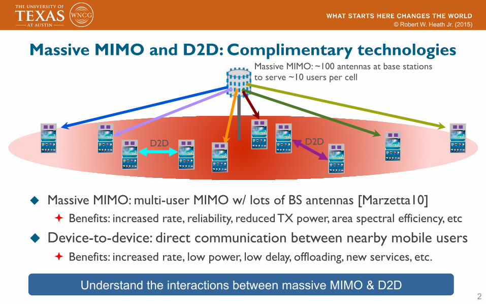
Massive MIMO and D2D: Complimentary technologies
u Massive MIMO: multi-user MIMO w/ lots of BS antennas [Marzetta10] ª Benefits: increased rate, reliability, reduced TX power, area spectral efficiency, etc
u Device-to-device: direct communication between nearby mobile users ª Benefits: increased rate, low power, low delay, offloading, new services, etc.
2
Massive MIMO: ~100 antennas at base stationsto serve ~10 users per cell
D2D D2D
Understand the interactions between massive MIMO & D2D

© Robert W. Heath Jr. (2015)
Related work u Stochastic geometry analysis for cellular [Andrews11, Dhilon12, Heath13] u Massive MIMO
ª Networks of finite size: [Marzetta10, Hul12, Ngo13, Hoydis13, Truong13] ª Networks w/ spatially distributed nodes: [Madhul13, Bai14, Liang15]
u D2D ª Qualcomm FlashLinQ [Wu13] ª Much work on single-antenna [Lin14], some on multi-antenna [Janis09, Min11] ª Several analyses related to spatially distributed nodes
u Massive MIMO + D2D [Yin14] ª Use D2D to enable local CSI exchange in a FDD massive MIMO system
3 No related work on massive MIMO + D2D + stochastic geometry

© Robert W. Heath Jr. (2015)
4
Questions answered in our work
Assume perfect CSI (imperfect CSI is here* )
Asymptotic and non-asymptotic results in large # of antennas
How does D2D impact the spectral and energy efficiency of massive MIMO?
How does massive MIMO impact D2D spectral efficiency?
* X. Lin, R. W. Heath Jr., and J. G. Andrews, ‘‘The interplay between massive MIMO and underlaid D2D networking,’’ IEEE Transactions on Wireless Communications, to appear.

© Robert W. Heath Jr. (2015)
System model
u D2D underlaid multi-cell cellular network (shares uplink) ª Each cell has K randomly distributed uplink cellular UEs ª PPP distributed D2D TXs with density λ ª Each D2D TX has a D2D RX located at distance D away from the TX
u SIMO scenario ª TXs (either cellular or D2D) use a single antenna ª Each BS has M receive antennas ª Each D2D RX has N receive antennas
5
g(d)ii
h(d)i
h(c)0k
g(d)ir
g(c)ik
M Rx antennas at the BS 0 Single cell

© Robert W. Heath Jr. (2015)
cellular system only consists of single cell, D2D pairs aredistributed throughout the plane and those D2D pairs locatedoutside the cell contribute to out-of-cell D2D interference.
In this system, all the transmitters use the same time-frequency resource block, leading to cochannel interference.We assume that cellular and D2D UEs transmit at constantpowers Pc and Pd respectively.
B. Baseband Channel Models
The M ⇥1 dimensional baseband received signal at the BSis
y(c)=
X
k2K
pPckx(c)
k
k�↵c2 h(c)
k
u
(c)k
+
X
i2�
pPdkx(d)
i
k�↵c2 h(d)
i
u
(d)i
+ v(c), (1)
where x
(c)k
denotes the position of cellular transmitter k, ↵c >
2 denotes the pathloss exponent of UE-BS links, h(c)k
2 CM⇥1
is the vector channel from cellular transmitter k to the BS,u
(c)k
denotes the zero-mean unit-variance transmit symbol ofcellular transmitter k, x(d)
i
,h(d)i
2 CM⇥1 and u
(d)i
are similarlydefined for D2D transmitter i, and v(c) 2 CM⇥1 is complexGaussian noise with covariance N0IM with I
M
denoting theM dimensional identity matrix.
Similarly, the N ⇥ 1 dimensional baseband received signalat the D2D receiver r is
y(d)r
=
X
k2K
pPc(d
(c)rk
)
�↵d2 g(c)
rk
u
(c)k
+
X
i2�
pPd(d
(d)ri
)
�↵d2 g(d)
ri
u
(d)i
+ v(d)r
, (2)
where d
(s)rk
= kx(s)k
� z
(d)r
k with s 2 {c, d} and z
(d)r
denotingthe position of D2D receiver r, ↵d > 2 denotes the pathlossexponent of UE-UE links, g(c)
rk
,g(d)ri
2 CN⇥1 are the vectorchannels from the cellular transmitter k to the D2D receiverr and from the D2D transmitter i to the D2D receiver r
respectively, and v(d)r
2 CN⇥1 is complex Gaussian noise withcovariance N0IN .
Note that we have used different pathloss exponents ↵c and↵d for UE-BS and UE-UE links (cf. (1) and (2)) due to theirdifferent propagation characteristics. Specifically, the antennaheight of a macro BS is tens of meters, while the typicalantenna height at a UE is under 2 m. As a result, both terminalsof a UE-UE link are low and see similar near street scatteringenvironment, which is different from the radio environmentaround a macro BS [2].
In this paper, we assume Gaussian signaling, i.e., {u(s)k
}, s 2{c, d}, are i.i.d. zero-mean unit-variance complex GaussianCN (0, 1), and that all the vector channels, h(s)
k
and g(s)rk
, s 2{c, d}, have i.i.d. CN (0, 1) elements, independent across trans-mitters. It follows that the favorable propagation condition [3]desired in massive MIMO systems holds in our model:
1
M
h(s)⇤r
h(s0)`
a.s.��!⇢
1 if s = s
0 and r = `;
0 otherwise,
where a.s.��! denotes the almost sure convergence, as M ! 1.
C. Receive Filters
Denote by w(c)k
the filter used by the BS for receiving thesignal of the k-th cellular transmitter, i.e., the BS detects thesymbol u(c)
k
based on w(c)⇤k
y(c). Similarly, the D2D receiverr detects the symbol u
(d)r
based on w(d)⇤r
y(d)r
, where w(d)r
denotes the filter used by the D2D receiver r. The performanceof the D2D underlaid massive MIMO system depends on thereceive filters. In general, either the receive filters can bedesigned to boost desired signal power or they can be usedto cancel undesired interference. In this paper, we focus on aparticular type of linear filters: the PZF receiver, which uses asubset of the degrees of freedom for boosting received signalpower and the remainder for interference cancellation.
The BS uses mc and md degrees of freedom to cancel theinterference from the nearest mc cellular interferers and mdD2D interferers. The PZF filter w(c)
k
is the projection of thechannel vector h(c)
k
onto the subspace orthogonal to the onespanned by the column vectors of canceled interferers. Forease of reference, we denote by K(c)
k
the set of uncanceled
cellular interferers and �
(c)k
the set of uncanceled D2D in-terferers when detecting the symbol u(c)
k
of the k-th cellulartransmitter.
Similarly, each D2D receiver uses nc and nd degrees offreedom to cancel the interference from the nearest nc cellularinterferers and nd D2D interferers. The PZF filter w(d)
r
atthe D2D receiver r is the projection of the channel vectorg(d)rr
onto the subspace orthogonal to the one spanned by thecolumn vectors of canceled interferers. For ease of reference,we denote by K(d)
r
the set of uncanceled cellular interferersand �
(d)r
the set of uncanceled D2D interferers at the D2Dreceiver r.
III. CELLULAR SPECTRAL EFFICIENCY
A. Asymptotic Cellular Spectral Efficiency
For the k-th cellular UE, the post-processing SINR with thePZF filter w(c)
k
is
SINR(c)k
=
S
(c)k
I
(c!c)k
+ I
(d!c)k
+ kw(c)k
k2N0
, (3)
where S
(c)k
= Pckx(c)k
k�↵ckw(c)⇤k
h(c)k
k2 denotes the desiredsignal power of cellular UE k, I(c!c)
k
and I
(d!c)k
respectivelydenote the cochannel cellular and D2D interference powersexperienced by cellular UE k and are given by
I
(c!c)k
=
X
`2K(c)k
Pckx(c)`
k�↵c |w(c)⇤k
h(c)`
|2
I
(d!c)k
=
X
i2�(c)k
Pdkx(d)i
k�↵c |w(c)⇤k
h(d)i
|2. (4)
The spectral efficiency of the k-th cellular UE is defined as
R
(c)k
= Ehlog(1 + SINR(c)
k
)
i, (5)
5962
Baseband channel model and receive processing
u The total received signal at the central BS (similar model for D2D users) u Partial zero-forcing (PZF) receivers
ª BS cancels nearest mc nearest cellular and md nearest D2D interferers ª D2D receiver cancels nearest nc nearest cellular and nd nearest D2D interferers
6
Cellular signals D2D signals Noise
TX power
Position Fast fading
Data symbol
Pathloss exponent

© Robert W. Heath Jr. (2015)
Performance evaluation for cellular users u Average spectral efficiency is the main performance metric
7
R(c)k = E
"log
1 +
S(c)k
I(c!c)k + I(d!c)
k +N0
!#cell
user k
Compute rate assuming perfect CSI
cellular system only consists of single cell, D2D pairs aredistributed throughout the plane and those D2D pairs locatedoutside the cell contribute to out-of-cell D2D interference.
In this system, all the transmitters use the same time-frequency resource block, leading to cochannel interference.We assume that cellular and D2D UEs transmit at constantpowers Pc and Pd respectively.
B. Baseband Channel Models
The M ⇥1 dimensional baseband received signal at the BSis
y(c)=
X
k2K
pPckx(c)
k
k�↵c2 h(c)
k
u
(c)k
+
X
i2�
pPdkx(d)
i
k�↵c2 h(d)
i
u
(d)i
+ v(c), (1)
where x
(c)k
denotes the position of cellular transmitter k, ↵c >
2 denotes the pathloss exponent of UE-BS links, h(c)k
2 CM⇥1
is the vector channel from cellular transmitter k to the BS,u
(c)k
denotes the zero-mean unit-variance transmit symbol ofcellular transmitter k, x(d)
i
,h(d)i
2 CM⇥1 and u
(d)i
are similarlydefined for D2D transmitter i, and v(c) 2 CM⇥1 is complexGaussian noise with covariance N0IM with I
M
denoting theM dimensional identity matrix.
Similarly, the N ⇥ 1 dimensional baseband received signalat the D2D receiver r is
y(d)r
=
X
k2K
pPc(d
(c)rk
)
�↵d2 g(c)
rk
u
(c)k
+
X
i2�
pPd(d
(d)ri
)
�↵d2 g(d)
ri
u
(d)i
+ v(d)r
, (2)
where d
(s)rk
= kx(s)k
� z
(d)r
k with s 2 {c, d} and z
(d)r
denotingthe position of D2D receiver r, ↵d > 2 denotes the pathlossexponent of UE-UE links, g(c)
rk
,g(d)ri
2 CN⇥1 are the vectorchannels from the cellular transmitter k to the D2D receiverr and from the D2D transmitter i to the D2D receiver r
respectively, and v(d)r
2 CN⇥1 is complex Gaussian noise withcovariance N0IN .
Note that we have used different pathloss exponents ↵c and↵d for UE-BS and UE-UE links (cf. (1) and (2)) due to theirdifferent propagation characteristics. Specifically, the antennaheight of a macro BS is tens of meters, while the typicalantenna height at a UE is under 2 m. As a result, both terminalsof a UE-UE link are low and see similar near street scatteringenvironment, which is different from the radio environmentaround a macro BS [2].
In this paper, we assume Gaussian signaling, i.e., {u(s)k
}, s 2{c, d}, are i.i.d. zero-mean unit-variance complex GaussianCN (0, 1), and that all the vector channels, h(s)
k
and g(s)rk
, s 2{c, d}, have i.i.d. CN (0, 1) elements, independent across trans-mitters. It follows that the favorable propagation condition [3]desired in massive MIMO systems holds in our model:
1
M
h(s)⇤r
h(s0)`
a.s.��!⇢
1 if s = s
0 and r = `;
0 otherwise,
where a.s.��! denotes the almost sure convergence, as M ! 1.
C. Receive Filters
Denote by w(c)k
the filter used by the BS for receiving thesignal of the k-th cellular transmitter, i.e., the BS detects thesymbol u(c)
k
based on w(c)⇤k
y(c). Similarly, the D2D receiverr detects the symbol u
(d)r
based on w(d)⇤r
y(d)r
, where w(d)r
denotes the filter used by the D2D receiver r. The performanceof the D2D underlaid massive MIMO system depends on thereceive filters. In general, either the receive filters can bedesigned to boost desired signal power or they can be usedto cancel undesired interference. In this paper, we focus on aparticular type of linear filters: the PZF receiver, which uses asubset of the degrees of freedom for boosting received signalpower and the remainder for interference cancellation.
The BS uses mc and md degrees of freedom to cancel theinterference from the nearest mc cellular interferers and mdD2D interferers. The PZF filter w(c)
k
is the projection of thechannel vector h(c)
k
onto the subspace orthogonal to the onespanned by the column vectors of canceled interferers. Forease of reference, we denote by K(c)
k
the set of uncanceled
cellular interferers and �
(c)k
the set of uncanceled D2D in-terferers when detecting the symbol u(c)
k
of the k-th cellulartransmitter.
Similarly, each D2D receiver uses nc and nd degrees offreedom to cancel the interference from the nearest nc cellularinterferers and nd D2D interferers. The PZF filter w(d)
r
atthe D2D receiver r is the projection of the channel vectorg(d)rr
onto the subspace orthogonal to the one spanned by thecolumn vectors of canceled interferers. For ease of reference,we denote by K(d)
r
the set of uncanceled cellular interferersand �
(d)r
the set of uncanceled D2D interferers at the D2Dreceiver r.
III. CELLULAR SPECTRAL EFFICIENCY
A. Asymptotic Cellular Spectral Efficiency
For the k-th cellular UE, the post-processing SINR with thePZF filter w(c)
k
is
SINR(c)k
=
S
(c)k
I
(c!c)k
+ I
(d!c)k
+ kw(c)k
k2N0
, (3)
where S
(c)k
= Pckx(c)k
k�↵ckw(c)⇤k
h(c)k
k2 denotes the desiredsignal power of cellular UE k, I(c!c)
k
and I
(d!c)k
respectivelydenote the cochannel cellular and D2D interference powersexperienced by cellular UE k and are given by
I
(c!c)k
=
X
`2K(c)k
Pckx(c)`
k�↵c |w(c)⇤k
h(c)`
|2
I
(d!c)k
=
X
i2�(c)k
Pdkx(d)i
k�↵c |w(c)⇤k
h(d)i
|2. (4)
The spectral efficiency of the k-th cellular UE is defined as
R
(c)k
= Ehlog(1 + SINR(c)
k
)
i, (5)
5962
Uncancelled cellular users (come from finite set)
Uncancelled D2D users (distributed as a PPP)
cellular system only consists of single cell, D2D pairs aredistributed throughout the plane and those D2D pairs locatedoutside the cell contribute to out-of-cell D2D interference.
In this system, all the transmitters use the same time-frequency resource block, leading to cochannel interference.We assume that cellular and D2D UEs transmit at constantpowers Pc and Pd respectively.
B. Baseband Channel Models
The M ⇥1 dimensional baseband received signal at the BSis
y(c)=
X
k2K
pPckx(c)
k
k�↵c2 h(c)
k
u
(c)k
+
X
i2�
pPdkx(d)
i
k�↵c2 h(d)
i
u
(d)i
+ v(c), (1)
where x
(c)k
denotes the position of cellular transmitter k, ↵c >
2 denotes the pathloss exponent of UE-BS links, h(c)k
2 CM⇥1
is the vector channel from cellular transmitter k to the BS,u
(c)k
denotes the zero-mean unit-variance transmit symbol ofcellular transmitter k, x(d)
i
,h(d)i
2 CM⇥1 and u
(d)i
are similarlydefined for D2D transmitter i, and v(c) 2 CM⇥1 is complexGaussian noise with covariance N0IM with I
M
denoting theM dimensional identity matrix.
Similarly, the N ⇥ 1 dimensional baseband received signalat the D2D receiver r is
y(d)r
=
X
k2K
pPc(d
(c)rk
)
�↵d2 g(c)
rk
u
(c)k
+
X
i2�
pPd(d
(d)ri
)
�↵d2 g(d)
ri
u
(d)i
+ v(d)r
, (2)
where d
(s)rk
= kx(s)k
� z
(d)r
k with s 2 {c, d} and z
(d)r
denotingthe position of D2D receiver r, ↵d > 2 denotes the pathlossexponent of UE-UE links, g(c)
rk
,g(d)ri
2 CN⇥1 are the vectorchannels from the cellular transmitter k to the D2D receiverr and from the D2D transmitter i to the D2D receiver r
respectively, and v(d)r
2 CN⇥1 is complex Gaussian noise withcovariance N0IN .
Note that we have used different pathloss exponents ↵c and↵d for UE-BS and UE-UE links (cf. (1) and (2)) due to theirdifferent propagation characteristics. Specifically, the antennaheight of a macro BS is tens of meters, while the typicalantenna height at a UE is under 2 m. As a result, both terminalsof a UE-UE link are low and see similar near street scatteringenvironment, which is different from the radio environmentaround a macro BS [2].
In this paper, we assume Gaussian signaling, i.e., {u(s)k
}, s 2{c, d}, are i.i.d. zero-mean unit-variance complex GaussianCN (0, 1), and that all the vector channels, h(s)
k
and g(s)rk
, s 2{c, d}, have i.i.d. CN (0, 1) elements, independent across trans-mitters. It follows that the favorable propagation condition [3]desired in massive MIMO systems holds in our model:
1
M
h(s)⇤r
h(s0)`
a.s.��!⇢
1 if s = s
0 and r = `;
0 otherwise,
where a.s.��! denotes the almost sure convergence, as M ! 1.
C. Receive Filters
Denote by w(c)k
the filter used by the BS for receiving thesignal of the k-th cellular transmitter, i.e., the BS detects thesymbol u(c)
k
based on w(c)⇤k
y(c). Similarly, the D2D receiverr detects the symbol u
(d)r
based on w(d)⇤r
y(d)r
, where w(d)r
denotes the filter used by the D2D receiver r. The performanceof the D2D underlaid massive MIMO system depends on thereceive filters. In general, either the receive filters can bedesigned to boost desired signal power or they can be usedto cancel undesired interference. In this paper, we focus on aparticular type of linear filters: the PZF receiver, which uses asubset of the degrees of freedom for boosting received signalpower and the remainder for interference cancellation.
The BS uses mc and md degrees of freedom to cancel theinterference from the nearest mc cellular interferers and mdD2D interferers. The PZF filter w(c)
k
is the projection of thechannel vector h(c)
k
onto the subspace orthogonal to the onespanned by the column vectors of canceled interferers. Forease of reference, we denote by K(c)
k
the set of uncanceled
cellular interferers and �
(c)k
the set of uncanceled D2D in-terferers when detecting the symbol u(c)
k
of the k-th cellulartransmitter.
Similarly, each D2D receiver uses nc and nd degrees offreedom to cancel the interference from the nearest nc cellularinterferers and nd D2D interferers. The PZF filter w(d)
r
atthe D2D receiver r is the projection of the channel vectorg(d)rr
onto the subspace orthogonal to the one spanned by thecolumn vectors of canceled interferers. For ease of reference,we denote by K(d)
r
the set of uncanceled cellular interferersand �
(d)r
the set of uncanceled D2D interferers at the D2Dreceiver r.
III. CELLULAR SPECTRAL EFFICIENCY
A. Asymptotic Cellular Spectral Efficiency
For the k-th cellular UE, the post-processing SINR with thePZF filter w(c)
k
is
SINR(c)k
=
S
(c)k
I
(c!c)k
+ I
(d!c)k
+ kw(c)k
k2N0
, (3)
where S
(c)k
= Pckx(c)k
k�↵ckw(c)⇤k
h(c)k
k2 denotes the desiredsignal power of cellular UE k, I(c!c)
k
and I
(d!c)k
respectivelydenote the cochannel cellular and D2D interference powersexperienced by cellular UE k and are given by
I
(c!c)k
=
X
`2K(c)k
Pckx(c)`
k�↵c |w(c)⇤k
h(c)`
|2
I
(d!c)k
=
X
i2�(c)k
Pdkx(d)i
k�↵c |w(c)⇤k
h(d)i
|2. (4)
The spectral efficiency of the k-th cellular UE is defined as
R
(c)k
= Ehlog(1 + SINR(c)
k
)
i, (5)
5962

© Robert W. Heath Jr. (2015)
Cellular user large antenna regime u Spectral efficiency goes to infinity (asymptotic orthogonality & perfect CSI) u If Pc=Θ(1/Μ), a limiting finite cellular spectral efficiency is achieved
8 8
R(c)k ! log(1 + SNR
(c)0k )
lim
M!1R(c)
k � log
1 +
SNR
(c)0k
⇢(md,↵c) + 1
!
Mean D2D canceled interf.
R(c)k ! log(1 + SNR
(c)0k )
Like having no D2D interference
without D2D with D2D and a fixed md
scaling up md with Θ(log(Μ))
No loss of spectral efficiency and power saving due to the D2D underlay if md scales appropriately
where the expectation is taken with respect to the fast fadingand the random locations of D2D transmitters.Proposition 1. With perfect CSI, as M ! 1, the desired
signal power S
(c)k
when normalized by M
2converges to
lim
M!1
1
M
2S
(c)k
a.s.��! P
c
kx(c)k
k�↵
c
, (6)
and the cellular interference power I
(c!c)k
, the D2D interfer-
ence power I
(d!c)k
, and the noise power kw(c)k
k2N0 when
normalized by M
2converge as follows.
lim
M!1
1
M
2I
(c!c)k
a.s.��! 0, lim
M!1
1
M
2I
(d!c)k
p.�! 0
lim
M!1
1
M
2kw(c)
k
k2N0a.s.��! 0, (7)
where
p.�! denotes the convergence in probability.
Proof: (Sketch) We show that a PZF receiver with mc =
md = 0, i.e., a maximum ratio combining (MRC) receiver,at the BS suffices. With mc = md = 0, the PZF receiverw(c)
k
= h(c)k
. By the law of large numbers, 1M
kh(c)k
k2 a.s.��! 1,1M
h(c)⇤k
h(c)`
a.s.��! 0, ` 6= k. It follows that
1
M
2Pckx(c)
k
k�↵ckh(c)k
k4 a.s.��! Pckx(c)k
k�↵c
1
M
2N0kh(c)
k
k2 a.s.��! 0. (8)
Further, interchanging the order of the limit and the finite sum,
lim
M!1
1
M
2
X
`2K:` 6=k
Pckx(c)`
k�↵c |h(c)⇤k
h(c)`
|2
=
X
`2K:` 6=k
Pckx(c)`
k�↵c
✓lim
M!1
1
M
2|h(c)⇤
k
h(c)`
|2◆
a.s.��! 0.
As for lim
M!11
M
2 I(d!c)k
, we cannot directly interchangethe order of the limit and the infinite sum to conclude thatit converges to 0 almost surely. Instead, we can prove itsconvergence in probability, i.e., for any ✏ > 0,
lim
M!1P
1
M
2
X
i2�
Pdkx(d)i
k�↵c |h(c)⇤k
h(d)i
|2 < ✏
!= 1. (9)
The technical detail can be found in [11].Prop. 1 shows that with perfect CSI, as M ! 1, the post-
processing SINR(c)k
increases unboundedly with probability 1
(as almost sure convergence implies convergence in probabil-ity). More specifically, a deterministic received power of thedesired signal from cellular UE k can be achieved and theeffects of noise, fast fading, and the interfering signals fromthe other K�1 cellular UEs and the infinite D2D transmittersvanish completely. Therefore, Prop. 1 validates the intuitionthat with perfect CSI, D2D-to-cellular interference can bemade arbitrarily small with a large enough antenna array atthe BS. Perhaps the most surprising result from Prop. 1 isthat the D2D-to-cellular interference can be completely nulledout (with probability 1) even though the number of the PPPdistributed D2D interferers is infinite and the mean of the
aggregate D2D interference is infinite. Further, the proof ofProp. 1 shows that a simple MRC filter with mc = md = 0
suffices. Note that a similar convergence as in Prop. 1 has beenshown in a non-D2D setup [14].
Though Prop. 1 shows that arbitrarily large received SINRcan be achieved with massive MIMO, this in practice willultimately fail since the received power cannot be larger thanthe transmit power. The large array gains, however, may betranslated into power savings for cellular UEs: with a givenSNR target we can lower the transmit powers of cellular UEsand thus improve their energy efficiency, as shown in thefollowing proposition.
Proposition 2. With perfect CSI, fixed PZF parameters
(m
c
,m
d
), and scaled cellular transmit power P
c
/M , as M !1, the spectral efficiency R
(c)k
of cellular UE k converges to
R
(c)k
! E�,⌘
2
4log
0
@1 +
SNR
(c)kP
i2�(c)k
P
d
N0kx(d)
i
k�↵
c
⌘
i
+ 1
1
A
3
5,
(10)
where SNR
(c)k
= P
c
kx(c)k
k�↵
c
/N0, {⌘i
} are i.i.d. random
variables distributed as ⌘
i
⇠ Exp(1). Further, if m
d
+ 1 >
↵
c
2 ,
lim
M!1R
(c)k
� log
1 +
SNR
(c)k
⇢(m
d
,↵
c
) + 1
!, (11)
where
⇢(m,↵) =
2(⇡�)
↵2P
d
�(m+ 1� ↵
2 )
(↵� 2)N0�(m)
, (12)
where the Gamma function �(x) =
R10 t
x�1e
�t
dt.
Proof: (Sketch) When the transmit powers of cellular UEsscale as Pc/M , as in the proof of Prop. 1, we can show thatlim
M!11M
S
(c)k
a.s.��! Pckx(c)k
k�↵c , limM!1
1M
I
(c!c)k
a.s.��!0, lim
M!11M
kw(c)k
k2N0a.s.��! N0. We can further show
that 1M
I
(d!c)k
d.�!P
i2�(c)k
Pdkx(d)i
k�↵c⌘
i
, where d.�! denotesthe convergence in distribution, by proving that the Laplacetransform of the former converges to that of the latter. Thelower bound (11) is due to Jensen’s inequality:
lim
M!1R
(c)k
� log
0
@1 +
Pckx(c)k
k�↵c
E[P
i2�(c)k
Pdkx(d)i
k�↵c⌘
i
] +N0
1
A,
and E[P
i2�(c)k
Pdkx(d)i
k�↵c⌘
i
] = ⇢(md,↵c).Note that in Prop. 2, if the underlaid D2D transmitters did
not exist, the spectral efficiency R
(c)k
of cellular UE k wouldconverge to log
⇣1 + SNR(c)
k
⌘, the maximum achievable spec-
tral efficiency of a point-to-point SISO (single-input single-output) Gaussian channel. It is as if massive MIMO couldsimultaneously support K interference-free SISO links whilereducing the power of each cellular UE by 10 log10 M dB.This result is consistent with Prop. 1 in [15] without D2Dunderlay.
With D2D underlay, the asymptotic result (10) shows that
5963
© Robert W. Heath Jr. (2015)
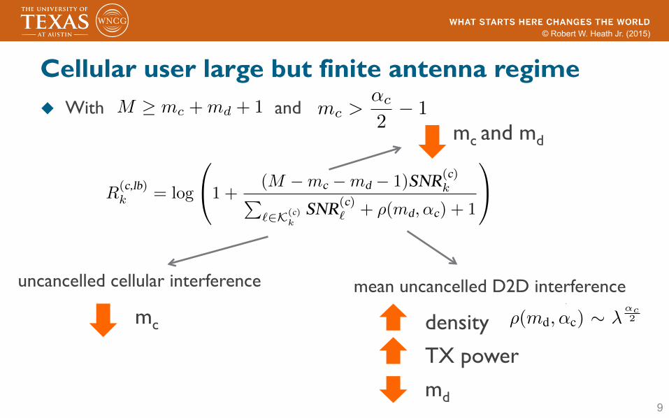
Cellular user large but finite antenna regime u With and
9
M � mc +md + 1 mc >↵c
2� 1
there is a loss in cellular spectral efficiency due to theuncanceled interfering signals from the D2D transmitters in�
(c)k
, i.e., D2D transmitters in � except the nearest md oneswhose signals are canceled by the PZF filter. Though it ispossible to derive an exact analytical expression (involvingintegrals) for (10), we give a more intuitive lower bound(11), which succinctly characterizes the loss due to the D2Dunderlay through a single term ⇢(md,↵c). Several remarks arein order.
Remark 1. The term ⇢(md,↵c) corresponding to the un-canceled D2D interference increases with Pd and � and de-creases with md, agreeing with intuition: larger transmit poweror larger density of D2D interferers or smaller number ofcanceled D2D interferers leads to higher D2D-to-cellular inter-ference, thus lowering the cellular spectral efficiency. Further,⇢(md,↵c) ⇠ �
↵c2 because a linear increase in � implies that
the distances of the PPP distributed D2D transmitters to theBS decrease as �
12 and thus the D2D-to-cellular interference
power increases as �
↵c2 .
Remark 2. Note that the lower bound (11) is meaningfulonly if md +1 >
↵c2 . As md ! ↵c
2 � 1, �(md +1� ↵c2 ) ! 1
and thus ⇢(md,↵c) ! 1. In fact, we can show that if thiscondition is violated, the expected interference from the (md+
1)-th nearest D2D transmitter to the BS would be infinite.Remark 3. It can be shown that as md becomes large,
�(md) ⇠ (md � 1)
↵c2�(md � ↵c
2 ) and thus
�(md + 1� ↵c2 )
�(md)⇠
md � ↵c2
(md � 1)
↵c2
. (13)
Therefore, ⇢(md,↵c) decreases at a polynomial rate ↵c2 � 1
as md increases. To completely null out the D2D-to-cellularinterference, we need only appropriately increase md as M
grows. The growth rate of md can be arbitrarily slow. In partic-ular, if M increases linearly, asymptotically md = ⇥(logM)
degrees of freedom are sufficient to null out the D2D-to-cellular interference caused by the infinite D2D transmitters.This leaves the BS ⇥(M � logM) = ⇥(M) degrees offreedom to boost the signal power. Therefore, the transmitpower of each cellular UE can still be scaled down as ⇥(1/M).In other words, there is no loss of spectral efficiency andpower saving due to the D2D underlay as long as md scalesas ⇥(logM).
B. Non-asymptotic Cellular Spectral Efficiency
Next we analyze the cellular spectral efficiency in the non-asymptotic regime to generate more insights into the impact ofthe various system parameters. To this end, we derive a lowerbound for R(c)
k
in the following proposition.Proposition 3. With perfect CSI, M � m
c
+m
d
+1 and m
d
>
↵
c
2 � 1, the spectral efficiency R
(c)k
of cellular UE k is lower
bounded by
R
(c,lb)k
= log
0
@1 +
(M �m
c
�m
d
� 1)SNR
(c)kP
`2K(c)k
SNR
(c)`
+ ⇢(m
d
,↵
c
) + 1
1
A,
(14)
where ⇢(m,↵) is defined in (12).
Proof: (Sketch) Using the convexity of the functionlog(1 +
1x
) and applying Jensen’s inequality, R(c)k
is greaterthan or equal to
log
0
@1 +
E"
1
S
(c)k
#· (E[I(c!c)
k
] + E[I(d!c)k
] +N0)
!�11
A.
The lower bound (14) is obtained by calculating E
1
S
(c)k
�,
E[I(c!c)k
], and E[I(d!c)k
] respectively and then plugging theminto the above inequality.
Note that the first term in the denominator of (14) corre-sponds to the uncanceled cellular interference; it decreases asmc increases. Similarly, the second term in the denominatorof (14) corresponds to the uncanceled D2D interference; itdecreases as md increases. In contrast, the numerator of (14)corresponds to the desired signal power; it decreases as mcand/or md increase. The lower bound (14) demonstrates thevarious tradeoffs when choosing the PZF parameters mc andmd. Note that such tradeoffs disappear in the asymptoticregime (cf. Prop. 2). If the PZF parameter mc = K�1, then allthe cochannel cellular interference will be nulled out, leadingto the following specialized lower bound.
R
(c,lb)k
= log
1 +
(M �K �md)SNR(c)k
⇢(md,↵c) + 1
!. (15)
We point out that the received signal power gain is onlyproportional to M � mc � md � 1 in the lower bound (14).One might think the power gain should be proportional toM � mc � md, the number of degrees of freedom left forpower boosting after using mc + md degrees of freedom forinterference cancellation. The fallacy of the above argumentis that it ignores the effect of fading, which makes a powergain proportional to M �mc �md unachievable.
IV. D2D SPECTRAL EFFICIENCY
For D2D receiver r, the post-processing SINR with PZFfilter is
SINR(d)r
=
S
(d)r
I
(c!d)r
+ I
(d!d)r
+ kw(d)r
k2N0
, (16)
where S
(d)r
= Pdd�↵dkw(d)⇤
r
g(d)rr
k2 denotes the desired signalpower of D2D Tx-Rx pair r, I(c!d)
r
and I
(d!d)r
respectivelydenote the cochannel cellular and D2D interference powersexperienced by D2D receiver r and are given by
I
(c!d)r
=
X
k2K(d)r
Pc(d(c)rk
)
�↵d |w(d)⇤r
g(c)rk
|2
I
(d!d)r
=
X
i2�(d)r
Pd(d(d)ri
)
�↵d |w(d)⇤r
g(d)ri
|2. (17)
The spectral efficiency of the D2D Tx-Rx pair r is defined as
R
(d)r
= Ehlog(1 + SINR(d)
r
)
i, (18)
5964
uncancelled cellular interference mean uncancelled D2D interference
density TX power md
mc
mc and md
there is a loss in cellular spectral efficiency due to theuncanceled interfering signals from the D2D transmitters in�
(c)k
, i.e., D2D transmitters in � except the nearest md oneswhose signals are canceled by the PZF filter. Though it ispossible to derive an exact analytical expression (involvingintegrals) for (10), we give a more intuitive lower bound(11), which succinctly characterizes the loss due to the D2Dunderlay through a single term ⇢(md,↵c). Several remarks arein order.
Remark 1. The term ⇢(md,↵c) corresponding to the un-canceled D2D interference increases with Pd and � and de-creases with md, agreeing with intuition: larger transmit poweror larger density of D2D interferers or smaller number ofcanceled D2D interferers leads to higher D2D-to-cellular inter-ference, thus lowering the cellular spectral efficiency. Further,⇢(md,↵c) ⇠ �
↵c2 because a linear increase in � implies that
the distances of the PPP distributed D2D transmitters to theBS decrease as �
12 and thus the D2D-to-cellular interference
power increases as �
↵c2 .
Remark 2. Note that the lower bound (11) is meaningfulonly if md +1 >
↵c2 . As md ! ↵c
2 � 1, �(md +1� ↵c2 ) ! 1
and thus ⇢(md,↵c) ! 1. In fact, we can show that if thiscondition is violated, the expected interference from the (md+
1)-th nearest D2D transmitter to the BS would be infinite.Remark 3. It can be shown that as md becomes large,
�(md) ⇠ (md � 1)
↵c2�(md � ↵c
2 ) and thus
�(md + 1� ↵c2 )
�(md)⇠
md � ↵c2
(md � 1)
↵c2
. (13)
Therefore, ⇢(md,↵c) decreases at a polynomial rate ↵c2 � 1
as md increases. To completely null out the D2D-to-cellularinterference, we need only appropriately increase md as M
grows. The growth rate of md can be arbitrarily slow. In partic-ular, if M increases linearly, asymptotically md = ⇥(logM)
degrees of freedom are sufficient to null out the D2D-to-cellular interference caused by the infinite D2D transmitters.This leaves the BS ⇥(M � logM) = ⇥(M) degrees offreedom to boost the signal power. Therefore, the transmitpower of each cellular UE can still be scaled down as ⇥(1/M).In other words, there is no loss of spectral efficiency andpower saving due to the D2D underlay as long as md scalesas ⇥(logM).
B. Non-asymptotic Cellular Spectral Efficiency
Next we analyze the cellular spectral efficiency in the non-asymptotic regime to generate more insights into the impact ofthe various system parameters. To this end, we derive a lowerbound for R(c)
k
in the following proposition.Proposition 3. With perfect CSI, M � m
c
+m
d
+1 and m
d
>
↵
c
2 � 1, the spectral efficiency R
(c)k
of cellular UE k is lower
bounded by
R
(c,lb)k
= log
0
@1 +
(M �m
c
�m
d
� 1)SNR
(c)kP
`2K(c)k
SNR
(c)`
+ ⇢(m
d
,↵
c
) + 1
1
A,
(14)
where ⇢(m,↵) is defined in (12).
Proof: (Sketch) Using the convexity of the functionlog(1 +
1x
) and applying Jensen’s inequality, R(c)k
is greaterthan or equal to
log
0
@1 +
E"
1
S
(c)k
#· (E[I(c!c)
k
] + E[I(d!c)k
] +N0)
!�11
A.
The lower bound (14) is obtained by calculating E
1
S
(c)k
�,
E[I(c!c)k
], and E[I(d!c)k
] respectively and then plugging theminto the above inequality.
Note that the first term in the denominator of (14) corre-sponds to the uncanceled cellular interference; it decreases asmc increases. Similarly, the second term in the denominatorof (14) corresponds to the uncanceled D2D interference; itdecreases as md increases. In contrast, the numerator of (14)corresponds to the desired signal power; it decreases as mcand/or md increase. The lower bound (14) demonstrates thevarious tradeoffs when choosing the PZF parameters mc andmd. Note that such tradeoffs disappear in the asymptoticregime (cf. Prop. 2). If the PZF parameter mc = K�1, then allthe cochannel cellular interference will be nulled out, leadingto the following specialized lower bound.
R
(c,lb)k
= log
1 +
(M �K �md)SNR(c)k
⇢(md,↵c) + 1
!. (15)
We point out that the received signal power gain is onlyproportional to M � mc � md � 1 in the lower bound (14).One might think the power gain should be proportional toM � mc � md, the number of degrees of freedom left forpower boosting after using mc + md degrees of freedom forinterference cancellation. The fallacy of the above argumentis that it ignores the effect of fading, which makes a powergain proportional to M �mc �md unachievable.
IV. D2D SPECTRAL EFFICIENCY
For D2D receiver r, the post-processing SINR with PZFfilter is
SINR(d)r
=
S
(d)r
I
(c!d)r
+ I
(d!d)r
+ kw(d)r
k2N0
, (16)
where S
(d)r
= Pdd�↵dkw(d)⇤
r
g(d)rr
k2 denotes the desired signalpower of D2D Tx-Rx pair r, I(c!d)
r
and I
(d!d)r
respectivelydenote the cochannel cellular and D2D interference powersexperienced by D2D receiver r and are given by
I
(c!d)r
=
X
k2K(d)r
Pc(d(c)rk
)
�↵d |w(d)⇤r
g(c)rk
|2
I
(d!d)r
=
X
i2�(d)r
Pd(d(d)ri
)
�↵d |w(d)⇤r
g(d)ri
|2. (17)
The spectral efficiency of the D2D Tx-Rx pair r is defined as
R
(d)r
= Ehlog(1 + SINR(d)
r
)
i, (18)
5964
© Robert W. Heath Jr. (2015)
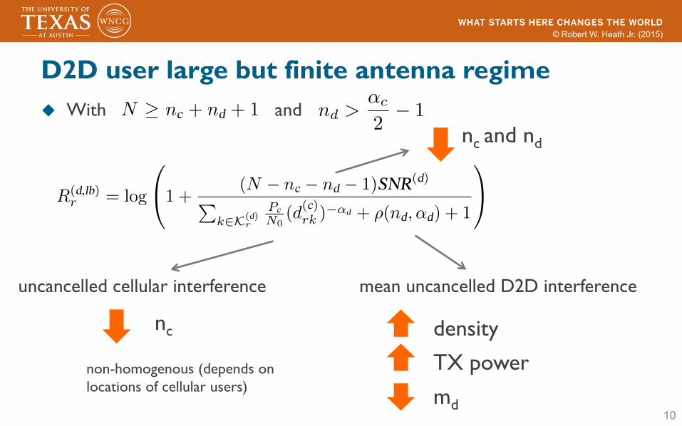
D2D user large but finite antenna regime u With and
10
uncancelled cellular interference mean uncancelled D2D interference
density TX power md
nc
nc and nd
where the expectation is taken with respect to the fast fadingand the random locations of D2D transmitters.
As the number N of antennas at the UE is often limiteddue to hardware constraints, it is not very meaningful to studythe asymptotic performance with N ! 1. Instead, as in thecase of cellular spectral efficiency, we provide a lower boundfor R(d)
r
in the non-asymptotic regime, which characterizes theimpact of the various system parameters on the D2D spectralefficiency.
Proposition 4. With perfect CSI, N � n
c
+ n
d
+ 1 and n
d
>
↵
d
2 �1, the spectral efficiency R
(d)r
of D2D Tx-Rx pair r is lower
bounded by
R
(d,lb)r
= log
0
@1 +
(N � n
c
� n
d
� 1)SNR
(d)
Pk2K(d)
r
P
c
N0(d
(c)rk
)
�↵
d
+ ⇢(n
d
,↵
d
) + 1
1
A,
(19)
where SNR
(d)= P
d
d
�↵
d
/N0 and ⇢(m,↵) is defined in (12).
Proof: The proof is similar to that of Prop. 3.Many of the remarks on Prop. 3 apply to Prop. 4 as well
and are not repeated here. One additional remark is that thecellular-to-D2D interference is not homogeneous: differentD2D receivers experience different levels of cellular interfer-ence depending on their locations relative to the locations ofthe cellular transmitters (which are fixed in our model).
V. SIMULATION AND NUMERICAL RESULTS
In this section, we provide some simulation and numericalresults. The specific parameters used are summarized in TableI unless otherwise specified. The pathloss parameters givenin Table I corresponds to a carrier frequency of 2 GHz.Specifically, we use the 3GPP macrocell propagation model(urban area) for UE-BS channels and the revised Winner +
B1 model (non-light-of-sight with �5 dB offset) for UE-UEchannels. In the simulation, the BS is located at the origin. Asa benchmark, we fix the 4 cellular UE positions at (R
c
/2, 0
o
),(R
c
, 0
o
), (Rc
, 120
o
), and (R
c
, 240
o
) unless otherwise stated;here R
c
is the coverage radius of the BS. The cellular spectralefficiency plotted is the average cellular spectral efficiency ofthe 4 cellular UEs, while the D2D spectral efficiency plottedis from the D2D pair with the transmitter and the receiverrespectively located at (R
c
/2� d, 180
o
) and (R
c
/2, 180
o
).We first compare the simulated cellular spectral efficiency to
the corresponding analytical lower bound (14) under variousPZF parameters (mc,md) in Fig. 1. As shown in Fig. 1, theanalytical lower bound (14) closely matches the simulationresults. The larger md, the closer match between the simulationand the analytical lower bound (14). Note that mc = 0
and mc = 3 correspond to MRC and ZF (w.r.t. cellularUEs), respectively. Comparing the spectral efficiency with(mc,md) = (0, 2) to that of (mc,md) = (3, 2), we can see thatZF has much better performance and the spectral efficiencygain is about 3 bps/Hz. This observation implies that althoughasymptotically ZF and MRC have similar performance, it is
BS coverage radius R
c
500 mD2D link length d 20 m# cellular UEs K 4
Density of D2D UEs �
4⇡R
2c
m�2
# BS antennas M 100
# UE Rx antennas N 6
UE-BS PL exponent ↵c 3.76
UE-UE PL exponent ↵d 4.37
UE-BS PL reference Cc,0 15.3 dBUE-UE PL reference Cd,0 38.5 dBCellular Tx power Pc 23 dBmD2D Tx power Pd 13 dBmChannel bandwidth 10 MHzNoise PSD �174 dBm/HzBS noise figure 6 dBUE noise figure 9 dB
TABLE ISIMULATION/NUMERICAL PARAMETERS
50 100 150 200 250 300 350 400 450 5000
1
2
3
4
5
6
7
8
9
10
M: # of BS Antennas
Sp
ectr
al E
ffic
ien
cy (
bit/s
/Hz)
Lower bound: (mc,m
d)=(0,2)
Simulation: (mc,m
d)=(0,2)
Lower bound: (mc,m
d)=(1,2)
Simulation: (mc,m
d)=(1,2)
Lower bound: (mc,m
d)=(3,2)
Simulation: (mc,m
d)=(3,2)
Lower bound: (mc,m
d)=(3,3)
Simulation: (mc,m
d)=(3,3)
Fig. 1. Simulated cellular spectral efficiency vs. analytical lower bound (14).
still quite beneficial to appropriately suppress the co-channelcellular interference in practical non-asymptotic regime.
Since the lower bound (14) is accurate, next we use itto demonstrate the cellular spectral efficiency with scaledcellular transmit power (i.e., Pc ! Pc/M ) in Fig. 2. Weconsider two PZF choices: PZF with constant md and PZFwith scaled md = ⇥(
pM). As a benchmark, we also include
the curves corresponding the scenarios without D2D underlay.Several observations about Fig. 2 are in order. First, unlikethe case with unscaled cellular transmit power, Fig. 2 showsthat ZF and MRC have similar performance even with amoderate number of BS antennas. Second, adopting a constantmd results in a fixed loss in the cellular spectral efficiencydue to the underlaid D2D interference; this loss cannot beovercome by increasing the number of BS antennas when thecellular transmit power is also scaled down as ⇥(1/M). Thisobservation confirms the analytical results in Prop. 2. Third,the loss in the cellular spectral efficiency due to D2D underlay
5965
nd >↵c
2� 1
where the expectation is taken with respect to the fast fadingand the random locations of D2D transmitters.
As the number N of antennas at the UE is often limiteddue to hardware constraints, it is not very meaningful to studythe asymptotic performance with N ! 1. Instead, as in thecase of cellular spectral efficiency, we provide a lower boundfor R(d)
r
in the non-asymptotic regime, which characterizes theimpact of the various system parameters on the D2D spectralefficiency.
Proposition 4. With perfect CSI, N � n
c
+ n
d
+ 1 and n
d
>
↵
d
2 �1, the spectral efficiency R
(d)r
of D2D Tx-Rx pair r is lower
bounded by
R
(d,lb)r
= log
0
@1 +
(N � n
c
� n
d
� 1)SNR
(d)
Pk2K(d)
r
P
c
N0(d
(c)rk
)
�↵
d
+ ⇢(n
d
,↵
d
) + 1
1
A,
(19)
where SNR
(d)= P
d
d
�↵
d
/N0 and ⇢(m,↵) is defined in (12).
Proof: The proof is similar to that of Prop. 3.Many of the remarks on Prop. 3 apply to Prop. 4 as well
and are not repeated here. One additional remark is that thecellular-to-D2D interference is not homogeneous: differentD2D receivers experience different levels of cellular interfer-ence depending on their locations relative to the locations ofthe cellular transmitters (which are fixed in our model).
V. SIMULATION AND NUMERICAL RESULTS
In this section, we provide some simulation and numericalresults. The specific parameters used are summarized in TableI unless otherwise specified. The pathloss parameters givenin Table I corresponds to a carrier frequency of 2 GHz.Specifically, we use the 3GPP macrocell propagation model(urban area) for UE-BS channels and the revised Winner +
B1 model (non-light-of-sight with �5 dB offset) for UE-UEchannels. In the simulation, the BS is located at the origin. Asa benchmark, we fix the 4 cellular UE positions at (R
c
/2, 0
o
),(R
c
, 0
o
), (Rc
, 120
o
), and (R
c
, 240
o
) unless otherwise stated;here R
c
is the coverage radius of the BS. The cellular spectralefficiency plotted is the average cellular spectral efficiency ofthe 4 cellular UEs, while the D2D spectral efficiency plottedis from the D2D pair with the transmitter and the receiverrespectively located at (R
c
/2� d, 180
o
) and (R
c
/2, 180
o
).We first compare the simulated cellular spectral efficiency to
the corresponding analytical lower bound (14) under variousPZF parameters (mc,md) in Fig. 1. As shown in Fig. 1, theanalytical lower bound (14) closely matches the simulationresults. The larger md, the closer match between the simulationand the analytical lower bound (14). Note that mc = 0
and mc = 3 correspond to MRC and ZF (w.r.t. cellularUEs), respectively. Comparing the spectral efficiency with(mc,md) = (0, 2) to that of (mc,md) = (3, 2), we can see thatZF has much better performance and the spectral efficiencygain is about 3 bps/Hz. This observation implies that althoughasymptotically ZF and MRC have similar performance, it is
BS coverage radius R
c
500 mD2D link length d 20 m# cellular UEs K 4
Density of D2D UEs �
4⇡R
2c
m�2
# BS antennas M 100
# UE Rx antennas N 6
UE-BS PL exponent ↵c 3.76
UE-UE PL exponent ↵d 4.37
UE-BS PL reference Cc,0 15.3 dBUE-UE PL reference Cd,0 38.5 dBCellular Tx power Pc 23 dBmD2D Tx power Pd 13 dBmChannel bandwidth 10 MHzNoise PSD �174 dBm/HzBS noise figure 6 dBUE noise figure 9 dB
TABLE ISIMULATION/NUMERICAL PARAMETERS
50 100 150 200 250 300 350 400 450 5000
1
2
3
4
5
6
7
8
9
10
M: # of BS Antennas
Spect
ral E
ffic
iency
(bit/
s/H
z)
Lower bound: (mc,m
d)=(0,2)
Simulation: (mc,m
d)=(0,2)
Lower bound: (mc,m
d)=(1,2)
Simulation: (mc,m
d)=(1,2)
Lower bound: (mc,m
d)=(3,2)
Simulation: (mc,m
d)=(3,2)
Lower bound: (mc,m
d)=(3,3)
Simulation: (mc,m
d)=(3,3)
Fig. 1. Simulated cellular spectral efficiency vs. analytical lower bound (14).
still quite beneficial to appropriately suppress the co-channelcellular interference in practical non-asymptotic regime.
Since the lower bound (14) is accurate, next we use itto demonstrate the cellular spectral efficiency with scaledcellular transmit power (i.e., Pc ! Pc/M ) in Fig. 2. Weconsider two PZF choices: PZF with constant md and PZFwith scaled md = ⇥(
pM). As a benchmark, we also include
the curves corresponding the scenarios without D2D underlay.Several observations about Fig. 2 are in order. First, unlikethe case with unscaled cellular transmit power, Fig. 2 showsthat ZF and MRC have similar performance even with amoderate number of BS antennas. Second, adopting a constantmd results in a fixed loss in the cellular spectral efficiencydue to the underlaid D2D interference; this loss cannot beovercome by increasing the number of BS antennas when thecellular transmit power is also scaled down as ⇥(1/M). Thisobservation confirms the analytical results in Prop. 2. Third,the loss in the cellular spectral efficiency due to D2D underlay
5965
non-homogenous (depends on locations of cellular users)

© Robert W. Heath Jr. (2015)
11
Cellular user performance comparison
50 100 150 200 250 300 350 400 450 5000
0.5
1
1.5
2
2.5
M: # of BS Antennas
Spect
ral E
ffic
iency
(bit/
s/H
z)
mc = 0, No D2D
(mc,m
d) = (0,2)
(mc,m
d) = (0, M1/2)
mc=3, No D2D
(mc,m
d) = (3,2)
(mc,m
d) = (3, M1/2)
Fig. 2. Cellular spectral efficiency with scaled cellular transmit power.
4 6 8 10 12 140
1
2
3
4
5
6
7
8
N: # of UE Rx Antennas
Spect
ral E
ffic
iency
(bit/
s/H
z)
Lower bound: d=20 mSimulation: d=20 mLower bound: d=25 mSimulation: d=25 mLower bound: d=30 mSimulation: d=30 mLower bound: d=35 mSimulation: d=35 m
Fig. 3. Simulated D2D spectral efficiency vs. analytical lower bound (19)with (nc, nd) = (0, 2).
can be overcome by scaling md at a sublinear rate ⇥(
pM).
Fig. 3 compares the simulated D2D spectral efficiency tothe corresponding analytical lower bound (19) under differentD2D distances and (nc, nd) = (0, 2). As shown in Fig. 3, theanalytical lower bound (19) closely matches the simulationresults when N � 6 while being a bit loose when N < 6. Theaccuracy of the lower bound obtained from Jensen’s inequalityimplies that after canceling 2 nearest D2D interferers, thevariance of the remaining interference is relatively small. Fig.3 also shows that D2D spectral efficiency is quite sensitive toits communication range.
VI. CONCLUSIONS
In this paper, we have studied the spectral efficiency of aD2D underlaid massive MIMO system with perfect CSI. In theasymptotic regime where the number of BS antennas M ! 1,we find that the received SINR of any cellular user increasesunboundedly and the effects of noise, fast fading, and theinterfering signals from the other co-channel cellular users andthe infinite D2D transmitters vanish completely. Equivalently,it is possible to reduce cellular transmit power as ⇥(1/M)
but still achieve a non-vanishing cellular spectral efficiency.Compared to the case without D2D, there is a loss in cellularspectral efficiency if a constant number of D2D interferingsignals is canceled. The loss can be overcome if the numberof canceled D2D interfering signals is scaled appropriately(e.g. ⇥(logM) or ⇥(
pM)). In the non-asymptotic regime, we
have derived simple analytical lower bounds for both cellularand D2D spectral efficiency; the derived bounds allow forvery efficient numerical evaluation. Future work may considerother more sophisticated receivers like MMSE receivers andlinear receivers with successive interference cancellation andcompare their system-level performance with that of PZFreceivers studied in this paper.
REFERENCES
[1] 3GPP, “3rd generation partnership project; technical specification groupradio access network; study on LTE device to device proximity services;radio aspects (release 12),” TR 36.843 V12.0.1, March 2014.
[2] X. Lin, J. G. Andrews, A. Ghosh, and R. Ratasuk, “An overview of 3GPPdevice-to-device proximity services,” IEEE Communications Magazine,vol. 52, no. 4, pp. 40–48, April 2014.
[3] T. L. Marzetta, “Noncooperative cellular wireless with unlimited num-bers of base station antennas,” IEEE Transactions on Wireless Commu-
nications, vol. 9, no. 11, pp. 3590–3600, November 2010.[4] J. Hoydis, S. ten Brink, and M. Debbah, “Massive MIMO in the UL/DL
of cellular networks: How many antennas do we need?” IEEE Journal on
Selected Areas in Communications, vol. 31, no. 2, pp. 160–171, February2013.
[5] P. Janis, V. Koivunen, C. B. Ribeiro, K. Doppler, and K. Hugl,“Interference-avoiding MIMO schemes for device-to-device radio un-derlaying cellular networks,” in Proceedings of IEEE PIMRC, 2009, pp.2385–2389.
[6] H. Tang, C. Zhu, and Z. Ding, “Cooperative MIMO precoding for D2Dunderlay in cellular networks,” in Proceedings of IEEE ICC, 2013, pp.5517–5521.
[7] J. C. Li, M. Lei, and F. Gao, “Device-to-device (D2D) communicationin MU-MIMO cellular networks,” in Proceedings of IEEE Globecom,2012, pp. 3583–3587.
[8] H. Min, J. Lee, S. Park, and D. Hong, “Capacity enhancement using aninterference limited area for device-to-device uplink underlaying cellularnetworks,” IEEE Transactions on Wireless Communications, vol. 10,no. 12, pp. 3995–4000, December 2011.
[9] M. da S Rego, T. F. Maciel, H. de HM Barros, F. R. P. Cavalcanti,and G. Fodor, “Performance analysis of power control for device-to-device communication in cellular MIMO systems,” in Proceedings of
IEEE ISWCS, 2012, pp. 336–340.[10] S. Shalmashi, E. Bjornson, S. B. Slimane, and M. Debbah, “Closedform
optimality characterization of network-assisted device-to-device commu-nications,” in Proceedings of IEEE WCNC, 2014, pp. 508–513.
[11] X. Lin, R. W. Heath Jr, and J. G. Andrews, “The interplay be-tween massive MIMO and underlaid D2D networking,” IEEE Trans-
actions on Wireless Communications, to appear, 2015. Available athttp://arxiv.org/abs/1409.2792v3.
[12] X. Lin, R. Ratasuk, A. Ghosh, and J. G. Andrews, “Modeling, analysisand optimization of multicast device-to-device transmissions,” IEEE
Transactions on Wireless Communications, vol. 13, no. 8, pp. 4346–4359, August 2014.
[13] N. Jindal, J. G. Andrews, and S. Weber, “Multi-antenna communicationin ad hoc networks: Achieving MIMO gains with SIMO transmission,”IEEE Transactions on Communications, vol. 59, no. 2, pp. 529–540,February 2011.
[14] T. Bai and R. W. Heath Jr, “Asymptotic coverage probability andrate in massive MIMO networks,” in Proceedings of IEEE GlobalSIP,December 2014.
[15] H. Q. Ngo, E. Larsson, and T. Marzetta, “Energy and spectral efficiencyof very large multiuser MIMO systems,” IEEE Transactions on Com-
munications, vol. 61, no. 4, pp. 1436–1449, April 2013.
5966
where the expectation is taken with respect to the fast fadingand the random locations of D2D transmitters.
As the number N of antennas at the UE is often limiteddue to hardware constraints, it is not very meaningful to studythe asymptotic performance with N ! 1. Instead, as in thecase of cellular spectral efficiency, we provide a lower boundfor R(d)
r
in the non-asymptotic regime, which characterizes theimpact of the various system parameters on the D2D spectralefficiency.
Proposition 4. With perfect CSI, N � n
c
+ n
d
+ 1 and n
d
>
↵
d
2 �1, the spectral efficiency R
(d)r
of D2D Tx-Rx pair r is lower
bounded by
R
(d,lb)r
= log
0
@1 +
(N � n
c
� n
d
� 1)SNR
(d)
Pk2K(d)
r
P
c
N0(d
(c)rk
)
�↵
d
+ ⇢(n
d
,↵
d
) + 1
1
A,
(19)
where SNR
(d)= P
d
d
�↵
d
/N0 and ⇢(m,↵) is defined in (12).
Proof: The proof is similar to that of Prop. 3.Many of the remarks on Prop. 3 apply to Prop. 4 as well
and are not repeated here. One additional remark is that thecellular-to-D2D interference is not homogeneous: differentD2D receivers experience different levels of cellular interfer-ence depending on their locations relative to the locations ofthe cellular transmitters (which are fixed in our model).
V. SIMULATION AND NUMERICAL RESULTS
In this section, we provide some simulation and numericalresults. The specific parameters used are summarized in TableI unless otherwise specified. The pathloss parameters givenin Table I corresponds to a carrier frequency of 2 GHz.Specifically, we use the 3GPP macrocell propagation model(urban area) for UE-BS channels and the revised Winner +
B1 model (non-light-of-sight with �5 dB offset) for UE-UEchannels. In the simulation, the BS is located at the origin. Asa benchmark, we fix the 4 cellular UE positions at (R
c
/2, 0
o
),(R
c
, 0
o
), (Rc
, 120
o
), and (R
c
, 240
o
) unless otherwise stated;here R
c
is the coverage radius of the BS. The cellular spectralefficiency plotted is the average cellular spectral efficiency ofthe 4 cellular UEs, while the D2D spectral efficiency plottedis from the D2D pair with the transmitter and the receiverrespectively located at (R
c
/2� d, 180
o
) and (R
c
/2, 180
o
).We first compare the simulated cellular spectral efficiency to
the corresponding analytical lower bound (14) under variousPZF parameters (mc,md) in Fig. 1. As shown in Fig. 1, theanalytical lower bound (14) closely matches the simulationresults. The larger md, the closer match between the simulationand the analytical lower bound (14). Note that mc = 0
and mc = 3 correspond to MRC and ZF (w.r.t. cellularUEs), respectively. Comparing the spectral efficiency with(mc,md) = (0, 2) to that of (mc,md) = (3, 2), we can see thatZF has much better performance and the spectral efficiencygain is about 3 bps/Hz. This observation implies that althoughasymptotically ZF and MRC have similar performance, it is
BS coverage radius R
c
500 mD2D link length d 20 m# cellular UEs K 4
Density of D2D UEs �
4⇡R
2c
m�2
# BS antennas M 100
# UE Rx antennas N 6
UE-BS PL exponent ↵c 3.76
UE-UE PL exponent ↵d 4.37
UE-BS PL reference Cc,0 15.3 dBUE-UE PL reference Cd,0 38.5 dBCellular Tx power Pc 23 dBmD2D Tx power Pd 13 dBmChannel bandwidth 10 MHzNoise PSD �174 dBm/HzBS noise figure 6 dBUE noise figure 9 dB
TABLE ISIMULATION/NUMERICAL PARAMETERS
50 100 150 200 250 300 350 400 450 5000
1
2
3
4
5
6
7
8
9
10
M: # of BS Antennas
Sp
ect
ral E
ffic
ien
cy (
bit/
s/H
z)
Lower bound: (mc,m
d)=(0,2)
Simulation: (mc,m
d)=(0,2)
Lower bound: (mc,m
d)=(1,2)
Simulation: (mc,m
d)=(1,2)
Lower bound: (mc,m
d)=(3,2)
Simulation: (mc,m
d)=(3,2)
Lower bound: (mc,m
d)=(3,3)
Simulation: (mc,m
d)=(3,3)
Fig. 1. Simulated cellular spectral efficiency vs. analytical lower bound (14).
still quite beneficial to appropriately suppress the co-channelcellular interference in practical non-asymptotic regime.
Since the lower bound (14) is accurate, next we use itto demonstrate the cellular spectral efficiency with scaledcellular transmit power (i.e., Pc ! Pc/M ) in Fig. 2. Weconsider two PZF choices: PZF with constant md and PZFwith scaled md = ⇥(
pM). As a benchmark, we also include
the curves corresponding the scenarios without D2D underlay.Several observations about Fig. 2 are in order. First, unlikethe case with unscaled cellular transmit power, Fig. 2 showsthat ZF and MRC have similar performance even with amoderate number of BS antennas. Second, adopting a constantmd results in a fixed loss in the cellular spectral efficiencydue to the underlaid D2D interference; this loss cannot beovercome by increasing the number of BS antennas when thecellular transmit power is also scaled down as ⇥(1/M). Thisobservation confirms the analytical results in Prop. 2. Third,the loss in the cellular spectral efficiency due to D2D underlay
5965
no D2D
canceling fixed # D2D users
canceling increasing # D2D users

© Robert W. Heath Jr. (2015)
12
Cellular spectral efficiency
Perfect CSI Imperfect CSI Imperfect CSI w/ inac7ve D2D in the
training
W/ constant cellular TX power
Unbounded Bounded and reduced due to
D2D underlay contamina;on
Bounded and no effect of D2D
underlay
W/ scaled cellular TX power
Scaling law: 1/M Should not be scaled down
Scaling law: 1/M0.5
D2D-‐to-‐cellular interference can be
eliminated by scaling up md
Scaled cellular TX power results in vanishing spectral
efficiency
D2D-‐to-‐cellular interference in the data transmission persists
X. Lin, R. W. Heath Jr., and J. G. Andrews, ‘‘The interplay between massive MIMO and underlaid D2D networking,’’ IEEE Transac*ons on Wireless Communica*ons, to appear.

© Robert W. Heath Jr. (2015)
References u Stochastic geometry for cellular [Andrews11] J. G. Andrews, F. Baccelli, and R. K. Ganti, "A tractable approach to coverage and rate in cellular networks", IEEE
TCom, vol. 59, no. 11, pp. 3122-34, nov. 2011. [Dhilon12] H. Dhillon, R. K. Ganti, F. Baccelli, and J. G. Andrews, "Modeling and analysis of K-tier downlink heterogeneous
cellular networks", IEEE JSAC, vol. 30, no. 3, pp. 550 – 560, Apr. 2012. [Heath13] R. W. Heath, Jr., M. Kountouris, and T. Bai`` Modeling heterogeneous network interference using Poisson point
processes ,'' IEEE Trans. on Signal Processing, vol. 61, no. 16, pp. 4114-4126, Aug. 2013.
u Massive MIMO [Marzetta10] T. L. Marzetta, “Noncooperative cellular wireless with unlimited numbers of base station antennas,” IEEE Twireless,
vol. 9, no. 11, pp. 3590–3600, Nov. 2010. [Huh12] H. Huh, G. Caire, H. C. Papadopoulos, and S. A. Ramprashad, “Achieving massive MIMO spectral efficiency with a not-
so-large number of antennas,” IEEE TWireless, vol. 11, no. 9, pp. 3226–3239, Sep. 2012. [Ngo13] H. Q. Ngo, E. Larsson, and T. Marzetta, “Energy and spectral efficiency of very large multiuser MIMO systems,” IEEE
TCom, vol. 61, no. 4, pp. 1436–1449, Apr. 2013. [Hoydis3] J. Hoydis, S. ten Brink, and M. Debbah, “Massive MIMO in the UL/DL of cellular networks: How many antennas do
we need?” IEEE JSAC, vol. 31, no. 2, pp. 160–171, February 2013. [Truong13] K. T. Truong and R. W. Heath, Jr., “Effects of channel aging in massive MIMO systems,” Journal of Communications and
Networks, Special Issue on Massive MIMO, vol. 15, no. 4, pp. 338-351, August 2013.
13
© Robert W. Heath Jr. (2015)
References
14
u Massive MIMO (cont’d) [Madhu13] P. Madhusudhanan, X. Li, Y. Liu, and T. Brown, “Stochastic geometric modeling and interference analysis for massive
MIMO systems,” in Proceedings of WiOpt, May 2013, pp. 15–22. [Bai14] T.Bai and R. W. Heath Jr, “Asymptotic coverage probability and rate in massive MIMO networks,” in Proceedings of
IEEE GlobalSIP, December 2014, pp. 1-5. [Liang15] N. Liang, W. Zhang, and C. Shen, “An uplink interference analysis for massive MIMO systems with MRC and ZF
receivers,” Proc. of WCNC, 2015.
u D2D [Wu13] X. Wu, S. Tavildar, S. Shakkottai, T. Richardson, J. Li, R. Laroia, and A. Jovicic, “FlashLinQ: A synchronous distributed
scheduler for peer-to-peer ad hoc networks,” IEEE/ACM Trans. Networking, vol. 21, no. 4, pp. 1215–1228, Aug. 2013. [Lin14] X. Lin, R. Ratasuk, A. Ghosh, and J. G. Andrews, ‘‘Modeling, analysis and optimization of multicast device-to-device
transmissions,’’ IEEE TWireless, vol. 13, no. 8, pp. 4346-4359, Aug. 2014. [Janis09] P. Janis, V. Koivunen, C. B. Ribeiro, K. Doppler, and K. Hugl, “Interference-avoiding MIMO schemes for device-
to-device radio underlaying cellular networks,” in Proceedings of IEEE PIMRC, 2009, pp. 2385–2389. [Min11] H. Min, J. Lee, S. Park, and D. Hong, “Capacity enhancement using an interference limited area for device-to-
device uplink underlaying cellular networks,” IEEE TWireless, vol. 10, no. 12, pp. 3995–4000, Dec. 2011.
u Massive MIMO + D2D [Yin14] H. Yin, L. Cottatellucci, D. Gesbert, "Enabling Massive MIMO Systems in the FDD Mode thanks to D2D
Communications", in Proc. of the Asilomar Conference on Signals, Systems, and Computers, Nov. 2014.