spectre mars - the mars...
TRANSCRIPT
The Mars Society
Inspiration Mars International Student Design Competition
University of Glasgow, Scotland, United Kingdom
SPECTRE MARS

2
Team Description:
The team consists of eight Undergraduate Aero-Engineering students from the Student
Aerospace Engineering Society (SAES), University of Glasgow, Scotland, United Kingdom.
The complete list is given below:
Member Project Job Title Email
Ahmad, Taseer Team Leader Manager Organiser
Ammar, Ahmed Launch System Structures
Kamara, Ahmed Thermal Protection System Power Requirements
Lim, Gabriel Vehicle Health Management [email protected]
Magowan, Caitlin Propulsion [email protected]
Todorova, Blaga Propulsion [email protected]
Tse, Yee Cheung Trajectory Avionics Fuel Tanks
White, Tom Reaction Control System Human Effects Ground Systems

3
Contents 1. Abstract .................................................................................................................................. 6
2. Trajectory ............................................................................................................................... 7
3. Aerodynamics and Structure ............................................................................................... 10
3.1 Space Launch System ..................................................................................................... 10
3.1.1. Introduction............................................................................................................ 10
3.1.2. Capabilities ............................................................................................................. 10
3.1.3. Design and Development ....................................................................................... 11
3.1.3.1. Core Stage ........................................................................................................... 11
3.1.3.2. Booster cores ....................................................................................................... 11
3.1.3.3. Upper stage / Interstage ..................................................................................... 11
3.1.4. Assembled Rocket ...................................................................................................... 11
3.1.5. Program Costs ............................................................................................................ 11
3.2. Orion (Spacecraft) ......................................................................................................... 12
3.2.1. Introduction............................................................................................................ 12
3.2.2. Crew module .......................................................................................................... 12
3.2.3. ATV based service module ..................................................................................... 13
3.6.4 Launch Abort systems (LAS) .................................................................................... 13
4. Propulsion ............................................................................................................................ 14
4.1 Introduction ................................................................................................................... 14
4.2 Engines considered ........................................................................................................ 14
4.2.1 Solar Electric ............................................................................................................ 14
4.2.2. Air Breathing .......................................................................................................... 15
4.2.3. Chemical ................................................................................................................. 16
4.3. Merlin 1D Rocket Engine............................................................................................... 17
4.3.1 Characteristics and performance ............................................................................ 17
4.3.2. How it works?......................................................................................................... 18
4.4. Cost ............................................................................................................................... 19
4.5. Development of Merlin 1 rocket engine. ...................................................................... 20
4.6. Conclusion ..................................................................................................................... 22
5. Fuel Tank and piping system ................................................................................................ 23
5.1. Introduction .................................................................................................................. 23

4
5.2. Fuel and oxidizer Description ........................................................................................ 23
5.3. Material ......................................................................................................................... 26
5.4. From Earth Orbit to Mars .............................................................................................. 27
5.4. From Earth to orbit ....................................................................................................... 29
6. Reaction Control Systems .................................................................................................... 31
6.1. Propellant Selection ...................................................................................................... 31
6.2. XR-3N22 Lynx RCS Engine ............................................................................................. 31
6.3. Apollo Reaction Control System ................................................................................... 32
6.4. Selection of Engine and Fuel ......................................................................................... 32
6.5. Positioning of Systems .................................................................................................. 33
6.5.1. Orbiter .................................................................................................................... 33
6.5.2. Boosters ................................................................................................................. 33
6.5.3. Cost and weight ..................................................................................................... 33
7. Thermal Protection System.................................................................................................. 34
7.1. Why do we need one? .................................................................................................. 34
7.2. Current available recommendations ............................................................................ 34
7.3. ASTRA ULTIMATE .......................................................................................................... 35
7.3.1. Testing .................................................................................................................... 36
7.3.2. Loading ................................................................................................................... 36
7.3.3. Maintenance .......................................................................................................... 36
7.4. Cost ............................................................................................................................... 37
7.5. Appendix ....................................................................................................................... 37
7.5.1. Maintenance Flow Chart: ....................................................................................... 37
8. Avionics ................................................................................................................................ 38
8.1. On board computers: CPU (Mongoose-V) .................................................................... 38
8.2. Remote Terminal Units(RTU) ........................................................................................ 38
8.3. Command and Data Handling (C &DH) ......................................................................... 38
8.4. Onboard buses and data networks ............................................................................... 38
8.5. Navigation and guidance .............................................................................................. 39
9. Vehicle Health Management ............................................................................................... 40
9.1. Pyrometer ..................................................................................................................... 40
9.2. Isotope Wear Detector ................................................................................................. 40

5
9.3. Fiber-optic Deflectometer ............................................................................................ 40
9.4. Spectrometer ................................................................................................................ 40
9.5. Integrated Vehicle Health Management ...................................................................... 41
9.6. Structure ....................................................................................................................... 41
9.6.1. Data Acquisition ..................................................................................................... 41
9.6.2. Data Manipulation ................................................................................................. 42
9.6.3. State Detection ...................................................................................................... 42
9.6.4. Health Assessment ................................................................................................. 43
8.6.5. Prognosis Assessment ............................................................................................ 43
8.6.6. Advisory Generation ............................................................................................... 44
9.7. Engine Management ..................................................................................................... 44
9.7.1. Problems ................................................................................................................ 44
9.7.2. Solution .................................................................................................................. 45
9.8. Cost ............................................................................................................................... 45
10. Human Factors ................................................................................................................... 46
10.1. Food ............................................................................................................................ 46
10.2. Human Health ............................................................................................................. 46
10.3. Psychological Impact ................................................................................................... 46
11. Ground Systems ................................................................................................................. 47
12. Power ................................................................................................................................. 49
12.1. Why is power important? ........................................................................................... 49
12.2. Power and Energy Requirements ............................................................................... 49
12.3. Avionics ....................................................................................................................... 49
12.4. Integrated Vehicle Health Management .................................................................... 49
12.5. Reaction Control ......................................................................................................... 50
12.6. Human Effects ............................................................................................................. 50

6
1. Abstract
The team’s design concept (SPECTRE MARS) is a partially re-usable, two stage launch vehicle
that consists of the NASA SLS and Orion spacecraft with 28 Merlin 1D engines, 27 for the
first stage and one for the second. Two cores of nine engines each, from the specified
numbers of engines, will be used in the booster cores.
Fuel tanks and piping system will be using liquid oxygen as the fuel and liquid kerosene as
the oxidizer. The Reaction Control System chosen for the project is Lynx RCS which uses a bi-
propellant fuel.
Thermal Protection System chosen for the project is ASTRA ULTIMATE which is still under
testing but the results have been very promising. This system, upon completion, will be the
best such system up to date.
The Avionics for the project will consist of on board computers (Mongoose V), Remote
Terminal Units (RTU), Command and Data Handling (C & DH), On board data buses and a
Navigation and Guidance System (DSN Deep Space System)
The advanced vehicle health management system will comply by all the rules of an
integrated vehicle health management system. To strengthen this network, extra
monitoring devices have been added to the project. This system will also be extended to
handle any problems in the engine.
According to the design requirements, the spacecraft is manned. Thus requires systems on
board to cater for the humans and provide enough food to last for the length of whole
mission. Enough data has been provided for the human effect on the mission.
The trajectory of the mission is the most suitable for 2018 and includes a free-return to
earth, reducing the fuel required and thus reducing the cost of the mission. Existing launch
facilities in French Guyana will be used for ground systems, again saving mission costs. The
power requirements for the whole mission have also been covered.
There is a great expectation for humans to land on Mars in the next few decades, and this
mission may be the stepping stone to do so.
7
2. Trajectory
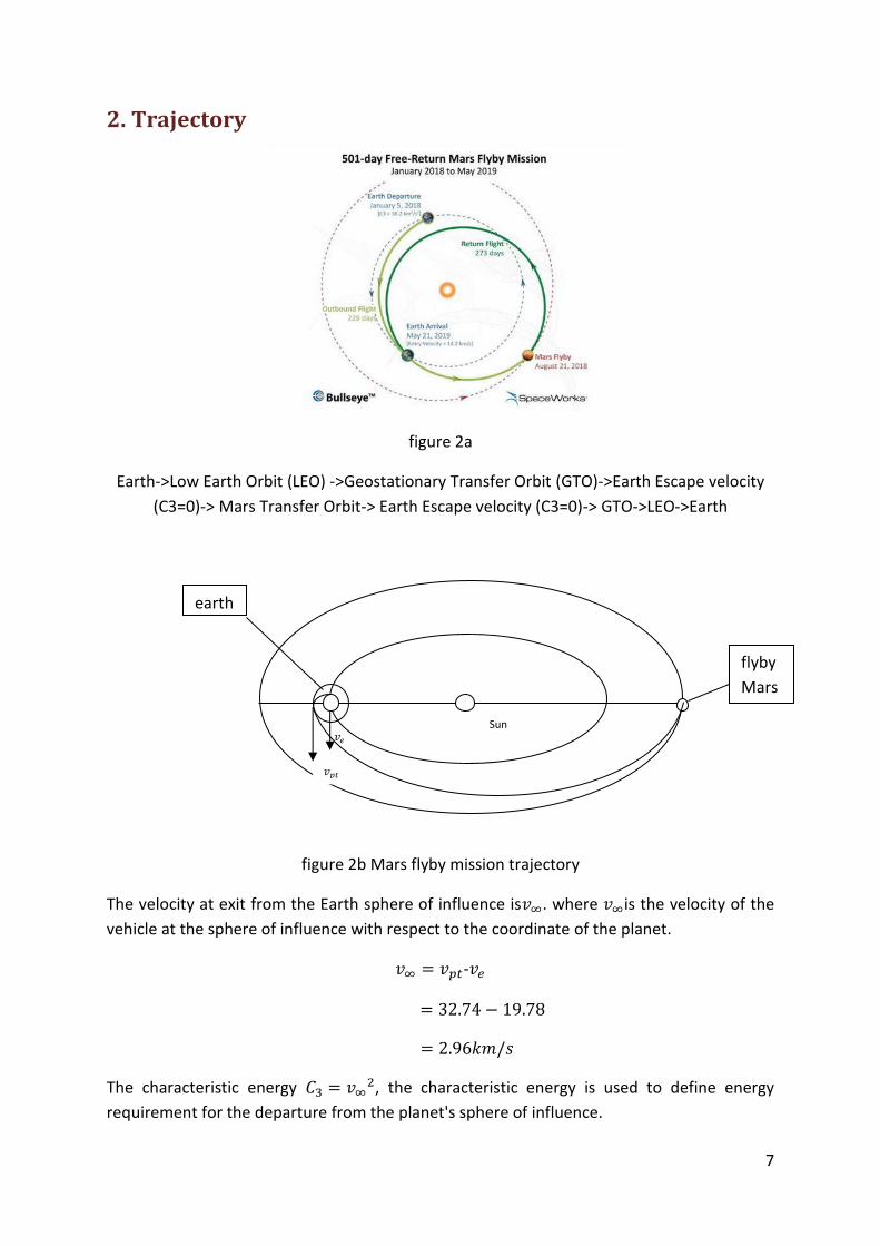
figure 2a
Earth->Low Earth Orbit (LEO) ->Geostationary Transfer Orbit (GTO)->Earth Escape velocity
(C3=0)-> Mars Transfer Orbit-> Earth Escape velocity (C3=0)-> GTO->LEO->Earth
figure 2b Mars flyby mission trajectory
The velocity at exit from the Earth sphere of influence is . where is the velocity of the
vehicle at the sphere of influence with respect to the coordinate of the planet.
-
The characteristic energy , the characteristic energy is used to define energy
requirement for the departure from the planet's sphere of influence.
Sun
flyby
Mars
earth

8
In this case, and the energy of the escape hyperbolic route will be
.
Assuming that there is an injection burn at an altitude of 300km with respect to the earth,
the burn out velocity required will be:
√
=radius of the earth at equator=6378km
h=altitude of injection burn=300km
=gravitational parameter of the earth=GM=3.9860064x
Energy to escape the hyberbola=4.83 .
Figure 2c flyby mission return trajectory
When the distance between the spacecraft and Mars is at the minimum, the velocity is
11.32 km/s.
Figure 2d forces on the spacecraft when it is orbiting the earth

9
By equating the centripetal force and gravitational force acting on the spacecraft, the
minimum velocity for a spacecraft to stay at the earth orbit of altitude h will be
√
For the spacecraft to stay at an altitude of 100km, =7.84 km/s. If the spacecraft is orbiting
at a velocity less than , then it will be attracted by the gravitational force and re-enter the
earth. Therefore, the spacecraft will need to decelerate from 11.32 km/s to 7.84km/s when
it returns from Mars to Earth's orbit.
Further trajectory calculations have been included in the fuel tanks and piping system for
the project.

10
3. Aerodynamics and Structure
3.1 Space Launch System
3.1.1. Introduction The Space Launch Systems (SLS), opening new doors for science and human exploration
beyond Earth’s orbit is an advanced heavy lift launch vehicle. Unique vantage points in
space are to be explored and, to cross current limits, we need means that are affordable,
sustainable and safe. The SLS gives us this opportunity. The SLS will carry the Orion Multi-
purpose crew vehicle. The Orion spacecraft can carry two to four astronauts and is designed
flexibly to support any type of mission be it deep
space exploration or service missions to the
International Space Station (ISS), which were
earlier carried out by the retired space shuttle
program.
The SLS includes the crew and service modules and
also the advanced Launch Abort system which
significantly increases the safety of the crew. The
SLS is flexible and evolves to perform any crew and
cargo missions as needed. With multiple lift vehicle
configurations the astronauts aboard the Orion
spacecraft can not only conduct deep space
explorations further into the solar system but also
possible find resources to develop new
technologies and answers to our position and role
in the universe.
3.1.2. Capabilities The SLS configuration proposed for this specific
mission is the “Block I”. It is a 70 metric ton launch vehicle which can lift more than 154,000
pounds (approximately 70,000kg) and provides 10 percent more thrust than the Saturn V
rocket. This configuration focuses on the use of proven hardware, tools and manufacturing
technologies. This will not only reduce the cost of the development and operation but also
increase safety and endurance of the flight and its systems. This heavy lift vehicle
configuration is 321 feet tall (approximately 98 meters) which is slightly shorter than the
Saturn V and provides 8.4 million pounds (3.8 million kg) of thrust at liftoff and weighs
around 5.5 million pounds (2.5 million kg).
This configuration of the SLS consists of 2 booster cores consisting of 9 Merlin engines each,
9 Merlin engines making up the core stage of the SLS. Further up is the interim cryogenic

11
propulsion stage, and then comes the Orion spacecraft docked into the Launch Abort
system.
3.1.3. Design and Development
3.1.3.1. Core Stage The core stage of the SLS mainly consists of five parts: the engine section, a kerosene tank,
an inter tank, a liquid oxygen tank and a forward skit. It measures more than 200 feet (61
meters) in length, having a diameter of 27.6 feet (8.4 meters). The empty core weighs more
than 85,275 kg and is built out of Aluminium 2219. The core carries the liquid hydrogen as a
fuel and liquid oxygen as an oxidiser to feed 9 Merlin engines. The Product design review
(PDR) confirms the design falls within the required budget constraints. The core stage is
being manufactured and assembled at Michaud Assembly facility in New Orleans.
3.1.3.2. Booster cores This particular configuration of the SLS will use two booster cores consisting of 9 Merlin
engines each.
3.1.3.3. Upper stage / Inter-stage This inter-stage consists of one Merlin engine whose sole purpose is to power the second
stage to a desired altitude and set the spacecraft in orbit to Mars.
3.1.4. Assembled Rocket The assembled rocket can remain at the launch pad for a minimum of 180 days and in
stacked configuration for at least 200 days.
3.1.5. Program Costs NASA predicts the program to cost about $3 billion yearly with total development costs
adding up to $35 billion. In order to get the SLS ready for its 2017 test launch, the cost
estimates to be about $18 billion with the rocket costing about 10 billion dollars, the Crew
capsule to cost about 6 billion dollars and the launch pad and ground facilities for the SLS
costing $2 billion.

12
3.2. Orion (Spacecraft)
3.2.1. Introduction Orion Multi-Purpose Crew Vehicle (MPCV) is a next generation deep space exploration
vehicle to be launched aboard the Space Launch Systems (SLS). It will execute long duration
missions to nearby asteroids and mars and return crew members to earth. The spacecraft is
capable of carrying two to four astronauts. It also
supports crew and cargo missions to the
International Space Station (ISS).
The Orion consists of four functional modules: the
launch abort system, the crew module, the service
module and the spacecraft adapter. The Launch
Abort system functions as the emergency escape
system during the launches, the crew module
transports the crew and the cargo, the service
module supports the propulsion and electrical
needs and the spacecraft adapter is a structural
transition which docks the spacecraft onto the SLS.
3.2.2. Crew module The design of the crew module is derived from the
earlier Apollo crew module. It features a 57.5 degree frustum shape. This particular shape
benefits to reduce the area required for thermal protection and also provides 10 time safety
during re-entry and deep space manoeuvrability. The diameter and length of the CM are
about 5 meters and 3 meters respectively and it weighs about 8500 kg. The major difference
between the CM and Apollo CM is that, the Orion CM is twice the size and carries at least
four crew members.
The Orion crew module also features a glass cockpit inspired from the Boeing 787. It
features the advanced digital controls and computerized systems including features like the
auto dock system. During emergency situations the crew is allowed to take over the controls
of docking. Among the new improved features is the waste management facility which is
described as a “unisex camping style toilet”, better preferred than the plastic “Apollo Bags”.
During re-entry the Orion crew module deploys recovery parachutes and features a splash
down landing into the ocean. The parachutes being used are similar the ones used in the
shuttle SRB’s and are made of Nomex. Nomex will also be used on areas with a possibility of
critical heating like the bay doors.

13
Orion crew module
3.2.3. ATV based service module The ATV-based service module will be featured in the future deep exploration missions into
the space. It provides the crew Module with propulsion and electrical needs. It also provides
the astronauts with supplies of gas and water. The service module features solar panels in
the form of x-rays and provides basic power needs. The four solar panels consist of 40Ah
rechargeable batteries and have a span of 22.3 meters. The power generated by theses
solar panels is 3800 watts. The crew module will re-enter the earth’s atmosphere at 11
kilometres per hour, the fastest ever.
3.6.4 Launch Abort systems (LAS) The LAS fairing consists of a lightweight composite structure similar to a graphite tennis
racquet weighing 3000 pounds (1360kg). The various parts of the Orion Launch Abort
system from the top are the nose cone, altitude control motor, canard section, Jettison
motor, inter-stage, abort motor and adapter cone which docks onto the crew module.
Between the crew module and the adapter cone, there are several boost protective covers
made of fiberglass to protect the CM from aerodynamic and impact stresses.
The abort motor consists of four nozzles
at a cant angle of 30 degrees and
provides a thrust of 2.25kN per nozzle.
The altitude motors consist of 8 nozzles
at cant angle of 90 degrees providing a
thrust of 11kN per nozzle. Lastly the
Jettison motor consists of 4 nozzles at a
Cant angle of 35 degrees providing a
thrust of 48kN per nozzle. The whole
system can carry 5468 pounds
(2480kg) of fuel.

14
4. Propulsion
4.1 Introduction The choice of the engine was made by considering the cost, technical quality and simplicity
as main objectives. The desire was to choose an engine with a strong research background
in recent years and is ready or will be ready before the required date, 2018, which will
increase the project feasibility. Therefore, the market research conducted was concentrated
on projects that will have finished their development soon.
4.2 Engines considered All the permissible kinds of engines for this competition were considered during the
research stage of this project, chemical, solar electric and air breathing.
4.2.1 Solar Electric Solar electric propulsion has never been tested, however, from earlier research it was
known there is an engine designed by Ad-astra, the VASIMR engine. The VASIMR engine is
currently in development and is due to undergo testing at the International Space Station in
2016.
15
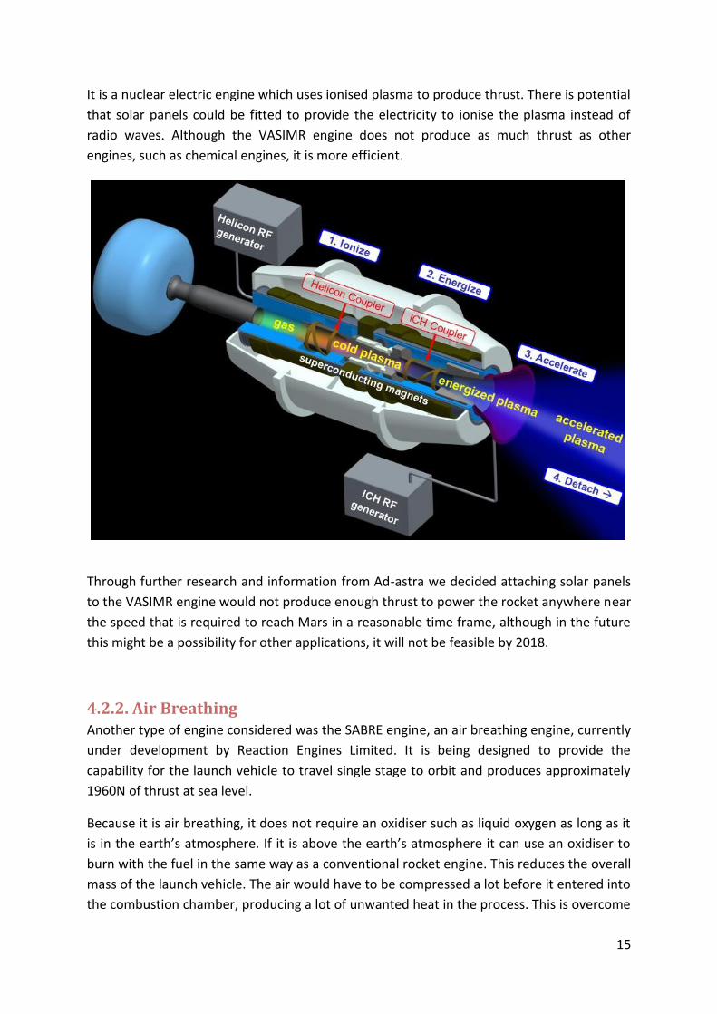
It is a nuclear electric engine which uses ionised plasma to produce thrust. There is potential
that solar panels could be fitted to provide the electricity to ionise the plasma instead of
radio waves. Although the VASIMR engine does not produce as much thrust as other
engines, such as chemical engines, it is more efficient.
Through further research and information from Ad-astra we decided attaching solar panels
to the VASIMR engine would not produce enough thrust to power the rocket anywhere near
the speed that is required to reach Mars in a reasonable time frame, although in the future
this might be a possibility for other applications, it will not be feasible by 2018.
4.2.2. Air Breathing Another type of engine considered was the SABRE engine, an air breathing engine, currently
under development by Reaction Engines Limited. It is being designed to provide the
capability for the launch vehicle to travel single stage to orbit and produces approximately
1960N of thrust at sea level.
Because it is air breathing, it does not require an oxidiser such as liquid oxygen as long as it
is in the earth’s atmosphere. If it is above the earth’s atmosphere it can use an oxidiser to
burn with the fuel in the same way as a conventional rocket engine. This reduces the overall
mass of the launch vehicle. The air would have to be compressed a lot before it entered into
the combustion chamber, producing a lot of unwanted heat in the process. This is overcome

16
using the engines cooling system to cool the air significantly before it is pressurised and
injected into the combustion chamber, preventing the engine from melting. It includes
technological advances such as frost control, which would be needed due to low
temperature the air will be cooled to, and light-weight technology.
The programme is definitely receiving funding for development up until 2016, but it is
unknown how long the programme will take to complete and when the engine will be ready
for use. For this reason it was decided not to use this engine in our project.
4.2.3. Chemical Chemical propulsion is by far the most common form of propulsion for rocket engines. The
F-1 engine, developed by Rocketdyne is the most powerful single chambered rocket engine
to ever be produced. These engines were used on the Saturn V, the launch vehicle for the
Apollo programme, the programme that enabled the first human landing on the moon. The
first F-1 engine started development in the late 1950’s and continued development during
the 1960’s whilst the original version of the engine was being used on Saturn V. The new
developments resulted in a new engine specification, the F-1A, intended for use on future
Saturn V launch vehicles; however, Saturn V production stopped and the F-1A engine
configuration was never used. There have been many proposals to develop new expendable
boosters based on the F-1 rocket engine but none as of yet have gone past the drawing
board. There is potential in the future for an F-1B engine however it will most likely not be
ready for 2018.

17
Figure 4a
4.3. Merlin 1D Rocket Engine
Merlin 1D Rocket Engine
4.3.1 Characteristics and performance
Merlin 1D is the chosen engine for the flyby Mars mission for both the lower stage, to
provide the initial boost to the launch vehicle to enable it to enter into low earth orbit, and
the upper stage, to transfer the vehicle past the geosynchronous transfer orbit. It was
developed by SpaceX and began testing in 2011. It boasts the highest thrust to weight ratio
of any rocket engine and is the most efficient booster engine ever produced and the best
liquid rocket engine in history. It passed a rigorous testing programme in 2013 to ensure the
engine was mission ready in which it performed extremely well, exceeding the industry
standard and is a suitable engine for use on a manned-mission in terms of the safety of the
engine.
Performance table: Sea level thrust 6.77MN
Burn time 165s
Specific impulse 263s (2.58km/s)
Chamber pressure 7.0MPa
Dry engine weight 8400kg
Burnout engine weight 9150kg
18
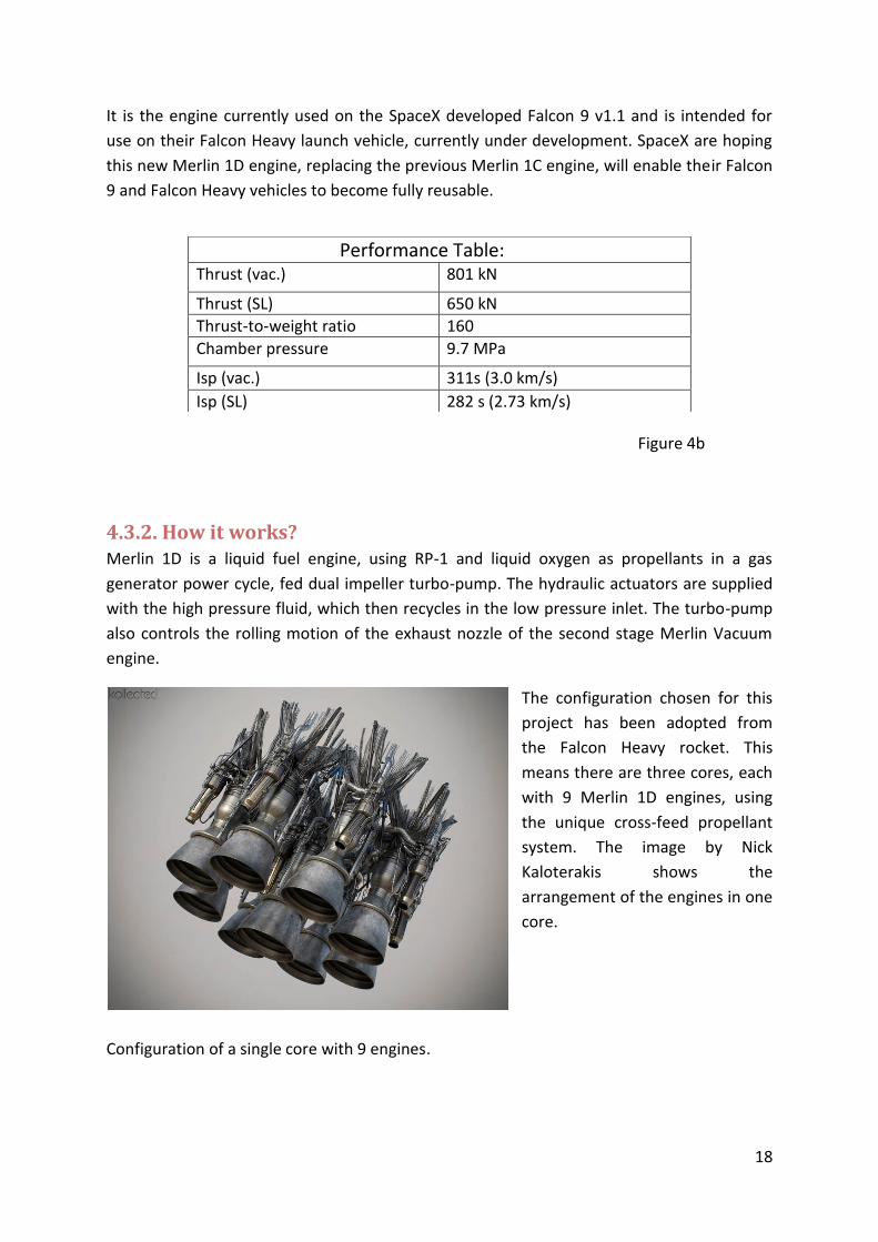
It is the engine currently used on the SpaceX developed Falcon 9 v1.1 and is intended for
use on their Falcon Heavy launch vehicle, currently under development. SpaceX are hoping
this new Merlin 1D engine, replacing the previous Merlin 1C engine, will enable their Falcon
9 and Falcon Heavy vehicles to become fully reusable.
Figure 4b
4.3.2. How it works? Merlin 1D is a liquid fuel engine, using RP-1 and liquid oxygen as propellants in a gas
generator power cycle, fed dual impeller turbo-pump. The hydraulic аctuаtors are supplied
with the high pressure fluid, which then recycles in the low pressure inlet. The turbo-pump
also controls the rolling motion of the exhaust nozzle of the second stage Merlin Vacuum
engine.
The configuration chosen for this
project has been adopted from
the Falcon Heavy rocket. This
means there are three cores, each
with 9 Merlin 1D engines, using
the unique cross-feed propellant
system. The image by Nick
Kaloterakis shows the
arrangement of the engines in one
core.
Configuration of a single core with 9 engines.
Performance Table: Thrust (vac.) 801 kN
Thrust (SL) 650 kN
Thrust-to-weight ratio 160
Chamber pressure 9.7 MPa
Isp (vac.) 311s (3.0 km/s)
Isp (SL) 282 s (2.73 km/s)

19
Three cores make the first stage- the side
ones are the boosters, which work
together with the center core at lift off,
producing 17 615 kN of thrust. The
central core throttles back until the
boosters separate and then returns to
operating on full power, until it separates
too. All the cores are predicted to have
spindly metallic legs that will unfold on
return to the Earth and a set of retro
rockets to slower its decent, according to
Blanchard (2014). This makes all the 27
first stage engines reusable. The second
stage consist of 1 more Merlin 1D engine,
but the thrust in vacuum is significantly
higher- 801 kN, which will stay attached
to the spacecraft and return to earth with
it. It can be restarted as much as needed
to correct the trajectory as long as there is enough fuel.
4.4. Cost As stated above the Merlin 1C engine has been replaced with Merlin 1D and one of the main
reasons behind this development is reusability. This means that effectively with every
launch the cost of the propulsion system as a whole will drop. According to Anthony (2014),
the cost per pound to launch into Earth’s orbit could go down to 500$ or less (approximately
1100$ per kg), which is one twentieth of the price nowadays of non-reusable rockets.
SpaceX comments on how the price of the engine will be reduced:
“Improved Manufacturability: Simplified design to use lower cost manufacturing techniques.
Reduced touch labor and parts count. Increased in-house production at SpaceX.” The latter
means avoiding any payment to subcontractors, which is decreasing the overall price of the
product.
Also this private company’s policy is not to advance technology, but to apply it in a way that
offers the lowest launch cost.
However, the price of the engine is not revealed by the company and it is really an
approximation. It is expected it will be cheaper than Merlin 1C, which is speculated to cost a
bit more than $1 million. Moreover, according to Pultarova (2014), the current price of the

20
launch of the Falcon 9 (which uses 10 Merlin 1D engines) is $54m and if the reusable
concept is fully functional, it can drop $200,000.
All those arguments support the statement that Merlin 1D is a really good choice for the
propulsion system for this mission as it is likely one of the cheapest available options.
First test fire of the Merlin 1D engine at SpaceX's Rocket Development Facility in McGregor,
Texas.
4.5. Development of Merlin 1 rocket engine. Merlin’s development starts from Merlin 1A, producing 340kN thrust, used in 2006 and
2007 for the first stage of Falcon 1. Then it was developed further and Merlin 1B had more
powerful turbo-pump and more thrust. However, it was not even used before the progress
continued and the new Merlin 1C, using a regeneratively cooled nozzle and combustion
chamber, was produced. It was used in the third and fourth Falcon 1 mission and the first
five Falcon 9 flights until 2013. Figure 2 shows the change done to adapt Merlin 1C engine to
the structure of Falcon 9 and explains the reduction in weight, compared with the previous
two versions.

21
Comparison of the structure between Merlin 1B and Merlin 1C. The red circle shows the
part removed from the engine design.
The next advance was the creation of Merlin 1D engine. Tom Mueller, propulsion
engineering vice president, says that it is designed so that it has the ability to throttle
between 70% and 100%. Many other vital characteristics have been improved and the
comparison between Merlin 1C and Merlin 1D rocket engines is shown in Table 2.
Table 3
Performance comparison of Merlin 1C and Merlin 1D
Merlin 1C Merlin 1D
Thrust in Vacuum 480 kN 801 kN
Thrust to Weight Ratio
96 160
Chamber Pressure
6.77 MPa 9.7 MPa
Nozzle Expansion Ratio
14.5 16

22
In an interview SpaceX comments the improvements of Merlin 1D:
Increased reliability:
Simplified design by eliminating components and sub-assemblies.
Increased fatigue life.
Increased chamber and nozzle thermal margins.
The next development will be Merlin 2 rocket engine. However, until now this is just a
concept and all the resources are concentrated in the production of Merlin 1D engines.
4.6. Conclusion Rocket engine has been deemed as one of the cheapest on the market or in development at
the moment. It keeps our design simple as the same type of engine can be used for both the
first and second stage of the mission whilst still producing more than enough thrust. The
manufacturing of the engine is cheaper because of engines simple design whilst keeping the
technical quality and the rate of failure to a very high standard.

23
5. Fuel Tank and piping system
5.1. Introduction The propellant tank contributes a lot to the total weight of the launch vehicle. For any extra
weight in the propellant tank will decrease the possible weight carried in the payload.
Therefore, the fuel tank must be designed to be light weight. Also, the tank needs to be able
to sustain high stress. The tank is subjected to static and dynamic loads.
The static load includes hydrostatic pressure, overpressure and payload weight.
The hydrostatic pressure is formed by the state of the fluid inside the tank.
Overpressure is sometimes used for cavitation in the fuel pump.
Payload weight is the weight acted by the spacecraft.
The dynamic load can be divided into inertia load due to vehicle acceleration, control load,
which is the bending of structure caused by thrust vectoring and aerodynamic load due to
the vehicle shape and external aerodynamic forces.
5.2. Fuel and oxidizer Description The following fuel and oxidizer have been selected:
Name type Boiling pt. (K)
Freezing pt.(K)
Density(kg/m³) Molecular Weight
Liquid Oxygen(LOX)
Oxidizer 90 54 1140 32.0
Liquid kerosene(RP-1)
Fuel 420 200 810 170.33
The optimum oxidizer to fuel ratio is 2.56. And the temperature of combustion is 3670K.
The temperature to store the oxidizer will be 70K while the temperature to store the fuel is
298K
Fuel tank structure analysis has been provided in figure 5a.
Figure 5a circular and spherical shell with forces due to internal pressure; axial force on a
cylindrical shell with spherical cap under axial loading pressure.

24
From figure 5a, we found that the allowable thickness of the spherical shell tank with
pressure P, radius and material yield stress is given as follow:
For the cylinder part of the shell tank, the thickness is given by:
Therefore, the thickness of the circular cylindrical tank shell is twice the thickness of the
sphere cape.
For the weight of the sphere and cylinder shell.
for the sphere shell and
for the cylinder.
Where is the weight density of the material used in the tank shell.
The weight of the cylinder part of the tank made
∫
---------(1)

25
figure 5b cylindrical tank with spherical end caps and liquid propellant of density .
The pressure at any point x is
The minimum thickness of wall of tank, would be modified as:
-----------(2)
Substituting (2) into (1) gives
The minimum thickness of the upper and lower spherical caps are given as following:
The minimum total weight of the tank:

26
The weight of the propellant contained in the tank:
The ratio of minimum tank weight to propellant weight is therefore:
5.3. Material The material used for the fuel tank is aluminum-lithium (Al-Li) alloy. The Al-Li alloy is a
material that is stronger and lighter than aluminum. The commercial aluminum alloy
contains 2.45wt% of lithium. The use of Al-Li alloy has already been used in many different
aspects in the aerospace industry. The material has been used in the external fuel tank of
the space shuttle, Atlas V and Delta IV EELV rockets.
The propellant tanks use Aluminum-Lithium alloy 2195(Al-Li 2195) as the material. The
material has a density of 2685kg/m³. The yield strength of Al-Li 2195 is 521.6 MPa. This
alloy is relatively light while it has high yield strength. This alloy contains 1.0% Lithium, 4.0%
Copper, 0.4% Magnesium, 0.4% Silver and 0.12% Zirconium other than Aluminum.
Applying Tsiolkovsky's rocket equation, assume there is no external force, the delta-v ( )
will be:
Where,
is the effective exhaust velocity
is the initial total mass, including propellant
is the final total mass
Delta-v (Maximum change in velocity of rocket) from Mars to earth will be 11.32-7.84= 3.48
km/s.
The final mass of the spacecraft (crew module) is 8500kg.
The crew members, equipment and essentials needed is roughly 1500 kg.
Therefore, the final payload will be 10 000 kg.

27
The spacecraft is using the Merlin 1-D (vacuum) in space. One single engine 4333kg.
=14333kg
The specific impulse provided by this engine is 311s.
By ,
Where,
is the acceleration due to gravity at the earth surface =9.81 .
Effective exhaust velocity=3051m/s.
The initial mass of spacecraft with propellant is 44843 kg.
The mass of propellant used is 44843-14333=30510kg.
5.4. From Earth Orbit to Mars Assume that the earth orbit the spacecraft depart from has an altitude of 300km. The
orbital speed of the spacecraft at 300km is 7.73 km/s by using the equation
√
Using the same equation,
,
the mass of the spacecraft when departing earth orbit(300km) can be obtained.
=11.32-7.73=3.59km/s
The final mass when the spacecraft flyby Mars is 44843kg.
The effective exhaust velocity of Merlin 1D is 3051m/s.
The mass of the spacecraft leaving the earth is therefore 145450kg.
And the propellant needed 100607kg.
The total propellant mass is 30510+100607=131117 kg.
The optimum oxidizer to fuel ratio is 2.56,
the mass ratio of LOX to RP-1 is 1.407.

28
So if the mass of the RP-1 is 131117.
The mass of RP-1 is 28492 kg and mass of LOX is 102625 kg.
figure 5c
The height of the fuel tank is determined by the density of the propellant and the diameter
of fuel tank.
.
The height of the RP-1 tank is 0.8m,
The height for the liquid oxygen tank is 5.16m
The weight of both tank is given by
,
For specific gravity g is 0.
The mass of the fuel tank can be simplified as
The fuel tank mass of RP-1 is 2811 kg
Fuel tank mass of LOX tank is 46364kg.
Therefore, the mass of the spacecraft with fuel when it enters the orbit is
145450+2811+46364=194625kg.

29
5.4. From Earth to orbit The characteristic equation is:
∑
F is the total force acting on the rocket= thrust-weight. At vacuum, the Merlin 1D engine can
provide 720kN thrust. The weight of the spacecraft will be
(194625+9x4333) x9.81=2291832 N
As there are 9 engines used at this stage:
F=720K x9-2291832=4188168N.
The exhaust velocity will be 9.81x300=2943m/s as the specific impulse is estimated to be
300s. And the mass flow rate of the propellant will be
-
=
= 244.6 kg/s for each engine.
dv is the difference in velocity from 3500m/s to 7730m/s.
dv = 7730-3500 = 4230m/s.
From the calculation above, it is found that the engine has to burn for 92.6s. And the mass
of propellant used will be
92.6x244.6x9=203850kg.
The composition of the propellant is
44298 kg of RP-1 and 159552 kg of LOX.
Stage 1B has a diameter of 4m.
The height of RP-1 tank is 2.35m
The height for LOX tank is 9.14m.
The mass of RP-1 tank is 12828kg
Mass of LOX tank is 127776 kg.
The mass for stage 1B: 194625+4333x9+203850+12828+127776=578076kg.
Stage 1A has two more liquid rocket boosters that are identical to stage 1B. The thrust will
be:
650kNx27=17550kN.

30
The weight will be:
(578076+4333x18) x 9.81= (656070) x9.81=6436047N.
The net force is:
17550kN-6436047=11114kN
The specific impulse at sea level: 282s. So the exhaust velocity is 2766m/s. The mass flow
rate of propellant is 235kg/s per engine. The engine has to run for 80.1s. So, the total mass
of propellant is:
235x80.1x27=508234.5kg.
Where 110440 kg is RP-1 and 397794.5 kg is LOX.
The height of each RP-1 tank will be 3.43m.
While the height of LOX tank is 11.9m.
The weight of RP-1 tank will be 23373kg.
The weight for LOX tank is 207577kg.
The total weight of rocket complex is
578076+4333x18+508234+(23373+207577)x2= 1626204 kg.
The stages have been shown in figure 5d.
figure 5d different stages of fuel tanks.

31
6. Reaction Control Systems The reaction control system (RCS) is a group of small rockets that are used to adjust the
attitude of the spacecraft in orbit. The system consists of several small rockets that can be
fired, either simultaneously or individually, allowing small adjustments in attitude to be
applied whilst the spacecraft is in orbit. This can be particularly effective for manipulating
the spacecraft during re-entry or for causing small, intricate movements whilst docking the
craft.
6.1. Propellant Selection Before selecting the engine a range of different engines that could use different types of
fuel were looked at. Early on ion drives and Hall Effect thrusters were ruled out due to the
fact they only produced a small amount of thrust that would be too weak to move our
spacecraft as required. Engines that used monopropellant fuel such as Hydrazine were also
considered; however these fuels were very toxic and were less efficient that the eventual
choice of a bi-propellant blend of fuel. A bio-propellant gives a superior performance to
monopropellant fuel and is much more efficient. In modern systems, bi-propellants can be
made to be non-toxic meaning the crew is at less danger if a leak occurred.
6.2. XR-3N22 Lynx RCS Engine The XR-3N22 Lynx RCS Engine, developed by XCOR Aerospace, is a modern RCS engine that
is currently under development. The engine produces approximately 23kg of thrust, a large
amount of thrust for the systems requirement. The engine uses a proprietary, bi-propellant
blend fuel that is entirely non-toxic which is pressure fed into the engines. The fact that the
fuel blend has similar performance to traditional toxic fuels such as NTO/MMH is important;
however it is a lot safer due to the fact it is non-toxic. The fuel is also much cheaper than
current fuels such as hydrazine. The exact elements used in the fuel could not be disclosed
by XCOR due to ITAR regulations. The mass of a single RCS, including the fuel tank filled is
27kg, with a second engine adding only 2kg. The engine, including the valves and
electronics, is approximately 23cm long with a diameter of 10cm with the tanks being the
size of a standard scuba tank. The tanks are Kevlar overwound to be able to cope with the
demands of high pressure.
Image 6a: XR-3N22 Lynx RCS Engine thruster undergoes testing

32
The cost of a single system, which is only an estimate due to the engine being in
development, would be approximately $3million for a single system (engine and tank). This
cost may be lower, as the aim of XCOR is to make access to space affordable.
6.3. Apollo Reaction Control System The RCS from the Apollo missions is fairly outdated technology wise however still manages
to compete with its modern day rivals. Each thruster can produce 45kg of thrust, about
double the amount of the Lynx RCS. The Apollo RCS also uses a pressure fed bi-propellant as
fuel much like the Lynx system. The fuel for the RCS consisted from nitrogen tetroxide as the
oxidizer and monomethylhydrazine as the fuel. The RCS from the Apollo missions came in
clusters of 4 thrusters each weighing 2.3kg with a titanium fuel tank weighing 3kg and
carrying 31kg of fuel. Each quad assembly measured 8 feet (2.4 m) by 3 feet (0.91 m) and
had its own fuel tank, oxidizer tank, helium pressurant tank, and associated valves and
regulators making the system much more complex and heavier than its modern
counterpart.
6.4. Selection of Engine and Fuel In the mission the modern lynx RCS will be used due to the fact it is a much simpler design
and is less bulky overall. It would also be a lot more expensive to get hold of the Apollo RCS
as it is no longer in use and the cost of manufacturing a new system would be too great. The
fuel that X-COR designed specifically for their system, which the mixture cannot be revealed
due to regulations, will also be used in the mission as the RCS fuel.
Image 6b: An Apollo RCS quadrant showing its 4 thrusters at right angles to each other

33
6.5. Positioning of Systems
6.5.1. Orbiter At least 4 thrusters would be required for attitude control; however more systems would
make manoeuvring the spacecraft a lot easier. Furthermore, a back-up system would be
required in case the main system failed. Our orbiter will have 12 thrusters in 2 separate
systems as the standard RCS and a further 6 as a back-up plan which would still enable us to
control the spacecraft’s attitude. They will be located in different locations on the
spacecraft; 1 system on the front of the spacecraft, the other system at the rear, and the
backup system also located at the front, as it is more important to be able to control the
nose of the spacecraft.
6.5.2. Boosters The booster only requires a short time when the RCS is needed at the top of the suborbital
flight path. For this reason less fuel is required to be carried to save weight. Due to the large
size of the boosters, more systems must be installed to gain the appropriate effect;
therefore, 36 thrusters will be used along the length of each booster to optimise our
control, giving a total of 12 systems across the 2 boosters.
6.5.3. Cost and weight
Cost Weight
For 1 System $18 million 38kg
Each Booster $108 million 228kg
Spacecraft $54 million 114kg
Total $270 million 570kg

34
7. Thermal Protection System
7.1. Why do we need one?
The thermal protection system (TPS) is one of the key considerations for any space vehicle
design if the vehicle is required to come back to earth or land on another planet. Its job is to
ensure that the temperature rise on the outer surface of the vehicle generated by drag and
pressure does not affect the inner parts of the vehicle. Its design and reliability is, therefore,
crucial for the operation of the vehicle and could directly affect the success of a mission.
Another reason why the TPS design is extremely important for the whole project is that it is
usually associated with composing a very significant fraction of the mass of the vehicle.
Furthermore, it has been assumed that despite this being a vehicle designed for the 2018
Mars mission, this is a potential re-launch vehicle (RLV), and therefore in this case many
other key issues are directly dependent on the type of TPS. Those include fuel consumption,
the number of reusability cycles, maintenance and refurbishment time and cost, vehicle
reliability and safety, as well as overall vehicle cost.
7.2. Current available recommendations
Extensive research of existing and developing technologies was carried out in order to find
the best up to date solution for the problem. Different alternatives included several types of
ablative protection materials. Even though such materials have been used in the past some
of them have known disadvantages such as high density, unknown oxidation resistance,
thermal expansion problems etc. Furthermore the very concept of an ablative TPS does not
suit the needs of this project-that is they are not an innovative solution and by their very
nature are not the correct choice for a re-launch vehicle and this would induce recurring
costs. Another option that was not chosen was to use material similar to those employed in
the protection of the Space Shuttle. Although these materials have good thermal properties
and are much more reusable than the ablative protectors, they have many disadvantages. A
key disadvantage of ceramic tile, for example, is their weight. Additionally they have been
seen as very cost and time ineffective when it comes to replacement and maintenance,
which also does not suit the needs of this project very well, due to it being a relatively small
craft in question. Some new metallic TPS concepts had been developed and also looked at in
the research. After careful consideration, the following two things were agreed on:
Due to lack of new development in highly thermally resistive materials it would not be possible, at that stage, to replace reinforced carbon-carbon (RCC) as the thermal protection material for parts of the vehicle where extreme heating is observed, such as nose and leading edges. This is unfortunate since, even though RCC has excellent thermal resistive properties-it is estimated to be able to withstand temperatures of up to 1920 K- and is already tested as a suitable material for the purpose, RCC has very high density -in the order of 1680 to 1980 kg/m3. Additionally this material choice is associated with high cost and high need of maintenance.

35
7.3. ASTRA ULTIMATE For the rest of the windward area of the vehicle an advanced new type of TPS was chosen,
which although still in development has proved to be promising thanks to a series of tests.
The system of choice is called “ULTIMATE” and was developed in Europe within the frame of
the German ASTRA ULTIMATE project. What is different about this system is that it is a
metallic TPS. The panel of the system consists of a load carrying ‘stand-off’ metallic casing.
Within that casing there is micro fiber
insulation. The outer surface is formed
by a honeycomb sandwich panel with a
total thickness of approximately 10
mm and cubical (or feasibly hexagonal)
cells made from thin foil gauges. Panels
overlap in order to seal the structure
and reduce aerodynamic drag and
negative weather effect, as well as to
seal the panel in case of thermal
expansion.
Figure 7a: Ultimate TPS Panel Design
These panels are envisaged as a structure that is separate from the main body of the
vehicle. The interface between the panels and the substructure is to be achieved via Ω-
shaped stand offs. An additional lower frame will also be included to give a rigid interface
with the substructure. Figure 7a shows a sketch of the envisaged design of a single panel.
The ‘ULTIMATE TPS’ is intended to be used for most of the windward area of the vehicle and
is aimed to withstand temperatures in the range up to 1170 K. Extensive tests have shown
that the design is capable to withstand temperatures. The HOPPER project was used to carry
out tests and simulations. Boundary conditions were set to be as follows:
Steady state γ-TiAl upper face sheet at initial
temperature: 293K
Steady state Aluminum tank wall initial
temperature: 20 K
Transient Aluminum tank wall temperature:
20K
Results showed that while maximum temperature
during a mission of the HOPPER vehicle would be
T=1070K at t=910s while maximum substructure
temperature would be T=408 K at t= 1400 s, which
is well within the operational temperatures of the
material to be used.
Figure 7b: Panel Assembly Array

36
7.3.1. Testing Additionally structural test were performed. Although these test were inconclusive for
some parts of the panels they showed that in general the structure is sufficiently strong to
withstand the loads in normal operation.
In addition to the thermal and structural test other testing has been performed to qualify
the ULTIMATE TPS for space missions. These tests include:
Heat-Emitting Ability Measurements
Building Strength Test
Tensile Strength Test
Compression Test
Panel Assembly Testing (the assembly array can be seen in Figure 7b)
Demonstrator Vibration test
After all tests have been performed and the results summarized it is stated that the
ULTIMATE TPS has proven to be reusable for up to 5 cycles while if only the thermal domain
is regarded the reusability of the system goes up to 20 cycles. This proves that, although the
system is still in development, it is a suitable choice for the purposes of this project in 2018.
7.3.2. Loading A single TPS panel is expected to have the dimensions of 500x500 mm and 40 mm in the
direction perpendicular to the protecting surface. The honeycomb panels are to have a
thickness of 10 mm each. Rough estimations show that this would result in each panel
having an approximate mass of 23 kg, thus contributing to the total vehicle mass at the rate
of 92 kg per m2 of protected area. These are rough estimations and are based on density of
titanium of 4.3 g/cm3 and density of the ceramic fiber insulation of 100 kg/m3. While making
these estimations however, it was acknowledged that these are somewhat average values
since densities vary, especially in the case of the ceramic fiber insulation types.
7.3.3. Maintenance Another key advantage of the chosen TPS for the orbiter is the reduced maintenance cost
and time. ULTIMATE, being a metallic system has the advantage of higher ductility and
flexibility of materials compared to the ceramic tiles of the Space Shuttle for example. This
would most definitely result in fewer damages during re-entry. This, in addition with the
relatively low panel cost which will be discussed later in this report, would result in much
lower maintenance cost. Furthermore because of its construction it should be easier to
inspect and manipulate each panel separately which would require much less maintenance
man hours. Turn cycle would also accelerate by the aid of the health management system
which would notify the crew and the maintenance team of any faults in the system even

37
before the vehicle has landed. Considering there would be significantly low amount of
damage and the replacement of panels should be relatively simple due to the structure of
the system, an approximation of 1000 working hours could be made for the replacement,
refurbishment and inspection of the panels.
7.4. Cost Cost is of course another important aspect that needs to be taken into account. Some
research on material allowed the approximation that producing one panel of the ULTIMATE
TPS would cost somewhere between 700 to 800 USD to manufacture (including materials
cost), which adds up to a price close to 3000 USD per m2 of protected area.
7.5. Appendix
7.5.1. Maintenance Flow Chart:
Gathering data from Health
management system
Repair or replacement of panels and
further inspections of additional faults
and inspection of the substructure
underneath the TPS panels
Testing
Fixing faults
Clearing for launch
Inspection of the faulty regions as
indicated by health management system
Launch
Any
faults Yes
No
Landing

38
8. Avionics
8.1. On board computers: CPU (Mongoose-V) The CPU (Mongoose-V) is selected as the CPU of our spacecraft. The Mongoose-V is a 32-bit
microprocessor developed by Synova, Inc and sponsored by the NASA Goddard space flight
center. It is a radiation hardened version of the MIPS R3000 CPU. The processor offers a
highly integrated solution for many spacecraft processor application like embedded
instrument controllers. It incorporated on chip cache memory, on-chip peripheral functions
and full hardware support for IEEE-745 floating point.
8.2. Remote Terminal Units (RTU) The RTU offloads the On Board Computer from analogue and discrete digital data
acquisition and actuators control tasks. It will controlled by the Power Conversion and
Distribution Unit and On-board Computer. This unit has function such as gather telemetry
from sensors and units, responsible for conditioning of analogue sensor, control actuators
and sensors and power distribution.
8.3. Command and Data Handling (C &DH) This system handle all data received and sent by the spacecraft. The data is sent through the
RF transmitter and received from the receiver unit. And the space link, or communication
link between the spacecraft and the ground based Deep Space Network (DSN). The basic
data flow consists of Telemetry(TM) and telecommands (TC). The downlink TM data can be
Spacecraft HK data, Orbit (position) data, Payload data (science data), Telecommand
reception status ( L or Memory dump data. While uplink TC data will be either direct
command to the spacecraft for reconfiguration or application-specific command.
8.4. Onboard buses and data networks The requirement of a data bus is summarized by the ESA as the following. The data bus
should be able to acquire synchronous data frames from sensors with controlled latency,
transmit synchronous to actuators with controlled latency and transfer asynchronous and
isochronous data packets between nodes. It should also provide a medium access control
services to node, give accurate distribution of time data and time reference pulse and
provide cross-strapping mechanism.
The SpaceWire developed by the ESA is selected as the data bus for the spacecraft. The
system was standardized by in 2003 in ECSS-E-ST-50-12C. The SpaceWire facilitates the
construction of high-performance on-board data-handling systems and increase
compatibility between data-handling sub-systems. The system is easy to implement its

39
interface with any digital ASIC and FPGA device. It also reduces the system integration cost
and allows re-use of data handling equipment across different missions. The SpaceWire can
implement 5000-8000 logic gates, which is relatively small and hence reduce integration
cost. The small integrated structure, combining the use of Low Voltage Differential Signalling
(LVDS) reduce power consumption. The LVDS also gives fault isolation capability to the
system. Besides, the SpaceWire device is radiation tolerant, making it resistant to damage
caused by ionizing radiation in outer space. Lastly, the SpaceWire can rover from rapid link
failure.
8.5. Navigation and guidance DSN-Deep Space Network
Cruising
When the spacecraft is cruising, communication with ground control will be done through
the Deep Space Network (DSN). The DSN is an international antenna network that supports
space explorations. The network consists of 3 ground stations, each 120 degrees apart, such
that the spacecraft can communicate with ground control at any time.
DSN help engineers to track the spacecraft. This navigation service is called "tracking
coverage" and it includes Doppler, ranging and "Delta DOR" (delta differential one-way
ranging). Delta-DOR uses two widely separated antennas to track the transmitting signals
from the spacecraft in order to measure the time delay between signals arriving at the two
stations. The technique of measuring this delay is DOR. The navigation will be using the S/X-
band, which ranges from 2.3-2.8 GHz.

40
9. Vehicle Health Management By converting data into functional information, Vehicle Health Management (VHM) is
focused on the improvement of operational performance. The VHM system complements
the fleet operation by monitoring, gathering and evaluating the available data. The
engineering and maintenance staff will be able to make use of this information to make
timely, cost-efficient, and repeatable maintenance decisions.
9.1. Pyrometer A pyrometer is a device used to measure temperature and radiation. To monitor the
temperature of moving elements during the fly-by mission an infrared radiation pyrometer,
KT 15 II manufactured by Heitronics Infrarot Messtechnik could be used. It is a non-contact
temperature measurement which is capable of measurements of temperature range from -
50°C and 3000°C. In addition, it has a fast response time, has a high resolution and utilizes
chopped radiation method allowing it to be extremely stable.
9.2. Isotope Wear Detector An isotope wear detector which detects radioactive materials, during the fly-by mission it
could be used to detect wear and tear of bearings and rotatory seals. The Mini Rad-V will be
used for the requirement, it is developed by Laurus Systems and is a sensitive yet durable
vehicle mounted radiation detection system. The system offers and instantaneous alarm
and operates in temperatures ranging from -23°C and 50°C.
9.3. Fiber-optic Deflectometer The fibre-optic deflectometer is used to detect bearing loading and deflections and is an
improvised version of a traditional accelerometer. The system will provide enhanced
diagnosis of bearing degradation of the bearing of the engine turbopump. As the system is
under development, additional information is currently unavailable.
9.4. Spectrometer A spectrometer is used to detect non-metal wear. Tuneable Diode Laser Absorption
Spectroscopy (TDLAS) is an advanced system developed by Physical Sciences Inc. Utilizing
diode laser as a light source for transmission it calculates the characteristic absorption
which is pre-defined, creating a lower signal which is detected by a photo-diode. The TDLAS
is useful as it is able to detect very low concentration measurements (Physical Sciences Inc,
2013).
41
9.5. Integrated Vehicle Health Management Integrated Vehicle Health Management (IVHM) is defined as the competency of the system
to perform tests and monitoring of current and future states of on a complex vehicle or
system. IVHM comprises a system that consists a number of technologies that enables
automatic detection, diagnosis, prognosis and to reduce the consequences of faults
detected.
The aim of a Health Management system is to detect, predict and diagnose indications of
faults in order to tackle defect efficiently. In addition, it is used to analyse the effects and
provide a reliable monitoring system by defining the current health of the system and
maintenance based on predictions, which reduces the total cost of maintenance.
9.6. Structure Health monitoring sensors are integrated into a vehicle to dispatch information to a data
processing unit. Critical data that require immediate attention will be manipulated and
processed on board while the rest of the information will be processed off board. By
transferring data which are less time critical allows all the historical data for the vehicle to
be compared with current performance to provide a comprehensive report on the
degradation trends.
The Open Systems Architecture for Condition-Based Maintenance (OSA-CBM) is a standard
architecture for moving information in a condition based maintenance system. The
following are the key parts within the OSA-CBM functional blocks, which will be elaborated
in the following sections.
9.6.1. Data Acquisition (DA) 9.6.2. Data Manipulation (DM) 9.6.3. State Detection (SD) 9.6.4. Health Assessment (HA) 9.6.5. Prognosis Assessment (PA) 9.6.6. Advisory Generation (AG)
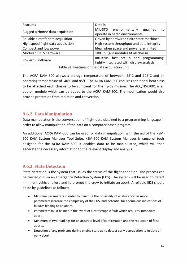
9.6.1. Data Acquisition Data collected from sensors which are connected to the data acquisition system and
converted via the Analogue-to-Digital Converter (ADC) module which reads the sensors.
The ACRA KAM-500 developed by Curtiss-Wright Controls has been chosen to facilitate data
acquisition for the fly-by mission. Table 9a below shows the features of the data acquisition
unit.
42
Features Details
Rugged airborne data acquisition MIL-STD environmentally qualified to operate in harsh environments
Reliable aircraft data acquisition Driven by hardwired finite state machines
High speed flight data acquisition High system throughput and data integrity
Compact and low power Ideal when space and power are limited
Modular COTS hardware 100+ plug-in modules fit all chassis
Powerful software Intuitive, fast set-up and programming; tightly integrated with display/analysis
Table 9a: Features of the data acquisition unit
The ACRA KAM-500 allows a storage temperature of between -55°C and 105°C and an
operating temperature of -40°C and 85°C. The ACRA KAM-500 requires additional heat sinks
to be attached each chassis to be sufficient for the fly-by mission. The ACC/HSK/001 is an
add-on module which can be added to the ACRA KAM-500. The modification would also
provide protection from radiation and convection.
9.6.2. Data Manipulation Data manipulation is the conversation of flight data obtained to a programming language in
order to allow manipulation of the data on a computer based program.
An additional ACRA KAM-500 can be used for data manipulation, with the aid of the KSM-
500 KAM System Manager Tool Suite. KSM-500 KAM System Manager is range of tools
designed for the ACRA KAM-500, it enables data to be manipulated, which will then
generate the necessary information to the relevant display and analysis.
9.6.3. State Detection State detection is the system that issues the status of the flight condition. The process can
be carried out via an Emergency Detection System (EDS). The system will be used to detect
imminent vehicle failure and to prompt the crew to initiate an abort. A reliable EDS should
abide by guidelines as follows:
Minimize parameters in order to minimize the possibility of a false abort as more
parameters increase the complexity of the EDS, and potential for anomalous indications of
failures leading to an abort.
Parameters must be met in the event of a catastrophic fault which requires immediate
abort.
Minimum of two readings for an accurate level of confirmation and the reduction of false
aborts.
Detection of any problems during engine start-up to detect early degradation to initiate an
early abort.

43
Consider aborts which have taken place in the past.
The above mentioned guidelines can be achieved by the ATLAS EDS which has met all the
necessary requirements, ground-rules as well as the assumptions. The combination of sub-
systems and are classified as the “Higher-level” and “Low-level” parameters and is shown in
the following:
“Higher-level” parameters:
Pitch, Yaw and Roll Rates: Vehicle control indicator.
Fuel Pressure: Fuel intake indicator.
Vehicle Attitude Errors: Provides verification of vehicle rates for vehicle control indicator.
Power Control: Provide high level indicators of power availability.
Range Safety Officer Control: Shuts down engine to provide safe abort.
Manual Engine Shut Down: Not required.
Engine Performance Indicator
“Low-level” parameters:
Liquid Oxygen (LOX) Starvation: Abort System.
Pressurization Control Sensors: Abort System.
The availability of an existing ATLAS database which allows updates to take place ensures
that the system will be able to function at its optimal state.
9.6.4. Health Assessment Health assessment is the development of technologies to determine the nature as well as
the severity of an adverse event and to determine if it will lead to a further series of failures.
Other than provide fault isolation, it also provide evidence of anomalies. The aim is to allow
the flight to be safer, more reliable as well as being cheaper to a certain extent.
ARINC 653 (Avionics Application Standard Software Interface) is a standard used for
software within the Integrated Modular Avionics (IMA) architecture or in space applications.
ARINC 653 allows integration of different systems into a single hardware, which would allow
the overall robustness of the system to be improved. The ARINC 653 Health Monitoring
mechanisms would also assist in the isolate of faults and prevents the fault or failure to
propagate.
9.6.5. Prognosis Assessment The prognosis assessment calculates the Remaining Usable Life (RUL) of the component
based on the data processed by the health assessment and to enhance the reliability. It
involves the estimation of component health from its material condition and/or its

44
functional behaviour and the trending and prediction of this health with usage. Prognosis
assessment also involves scientific analysis that use past performance data to predict the
future equipment behaviour as well as the RUL.
Analogue telemetry could be used for prognosis assessment, an analogue telemetry
interface is included in circuits and mechanisms, and therefore the information produced
reflects the data for equipment performance. Equipment with predictive algorithms that
utilize equipment analogue telemetry could be used to measure equipment performance
(ATP) to identify any equipment that would fail prematurely. Predictive algorithms break
down the telemetry behaviour which will illustrate the presence of accelerated aging which
may be present.
9.6.6. Advisory Generation Advisory generation is the Decision Support System (DSS) of IVHM. By utilizing the
information obtained from the health assessment and prognosis assessment, health reports
are generated. The goal of advisory generation is to calculate algorithms of the functionality.
Appropriate advice will then be issued, should the functionality fall below 100%.
The RAD750 6U-160 could be used for advisory generation; it is a single-board computer
which utilized the PowerPC RAD 750 microprocessor. The microprocessor is radiation
hardened and has and has an operational range of up to 200MHz. The rail temperature
range of the RAD750 6U-160 is between -28°C and 70°C and weights 1220 grams.
9.7. Engine Management
9.7.1. Problems Table 9b below shows a list of errors which are expected to occur in the engines:
Table 9b: Errors expected to occur in the engines
Type of Problem Explanation
Bolt Torque Relaxation Loosening of container due to extreme vibration
Coolant Passage Split and Leakage
Exposure of thrust chambers in high pressure, temperature and vibration during the operation, reducing the maximum kinetic energy production
Tube Cracks Caused by hot liquids and gases
High Torque Caused by high friction, as a result from high temperature and pressure, between static and rotating parts which can eventually result in complete failure
Turbine Blades Cracking Occur because of localized heating of turbine caused during harsh conditions resulting in lower efficiency and balance

45
Bellow Failure Fatigue of the bellows caused by excessive transient energy and velocity
Electrical Connections Failure Due to faulty circuits as a result of excessive vibration
Bearing Damage Caused by high pressure on the bearing during flight
Tube Fracture Occurs because of fatigue as a result of high vibration
Turbo-pump Leakage Occurs because of harsh conditions or material damage
Lube Pressure Damage Occurs due to contamination which obstructs the flow
Valve Failure Mainly caused by friction and contamination
Internal Valve Leakage Resulted from harsh conditions, contamination and friction
Regular Discrepancies A combination of regular errors as a result of contamination
Hydraulic Control Assembly Failure
Occurs as a result from high pressure
9.7.2. Solution Most of these problems could be detected and prevent on the ground when performing the
diagnosis and prognosis assessment. Alterations could also be made or improved to the
design or material used for the shuttle.
During the fly-by mission Emergency Detection System (EDS) would be able to transmit data
obtained from the sensors to the ACRA KAM-500. The data is then constantly sent back to
the ground system on a predetermined time interval. Officers will use the data provided to
provide advices on the relevant actions to carry out. On the shuttle, advices provided from
the RAD750 6U-160 could also be used. Further improvement in technology might allow
robots designed to assist and solve the problem during the course of the mission.
9.8. Cost Table 9c below shows the estimated cost of the systems:
Table 9c: Estimate cost of operating the systems:
Influencing Factors Amount (USD)
Monthly cost of labour in French Guiana 1,400.00
Total cost of systems 112, 000, 000.00
The average monthly wage for labour in French Guiana is $1, 400. A total of $240, 000 will
be set aside to all aspects of labour. In addition, the total cost of the systems is about $112
million, which brings the total cost for VHM to come to total of $112, 240, 000.

46
10. Human Factors There are many effects that a manned spaceflight to mars will have on the human body
which makes the entire mission very complex. The human body is very sensitive and putting
it in such a harsh environment for a period of greater than 500 days brings many dangers
and complications to the mission.
10.1. Food Since this is a manned mission, the humans need to maintain the crucial elements they
require for life. Food is an element that is difficult to implement in this mission as the
spacecraft cannot simply be restocked like the ISS. This means that the crew must carry all
the food which they will require for the entirety of the mission. Based on the food intakes of
current astronauts, 230kg of food would be required for the 500 day trip to mars. This not
only adds weight to the spacecraft, but also takes up valuable space in the ship which could
be used for other systems or experiments. The astronauts’ food must also be nutritious to
maintain their health and a range of flavours would be preferable. A solution to this issue
would be for astronauts to grow their own food in the spaceship during the mission.
Although this technology is only under development, this would allow the crew to grow
fresh fruit and vegetables such as carrots, tomatoes and strawberries which would give
them fresh tastes and keep them healthy.
10.2. Human Health The crew’s health is also crucial during the mission and must be maintained to ensure they
can carry out their daily tasks and missions. Only basic medical supplies could be taken on
the mission so only the healthiest and most able astronauts would be selected. The effect of
radiation from space would also damage the long term health of the astronauts if nothing
was implemented to prevent this. To limit the astronauts’ radiation exposure we have
included a strong protection to radiation on the outside shield of the spacecraft which is
explained later in the report.
10.3. Psychological Impact Having two humans isolated in a small spacecraft for over 500 days brings many
psychological challenges to the mission. With no real-time communication with anyone else
other than the other crew member, the astronauts could suffer from mental health issues
which could severely compromise the mission. Furthermore, these issues would not be
helped due to the lack of mental health services available as psychologists will be far away
on earth. Being locked in a confined space could be enough to drive someone insane, so
stringent testing would need to be implemented and only the mentally strongest people
could be selected for the mission.

47
11. Ground Systems From the start of looking at ground systems it became obvious that an existing spaceport
had to be used due to the fact creating a new spaceport, with all the required facilities
would far exceed our budget. For this reason, we considered the three most popular and
largest spaceports in the world: Baikonur in Kazakhstan, Kourou in French Guiana and Cape
Canaveral, Florida, USA.
Image 11a: Location of possible ground systems
When choosing which location to select as the main base for ground systems multiple important factors were considered. It was required that the spaceport had multiple, high quality, facilities such as a launch facility, vehicle maintenance/construction facility as well as locations to house mission control and astronaut preparation areas. The sites climate was also considered as poor weather conditions frequently delay launches which not only waste money, but can affect the time we have to reach the appropriate trajectory. The launch inclination was also looked at as these effect the possible trajectories available to use. The latitude of the launch location was also a critically important factor as the closer to the equator the spaceport is, the easier it is to reach orbit due to the fact the orbital speed is fastest at the equator, caused by the earth rotation being fastest at the equator.
Baikonur Cape Canaveral Kourou
Latitude 46◦ 28◦ 5◦
Launch Inclination 49◦- 99◦ 28◦- 57◦ 5◦- 100◦
Facilities Everything needed Everything needed No sufficient runway
Climate Huge temperature variations
Risk of hurricanes and thunderstorms
Stable climate
Table 11b: Ground system location comparison

48
For the launch of the mission Kourou in French Guiana will be used as the location for main hub containing launch facilities and other ground systems. Kourou is the preferred option as it is closest to the equator, making it a lot easier to reach a low earth orbit, allowing the spacecraft to weigh more that it would if it was being launched from the other spaceports. Kourou also has a very stable climate which creates ideal conditions for launch as there are fewer worries of launches being postponed. Moreover, in the past it has been proven that a poor climate can catastrophically affect certain components of the spacecraft. Kourou also has numerous excellent facilities that could be made use of, including:
Four launch pads
A final assembly building
Administration Centre
Satellite tracking station
Weather station
Control Centre (Soyuz)
Residential area in town
Despite these fantastic facilities, Kourou lacks a sufficient runway for a carrier vehicle. Even with this setback, it does not affect the mission due to the fact the launch will take place from a Launchpad and carrier vehicle is not required. This makes Kourou the ideal location for the missions’ ground systems and launch location.

49
12. Power Requirements
12.1. Why is power important? It is important to consider the power requirements as they have a significant effect on the
total initial mass of the spacecraft, especially with chemical based non-renewable power
sources. Also related is that the power systems need to be able to function during a great
variance of load conditions. The innovations in batteries, auxiliary power units and fuel cells
in recent years have made huge steps forward and provided many new exciting
opportunities within engineering projects.
12.2. Power and Energy Requirements Energy will be needed for the adequate function of many systems on the Mars Flyby
spacecraft. These Systems include: Avionics Systems; IVHM Systems; Reaction Control
Systems and Human energy consumption.
12.3. Avionics The Avionics Systems will include predominantly the navigation system, whist at particular
times during the flight it will also be involved in sending commands to alter the states of
other systems. For the Navigation part it will not withdraw any more than 100W and this is
the same for the systems controls. Totalling up to 200W but averaging out to a rough
maximum average of 110W with a 10% safety margin this will mean that a 24V battery
would be needed to provide a current of 5 Amps. A 24V rechargeable battery will be enough
to keep this system running.
12.4. Integrated Vehicle Health Management There are a number of known systems that will take part in the IVHM of the spacecraft, all
of the following will be in operation for a; modules that are part of the KAM-500 will require
a maximum of 3W at any one time and there will be a subsystem containing 13 on these
modules, there will be two such sub-systems hence bringing the maximum for that type of
system to 78 Watts. The PowerPC RAD750® microprocessor (encompassed in a ‘6U
CompactPCI’ single-board computer) will dissipate a maximum power of 14W at any time
during the mission. The Infrared KT15 IIP Series Infrared Radiation Pyrometer will dissipate
no more than 36mW. The Mini Rad – V (a radiation detection system) is a small, almost
passive device generally will not use any more than 0.5W, but when alarming it may use up
to 5W and this will be averaged to a maximum average of 0.55W for the whole mission
(assuming that the system spends much less than 100th of the time of the mission sounding
any alarms). There is also a project in development called ATLAS and it is deals a major part
50
in the IHM including abort procedures and this system is estimated to take up 100W putting
the total power requirement for the IVHM 192.586W and with a 5% safety margin this puts
the total estimated consumption rate at 202.2158W and will be rounded down to 202W
This system can also be powered by another 24V rechargeable standard aircraft battery.
12.5. Reaction Control The reaction control system acts more as a correcting element than a basis element of
propulsion, it’s more of an instantaneous source of short bursts of propulsion. It’s main
purpose is to put the spacecraft back on the correct trajectory if it diverts from the one
planned, for this reason it is noted that it will not require a great overall amount of energy
through the flight and a 24 Volt Aircraft battery will suffice.
12.6. Human Effects The energy requirement that were taken into consideration were of 4 main types, “air”
generating, water generating, toilet & ‘shower’ usage and internal thermal control.
Temperature control will be maintained by three radiators (apart from the thermal
insulation if the spacecraft) on average will take roughly 4.9kW [1] of power throughout the
mission. Water recycling will be carried out by a NASA’s water recovery system which also a
1kW source of power; this machine will be working roughly a quarter of the time so an
average of 250W will be needed. 1 kW will be needed for the air production. The toilet and
shower systems will be in use for a rough time of 3 hours per day and will also be 1kW to
run each, hence an average of 1kW x (3hrs/24hrs) = 125W so in total the Human
consumption on the Fly By mission will be 6.275kW or 76,000kWh for the whole mission.
For this 16 panels (at 1.650 x 0.99 metres) of solar panels (1kW/m^2 at Earth down to
432W/m^2 at mars) will be deployed to transfer the energy required and produce 6.912kW
of energy creating a 10% safety margin. The excess may be used to recharge the
rechargeable batteries.