s.p.gopal madabhushi - civil engineering | department of ... · synopsis a new earthquake ......
TRANSCRIPT

PRELIMINARY CENTRIFUGE TESTS USINGTHE STORED ANGULAR MOMENTUM (SAM)
EARTHQUAKE ACTUATOR - PHASE I
S.P.Gopal Madabhushi
CUED/D-SOILSiTR298 (1996)

PRELIMINARY CENTRIFUGE TESTS USINGTHE STORED ANGULAR MOMENTUM (SAM)
EARTHQUAKE ACTUATOR
S P Gopal MadabhushiResearch Fellow (Wolfson College),Cambridge University and
Lecturer, University of Edinburgh, Edinburgh
Synopsis
A new earthquake actuator based on the principle of Stored Angular Momentum(SAM) was developed at Cambridge University. This report concerns itself with theperformance of this new actuator under ‘high g’ centrifuge tests. The concept of theSAM actuator is explained. Results from the initial tests with the SAM actuator arepresented. Based on the results from these initial tests, further improvementsnecessary to the actuator are discussed.
Introduction
Modelling of earthquake events using a geotechnical centrifuge has established as a
powerful technique over the past decade. At Cambridge University many boundary
value problems were studied using a mechanical actuator called the Bumpy Road
actuator, Kutter (1982). Schofield (1980,1981) discusses the scaling laws which relate
the dynamic behaviour of the centrifuge model to the prototype behaviour. Bumpy
Road actuator generates an essentially single frequency ground motion with fixed
duration. This actuator was extremely successful as strong earthquakes could be fired
using this system on payloads of upto 287 kg in a 80g centrifuge test. Using this
system earthquake induced liquefaction problems were studied, for example,
Schofield and Lee (1988) studied the decoupling of sand islands following
liquefaction of the foundation soil, Zeng and Steedman (1993) have investigated the
dynamic behaviour of quay walls with saturated back-tills, Madabhushi and Schofield
(1993) have investigated the behaviour of tower structures on saturated soils subjected
to earthquake perturbations. Large excess pore pressures were observed in the
saturated soils following an earthquake event which resulted in a lowering of the
effective stress. When the magnitude of these pore pressures reaches a value close to
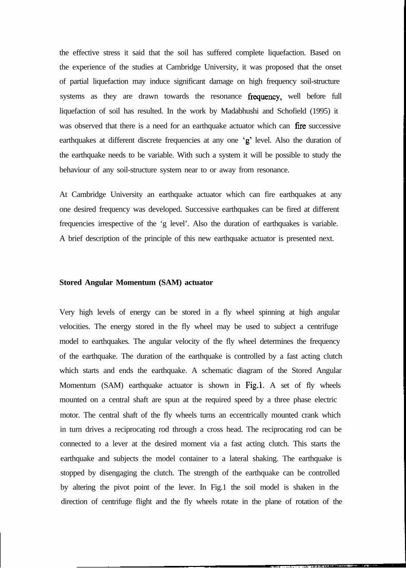
the effective stress it said that the soil has suffered complete liquefaction. Based on
the experience of the studies at Cambridge University, it was proposed that the onset
of partial liquefaction may induce significant damage on high frequency soil-structure
systems as they are drawn towards the resonance frequency, well before full
liquefaction of soil has resulted. In the work by Madabhushi and Schofield (1995) it
was observed that there is a need for an earthquake actuator which can fne successive
earthquakes at different discrete frequencies at any one ‘g’ level. Also the duration of
the earthquake needs to be variable. With such a system it will be possible to study the
behaviour of any soil-structure system near to or away from resonance.
At Cambridge University an earthquake actuator which can fire earthquakes at any
one desired frequency was developed. Successive earthquakes can be fired at different
frequencies irrespective of the ‘g level’. Also the duration of earthquakes is variable.
A brief description of the principle of this new earthquake actuator is presented next.
Stored Angular Momentum (SAM) actuator
Very high levels of energy can be stored in a fly wheel spinning at high angular
velocities. The energy stored in the fly wheel may be used to subject a centrifuge
model to earthquakes. The angular velocity of the fly wheel determines the frequency
of the earthquake. The duration of the earthquake is controlled by a fast acting clutch
which starts and ends the earthquake. A schematic diagram of the Stored Angular
Momentum (SAM) earthquake actuator is shown in Fig.1. A set of fly wheels
mounted on a central shaft are spun at the required speed by a three phase electric
motor. The central shaft of the fly wheels turns an eccentrically mounted crank which
in turn drives a reciprocating rod through a cross head. The reciprocating rod can be
connected to a lever at the desired moment via a fast acting clutch. This starts the
earthquake and subjects the model container to a lateral shaking. The earthquake is
stopped by disengaging the clutch. The strength of the earthquake can be controlled
by altering the pivot point of the lever. In Fig.1 the soil model is shaken in the
direction of centrifuge flight and the fly wheels rotate in the plane of rotation of the

centrifuge arm: alternatively the system could have the soil model sh&en
perpendicular to the plane of rotation of the centrifuge. A more detailed description of
the SAM actuator will be presented elsewhere, Madabhushi and Lesley (1996). The
salient features of the SAM actuator are outlined here.
i) frequency of choice: the earthquake can be fired at a desired frequency or may
sweep through a range of frequencies, for example from 0 Hz to 150 Hz.
ii) ‘g’ level of choice: earthquakes can be fired at different ‘g’ levels. The system is
designed for centrifuge tests conducted at upto 1 OOg.
iii) earthquake strength of choice: it is hoped that the actuator can impart a small
strength earthquake with swept sine wave input motion or a large earthquake at one
frequency (a tone burst). The strength of the earthquake will be changeable.
iv) duration of choice: Another feature is that the duration of the earthquake can be
changed. A possible range of earthquake duration may be from 50 ms to 500 ms.
* The present version of SAM actuator at Cambridge uses BumpyRoad actuator’s Blue face plate to convert reciprocating rod motion
to lateral shaking of the model
1 motor &
11 Timing
Soilmodelto be
shaken
Directionof shaking
Fig. 1 Schematic diagram* showing the plan view ofStored Angular Momentum (SAM) shaker
tDirection
of rotation ofthe centrifuge

Initial Centrifuge Tests
This preliminary report presents the data from the first few centrifuge tests conducted
aboard the 10m beam centrifuge at Cambridge University using the new Stored
Angular Momentum (SAM) actuator. The aim of these initial experiments was to
verify the working principles of the SAM actuator and to prove that strong
earthquakes can be generated using this new actuator.
It was decided that the initial centrifuge tests will be conducted at 40g and the g level
will be increased in each of the subsequent tests. In this report data fi-om a centrifuge
test conducted at 60g are presented. Experiments are currently underway to increase
the working envelope of the SAM actuator to a further level of 90g.
Model Preparation and Test Configuration
A simple horizontal sand bed was chosen as the centrifuge model to be used in the
in&l centrifuge tests. The sand used in these experiments was LB 100/l 70 grade fine
sand. A uniform sand bed was prepared by raining sand from a hopper into an
Equivalent Shear Beam (ESB) box from a predetermined height to give a medium
dense soil sample. The dry density of the sample was calculated as 1614.5 kg/m3.
This gives a void ratio of 0.64 from which the relative density of the sample is
calculated as 80.6%.
A schematic section of the model showing the position of the accelerometers is
presented in Fig.2.
The ESB box (Schofield and Zeng, 1992) was designed to simulate semi-infinite
boundaries at 5Og as the stiffness of sand layer at that g level will match the stiffness
of the end walls. This will enable the wall to undergo the same deformation pattern as
the shear deformation in soil during earthquake loading. Also thin, inextensible shear
sheets are used to generate the complementary shear stresses. Madabhushi, Schofield
and Zeng (1993) describe the efficacy of the shear sheets in generating the
complementary shear stresses. It must be pointed out that use of this ESB box at ‘g’
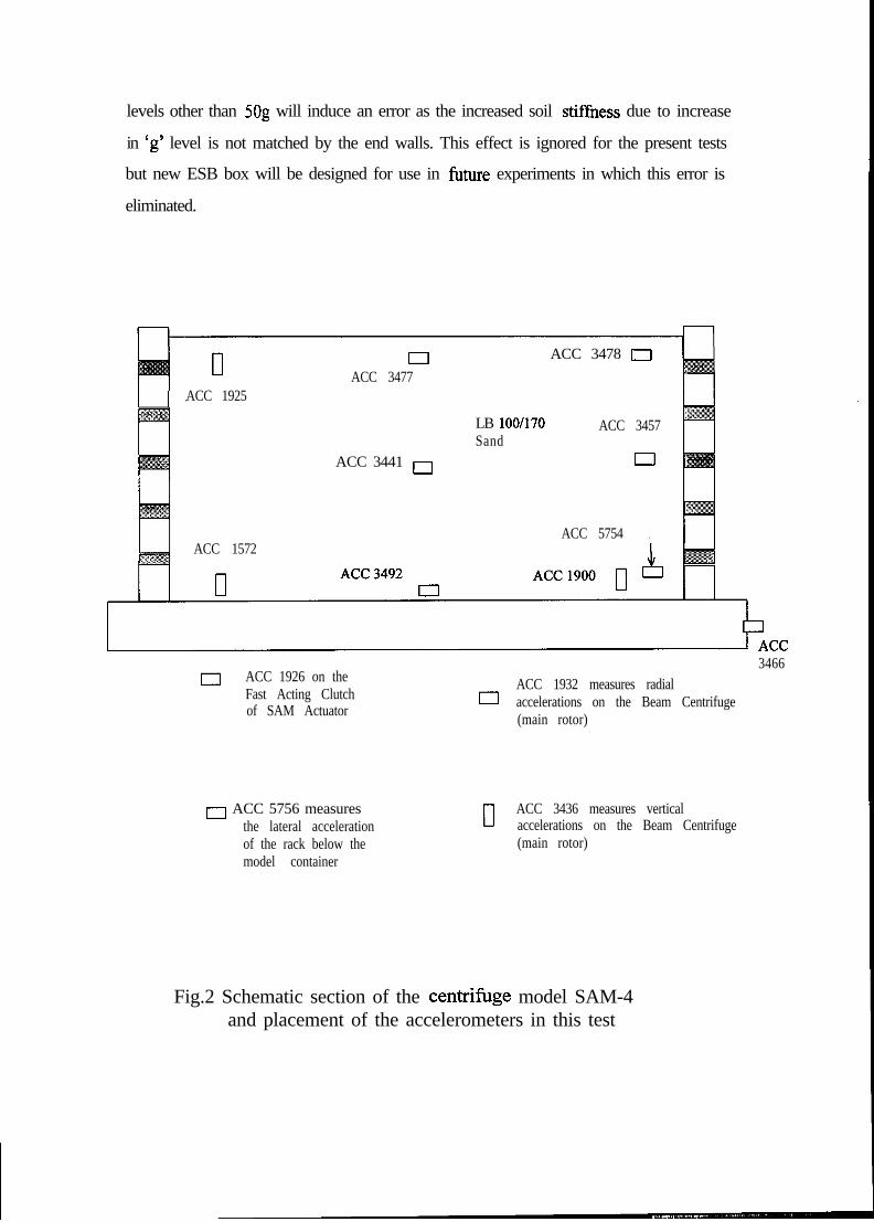
levels other than 5Og will induce an error as the increased soil stiffhess due to increase
in ‘g’ level is not matched by the end walls. This effect is ignored for the present tests
but new ESB box will be designed for use in future experiments in which this error is
eliminated.
ElACC 3477
ACC 3478 0
ACC 1925
ACC 3441 0
LB 100/170Sand
ACC 3457
0
ACC 5754 ,ACC 1572
0 ACC 1926 on theFast Acting Clutch 0of SAM Actuator
0 ACC 5756 measuresthe lateral accelerationof the rack below themodel container
II
3466ACC 1932 measures radialaccelerations on the Beam Centrifuge(main rotor)
ACC 3436 measures verticalaccelerations on the Beam Centrifuge(main rotor)
Fig.2 Schematic section of the centrifbge model SAM-4and placement of the accelerometers in this test
Earthquake Firing Procedure
The following procedure was adopted before firing an earthquake. The three phase
motor is switched on and the speed of the three phase motor is increased until the
main flywheels are spinning at the with the same angular velocity as the desired
frequency of the earthquake. This is done by using a three phase inverter installed in
the centrifuge control room. Once the required angular velocity of the fly wheels is
achieved the required offset on the blue face plate (refer to Kutter, 1982) is driven by
using a second smaller three phase motor. The timing sequence to operate the
pneumatic valves which open the high pressure hydraulic fluid to the clutch is
engaged. This automatically fires the earthquake after a pre-set duration. Also the
clutch is vented to atmosphere automatically by the timing sequence at the end of the
earthquake duration. After the earthquake is finished the timing circuit is switched off
and the three phase motor is stopped bringing the fly wheels to a gradual halt.
Earthquake 1
The speed of the centrifuge was increased gradually so that the centrifuge model was
at 60g. Earthquake 1 was fired by dialling a modest offset to generate a medium sized
earthquake. The speed of the three phase motor was increased gradually so that the
angular velocity of flywheels was 50 Hz. This is expected to generate an earthquake
which has a predominant frequency of 50 Hz.
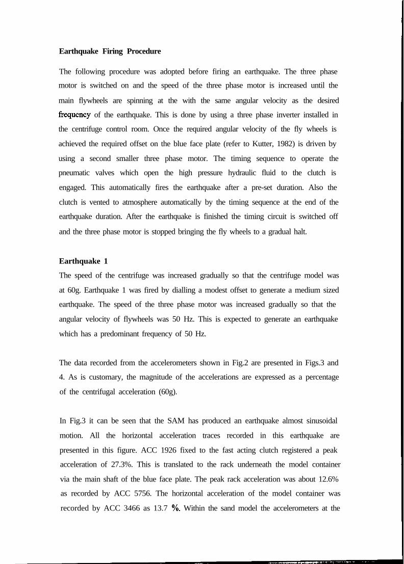
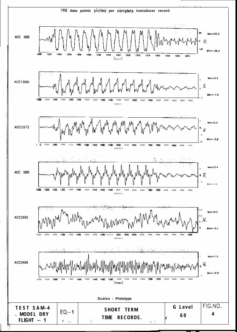
The data recorded from the accelerometers shown in Fig.2 are presented in Figs.3 and
4. As is customary, the magnitude of the accelerations are expressed as a percentage
of the centrifugal acceleration (60g).
In Fig.3 it can be seen that the SAM has produced an earthquake almost sinusoidal
motion. All the horizontal acceleration traces recorded in this earthquake are
presented in this figure. ACC 1926 fixed to the fast acting clutch registered a peak
acceleration of 27.3%. This is translated to the rack underneath the model container
via the main shaft of the blue face plate. The peak rack acceleration was about 12.6%
as recorded by ACC 5756. The horizontal acceleration of the model container was
recorded by ACC 3466 as 13.7 %. Within the sand model the accelerometers at the

base of the model ACC’s 3492 and 5754 measure peak accelerations of 14.7% and
15.3% respectively. The accelerometers at the mid depth of the sand model ACC’s
3441 and 3457 record peak accelerations of 17.5% and 21.3%. The accelerometer just
below the ground surface ACC 3477 recorded a peak ground acceleration of 20.5%.
Considering the traces ACC 3492,344l and 3477 it may be concluded that there is an
amplification of accelerations as the stress waves travel from the base of the model to
the soil surface. ACC 3478 did not function in this test.
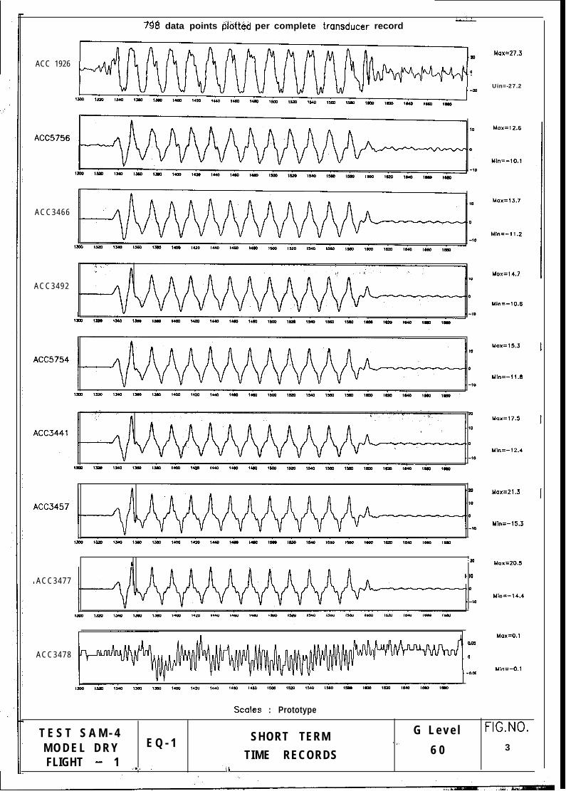
In Fig.4 the vertical accelerations recorded in the sand model during this earthquake
are presented. Also the beam centrifuge itself was monitored in two directions to see
if the SAM actuator causes any undue vibrations of the main centrifuge rotor. This
data is also presented in this figure. ACC1926 is reproduced at the top in this figure.
The vertical accelerometers at the base of the sand model ACC’s 1900 and 1572
recorded a peak vertical acceleration of 2.9% and 2.5% respectively. This vertical
acceleration is also amplified as the stress waves travel to the soil surface. This is
recorded by ACC 1572 which recorded a peak vertical acceleration of 3.4%.
ACC 1932 which records the radial acceleration did not measure any significant radial
acceleration of the beam centrifuge. The peak accelerations was only about 0.3%.
ACC3436 which measures the vertical acceleration of the beam recorded a peak
vertical acceleration of 1.3%. Also the trace indicates high frequency vibration. These
two accelerometers suggest that the SAM actuator is not causing any undue vibrations
in the main rotor arm of the centrifuge during the earthquake.
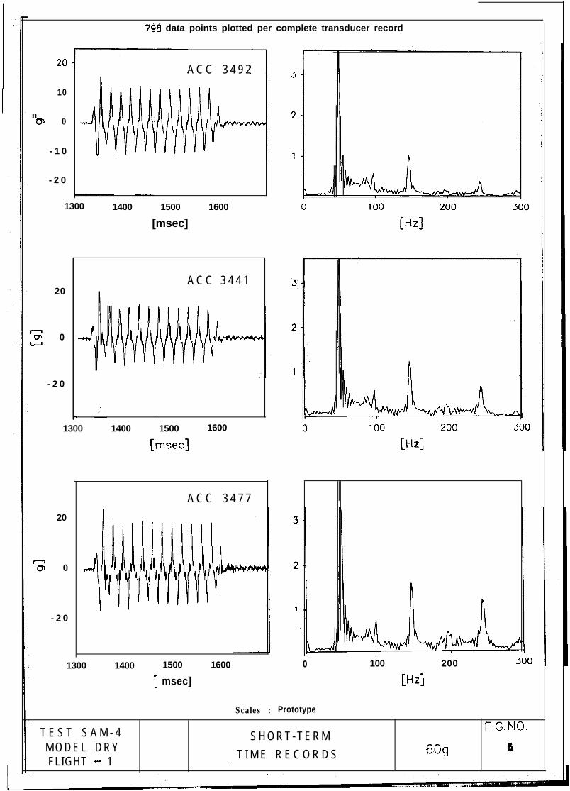
In Fig. 5 the frequency analysis of the acceleration-time histories of three
accelerometers ACC 3492, 3441 and 3477 are presented. The frequency analysis of
ACC 3492 suggests that the predominant frequency of the earthquake was indeed 50
HZ. Also some energy is present at higher harmonics namely 150 Hz and 250 Hz. A
similar observation can be made in the case of the frequency analyses of ACC’s 3441
and 3477. However, it is interesting to note that the high frequency Components Of
150 HZ and 250 HZ are amplified more as the stress waves are travelling from the base
of the model (ACC3492) to the soil surface (ACC3477).
798 data points #tteiJ per complete transducer record
ACC 19260
ACC3466
ACC3492
.m
ACC3477
Lo5
ACC3478 0
Uox=27.3
Uin=-27.2
Uin=-10.8
Mb=-11.8
Mb=-12.4
Uin=-15.3
Max=20.5
Min=-14.4
Max=O.l
Uin=-0.1
Stoles : Prototype
T E S T S A M - 4M O D E L D R Y E Q - 1FLIGHT - 1 ,.,. ,i
SHORT TERM G L e v e l FIG.NO.j 1.
TIME RECORDS 6 0 3
I ih
7$8 data points plotfed per c&nplete transducer record
ACC 1926
ACC1 5 7 2
ACC1900
ACC 1925
ACC1932
ACC3436
[ m s e c ]
I13w 1 3 2 0 1340 1 3 6 0 ,360 1400 1 4 2 0 1 4 4 0 I.60 1460 1 5 0 0 1 5 2 0 1540 1 5 6 0 1560 1 6 0 0 1 6 2 0 1 6 4 0 1 6 6 0 1 6 6 0
I
[msec]
0 1 3 2 0 13W 1 3 6 0 1 3 6 0 1400 1420 l&O W(Y) 1480 t500 1 5 2 0 1540 1 5 6 0 1580 1600 1 6 2 0 1640 1 6 6 0 1 6 6 0
[ m s e c ]
2Mox=2.9
E0
Mill=-1.9- 2
2Max=2.5
0F
- 2
Min=-3.8-4
2Mox=3.4
0s
- 2M i n = - 3 . 3
,300 ,320 ,540 1360 1 3 6 0 1,OO 1 4 2 0 1440 1460 ,480 I W O 1 5 2 0 1 5 4 0 1 5 6 0 1560 16W 1 6 2 0 1 6 4 0 1 6 6 0 1 6 6 0
[ m s e c ]
1 3 0 0 1 3 2 0 1 3 4 0 1360 1 3 6 0 14W 1 4 2 0 1 4 4 0 1460 1 4 6 0 lso0 1520 1540 1 5 6 0 1 6 6 0 1 6 0 0 1 6 2 0 1 6 4 0 1 6 6 0 1680
[ m s e c ]
0 . 3Max=O.J
0 . 2
60 . 1 -
0 Min=-0.1
1 uax=1.3
60-
Min=-0.9- 1
I1 3 0 0 1 3 2 0 13.0 , 3 6 0 , 3 6 0 ,,OO 1 4 2 0 l,,O 14W 1460 1 5 0 0 1 5 2 0 1 5 4 0 1 5 6 0 1560 1600 1 6 2 0 1 6 4 0 1 6 6 0 1 6 6 0
[msec]
Scales : Prototype
T E S T S A M - 4 SHORT TERM G L e v e l FIG.NO.
. MODEL DRY iQ,- 1TIME RECORDS. 4 6 0 4
FLIGHT * 1 .Y .?, ‘I .,~ :._
798 data points plotted per complete transducer record
10
n0, 0
- 1 0
- 2 0
A C C 3 4 9 2
1300
20
-0, 0U
- 2 0
1400 1500 1600
[msec]
A C C 3 4 4 1
I- ’
1300 1400 1500 1600
[‘msec]
20
7s 0
- 2 0
A C C 3 4 7 7
1300 1400 1500
[ msec]
1600 0 100 200
Ml
Scales : Prototype
T E S T S A M - 4 FIG.NO.S H O R T - T E R M
M O D E L D R Y I T I M E R E C O R D S 609 5FLIGHT - 1

Earthquake 2
Earthquake 2 was fired by dialling a modest offset to generate a strong earthquake.
The speed of the three phase motor was increased gradually so that the angular
velocity of flywheels was 50 Hz. This is expected to generate an earthquake which has
a predominant frequency of 50 Hz.
The data recorded Ii-om the accelerometers shown in Fig.2 are presented in Figs.6 and
7. As is customary, the magnitude of the accelerations are expressed as a percentage
of the centrifugal acceleration (60g).
In Fig.6 it can be seen that the SAM has produced an earthquake almost sinusoidal
motion. All the horizontal acceleration traces recorded in this earthquake are
presented in this figure. ACC 1926 fixed to the fast acting clutch registered a peak
acceleration of 26.5%. This is translated to the rack underneath the model container
via the main shaft of the blue face plate. The peak rack acceleration was about 26.4%
as recorded by ACC 5756. The horizontal acceleration of the model container was
recorded by ACC 3466 as 26.9 %. Within the sand model the accelerometers at the
base of the model ACC’s 3492 and 5754 measure peak accelerations of 28.9% and
27.8% respectively. The accelerometers at the mid depth of the sand model ACC’s
3441 and 3457 record peak accelerations of 31.9% and 33.3%. The accelerometer just
below the ground surface ACC 3477 recorded a peak ground acceleration of 33.3%.
This second earthquake has indeed resulted in much stronger accelerations compared
to Earthquake 1. This is due to the larger offset driven in the blue face plate. Also,
considering the traces ACC 3492,344l and 3477, it may be concluded that there is an
amplification of accelerations as the stress waves travel from the base of the model to
the soil surface. ACC 3478 did not function in this test.
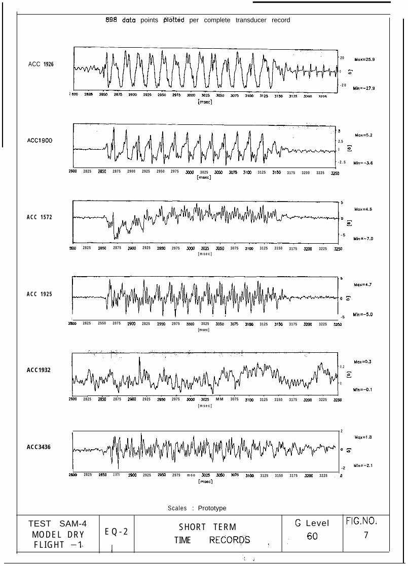
In Fig.7 the vertical accelerations recorded in the sand model during this earthquake
are presented. Also the beam centrifuge itself was monitored in two directions to see
if the SAM actuator causes any undue vibrations of the main centrifuge rotor. This
data is also presented in this figure. ACC1926 is reproduced at the top in this figure.

The vertical accelerometers at the base of the sand model ACC’s 1900 and 1572
recorded a peak vertical acceleration of 5.2% and 4.6% respectively. This vertical
acceleration is also amplified as the stress waves travel to the soil surface. This is
recorded by ACC 1572 which recorded a peak vertical acceleration of 4.7%. It
appears that during this earthquake the vertical acceleration traces include higher
frequency components.
ACC 1932 which records the radial acceleration did not measure any significant radial
acceleration of the beam centrifuge. The peak accelerations was only about 0.3%.
ACC3436 which measures the vertical acceleration of the beam recorded a peak
vertical acceleration of 1.8%. Also the trace indicates high frequency vibration. These
two accelerometers reinforce the fact that the SAM actuator is not causing any undue
vibrations in the main rotor arm of the centrifuge during the earthquake.
In Fig. 8 the frequency analysis of the acceleration-time histories of three
accelerometers ACC 3492, 3441 and 3477 are presented. The frequency analysis of
ACC 3492 suggests that the predominant frequency of the earthquake was indeed 50
Hz. Also some energy is present at higher harmonics namely 150 Hz and 250 Hz. A
similar observation can be made in the case of the frequency analyses of ACC’s 3441
and 3477. However, it is interesting to note that the high frequency components of
150 Hz and 250 Hz are amplified more as the stress waves are travelling from the base
of the model (ACC3492) to the soil surface (ACC3477).
Conclusions
Based on the data recorded in the two earthquakes of this centrifuge test SAM-4 it is
concluded that the Stored Angular Momentum (SAM) actuator is viable device to
generate strong earthquakes of desired frequency and duration. This is considered to
be a major development in research position from the Bumpy Road actuator as the
SAM actuator is relatively cheap to construct and does not sufl?er from many of the
limitations of the Bumpy Road like the fixed frequency earthquakes or fixed duration
earthquakes. Also it is possible to design future versions of the SAM actuator which

8&1 data paints f5khd per completi transducer record
t-74
.m.,ACC3466 .o E
.’$ .a0
ACC3492 D E
A C C 3 4 4 1
Mox=26.5
Min=-27.2
Max=26.4
Min=-16.9
Max=X.9
thin=-21.4
Max=28.9
hiin=-20.4
Max=27.8
Mb=-22.7
t&n=-25.7
Min=-27.0
Min=-28.0
Mox=O.2
Mb-t=-0.6
Scales : P r o t o t y p e
T E S T S A M - 4 SHORT TERM G L e v e l FIG.NO.
M O D E L D R Y E Q - 2 6 0 6
F L I G H T -1 ‘91” jl T I M E RECORD3 “i
ACC 1926
: :8198 data points @laitetd per complete transducer record
20 Max=25.9
0 z
- 2 0Mill=-27.9
2
[msec]
ACC1900
A C C 1 5 7 2
A C C 1 9 2 5
ACC1932
ACC3436
6Max=5.2
2.5
0 E
- 2 . 5 Min=-3.6
2aW 2825 2850 2875 2900 2925 2950 2975 3Yoo 3025 3050 3075 31w 3125 3150 3175 3200 3225 3250[msec]
- 5Min=-7.0
!000 2825 2850 2875 2900 2925 2950 2975 3WO 3025 5054 3075 3100 3125 3150 3175 3200 3225 3254l[msec]
OZ
I. I Mln=-5.0
-52eW 2825 2550 2075 2SW 2825 2950 2975 3ooo 3025 3050 xl75 3lQo 3125 3150 3175 3200 3225 3200
[msec]
Max=O.J0 . 2
E
0uinc-0.1
2aw 2825 2850 2875 2900 2925 2950 2975 mail 3025 MM 3075 3100 3125 3150 3175 32W 3225 3250[msec]
I2aW 2825 2a50 2.975 2900 2925 2950 2975 moo 3025 3054 5075 3100 3125 3150 3175 32W 3225 :
[msec]
2Max=l.0
03
-2 ml=-2.1
, O
Scales : Prototype
TEST SAM-4 SHORT TERM G Level FIG.NO.
MODEL DRY E Q - 2 7FLIGHT -1, TIME RECORDS ” ‘. ”
’1 ,!,. .i

7% data points plotted per complete transducer record
2 0 6-
T;;: 0 4-
- 2 0 2-
- 4 02 8 0 0 2 9 0 0 3 0 0 0 3 1 0 0 3 2 0 0 0 1 0 0 2 0 0 3 0 0
[msec J D-M
4 0
2 0 6-
T;;: 0 4.
- 2 0 2 -
- 4 02 8 0 0 2 9 0 0 3 0 0 0 3 1 0 0 3 2 0 0 0 1 0 0 2 0 0 3 0 0
[ msec] 0-M
2 0 6
r;;: 0 4
- 2 0 2
- 4 0 1 - I2 8 0 0 2 9 0 0 3 0 0 0 3 1 0 0 3 2 0 0 0 1 0 0 2 0 0 3 0 0
[ m s e c ] v-4
Scales : Prototype
T E S T S A M - 4 l=lG.NO.E Q - 2 SHORT-TERM
MODEL DRY 609 8F L I G H T - 1 TIME RECORDS
can work in even higher ‘g’ environments as the device relies on extremely simple
components for examples fly wheels, bearings, three phase motor and a fast acting
clutch.
Future Work
It is anticipated that in coming weeks the working of the SAM actuator will be
extended from 60g to 90g at first and then to the designed ‘g’ level of 1OOg. This
would need some changes to the existing three phase motor. A stronger motor with a
larger starting torque is need to start the flywheels at 1OOg. Also the present system is
working with pneumatic valves which start and stop the earthquake. The response of
the system can be improved by using servo-hydraulic valves. Initial attempts of using
servo-hydraulic valves were not successful due to the failure of the later to work in
high ‘g’ environments. Better servo-hydraulic valves are currently being looked into
to further improve the response of the fast acting clutch.
ACKNOWLEDGEMENTS
The author wishes to express his sincere thanks to Mr. Chris Collison and Mr. Paul
Ford for all the help rendered in the commissioning of the SAM actuator on the 10m
beam centrifuge. Thanks are also due to Mr. Navin Pieries for helping with the initial
experiments. The constant encouragement of Prof. Andrew Schofield and Dr.Malcolm
Bolton, without whose support this work would not have been possible, is gratefully
acknowledged.
REFERENCES
1. Kutter, B.L., (1982), Centrifugal modelling of response of clay embankments toearthquakes, Ph.d thesis, Cambridge University, England.
2. Madabhushi, S.P.G and Lesley, S., (1996), Design and construction of a StoredAngular Momentum (SAM) based of earthquake actuator, CUED report (underpreparation), Cambridge University.
3. Madabhushi, S.P.G. and Schofield A.N., (1993), Response of tower structuressubjected to earthquake perturbations, Geotechnique, Vo1.43, No.4.

4. Madabhushi, S.P.G. and Schofield, A.N., (1995), Simulation of earthquakes in ageotechnical centrifuge, I Intl. Conf. on Earthquake Geotechnical Engineering, IS-Tokyo’95, Tokyo, Japan.
5. Madabhushi, S.P.G., Schofield, A.N. and Zeng, X., (1994), Complementary ShearStresses in Dynamic Centrifuge Modelling, Dynamic Geotechnical Testing:Second Volume, ASTM STP1213, Ronald I. Ebelhar, Vincent P. Drnevich andBruce L. Kutter, Eds., American Society for Testing and Materials, Philadelphia.
6. Schofield, A.N.,( 1980), Cambrid eGeotechnique, Vo1.25., No.4, pp 743- 7 61.
geotechnical centrifuge operations,
7. Schofield, A.N.,(1981), Dynamic and Earthquake geotechnical centrifugemodelling, Proc. Recent Advances in Geotech. Earthquake Eng. Soil dynamicsand earthquake eng., Univ. of Missouri-Rolla, Rolla.
8. Schofield, A.N. and Lee, F.H., (1988), Centrifuge modelling of sand embankmentsand islands in earthquakes, Geotechnique, Vo1.38, No. 1.
9. Schofield, A.N. and Zeng, X., (1992), Design and performance of an equivalent-shear-beam (ESB) container for earthquake centrifuge modelling, TechnicalReport, CUED/D-SoilslTR245, Cambridge University, UK.
10. Zeng, X. and Steedman, R.S., (1993), On behaviour of quay walls in earthquakes,Geotechnique, Vo1.43, No.3, pp 417-43 1.