sphere-rol bearingsimaya.biz/uploads/file/20160416/20160416183833_10579.pdf · sphere-rol®...
TRANSCRIPT
D-1
Sph
ere
-Ro
l B
ea
rin
gs
D-2
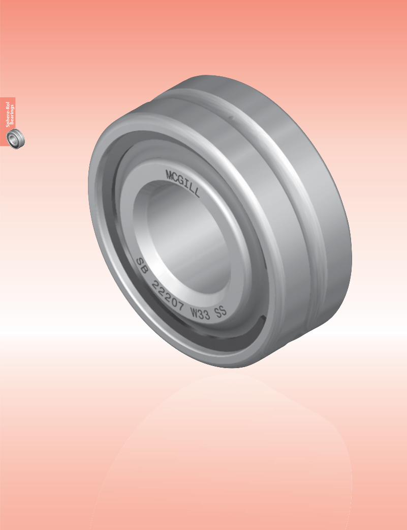
Spherical RollerUnmounted bearing assembly consisting
of through hardened inner and outer
raceways with single spherical rolling
elements separated by steel land riding
retainer (cage) and available with
several seal options. SPHERE-ROL® roller
bearings provide an antifriction solution
when supporting rotating shafts with
combination radial and thrust loads.
Bearing Configurations
Sealed / unsealed, straight or tapered bore
Bore Diameter Size Range
20 mm to 150 mm (.5906” to 5.9055”)
Materials
Bearing Quality SteelSp
he
re-R
ol
Be
ari
ng
s
SPHERE-ROL® Spherical Bearings
D-3
Sph
ere
-Ro
l B
ea
rin
gs
SIZE RANGE
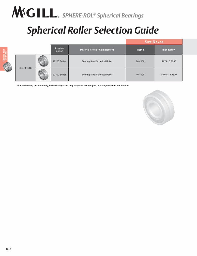
Product Series Material / Roller Complement Metric Inch Equiv
SHERE-ROL
22200 Series Bearing Steel Spherical Roller 20 - 150 .7674 - 5.9055
22300 Series Bearing Steel Spherical Roller 40 - 100 1.5748 - 3.9370
�������������������������� ��� ������!���������� ����"#�����������$�����������������
Spherical Roller Selection Guide
SPHERE-ROL® Spherical Bearings
D-4
Sph
ere
-Ro
l B
ea
rin
gs
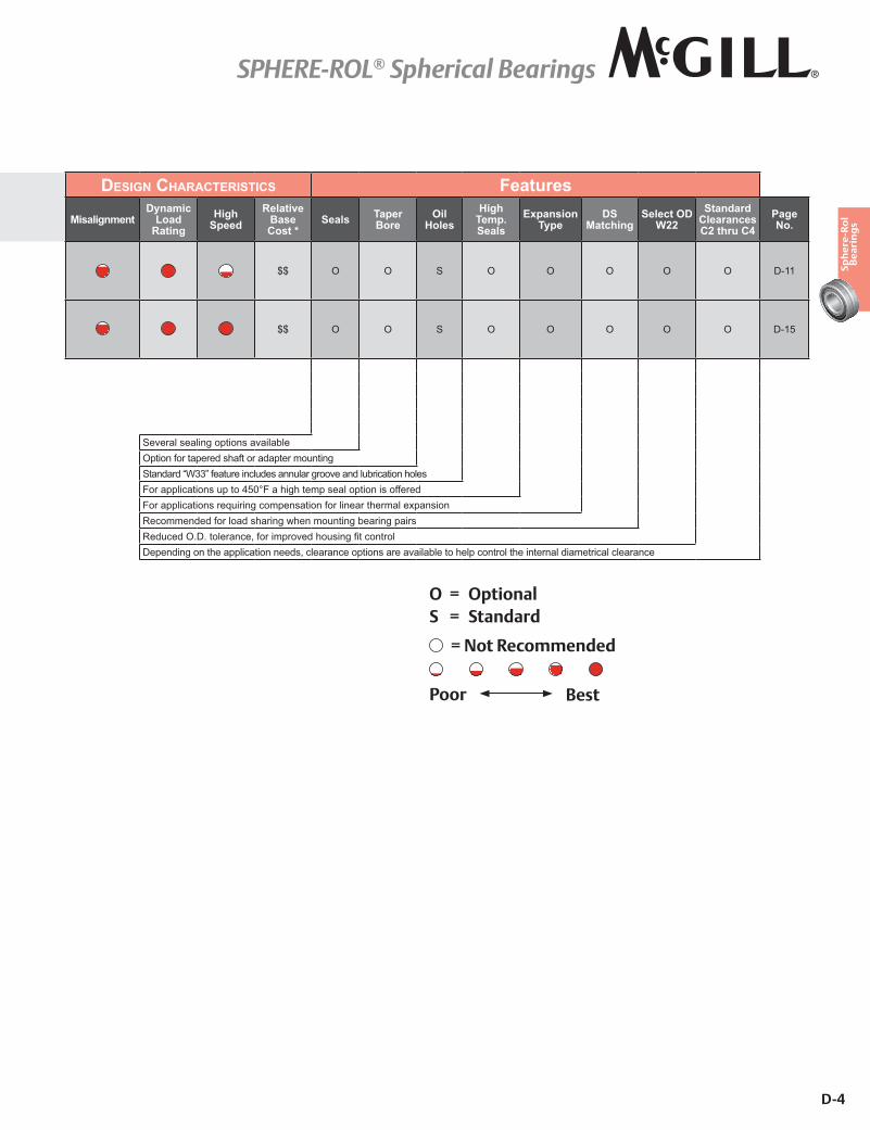
DESIGN CHARACTERISTICS Features
MisalignmentDynamic
Load Rating
High Speed
Relative Base Cost *
Seals Taper Bore
Oil Holes
High Temp. Seals
Expansion Type
DS Matching
Select OD W22
Standard Clearances C2 thru C4
Page No.
$$ O O S O O O O O D-11
$$ O O S O O O O O D-15
Several sealing options availableOption for tapered shaft or adapter mountingStandard “W33” feature includes annular groove and lubrication holesFor applications up to 450°F a high temp seal option is offeredFor applications requiring compensation for linear thermal expansionRecommended for load sharing when mounting bearing pairs#�������=�"������������������?���������������������Depending on the application needs, clearance options are available to help control the internal diametrical clearance
O = OptionalS = Standard
Poor Best
= Not Recommended
SPHERE-ROL® Spherical Bearings
D-5
Sph
ere
-Ro
l B
ea
rin
gs
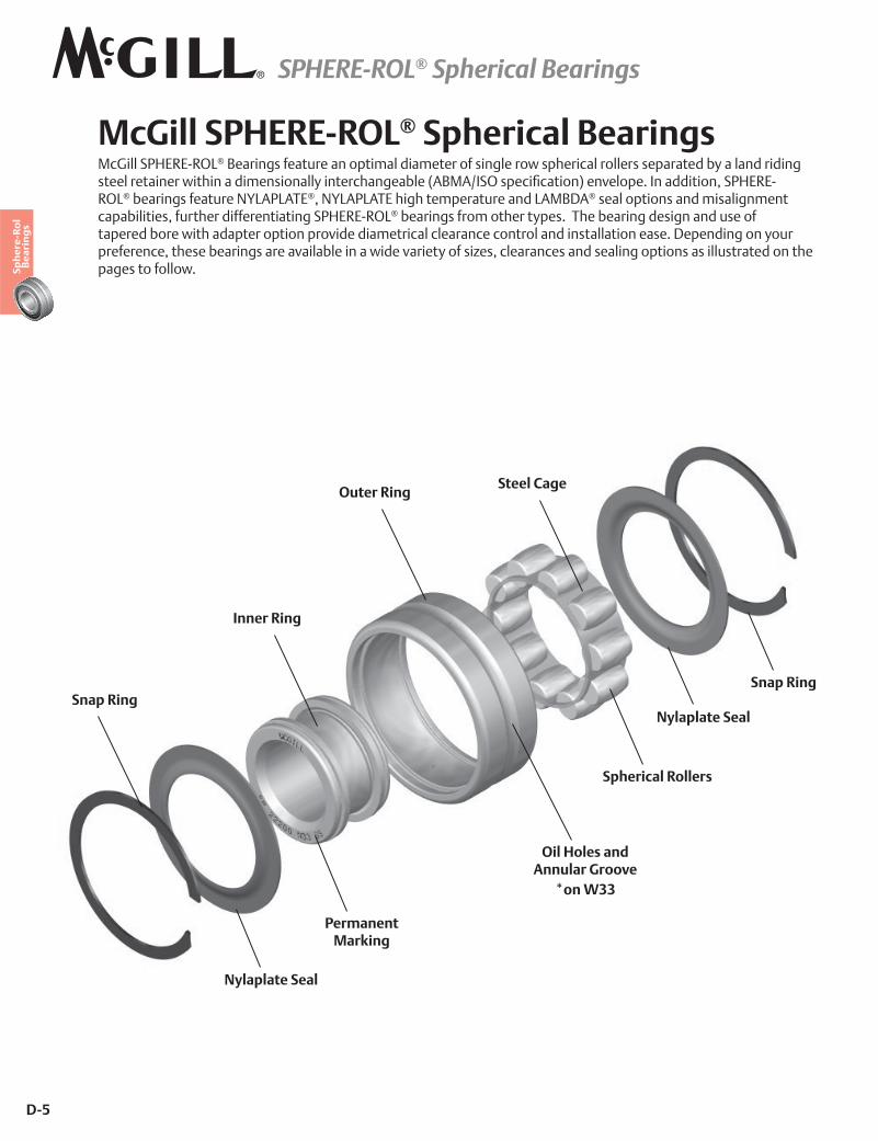
McGill SPHERE-ROL® Spherical BearingsMcGill SPHERE-ROL® Bearings feature an optimal diameter of single row spherical rollers separated by a land riding ������ ������ �!�������������������'����� ������"���_�YX�����������]�����|���*����<���������������£�+�#ROL® bearings feature NYLAPLATE®, NYLAPLATE high temperature and LAMBDA® seal options and misalignment capabilities, further differentiating SPHERE-ROL® bearings from other types. The bearing design and use of tapered bore with adapter option provide diametrical clearance control and installation ease. Depending on your preference, these bearings are available in a wide variety of sizes, clearances and sealing options as illustrated on the pages to follow.
Steel CageOuter Ring
Inner Ring
Snap RingSnap Ring
Spherical Rollers
Permanent Marking
Oil Holes and Annular Groove
*on W33
Nylaplate Seal
Nylaplate Seal
SPHERE-ROL® Spherical Bearings
D-6
Sph
ere
-Ro
l B
ea
rin
gs
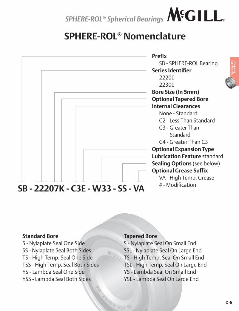
SPHERE-ROL® Nomenclature
Prefix SB - SPHERE-ROL BearingSeries Identifier 22200 22300Bore Size (In 5mm)Optional Tapered BoreInternal Clearances None - Standard C2 - Less Than Standard C3 - Greater Than
Standard C4 - Greater Than C3Optional Expansion TypeLubrication Feature standardSealing Options (see below)Optional Grease Suffix VA - High Temp. Grease� ©�#�X��]������SB - 22207K - C3E - W33 - SS - VA
Standard BoreS - Nylaplate Seal One SideSS - Nylaplate Seal Both SidesTS - High Temp. Seal One SideTSS - High Temp. Seal Both SidesYS - Lambda Seal One SideYSS - Lambda Seal Both Sides
Tapered BoreS - Nylaplate Seal On Small EndSSL - Nylaplate Seal On Large EndTS - High Temp. Seal On Small EndTSL - High Temp. Seal On Large EndYS - Lambda Seal On Small EndYSL - Lambda Seal On Large End
SPHERE-ROL® Spherical Bearings
D-7
Sph
ere
-Ro
l B
ea
rin
gs
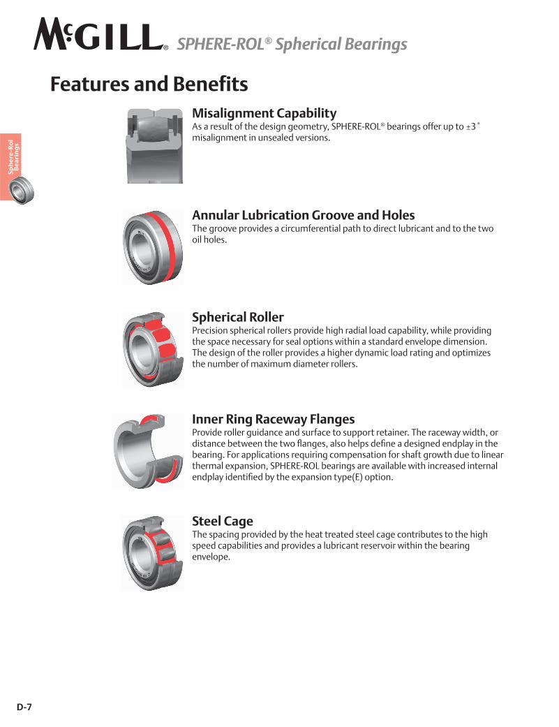
Features and Benefits
Annular Lubrication Groove and HolesThe groove provides a circumferential path to direct lubricant and to the two oil holes.
Misalignment CapabilityAs a result of the design geometry, SPHERE-ROL®�"�� ����@@� ������«;¬�misalignment in unsealed versions.
Spherical RollerPrecision spherical rollers provide high radial load capability, while providing the space necessary for seal options within a standard envelope dimension. The design of the roller provides a higher dynamic load rating and optimizes the number of maximum diameter rollers.
Steel CageThe spacing provided by the heat treated steel cage contributes to the high speed capabilities and provides a lubricant reservoir within the bearing envelope.
Inner Ring Raceway FlangesProvide roller guidance and surface to support retainer. The raceway width, or ���������"��!���������!�`������������������]�������������������'��������bearing. For applications requiring compensation for shaft growth due to linear thermal expansion, SPHERE-ROL bearings are available with increased internal ������'�������]���"'������H��������'��_�|�����<
SPHERE-ROL® Spherical Bearings
D-8
Sph
ere
-Ro
l B
ea
rin
gs
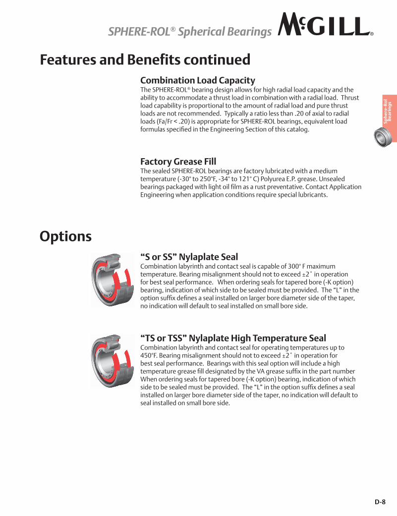
Features and Benefits continuedCombination Load CapacityThe SPHERE-ROL® bearing design allows for high radial load capacity and the ability to accommodate a thrust load in combination with a radial load. Thrust load capability is proportional to the amount of radial load and pure thrust loads are not recommended. Typically a ratio less than .20 of axial to radial loads (Fa/Fr < .20) is appropriate for SPHERE-ROL bearings, equivalent load @ �����������]���������������� ����������@�����������<
Factory Grease FillThe sealed SPHERE-ROL bearings are factory lubricated with a medium temperature (-30° to 250°F, -34° to 121° C) Polyurea E.P. grease. Unsealed "�� �������N����!������������]�������� ����� �*������*�<�������������������Engineering when application conditions require special lubricants.
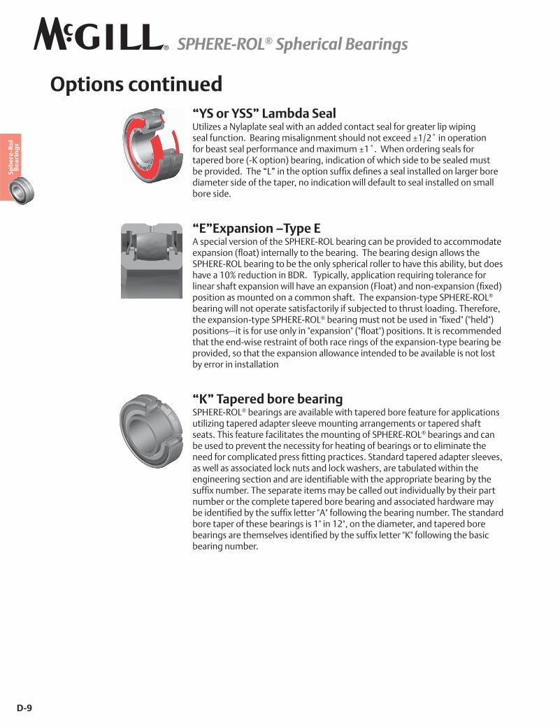
Options“S or SS” Nylaplate SealCombination labyrinth and contact seal is capable of 300° F maximum ����� ��� �<�Y�� ���������������������������H�����«Z¬������ �����for best seal performance. When ordering seals for tapered bore (-K option) bearing, indication of which side to be sealed must be provided. The “L” in the �������@]H���]������������������������� � �" ��������� ������@��������� ��no indication will default to seal installed on small bore side.
“TS or TSS” Nylaplate High Temperature SealCombination labyrinth and contact seal for operating temperatures up to {=~��<�Y�� ���������������������������H�����«Z¬������ �����@ �best seal performance. Bearings with this seal option will include a high ����� ��� �� �����]�������������"'�������� �������@]H���������� �����"� ���When ordering seals for tapered bore (-K option) bearing, indication of which �������"��������������"��� *����<�������$����������������@]H���]�����������installed on larger bore diameter side of the taper, no indication will default to seal installed on small bore side.
SPHERE-ROL® Spherical Bearings
D-9
Sph
ere
-Ro
l B
ea
rin
gs
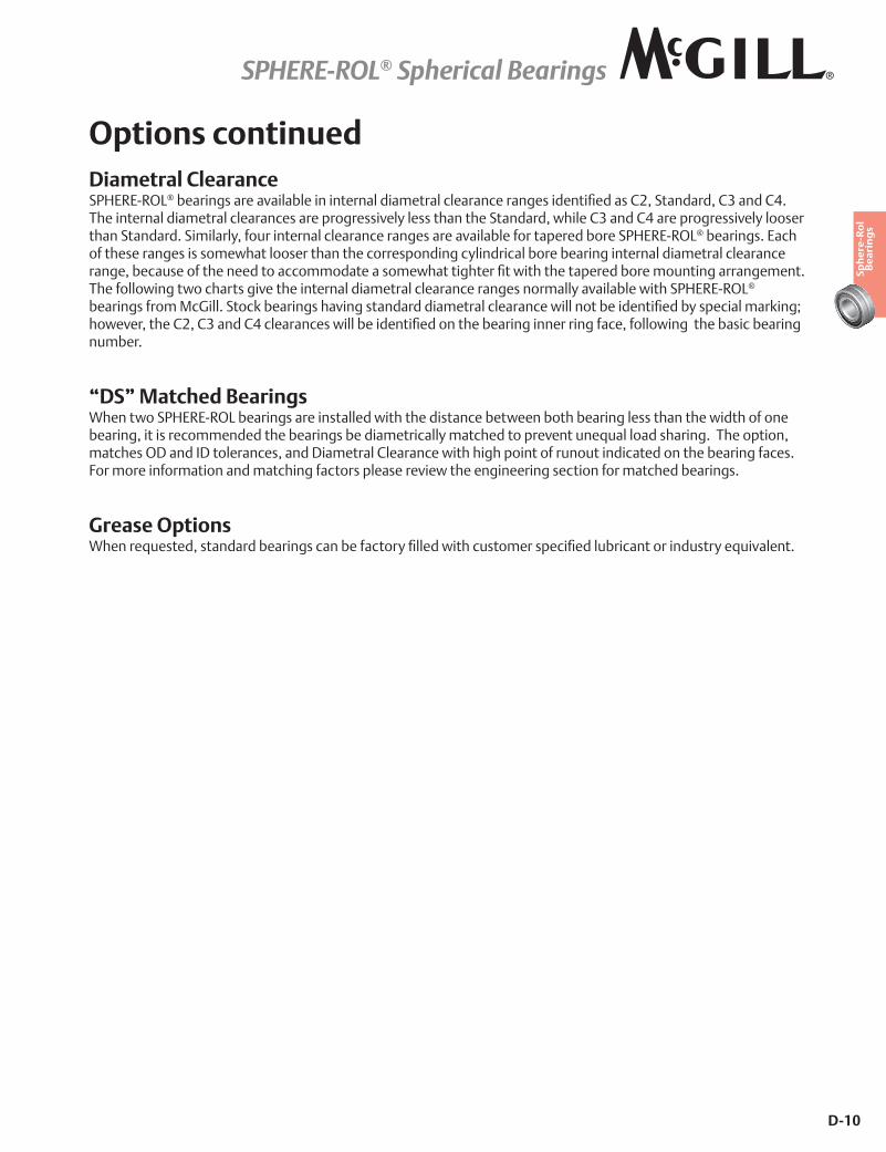
“YS or YSS” Lambda SealUtilizes a Nylaplate seal with an added contact seal for greater lip wiping �����@������<��Y�� �������������������������H�����«��Z¬������ �����@ �"������������ @ ������������H�����«�¬<������� �� ���������@ �tapered bore (-K option) bearing, indication of which side to be sealed must "��� *����<�������$����������������@]H���]������������������������� � �" ��diameter side of the taper, no indication will default to seal installed on small bore side.
“E”Expansion –Type EA special version of the SPHERE-ROL bearing can be provided to accommodate �H�������_`��|����� ����'�������"�� ��<������"�� ������������!������SPHERE-ROL bearing to be the only spherical roller to have this ability, but does have a 10% reduction in BDR. Typically, application requiring tolerance for ����� ����@���H�������!������*������H�������_����|�������#�H�������_]H��|�position as mounted on a common shaft. The expansion-type SPHERE-ROL® bearing will not operate satisfactorily if subjected to thrust loading. Therefore, the expansion-type SPHERE-ROL®�"�� �����������"����������¢]H��¢�_¢����¢|��������������@ �������'����¢�H������¢�_¢`��¢|��������<������� ����������that the end-wise restraint of both race rings of the expansion-type bearing be provided, so that the expansion allowance intended to be available is not lost by error in installation
Options continued
“K” Tapered bore bearingSPHERE-ROL® bearings are available with tapered bore feature for applications utilizing tapered adapter sleeve mounting arrangements or tapered shaft seats. This feature facilitates the mounting of SPHERE-ROL® bearings and can be used to prevent the necessity for heating of bearings or to eliminate the �����@ ������������� ����]������ �������<������� ������ ��������� �����*����as well as associated lock nuts and lock washers, are tabulated within the ������ ��������������� ��������]�"���!����������� � �����"�� ���"'�������@]H����"� <��������� ������������'�"����������������*������'�"'����� ��� ��number or the complete tapered bore bearing and associated hardware may "��������]���"'�������@]H������ �¢�¢�@��!�������"�� ������"� <����������� ��" ������ �@�������"�� ��������¢�����Z¢��������������� ���������� ���" ��"�� ����� ���������*���������]���"'�������@]H������ �¢&¢�@��!�������"�����bearing number.
SPHERE-ROL® Spherical Bearings
D-10
Sph
ere
-Ro
l B
ea
rin
gs
Options continuedDiametral ClearanceSPHERE-ROL®�"�� ����� ���*����"���������� ���������� ������� ����� �����������]�������Z�������� ����;������{<�The internal diametral clearances are progressively less than the Standard, while C3 and C4 are progressively looser than Standard. Similarly, four internal clearance ranges are available for tapered bore SPHERE-ROL® bearings. Each of these ranges is somewhat looser than the corresponding cylindrical bore bearing internal diametral clearance �����"�������@���������������������������!��������� �]��!������������ ���" ���������� �������<�The following two charts give the internal diametral clearance ranges normally available with SPHERE-ROL® "�� ����@ ��X�����<����N�"�� ������*��������� �������� ������� �����!�������"��������]���"'����������� N�����!�*� �������Z���;������{����� ������!����"��������]���������"�� ������� � ���@�����@��!��������"�����"�� ���number.
Grease Options����� ���������������� ��"�� ��������"��@��� '�]�����!���������� ������]�����" ������ ������� '�����*�����<
“DS” Matched BearingsWhen two SPHERE-ROL bearings are installed with the distance between both bearing less than the width of one bearing, it is recommended the bearings be diametrically matched to prevent unequal load sharing. The option, matches OD and ID tolerances, and Diametral Clearance with high point of runout indicated on the bearing faces. For more information and matching factors please review the engineering section for matched bearings.
SPHERE-ROL® Spherical Bearings
D-11
Sph
ere
-Ro
l B
ea
rin
gs
Part No. B D W Bs Ds HG J rLimiting Speed (In Oil)
BDR
Bearing Weight
Base Bearing
Bore Diameter Outside Diameter WidthMin
Shoulder Diameter
Inner
Min Shoulder Diameter
Outer
Annular Lub
Groove
Lambda Seal
Minimum Clearance
Maximum radius or �������clear
Basic Dynamic Rating
mm inch
mm inch
mm inch
mm inch
mm inch
mm inch RPM* N/lb kg
lbNom. Tol. Nom. Tol. Nom. Tol. Ref Ref W33 Ref Ref
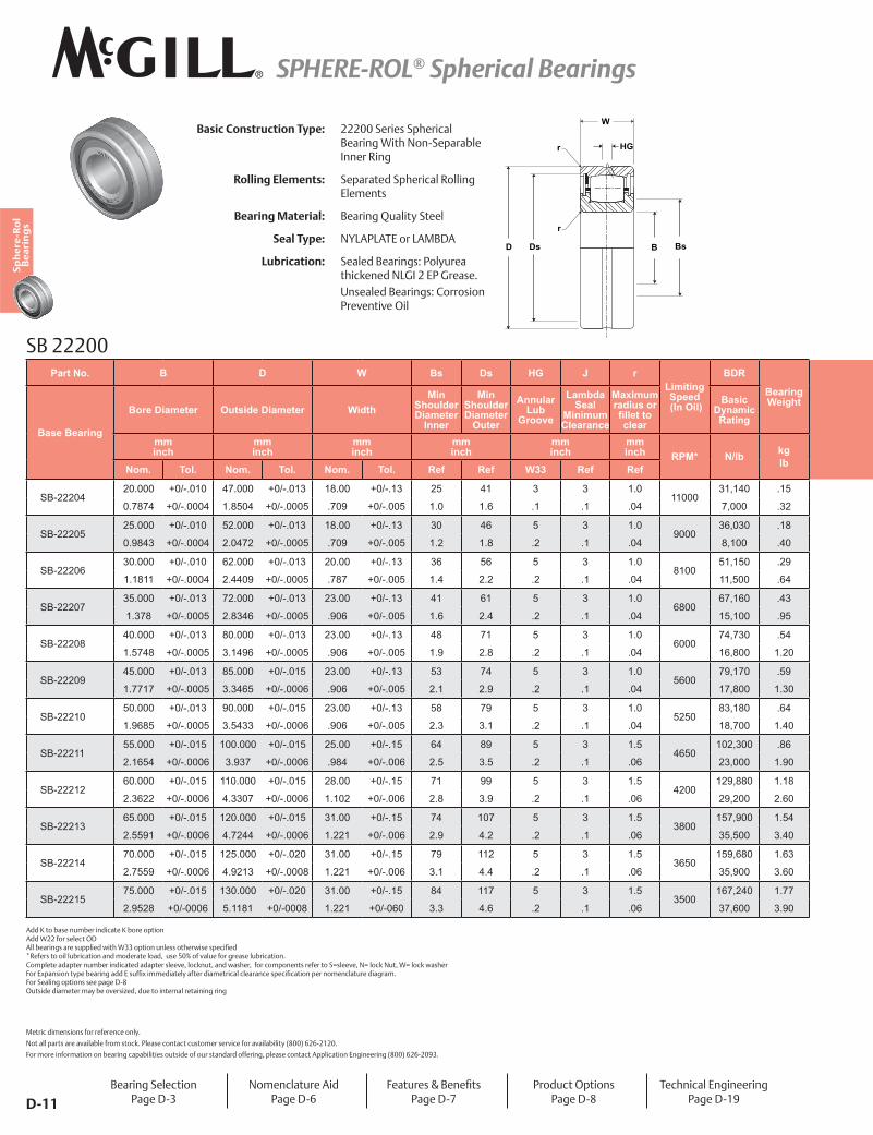
SB-2220420.000 +0/-.010 47.000 +0/-.013 18.00 +0/-.13 25 41 3 3 1.0
1100031,140 .15
0.7874 +0/-.0004 1.8504 +0/-.0005 .709 +0/-.005 1.0 1.6 .1 .1 .04 7,000 .32
SB-2220525.000 +0/-.010 52.000 +0/-.013 18.00 +0/-.13 30 46 5 3 1.0
900036,030 .18
0.9843 +0/-.0004 2.0472 +0/-.0005 .709 +0/-.005 1.2 1.8 .2 .1 .04 8,100 .40
SB-2220630.000 +0/-.010 62.000 +0/-.013 20.00 +0/-.13 36 56 5 3 1.0
810051,150 .29
1.1811 +0/-.0004 2.4409 +0/-.0005 .787 +0/-.005 1.4 2.2 .2 .1 .04 11,500 .64
SB-2220735.000 +0/-.013 72.000 +0/-.013 23.00 +0/-.13 41 61 5 3 1.0
680067,160 .43
1.378 +0/-.0005 2.8346 +0/-.0005 .906 +0/-.005 1.6 2.4 .2 .1 .04 15,100 .95
SB-2220840.000 +0/-.013 80.000 +0/-.013 23.00 +0/-.13 48 71 5 3 1.0
600074,730 .54
1.5748 +0/-.0005 3.1496 +0/-.0005 .906 +0/-.005 1.9 2.8 .2 .1 .04 16,800 1.20
SB-2220945.000 +0/-.013 85.000 +0/-.015 23.00 +0/-.13 53 74 5 3 1.0
560079,170 .59
1.7717 +0/-.0005 3.3465 +0/-.0006 .906 +0/-.005 2.1 2.9 .2 .1 .04 17,800 1.30
SB-2221050.000 +0/-.013 90.000 +0/-.015 23.00 +0/-.13 58 79 5 3 1.0
525083,180 .64
1.9685 +0/-.0005 3.5433 +0/-.0006 .906 +0/-.005 2.3 3.1 .2 .1 .04 18,700 1.40
SB-2221155.000 +0/-.015 100.000 +0/-.015 25.00 +0/-.15 64 89 5 3 1.5
4650102,300 .86
2.1654 +0/-.0006 3.937 +0/-.0006 .984 +0/-.006 2.5 3.5 .2 .1 .06 23,000 1.90
SB-2221260.000 +0/-.015 110.000 +0/-.015 28.00 +0/-.15 71 99 5 3 1.5
4200129,880 1.18
2.3622 +0/-.0006 4.3307 +0/-.0006 1.102 +0/-.006 2.8 3.9 .2 .1 .06 29,200 2.60
SB-2221365.000 +0/-.015 120.000 +0/-.015 31.00 +0/-.15 74 107 5 3 1.5
3800157,900 1.54
2.5591 +0/-.0006 4.7244 +0/-.0006 1.221 +0/-.006 2.9 4.2 .2 .1 .06 35,500 3.40
SB-2221470.000 +0/-.015 125.000 +0/-.020 31.00 +0/-.15 79 112 5 3 1.5
3650159,680 1.63
2.7559 +0/-.0006 4.9213 +0/-.0008 1.221 +0/-.006 3.1 4.4 .2 .1 .06 35,900 3.60
SB-2221575.000 +0/-.015 130.000 +0/-.020 31.00 +0/-.15 84 117 5 3 1.5
3500167,240 1.77
2.9528 +0/-0006 5.1181 +0/-0008 1.221 +0/-060 3.3 4.6 .2 .1 .06 37,600 3.90
SB 22200
D BsBDs
HG
W
r
r
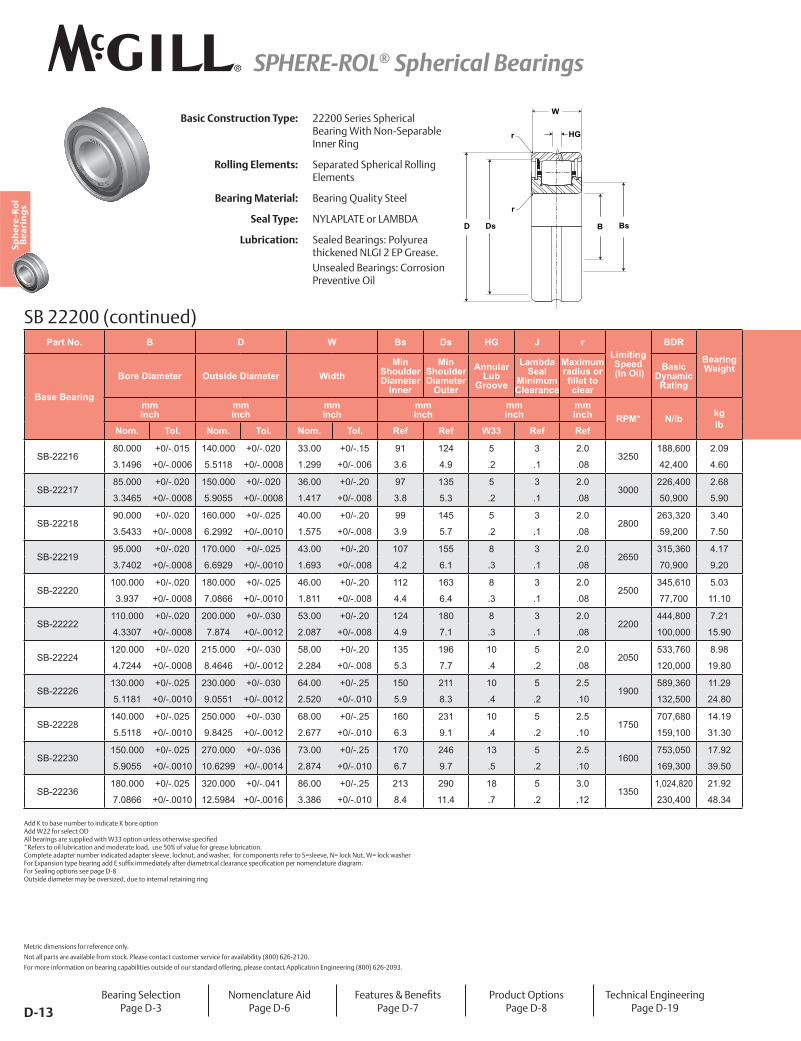
Basic Construction Type: 22200 Series Spherical Bearing With Non-Separable Inner Ring
Rolling Elements: Separated Spherical Rolling Elements
Bearing Material: Bearing Quality Steel
Seal Type: NYLAPLATE or LAMBDA
Lubrication: Sealed Bearings: Polyurea thickened NLGI 2 EP Grease.Unsealed Bearings: Corrosion Preventive Oil
Bearing SelectionPage D-3
Nomenclature AidPage D-6
����� ���7�Y���]��Page D-7
Product OptionsPage D-8
Technical EngineeringPage D-19
Add K to base number indicate K bore option Add W22 for select OD ����"�� ����� �����������!�����;;���������������� !���������]�� *Refers to oil lubrication and moderate load, use 50% of value for grease lubrication. Complete adapter number indicated adapter sleeve, locknut, and washer, for components refer to S=sleeve, N= lock Nut, W= lock washer � ��H��������'���"�� �����������@]H�����������'��@�� ������� ��������� ����������]�������� ���������� ����� ��< For Sealing options see page D-8 Outside diameter may be oversized, due to internal retaining ring
Metric dimensions for reference only.
Not all parts are available from stock. Please contact customer service for availability (800) 626-2120.
For more information on bearing capabilities outside of our standard offering, please contact Application Engineering (800) 626-2093.
SPHERE-ROL® Spherical Bearings
D-12
Sph
ere
-Ro
l B
ea
rin
gs
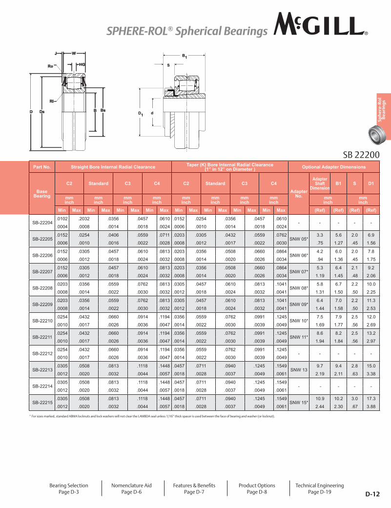
Part No. Straight Bore Internal Radial Clearance Taper (K) Bore Internal Radial Clearance (1” in 12” on Diameter ) Optional Adapter Dimensions
Base Bearing
C2 Standard C3 C4 C2 Standard C3 C4
Adapter No.
Adapter Shaft
DimensionB1 S D1
mm inch
mm inch
mm inch
mm inch
mm inch
mm inch
mm inch
mm inch
mm inch
mm inch
Min Max Min Max Min Max Min Max Min Max Min Max Min Max Min Max (Ref) (Ref) (Ref) (Ref)
SB-22204.0102 .2032 .0356 .0457 .0610 .0152 .0254 .0356 .0457 .0610
- - - - -.0004 .0008 .0014 .0018 .0024 .0006 .0010 .0014 .0018 .0024
SB-22205.0152 .0254 .0406 .0559 .0711 .0203 .0305 .0432 .0559 .0762
SNW 05*3.3 5.6 2.0 6.9
.0006 .0010 .0016 .0022 .0028 .0008 .0012 .0017 .0022 .0030 .75 1.27 .45 1.56
SB-22206.0152 .0305 .0457 .0610 .0813 .0203 .0356 .0508 .0660 .0864
SNW 06*4.2 6.0 2.0 7.8
.0006 .0012 .0018 .0024 .0032 .0008 .0014 .0020 .0026 .0034 .94 1.36 .45 1.75
SB-22207.0152 .0305 .0457 .0610 .0813 .0203 .0356 .0508 .0660 .0864
SNW 07*5.3 6.4 2.1 9.2
.0006 .0012 .0018 .0024 .0032 .0008 .0014 .0020 .0026 .0034 1.19 1.45 .48 2.06
SB-22208.0203 .0356 .0559 .0762 .0813 .0305 .0457 .0610 .0813 .1041
SNW 08*5.8 6.7 2.2 10.0
.0008 .0014 .0022 .0030 .0032 .0012 .0018 .0024 .0032 .0041 1.31 1.50 .50 2.25
SB-22209.0203 .0356 .0559 .0762 .0813 .0305 .0457 .0610 .0813 .1041
SNW 09*6.4 7.0 2.2 11.3
.0008 .0014 .0022 .0030 .0032 .0012 .0018 .0024 .0032 .0041 1.44 1.58 .50 2.53
SB-22210.0254 .0432 .0660 .0914 .1194 .0356 .0559 .0762 .0991 .1245
SNW 10*7.5 7.9 2.5 12.0
.0010 .0017 .0026 .0036 .0047 .0014 .0022 .0030 .0039 .0049 1.69 1.77 .56 2.69
SB-22211.0254 .0432 .0660 .0914 .1194 .0356 .0559 .0762 .0991 .1245
SNW 11*8.6 8.2 2.5 13.2
.0010 .0017 .0026 .0036 .0047 .0014 .0022 .0030 .0039 .0049 1.94 1.84 .56 2.97
SB-22212.0254 .0432 .0660 .0914 .1194 .0356 .0559 .0762 .0991 .1245
- - - - -.0010 .0017 .0026 .0036 .0047 .0014 .0022 .0030 .0039 .0049
SB-22213.0305 .0508 .0813 .1118 .1448 .0457 .0711 .0940 .1245 .1549
SNW 139.7 9.4 2.8 15.0
.0012 .0020 .0032 .0044 .0057 .0018 .0028 .0037 .0049 .0061 2.19 2.11 .63 3.38
SB-22214.0305 .0508 .0813 .1118 .1448 .0457 .0711 .0940 .1245 .1549
- - - - -.0012 .0020 .0032 .0044 .0057 .0018 .0028 .0037 .0049 .0061
SB-22215.0305 .0508 .0813 .1118 .1448 .0457 .0711 .0940 .1245 .1549
SNW 15*10.9 10.2 3.0 17.3
.0012 .0020 .0032 .0044 .0057 .0018 .0028 .0037 .0049 .0061 2.44 2.30 .67 3.88
Bearing SelectionPage D-3
Nomenclature AidPage D-6
����� ���7�Y���]��Page D-7
Product OptionsPage D-8
Technical EngineeringPage D-19
dD1
B
S
1
* For sizes marked, standard ABMA locknuts and lock washers will not clear the LAMBDA seal unless 1/16” thick spacer is used between the face of bearing and washer (or locknut).
BsBDsD
J
HG
W
Ro
Ri
SB 22200
SPHERE-ROL® Spherical Bearings
D-13
Sph
ere
-Ro
l B
ea
rin
gs
SB 22200 (continued)
D BsBDs
HG
W
r
r
Basic Construction Type: 22200 Series Spherical Bearing With Non-Separable Inner Ring
Rolling Elements: Separated Spherical Rolling Elements
Bearing Material: Bearing Quality Steel
Seal Type: NYLAPLATE or LAMBDA
Lubrication: Sealed Bearings: Polyurea thickened NLGI 2 EP Grease.Unsealed Bearings: Corrosion Preventive Oil
Part No. B D W Bs Ds HG J rLimiting Speed (In Oil)
BDR
Bearing Weight
Base Bearing
Bore Diameter Outside Diameter WidthMin
Shoulder Diameter
Inner
Min Shoulder Diameter
Outer
Annular Lub
Groove
Lambda Seal
Minimum Clearance
Maximum radius or �������clear
Basic Dynamic Rating
mm inch
mm inch
mm inch
mm inch
mm inch
mm inch RPM* N/lb kg
lbNom. Tol. Nom. Tol. Nom. Tol. Ref Ref W33 Ref Ref
SB-2221680.000 +0/-.015 140.000 +0/-.020 33.00 +0/-.15 91 124 5 3 2.0
3250188,600 2.09
3.1496 +0/-.0006 5.5118 +0/-.0008 1.299 +0/-.006 3.6 4.9 .2 .1 .08 42,400 4.60
SB-2221785.000 +0/-.020 150.000 +0/-.020 36.00 +0/-.20 97 135 5 3 2.0
3000226,400 2.68
3.3465 +0/-.0008 5.9055 +0/-.0008 1.417 +0/-.008 3.8 5.3 .2 .1 .08 50,900 5.90
SB-2221890.000 +0/-.020 160.000 +0/-.025 40.00 +0/-.20 99 145 5 3 2.0
2800263,320 3.40
3.5433 +0/-.0008 6.2992 +0/-.0010 1.575 +0/-.008 3.9 5.7 .2 .1 .08 59,200 7.50
SB-2221995.000 +0/-.020 170.000 +0/-.025 43.00 +0/-.20 107 155 8 3 2.0
2650315,360 4.17
3.7402 +0/-.0008 6.6929 +0/-.0010 1.693 +0/-.008 4.2 6.1 .3 .1 .08 70,900 9.20
SB-22220100.000 +0/-.020 180.000 +0/-.025 46.00 +0/-.20 112 163 8 3 2.0
2500345,610 5.03
3.937 +0/-.0008 7.0866 +0/-.0010 1.811 +0/-.008 4.4 6.4 .3 .1 .08 77,700 11.10
SB-22222110.000 +0/-.020 200.000 +0/-.030 53.00 +0/-.20 124 180 8 3 2.0
2200444,800 7.21
4.3307 +0/-.0008 7.874 +0/-.0012 2.087 +0/-.008 4.9 7.1 .3 .1 .08 100,000 15.90
SB-22224120.000 +0/-.020 215.000 +0/-.030 58.00 +0/-.20 135 196 10 5 2.0
2050533,760 8.98
4.7244 +0/-.0008 8.4646 +0/-.0012 2.284 +0/-.008 5.3 7.7 .4 .2 .08 120,000 19.80
SB-22226130.000 +0/-.025 230.000 +0/-.030 64.00 +0/-.25 150 211 10 5 2.5
1900589,360 11.29
5.1181 +0/-.0010 9.0551 +0/-.0012 2.520 +0/-.010 5.9 8.3 .4 .2 .10 132,500 24.80
SB-22228140.000 +0/-.025 250.000 +0/-.030 68.00 +0/-.25 160 231 10 5 2.5
1750707,680 14.19
5.5118 +0/-.0010 9.8425 +0/-.0012 2.677 +0/-.010 6.3 9.1 .4 .2 .10 159,100 31.30
SB-22230150.000 +0/-.025 270.000 +0/-.036 73.00 +0/-.25 170 246 13 5 2.5
1600753,050 17.92
5.9055 +0/-.0010 10.6299 +0/-.0014 2.874 +0/-.010 6.7 9.7 .5 .2 .10 169,300 39.50
SB-22236180.000 +0/-.025 320.000 +0/-.041 86.00 +0/-.25 213 290 18 5 3.0
13501,024,820 21.92
7.0866 +0/-.0010 12.5984 +0/-.0016 3.386 +0/-.010 8.4 11.4 .7 .2 .12 230,400 48.34
Add K to base number to indicate K bore option Add W22 for select OD ����"�� ����� �����������!�����;;���������������� !���������]�� *Refers to oil lubrication and moderate load, use 50% of value for grease lubrication. Complete adapter number indicated adapter sleeve, locknut, and washer, for components refer to S=sleeve, N= lock Nut, W= lock washer � ��H��������'���"�� �����������@]H�����������'��@�� ������� ��������� ����������]�������� ���������� ����� ��< For Sealing options see page D-8 Outside diameter may be oversized, due to internal retaining ring
Metric dimensions for reference only.
Not all parts are available from stock. Please contact customer service for availability (800) 626-2120.
For more information on bearing capabilities outside of our standard offering, please contact Application Engineering (800) 626-2093.
Bearing SelectionPage D-3
Nomenclature AidPage D-6
����� ���7�Y���]��Page D-7
Product OptionsPage D-8
Technical EngineeringPage D-19
SPHERE-ROL® Spherical Bearings
D-14
Sph
ere
-Ro
l B
ea
rin
gs
dD1
B
S
1
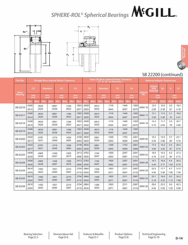
Part No. Straight Bore Internal Radial Clearance Taper (K) Bore Internal Radial Clearance (1” in 12” on Diameter ) Optional Adapter Dimensions
Base Bearing
C2 Standard C3 C4 C2 Standard C3 C4
Adapter No.
Adapter Shaft
DimensionB1 S D1
mm inch
mm inch
mm inch
mm inch
mm inch
mm inch
mm inch
mm inch
mm inch
mm inch
Min Max Min Max Min Max Min Max Min Max Min Max Min Max Min Max (Ref) (Ref) (Ref) (Ref)
SB-22216.0356 .0635
.0025.0991.0039
.1346
.0053.1803 .0508 .0813
.0032.1118 .1448 .1905
SNW 1612.0 10.6 3.0 18.5
.0014 .0071 .0020 .0044 .0057 .0075 2.69 2.38 .67 4.16
SB-22217.0356 .0635
.0025.0991.0039
.1346
.0053.1803 .0508 .0813
.0032.1118 .1448 .1905
SNW 1713.1 11.0 3.1 19.6
.0014 .0071 .0020 .0044 .0057 .0075 2.94 2.48 .70 4.41
SB-22218.0356 .0635
.0025.0991.0039
.1346
.0053.1803 .0508 .0813
.0032.1118 .1448 .1905
SNW 1814.2 11.7 3.5 20.7
.0014 .0071 .0020 .0044 .0057 .0075 3.19 2.64 .78 4.66
SB-22219.0356 .0635
.0025.0991.0039
.1346
.0053.1803 .0508 .0813
.0032.1118.0044
.1448 .1905- - - - -
.0014 .0071 .0020 .0057 .0075
SB-22220.0432 .0787
.0031.1219.0048
.1626
.0064.2108 .0635 .0991
.0039.1346 .1753 .2261
SNW 2015.3 12.8 3.7 23.1
.0017 .0083 .0025 .0053 .0069 .0089 3.44 2.88 .84 5.19
SB-22222.0432 .0787
.0031.1219.0048
.1626
.0064.2108 .0635 .0991
.0039.1346 .1753 .2261
SNW 2217.5 14.2 4.0 25.4
.0017 .0083 .0025 .0053 .0069 .0089 3.94 3.20 .91 5.72
SB-22224.0508 .0965
.0038.1448.0057
.1905
.0075.2413 .0762 .1194
.0047.1600 .2057 .2591
SNW 2418.6 15.4 4.2 27.3
.0020 .0095 .0030 .0063 .0081 .0102 4.19 3.47 .94 6.13
SB-22226.0508 .0965
.0038.1448.0057
.1905
.0075.2413 .0762 .1194
.0047.1600 .2057 .2591
SNW 2619.7 16.8 4.4 30.0
.0020 .0095 .0030 .0063 .0081 .0102 4.44 3.77 1.00 6.75
SB-22228.0610 .1092
.0043.1651.0065
.2210
.0087.2794 .0864 .1346
.0053.1803 .2311 .2997
SNW 2822.0 17.7 4.7 31.5
.0024 .0110 .0034 .0071 .0091 .0118 4.94 3.98 1.06 7.09
SB-22230.0610 .1092
.0043.1651.0065
.2210
.0087.2794 .0864 .1346
.0053.1803 .2311 .2997
SNW 3023.1 18.8 5.0 34.2
.0024 .0110 .0034 .0071 .0091 .0118 5.19 4.23 1.13 7.69
SB-22236.0610 .1092
.0043.1651.0065
.2210
.0087.2794 .0864 .1346
.0053.1803 .2311 .2997
SNW 3628.6 22.5 5.6 40.3
.0024 .0110 .0034 .0071 .0091 .0118 6.44 5.05 1.25 9.06
BsBDsD
J
HG
W
Ro
Ri
SB 22200 (continued)
Bearing SelectionPage D-3
Nomenclature AidPage D-6
����� ���7�Y���]��Page D-7
Product OptionsPage D-8
Technical EngineeringPage D-19
SPHERE-ROL® Spherical Bearings
D-15
Sph
ere
-Ro
l B
ea
rin
gs
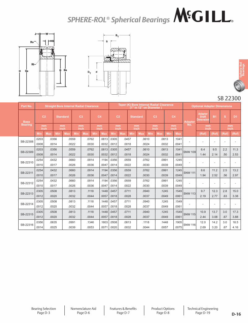
SB 22300
D BsBDs
HG
W
r
r
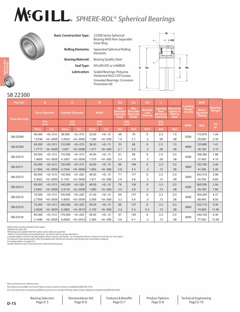
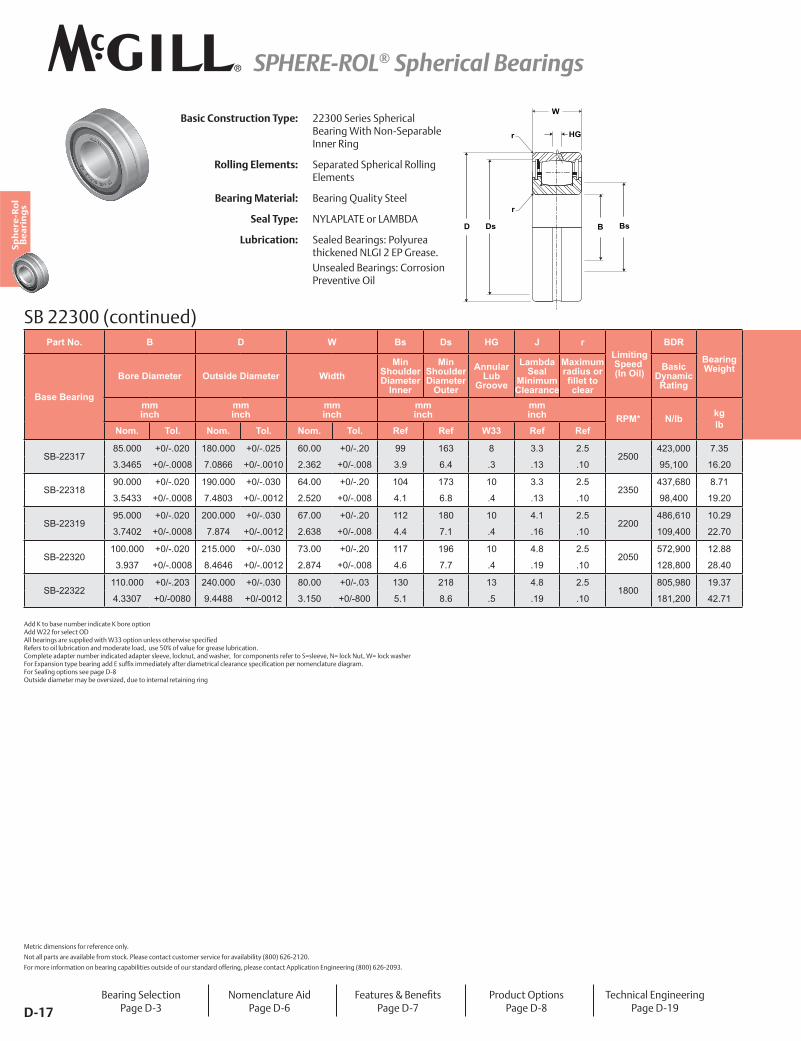
Basic Construction Type: 22300 Series Spherical Bearing With Non-Separable Inner Ring
Rolling Elements: Separated Spherical Rolling Elements
Bearing Material: Bearing Quality Steel
Seal Type: NYLAPLATE or LAMBDA
Lubrication: Sealed Bearings: Polyurea thickened NLGI 2 EP Grease.Unsealed Bearings: Corrosion Preventive Oil
Add K to base number indicate K bore option Add W22 for select OD ����"�� ����� �����������!�����;;���������������� !���������]�� *Refers to oil lubrication and moderate load, use 50% of value for grease lubrication. Complete adapter number indicated adapter sleeve, locknut, and washer, for components refer to S=sleeve, N= lock Nut, W= lock washer � ��H��������'���"�� �����������@]H�����������'��@�� ������� ��������� ����������]�������� ���������� ����� ��< For Sealing options see page D-8 Outside diameter may be oversized, due to internal retaining ring
Part No. B D W Bs Ds HG J r Limiting
Speed (In Oil)
BDR
Bearing Weight
Base Bearing
Bore Diameter Outside Diameter WidthMin
Shoulder Diameter
Inner
Min Shoulder Diameter
Outer
Annular Lub
Groove
Lambda Seal
Minimum Clearance
Maximum radius or �������clear
Basic Dynamic Rating
mm inch
mm inch
mm inch
mm inch
mm inch RPM* N/lb kg
lbNom. Tol. Nom. Tol. Nom. Tol. Ref Ref W33 Ref Ref
SB-2230840.000 +0/-.013 90.000 +0/-.015 33.00 +0/-.13 48 79 5 2.3 1.5
5250113,870 1.04
1.5748 +0/-.0005 3.5433 +0/-.0006 1.299 +0/-.005 1.9 3.1 .2 .09 .06 25,600 2.30
SB-2230945.000 +0/-.013 110.000 +0/-.015 36.00 +0/-.13 53 89 8 2.3 1.5
4650133,880 1.41
1.7717 +0/-.0005 3.937 +0/-.0006 1.417 +0/-.005 2.1 3.5 .3 .09 .06 30,100 3.10
SB-2231050.000 +0/-.013 110.000 +0/-.015 40.00 +0/-.13 61 99 8 2.3 2.0
4200166,360 1.86
1.9685 +0/-.0005 4.3307 +0/-.0006 1.575 +0/-.005 2.4 3.9 .3 .09 .08 37,400 4.10
SB-2231155.000 +0/-.013 120.000 +0/-.015 43.00 +0/-.15 66 109 8 3.3 2.0
3800183,700 2.40
2.1654 +0/-.0005 4.7244 +0/-.0006 1.693 +0/-.006 2.6 4.3 .3 .13 .08 41,300 5.30
SB-2231260.000 +0/-.013 130.000 +0/-.020 46.00 +0/-.15 71 117 8 3.3 2.0
3500243,310 2.99
2.3622 +0/-.0005 5.1181 +0/-.0008 1.811 +0/-.006 2.8 4.6 .3 .13 .08 54,700 6.60
SB-2231365.000 +0/-.013 140.000 +0/-.020 48.00 +0/-.15 76 124 8 3.3 2.0
3250265,550 3.54
2.5591 +0/-.0005 5.5118 +0/-.0008 1.890 +0/-.006 3.0 4.9 .3 .13 .08 59,700 7.80
SB-2231470.000 +0/-.013 150.000 +0/-.020 51.00 +0/-.15 84 137 8 3.3 2.0
3000304,240 4.31
2.7559 +0/-.0005 5.9055 +0/-.0008 2.008 +0/-.006 3.3 5.4 .3 .13 .08 68,400 9.50
SB-2231575.000 +0/-.013 160.000 +0/-.025 55.00 +0/-.15 86 137 8 3.3 2.0
2800332,710 5.39
2.9528 +0/-.0005 6.2992 +0/-.0010 2.165 +0/-.006 3.4 5.4 0.3 .13 .08 74,800 11.90
SB-2231680.000 +0/-.013 170.000 +0/-.025 58.00 +0/-.15 91 155 8 3.3 2.0
2650344,720 6.30
3.1496 +0/-.0005 6.6929 +0/-.0010 2.284 +0/-.006 3.6 6.1 .3 .13 .08 77,500 13.90
Metric dimensions for reference only.
Not all parts are available from stock. Please contact customer service for availability (800) 626-2120.
For more information on bearing capabilities outside of our standard offering, please contact Application Engineering (800) 626-2093.
Bearing SelectionPage D-3
Nomenclature AidPage D-6
����� ���7�Y���]��Page D-7
Product OptionsPage D-8
Technical EngineeringPage D-19
SPHERE-ROL® Spherical Bearings
D-16
Sph
ere
-Ro
l B
ea
rin
gs
dD1
B
S
1
Part No. Straight Bore Internal Radial Clearance Taper (K) Bore Internal Radial Clearance (1” in 12” on Diameter ) Optional Adapter Dimensions
Base Bearing
C2 Standard C3 C4 C2 Standard C3 C4
Adapter No.
Adapter Shaft
DimensionB1 S D1
mm inch
mm inch
mm inch
mm inch
mm inch
mm inch
mm inch
mm inch
mm inch
mm inch
Min Max Min Max Min Max Min Max Min Max Min Max Min Max Min Max (Ref) (Ref) (Ref) (Ref)
SB-22308.0203 .0356 .0559 .0762 .0813 .0305 .0457 .0610 .0813 .1041
- - - - -.0008 .0014 .0022 .0030 .0032 .0012 .0018 .0024 .0032 .0041
SB-22309.0203 .0356 .0559 .0762 .0813 .0305 .0457 .0610 .0813 .1041
SNW 1096.4 9.5 2.2 11.3
.0008 .0014 .0022 .0030 .0032 .0012 .0018 .0024 .0032 .0041 1.44 2.14 .50 2.53
SB-22310.0254 .0432 .0660 .0914 .1194 .0356 .0559 .0762 .0991 .1245
- - - - -.0010 .0017 .0026 .0036 .0047 .0014 .0022 .0030 .0039 .0049
SB-22311.0254 .0432 .0660 .0914 .1194 .0356 .0559 .0762 .0991 .1245
SNW 1118.6 11.2 2.5 13.2
.0010 .0017 .0026 .0036 .0047 .0014 .0022 .0030 .0039 .0049 1.94 2.52 .56 2.97
SB-22312.0254 .0432 .0660 .0914 .1194 .0356 .0559 .0762 .0991 .1245
- - - - -.0010 .0017 .0026 .0036 .0047 .0014 .0022 .0030 .0039 .0049
SB-22313.0305 .0508 .0813 .1118 .1448 .0457 .0711 .0940 .1245 .1549
SNW 1139.7 12.3 2.8 15.0
.0012 .0020 .0032 .0044 .0057 .0018 .0028 .0037 .0049 .0061 2.19 2.77 .63 3.38
SB-22314.0305 .0508 .0813 .1118 .1448 .0457 .0711 .0940 .1245 .1549
- - - - -.0012 .0020 .0032 .0044 .0057 .0018 .0028 .0037 .0049 .0061
SB-22315.0305 .0508 .0813 .1118 .1448 .0457 .0711 .0940 .1245 .1549
SNW 11510.9 13.7 3.0 17.3
.0012 .0020 .0032 .0044 .0057 .0018 .0028 .0037 .0049 .0061 2.44 3.08 .67 3.88
SB-22316.0356 .0635 .0991 .1346 .1803 .0508 .0813 .1118 .1448 .1905
SNW 11612.0 14.2 3.0 18.5
.0014 .0025 .0039 .0053 .0071 .0020 .0032 .0044 .0057 .0075 2.69 3.20 .67 4.16
BsBDsD
J
HG
W
Ro
Ri
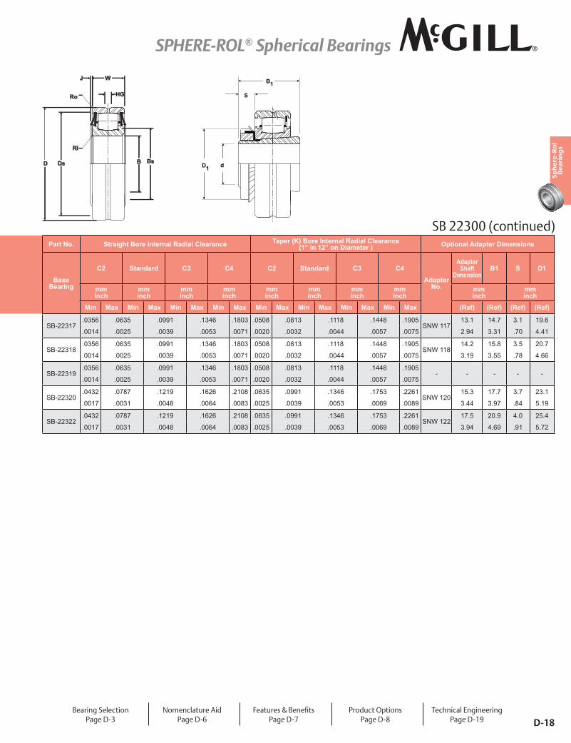
SB 22300
Bearing SelectionPage D-3
Nomenclature AidPage D-6
����� ���7�Y���]��Page D-7
Product OptionsPage D-8
Technical EngineeringPage D-19
SPHERE-ROL® Spherical Bearings
D-17
Sph
ere
-Ro
l B
ea
rin
gs
Part No. B D W Bs Ds HG J r Limiting
Speed (In Oil)
BDR
Bearing Weight
Base Bearing
Bore Diameter Outside Diameter WidthMin
Shoulder Diameter
Inner
Min Shoulder Diameter
Outer
Annular Lub
Groove
Lambda Seal
Minimum Clearance
Maximum radius or �������clear
Basic Dynamic Rating
mm inch
mm inch
mm inch
mm inch
mm inch RPM* N/lb kg
lbNom. Tol. Nom. Tol. Nom. Tol. Ref Ref W33 Ref Ref
SB-2231785.000 +0/-.020 180.000 +0/-.025 60.00 +0/-.20 99 163 8 3.3 2.5
2500423,000 7.35
3.3465 +0/-.0008 7.0866 +0/-.0010 2.362 +0/-.008 3.9 6.4 .3 .13 .10 95,100 16.20
SB-2231890.000 +0/-.020 190.000 +0/-.030 64.00 +0/-.20 104 173 10 3.3 2.5
2350437,680 8.71
3.5433 +0/-.0008 7.4803 +0/-.0012 2.520 +0/-.008 4.1 6.8 .4 .13 .10 98,400 19.20
SB-2231995.000 +0/-.020 200.000 +0/-.030 67.00 +0/-.20 112 180 10 4.1 2.5
2200486,610 10.29
3.7402 +0/-.0008 7.874 +0/-.0012 2.638 +0/-.008 4.4 7.1 .4 .16 .10 109,400 22.70
SB-22320100.000 +0/-.020 215.000 +0/-.030 73.00 +0/-.20 117 196 10 4.8 2.5
2050572,900 12.88
3.937 +0/-.0008 8.4646 +0/-.0012 2.874 +0/-.008 4.6 7.7 .4 .19 .10 128,800 28.40
SB-22322110.000 +0/-.203 240.000 +0/-.030 80.00 +0/-.03 130 218 13 4.8 2.5
1800805,980 19.37
4.3307 +0/-0080 9.4488 +0/-0012 3.150 +0/-800 5.1 8.6 .5 .19 .10 181,200 42.71
SB 22300 (continued)
D BsBDs
HG
W
r
r
Basic Construction Type: 22300 Series Spherical Bearing With Non-Separable Inner Ring
Rolling Elements: Separated Spherical Rolling Elements
Bearing Material: Bearing Quality Steel
Seal Type: NYLAPLATE or LAMBDA
Lubrication: Sealed Bearings: Polyurea thickened NLGI 2 EP Grease.Unsealed Bearings: Corrosion Preventive Oil
Add K to base number indicate K bore option Add W22 for select OD ����"�� ����� �����������!�����;;���������������� !���������]�� Refers to oil lubrication and moderate load, use 50% of value for grease lubrication. Complete adapter number indicated adapter sleeve, locknut, and washer, for components refer to S=sleeve, N= lock Nut, W= lock washer � ��H��������'���"�� �����������@]H�����������'��@�� ������� ��������� ����������]�������� ���������� ����� ��< For Sealing options see page D-8 Outside diameter may be oversized, due to internal retaining ring
Metric dimensions for reference only.
Not all parts are available from stock. Please contact customer service for availability (800) 626-2120.
For more information on bearing capabilities outside of our standard offering, please contact Application Engineering (800) 626-2093.
Bearing SelectionPage D-3
Nomenclature AidPage D-6
����� ���7�Y���]��Page D-7
Product OptionsPage D-8
Technical EngineeringPage D-19
SPHERE-ROL® Spherical Bearings
D-18
Sph
ere
-Ro
l B
ea
rin
gs
Part No. Straight Bore Internal Radial Clearance Taper (K) Bore Internal Radial Clearance (1” in 12” on Diameter ) Optional Adapter Dimensions
Base Bearing
C2 Standard C3 C4 C2 Standard C3 C4
Adapter No.
Adapter Shaft
DimensionB1 S D1
mm inch
mm inch
mm inch
mm inch
mm inch
mm inch
mm inch
mm inch
mm inch
mm inch
Min Max Min Max Min Max Min Max Min Max Min Max Min Max Min Max (Ref) (Ref) (Ref) (Ref)
SB-22317.0356 .0635 .0991 .1346 .1803 .0508 .0813 .1118 .1448 .1905
SNW 11713.1 14.7 3.1 19.6
.0014 .0025 .0039 .0053 .0071 .0020 .0032 .0044 .0057 .0075 2.94 3.31 .70 4.41
SB-22318.0356 .0635 .0991 .1346 .1803 .0508 .0813 .1118 .1448 .1905
SNW 11814.2 15.8 3.5 20.7
.0014 .0025 .0039 .0053 .0071 .0020 .0032 .0044 .0057 .0075 3.19 3.55 .78 4.66
SB-22319.0356 .0635 .0991 .1346 .1803 .0508 .0813 .1118 .1448 .1905
- - - - -.0014 .0025 .0039 .0053 .0071 .0020 .0032 .0044 .0057 .0075
SB-22320.0432 .0787 .1219 .1626 .2108 .0635 .0991 .1346 .1753 .2261
SNW 12015.3 17.7 3.7 23.1
.0017 .0031 .0048 .0064 .0083 .0025 .0039 .0053 .0069 .0089 3.44 3.97 .84 5.19
SB-22322.0432 .0787 .1219 .1626 .2108 .0635 .0991 .1346 .1753 .2261
SNW 12217.5 20.9 4.0 25.4
.0017 .0031 .0048 .0064 .0083 .0025 .0039 .0053 .0069 .0089 3.94 4.69 .91 5.72
dD1
B
S
1
BsBDsD
J
HG
W
Ro
Ri
SB 22300 (continued)
Bearing SelectionPage D-3
Nomenclature AidPage D-6
����� ���7�Y���]��Page D-7
Product OptionsPage D-8
Technical EngineeringPage D-19
SPHERE-ROL® Spherical Bearings
D-19
Sph
ere
-Ro
l B
ea
rin
gs
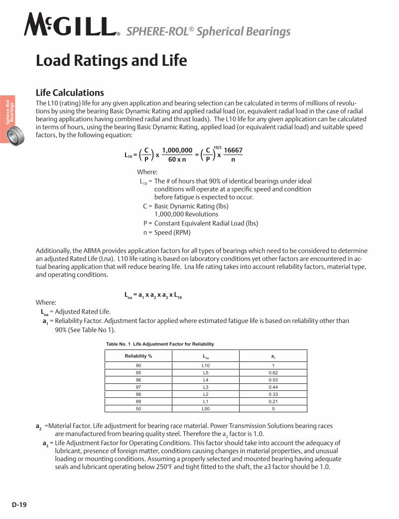
Load Ratings and Life
Life CalculationsThe L10 (rating) life for any given application and bearing selection can be calculated in terms of millions of revolu-tions by using the bearing Basic Dynamic Rating and applied radial load (or, equivalent radial load in the case of radial bearing applications having combined radial and thrust loads). The L10 life for any given application can be calculated in terms of hours, using the bearing Basic Dynamic Rating, applied load (or equivalent radial load) and suitable speed factors, by the following equation:
L10 = x = x
Where: L10 = The # of hours that 90% of identical bearings under ideal � � � � � ���������!������ ��������������]�������������������� before fatigue is expected to occur. C = Basic Dynamic Rating (lbs) 1,000,000 Revolutions P = Constant Equivalent Radial Load (lbs) n = Speed (RPM)
Additionally, the ABMA provides application factors for all types of bearings which need to be considered to determine an adjusted Rated Life (Lna). L10 life rating is based on laboratory conditions yet other factors are encountered in ac-tual bearing application that will reduce bearing life. Lna life rating takes into account reliability factors, material type, and operating conditions.
Lna = a1 x a2 x a3 x L10 Where: Lna = Adjusted Rated Life. a1 = Reliability Factor. Adjustment factor applied where estimated fatigue life is based on reliability other than 90% (See Table No 1).
a2 = Material Factor. Life adjustment for bearing race material. Power Transmission Solutions bearing races are manufactured from bearing quality steel. Therefore the a2 factor is 1.0. a3 = Life Adjustment Factor for Operating Conditions. This factor should take into account the adequacy of lubricant, presence of foreign matter, conditions causing changes in material properties, and unusual loading or mounting conditions. Assuming a properly selected and mounted bearing having adequate � � � ������������" �������� �����"��!�Z=~������������]��������������@��������;�@��� �������"���<~<
Table No. 1 Life Adjustment Factor for Reliability
Reliability % Lna a1
90 L10 195 L5 0.6296 L4 0.5397 L3 0.4498 L2 0.3399 L1 0.2150 L50 5
CP( ) C
P( )1,000,00060 x n
16667n
10/3
SPHERE-ROL® Spherical Bearings
D-20
Sph
ere
-Ro
l B
ea
rin
gs
Load Ratings and Life Continued
Vibration and shock loading can act as an additional loading to the steady expected applied load. When shock or vibration is present, an a3 Life Adjustment Factor can be applied. Shock loading has many variables which often are not easily determined. Typically, it is best to rely on one’s experience with the particular application. Consult Ap-plication Engineering for assistance with applications involving shock or vibration loading.
The a3 factor takes into account a wide range of application and mounting conditions as well as bearing features ���������<����� �������� ��������@������@��� ����� ����'������*����� ����������������#]�����H�� �����<�Power Transmission Solutions offers a wide range of options which can maximize bearing performance. Consult Application Engineering for more information.
Combined Load – Single Row Spherical Roller Bearings1. Calculate Fa/Fr.� ��������� ���~<�Z�����¯��� � ��������� �±�~<�Z�����¯�~<{�� �²�=<~��
P = Equivalent radial load, lbs. Fr = Applied radial load, lbs. Fa = Applied thrust load, lbs. V = Rotation factor = 1.0 for most applications = 1.2 for vibratory applications
For applications involving combination loads in which Fa/Fr > 0.20, consult Application Engineering.
2. Calculate the L10 life using the life equation on page D-19.
SPHERE-ROL® Spherical Bearings
D-21
Sph
ere
-Ro
l B
ea
rin
gs
Load Ratings and Life Continued
Variable Load FormulaRoot mean load (RML) is to be used when a number of varying loads are applied to a bearing for varying time limits. Maximum loading still must be considered for bearing size selection. RML* =
Where: RML = Root Mean Load (lbs.) L1, L2, etc. = Load in pounds N1, N2, etc. = Percent of total time operated at loads L1, L2, etc.
* Apply RML to rating at mean speed to determine resultant life.
Mean Speed FormulaThe following formula is to be used when operating speed varies over time.
Bearing Life In Oscillating ApplicationsThe equivalent rotative speed (ERS) is used in life calculations when the bearing does not make complete revolu-tions during operation. The ERS is then used as the bearing operating speed in the calculation of the L10 (Rating) $�@�<������@ ��������"���������@]����������� � ����������*�� ��� �������*� ���<��
ERS = Equivalent Rotative Speed N = Total number of degrees per minute through which the bearing will rotate. ERS =
In the above formula, allowance is made for the total number of stress applications on the weakest race per unit time, which, in turn, determines fatigue life and the speed factors. The theory behind fretting corrosion is best explained by the fact that the rolling elements in small angles of oscillation retrace a path over an unchanging area @��������� � ���� � �����!�� ��������" ���������� �*������"'���� ����@ ��`!������"���������� ��� ��������"�� -ing oscillates in one direction. Upon reversal, this small area of rolling contact is traversed by the same roller in the dry state. The friction of the two unlubricated surfaces causes fretting corrosion and produces failures which are unpredictable from a normal life standpoint.
S1N1 + S2N2 + S3N3
100Mean Speed =
S1S2, etc = Speeds in RPM N1N2, etc = Percentage of total time operated at speeds S1S2, etc
N360
(L110/3 N1) + (L2
10/3 N2) + (L310/3 N3)
100
10/3
SPHERE-ROL® Spherical Bearings
D-22
Sph
ere
-Ro
l B
ea
rin
gs
Load Ratings and Life Continued
With a given bearing selected for an oscillating application, the best lubrication means is a light mineral oil under �����*��`!���������<�������������������� ��������������'�@ ������ �����������"�� �������������"������ ���������" ������������������<�����@����`!���" �����������������������'�H����������� ����!�������'�@ ���������������'��� ����away by the lubricant, and since these oxides are abrasive, further wear tends to be avoided. If grease lubrication must be used, it is best to consult with either the bearing manufacturer or the lubricant manufacturer to determine the best possible type of lubricant. Greases have been compounded to resist the detrimental effect of fretting corrosion for such applications.
Minimum Bearing LoadSkidding, or sliding, of the rolling elements on the raceway instead of a true rolling motion can cause excessive wear. Applications with high speeds and light loading are particularly prone to skidding. As a general guideline, rolling ele-ment bearings should be radially loaded at least 2% of Basic Dynamic Rating. For applications where load is light relative to the bearings dynamic load rating, consult Application Engineering for assistance.
SPHERE-ROL® Spherical Bearings
D-23
Sph
ere
-Ro
l B
ea
rin
gs
Spherical Engineering Section
Equivalent LoadsWhen SPHERE-ROL® bearings operate under conditions of combined radial and thrust loads, an equivalent radial load must be calculated to determine resultant bearing life. SPHERE-ROL® bearings are not recommended for ��������������*�*����� ���� �����������!�*� ����"��������������'�"���� ���������� ������!��������following equivalent radial load formulae:
P = Equiv. radial load, lbs.Fr = Applied radial load, lbs.Fa = Applied thrust load, lbs.V = Rotation factor= 1.0 for most applications= 1.2 for vibratory applicationsFor applications involving combination loads in which Fa/Fr > .20, consult Application Engineering.
Static Load Rating����¢����������� ����¢������������@ ��'����� �"������������ ������"�� �������!������ ����������H������������stress of 580,000 PSI, acting at the center of contact of the most heavily loaded rolling element. At this stress level, ����������@ ������"�����_ �"�������"������]����|<��H�� ������������!���������������������@ ��������������stress level can be tolerated in most bearing applications without impairment of subsequent bearing operation. In certain applications where subsequent rotation of the bearing is slow and where smoothness and friction requirements are not too exacting, a higher static load limit can be tolerated. Where extreme smoothness is required or friction requirements are critical, a lower static load limit may be necessary. ������������"�� ����� ����"���������"��� ������������ ������������������*������������� ���������������]������� PO = 0.5 Fr + 4.0 Fa orPO = Fr whichever is greater. ������������������������ ���@ ������]������������� �������������������������*�*����� ����������� ��������<
When Fa
Fr<_ 0.12; P = VFr
When Fa
Fr< 0.12; P = .4VFr + 5.0 Fa
SPHERE-ROL® Spherical Bearings
D-24
Sph
ere
-Ro
l B
ea
rin
gs
Spherical Engineering Section continued
Matched BearingsWhere bearings are mounted so that the distance between them is less than the width of one bearing, it is recommended under heavy loading conditions to provide some degree of diametral matching in order to prevent unequal sharing of the applied load. Matching procedures have been developed to provide super precision matching of bearings. Y�� ������������������������ '�� ��������]���"'�¢#��¢���@]H�@ ����� �� ������< A. O.D. and I.D., where applicable, of matched bearings same diameters within 30% of the respective O.D. or I.D. tolerance.B. Diametral clearance, where applicable, of matched bearings same within 30% of the tolerance range.C. Radial runout of matched bearings same within 20% of the tolerance range.D. High point of radial runout marked on the face of each outer and inner ring.E. Matched bearings are packaged as a unit.
Multiply Matching Factor by rating of single bearing to obtain resultant rating for pair of bearings.
Diametral ClearanceSPHERE-ROL®�"�� ����� ���*����"������@� ����� ���������� ������� ����� �����������]�������Z�������� ����;������{<�The C2 internal diametral clearance is less than the Standard, while C3 and C4 are progressively looser than Standard. Similarly, four internal clearance ranges are available for tapered bore SPHERE-ROL® bearings. Each of these ranges is somewhat looser than the corresponding cylindrical bore bearing internal diametral clearance range, because of the ����������������������!��������� �]��!������������ ���" ���������� �������< The two charts below give the internal diametral clearance ranges normally available with SPHERE-ROL® bearings Y�� ������*��������� �������� ������� �����!�������"��������]���"'����������� N�����!�*� �������Z���;������{����� ������!����"��������]���������"�� ������� � ���@�����@��!�������"�����"�� ������"� <�������������� �Service for availability on non-standard diametral clearances.
Matching Factor �������������1.55 None1.71 “-DS”
SPHERE-ROL® Spherical Bearings
D-25
Sph
ere
-Ro
l B
ea
rin
gs
Spherical Engineering Section continued
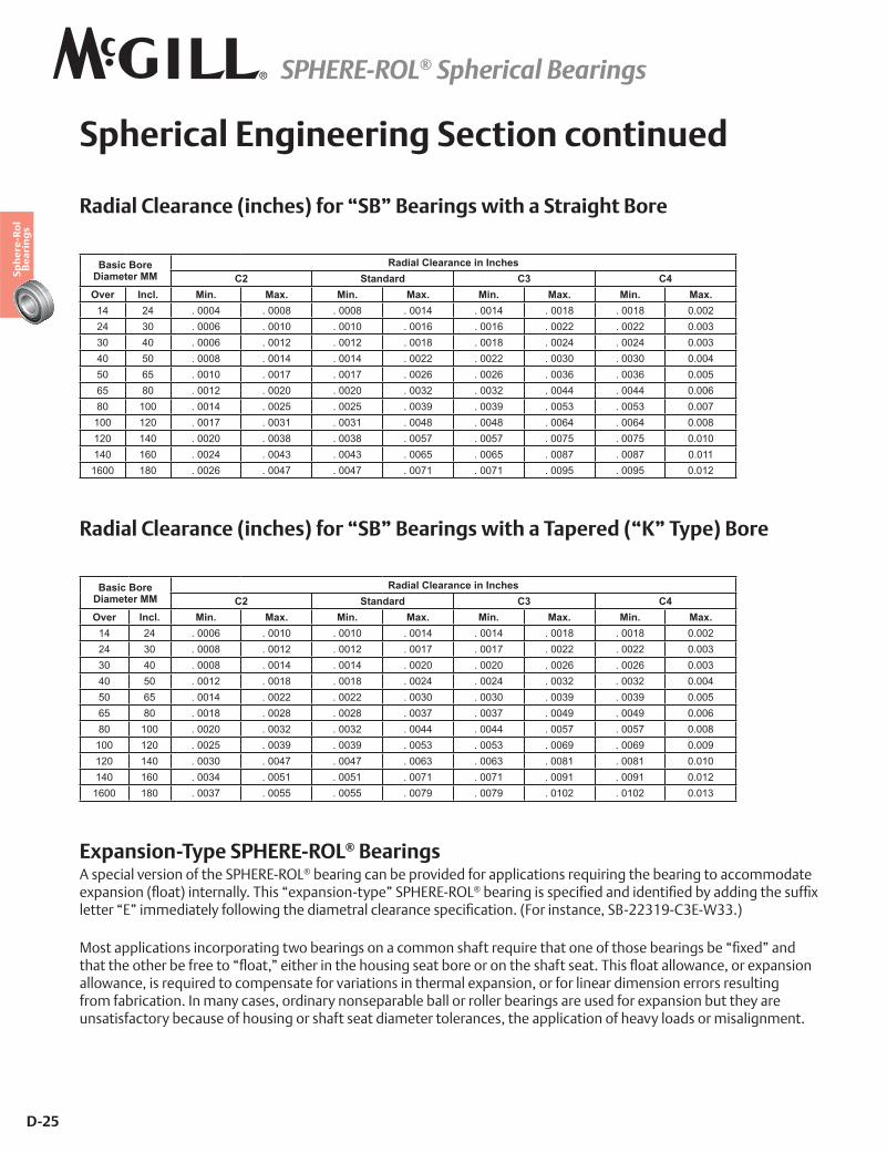
Radial Clearance (inches) for “SB” Bearings with a Straight Bore
Basic Bore Diameter MM
Radial Clearance in InchesC2 Standard C3 C4
Over Incl. Min. Max. Min. Max. Min. Max. Min. Max.14 24 . 0004 . 0008 . 0008 . 0014 . 0014 . 0018 . 0018 0.00224 30 . 0006 . 0010 . 0010 . 0016 . 0016 . 0022 . 0022 0.00330 40 . 0006 . 0012 . 0012 . 0018 . 0018 . 0024 . 0024 0.00340 50 . 0008 . 0014 . 0014 . 0022 . 0022 . 0030 . 0030 0.00450 65 . 0010 . 0017 . 0017 . 0026 . 0026 . 0036 . 0036 0.00565 80 . 0012 . 0020 . 0020 . 0032 . 0032 . 0044 . 0044 0.00680 100 . 0014 . 0025 . 0025 . 0039 . 0039 . 0053 . 0053 0.007
100 120 . 0017 . 0031 . 0031 . 0048 . 0048 . 0064 . 0064 0.008120 140 . 0020 . 0038 . 0038 . 0057 . 0057 . 0075 . 0075 0.010140 160 . 0024 . 0043 . 0043 . 0065 . 0065 . 0087 . 0087 0.011
1600 180 . 0026 . 0047 . 0047 . 0071 . 0071 . 0095 . 0095 0.012
Basic Bore Diameter MM
Radial Clearance in InchesC2 Standard C3 C4
Over Incl. Min. Max. Min. Max. Min. Max. Min. Max.14 24 . 0006 . 0010 . 0010 . 0014 . 0014 . 0018 . 0018 0.00224 30 . 0008 . 0012 . 0012 . 0017 . 0017 . 0022 . 0022 0.00330 40 . 0008 . 0014 . 0014 . 0020 . 0020 . 0026 . 0026 0.00340 50 . 0012 . 0018 . 0018 . 0024 . 0024 . 0032 . 0032 0.00450 65 . 0014 . 0022 . 0022 . 0030 . 0030 . 0039 . 0039 0.00565 80 . 0018 . 0028 . 0028 . 0037 . 0037 . 0049 . 0049 0.00680 100 . 0020 . 0032 . 0032 . 0044 . 0044 . 0057 . 0057 0.008
100 120 . 0025 . 0039 . 0039 . 0053 . 0053 . 0069 . 0069 0.009120 140 . 0030 . 0047 . 0047 . 0063 . 0063 . 0081 . 0081 0.010140 160 . 0034 . 0051 . 0051 . 0071 . 0071 . 0091 . 0091 0.012
1600 180 . 0037 . 0055 . 0055 . 0079 . 0079 . 0102 . 0102 0.013
Radial Clearance (inches) for “SB” Bearings with a Tapered (“K” Type) Bore
Expansion-Type SPHERE-ROL® BearingsA special version of the SPHERE-ROL® bearing can be provided for applications requiring the bearing to accommodate �H�������_`��|����� ����'<��������H������#�'������£�+�#+�$®�"�� �����������]�������������]���"'�������������@]H������ ���������������'�@��!������������� ������� ����������]�����<�_� ������������Y#ZZ;�}#�;�#�;;<| X������������������ � ������!�"�� ����������������@�� ���� ����������@������"�� ����"���]H�������������������� �"��@ ������`���������� �������������������" �� ����������@������<������`������!������ ��H�������allowance, is required to compensate for variations in thermal expansion, or for linear dimension errors resulting from fabrication. In many cases, ordinary nonseparable ball or roller bearings are used for expansion but they are unsatisfactory because of housing or shaft seat diameter tolerances, the application of heavy loads or misalignment.
SPHERE-ROL® Spherical Bearings
D-26
Sph
ere
-Ro
l B
ea
rin
gs
Spherical Engineering Section continued
Self-aligning bearings are preferred and the expansion-type SPHERE-ROL® roller bearing is the only internally self-�������"�� ������*�����������"����'�@�������������H������� �`������!��������� ����'< This expansion-type SPHERE-ROL®�"�� �����������������'����� ������"���������@ �������!����¢������ �¢����� ����� ��� �"�� �����"����"�������@��������������� �������� '���������� *������"����������H�������'�@���� ���� ���relative to the other. The expansion allowance in this type SPHERE-ROL® bearing is normally as much as the end play or expansion allowance that would be found in a non-locating cylindrical roller bearing. ����¢�¢��'�����£�+�#+�$® bearing is available with the same sealing advantages, diametral clearance values, tapered " ��������� � ��� ���" �������@���� ������������ ��"�� ������!���������#Z=<�����"������'������ �����@�¢�¢�type SPHERE-ROL® bearings is 10% less than standard SPHERE-ROL® bearings. Maximum seal misalignment is limited due to increased axial play in bearing. The expansion-type SPHERE-ROL® bearing will not operate satisfactorily if subjected to thrust loading. Therefore, the expansion-type SPHERE-ROL®�"�� �����������"����������¢]H��¢�_¢����¢|��������������@ �������'����¢�H������¢�_¢`��¢|��������<������� ����������������������#!���� ��� �����@�"��� ���� ����@������H������#�'���"�� ���"��provided, so that the expansion allowance intended to be available is not lost by error in installation. Expansion-type SPHERE-ROL® bearings are not normally available from stock. Consult Customer Service for availability.
SPHERE-ROL® Spherical Bearings
D-27
Sph
ere
-Ro
l B
ea
rin
gs
Spherical Engineering Section continued
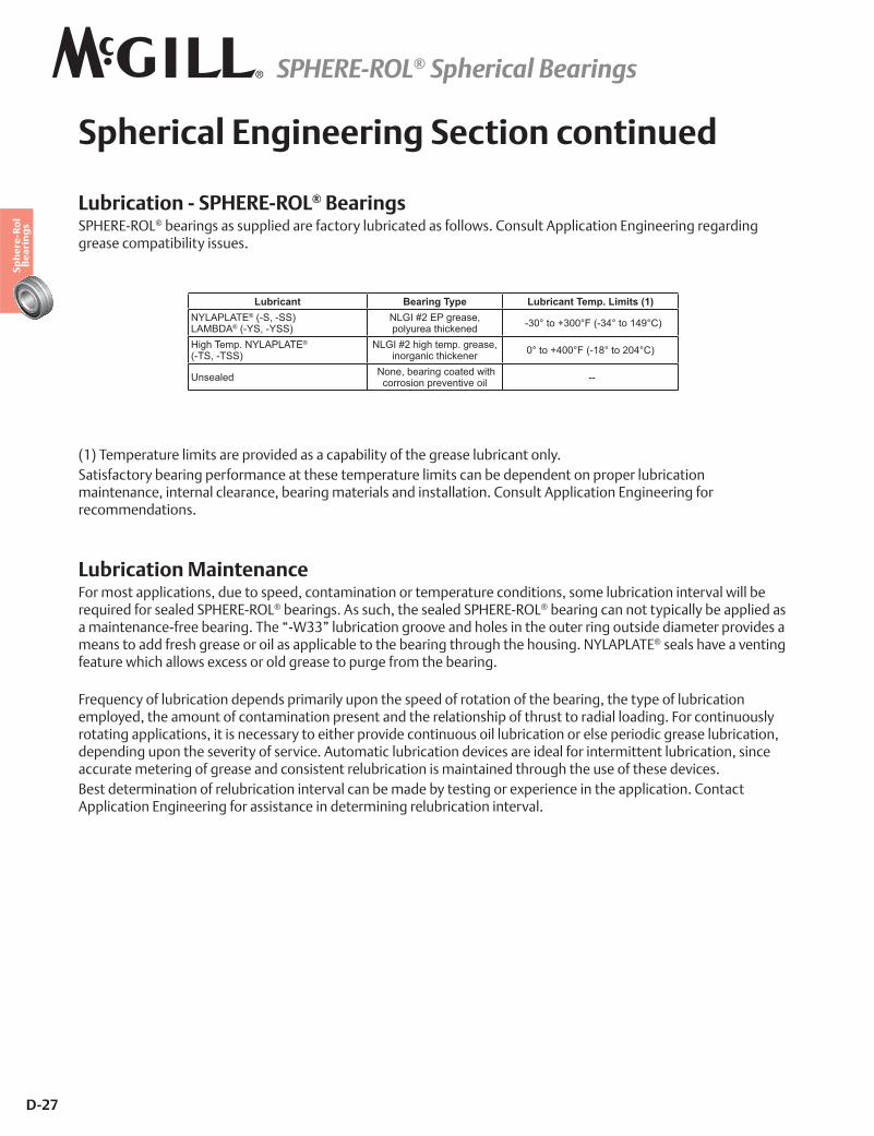
Lubrication - SPHERE-ROL® BearingsSPHERE-ROL® bearings as supplied are factory lubricated as follows. Consult Application Engineering regarding grease compatibility issues.
(1) Temperature limits are provided as a capability of the grease lubricant only.Satisfactory bearing performance at these temperature limits can be dependent on proper lubrication maintenance, internal clearance, bearing materials and installation. Consult Application Engineering for recommendations.
Lubrication MaintenanceFor most applications, due to speed, contamination or temperature conditions, some lubrication interval will be required for sealed SPHERE-ROL® bearings. As such, the sealed SPHERE-ROL® bearing can not typically be applied as a maintenance-free bearing. The “-W33” lubrication groove and holes in the outer ring outside diameter provides a means to add fresh grease or oil as applicable to the bearing through the housing. NYLAPLATE® seals have a venting feature which allows excess or old grease to purge from the bearing. Frequency of lubrication depends primarily upon the speed of rotation of the bearing, the type of lubrication employed, the amount of contamination present and the relationship of thrust to radial loading. For continuously rotating applications, it is necessary to either provide continuous oil lubrication or else periodic grease lubrication, depending upon the severity of service. Automatic lubrication devices are ideal for intermittent lubrication, since accurate metering of grease and consistent relubrication is maintained through the use of these devices.Best determination of relubrication interval can be made by testing or experience in the application. Contact Application Engineering for assistance in determining relubrication interval.
Lubricant Bearing Type Lubricant Temp. Limits (1)NYLAPLATE® (-S, -SS) LAMBDA® (-YS, -YSS)
NLGI #2 EP grease, polyurea thickened -30° to +300°F (-34° to 149°C)
High Temp. NYLAPLATE® (-TS, -TSS)
NLGI #2 high temp. grease, inorganic thickener 0° to +400°F (-18° to 204°C)
Unsealed None, bearing coated with corrosion preventive oil --
SPHERE-ROL® Spherical Bearings
D-28
Sph
ere
-Ro
l B
ea
rin
gs
Spherical Engineering Section continued
Mounting Details - Spherical Roller Bearings Cylindrical BoreProper mounting of SPHERE-ROL®����� ����� ��� �"�� ������� ���'� ���� ������ ����]��@����� ��� ������ �����*�������� ���������<��������������]����������@ ����� ���������� '� �����*�������� ���������<������]�����@������������]��������������� �������*��������� ��� ������������������"����"��!�����@��!�������<�����@��!���� ������general guidelines and details to bear in mind when installing this bearing series. 1. Inspect housing and shaft.
�� Clean, remove burrs and sharp edges.�� If any damage has occurred to the bearing seat in the housing or on the shaft, repair that damage to bring the
seat surface back to its original condition.�� � �������@��]�������� ��� ����'��������<������������������������� ����@����������]����������"������<�� ������������ '���� � ����� �� ���� �����`���_�*���H����'��������������" ��������������@ �
�H������|����������" ���� @����]�����@��=���� �������+����� ���������< 2. Determine which member, shaft or housing has an interference fit with the bearing.
�� ������ �������� ��� ������ �����*�������� ��������������������� @� �����]�<�� +�@� ������@������£����������]����"����@ � �������*��]���������� �����<�� �����������������*� ���"'�
these tables, consult Application Engineering for recommendations. 3. Install the bearing onto the press-fitted member by applying force against the bearing ring that is press-fitted.
�� � ���� ���#]��������� � ��������'�����@ ��� ���� ����������"�������"�� �������������@�������������@����@�the bearing inner ring.
�� � ���� ���#]�������� � ��������'�����@ ��� ���� ����������"�������"�� ����������������������������@����of the bearing outer ring.
�� �� ��������"���H� ������������ �����������"�� ������ ����������� ���#]��������"� �������� ��'��������"��<�� Use arbor press whenever possible.�� Do not hammer on bearing ring face.
4. Inner rings press-fitted on the shaft may be more easily installed by heating the ring and causing it to shrink fit.
�� % ����'������������� ������ª=�����Z�Z���_ª}������~~��|�!����"����@]�����������!����� �����������*� ��������� @� �����]�����@������<
�� Heating the ring should be accomplished with an induction heater or in a mineral oil bath. Never use a torch to heat a bearing for assembly purposes.
�� �������"�� �������������"���������������"����������� �����!����!���������"�� ����� ��]�������'�"��affected.
SPHERE-ROL® Spherical Bearings
D-29
Sph
ere
-Ro
l B
ea
rin
gs
Spherical Engineering Section continued
5. When outer rings are to be press-fitted into a housing, it is desirable to heat the housing to allow it to shrink fit onto the outer ring outside diameter.
�� � ����������"�� ������� ��N����@ ����'������"�'�������� ���#]����������������� ���������<����� �condensation can form inside the bearing upon its return to room temperature, which can lead to corrosion. Exposure to extreme cold can also affect the metallurgical structure of the bearing.
6. Proper caution should be exercised during installation to guard against axial preload of the bearing. This can be checked by:
�� Endplay - Check for endwise “shake” which when present shows that the bearings as installed have endplay.�� Ease of Rotation - Rotate assembly by hand. The bearing must be free from unusual drag or noises.
CAUTION - During installation, do not misalign NYLAPLATE® sealed bearing more than 3° and LAMBDA® sealed bearings more than 1° or seal(s) may be damaged.
Mounting Details - Spherical Roller Bearings Tapered BoreSPHERE-ROL® bearings are available with tapered bore feature for applications utilizing tapered adapter sleeve mounting arrangements or tapered shaft seats. This feature sometimes facilitates the mounting of SPHERE-ROL® bearings and can be used to prevent the necessity for heating of bearings or to eliminate the need for complicated � ����]������ �������<Standard tapered adapter sleeves, as well as associated lock nuts and lock washers, are tabulated on pages D-11 to �#�������� ��������]�"���!����������� � �����"�� ���"'�������@]H����"� <��������� ������������'�"����������������*������'�"'����� ��� �����"� � ����������������� ���" ��"�� ������������������� �!� ����'�"��������]���"'�������@]H������ �¢�¢�@��!�������"�� ������"� <����������� ��" ������ �@�������"�� ��������¢�����Z¢��������������� ���������� ���" ��"�� ����� ���������*���������]���"'�������@]H������ �¢&¢�@��!�������"�����"�� ���number. In mounting, the bearing bore is forced against the taper of the split adapter sleeve or the tapered shaft seat by ����������@�����N����<���� ����*��'������ �]������"��"�������"'����������������N���������� ����������H����displacement of the bearing along the taper. Due to the need for greater take-up of internal clearance with this type of mounting, special internal clearances are provided. Care must be exercised to insure that the optimum take-up of internal clearance is followed. Too great a reduction of internal clearance will result in potential overheating of the bearing in many applications. The mounting procedure for adapter mounted, tapered bore SPHERE-ROL® bearings does not require the use of feeler gauge or special gauging procedure. The basic principle of this measurement system is the use of the lock nut and lock washer as a protractor device. Because the lock nuts available for each basic bearing size are standard ����������'�� ������@���� ����������]���� �����������<������������H������*���������@ ������ �*������@���������is predetermined, and the portions of revolutions of the lock nuts required to obtain the correct internal clearance ���������������� ����� �����<�����������'������������ ����N�!���� ����*���������]�����"� �@������@ ������size, and these tangs can be used as the protractor for determining the correct portions of revolutions of the lock nuts. The basic procedure is as follows:
SPHERE-ROL® Spherical Bearings
D-30
Sph
ere
-Ro
l B
ea
rin
gs
Spherical Engineering Section continued
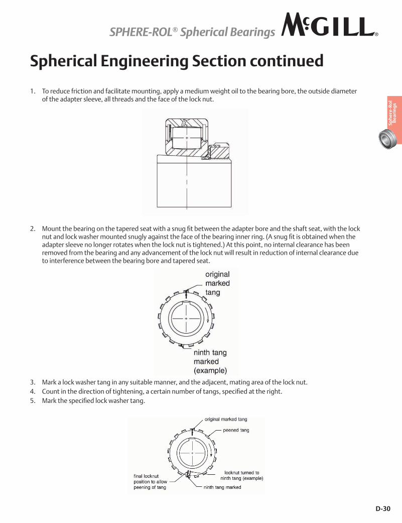
1. To reduce friction and facilitate mounting, apply a medium weight oil to the bearing bore, the outside diameter of the adapter sleeve, all threads and the face of the lock nut.
2. X��������"�� ������������� ��������!����������]��"��!�������������� �" �������������@��������!����������N�����������N�!���� ������������'������������@����@�����"�� ������� � ��<�_������]�����"�������!��������adapter sleeve no longer rotates when the lock nut is tightened.) At this point, no internal clearance has been removed from the bearing and any advancement of the lock nut will result in reduction of internal clearance due to interference between the bearing bore and tapered seat.
3. Mark a lock washer tang in any suitable manner, and the adjacent, mating area of the lock nut.4. �������������� ������@��������������� ��������"� �@������������]���������� ���<5. X� N����������]�����N�!���� ����<
SPHERE-ROL® Spherical Bearings
D-31
Sph
ere
-Ro
l B
ea
rin
gs
Spherical Engineering Section continued
6. Tighten the lock nut until the marked area on the lock nut is in line with the prescribed lock washer tang. (Lightly striking the face of the lock nut with a soft steel bar will reduce thread pressure and make tightening easier.)
7. If, at this point, none of the tangs line up directly with a corresponding slot in the lock nut OD, rotate the lock nut, in a tightening direction, the additional small amount required to line up the closest slot and tang.
8. The correct internal clearance has now been obtained and the lock washer tang can be peened into the slot of the lock nut, thereby locking the assembly.
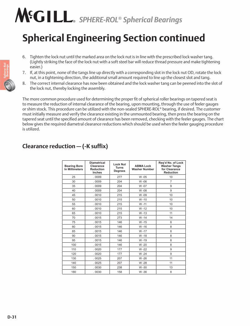
����� �������� ���� �������@ ����� ����������� �� �]��@����� ����� ��� �"�� ���������� �����������to measure the reduction of internal clearance of the bearing, upon mounting, through the use of feeler gauges or shim stock. This procedure can be utilized with the non-sealed SPHERE-ROL® bearing, if desired. The customer must initially measure and verify the clearance existing in the unmounted bearing, then press the bearing on the ���� �����������������������]���������@����� ���������"���� ��*��������N���!��������@���� �����<�������� ��below gives the required diametral clearance reductions which should be used when the feeler gauging procedure is utilized.
Clearance reduction — (-K suffix)
Bearing Bore In Millimeters
Diametrical Clearance Reduction
Inches
Lock Nut Turns
DegreesABMA Lock
Washer Number
Req’d No. of Lock Washer Tangs for Clearance
Reduction25 . 0009 277 W -05 1030 . 0009 204 W -06 735 . 0009 204 W -07 940 . 0009 204 W -08 945 . 0010 215 W -09 1050 . 0010 215 W -10 1055 . 0010 215 W -11 1060 . 0010 215 W -12 1065 . 0010 215 W -13 1170 . 0015 273 W -14 1475 . 0015 146 W -15 880 . 0015 146 W -16 885 . 0015 146 W -17 890 . 0015 146 W -18 895 . 0015 146 W -19 8100 . 0015 146 W -20 8110 . 0020 177 W -22 9120 . 0020 177 W -24 9130 . 0025 207 W -26 11140 . 0025 207 W -28 11150 . 0030 238 W -30 13180 . 0030 158 W -36 8
SPHERE-ROL® Spherical Bearings
D-32
For more information on bearing capabilities outside of our standard offering, please contact Application Engineering (800) 626-2093.
Spherical Bearing Engineering see page D-23.