spicerr ttorsional analysisorsional analysis - oem...
TRANSCRIPT

www.SpicerParts.com©Dana Limited 2014.
Spicer®Spicer®
Torsional AnalysisTorsional AnalysisTorsional Analysis

The Right Angle Makes All the Difference. Correct universal joint operating angles are crucial in preventing torsional and inertial effects, which create vibrations that can damage many of the driveline components in your vehicle. As parts and suspensions wear, driveshaft operating angles often change and therefore require adjustment. In the past, you would have to add or remove shims between the frame and axle, or between the center bearing and cross member. Then you would test drive the vehicle to see if it still vibrated, repeating the process until you eliminated the vibration. The Spicer® Torsional Analysis Calculator enables you to check a vehicle’s driveline installation for torsional and inertia problems, right from your iPad, iPhone, or our website (www.SpicerParts.com). This tutorial will teach you how to use the Spicer Torsional Analysis Calculator to get the best results!
NOTE: The numbers provided throughout this tutorial are examples to be used for demonstration purposes only. You will need to enter your own figures when you use this calculator in real-world applications.

Click on Resouces, then Calculators from the SpicerParts.com home page
Example 1: One-Driveshaft Application
Proceed to the first step
Click the Continue button on the Torsional Analysis information window
Read the Introduction and Torsional Analysis information
The calculator is displayed with data entry controls, additional help features, and five tab buttons along the left side of the calculator window:
Application Information
Side View Angles and Lengths
Side View Driving and Driven Members
Top View Offsets
Results
From the Calculators menu, click Torsional Analysis. The Torsional Analysis Calculator will then load, displaying an information window
Note: All figures used throughout this tutorial are for example purposes only. You will need to input your real-world application data.

Step 1: Enter Application Information
Click Heavy Duty (Class 6-8)on red slider
Proceed to the next step by clicking the Side View Angles and Lengths tab
Click the Driveshaft RPM box Enter 3600 in the box
Click 1 in red box from the Number of Shafts slider
Click the Application Information tab
Example 1: One-Driveshaft Application
Note: All figures used throughout this tutorial are for example purposes only. You will need to input your real-world application data.

Step 2: Enter Side View Angles and Lengths Information
Proceed to the next step by clicking the Side View Driving and Driven Members tab
Click the Side View Angles and Lengths tab
Click the Angle box for Shaft 1Enter 4 in the box
Click the Down (Slope) side of the red slider
Click the Length box for Shaft 1Enter 48 in the box
Note: All figures used throughout this tutorial are for example purposes only. You will need to input your real-world application data.
Example 1: One-Driveshaft Application

Step 3: Enter Side View Driving and Driven Members Information
In this example there are no offsets in the top view, so you can move on to Results
Click to Results
Click the Side View Driving and Driven Members tab
Click the Driving Member Angle boxEnter 7 in the box
Click the Driven Member Angle boxEnter 12 in the box
Click the word Downon red slider Click the word Down on
the red slider
Example 1: One-Driveshaft Application
Note: All figures used throughout this tutorial are for example purposes only. You will need to input your real-world application data.

Note: All figures used throughout this tutorial are for example purposes only. You will need to input your real-world application data.
The numbers provided in this tutorial example are intended to produce bad angles so as to produce the warning page pictured below.
It is important that you read and understand the information produced on this warning page.
It is also important to click the “Click for Details” button and to read and understand the Detail Information before proceeding to the “Reset” button.

Note: All figures used throughout this tutorial are for example purposes only. You will need to input your real-world application data.

Step 5: Re-Enter More Realistic Data Application Information
Proceed to the next step by clicking the Side View Angles and Lengths tab
Example 1: One-Driveshaft Application
Note: All figures used throughout this tutorial are for example purposes only. You will need to input your real-world application data.
Click Heavy Duty (Class 6-8)on red slider
Click the Driveshaft RPM boxEnter 3600 in the box
Click 1 in red box from the Number of Shafts slider
Click the Application Information tab
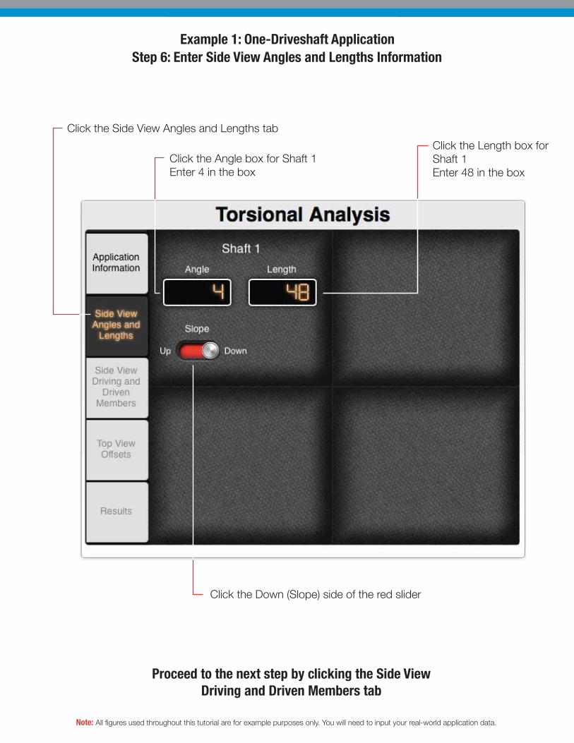
Step 6: Enter Side View Angles and Lengths Information
Proceed to the next step by clicking the Side View Driving and Driven Members tab
Note: All figures used throughout this tutorial are for example purposes only. You will need to input your real-world application data.
Example 1: One-Driveshaft Application
Click the Side View Angles and Lengths tab
Click the Angle box for Shaft 1Enter 4 in the box
Click the Down (Slope) side of the red slider
Click the Length box for Shaft 1Enter 48 in the box

Step 7: Enter Side View Driving and Driven Members Information
In this example there are no offsets in the top view, so you can move on to Results
Click to Results
Click the Side View Driving and Driven Members tab
Click the Driving Member Angle box. Enter 7 in the box
Click the Driven Member Angle box Enter 8 in the box
Click the word Downon red slider
Click the word Down on the red slider
Example 1: One-Driveshaft Application
Note: All figures used throughout this tutorial are for example purposes only. You will need to input your real-world application data.

Step 8: Initial Results
Note that the printing in red, signifying that these values are not acceptable and should be corrected. Look at the results: Torsionals are over our recommended 300 rads/sec and inertias are high on the driven end. That tells us that the operating angle is too high on the driven end of the driveshaft. Let’s go back and shim the driven member to reduce angles.
Look at the information entered and determine how it fits into our suggestions, shown on our introduction page, regarding sizes and cancellation of angles.Here is what the results look like after you do the revised calculation.
7° driver angle minus 4° driveshaft angle = 3° operating angle at the driving end
8° driven angle minus 4° driveshaft angle = 4° operating angle at the driven end
Since the angles are large and unequal, you should expect to see large inertias and large torsional results
Click the Results tab
Example 1: One-Driveshaft Application
Note: All figures used throughout this tutorial are for example purposes only. You will need to input your real-world application data.

Click the Driven Member Angle boxEnter 6(the app will replace the previously entered number)
Click the Side View Driving and Driven Members tab
Click the Results tab again
Here is what the screen looks like after changing the angle of the driven member to 6°.Inertia effects on the driven end came down; more importantly, torsionals came down as well.
Notice the red printing was replaced with white, indicating the results are acceptable.
Step 9: SolutionsExample 1: One-Driveshaft Application
Note: All figures used throughout this tutorial are for example purposes only. You will need to input your real-world application data.

Click the Driven Member Angle boxEnter 7
Click the Side View Driving and Driven Members tab
You could stop at this point, but since this is a learning tool, let’s try one more thing. Let’s purposely make the operating angles on each end of the driveshaft—the angle of the driver and the angle of the driven member—exactly equal: 7°.
Click the Results tab again
Here is what the screen looks like after changing the angle of the driven member to 7˚. Note that torsionals are now 0 (zero). This is because we have the exact same operating angle at each end of our driveshaft, on our driving member and on our driven member. Remember: if the driver and driven members are at the same angle, your torsionals will always be zero.
Proceed to Example 2
Step 10: Equal Operating AnglesExample 1: One-Driveshaft Application
Note: All figures used throughout this tutorial are for example purposes only. You will need to input your real-world application data.

Example 2: Two-Driveshaft ApplicationStep 1: Enter Application Information
Click Light Duty (Class 2-5) from the Application Type slider
Proceed to the next step by clicking the Side View Angles and Lengths tab
Click the Driveshaft RPM boxEnter 3000
Click 2 from the Number of Shafts slider
Click the Application Info button on the Torsional Analysis information window.
To ensure no data remains in the calculator from previous calculation events, always close out of the calculator and the re-open by selecting “Resources,” “Calculator,” “Torsional Analysis.”
Note: All figures used throughout this tutorial are for example purposes only. You will need to input your real-world application data.

Step 2: Enter Side View Angles and Lengths Information
Proceed to the next step by clicking the Side View Driving and Driven Members tab
Click the Side View Angles and Lengths tab
Click the Angle box for Shaft 1 Enter 2
Click the Angle box for Shaft 2Enter 7
Click Down
Click the Length box for Shaft 1Enter 40
Click the Length box for Shaft 2Enter 50
Click Down
Example 2: Two-Driveshaft Application
Note: All figures used throughout this tutorial are for example purposes only. You will need to input your real-world application data.

Click the Side View Driving and Driven Members tab
Step 3: Enter Side View Driving and Driven Members Information
In this example there are no offsets in the top view, so you can move on to Results
Click Results
Click the Driving Member Angle boxEnter 4
Click the Driven Member Angle boxEnter 5
Click Down slider for the Driven Member
Click Down slider for the Driving Member
Example 2: Two-Driveshaft Application
Note: All figures used throughout this tutorial are for example purposes only. You will need to input your real-world application data.

Click the Results tab
Step 4: Initial Results
Proceed to Solution by Clicking Side View Angles and Lengths Tab
The printing is in red to signify that these values are not acceptable and should be corrected
Note that torsionals are high and the inertia effects at the drive end of the shaft are excessive. That should tell you that your angles are not canceled and your operating angle at the drive end of your shaft is probably too large.
Here is what the results look like after you do the initial calculation.
Example 2: Two-Driveshaft Application
Note: All figures used throughout this tutorial are for example purposes only. You will need to input your real-world application data.

We’re going to reduce our operating angles by shimming our center bearing on Shaft 1. this will reduce the angle of Shaft 2, which will reduce the operating angle at our driven member. Click the Shaft 1 Angle box. Enter 3.5
Click the Side View Angles and Lengths tab
Click the Results tab again
Here is what the screen looks like with the Shaft 1 angle changed to 3.5 degrees. Torsionals and inertias are now acceptable.
Step 5: SolutionExample 2: Two-Driveshaft Application
Note: All figures used throughout this tutorial are for example purposes only. You will need to input your real-world application data.

WEB-TORSIONAL-122014 Printed in U.S.A.Copyright Dana Limited, 2014. All rights reserved. Dana Limited.
Dana Aftermarket GroupPO Box 321Toledo, Ohio 43697-0321
Warehouse Distributors: 1.800.621.8084OE Dealers: 1.877.777.5360
www.SpicerParts.com
Tested. Proven. Trusted. Driven. That’s the Spicer Difference. Dana manufactures a wide range of Spicer parts that deliver original equipment quality to the aftermarket. Only Spicer
parts meet the exacting specifications of Dana, the global leader in OE technology.
Talk to your Spicer parts representative today to discover the Spicer difference for yourself.
Automotive Driveshaft Components Automotive Axle Components
Products shown are representative of Spicer and Dana Crate Axle product lines. Additional parts are available.