spiral development: experience, principles, and refinements · for information about purchasing...
TRANSCRIPT
SPECIAL REPORTCMU/SEI-2000-SR-008
Spiral Development:Experience, Principles,and Refinements
Spiral Development WorkshopFebruary 9, 2000
Barry Boehm, edited by Wilfred J. Hansen
July 2000

Pittsburgh, PA 15213-3890
Spiral Development:Experience, Principles,and RefinementsSpiral Development WorkshopFebruary 9, 2000
CMU/SEI-2000-SR-008
Barry Boehm, edited by Wilfred J. Hansen
July 2000
COTS-Based Systems
Unlimited distribution subject to the copyright.
This report was prepared for the
SEI Joint Program OfficeHQ ESC/DIB5 Eglin StreetHanscom AFB, MA 01731-2116
The ideas and findings in this report should not be construed as an official DoD position. It is published in the interest ofscientific and technical information exchange.
FOR THE COMMANDER
Norton L. Compton, Lt Col., USAFSEI Joint Program Office
This work is sponsored by the U.S. Department of Defense. The Software Engineering Institute is afederally funded research and development center sponsored by the U.S. Department of Defense.
Copyright 2000 by Carnegie Mellon University.
NO WARRANTY
THIS CARNEGIE MELLON UNIVERSITY AND SOFTWARE ENGINEERING INSTITUTE MATERIAL ISFURNISHED ON AN “AS-IS” BASIS. CARNEGIE MELLON UNIVERSITY MAKES NO WARRANTIES OF ANYKIND, EITHER EXPRESSED OR IMPLIED, AS TO ANY MATTER INCLUDING, BUT NOT LIMITED TO,WARRANTY OF FITNESS FOR PURPOSE OR MERCHANTABILITY, EXCLUSIVITY, OR RESULTS OBTAINEDFROM USE OF THE MATERIAL. CARNEGIE MELLON UNIVERSITY DOES NOT MAKE ANY WARRANTY OFANY KIND WITH RESPECT TO FREEDOM FROM PATENT, TRADEMARK, OR COPYRIGHT INFRINGEMENT.
Use of any trademarks in this report is not intended in any way to infringe on the rights of the trademark holder.
Internal use. Permission to reproduce this document and to prepare derivative works from this document for internal use isgranted, provided the copyright and “No Warranty” statements are included with all reproductions and derivative works.
External use. Requests for permission to reproduce this document or prepare derivative works of this document for externaland commercial use should be addressed to the SEI Licensing Agent.
This work was created in the performance of Federal Government Contract Number F19628-95-C-0003 with CarnegieMellon University for the operation of the Software Engineering Institute, a federally funded research and developmentcenter. The Government of the United States has a royalty-free government-purpose license to use, duplicate, or disclose thework, in whole or in part and in any manner, and to have or permit others to do so, for government purposes pursuant to thecopyright license under the clause at 52.227-7013.
For information about purchasing paper copies of SEI reports, please visit the publications portion of our Web site(http://www.sei.cmu.edu/publications/pubweb.html).
CMU/SEI-2000-SR-008 i
Table of Contents
Abstract vii
1 Introduction 11.1 Success Stories from the Workshop 11.2 The Spiral Development Model 3
2 The Invariants and Their Variants 52.1 Spiral Invariant 1: Concurrent Determination
of Key Artifacts (Ops Concept, Requirements,Plans, Design, Code) 6
2.2 Spiral Invariant 2: Each Cycle DoesObjectives, Constraints, Alternatives, Risks,Review, Commitment to Proceed 9
2.3 Spiral Invariant 3: Level of Effort Driven byRisk Considerations 11
2.4 Spiral Invariant 4: Degree of Detail Driven byRisk Considerations 13
2.5 Spiral Invariant 5: Use of Anchor PointMilestones: LCO, LCA, IOC 14
2.6 Spiral Invariant 6: Emphasis on System andLife Cycle Activities and Artifacts 16
3 Anchor Point Milestones 193.1 Detailed Descriptions 193.2 Relationships to Other Process Models 21
Evolutionary Development 21Rational RUP Phases 22WinWin Spiral Model 23MBASE Electronic Process Guide 24
4 Summary 27
References 31
Acronyms 35

ii CMU/SEI-2000-SR-008
CMU/SEI-2000-SR-008 iii
List of Figures
Figure 1: Original Diagram of Spiral Development 2
Figure 2: Two System Designs: Cost vs. ResponseTime 7
Figure 3: Models Excluded: Sequential Phaseswithout Key Stakeholders 10
Figure 4: Pre-Ship Test Risk Exposure 12
Figure 5: Scientific American Order Processing 17
Figure 6: Anchor Points and the Rational RUPPhases 22
Figure 7: The WinWin Spiral Model 23
Figure 8 EPG Top-Level Outline of Activities,Artifacts, and Agents 25
Figure 9 EPG Diagram of the Inception Phase 25
Figure 10 EPG Outline and Description of RiskDriven Analysis 26
Figure 11 The “Outputs” Section of the Descriptionon the Right of Figure 10. 26

iv CMU/SEI-2000-SR-008
CMU/SEI-2000-SR-008 v
List of Tables
Table 1: WinWin Spiral Anchor Points (with risk-driven level of detail for each element) 20
Table 2: Invariants of Spiral Processes: Name,Rationale, and Variants 28
Table 3: Hazardous Spiral Look-Alikes 29

vi CMU/SEI-2000-SR-008
CMU/SEI-2000-SR-008 vii
Abstract
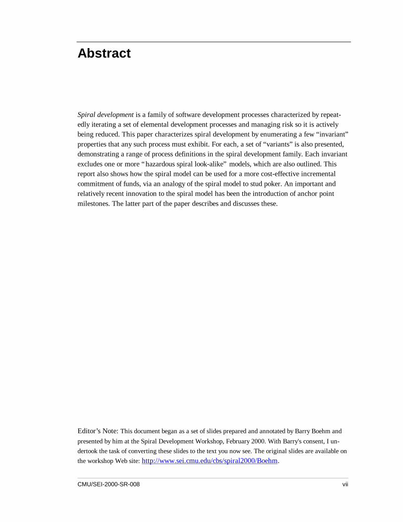
Spiral development is a family of software development processes characterized by repeat-edly iterating a set of elemental development processes and managing risk so it is activelybeing reduced. This paper characterizes spiral development by enumerating a few “invariant”properties that any such process must exhibit. For each, a set of “variants” is also presented,demonstrating a range of process definitions in the spiral development family. Each invariantexcludes one or more “hazardous spiral look-alike” models, which are also outlined. Thisreport also shows how the spiral model can be used for a more cost-effective incrementalcommitment of funds, via an analogy of the spiral model to stud poker. An important andrelatively recent innovation to the spiral model has been the introduction of anchor pointmilestones. The latter part of the paper describes and discusses these.
Editor’s Note: This document began as a set of slides prepared and annotated by Barry Boehm andpresented by him at the Spiral Development Workshop, February 2000. With Barry's consent, I un-dertook the task of converting these slides to the text you now see. The original slides are available onthe workshop Web site: http://www.sei.cmu.edu/cbs/spiral2000/Boehm.

viii CMU/SEI-2000-SR-008
CMU/SEI-2000-SR-008 1
1 Introduction
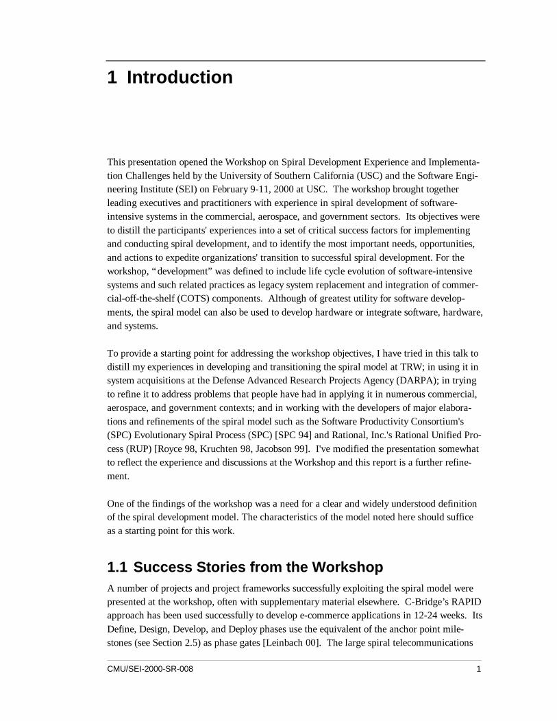
This presentation opened the Workshop on Spiral Development Experience and Implementa-tion Challenges held by the University of Southern California (USC) and the Software Engi-neering Institute (SEI) on February 9-11, 2000 at USC. The workshop brought togetherleading executives and practitioners with experience in spiral development of software-intensive systems in the commercial, aerospace, and government sectors. Its objectives wereto distill the participants' experiences into a set of critical success factors for implementingand conducting spiral development, and to identify the most important needs, opportunities,and actions to expedite organizations' transition to successful spiral development. For theworkshop, “development” was defined to include life cycle evolution of software-intensivesystems and such related practices as legacy system replacement and integration of commer-cial-off-the-shelf (COTS) components. Although of greatest utility for software develop-ments, the spiral model can also be used to develop hardware or integrate software, hardware,and systems.
To provide a starting point for addressing the workshop objectives, I have tried in this talk todistill my experiences in developing and transitioning the spiral model at TRW; in using it insystem acquisitions at the Defense Advanced Research Projects Agency (DARPA); in tryingto refine it to address problems that people have had in applying it in numerous commercial,aerospace, and government contexts; and in working with the developers of major elabora-tions and refinements of the spiral model such as the Software Productivity Consortium's(SPC) Evolutionary Spiral Process (SPC) [SPC 94] and Rational, Inc.'s Rational Unified Pro-cess (RUP) [Royce 98, Kruchten 98, Jacobson 99]. I've modified the presentation somewhatto reflect the experience and discussions at the Workshop and this report is a further refine-ment.
One of the findings of the workshop was a need for a clear and widely understood definitionof the spiral development model. The characteristics of the model noted here should sufficeas a starting point for this work.
1.1 Success Stories from the WorkshopA number of projects and project frameworks successfully exploiting the spiral model werepresented at the workshop, often with supplementary material elsewhere. C-Bridge’s RAPIDapproach has been used successfully to develop e-commerce applications in 12-24 weeks. ItsDefine, Design, Develop, and Deploy phases use the equivalent of the anchor point mile-stones (see Section 2.5) as phase gates [Leinbach 00]. The large spiral telecommunications
2 CMU/SEI-2000-SR-008
applications discussed in [Bernstein 00] and [DeMillo 00] use a complementary best practiceas their anchor point milestones: the AT&T/Lucent/Telcordia Architecture Review Board pro-cess [AT&T 93]. Xerox’s Time-to-Market process uses the anchor point milestones as hard-ware-software synchronization points for its printer business line [Hantos 00].
Several successful large aerospace spiral projects were also discussed. The best documentedof these is the CCPDS-R project discussed in [Royce 98]. Its Ada Process Model was thepredecessor of the Rational Unified Process and USC MBASE approach, which have bothbeen used on a number of successful spiral projects [Jacobson 99, Boehm 98], as has the SPCEvolutionary Spiral Process [SPC 94]. Further successful large aerospace spiral projectswere presented by SAIC and TRW [Kitaoka 00, Bostelaar 00].
RQTS PLANLIFE CYCLE PLAN
CONCEPT OFOPERATION
EMULATIONS MODELSBENCHMARKS
REVIEW
COMMITMENTPARTITION
RISK ANALYSIS
RISKANAL.
RISK ANALYSIS
RISK ANALYSIS
PROTO-TYPE1
PROTOTYPE3
OPERATIONALPROTOTYPE
EVALUATEALTERNATIVESIDENTIFY,RESOLVE RISKS
PROGRESSTHROUGHSTEPS
CUMMULATIVECOST
DETERMINEOBJECTIVES,ALTERNATIVES,CONSTRAINTS
DEVELOP-MENT PLAN
INTEGRATIONAND TEST
PLAN
DESIGN VALIDATIONAND VERIFICATION
REQUIREMENTSVALIDATION
SOFTWAREPRODUCTDESIGN
DEVELOP, VERIFYNEXT LEVEL PRODUCT
SOFTWARERQTS
IMPLEMEN-TATION
ACCEPT-ANCE TEST
INTEGRA-TION AND
TEST
UNITTEST
CODE
DETAILEDDESIGN
PROTOTYPE2
PLAN NEXTPHASES
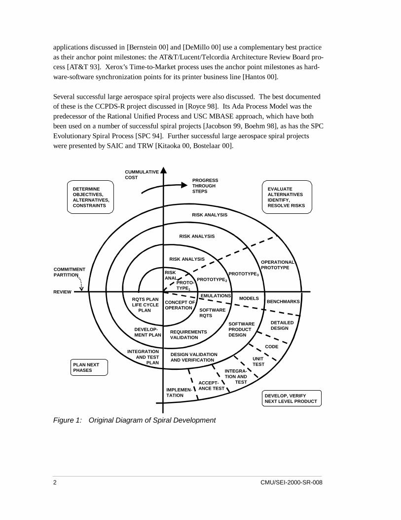
Figure 1: Original Diagram of Spiral Development
CMU/SEI-2000-SR-008 3
1.2 The Spiral Development Model
Figure 1 is a redrawing of the original spiral model diagram published by Boehm [Boehm88]. It captures the major spiral model features: cyclic concurrent engineering; risk drivendetermination of process and product; growing a system via risk-driven experimentation andelaboration; and lowering development cost by early elimination of nonviable alternativesand rework avoidance. As a result of planning and risk analysis, different projects maychoose different processes. That is, the spiral model is actually a risk-driven process modelgenerator, in which different risk patterns can lead to choosing incremental, waterfall, evolu-tionary prototyping, or other subsets of the process elements in the spiral model diagram.
For a number of reasons, however, the spiral model is not universally understood. For in-stance, Figure 1 contains some oversimplifications that have caused a number of misconcep-tions to propagate about the spiral model. These misconceptions may fit a few rare risk pat-terns, but are definitely not true for most risk patterns. The most significant misconceptionsto avoid are: that the spiral is just a sequence of waterfall increments; that everything on theproject follows a single spiral sequence; that every element in the diagram needs to be visitedin the order indicated; and that there can be no backtracking to revisit previous decisions. Inaddition to these misconceptions, other similar— but hazardously distinct— processes havebeen held up as spiral processes.
To promote understanding and effective use of the spiral model, this report more preciselycharacterizes the spiral model. We begin with a simple overview definition to capture theessence of the model:
The spiral development model is a risk-driven process model generator.It is used to guide multi-stakeholder concurrent engineering of software-intensive systems. It has two main distinguishing features. One is acyclic approach for incrementally growing a system's degree ofdefinition and implementation while decreasing its degree of risk. Theother is a set of anchor point milestones for ensuring stakeholdercommitment to feasible and mutually satisfactory system solutions.
Risks are situations or possible events that can cause a project to fail to meet its goals.They range in impact from trivial to fatal and in likelihood from certain to improb-able. A risk management plan enumerates the risks and prioritizes them in degree ofimportance, as measured by a combination of the impact and likelihood of each. Foreach risk the plan also states a mitigation strategy to deal with the risk. For instance,the risk that technology is unready may be mitigated by an appropriate prototype im-plementation in an early spiral cycle.
A process model answers two main questions:• What should be done next?
4 CMU/SEI-2000-SR-008
• For how long should it continue?Under the spiral model the answers to these questions are driven by risk considerations andvary from project to project and sometimes from one spiral cycle to the next. Each choice ofanswers generates a different process model. At the start of a cycle, all of the project’s suc-cess-critical stakeholders must participate concurrently in reviewing risks and choosing theproject’s process model accordingly. (Risk considerations also apply toward to ensuring thatprogress is not impeded by stakeholders’ overparticipation).
The cyclic nature of the spiral model was illustrated in Figure 1.
Anchor point milestones drive the spiral to progress toward completion and offer a means tocompare progress between one spiral project and another. The second half of the report ex-pands on these milestones. It also presents some experience-based refinements of the spiralmodel developed to address spiral usage problems encountered over the years: evolutionarydevelopment, Rational Unified Process (RUP), the WinWin spiral model, and the Model-Based (System) Architecting and Software Engineering (MBASE) approach.
The spiral development model is more precisely characterized in the next section with invari-ant properties and their variants. Invariant 5 invokes the relatively new concept of “anchorpoint milestones.” These are considered in more depth in the third section. The fourth sectionpresents tables summarizing the material.

CMU/SEI-2000-SR-008 5
2 The Invariants and Their Variants
Those successfully following the spiral model discipline will find that their cycles invariantlydisplay these six characteristics:
1. Concurrent rather than sequential determination of artifacts.2. Consideration in each spiral cycle of the main spiral elements:
− critical-stakeholder objectives and constraints− product and process alternatives− risk identification and resolution− stakeholder review− commitment to proceed
3. Using risk considerations to determine the level of effort to be devoted to each activitywithin each spiral cycle.
4. Using risk considerations to determine the degree of detail of each artifact produced ineach spiral cycle.
5. Managing stakeholder life-cycle commitments with three anchor point milestones:− Life Cycle Objectives (LCO)− Life Cycle Architecture (LCA)− Initial Operational Capability (IOC)
6. Emphasis on activities and artifacts for system and life cycle rather than for softwareand initial development.
Subsequent sections describe each of these invariants, the critical-success-factor reasons whyit is an essential invariant, and its associated optional variants. Examples are given, includingan analogy with stud poker which demonstrates how the spiral model accommodates cost-effective incremental commitment of funds. Many processes are adopted which may seem tobe instances of the spiral model, but lack essential invariants and thus risk failure. Each in-variant excludes one or more such process models, which we call “hazardous spiral look-alikes.” They are cataloged and pilloried as part of describing the invariants.
6 CMU/SEI-2000-SR-008
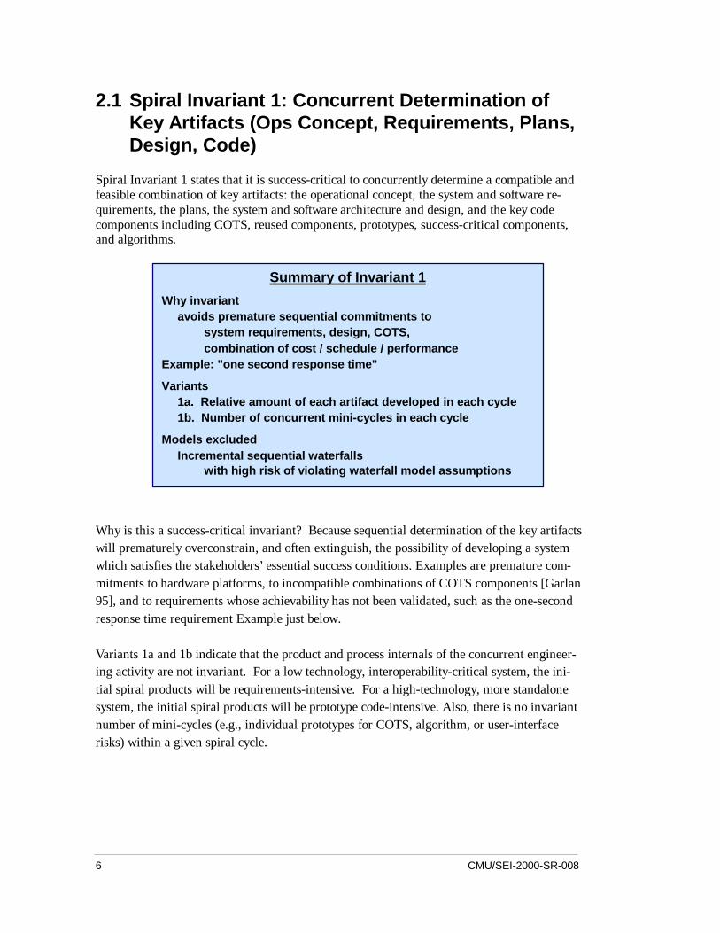
2.1 Spiral Invariant 1: Concurrent Determination ofKey Artifacts (Ops Concept, Requirements, Plans,Design, Code)
Spiral Invariant 1 states that it is success-critical to concurrently determine a compatible andfeasible combination of key artifacts: the operational concept, the system and software re-quirements, the plans, the system and software architecture and design, and the key codecomponents including COTS, reused components, prototypes, success-critical components,and algorithms.
Why is this a success-critical invariant? Because sequential determination of the key artifactswill prematurely overconstrain, and often extinguish, the possibility of developing a systemwhich satisfies the stakeholders’ essential success conditions. Examples are premature com-mitments to hardware platforms, to incompatible combinations of COTS components [Garlan95], and to requirements whose achievability has not been validated, such as the one-secondresponse time requirement Example just below.
Variants 1a and 1b indicate that the product and process internals of the concurrent engineer-ing activity are not invariant. For a low technology, interoperability-critical system, the ini-tial spiral products will be requirements-intensive. For a high-technology, more standalonesystem, the initial spiral products will be prototype code-intensive. Also, there is no invariantnumber of mini-cycles (e.g., individual prototypes for COTS, algorithm, or user-interfacerisks) within a given spiral cycle.
Summary of Invariant 1
Why invariantavoids premature sequential commitments to
system requirements, design, COTS,combination of cost / schedule / performance
Example: "one second response time"
Variants1a. Relative amount of each artifact developed in each cycle1b. Number of concurrent mini-cycles in each cycle
Models excludedIncremental sequential waterfalls
with high risk of violating waterfall model assumptions
CMU/SEI-2000-SR-008 7
Example: One-Second Response Time
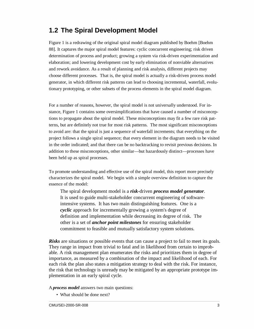
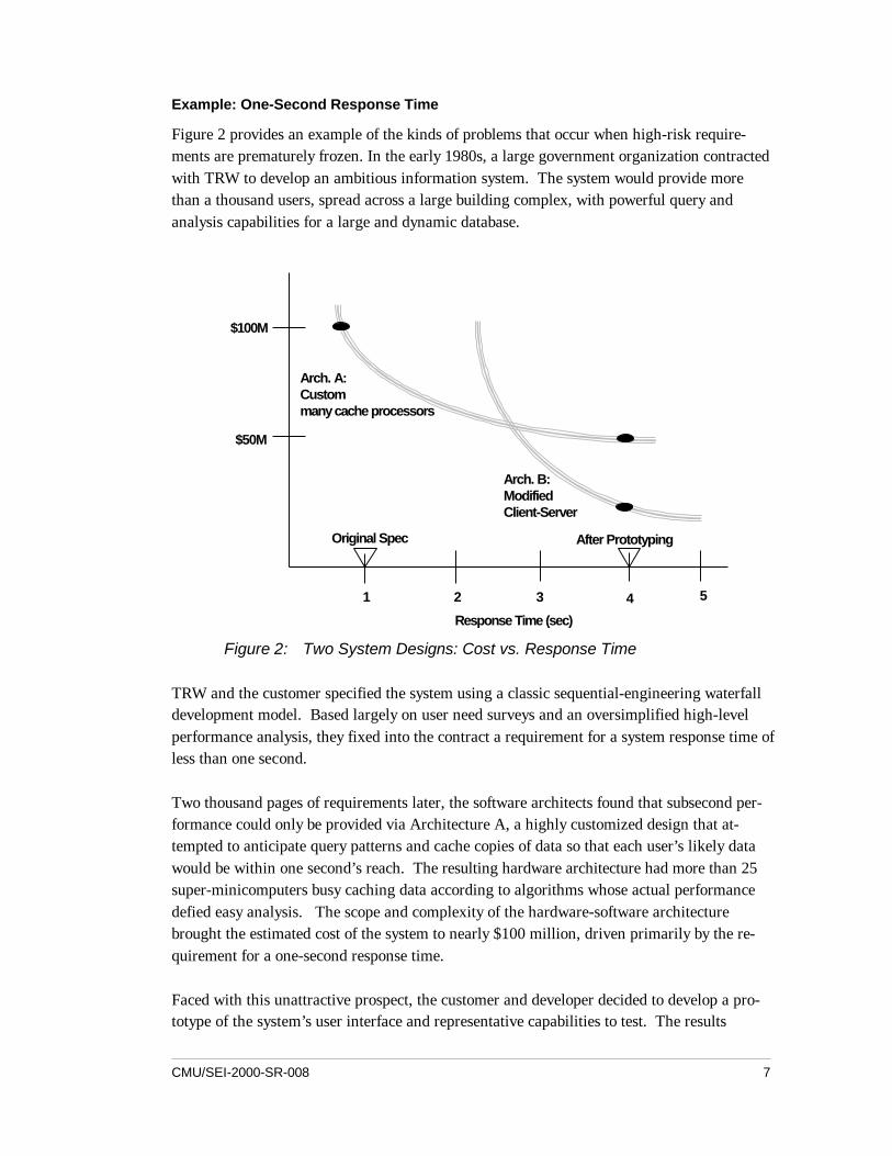
Figure 2 provides an example of the kinds of problems that occur when high-risk require-ments are prematurely frozen. In the early 1980s, a large government organization contractedwith TRW to develop an ambitious information system. The system would provide morethan a thousand users, spread across a large building complex, with powerful query andanalysis capabilities for a large and dynamic database.
$100M
$50M
Arch. A:Custommany cache processors
Arch. B:ModifiedClient-Server
1 2 3 4 5
Response Time (sec)
Original Spec After Prototyping
Figure 2: Two System Designs: Cost vs. Response Time
TRW and the customer specified the system using a classic sequential-engineering waterfalldevelopment model. Based largely on user need surveys and an oversimplified high-levelperformance analysis, they fixed into the contract a requirement for a system response time ofless than one second.
Two thousand pages of requirements later, the software architects found that subsecond per-formance could only be provided via Architecture A, a highly customized design that at-tempted to anticipate query patterns and cache copies of data so that each user’s likely datawould be within one second’s reach. The resulting hardware architecture had more than 25super-minicomputers busy caching data according to algorithms whose actual performancedefied easy analysis. The scope and complexity of the hardware-software architecturebrought the estimated cost of the system to nearly $100 million, driven primarily by the re-quirement for a one-second response time.
Faced with this unattractive prospect, the customer and developer decided to develop a pro-totype of the system’s user interface and representative capabilities to test. The results
8 CMU/SEI-2000-SR-008
showed that a four-second response time would satisfy users 90 percent of the time. A four-second response time could be achieved with Architecture B, cutting development costs to$30 million [Boehm 00a]. Thus, the premature specification of a one-second response timeinserted the hidden risk of creating an overly expensive and time-consuming system devel-opment.
Hazardous Spiral Look-Alike: Violation of Waterfall Assumptions
Invariant 1 excludes one model often labeled as a spiral process, but which is actually a “haz-ardous spiral look-alike.” This is the use of a sequence of incremental waterfall developmentswith a high risk of violating the underlying assumptions of the waterfall model. These as-sumptions are
1. The requirements are knowable in advance of implementation.2. The requirements have no unresolved, high-risk implications, such as risks due to
COTS choices, cost, schedule, performance, safety, security, user interfaces, andorganizational impacts.
3. The nature of the requirements will not change very much either during development orevolution.
4. The requirements are compatible with all the key system stakeholders’ expectations,including users, customer, developers, maintainers, investors.
5. The right architecture for implementing the requirements is well understood.6. There is enough calendar time to proceed sequentially.
These assumptions must be met by a project if the waterfall model is to succeed. If all ofthese are true, then it is a project risk not to specify the requirements, and the waterfall modelbecomes a risk-driven special case of the spiral model. If any of the assumptions are untrue,then specifying a complete set of requirements in advance of risk resolution will commit aproject to assumptions/requirements mismatches that will lead the project into trouble.
Assumption 1— the requirements are knowable in advance of implementation— is generallyuntrue for new user-interactive systems, because of the IKIWISI syndrome. When asked fortheir required screen layout for a new decision-support system, users will generally say, “Ican’t tell you, but I’ll know it when I see it (IKIWISI).” In such cases, a concurrentprototyping/requirements/architecture approach is essential.
The effects of invalidity in Assumptions 2, 4, and 5 are well illustrated by the example inFigure 2. The one-second response time requirement was unresolved and high-risk. It wascompatible with the users’ expectations, but not with the customer’s budget expectations.And the need for an expensive custom architecture was not understood in advance.
The effects of invalidity in Assumptions 3 and 6 are well illustrated by electronic commerceprojects. In these projects the volatility of technology and the marketplace is so high that re-quirements and traceability updates will swamp the project in overhead. Furthermore, theamount of initial calendar time it takes to work out a complete set of detailed requirements
CMU/SEI-2000-SR-008 9
that are likely to change several times downstream is not a good investment of the scarce timeto market available to develop an initial operational capability.
2.2 Spiral Invariant 2: Each Cycle Does Objectives,Constraints, Alternatives, Risks, Review,Commitment to Proceed
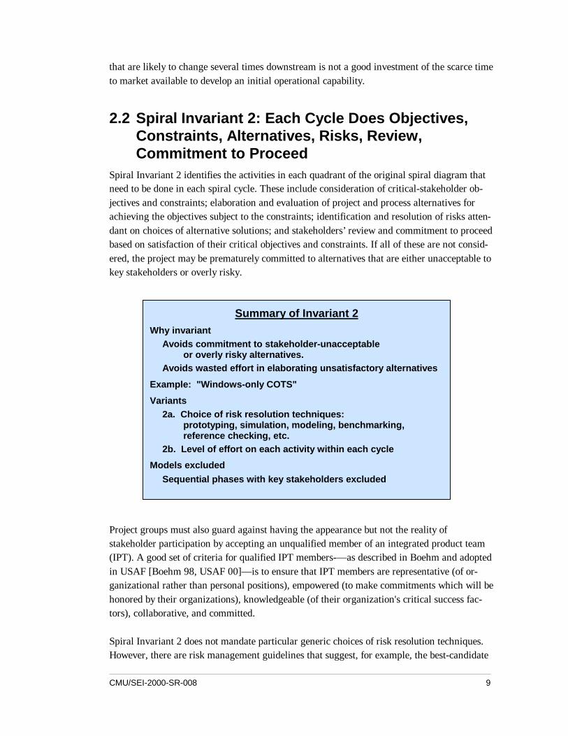
Spiral Invariant 2 identifies the activities in each quadrant of the original spiral diagram thatneed to be done in each spiral cycle. These include consideration of critical-stakeholder ob-jectives and constraints; elaboration and evaluation of project and process alternatives forachieving the objectives subject to the constraints; identification and resolution of risks atten-dant on choices of alternative solutions; and stakeholders’ review and commitment to proceedbased on satisfaction of their critical objectives and constraints. If all of these are not consid-ered, the project may be prematurely committed to alternatives that are either unacceptable tokey stakeholders or overly risky.
Project groups must also guard against having the appearance but not the reality ofstakeholder participation by accepting an unqualified member of an integrated product team(IPT). A good set of criteria for qualified IPT members-— as described in Boehm and adoptedin USAF [Boehm 98, USAF 00]— is to ensure that IPT members are representative (of or-ganizational rather than personal positions), empowered (to make commitments which will behonored by their organizations), knowledgeable (of their organization's critical success fac-tors), collaborative, and committed.
Spiral Invariant 2 does not mandate particular generic choices of risk resolution techniques.However, there are risk management guidelines that suggest, for example, the best-candidate
Summary of Invariant 2Why invariant
Avoids commitment to stakeholder-unacceptableor overly risky alternatives.
Avoids wasted effort in elaborating unsatisfactory alternatives
Example: "Windows-only COTS"
Variants2a. Choice of risk resolution techniques:
prototyping, simulation, modeling, benchmarking,reference checking, etc.
2b. Level of effort on each activity within each cycle
Models excludedSequential phases with key stakeholders excluded
10 CMU/SEI-2000-SR-008
risk resolution techniques for the major sources of project risk [Boehm 89a]. This invariantalso does not mandate particular levels of effort for the activities performed during each cy-cle. Levels must be balanced between the risks of learning too little and the risks of wastingtime and effort gathering marginally useful information.
Example: Windows-Only COTS
Ignoring Invariant 2, can lead to a good deal of wasted effort in elaborating an alternative thatcould have been shown earlier to be unsatisfactory. One of the current USC digital libraryprojects is developing a web-based viewer for oversized artifacts (e.g., newspapers, large im-ages). The initial prototype featured a tremendously powerful and high-speed viewing capa-bility, based on a COTS product called ER Mapper. The initial project review approved se-lection of this COTS product, even though it only ran well on Windows platforms, and theLibrary had significant Macintosh and UNIX user communities. This decision was based oninitial indications that Mac and UNIX versions of ER Mapper would be available soon.
However, subsequent investigations indicated that it would be a long time before such Macand UNIX capabilities would become available. At a subsequent review, ER Mapper wasdropped in favor of a less powerful but fully portable COTS product, Mr. SID, but only aftera good deal of effort was wasted on elaborating the ER Mapper solution. If a representativeof the Mac or UNIX user community had been involved in the early project decisions, thehomework leading to choosing Mr. SID would have been done earlier, and the wasted effortin elaborating the ER Mapper solution would have been avoided.
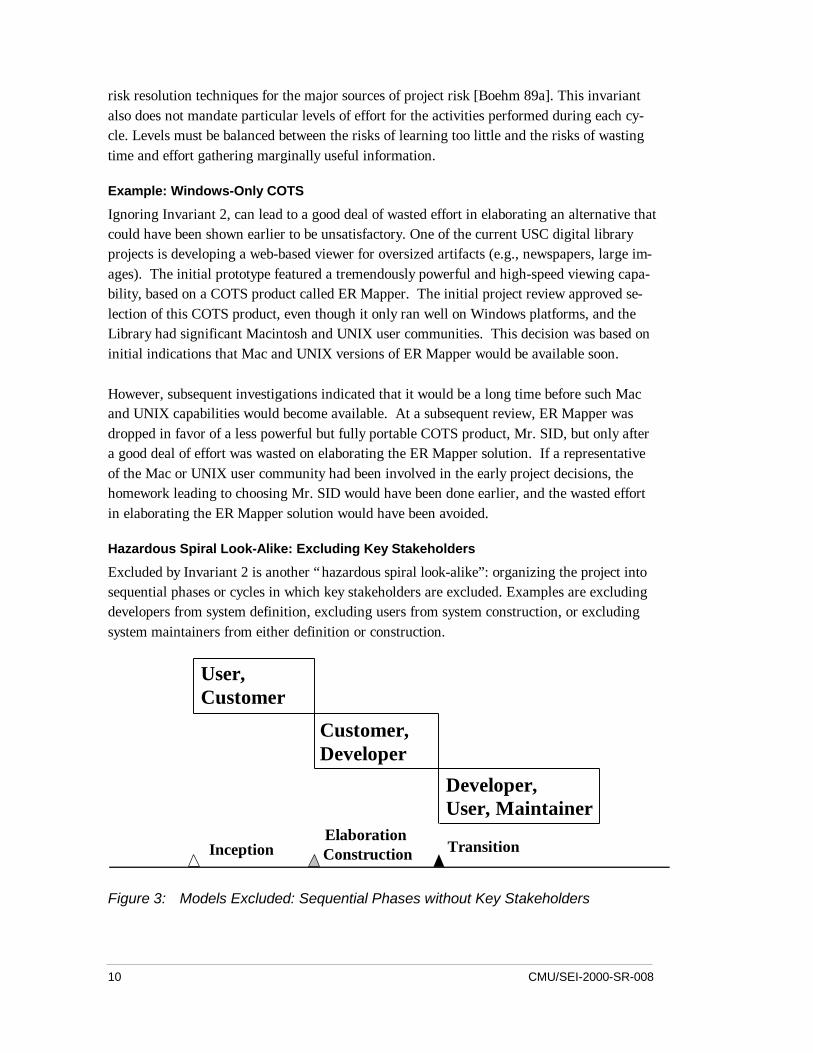
Hazardous Spiral Look-Alike: Excluding Key Stakeholders
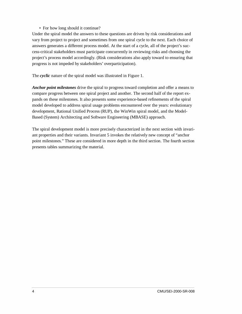
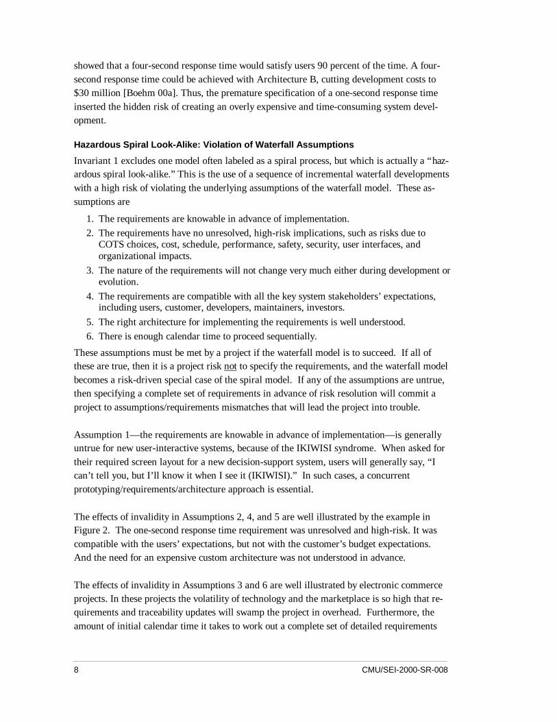
Excluded by Invariant 2 is another “hazardous spiral look-alike”: organizing the project intosequential phases or cycles in which key stakeholders are excluded. Examples are excludingdevelopers from system definition, excluding users from system construction, or excludingsystem maintainers from either definition or construction.
User,Customer
Customer,Developer
Developer,User, Maintainer
InceptionElaboration,Construction Transition
Figure 3: Models Excluded: Sequential Phases without Key Stakeholders
CMU/SEI-2000-SR-008 11
Even though the phases shown in Figure 3 may look like risk-driven spiral cycles, this spirallook-alike will be hazardous because its exclusion of key stakeholders is likely to cause criti-cal risks to go undetected. Excluding developer participation in early cycles can lead to proj-ect commitments based on unrealistic assumptions about developer capabilities. Excludingusers or maintainers from development cycles can lead to win-lose situations, which gener-ally evolve into lose-lose situations [Boehm 89b].
2.3 Spiral Invariant 3: Level of Effort Driven by RiskConsiderations
Spiral Invariant 3 dictates the use of risk considerations to answer the difficult questions ofhow-much-is-enough of a given activity. How much is enough of domain engineering?prototyping? testing? configuration management? and so on.
If you plot a project's risk exposure as a function of time spent prototyping, there is a point atwhich risk exposure is minimized. Spending significantly more time than this is an overkillleading to late market entry and decreased market penetration. Spending significantly lesstime prototyping is an underkill, leading to premature development with significant delaysdue to unanticipated snags. Given that risk profiles vary from project to project, this meansthat the risk-minimizing level of prototyping effort will vary from project to project. Theamount of effort devoted to other activities will also vary as a function of a project's risk pro-file.
Variants to be considered include the choice of methods used to pursue activities (e.g.,MBASE/WinWin, Rational RUP, JAD, QFD, ESP) and the degree of detail of artifacts pro-duced in each cycle. Another variant is an organization's choice of particular methods for riskassessment and management.
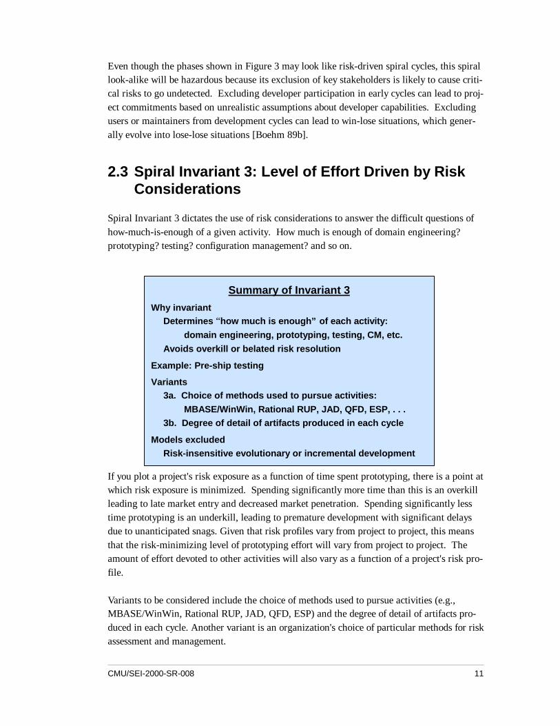
Summary of Invariant 3Why invariant
Determines “how much is enough” of each activity:domain engineering, prototyping, testing, CM, etc.
Avoids overkill or belated risk resolution
Example: Pre-ship testing
Variants3a. Choice of methods used to pursue activities:
MBASE/WinWin, Rational RUP, JAD, QFD, ESP, . . .3b. Degree of detail of artifacts produced in each cycle
Models excludedRisk-insensitive evolutionary or incremental development
12 CMU/SEI-2000-SR-008
Example: Pre-Ship Testing
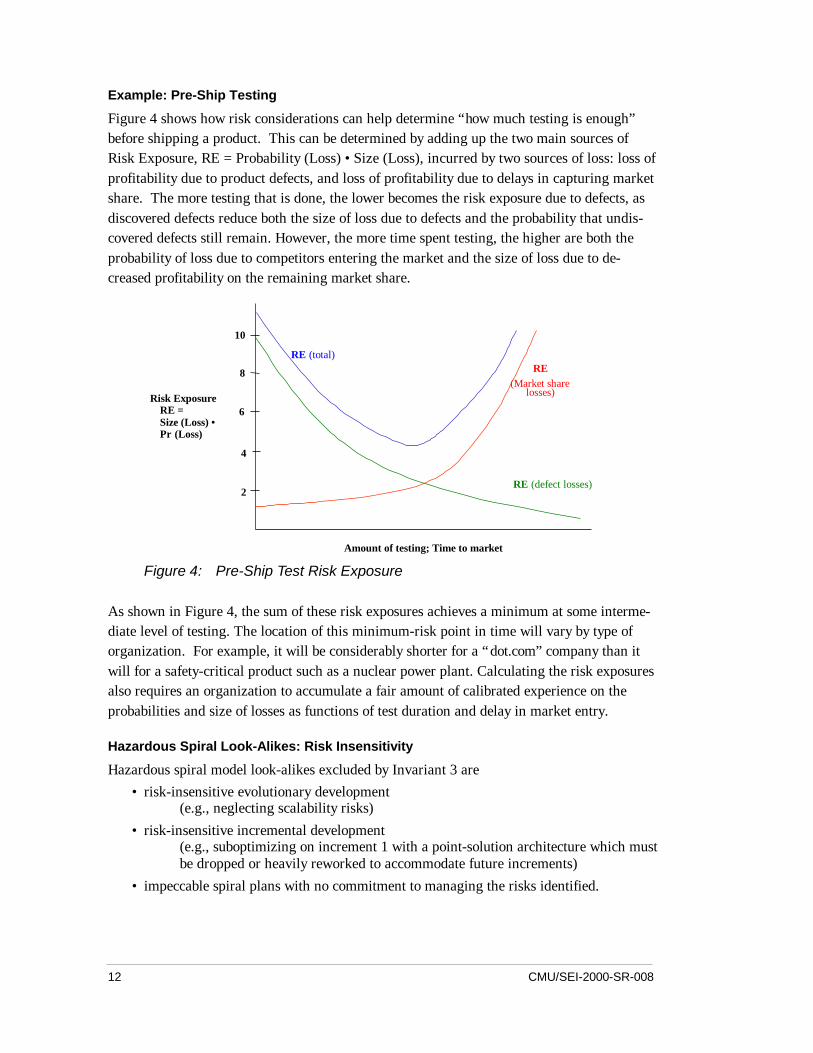
Figure 4 shows how risk considerations can help determine “how much testing is enough”before shipping a product. This can be determined by adding up the two main sources ofRisk Exposure, RE = Probability (Loss) • Size (Loss), incurred by two sources of loss: loss ofprofitability due to product defects, and loss of profitability due to delays in capturing marketshare. The more testing that is done, the lower becomes the risk exposure due to defects, asdiscovered defects reduce both the size of loss due to defects and the probability that undis-covered defects still remain. However, the more time spent testing, the higher are both theprobability of loss due to competitors entering the market and the size of loss due to de-creased profitability on the remaining market share.
Risk ExposureRE =Size (Loss) •Pr (Loss)
Amount of testing; Time to market
10
8
6
4
2
RE(Market share
losses)
RE (total)
RE (defect losses)
Figure 4: Pre-Ship Test Risk Exposure
As shown in Figure 4, the sum of these risk exposures achieves a minimum at some interme-diate level of testing. The location of this minimum-risk point in time will vary by type oforganization. For example, it will be considerably shorter for a “dot.com” company than itwill for a safety-critical product such as a nuclear power plant. Calculating the risk exposuresalso requires an organization to accumulate a fair amount of calibrated experience on theprobabilities and size of losses as functions of test duration and delay in market entry.
Hazardous Spiral Look-Alikes: Risk Insensitivity
Hazardous spiral model look-alikes excluded by Invariant 3 are• risk-insensitive evolutionary development
(e.g., neglecting scalability risks)• risk-insensitive incremental development
(e.g., suboptimizing on increment 1 with a point-solution architecture which mustbe dropped or heavily reworked to accommodate future increments)
• impeccable spiral plans with no commitment to managing the risks identified.
CMU/SEI-2000-SR-008 13
2.4 Spiral Invariant 4: Degree of Detail Driven by RiskConsiderations
Spiral Invariant 4 is the product counterpart of Invariant 3: that risk considerations determinethe degree of detail of products as well as processes. This means, for example, that the tradi-tional ideal of a complete, consistent, traceable, testable requirements specification is not agood idea for certain product components, such as a graphic user interface (GUI) or COTSinterface. Here, the risk of precisely specifying screen layouts in advance of developmentinvolves a high probability of locking an awkward user interface into the development con-tract, while the risk of not specifying screen layouts is low, given the general availability offlexible GUI-builder tools. Even aiming for full consistency and testability can be risky, as itcreates a pressure to prematurely specify decisions that would better be deferred (e.g., theform and content of exception reports). However, some risk patterns make it very importantto have precise specifications, such as the risks of safety-critical interface mismatches be-tween hardware and software components, or between a prime contractor’s and a subcon-tractor’s software.
This guideline shows when it is risky to over-specify and under-specify software features:• If it's risky to not specify precisely, DO specify
(e.g., hardware-software interface, prime-subcontractor interface)• If it's risky to specify precisely, DO NOT specify
(e.g., GUI layout, COTS behavior)
Spiral variants related to Invariant 4 are the choices of representations for product artifacts.
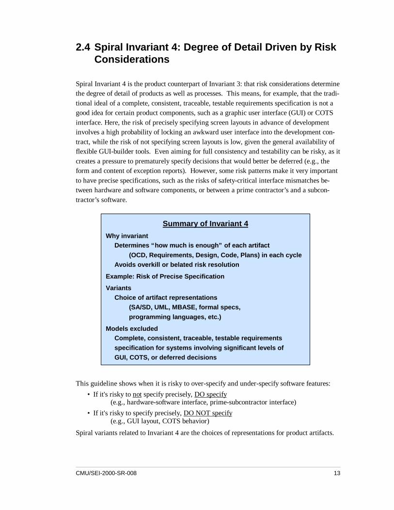
Summary of Invariant 4Why invariant
Determines “how much is enough” of each artifact(OCD, Requirements, Design, Code, Plans) in each cycle
Avoids overkill or belated risk resolution
Example: Risk of Precise Specification
VariantsChoice of artifact representations
(SA/SD, UML, MBASE, formal specs,programming languages, etc.)
Models excludedComplete, consistent, traceable, testable requirementsspecification for systems involving significant levels ofGUI, COTS, or deferred decisions
14 CMU/SEI-2000-SR-008
Example: Risk of Precise Specification
One editor specification required that every operation be available through a button on thewindow. As a result, the space available for viewing and editing became unusably small. Thedeveloper was precluded from moving some operations to menus because the GUI layout hadbeen specified precisely at an early step. (Of course, given too much freedom programmerscan develop very bad GUIs. Stakeholder review is essential to avoid such problems.)
2.5 Spiral Invariant 5: Use of Anchor Point Milestones:LCO, LCA, IOC
A major difficulty of the original spiral model was its lack of intermediate milestones to serveas commitment points and progress checkpoints [Forsberg 96]. This difficulty has been reme-died by the development of a set of anchor point milestones: Life Cycle Objectives (LCO),Life Cycle Architecture (LCA), and Initial Operational Capability (IOC) [Boehm 96]. Thesecan be described as stakeholder commitment points in the software life cycle: LCO is thestakeholders’ commitment to support architecting; LCA is the stakeholders' commitment tosupport full life cycle; and IOC is the stakeholders' commitment to support operations.
The anchor point milestones were defined in a pair of USC Center for Software EngineeringAffiliates’ workshops, and as such represent joint efforts by both industry and governmentparticipants [Clark 95]. One of the Affiliates, Rational, Inc., had been defining the phases ofits Rational Unified Process (RUP), and adopted the anchor point milestones as its phasegates.
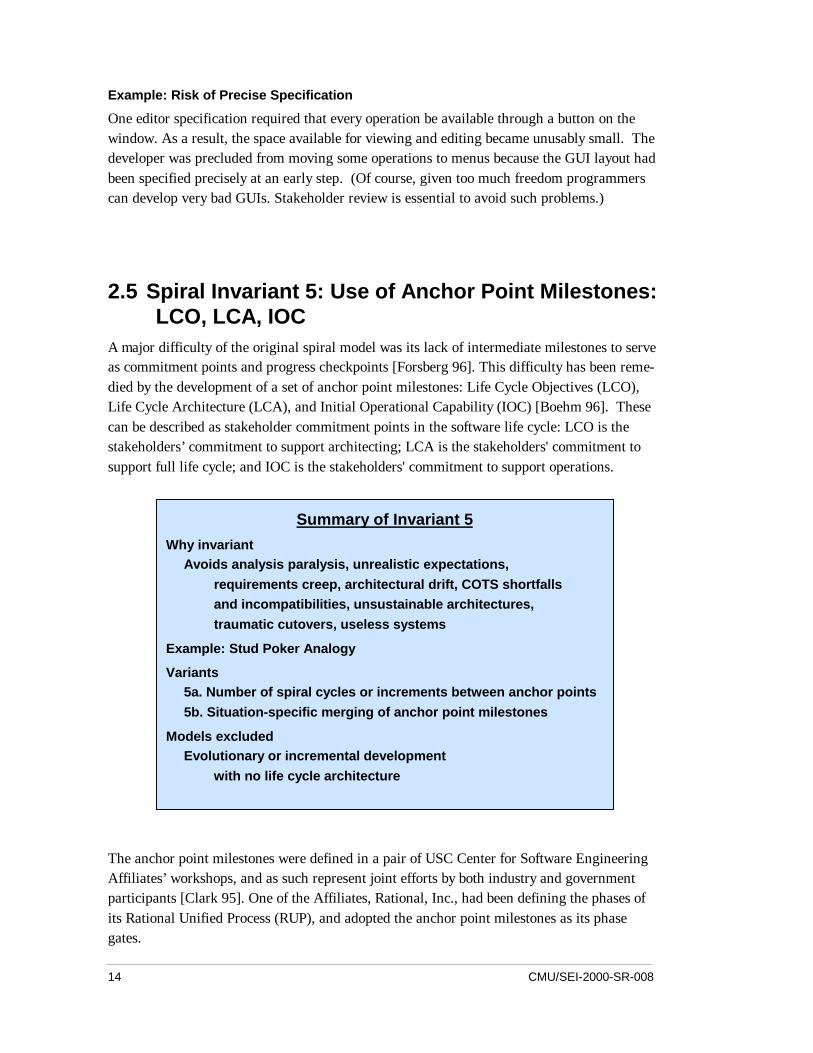
Summary of Invariant 5Why invariant
Avoids analysis paralysis, unrealistic expectations,requirements creep, architectural drift, COTS shortfallsand incompatibilities, unsustainable architectures,traumatic cutovers, useless systems
Example: Stud Poker Analogy
Variants5a. Number of spiral cycles or increments between anchor points5b. Situation-specific merging of anchor point milestones
Models excludedEvolutionary or incremental development
with no life cycle architecture
CMU/SEI-2000-SR-008 15
The first two anchor points are the Life Cycle Objectives (LCO) and Life Cycle Architecture(LCA). At each of these anchor points the key stakeholders review six artifacts: operationalconcept description, prototyping results, requirements description, architecture description,life cycle plan, and feasibility rationale (see Section 3.1 for details).
The feasibility rationale covers the key pass/fail question: “If I build this product using thespecified architecture and processes, will it support the operational concept, realize theprototyping results, satisfy the requirements, and finish within the budgets and schedules inthe plan?” If not, the package should be reworked.
The focus of the LCO review is to ensure that at least one architecture choice is viable from abusiness perspective. The focus of the LCA review is to commit to a single detailed defini-tion of the review artifacts. The project must have either eliminated all significant risks orput in place an acceptable risk-management plan. The LCA milestone is particularly impor-tant, as its pass/fail criteria enable stakeholders to hold up projects attempting to proceed intoevolutionary or incremental development without a life cycle architecture.
The LCO milestone is the equivalent of getting engaged, and the LCA milestone is theequivalent of getting married. As in life, if you marry your architecture in haste, you andyour stakeholders will repent at leisure. The third anchor point milestone, the Initial Opera-tional Capability (IOC), constitutes an even larger commitment: It is the equivalent of havingyour first child.
Appropriate variants include the number of spiral cycles of development increments betweenthe anchor points. In some cases, anchor point milestones can be merged. In particular, aproject deciding to use a mature and appropriately scalable fourth generation language (4GL)or product line framework will have already determined its choice of life cycle architectureby its LCO milestone, enabling the LCO and LCA milestones to be merged.
Further elucidation and discussion of the anchor point milestones is deferred to Section 3.
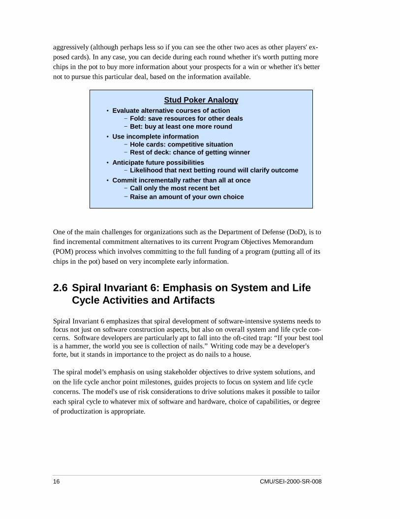
Spiral Model and Incremental Commitment: Stud Poker Analogy
A valuable aspect of the original application of the spiral model to the TRW Software Pro-ductivity System was its ability to support incremental commitment of corporate resources tothe exploration, definition, and development of the system, rather than requiring a large out-lay of resources to the project before its success prospects were well understood [Boehm 88].These decisions are codified with the specific guidelines of the LCO and LCA.
Funding a spiral development can thus be likened to the game of stud poker. You can put acouple of chips in the pot and receive two cards, one hidden and one exposed, along with theother players in the game. If your cards don't promise a winning outcome, you can drop outwithout a great loss. If your two cards are both aces, you will probably bet on your prospects
16 CMU/SEI-2000-SR-008
aggressively (although perhaps less so if you can see the other two aces as other players' ex-posed cards). In any case, you can decide during each round whether it's worth putting morechips in the pot to buy more information about your prospects for a win or whether it's betternot to pursue this particular deal, based on the information available.
One of the main challenges for organizations such as the Department of Defense (DoD), is tofind incremental commitment alternatives to its current Program Objectives Memorandum(POM) process which involves committing to the full funding of a program (putting all of itschips in the pot) based on very incomplete early information.
2.6 Spiral Invariant 6: Emphasis on System and LifeCycle Activities and Artifacts
Spiral Invariant 6 emphasizes that spiral development of software-intensive systems needs tofocus not just on software construction aspects, but also on overall system and life cycle con-cerns. Software developers are particularly apt to fall into the oft-cited trap: “If your best toolis a hammer, the world you see is collection of nails.” Writing code may be a developer'sforte, but it stands in importance to the project as do nails to a house.
The spiral model’s emphasis on using stakeholder objectives to drive system solutions, andon the life cycle anchor point milestones, guides projects to focus on system and life cycleconcerns. The model's use of risk considerations to drive solutions makes it possible to tailoreach spiral cycle to whatever mix of software and hardware, choice of capabilities, or degreeof productization is appropriate.
Stud Poker Analogy• Evaluate alternative courses of action
− Fold: save resources for other deals− Bet: buy at least one more round
• Use incomplete information− Hole cards: competitive situation− Rest of deck: chance of getting winner
• Anticipate future possibilities− Likelihood that next betting round will clarify outcome
• Commit incrementally rather than all at once− Call only the most recent bet− Raise an amount of your own choice
CMU/SEI-2000-SR-008 17
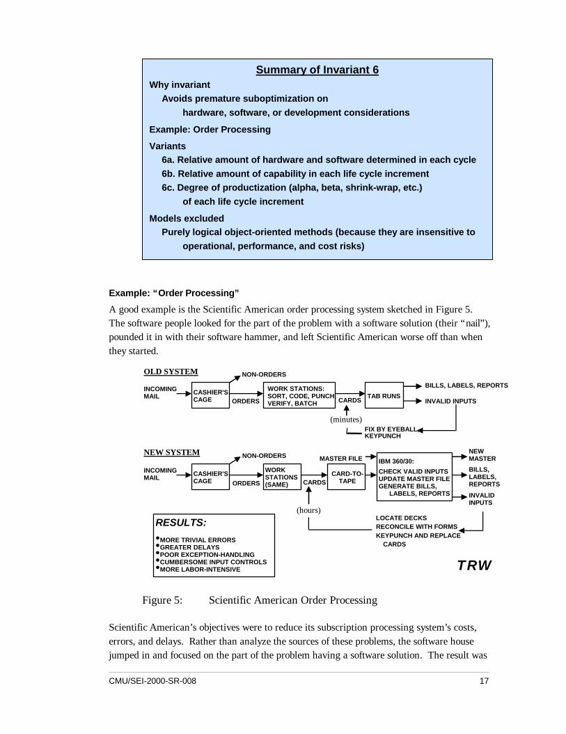
Example: “Order Processing”
A good example is the Scientific American order processing system sketched in Figure 5.The software people looked for the part of the problem with a software solution (their “nail”),pounded it in with their software hammer, and left Scientific American worse off than whenthey started.
RESULTS:•MORE TRIVIAL ERRORS•GREATER DELAYS•POOR EXCEPTION-HANDLING•CUMBERSOME INPUT CONTROLS•MORE LABOR-INTENSIVE
CASHIER'SCAGE TAB RUNS
WORK STATIONS:SORT, CODE, PUNCH,VERIFY, BATCH
OLD SYSTEM
INCOMINGMAIL
ORDERS
NON-ORDERS
CARDS
(minutes)
BILLS, LABELS, REPORTS
INVALID INPUTS
FIX BY EYEBALL,KEYPUNCH
WORKSTATIONS(SAME)
CARD-TO-TAPE
IBM 360/30:
CHECK VALID INPUTSUPDATE MASTER FILEGENERATE BILLS, LABELS, REPORTS
NEWMASTER
(hours)LOCATE DECKSRECONCILE WITH FORMSKEYPUNCH AND REPLACE CARDS
CARDSORDERS
NON-ORDERS
INCOMINGMAIL
NEW SYSTEM
BILLS,LABELS,REPORTS
INVALIDINPUTS
MASTER FILE
CASHIER'SCAGE
TRW
Figure 5: Scientific American Order Processing
Scientific American’s objectives were to reduce its subscription processing system’s costs,errors, and delays. Rather than analyze the sources of these problems, the software housejumped in and focused on the part of the problem having a software solution. The result was
Summary of Invariant 6Why invariant
Avoids premature suboptimization onhardware, software, or development considerations
Example: Order Processing
Variants6a. Relative amount of hardware and software determined in each cycle6b. Relative amount of capability in each life cycle increment6c. Degree of productization (alpha, beta, shrink-wrap, etc.)
of each life cycle increment
Models excludedPurely logical object-oriented methods (because they are insensitive to
operational, performance, and cost risks)
18 CMU/SEI-2000-SR-008
a batch-processing computer system whose long delays put extra strain on the clerical portionof the system that had been the major source of costs, errors, and delays in the first place. Asseen in the chart, the business outcome was a new system with more errors, greater delays,higher costs, and less attractive work than its predecessor [Boehm 81].
This kind of outcome would have resulted even if the software automating the tabulator-machine functions had been developed in a risk-driven cyclic approach. However, its LifeCycle Objectives milestone package would have failed its feasibility review, as it had nosystem-level business case demonstrating that the development of the software would lead tothe desired reduction in costs, errors, and delays. Had a thorough business case analysis beendone, it would have identified the need to re-engineer the clerical business processes as wellas to automate the manual tab runs. Further, as shown by recent methods such as the DMRBenefits Realization Approach, the business case could have been used to monitor the actualrealization of the expected benefits, and to apply corrective action to either the business proc-ess re-engineering or the software engineering portions of the solution (or both) as appropri-ate [Thorp 98].
Hazardous Spiral Look-Alikes: Logic-Only OO Designs
Models excluded by Invariant 6 include most published object-oriented analysis and design(OOA&D) methods, which are usually presented as abstract logical exercises independent ofsystem performance or economic concerns. For example, in a recent survey of 16 OOA&Dbooks, only six listed the word “performance” in their index, and only two listed “cost.”
CMU/SEI-2000-SR-008 19
3 Anchor Point Milestones
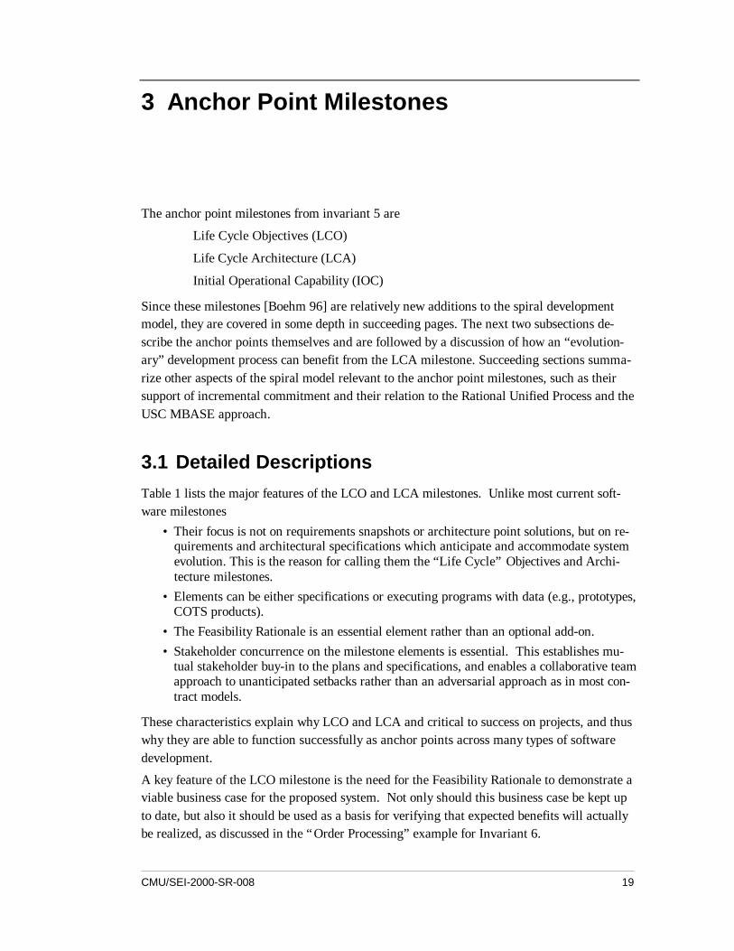
The anchor point milestones from invariant 5 are
Life Cycle Objectives (LCO)
Life Cycle Architecture (LCA)
Initial Operational Capability (IOC)
Since these milestones [Boehm 96] are relatively new additions to the spiral developmentmodel, they are covered in some depth in succeeding pages. The next two subsections de-scribe the anchor points themselves and are followed by a discussion of how an “evolution-ary” development process can benefit from the LCA milestone. Succeeding sections summa-rize other aspects of the spiral model relevant to the anchor point milestones, such as theirsupport of incremental commitment and their relation to the Rational Unified Process and theUSC MBASE approach.
3.1 Detailed DescriptionsTable 1 lists the major features of the LCO and LCA milestones. Unlike most current soft-ware milestones
• Their focus is not on requirements snapshots or architecture point solutions, but on re-quirements and architectural specifications which anticipate and accommodate systemevolution. This is the reason for calling them the “Life Cycle” Objectives and Archi-tecture milestones.
• Elements can be either specifications or executing programs with data (e.g., prototypes,COTS products).
• The Feasibility Rationale is an essential element rather than an optional add-on.• Stakeholder concurrence on the milestone elements is essential. This establishes mu-
tual stakeholder buy-in to the plans and specifications, and enables a collaborative teamapproach to unanticipated setbacks rather than an adversarial approach as in most con-tract models.
These characteristics explain why LCO and LCA and critical to success on projects, and thuswhy they are able to function successfully as anchor points across many types of softwaredevelopment.
A key feature of the LCO milestone is the need for the Feasibility Rationale to demonstrate aviable business case for the proposed system. Not only should this business case be kept upto date, but also it should be used as a basis for verifying that expected benefits will actuallybe realized, as discussed in the “Order Processing” example for Invariant 6.
20 CMU/SEI-2000-SR-008
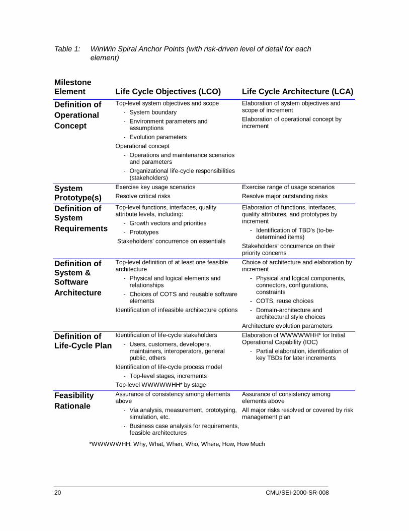
Table 1: WinWin Spiral Anchor Points (with risk-driven level of detail for eachelement)
MilestoneElement Life Cycle Objectives (LCO) Life Cycle Architecture (LCA)
Definition ofOperationalConcept
Top-level system objectives and scope- System boundary- Environment parameters and
assumptions- Evolution parameters
Operational concept- Operations and maintenance scenarios
and parameters- Organizational life-cycle responsibilities
(stakeholders)
Elaboration of system objectives andscope of incrementElaboration of operational concept byincrement
SystemPrototype(s)
Exercise key usage scenariosResolve critical risks
Exercise range of usage scenariosResolve major outstanding risks
Definition ofSystemRequirements
Top-level functions, interfaces, qualityattribute levels, including:
- Growth vectors and priorities- Prototypes
Stakeholders’ concurrence on essentials
Elaboration of functions, interfaces,quality attributes, and prototypes byincrement
- Identification of TBD’s (to-be-determined items)
Stakeholders’ concurrence on theirpriority concerns
Definition ofSystem &SoftwareArchitecture
Top-level definition of at least one feasiblearchitecture
- Physical and logical elements andrelationships
- Choices of COTS and reusable softwareelements
Identification of infeasible architecture options
Choice of architecture and elaboration byincrement
- Physical and logical components,connectors, configurations,constraints
- COTS, reuse choices- Domain-architecture and
architectural style choicesArchitecture evolution parameters
Definition ofLife-Cycle Plan
Identification of life-cycle stakeholders- Users, customers, developers,
maintainers, interoperators, generalpublic, others
Identification of life-cycle process model- Top-level stages, increments
Top-level WWWWWHH* by stage
Elaboration of WWWWWHH* for InitialOperational Capability (IOC)
- Partial elaboration, identification ofkey TBDs for later increments
FeasibilityRationale
Assurance of consistency among elementsabove
- Via analysis, measurement, prototyping,simulation, etc.
- Business case analysis for requirements,feasible architectures
Assurance of consistency amongelements aboveAll major risks resolved or covered by riskmanagement plan
*WWWWWHH: Why, What, When, Who, Where, How, How Much
CMU/SEI-2000-SR-008 21
A feature distinguishing the LCA milestone from the LCO milestone is the need to have all ofthe system's major risks resolved, or at least covered by an element of the system's risk man-agement plan. For large systems, passing the LCA milestone is the point of significant esca-lation of staff level and resource commitments. Proceeding into this stage with major risksunaddressed has led to disaster for many large projects. Some good guidelines for softwarerisk assessment can be found in [Boehm 89a, Charette 89, Carr 93, Hall 98].
The Initial Operational capability (IOC) is the first the users will see of a functioning system,so getting things wrong in the IOC can have serious consequences. Greeting users with anew system having ill-matched software, poor site preparation, or poor users preparation hasbeen a frequent source of user alienation and project failure.
The key elements of the IOC milestone are
• Software preparation, including both operational and support software with appropriatecommentary and documentation; data preparation or conversion; the necessary licensesand rights for COTS and reused software, and appropriate operational readiness testing.
• Site preparation, including facilities, equipment, supplies, and COTS vendor supportarrangements.
• User, operator and maintainer preparation, including selection, teambuilding, trainingand other qualification for familiarization, usage, operations, or maintenance.
As with the Pre-Ship Testing Example given with Invariant 3, the IOC milestone is risk-driven with respect to the system objectives determined in the LCO and LCA milestones.Thus, for example, these objectives drive the tradeoff between IOC date and quality of theproduct. These will differ markedly between such systems as the safety-critical Space ShuttleSoftware and a market-window-critical commercial software product. The difference be-tween these two cases is narrowing as commercial vendors and users increasingly appreciatethe market risks involved in buggy products [Cusumano 95].
3.2 Relationships to Other Process ModelsThis section sketches four process models that have adopted portions of the spiral model orextended the spiral model.
Evolutionary DevelopmentAll too often, a project will be started on an evolutionary development approach based on astatement such as, “We're not sure what to build, so let's throw together a prototype andevolve it until the users are satisfied.” This approach is insensitive to several risks corre-sponding to the set of assumptions for a successful evolutionary. These assumptions are:
1. The initial release is sufficiently satisfactory to key system stakeholders that they willcontinue to participate in its evolution.
22 CMU/SEI-2000-SR-008
2. The architecture of the initial release is scalable to accommodate the full set of systemlife cycle requirements (e.g., performance, safety, security, distribution, localization).
3. The operational user organizations are sufficiently flexible to adapt to the pace ofsystem evolution
4. The dimensions of system evolution are compatible with the dimensions of evolving-out the legacy systems it is replacing.
Without some initial attention to user needs, as required for LCO and LCA, the prototypemay be so far from the users' needs that they consider it a waste of time to continue. As dis-cussed above, it will be risky to proceed without a life cycle architecture to support evolution.Another risk is “information sclerosis”: the propensity for organizations to lock into opera-tional procedures making it difficult to evolve toward better capabilities [Boehm 88]. A finalfrequent risk is that legacy systems are often too inflexible to adapt to desired directions ofevolution. In such cases, a preferable process model is incremental development, with theincrements determined by the ease of evolving-out portions of the legacy system.
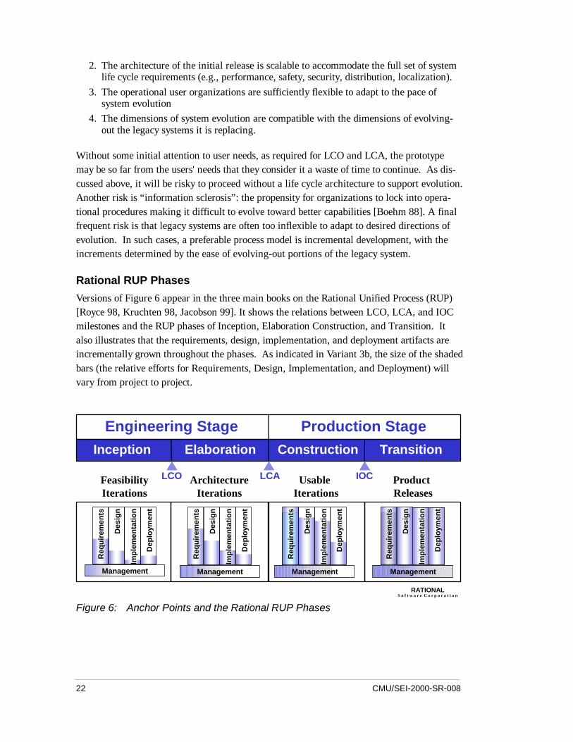
Rational RUP PhasesVersions of Figure 6 appear in the three main books on the Rational Unified Process (RUP)[Royce 98, Kruchten 98, Jacobson 99]. It shows the relations between LCO, LCA, and IOCmilestones and the RUP phases of Inception, Elaboration Construction, and Transition. Italso illustrates that the requirements, design, implementation, and deployment artifacts areincrementally grown throughout the phases. As indicated in Variant 3b, the size of the shadedbars (the relative efforts for Requirements, Design, Implementation, and Deployment) willvary from project to project.
Inception Elaboration Construction Transition
Engineering Stage Production Stage
Req
uire
men
ts
Des
ign
Impl
emen
tatio
n
Dep
loym
ent
Management
Req
uire
men
ts
Des
ign
Impl
emen
tatio
n
Dep
loym
ent
Management
Req
uire
men
ts
Des
ign
Impl
emen
tatio
n
Dep
loym
ent
Management
Req
uire
men
ts
Des
ign
Impl
emen
tatio
n
Dep
loym
ent
Management
FeasibilityIterations
ArchitectureIterations
Usable Iterations
Product Releases
LCO LCA IOC
RATIONALS o f t w a r e C o r p o r a t i o n
Figure 6: Anchor Points and the Rational RUP Phases
CMU/SEI-2000-SR-008 23
WinWin Spiral Model
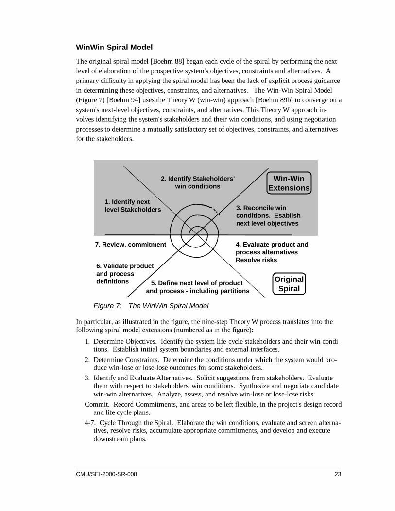
The original spiral model [Boehm 88] began each cycle of the spiral by performing the nextlevel of elaboration of the prospective system's objectives, constraints and alternatives. Aprimary difficulty in applying the spiral model has been the lack of explicit process guidancein determining these objectives, constraints, and alternatives. The Win-Win Spiral Model(Figure 7) [Boehm 94] uses the Theory W (win-win) approach [Boehm 89b] to converge on asystem's next-level objectives, constraints, and alternatives. This Theory W approach in-volves identifying the system's stakeholders and their win conditions, and using negotiationprocesses to determine a mutually satisfactory set of objectives, constraints, and alternativesfor the stakeholders.
4. Evaluate product andprocess alternativesResolve risks
5. Define next level of product and process - including partitions
6. Validate productand process definitions
7. Review, commitment
Win-WinExtensions
OriginalSpiral
1. Identify next level Stakeholders
2. Identify Stakeholders'win conditions
3. Reconcile winconditions. Esablishnext level objectives
Figure 7: The WinWin Spiral Model
In particular, as illustrated in the figure, the nine-step Theory W process translates into thefollowing spiral model extensions (numbered as in the figure):
1. Determine Objectives. Identify the system life-cycle stakeholders and their win condi-tions. Establish initial system boundaries and external interfaces.
2. Determine Constraints. Determine the conditions under which the system would pro-duce win-lose or lose-lose outcomes for some stakeholders.
3. Identify and Evaluate Alternatives. Solicit suggestions from stakeholders. Evaluatethem with respect to stakeholders' win conditions. Synthesize and negotiate candidatewin-win alternatives. Analyze, assess, and resolve win-lose or lose-lose risks.
Commit. Record Commitments, and areas to be left flexible, in the project's design recordand life cycle plans.
4-7. Cycle Through the Spiral. Elaborate the win conditions, evaluate and screen alterna-tives, resolve risks, accumulate appropriate commitments, and develop and executedownstream plans.
24 CMU/SEI-2000-SR-008
MBASE Electronic Process Guide
The Model-Based (System) Architecting and Software Engineering (MBASE) approach[Boehm 99a, Boehm 99b, Boehm 00b], provides more detailed definitions of the anchor pointmilestone elements [Boehm 00b], and a process guide for deriving them. LCO and LCA areboth described as consisting of Operational Concept Definition, Requirements Definition,Architecture Definition, Life Cycle Plan, Key Prototypes, and Feasibility Rationale. Each ofthese artifacts is described in detail.
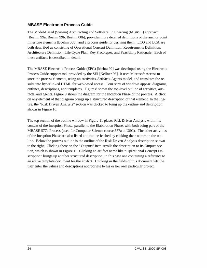
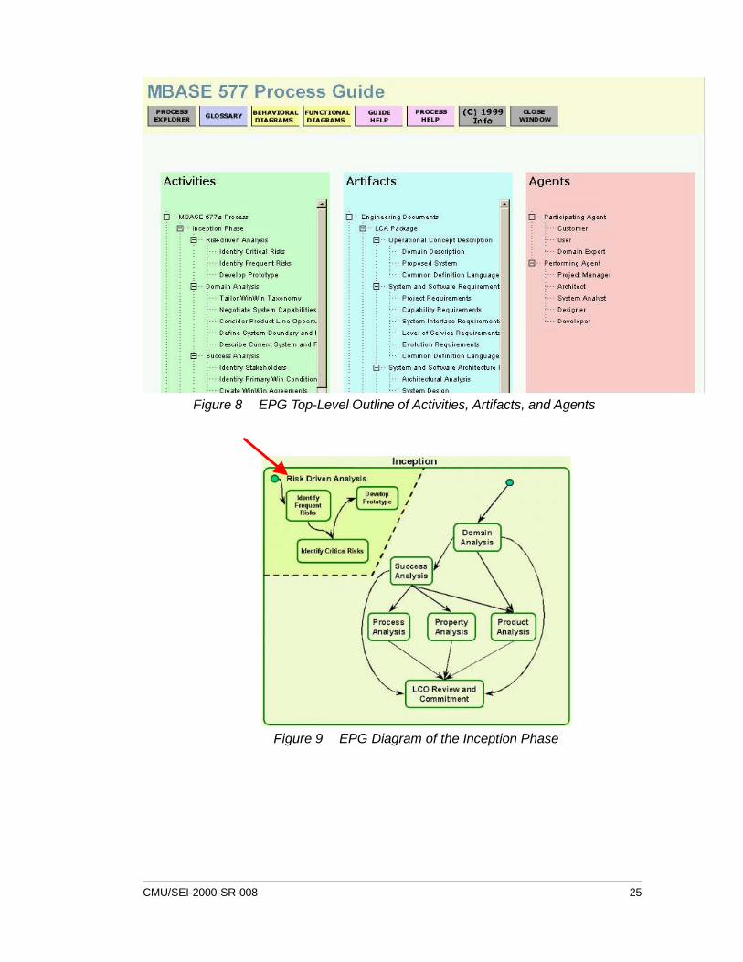
The MBASE Electronic Process Guide (EPG) [Mehta 99] was developed using the ElectronicProcess Guide support tool provided by the SEI [Kellner 98]. It uses Microsoft Access tostore the process elements, using an Activities-Artifacts-Agents model, and translates the re-sults into hyperlinked HTML for web-based access. Four sorts of windows appear: diagrams,outlines, descriptions, and templates. Figure 8 shows the top-level outline of activities, arti-facts, and agents. Figure 9 shows the diagram for the Inception Phase of the process. A clickon any element of that diagram brings up a structured description of that element. In the Fig-ure, the “Risk Driven Analysis” section was clicked to bring up the outline and descriptionshown in Figure 10.
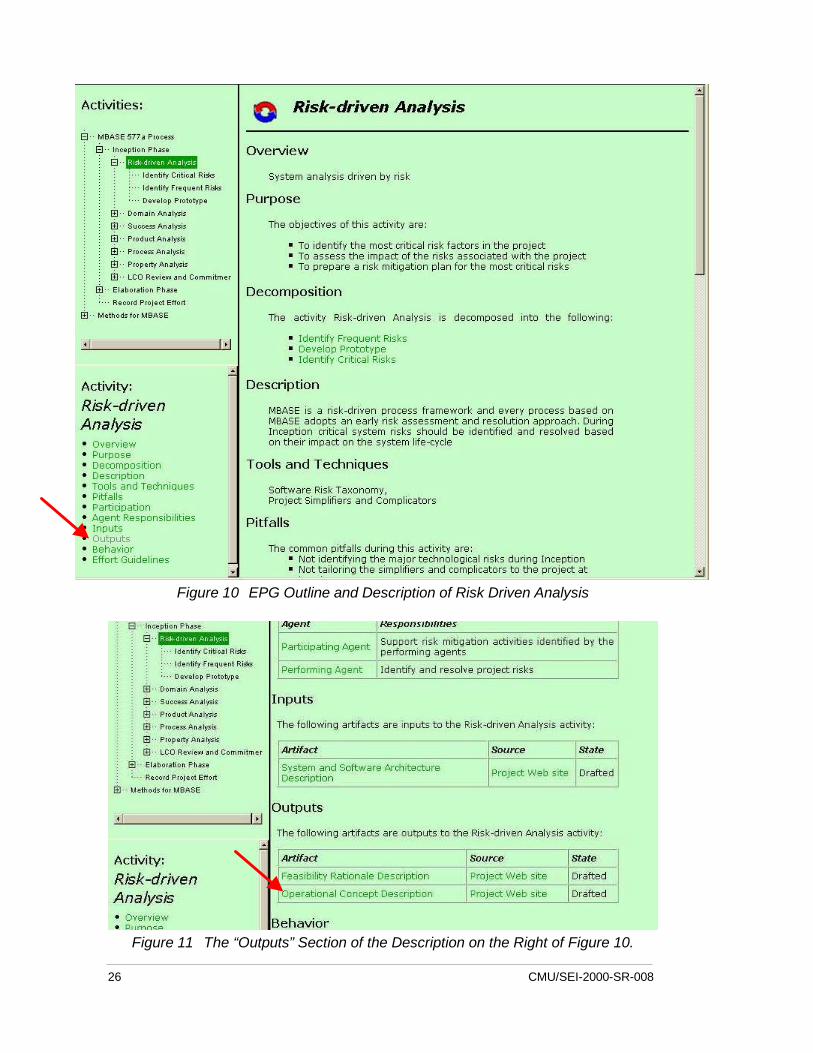
The top section of the outline window in Figure 11 places Risk Driven Analysis within itscontext of the Inception Phase, parallel to the Elaboration Phase, with both being part of theMBASE 577a Process (used for Computer Science course 577a at USC). The other activitiesof the Inception Phase are also listed and can be fetched by clicking their names in the out-line. Below the process outline is the outline of the Risk Driven Analysis description shownto the right. Clicking there on the “Outputs” item scrolls the description to its Outputs sec-tion, which is shown in Figure 10. Clicking an artifact name like “Operational Concept De-scription” brings up another structured description; in this case one containing a reference toan active template document for the artifact. Clicking in the fields of this document lets theuser enter the values and descriptions appropriate to his or her own particular project.
CMU/SEI-2000-SR-008 25
Figure 8 EPG Top-Level Outline of Activities, Artifacts, and Agents
Figure 9 EPG Diagram of the Inception Phase
26 CMU/SEI-2000-SR-008
Figure 10 EPG Outline and Description of Risk Driven Analysis
Figure 11 The “Outputs” Section of the Description on the Right of Figure 10.
CMU/SEI-2000-SR-008 27
4 Summary
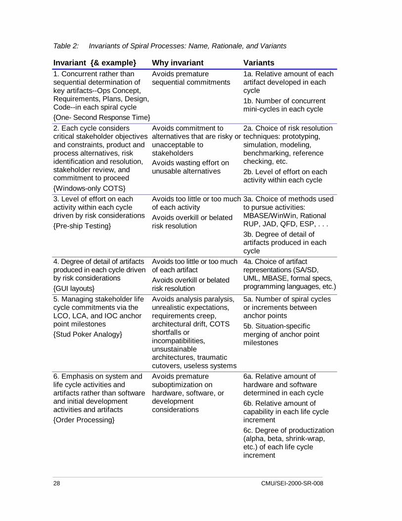
This paper has presented a preliminary definition of the spiral development model and char-acterized the model further by presenting a set of six “invariant” attributes. That is, six prop-erties which every spiral development process must incorporate. These are listed in Table 2along with a notion of why they are necessary and a few characteristics, called “variants,”that may vary from one spiral process model to another.
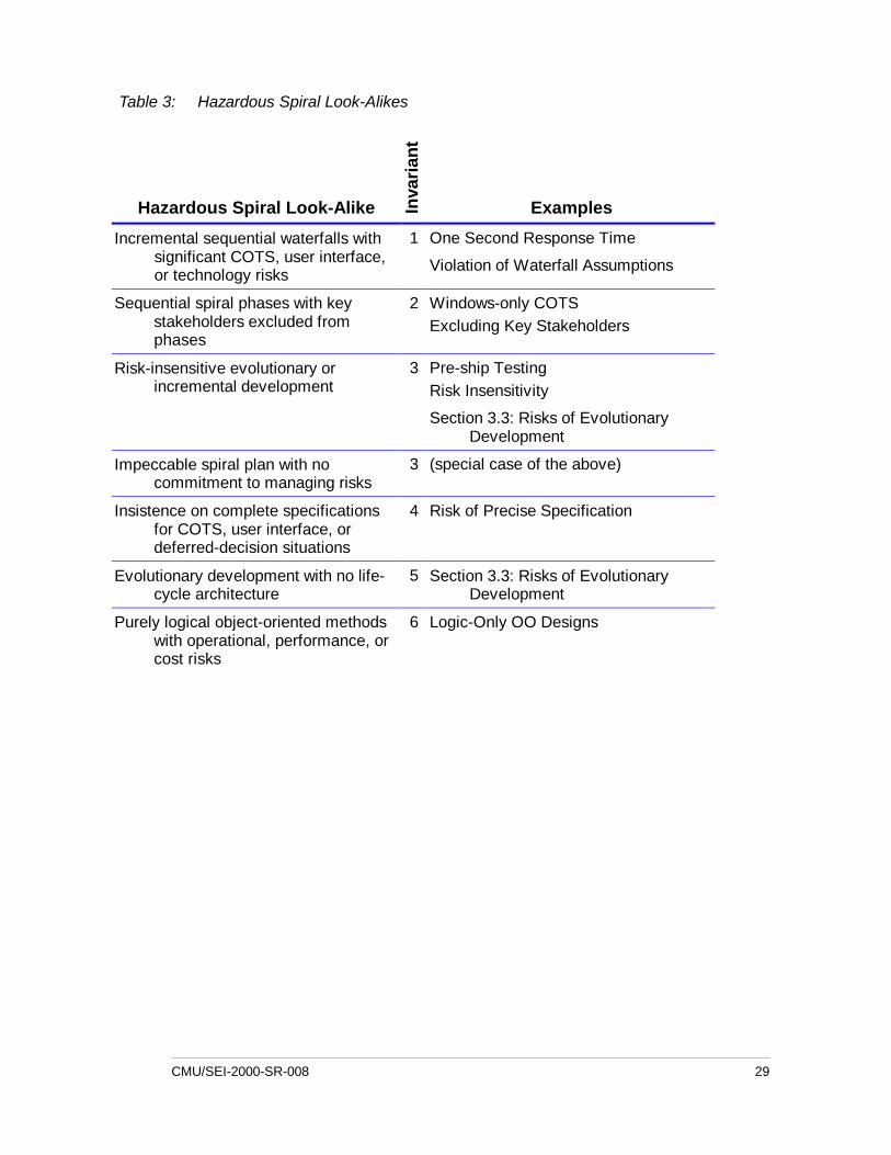
Numerous process models with development structured in a cyclic series of efforts can ap-pear to be spiral models and yet violate one or more invariants and subsequently fail. Theseare listed in Table 3, together with a reference to further discussion in the text.
The second part of the paper was devoted to the anchor point milestones of Invariant 5. Thesemilestones— Life Cycle Objectives (LCO), Life Cycle Architecture (LCA), and Initial Oper-ating Capability (IOC)— provide concrete artifacts to drive the project toward completion.They also provide for comparison, evaluation, and planning between projects. The discussionconcluded with the WinWin spiral model and MBASE, which assist in the use of the anchorpoint milestones.
This paper is intended as a sufficient characterization of the spiral development model to dis-tinguish it from other project process models. Although not within itself a full description anduser's guide for the spiral development model, it is a suitable basis for such further works.
28 CMU/SEI-2000-SR-008
Table 2: Invariants of Spiral Processes: Name, Rationale, and Variants
Invariant {& example} Why invariant Variants1. Concurrent rather thansequential determination ofkey artifacts--Ops Concept,Requirements, Plans, Design,Code--in each spiral cycle{One- Second Response Time}
Avoids prematuresequential commitments
1a. Relative amount of eachartifact developed in eachcycle1b. Number of concurrentmini-cycles in each cycle
2. Each cycle considerscritical stakeholder objectivesand constraints, product andprocess alternatives, riskidentification and resolution,stakeholder review, andcommitment to proceed{Windows-only COTS}
Avoids commitment toalternatives that are risky orunacceptable tostakeholdersAvoids wasting effort onunusable alternatives
2a. Choice of risk resolutiontechniques: prototyping,simulation, modeling,benchmarking, referencechecking, etc.2b. Level of effort on eachactivity within each cycle
3. Level of effort on eachactivity within each cycledriven by risk considerations{Pre-ship Testing}
Avoids too little or too muchof each activityAvoids overkill or belatedrisk resolution
3a. Choice of methods usedto pursue activities:MBASE/WinWin, RationalRUP, JAD, QFD, ESP, . . .3b. Degree of detail ofartifacts produced in eachcycle
4. Degree of detail of artifactsproduced in each cycle drivenby risk considerations{GUI layouts}
Avoids too little or too muchof each artifactAvoids overkill or belatedrisk resolution
4a. Choice of artifactrepresentations (SA/SD,UML, MBASE, formal specs,programming languages, etc.)
5. Managing stakeholder lifecycle commitments via theLCO, LCA, and IOC anchorpoint milestones{Stud Poker Analogy}
Avoids analysis paralysis,unrealistic expectations,requirements creep,architectural drift, COTSshortfalls orincompatibilities,unsustainablearchitectures, traumaticcutovers, useless systems
5a. Number of spiral cyclesor increments betweenanchor points5b. Situation-specificmerging of anchor pointmilestones
6. Emphasis on system andlife cycle activities andartifacts rather than softwareand initial developmentactivities and artifacts{Order Processing}
Avoids prematuresuboptimization onhardware, software, ordevelopmentconsiderations
6a. Relative amount ofhardware and softwaredetermined in each cycle6b. Relative amount ofcapability in each life cycleincrement6c. Degree of productization(alpha, beta, shrink-wrap,etc.) of each life cycleincrement
CMU/SEI-2000-SR-008 29
Table 3: Hazardous Spiral Look-Alikes
Hazardous Spiral Look-Alike Inva
rian
t
Examples
Incremental sequential waterfalls withsignificant COTS, user interface,or technology risks
1 One Second Response Time
Violation of Waterfall Assumptions
Sequential spiral phases with keystakeholders excluded fromphases
2 Windows-only COTSExcluding Key Stakeholders
Risk-insensitive evolutionary orincremental development
3 Pre-ship TestingRisk Insensitivity
Section 3.3: Risks of EvolutionaryDevelopment
Impeccable spiral plan with nocommitment to managing risks
3 (special case of the above)
Insistence on complete specificationsfor COTS, user interface, ordeferred-decision situations
4 Risk of Precise Specification
Evolutionary development with no life-cycle architecture
5 Section 3.3: Risks of EvolutionaryDevelopment
Purely logical object-oriented methodswith operational, performance, orcost risks
6 Logic-Only OO Designs

30 CMU/SEI-2000-SR-008
CMU/SEI-2000-SR-008 31
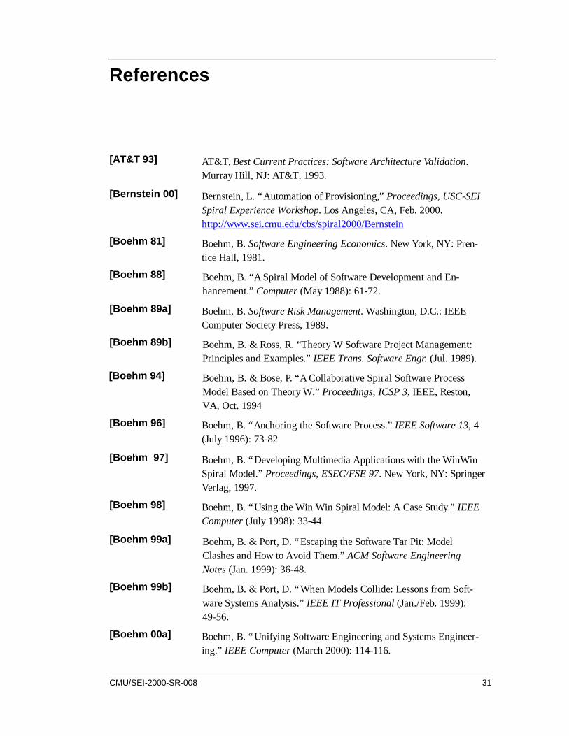
References
[AT&T 93] AT&T, Best Current Practices: Software Architecture Validation.Murray Hill, NJ: AT&T, 1993.
[Bernstein 00] Bernstein, L. “Automation of Provisioning,” Proceedings, USC-SEISpiral Experience Workshop. Los Angeles, CA, Feb. 2000.http://www.sei.cmu.edu/cbs/spiral2000/Bernstein
[Boehm 81] Boehm, B. Software Engineering Economics. New York, NY: Pren-tice Hall, 1981.
[Boehm 88] Boehm, B. “A Spiral Model of Software Development and En-hancement.” Computer (May 1988): 61-72.
[Boehm 89a] Boehm, B. Software Risk Management. Washington, D.C.: IEEEComputer Society Press, 1989.
[Boehm 89b] Boehm, B. & Ross, R. “Theory W Software Project Management:Principles and Examples.” IEEE Trans. Software Engr. (Jul. 1989).
[Boehm 94] Boehm, B. & Bose, P. “A Collaborative Spiral Software ProcessModel Based on Theory W.” Proceedings, ICSP 3, IEEE, Reston,VA, Oct. 1994
[Boehm 96] Boehm, B. “Anchoring the Software Process.” IEEE Software 13, 4(July 1996): 73-82
[Boehm 97] Boehm, B. “Developing Multimedia Applications with the WinWinSpiral Model.” Proceedings, ESEC/FSE 97. New York, NY: SpringerVerlag, 1997.
[Boehm 98] Boehm, B. “Using the Win Win Spiral Model: A Case Study.” IEEEComputer (July 1998): 33-44.
[Boehm 99a] Boehm, B. & Port, D. “Escaping the Software Tar Pit: ModelClashes and How to Avoid Them.” ACM Software EngineeringNotes (Jan. 1999): 36-48.
[Boehm 99b] Boehm, B. & Port, D. “When Models Collide: Lessons from Soft-ware Systems Analysis.” IEEE IT Professional (Jan./Feb. 1999):49-56.
[Boehm 00a] Boehm, B. “Unifying Software Engineering and Systems Engineer-ing.” IEEE Computer (March 2000): 114-116.
32 CMU/SEI-2000-SR-008
[Boehm 00b] Boehm, B; Abi-Antoun, M; Brown, A.W.; Mehta, N. & Port, D.“Guidelines for the LCO and LCA Deliverables for MBASE.” USC-CSE, Mar. 2000. http://sunset.usc.edu/classes/cs577b_2000/EP/07/MBASE_Guidelines_for_CS577v0_2.pdf
[Bostelaar 00] Bostelaar, T. “TRW Spiral Development Experience on Command &Control Product Lines Program,” Proceedings, USC-SEI Spiral Ex-perience Workshop. Los Angeles, CA., Feb. 2000.http://www.sei.cmu.edu/cbs/spiral2000/Bostelaar
[Carr 93] Carr, M.; Kondra, S.; Monarch, I.; Ulrich, F. & Walker, C. Taxon-omy-Based Risk Identification (CMU/SEI-93-TR-06 ADA 266992)Pittsburgh, PA: Software Engineering Institute, Carnegie MellonUniversity, 1993 http://www.sei.cmu.edu/publications/documents/93.reports/93.tr.006.html.
[Charette 89] Charette, R.N. Software Engineering Risk Analysis and Manage-ment. New York, NY: McGraw Hill, 1989.
[Clark 95] Clark, B. & Boehm, B. (eds.) “Knowledge Summary: FocusedWorkshop on COCOMO 2.0,” USC-CSE, May 16-18, 1995.
[Cusumano 95] Cusumano, M.& Selby, R. Microsoft Secrets. New York, NY: FreePress, 1995
[DeMillo 00] DeMillo, R. “Continual Improvement: Spiral Software Develop-ment,” Proceedings, USC-SEI Spiral Experience Workshop. LosAngeles, CA, Feb. 2000.http://www.sei.cmu.edu/cbs/spiral2000/DeMillo
[Forsberg 96] Forsberg, K; Mooz, H. & Cotterman, H. Visualizing Project Man-agement. New York, NY: Wiley Publishers, 1996.
[Garlan 95] Garlan, D.; Allen, R. & Ockerbloom, J. “Architectural Mismatch:Why Reuse Is So Hard,” IEEE Software (Nov 1995): 17-26.
[Hall 98] Hall, E. Managing Risk: Methods for Software Systems Develop-ment. Reading, MA: Addison Wesley, 1998.
[Hantos 00] Hantos, P. “From Spiral to Anchored Processes: A Wild Ride inLifecycle Architecting,” Proceedings, USC-SEI Spiral ExperienceWorkshop. Los Angeles, CA, Feb. 2000.http://www.sei.cmu.edu/cbs/spiral2000/Hantos
[Jacobson 99] Jacobson, I; Booch, G. & Rumbaugh, J. The Unified Software De-velopment Process. Reading, MA: Addison-Wesley, 1999.
CMU/SEI-2000-SR-008 33
[Kellner 98] “Process Guides: Effective Guidance for Process Participants,”Proceedings of the 5th International Conference on the SoftwareProcess: Computer Supported Organizational Work. Los Alamitos,CA: IEEE Comput. Soc. Press, 1998.
[Kitaoka 00] Kitaoka, B. “Yesterday, Today & Tomorrow: Implementations ofthe Development Lifecycles,” Proceedings, USC-SEI Spiral Expe-rience Workshop. Los Angeles, CA, Feb 2000.http://www.sei.cmu.edu/cbs/spiral2000/Kitaoka
[Kruchten 98] Krutchten, P. The Rational Unified Process. Reading, MA:Addison-Wesley, 1998.
[Leinbach 00] Leinbach, C. “E-Business and Spiral Development,” Proceedings,USC-SEI Spiral Experience Workshop. Los Angeles, CA, Feb 2000.http://www.sei.cmu.edu/cbs/spiral2000/Leinbach
[Mehta 99] Mehta, N. MBASE Electronic Process Guide. USC-CSE, Los An-geles, CA: Oct 1999. http://sunset.usc.edu/research/MBASE/EPG
[Royce 98] Royce, W. Software Project Management: A Unified Framework.Reading, MA: Addison Wesley, 1998.
[SPC 94] Software Productivity Consortium, Process Engineering with theEvolutionary Spiral Process Model (SPC-93098-CMC, Version01.00.06). Herndon, Virginia, 1994.
[Thorp 98] Thorp, J. The Information Paradox. New York, NY: McGraw Hill,1998.
[USAF 00] U.S. Air Force. “Evolutionary Acquisition for C2 Systems.” AirForce Instruction (January 1, 2000) 63-123.

34 CMU/SEI-2000-SR-008
CMU/SEI-2000-SR-008 35
Acronyms
AC2ISRC Aerospace Command and Control, Intelligence, Surveillance, andReconnaissance Command (Air Force)
AFOTEC Air Force Operational Test and Evaluation Center
ASC Aeronautical Systems Center
C2ISR Command and Control, Intelligence, Surveillance, and Reconnaissance
CCPDS-R Command center processing and display system replacement
CECOM US Army Communications-Electronics Command
CIO Chief Information Officer
CMU Carnegie Mellon University, home of SEI
COTS Commercial-Off-The-Shelf
CSE Center for Software Engineering, USC
DAU Defense Acquisition University
DCMC Defense Contract Management Command
DoD Department of Defense
DSMC Defense Systems Management College
ESC Electronic Systems Command (Air Force)
ESP Evolutionary Spiral Process (SPC)
FAA Federal Aviation Agency
FFRDC Federally Funded Research and Development Center
GUI Graphical User Interface
IKIWISI I'll know it when I see it
INCOSE International Council on Systems Engineering Air Force Operational Testand Evaluation Center
IOC Initial Operating Capability
IPT Integrated Product Team
JAD Joint Applications Development
LCA Life Cycle Architecture
LCO Life Cycle Objectives
MBASE Model-Based Architecting and Software Engineering (CSE)
MITRE MITRE (an FFRDC)
36 CMU/SEI-2000-SR-008
OO Object-Oriented
OOA&D Object-Oriented Analysis and Design
OSD Office of the Secretary of Defense
OUSD/AR Office of the Under Secretary of Defense / Acquisition Reform
PMI Program Management Institute
POM Program Objectives Memorandum
QFD Quality Function Deployment
ROI Return on investment
RUP Rational Unified Process (Rational)
SAF/AQ Secretary of the Air Force/Acquisition
SAIC Science Applications International Corporation
SA/SD Structured Analysis/Structured Design
SDM Spiral Development Model
SEI Software Engineering Institute, CMU
SMC Air Force Space and Missile Systems Center
SPAWAR Space and Naval Warfare Systems Command
SPC Software Productivity Consortium
TBD To Be Determined
UML Unified Modeling Language
USC University of Southern California, home of CSE
USD/AT&L Under Secretary of Defense/Acquisition, Technology, and Logistics
WWWWWHH Why, What, When, Who, Where, How, How much
CMU/SEI-2000-SR-008 37
REPORT DOCUMENTATION PAGE Form ApprovedOMB No. 0704-0188
Public reporting burden for this collection of information is estimated to average 1 hour per response, including the time for reviewing instructions, searchingexisting data sources, gathering and maintaining the data needed, and completing and reviewing the collection of information. Send comments regarding thisburden estimate or any other aspect of this collection of information, including suggestions for reducing this burden, to Washington Headquarters Services,Directorate for information Operations and Reports, 1215 Jefferson Davis Highway, Suite 1204, Arlington, VA 22202-4302, and to the Office of Managementand Budget, Paperwork Reduction Project (0704-0188), Washington, DC 20503.1. AGENCY USE ONLY
(LEAVE BLANK)2. REPORT DATE
July 20003. REPORT TYPE AND DATES COVERED
Final
4. TITLE AND SUBTITLE
Spiral Development: Experience, Principles and Re-finements
5. FUNDING NUMBERS
C — F19628-95-C-0003
6. AUTHOR(S)Barry Boehm, Wilfred J Hansen, editor
7. PERFORMING ORGANIZATION NAME(S) AND ADDRESS(ES)
Software Engineering InstituteCarnegie Mellon UniversityPittsburgh, PA 15213
8. PERFORMING ORGANIZATIONREPORT NUMBER
CMU/SEI-2000-SR-008
9. SPONSORING/MONITORING AGENCY NAME(S) AND ADDRESS(ES)
HQ ESC/XPK5 Eglin StreetHanscom AFB, MA 01731-2116
10. SPONSORING/MONITORINGAGENCY REPORT NUMBER
11. SUPPLEMENTARY NOTES
12.A DISTRIBUTION/AVAILABILITY STATEMENT
Unclassified/Unlimited, DTIC, NTIS12.B DISTRIBUTION CODE
13. abstract (maximum 200 words)Spiral development is a family of software development processes characterized by re-peatedly iterating a set of elemental development processes and managing risk so it isactively being reduced. This paper characterizes spiral development by enumerating afew “invariant” properties that any such process must exhibit. For each, a set of “variants”is also presented, demonstrating a range of process definitions in the spiral developmentfamily. Each invariant excludes one or more “hazardous spiral look-alike” models, whichare also outlined. This report also shows how the spiral model can be used for a morecost-effective incremental commitment of funds, via an analogy of the spiral model to studpoker. An important and relatively recent innovation to the spiral model has been the in-troduction of anchor point milestones. The latter part of the paper describes and dis-cusses these.
14. SUBJECT TERMS Spiral development model, invariant,variant, anchor point milestones, software develop-ment, project management, risk management, cyclicphases, iterative process
INTS
15. NUMBER OF PAGES36
16. PRICE CODE
17. SECURITY CLASSIFICATIONOF REPORT
UNCLASSIFIED
18. SECURITYCLASSIFICATION OFTHIS PAGE
UNCLASSIFIED
19. SECURITYCLASSIFICATIONOF ABSTRACT
UNCLASSIFIED
20. LIMITATION OF ABSTRACT
ULNSN 7540-01-280-5500 Standard Form 298 (Rev. 2-89)
Prescribed by ANSI Std. Z39-18298-102