spire aiv plan v2 1 - university of lethbridge
TRANSCRIPT

SPIRESUBJECT: INSTRUMENT AIV PLAN
PREPARED BY: Bruce Swinyard
DOCUMENT No: SPIRE-RAL-PRJ-000410
ISSUE: 2.1 Date: 29 March 2001
CHECKED BY: Berend Winter (MSSL) Date:Dominique Pouliquen (LAM) Date:Peter Hargrave (QMW) Date:Lionel Duband (CEA) Date:Jamie Bock (JPL) Date:Jean-Louis Augueres (CEA) Date:Riccardo Cerulli-Irelli (IFSI) Date:Gary Davis (USK) Date:Hans-Goran Floren (Stockholm) Date:
APPROVED BY: Matt Griffin Date:Ken King Date:Laurent Vigroux Date:Colin Cunningham Date:Jerry Lilienthal Date:

Ref: SPIRE-RAL-DOC-000410
Issue: 2.1Date: 29 March 2001Page: 2 of 83
Project Document
SPIRE SPIRE AIV PLAN
Distribution
Matt Griffin Principal Investigator (QMW)Laurent Vigroux Co-Principal Investigator (CEA)Walter Gear Project ScientistJean-Paul Baluteau Project ScientistKen King Project Manager (RAL)Bruce Swinyard Instrument Scientist (RAL)Colin Cunningham FPU Systems Engineer (ATC)Jean-Louis Augueres CEA(Saclay)Lionel Duband CEA (Grenoble)Don Jennings GSFCJerry Lilienthal JPLJamie Bock JPL/CaltechJason Glenn University of ColoradoDominique Pouliquen LAMBerend Winter MSSLKjetil Dohlen LAMPeter Hargrave QMWGary Davis USKDavid Smith RALHans-Goran Floren StockholmRiccardo Cerulli-Irelli IFSIAnna Di Giorgio IFSI

Ref: SPIRE-RAL-DOC-000410
Issue: 2.1Date: 29 March 2001Page: 3 of 83
Project Document
SPIRE SPIRE AIV PLAN
CChhaannggee RReeccoorrdd
ISSUE DATEDraft 19/05/2000 First draft for comment
1 20/05/2000 Detailed changes to wording on description of DPU and DRCUQM capabilities.Version issued for Delta PDR
2.0 First draft of issue 2 to reflect new model philosophy with STM2.1 29/03/2001 Comments from Berend Winter incorporated – slight changes
to deliverables list; description of STM and testing changed

Ref: SPIRE-RAL-DOC-000410
Issue: 2.1Date: 29 March 2001Page: 4 of 83
Project Document
SPIRE SPIRE AIV PLAN
Table of Contents1. Introduction ..............................................................................................................................7
1.1 Scope ................................................................................................................................71.2 Requirements on the Instrument AIV...................................................................................7
2. Deliverable Models ...................................................................................................................73. Instrument Deliverables.............................................................................................................8
3.1 Warm electronics ...............................................................................................................94. Outline Instrument AIV Sequence for Pre-Flight Models ...........................................................175. Warm Electronics AIV............................................................................................................21
5.1 Overview.........................................................................................................................215.2 AVM Warm Electronics ...................................................................................................21
5.2.1 Capabilities................................................................................................................215.2.2 Outline Integration and Verification.............................................................................21
5.3 Warm Electronics for instrument CQM Testing ..................................................................235.3.1 Capabilities................................................................................................................235.3.2 Outline Integration .....................................................................................................23
5.4 Warm Electronics Qualification Model...............................................................................245.4.1 Capabilities................................................................................................................245.4.2 Outline Integration .....................................................................................................24
5.5 PFM Warm Electronics ....................................................................................................245.5.1 Capabilities................................................................................................................245.5.2 Outline Integration .....................................................................................................25
5.6 FS Warm Electronics........................................................................................................255.6.1 Capabilities................................................................................................................255.6.2 Outline Integration .....................................................................................................25
6. STM AIV...............................................................................................................................276.1 Capabilities.......................................................................................................................276.2 Test Programme...............................................................................................................276.3 Assembly, Integration and Verification Sequence................................................................28
7. CQM AIV..............................................................................................................................327.1 Capabilities.......................................................................................................................327.2 Test Programme...............................................................................................................327.3 Assembly, Integration and Verification Sequence................................................................34
8. PFM AIV...............................................................................................................................388.1 Capabilities.......................................................................................................................388.2 Test Programme...............................................................................................................388.3 Assembly and Integration and Verification Sequence ..........................................................38
9. FS AIV ..................................................................................................................................439.1 Capabilities.......................................................................................................................439.2 Outline Assembly and Integration and Verification..............................................................43
10. Appendix: Requirements Matrix ...........................................................................................45

Ref: SPIRE-RAL-DOC-000410
Issue: 2.1Date: 29 March 2001Page: 5 of 83
Project Document
SPIRE SPIRE AIV PLAN
Glossary
ADP Acceptance Delivery PackageAIV Assembly Integration and VerificationAOCS Attitude and Orbit Control SystemASIC Application Specific Integrated CircuitAVM Avionics ModelBSM Beam Steering MechanismCDMS Command and Data Management System (on Spacecraft)CQM Cryogenic Qualification ModelCVV Cryostat Vacuum VesselDCRU Detector Control and Readout UnitDPU Digital Processing UnitEMC Electromagnetic CompatibilityEMI Electromagnetic InterferenceFINDAS FIRST Integrated Network and Data Archive SystemFOV Field of ViewFPU Focal Plane UnitFS Flight SpareFTS Fourier Transform SpectrometerIID-A Instrument Interface Document part AIID-B Instrument Interface Document part BJFET Junction Field Effect TransistorMGSE Mechanical Ground Support EquipmentNEP Noise Equivalent PowerOBDH On Board Data Handling (on Spacecraft)OGSE Optical Ground Support EquipmentOPD Optical Path DifferencePDU Power Distribution Unit (on spacecraft)PFM Proto-Flight ModelPLM Payload ModuleQLF Quick Look FacilityS/C Space CraftSMEC Spectrometer MEChanismSPIRE Spectral and Photometric Imaging REceiverSRD Science Requirements DocumentSVM Service ModuleTBC To Be ConfirmedTBD To Be Determined

Ref: SPIRE-RAL-DOC-000410
Issue: 2.1Date: 29 March 2001Page: 6 of 83
Project Document
SPIRE SPIRE AIV PLAN
References
Applicable DocumentsDocumentReference
Name Number/version/date
AD1 Instrument Requirements Document SPIRE/RAL/N/0034 issue.31 25 May 2000
AD2 FIRST/PLANCK Operations Interface RequirementsDocument (FOIRD)
SCI-PT-RS-07360 Draft 503 May 2000SPIRE-ESA-DOC-000188
AD3 SPIRE Instrument Product TreeAD4 SPIRE Calibration Requirements Document (TBW)AD5 SPIRE Operations Requirements Document (TBW)AD6 SPIRE Instrument Development PlanAD7 SPIRE PA Plan
Table B: Applicable DocumentsThe abbreviations in brackets are used throughout the present document.
Reference Documents
RD1 Instrument Design Description DocumentRD2 FIRST/Planck - SPIRE AVM Definition SPIRE-RAL-COM-000387.1RD3 SPIRE Instrument STM RequirementsRD4 SPIRE Instrument CQM Requirements SPIRE-RAL-NOT-000389.1RD5 FIRST SPIRE: Optical alignment verification plan LOOM.KD.SPIRE.2000.001-1RD6 Operating Modes for the SPIRE Instrument SPIRE-RAL-DOC-000320.21RD7 SPIRE Science Requirements Document SPIRE-UCF-DOC-000064
(Check version)RD8 EGSE Requirements document

Ref: SPIRE-RAL-DOC-000410
Issue: 2.1Date: 29 March 2001Page: 7 of 83
Project Document
SPIRE SPIRE AIV PLAN
1. INTRODUCTION
1.1 Scope
This document describes the sequence of events and procedures leading from the delivery of theinstrument sub-systems to the final delivery to ESA of each of the deliverable models of the SPIREinstrument.
1.2 Requirements on the Instrument AIV
The instrument is described in the Instrument Design Description (RD1) and the requirements theinstrument performance and verification are detailed in the Instrument Requirements Document(AD1) and the Instrument Verification Requirements Document (AD?). The primary purpose of theSPIRE AIV is to verify that the Proto-Flight Model of the instrument delivered to ESA is compatiblewith the requirements of the Herschel (previously called FIRST) mission (launch and operationalenvironment etc) and is capable of carrying out the scientific mission as described in the SPIRE ScienceRequirements Document (RD6).
The AIV of the instrument is also required to provide certain data tables that will enable the operation ofthe instrument in flight. It is also required to test the procedures to be used to operate the instrument inflight and during system level testing after integration in the satellite – the requirements on these aregiven in the FIRST/Planck Operations Interface Requirements Document (AD2) and the SPIREOperations Requirements Document (AD5). Finally the AIV of the instrument should test theobserving modes to be used to take scientific data and provide the calibration tables required to processthe data on the ground – the requirements on these come from the Calibration RequirementsDocument (AD4) and the Operating Modes for the SPIRE Document (RD5).
This is the second version of this document to be formally released. The AIV plan has been modified totake into account the change of the instrument model philosophy following the delta-PDR in July 2000.In this release the first cross reference between the IRD requirements and the tests in the AIV plan isincluded
2. DELIVERABLE MODELS
The deliverable models of the SPIRE instrument are described in AD2. The descriptions are repeatedhere for information purposes.
AVM – Avionics Model. This is an electrical model of the SPIRE instrument and will consist ofthe AVM DPU and a DRCU simulator. It will allow the electrical and software interfacesbetween the SPIRE instrument and the spacecraft to be validated. This will include the capabilityof testing the SPIRE autonomy functions and any exchange of information required between thespacecraft and SPIRE for any SPIRE operational mode. This model is delivered to ESA.
STM – Structural Thermal Model. This is a model of the cold FPU and JFET boxes that will beused to verify the vibration levels that will be experienced by the cold sub-systems during launchand to verify that the thermal design of the instrument meets the instrument level performancerequirements. This model will also be used to qualify the design of the SPIRE structure. It willconsist of the CQM structure, thermal hardware and optics, the CQM cooler and mass/thermal

Ref: SPIRE-RAL-DOC-000410
Issue: 2.1Date: 29 March 2001Page: 8 of 83
Project Document
SPIRE SPIRE AIV PLAN
models of the cold sub-systems. In order to test the real vibration levels and thermal environmentthat will be experienced at the sub-system interfaces it will be necessary to have some of the sub-system STMs as mechanically representative as possible although there is no requirement thatthey should actually function. The FPU harnesses for the cold sub-systems and between theJFET boxes and the FPU should also be present to allow early test of the integration proceduresand environmental robustness of the harness design. This model will be vibrated to fullqualification levels at ambient temperature and, if possible, at cryogenic temperature. The modelwill be placed in the instrument test cryostat and full thermal characterisation will be carried out.This model is not delivered to ESA.
CQM - Cryogenic Qualification Model. This is a model of the instrument that will be used tocharacterise and verify the instrument scientific performance with functionally representativecold sub-systems and warm electronics units. The structure, optics, cooler and FPU harnesseswill be those used for the STM. All other cold FPU units need to function and have close to theexpected flight performance, but do not need to be capable of withstanding the launchenvironment; have the full reliability and redundancy or necessarily be flight like in terms ofpower dissipation or speed of response. The purpose of the CQM is to verify that the design ofthe PFM will be capable of meeting the instrument level performance requirements and that theinstrument is compatible with integration into the Herschel satellite. The requirements on theSPIRE CQM sub-systems will be judged against these criteria on a case by case basis.This model is delivered to ESA.
PFM – Proto-Flight Model. This will be the instrument model that is intended for flight. It will bebuilt to full flight quality. It will be the only fully integrated instrument model that has the fullflight like performance characteristics. The PFM cold FPU and JFET boxes will thereforeundergo environmental test to qualification levels for acceptance times (TBD). The SPIRE warmelectronics units will have full qualification models built and tested, therefore the PFM warmelectronics units will only undergo acceptance testing.This model is delivered to ESA.
FS – Flight Spare. The flight spare cold FPU and JFET boxes will be constructed from therefurbished CQM (TBC). The flight spare warm electronics will consist of spare electronicscards. Whether this model is fully integrated and tested is TBD as is whether it is delivered toESA.
The requirements on the AVM are discussed in more detail in RD2; the requirements on the STM inRD3 and the requirements on the CQM in RD4.
3. INSTRUMENT DELIVERABLES
The SPIRE instrument will consist of two basic components – the cold unit and the warm electronics.The cold unit is further sub-divided into the cold Focal Plane Unit (FPU) which contains all the opticalelements; detectors and mechanisms and two JFET boxes containing the pre-amplifiers for thephotometer (JFP) and spectrometer (JFS) bolometer arrays respectively. The FTB’s are connected tothe FPU by means of an external interconnect harness. Harnesses also run from the sub-systemswithin the cold FPU to the outside of the FPU via RF filter modules mounted on the FPU structure.

Ref: SPIRE-RAL-DOC-000410
Issue: 2.1Date: 29 March 2001Page: 9 of 83
Project Document
SPIRE SPIRE AIV PLAN
Figures 3-5 through 3-7 are graphical representations of the deliverable items that are required for theinstrument integration for the STM; CQM and PFM cold FPU and JFET boxes. The details for theproduction of these deliverables are given in the appropriate sub-system and development plans and theInstrument Development Plan (AD6) and are not discussed further in the present document. Theresponsible institutes for each sub-system are detailed in the Instrument Product Tree – AD3.
3.1 Warm electronics
The warm electronics will consist of a Digital Processing Unit (DPU), which is a single physical unitcontaining the on board processing unit and data storage, and the Detector Read Out and Control Unit(DRCU) which consists of two physical units – the Detector Control Unit (DCU) which contains theanalogue amplification for all the bolometer arrays and the FPU Control Unit (FCU) which contains thedrive electronics for both flight mechanisms; the power supply and distribution unit and the electronicsfor the cooler, calibrators and thermometers for the cold FPU. Interconnect harnesses will runbetween the DPU and the DCU and the FCU and between the DCU and the FCU. These are termedthe warm interconnect harnesses. It is assumed that the DCU and FCU will be integrated beforedelivery to RAL and can be treated as a single unit – the DRCU – thereafter.
Figure 3-1 shows the deliverables required for the avionics model of the DPU which will be used bothfor the testing of the CQM FPU and will be delivered to ESA as part of the instrument AVM togetherwith a DRCU simulator and a set of EGSE. Figure 3-2 shows the deliverables for the electronics to beused to test the CQM FPU – note here that the simulators and EGSE systems are delivered only onceand are presumed to be used again for the electronics for the PFM and FS. Figure 3-3 shows thedeliverables for the electronics to be used to test the PFM FPU. These will initially consist of the QMversions of the DRCU, the interconnect harness and the DPU. At a later stage, and before instrumentcalibration can commence, the PFM versions of the warm electronics must be delivered. Figure 3.4shows the deliverables for the electronics to be used to test the FS instrument. It is anticipated thatthese will consist of cards built to flight standards inserted into the QM boxes and backplanes.

Ref: SPIRE-RAL-DOC-000410
Issue: 2.1Date: 29 March 2001Page: 10 of 83
Project Document
SPIRE SPIRE AIV PLAN
Figure 3-1: Deliverable sub-systems for the Avionics Model AIV.
Warm Electronics Deliverables - Avionics Model
DPUAVM
DRCSimulator
1
EGSE1
DPUAVM
Acceptance(IFSI)
DPUAVM
DRCSimulator
2
EGSE2
DPUAVM
Verification(RAL)
DPUAVM
available forCQM testing

Ref: SPIRE-RAL-DOC-000410
Issue: 2.1Date: 29 March 2001Page: 11 of 83
Project Document
SPIRE SPIRE AIV PLAN
Figure 3-2: Deliverable sub-systems for the warm electronics for CQM AIV
Figure 3-3: Deliverable sub-systems for the warm electronics for PFM AIV
WarmInterconnect
HarnessQM1
WarmElectronics for CQM
testing
FPUSimulator
Warm Electronics Deliverables - Croygenic Qualification Model
Warm ElectronicsIntegration and
Verfication(RAL)
DRCUQM1
DPUAVM
DRCUQM2
DPUQM
WarmElectronics for PFMtesting
WarmInterconnect
HarnessQM2
Warm Electronics Deliverables - Protoflight Model
Warm ElectronicsIntegration and
Verfication(RAL)
DRCUPFM
DPUPFM
PFM WarmElectronics
for calibration
WarmInterconnect
HarnessPFM
Warm ElectronicsIntegration and
Verfication(RAL)

Ref: SPIRE-RAL-DOC-000410
Issue: 2.1Date: 29 March 2001Page: 12 of 83
Project Document
SPIRE SPIRE AIV PLAN
Figure 3-4: Deliverable sub-systems for the warm electronics for FS AIV
DRCUFS
(Cards inQM2)
DPUFS
(Cards inQM2)
WarmElectronics
for FS testingand
calibration
WarmInterconnect
HarnessFS
Warm ElectronicsIntegration and
Verfication(RAL)
Warm Electronics Deliverables - Flightspare Model

Ref: SPIRE-RAL-DOC-000410
Issue: 2.1Date: 29 March 2001Page: 13 of 83
Project Document
SPIRE SPIRE AIV PLAN
Figure 3-5: Deliverables for the SPIRE instrument structural thermal model (STM)
STMFTB RF Filter
Modules
STMDetectorModules
STMCooler
CQMStructure;
Baffles; 2-Kstraps
CQM/STMOpticalFilters
CQMMirrors
STMBSM
STMSMECmSMECp
JFET BoxesSTM
300 mKBusbars
ShutterMass Dummy
STMPCAL
STMSCAL
OGSE
MGSE
Cold FPU and FTB Instrument deliverables for STM
Struture and OpticsIntegration
and Alignment(MSSL/RAL)
FTS Opticalreplacement
BSM Opticalreplacement
Cold FPUAssembly and
Integration(RAL)
Cold FPUSTM
STMInstrument
Environmental Test(RAL; ColdVib. Fac)
CQMFPU RF Filter
Modules
AIVFacility
STMJFET
Modules
CQMJFET Box
Racks
CQMFPU
Harnesses
Electronics forcooler;
thermometersand heaters
Integration of operational
cooler into FPU(RAL)
CQMCooler
STM Thermalverification tests
(RAL)

Ref: SPIRE-RAL-DOC-000410
Issue: 2.1Date: 29 March 2001Page: 14 of 83
Project Document
SPIRE SPIRE AIV PLAN
Ref: SPIRE-RAL-DOC-000410
Issue: 2.1Date: 29 March 2001Page: 15 of 83
Project Document
SPIRE SPIRE AIV PLAN
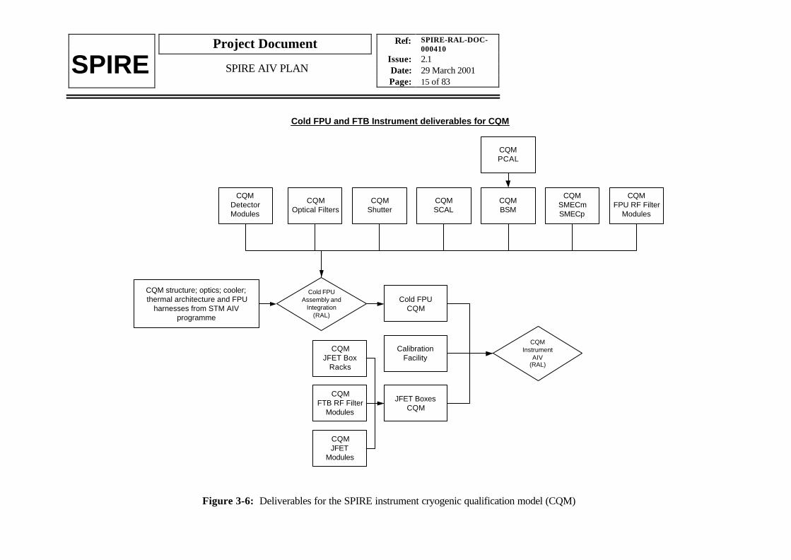
Figure 3-6: Deliverables for the SPIRE instrument cryogenic qualification model (CQM)
CQMFTB RF Filter
Modules
CQMDetectorModules
CQM structure; optics; cooler;thermal architecture and FPU
harnesses from STM AIVprogramme
CQMOptical Filters
CQMBSM
CQMSMECmSMECp
JFET BoxesCQM
CQMShutter
CQMPCAL
CQMSCAL
Cold FPU and FTB Instrument deliverables for CQM
Cold FPUAssembly and
Integration(RAL)
Cold FPUCQM
CQMInstrument
AIV(RAL)
CQMFPU RF Filter
Modules
CalibrationFacility
CQMJFET
Modules
CQMJFET Box
Racks

Ref: SPIRE-RAL-DOC-000410
Issue: 2.1Date: 29 March 2001Page: 16 of 83
Project Document
SPIRE SPIRE AIV PLAN
Figure 3-7: Deliverables for the SPIRE instrument proto flight model (PFM)
PFMFTB RF Filter
Modules
PFMDetectorModules
PFMCooler
PFMStructure;
Baffles; 2-Kstraps
PFMOptical Filters
PFMMirrors
PFMBSM
PFMSMECmSMECp
JFET BoxesPFM
300 mKBusbars
PFMShutter
PFMPCAL
PFMSCAL
Cold FPU and FTB Instrument deliverables for PFM
Struture and OpticsIntegration
and Alignment(MSSL/RAL)
Cold FPUAssembly and
Integration(RAL)
Cold FPUPFM
PFMInstrument
AIV(RAL)
PFMFPU RF Filter
Modules
PFMJFET
Modules
PFMJFET Box
Racks
PFMFPU
Harnesses

Ref: SPIRE-RAL-DOC-000410
Issue: 2.1Date: 29 March 2001Page: 17 of 83
Project Document
SPIRE SPIRE AIV PLAN
4. OUTLINE INSTRUMENT AIV SEQUENCE FOR PRE-FLIGHT MODELS
The verification of the flight design of SPIRE will be done using the STM and CQM instrument modelsand the qualification models of the SPIRE sub-systems. In this section an overview of the “pre-flight”instrument model AIV programme is given together with an indication of the system level issues that areaddressed at each stage of the sequence. This is intended as a guide only – the detailed sequencing ofthe integration and test of the instrument models is given in subsequent sections.
Figures 4-1 through 4-3 show an outline integration and test sequence for the instrument models. Givenalongside the activities for each model are the systems issues that will be verified on each model. Someof these appear in more than one place indicating that different aspects of the systems design will betested on different instrument and sub-system models.
Once the STM testing has been completed, the QM sub-systems can use any results necessary fromthe STM testing in their development programme which, it is assumed, will largely overlap theinstrument level STM/CQM programme leading to a CDR at the end of the CQM programme. At thispoint all the system and sub-system design issues must have been addressed and the final design for thePFM can be confirmed. In fact it will be possible to confirm the design for some sub-systems, thestructure (except for straylight concerns); the cooler and the mirrors, at the end of the STM programme.

Ref: SPIRE-RAL-DOC-000410
Issue: 2.1Date: 29 March 2001Page: 18 of 83
Project Document
SPIRE SPIRE AIV PLAN
Figure 4-1: Outline STM integration and test sequence showing which system level issuesare addressed at each stage.
STMparts
STMassembly includingoptical alignment
Instrument level integrationSub-system mechanical interfacesIntegration and alignmentOptical designInstrument optical performanceSub-system optical interfaces
STM Cold Testingin facility cryostat
Optical designInstrument optical performanceMechanical interface withFIRST systemOptical interface to FIRSTsystemSub-system optical interfacesThermal performanceThermal interface to FIRSTsystemSub-system thermal interfacesInstrument to ground facilityinterfaces
STM Warm Vibration
Mechanical frequency responseAbility to withstand launchenvironmentHarness mechanical frequencyresponse and routing?
STM Cold Vibration
Mechanical frequency responseAbility to withstand launchenvironmentQualification test of instrumentstructureHarness mechanical frequencyresponse and routing?
STMDe-integration
To Sub-systemQual Models
andCQM

Ref: SPIRE-RAL-DOC-000410
Issue: 2.1Date: 29 March 2001Page: 19 of 83
Project Document
SPIRE SPIRE AIV PLAN
Figure 4-2: Outline AVM/QM1 warm electronics units integration and test sequenceshowing which systems issues are addressed at each stage.
Figure 4-3: Outline sub-system qualification model integration and test sequence showingwhich systems issues are addressed at each stage. Not all the systems issues are appropriate
for all sub-systems.
WarmElectronics Units
AVMIntegration and Interface
checks
AVMTesting
Data interface to FIRST systemOn board software definitionSub-system operational and control interfacesSub-system data interfacesOperating mode definitionInstrument commanding definitionFlight commissioning and calibration planLimited EMC testing
Sub-system electrical interfacesWiring tablesElectrical interface to FIRST systemInstrument to ground facility interfaces
To CQM
Sub-systemQual Units
Sub-system QMperformance testing
Sub-system QMenvironmental testing
Mechanical frequency responseAbility to withstand launch environment
Mechanism controlSub-system performance versus environmentSub-system interface compatibility - thermal;electrical; mechanical
To CDR

Ref: SPIRE-RAL-DOC-000410
Issue: 2.1Date: 29 March 2001Page: 20 of 83
Project Document
SPIRE SPIRE AIV PLAN
Figure 4-4: CQM outline integration and test sequence showing which systems issues areaddressed at each stage.
CQM ColdSub-systems
STMStructure
andOptics
CQMSub-system integration
in cold FPUSub-system optical interfaces
CQM instrumentintegration and warm
functional checks
Sub-system electrical interfacesWiring tablesElectrical interface to FIRST systemElectrical groundingOn board software definitionSub-system operational and controlinterfacesSub-system data interfaces
CQM instrument coldtesting
StraylightSub-system optical interfacesMechanism controlDetector performance versus environmentJFET Amplifier performance versus environmentHarness performanceDetector sub-system interface compatibility -thermal; electrical; mechanicalEnd-to-end system performanceElectrical groundingHarness mechanical frequency response androuting?Micro-vibration environment?
AVM
To CDRand SystemLevel Tests
Limited EMC testing: Faraday cage integrity and performance? RF filter performance Harness performanceOperating mode definitionInstrument commanding definitionOn board software definitionSub-system operational and controlinterfacesSub-system data interfacesObserving mode calibration definitionGround commissioning and calibration planFlight commissioning and calibration plan

Ref: SPIRE-RAL-DOC-000410
Issue: 2.1Date: 29 March 2001Page: 21 of 83
Project Document
SPIRE SPIRE AIV PLAN
5. WARM ELECTRONICS AIV
5.1 Overview
Production of the warm electronics units for SPIRE is phased differently to the cold FPU and JFET Boxproduction. This is dictated by the resources available and complex nature of the interfaces betweenthe sub-systems and the warm electronics. In this section we describe the assembly and integration ofthe units that go to make up the warm electronics used to test each instrument model and those whichwill be delivered to ESA.
Each step of the AIV sequence is numbered and the tests are named in bold throughout the section.Whilst an indication of the types of tests that will be carried is given, the detailed procedures for eachtest are the subject of documents covering each test. The correspondence between each test namedhere and the instrument requirements that are verified in each test is given in the appendices. Thecorrespondence between sub-system specifications and tests is dealt with in the subsystem AIV plans.
5.2 AVM Warm Electronics
5.2.1 Capabilities
The AVM warm electronics consists of the AVM model of the DPU and a simulator of the DRCU andcold FPU. It is intended that these will be delivered to ESA.
The DPU will have the full functionality of the flight version but it will be built with commercial gradeparts and will not have redundant systems fitted. It will be identical in external form and fit to the flightunit. This unit will also be used for the testing of the CQM cold FPU and JFET box.
The DRCU simulator will be a computer with interface cards to the DPU that is capable of receivingcommands from the DPU and returning realistic data to mimic the operation of the DRCU; cold FPUand JFET box. Several DRCU simulators will be required at different institutes.
The functionality of the EGSE to be delivered with the AVM is discussed in RD8.
5.2.2 Outline Integration and Verification
Figure 3-1 shows the indicative order of assembly, integration and verification of the instrument AVMand associated EGSE. More detail on the tests to be carried out is given here.
5.2.2.1 DPU Acceptance Tests at IFSI
These will be designed to test the specifications written out in the DPU Specification Document (RD9)and the OBS URD (RD10). Some of the specifications reflect higher level requirements in theInstrument Requirements Document and, therefore, these tests form part of the instrument levelverification. In outline the tests are:
Test low-level interface between the DPU and the CDMS conforms to the appropriateinterface definition

Ref: SPIRE-RAL-DOC-000410
Issue: 2.1Date: 29 March 2001Page: 22 of 83
Project Document
SPIRE SPIRE AIV PLAN
Test high-level interface protocol to S/C (Packet protocols etc)Test high and low speed interfaces between DPU and DRCU – again both hardware andprotocols as given in ICDStatic OBS Functionality – acceptance of commands; TM generation; OBS performancerequirementsOBS Management functions as given in the DPU specification document.
We wish to discover from these tests whether the DPU/OBS can “run” the instrument in all itsoperating modes with the correct data collection; extraction of real time parameters (if necessary);algorithm execution and real time commanding and execution of a command queue from the S/C tosimulate instrument operation – again with correct data collection; TM formatting and transmission toCDMS.
We also need to test the response of the OBS/DPU to various failure conditions both in the DRCU(failure to initialise; PSU failure; interface failure etc) and within one of the sub-systems (loss of SMECposition sensor; loss of drive coils etc). We will also test the autonomy functions of the OBS – that isswitching to SAFE mode in the event of DRCU/sub-system failure of OFF in the event of DPU failure.
In summary the AIV sequence at IFSI will be as follows -:
HS_WE_AIV_1. AVM DPU and OBS acceptance testing at IFSI1.1. The DPU is assembled and integrated at IFSI1.2. The DRCU simulator #1 is delivered to IFSI from Stockholm1.3. The EGSE #1 is delivered to IFSI from RAL (TBC)1.4. The units are connected and basic interface checks are carried out to ensure
compatibility between the DPU; DRCU simulator and the EGSE1.5. The DPU acceptance procedure is carried out to ensure the compatibility of the
unit as delivered from the manufacturer with the SPIRE instrumentrequirements and interface specification (this is the AVM DPU_ACCEPT test)
1.6. The On board Software acceptance procedure is carries out to ensure thecompliance of the DPU and OBS with the OBS user requirements (this is theAVM OBS_ACCEPT test)
1.7. Following the acceptance of the DPU and OBS the DPU is prepared andshipped to RAL. The DRCU simulator #1 and the EGSE #1 remain at IFSI
5.2.2.2 DPU Integration at RAL
At RAL the AVM integration and functional test will be a repeat of a subset of the acceptance testscarried out at IFSI plus a test of running simulated instrument operations .
In summary the AIV sequence at RAL will be:
HS_WE_AIV_2. DPU integration at RAL2.1. The DRCU simulator #2 is delivered to RAL from Stockholm2.2. EGSE#2 is already at RAL2.3. The DPU is received from IFSI2.4. The DPU is integrated with the EGSE and DRCU simulator and basic interface
checks are carried out.2.5. The AVM functional test procedure is carried out. (this is the AVM_FUNC test)

Ref: SPIRE-RAL-DOC-000410
Issue: 2.1Date: 29 March 2001Page: 23 of 83
Project Document
SPIRE SPIRE AIV PLAN
2.6. The DPU AVM is now available for use with the warm electronics to be usedwith the instrument CQM.
5.2.2.3 AVM verification following CQM programme
This AVM DPU will be delivered to ESA together with the DRCU simulator #3 and the EGSE#3 toform the Instrument AVM. This delivery will occur at the end of the instrument CQM programme.Before the Instrument AVM can be delivered it has to be integrated and the AVM verificationprocedures carried out to ensure that any changes to the OBS; the DRCU simulator and/or the EGSEdo not affect the performance of the integrated unit.
In summary the AIV sequence at RAL will be:
HS_AVM_AIV_1. DPU integration at RAL1.1. The DRCU simulator #3 is delivered to RAL from Stockholm1.2. EGSE#3 is already at RAL1.3. The DPU is integrated with the EGSE and DRCU simulator and basic interface
checks are carried out.1.4. The AVM verification test procedure is carried out. (this is the AVM_VER test)
5.3 Warm Electronics for instrument CQM Testing
5.3.1 Capabilities
The warm electronics for the CQM testing consist of the DPU AVM and a qualification model of theDRCU that has full flight functionality but will be built with commercial grade parts and will not haveany redundancy. The QM1 DRCU will be identical in external form and fit to the flight unit. Anengineering model of the warm interconnect harness will also be used. Again this will have externalform and fit identical to the flight unit but will be built with commercial grade parts. In order to verifythe function of the warm electronics for the CQM testing a simulator of the cold FPU and JFET box isrequired to give realistic responses to the DRCU in the absence of the real sub-systems. This FPUsimulator is intended to be as passive as possible, i.e. resistors in place of JFETs; coils; thermistors etc.Only the output from the SMEC position encoder may have to provide some active return in the form ofa sinusoidal signal.
5.3.2 Outline Integration
Figure 3-2 shows the indicative order of assembly and integration tests for the AVM DPU; the QM1DRCU; the QM1 warm interconnect harness and the associated EGSE and FPU simulator. More detailon the steps to be followed is given here.
HS_WE_AIV_3. CQM Warm electronics integration at RAL
3.1. The FPU simulator; the DRCU and the warm interconnect harness will bedelivered to RAL from CEA
3.2. The FPU simulator; the DRCU and the warm interconnect harness will beintegrated with the DPU AVM and EGSE#2 and basic interface checks carriedout

Ref: SPIRE-RAL-DOC-000410
Issue: 2.1Date: 29 March 2001Page: 24 of 83
Project Document
SPIRE SPIRE AIV PLAN
3.3. The warm electronics integration procedures will be carried out (this is the CQMWE_INTG test)
3.4. The warm electronics is now available for integration with the cold FPU andJFET box.
3.5. This set of electronics, including the FPU simulator, will be delivered to ESA aspart of the instrument CQM.
5.4 Warm Electronics Qualification Model
5.4.1 Capabilities
The QM electronics consists of the qualification model DPU; the second qualification model DRCU andthe second qualification model warm interconnect harness. These are identical in function; form and fitto the flight units. They will be built to flight standards with some parts in both the DPU and DRCUbeing “extended range” or commercial grade rather than flight grade. The DPU QM will undergo fullenvironmental and EMC (TBC) testing at IFSI before delivery. The DRCU QM2 will undergo fullenvironmental and EMC testing at CEA before delivery. As the QM FPU simulator has been deliveredto ESA as part of the instrument CQM, another one is required for testing this set of electronics. Thisset of electronics will be used to carry out the majority of instrument PFM tests, however they are notintended for flight and will not be delivered to ESA.
5.4.2 Outline Integration
Figure 3-3 shows the indicative order of assembly and integration for the QM DPU; the QM2 DRCUand the QM2 warm interconnect harness and the associated EGSE and FPU simulator. More detail onthe steps to be followed is given here.
HS_WE_AIV_4. QM Warm electronics integration at RAL4.1. The FPU simulator; the DRCU and the warm interconnect harness will be
delivered to RAL from CEA4.2. The DPU will be delivered to RAL from IFSI4.3. The FPU simulator; the DRCU and the warm interconnect harness will be
integrated with the DPU and EGSE#2 and basic interface checks carried out4.4. The warm electronics integration procedures will be carried out (this is the QM
WE_INTG test)4.5. The warm electronics is now available for integration with the cold FPU and
JFET box.
5.5 PFM Warm Electronics
5.5.1 Capabilities
The PFM electronics consist of the flight models of the DRCU; the warm interconnect harness and theDPU. These are the units intended for flight and have, naturally all the functions required includingredundancy and are fully compliant with the satellite interface requirements. The DRCU; warminterconnect harness and the DPU will have been through environmental acceptance testing beforedelivery to RAL.

Ref: SPIRE-RAL-DOC-000410
Issue: 2.1Date: 29 March 2001Page: 25 of 83
Project Document
SPIRE SPIRE AIV PLAN
5.5.2 Outline Integration
Figure 3-3 shows the indicative order of assembly and integration for the FM DPU; the FM DRCU andthe FM warm interconnect harness and the associated EGSE and FPU simulator. More detail on thesteps to be followed is given here. This set of electronics will be used to carry out the calibration andfunctional performance tests on the PFM instrument. They will be delivered to ESA as part of the PFMinstrument.
HS_WE_AIV_5. PFM Warm electronics integration at RAL5.1. The DRCU and the warm interconnect harness will be delivered to RAL from
CEA5.2. The DPU will be delivered to RAL from IFSI5.3. The FPU simulator; the DRCU and the warm interconnect harness will be
integrated with the DPU and EGSE#2 and basic interface checks carried out5.4. The warm electronics integration procedures will be carried out (this is the PFM
WE_INTG test)5.5. The warm electronics is now available for integration with the cold FPU and
JFET box.
5.6 FS Warm Electronics
5.6.1 Capabilities
It is intended to provide flight spare electronics at board level only. In order to test the electronics theboards will be assembled into the qualification model DRCU and QM DPU frames (QM2 and QMrespectively). Once assembled into the appropriate frames that FS boards will have fully flight likefunction and external form and fit. The QM2 warm interconnect harness will be used for flight sparetesting and there will be no FS warm interconnect harness. The boards will undergo environmentalacceptance testing in the qualification model boxes. It is assumed that the QM2 harness remains atRAL. This set of electronics will be used to carry out the calibration and functional performance testson the FS instrument. The boards within the electronics will be available to replace PFM boards in thePFM instrument in the event of failures during system level AIV.
5.6.2 Outline Integration
Figure 3-4 shows the indicative order of assembly, integration and verification for the QM DPU; theQM2 DRCU and the QM2 warm interconnect harness and the associated EGSE and FPU simulator.More detail on the steps to be followed is given here.
HS_WE_AIV_6. FS Warm electronics integration at RAL6.1. The DRCU boards assembled into the QM2 frame will be delivered to RAL from
CEA6.2. The DPU boards assembled into the QM frame will be delivered to RAL from
IFSI6.3. The FPU simulator; the DRCU and the warm interconnect harness will be
integrated with the DPU and EGSE#2 and basic interface checks carried out6.4. The warm electronics integration procedures will be carried out (this is the FS
WE_INTG test)

Ref: SPIRE-RAL-DOC-000410
Issue: 2.1Date: 29 March 2001Page: 26 of 83
Project Document
SPIRE SPIRE AIV PLAN
6.5. The warm electronics is now available for integration with the cold FPU andJFET box.

Ref: SPIRE-RAL-DOC-000410
Issue: 2.1Date: 29 March 2001Page: 27 of 83
Project Document
SPIRE SPIRE AIV PLAN
6. STM AIV
6.1 Capabilities
The requirements and consequent capabilities of the STM instrument are discussed in RD3. The STMnot an entirely separate model of the instrument as it will consist of the CQM structure; optics and, forpart of the programme, cooler. Mass dummies or engineering models will be used for the other sub-systems. The STM is designed to allow for a verification of the structural and thermal design byconducting a warm vibration test; a cool down and cryogenic thermal test and a cold vibration early onin the instrument AIV programme. The possibility of a radiated EMC susceptibility test on the structurehas also been allowed for in the schedule.
Note – as some parts of the STM will be used for both the CQM and, later, for refurbishment into theflight spare, the STM instrument will be subject to the PA/QA procedures detailed in the SPIRE PAPlan (AD7).
6.2 Test Programme
The following system level design issues will be addressed during the STM AIV programme (repeatedhere from RD3):
Mechanical interface with Herschel systemThe FPU and JFET boxes will have the same form and fit as the PFM and will be interfaced to a mockup of the Herschel optical bench. The ability to accurately place the SPIRE instrument on the Herscheloptical bench and its alignment stability when cooled will be verified.
Optical interface to Herschel systemThe optics fitted to the STM will be of near flight quality. Optical light tests will be carried out to verifythe performance of the optical system with respect to the Herschel telescope optical design.
Thermal interface to Herschel systemThe STM will be placed in a thermal environment in the SPIRE instrument test cryostat that is as closeto the Herschel cryostat as possible. The same temperature levels will be present although the heatcapacity of the various stages may be different. The sorption cooler will be capable of being recycledand these tests will give an indication of whether the specified thermal interface (loads; requiredconductance etc) is correctly specified.
Instrument level integration and alignmentThe STM will give the first opportunity to test and refine the instrument level integration and opticalalignment procedures for the subsequent models.
Optical design and instrument optical performanceThe optical light test programme will be designed to verify the geometrical optical model of theinstrument and, therefore, to give confidence that the instrument optical performance will meet therequirements.
Instrument thermal performance

Ref: SPIRE-RAL-DOC-000410
Issue: 2.1Date: 29 March 2001Page: 28 of 83
Project Document
SPIRE SPIRE AIV PLAN
The instrument thermal balance will be simulated for each operating mode and further diagnostic testswill be devised to allow the instrument Thermal Mathematical Model to be verified. Heaters will beplaced at strategic points in the STM to allow this testing. Of especial importance to the ultimateperformance of the SPIRE instrument will be the behaviour of the 300 mK temperature stage. TheSTM cooler and 300 mK architecture and all the interfaces between the cooler and the detectors will befully flight representative in this respect and there will be at least one thermally representative detectormodule.
Instrument to ground facility interfacesThis will be the first opportunity to check all the physical interfaces between the cold FPU and theinstrument ground facility. This will include checking the form and fit of the test facility cryoharnesswith respect to the FPU and JFET boxes.
Instrument mechanical frequency response and ability to withstand launch environmentA programme of warm vibration will be conducted on the integrated FPU and JFET boxes that willcheck for mechanical resonance and gradually lead to a full qualification level vibration test. If thewarm vibration programme shows no problems, it is expected that a cold vibration of the integrated FPUand JFET boxes will be carried out.
Harness mechanical frequency response and routingThe internal routing of the sub-system harnesses can be confirmed. The routing and support of the FPUto JFET boxes harnesses can be verified both thermally and with respect to the launch environment. Itmay be possible to devise a test programme during the warm vibration that will test the mechanicalresonance of the detector harness assembly (?)
Sub-system mechanical interfacesThe sub-system STMs will be form and fit compliant and will include representative connectors.
Sub-system optical interfacesAny sub-system with an optical interface to the SPIRE instrument will provide a suitable piece of OGSE(that may be removable) or will be compliant with the specified interface.
Sub-system thermal interfacesAll sub-systems that dissipate significant power in the cold FPU or JFET boxes must provide STMs withthe same or similar thermal characteristics and an ability to replicate their expected thermal dissipationunder nominal operating conditions.
6.3 Assembly, Integration and Verification Sequence
Figure 3-5 shows the indicative order of assembly and integration of the STM. In this section theoutline sequence for the AIV programme to be done on the STM FPU and JFET boxes is discussed.This is intimately connected to the structure integration procedure and the alignment plan and is subjectto revision as detailed design of the structure evolves.
HS_WE_AIV_1. Structural Thermal Model1.1. STM FPU Subsystem deliveries
1.1.1. CQM Structure; MGSE and transport container delivery1.1.2. CQM Mirrors delivery

Ref: SPIRE-RAL-DOC-000410
Issue: 2.1Date: 29 March 2001Page: 29 of 83
Project Document
SPIRE SPIRE AIV PLAN
1.1.3. STM Filter delivery1.1.4. STM Cooler Delivery1.1.5. CQM Cooler Delivery1.1.6. STM/CQM Harness Deliveries for each sub-system1.1.7. OGSE Delivery1.1.8. STM FPU RF Filter Modules Delivery1.1.9. BSM Optical dummy delivery1.1.10. SMECm Optical Dummy Delivery1.1.11. STM BDAs Delivery1.1.12. STM Shutter Delivery1.1.13. STM SCAL Delivery1.1.14. STM BSM Delivery1.1.15. STM SMECm Delivery
1.2. STM FPU Alignment 43.5dThe first task in the STM programme is to integrate the mirrors into the structure and toverify the performance of the optical design using visible light both warm and cold. TheFPU structure – notably the optical bench – will require support during integration andalignment. Specialised MGSE will be provided for this task and is considered to be partof the structure delivery. This part of the STM programme is the STM INT_ALIGN test– see RD61.2.1. 3-D Metrology 11d
Here the partially assembled structure with some OGSE fitted is placed into amechanical 3-D metrology machine and the positions of the mirror interfacesare verified and recorded. This is part of the STM ILT_ALIGN test – see RD5
1.2.2. Alignment during integration 20dAfter mechanical metrology the mirrors and other OGSE items are assembledinto the structure and their alignment verified optically using visible light.Integration of the mirrors may involve some re-machining of the mirror mounts –this has been allowed for in the scheduling. Various optical tests are carried outon the integrated structure and optics to verify the performance of the opticaldesign. This is part of the STM INT_ALIGN test – see RD6
1.2.3. Cold Alignment Verification 12.5dOnce the optical alignment and performance has been verified warm, it mustalso be verified cold. The integrated structure; optics and OGSE is placed ontothe Herschel optical bench simulator and thence into the facility cryostat. Theoptical alignment of the instrument with respect to the Herschel optical benchand the internal alignment of the instrument will then be verified cold. This is partof the STM INT_ALIGN test – see RD6
1.3. STM Warm Environmental Test 21dOnce the mirrors have been integrated and the optical alignment and performance hasbeen verified both warm and cold using visible light the OGSE can be removed and thesub-system STMs can be integrated into the structure before the instrument is vibratedwarm. The warm vibration test is carried out to verify overall mechanical responses; togive a reference level for the cold vibration check and to give realistic vibration levels atthe interface locations of the sub-systems. The structure will be instrumented to allowthis to happen. This test is part of the STM ILT_VIB test.1.3.1. Preparation of STM 14d
The OGSE is removed and the sub-system STMs fitted. At this time furtherharnesses will also be fitted and the JFET boxes will be integrated and both theFPU and JFET boxes will be fitted to the vibration jig and the FPU to JFET

Ref: SPIRE-RAL-DOC-000410
Issue: 2.1Date: 29 March 2001Page: 30 of 83
Project Document
SPIRE SPIRE AIV PLAN
harnesses installed. At the end of the integration activities an STM WarmVibration Test Readiness Review will be held.
1.3.2. STM Warm Vibration 5dThe integrated instrument is vibrated warm in three axes. The vibrationprogramme will be designed to build up towards full qualification levels withsuitable checking by resonance searches as the level is increased. This is partof the STM ILT_VIB test.
1.3.3. Post vibration test 5dOnce the vibration has been carried out there will be a series of post vibrationchecks on the optical alignment and the structural integrity. These are part ofthe STM ILT_ALIGN test and the ILT_VIB test
1.3.4. STM Interim Review 3dOnce the STM warm vibration has been carried out the optical and the grossstructural performance can be assessed and any design changes required canbe initiated. If none are required then this can form part of the structure CDRand the go ahead given for the production of the long lead item flight modelstructural components. This will be a formal review to which ESA and primecontractor representatives will be invited.
1.4. STM Cold thermal verification 22dThe FPU will contain the STM cooler at this time. A fully functioning CQM version of thecooler will also be available. In order to proceed with the thermal verification of the FPUdesign this will be fitted into the STM structure and, if not already fitted, the thermaloptical filter at the entrance to the FPU will also now be fitted. The re-integrated FPUwill be placed onto the Herschel optical bench simulator together with the JFET boxesand the harnesses between the FPU and JFET boxes connected. The instrument willat this time also have extra thermistors temporally installed to allow more detailedmonitoring of the FPU temperature during the thermal verification testing. At the end ofthe integration activities an STM Cold Thermal Test Readiness Review will be held.The instrument will then be cooled in the facility cryostat, once cold the STM thermalverification test (STM ILT_THERM) will be carried out.
1.5. STM EMC Testing 16dA radiated susceptibility test on the STM structure together with the JFET boxes andharnesses is a desirable test to verify the integrity of the Faraday cage. This could becarried out at this time by placing an aerial at, or close, to the location of one or more ofthe detectors. This would involve some de-integration and re-integration of the FPUand will only be done if time allows and after a full risk assessment. This is part of theSTM ILT_EMC test
1.6. STM Cold vibration campaign 25dFollowing the EMC test and the re-integration of the STM FPU this instrument is nowready for a cold (<10 K) vibration test at the Herschel common cold vibration facility.The instrument will be prepared; packed and transported to the facility. Before theinstrument is shipped an STM Cold Vibration Test Readiness Review will be held.After instrument has reached the facility and been prepared the three axis vibration testwill be done and the instrument returned to RAL for further testing. Note that this testcan only be done at this time if no severe problems were identified during the warmvibration testing – this is especially true for the cooler as the instrument will contain aworking cooler at this time. This test verifies the mathematical model of the structureand is the qualification test for the SPIRE instrument structure mechanical design.This is part of the STM ILT_VIB test.

Ref: SPIRE-RAL-DOC-000410
Issue: 2.1Date: 29 March 2001Page: 31 of 83
Project Document
SPIRE SPIRE AIV PLAN
1.7. STM Cold verification test 15.5dFollowing the cold vibration test the instrument thermal performance will be tested oncemore in the facility cryostat. The instrument will be unpacked; integrated onto theHerschel optical bench simulator and placed into the test cryostat. The thermalverification test will be repeated and some form of optical alignment test (TBD) will alsobe carried out. This is part of the STM ILT_THERM and ILT_ALIGN tests.
1.8. STM De-Integration 6dFollowing the completion of the cold vibration and final cold verification the STM AIVprogramme is complete. The sub-system STMs can now be removed and thestructure; optics and cooler be made available for use on the CQM.
1.9. STM Post Test Review 6dAt the conclusion of the STM programme a review of the instrument performance thusfar will be conducted. Any design changes necessary for the flight model will beidentified and initiated. This will be the CDR for the cooler; the thermal design of theinstrument and the completion of the CDR for the structural design of the instrument.This will be a formal review to which ESA and prime contractor representatives will beinvited.

Ref: SPIRE-RAL-DOC-000410
Issue: 2.1Date: 29 March 2001Page: 32 of 83
Project Document
SPIRE SPIRE AIV PLAN
7. CQM AIV
7.1 Capabilities
The full capabilities required of the instrument CQM are discussed in RD4. The instrument level CQMprogramme is designed to allow the performance and functionality of the instrument design to be fullyexplored and characterised ahead of the flight model. It is not intended that the CQM be used forenvironmental verification (i.e. it will not be subjected to vibration tests) and therefore the sub-systemsprovided for the CQM need not have full flight representation in terms of flight quality components,although they must conform as closely as possibly to the performance specifications.
Note – as some parts of the CQM will be used for refurbishment into the flight spare, the CQMinstrument will be subject to the PA/QA procedures detailed in the SPIRE PA Plan (AD7).
7.2 Test Programme
The following system level design issues will be addressed during the CQM AIV programme (repeatedhere from RD4):
Electrical interface to Herschel satelliteThe cryoharness for the instrument test facility will simulate the Herschel cryoharness as closely aspossible. The CQM test programme will test all aspects of the electrical interfaces between the SPIREcold units and the cryoharness. The CQM warm electronics units will be entirely flight representativebar the use of flight quality components and the presence of cold redundant circuitry. The electricalinterfaces between SPIRE and the Herschel satellite will be verified in a more realistic operatingsituation compared to the tests carried out on the AVM (see AVM Requirements Document)
Electrical groundingThe CQM will offer the first opportunity to have an all up test of the instrument grounding scheme underrealistic operating conditions. Any excess noise in the detection system can be quickly identified andtrouble shooting undertaken.
Limited EMC testing:The CQM will enable us to determine whether the proposed method providing the Faraday cage offerssufficient protection against radiated EMI in the laboratory environment. Although it will be verydifficult to be quantitative in this, because the test cryostat environment is very different from theHerschel cryostat, it may be possible to have some dedicated qualitative tests to probe for sensitivity atparticular frequencies. It will be possible to do some conducted susceptibility tests to check theperformance of the RF filtering and the cryoharness.
Operations and SoftwareThe CQM will have all the cold sub-systems operational. Although they may not be fully flightrepresentative in terms of thermal dissipation or ability to withstand vibration, they will have a scientificperformance equivalent or nearly equivalent tot he flight sub-systems. This will allow us to test andcharacterise the behaviour of the instrument and give much better definition to the instrumentcommanding scheme and the real-time control aspects of the on board software. We will also be able

Ref: SPIRE-RAL-DOC-000410
Issue: 2.1Date: 29 March 2001Page: 33 of 83
Project Document
SPIRE SPIRE AIV PLAN
to start to define better the operating modes for the instrument and the methods of calibration that willbe employed during observations.
Having an operational instrument will also allow the finalisation the ground commissioning and calibrationplans and procedures and a start to be made on the in-flight commissioning and calibration plan.
OpticalThe CQM will be capable of allowing the far infrared and sub-mm optical performance of theinstrument to be characterised to some extent and the straylight performance of the instrument in tototo be evaluated. This will complete the instrument optical alignment plan.
End-to-end system performanceThe scientific capabilities of the instrument will be tested for the first time. This end-to-end testing willbe the most important feature of the CQM test programme as it will tell us what the real capabilities ofthe flight instrument will be for the first time and, if things are wrong, allow us to adjust the PFM finaldesign.
Electromechanical SystemAs it is not required that the mechanisms are completely flight compatible only a limited amount ofrealistic testing on the two mechanisms may be possible. However things that can be verified will bewhether there is any exported micro-vibration that will trouble the detectors; whether the shutter designworks reliably and whether the control of the BSM and SMEC is really sufficient for the scientificperformance of the instrument.
Radiation Detection SystemThis will be the first time that representative detector arrays have been integrated with the cooler and300 mK hardware with all the correct temperature stages present. Extensive testing of the arrayperformance under realistic operating conditions (including mimicking the background loading from thetelescope) will be carried out to fully characterise the behaviour of the radiation detection system. Testswill also be conducted to characterise the performance of the various elements of the radiation detectionsystem (arrays; JFETs; warm electronics etc) under different environmental conditions – we will beable to change the loading on the detectors and the temperatures of the various stages.
Also all the detector sub-system interfaces will be able to be verified and we will gain some indicationthat the cryoharness specification is adequate.
Instrument Thermal PerformanceAlthough the STM will have tested most of the thermal performance aspects of the SPIRE instrument,the fact that the CQM has real operation mechanisms; detectors; JFET amplifiers and the correctoptical filtering scheme, means that the thermal performance of the instrument can be evaluated in amore realistic environment. In particular, the performance of the 300 mK temperature stage will bemuch more critically examined as there will be real bolometers present.
Sub-system interfacesThe CQM will give final verification of the sub-system optical; electrical; operational; control and datainterface definitions.

Ref: SPIRE-RAL-DOC-000410
Issue: 2.1Date: 29 March 2001Page: 34 of 83
Project Document
SPIRE SPIRE AIV PLAN
7.3 Assembly, Integration and Verification Sequence
HS_INST_AIV_2: Cryogenic Qualification Model2.1. CQM FPU Subsystem Deliveries
It is assumed that the de-integrated STM instrument will already contain the optics; thecooler and 300 mK thermal system and most if not all of the sub-system electricalharnesses. The following units are required for the CQM instrument.2.1.1. CQM SMECm Delivery2.1.2. CQM BDAs Delivery2.1.3. CQM SCAL Delivery2.1.4. CQM Filters, Dichroics and Beamsplitters Delivery2.1.5. CQM FPU RF Filter Modules Delivery (it is possible that these were delivered for
the STM and that, therefore, there are no STM FPU RF Filters)2.1.6. CQM Shutter Delivery2.1.7. CQM BSMm Delivery
2.2. CQM FPU IntegrationThe design of the SPIRE instrument is such that the units mounted from the twodetector boxes need to be integrated and the connections to the 300 mK busbars madebefore that boxes are mounted into the structure. At this time the alignment of thedetector arrays with respect to the detector boxes will also be verified and the dichroicsand filters will be mounted. As with the STM, all FPU integration will take place in aclean area and will require specialised MGSE. The MGSE for holding the structureduring integration is the same as that used for the STM. Any further MGSE required forsub-system integration is considered to be part of the sub-system delivery.2.2.1. Photometer Detector Box Integration 4d
A fully functional photometer long wavelength array will be fitted and twothermally and mechanically representative BDAs will be fitted into the mediumwavelength and short wavelength locations. The dichroics will be fitted eventhough their alignment cannot be verified; the total spectral bandpass of theinstrument needs to be representative.
2.2.2. Spectrometer Detector Box Integration 3dA fully functional spectrometer long wavelength array will be fitted and athermally and mechanically representative BDA fitted to the short wavelengthchannel. The filters will be fitted in both locations.
2.2.3. Detector Box Integration onto Structure 7.5dTo verify the detector box alignment after mounting onto the structure the BSMand SMECm optical dummies may have to be present. It is possible that thealignment of the boxes can be done using reference cubes; if this is the casethen the BSM and SMECm optical dummies may not need to be integrated.Once the detector boxes are physically mounted the detector harnesses can berouted and affixed to the detector boxes. This must be done carefully to ensuregood thermal contact and to avoid the possibility of microphonic interference.
2.2.4. Sub-system integration 9dWith the detector boxes in place the other sub-systems; any straylight bafflesand the rest of the optical filters can be integrated onto the SPIRE optical bench.The order of the integration and the alignment verification procedures are TBD.Once the sub-systems have been integrated and their harnesses connected a

Ref: SPIRE-RAL-DOC-000410
Issue: 2.1Date: 29 March 2001Page: 35 of 83
Project Document
SPIRE SPIRE AIV PLAN
warm functional test may be carried out to ensure electrical integrity before theinstrument covers can be fitted. This is part of the CQM ILT_INTG test.
2.3. CQM FTB Integration 8dIn parallel with the integration of the FPU the JFET modules; JFET box RF filter unitsand the back harness can be integrated into the JFET box structures to form the FTBunits: FTBp and FTBs. The back harness and structures are re-used from the STMprogramme. It may be that some if not all of the JFET modules used for the STMprogramme are fully functioning. Be that as it may the JFET modules to be integratedinto the CQM FTB’s must be fully functioning to allow the complete check out of theCQM warm electronics units. Following assembly of the FTB’s a warm functionalcheck will be done to ensure electrical integrity – this is part of the CQM ILT_INTG test.
2.4. FPU/FTB Integration with FOB Sim. 2dWith both the FPU and FTB’s now integrated they can be mounted onto the plate thatforms the Herschel Optical Bench simulator. The alignment between the FPU and theHerschel optical bench simulator is verified using the alignment references. Theharnesses between the FPU and the FTB’s are connected and affixed to the mountingpoints on the FTB’s. A warm functional test may be carried out (?) to verify electricalintegrity – this would form part of the CQM ILT_INTG test.
2.5. CQM Warm Electronics Integration (HS_WE_AIV_3)In parallel to the FPU/FTB integration the CQM warm electronics will be integrated andfunctionally checked as discussed in section 5.3.
2.6. CQM Verification2.6.1. Instrument integration into Cryostat I 4d
The cold units mounted on the Herschel optical bench simulator will beintegrated into the facility cryostat and the harnesses attached. The externalharness will be attached to the warm electronics units. A warm functional testwill be conducted to ensure the electrical and operational integrity of theintegrated CQM instrument. This is the CQM ILT_WFT test.
2.6.2. CQM Test Readiness Review 3dA review will be held prior to the commencement of the instrument cooldown toconfirm that all systems are functioning correctly and that the test plan andprocedures are correctly established. This will be a formal review to which ESAand prime contractors will be invited.
2.6.3. Instrument Cold Test I 14dAssuming no major deficiencies are identified in the integration or test readinessthe cryostat will be evacuated and the cold instrument units cooled to theiroperating temperature. One the operating temperature has been reached acold functional test will be conducted followed by a thermal verification test.This will be more detailed than the one done for the STM as the instrument nowcontains working sub-systems. During the thermal verification test the coolerwill be recycled and it will be possible to start operation of the detectors. A coldfunctional test of the detectors will then be carried out. Assuming all is well withthe detector operation the final part of the instrument alignment verification canbe completed using far infrared and sub-millimetre radiation via the telescopesimulator. These tests are the CQM ILT_CFT test; the CQM ILT_THER testand the CQM ILT_ALIGN test.
2.6.4. Detector Swap Warmup 21dProvision is made in the CQM schedule to bring the cold units back to ambienttemperature at this stage. This is primarily to allow the flightspare spectrometershort wavelength BDA to be integrated to allow the performance of the FTS to

Ref: SPIRE-RAL-DOC-000410
Issue: 2.1Date: 29 March 2001Page: 36 of 83
Project Document
SPIRE SPIRE AIV PLAN
be fully evaluated. However even is this unit were not available it is felt prudentto plan for a second warmup and cool cycle to allow any integration or operationproblems that might have arisen to be solved. The cryostat will be warmed up;the cold units removed (still attached to the Herschel optical bench simulator)and the FPU removed from optical bench simulator and partially de-integrated toallow the spectrometer short wavelength BDA to be installed. The instrumentwill then be re-assembled and integrated back onto the optical bench simulatorand with the FTB’s. A warm functional test may be carried out (?) to verifyelectrical integrity – this would form part of the CQM ILT_INTG test.
2.6.5. Instrument integration into Cryostat II 3.5dThe cold units on the optical bench simulator will be placed back into the facilitycryostat and the warm functional test repeated. A brief review will be heldbefore the cooldown commences to ensure that all aspects of the instrumentintegration are nominal. This will be a repeat of the CQM ILT_WFT test
2.6.6. Instrument cooldown 5dIf all is well the cold units will be cooled to operating temperature and a coldfunctional test conducted to ensure no problems have occurred. This is arepeat of the CQM ILT_CFT test
2.6.7. Instrument Cold Verification 32dAssuming no problems have arisen, the CQM instrument should now be fullyfunctioning and its basic optical; electrical and thermal functionality will havebeen verified. We are now in a position to carry out more extensiveperformance and operational characterisation tests. The indicative order of thetests to be carried out is: to verify the performance of each sub-system againsta set prescription from the sub-system providers; to run a set of instrumentlevel performance and characterisation tests and finally to run a set of tests toverify and explore the optimum observing mode strategies for the SPIREinstrument. Before warm up commences the standard cold functional test willbe carried out as a final cold health check on the instrument before delivery toESA. Once the instrument is warm a warm functional test will be done as afinal warm health check before delivery to ESA. The cold units will then beremoved from the cryostat. The tests carried out will be the CQM ILT_PERF;the ILT_OPS; the ILT_CFT and the ILT_WFT.
2.7. Critical Design Reviews 2dThe instrument level test and verification procedures on the CQM instrument are nowcomplete. In parallel to the instrument level testing the sub-systems have tested theirQualification Models. The results of all qualification testing will be available at this timeand the SPIRE Critical Design Review will be help. This will be a formal review towhich ESA and Prime Contractor representatives will be invited.
2.8. CQM Delivery Preparation 10dThe instrument will be prepared for shipment to ESA and the Acceptance DeliveryPackage (ADP) prepared. At this time any items needed for flight spare use (i.e. thespectrometer short wavelength array) will be removed from the instrument andreplaced by STM’s or QM’s.
2.9. CQM Readiness Review 2dBefore shipment to ESA a readiness review will be help to check the instrument statusand to review the contents of the ADP.
2.10. Delivery of CQM to ESA 0d

Ref: SPIRE-RAL-DOC-000410
Issue: 2.1Date: 29 March 2001Page: 37 of 83
Project Document
SPIRE SPIRE AIV PLAN

Ref: SPIRE-RAL-DOC-000410
Issue: 2.1Date: 29 March 2001Page: 38 of 83
Project Document
SPIRE SPIRE AIV PLAN
8. PFM AIV
8.1 Capabilities
The PFM FPU and JFET Boxes must be fully compliant with the Instrument Requirements Document.The electronics used to test the PFM FPU and JFET Boxes are initially the Qualification Models of theDRCU and DPU. However, in order to fully calibrate the instrument prior to integration in the satellitethe PFM electronics units must be integrated with the FPU and JFET boxes and the calibrationprocedures carried out with the full proto-flight instrument.
8.2 Test Programme
Most of the design requirements on the SPIRE instrument will have been verified on the AVM; STMand CQM instruments and at unit level on the sub-system QM’s. The test programme for the PFM willbe designed to verify that the instrument is capable of meeting its performance requirements and will becapable carry out the defined observing modes. In addition, and most importantly, the AIV programmefor the PFM instrument is geared towards carry out the instrument calibration tests that will fulfil therequirements set out in the Instrument Calibration Requirements Document.
8.3 Assembly and Integration and Verification Sequence
HS_INST_AIV_3: Proto-Flight Model3.1. PFM FPU Deliveries
3.1.1. PFM Structure; MGSE and transport container Delivery3.1.2. PFM Thermal Straps Delivery3.1.3. PFM Mirrors Delivery3.1.4. PFM Cooler Delivery3.1.5. PFM Filters, Dichroics and Beamsplitters Delivery3.1.6. PFM BSMm Delivery3.1.7. PFM SMECm Delivery3.1.8. PFM BDAs Delivery3.1.9. PFM SCAL Delivery3.1.10. PFM Shutter Delivery3.1.11. PFM FPU RF Filter Modules Delivery
3.2. 3-D Metrology 11dThis is a repeat of the process carried out on the STM. Here the partially assembledstructure with some OGSE fitted is placed into a mechanical 3-D metrology machineand the positions of the mirror interfaces are verified and recorded. This is part of thePFM ILT_ALIGN test – see RD53.2.1. Preparation 2d3.2.2. Fit OGSE into detector boxes 1d3.2.3. Fit and align detector mirrors and dichroic mounts 2d3.2.4. Fit detector boxes into structure 1d3.2.5. 3-D metrology 5d
3.3. Alignment during integration 29dAfter mechanical metrology the mirrors and other OGSE items are assembled into thestructure and their alignment verified optically using visible light. Integration of themirrors may involve some re-machining of the mirror mounts – this has been allowed
Ref: SPIRE-RAL-DOC-000410
Issue: 2.1Date: 29 March 2001Page: 39 of 83
Project Document
SPIRE SPIRE AIV PLAN
for in the scheduling. Various optical tests are carried out on the integrated structureand optics to verify the performance of the optical design. At this time the FPU RFfilter modules and sub-system harnesses can be integrated and the PFM cooler willalso be integrated to allow basic thermal checks to be carried during the cold alignmentverification. This is part of the PFM INT_ALIGN test – see RD63.3.1. Structure into GSE and fit OGSE 2d3.3.2. Fit and align mirrors 10d3.3.3. External alignment verification 1d3.3.4. Pupil Quality Verification 1d3.3.5. Image Quality Verification 1d3.3.6. RF Filter Modules and sub-system harness integration 3d3.3.7. Cooler Integration 2d3.3.8. Fit covers and mount on FOB 2d3.3.9. Alignment of SOR wrt FOR 1d3.3.10. Verify image quality and stability 2d
3.4. Cold Alignment and Thermal Checks 20dOnce the optical alignment and performance has been verified warm, it must also beverified cold. The integrated structure; optics and OGSE which is now integrated ontothe Herschel optical bench simulator is placed into the facility cryostat. The opticalalignment of the instrument with respect to the Herschel optical bench and the internalalignment of the instrument will then be verified cold. While the partially integrated FPUis cold basic thermal balamce checks can be carried out and the cooler recyclingchecked out. This is part of the PFM INT_ALIGN and ILT_THER tests3.4.1. Integration into Cryostat 2d3.4.2. Cooldown 4d3.4.3. Cold optical alignment checks 5d3.4.4. Thermal Performance Checks 5d3.4.5. Warmup 3d
3.5. Completion of FPU Integration 27dAssuming no problems are identified with either the optical alignment or basic thermalperformance of the instrument, the rest of the cold sub-systems can be integrated intothe structure. All remaining sub-systems are integrated at this time.3.5.1. De-integrate optical/mass dummies 3d3.5.2. BDAs Integration and Alignment 8d3.5.3. SCAL Integration and Alignment 2d3.5.4. SMECm Integration and Alignment 3d3.5.5. BSMm Integration and Alignment 3d3.5.6. Shutter Integration 2d3.5.7. Filters, Dichroics and Beamsplitters Integration 2d3.5.8. Structure Final Integration 1d
3.6. PFM Instrument Bakeout 5dIt is anticipated that the FPU will be baked out at this time in accordance withHerschel/Planck PA plan requirements.
3.7. PFM FTB Integration 8dIn parallel with the integration of the FPU the JFET modules; JFET box RF filter unitsand the back harness can be integrated into the JFET box structures to form the FTBunits: FTBp and FTBs. Following assembly of the FTB’s a warm functional check willbe done to ensure electrical integrity – this is part of the PFM ILT_INTG test.
3.8. FPU/FTB Integration with FOB Sim. 2dWith both the FPU and FTB’s now integrated they can be mounted onto the plate that

Ref: SPIRE-RAL-DOC-000410
Issue: 2.1Date: 29 March 2001Page: 40 of 83
Project Document
SPIRE SPIRE AIV PLAN
forms the Herschel Optical Bench simulator. The alignment between the FPU and theHerschel optical bench simulator is verified using the alignment references. Theharnesses between the FPU and the FTB’s are connected and affixed to the mountingpoints on the FTB’s. A warm functional test may be carried out (?) to verify electricalintegrity – this would form part of the PFM ILT_INTG test.
3.9. QM Warm Electronics Integration (HS_WE_AIV_4)In parallel to the FPU/FTB integration the QM warm electronics will be integrated andfunctionally checked as discussed in section 5.4.
3.10. PFM Verification 82d3.10.1. Instrument Integration into Cryostat I 4d
The cold units mounted on the Herschel optical bench simulator will beintegrated into the facility cryostat and the harnesses attached. The externalharness will be attached to the warm electronics units. A warm functional testwill be conducted to ensure the electrical and operational integrity of theintegrated PFM instrument. This is the PFM ILT_WFT test.
3.10.2. PFM Test Readiness Review 3dA review will be held prior to the commencement of the instrument cooldown toconfirm that all systems are functioning correctly and that the test plan andprocedures are correctly established. This will be a formal review to which ESAand prime contractors will be invited.
3.10.3. PFM Instrument Cold Tests I 21dAssuming no problems are identified with the instrument integration, the coldunits will be cooled down to operating temperature and the first set of PFM coldtests will be conducted. These will consist of the standard instrument coldfunctional test and a standard instrument basic performance test to give abaseline set of performance figures for comparison after the cold vibration test.Extra time is given to the standard performance test before vibration to allow forany debugging or characterisation of the integrated instrument. The cold unitsof the instrument will be warmed up following the standard instrument test and awarm functional test conducted to give a baseline for comparison after the coldvibration. These are the PFM ILT_CFT; part of the ILT_PERF and theILT_WFT tests.3.10.3.1. Cool down 4d3.10.3.2. Cold Functional Tests I 3d3.10.3.3. Pre-vibration Performance Tests 10d3.10.3.4. Warm Up 3d3.10.3.5. Warm Functional Tests II 1d
3.10.4. PFM Cold Vibration 37dAfter the instrument has been warmed up it will be prepared and packed fordelivery to the cold vibration facility. The cold vibration will be conducted and theinstrument returned to RAL. After return to RAL the cold units will be re-integrated with the Herschel optical bench simulator and the external alignmentverified. This is the PFM ILT_VIB test.3.10.4.1. FPU/FTB Packing and preparation 5d3.10.4.2. Ship FPU/FTB to Cold Vibration Facility 2d3.10.4.3. Instrument Cold Vibration Campaign 21d3.10.4.4. FPU/FTB Packing and preparation 5d3.10.4.5. Ship FPU/FTB to RAL 2d3.10.4.6. Integrate FPU/FTB onto optical bench sim. 2d

Ref: SPIRE-RAL-DOC-000410
Issue: 2.1Date: 29 March 2001Page: 41 of 83
Project Document
SPIRE SPIRE AIV PLAN
3.10.5. Instrument Integration into Cryostat II 4dThe cold units mounted on the Herschel optical bench simulator will beintegrated into the facility cryostat and the harnesses attached. The externalharness will be attached to the warm electronics units. A warm functional testwill be conducted to ensure the electrical and operational integrity of theintegrated PFM instrument after vibration. This is the PFM ILT_WFT test.
3.10.6. PFM Instrument Cold Tests II 11dThe cold units will be cooled down to operating temperature and the second setof PFM cold tests will be conducted. These will consist of the standardinstrument cold functional test and a standard instrument basic performancetest to compare to the tests conducted before the cold vibration test. Thestandard performance test will be shorter this time. Following these tests theinstrument will be left cold in preparation for the performance and calibrationtests. These are the PFM ILT_CFT; part of the ILT_PERF and the3.10.6.1. Cool Down 4d3.10.6.2. Cold Functional Tests II 3d3.10.6.3. Post-vibration Performance Tests 5d
3.10.7. PFM Post Test Review 2dThe environmental verification of the PFM is now complete and a review of theresults will now be held to verify that the instrument is capable of withstandinglaunch. This will be a formal review to ESA and Prime Contractorrepresentatives will be invited.
3.11. PFM Warm Electronics Integration (HS_WE_AIV_5)In parallel to the PFM verification programme the PFM warm electronics will bedelivered and integrated and functionally checked as discussed in section 5.5.
3.12. PFM Instrument Calibration 45dThe PFM instrument is now fully integrated and the performance characterisation andcalibration of the flight configuration can be carried out. The first test will be a repeat ofthe instrument cold functional test to give a baseline characterisation of the instrumentfunctions. The warm electronics units will then be placed in a thermally controlledenvironment to allow the performance of the instrument to be characterised with thewarm electronics operating over the expected temperature range of the SVM. Oncethis has been done an extensive series of instrument performance and calibration testswill be carried out. Finally a cold functional test will be conducted before the instrumentis warmed up to give a baseline for comparison after integration in the Herschelcryostat. After the cold units have been warmed up a warm functional test will becarried to give a warm characterisation baseline. These are the PFM ILT_CFT; theILT_PERF; the ILT_CAL and the ILT_WFT.3.12.1. Cold Functional Tests III 3d3.12.2. Warm Electronics Thermal Range Tests 5d3.12.3. Calibration and performance verification 30d3.12.4. Cold Functional Test IV 3d3.12.5. Warm Up 3d3.12.6. Warm Functional Test III 1d
3.13. PFM Delivery Preparation 14dOnce the cold units have been warmed up and removed from the cryostat theinstrument will be prepared and packed ready for shipment to ESA. The ADP will alsobe compiled at this time.3.13.1. De-integrtaion of FPU and FTB from optical bench sim 2d3.13.2. Mass properties Measurement 2d

Ref: SPIRE-RAL-DOC-000410
Issue: 2.1Date: 29 March 2001Page: 42 of 83
Project Document
SPIRE SPIRE AIV PLAN
3.13.3. Packing and shipment 10d3.13.4. Preparation of Delivery Data Package 10d
3.14. PFM Readiness Review 2dThe instrument level AIV sequence for the SPIRE PFM is now complete. A deliveryreadiness review will be held to examine the performance and calibration status of theinstrument and the contents of the ADP prior to delivery to ESA. This will be a formalreview to which ESA and Prime Contractor representatives will be invited.
3.15. Delivery of PFM to ESA 0d

Ref: SPIRE-RAL-DOC-000410
Issue: 2.1Date: 29 March 2001Page: 43 of 83
Project Document
SPIRE SPIRE AIV PLAN
9. FS AIV
9.1 Capabilities
The FS FPU and JFET Box will be identical to the PFM. The electronics used to test the FS FPU andJFET Box consist of boards the are identical to the PFM electronics assembled into the qualificationmodel frames.
9.2 Outline Assembly and Integration and Verification
The FS AIV will be identical to the PFM AIV except steps 3.10.4 where we plan only a warm vibrationand step 3.11 which is not required as the calibration and functional characterisation will be carried outwith the electronics that will ultimately be used with the flightspare.


Ref: SPIRE-RAL-DOC-000410
Issue: 2.1Date: 29 March 2001Page: 45 of 83
Project Document
SPIRE SPIRE AIV PLAN
10. APPENDIX: REQUIREMENTS MATRIX
Cross reference matrix between instrument requirements; qualification requirements and the test that will be carried out on each model – this is held as tables in an MSAccess database.
Reference Description Verification Method Model 1
Model 2
Model 3
Model 4
Test ID1 Test ID2 Test ID3 Test ID4 Test ID5
IRD-AUT-R01 The SPIRE instrument shall havea defined safe mode.
Design analysis N/A N/A
IRD-AUT-R02 The SPIRE instrument shalldefine housekeepingparameters to be used forautonomous health and safetymonitoring
Design analysis N/A N/A
IRD-AUT-R03 The SPIRE instrument shallprovide a method of monitoringthe defined housekeepingparameters and takingappropriate action in the case oferror or failure.
Design analysis AVM functionaltests
AVM AVM_FUNC
IRD-AUT-R04 The SPIRE instrument shallprovide a method of alerting theS/C CDMS of any failure requiringthe instrument to be controlled bythe CDMS (e.g. switched off ).
Design analysis AVM functionaltests
AVM AVM_FUNC
IRD-AUT-R05 The instrument shallcontinuously monitor the integrityof the on-board software andtake appropriate action in case oferror.
Design analysis AVM functionaltests
AVM AVM_FUNC
IRD-AUT-R06 The instrument shall monitor theoperational status of the
Design analysis AVM functionaltests
AVM AVM_FUNC

Ref: SPIRE-RAL-DOC-000410
Issue: 2.1Date: 29 March 2001Page: 46 of 83
Project Document
SPIRE SPIRE AIV PLAN
Reference Description Verification Method Model 1
Model 2
Model 3
Model 4
Test ID1 Test ID2 Test ID3 Test ID4 Test ID5
instrument on-board computersand take appropriate action incase of error.
IRD-BSMP-R01 Maximum throw in chop axis Design analysis Instrument levelperformance tests
CQM PFM ILT_PERF
IRD-BSMP-R02 Maximum throw in jiggle axis Design analysis Instrument levelperformance tests
CQM PFM ILT_PERF
IRD-BSMP-R03 Minimum step in both axis Design analysis Instrument levelperformance tests
CQM PFM ILT_PERF
IRD-BSMP-R04 Frequency of chop Design analysis Instrument levelperformance tests
CQM PFM ILT_PERF
IRD-BSMP-R05 Holding Position Design analysis Instrument levelperformance tests
CQM PFM ILT_PERF
IRD-BSMP-R06 Stability Design analysis Instrument levelperformance tests
CQM PFM ILT_PERF
IRD-BSMP-R07 Position Measurement Design analysis Instrument levelperformance tests
CQM PFM ILT_PERF
IRD-BSMP-R08 Duty Cycle Design analysis Instrument levelperformance tests
CQM PFM ILT_PERF
IRD-BSMP-R09 Volume envelope Design analysis Instrument levelintegration verification Subsystemacceptance data package
STM CQM ILT_INTG
IRD-BSMP-R10 Operating temperature Design analysis Instrument levelwarm functional test Instrumentlevel cold functional tests
CQM PFM ILT_WFT ILT_CFT
IRD-BSMP-R11 Thermal isolation Design analysis Instrument levelthermal verification Instrumentlevel performance tests
STM CQM ILT_THER ILT_PERF
IRD-BSMP-R12 Cold power dissipation Design analysis Instrument levelcold functional test
CQM PFM ILT_CFT
IRD-CALP-R01 Nominal operating output Design Analysis Instrument levelperformance tests
CQM PFM ILT_PERF
IRD-CALP-R02 Operating range Design Analysis Instrument level CQM PFM ILT_PERF

Ref: SPIRE-RAL-DOC-000410
Issue: 2.1Date: 29 March 2001Page: 47 of 83
Project Document
SPIRE SPIRE AIV PLAN
Reference Description Verification Method Model 1
Model 2
Model 3
Model 4
Test ID1 Test ID2 Test ID3 Test ID4 Test ID5
performance testsIRD-CALP-R03 Equivalent obscuration of
aperture through BSM mirrorDesign Analysis Instrument levelperformance tests
CQM PFM ILT_PERF
IRD-CALP-R04 Speed of response Design Analysis Instrument levelperformance tests
CQM PFM ILT_PERF
IRD-CALP-R05 Repeatability Design Analysis Instrument levelperformance tests
CQM PFM ILT_PERF
IRD-CALP-R06 Operation Design analysis Instrument leveloperations tests
CQM PFM ILT_OPS
IRD-CALP-R07 Frequency Design analysis Instrument leveloperations tests
CQM PFM ILT_OPS
IRD-CALP-R08 Interface Design analysis N/A N/AIRD-CALP-R09 Volume envelope Design analysis Instrument level
integration verification Subsystemacceptance data package
STM CQM ILT_INTG
IRD-CALP-R10 Thermal isolation Design analysis Instrument levelthermal verification Instrumentlevel cold functional test
STM CQM PFM ILT_THER ILT_CFT
IRD-CALP-R11 Operating temperature Design analysis Instrument levelcold functional test
CQM PFM ILT_CFT
IRD-CALP-R12 Cold power dissipation Design analysis Instrument levelcold functional test Instrumentlevel operations tests
CQM PFM ILT_CFT ILT_OPS
IRD-CALP-R14 Operating voltage Design analysis N/A N/AIRD-CALP-R15 Redundancy Design analysis (FMECA) N/A N/AIRD-CALS-R01 Radiated spectrum: Design analysis Instrument level
performance testsCQM PFM ILT_PERF
IRD-CALS-R02 Beam pattern Design analysis Instrument levelperformance tests
CQM PFM ILT_PERF
IRD-CALS-R03 Adjustability: Design analysis Instrument levelcold functional tests Instrumentlevel performance tests
CQM PFM ILT_CFT ILT_PERF
IRD-CALS-R04 Uniformity Design analysis Instrument level CQM PFM ILT_PERF

Ref: SPIRE-RAL-DOC-000410
Issue: 2.1Date: 29 March 2001Page: 48 of 83
Project Document
SPIRE SPIRE AIV PLAN
Reference Description Verification Method Model 1
Model 2
Model 3
Model 4
Test ID1 Test ID2 Test ID3 Test ID4 Test ID5
performance testsIRD-CALS-R05 Repeatability and drift Design analysis Instrument level
performance testsCQM PFM ILT_PERF
IRD-CALS-R06 Operation Design analysis Instrument leveloperations tests
CQM PFM ILT_OPS
IRD-CALS-R07 Number of operations Design analysis Subsystemacceptance data package
N/A N/A
IRD-CALS-R08 Operating Voltage Design analysis N/A N/AIRD-CALS-R09 Power dissipation in the focal
planeDesign analysis Instrument levelcold functional test Instrumentlevel operations tests
CQM PFM ILT_CFT ILT_OPS
IRD-CALS-R11 Envelope Design analysis Instrument levelintegration verification Subsystemdelivery data package
STM CQM ILT_INTG
IRD-CALS-R12 Thermal Isolation Design analysis Instrument levelthermal verification Instrumentlevel cold functional test
STM CQM PFM ILT_THER ILT_CFT
IRD-CALS-R13 Operating Temperature Design analysis Instrument levelcold functional test
CQM PFM ILT_CFT
IRD-CALS-R14 Redundancy Design analysis (FMECA) N/A N/AIRD-CALS-R15 Thermometry Design analysis N/A N/AIRD-CMD-R01 The instrument shall be capable
of accepting telecommandpackets from the CDMS atspeeds up to the maximum ratedelivered by the CDMS withoutloss.
Design analysis AVM functionaltests
AVM AVM_FUNC
IRD-CMD-R02 The instrument shall validateeach telecommand packet as itis received.
Design analysis AVM functionaltests
AVM AVM_FUNC
IRD-CMD-R03 The instrument shall verifyexecution of the telecommandsin each packet.
Design analysis AVM functionaltests
AVM AVM_FUNC

Ref: SPIRE-RAL-DOC-000410
Issue: 2.1Date: 29 March 2001Page: 49 of 83
Project Document
SPIRE SPIRE AIV PLAN
Reference Description Verification Method Model 1
Model 2
Model 3
Model 4
Test ID1 Test ID2 Test ID3 Test ID4 Test ID5
IRD-CMD-R04 The instrument shall report theresult of all telecommandvalidation/verification in telemetry
Design analysis AVM functionaltests
AVM AVM_FUNC
IRD-CMD-R05 The instrument shall providecommands to allow control of allindividual devices (e.g. switch orlatch) within the instrument.
Design analysis AVM functionaltests
AVM AVM_FUNC
IRD-CMD-R06 All commands to individualdevices shall explicitly set thestate of the device
Design analysis AVM functionaltests
AVM AVM_FUNC
IRD-CMD-R07 The action of all commandsaffecting an individual deviceshall be verifiable by anindependent parameter availablein the nominal housekeepingpacket.
Design analysis AVM functionaltests
AVM AVM_FUNC
IRD-CMD-R08 The instrument shall providecommands to execute thefunctions required to implementthe instrument operating modes
Design analysis AVM functionaltests Instrument level operationstests
AVM CQM PFM FS AVM_FUNC
ILT_OPS
IRD-CMD-R09 The instrument shall provide thefacility to define and executeprocedure commands.
Design analysis AVM functionaltests
AVM AVM_FUNC
IRD-CMD-R10 The instrument shall providecommands to modify theexecution sequence ofcommands.
Design analysis AVM functionaltests
AVM AVM_FUNC
IRD-CMD-R11 The instrument shall providecommands to allow identificationof the steps within anobservation.
Design analysis AVM functionaltests Instrument level operationstests
AVM CQM PFM FS AVM_FUNC
ILT_OPS
IRD-CMD-R12 The instrument shall providecommands to modify data
Design analysis AVM functionaltests
AVM AVM_FUNC

Ref: SPIRE-RAL-DOC-000410
Issue: 2.1Date: 29 March 2001Page: 50 of 83
Project Document
SPIRE SPIRE AIV PLAN
Reference Description Verification Method Model 1
Model 2
Model 3
Model 4
Test ID1 Test ID2 Test ID3 Test ID4 Test ID5
values/tables held in theinstrument memory.
IRD-CMD-R13 The instrument shall providecommands to enable on-boardsoftware maintenance
Design analysis AVM functionaltests
AVM AVM_FUNC
IRD-COOL-R01 Temperature at the detectors Design analysis Instrument levelthermal verification
STM CQM PFM ILT_THER
IRD-COOL-R02 Operating temperature control Design analysis Instrument levelthermal verification
STM CQM PFM ILT_THER
IRD-COOL-R03 Temperature drop acrossthermal link between detectorsand evaporator cold tip
Design analysis Instrument levelthermal verification
STM CQM PFM ILT_THER
IRD-COOL-R04 Temperature drift Design analysis Instrument levelthermal verification
STM CQM PFM ILT_THER
IRD-COOL-R05 Temperature fluctuations at theevaporator cold tip
Design analysis Instrument levelthermal verification
STM CQM PFM ILT_THER
IRD-COOL-R06 System low frequencytemperature stability
Design analysis Instrument levelthermal verification
STM CQM PFM ILT_THER
IRD-COOL-R07 Heat lift at evaporator cold tip Design analysis Instrument levelthermal verification
STM CQM PFM ILT_THER
IRD-COOL-R08 Hold time Design analysis Instrument levelthermal verification
STM CQM PFM ILT_THER
IRD-COOL-R09 Recycle time Design analysis Instrument levelthermal verification
STM CQM PFM ILT_THER
IRD-COOL-R10 Mechanical interface Design analysis Instrument levelintegration verification
STM ILT_INTG
IRD-COOL-R11 Thermal Interface with Herschelcryostat
Design analysis Instrument levelthermal verification
STM CQM PFM ILT_THER
IRD-COOL-R12 Parasitic thermal load onto Hebath during cold operation
Design analysis Instrument levelthermal verification
STM CQM PFM ILT_THER
IRD-COOL-R13 Time averaged thermal load ontoHe bath for 48 hour cycle
Design analysis Instrument levelthermal verification
STM CQM PFM ILT_THER
IRD-COOL-R15 Maximum envelope Design analysis Instrument level STM ILT_INTG

Ref: SPIRE-RAL-DOC-000410
Issue: 2.1Date: 29 March 2001Page: 51 of 83
Project Document
SPIRE SPIRE AIV PLAN
Reference Description Verification Method Model 1
Model 2
Model 3
Model 4
Test ID1 Test ID2 Test ID3 Test ID4 Test ID5
integration verification Subsystemacceptance data package
IRD-COOL-R18 Thermometers Design analysis N/A N/AIRD-COOL-R19 Gas gap heat switches Design analysis (FMECA) N/A N/AIRD-COOL-R20 Ground Operation Subsystem verification
programmeN/A N/A
IRD-DATA-R01 All data transferred between theCDMS and the instrument shallbe contained in packetsconforming to the ESA PacketUtilisation Standard (RD4)
Design analysis AVM functionaltests
AVM AVM_FUNC
IRD-DATA-R02 The instrument shall provide allmandatory packet handlingservices defined for the mission.
Design analysis AVM functionaltests
AVM AVM_FUNC
IRD-DATA-R03 The instrument shall be capableof buffering data generatedduring an observation.
Design analysis AVM functionaltests
AVM AVM_FUNC
IRD-DATA-R04 The instrument shall be capableof reducing the average data rateto the CDMS to 20kbps.
Design analysis AVM functionaltests
AVM AVM_FUNC
IRD-DATA-R05 The packing of science data intoscience data packets shallminimise loss of information ifpacket is lost or corrupted.
Design analysis AVM functionaltests Instrument level operationstests
AVM CQM PFM FS AVM_FUNC
ILT_OPS
IRD-DETP-R01 Detective Quantum Efficiency at 2Hz at nominal incident powerlevels
Design analysis Instrument levelperformance tests
CQM PFM ILT_PERF
IRD-DETP-R02 Time constant Design analysis Instrument levelperformance tests
CQM PFM ILT_PERF
IRD-DETP-R03 Uniformity Design analysis Instrument levelperformance tests
CQM PFM ILT_PERF
IRD-DETP-R04 Yield (good pixels) Design analysis Subsystemacceptance data package
N/A N/A

Ref: SPIRE-RAL-DOC-000410
Issue: 2.1Date: 29 March 2001Page: 52 of 83
Project Document
SPIRE SPIRE AIV PLAN
Reference Description Verification Method Model 1
Model 2
Model 3
Model 4
Test ID1 Test ID2 Test ID3 Test ID4 Test ID5
IRD-DETP-R05 Electrical crosstalk for nearneighbour pixels.
Design analysis Instrument levelcold functional tests Instrumentlevel performance tests
CQM PFM ILT_CFT ILT_PERF
IRD-DETP-R06 Electrical crosstalk any pair ofpixels
Design analysis Instrument levelcold functional tests Instrumentlevel performance tests
CQM PFM ILT_CFT ILT_PERF
IRD-DETP-R07 Detector angular response Design analysis Subsystemacceptance data package
N/A N/A
IRD-DETP-R08 Spectral response Design analysis Instrument levelperformance tests
CQM PFM ILT_PERF
IRD-DETP-R09 Microphonic susceptibility Design analysis Instrument levelperformance tests
CQM PFM ILT_PERF
IRD-DETP-R10 EMI susceptibility Design analysis Instrument levelEMC tests Instrument levelperformance tests
CQM PFM ILT_EMC ILT_PERF
IRD-DETP-R11 Sensitivity to ionising radiation Design analysis Subsystemverification programme
N/A N/A
IRD-DETP-R12 Volume envelope Design analysis Instrument levelintegration verification Subsystemacceptance data package
STM CQM ILT_INTG
IRD-DETP-R13 300 mK thermal load Design analysis Instrument levelthermal verification
STM CQM PFM ILT_THER
IRD-DETP-R14 Mechanical interface Design analysis Instrument levelintegration verification Subsystemacceptance data package
STM CQM ILT_INTG
IRD-DETP-R15 Eigenfrequency of the detectorarray structure
Design analysis Subsystemverification programmeSubsystem acceptance datapackage
N/A N/A
IRD-DETP-R16 Eigenfrequency of the detectorarray structure
Design analysis Subsystemverification programmeSubsystem acceptance datapackage
N/A N/A

Ref: SPIRE-RAL-DOC-000410
Issue: 2.1Date: 29 March 2001Page: 53 of 83
Project Document
SPIRE SPIRE AIV PLAN
Reference Description Verification Method Model 1
Model 2
Model 3
Model 4
Test ID1 Test ID2 Test ID3 Test ID4 Test ID5
IRD-DETS-R01 Detective Quantum Efficiency at20 Hz at nominal incident powerlevels
Design analysis Instrument levelperformance tests
CQM PFM ILT_PERF
IRD-DETS-R02 Time constant Design analysis Instrument levelperformance tests
CQM PFM ILT_PERF
IRD-DETS-R03 Uniformity Design analysis Instrument levelperformance tests
CQM PFM ILT_PERF
IRD-DETS-R04 Yield (good pixels) Design analysis Subsystemacceptance data package
N/A N/A
IRD-DETS-R05 Electrical crosstalk for nearneighbour pixels.
Design analysis Instrument levelcold functional tests Instrumentlevel performance tests
CQM PFM ILT_CFT ILT_PERF
IRD-DETS-R06 Electrical crosstalk any pair ofpixels
Design analysis Instrument levelcold functional tests Instrumentlevel performance tests
CQM PFM ILT_CFT ILT_PERF
IRD-DETS-R07 Detector angular response Design analysis Subsystemacceptance data package
N/A N/A
IRD-DETS-R08 Spectral response Design analysis Instrument levelperformance tests
CQM PFM ILT_PERF
IRD-DETS-R09 Sampling frequency Design analysis Instrument levelwarm functional tests Instrumentlevel performance tests
CQM PFM ILT_WFT ILT_PERF
IRD-DETS-R10 Microphonic susceptibility Design analysis Instrument levelperformance tests
CQM PFM ILT_PERF
IRD-DETS-R11 EMI susceptibility Design analysis Instrument levelEMC tests Instrument levelperformance tests
CQM PFM ILT_EMC ILT_PERF
IRD-DETS-R12 Sensitivity to ionising radiation Design analysis Subsystemverification programme
N/A N/A
IRD-DETS-R13 Volume envelope Design analysis Instrument levelintegration verification Subsystemacceptance data package
STM CQM ILT_INTG
IRD-DETS-R14 300 mK thermal load Design analysis Instrument level STM CQM PFM ILT_THER

Ref: SPIRE-RAL-DOC-000410
Issue: 2.1Date: 29 March 2001Page: 54 of 83
Project Document
SPIRE SPIRE AIV PLAN
Reference Description Verification Method Model 1
Model 2
Model 3
Model 4
Test ID1 Test ID2 Test ID3 Test ID4 Test ID5
thermal verificationIRD-DETS-R15 Mechanical interface Design analysis Instrument level
integration verification Subsystemacceptance data package
STM CQM ILT_INTG
IRD-DSIM-R01 Function Design analysis Instrument levelintegration verification AVMfunctional tests
AVM ILT_INTG AVM_FUNC
IRD-DSIM-R02 Outputs Design analysis Instrument levelintegration verification AVMfunctional tests
AVM ILT_INTG AVM_FUNC
IRD-DSIM-R03 Harness Design analysis N/A N/AIRD-DSIM-R04 Prime and Redundant Interfaces Design analysis Instrument level
integration verification Instrumentlevel warm functional tests
PFM ILT_INTG ILT_WFT
IRD-FPHR-R01 Detector harness capacitance Design analysis Instrument levelcold functional test Instrumentlevel performance test
CQM PFM ILT_CFT ILT_PERF
IRD-FPHR-R02 Detector harness mechanicalsupport
Design analysis Instrument levelperformance tests
CQM PFM ILT_PERF
IRD-FPHR-R03 Generic implementation Design analysis N/A N/AIRD-FSIM-R01 Function Design analysis Instrument level
integration verification Instrumentlevel warm functional tests
CQM ILT_INTG ILT_WFT
IRD-FSIM-R02 Analogue Outputs Design analysis Instrument levelintegration verification Instrumentlevel warm functional tests
CQM ILT_INTG ILT_WFT
IRD-FSIM-R03 Control loops Design analysis Instrument levelintegration verification Instrumentlevel warm functional tests
CQM ILT_INTG ILT_WFT
IRD-FSIM-R04 Harness Design analysis N/A N/AIRD-FSIM-R05 Prime and Redundant Interfaces Design analysis Instrument level
integration verification Instrumentlevel warm functional tests
PFM ILT_INTG ILT_WFT

Ref: SPIRE-RAL-DOC-000410
Issue: 2.1Date: 29 March 2001Page: 55 of 83
Project Document
SPIRE SPIRE AIV PLAN
Reference Description Verification Method Model 1
Model 2
Model 3
Model 4
Test ID1 Test ID2 Test ID3 Test ID4 Test ID5
IRD-FTB-R01 Amplifier noise Design analysis Instrument levelcold functional test Instrumentlevel performance test
CQM PFM ILT_CFT ILT_PERF
IRD-FTB-R02 RF rejection Design analysis Instrument levelEMC tests Instrument levelperformance test
CQM PFM ILT_EMC ILT_PERF
IRD-FTB-R04 Envelope Design analysis Instrument levelintegration verification Subsystemacceptance data package
STM CQM PFM ILT_INTG
IRD-FTB-R05 Dissipation Design analysis Instrument levelthermal verification Instrumentlevel cold functional testInstrument level operations tests
STM CQM PFM ILT_THER ILT_CFT ILT_OPS
IRD-FTB-R06 Operating temperature range Design analysis Instrument levelperformance tests
CQM PFM ILT_PERF
IRD-FTB-R07 Mechanical Interface Design analysis N/A N/AIRD-FTB-R08 Nominal operating temperature Design analysis Instrument level
cold functional testCQM PFM ILT_CFT
IRD-FTB-R09 First natural frequency Design analysis Instrument levelvibration tests
STM PFM ILT_VIB
IRD-FTB-R10 Thermometers Design analysis N/A N/AIRD-INST-R14 The SPIRE instrument shall
provide the instrument modelsas specified
Design analysis N/A N/A
IRD-INST-R15 The instrument units arerequired to undergo anenvironmental test programmethat demonstrates the designand build standard of the flightmodel is compatible with thelaunch and operationalenvironment of the Herschelsatellite.
Design analysis Instrument levelvibration tests Instrument levelEMC tests Instrument levelthermal verification tests
STM CQM PFM ILT_VIB ILT_EMC ILT_THER

Ref: SPIRE-RAL-DOC-000410
Issue: 2.1Date: 29 March 2001Page: 56 of 83
Project Document
SPIRE SPIRE AIV PLAN
Reference Description Verification Method Model 1
Model 2
Model 3
Model 4
Test ID1 Test ID2 Test ID3 Test ID4 Test ID5
IRD-MODE-R01 The instrument shall be capableexecuting all operating modesdescribed in the SPIREOperating Modes Document(RD8)
Design Analysis Instrument leveloperations tests
CQM PFM FS ILT_OPS
IRD-OPS-R01 It shall be possible to calculatethe execution time of aninstrument command to within 1sec (TBC).
Design Analysis AVM functionaltests
AVM AVM_FUNC
IRD-OPS-R02 The instrument shall be capableof limiting the average data rateto the CDMS during a 24hr periodto 100kbps (TBC)
Design Analysis AVM functionaltests
AVM AVM_FUNC
IRD-OPS-R03 The SPIRE instrument shall beidentified as a single subsystemwithin the satellite.
Design Analysis N/A N/A
IRD-OPS-R04 The photometer observingmodes should provide amechanism for telemeteringundifferenced samples to theground
Design Analysis N/A N/A
IRD-OPS-R05 The photometer should have anobserving mode that permitsaccurate measurement of thepoint spread function
Design Analysis Instrument leveloperations tests
CQM PFM FS ILT_OPS
IRD-OPS-R06 The SPIRE photometer shallhave an observing mode capableof implementing a 64-point jigglemap to produce a fully sampledimage of a 4x4 arc minute region
Design Analysis Instrument leveloperations tests
CQM PFM FS ILT_OPS
IRD-OPS-R07 The photometer observingmodes shall include provision for5-point or 7-point jiggle maps for
Design Analysis Instrument leveloperations tests
CQM PFM FS ILT_OPS
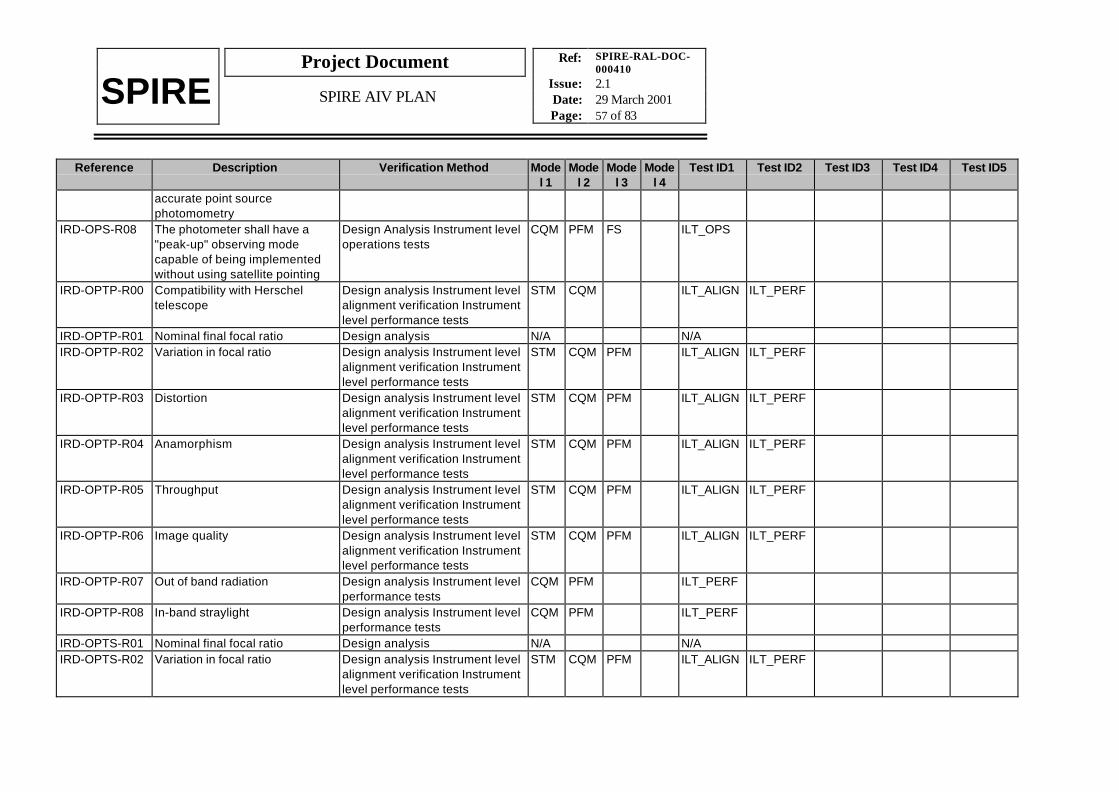
Ref: SPIRE-RAL-DOC-000410
Issue: 2.1Date: 29 March 2001Page: 57 of 83
Project Document
SPIRE SPIRE AIV PLAN
Reference Description Verification Method Model 1
Model 2
Model 3
Model 4
Test ID1 Test ID2 Test ID3 Test ID4 Test ID5
accurate point sourcephotomometry
IRD-OPS-R08 The photometer shall have a"peak-up" observing modecapable of being implementedwithout using satellite pointing
Design Analysis Instrument leveloperations tests
CQM PFM FS ILT_OPS
IRD-OPTP-R00 Compatibility with Herscheltelescope
Design analysis Instrument levelalignment verification Instrumentlevel performance tests
STM CQM ILT_ALIGN ILT_PERF
IRD-OPTP-R01 Nominal final focal ratio Design analysis N/A N/AIRD-OPTP-R02 Variation in focal ratio Design analysis Instrument level
alignment verification Instrumentlevel performance tests
STM CQM PFM ILT_ALIGN ILT_PERF
IRD-OPTP-R03 Distortion Design analysis Instrument levelalignment verification Instrumentlevel performance tests
STM CQM PFM ILT_ALIGN ILT_PERF
IRD-OPTP-R04 Anamorphism Design analysis Instrument levelalignment verification Instrumentlevel performance tests
STM CQM PFM ILT_ALIGN ILT_PERF
IRD-OPTP-R05 Throughput Design analysis Instrument levelalignment verification Instrumentlevel performance tests
STM CQM PFM ILT_ALIGN ILT_PERF
IRD-OPTP-R06 Image quality Design analysis Instrument levelalignment verification Instrumentlevel performance tests
STM CQM PFM ILT_ALIGN ILT_PERF
IRD-OPTP-R07 Out of band radiation Design analysis Instrument levelperformance tests
CQM PFM ILT_PERF
IRD-OPTP-R08 In-band straylight Design analysis Instrument levelperformance tests
CQM PFM ILT_PERF
IRD-OPTS-R01 Nominal final focal ratio Design analysis N/A N/AIRD-OPTS-R02 Variation in focal ratio Design analysis Instrument level
alignment verification Instrumentlevel performance tests
STM CQM PFM ILT_ALIGN ILT_PERF

Ref: SPIRE-RAL-DOC-000410
Issue: 2.1Date: 29 March 2001Page: 58 of 83
Project Document
SPIRE SPIRE AIV PLAN
Reference Description Verification Method Model 1
Model 2
Model 3
Model 4
Test ID1 Test ID2 Test ID3 Test ID4 Test ID5
IRD-OPTS-R03 Distortion Design analysis Instrument levelalignment verification Instrumentlevel performance tests
STM CQM PFM ILT_ALIGN ILT_PERF
IRD-OPTS-R04 Anamorphism Design analysis Instrument levelalignment verification Instrumentlevel performance tests
STM CQM PFM ILT_ALIGN ILT_PERF
IRD-OPTS-R05 Theoretical throughput Design analysis Instrument levelalignment verification Instrumentlevel performance tests
STM CQM PFM ILT_ALIGN ILT_PERF
IRD-OPTS-R06 Image quality Design analysis Instrument levelalignment verification Instrumentlevel performance tests
STM CQM PFM ILT_ALIGN ILT_PERF
IRD-OPTS-R07 Balancing of ports Design analysis Instrument levelperformance tests
CQM PFM ILT_PERF
IRD-OPTS-R08 Out of band radiation Design analysis Instrument levelperformance tests
CQM PFM ILT_PERF
IRD-OPTS-R09 In band straylight Design analysis Instrument levelperformance tests
CQM PFM ILT_PERF
IRD-OPTS-R10 Off axis resolution Design analysis Instrument levelperformance tests
CQM PFM ILT_PERF
IRD-PHOT-R01 Nominal passband Design analysis Instrument levelperformance test
CQM PFM ILT_PERF
IRD-PHOT-R02 Field of View Design analysis Instrument levelperformance test
CQM PFM ILT_PERF
IRD-PHOT-R03 Beam FWHM (Arcsec) Design analysis Instrument levelperformance test
CQM PFM ILT_PERF
IRD-PHOT-R04 Point source sensitivity Design analysis Instrument levelperformance test
CQM PFM ILT_PERF
IRD-PHOT-R05 Mapping sensitivity for one FOV Design analysis Instrument levelperformance test
CQM PFM ILT_PERF
IRD-PHOT-R06 Maximising 'mapping speed' atwhich confusion limit is reachedover a large area of sky is the
Design analysis N/A N/A

Ref: SPIRE-RAL-DOC-000410
Issue: 2.1Date: 29 March 2001Page: 59 of 83
Project Document
SPIRE SPIRE AIV PLAN
Reference Description Verification Method Model 1
Model 2
Model 3
Model 4
Test ID1 Test ID2 Test ID3 Test ID4 Test ID5
primary science driver. Thismeans maximising sensitivityand field-of-view (FOV) but NOTat the expense of spatialresolution.
IRD-PHOT-R10 Field distortion must be <10%across the FOV
Design analysis Instrument levelperformance test
CQM PFM ILT_PERF
IRD-PHOT-R11 Electrical crosstalk should be<1% (goal 0.5%) betweennearest-neighbour pixels and<0.1 % (gaol 0.05%) between allother pixels in the same array.
Design analysis Instrument levelwarm functional tests Instrumentlevel performance test
CQM PFM ILT_WFT ILT_PERF
IRD-PHOT-R12 NEP variation should be < 20%across each array.
Design analysis Instrument levelperformance tests
CQM PFM ILT_PERF
IRD-PHOT-R13 The photometer dynamic rangefor astronomical signals shall be> 12 bits.
Design analysis Instrument levelwarm functional tests
CQM ILT_WFT
IRD-PHOT-R14 Absolute photometric accuracyshould be <15% at allwavelengths with a goal of <10%
Design analysis Instrument levelcalibration
PFM ILT_CAL
IRD-PHOT-R15 The relative photometric accuracyshall be <10% with a gaol of <5%
Design analysis Instrument levelcalibration
PFM ILT_CAL
IRD-PHOT-R16 The three arrays need to be co-aligned to within 1 arcsecond.
Design analysis Instrumentalignment verification Instrumentlevel performance tests
CQM PFM ILT_ALIGN ILT_PERF
IRD-PHOT-R17 The maximum available chopthrow shall be at least 4arcminutes; the minimum shallbe 10 arcsecs or less
Design analysis Instrument levelperformance tests
CQM PFM ILT_PERF
IRD-PHOT-R18 SPIRE Photometricmeasurements shall be linear to5% over a dynamic range of 4000for astronomical signals
Design analysis Instrument levelperformance tests
CQM PFM ILT_PERF

Ref: SPIRE-RAL-DOC-000410
Issue: 2.1Date: 29 March 2001Page: 60 of 83
Project Document
SPIRE SPIRE AIV PLAN
Reference Description Verification Method Model 1
Model 2
Model 3
Model 4
Test ID1 Test ID2 Test ID3 Test ID4 Test ID5
IRD-REL-R01 As far as possible the total failureof a single sub-system shall notlead to the total loss ofinstrument operations.
Design analysis (FMECA) N/A N/A
IRD-REL-R02 Backup modes of operationshould be available for allnominal observing modes.These shall be designed to allowthe continued use of that modealbeit with degradedperformance or efficiency.
Design analysis Instrument levelwarm functional tests Instrumentlevel cold functional testsInstrument level operations tests
CQM PFM ILT_WFT ILT_CFT ILT_OPS
IRD-REL-R03 Cold redundant hardware shallbe provided wherever practicablewithin the instrument design.
Design analysis N/A N/A
IRD-REL-R04 As far as possible all controlloops shall be implementedthrough the use of on-boardsoftware.
Design analysis N/A N/A
IRD-REL-R05 It shall be possible to break allcontrol loops implemented inhardware.
Design analysis N/A N/A
IRD-RFM-R01 RF rejection Design analysis Instrument levelEMC tests
CQM PFM ILT_EMC
IRD-RFM-R02 Envelope Design analysis Instrument levelintegration verification Subsystemacceptance data package
STM CQM PFM ILT_INTG
IRD-RFM-R03 Dissipation Design analysis Instrument levelcold functional test
CQM PFM ILT_CFT
IRD-RFM-R04 Operating temperature range Design analysis Instrument levelperformance test
CQM PFM ILT_PERF
IRD-RFM-R05 Nominal operating temperature Design analysis Instrument levelcold functional test
CQM PFM ILT_CFT
IRD-RFM-R06 Mechanical interface Design analysis N/A N/A

Ref: SPIRE-RAL-DOC-000410
Issue: 2.1Date: 29 March 2001Page: 61 of 83
Project Document
SPIRE SPIRE AIV PLAN
Reference Description Verification Method Model 1
Model 2
Model 3
Model 4
Test ID1 Test ID2 Test ID3 Test ID4 Test ID5
IRD-RFM-R07 First natural frequency Design analysis Subsystemverification programmeSubsystem acceptance datapackage
N/A N/A
IRD-SAFE-R01 During all mission phases thereshall be no requirement forcommands to be sent from theground to the instrument with animmediate response time (i.e.less than 2 minutes TBC).
Design analysis N/A N/A
IRD-SAFE-R02 Situations which requireresponse from the ground withina short time (i.e. less than 30mins) shall be reduced to aminimum be well identified andagreed by ESA
Design analysis N/A N/A
IRD-SAFE-R03 Situations which requireresponse from the ground withina short time (i.e. less than 30mins) shall be unambiguouslyrecognisable in the instrumenthousekeeping telemetry withoutcomplex processing
Design analysis N/A N/A
IRD-SAFE-R04 Housekeeping telemetry shall begenerated during all nominalmodes of the instrument.
Design analysis AVM functionaltests Instrument level operationstests
AVM CQM PFM FS AVM_FUNC
ILT_OPS
IRD-SAFE-R05 The instrument shall be able toaccept all telecommand packetssent to it at the nominal transferrate from the CDMS
Design analysis AVM functionaltests
AVM AVM_FUNC
IRD-SAFE-R06 It shall not be possible bycommand or lack of command toplace the instrument into a
Design analysis AVM functionaltests?
AVM AVM_FUNC

Ref: SPIRE-RAL-DOC-000410
Issue: 2.1Date: 29 March 2001Page: 62 of 83
Project Document
SPIRE SPIRE AIV PLAN
Reference Description Verification Method Model 1
Model 2
Model 3
Model 4
Test ID1 Test ID2 Test ID3 Test ID4 Test ID5
configuration that will or is likelyto cause damage to anysubsystem
IRD-SAFE-R07 All telecommands received bythe instrument shall be checkedto be correctly formatted andcomplete before execution.Incorrect telecommands will berejected by the instrument
Design analysis AVM functionaltests
AVM AVM_FUNC
IRD-SAFE-R08 Failure of any sub-system or oneof its components shall not affectthe health of any othersubsystem the instrument or theinterface with the satellite.
Design analysis (FMECA) N/A N/A
IRD-SAFE-R09 Failure of any component in asubsystem shall not damage anyredundant or backup componentdesigned to replace thatcomponent in the subsystem
Design analysis (FMECA) N/A N/A
IRD-SAFE-R10 No electronics sub-unit shall becapable of affecting instrumentoperations until it is in a definedstate. This state shall beconfirmed in the housekeepingtelemetry.
Design analysis AVM functionaltests
AVM AVM_FUNC
IRD-SAFE-R11 No commands shall be sent toan electronics sub-unit until theyare in a defined state confirmedby the on-board software
Design analysis AVM functionaltests
AVM AVM_FUNC
IRD-SHUT-R01 Beam blanking Design analysis Instrument levelperformance test
CQM PFM ILT_PERF
IRD-SHUT-R02 Vane emission Design analysis Instrument levelperformance test
CQM PFM ILT_PERF

Ref: SPIRE-RAL-DOC-000410
Issue: 2.1Date: 29 March 2001Page: 63 of 83
Project Document
SPIRE SPIRE AIV PLAN
Reference Description Verification Method Model 1
Model 2
Model 3
Model 4
Test ID1 Test ID2 Test ID3 Test ID4 Test ID5
IRD-SHUT-R03 Vane states Design analysis Instrument levelwarm functional test Instrumentcold functional test
CQM PFM ILT_WFT ILT_CFT
IRD-SHUT-R04 Failure mode Design analysis (FMECA)Instrument level warm functionaltest Instrument level coldfunctional test
CQM PFM ILT_WFT ILT_CFT
IRD-SHUT-R05 Operating temperature Design analysis Instrument levelwarm functional test Instrumentlevel cold functional test
CQM PFM ILT_WFT ILT_CFT
IRD-SHUT-R06 Operating Orientation Design analysis Instrument levelwarm functional test Instrumentlevel cold functional test
CQM PFM ILT_WFT ILT_CFT
IRD-SHUT-R07 Actuator envelope Design analysis Instrument levelintegration verification Subsystemacceptance data package
STM CQM ILT_INTG
IRD-SHUT-R08 Eigenfrequency Design analysis Subsystemverification programmeSubsystem acceptance datapackage
N/A N/A
IRD-SHUT-R09 Materials Design analysis Subsystemacceptance data package
N/A N/A
IRD-SHUT-R10 Transition time Design analysis Instrument levelcold functional test
CQM PFM ILT_CFT
IRD-SHUT-R11 Thermal stabilisation time Design analysis Instrument levelperformance tests
CQM PFM ILT_PERF
IRD-SHUT-R12 Thermometry Design analysis N/A N/AIRD-SHUT-R13 Thermal dissipation Design analysis Instrument level
thermal verificationCQM ILT_THER
IRD-SHUT-R14 Cryoharness thermal dissipation Design analysis Instrument levelthermal verification
CQM ILT_THER
IRD-SMEC-R01 Linear Travel Design analysis Instrument levelcold functional test Instrument
CQM PFM ILT_CFT ILT_PERF

Ref: SPIRE-RAL-DOC-000410
Issue: 2.1Date: 29 March 2001Page: 64 of 83
Project Document
SPIRE SPIRE AIV PLAN
Reference Description Verification Method Model 1
Model 2
Model 3
Model 4
Test ID1 Test ID2 Test ID3 Test ID4 Test ID5
level performance testIRD-SMEC-R02 Minimum movement sampling
intervalDesign analysis Instrument levelcold functional test Instrumentlevel performance test
CQM PFM ILT_CFT ILT_PERF
IRD-SMEC-R03 Sampling step control Design analysis Instrument levelcold functional test Instrumentlevel performance test
CQM PFM ILT_CFT ILT_PERF
IRD-SMEC-R04 Scan length Design analysis Instrument levelcold functional test Instrumentlevel operations tests
CQM PFM ILT_CFT ILT_OPS
IRD-SMEC-R05 Dead-time Design analysis Instrument levelcold functional test Instrumentlevel performance test
CQM PFM ILT_CFT ILT_PERF
IRD-SMEC-R06 Mirror velocity Design analysis Instrument levelcold functional test Instrumentlevel performance test
CQM PFM ILT_CFT ILT_PERF
IRD-SMEC-R07 Velocity control Design analysis Instrument levelcold functional test Instrumentlevel performance test
CQM PFM ILT_CFT ILT_PERF
IRD-SMEC-R08 Velocity stability Design analysis Instrument levelcold functional test Instrumentlevel performance test
CQM PFM ILT_CFT ILT_PERF
IRD-SMEC-R09 Position measurement Design analysis Instrument levelcold functional test Instrumentlevel performance test
CQM PFM ILT_CFT ILT_PERF
IRD-SMEC-R10 Sampling frequency Design analysis Instrument levelcold functional test Instrumentlevel performance test
CQM PFM ILT_CFT ILT_PERF
IRD-SMEC-R11 Maximum thermal load onto level1 during cold operation -mechanism and cold positionmeasurement system.
Design analysis Instrument levelthermal verification Instrumentlevel cold functional testInstrument level operations tests
STM CQM PFM ILT_THER ILT_OPS
IRD-SMEC-R12 Maximum envelope Design analysis Instrument level STM CQM ILT_INTG

Ref: SPIRE-RAL-DOC-000410
Issue: 2.1Date: 29 March 2001Page: 65 of 83
Project Document
SPIRE SPIRE AIV PLAN
Reference Description Verification Method Model 1
Model 2
Model 3
Model 4
Test ID1 Test ID2 Test ID3 Test ID4 Test ID5
integration verification Subsystemacceptance data package
IRD-SMEC-R13 Thermometers Design Analysis N/A N/AIRD-SMEC-R14 Ground Operation Design analysis Instrument level
cold functional testsCQM PFM ILT_CFT
IRD-SPEC-R01 Wavelength range Design analysis Instrument levelperformance tests
CQM PFM ILT_PERF
IRD-SPEC-R02 Maximum Resolution Design Analysis Instrument levelperformance test
CQM PFM ILT_PERF
IRD-SPEC-R03 Minimum Resolution Design Analysis Instrument levelperformance test
CQM PFM ILT_PERF
IRD-SPEC-R04 Field of View (Arcmin) Design analysis Instrument levelperformance tests
CQM PFM ILT_PERF
IRD-SPEC-R05 Beam FWHM (Arcsec) Design analysis Instrument levelperformance test
CQM PFM ILT_PERF
IRD-SPEC-R06 Point source continuumsensitivity Point sourceunresolved line sensitivity
Design analysis Instrument levelperformance test
CQM PFM ILT_PERF
IRD-SPEC-R07 Map continuum sensitivity Mapline sensitivity
Design analysis Instrument levelperformance test
CQM PFM ILT_PERF
IRD-SPEC-R08 The spectrometer design shallbe optimised for sensitivity topoint sources
Design analysis N/A N/A
IRD-SPEC-R11 The width of the FTS instrumentresponse function shall beuniform to within 10% across theFOV for resolution <0.4 cm-1
Design analysis Instrument levelperformance test
CQM PFM ILT_PERF
IRD-SPEC-R14 Fringe contrast shall be greaterthan 80% for any point in the fieldof view for a resolution of 0.4 cm-1.
Design analysis Instrument levelperformance test
CQM PFM ILT_PERF
IRD-SPEC-R15 The spectrometer dynamic rangefor astronomical signals shall be
Design analysis Instrument levelwarm functional tests
CQM ILT_WFT

Ref: SPIRE-RAL-DOC-000410
Issue: 2.1Date: 29 March 2001Page: 66 of 83
Project Document
SPIRE SPIRE AIV PLAN
Reference Description Verification Method Model 1
Model 2
Model 3
Model 4
Test ID1 Test ID2 Test ID3 Test ID4 Test ID5
12 bits or higherIRD-SPEC-R16 The FTS absolute photometric
accuracy at the requiredresolution shall <15% at allwavelengths with a goal of <10%
Design analysis Instrument levelcalibration
PFM ILT_CAL
IRD-SPEC-R17 The sensitivity of the FTS at anyspectral resolution up to the goalvalue shall be limited by thephoton noise from the Herscheltelescope within the chosenpassband
Design analysis Instrument levelperformance tests
CQM PFM ILT_CAL
IRD-STRC-R01 Alignment of the instrument w.r.t.the Herschel optical axis
Design analysis Instrumentalignment verification
STM CQM PFM ILT_ALIGN
IRD-STRC-R02 Attenuation of RF by CommonStructure covers
Design analysis Instrument levelEMC tests
STM ILT_EMC
IRD-STRC-R03 Items requiring support from theCommon Structure
Design analysis N/A N/A
IRD-STRC-R04 Optics and associated sub-system alignment
Design analysis Instrumentalignment verification
STM CQM PFM ILT_ALIGN
IRD-STRC-R05 Surface finish of the CommonStructure cover
Design analysis Instrument levelthermal verification
STM ILT_THER
IRD-STRC-R06 Pumping port Design analysis Instrument levelintegration verification
STM ILT_INTG
IRD-STRC-R07 Thermometry Design analysis N/A N/AIRD-STRC-R08 Attenuation of radiation from
cryostat environmentDesign analysis Instrument levelperformance tests
CQM ILT_PERF
IRD-STRC-R09 First natural frequency of theinstrument assembly
Design analysis Instrument levelvibration tests
STM PFM ILT_VIB
IRD-STRC-R10 Instrument mechanical interface Design analysis N/A N/AIRD-STRC-R12 Grounding Design analysis Instrument level
integration verificationSTM CQM PFM ILT_INTG
IRD-STRC-R13 Electrical isolation from Herschel Design analysis Instrument levelintegration verification
STM CQM PFM ILT_INTG
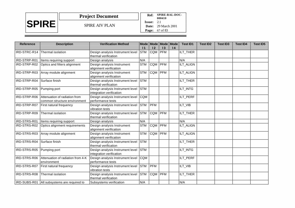
Ref: SPIRE-RAL-DOC-000410
Issue: 2.1Date: 29 March 2001Page: 67 of 83
Project Document
SPIRE SPIRE AIV PLAN
Reference Description Verification Method Model 1
Model 2
Model 3
Model 4
Test ID1 Test ID2 Test ID3 Test ID4 Test ID5
IRD-STRC-R14 Thermal isolation Design analysis Instrument levelthermal verification
STM CQM PFM ILT_THER
IRD-STRP-R01 Items requiring support Design analysis N/A N/AIRD-STRP-R02 Optics and filters alignment Design analysis Instrument
alignment verificationSTM CQM PFM ILT_ALIGN
IRD-STRP-R03 Array module alignment Design analysis Instrumentalignment verification
STM CQM PFM ILT_ALIGN
IRD-STRP-R04 Surface finish Design analysis Instrument levelthermal verification
STM ILT_THER
IRD-STRP-R05 Pumping port Design analysis Instrument levelintegration verification
STM ILT_INTG
IRD-STRP-R06 Attenuation of radiation fromcommon structure environment
Design analysis Instrument levelperformance tests
CQM ILT_PERF
IRD-STRP-R07 First natural frequency Design analysis Instrument levelvibration tests
STM PFM ILT_VIB
IRD-STRP-R09 Thermal isolation Design analysis Instrument levelthermal verification
STM CQM PFM ILT_THER
IRD-STRS-R01 Items requiring support Design analysis N/A N/AIRD-STRS-R02 Optics alignment requirements Design analysis Instrument
alignment verificationSTM CQM PFM ILT_ALIGN
IRD-STRS-R03 Array module alignment Design analysis Instrumentalignment verification
STM CQM PFM ILT_ALIGN
IRD-STRS-R04 Surface finish Design analysis Instrument levelthermal verification
STM ILT_THER
IRD-STRS-R05 Pumping port Design analysis Instrument levelintegration verification
STM ILT_INTG
IRD-STRS-R06 Attenuation of radiation from 4-Kenvironment
Design analysis Instrument levelperformance tests
CQM ILT_PERF
IRD-STRS-R07 First natural frequency Design analysis Instrument levelvibration tests
STM PFM ILT_VIB
IRD-STRS-R08 Thermal isolation Design analysis Instrument levelthermal verification
STM CQM PFM ILT_THER
IRD-SUBS-R01 All subsystems are required to Subsystems verification N/A N/A

Ref: SPIRE-RAL-DOC-000410
Issue: 2.1Date: 29 March 2001Page: 68 of 83
Project Document
SPIRE SPIRE AIV PLAN
Reference Description Verification Method Model 1
Model 2
Model 3
Model 4
Test ID1 Test ID2 Test ID3 Test ID4 Test ID5
undergo an environmental testprogramme that demonstratesthe design and build standard ofthe sub-system models will becompatible with theenvironmental test programme tobe carried out on the appropriateintegrated instrument model.
programme
IRD-SUBS-R02 All sub-systems are required todemonstrate that they willoperate successfully over the4.25 years of expected missionoperations following launch.
Subsystems verificationprogramme
N/A N/A
IRD-SUBS-R03 All subsystems are required tobe within the mass allocationgiven in RD8
Subsystems acceptance datapackage
N/A N/A
IRD-TLM-R01 The instrument shall be capableof transferring telemetry packetsto the CDMS (or simulator) at upto the maximum rate allowed bythe telemetry interface.
Design analysis AVM functionaltests
AVM AVM_FUNC
IRD-TLM-R02 The instrument shall be able tobuffer telemetry packets until theyare requested by the CDMS
Design analysis AVM functionaltests
AVM AVM_FUNC
IRD-TLM-R03 It shall be possible to validate thecontent of each telemetry packet.
Design analysis AVM functionaltests
AVM AVM_FUNC
IRD-TLM-R04 All telemetry packets shallcontain information identifyingthe observation/step beingexecuted.
Design analysis AVM functionaltests
AVM AVM_FUNC
IRD-TLM-R05 The instrument shall generatehousekeeping data packets in alloperating modes.
Design analysis AVM functionaltests
AVM AVM_FUNC

Ref: SPIRE-RAL-DOC-000410
Issue: 2.1Date: 29 March 2001Page: 69 of 83
Project Document
SPIRE SPIRE AIV PLAN
Reference Description Verification Method Model 1
Model 2
Model 3
Model 4
Test ID1 Test ID2 Test ID3 Test ID4 Test ID5
IRD-TLM-R06 It shall be possible to define TBCalternative housekeeping packetstructures with different rates ofgeneration.
Design analysis AVM functionaltests
AVM AVM_FUNC
IRD-TLM-R07 The instrument shall generatescience data packets in allobserving modes.
Design analysis AVM functionaltests
AVM AVM_FUNC
IRD-TLM-R07 It shall be possible to define TBCalternative science data packetsstructures.
Design analysis AVM functionaltests
AVM AVM_FUNC
IRD-TLM-R08 The instrument shall generateevent packets in all operatingmodes.
Design analysis AVM functionaltests Instrument level operationstests
AVM CQM PFM FS AVM_FUNC
ILT_OPS
IRD-VER-01 The STM verification testing shalldemonstrate that the proposedstructure design is capable ofmeeting the mechanicalenvironmental conditionsspecified for the Herschellaunch. The STM vibration shallbe used to verify the stiffness andstrength of the structure andverify the mechanical andthermal transfer functionsbetween the various parts of thecold focal plane units and theHerschel satellite.
Instrument level vibration testsInstrument level thermalverificationtests
STM ILT_VIB ILT_THER
IRD-VER-R02 The AVM verification testing shalldemonstrate that the instrumentwill fulfil the requirements on thefollowing: Communicationbetween the satellite CDMS andthe DPU. Correct transfer andreceipt of instrument commands
AVM functional tests AVM AVM_FUNC

Ref: SPIRE-RAL-DOC-000410
Issue: 2.1Date: 29 March 2001Page: 70 of 83
Project Document
SPIRE SPIRE AIV PLAN
Reference Description Verification Method Model 1
Model 2
Model 3
Model 4
Test ID1 Test ID2 Test ID3 Test ID4 Test ID5
from the satellite Correct transferand receipt of instrument datapackets form the instrument tothe satellite Correct execution ofinstrument commands Correcttransfer of instrument data fromthe FPU simulator to the DPUCorrect execution of DPU on-board software for any datacompression algorithms andpacket generation for allinstrument data packet types.
IRD-VER-R03 The CQM verification testing shalldemonstrate that the followingconditions are met or are likely tobe met on the PFM: Correctoperation of all FPU sub-systems at cryogenictemperatures for all instrumentoperation modes for both primeand redundant systems. Theinstrument cold FPU and JFETbox thermal dissipation is withinrequirements for all instrumentoperation modes. The warmelectronics thermal dissipation atroom temperature is withinrequirements. Correct operationof all on-board software. Theinstrument straylight environmentis within requirements Theinstrument optics performance iswithin requirements Theperformance of the instrument
Instrument level warm functionaltests Instrument level coldfunctional tests Instrument levelperformance tests
CQM ILT_WFT ILT_CFT ILT_PERF

Ref: SPIRE-RAL-DOC-000410
Issue: 2.1Date: 29 March 2001Page: 71 of 83
Project Document
SPIRE SPIRE AIV PLAN
Reference Description Verification Method Model 1
Model 2
Model 3
Model 4
Test ID1 Test ID2 Test ID3 Test ID4 Test ID5
meets the scientificrequirements expected for theCQM for all instrument observingmodes Development and test ofall functional test sequencesrequired for Integrated SystemsTesting (IST) at satellite level.The correct functioning of theinstrument for all observingmodes and calibrationsequences. Development andtest of all in-flight functional andperformance test sequences
IRD-VER-R04 The PFM verification testing shallin addition to the requirementson the CQM and AVM verificationdemonstrate the following: Theperformance of the flightinstrument meets the scientificrequirements for all instrumentobserving modes. Correctoperation of flight version of allon-board software. Thecharacterisation of the PFMinstrument performance for allinstrument observing modes -including generation of data forinstrument calibration andfunctional testing both during ISTand in-flight. The characterisationof the instrument performancewith the warm electronicsoperating over a range oftemperatures Final test of all
Instrument level warm functionaltests Instrument level coldfunctional tests Instrument levelperformance tests Instrumentlevel operations tests Instrumentlevel calibration
PFM FS ILT_WFT ILT_CFT ILT_PERF ILT_OPS ILT_CAL

Ref: SPIRE-RAL-DOC-000410
Issue: 2.1Date: 29 March 2001Page: 72 of 83
Project Document
SPIRE SPIRE AIV PLAN
Reference Description Verification Method Model 1
Model 2
Model 3
Model 4
Test ID1 Test ID2 Test ID3 Test ID4 Test ID5
functional test sequences for IST.Final test of all observing modesFinal test of all in-flight functionaland performance testsequences.
IRD-WE-R01 Packet Services Design analysis AVM functionaltests Warm electronicsaccptance tests Instrument levelwarm functional tests
AVM CQM PFM AVM_FUNC
ILT_WFT
IRD-WE-R02 Telecommands Design analysis AVM functionaltests Instrument level warmfunctional tests
AVM CQM PFM AVM_FUNC
ILT_WFT
IRD-WE-R03 Telemetry Design analysis AVM functionaltests Instrument level warmfunctional tests
AVM CQM PFM AVM_FUNC
ILT_WFT
IRD-WE-R04 Housekeeping Design analysis AVM functionaltests Instrument level warmfunctional tests
AVM CQM PFM AVM_FUNC
ILT_WFT
IRD-WE-R05 Operating Modes Design analysis AVM functionaltests Instrument level warmfunctional tests Instrument leveloperations tests
AVM CQM PFM AVM_FUNC
ILT_WFT ILT_OPS
IRD-WE-R06 Command Services Design analysis AVM functionaltests Instrument level warmfunctional tests
AVM CQM PFM AVM_FUNC
ILT_WFT
IRD-WE-R07 Data Handling Design analysis AVM functionaltests Instrument level warmfunctional tests Instrument leveloperations tests
AVM CQM PFM AVM_FUNC
ILT_WFT ILT_OPS
IRD-WE-R08 Photometer detector readout Design analysis AVM functionaltest Instrument level coldfunctional tests Instrumentperformance tests
AVM CQM PFM AVM_FUNC
ILT_CFT ILT_PERF
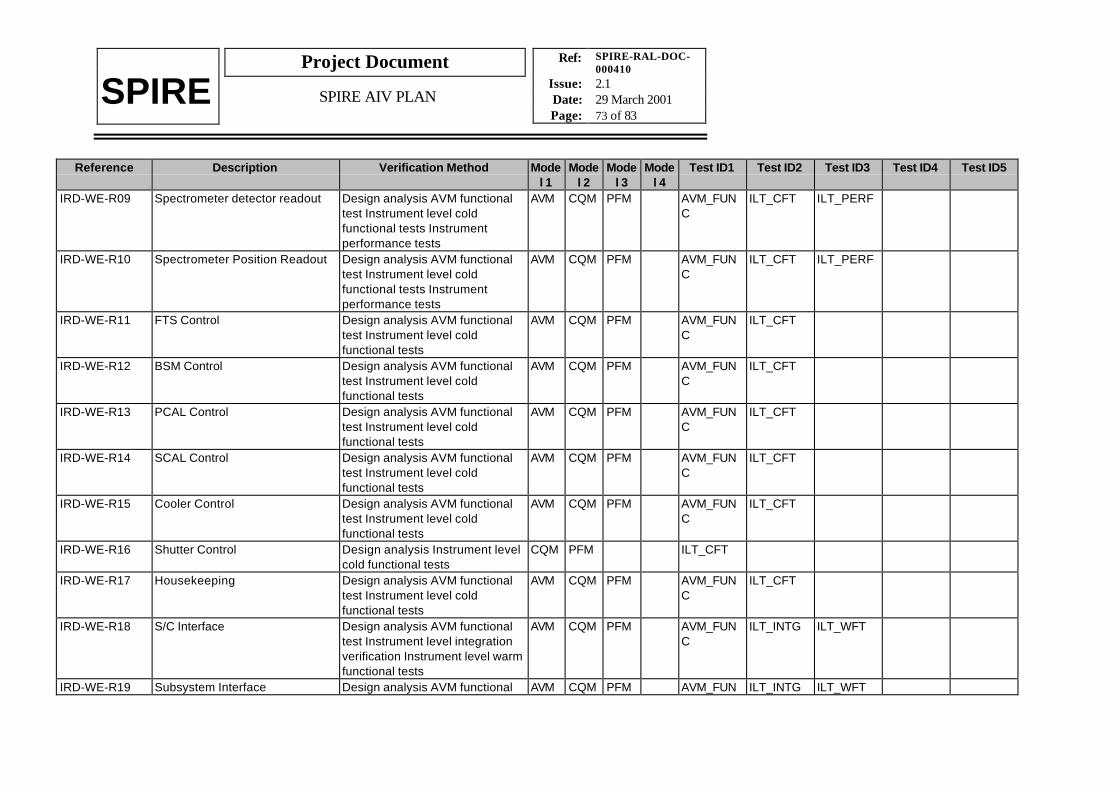
Ref: SPIRE-RAL-DOC-000410
Issue: 2.1Date: 29 March 2001Page: 73 of 83
Project Document
SPIRE SPIRE AIV PLAN
Reference Description Verification Method Model 1
Model 2
Model 3
Model 4
Test ID1 Test ID2 Test ID3 Test ID4 Test ID5
IRD-WE-R09 Spectrometer detector readout Design analysis AVM functionaltest Instrument level coldfunctional tests Instrumentperformance tests
AVM CQM PFM AVM_FUNC
ILT_CFT ILT_PERF
IRD-WE-R10 Spectrometer Position Readout Design analysis AVM functionaltest Instrument level coldfunctional tests Instrumentperformance tests
AVM CQM PFM AVM_FUNC
ILT_CFT ILT_PERF
IRD-WE-R11 FTS Control Design analysis AVM functionaltest Instrument level coldfunctional tests
AVM CQM PFM AVM_FUNC
ILT_CFT
IRD-WE-R12 BSM Control Design analysis AVM functionaltest Instrument level coldfunctional tests
AVM CQM PFM AVM_FUNC
ILT_CFT
IRD-WE-R13 PCAL Control Design analysis AVM functionaltest Instrument level coldfunctional tests
AVM CQM PFM AVM_FUNC
ILT_CFT
IRD-WE-R14 SCAL Control Design analysis AVM functionaltest Instrument level coldfunctional tests
AVM CQM PFM AVM_FUNC
ILT_CFT
IRD-WE-R15 Cooler Control Design analysis AVM functionaltest Instrument level coldfunctional tests
AVM CQM PFM AVM_FUNC
ILT_CFT
IRD-WE-R16 Shutter Control Design analysis Instrument levelcold functional tests
CQM PFM ILT_CFT
IRD-WE-R17 Housekeeping Design analysis AVM functionaltest Instrument level coldfunctional tests
AVM CQM PFM AVM_FUNC
ILT_CFT
IRD-WE-R18 S/C Interface Design analysis AVM functionaltest Instrument level integrationverification Instrument level warmfunctional tests
AVM CQM PFM AVM_FUNC
ILT_INTG ILT_WFT
IRD-WE-R19 Subsystem Interface Design analysis AVM functional AVM CQM PFM AVM_FUN ILT_INTG ILT_WFT

Ref: SPIRE-RAL-DOC-000410
Issue: 2.1Date: 29 March 2001Page: 74 of 83
Project Document
SPIRE SPIRE AIV PLAN
Reference Description Verification Method Model 1
Model 2
Model 3
Model 4
Test ID1 Test ID2 Test ID3 Test ID4 Test ID5
test Instrument level integrationverification Instrument level warmfunctional tests
C
IRD-WE-R20 Subsystem Control Loops Design analysis AVM Functionaltest Instrument level warmfunctional test Instrument levelcold functional test
AVM CQM PFM AVM_FUNC
ILT_WFT ILT_CFT
IRD-WE-R21 Subsystem Data Acquisition Design analysis AVM Functionaltest Instrument level warmfunctional test Instrument levelcold functional test Instrumentlevel operations tests
AVM CQM PFM AVM_FUNC
ILT_WFT ILT_CFT ILT_OPS
IRD-WE-R22 Data Processing Design analysis AVM Functionaltest Instrument level warmfunctional test Instrument levelcold functional test Instrumentlevel operations tests
AVM CQM PFM AVM_FUNC
ILT_WFT ILT_CFT ILT_OPS
IRD-WE-R23 Communication Design analysis AVM Functionaltest Instrument level warmfunctional test Instrument levelcold functional test Instrumentlevel operations tests
AVM CQM PFM AVM_FUNC
ILT_WFT ILT_CFT ILT_OPS
IRD-WE-R24 WE anomalies Design analysis AVM Functionaltest Instrument level warmfunctional test Instrument levelcold functional test Instrumentlevel operations tests
AVM CQM PFM AVM_FUNC
ILT_WFT ILT_CFT ILT_OPS
IRD-WE-R25 Subsystem anomalies Design analysis AVM Functionaltest Instrument level warmfunctional test Instrument levelcold functional test Instrumentlevel operations tests
AVM CQM PFM AVM_FUNC
ILT_WFT ILT_CFT ILT_OPS
IRD-WE-R26 Anomaly Management Design analysis AVM Functional AVM CQM PFM AVM_FUN ILT_WFT ILT_CFT ILT_OPS

Ref: SPIRE-RAL-DOC-000410
Issue: 2.1Date: 29 March 2001Page: 75 of 83
Project Document
SPIRE SPIRE AIV PLAN
Reference Description Verification Method Model 1
Model 2
Model 3
Model 4
Test ID1 Test ID2 Test ID3 Test ID4 Test ID5
test Instrument level warmfunctional test Instrument levelcold functional test Instrumentlevel operations tests
C
IRD-WE-R27 Failure resiliance Design analysis (FMECA) N/A N/AIRD-WE-R28 Lifetime Design analysis N/A N/AIRD-WE-R29 External Stress Design analysis (FMECA) N/A N/AIRD-WE-R30 S/C Safety Design analysis (FMECA) N/A N/AIRD-WE-R31 Instrument Safety Design analysis (FMECA) N/A N/AIRD-WE-R32 Failure Propagation Design analysis (FMECA) N/A N/AIRD-WE-R33 Mass Design analysis Subsystem
acceptance data packageN/A N/A
IRD-WE-R34 Volume Design analysis Subsystemacceptance data package
N/A N/A
IRD-WE-R35 Power Design analysis AVM Functionaltest Instrument level warmfunctional test Instrument levelcold functional test Instrumentlevel operations tests
AVM CQM PFM AVM_FUNC
ILT_WFT ILT_CFT ILT_OPS
IRD-WE-R36 EMC Design analysis Instrument levelEMC tests
CQM PFM ILT_EMC
IRD-WE-R37 Quality Plan Design analysis Subsystemacceptance data package
N/A N/A
VRD-01 Mechanical frequency response Design analysis Instrument levelvibration tests Subsystemverification programme
STM ILT_VIB
VRD-02 Ability to withstand launchenvironment
Design analysis Instrument levelvibration tests Subsystemverification programme
STM ILT_VIB
VRD-03 Mechanical interface withHerschel system
Design analysis Instrument levelintegration verification
STM CQM ILT_INTG
VRD-04 Instrument level integration Design analysis Instrument levelacceptance data package
STM AVM CQM AVM_FUNC
ILT_INTG ILT_WFT

Ref: SPIRE-RAL-DOC-000410
Issue: 2.1Date: 29 March 2001Page: 76 of 83
Project Document
SPIRE SPIRE AIV PLAN
Reference Description Verification Method Model 1
Model 2
Model 3
Model 4
Test ID1 Test ID2 Test ID3 Test ID4 Test ID5
Instrument level integrationverification AVM functional testInstrument level warm functionaltest
VRD-05 Sub-system mechanicalinterfaces
Design analysis Subsystemacceptance data packageInstrument level integrationverification
STM CQM ILT_INTG
VRD-06 Optical design Design analysis Instrument levelalignment verification Instrumentlevel performance tests
STM CQM ILT_ALIGN ILT_PERF
VRD-07 Optical interface to Herschelsystem
Design analysis Instrument levelacceptance data packageInstrument level alignmentverification Instrument levelperformance tests
STM CQM ILT_ALIGN ILT_PERF
VRD-08 Straylight Design analysis Instrument levelalignment verification Instrumentlevel performance tests
CQM ILT_ALIGN ILT_PERF
VRD-09 Instrument optical performance Design analysis Instrument levelalignment verification Instrumentlevel performance tests
CQM ILT_ALIGN ILT_PERF
VRD-10 Integration and alignment Design analysis Instrument levelacceptance data packageInstrument level integrationverification Instrument levelalignment verification
STM CQM ILT_INTG ILT_ALIGN
VRD-11 Sub-system optical interfaces Design analysis Subsystemacceptance data packageInstrument level alignmentverification Instrument levelperformance verification
STM CQM ILT_ALIGN ILT_PERF
VRD-12 Thermal performance Design analysis Subsystem STM CQM ILT_THER ILT_CFT ILT_PERF

Ref: SPIRE-RAL-DOC-000410
Issue: 2.1Date: 29 March 2001Page: 77 of 83
Project Document
SPIRE SPIRE AIV PLAN
Reference Description Verification Method Model 1
Model 2
Model 3
Model 4
Test ID1 Test ID2 Test ID3 Test ID4 Test ID5
verification programmeSubsystem acceptance datapackage Instrument level thermalverification Instrument level coldfunctional test Instrument levelperformance tests
VRD-13 Thermal interface to Herschelsystem
Design analysis Instrument levelacceptance data packageInstrument level thermalverification
STM CQM ILT_THER
VRD-14 Sub-system thermal interfaces Design analysis Subsystemverification programmeSubsystem acceptance datapackage Instrument level thermalverification
STM CQM ILT_THER
VRD-15 Micro-vibration environment Subsystem verificationprogramme Subsystemacceptance data packageInstrument level performancetests
CQM ILT_PERF
VRD-16 Mechanism control Design analysis Subsystemverification programmeSubsystem acceptance datapackage AVM functional testInstrument level cold functionaltests Instrument levelperformance tests
AVM CQM AVM_FUNC
ILT_CFT ILT_PERF
VRD-17 Harness mechanical frequencyresponse and routing
Design analysis Instrument levelacceptance data packageInstrument level integrationverification Instrument level coldfunctional tests Instrument levelperformance tests
STM CQM ILT_INTG ILT_CFT ILT_PERF

Ref: SPIRE-RAL-DOC-000410
Issue: 2.1Date: 29 March 2001Page: 78 of 83
Project Document
SPIRE SPIRE AIV PLAN
Reference Description Verification Method Model 1
Model 2
Model 3
Model 4
Test ID1 Test ID2 Test ID3 Test ID4 Test ID5
VRD-18 Detector performance versusenvironment
Design analysis Subsystemverification programmeSubsystem acceptance datapackage Instrument levelperformance tests
CQM ILT_PERF
VRD-19 JFET Amplifier performanceversus environment
Design analysis Subsystemverification programmeSubsystem acceptance datapackage Instrument levelperformance tests
CQM ILT_PERF
VRD-20 Detector Harness performance Design analysis Subsystemverification programmeSubsystem acceptance datapackage Instrument levelperformance tests
CQM ILT_PERF
VRD-21 Detector sub-system interfacecompatibility - thermal electricalmechanical
Design analysis Subsystemacceptance data packageInstrument level integrationverification AVM functional testInstrument level warm functionaltests Instrument level coldfunctional tests
STM AVM CQM ILT_INTG AVM_FUNC
ILT_WFT ILT_CFT
VRD-22 End-to-end system performance Design analysis Instrument levelperformance tests
CQM ILT_PERF
VRD-23 EMC susceptibility and emissionradiated/conducted
Design analysis Subsystemverification programmeSubsystem acceptance datapackage Instrument level EMCtests
CQM ILT_EMC
VRD-24 Electrical grounding Design analysis Instrument levelwarm functional tests Instrumentlevel cold functional testsInstrument level performance
CQM ILT_WFT ILT_CFT ILT_PERF

Ref: SPIRE-RAL-DOC-000410
Issue: 2.1Date: 29 March 2001Page: 79 of 83
Project Document
SPIRE SPIRE AIV PLAN
Reference Description Verification Method Model 1
Model 2
Model 3
Model 4
Test ID1 Test ID2 Test ID3 Test ID4 Test ID5
testsVRD-25 Faraday cage integrity and
performanceDesign analysis Instrument EMCtests Instrument levelperformance tests
STM CQM ILT_EMC ILT_PERF
VRD-26 RF filter performance Design analysis Subsystemacceptance data packageInstrument level EMC tests
CQM ILT_EMC
VRD-27 Non-detector Harnessperformance
Design analysis AVM functionaltest Instrument level warmfunctional test Instrument levelcold functional test Instrumentlevel performance test
AVM CQM AVM_FUNC
ILT_WFT ILT_CFT ILT_PERF
VRD-28 Power supply cleanliness Design analysis AVM functionaltest Instrument level warmfunctional test Instrument levelcold functional test Instrumentlevel performance test
AVM CQM AVM_FUNC
ILT_WFT ILT_CFT ILT_PERF
VRD-29 Digital/analogue separation Design analysis AVM functionaltest Instrument level warmfunctional test Instrument levelcold functional test Instrumentlevel performance test
AVM CQM AVM_FUNC
ILT_WFT ILT_CFT ILT_PERF
VRD-30 Electrical interface to Herschelsystem
Design analysis Instrument levelacceptance data packageInstrument level integrationverification AVM functional testInstrument level warm functionaltest Instrument level coldfunctional test Instrument levelperformance test
AVM CQM ILT_INTG AVM_FUNC
ILT_WFT ILT_CFT ILT_PERF
VRD-31 Power supply distribution andcontrol
Design analysis AVM functionaltest Instrument level warmfunctional test
AVM CQM AVM_FUNC
ILT_WFT

Ref: SPIRE-RAL-DOC-000410
Issue: 2.1Date: 29 March 2001Page: 80 of 83
Project Document
SPIRE SPIRE AIV PLAN
Reference Description Verification Method Model 1
Model 2
Model 3
Model 4
Test ID1 Test ID2 Test ID3 Test ID4 Test ID5
VRD-32 Sub-system electrical interfaces Design analysis Subsystemacceptance data packageInstrument level integrationverification AVM functional testInstrument level warm functionaltest Instrument level coldfunctional test
AVM CQM ILT_INTG AVM_FUNC
ILT_WFT ILT_CFT
VRD-33 Wiring tables Design analysis Subsystemacceptance data packageInstrument level integrationverification AVM functional testInstrument level warm functionaltest Instrument level coldfunctional test
AVM CQM ILT_INTG AVM_FUNC
ILT_WFT ILT_CFT
VRD-34 Analogue to digital interfaces Design analysis Subsystemacceptance data packageInstrument level integrationverification AVM functional testInstrument level warm functionaltest Instrument level coldfunctional test
AVM CQM ILT_INTG AVM_FUNC
ILT_WFT ILT_CFT
VRD-35 Digital to digital interfaces Design analysis Subsystemacceptance data packageInstrument level integrationverification AVM functional testInstrument level warm functionaltest
AVM CQM ILT_INTG AVM_FUNC
ILT_WFT
VRD-36 Data interface to Herschelsystem
Design analysis Instrument levelacceptance data packageInstrument level integrationverification AVM functional testInstrument level warm functionaltest
AVM CQM ILT_INTG AVM_FUNC
ILT_WFT
VRD-37 Operating mode definition Design analysis Instrument level AVM CQM AVM_FUN ILT_WFT ILT_CFT ILT_OPS

Ref: SPIRE-RAL-DOC-000410
Issue: 2.1Date: 29 March 2001Page: 81 of 83
Project Document
SPIRE SPIRE AIV PLAN
Reference Description Verification Method Model 1
Model 2
Model 3
Model 4
Test ID1 Test ID2 Test ID3 Test ID4 Test ID5
acceptance data package AVMfunctional test Instrument levelwarm functional test Instrumentlevel cold functional testInstrument level operations tests
C
VRD-38 Instrument commandingdefinition
Design analysis Instrument levelacceptance data package AVMfunctional test Instrument levelwarm functional test Instrumentlevel cold functional testInstrument level operations tests
AVM CQM AVM_FUNC
ILT_WFT ILT_CFT ILT_OPS
VRD-39 On board software definition Design analysis Instrument levelacceptance data package AVMfunctional test Instrument levelwarm functional test Instrumentlevel cold functional testInstrument level performancetests Instrument level operationstests
AVM CQM AVM_FUNC
ILT_WFT ILT_CFT ILT_PERF ILT_OPS
VRD-40 Sub-system operational andcontrol interfaces
Design analysis Subsystemverification programmeSubsystem acceptance datapackage AVM functional testsInstrument level warm functionaltests Instrument level coldfunctional tests
AVM CQM AVM_FUNC
ILT_WFT ILT_CFT
VRD-41 Sub-system data interfaces Design analysis Subsystemacceptance data package AVMfunctional tests Instrument levelwarm functional tests Instrumentlevel cold functional tests
AVM CQM AVM_FUNC
ILT_WFT ILT_CFT
VRD-42 Interfaces to the ICC Design analysis Instrument levelacceptance data packageInstrument level integration
AVM ILT_INTG AVM_FUNC

Ref: SPIRE-RAL-DOC-000410
Issue: 2.1Date: 29 March 2001Page: 82 of 83
Project Document
SPIRE SPIRE AIV PLAN
Reference Description Verification Method Model 1
Model 2
Model 3
Model 4
Test ID1 Test ID2 Test ID3 Test ID4 Test ID5
verification AVM functional testVRD-43 Data product definition Design analysis Instrument level
acceptance data packageInstrument level operations testsInstrument level calibration
CQM ILT_OPS ILT_CAL
VRD-44 Data processing definition Design analysis Instrument levelacceptance data packageInstrument level operations testsInstrument level calibration
CQM ILT_OPS ILT_CAL
VRD-45 Sub-system data processinginterfaces
Design analysis Subsystemacceptance data packageInstrument level operations testsInstrument level calibration
CQM ILT_OPS ILT_CAL
VRD-46 Observing mode dataprocessing interfaces
Design analysis Instrument levelacceptance data packageInstrument level operations testsInstrument level calibration
CQM ILT_OPS ILT_CAL
VRD-47 Observing mode calibrationdefinition
Design analysis Instrument levelacceptance data packageInstrument level operations testsInstrument level calibration
CQM ILT_OPS ILT_CAL
VRD-48 Ground commissioning andcalibration plan
Design analysis Instrument levelacceptance data package AVMfunctional test Instrument levelwarm functional test Instrumentlevel cold functional testInstrument level operations testsInstrument level calibration
AVM CQM AVM_FUNC
ILT_WFT ILT_CFT ILT_OPS ILT_CAL
VRD-49 Flight commissioning andcalibration plan
Design analysis Instrument levelacceptance data packageInstrument level cold functionaltest Instrument level operationstests Instrument level calibration
CQM ILT_CFT ILT_OPS ILT_CAL

Ref: SPIRE-RAL-DOC-000410
Issue: 2.1Date: 29 March 2001Page: 83 of 83
Project Document
SPIRE SPIRE AIV PLAN
Reference Description Verification Method Model 1
Model 2
Model 3
Model 4
Test ID1 Test ID2 Test ID3 Test ID4 Test ID5
VRD-50 Instrument to ground facilityinterfaces
Design analysis Instrument levelintegration verification Instrumentlevel alignment verification AVMfunctional test Instrument levelwarm functional test Instrumentlevel cold functional test
STM AVM CQM ILT_INTG ILT_ALIGN AVM_FUNC
ILT_WFT ILT_CFT