splash lubricated air compressor pumps · splash lubricated air compressor pumps operating...
TRANSCRIPT
SPLASH LUBRICATEDAIR COMPRESSOR PUMPS
Operating Instructions
Airbase Industries designs and manufactures products for safe operation. However, operators and maintenance persons are responsibile for maintaining safety. All safety precautions are included to provide a guideline for minimizing the
possibility of accidents and property damage while equipment is in operation. Keep these instructions for reference.
AMNU000001 0810
Unit configuration and appearance varies by model.
ContentsPage No.
Model Specification Charts . . . . . . . . . . . . . 2
Safety Information . . . . . . . . . . . . . . . . . . . 3
Tag Definitions . . . . . . . . . . . . . . . . . . . . 3
Basic Guidelines . . . . . . . . . . . . . . . . . . . 3
Breathable Air . . . . . . . . . . . . . . . . . . . . 3
Personal Protective Equipment . . . . . . . . . 3
Inspection . . . . . . . . . . . . . . . . . . . . . . . . . 3
Installation . . . . . . . . . . . . . . . . . . . . . . . . 3
Area . . . . . . . . . . . . . . . . . . . . . . . . . . . 3
Piping Safety Steps . . . . . . . . . . . . . . . . . 4
Tank Installation . . . . . . . . . . . . . . . . . . 4
Pump Installation . . . . . . . . . . . . . . . . . . 5
Page No.
Operation . . . . . . . . . . . . . . . . . . . . . . . . . 6
Safety Rules . . . . . . . . . . . . . . . . . . . . . 6
Start Up . . . . . . . . . . . . . . . . . . . . . . . . 6
Maintenance . . . . . . . . . . . . . . . . . . . . . . . 7
Safety Steps . . . . . . . . . . . . . . . . . . . . . 7
Belt Adjustment . . . . . . . . . . . . . . . . . . . 7
Changing Oil . . . . . . . . . . . . . . . . . . . . . 7
Maintenance Schedule . . . . . . . . . . . . . . . . . 7
Troubleshooting . . . . . . . . . . . . . . . . . . . . . 8
Warranty . . . . . . . . . . . . . . . . . . . . . . . . . . 8
2
Splash Lubricated, Air Compressor Pumps
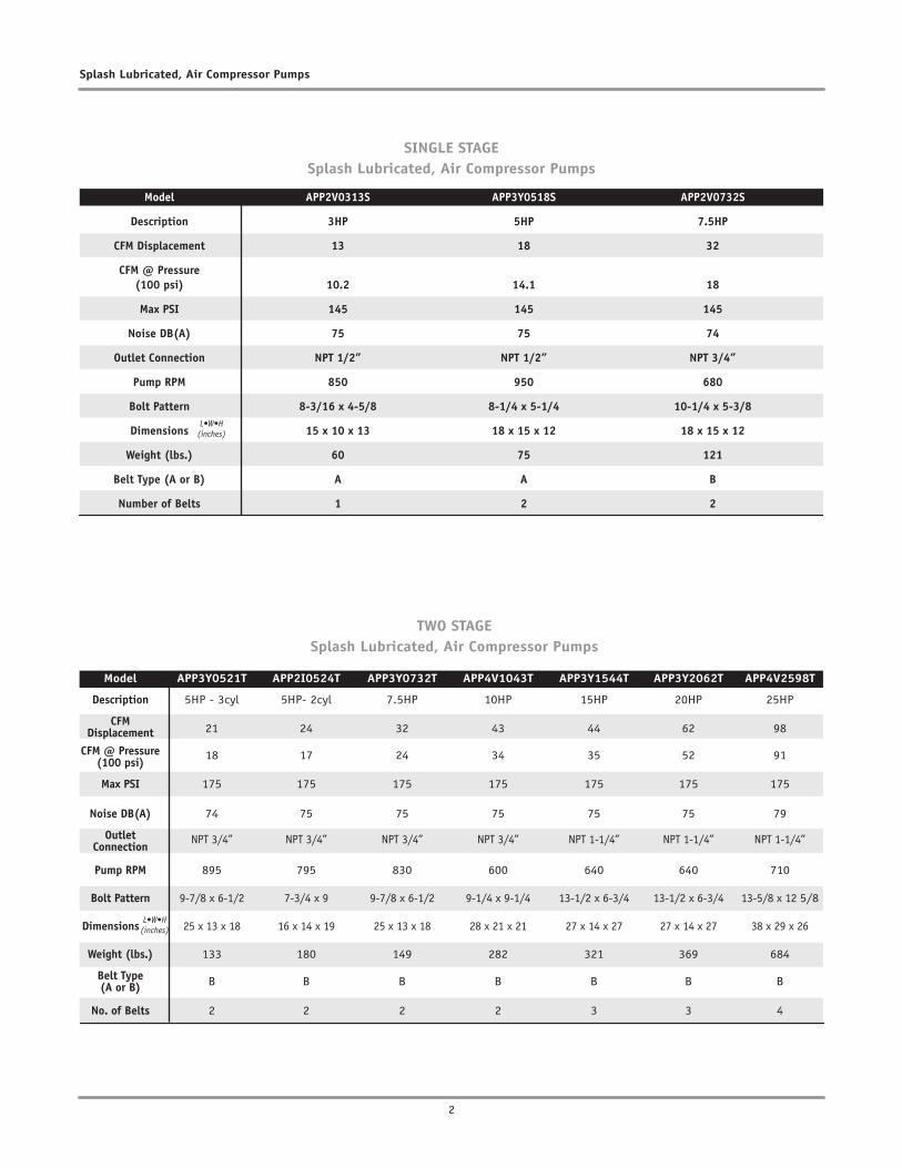
Model APP2V0313S APP3Y0518S APP2V0732S
Description 3HP 5HP 7.5HP
CFM Displacement 13 18 32
CFM @ Pressure (100 psi) 10.2 14.1 18
Max PSI 145 145 145
Noise DB(A) 75 75 74
Outlet Connection NPT 1/2” NPT 1/2” NPT 3/4”
Pump RPM 850 950 680
Bolt Pattern 8-3/16 x 4-5/8 8-1/4 x 5-1/4 10-1/4 x 5-3/8
Dimensions 15 x 10 x 13 18 x 15 x 12 18 x 15 x 12
Weight (lbs.) 60 75 121
Belt Type (A or B) A A B
Number of Belts 1 2 2
SINGLE STAGESplash Lubricated, Air Compressor Pumps
TWO STAGESplash Lubricated, Air Compressor Pumps
(inches)
Model APP3Y0521T APP2I0524T APP3Y0732T APP4V1043T APP3Y1544T APP3Y2062T APP4V2598T
Description 5HP - 3cyl 5HP- 2cyl 7.5HP 10HP 15HP 20HP 25HP
CFM Displacement 21 24 32 43 44 62 98
CFM @ Pressure (100 psi)
18 17 24 34 35 52 91
Max PSI 175 175 175 175 175 175 175
Noise DB(A) 74 75 75 75 75 75 79
Outlet Connection
NPT 3/4” NPT 3/4” NPT 3/4” NPT 3/4” NPT 1-1/4” NPT 1-1/4” NPT 1-1/4”
Pump RPM 895 795 830 600 640 640 710
Bolt Pattern 9-7/8 x 6-1/2 7-3/4 x 9 9-7/8 x 6-1/2 9-1/4 x 9-1/4 13-1/2 x 6-3/4 13-1/2 x 6-3/4 13-5/8 x 12 5/8
Dimensions 25 x 13 x 18 16 x 14 x 19 25 x 13 x 18 28 x 21 x 21 27 x 14 x 27 27 x 14 x 27 38 x 29 x 26
Weight (lbs.) 133 180 149 282 321 369 684
Belt Type (A or B) B B B B B B B
No. of Belts 2 2 2 2 3 3 4
(inches)
3
Operating Instructions
SafetyThis manual contains very important information to know and understand. This is provided for SAFETY and to PREVENT EQUIPMENT PROBLEMS. To help un-derstand this information, observe the following:
Danger indicates an imminently hazardous situation which, if not
avoided, will result in death or serious injury.
Warning indicates a potentially hazardous situation which, if not
avoided, could result in death or serious injury.
Caution indicates a potentially hazardous situation which, if not
avoided, may result in minor or moderate injury.
Notice indicates important infor-mation, that if not followed, may
cause damage to equipment.
Basic Guidelines 1. Allow only trained, authorized persons who
have read and understood these operating instructions to use this compressor pump. Fail-ure to follow the instructions, procedures and safety precautions in this manual can result in accidents and injuries.
2. NEVER start or operate the compressor pump under unsafe conditions. Tag the compres-sor, disconnect and lock out all power to it to prevent accidental start-up until the condition is corrected.
3. Install, use and operate the compressor pump only in full compliance with all pertinent OSHA regulations and all applicable Federal, State & Local Codes, standards and regulations.
4. NEVER modify the compressor pump and/or controls in any way.
5. Keep a first aid kit in a convenient place. Seek medical assistance promptly in case of injury. Avoid infection by caring for any small cuts and burns promptly.
Breathable Air 1. NEVER use air from this compressor pump for
breathable air except in full compliance with OSHA Standards 29 CFR 1910 and any other Federal, State or Local codes or regulations.
MANUAL
Read all manuals included with this product carefully. Be thoroughly familiar with the controls and the proper use of the equipment.
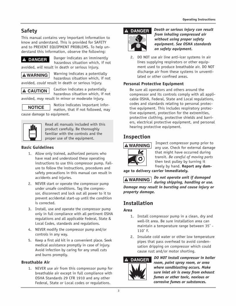
Death or serious injury can result from inhaling compressed air without using proper safety equipment. See OSHA standards on safety equipment.
2. DO NOT use air line anti-icer systems in air lines supplying respirators or other equip-ment used to produce breathable air. DO NOT discharge air from these systems in unventi-lated or other confined areas.
Personal Protective EquipmentBe sure all operators and others around the compressor and its controls comply with all appli-cable OSHA, Federal, State and Local regulations, codes and standards relating to personal protec-tive equipment. This includes respiratory protec-tive equipment, protection for the extremities, protective clothing, protective shields and barri-ers, electrical protective equipment, and personal hearing protective equipment.
Inspection Inspect compressor pump prior to
any use. Check for external damage that might have occurred during transit. Be careful of moving parts then test pulley by turning it freely by hand. Report any dam-
age to delivery carrier immediately.
Do not operate unit if damaged during shipping, handling or use.
Damage may result in bursting and cause injury or property damage.
Installation Area 1. Install compressor pump in a clean, dry and
well-lit area. Be sure installation area can maintain a temperature range between 35˚ - 110˚ F.
2. Insulate cold water or other low temperature pipes that pass overhead to avoid conden-sation dripping on compressor which could cause rust and/or motor shorting.
DO NOT install compressor in boiler room, paint spray room, or area where sandblasting occurs. Make sure inlet air is away from exhaust fumes or other toxic, noxious or corrosive fumes or substances.
4
Splash Lubricated, Air Compressor Pumps
3. If acid is used in operating environmentor air is dust laden, pipe intake to outside,fresh air. Increase pipe size by one size forevery 20 feet of run. Be sure to install pro-tective hood around intake filter.
4. In operating environments where excessivewater, oil, dirt, acid or alkaline fumes arepresent, a TEFC (totally enclosed, fan cooled)motor is recommended. Check nameplate formotor type.
5. Allow sufficient space around compressorpump for maintenance access. Mount unitwith pulley towards wall and leave a mini-mum of 15 inches of clearance.
6. Use shims to level compressor if installationarea is not flat. This will avoid excessivevibration and premature pump wear.
Piping
Safety Steps
1. Install appropriate flow-limiting valves asnecessary according to pipe size(s) used andrun lengths. This will reduce pressure in caseof hose failure, per OSHA Standard 29 CFR1926.302(b)(7).
2. Flow-limiting valves are listed by pipe sizeand rated CFM. Select appropriate valvesaccordingly, in accordance with the manufac-turer’s recommendations.
Tank Installation1. Place tank feet on 1/4” thick rubber pads.
Thicker padding will increase vibration andthe possibility of cracking the tank or otherunit damage. Do not place unit on dirt flooror uneven surface.
2. Fasten anchor bolts snugly but do not overtight-en so normal vibration will not damage unit.
Compressor unit is top heavy and must be bolted to solid, flat surface
to avoid falling and premature pump wear. Splash lubrication will not operate properly if unit is not level.
Pump Installation
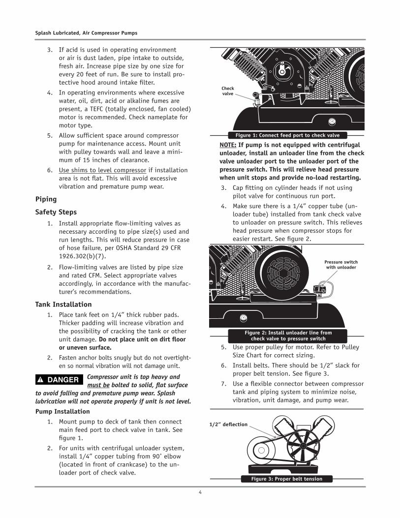
1. Mount pump to deck of tank then connectmain feed port to check valve in tank. Seefigure 1.
2. For units with centrifugal unloader system,install 1/4” copper tubing from 90˚ elbow(located in front of crankcase) to the un-loader port of check valve.
NOTE: If pump is not equipped with centrifugal unloader, install an unloader line from the check valve unloader port to the unloader port of the pressure switch. This will relieve head pressure when unit stops and provide no-load restarting.
3. Cap fitting on cylinder heads if not usingpilot valve for continuous run port.
4. Make sure there is a 1/4” copper tube (un-loader tube) installed from tank check valveto unloader on pressure switch. This relieveshead pressure when compressor stops foreasier restart. See figure 2.
5. Use proper pulley for motor. Refer to Pulley Size Chart for correct sizing.
6. Install belts. There should be 1/2” slack for proper belt tension. See figure 3.
7. Use a flexible connector between compressor tank and piping system to minimize noise, vibration, unit damage, and pump wear.
Figure 1: Connect feed port to check valve
Check valve
Figure 2: Install unloader line from check valve to pressure switch
Pressure switch with unloader
Figure 3: Proper belt tension
1/2” deflection
5
Operating Instructions
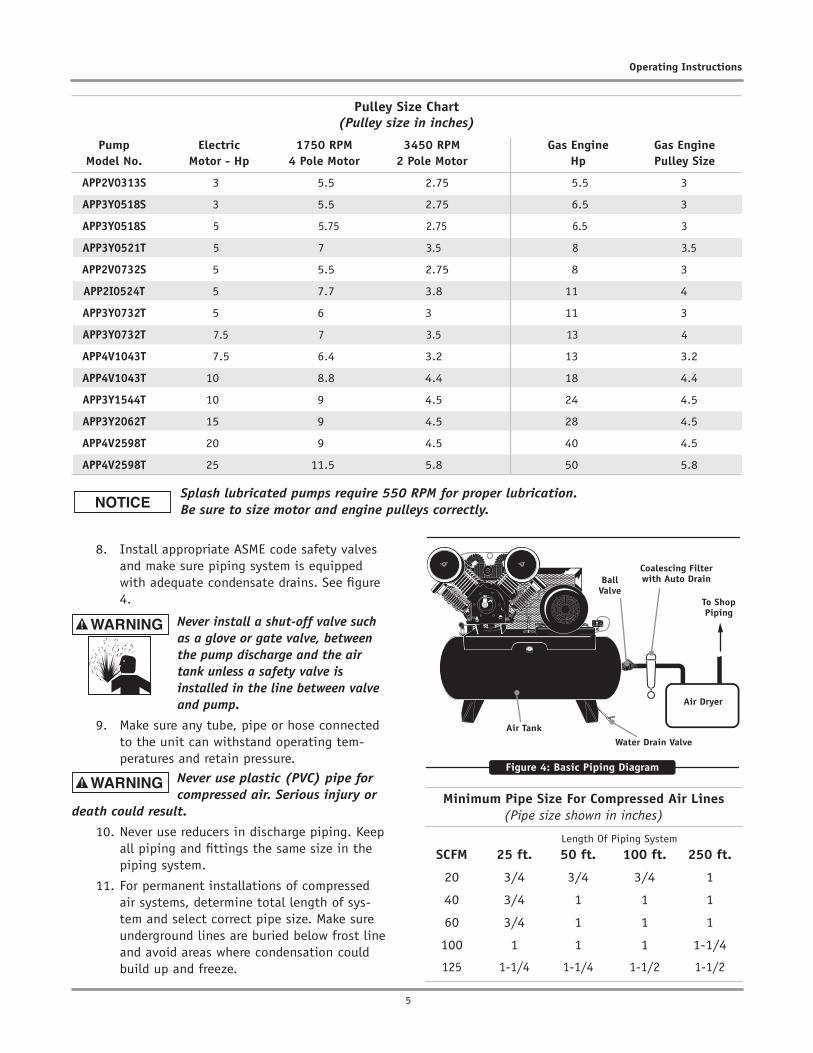
8. Install appropriate ASME code safety valvesand make sure piping system is equippedwith adequate condensate drains. See figure4.
Never install a shut-off valve such as a glove or gate valve, between the pump discharge and the air tank unless a safety valve is installed in the line between valve and pump.
9. Make sure any tube, pipe or hose connectedto the unit can withstand operating tem-peratures and retain pressure.
Never use plastic (PVC) pipe for compressed air. Serious injury or
death could result.
10. Never use reducers in discharge piping. Keepall piping and fittings the same size in thepiping system.
11. For permanent installations of compressedair systems, determine total length of sys-tem and select correct pipe size. Make sureunderground lines are buried below frost lineand avoid areas where condensation couldbuild up and freeze.
Ball Valve
Water Drain ValveAir Tank
Air Dryer
Coalescing Filter with Auto Drain
To Shop Piping
Figure 4: Basic Piping Diagram
Minimum Pipe Size For Compressed Air Lines(Pipe size shown in inches)
Length Of Piping System
SCFM 25 ft. 50 ft. 100 ft. 250 ft.
20 3/4 3/4 3/4 1
40 3/4 1 1 1
60 3/4 1 1 1
100 1 1 1 1-1/4
125 1-1/4 1-1/4 1-1/2 1-1/2
Pulley Size Chart(Pulley size in inches)
Pump Electric 1750 RPM 3450 RPM Gas Engine Gas EngineModel No. Motor - Hp 4 Pole Motor 2 Pole Motor Hp Pulley Size
APP2V0313S 3 5.5 2.75 5.5 3
APP3Y0518S 3 5.5 2.75 6.5 3
APP3Y0518S 5 5.75 2.75 6.5 3
APP3Y0521T 5 7 3.5 8 3.5
APP2V0732S 5 5.5 2.75 8 3
APP2I0524T 5 7.7 3.8 11 4
APP3Y0732T 5 6 3 11 3
APP3Y0732T 7.5 7 3.5 13 4
APP4V1043T 7.5 6.4 3.2 13 3.2
APP4V1043T 10 8.8 4.4 18 4.4
APP3Y1544T 10 9 4.5 24 4.5
APP3Y2062T 15 9 4.5 28 4.5
APP4V2598T 20 9 4.5 40 4.5
APP4V2598T 25 11.5 5.8 50 5.8
Splash lubricated pumps require 550 RPM for proper lubrication. Be sure to size motor and engine pulleys correctly.

6
Splash Lubricated, Air Compressor Pumps
12. Test entire piping system before undergroundlines are buried. Be sure to find and repairall leaks before using compressor.
Never exceed recommended pressure or speed while operating
compressor.
Be sure to install beltguard on compressor unit after pump installation is complete.
OperationSafety Rules
1. Make sure all operators receive product train-ing, read and understand all instructions.
Keep all flammable, combustible, poisonous and noxious materials away from operating area. Make sure there are no oily rags, trash, leaves, litter or other combustible materials in operating area. Keep
suitable, fully charged fire extinguishers nearby when servicing and operating the compressor.
2. NEVER allow modifications to compressor struc-ture or controls.
3. Keep all ignition sources away from exposedelectrical parts.
4. Keep all persons clear of compressor duringstart-up and operation.
5. NEVER operate the compressor with the fan,coupling or other guards removed.
6. DO NOT engage in horseplay with air hoses asdeath or serious injury may result.
7. Make sure to provide adequate ventilationand use proper lubricant while operating thecompressor. If lubricant or other combustiblesubstances are spilled, clean up immediately.
8. When checking or adding lubricant or when re-filling air line anti-icer systems with antifreezecompound, shut off compressor and allow it tocool. Keep sparks, flames and other ignitionsources away and DO NOT permit smoking in thevicinity.
9. Stop compressor and disconnect power if ahazardous condition arises.
10. Wear snug fitting clothing and confine long hairwhen around compressor. Keep all body partsand clothing away from couplings, flywheel andother moving parts of the equipment.
Keep all persons away from the discharge opening of hoses or tools or other points of compressed air discharge. If the machine is installed in an enclosed area, be sure to vent the relief valve outside
of the structure or to an unoccupied area.
11. DO NOT use air tools that are rated below themaximum rating of the compressor. Selectair tools, air hoses, pipes, valves, filters andother fittings accordingly. DO NOT exceedmanufacturer’s rated safe operating pressuresfor these items.
12. Make sure all hose connections are adequate-ly secured to prevent tools or hose ends frombeing accidentally disconnected.
Start-Up1. This unit may or may not contain oil when
shipped. Be sure to check for proper oil levelbefore operating the compressor. Oil shouldbe in center of site glass. See figure 5.
Use only Airbase Industries oil (PN: APOL03000G1). Use of any
other product will cause product damage and void the warranty.
2. Check for proper belt tension. There shouldbe 1/2 inch slack. Refer to figure 3, pg. 4.
Always make sure main power is off before touching belts or other moving parts of compressor.
3. Push power switch to make sure system isworking.
4. Ensure motor rotation is correct. Refer tounit operating instructions if necessary.
Figure 5: Check proper oil level
Oil level should be to center of red circle in site glass
7
Operating Instructions
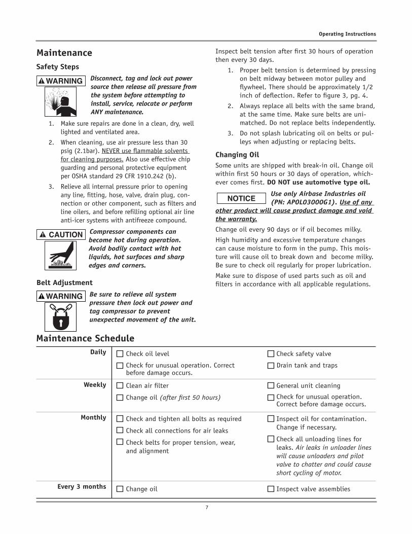
MaintenanceSafety Steps
Disconnect, tag and lock out power source then release all pressure from the system before attempting to install, service, relocate or perform ANY maintenance.
1. Make sure repairs are done in a clean, dry, welllighted and ventilated area.
2. When cleaning, use air pressure less than 30psig (2.1bar). NEVER use flammable solventsfor cleaning purposes. Also use effective chipguarding and personal protective equipmentper OSHA standard 29 CFR 1910.242 (b).
3. Relieve all internal pressure prior to openingany line, fitting, hose, valve, drain plug, con-nection or other component, such as filters andline oilers, and before refilling optional air lineanti-icer systems with antifreeze compound.
Compressor components can become hot during operation. Avoid bodily contact with hot liquids, hot surfaces and sharp edges and corners.
Belt Adjustment
Be sure to relieve all system pressure then lock out power and tag compressor to prevent unexpected movement of the unit.
Inspect belt tension after first 30 hours of operation then every 30 days.
1. Proper belt tension is determined by pressingon belt midway between motor pulley andflywheel. There should be approximately 1/2inch of deflection. Refer to figure 3, pg. 4.
2. Always replace all belts with the same brand,at the same time. Make sure belts are uni-matched. Do not replace belts independently.
3. Do not splash lubricating oil on belts or pul-leys when adjusting or replacing belts.
Changing OilSome units are shipped with break-in oil. Change oil within first 50 hours or 30 days of operation, which-ever comes first. DO NOT use automotive type oil.
Use only Airbase Industries oil (PN: APOL03000G1). Use of any
other product will cause product damage and void the warranty.
Change oil every 90 days or if oil becomes milky.
High humidity and excessive temperature changes can cause moisture to form in the pump. This mois-ture will cause oil to break down and become milky. Be sure to check oil regularly for proper lubrication.
Make sure to dispose of used parts such as oil and filters in accordance with all applicable regulations.
Maintenance ScheduleDaily
Weekly
Monthly
Every 3 months
Check oil level
Check for unusual operation. Correct before damage occurs.
Change oil
Clean air filter
Change oil (after first 50 hours)
Check and tighten all bolts as required
Check all connections for air leaks
Check belts for proper tension, wear, and alignment
Check safety valve
Drain tank and traps
Inspect valve assemblies
General unit cleaning
Check for unusual operation. Correct before damage occurs.
Inspect oil for contamination. Change if necessary.
Check all unloading lines for leaks. Air leaks in unloader lines will cause unloaders and pilot valve to chatter and could cause short cycling of motor.

8
Splash Lubricated, Air Compressor Pumps
Troubleshooting ChartProblem Possible Causes Resolutions
Low air pressure
Overheating
1. Clogged inlet filter2. Air leak(s) in system
3. Application exceeds rated airoutput of compressor
4. Cylinder head valves notsealing
5. Insufficient power
1. Duty cycle exceeded2. Improper rotation
3. Head valve(s) not seatingproperly
4. Blown cylinder head gasket(s)5. Restriction in head,
intercooler or check valve6. Low oil
7. Dirt in intercooler fins orcylinder fins
8. Poor ventilation / ambienttemperature too high
1. Disassemble valve, clean thorougly2. Use soapy water to locate leaks, replace or tighten
threaded parts3. Check CFM requirements, change tool or use compressor
with higher air output4. Remove valves from cylinder head, repair or replace as
necessary5. Check power supply, rewire as necessary
1. Keep duty cycle at 60/40 to maintain pump life2. When facing flywheel, ensure counter-clockwise
rotation3. Clean or replace
4. Replace gasket(s)5. Clear blockage
6. Add oil. Ensure oil level is at middle of site glass. Seefigure 5, pg. 6.
Use only Airbase Industries oil (PN: APOL03000G1). Use of any other
product will cause product damage and void the warranty.
7. Use low pressure air to blow dirt away from compressor
8. Increase ventilation around operating area. Ensurecompressor has adequate clear space from walls andother possible obstructions. Ambient temperatureshould not exceed 110˚ F.
Airbase Industries makes the following WARRANTY STATEMENT:
1. THAT EACH BARE COMPRESSOR PUMP UNIT TO BE FREE FROM DEFECTS IN MATERIAL, WORKMANSHIP, AND PARTS FOR 2 YEARS FOR THE UNIT FROM THE DATEOF PURCHASE. Airbase Industries (and each of its subsidiaries) is not responsible for downtime during warranty service. If downtime is necessary, it isthe Purchaser’s discretion and obligation (at Purchaser’s expense) to have a redundant COMPRESSOR PUMP. Warranty repairs shall not include freight costs.Purchaser is responsible for returning unit to Airbase Industries. This PUMP MUST have Airbase Industries Lubricant Synthetic exclusively, the same whichmust be purchased from Airbase Industries. (Mixing different brands of oil will void this warranty). A service kit must be purchased from Emax or an Emaxdealer for this warranty to apply. Service kits contain an air filter and synthetic oil that must be changed annually. Annual proof of purchase of all oil programs mustbe maintained by the original purchaser of the compressor pump. If the unit runs out of oil, this warranty is void. Failure to fully comply with this warrantyand fully comply with the manual herein will void this warranty.
Exclusions include: service such as OIL CHANGES, FILTER REPLACEMENTS, GASKET TIGHTENING TO CORRECT OIL SEEPAGE or DRIVE BELT TIGHTENING and VALVECLEANING and are not covered under warranty.
Warranty shall be void under the following conditions: Failure to routinely change oil and to maintain a clean filter, or exceeding 70% duty cycle resulting inoverheating and excessive wear and tear, or exposing electrical components to rain or water, or installing the unit in a hostile environment such as acid vaporsor any caustic or abrasive matter that may be ingested into the pump, or installing the unit in an enclosed area where lack of cooling ventilation is present,such as in boiler or equipment rooms where the ambient air exceeds 100˚F.
Airbase Industries shall not be held liable for any malfunction of BARE COMPRESSOR PUMP UNIT caused by failure or improper use and/or maintenance of othercompressor components manufactured by others.
2. GENERAL PROVISIONS: Airbase Industries (and each of its subsidiaries) is not responsible for downtime during warranty service. If downtime is necessary, it is thePurchaser’s discretion and obligation (at Purchaser’s expense) to have a redundant compressor. Warranty repairs shall not include freight costs. If necessary, thePurchaser is responsible for returning unit and/or applicable part(s) to Airbase Industries.
Exclusions include: service such as OIL CHANGES, FILTER REPLACEMENTS, GASKET TIGHTENING TO CORRECT OIL SEEPAGE or DRIVE BELT TIGHTENING and VALVECLEANING and are not covered under warranty.
Further Exclusions include failure to fully and completely follow the guidelines set forth in the manual. Of specific note is where a product is used where granite and/or concrete work is performed or conditions are dusty and the product is required to be housed in a separate room from the adverse conditions where the product hasaccess to fresh air intake.
Parts used for warranty purposes must be supplied by Airbase Industries. Warranty work will be performed by an approved Airbase Industries Technician. If any maintenance (other than routine maintenance) is performed by a non-approved Airbase Industries Technician, written pre-approval must be obtained from Airbase Industries to prevent voiding this Warranty. Failure to fully comply with this warranty and fully comply with the manual herein will void this warranty.
All warranties are nontransferable.
The Oil Purchase Program is effective as of January 1, 2011.
APP2V0313S – EC3
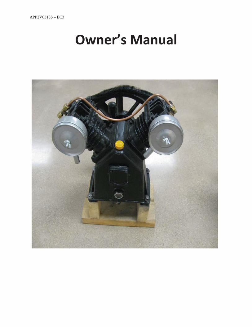
Owner’s Manual
APP2V0313S – EC3
Introduction
In order to receive maximum performance and long life from your compressor, the following instructions should be carefully read and all points regarding installation and operation of the unit should be noted and observed. A careful reading of this manual, prior to connecting anything to the motor of the compressor, will pay dividends in terms of trouble-free operation.
Inspection
Check for possible damage in transit and see that the pulley turns freely by hand. Report any damage to the delivery carrier at once.
Location
Select a clean, dry, and well-lit location. In cold climates, the compressor should be installed in a heated building. Insulate cold water or other low temperature pipes that pass overhead to avoid the possible collection and dripping of condensate onto the compressor and motor that could cause rusting or the motor shorting out. DO NOT install the compressor in a boiler room, paint spray room, or area where sandblasting is carried on. If air in the area where the compressor is to be installed is acid or dust laden, the compressor intake should be piped to the outside. This intake pipe should increase in size for every twenty (20) feet of run and the intake filters should be installed at the end of the pipes with a hood to protect them from the elements. Special size filters are required for that pipe.
If the compressor has to be located where the motor will be exposed to appreciable quantities of water, dirt, oil, acid, or alkaline fumes, the motor must be of special construction to avoid rapid deterioration; i.e. TEFC
Unless the base is exactly level, shims will be required. Any space between the base and foot of the tank should be shimmed rather than drawing the foot down, thus placing strain on the unit. When is properly shimmed, vibration will be at a minimum. Also use a ¼’’ or less rubber pad under each foot to help with vibration.
Allow sufficient space around the compressor so that it is accessible from all sides for maintenance. Mount the unit with the pulley side toward the wall, but at least 18 inches from it.
Hooking up the pump
Mount pump to the deck of the tank. We recommend using angle iron to raise the pumpabove the deck, to allow for better crankcase cooling.Hook up main feed tube from the ½’’ flare fitting to the check valve in the tank.
APP2V0313S – EC3
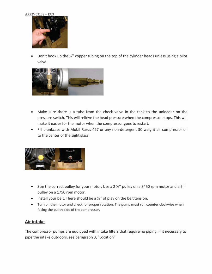
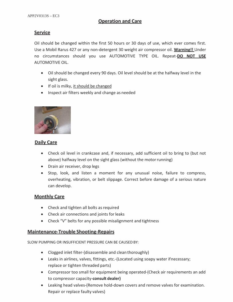
Don’t hook up the ¼’’ copper tubing on the top of the cylinder heads unless using a pilotvalve.
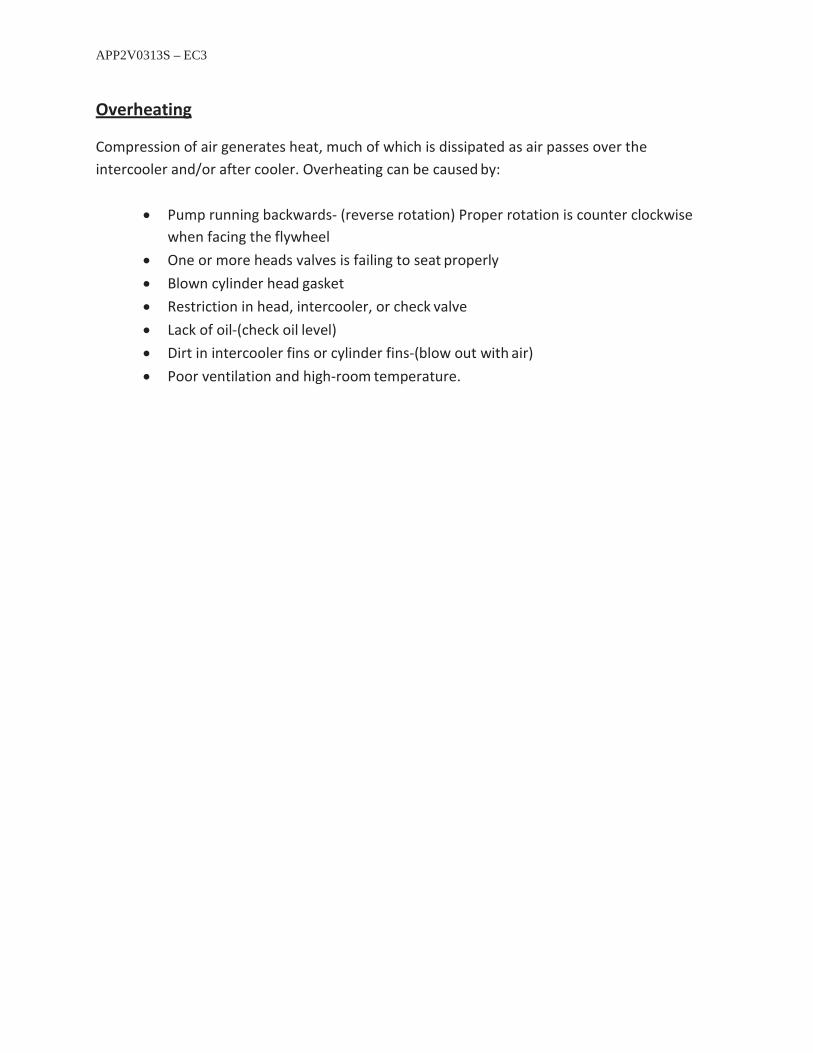
Make sure there is a tube from the check valve in the tank to the unloader on thepressure switch. This will relieve the head pressure when the compressor stops. This willmake it easier for the motor when the compressor goes to restart.Fill crankcase with Mobil Rarus 427 or any non-detergent 30 weight air compressor oilto the center of the sight glass.
Size the correct pulley for your motor. Use a 2 ½’’ pulley on a 3450 rpm motor and a 5’’pulley on a 1750 rpm motor.Install your belt. There should be a ½’’ of play on the belt tension.Turn on the motor and check for proper rotation. The pump must run counter clockwise whenfacing the pulley side of the compressor.
Air intake
The compressor pumps are equipped with intake filters that require no piping. If it necessary to pipe the intake outdoors, see paragraph 3, “Location”

APP2V0313S – EC3
Pipe Connection
A flexible connector should be used between the compressor tank and building piping or connection to after cooler or other similar equipment in order to minimize noise, vibration, vibration damage, and wear and tear.
Caution
Never install a shut-off valve, such as a glove or gate valve, between the compressor anddischarge opening and the receiver unless a safety valve is installed in the line betweenthis valve and the compressor.Never operate the pump at pressures or speeds in excess of those recommended by thefactory. (900rpm or 145 psi)
Tank
Tank feet should be place on vibration isolator pads available through your dealer. Anchor bolts should be gently snugged, but not tight, to allow for vibration. Remember, the bolt is only a guide to hold the compressor in place. Do not over tighten the legs of the tank against the pads…it will damage your tank. Caution: Do not set tank on dirt. Over time, the tank will tilt causing the pump to fail from in adequate lubrication.
Starting
Check the oil level before startingTurn compressor over a few revolutions by hand to make sure that everything is free.Check the belt tensionRemove tools, rags, and any other objects from the vicinity of the compressorNever put hands on the belt of idle units, unless the motor is switched off and lockedoutNote the direction of the arrow on the flywheel and be sure that the direction ofrotation is correct when the machine is started. Correct direction is counter-clockwisewhen standing facing the flywheel. Air should be drawn through the intercooler ontothe cylinders for maximum cooling.
APP2V0313S – EC3
Operation and Care
Service
Oil should be changed within the first 50 hours or 30 days of use, which ever comes first. Use a Mobil Rarus 427 or any non-detergent 30 weight air compressor oil. Warning!! Under no circumstances should you use AUTOMOTIVE TYPE OIL. Repeat-DO NOT USE AUTOMOTIVE OIL.
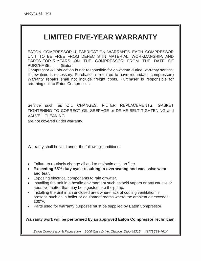
Oil should be changed every 90 days. Oil level should be at the halfway level in the sight glass. If oil is milky, it should be changed Inspect air filters weekly and change as needed
Daily Care
Check oil level in crankcase and, if necessary, add sufficient oil to bring to (but not above) halfway level on the sight glass (without the motor running) Drain air receiver, drop legs Stop, look, and listen a moment for any unusual noise, failure to compress, overheating, vibration, or belt slippage. Correct before damage of a serious nature can develop.
Monthly Care
Check and tighten all bolts as required Check air connections and joints for leaks Check “V” belts for any possible misalignment and tightness
Maintenance-Trouble Shooting-Repairs
SLOW PUMPING OR INSUFFICIENT PRESSURE CAN BE CAUSED BY:
Clogged inlet filter-(disassemble and clean thoroughly) Leaks in airlines, valves, fittings, etc.-(Located using soapy water if necessary; replace or tighten threaded parts) Compressor too small for equipment being operated-(Check air requirements an add to compressor capacity-consult dealer) Leaking head valves-(Remove hold-down covers and remove valves for examination. Repair or replace faulty valves)
APP2V0313S – EC3
Overheating
Compression of air generates heat, much of which is dissipated as air passes over the intercooler and/or after cooler. Overheating can be caused by:
Pump running backwards- (reverse rotation) Proper rotation is counter clockwisewhen facing the flywheelOne or more heads valves is failing to seat properlyBlown cylinder head gasketRestriction in head, intercooler, or check valveLack of oil-(check oil level)Dirt in intercooler fins or cylinder fins-(blow out with air)Poor ventilation and high-room temperature.
APP2V0313S – EC3
LIMITED FIVE-YEAR WARRANTY
EATON COMPRESSOR & FABRICATION WARRANTS EACH COMPRESSOR UNIT TO BE FREE FROM DEFECTS IN MATERIAL, WORKMANSHIP, AND PARTS FOR 5 YEARS ON THE COMPRESSOR FROM THE DATE OF PURCHASE. (EatonCompressor & Fabrication is not responsible for downtime during warranty service. If downtime is necessary, Purchaser is required to have redundant compressor.) Warranty repairs shall not include freight costs. Purchaser is responsible for returning unit to Eaton Compressor.
Service such as OIL CHANGES, FILTER REPLACEMENTS, GASKET TIGHTENING TO CORRECT OIL SEEPAGE or DRIVE BELT TIGHTENING and VALVE CLEANINGare not covered under warranty.
Warranty shall be void under the following conditions:
Failure to routinely change oil and to maintain a clean filter.Exceeding 65% duty cycle resulting in overheating and excessive wear and tear. Exposing electrical components to rain or water.Installing the unit in a hostile environment such as acid vapors or any caustic or abrasive matter that may be ingested into the pump.Installing the unit in an enclosed area where lack of cooling ventilation is present. such as in boiler or equipment rooms where the ambient air exceeds100oF.Parts used for warranty purposes must be supplied by EatonCompressor.
Warranty work will be performed by an approved Eaton CompressorTechnician.
Eaton Compressor & Fabrication 1000 Cass Drive, Clayton, Ohio 45315 (877) 283-7614
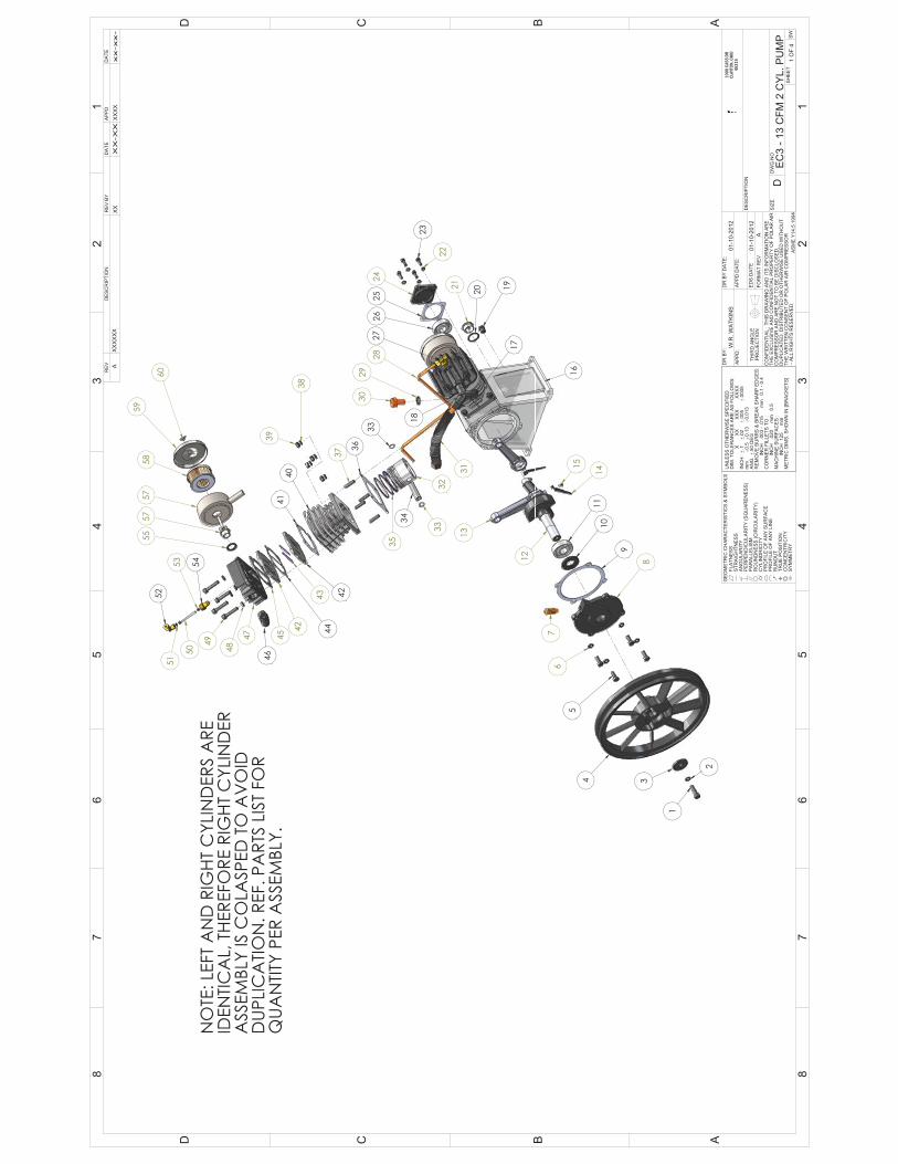

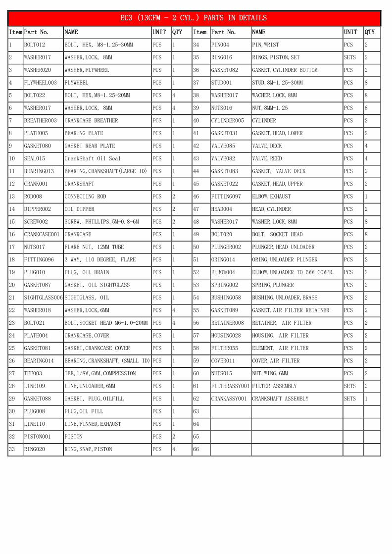
EC3 (13CFM - 2 CYL.) PARTS IN DETAILS
Item Part No. NAME UNIT QTY Item Part No. NAME UNIT QTY
1 BOLT012 BOLT, HEX, M8-1.25-30MM PCS 1 34 PIN004 PIN,WRIST PCS 2
2 WASHER017 WASHER,LOCK, 8MM PCS 1 35 RING016 RINGS,PISTON,SET SETS 2
3 WASHER020 WASHER,FLYWHEEL PCS 1 36 GASKET082 GASKET,CYLINDER BOTTOM PCS 2
4 FLYWHEEL003 FLYWHEEL PCS 1 37 STUD001 STUD,8M-1.25-30MM PCS 8
5 BOLT022 BOLT, HEX,M8-1.25-20MM PCS 4 38 WASHER017 WACHER,LOCK,8MM PCS 8
6 WASHER017 WASHER,LOCK, 8MM PCS 4 39 NUTS016 NUT,8MM-1.25 PCS 8
7 BREATHER003 CRANKCASE BREATHER PCS 1 40 CYLINDER005 CYLINDER PCS 2
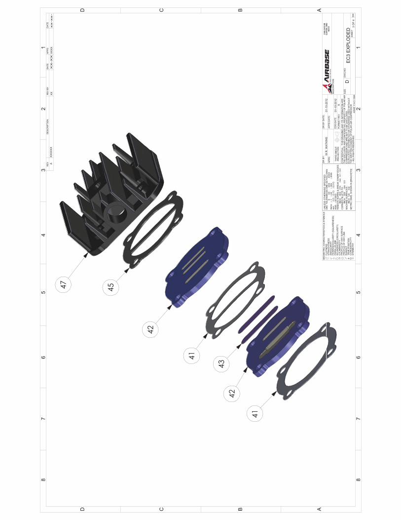
8 PLATE005 BEARING PLATE PCS 1 41 GASKET031 GASKET,HEAD,LOWER PCS 2
9 GASKET080 GASKET REAR PLATE PCS 1 42 VALVE085 VALVE,DECK PCS 4
10 SEAL015 CrankShaft Oil Seal PCS 1 43 VALVE082 VALVE,REED PCS 4
11 BEARING013 BEARING,CRANKSHAFT(LARGE ID) PCS 1 44 GASKET083 GASKET, VALVE DECK PCS 2
12 CRANK001 CRANKSHAFT PCS 1 45 GASKET022 GASKET,HEAD,UPPER PCS 2
13 ROD008 CONNECTING ROD PCS 2 46 FITTING097 ELBOW,EXHAUST PCS 1
14 DIPPER002 OIL DIPPER PCS 2 47 HEAD004 HEAD,CYLINDER PCS 2
15 SCREW002 SCREW, PHILLIPS,5M-0.8-6M PCS 2 48 WASHER017 WASHER,LOCK,8MM PCS 8
16 CRANKCASE001 CRANKCASE PCS 1 49 BOLT020 BOLT, SOCKET HEAD PCS 8
17 NUTS017 FLARE NUT, 12MM TUBE PCS 1 50 PLUNGER002 PLUNGER,HEAD UNLOADER PCS 2
18 FITTING096 3 WAY, 110 DEGREE, FLARE PCS 1 51 ORING014 ORING,UNLOADER PLUNGER PCS 2
19 PLUG010 PLUG, OIL DRAIN PCS 1 52 ELBOW004 ELBOW,UNLOADER TO 6MM COMPR. PCS 2
20 GASKET087 GASKET, OIL SIGHTGLASS PCS 1 53 SPRING002 SPRING,PLUNGER PCS 2
21 SIGHTGLASS006 SIGHTGLASS, OIL PCS 1 54 BUSHING058 BUSHING,UNLOADER,BRASS PCS 2
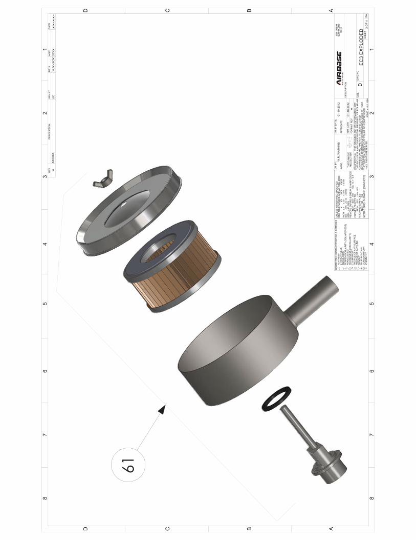
22 WASHER018 WASHER,LOCK,6MM PCS 4 55 GASKET089 GASKET,AIR FILTER RETAINER PCS 2
23 BOLT021 BOLT,SOCKET HEAD M6-1.0-20MM PCS 4 56 RETAINER008 RETAINER, AIR FILTER PCS 2
24 PLATE004 CRANKCASE,COVER PCS 1 57 HOUSING028 HOUSING, AIR FILTER PCS 2
25 GASKET081 GASKET,CRANKCASE COVER PCS 1 58 FILTER055 ELEMENT, AIR FILTER PCS 2
26 BEARING014 BEARING,CRANKSHAFT,(SMALL ID) PCS 1 59 COVER011 COVER,AIR FILTER PCS 2
27 TEE003 TEE,1/8M,6MM,COMPRESSION PCS 1 60 NUTS015 NUT,WING,6MM PCS 2
28 LINE109 LINE,UNLOADER,6MM PCS 1 61 FILTERASSY001 FILTER ASSEMBLY SETS 2
29 GASKET088 GASKET, PLUG,OILFILL PCS 1 62 CRANKASSY001 CRANKSHAFT ASSEMBLY SETS 1
30 PLUG008 PLUG,OIL FILL PCS 1 63
31 LINE110 LINE,FINNED,EXHAUST PCS 1 64
32 PISTON001 PISTON PCS 2 65
33 RING020 RING,SNAP,PISTON PCS 4 66