splash proof phone - lup.lub.lu.se
TRANSCRIPT

ISRN LUTMDN/TMKT-01/5236
Splash Proof Phone Niclas Håkansson Björn Lekander

Splash Proof Phone
I

Splash Proof Phone
I
PREFACE This is a thesis for the degree Master of Science at the Division of Machine Design at the Department of Design Sciences, Lund University of Technology. The thesis was written at the Department of Advanced Mechanics at Ericsson Mobile Communications AB in Lund in the period of August 2000 to February 2001. The thesis is a study of a concept called “Splash Proof Phone”. We would like to thank some people that have supported us during the proceeding of this project. First of all we would like to thank our supervisor at Ericsson, Mr Matti Siivola, for valuable guidance through the master thesis. Further, we would like to thank Mr Fredrik Palmqvist, Manager Advanced Mechanics, and all of the employees at Advanced Mechanics for their helpfulness at any time. Also thanks to all employees at Ericsson that have helped us during this project. We would also like to thank Acting Prof. Robert Bjärnemo for help with the thesis writing. Lund, 22 February, 2001 Niclas Håkansson Björn Lekander

Splash Proof Phone
II
ABSTRACT The purpose of this thesis is to study the problem with water and moist getting into the phones and to present solutions that will protect the phone from these hazards. We are not aiming at doing a new ruggedized phone like the R310s, what we are interested in are solutions that are seen as quality improvements to standard phones. To utilize the knowledge within Ericsson regarding ruggedized phones we attended a Wet Meeting were we met the R310s and the R250PRO teams. To come up with new ideas we both looked at old solutions and used a brainstorming group. Altogether we came up with about 50 different solutions of which we developed 36 further. Due to lack of time we put the major part of our efforts on the acoustic devices and the keypad. To make prototypes of our solutions we contacted different suppliers and discussed with them what specification of requirements that we wanted. For testing we used a Rain Machine, which tested for the international ingression protection standard IPX2. The X2 class implies 3mm of rain per minute. Our tests show that concerning rain there is no problem with a splash proof membrane in front of the acoustical parts. The problem is the acoustics where the thicker membranes tend to block the sound; therefore we recommend further investigation regarding the thicker materials. Another solution for the speaker is to make it water proof. Hyonsoo has developed such a speaker, which we have tested with good results. For keypads we have come up with several different solutions of which the ones with hard tops were the most interesting. For the hard top concept we used the key-tree of today and moulded a TPU film in between to make it splash proof. We have made some in-house prototypes for the SIM-card reader and the battery connector, which have proven to work satisfactory. It should also be mentioned that we have looked at other parts of the phone but there hasn’t been any prototypes made even though we had some promising ideas. Today Ericsson can exchange the speaker and buzzer cloth for the lightest Gore membrane, the GAW 101. There won’t be any problem due to acoustical impedance or water ingression. As general guidelines we would recommend large radii and straight part lines between different parts of the phone. Avoid joints with more than two parts since it will be a problem to get it sealed due to tolerances. In the report we have listed solutions for acoustical parts, keypad, system IO, battery, SIM-card, antenna, volume button and joint frame/front. We are also recommending Ericsson to look further into the contact less charging technique and solutions for the multimedia slot.

Splash Proof Phone
III
TABLE OF CONTENTS
PREFACE… ....................................................................................................................... I
ABSTRACT ...................................................................................................................... II
TABLE OF CONTENTS ............................................................................................... III
1 INTRODUCTION ...................................................................................................... 1
1.1 PREREQUISITE................................................................................................. 1 1.2 BACKGROUND ................................................................................................ 1 1.3 PROBLEM .......................................................................................................... 1 1.4 OBJECTIVE ....................................................................................................... 1 1.5 SCOPE ................................................................................................................ 2 1.6 STRUCTURE OF THE REPORT ....................................................................... 2
2 APPROACH ............................................................................................................... 5
2.1 INTRODUCTION PHASE ................................................................................. 5 2.2 PRE-STUDY PHASE ......................................................................................... 5 2.3 FEASABILITY STUDY ..................................................................................... 5 2.4 CONSTRUCTION- AND TESTING PHASE .................................................... 5 2.5 CONCLUSION PHASE ..................................................................................... 6
3 TECHNICAL BACKGROUND AND NOMENCLATURE .................................. 7
3.1 MATERIALS ...................................................................................................... 7 3.1.1 Thermoplastics ................................................................................................ 7 3.1.2 Elastomers....................................................................................................... 8 3.1.3 Magnesium ...................................................................................................... 8
3.2 ACOUSTICS ...................................................................................................... 8 3.3 TESTING AND CLASSIFICATION ............................................................... 10
3.3.1 IP Coding ...................................................................................................... 10 3.3.2 Definition of “Splash Proof” ........................................................................ 11 3.3.3 Testing methods for water testing ................................................................. 11 3.3.4 Testing equipment used for Splash Proof testing .......................................... 12 3.3.5 Testing methods and equipment used for acoustic testing ............................ 13 3.3.6 Functional test .............................................................................................. 13
3.4 PRODUCTION ................................................................................................. 14 3.4.1 Multi-component moulding ........................................................................... 14 3.4.2 Laser welding ................................................................................................ 14 3.4.3 Assembly ....................................................................................................... 15
3.5 THE “ERICSSON R320S” PHONE .................................................................. 16 3.5.1 Structure ........................................................................................................ 16 3.5.2 Identified leaks .............................................................................................. 19 3.5.3 Hazards with water leaking .......................................................................... 20
3.6 SEALINGS IN RUGGEDIZED APPLICATIONS .......................................... 20
4 SUPPLIERS AND THEIR TECHNIQUES ........................................................... 23
4.1 FREMACH ....................................................................................................... 23 4.2 HYONSOO ....................................................................................................... 23

Splash Proof Phone
IV
4.3 GUMMIWERK KRAIBURG ........................................................................... 24 4.4 NOLATO SILIKONTEKNIK .......................................................................... 24 4.5 TAISEI PLAS ................................................................................................... 25 4.6 TOKIN CORPORATION ................................................................................. 26 4.7 W.L. GORE ....................................................................................................... 27
5 CONCEPTUAL DESIGNS ..................................................................................... 29
5.1 SPECIFICATIONS ........................................................................................... 29 5.2 VOLUME BUTTON ........................................................................................ 29
5.2.1 Gasket on existing button .............................................................................. 29 5.2.2 Sealing between button and front ................................................................. 30 5.2.3 Rubber gasket between button and front ...................................................... 30
5.3 KEYPAD .......................................................................................................... 30 5.3.1 Protective surface on the dome-plate ........................................................... 30 5.3.2 Inmould keypad ............................................................................................. 31 5.3.3 Inmould hardtops .......................................................................................... 31 5.3.4 Key-tree with silicone ................................................................................... 32 5.3.5 Unattached hardtop keypad .......................................................................... 32 5.3.6 Front foil ....................................................................................................... 33 5.3.7 Touch sensitive buttons ................................................................................. 34 5.3.8 Keypad laser welded into the front ............................................................... 34
5.4 BATTERY, SIM-CARD AND ANTENNA ..................................................... 35 5.4.1 Battery release catch..................................................................................... 35 5.4.2 Gasket around battery ................................................................................... 35 5.4.3 Lap gasket on battery .................................................................................... 36 5.4.4 Rubber plug for external antenna connector ................................................ 36 5.4.5 Antenna gasket and rear connector plug in one ........................................... 37 5.4.6 Battery-PCB cord connection. ...................................................................... 37 5.4.7 O-rings .......................................................................................................... 38
5.5 JOINT FRAME/FRONT ................................................................................... 38 5.5.1 Gasket in between ......................................................................................... 38 5.5.2 Radial gasket ................................................................................................. 39
5.6 LOUDSPEAKER .............................................................................................. 39 5.6.1 Water-resistant loudspeaker ......................................................................... 39 5.6.2 Gore membrane ............................................................................................ 40 5.6.3 Multi-mode actuators .................................................................................... 40
5.7 MICROPHONE/BUZZER ............................................................................... 41 5.7.1 Membranes .................................................................................................... 41 5.7.2 Trapped air principle .................................................................................... 41 5.7.3 Ingenious channels........................................................................................ 42 5.7.4 Coat channels with water repellent material. ............................................... 42
5.8 PCB ................................................................................................................... 43 5.8.1 Parylen .......................................................................................................... 43 5.8.2 Board shield .................................................................................................. 43
5.9 SYSTEM IO ...................................................................................................... 44 5.9.1 Sealed connector ........................................................................................... 44 5.9.2 Water proof cover ......................................................................................... 44 5.9.3 Corrosion-resistant coating .......................................................................... 45 5.9.4 Contact-less charging ................................................................................... 45
5.10 VENTILATION ................................................................................................ 46

Splash Proof Phone
V
5.10.1 Gore membrane ........................................................................................... 46 5.10.2 Power dry out ............................................................................................... 46
6 PROTOTYPES AND SIMULATIONS .................................................................. 47
6.1 PROTOTYPES MADE INHOUSE .................................................................. 47 6.1.1 Keypads ......................................................................................................... 47 6.1.2 Battery sealing .............................................................................................. 48 6.1.3 SIM card sealing ........................................................................................... 48 6.1.4 External antenna plug ................................................................................... 49 6.1.5 Ingenious channels........................................................................................ 50 6.1.6 Volume button ............................................................................................... 50
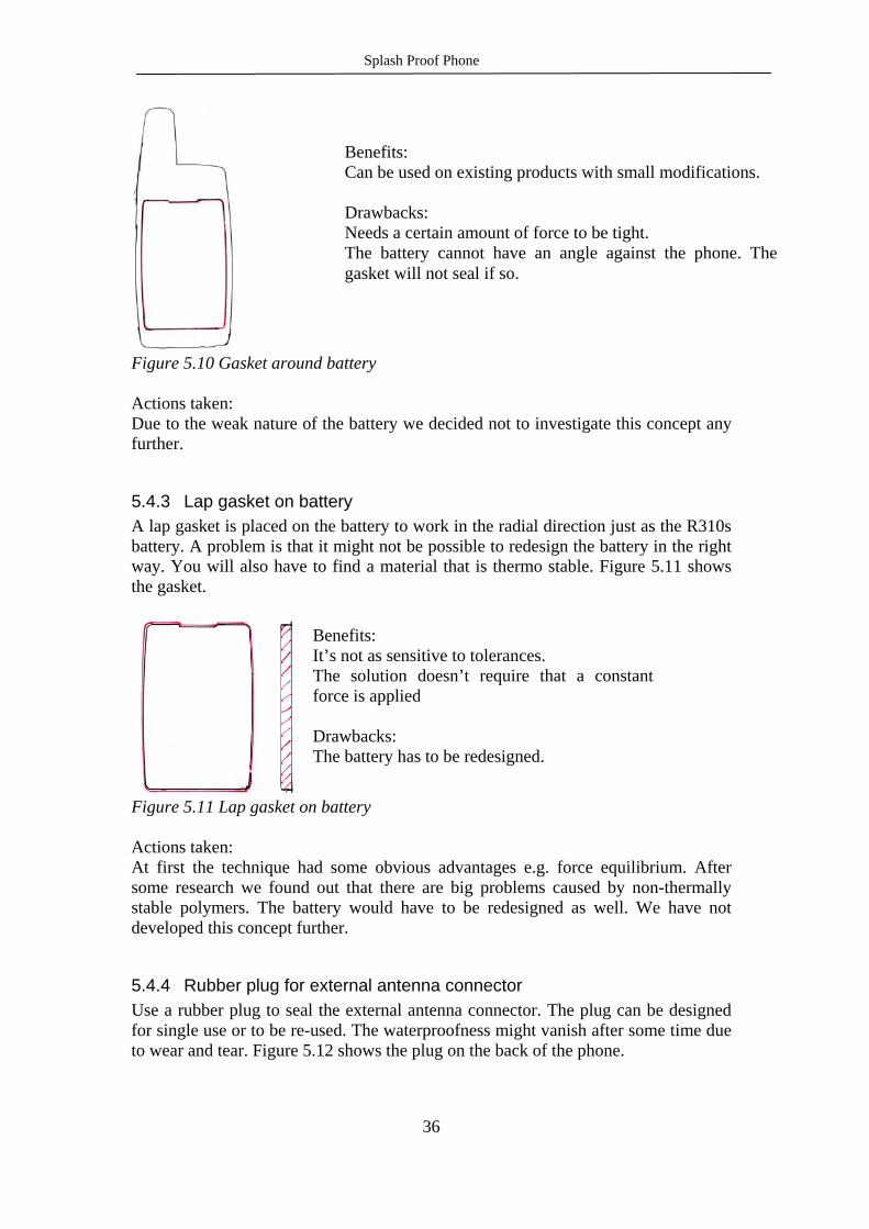
6.2 PROTOTYPES MADE BY SUPPLIERS ........................................................ 51 6.2.1 Keypads (Fremach) ....................................................................................... 51 6.2.2 Loudspeakers ................................................................................................ 51 6.2.3 Acoustic membranes ..................................................................................... 52
6.3 FEM SIMULATIONS OF THE FRONT FOIL................................................ 53
7 TESTING .................................................................................................................. 55
7.1 ACOUSTIC TESTS .......................................................................................... 55 7.2 RAIN TESTS .................................................................................................... 57
8 RESULTS .................................................................................................................. 61
8.1 RESULTS FROM THE ACOUSTIC TESTING .............................................. 61 8.1.1 W.L. Gore cloths ........................................................................................... 61 8.1.2 Hyonsoo water proof speakers ...................................................................... 65
8.2 RESULTS FROM THE RAIN TESTING ........................................................ 67 8.2.1 Acoustic cloths .............................................................................................. 67 8.2.2 Other rain tested prototypes ......................................................................... 68
9 ANALYSES AND DESIGN GUIDELINES .......................................................... 69
9.1 ACOUSTIC TEST ANALYSIS ........................................................................ 69 9.2 RAIN TEST ANALYSIS .................................................................................. 70 9.3 DESIGN GUIDELINES ................................................................................... 70
9.3.1 Materials ....................................................................................................... 71 9.3.2 Acoustical parts ............................................................................................ 71 9.3.3 Keypad .......................................................................................................... 72 9.3.4 System IO ...................................................................................................... 72 9.3.5 Battery and SIM-card ................................................................................... 72 9.3.6 Antenna ......................................................................................................... 73 9.3.7 Volume button ............................................................................................... 73 9.3.8 Frame/Front joint ......................................................................................... 73
REFERENSES ................................................................................................................ 75
APPENDIX 1. DRAWINGS FOR PROTECTIVE MEMBRANES
APPENDIX 2. HYONSOO WATERPROOF SPEAKER

Splash Proof Phone
VI

Splash Proof Phone
1
1 INTRODUCTION
1.1 PREREQUISITE This Master Thesis is performed at Ericsson Mobile Communications AB in correspondence with Department of Machine Design, Lund Institute of Technology. Ericsson Mobile Communications AB is a multinational corporation in the telecommunications industry. Ericsson Mobile Communications AB develops mobile telephones and terminals. This thesis will exclusively address development of mobile phones.
1.2 BACKGROUND “Ericsson still believes in the great idea – that communication is a basic human need for everybody. That is why Ericsson over the past 125 years has provided communication for hundreds of millions of people all over the world and still believes that it is about communication between people. The rest is technology.” The Ericsson Story, 3 October 2000 Mobile phones are products in a market with continuously increasing demands. The consumers tend to use their mobile phones in all their activities and expect them to perform in tough, like wet or dusty, environments. The Swedish National Board for Consumer Complaints receives many complaints where mobile phones are damaged by damp and they mean that mobile phones generally are sensitive for water.1 If the customer demands should be fulfilled, the durability of the phones must be increased. To face this challenge, Ericsson must find a way to design and produce products that will satisfy these higher demands.
1.3 PROBLEM The problem that makes this thesis needed is the fact that the telephones of today generally, except for the ruggedized ones, are too sensitive to water.
1.4 OBJECTIVE The primary goal of this project is to identify the problems, and possibilities, with water sealing of a mobile phone. The suitability of different techniques and materials will be examined. Both new and well-known techniques will be studied and evaluated from a sealing point of view. The solutions shall be applicable on high-volume products and are meant to be a quality improvement to upcoming phones. Other goals are to establish and adapt design guidelines for the process and to provide and test out prototypes on suitable products. The phone that will be examined and modified for testing is the Ericsson R320s. To investigate the situation and find new solutions to primarily decrease the water sensitivity this project is run as a Master Thesis at the department of Advanced Mechanics at Ericsson Mobile Communication in Lund.
1 Allmänna reklamationsnämnden in Råd&Rön 11/99, page 36

Splash Proof Phone
2
1.5 SCOPE In this thesis we, together with our superiors, have decided to concentrate on examining the R320s since it is a relatively new phone as well as it’s less expensive and easier to get samples comparing to newer phones. When it’s possible we will try to gather information about the mechanical design in future products as well. Due to time and cost aspects focus will be aimed at only a few promising ideas. These solutions will be examined further and if they turn out to be promising, prototypes will be built. During the development of the different concepts some guidelines are used as help when evaluating the solutions. The consequences for the electrical components caused by water leakage into the phone will not be examined. Since we are going to use a new specification for rain testing, new testing machinery will have to be made. This machinery will be built parallel to our project why we won’t be able to make repeatable testing until it’s finished. That will be in late December or early January. Meanwhile we will be reduced to make simple leak detection tests to get an indication of the splashproofness of our solutions.
1.6 STRUCTURE OF THE REPORT Chapter 1 explains the background and the problem that will be investigated in this thesis. The objective and scope are also explained. Chapter 2 gives the approach, i.e. the different stages of the project that has been performed. The actions of the phases are listed to give the reader a possibility to comprehend how this project is accomplished. In Chapter 3 the technical background and nomenclature are explained. The chapter gives information needed to understand the rest of the report about materials, production, testing and classification and the R320s phone. The way that some of the sealing problems, that we meet in this project as well, are solved in other products are also explained. Chapter 4 gives information about the different suppliers that we have been in contact with during this project and the techniques they use. In Chapter 5 the most promising concepts of solving all the earlier identified leakage points are listed. The different solutions are explained with figures when needed and the risks, benefits and drawbacks for all the solutions are listed. Chapter 6 gives descriptions of all the prototypes that have been built during this project. The chapter is divided into two parts where the prototypes made in house are described in one part and the prototypes made by suppliers are described in the other. In Chapter 7 the testing that has been performed is explained. All different sets of testing, acoustical and rain testing, are listed. Chapter 8 gives all the results from the testing explained in previous chapter.

Splash Proof Phone
3
In Chapter 9 the results from the testing are analyzed. The overall experience that has been gathered during this project about making a mobile phone splash proof is also summarized in what we have chosen to call design guidelines.

Splash Proof Phone
4
Splash Proof Phone
5
2 APPROACH Since this project was run as a Master Thesis some changes were made in the guidelines that are generally used for technology projects at Advanced Mechanics.2 The introduction phase has been enlarged to allow us to familiarise with the subject.
2.1 INTRODUCTION PHASE In the introduction-phase the problems of water leakage were identified. Phones of today were carefully examined and reports that explain customers’ needs and expectations were studied to ensure that the problems of the existing phones were well identified and that the target product is known. Some benchmarking was performed i.e. products on the market that are marketed to be water- or splash proof were studied.
2.2 PRE-STUDY PHASE In the pre-study phase numerous suggestions for solving the sealing of the phone were produced. A brainstorming- and evaluation group was created in order to utilise the knowledge in the company during this project. Both the possibilities to use already existing solutions and to find new solutions were examined. Both international and Ericsson’s internal standards and testing methods were studied in order to find adequate specifications and testing methods. Some testing was performed to identify the critical leaking points on the phone.
2.3 FEASIBILITY STUDY The different solutions were developed and sorted out until only a few promising solutions remained. The benefits, drawbacks and risks of the different solutions were listed and the evaluation group made, referring to these, the decision to examine the chosen solution more closely. A great deal of time and resources were spent on finding suitable suppliers and discuss the cost and possibility to produce products to our demands.
2.4 CONSTRUCTION- AND TESTING PHASE When we had decided which solutions to develop further, we started to search for suppliers with the right knowledge. At first we looked at our suppliers of today to evaluate their technical knowledge in splash proof products. After that we started to look for new suppliers with interesting techniques regarding splashproofness. In our search we found interesting companies all over the world. After initial e-mail correspondence we had meetings with some of the companies to discuss possible prototypes.
2 Guideline for Technology Projects at Advanced Mechanics

Splash Proof Phone
6
Prototypes for testing have been produced both by suppliers and by the authors of this report. The prototypes were rain tested to examine how well they fulfilled the splash proof criteria. For the acoustical parts acoustic testing was performed as well.
2.5 CONCLUSION PHASE During the conclusion phase all information, test results and knowledge that have been gathered during the project are put together. The report is finalized.

Splash Proof Phone
7
3 TECHNICAL BACKGROUND AND NOMENCLATURE
3.1 MATERIALS In the descriptions of phones and solutions many different materials are mentioned. To help the reader to fully understand the applications some of the materials characteristics are described.
3.1.1 Thermoplastics ABS – Acrylonitrile butadiene styrene is an amorphous thermoplastic with a glass-transition temperature between 100 and 120C. The butadiene rubber is located as small particles in the matrix. This gives the material its properties such as high impact resistance and enough flexibility to work in parts that are snapped togheter3. Common ABS’s are Terluran (BASF), Novodur, Lustran (Bayer), Magnum-ABS (Dow), Cycolac (GE Plastics). PC – Polycarbonate is an amorphous thermoplastic that is suitable for injection moulding. The modulus of elasticity is around 2300 MPa and the glass-temperature is around 150 C4. PC can be foiled, glued, welded and coloured in almost any colour. Common PC’s on the market are Makrolon (Bayer), Xantar (DSM), Lexan (GE), Calibre (Dow). PC/ABS – The PC’s used in front cases for mobile phones etc are often combined with ABS. This gives a material that can withstand higher temperatures and got better toughness than ABS5. Common PC/ABS’s on the market are Bayblend (Bayer), Cycoloy (GE Plastics), Pulse (Dow), StapronC (DSM). PMMA – Polymethyl methacrylate is an amorphous, hard and rigid thermoplastic that is highly transparent to light and can be readily formed by most of the forming techniques used for thermoplastic6. The widely know Plexiglass is PMMA. POM – Polyoxymethylene also known as Acetal is based on the polymerisation of formaldehyde. The material has good strength and toughness and a low coefficient of friction. The properties of the material are retained up to temperatures of 120C7. PTFE – Polytetrafluorethylene is a highly crystalline material. The carbon-fluorine covalent bond is very strong and gives a material of extreme stability. PTFE is commonly used in chemically resistant coatings, seals and gaskets and applications where the extremely low friction of the material is desirable8. ePTFE is polytetrafluorethylene that is expanded and gives the material an open structure. This
3 PlastForum Nr 7/8 1999 s45-46 4 Plaster Materialval och materialdata, 5 Plastforum Nr 7/8 1999 s47 6 Plastforum Nr 5 2000 s 67 7 Introduction to Engineering Materials, Vernon John 8 Introduction to Engineering Materials, Vernon John
Splash Proof Phone
8
open structure allows air, but not water, to pass through and is used in protective membranes to cover acoustic devices etc.
3.1.2 Elastomers Elastomers exist in numerous different qualities such as natural rubber, synthetic elastomers and thermoplastic elastomers (TPE). For this report especially polyurethanes (class U elastomers), synthetic silicone rubber (Q class elastomers) and TPE are of interest. PU – Polyurethanes are characterised by having a carbon-oxygen-nitrogen heterochain structure. They can be tailored chemically for different applications and have excellent abrasion and tear resistance. The SILICONE RUBBERS are heterochain polymers with silicone and oxygen in the chain. The [-Si-O-] unit has four valency bonds where two of the bonds link up to other [-Si-O-] units and the other two bonds link up to hydrogen or organic groups9. In phones silicone rubber are often used for gaskets and for the keypads. TPE – Thermoplastic Elastomers are materials in which elastomer phases (as soft components) are integrated in plastics (as hard components). This gives a material that has many characteristics like vulcanised rubber but is processed like plastic and does not need vulcanisation. TPE’s has today replaced rubber in many sealing applications. TPE’s are available in a wide range of qualities and can be tailor made for a specific application. The hardness varies from 5 Shore A to 65 Shore D10. TPE’s are suitable for injection moulding and are commonly used in 2K moulding. Common TPE’s on the market are: Thermolast K (Kraiburg), Hytrel (Du Pont), Dryflex (Nolato elastoteknik), Santoprene (Advanced Elastomer Systems). When we refer to TPE in this report we mean the SEBS-based TPE e.g. Thermolast K.
3.1.3 Magnesium Magnesium has a close packed hexagonal crystal structure and has a melting point at 649C. The density is 1.74x10³ kg/m3 and the Young’s modulus is 44GPa. Pure magnesium is comparatively weak but alloyed with for example aluminium, thorium, zirconium or zinc the material becomes strengthened at heat treatments. The strength/density ratio of the material then becomes attractive and the material is often used in aircraft constructions where high strength and low weight are desirable. Magnesium alloys are suitable for casting with sand or die casting methods11.
3.2 ACOUSTICS In this chapter the different parameters that are measured in the acoustic tests and some other acoustic terms are explained briefly12 13.
9 Introduction to Engineering Materials, Vernon John 10 Gummiwerk Kraiburg GmbH & Co. Product information sheet Thermolast K 11 Introduction to Engineering Materials, Vernon John 12 ETSI GSM Technical Specification, GSM 03.50 13 Mats Erixon, ECS

Splash Proof Phone
9
Loudness rating: The loudness rating is one of the standardised values that are measured to see if the acoustic system fulfils the international requirements. For the microphone the SLR (Sending Loudness Rating) is measured and for the loudspeaker the RLR (Receiver Loudness Rating) is measured. The SLR and RLR are dependent of both the hardware and the software in the object and are measured in dB. The nominal values shall be: SLR=8+/-3 dB; RLR=2+/-3 dB. Frequency response: The frequency response is also measured for both the microphone (TX/FR) and the loudspeaker (RX/FR). The response is measured for different frequencies between 100 and 4000 Hz and the response shall be within a mask which can be drawn with straight lines between the breaking points on a logarithmic (frequency [Hz]) – linear (dB sensitivity) scale, as shown in Figure 3.1.
Figure 3.1 The GSM mask Distortion: The distortion requirements describe how well the overtones are cancelled out at different sound pressures. The overtones are weighted against the fundamental tone and the requirements say how many dBs under the fundamental tone they should be. The distortion for the microphone are written TX Dist and for the loudspeaker RX Dist. Transmission loss (dB) and Acoustic impedance (Pa-s/m) are two quantities that W. L. Gore presents for their membranes. They are measured unsupported in an impedance tube with a 35-mm cross-sectional diameter. The values represent the average transmission loss and acoustic impedance over the frequency range 0.3 to 3 kHz. It isn’t possible to translate these two quantities directly to the ones measured in our acoustic tests but they can be very valuable if any simulations for the materials should be performed. The Acoustic department at Ericsson Mobile Communications in Lund has an impedance tube under construction so they, when the tube is finished, will be able to measure these quantities for different cloth materials. The function of the tube builds on the principle that incoming and the, in the tested material, reflected
0.1 0.2 0.5 1 2kHz
-30
-20
-10
0
10
20
30 dBPa/V
Upper GSM Mask
Lower GSM Mask
Frequency Response

Splash Proof Phone
10
sound waves are measured. From these data the transmission loss and acoustic impedance for the tested material at a determined application can be derived.
3.3 TESTING AND CLASSIFICATION
3.3.1 IP Coding As some of the tests in this report refer to the IP classification in the international standard IEC 6052914 parts of this standard is explained. The IP Code system is described as follows in the standard: “A coding system to indicate the degrees of protection provided by an enclosure against access to hazardous parts, ingress of solid foreign objects, ingress of water and to give additional information in connection with such protection.” The IP Code, as shown in Figure 3.2, indicates the degree of protection by an enclosure. The first characteristic numeral describes the protection against solid foreign objects. The second characteristic numeral describes the protection against ingress of water with harmful effects. The additional letter describes the meaning for the protection of persons and the last letter describes supplementary information for the protection of the equipment, such as high-voltage apparatus, weather conditions etc.
Figure 3.2 The IP Code system Figure 3.2 shows the testing equipment and method for the different protection levels. The most interesting level for this report is the IP X2 (see Table 3.1) because of it’s similarity to the testing used in this project. A drip box is used to produce the uniform flow of water drops over the whole test item. The water flow is 3 mm/min and the total test time is 10 min. The item is tested for 2.5 minutes in each of four
14 International Standard, IEC 529, “Degrees of protection provided by enclosures (IP Code)”
IP 2 3 C H Code letters *International Protection First characteristic numeral *Numerals 0 to 6, or letter X Second characteristic numeral *Numerals 0 to 8, or letter X Additional letter (optional) *Letters A, B, C, D Supplementary letter (optional) *Letters H, M, S, W

Splash Proof Phone
11
fixed positions of tilt. These positions are 15 on either side of the vertical in two mutually perpendicular planes. Table 3.1 International standard for ingress of water.
3.3.2 Definition of “Splash Proof” Splash proof in this report means that the phone is functional during and after the rain test. The rain test is performed almost like the international standard IEC 529 (class IPX2) with testing equipment working after the principle shown in Table 3.1. The water flow rate is 3 mm/min and the duration of the test is 10 minutes. Our testing method differs from IEC 529 in one way. For the IP X2 the object is tested in four fixed positions but in our test the objects will be tested in many positions. Our specification says that the phone is functional during and after the test.
3.3.3 Testing methods for water testing Generally there are two different concepts when dealing with the terms of leak testing. The terms are leak detection and leak test. To explain the difference between them they can be described with one question respectively15; Leak detection – “Where is it leaking?” and for Leak test – “How much is it leaking?”. For both types of tests there are quite exquisite methods to answer those questions such as bubble testing, sniff testing, ultrasonic, chemical trace and chemical penetration for the leak detection and different types of both absolute and differential pressure methods for the leak testing. None of the mentioned methods are really suitable to use in this project since they are developed to be used when the tested object is implied to be completely waterproof to be considered as acceptable. When dealing with non- or only partial
15 M. Gonzalez Document D/I: 00:016 Uen

Splash Proof Phone
12
sealed objects that are not dimensioned to resist any pressure, like we do in this project, it is harder to find really suitable and repeatable methods. So, when the leaks of the R320s phone where identified and later on when the different solutions should be tested, methods that where similar to the actual situation, that the phone should perform in, where used. Different types of rain tests where performed. In the early stage of the project only a simple spray nozzle were obtainable but in a later stage a drip box where used. Also coloured liquid and fluorescent liquid (Fluoresceinnatrium) were used to simplify the visual examination. To test gaskets, membranes or other partial solutions, simple methods like dripping water manually or place a small amount of water on the sealed parts were used. Since it is very hard to verify exactly where and in what amount the water has leaked into the phone the rain test can be said to be a very simple combination of both leak detection and leak testing that is interpreted subjective after functionality tests and visual examination of the tested object. The testing methods investigated in this project are only considering the development of a splash proof phone and are not to be used in production testing.
3.3.4 Testing equipment used for Splash Proof testing Since we had chosen the IP X2 standard to define Splash Proof we would have to get a device that could simulate a specified amount of rain. The IP X2 standard says that the amount of rain shall be between 3 and 3.5 mm per minute and the test object shall rotate with a speed of 1 rpm in the rain. The rain is made by putting a large number of needles in the bottom of a large container filled with water. There is one needle for each 4 cm2 and the distance between the test object and the needle is 20 cm. To a pipe that is adjustable in height adjusts the pressure in the container. See Figure 3.3

Splash Proof Phone
13
Figure 3.3 Reine
3.3.5 Testing methods and equipment used for acoustic testing The different properties that are measured in the acoustic tests are Loudness rating, Frequency response and Distortion. These properties are described in Chapter 4.2. The equipment used in the tests is located at the Acoustic department at Ericsson Mobile Communications and the measurement methods are designed to fulfil the specifications described in the GSM 03.50 standard issued by ETSI (European Telecommunications Standards Institute).
3.3.6 Functional test After the rain test we dried the phones with a cloth and made a functionality test to verify the operational mode of the phone. Our test included that a call were made and the sound quality were checked subjectively. The function of the buzzer, the vibrator and keys were also checked.
Adjustable pipe
Shower Cabin
Rotating table
Test pieces
Needles
Electric motor

Splash Proof Phone
14
3.4 PRODUCTION As the manufacturing of the parts and the assembly of the complete phone have to be considered as important aspects in mobile phone production, some factors and techniques are described to illustrate their drawbacks, benefits and possibilities.
3.4.1 Multi-component moulding To come up with details with more than one colour or with more than one material quality, the multi-component technique can be used. While Ericsson’s front covers mainly are moulded with the two component (2K) technique the principle for this process will be explained. One way of 2K moulding uses a rotating mould and multiple injection units. When the part of the first material has solidified the core and part rotate to a larger cavity where the second material is moulded over the first part16. See Figure 3.4.
Figure 3.4 2K moulding technique
3.4.2 Laser welding The technique in short works like this. A transparent material (transparent for IR, not necessarily for the visible light) is used for the upper material. The base material needs to have a high absorption level to provide heat to perform the weld. The laser transparency is altered by, in general, additives such as colouring and fillers. Most base polymers are transparent. Typical materials being used are polypropylenes, PC/ABS or polycarbonate. TPE's would need more investigation. Polymers to metals can be achieved by adding a coating to the metal surface. 16 Plastic Part Design for Injection Moulding, Robert A. Malloy
Finished 2K part
Material 1 2K mould
Material 2 Rotating core
Injection unit 1
Injection unit 2

Splash Proof Phone
15
Passing a laser through a sample of the material and measuring the output can confirm material suitability. Materials for the upper and base can vary in melting temperature (up to 60C difference had been successfully welded). However, similar materials are preferable. Material thickness can vary between 0.06 up to 3mm and above. Since continuous welds are inherently waterproof they are very interesting from a water sealing point of view. Laser welding is also non-contact, clean, and does not produce surplus material, which is a good property. Surface interface thickness is negligible and does not add to the assembly height. Interface design requires no specific features other than surfaces should be in contact to ensure thermal conduction. This is achieved by clamping the parts whilst welding.
Figure 3.5 Laser welding
3.4.3 Assembly When constructing parts in a phone one always has to think about how to assemble the parts in an automatic way. The R320s is constructed for Z-direction assembly, which means that all internal parts are mounted on top of the frame with screws by robots and later on snapped into the front, see Figure 3.6. There are subassemblies made on carrier, front and PCB. The receiver and the LCD are attached with an adhesive tape into the carrier. There is a problem with rubber on the outside of the phones. It’s easily scratched in the automatic assembly process, which affects the yield negatively. Another problem with ruggedized phones are gaskets that have to be placed in the right place. It’s easier, in an assembly point of view, to use gaskets that are glued on the part like the silicone gasket in the R310s.
>0.05mm
Transparent
Low
Weld
Diode laser array
MaskCla
Laser / work piece Depends on spot size required

Splash Proof Phone
16
3.5 THE “ERICSSON R320s” PHONE
3.5.1 Structure The R320s is a pocket phone without flip. It consists of more or less seven major parts: frame, PCB, carrier, key-tree, front, volume button and antenna. The carrier, PCB and the frame are held together with seven screws. The front is snapped onto the frame. See Figure 3.6.
Figure 3.6 R320s assembly The R320s has a 2K (two-component) front in PC+PC/ABS that is snapped onto the frame. The front assembly consists of buzzer gasket, speaker cloth, window and a volume button. See Figure 3.7. Volume button: This button is placed on the side of the phone. By sliding it up or down you can control volume or get telephone status. The material is Acetal. See Figure 3.7. Buzzer gasket and Speaker cloth: These two parts are in the front to prevent dirt and sharp objects to get into the phone. They have no big influence on the acoustical parameters. See Figure 3.7. Window: The window is made of PMMA and it is glued into the front. See Figure 3.7.
Front
Antenna
Carrier
PCB
Key-tree
Frame

Splash Proof Phone
17
Figure 3.7 The Front Key-tree: The key material is PC and the keys are held together with small branches, this is why it’s called a tree. See Figure 3.8.
Figure 3.8 Keytree, front and back Carrier: The carrier is a thermoplastic, PPS part that holds the loudspeaker and LCD together and is mounted with screws on the PCB. Receiver: This is what we normally would call an earpiece. The R320s has got a 15mm receiver that uses the volume inside the phone to get better frequency response for the lower frequencies.
Figure 3.9 Carrier assembly
Buzzer Speaker cloth
Mic
Volume button
LCD
Receiver

Splash Proof Phone
18
PCB: All electrical components are mounted on the PCB (Printed Circuit Board). You could say that the PCB with its components is actually the phone. The rest is just for cover and to facilitate the interface. See Figure 3.10. System IO: This connector is used for charging the battery in the phone as well as connecting different accessories. See Figure 3.10. Microphone: R320s has got a 2.7mm microphone with noise cancelling which implies that it get sound from both the front and the frame. See Figure 3.10. SIM-card reader: This is a slot were you insert a SIM (Subscriber Identity Module) card. It is placed under the battery. See Figure 3.10. Battery connector: There are five pogo pins that connect the battery to the PCB. See Figure 3.10.
Figure 3.10 PCB assembly Frame: This is the piece that the PCB and the carrier in the phone are mounted onto. On the R320s it is made out of a magnesium alloy. See Figure 3.11.
Figure 3.11 Frame
SIM card reader
Battery connector
Mic tube
System IO
Dome
Rear antenna
Vibrator

Splash Proof Phone
19
Antenna: There are a lot of different materials in the antenna due to different properties e.g. conductivity, shielding and wear resistance. The antenna is snapped onto the phone. See Figure 3.12.
Figure 3.12 Antenna
3.5.2 Identified leaks This whole master thesis is about making the R320s splash proof. To achieve this goal we had to seal all possible leaks. At first we thought that the whole problem was to find different solutions of gaskets and sealing. As we started to work we realised that it was just as hard to find the leaks. It’s not difficult to decide whether it leaks or not but it’s difficult to see exact were the water is getting in to the phone. We found out that more or less every possible joint in the phone was leaking. The leak points that we found were: -Volume button -Keypad -Battery connectors -SIM-card reader -Antenna (including the external antenna connector) -Joint between the frame and the front -Loudspeaker -Microphone -Buzzer -System IO The different points of leakage will not have the same priority during this project due to the limitations in time, budget and possibility to try the solution on the R320s telephone.

Splash Proof Phone
20
Figure 3.13 Identified leaks
3.5.3 Hazards with water leaking What happens if water leaks into the phone? To do a complete analysis of what happens when water gets into the phone and come in contact with the components inside would be a way too extensive task to do in a Masters Thesis. Sure is that phones of today (like other electrical equipment) take harm of water and moisture. There is a risk for all the surface mounted components on the PCB as well as for the display, loudspeaker, buzzer, microphone, system I/O, vibrator and more. The components might be short-circuited immediately or the moisture might react with the materials and form conductive oxides over time.
3.6 SEALINGS IN RUGGEDIZED APPLICATIONS A watertight construction is desirable in many applications when the item is supposed to be used in all weather conditions. Examples of products on the market that are water protected are cameras, mobile phones, watches, torches, connectors, binoculars, GPS-navigators etc. The products examined more closely are the splash proof phones available on the market during the performance of this thesis. The solutions of some critical points for the different phones are listed in Table 3.2. The Ericsson R250PRO was the first so called ruggedized phone available on the market. Ericsson R310s is a smaller phone built on the 3V platform. Both these Ericsson models are very well protected and the requirements of these phones are much tougher than the ones on our “splash proof phone”. The Siemens and Nokia phones are commercialised as tough and water protected. The Casio IDO phone is only available on the Japanese market and should be water protected as well. See Table 3.2.
Battery connector
SIM card reader
Receiver
Buzzer
Microphone
Keypad
Rear antenna

Splash Proof Phone
21
Table 3.2 Sealings in similar applications
Ericsson R250Pro
Ericsson R310s
Siemens M35
Nokia 6250
Casio IDO
Acoustic parts Loudspeaker Microphone Buzzer
Waterproof ePTFE (W.L.Gore) membrane and trapped air ePTFE (W.L.Gore) membrane
Waterproof EPTFE (W.L.Gore) membrane ePTFE (W.L.Gore) membrane
Air canals and dustcloth Waterprotected membrane Waterprotected membrane
Waterprotected membrane Waterprotected membrane Waterprotected membrane
Waterprotected membrane Waterprotected membrane Waterprotected membrane
Keypad
Silicone keypad pressed to the front
Silicone keypad pressed to the front (Replaceable)
Silicone keypad pressed to the front (Replaceable)
Silicone keypad with plastic frame glued to the front
Hardtops on TPE-mat moulded to the front
Display
Ultrasonic welded
Adhesive Axial rubber sealing
Glued -
Battery
Radial silicone gasket
Radial silicone gasket
Radial and axial rubber sealing
Axial silicone gasket
Silicone gasket around the Contacts
Antenna
O-ring/ Rubber plug
Sealed connector
Built in / Rubber plug
Built in / Rubber plug
O-ring / -
Front/Backside
Silicone gasket Silicone moulded to the frame
Silicone gasket Silicone gasket -
System I/O
Sealed connector
Sealed connector
Rubber plug and sealed connector
Sealed connector
O-ring

Splash Proof Phone
22

Splash Proof Phone
23
4 SUPPLIERS AND THEIR TECHNIQUES In this chapter the most interesting suppliers that we have been in contact with and their techniques or materials are presented. The contact with the companies have been via e-mail, telephone and in most cases also meetings.
4.1 FREMACH Today Fremach is the supplier for the keytree in R320s, T28s and the R520m. Earlier we had taken standard keytrees, cut the keys apart and moulded them into a mat of silicone. This proved to work satisfying but the repeatability wasn’t good. This is why we wanted Fremach to do the same but in a production application. After some initial correspondence we had a meeting in Lund to discuss the case. Fremach had then started a group that were looking at splash proof keypads. Their suggestion to seal the R320s keypad was to cut the keys loose from the tree and then make a mould and inject TPE around the keys. This was more or less the same solution as we came up with. Their material specialists had made quite successful test with adhesion between PC-TPE. Later on when Fremach had been contacting their suppliers they suggested that we should go for Poly-Urethane (PU) instead. PU and PC have very good adhesion as well as it is very suitable for 2K moulding. Their final proposal to make fast prototypes was as followed 3D modeling of the sealing Stereo lithographic model of the sealing Vacuum casted mould to make the prototypes in (made with STL model) Prototypes of the keypad with sealing, moulded (15x) The sealing of the prototypes will be produced in Poly-Urethane. The keys will be standard Poly-Carbonate keys as used for current production.
4.2 HYONSOO In the beginning of our project we came up with a solution to use a 15mm speaker with a membrane that could withstand water. The idea isn’t new but there were only bigger loudspeakers on the market. After a while we came in contact with the Hyonsoo, a company that is developing a 15mm waterproof receiver. Hyonsoo is a small Korean based company that has specialized in making speaker drivers and speaker systems for the computer and car industry. The company has about 45 employees and the sales turnover was US$ 3.5 billions for the year 2000. After a meeting with the Ericsson team in Bilbao we got some Hyonsoo samples from them to mount into the R320s. We were in contact directly with Hyonsoo as well. They were very obliging and sent us samples. Since these samples were built for another project they didn’t fulfill the GSM specification when mounted into the R320s. To get a new design we sent them a few samples of the current R320s speaker manufactured by Kirk. Hyonsoo redesigned the water proof receiver so that it would fit into the R320s both physically and acoustically. The new test results proved to be very promising. We didn’t test the receivers according to the whole

Splash Proof Phone
24
GSM specification since we’re primary interested in its mechanical properties. There is no reason to test the receiver further since it will get new properties if designed into a new phone concept.
4.3 GUMMIWERK KRAIBURG Gummiwerk Kraiburg is a German supplier that mainly manufactures rubbers in all different qualities. We first came in contact with Kraiburg via their Swedish general agent Rodlin Kemi in Gothenburgh. The meeting we had with Kraiburg mostly was about what materials they can provide Ericsson with for applications such as different types of inmould keypads and sealings in the front. Kraiburg’s TPE Thermolast K is an interesting alternative for this type of applications because of the wide range of different qualities. The Thermolast K is a SEBS-based TPE, which has rubber-like characteristics, very good low temperature flexibility, high thermostability, electrical insulation and good resistance to UV, ozone, weathering and hydrolysis. The materials can be tailor-made to meet the application requirements. Characteristics that can be optimised are the hardness (5-90 Shore A), transparency and colouring. The most transparent qualities have the best adhesion to Polypropylene and Polyethylene but if the transparency is lower the adhesion to PC/ABS is good as well. The easy processability and due to short injection times Thermolast K are suitable for injection moulding as well as for extrusion or blow moulding. Kraiburg delivers material to other customers that use it in 2K applications e.g. to mould in the keypad in the phone front. The figures on the buttons can be printed, inmoulded or done with laser. The samples made with this technique had soft buttons and the “click-feeling” did not come from a dome but from the design of the moulded keypad (like in the older Ericsson silicone keypads). Kraiburg’s technicians mean that this solution works very well. The sealing of the keypad won’t be any problem while it is a completely sealed solution but the question is if the solution satisfies the demands wanted in button feeling and transparency. While the material is very suitable for 2K moulding it definitely is an interesting alternative for any gaskets or if hardtop keys should be inmoulded.
4.4 NOLATO SILIKONTEKNIK Nolato Silikonteknik AB is a part of the business area Mobile Communication within Nolato. The information given is collected from Jan Erik Lans, Managing Director and Sakari Muhonen, Project Manager from Nolato Silikonteknik AB. What we are interested in is Nolato’s experience in silicone rubber and their moulding techniques. One example of a part they can deliver is the overmoulded environmental and EMS silicone gasket on the R310s frame. This technique reduces the number of parts and improves the assembly of the phone. Another example is the overmoulded battery cover with a radial environmental gasket to the R310s. The discussions we’ve had with Nolato mainly were about the possibility to manufacture prototypes of the R320s front with inmould keypad, display gasket and

Splash Proof Phone
25
environmental gasket of silicone. Nolato recommend trying keypad of solid silicone that is moulded in the front. The problem we meet is that the PC material (Makrolon 2405) in the front and the window material (PMMA) probably will be deformed when they are exposed for the combination of the high mould temperature and pressures that occur at silicone moulding. The important adhesion between the silicone and the Makrolon 2405 will probably not work properly either. Regarding the sealing between the front and the frame it was stated at the meeting that there is no space to mould a silicone gasket on the front if it should be assembled on a standard frame. The mechanical design is simply too tight to fit in a sealing. When designing a new phone however there shouldn’t be any problem to design in a solution like this. To seal the battery we don’t see any really good solution using Nolato’s techniques with today’s design of the phone. With some changes in the design it is possible both with a radial sealing as well as with an axial sealing. Nolato means that the radial sealing is to prefer because of the fact that the forces work radial in the construction. If the parts aren’t rigid enough and the sealing works axial it can create a gap in the phone. Because of the combination of the cost to manufacture new moulds, the limited possibilities to apply the technique on the front of today’s design and the problem of using the front materials there won’t be any prototypes built. However Nolato has a test mould under development, where they are trying to implement inmould silicone solutions such as keypad, environmental gasket and dust gasket. When this is finished it should be of interest for Ericsson to examine the property of the solution.
4.5 TAISEI PLAS The company Taiseiplas in Japan uses a technique where they mould in buttons in the front with TPE. We have received samples and we have closely discussed their technique at a meeting with Masanori Naritomi, President and Kogori Osumi, Sales Department from Taiseiplas. The buttons are made of foil / hard plastic. The manufacturing of a front with this type of inmould buttons needs four moulds: Mould to inject the front Mould to press the film to keys Mould to inject PC to the keys Mould to inject the TPE The key film is printed on the backside, placed and formed in another mould and then the PC is injected and the film is laser-cut to a key tree. The key tree is then placed in the front and the TPE is overmoulded. For prototypes, using an existing front can reduce the cost while only three moulds are needed. This is the technique used in the Casio Ido phone and we think it’s a very interesting solution for Ericsson as well. The samples provided from Taiseiplas shows that the fronts made with this technique have very high finish, the buttons are well centred

Splash Proof Phone
26
and the button feeling is good. According to Taiseiplas a front with keys moulded in like this is waterproof approximately 1 million button depressions. The possibility to manufacture prototypes on a R320s has been discussed closely with Taiseiplas. Taiseiplas has been provided with files of the data needed to produce a series of approximately 50 parts. It is possible to make prototypes but unfortunately the cost is too high to fit in this projects’ budget.
4.6 TOKIN CORPORATION To investigate the possibilities with multi-mode actuators we have been in contact with Koji Takahashi, General Manager MA Division, Detlef Prins, Sales Manager and Tohio Kuriya, Managing Director from Tokin Corporation. Instead of using loudspeaker, vibrator and buzzer it is possible to use a so-called multi-mode actuator. This device can perform receiver mode, buzzer mode, vibrator mode and loudspeaker mode. Tokin manufactures some actuators that can be of interest in this project. The Tokin “11-series” is of interest because of the possibility to design a telephone waterproof using this device. The Type11N actuator is mounted on the inside of the phones front cover and doesn’t need any holes. The enclosure is designed with an area of suitable thickness and size and this area is used as a vibrating zone (diaphragm). The actuator is mounted to the front enclosure with adhesive tape and two guide pins. Figure 4.1 shows schematic enclosure design.
Figure 4.1 Schematic enclosure design and multi-mode device mounting. The Type 11G actuator need holes in the front cover but is enclosed to withstand the water. The actuator is fastened to the front with adhesive tape that stops the water to reach further into the phone.
Front enclosure
Multi-mode actuator
Adhesive tape

Splash Proof Phone
27
4.7 W.L. GORE Gore have been involved in all ruggedized projects within Ericsson as they have a lot of knowledge about membranes for the acoustical parts of the phone. After we had met them at a component fair in Gothenburg and discussed the problem they came to Lund to demonstrate their techniques and to introduce the different materials. The materials used for the R250PRO and the R310s were all meant to stop all water or moist to get into the phone. Our specifications were not that strict, therefore we could use other materials that would suit us better. On a meeting with Gore specialists from the U.S. we discussed what material that would fulfil our specifications and how they should be mounted on the phone. The biggest problem in getting the membranes into the R320s was to get a satisfying thickness and width of the adhesive. Our next action was to make drawings of the membranes that we wanted to be prototyped and send them to Gore U.S. W.L. Gore produces numerous types of different membranes and gaskets. The materials that will be of interest in this report are the ones used for protection of acoustic devices. The membranes made of ePTFE are generally a better barrier against liquids than the nonwoven materials but have a larger transmission loss. The use of protective membranes together with noise-cancelling microphones may also have a wanted effect of reducing the effects of transient noise sources such as wind and normal speech. While this is an obvious problem of the R320s of today’s design it will be of interest to test the acoustic effects with protective membranes. Some material properties for different Gore-materials are shown in Table 4.117. Note that not all materials available are presented in the table.
17 W. L. Gore & Associates, Inc. Information chart 2042, 2043, 2044, 2045 9/00

Splash Proof Phone
28
Table 4.1 Gore material properties Material name
GAW101 GAW102 GAW201 GAW205 GAW301
Material type Nonwoven Nonwoven ePTFE Laminate
ePTFE Laminate
ePTFE Membrane
Transmission Loss (dB)
< 0.5
<1
-
-
<2
Acoustic Impedance (Pa*s/m)
55
75
200
-
100
Water Protection
Drip
Splash
-
14 m of water
8 m of water
Thickness (mm)
0.15
0.35
0.13
0.39
0.02
Applications Dust and splash protection for speakers, microphones and alerts.
Dust and splash protection for speakers, microphones and alerts.
Resistive element for acoustic transducers. Shape up the performance of noise-cancelling microphones.
Vents for pressure and battery venting.
Protective covers for ruggedized protection for speakers, microphones and alerts.

Splash Proof Phone
29
5 CONCEPTUAL DESIGNS
5.1 SPECIFICATIONS There is one primary requirement for the solutions in this project; the splash proof criteria. The metrics are described in 4.3.2. If the phone should be able to fulfil these specifications it leads to that all the partial solutions also fulfil them. It is very hard to speculate in how well the solutions will be able to stand up to these primary requirements. Until the solutions are tested it is not possible to se if the criteria are fulfilled. To have some help in the earlier stages in the project to sort out the most promising solutions a few secondary requirements, guidelines, are established. They are used during the investigation of the different concepts to see if they are suitable in a mobile phone application. It is important to make clear that these requirements are just used as a help and that it is the evaluation group that makes the finally decisions. All the requirements are not valid for all the ideas. To avoid tests the secondary requirements are measured subjective after information about the idea is collected by brochures, books and the web or by discussion with suppliers and specialists. Some of the different guidelines that have been used are: Durability (wear resistance, corrosiveness etc.), Mechanical Design (replaceable part, weight, size, design, number of parts etc.), Production (z-axis assembly, production time etc), Supplier (availability etc), and Degree of innovation.
5.2 VOLUME BUTTON
5.2.1 Gasket on existing button Modify the volume button so that it seals against the existing front. Mould in a sealing (rubber, silicone rubber, TPE) around the button that seals against the front. The risks are wear out and that the friction between the sealing and the front might be too high. There is also a risk that the material loses its elasticity after some time. Figure 5.1 shows the modified button.
Figure 5.1 Inmould sealing. Actions taken: No prototypes have been made due to expensive tools.
Benefits: Sealing function independent of the button position. Drawbacks: 2K moulding of the button
Inmould sealing
Phone front

Splash Proof Phone
30
5.2.2 Sealing between button and front Use the existing button and apply a sealing between the button and the front. The sealing might be in PTFE or similar because of the low friction and the high water resistance of the material. The risks are that the sealing will roll and break when used and that the sealing function is unsafe. Figure 5.2 shows the gasket between button and front.
Figure 5.2 Sealing between button and front Actions taken: Some fronts have been modified to fit in the sealing. Different types of materials have been tried for the gasket. See chapter 6.1.6.
5.2.3 Rubber gasket between button and front A rubber gasket is attached between the front and the button and is stretched when the button is used. The risks are that there will be too high friction between button and rubber and that it is difficult to attach the rubber to the front. Figure 5.3 shows the rubber gasket.
Figure 5.3 Rubber gasket Actions taken: There isn’t space enough to fit in the gasket so no prototypes have been built.
5.3 KEYPAD
5.3.1 Protective surface on the dome-plate
The dome-plate is charged with a protective layer of Parylen, silicone rubber or similar material. The water is then allowed to pass the keypad and reach the dome-plate. The dome-plate must be sealed against the front. The risks with the coating are that it is hard to achieve the wanted button feeling and that there might be too large
Benefits: The existing button may be used. Drawbacks: Difficult assembly.
Rubber sealing
Benefits: The existing button can be used. Sealing function independent of the button position. Drawbacks: Difficult assembly.
Gasket

Splash Proof Phone
31
deformation on the coating. Figure 5.4 shows the water resistant coating of the dome-plate.
Figure 5.4 Sealed dome-foil Benefits: The technique can be used with any type of keypad. Drawbacks: The dome-plate must be sealed towards the front. Actions taken: Due to the problems to seal the PCB against the rest of the phone no prototypes have been built.
5.3.2 Inmould keypad All buttons in the front are inmould like the volume buttons on the R310s model. Termolast K (Kraiburg) or similar TPE can be used. The risk with this solution is that it might be hard to find a material that satisfies the demands wanted in button feeling and the backlight translucency. Figure 5.5 shows an inmould button.
Figure 5.5 Inmould keypad Actions taken: No prototypes have been manufactured due to the high cost of the tools.
5.3.3 Inmould hardtops
If the hardtop feeling of the keys is wanted it is possible to mould in a keytree or a hardtop keypad made of foil and plastic. The keytree is then placed in the front and the elastomer is moulded on see Figure 5.6. The material used for sealing can be silicone or TPE. The click-feeling in the buttons are preferably achieved with domes on the PCB.
Benefits: Documented reliable sealing effect. No needs for other gaskets, screws or adhesive at the assembly. Drawbacks: 2K or 3K moulding Splash Proof Phone e performed.
Inmould button
Phone front
Adhesive PCB
Coating
Foil with domes

Splash Proof Phone
32
Figure 5.6 Inmould hardtops Actions taken: Close discussions have been had with the Japanese company Taiseiplas regarding their technique and their possibility to make prototypes. Unfortunately the cost is too high to fit in this projects budget.
5.3.4 Key-tree with silicone Like the solution on the R310s telephone. The principle is shown in Figure 5.7. The outer edge of the silicone keypad seals in a slot in the front. A PC key tree is used to lead the force to the domes. This solution also needs a carrier (not shown in the picture) to support the keypad to obtain the needed force between front and silicone. The risk with this solution is that the soft touch feeling you get from this type of silicon keypads is not always wanted.
Figure 5.7 Silicone rubber key pad Actions taken: We have discussed this solution with the R310s team. The experiences from the development of the R310s model are that this solution works well. The keys will lose the hardtop feeling with this solution. It’s also very hard and costly to modify a R320s front in a way that this solution could be applicable therefore there won’t be any prototypes built.
5.3.5 Unattached hardtop keypad A combination of the inmould hardtop keypad and the silicone with keytree is to mould in hardtop keys in a flexible material and then place this keypad in the front. To achieve the wanted sealing effect some force that holds the keypad against the
Benefits: Good sealing effect. Drawbacks: Takes much space. Dependent on a force that deforms the sealing. Loose the hardtop feeling
Key tree Dome
SiliconPhone front
Benefits: Completely waterproof solution. No needs for other gaskets, screws or adhesive at the assembly of the keypad. Drawbacks: It’s not possible to change keypad without changing the front.
Bonded button
Front TPE
Dome

Splash Proof Phone
33
front is needed. The front should preferably be levelled on the inside and the best alternative needs a slot in the front (like in the silicone with keytree solution) where the keypad seals against the front. Benefits: The front and the keypad are separate parts. A sealed keypad with hardtop keys is achieved. Drawbacks: The keypad needs a 2K mould to be manufactured. Actions taken: Different suitable materials have been examined. For testing purpose we have made this type of keypad with PC-buttons and silicone rubber as sealing material. See Chapter 6.1.1. Company Fremach has manufactured keypads made of PC-buttons and PU as sealing material. See chapter 6.2.1.
5.3.6 Gore material under key-tree A Gore membrane is placed under the key-tree or around each button and fastened to the telephone front. This solution has been discussed with technicians from W. L. Gore and they think it might be possible though there will be problems to attach the membrane both to the front and to the buttons. The relatively high risks that this solution complicates the assembly too much and that the mechanical load on the membrane is to large ended up in the decision that no prototypes will be built. Benefits: Large ventilation area. Any type of keys can be used. Drawbacks: Hard to fasten the membrane. Mechanical load on the membrane.
5.3.7 Front foil A foil (like the one used on the R520m front) seals the whole front. The foil consists of two laminated foils with the colour printing in between. The foil is attached to the front in the same manner as it is inmoulded in the R520m front but there are no holes in the foil for the buttons. Instead the foil flexes when the button is pressed down. The distance the button needs to flex in z-direction is about 0.4 mm. There is a risk that the fatigue strength of the foil isn’t enough and cracks will appear in the foil.

Splash Proof Phone
34
Figure 5.8 Front foil Actions taken: The technique has been discussed with the R520m team. Some FEM-calculations have been performed to investigate if the plastic has fatigue strength enough and how big the force needs to be to press down the button. See Chapter 6.3.
5.3.8 Touch sensitive buttons Use touch sensitive buttons instead of keys that are mechanically activated. Techniques that could be used are infrared light (like the proximity sensor in R520m), inductive sensors or capacitive sensors. Contact has been made with different suppliers of this type of techniques but no one have been able to recommend any suitable devices for this type of application. The drawbacks are large and it is a too extensive task to build a prototype. Benefits: No needs for holes in the front Drawbacks: Needs much space. The infrared technique needs both transmitters and receivers. The inductive technique consumes much power and senses only metal. The capacitive technique senses water etc.
5.3.9 Keypad laser welded into the front With this technique the keypad is welded to the front with laser. Suitable keypads are the TPE-pads with hard tops. One of the two materials (pad/front) needs to be transparent for IR. One of the problems with this technique is to find materials that allow laser welding. There is also a problem with different colours, some colours are laser transparent, others not. Benefits: Completely sealed keypad. No need for 2K moulding. Drawbacks: Needs to introduce laser welding in the production.
Benefits: The figures on the keys can be printed in the foil together with the other printing. Completely waterproof solution. Drawbacks: The experiences show difficulties to get the tolerances of the printing good enough.

Splash Proof Phone
35
Actions taken: We have been in contact with Richard Bowsher (EML) who has investigated this new technique. (00_0043_A.doc, 00_0046_A.doc). Since this technique is investigated in another project we have decided not to do any further research in the subject although the technique looks promising for the future.
5.4 BATTERY, SIM-CARD AND ANTENNA
5.4.1 Battery release catch This is a catch that will not interfere with the gasket since it overlaps the battery. The catch will only apply a force in the z-direction. The problem is that you have to redesign all batteries and the catch might not be durable enough. Figure 5.9 shows the redesigned battery catch.
Figure 5.9 Battery release catch Actions taken: Due to economical reasons, caused by the redesign of the battery, and lack of time we decided not to develop this concept further.
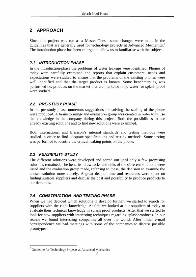
5.4.2 Gasket around battery This is a gasket that will seal between the frame and the battery in z-direction. The gasket is applied on the frame. The risk is that the catch will break caused by the gasket pressure. It might be a problem if the battery is bent, if so it will not seal against the gasket. Figure 5.10 shows the extension of the gasket.
Benefits: The catch doesn’t have an influence on the gasket. Drawbacks: The battery must be redesigned.
Battery catch
Splash Proof Phone
36
Figure 5.10 Gasket around battery Actions taken: Due to the weak nature of the battery we decided not to investigate this concept any further.
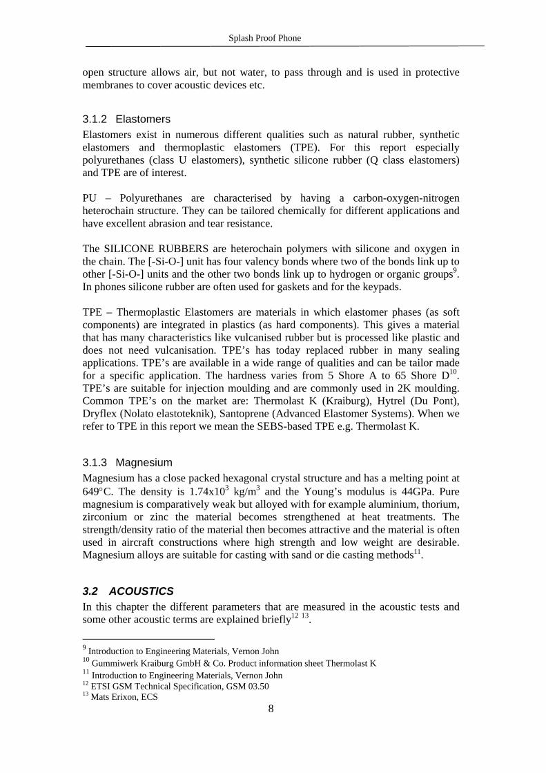
5.4.3 Lap gasket on battery A lap gasket is placed on the battery to work in the radial direction just as the R310s battery. A problem is that it might not be possible to redesign the battery in the right way. You will also have to find a material that is thermo stable. Figure 5.11 shows the gasket.
Figure 5.11 Lap gasket on battery Actions taken: At first the technique had some obvious advantages e.g. force equilibrium. After some research we found out that there are big problems caused by non-thermally stable polymers. The battery would have to be redesigned as well. We have not developed this concept further.
5.4.4 Rubber plug for external antenna connector Use a rubber plug to seal the external antenna connector. The plug can be designed for single use or to be re-used. The waterproofness might vanish after some time due to wear and tear. Figure 5.12 shows the plug on the back of the phone.
Benefits: Can be used on existing products with small modifications. Drawbacks: Needs a certain amount of force to be tight. The battery cannot have an angle against the phone. The gasket will not seal if so.
Benefits: It’s not as sensitive to tolerances. The solution doesn’t require that a constant force is applied Drawbacks: The battery has to be redesigned.

Splash Proof Phone
37
Figure 5.12 Rubber plug for external antenna connector Actions taken: We made some prototype plugs in silicone, see Chapter 6.1.4.
5.4.5 Antenna gasket and rear connector plug in one This is a variant of the R250PRO solution. The rear antenna connection and the antenna are sealed with the same gasket. A risk with the solution might be that it is not possible to find a rubber strong enough for both gasket and plug. Figure 5.13 show the principle of the solution.
Figure 5.13 Antenna gasket and rear connector plug in one Actions taken: To make prototypes we would have to get a tool made. That is expensive; therefore we decided to cancel this concept.
5.4.6 Battery-PCB cord connection Instead of pogo pins use two cords and a waterproof connection. Risks with this solution are that the cords will break or there aren’t enough room for the cords. Figure 5.14 shows the principle of the solution.
Benefits: You solve two problems with one solution. There is no risk of loosing the plug. Drawbacks: The telephone has to be redesigned. The solution is visible from the outside.
Benefits: Simple construction. Drawbacks: It might be difficult to remove the plug if threads aren’t used The plug can be lost.

Splash Proof Phone
38
Figure 5.14 Battery-PCB cord connection. Actions taken: We cancelled the concept due to lack of space.
5.4.7 O-rings O-rings are placed around the connectors for battery and SIM. A hazard is the fitting it might not be tight enough. Figure 5.15 shows the placement of the gaskets.
Figure 5.15 O-rings Actions taken: We have made a mould to make gaskets for the battery connector. For the SIM-card reader we have made a silicone film that covers the slot. See Chapter 6.1.2 and 6.1.3.
5.5 JOINT FRAME/FRONT
5.5.1 Gasket in between A gasket is placed in z-direction between the frame and the front as shown in Figure 5.16. The sealing can either be moulded on the frame, in mould with the front or be set in place as a part at the assembly. The risk with this design is that it might be tough to get the sealing functional when the phone is designed the way it is today with sharp edges and snap assembly.
Benefits: Well-known technology. It’s easy to mount O-rings. Cheap and easy to replace if damaged. Drawbacks: Difficulties with fitting. Requires a constant force from the catch.
Benefits: It’s an easy way to get around the tolerance problem. Drawbacks: It doesn’t seal the SIM-card reader. Takes space.
Battery

Splash Proof Phone
39
Figure 5.16 Gasket between front and frame Actions taken: We have had discussions with Nolato to prototype a gasket like this. The conclusions from these meetings have been that the front has to be modified to fit on the original frame to allow space enough for a gasket. Due to lack of space, high costs to modify the front and the cost related to a mould for the gasket there where no prototypes built.
5.5.2 Radial gasket Figure 5.17 shows the principle of the solution. The sealing is placed between the front and the frame in a way where the sealing works in the radial direction. The front can be attached to the frame with screws and therefore it is easy to achieve enough force on the gasket. The solution is similar to the one used in R320 Titan. While the gasket is dependent on a constant force to be functional it might be hard to find a design that seals along the whole extension of the gasket (in corners etc).
Figure 5.17 Radial gasket
5.6 LOUDSPEAKER
5.6.1 Water-resistant loudspeaker Use a loudspeaker with a water-resistant diaphragm. We want to have a 15 mm loudspeaker. Formerly the problem has been to make such a small loudspeaker waterproof and still manage to fulfil the GSM demands.
Benefits: Radial sealing Drawbacks: Tough to get the sealing functional at the sharp edges. A separate gasket makes the assembly more difficult. If screws are used the assembly becomes more difficult and time-consuming. The solution doesn’t solve the problems at the antenna and the system IO.
Phone front
Gasket
Frame
Benefits: If the gasket is made of silicone it can be moulded on the frame. It is easy to make a prototype with silicone sealing. Drawbacks: A separate gasket makes the assembly more difficult. The solution doesn’t solve the problems at the antenna and the system IO.
Gasket
Frame
Front

Splash Proof Phone
40
Benefits: You don’t have to use e.g. a Gore material to keep the water away. It’s just one unit to mount. Drawbacks: Difficulties with lower frequencies. Actions taken: We have received 15mm prototypes from Hyonsoo Corporation, which we have built into the phone and tested. See Chapter 6.2.2 for prototypes and Chapter 7.1 for the acoustic testing of the loudspeaker.
5.6.2 Gore membrane Put a Gore membrane in front of the loudspeaker. Earlier Gore has had a problem to get this type of membranes functional because of the big size. There has also been a problem with the colour, but now they can make the membranes black as well. There might be problem with the mechanical durability of the membranes. Benefits: Gore materials won’t let the water in but it will let moist go out. Possible to use different types of loudspeakers. Drawbacks: It’s difficult to get membrane in the right position, so that you don’t stop the sound The diaphragm has to be tuned in for both the loudspeaker and the whole phone. Actions taken: Prototypes have been made, see Chapter 6.2.3, and tested, see Chapter 7.1.
5.6.3 Multi-mode actuators Instead of using loudspeaker, vibrator and buzzer it is possible to use a so-called multi-mode actuator. This device can perform receiver mode, buzzer mode, vibrator mode and loudspeaker mode. The actuators that can be of interest in this project are the types that are waterproof. Benefits: One device replaces tree others. No need of Gore-membranes etc. to get a solution that is water protected. Drawbacks: Possibility of excessive sound levels when the buzzer and receiver mode can be combined. Actions taken: We have been in contacts with the acoustic department at Ericsson and with a supplier of actuators named Tokin to see if there are any suitable multi-modes

Splash Proof Phone
41
actuators. The acoustic department are writing a report concerning these devices so the technique hasn’t been examined any further in this project.
5.7 MICROPHONE/BUZZER
5.7.1 Membranes To cover the microphone or the buzzer a membrane can be used. For example W. L. Gore has got membranes of expanded PTFE that are used in both R310s and R250PRO. Especially for the ePTFE membranes it is important where (relative to the acoustic device and the hole in the front) and how the membrane is attached. That is for both acoustic and mechanical reasons. The nonwoven type of cloth is easier to use while they can replace the original cloth without any modifications of the design of the phone. For each application a tailor made membrane has to be tried out. The risk with this solution is that it might be hard to fulfil the acoustic requirements with membranes that fulfil the splash proof criteria. Benefits: The method is used and works in both R310s and R250PRO. Gore easily makes testing series and they have their own acoustic lab. Drawbacks: Complicates the assembly. Needs much testing before it works properly. Hard to modify the 320s phone to a working prototype if the ePTFE membranes should be used. Actions taken: Discussions with technicians from W.L. Gore have helped us to make the decision what membranes and cloths that will be suitable in our splash proof application. Gore has provided us with cloths and prototypes has been built, see Chapter 6.2.3, and tested, see Chapter 7.1.
5.7.2 Trapped air principle This technique builds on the principle that some air will be trapped in the channel between the hole in the front and the microphone to protect the microphone. This method, in combination with a Gore membrane, is used in the R250PRO and works well. One risk with this solution is that it is not clear how well this solution works in situations with turbulent water flow for example when a drop drips right into the channel and it is hard to test as well, Benefits: Simple solution if you design the part like this from the beginning. Drawbacks: Not safe without membrane. Doesn’t protect the unit from dust etc. Needs a sealed microphone and sealing between the microphone and the rest of the phone.

Splash Proof Phone
42
Actions taken: This solution is hard to apply on the R320s so no prototypes will be built.
5.7.3 Ingenious channels The channel to the microphone or buzzer is designed in a way where the sound always finds it’s way out but the water can’t reach the microphone or buzzer. If this technique should be used there are numerous ways of designing the channels and the space around the microphone or buzzer. Also the materials in the channel are important.
Figure 5.18 Ingenious channels Actions taken: There is not place enough to build in this solution in the R320s but a small test box with channels like this has been built, see Chapter 6.1.5.
5.7.4 Coat channels with water repellent material. If the inside of the channels are covered with a water repellent material the water can be kept out. The surface tension of the water will prevent it from entering the channel. The dimensions of the channel are important. One problem with this solution is that it is hard to know how the function is at different situations. The dimensions and the design of the R320s makes it too tight to build in this solution in the phone so no prototypes will be built.
Figure 5.19 Coat channels with water repellent material
Phone body Water repellent coating
Stopped water
Benefits: No membranes that gives problems with the acoustics. No extra pieces. Drawbacks: Doesn’t protect the unit from dust etc.
Buzzer
Phone front
Buzzer front or separate piece

Splash Proof Phone
43
Benefits: No membranes that disturb the acoustics. Drawbacks: Complicates the manufacturing of the front. Doesn’t protect the unit from dust etc. Actions taken: No further actions have been taken due to lack of time.
5.8 PCB
5.8.1 Parylen Parylen is a polymer, which you can use as a water-resistant coating for the PCB. If the PCB isn’t clean before coating you will get pores, which will suck in water to the PCB. Benefits: Thickness 10-15m. It’s possible to replace coated components, and put lacquer on the new component Drawbacks: Long application time and it also requires some parts to be concealed. The PCB has to be absolutely clean before coating otherwise you will get a reversed effect. Actions taken: We contacted Mats Nyberg at Para Tech Coatings AB and Boris Westerbacka at ECS Kumla. Parylen didn’t turned out to be an alternative due to its long process time.
5.8.2 Board shield With this method the water sealing and the shield are combined. Parts of the PCB are covered with a can that is attached to the PCB watertight. Sealing the PCB doesn’t really solve our problems either while some parts and connectors still are unprotected. Benefits: Combines shielding/water sealing. An alternative if the phone has exchangeable fronts. Drawbacks: The can just protects some parts of the PCB. Buzzer, microphone, loudspeaker, electrical contacts and more are still unprotected. The via-holes in the PCB make it necessary to seal both sides of the PCB.

Splash Proof Phone
44
Actions taken: The PCB has to be designed for a solution like this from the beginning so it isn’t possible to build any prototypes on the R320s.
5.9 SYSTEM IO
5.9.1 Sealed connector The system IO is made waterproof and is sealed against the frame. The solution in the R310s phone is to prefer because of the z-axis assembly compared to the solution in the R250PRO. If the screws could be eliminated it would be even better. Like in the R310s the silicone sealing can be moulded onto the frame. There is a risk that the contact can still be destroyed even if the inside of the phone is protected. Benefits: Reliable sealing No extra parts Drawbacks: The contact surfaces are still unprotected. Actions taken: The design in the R320 phone doesn’t admit to fit in a sealed connector. The original connector is soldered to the PCB and this fact makes it harder to change.
5.9.2 Water proof cover If this technique should be used there are numerous ways of designing the cover. The covers working with a radial sealing are the ones to prefer. The solution is already in use today at the Casio IDO phone, shown in Figure 5.20. With a cover like this there is a risk that the solution is not perceived as user friendly by the customers.
Figure 5.20 Contact plug Actions taken: The shape of the R320s makes it unrealistic to build a prototype of this solution.
Benefits: A cover protects for mechanical damage as well. The sealing can be made reliable with a simple o-ring. Drawbacks: Difficult to get the sealing functional if the shape of the covers cross section is non-circular.
O-ring
Contact
Phone body

Splash Proof Phone
45
5.9.3 Corrosion-resistant coating Instead of making the contact surfaces of copper, nickel and gold they could be made with a layer of palladium. Different solutions of the attachment between the copper and the palladium can be provided. Both laminated and welded joints occur, see Figure 5.21. The contact still has to be sealed with silicone like in R310s as the polymer doesn’t attach very well to the metal when the contact is moulded.
Figure 5.21 Laminated and welded foils Benefits: Non-corrosive material in the contact Drawbacks The contacts still have to be sealed Still need sealing along the edges of the contact Actions taken: The technique is investigated in another project, so there won’t be any further actions taken in this project.
5.9.4 Contact-less charging Charging is performed through inductive charging. This solution would solve our problem with the system IO since it is water/dust proof. A down side to the solution is the low charging efficiency. Benefits: Contact-less charging offers a galvanic free system. Cheap, 3$ for charger plus device in phone It’s possible to transfer wireless data through the same system. Drawbacks: Weight 5-10 grams heavier than common charging. Poor efficiency Actions taken: We have read a bachelor thesis about contact less charging made by Mats Näs and Hans Nilsson at LTH Helsingborg. The technique seems to be interesting but we have not developed it further.
Pd
Cu
P
Cu

Splash Proof Phone
46
5.10 VENTILATION
5.10.1 Gore membrane To let moist out of the phone we use a Gore membrane with connection to a cavity inside the phone. The moist might be trapped in cavities without connection to the membrane, which could be a problem. The technique is shown in Figure 5.22.
Figure 5.22 Gore membrane for venting Actions taken: No technical challenge, only an application of existing technique. Since we use W.L Gore materials on the microphone we think that it will be enough for venting.
5.10.2 Power dry out A hatch is inserted under the battery, as shown in Figure 5.23. It is possible to open the hatch when the battery is removed. The risk is that it isn’t perceived as user friendly to turn the telephone off and remove the battery. Another risk is that the hatch isn’t tight and lets water into the phone.
Figure 5.23 Power dry out Actions taken: We don’t think a splash proof phone needs such a large-scale ventilation why we cancelled the project.
Benefits: Allows moist to evaporate fast from the inside of the phone fast. Drawbacks: The phone has to be turned off, and the battery has to be removed. The solution doesn’t support continuous drying.
Benefits: The membrane will allow moist from the inside to evaporate. Since the membrane works all the time, the user doesn’t have to make any actions to dry the phone. Drawbacks: The membrane demands an extra assembly operation.

Splash Proof Phone
47
6 PROTOTYPES AND SIMULATIONS
6.1 PROTOTYPES MADE INHOUSE
6.1.1 Keypads To produce prototypes of hardtop sealed keypads, a two-component silicone and parts of the original PC-keytree were used. A front without the display dust gasket was used as a casting mould with silicone spray as mould release agent. The front was placed in a fixture of clay. The buttons were cut loose from the keytree, prepared with a primer to achieve adhesion between the PC and silicone and placed in the front, see Figure 6.1.
Figure 6.1 Front with clay The silicone was mixed and moulded in the front with a syringe as an injector. After 24 hours curing the keypad was removed from the mould. The keypad showed in Figure 6.2 is a variant with the display dust gasket integrated in the keypad.

Splash Proof Phone
48
Figure 6.2 Silicone inmould keypad
6.1.2 Battery sealing To produce the 0.6 mm thick silicone gasket that seals the battery connectors a small mould of PMMA and an injector of POM was used, see Figure 6.3. Four gaskets were produced at each moulding cycle.
Figure 6.3 Mould and injector After curing the casting gate was removed and the four gaskets were ready to use in their application, see Figure 6.4.
Figure 6.4 Gaskets mounted into phone
6.1.3 SIM card sealing
The gasket that seals the SIM-card reader is made of silicone. The thickness of the gasket is 0.7 mm with a 1.1 mm rib around it. A mould of PMMA and an injector of

Splash Proof Phone
49
POM were used to produce the items, see Figure 6.5. Four gaskets were produced at each moulding cycle.
Figure 6.5 Mould and injector for SIM-card gasket After curing the casting gate was removed and the four gaskets were ready to use in their application, see Figure 6.6.
Figure 6.6 SIM-card gasket
6.1.4 External antenna plug The plug that seals the external antenna connector is made of the 25 Shore A moulding silicone. Due to the complex shape and to achieve perfect fitting the plugs were moulded directly in the external antenna hole in the frame. Figure 6.7 shows a plug under prototyping.
Figure 6.7 Rear antenna plug

Splash Proof Phone
50
6.1.5 Ingenious channels To be able to test the concept of ingenious channels even though there was too little space in the phone, a prototype was made out of plastic. The piece that symbolises the telephone front is made of PMMA and has three 1 mm holes. The part that symbolises the buzzer is made of POM and has a 1 mm acoustic opening that is centred compared to the three holes in the front and one drainage channel. When these two parts are assembled they create a piece where any possible water that leaks in trough the three holes in the front or through the drainage channel never reaches the acoustic opening. The bottom of the ingenious channel box is equipped with an o-ring so that the fictive buzzer can be made air-tight to test the channels in combination with trapped air. Figure 6.8 shows the assembled box.
Figure 6.8 Test rig for ingenious channels
6.1.6 Volume button To seal the sliding volume button the concept described in Chapter 6.2.1 were tried. An original volume button with a sealing material was snapped to the front. As sealing material a Gore material (GAW 204) was used. GAW 204 is made of a laminate of non-woven material and an ePTFE membrane. This shows out to be an acceptable combination because of the flexibility of the non-woven material and the low friction of the ePTFE material that slides against the front. Figure 6.9 shows the button with attached sealing and Figure 6.10 shows the button snapped to the front.
Figure 6.9 Gasket on volume button

Splash Proof Phone
51
Figure 6.10 Volume button with ePTFE gasket
6.2 PROTOTYPES MADE BY SUPPLIERS
6.2.1 Keypads (Fremach) Fremach, the company that manufactures the key trees used in R320s today, have made some hard top keypad prototypes. The keypads are prototyped in a silicone mould. The keypads are similar to the ones made inhouse of PC and silicone. Both types use the original PC buttons that are cut loose from the key tree. The differences are that the Fremach made keypads have a PU as elastomer between the buttons. Another difference is also that the Fremach made prototypes have a frame around it that seals against the front. Figure 6.11 show a model of the Fremach keypad.
Figure 6.11 Fremach keypad
6.2.2 Loudspeakers At first we received the Hyonsoo 15N150 receiver, since this one did not fulfil our acoustical specifications Hyonsoo made a new prototype for us. The new prototype was called 15N161,see appendix 2. This receiver was more like the original R320s receiver with metal frame and support for back volume amplifying for the bass tones.
Splash Proof Phone
52
After some testing, the results had improved significantly, and made it possible to use it in the R320s.
6.2.3 Acoustic membranes In the beginning we had lots of different solutions on how to design in a membrane into the phone. Together with W.L. Gore we agreed to make six different designs of the membranes in three different materials. Altogether W.L. Gore made 19 different membranes as shown in Table 6.1. Table 6.1 Membrane samples
Sample # Design Acoustic device Material Remarks
G-1 Buzzer GAW 101
G-2 Buzzer GAW102
G-3 Rear mic GAW 101
G-4 Rear mic GAW 201
G-5 Rear mic GAW 102
G-6 Front mic GAW 101 Front mounted
G-7 Front mic GAW 102 Front mounted
G-8 Front mic GAW 201 Front mounted
G-9 Front mic GAW 101 Mic mounted
G-10 Front mic GAW 102 Mic mounted
G-11 Front mic GAW 201 Mic mounted
G-12 Receiver GAW 101 Soundblocking strip Adhesive frame
G-13 Receiver GAW 102 Soundblocking strip Adhesive frame
G-14 Receiver GAW 101 Adhesive frame
G-15 Receiver GAW 102 Adhesive frame
G-16 Receiver GAW 101 Soundblocking strip Adhesive in between
G-17 Receiver GAW 102 Soundblocking strip
G-18 Receiver GAW 101 Adhesive in between
G-19 Receiver GAW 102 Adhesive in between

Splash Proof Phone
53
6.3 FEM SIMULATIONS OF THE FRONT FOIL To investigate if the plastic in the front foil described in Chapter 6.3.6 has fatigue strength enough and how big the force needs to be to press down the button some simple FEM-simulations have been performed in the ANSYS program18. Figure 6.12 shows a cross section of the schematic dome of PC plastic that covers one button. The height of the dome is approximately 2.5 mm and the foil thickness is 0.3 mm. The boundary conditions are applied at the surface between the buttons and fix these points in all directions. At the top of the dome a force is applied downwards to simulate a button press down. In ANSYS the PLANE82 elements were used and the mesh contains 1861 nodes.
Figure 6.12 Cross section of the covering plastic dome When a force of 15 N is applied at the top of the dome the largest displacement that occurs is 2.1 mm. The equivalent stress that occurs in the dome is then 1.17 MPa. Maximum stress occurs on the upper side of the top of the dome. The deformed shape is shown in Figure 6.13.Referring to graphs of fatigue strength of PC this small stress should not cause any damage to the material for several millions of button press downs. This even though the displacement is much larger than it needs to be.
Figure 6.13 Deformed dome shape
18 Vijay Shárán, ECS

Splash Proof Phone
54

Splash Proof Phone
55
7 TESTING
7.1 ACOUSTIC TESTS The acoustic tests that have been performed for the different types of membranes and receivers in this project are listed in this chapter. For the receivers and microphones the loudness rating, frequency response and the distortion were measured and for the buzzers the sound pressure were measured for the different melodies. For the different cloth types used in Acoustic test 2 to 5 see Table 6.1For the different loudspeakers in Acoustic test 6 and 7 see Chapter 6.2.2. Acoustic test 1: The acoustic measurements were performed on the five test phones without any modifications to the phones. The phones were equipped with the original cloths in front of the receiver, microphone and buzzer. This test was performed due to the need of using the results as references to the results from measurements on modified phones. The five phones are numbered 1.1-1.5. The specifications of the tested phones are shown in Table 7.1. Table 7.1 Test set 1
Phone 1.1-1.5 Receiver Original cloth Microphone Front Back
No cloth Original cloth
Buzzer Original cloth Acoustic test 2: This test was performed on the five phones equipped with fronts and frames with all the cloths removed. These test results were of interest to see if, and in that case how much, the original cloths affected the acoustics. The five phones are numbered 2.1-2.5. The specifications of the tested phones are shown in Table 7.2.
Table 7.2 Test set 2
Phone 2.1-2.5 Receiver No cloth Microphone Front Back
No cloth No cloth
Buzzer No cloth

Splash Proof Phone
56
Acoustic test 3: This test was performed on the five phones equipped with protective cloths made of the material GAW 101. The five phones are numbered 3.1-3.5. The specifications of the tested phones are shown in Table 7.3.
Table 7.3 Test set 3
Phone 3.1-3.5 Receiver Cloth type G-12
Microphone Front Back
Cloth type G-9 Cloth type G-3
Buzzer Cloth type G-1 Membrane attached equivalent to original.
Acoustic test 4: This test was performed on the five phones equipped with protective cloths made of the material GAW 102. For the different cloth types see Table 3.1. The five phones are numbered 4.1-4.5. The specifications of the tested phones are shown in Table 7.4Table 7.1.
Table 7.4 Test set 4
Phone 4.1-4.5 Receiver Cloth type G-13
Microphone Front Back
Cloth type G-10 Cloth type G-5
Buzzer Cloth type G-2 Membrane attached equivalent to original.
Acoustic test 5: This test was performed on the five phones equipped with protective cloths made of the material GAW 102 with changed design compared to test 4 and material GAW 201. The five phones are numbered 5.1-5.5. The specifications of the tested phones are shown in Table 7.5.

Splash Proof Phone
57
Table 7.5 Test set 5 Phone 5.1-5.5 Receiver Cloth type G-17
Microphone Front Back
Cloth type G-11 Cloth type G-4
Buzzer Cloth type G-2 Membrane attached to the front cover.
Acoustic test 6: In this test five pieces of the Hyonsoo 15N150 waterproof speaker were tested. The Hyonsoo speakers replaced the original speaker in the phone. Original cloths were used in front of the devices. Measurements were made both with and without equaliser correction. Acoustic test 7: In this test five pieces of the Hyonsoo 15N161 waterproof speaker were tested. The Hyonsoo speakers replaced the original speaker in the phone. Original cloths were used in front of the devices. Measurements were made both with and without equaliser correction.
7.2 RAIN TESTS Many rain tests have been performed during this project but we have chosen to present a few illustrative and informative tests. Rain test 1: Five identical phones were used in this rain test. Cloths in material GAW 101 for the speaker, microphone and buzzer were tested. The hard top keypads made inhouse were used. The specifications of the tested phones are shown in Table 7.1. The test was performed in Reine for 10 minutes, 3 mm/min. All other openings in the phone were sealed. The phones were disassembled and inspected visual immediately after the test. The five phones are numbered 1a-1e.

Splash Proof Phone
58
Table 7.6 Test set 1
Phone 1a-1e Receiver Cloth type G-12
Microphone Front Back
Cloth type G-9 -
Buzzer Cloth type G-1 Membrane attached equivalent to original.
Keypad Hardtop silicone keypad, see Chapter 6.1.1
Rain test 2: Five identical phones were used in this rain test. Cloths in material GAW 102 for the speaker, microphone and buzzer were tested. The hard top keypads made inhouse were used, mounted in the front with one component silicone. The specifications of the tested phones are shown in Table 7.2. The test was performed in Reine for 10 minutes, 3 mm/min. All other openings in the phone were sealed. The phones were disassembled and inspected visual immediately after the test. The five phones are numbered 2a-2e. Table 7.7 Test set 2
Phone 2a-2e Receiver Cloth type G-13
Microphone Front Back
Cloth type G-13 -
Buzzer Cloth type G-2 Membrane attached equivalent to original.
Keypad Hardtop silicone keypad, mounted, see Chapter 6.1.1
Rain test 3: Five identical phones were used in this rain test. Cloths in material GAW 102 for the speaker and buzzer were tested. The microphone was protected with micmounted GAW 201 and a sealed volume button was used. The hard top keypads made inhouse were used, mounted in the front with one component silicone. The specifications of the tested phones are shown in Table 7.3. The test was performed in Reine for 10

Splash Proof Phone
59
minutes, 3 mm/min. All other openings in the phone were sealed. After the rain test the phones were dried with a napkin and a functionality test (Chapter 3.3.6) were performed. The phones were disassembled and inspected visual 30 minutes after the test. The five phones are numbered 3a-3e. Table 7.8 Test set 3
Phone 3a-3e Receiver Cloth type G-13
Microphone Front Back
Cloth type G-11 -
Buzzer Cloth type G-2 Membrane attached equivalent to original.
Volume button
Sealed, see Chapter 6.1.6
Rain test 4: Five identical phones were used in this rain test. Cloths in material GAW 101 for the speaker, microphone and buzzer were tested. The specifications of the tested phones are shown in Table 7.4. The test was performed in Reine for 10 minutes, 3 mm/min. All other openings in the phone were sealed. After the rain test the phones were dried with a napkin and a functionality test (Chapter 3.3.6) were performed. The phones were disassembled and inspected visual, 30 minutes after the test. The five phones are numbered 4a-4e. Table 7.9 Test set 4
Phone 4a-4e Receiver Cloth type G-12
Microphone Front Back
Cloth type G-9 -
Buzzer Cloth type G-1 Membrane attached equivalent to original.
Rain test 5 In this test five test boxes with similar holes as in the phone front were used to test the cloth type G-9. The test was made to investigate how the cloth and the adhesive worked at repeated tests. This test contained of 3 sets at 10 minutes in Reine with 24 hours air-drying in between and one set of 5 hours in Reine. The test boxes placed in Reine are shown in Figure 7.1 Test boxes

Splash Proof Phone
60
Figure 7.1 Test boxes Rain test 6 In this test the battery contact sealing (Chapter 5.1.2) and the SIM-card sealing (Chapter 5.1.3) were tested. The best way to illustrate the function of these gaskets is to apply the fluorescence liquid from the inside on a single frame when the gaskets and the battery are in place. The test procedure is shown in Figure 7.2.
Figure 7.2 Fluorescence liquid Rain test 7 In rain test 7 the box with ingenious channels (Chapter 6.1.5) were tested. The box was tested for 10 minutes on each side. Rain test 8 The Fremach keypads were placed in the front and tested with the front side upwards in Reine.

Splash Proof Phone
61
8 RESULTS
8.1 RESULTS FROM THE ACOUSTIC TESTING This is a summary of our acoustical tests made by the Acoustical department. In total the tests have resulted in about 70 pages with data and graphs.
8.1.1 W.L. Gore cloths There were five phones (x.1-x.5) tested for each material. Since we have been mounting these phones by hand one should not look at the exact figures for each test, instead one should look at the reductions that the different materials caused comparing to the original cloth. The results for the different types of cloths in front of the acoustic parts are presented in tables. The rows, from top, show test phone number, microphone frequency response (TX/FR), microphone loudness rating (SLR), loudspeaker frequency response (RX/FR), loudspeaker loudness rating (RLR), microphone distortion (TX Dist) and loudspeaker distortion (RX Dist) and the sound pressure for the buzzer at the different melodies. Column 6 and 7 gives the average values of the tested items and the requirements respectively. All results are compared with the requirement value except for the distortion that just are described as ok or not ok. Not all information is available in all tests. Results from acoustic test 1: The accuracy of measurement is approximately 1 dB. Table 8.1 presents the results from the acoustic test 1. Table 8.1 Results from acoustic test 1 Original
Phone 1.1 1.2 1.3 1.4 1.5 Avg Req TX/FR 3.0 2.4 2.5 2.9 2.1 2.6 >0 dB SLR 6.6 8.9 8.0 11.1 9.3 8.8 8 +/- 3 dB RX/FR 1.8 -1.4 -0.4 -0.8 1.0 0.0 >0 dB
RLR 1.3 2.0 2.0 2.1 0.0 1.5 2 +/- 3 dB TX Dist 10.0 10.0 10.0 Ok Ok RX Dist Ok Ok Ok Ok Ok Buzzer Low - - - - - Mid - - - - - High - - - - - 112 +/- 6
dB Mixed - - - - - 112 +/- 6
dB Mel 1 - - - - -

Splash Proof Phone
62
Results from acoustic test 1. The frequency response for the receiver in phone 1.1 is shown in the graph in Figure 8.1.
Figure 8.1 RX/FR shown with the GSM-mask Results from acoustic test 2: Table 8.2 Results from acoustic test 2.presents the results from the acoustic test 2. Table 8.2 Results from acoustic test 2. No cloth Phone 2.1 2.2 2.3 2.4 2.5 Avg Req TX/FR 2.4 2.1 3.0 3.2 2.0 2.5 >0 dB SLR 8.0 8.3 9.1 10.4 9.2 9.0 8 +/- 3 dB RX/FR -1.1 -1.3 -1.3 -0.7 0.0 -0.9 >0 dB RLR 0.7 1.7 3.3 1.6 -0.1 1.4 2 +/- 3 dB TX Dist 10.0 10.0 Ok Ok Ok RX Dist Ok Ok Ok Ok Ok
Buzzer Low 103 104 103 106 103 104 Mid 112 114 111 111 113 112 High 111 112 110 110 112 111 112 +/- 6
dB Mixed 112 114 111 111 113 112 112 +/- 6
dB Mel 1 102 104 103 102 105 103
GSM 11.10 30.3 RF Rx.freq response Leakage Ear
0.1 0.2 0.5 1 2kHz
-30
-20
-10
0
10
20
30 dBPa/V
lower: 1.8 dB at 2884 Hz, ok

Splash Proof Phone
63
Results from acoustic test 3: Table 8.3 presents the results from the acoustic test 3. Table 8.3 Results from the acoustic test 3. GAW 101 Receiver: Adhesive frame, soundblocking strip Microphone: Cloth on microphone Buzzer: Analogous to
original
Phone 3.1 3.2 3.3 3.4 36 Avg Req TX/FR 3.2 2.7 2.6 4.0 1.9 2.9 >0 dB SLR 5.0 7.6 7.8 11.1 8.9 8.1 8 +/- 3 dB RX/FR 2.2 -2.2 -1.3 0.1 -0.2 -0.3 >0 dB RLR 1.5 2.2 1.7 2.3 0.5 1.6 2 +/- 3 dB TX Dist 10.0 10.0 10.0 Ok Ok RX Dist Ok Ok Ok Ok Ok Buzzer Low 101 102 99 102 99 101 Mid 110 109 108 108 108 109 High 109 109 107 108 107 108 112 +/- 6
dB Mixed 110 109 107 108 108 109 112 +/- 6
dB Mel 1 102 101 100 99 100 100 The frequency response for the receiver in phone 3.1 is shown in the graph in Figure 8.2.
Figure 8.2RX/FR shown with the GSM-mask
RF RX/FR Leakage Ear Mona waterproof 32
0.1 0.2 0.5 1 2kHz
-30
-20
-10
0
10
20
30 dBPa/V
lower: 2.2 dB at 3059 Hz, ok

Splash Proof Phone
64
Results from acoustic test 4: Table 8.4 presents the results from the acoustic test 4. Table 8.4 Results from the acoustic test 4. GAW 102 Receiver: Adhesive frame, soundblocking strip Microphone: Cloth on microphone Buzzer: Analogous to
original
Phone 4.1 4.2 4.3 4.4 4.5 Avg Req TX/FR 1.8 2.0 2.4 2.7 2.0 2.2 >0 dB SLR 5.2 7.5 8.3 10.2 9.4 8.1 8 +/- 3 dB RX/FR 0.3 -2.9 -1.5 0.0 -0.1 -0.8 >0 dB RLR 1.6 2.4 2.4 2.3 0.7 1.9 2 +/- 3 dB TX Dist 10.0 10.0 10.0 Ok Ok RX Dist Ok -35.0 Ok Ok Ok Buzzer Low 98 100 97 100 98 99 Mid 108 108 106 107 107 107 High 107 107 105 107 107 107 112 +/- 6
dB Mixed 108 108 106 107 108 107 112 +/- 6
dB Mel 1 98 99 97 99 99 98 The frequency response for the receiver in phone 4.1 is shown in the graph in Figure 8.3.
RF RX/FR Leakage Ear Mona waterproof 42
0.1 0.2 0.5 1 2kHz
-30
-20
-10
0
10
20
30 dBPa/V
lower: 0.3 dB at 3059 Hz, ok
Figure 8.3 RX/FR shown with the GSM-mask

Splash Proof Phone
65
Results from acoustic test 5: Table 8.5 presents the results from the acoustic test 5. Table 8.5 Results from the acoustic test 5. GAW Mix Receiver: GAW 102, Adhesive frame and between the holes,
soundblocking strip Microphone: GAW 201, Cloth on microphone Buzzer: GAW 102, Cloth against front 52 53 54 55 56 Avg Req TX/FR 1.8 1.4 1.7 1.6 1.4 1.6 >0 dB SLR 6.5 8.4 8.3 11.1 10.6 9.0 8 +/- 3 dB RX/FR 0.6 -3.3 -1.2 -3.4 -1.8 -1.8 >0 dB RLR 1.9 2.8 2.2 1.8 -0.4 1.7 2 +/- 3 dB TX Dist 10.0 Ok Ok Ok Ok RX Dist Ok -40.0 Ok Ok Ok Buzzer Low 97 99 98 100 98 98 Mid 107 107 106 106 107 107 High 106 106 106 106 107 106 112 +/- 6
dB Mixed 107 107 106 107 107 107 112 +/- 6
dB Mel 1 97 97 98 98 99 98
8.1.2 Hyonsoo water proof speakers There were five phones (H1-H5) tested for each receiver. The results for the different receivers are presented in tables. The rows, from top, show test phone number, loudspeaker frequency response (RX/FR), loudspeaker loudness rating (RLR) and loudspeaker distortion (RX Dist). Column 6 and 7 present the average values of the tested items and the requirements respectively. Something was not ok with the H1 phone so no results are presented for that phone. Results from acoustic test 6: In Table 8.6 are the figures for the 15N150 Hyonsoo loudspeaker presented. It is the results from the measurements without equaliser correction. The receivers performance was poor compared to the specified requirement The results with the equaliser correction did not differ much from the ones without. Table 8.6 Results from acoustic test 6 Phone H1 H2 H3 H4 H5 Avg Req RX/FR - -29.2 -22.9 -26.0 -23.8 -25.5 >0 dB RLR - 14.1 10.7 10.8 9.6 11.3 2 +/- 3 dB RX Dist - not ok not ok ok ok

Splash Proof Phone
66
The frequency response for the receiver in phone H2 is shown in the graph in Figure 8.4
RF RX/FR response Leakage
0.1
0.2
0.5
1 2kH
-30
-20
-10
0
10
20
30
dBP
lower: -29.2 dB at306 H t k
Figure 8.4 RX/FR shown with the GSM-mask Results from acoustic test 7: There is no table available for the results from the 15N161 Hyonsoo loudspeaker. The results were close to the requirements and to illustrate this the RX/FR with the equaliser correction is shown in the graph in Figure 8.5.
GSM 11.10 30.3 RF Rx.freq resp Leak Ear Hyon 12 Mona AC
0.1 0.2 0.5 1 2kHz
-30
-20
-10
0
10
20
30 dBPa/V
lower: -1.5 dB at 3059 Hz, not ok Figure 8.5 RX/FR shown with the GSM-mask

Splash Proof Phone
67
8.2 RESULTS FROM THE RAIN TESTING
8.2.1 Acoustic cloths In rain test 1-5 there were acoustic cloths tested. The results that are related to the cloths are presented here. “Ok!” in the table means that no water or moist at all have been detected at the visual inspection. “Moist” in the table means that some moist have been detected on the surface of the devices behind the protective cloths. Table 8.7-8.10 presents the results of rain test 1-4 respectively. Table 8.7Results from Rain test 1 Phone Receiver Microphone Buzzer 1a Moist Ok! Ok! 1b Moist Ok! Ok! 1c Moist Ok! Ok! 1d Moist Ok! Ok! 1e Moist Ok! Ok! Table 8.8 Results from Rain test 2 Phone Receiver Microphone Buzzer 2a Moist Ok! Ok! 2b Moist Ok! Ok! 2c Moist Ok! Ok! 2d Moist Ok! Ok! 2e Moist Ok! Ok! Table 8.9 Results from Rain test 3 Phone Functionality
test Receiver GAW 102
Microphone GAW 201
Buzzer GAW 102
3a Ok! Ok! Ok! Ok! 3b Ok! Ok! Ok! Ok! 3c Ok! Ok! Ok! Ok! 3d Ok! Ok! Ok! Ok! 3e Ok! Ok! Ok! Ok! Table 8.10 Results from Rain test 4 Phone Functionality
test Receiver GAW 102
Microphone GAW 201
Buzzer GAW 102
3a Ok! Ok! Ok! Ok! 3b Ok! Ok! Ok! Ok! 3c Ok! Ok! Ok! Ok! 3d Ok! Ok! Ok! Ok! 3e Ok! Ok! Ok! Ok!

Splash Proof Phone
68
Rain test 5: Non of the membranes in the test boxes showed any signs at all of leaking or that the membrane adhesive should have taken any damage of the tests.
8.2.2 Other rain tested prototypes Battery connector sealing: The battery connector sealing tested in rain test 6 showed no signs of leakage after visual inspection. With the ultra slim battery there was some problem with leakage trough the battery but this was eliminated with the slim battery. SIM-card sealing: The SIM-card sealing tested in rain test 6 showed no signs of leakage after visual inspection. Keypad: When the silicone rubber/hard top keypad was placed in the front without adhesive (rain test 1) there were some leakage from the buttons into the phone. With the keypad mounted in the front with a thin film of one component silicone (rain test 2) the joint between the keypad and the front became totally waterproof. The Fremach keypads didn’t get completely sealed but it was hard to identify exactly where it leaks. Volume button The modified volume button that was tested in rain test 3 showed to be leak proof. Ingenious channels: The test performed in rain test 7 showed that this type of ingenious channels were completely reliable in all positions.

Splash Proof Phone
69
9 ANALYSES AND DESIGN GUIDELINES
9.1 ACOUSTIC TEST ANALYSIS It should be mentioned that the phones used for our tests have been drop tested earlier even though we haven’t fond that any results should be affected by that. The telephones that have been tested were disassembled and then assembled again with the new parts. This might lead to small changes in the mechanical conditions and small differences in the results can be derived from this fact. Generally, for the frequency response tests of the different membranes in front of the microphone, the drop of the curve at higher frequencies might be explained by the method of measuring because of the speech coder and might not be a result of the membranes19. All the results from the distortion measurements are interpreted like if the different membranes don’t influence on the results. Even without any cloth at all some phones got results that where not ok and the differences in results between the different membranes are probably inside the error range. There were some differences in the other results depending on the different membranes. GAW 101: The Gore 101 membrane only results in minor effects on the loudness rating and frequency response for microphone and receiver. At high frequencies there is some reduction for the speaker (1-2 dB). There is approximately 3 dB reduction on the buzzer level, which is just on the edge to be ok. GAW 102: At test round 4, where the cloth in front of the speaker was mounted to the front with a frame of adhesive, the influence on loudness rating and frequency response was less than 1 dB. At high frequencies, there is a reduction for the speaker with 2-5 dB. The loss is probably too high to be ok but the results could be improved with another DSP correction. In test round 5 the speaker cloth was mounted to the front with an adhesive frame as well as with adhesive between the holes in the front. This resulted in a slight deterioration of the results. This is probably due to the stiffer mounting of the membrane that makes the movements more difficult. There is approximately 5 dB reduction on the buzzer level, which is considered as too high to be acceptable. The difference in cloth placement in test 4 (buzzer cloth 19 Mats Erixon, ECS

Splash Proof Phone
70
towards the buzzer) and test 5 (buzzer cloth towards the front case) doesn’t influence the results. GAW 201: The PTFE laminate cloth Gore 201 is recommended by the manufacturer to be used at noise cancelling microphones to enhance their performance. The test-results show that the membrane has only minor effects on the loudness rating, frequency response and the distortion and therefore is an acceptable alternative to protect the microphone. The reducing effect of transient noise sources such as wind is not seen in these results.
9.2 RAIN TEST ANALYSIS The tests show that all of the membranes tested in this project withstand the 3 mm rain. The international standard explain that during the test, the moisture contained inside the enclosure may partly condense. The dew that may thus deposit shall not be mistaken for ingress of water. When the test results in this project say that moist was detected immediately after the rain test, this is interpreted as dew derived from condense and not as ingress of water. Even when the membranes have been exposed to a short column of water, like in the mictube, no water has pierced the membranes during the 10 minutes of test time. The adhesive and the membranes of all the tested qualities fulfil the specifications of splashproofness. The test of hardtop silicone keypad shows the need of a force that presses the keypad to the front or adhesive between front and keypad. Without adhesive the water leak down through the button holes in the front, along the keypad and into the phone. The hardtop Fremach-made keypads are not completely sealed with the design and material we have tested but we think the solution would work with another design of the inside of the front. The two axial gaskets that seal the battery and the SIM-card seem to work without any leakage. The 0.6 mm gasket compresses enough to be functional when made of the 25 Shore A silicone. The sealings are functional with both the ultra slim battery and the more rigid slim battery. The material used to seal the volume button is enough to prevent the water to leak between the button and the front into the phone. This design of a sealing and the material used is not optimised in any way and probably not very wear resistant but the fact that it withstands the rain test gives a good hint about the demand on a splash proof sealing.
9.3 DESIGN GUIDELINES In this chapter the knowledge that have been achieved in this project concerning design of splash proof phones will be summarized.

Splash Proof Phone
71
9.3.1 Materials First the different materials suitable for sealings and 2K moulding will be discussed. TPE has proved to be a very suitable material for its adhesiveness properties against PC/ABS. It can also be used for sealings e.g. as a film between the keys in the keypad. TPE should probably only be used as sealing material when there is a bonding between the TPE and the other material and not as a compressible gasket. Silicone on the other hand turned out to be the material best suited for the radial battery gasket in the R310s due to its good thermal stability. The adhesion between silicone and PC as well as between TPE and PC is very important in many applications. The combination of material must therefore always be considered carefully for each specific application. PU has an excellent tear resistance as well as very good chemical bonding to PC. PU is also a very large group of materials and only one type of PU is used in this project, in the sealed keypad application. The fact that those keypads did not become totally sealed were probably more due to the shape of the sealing than that the PU was not suitable as a gasket. If there are demands that the phone should be recyclable the TPE is the best option of the elastomers.
9.3.2 Acoustical parts One of the biggest problems in making a phone splash proof is how to protect the acoustical parts. They have to be in contact with the air but are not allowed to be wet. This problem can be solved in two ways. Either you make the parts water resistant or you keep the water away from the part. We have tested prototypes for both solutions and come to the conclusion that for the earpiece one should use a water resistant receiver like the Hyonsoo 15N161. Then you don’t have to trim the receiver and the membrane together only the receiver alone, and you will get fewer parameters to consider. If one uses a protective membrane of the thin nonwowen material (GAW 101) the trimming will only be minor since it has similar acoustic impedance as the nylon net that is used today. If one decides to use a membrane for the receiver it is important to design a mechanical protection in front of the membrane since it is very sensitive to mechanical abuse. The membrane does need some space to vibrate which must be considered when designing. For the buzzer we recommend a membrane since we haven’t found a splash proof device. The membranes influence the buzzers loudness rating why one might have to use a stronger buzzer to compensate for the loss in sound pressure. The negative effects on the acoustics when using a membrane in front of the device is biggest at high frequencies as the buzzer sound becomes quite sensible for this type of interference. It is also often a very tight fit for a membrane around the buzzer. At first we thought that there would be a problem in getting the adhesive wall wide enough. Gore recommended at least 1.5 mm adhesive wall width. Our tests have proven that 1mm will work just fine and the adhesive is quite insensitive to irregularity in the front surface (for example slide marks). The front doesn’t have to be completely plane even though the slide marks should be considered when designing in an acoustic membrane. As the last acoustic part we have got the microphone for which we have tested membranes in different positions. We had two different ways of putting the

Splash Proof Phone
72
membrane, in the front before the microphone tube or directly on the microphone after the tube. Both solutions have their pros and cons. The advantage of putting the membrane in the front is that you will not get water in the tube, which will affect the sound. The disadvantage is the same as for the receiver, mechanical abuse. One will be forced to use a small opening to protect the membrane. If one decides to put the membrane directly on the microphone it is not as exposed but you will get the problem with water standing there. There is one way that you can get around these problems and that is to design some kind of ingenious channels that will let air in and out but not water.
9.3.3 Keypad Another problem beside the acoustical parts was how to seal the keypad. The best solution, if you just consider splashproofness is to mould the keys into the front. Then one can get water resistant keys with good light properties. One can use either silicone or TPE as key material. The biggest disadvantage with this technique is that one will have to change the whole front including keys if something happens to the front. Since we have seven different sets of keys due to different alphabets all service points must have all frontcolour-alphabet combinations in stock! If one demand keys with hard tops we have looked at several promising solutions. First we looked at Taisei plas solution see Chapter 5.5. They made real slim, high quality keys, which are overmoulded with TPE into the front. Fremach had another solution. They used an original keytree and moulded it together with a PU mat. This solution demands a force to press the keys against the front. The design of the inside of the front, with sharp edges and corners, resulted in that we didn’t get these keypads completely sealed. If it’s not necessary to have hard tops one can make the whole keytree out of silicone like the one in the R310s. Nolato Silikoneteknik also had a similar solution to the problem.
9.3.4 System IO To seal the system IO, the variant used in R310s works very good. The connector is totally sealed and has only one flat surface that seals against the gasket on the frame. Both the frame and the system IO differ quite a lot from the design on the R320s but on a new phone this solution is very easy to use. Many types of gasket materials can be suitable depending on the specific design. If the system IO is 2K moulded with an elastomer as one part, the sealing can be integrated in the system IO and made of TPE. If the frame has overmoulded sealings, like the environmental and shielding gasket on the R310s, it’s appropriate to mould the system IO gasket on the frame as well. The mounting of the system IO to the frame must lead to that enough force to compress the gasket is obtained.
9.3.5 Battery and SIM-card The battery and SIM-card sealings are preferably designed in a way where they work axial. The involved parts (battery, frame, hatches) must be rigid and shaped to admit enough force to compress the gasket. The gaskets should be mounted on the frame, for example overmoulded silicone, so the sealing works with any kind of battery.

Splash Proof Phone
73
Radial sealings lead to force equilibrium and are very functional according to the water proofness but they demand large radii in all corners to work properly. The experience from the R310s and R250Pro also shows that the radial gaskets are not always user friendly.
9.3.6 Antenna An internal antenna solves the sealing problem totally. If the antenna should be external the easiest way to obtain the splash proofness criteria is to have a screw antenna with an o-ring as sealing element. If the antenna is snapped on the phone it is important that the joint is carefully designed. Generally, there should never be any joints on the phone where three parts come together. Both the antenna mounting, with the frame/front joint under the antenna, and the system IO in the middle of the frame/front joint, on the R320s phone are good examples how the joints should not be designed if the phone should easily be sealed.
9.3.7 Volume button The slide function on the volume button is not a good way to design to achieve a splash proof solution. A press button should instead be used. This can be designed in many ways. The press buttons can be 2K moulded TPE like in the R310s, overmoulded silicone like in the Nolato Silikonteknik test part, hardtop keys overmoulded with TPE like the Taisei plas solution or a separate piece assembled to the front with a sealing.
9.3.8 Frame/Front joint Several solutions are possible to seal the frame/front joint. A separate gasket can be used but this makes the assembly harder. It is then preferred to integrate the sealing in either the front or the frame. If the gasket should be integrated in the front it can be obtained either by 2K moulding with TPE as one component that forms a sealing along the joint or with overmoulded silicone like Nolato Silikonteknik do on their test part. To integrate the sealing with the frame the solution in R310s where the gasket is overmoulded silicone to the magnesium frame works well. The shielding and environmental gasket is combined in this solution and is overmoulded in the same working moment. This means that no extra production time is needed and that the assembly is not made more difficult even though the assembled part is sealed. If the phone should be snap assembled the gasket must be designed so that the force needed to seal the joint are not to large. No matter what type of gasket that is used separate, integrated to the front or integrated to the frame, it is important that the parting surfaces are straight.

Splash Proof Phone
74

Splash Proof Phone
75
REFERENSES Råd&Rön, Läsarfrågor page 36, 11/1999 Erik Möster, Guideline for Technology Projects at Advanced Mechanics, TA/DA 99:147 PlastForum/Plastforum Nordica, Materialskolan, Nr 7/8-1999, 5-2000 Carl Klason, Josef Kubàt, Plaster Materialval och materialdata, Förlags AB Industrilitteratur, Göteborg 1995 Vernon John, Introduction to Engineering Materials, MacMillan Press LTD, Hong Kong 1992 Gummiwerk Kraiburg GmbH & Co, Product information sheet Thermolast K, 1999 ETSI, GSM Technical Specification, GSM 03.50 Mats Erixon, Acoustic department, ECS International Standard, Degrees of protection provided by enclosures (IP Code), IEC 529 M. Gonzalez, Neptune Project, Final Report, Document D/I: 00:016 Uen Robert A. Malloy, Plastic Part Design for Injection Moulding, Munich, 1994 W. L. Gore & Associates, Inc., Information chart 2042, 2043, 2044, 2045, 9/2000 Vijay Shárán, Engineering Calculation Specialist, ECS

Splash Proof Phone
76

Appendix 1. Drawings for protective membranes

Appendix 1. Drawings for protective membranes

Appendix 1. Drawings for protective membranes

Appendix 1. Drawings for protective membranes

Appendix 1. Drawings for protective membranes

Appendix 1. Drawings for protective membranes

Appendix 1. Drawings for protective membranes
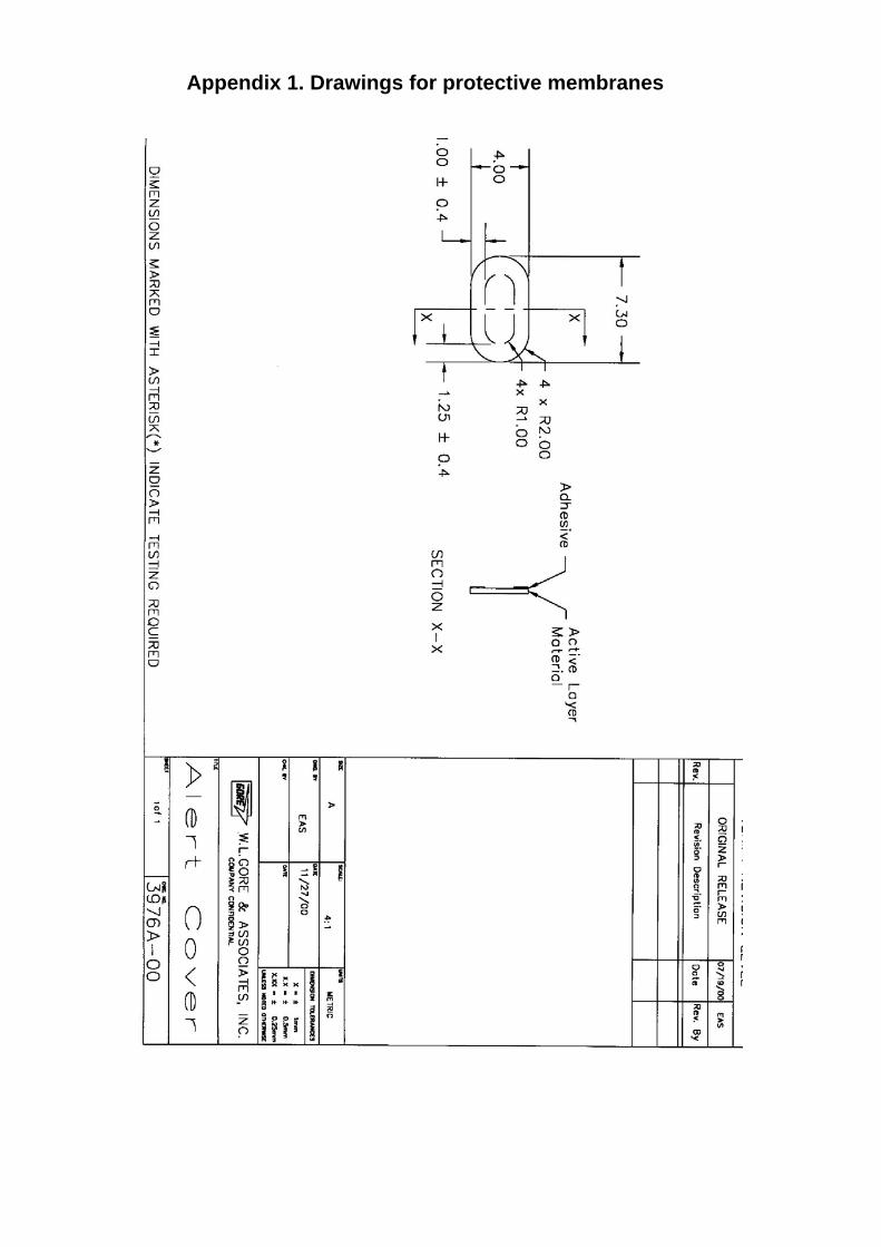
Appendix 1. Drawings for protective membranes

Appendix 2. Hyonsoo waterproof speaker

Appendix 2. Hyonsoo waterproof speaker