split air conditioner - gree comfort · installation of indoor unit ... corrosion or poor air...
TRANSCRIPT

Change for Life
Split Air Conditioner
Installation ManualResidential Air Conditioners
Thank you for choosing Residential Air Conditioners,please read this owner’s manual carefully before operation and retain it for future reference.


■ .............................................3■
■ ........................................................1
■ ............................12
Do not dispose this product as unsorted municipal waste. Collection of such waste separately for special treatment is necessary.
CONTENTS
Notices for installation
Installation dimension diagram
Installation of indoor unit .....................................................4
Check after installation and operation test■ Installation and maintenance of healthy filter .........................13
Never attempt. Be sure to follow this instruction
The physical product may differ from the drawing in this manual for different display. If there are some differences between them, please refer to the physical product as the standard.
This appliance is not intended for use by persons (including children) with reducedphysical, sensory or mental capabilities or lack of experience and knowledge, unless they have been given supervision or instruction concerning use of the appliance by a person responsible for their safety.Children should be supervised to ensure they are away from the appliance.
■ Installation of outdoor unit ...................................................8
■ Configuration of connection pipe and additional volume of refrigerant .....14

1
Notices for installation
5.Warning: Before obtaining access to terminals, all supply circuits must be disconnected.6.For appliances with type Y attachment, the instructions shall contain the substance of the following. If the supply cord is damaged, it must be replaced by the manufacturer, its service agent or similarly qualified persons in order to avoid a hazard.7.The appliance must be positioned so that the plug is accessible.8.The temperature of refrigerant line will be high; please keep the interconnection cable away from the copper tube. 9. The instructions shall state the substance of the following:
This appliance is not intended for use by persons(including children)with reduced physical, sensory or mental capabilities, or lack of experience and knowledge, unless they have been given supervision or instruction concerning use of the appliance by a person responsible for their safety. Children should be supervised to ensure that they do not play with the appliance.
Caution
Installation Site Instructions
The unit should be installed only by authorized service center according to local or government regulations and in compliance with this manual.
Before installing, please contact with local authorized maintenance center. If the unit isnot installed by the authorized service center, the malfunction may not be solveddue to incovenient contact between the user and the service personnel.When removing the unit to the other place, please firstly contact with the local authorizedservice center.
●
●
●
●
●
●
Proper installation site is vital for correct and efficient operation of the unit. Avoid the following sites where:
strong heat sources, vapours, flammable gas or volatile liquids are emitted. high-frequency electro-magnetic waves are generated by radio equipment, welders and medical equipment. salt-laden air prevails (such as close to coastal areas). the air is contaminated with industrial vapours and oils. the air contains sulphures gas such as in hot spring zones. corrosion or poor air quality exists.
1.
3.
4.
Installation Site of Indoor Unit
Select a site where the condensate can be easily drained out, and where it is easily connected to outdoor unit.
Select a place where the wall is strong enough to withstand the full weight and vibration of the unit.
Select a place where it is out of reach of children.
The air inlet and outlet should be away from the obstructions. Ensure the air can be blown through the whole room.
Be sure to leave enough space to allow access for routine maintenance. The installation site should be 98 3/7 inch or more above the floor
5.
4.
1.
2.
3.
2. Installation must be performed in accordance with the NEC/CEC by authorized person only.
2
Notices for installation
Note:
Safety Precautions for Electric Appliances
Installation Site of Outdoor Unit
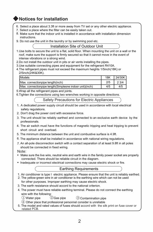
5. The minimum distance between the unit and combustive surface is 4.9ft.
1. A dedicated power supply circuit should be used in accordance with local electrical safety regulations.
2. Don't drag the power cord with excessive force.3.
The appliance shall be installed in accordance with national wiring regulations. An all-pole disconnection switch with a contact separation of at least 9.8ft in all poles should be connected in fixed wiring.
The unit should be reliably earthed and connected to an exclusive earth device by the professionals.
4. The air switch must have the functions of magnetic tripping and heat tripping to preventshort circuit and overload.
Make sure the live wire, neutral wire and earth wire in the family power socket are properly connected. There should be reliable circuit in the diagram.Inadequate or incorrect electrical connections may cause electric shock or fire.
●
●
6.
7.
Make sure that the indoor unit is installed in accordance with installation dimension
Select a place about 3.3ft or more away from TV set or any other electric appliance. Select a place where the filter can be easily taken out.
instructions.
6.7.8.
9. Do not use the unit in the laundry or by swimming pool etc.
Earthing Requirements
① ② ③ ④
1. Air conditioner is type I electric appliance. Please ensure that the unit is reliably earthed.2. The yellow-green wire in air conditioner is the earthing wire which can not be used
for other purposes. Improper earthing may cause electric shock.3. The earth resistance should accord to the national criterion.4. The power must have reliable earthing terminal. Please do not connect the earthing
wire with the following:W epip saGepip reta Contamination pipeOther place that professional personnel consider is unreliable
5. The model and rated values of fuses should accord with the silk print on fuse cover or related PCB.
1.Use bolts to secure the unit to a flat, solid floor. When mounting the unit on a wall or the roof, make sure the support is firmly secured so that it cannot move in the event of intense vibrations or a strong wind.2.Do not install the outdoor unit in pits or air vents installing the pipes.3.Use suitable connecting pipes and equipment for the refrigerant R410A.4.The refrigerant pipes must not exceed the maximum heights 1/5inch(18K) or 2/5inch(24K&30K).
5.Wrap all the refrigerant pipes and joints.6.Tighten the connections using two wrenches working in opposite directions.
Models 18K 24/30KMax. connectionpipe length(inch) 2/5 2 3/4Max. connectionpipe length(Simpleone indoor unit)(inch) 4/5 4/5
3
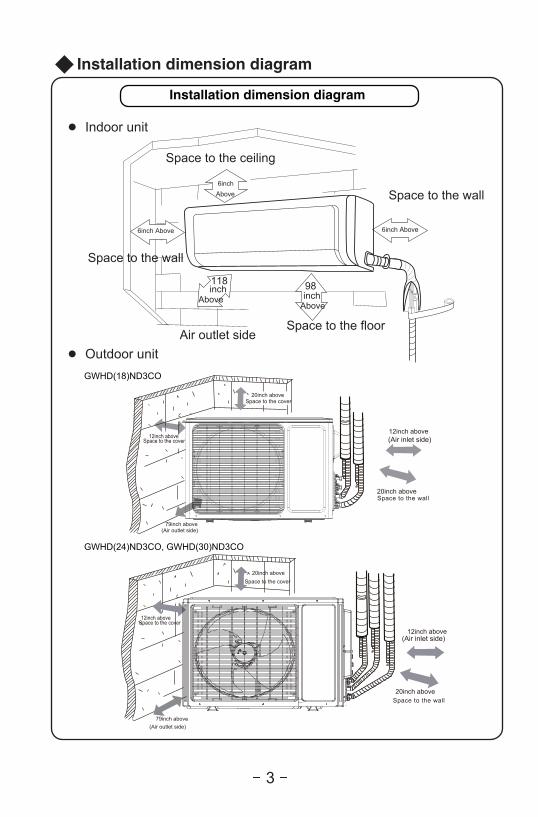
Installation dimension diagram
Space to the ceiling
Space to the wall
Space to the wall
Air outlet sideSpace to the floor
AboveAbove
6inch Above 6inch Above
Above
118inch 98
6inch
Installation dimension diagram
● Indoor unit
● Outdoor unit
inch
Space to the cover
Space to the cover
(Air inlet side)
Space to the wall
(Air outlet side)
GWHD(18)ND3CO
GWHD(24)ND3CO, GWHD(30)ND3CO
(Air inlet side)
Space to the wall
(Air outlet side)
Space to the cover
Space to the cover
20inch above
20inch above
12inch above12inch above
79inch above
20inch above
20inch above
12inch above
12inch above
79inch above

4
Installation of indoor unit
Installation of Mounting Plate 1. Mounting plate should be installed horizontally. As the water tray's outlet for the indoor unit is two-way type, during installation, the indoor unit should slightly slant to water tray's outlet for smooth drainage of condensate. 2.Fix the mounting plate on the wall with screws.3.Be sure that the mounting plate has been fixed firmly enough to withstand about 132.3 lb. Meanwhile, the weight should be evenly shared by each screw.
AB UNIT:
(Rear piping hole) (Rear piping hole)Left Right
the wall 6inchabove
Space tothe wall 6inchabove
Wall Wall
AC UNIT:
3 4/7
6 1/61
11 1/
7
23 5/6 3 3/41/3
33 3/4
1 1/9
4 2/7
Unit:inch
4 1/3 27 1/3 5 3/5
2 3/4
1
Ø2 1/6 3 1/71 1
/6Ø2 1/6
11 4/
5
1/3
37 1/4
Ø2 1/6 Ø2 1/6
21 1/3
1 2/
3
1 2/
3
5 5/8 3 1/7
5 1/6 6 7/9
Φ2 1/6
10 5
/6
Φ2 1/6
5/9 4 3/4
7 2/32
11 3
/4
1 7/
9
27 1/3
Φ2 1/6 Φ2 1/6
MB UNIT:
MC UNIT:

Drill Piping Hole
1.Slant the piping hole (Ф2 1/6 or Ф2 3/4) on the wall slightly downward
to the outdoor side. 2.Insert the piping-hole sleeve into the hole to prevent the connection piping
and wiring from being damaged when passing through the hole.
Indoor Outdoor Wall pipe Seal pad
5
Installation of indoor unit
Ф2 1/6 or Ф2 3/4
Unit:inch
34
6 3/8
6 2/7
2/5
3 1/7
1 3/8
10 1
/2
11 1
/2
6 3/7
Φ2 1/6 Φ2 1/6
12 5
/9
5 2/3 27 7 4/9
11
2 1/6 6 1/9
Φ2 3/4
1/2
3 1/2
2 1/6
Φ2 3/41 3/8
TB UNIT:
TC UNIT:
Fig.5

Connecting Indoor and Outdoor Electric Wires
6
Installation of indoor unit
Note: The insulating tube should be connected reliably withthe sleeve outside the outlet pipe. The drain hose should be slanted downward slightly, without distortion, bulge or fluctuation. Do not put the outlet in the water.
bulge distortion
Flooded
●
●
● After tightening the screws, pull the wire slightly to confirm whether it's firm or not.● ● Make sure that all wiring connections are secure and the cover plates are reinstalled
NOTE:All wires between indoor and outdoor units must be connected by the qualified electric contractor.
Electric wires must be connected correctly. Improper connection may cause malfunction.Tighten the terminal screws securely.
Make sure that the electric connections are earthed properly to prevent electric shock.
properly. Poor installation may cause fire or electric shock.
yellow-green
brown Fig.6
1.Open the front panel.2.Remove the wiring cover as shown in Fig 6.3.Make the power connection cord and pass through the hole at the back of indoor unit. 4.Reinstall the cord anchorage and wiring cover.5.Reinstall the front panel.
Wiring cover
outdoor unit connection
1.
2.
3.
Installation of Drain Hose
Connect the drain hose to the outlet pipe of the indoor unit.Bind the joint with rubber belt.
Put the drain hose into insulating tube.
Wrap the insulating tube with wide rubber belt to prevent the shift of insulating tube. Slant the drain hose downward slightly for smooth drainage of condensate.
outlet pipe of indoor unit
insulating tubeconnected
insulating tube
drain hoseoutlet pipe of indoor unit
drain hose
outlet pipe of indoor unit
outlet pipe of indoor unit
rubber belt
rubber beltrubber belt
7
右后
4.
2.
3.
●
1.
⑴ ⑵
1.2.
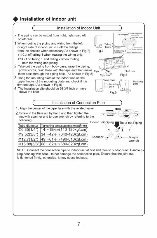
Installation of Indoor Unit
The piping can be output from right, right rear, leftor left rear.When routing the piping and wiring from the leftor right side of indoor unit, cut off the tailingsfrom the chassis when necessary(As shown in Fig.7)
Cut off tailing 1 when routing the wiring only;Cut off tailing 1 and tailing 2 when routingboth the wiring and piping.
Take out the piping from body case; wrap the piping, power cords, drain hose with the tape and then make them pass through the piping hole. (As shown in Fig.8)Hang the mounting slots of the indoor unit on theupper hooks of the mounting plate and check if it is firm enough. (As shown in Fig.9)The installation site should be 98 3/7 inch or more
above the floor.
Installation of Connection PipeAlign the center of the pipe flare with the related valve.Screw in the flare nut by hand and then tighten thenut with spanner and torque wrench by referring to the following:
NOTE: Connect the connection pipe to indoor unit at first and then to outdoor unit. Handle pi-ping bending with care. Do not damage the connection pipe. Ensure that the joint nut is tightened firmly, otherwise, it may cause leakage.
Spanner Torque wrench
PipingTaper nutIndoor unit piping
Fig.9
Mountingplate
Fixing hook Mounting plate
Right
Right rear Fig.8Left rear
Left
Fig.7Tailing 1Tailing 2
Finally wrap itwith tape
Gas side pipinginsulation
Water drainage pipe
Liquid sidePiping insulation
Gas side pipingExternal connection
electric wireLiquid side piping
(N·m)Ф6.35(1/4”)Ф9.52(3/8”)Ф12.7(1/2”)Ф15.88(5/8”)
34~42N·m(340-420kgf.cm)14~18N·m(140-180kgf.cm)
49~61N·m(490-610kgf.cm)68~82N·m(680-820kgf.cm)
Tube diameter Tightening torque,approximate
Installation of indoor unit

8
Installation of outdoor unit
Electric Wiring
3.4.5.
2.Remove the cable clamp, connect the connection cable and power cable with the terminal at the row of connection and fix the connection. The fitting line distributing must be consistent with the indoor unit terminal of line bank. Wiring should meet that of indoor unit.
1.Remove the handle at the right side plate of the outdoor unit (six screw).
Fix power connection wire by wire clamp.Ensure wire has been fixed well.Install the handle.
To the power supply
To unit B
cable cable
To unit A
GWHD(18)ND3CO
L1 L2
L1
L1
L2
L2
cable cable cablepower connecting connecting
GWHD(24)ND3CO
To the power supply
To unit BTo unit A
cableconnectionpower connection
cablecable
To unit C
connectioncable
Outdoor unit
Indoor unit
L1 L2
L1
L1
L2
L2
To the power supply
To unit BTo unit A
connectioncable
connectioncable
To unit C
connectioncable
To unit D
connectioncable
Outdoor unit
Indoor unit
L1 L2
L1
L1
L2
L2
N(1) 2 3 N(1) 2 3 N(1) 2 3 N(1) 2 3A B C D
powercable
GWHD(30)ND3CO

9
Installation of outdoor unit
Wrong wire connection may cause malfunction of some electric components.After fixing cable, ensure that leads between connection to fixed point have some space.
An all-pole disconnection switch having a contact separation of at least 3mm in all pole should be connected in fixed wiring.
The connection pipes and the connectiong wirings of the unit A ,unit B and unit C must be corresponding to each other respective.
The appliance shall be installed in accordance with national wiring regulations.
Do not install the outdoor unit where it is exposedto the sunlight.
Note: the above figures are only intended to be a simple eht ot dnopserroc ton yam dna ecnailppa eht fo margaidappearance of the units that have been purchased.
Power cable
A
BC
D
connection cable
connection cable
connection cable
connection cable
1) The power cable should be put in from the hole under connection cable cover.
2) If connecting with two indoor units, the connection cable should be put in from hole A and hole B.3) If connecting with three indoor units, the connection cable should be put in from hole A , B and C. 4) If connecting with four indoor units, the connection cable should be put in from hole A, B , C and D.
All power cables and connection cables must be protected with conduits.

10
Installation of outdoor unit
Humid air left inside the refrigerant circuit can cause compressor malfunction. After having connected the indoor and outdoor units, bleed the air and humidity from the refrigerant circuit using a vacuum pump.(1) Unscrew and remove the caps from the 2-way and 3-way valves.(2) Unscrew and remove the cap from the service valve.(3) Connect the vacuum pump hose to the service valve.(4) Operate the vacuum pump for 10-15 minutes until an absolute vacuum of 2/5 inch Hg has been reached.(5) With the vacuum pump still in operation, close the low-pressure knob on the vacuum pump coupling. Stop the vacuum pump.(6) Open the 2-way valve by 1/4 turn and then close it after 10 seconds. Check all the joints for leaks using liquid soap or an electronic leak device.(7) Turn the body of the 2-way and 3-way valves. Disconnect the vacuum pump hose.
(8) Replace and tighten all the caps on the valves.
(9) If the specification of outdoor unit gas valve is 3/8”,but curstomer needs to install 1/2”indoor unit so that it is need to use a “pipe joint subassembly” (Code 06643008) to make a conversion joint with outdoor unit gas valve and connection pipe, as show in following.
Air Purging and Leakage Test
(N·m)Ф6.35(1/4”)Ф9.52(3/8”)Ф12.7(1/2”)Ф15.88(5/8”)
34~42N·m(340-420kgf.cm)14~18N·m(140-180kgf.cm)
49~61N·m(490-610kgf.cm)68~82N·m(680-820kgf.cm)
Tube diameter Tightening torque,approximate
Vacuum pump
Vacuum pump Vacuum pump
INDOORUNIT
Connect to theindoor unit
Refrigerant fluid direction of flow
3-way valve
2-way valve
Service inlet
(2) Turn(8) Secure
(7) Turn to open fully
(2) Turn
(8) Secure
Valve cap
(6) Open by 1/4 turn
(7) Turn to open fully
(2) Turn
(8) Secure
Valve cap
conversion joint
11
Installation of outdoor unit
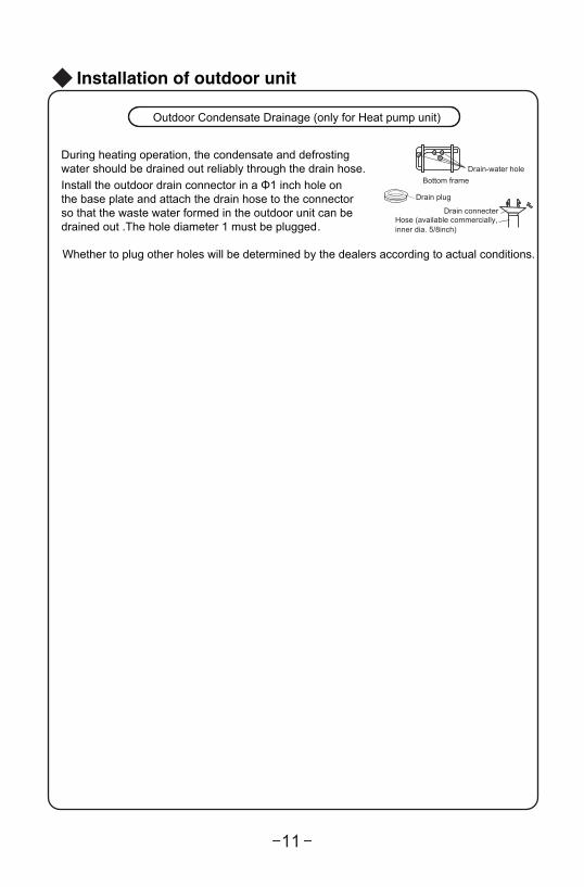
During heating operation, the condensate and defrosting water should be drained out reliably through the drain hose.Install the outdoor drain connector in a Φ1 inch hole onthe base plate and attach the drain hose to the connectorso that the waste water formed in the outdoor unit can bedrained out .The hole diameter 1 must be plugged.
Whether to plug other holes will be determined by the dealers according to actual conditions.
Drain-water holeBottom frame
Drain plug
Hose (available commercially,inner dia. 5/8inch)
Drain connecter
Outdoor Condensate Drainage (only for Heat pump unit)

12
Check after installation and operation test
Check after Installation
noitcnuflam elbissoPdekcehc eb ot smetI
Has the unit been fixed firmly? The unit may drop, shake or emit noise.
Have you done the refrigerant leakage test? It may cause insufficient cooling(heating).
Is thermal insulation sufficient? It may cause condensation.
Is water drainage satisfactory? It may cause water leakage.Is the voltage in accordance with the ratedvoltage marked on the nameplate?
It may cause electric malfunctionor damage the unit.
Is the electric wiring or pipingconnection installed correctly and securely?
It may cause electric malfunctionor damage the parts.
Has the unit been securely earthed? It may cause electrical leakage.
Is the power cord specified? It may cause electric malfunctionor damage the parts.
Is the inlet or outlet blocked? It may cause insufficient cooling(heating).
Is the length of connection pipesand refrigerant capacity recorded?
The refrigerant capacity is not accurate.
Operation Test
1.Before Operation Test(1)Do not switch on power before installation is finished completely. (2)Electric wiring must be connected correctly and securely.(3)Cut-off valves of the connection pipes should be opened.(4)All the impurities such as scraps and thrums must be cleared from the unit.2.Operation Test Method(1)Switch on power and press "ON/OFF" button on the wireless remote controller to start the operation.(2)Press MODE button to select the COOL, HEAT (Not available for cooling only unit), FAN to check whether the operation is normal or not.

Installation and maintenance of healthy filter
13
Fig. a
1.
2. (as shown in Fig.b).
3. Install the air filter properly along the arrowdirection in Fig.c, and then close the panel .
●
filter
Air filter
(as shown in Fig.a)
Fig. b
Fig. c
Lift up the front panel from its two ends, as shown by the arrow direction, and then remove the air filter.
Attach the healthy filter onto the air filter, .
Healthy
Remove the healthy filter and reinstall it after cleaning according to the installation instruction. Do not use brush or hard objects to cleanthe filter. After cleaning, be sure to dry it in the shade.
The general service life for the healthy filter is about one year under normal condition. As for silver ion filter, it is ineffective when its surface becomes black (green).
This supplementary instruction is provided for reference to the unit withhealthy filter. If the graphics provided herein are different from the actualproduct, please refer to the actual product. The quantity of healthy filters is based on the actual delivery.
Installation of Healthy Filter
Cleaning and Maintenance
Service Life

1. Standard length of connection pipe16.4ft、24.6ft、26.2ft
2. Min length of connection pipeFor the unit with standard connection pipe of 16.4ft , there is no limitationfor the min length of connection pipe. For the unit with standard connectionpipe of 24.6ft and 26.2ft, the min length of connection pipe is 9.8ft .
3. Max length of connection pipe
4. The calculation method of additional refrigerant oil and refrigerant chargingamount after prolonging connection pipe
fo sisab eht ta tf8.23 rof degnolorp si epip noitcennoc fo htgnel eht retfAstandard length, you should add 5ml of refrigerant oil for each additional
.epip noitcennoc fo tf4.61The calculation method of additional refrigerant charging amount (on the
(1) Additional refrigerant charging amount= prolonged length of liquid pipe × additionalrefrigerant charging amount per meter
(2) When the length of connection pipe is above 16.4ft gnidrocca tnaregirfer dda ,to the prolonged length of liquid pipe. The additional refrigerant chargingamount per meter is different according to the diameter of liquid pipe. See Sheet 2.
basis of liquid pipe):
Sheet 1 Max length of connection pipe Unit: ft
Configuration of connection pipe and additional volume of refrigerant
14
Capacity Max length of
connection pipe Capacity
Max length of connection pipe
5000 Btu/h(1465 W) 49.2
24000 Btu/h(7032 W) 82
7000 Btu/h(2051 W)
28000 Btu/h(8204 W) 98.4
9000 Btu/h(2637 W)
36000 Btu/h(10548 W)
12000 Btu/h(3516 W) 65.6
42000 Btu/h(12306 W)
18000 Btu/h(5274 W) 82
48000 Btu/h(14064 W)
49.2
49.2 98.4
98.4
98.4

15
Sheet 2. Additional refrigerant charging amount for R22 R407C R410A and R134a
Note: The additional refrigerant charging amount in Sheet 2 is recommendedvalue, not compulsory.
Diameter of connection pipe mm Indoor unit throttle Outdoor unit throttle
Liquid pipe Gas pipe Cooling only,
cooling and heating
(oz/ft)
Cooling only Cooling and
heating
1/4” 3/8” or 1/2” 0.2
1/4” or or 0.5
or 1.1 0.3 1.3
or 5/4” 1.8 0.6
- 2.7
- 3.8
Configuration of connection pipe and additional volume of refrigerant
3/8”
1/2”
5/8”
3/4”7/8”
5/8” 3/4”
3/4” 7/8”
1”
(oz/ft) (oz/ft)
0.2
0.2
2.7
3.8
0.2
0.5
1.3
2.7
3.8


Add: West Jinji Rd, Qianshan, Zhuhai, Guangdong, China, 519070Tel: (+86-756) 8522218 Fax: (+86-756) 8669426E-mail: [email protected] www.gree.com
GREE ELECTRIC APPLIANCES, INC. OF ZHUHAI
66129911482