split air conditioner - gree€¦ · split air conditioner if you have lost the owner’s manual,...
TRANSCRIPT

Split Air Conditioner
If you have lost the Owner’s Manual, please contact the local agent or visitwww.gree.com or sent email to [email protected] for electronic version.
Thank you for choosing our product.For proper operation, please read and keep this manual carefully .
GWH09TA-K3DNA1B/OGWH12TB-K3DNA1B/OGWH18TC-K3DNA1B/O DREDGWH24TD-K3DNA1C/O DREDGWH28TD-K3DNA1B/O DRED
DREDDRED
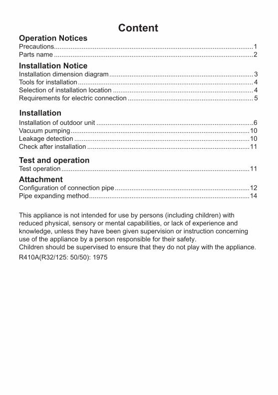
ContentOperation NoticesPrecautions............................................................................................................1Parts name ............................................................................................................2
Installation NoticeInstallation dimension diagram .............................................................................. 3Tools for installation ............................................................................................... 4Selection of installation location ............................................................................ 4Requirements for electric connection .................................................................... 5
InstallationInstallation of outdoor unit .....................................................................................6Vacuum pumping .................................................................................................10Leakage detection ...............................................................................................10Check after installation ........................................................................................11
Test and operationTest operation ......................................................................................................11
Attachment .........................................................................12
Pipe expanding method .......................................................................................14
R410A(R32/125: 50/50): 1975
This appliance is not intended for use by persons (including children) with reduced physical, sensory or mental capabilities, or lack of experience and knowledge, unless they have been given supervision or instruction concerning use of the appliance by a person responsible for their safety.Children should be supervised to ensure that they do not play with the appliance.
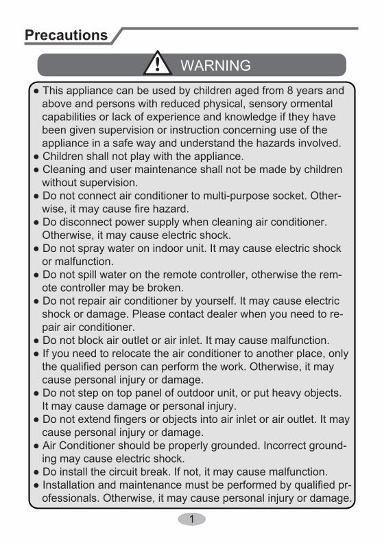
Precautions
● This appliance can be used by children aged from 8 years and above and persons with reduced physical, sensory ormental capabilities or lack of experience and knowledge if they have been given supervision or instruction concerning use of the appliance in a safe way and understand the hazards involved.● Children shall not play with the appliance.● Cleaning and user maintenance shall not be made by children without supervision.● Do not connect air conditioner to multi-purpose socket. Other- wise, it may cause fire hazard.● Do disconnect power supply when cleaning air conditioner. Otherwise, it may cause electric shock.● Do not spray water on indoor unit. It may cause electric shock or malfunction.● Do not spill water on the remote controller, otherwise the rem- ote controller may be broken.● Do not repair air conditioner by yourself. It may cause electric shock or damage. Please contact dealer when you need to re- pair air conditioner.● Do not block air outlet or air inlet. It may cause malfunction.● If you need to relocate the air conditioner to another place, only the qualified person can perform the work. Otherwise, it may cause personal injury or damage.● Do not step on top panel of outdoor unit, or put heavy objects. It may cause damage or personal injury.● Do not extend fingers or objects into air inlet or air outlet. It may cause personal injury or damage.● Air Conditioner should be properly grounded. Incorrect ground- ing may cause electric shock.● Do install the circuit break. If not, it may cause malfunction.● Installation and maintenance must be performed by qualified pr- ofessionals. Otherwise, it may cause personal injury or damage.
11
WARNING

Parts name
Outdoor Unitair inlet
Connection wire
air outlet
Precautions
Working temperature range
Indoor side DB/WB(℃ ) Outdoor side DB/WB(℃ )Maximum cooling 32/23 43/26Maximum heating 27/- 24/18
● The operating temperature range (outdoor temperature) for cooling only unit is 18℃ ~48℃ ; for heat pump unit is -15℃ ~ 48℃ .
2
Actual product may be different from above graphics, please refer to actual products.
NOTICE:

Installation dimension diagram
Drainage pipe
At l
east
50c
m
At least 50cm
At least
30cm
At least 200cm
Spa
ce to
the
obst
ruct
ion
Space to the obstruction
Space to the
obstruction
Space to the obstruction
At least 30cmSpace to the wall
3

Tools for installation1 Level meter 2 Screw driver 3 Impact drill4 Drill head 5 Pipe expander 6 Torque wrench7 Open-end wrench 8 Pipe cutter 9 Leakage detector
10 Vacuum pump 11 Pressure meter 12 Universal meter
13 Inner hexagon spanner 14 Measuring tape
Note:● Please contact the local agent for installation.● Don't use unqualified power cord.
4
Selection of installation locationBasic requirement
Outdoor unit
Installing the unit in the following places maycause malfunction. If it is un-avoidable, please consult the localdealer:
1.The place with strong heat sources, vapors, flammableor explosive gas, or volatile objects spread in the air.
2.The place with high-frequency devices (such as welding machine, medical equipment).
3. The place near coast area.4. The place with oil or fumes in the air.5. The place with sulfureted gas.6. Other places with special circumstances.7. The appliance shall not be installed in the laundry.
will not affect neighborhood.2. The location should be well ventilated and dry, in which the outdoor unit won't be exposed directly to sunlight or strong wind.3. The location should be able to withstand the weight of outdoor unit.4. Make sure that the installation follows the requirement of installation dimension diagram.5. Select a location which is out of reach for children and far away from animals or plants.If it is unavoidable, please add the fence for safety purpose.

5
Requirements for electric connectionSafety precaution
Grounding requirement
1. Must follow the electric safety regulations when installing the unit.
circuit break.3. Make sure the power supply matches with the requirement of air conditioner. Unstable power supply or incorrect wiring or malfunction. Please install proper power supply cables before using the air conditioner.4. Properly connect the live wire, neutral wire and grounding wire of power socket.5. Be sure to cut off the power supply before proceeding any work related to electricity and safety.
7. If the supply cord is damaged, it must be replaced by the manufacturer, its
8. The temperature of refrigerant circuit will be high, please keep the interconnec- tion cable away from the copper tube.9. The appliance shall be installed in accordance with national wiring regulations.10.Installation must be performed in accordance with the requirement of NEC and CEC by authorized personnel only
grounding with specialized grounding device by a professional. Please make sure it is always grounded effectively, otherwise it may cause electric shock.2. The yellow-green wire in air conditioner is grounding wire, which can't be used for other purposes.3. The grounding resistance should comply with national electric safety regulations.4. The appliance must be positioned so that the plug is accessible.5. An all-pole disconnection switch having a contact separation of at least 3mm in
6. Including an circuit break with suitable capacity, please note the following table. Air switch should be included magnet buckle and heating buckle function, it can protect the circuit-short and overload. (Caution: please do not use the fuse only for protect the circuit)
Air-conditioner Circuit break capacity
24、28K 25A18K 16A
16A12K09K 10A

Installation of outdoor unitStep one: fix the support of outdoor unit (select it according to the actual installation situation)1. Select installation location according to the house structure.2. Fix the support of outdoor unit on the selected location with expansion screws.
Note:● Take sufficient protective measures when installing the outdoor unit.● Make sure the support can withstand at least four times of the unit weight.● The outdoor unit should be installed at least 3cm above the floor in order to install drain joint.● For the unit with cooling capacity of 2300W ~5000W, 6 expansion screws are needed; for the unit with cooling capacity of 6000W ~8000W, 8 expansion screws are needed; for the unit with cooling capacity of 10000W ~16000W, 10 expansion screws are needed.
Step two: install drain joint(Only for cooling and heating unit)1. Connect the outdoor drain joint into the hole on the chassis, as shown in the picture below.2. Connect the drain hose into the drain vent.
chassisoutdoor drain joint
Drain hose
drain vent
Step three: fix outdoor unit1. Place the outdoor unit on the support.2. Fix the foot holes of outdoor unit with bolts.
foot holes
foot holes
at least 3cm above the floor
6

7
Installation of outdoor unitStep four: connect indoor and outdoor pipes1. Remove the screw on the right han- dle of outdoor unit and then remove the handle.
2. Remove the screw cap of valve and aim the pipe joint at the bellmouth of pipe.
3. Pretightening the union nut with hand.
4. Tighten the union nut with torque wrench by referring to the sheet below.
gas pipe
liquid pipe
liquidvalve
gas valve
union nut
pipe joint
Hex nut diameter Tightening torque (N.m)
Φ 6Φ 9.52Φ 12Φ 16Φ 19
30~4045~5560~6570~75
15~20
1. Remove the wire clip; connect the power connection cord and signal control cord to the wiring terminal according to the color; fix them with screws.
handle
screw
L
N(1) 2 3
NL N
Indoor unit
18、24、28K Heat pump type:
09、12K Heat pump type:
yellow-green
yellow-green
2 3 L
L N
NN(1)
blue blueblack brown brown
Indoor unit connection POWERPOWERL N
DREDMODULE
RJ45 CONNECTOR
8
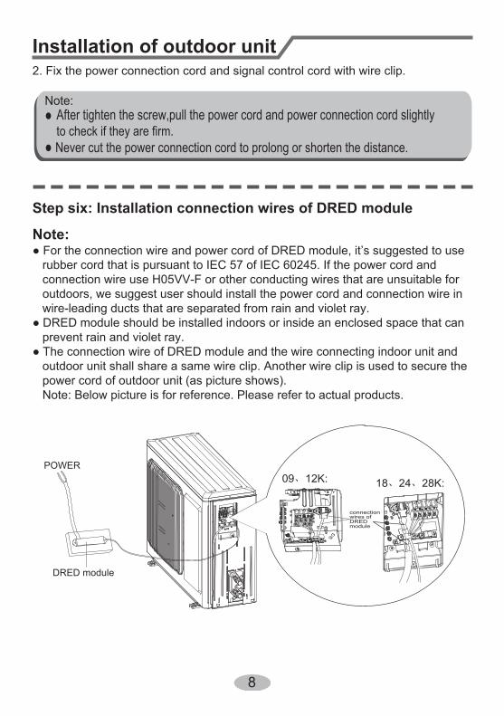
Installation of outdoor unit2. Fix the power connection cord and signal control cord with wire clip.
Step six: Installation connection wires of DRED module
Note:● For the connection wire and power cord of DRED module, it’s suggested to use rubber cord that is pursuant to IEC 57 of IEC 60245. If the power cord and connection wire use H05VV-F or other conducting wires that are unsuitable for outdoors, we suggest user should install the power cord and connection wire in wire-leading ducts that are separated from rain and violet ray.● DRED module should be installed indoors or inside an enclosed space that can prevent rain and violet ray. ● The connection wire of DRED module and the wire connecting indoor unit and outdoor unit shall share a same wire clip. Another wire clip is used to secure the power cord of outdoor unit (as picture shows). Note: Below picture is for reference. Please refer to actual products.
POWER
DRED module
After tighten the screw,pull the power cord and power connection cord slightlyto check if they are firm.
Note:
● Never cut the power connection cord to prolong or shorten the distance.
connection wires of DRED module
09、12K: 18、24、28K:
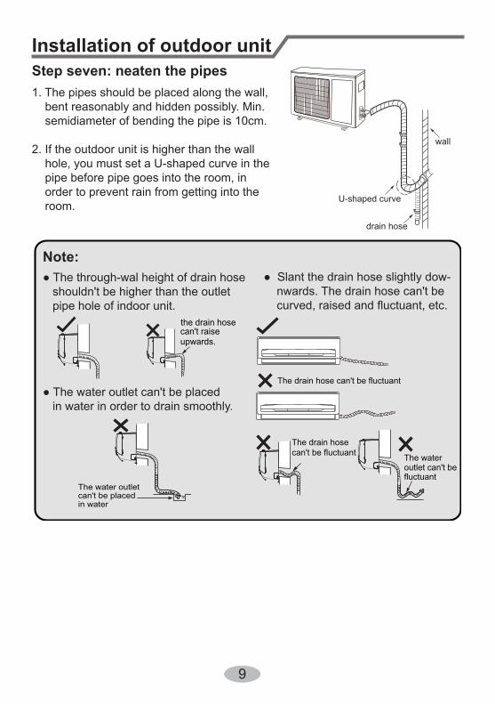
Step seven: neaten the pipes1. The pipes should be placed along the wall, bent reasonably and hidden possibly. Min. semidiameter of bending the pipe is 10cm.
2. If the outdoor unit is higher than the wall hole, you must set a U-shaped curve in the pipe before pipe goes into the room, in order to prevent rain from getting into the room.
● The through-wal height of drain hose shouldn't be higher than the outlet pipe hole of indoor unit.
● Slant the drain hose slightly dow- nwards. The drain hose can't be curved, raised and fluctuant, etc.
● The water outlet can't be placed in water in order to drain smoothly.
U-shaped curve
wall
drain hose
the drain hosecan't raiseupwards.
The drain hose can't be fluctuant
The drain hosecan't be fluctuant The water
outlet can't befluctuant
The water outlet can't be placedin water
Note:
Installation of outdoor unit
9
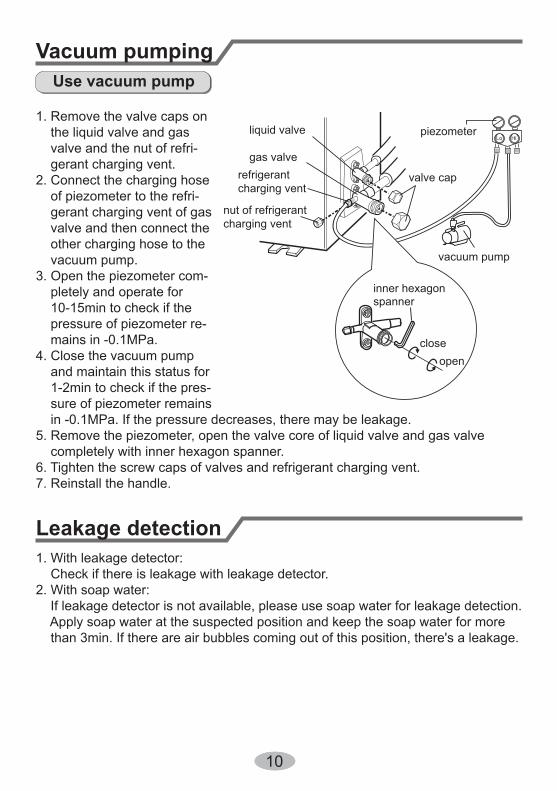
Vacuum pumping
Leakage detection
1. Remove the valve caps on the liquid valve and gas valve and the nut of refri- gerant charging vent.2. Connect the charging hose of piezometer to the refri- gerant charging vent of gas valve and then connect the other charging hose to the vacuum pump.3. Open the piezometer com- pletely and operate for 10-15min to check if the pressure of piezometer re- mains in -0.1MPa.4. Close the vacuum pump and maintain this status for 1-2min to check if the pres- sure of piezometer remains in -0.1MPa. If the pressure decreases, there may be leakage.5. Remove the piezometer, open the valve core of liquid valve and gas valve completely with inner hexagon spanner.6. Tighten the screw caps of valves and refrigerant charging vent.7. Reinstall the handle.
Use vacuum pump
liquid valve
gas valverefrigerant charging vent
nut of refrigerantcharging vent
vacuum pump
piezometer
valve cap
Lo Hi
inner hexagonspanner
openclose
1. With leakage detector: Check if there is leakage with leakage detector.2. With soap water: If leakage detector is not available, please use soap water for leakage detection. Apply soap water at the suspected position and keep the soap water for more than 3min. If there are air bubbles coming out of this position, there's a leakage.
10

Check after installation
Test operation
● Check according to the following requirement after finishing installation.
Items to be checked Possible malfunctionHas the unit been installed firmly? The unit may drop, shake or emit noise.Have you done the refrigerant leakage test?
It may cause insufficient cooling (heating) capacity.
Is heat insulation of pipeline sufficient? It may cause condensation and water dripping.
Is water drained well? It may cause condensation and water dripping.
Is the voltage of power supply accord-ing to the voltage marked on thenameplate?
It may cause malfunction or damaging the parts.
Is electric wiring and pipeline installedcorrectly?
It may cause malfunction or damaging the parts.
Is the unit grounded securely? It may cause electric leakage.
Does the power cord follow the speci-fication?
It may cause malfunction or damaging the parts.
Is there any obstruction in the air inlet and outlet?
It may cause insufficient cooling (heating) capacity.
The dust and sundries caused during installation are removed?
It may cause malfunction or damaging the parts.
The gas valve and liquid valve of connection pipe are open completely?
It may cause insufficient cooling (heating) capacity.
1. Preparation of test operation ● The client approves the air conditioner. ● Specify the important notes for air conditioner to the client.2. Method of test operation ● Put through the power, press ON/OFF button on the remote controller to start operation. ● Press MODE button to select AUTO, COOL, DRY, FAN and HEAT to check whether the operation is normal or not. ● If the ambient temperature is lower than 16℃ , the air conditioner can’t start cooling.
11

Configuration of connection pipe1. Standard length of connection pipe ● 5m, 7.5m, 8m.
4. The additional refrigerant oil and refrigerant charging required after prolonging connection pipe ● After the length of connection pipe is prolonged for 10m at the basis of standard length, you should add 5ml of refrigerant oil for each additional 5m of connection pipe. ● The calculation method of additional refrigerant charging amount (on the basis of liquid pipe): Additional refrigerant charging amount = prolonged length of liquid pipe × additional refrigerant charging amount per meter ● When the length of connection pipe is above 5m, add refrigerant according to the prolonged length of liquid pipe. The additional refrigerant charging amount per meter is different according to the diameter of liquid pipe. See the following sheet.
Cooling capacity
Cooling capacity
5000Btu/h(1465W)
24000Btu/h(7032W)
7000Btu/h(2051W)
28000Btu/h(8204W)
9000Btu/h(2637W)
36000Btu/h(10548W)
12000Btu/h(3516W)
42000Btu/h(12306W)
18000Btu/h(5274W)
48000Btu/h(14064W)
Max height difference
Max height difference
Max length of connec-tion pipe
Max length of connec-tion pipe
15 255 10
15 305 10
15 305 20
20 3010 20
25 3010 20
2.Min. length of connection pipe is 3m.
3.Max. length of connection pipe and max. high difference.
12
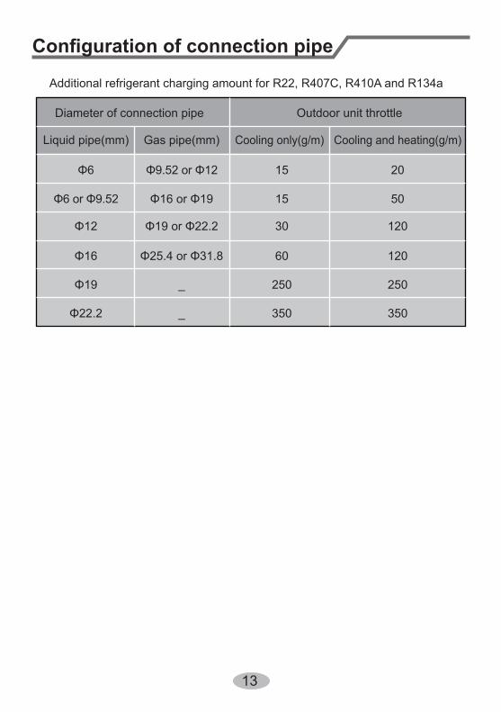
Additional refrigerant charging amount for R22, R407C, R410A and R134a
Diameter of connection pipe
Liquid pipe(mm) Gas pipe(mm)
Φ6
Φ6 or Φ9.52
Φ12
Φ16
Φ19
Φ22.2
Φ9.52 or Φ12
Φ16 or Φ19
Φ19 or Φ22.2
Φ25.4 or Φ31.8
_
_
Cooling only(g/m) Cooling and heating(g/m)
15
15
30
60
250 250
350350
120
120
50
20
Outdoor unit throttle
Configuration of connection pipe
13

Pipe expanding methodNote:Improper pipe expanding is the main cause of refrigerant leakage. Please expandthe pipe according to the following steps:A: Cut the pipe● Confirm the pipe length according to the distance of indoor unit and outdoor unit.● Cut the required pipe with pipe cutter.
pipe
pipe cutter
leaning uneven burr
B: Remove the burrs● Remove the burrs with shaper and prevent the burrs from getting into the pipe.
downwards
pipe
shaper
C: Put on suitable insulating pipeD: Put on the union nut● Remove the union nut on the indoor connection pipe and outdoor valve; install the union nut on the pipe.
union pipe
pipe
E: Expand the port● Expand the port with expander.
Note:● "A" is different according to the diameter, please refer to the sheet below:
expander
hardmold
pipe
F: Inspection● Check the quality of expanding port. If there is any blemish, expand the port again according to the steps above.
the length is equal
improper expanding
leaning damagedsurface
crack uneventhickness
smooth surface
Outer diameter(mm)
A(mm)
Max Min
Φ6-6.35(1/4")
Φ9.52(3/8")
Φ12-12.7(1/2")
Φ15.8-16(5/8")
1.3 0.7
1.6 1.0
1.8 1.0
2.4 2.2
14

Add: West Jinji Rd, Qianshan, Zhuhai, Guangdong, China, 519070Tel: (+86-756) 8522218 Fax: (+86-756) 8669426E-mail: [email protected] www.gree.com
GREE ELECTRIC APPLIANCES, INC. OF ZHUHAI
66160000140