split-type,air conditioners no. ob227 revised edition-b
TRANSCRIPT

SERVICE MANUAL
SPLIT-TYPE,AIR CONDITIONERSSPLIT-TYPE,HEAT PUMP AIR CONDITIONERS
CONTENTS
1. TECHNICAL CHANGES ····································22. PART NAMES AND FUNCTIONS······················43. INDOOR/OUTDOOR
CORRESPONDENCE TABLE ···························74. INDOOR UNITS COMBINATION ·······················85. SPECIFICATION···············································136. NOISE CRITERIA CURVES···························· 197. OUTLINES AND DIMENSIONS ······················ 228. WIRING DIAGRAM ··········································289. REFRIGERANT SYSTEM DIAGRAM ··············35
10. PERFORMANCE CURVES ······························4611. MICROPROCESSOR CONTROL···················10212. SERVICE FUNCTIONS···································12013. TROUBLESHOOTING····································12214. DISASSEMBLY INSTRUCTIONS···················14815. PARTS LIST····················································16616. OPTIONAL PARTS·········································184
Wireless typeModelsMSC-07RV - (WH) · MU-07RV -MSC-09RV - (WH) · MU-09RV -MSC-12RV - (WH) · MU-12RV -
MSC-07RV - (WH) · MUH-07RV -MSC-09RV - (WH) · MUH-09RV -MSC-12RV - (WH) · MUH-12RV -
Multi system type
MSC-07RV - (WH) · MUX-10RV -MSC-09RV - (WH) · MUX-18RV -MSC-12RV - (WH) · MUX-24RV -
Inverter controlled multi system type
· MXZ-18RV -· MXZ-32RV - E1
E1
E1E1
E1E1
E1E1
E1E1
E1E1
E1E1
E1E1
E1E1
E1E1
No. OB227REVISED EDITION-B
MSC-07RV -MSC-09RV -MSC-12RV - E1
E1
E1
Revision:• MUX-10/18/24RV - has been added.• MXZ-18/32RV - has been added.• Noise criteria curves has been added.• Performance data has been added.• Specification has been partially modified.• Refrigerant system diagram has been partially
modified.• Please void OB227 REVISED EDITION-A
E1
E1
NOTE: (Only MXZ-32RV - )This manual describes technical data of MSCtype indoor unit .For other indoor unit refer to the service manualsNo. OB229 REVISED EDITION-A of correspond-ing models.
E1

2
TECHNICAL CHANGES
MS-07NV22 -MSH-07NV22 -MSX-05NV--
MS-09NV22 -MSH-09NV22 -MSX-09NV--
MS-12NV22 -MSH-12NV22 -MSX-12NV--
1. Switch SW2 has added on the indoor electronic control P.C. board.• Indoor unit model has changed. Indoor units for COOL only type (MU and MUX) and COOL and HEAT type (MUH and
MXZ)are common specifications. Set switch SW2-2
according to the type of outdoor unit.• Change switch SW2-1 for setting AUTO RESTART FUNCTION ON/OFF.
E1
E1
E1
E1
E1
E1
E1
E1
E1
1
MSC-07RV - E1
MSC-09RV - E1
MSC-12RV - E1
1 2
SW21 2
AUTO RESTART FUNCTION :OFF
AUTO RESTART FUNCTION :ON
OUTDOOR UNIT MU & MUX type
OUTDOOR UNIT MUH & MXZ type
Set of switch SW2
1 2
SW21 2
When the units are shipped from the factory, switch SW2 is as follows. SW2-1: AUTO RESTART FUNCTION OFF SW2-2: MUH type
2. SLEEP MODE function has been removed. 3. ECONO COOL operation has been added.4. SWING button is removed, but SWING MODE function is available by VANE CONTROL button.
MU-07NV - MU-07RV -MUH-07NV - MUH-07RV -MU-09NV - MU-09RV -MUH-09NV - MUH-09RV -MU-12NV - MU-12RV -MUH-12NV - MUH-12RV -1. Outdoor model has changed.
E1E2
E1E2
E1E2
E1E2
E1E2
E1E2

3
MUX-10NV - MUX-10RV -1.Outdoor model name has changed.2 Refrigerant filling capacity has changed. (1.15kg 1.0kg)
MUX-18NV - MUX-18RV -1.Outdoor model name has changed.2 Capillary tube has changed.
([3.0O[1.4O1000 [3.0O[1.4O1100)([3.0O[1.4O600 [3.0O[1.6O1100)([3.0O[1.4O150 [3.0O[1.6O300)
MUX-24NV - MUX-24RV -1.Outdoor model name has changed.2 Refrigerant filling capacity has changed. (1.15+1.15kg 1.0+1.0kg))
MXZ-18NV - MXZ-18RV -1.Outdoor model name has changed.2.Possibly connected indoor units combination was changed.
(MSH-09NV(2) - O2 MSC-09RV - O2)
(MSH-07NV(2) - + MSH-12NV(2) - MSC-07RV - + MSC-12RV - )
MXZ-32NV - MXZ-32RV -1.Outdoor model name has changed.2.Possibly connected indoor units were changed.
(MSH-07NV(2) - MSC-07RV - )
(MSH-09NV(2) - MSC-09RV - )
(MSH-12NV(2) - MSC-12RV - )
(MSH-18NV - MSH-18NV - )
3.Control P.C. board has changed.4.Compressor frequency controll has partly changed.
E4E3
E1E2
E1E2
E1E2
E1E2
E1E1E2E2
E1E2
E1E2
E1E1
E1E1
E1E1
4
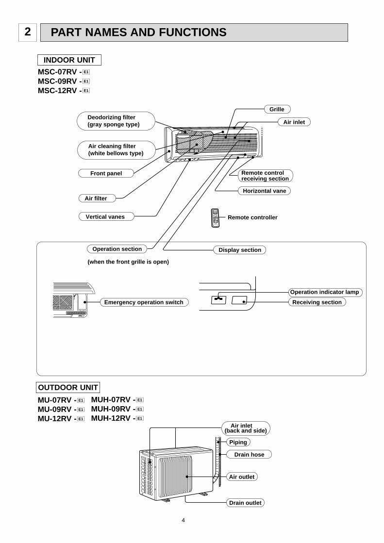
PART NAMES AND FUNCTIONS2
INDOOR UNIT
MSC-07RV -MSC-09RV -MSC-12RV - E1
E1
E1
Emergency operation switch
Operation section
Horizontal vaneAir filter
Deodorizing filter(gray sponge type)
Vertical vanes
Air inlet
Grille
Remote controlreceiving section
Remote controller
Display section
(when the front grille is open)
Operation indicator lamp
Receiving section
Air cleaning filter(white bellows type)
Front panel
Air inlet
Piping
Drain hose
Air outlet
Drain outlet
(back and side)
OUTDOOR UNIT
MU-07RV -MU-09RV -MU-12RV - E1
E1
E1 MUH-07RV -MUH-09RV -MUH-12RV - E1
E1
E1

5
OUTDOOR UNIT
MUX-10RV- E1
MUX-24RV- E1
Air inlet(back and side)
Piping
Drainage hose
Air outlet
Drain outlet
Air inlet
Air outlet
(back and side)
Model indication
Air inlet
Piping
Air outlet
Drain outlet
Drainage hose
(back and side)
MXZ-18RV- E1
MXZ-32RV- E1
MUX-18RV- E1

6
Signal transmitting section
Operation display section
OPERATE /STOP(ON /OFF)button
OPERATION SELECT button
FAN SPEED CONTROL button
ECONO COOL button
ON-TIMER buttonCLOCK SET button
HR. buttonMIN. button
(TIME SET button)
TEMPERATURE buttons
VANE CONTROL button
OFF-TIMER button
RESET button
ON/OFF TOOWARM
TOOCOOL
HR. MIN.CLOCK
RESET
CLOCK
6 00 1 1 00
MODE
FAN VANE
START STOP
ECONO COOL
AM PM
I FEEL COOL DRY FAN
MU-07RV -MU-09RV -MU-12RV -MUX-10RV -MUX-18RV -MUX-24RV - E1
E1
E1
E1
E1
E1
MUH-07RV -MUH-09RV -MUH-12RV -MXZ-18RV -MXZ-32RV - E1
E1
E1
E1
E1
Signal transmitting section
Operation display section
OPERATE /STOP(ON /OFF)button
OPERATION SELECT button
FAN SPEED CONTROL button
ON-TIMER buttonCLOCK SET button
HR. buttonMIN. button
(TIME SET button)
TEMPERATURE buttons
VANE CONTROL button
OFF-TIMER button
RESET button
ON/OFF TOOWARM
TOOCOOL
HR. MIN.CLOCK
RESET
CLOCK
MODE
FAN VANE
START STOPECONO COOL button
ECONO COOL
I FEEL COOL DRY HEAT
6 00 1 1 00AM PM
WThe remote controller is packed with the outdoor unit (MU& MUH type).
WThe remote controller is packed with the outdoor unit (MUH& MXZ type).

7
3 INDOOR / OUTDOOR CORRESPONDENCE TABLE
There is no combination other than this table.
MXZ-32RV- E1
MXZ-18RV- E1
OUTDOOR UNIT
Com
bina
tion
of th
e co
nnec
tabl
e in
door
uni
ts
07+07+07
07+07+09
07+07+(12 or 13)
07+07+18
07+09+09
07+09+(12 or 13)
07+09+18
07+(12 or 13)+(12 or 13)
07+(12 or 13)+18
07+18+18
09+09+09
09+09+(12 or 13)
09+09+18
09+(12 or 13)+(12 or 13)
09+(12 or 13)+18
09+18+18
(12 or 13)+(12 or 13)+(12 or 13)
(12 or 13)+(12 or 13)+18
07+07+07+07
07+07+07+09
07+07+07+(12 or 13)
07+07+07+18
07+07+09+09
07+07+09+(12 or 13)
07+07+09+18
07+07+(12 or 13)+(12 or 13)
07+07+(12 or 13)+18
07+09+09+09
07+09+09+(12 or 13)
07+09+09+18
07+09+(12 or 13)+(12 or 13)
09+09+09+09
09+09+09+(12 or 13)
09+09+09+18
09+09+(12 or 13)+(12 or 13)
OUTDOOR UNIT
09+09
07+12
MXZ-18RV
MXZ-32RV

8
INDOOR UNITS COMBINATION4
Outdoor unitpower consumption
(kW)
07
09
12
07+12
09+09
Indoor unitscombination Unit BUnit A
Cooling capacity (kW)
Total220V 240V
Current(A)
Power factor(%)
2.3
2.5
3.4
2.0
2.25
-
-
-
2.5
2.25
2.3(1.6 - 2.8)
2.5(1.7 - 3.0)
3.4(1.8 - 3.8)
4.5(2.0 - 4.5)
4.5(1.9 - 4.5)
1.02(0.855 - 1.33)
1.05(0.855 - 1.36)
1.45(0.855 - 1.63)
2.00(0.91- 2.00)
2.00(0.91 - 2.00)
5.20
5.36
7.40
10.21
10.21
89 - 90
89 - 90
89 - 90
89 - 90
89 - 90
4.72
4.86
6.71
9.26
9.26
Outdoor unitpower consumption
(kW)
07
09
12
07+12
09+09
Indoor unitscombination Unit BUnit A
Heating capacity (kW)
Total220V 240V
Current(A)
Power factor(%)
3.3
3.6
4.0
2.7
2.9
-
-
-
3.1
2.9
3.3(2.0 - 4.0)
3.6(2.0 - 4.5)
4.0(2.2 - 4.7)
5.8(2.1 - 5.8)
5.8(2.0 - 5.8)
1.45(0.69 - 1.60)
1.47(0.69 - 1.62)
1.63(0.69 - 1.69)
1.785(0.69 - 1.785)
1.785(0.69 - 1.785)
7.40
7.50
8.32
9.02
9.02
89 - 90
89 - 90
89 - 90
90 - 90
90 - 90
6.71
6.80
7.54
8.26
8.26
MXZ-18RVNOTE:Electrical data is for outdoor unit only.

9
07
09
12(13)
18
07+07
07+09
07+12(13)
07+18
09+09
09+12(13)
09+18
12(13)+12(13)
12(13)+18
18+18
07+07+07
07+07+09
07+07+12(13)
07+07+18
07+09+09
07+09+12(13)
07+09+18
07+12(13)+12(13)
07+12(13)+18
07+18+18
90
90
90
90
90
90
90
90
90
90
90
90
90
90
90
90
90
90
90
90
90
90
90
90
4.63
5.42
6.57
8.52
7.55
8.70
11.02
12.69
9.86
12.18
15.65
15.65
15.65
15.65
14.95
14.95
14.95
14.95
14.95
14.95
14.95
14.95
14.95
14.95
5.05
5.91
7.17
9.29
8.23
9.49
12.02
13.84
10.76
13.28
17.07
17.07
17.07
17.07
16.31
16.31
16.31
16.31
16.31
16.31
16.31
16.31
16.31
16.31
2.2(1.8-2.7)
2.8(1.8-3.2)
4.0(2.2-4.5)
5.0(2.2-5.4)
4.4(3.0-5.4)
5.0(3.0-6.0)
6.2(3.0-7.2)
7.2(3.0-7.6)
5.6(3.0-6.4)
6.8(3.0-7.6)
7.8(3.0-8.6)
8.0(3.0-8.8)
8.0(3.0-8.8)
8.0(3.0-8.8)
6.6(3.7-8.1)
7.2(3.7-8.5)
8.0(3.7-9.0)
8.0(3.7-9.0)
7.8(3.7-8.8)
8.0(3.7-9.0)
8.0(3.7-9.0)
8.0(3.7-9.0)
8.0(3.7-9.0)
8.0(3.7-9.0)
1.00(0.96-1.14)
1.77(0.96-1.36)
1.42(1.00-1.63)
1.84(1.00-1.99)
1.63(1.30-2.03)
1.88(1.30-2.23)
2.38(1.30-3.60)
2.74(1.30-3.60)
2.13(1.30-3.60)
2.63(1.30-3.60)
3.29(1.30-3.60)
3.38(1.30-3.60)
3.38(1.30-3.60)
3.38(1.30-3.60)
3.23(1.30-3.96)
3.23(1.30-3.96)
3.23(1.30-3.96)
3.23(1.30-3.96)
3.23(1.30-3.96)
3.23(1.30-3.96)
3.23(1.30-3.96)
3.23(1.30-3.96)
3.23(1.30-3.96)
3.23(1.30-3.96)
-
-
-
-
-
-
-
-
-
-
-
-
-
-
-
-
-
-
-
-
-
-
-
-
-
-
-
-
-
-
-
-
-
-
-
-
-
-
2.2
2.8
3.8
4.2
2.8
3.6
4.0
3.1
3.6
3.25
-
-
-
-
2.2
2.8
4.0
5.0
2.8
4.0
5.0
4.0
4.5
4.0
2.2
2.2
2.1
1.9
2.8
2.5
2.3
3.1
2.8
3.25
2.2
2.8
4.0
5.0
2.2
2.2
2.2
2.2
2.8
2.8
2.8
4.0
3.5
4.0
2.2
2.2
2.1
1.9
2.2
1.9
1.7
1.8
1.6
1.5
Indoor unitscombination Unit A Unit B Unit C Unit D
Cooling capacity (kw)
Total
Outdoor unitpower consumption
(kw)
Current(A)
Powerfactor(%)220V 240V
NOTE: Electrical data is for outdoor unit only.MXZ-32RV

10
Indoor unitscombination Unit A Unit B Unit C Unit D
Cooling capacity (kw)
Total
Outdoor unitpower consumption
(kw)
Current(A)
Powerfactor(%)220V 240V
90
90
90
90
90
90
90
90
90
90
90
90
90
90
90
90
90
90
90
90
90
90
90
90
90
14.92
14.95
14.95
14.95
14.95
14.95
14.95
14.95
14.95
14.95
14.95
14.95
14.95
14.95
14.95
14.95
14.95
14.95
14.95
14.95
14.95
14.95
14.95
14.95
14.95
16.31
16.31
16.31
16.31
16.31
16.31
16.31
16.31
16.31
16.31
16.31
16.31
16.31
16.31
16.31
16.31
16.31
16.31
16.31
16.31
16.31
16.31
16.31
16.31
16.31
8.0(3.7-9.0)
8.0(3.7-9.0)
8.0(3.7-9.0)
8.0(3.7-9.0)
8.0(3.7-9.0)
8.0(3.7-9.0)
8.0(3.7-9.0)
8.0(3.7-9.0)
8.0(3.7-9.0)
7.9(3.7-9.0)
8.0(3.7-9.0)
8.0(3.7-9.0)
8.0(3.7-9.0)
8.0(3.7-9.0)
8.0(3.7-9.0)
8.0(3.7-9.0)
8.0(3.7-9.0)
8.0(3.7-9.0)
8.0(3.7-9.0)
8.0(3.7-9.0)
8.0(3.7-9.0)
8.0(3.7-9.0)
8.0(3.7-9.0)
8.0(3.7-9.0)
8.0(3.7-9.0)
3.23(1.30-3.96)
3.23(1.30-3.96)
3.23(1.30-3.96)
3.23(1.30-3.96)
3.23(1.30-3.96)
3.23(1.30-3.96)
3.23(1.30-3.96)
3.23(1.30-3.96)
3.23(1.30-3.96)
3.23(1.30-3.96)
3.23(1.30-3.96)
3.23(1.30-3.96)
3.23(1.30-3.96)
3.23(1.30-3.96)
3.23(1.30-3.96)
3.23(1.30-3.96)
3.23(1.30-3.96)
3.23(1.30-3.96)
3.23(1.30-3.96)
3.23(1.30-3.96)
3.23(1.30-3.96)
3.23(1.30-3.96)
3.23(1.30-3.96)
3.23(1.30-3.96)
3.23(1.30-3.96)
-
-
-
-
-
-
-
-
2.0
2.4
2.9
3.5
2.2
2.8
3.2
2.6
3.0
2.1
2.7
3.1
2.45
2.0
2.6
3.0
2.35
2.67
3.4
3.8
3.0
3.4
3.1
2.67
3.1
2.0
1.83
1.7
1.5
2.2
2.0
1.8
2.6
2.4
2.1
1.9
1.75
2.45
2.0
1.8
1.67
2.35
2.67
2.3
2.1
2.0
1.9
1.8
2.67
2.45
2.0
1.83
1.7
1.5
1.8
1.6
1.5
1.4
1.3
1.7
1.5
1.4
1.35
2.0
1.8
1.67
1.65
2.67
2.3
2.1
3.0
2.7
3.1
2.67
2.45
2.0
1.83
1.7
1.5
1.8
1.6
1.5
1.4
1.3
2.1
1.9
1.75
1.75
2.0
1.8
1.67
1.65
09+09+09
09+09+12(13)
09+09+18
09+12(13)+12(13)
09+12(13)+18
09+18+18
12(13)+12(13)+12(13)
12(13)+12(13)+18
07+07+07+07
07+07+07+09
07+07+07+12(13)
07+07+07+18
07+07+09+09
07+07+09+12(13)
07+07+09+18
07+07+12(13)+12(13)
07+07+12(13)+18
07+09+09+09
07+09+09+12(13)
07+09+09+18
07+09+12(13)+12(13)
09+09+09+09
09+09+09+12(13)
09+09+09+18
09+09+12(13)+12(13)
NOTE: Electrical data is for outdoor unit only.

11
NOTE: Electrical data is for outdoor unit only.
07
09
12(13)
18
07+07
07+09
07+12(13)
07+18
09+09
09+12(13)
09+18
12(13)+12(13)
12(13)+18
18+18
07+07+07
07+07+09
07+07+12(13)
07+07+18
07+09+09
07+09+12(13)
07+09+18
07+12(13)+12(13)
07+12(13)+18
07+18+18
90
90
90
90
90
90
90
90
90
90
90
90
90
90
90
90
90
90
90
90
90
90
90
90
5.55
6.62
8.29
9.72
9.17
10.32
13.05
13.05
11.01
13.05
13.05
13.05
13.05
13.05
12.87
12.87
12.87
12.87
12.87
12.87
12.87
12.87
12.87
12.87
6.06
7.22
9.04
10.61
10.00
11.26
14.24
14.24
12.02
14.24
14.24
14.24
14.24
14.24
14.04
14.04
14.04
14.04
14.04
14.04
14.04
14.04
14.04
14.04
3.4(2.1-3.6)
4.0(2.1-4.2)
6.0(2.2-6.3)
7.1(2.2-7.5)
6.8(4.1-7.2)
7.4(4.1-7.8)
9.3(4.1-9.7)
9.3(4.1-9.7)
8.0(4.1-8.4)
9.3(4.1-9.7)
9.3(4.1-9.7)
9.3(4.1-9.7)
9.3(4.1-9.7)
9.3(4.1-9.7)
9.3(5.2-10.6)
9.3(5.2-10.6)
9.3(5.2-10.6)
9.3(5.2-10.6)
9.3(5.2-10.6)
9.3(5.2-10.6)
9.3(5.2-10.6)
9.3(5.2-10.6)
9.3(5.2-10.6)
9.3(5.2-10.6)
1.20(0.91-1.28)
1.43(0.91-1.51)
1.79(0.94-1.88)
2.10(0.94-2.21)
1.98(1.13-2.18)
2.23(1.13-2.33)
2.82(1.13-2.96)
2.82(1.13-2.96)
2.38(1.13-2.54)
2.82(1.13-2.96)
2.82(1.13-2.96)
2.82(1.13-2.96)
2.82(1.13-2.96)
2.82(1.13-2.96)
2.78(1.19-2.96)
2.78(1.19-2.96)
2.78(1.19-2.96)
2.78(1.19-2.96)
2.78(1.19-2.96)
2.78(1.19-2.96)
2.78(1.19-2.96)
2.78(1.19-2.96)
2.78(1.19-2.96)
2.78(1.19-2.96)
-
-
-
-
-
-
-
-
-
-
-
-
-
-
-
-
-
-
-
-
-
-
-
-
-
-
-
-
-
-
-
-
-
-
-
-
-
-
3.1
3.4
4.3
4.7
3.25
4.1
4.5
3.65
4.0
3.75
-
-
-
-
3.4
4.0
5.95
6.45
4.0
5.6
5.95
4.65
5.0
4.65
3.1
2.95
2.5
2.3
3.25
2.8
2.6
3.65
3.4
3.75
3.4
4.0
6.0
7.1
3.4
3.4
3.35
2.85
4.0
3.7
3.35
4.65
4.3
4.65
3.1
2.95
2.5
2.3
2.8
2.4
2.2
2.0
1.9
1.8
Indoor unitscombination Unit A Unit B Unit C Unit D
Heating capacity (kw)
Total
Outdoor unitpower consumption
(kw)
Current(A)
Powerfactor(%)220V 240V

12
Indoor unitscombination Unit A Unit B Unit C Unit D
Heating capacity (kw)
Total
Outdoor unitpower consumption
(kw)
Current(A)
Powerfactor(%)220V 240V
90
90
90
90
90
90
90
90
90
90
90
90
90
90
90
90
90
90
90
90
90
90
90
90
90
12.87
12.87
12.87
12.87
12.87
12.87
12.87
12.87
12.87
12.87
12.87
12.87
12.87
12.87
12.87
12.87
12.87
12.87
12.87
12.87
12.87
12.87
12.87
12.87
12.87
14.04
14.04
14.04
14.04
14.04
14.04
14.04
14.04
14.04
14.04
14.04
14.04
14.04
14.04
14.04
14.04
14.04
14.04
14.04
14.04
14.04
14.04
14.04
14.04
14.04
9.3(5.2-10.6)
9.3(5.2-10.6)
9.3(5.2-10.6)
9.3(5.2-10.6)
9.3(5.2-10.6)
9.3(5.2-10.6)
9.3(5.2-10.6)
9.2(5.2-10.6)
9.3(6.1-10.6)
9.3(6.1-10.6)
9.3(6.1-10.6)
9.3(6.1-10.6)
9.3(6.1-10.6)
9.3(6.1-10.6)
9.3(6.1-10.6)
9.3(6.1-10.6)
9.3(6.1-10.6)
9.3(6.1-10.6)
9.3(6.1-10.6)
9.3(6.1-10.6)
9.3(6.1-10.6)
9.3(6.1-10.6)
9.3(6.1-10.6)
9.3(6.1-10.6)
9.3(6.1-10.6)
2.78(1.19-2.96)
2.78(1.19-2.96)
2.78(1.19-2.96)
2.78(1.19-2.96)
2.78(1.19-2.96)
2.78(1.19-2.96)
2.78(1.19-2.96)
2.78(1.19-2.96)
2.78(1.19-2.96)
2.78(1.19-2.96)
2.78(1.19-2.96)
2.78(1.19-2.96)
2.78(1.19-2.96)
2.78(1.19-2.96)
2.78(1.19-2.96)
2.78(1.19-2.96)
2.78(1.19-2.96)
2.78(1.19-2.96)
2.78(1.19-2.96)
2.78(1.19-2.96)
2.78(1.19-2.96)
2.78(1.19-2.96)
2.78(1.19-2.96)
2.78(1.19-2.96)
2.78(1.19-2.96)
-
-
-
-
-
-
-
-
2.32
2.7
3.3
3.6
2.5
3.3
3.7
2.95
3.3
2.4
3.2
3.6
2.9
2.32
3.15
3.45
2.8
3.1
4.0
4.4
3.5
3.8
3.65
3.1
3.4
2.32
2.2
2.0
1.9
2.5
2.2
2.1
2.95
2.8
2.4
2.15
2.0
2.9
2.32
2.05
1.95
2.8
3.1
2.65
2.45
3.5
3.3
3.65
3.1
2.9
2.32
2.2
2.0
1.9
2.15
1.9
1.75
1.7
1.6
2.4
2.15
2.0
1.9
2.32
2.05
1.95
1.85
3.1
2.65
2.45
2.3
2.2
2.0
3.1
2.9
2.32
2.2
2.0
1.9
2.15
1.9
1.75
1.7
1.6
2.1
1.8
1.7
1.6
2.32
2.05
1.95
1.85
09+09+09
09+09+12(13)
09+09+18
09+12(13)+12(13)
09+12(13)+18
09+18+18
12(13)+12(13)+12(13)
12(13)+12(13)+18
07+07+07+07
07+07+07+09
07+07+07+12(13)
07+07+07+18
07+07+09+09
07+07+09+12(13)
07+07+09+18
07+07+12(13)+12(13)
07+07+12(13)+18
07+09+09+09
07+09+09+12(13)
07+09+09+18
07+09+12(13)+12(13)
09+09+09+09
09+09+09+12(13)
09+09+09+18
09+09+12(13)+12(13)
NOTE: Electrical data is for outdoor unit only.

13
SPECIFICATION5
Indoor modelFunction
Indoor unit power supply
Air flow (Hi)Power outletRunning currentPower inputPower factorStarting currentFan motor currentModelWinding resistance(at20:)Dimensions WOHODWeightAir directionSound level (Hi) Fan speed (Hi)Fan speed regulatorThermistor RT11(at25:)Thermistor RT12(at25:)Outdoor model
CapacityDehumidificationOutdoor air flowPower outletRunning currentPower inputAuxiliary heaterPower factorStarting currentCompressor motor currentFan motor current
ModelOutputWinding resistance(at20:)ModelWinding resistance(at20:)Dimensions WOHODWeightSound levelFan speedFan speed regulatorRefrigerant filling capacity(R-22)Refrigerating oil (Model)
K /hAAW%AA
"
mmkg
dBrpm
k"k"
kWR/hK /h
AAW
A(kW)%AAA
W
"
"
mmkgdBrpm
kg
cc
MSC-07RV - E1
Single phase220-240V,50Hz
10 0.1735
93.6-85.8—
0.17RC4V19-BA
WHT-BLK 292 BLK-RED 325850O278O191
95
31010
MU-07RV - E1 Single phase
220-240V,50Hz
10
—
RH-135VGCT650
C-R 4.18 C-S 5.76
RA6V23-EBWHT-BLK 258BLK-RED 385780o540o255
3244-45
620-6701
0.80
300 (MS56 )
Cooling
474
36950
2.20.8
1620-1752
2.98-2.93645-675
98.4-96.0
192.70-2.640.28-0.293.24-3.10
MSC-09RV - E1
Single phase220-240V,50Hz
10 0.1735
RC4V19-BAWHT-BLK 292BLK-RED 325850O278O191
95
31010
MU-09RV - E1 Single phase
220-240V,50Hz
10
—
RH-145VGCT700
C-R 4.03 C-S 5.71
RA6V23-EBWHT-BLK 258 BLK-RED 385780o540o255
3244-45
620-6701
0.85
300 (MS56 )
Cooling
474
93.6-85.8—
0.17
36950
2.51.1
1620-1752
3.43-3.28745-775
98.7-98.5
203.15-2.990.28-0.293.21-3.09
MSC-12RV - E1
Single phase220-240V,50Hz
10 0.1940
RC4V19-BA
WHT-BLK 292 BLK-RED 325850O278O191
105
31010
MU-12RV - E1 Single phase
220-240V,50Hz
1.61848-1980
10
— 96.1-91.3
35 5.65-5.780.36-0.38
RH-231VHAT1100
C-R 2.13 C-S 3.91
RA6V33-CBWHT-BLK 176BLK-RED 413780o540o255
3449
700-750 1
0.88
520 (MS56)
Cooling
588
95.7-87.7—
0.19
391020
3.5
6.01-6.161270-1350
2.67-2.52
Ele
ctric
alda
taF
an
mot
orS
peci
alre
mar
ksC
ompr
esso
rE
lect
rical
data
Fan
m
otor
Spe
cial
rem
arks
Cap
acity
Coefficient of performance(C.O.P)
Outdoor unit power supply
Capacity
NOTE:Test conditions Cooling : Indoor DB27°C / WB19°COutdoor DB35°C / WB24°C

14
Indoor modelFunction
Indoor unit power supply
Air flow(Hi)Power outletRunning currentPower inputPower factorStarting currentFan motor currentModelWinding resistance(at20:)Dimensions WOHODWeightAir directionSound level (Hi) Fan speed (Hi)Fan speed regulatorThermistor RT11(at25:)Thermistor RT12(at25:)Outdoor model
CapacityDehumidificationOutdoor air flowPower outletRunning currentPower inputAuxiliary heaterPower factorStarting currentCompressor motor currentFan motor current
ModelOutputWinding resistance(at20:)ModelWinding resistance(at20:)Dimensions WOHODWeightSound levelFan speedFan speed regulatorRefrigerant filling capacity(R-22)Refrigerating oil (Model)Thermistor RT61(at0:)
K /hAAW%AA
"
mmkg
dBrpm
k"k"
kWR/hK /h
AAW
A(kW)%AAA
W
"
"
mmkgdBrpm
kg
cck"
MSC-07RV - E1
Single phase220-240V,50Hz
10 0.1735
93.6-85.8—
0.17 RC4V19-BA
WHT-BLK 292BLK-RED 325850O278O191
95 31010
MUH-07RV - E1 Single phase
220-240V,50Hz
1620-175210
—
25
0.28-0.29
RH-135VGHT650
C-R 4.18 C-S 5.76
RA6V23-EAWHT-BLK 258BLK-RED 385788o540o255
3347
620-6701
0.80
300 (MS56)33.18
Cooling
474
36950
2.20.8
3.13-3.03675-715
98.0-98.3
2.85-2.74
3.10-2.93
Heating
504
351000
2.5—
2.98-2.88645-685
98.4-99.1
2.70-2.59
3.68-3.47
MSC-09RV - E1
Single phase220-240V,50Hz
10 0.1735
93.6-85.8—
0.17 RC4V19-BA
WHT-BLK 292BLK-RED 325850O278O191
95
31010
MUH-09RV - E1 Single phase
220-240V,50Hz
1620-175210
—
25
0.28-0.29
RH-174VGHT800
C-R 3.30 C-S 5.80
RA6V23-EAWHT-BLK 258BLK-RED 385780o540o255
3347
620-6701
0.80
300 (MS56)33.18
Cooling
474
36950
2.51.1
3.93-3.83845-885
97.7-96.3
3.65-3.54
2.84-2.72
Heating
504
351000
3.1—
4.13-3.93885-905
97.4-95.9
3.85-3.64
3.37-3.30
MSC-12RV - E1
Single phase220-240V,50Hz
10 0.1940
95.7-87.7—
0.19 RC4V19-BA
WHT-BLK 292 BLK-RED 325850O278O191
105
31010
MUH-12RV - E1 Single phase
220-240V,50Hz
1656-175810
—
35
0.36-0.38
RH-231VHAT1100
C-R 2.13 C-S 3.91
RA6V33-CAWHT-BLK 176 BLK-RED 413780o540o255
3849
700-7401
1.19
520 (MS56)33.18
Cooling
588
391020
3.41.6
5.56-5.711180-1260
96.5-91.9
5.20-5.33
2.79-2.62
Heating
642
391100
4.0—
5.76-5.911220-1310
96.3-92.4
5.40-5.53
3.17-2.96
Ele
ctric
alda
taF
an
mot
orS
peci
alre
mar
ksC
ompr
esso
rE
lect
rical
data
Fan
m
otor
Spe
cial
rem
arks
Cap
acity
Coefficient of performance(C.O.P)
Outdoor unit power supply
Capacity
NOTE:Test conditions Cooling : Indoor DB27°C / WB19°C Heating : Indoor DB20°C Outdoor DB35°C / WB24°C Outdoor DB 7°C / WB 6°C

15
Indoor modelFunction
Indoor unit power supply
Air flow(Hi)Power outletRunning currentPower inputPower factorStarting currentFan motor currentModelWinding resistance(at20:)Dimensions WOHODWeightAir directionSound level (Hi) Fan speed (Hi)Fan speed regulatorThermistor RT11(at25:)Thermistor RT12(at25:)Outdoor model
CapacityDehumidificationOutdoor air flowPower outletRunning currentPower inputAuxiliary heaterPower factorStarting currentCompressor motor currentFan motor current
ModelOutputWinding resistance(at20:)ModelWinding resistance(at20:)Dimensions WOHODWeightSound levelFan speedFan speed regulatorRefrigerant filling capacity(R-22)Refrigerating oil (Model)
K /hAAW%AA
"
mmkg
dBrpm
k"k"
kWR/hK /h
AAW
A(kW)%AAA
W
"
"
mmkgdBrpm
kg
cc
MSC-07RV - E1
CoolingSingle phase
220-240V,50Hz47410
0.1735
94-86—
0.17 RC4V19-BA
WHT-BLK 292BLK-RED 325850O278O191
95
36 950
31010
MUX-10RV - E1 Single phase
220-240V,50Hz
156010
—
17
0.27
KH-134VLL650
C-R 4.66 C-S 8.20RA6V22-
WHT-BLK 325.0BLK-RED 393.3760o540o230
3146-477001
1.0
270 (MS56)
SingleA or B
2.20.8
3.33-3.43705-755
96.0-92.0
3.06-3.16
2.97-2.78
DoubleA+B
1.3o20.2o2
3.36-3.46720-760
97.0-92.0
3.09-3.19
3.29-3.13
MSC-09RV - E1
CoolingSingle phase
220-240V,50Hz47410
0.1735
94-86—
0.17 RC4V19-BA
WHT-BLK 292BLK-RED 325850O278O191
95
369503
1010
MUX-18RV - E1 Single phase
220-240V,50Hz
15
—
KH-134VLLo2650o2
C-R 4.66 C-S 8.20RA6V50-
WHT-BLK 117.3BLK-YLW 65.0 YLW-RED 49.6
850o605o29054
53 (Hi)830-860 (Hi)
2
0.75+0.75
MC1: 270 (MS56) MC2: 270 (MS56)
SingleA or B or C
2.30.9
1320
3.63-3.73755-795
95.0-89.0
173.31-3.41
0.322.91-2.77
DoubleA+B or A+C
2.1o20.8o21980
7.06-7.161500-1580
97.0-92.017o2
6.69-6.790.37
2.68-2.55
DoubleB+C
1.3o20.2o21320
3.66-3.76760-810
94.0-90.0
173.34-3.44
0.323.13-2.95
TripleA+B+C
2.1+1.3o20.8+0.2o2
1980
7.09-7.191495-1585
96.0-92.0
17o26.72-6.82
0.372.94-2.78
Ele
ctric
alda
taF
an
mot
orS
peci
alre
mar
ksC
ompr
esso
rE
lect
rical
data
Fan
m
otor
Spe
cial
rem
arks
Cap
acity
Coefficient of performance(C.O.P)
Outdoor unit power supply
Indoor unit No.
Capacity
NOTE:Test conditions Cooling : Indoor DB27°C / WB19°C Outdoor DB35°C / WB24°C

16
Indoor modelFunction
Indoor unit power supplyAir flow(Hi)Power outletRunning currentPower inputPower factorStarting currentFan motor currentModelWinding resistance(at20:)Dimensions WOHODWeightAir directionSound level (Hi) Fan speed (Hi)Fan speed regulatorThermistor RT11(at25:)Thermistor RT12(at25:)Outdoor model
CapacityDehumidificationOutdoor air flowPower outletRunning currentPower inputAuxiliary heaterPower factorStarting currentCompressor motor currentFan motor current
ModelOutputWinding resistance(at20:)ModelWinding resistance(at20:)Dimensions WOHODWeightSound levelFan speedFan speed regulatorRefrigerant filling capacity(R-22)Refrigerating oil (Model)
K /hAAW%AA
"
mmkg
dBrpm
k"k"
kWR/hK /h
AA
kWA(kW)
%AAA
W
"
"
mmkgdBrpm
kg
cc
MSC-09RV - E1 (Unit C ,D)
CoolingSingle phase 220-240V,50Hz
47410
0.1735
94-86—
0.17 RC4V19-BA
WHT-BLK 292BLK-RED 325850O278O191
95
36 950
31010
SingleA or B
3.41.6
6.18-5.981.32-1.38
97.0-96.0
5.90-5.67
2.51-2.40
SingleC or D
2.61.2
4.40-4.300.94-0.98
97.0-95.0
4.12-3.99
2.67-2.56
MSC-12RV - E1 (Unit A ,B)
CoolingSingle phase 220-240V,50Hz
58810
0.1940
96-88—
0.19 RC4V19-BA
WHT-BLK 292BLK-RED 325850O278O191
105
391020
31010
DoubleA+B
2.0o20.5o2
6.46-6.461.38-1.48
97.0-95.0
6.18-6.15
2.74-2.56
Double C+D
1.7o20.3o2
4.60-4.400.98-1.02
97.0-97.0
4.32-4.09
3.24-3.12
DoubleA+C or A+DB+C or B+D 3.1+2.31.4+0.8
10.78-10.382.33-2.40
98.0-96.0
10.50-10.07
2.25-2.19
TripleA+B+C or
A+B+D1.95o2+2.20.5o2+0.8
11.06-10.562.36-2.44
97.0-96.0
10.78-10.25
2.46-2.39
TripleA+C+D or
B+C+D2.9+1.55o21.3+0.3o2
11.08-10.582.37-2.45
97.0-96.0
10.80-10.27
2.42-2.35
FourA+B+C+D
1.95o2+1.55o20.5o2+0.3o2
11.46-10.862.44-2.49
97.0-96.0
11.18-10.55
2.70-2.65
Ele
ctric
alda
taF
an
mot
orS
peci
alre
mar
ksC
ompr
esso
rE
lect
rical
data
Fan
m
otor
Spe
cial
rem
arks
Cap
acity
Coefficient of performance(C.O.P)
Outdoor unit power supply
Indoor unit No.
Capacity
MUX-24RV - E1 Single phase 220-240V,50Hz
2400-264025
—
48
0.28-0.31
MC1: RH-231VHA MC2: RH-174VGHRH-231VHA: 1100 RH-174VGH: 800
RH-231VHA: C-R 2.13 C-S 3.91RH-174VGH: C-R 3.30 C-S 5.80
RA6V25-WHT-BLK 142.0BLK-RED 135.0900o750o330
7149
530-5701
1.0+1.0
MC1: 520 (MS56) MC2: 300 (MS56)
NOTE:Test conditionsCooling : Indoor DB27°C / WB19°C Outdoor DB35°C / WB24°C

17
Indoor modelFunction
Indoor unit power supply
Air flow(Hi)Power outletRunning currentPower inputPower factorStarting currentFan motor currentModelWinding resistance(at20:)Dimensions WOHODWeightAir directionSound level (Hi) Fan speed (Hi)Fan speed regulatorThermistor RT11(at25:)Thermistor RT12(at25:)
W MSC-07RV - E1
Single phase220-240V,50Hz
10 0.1735
94.0-86.0—
0.17 RC4V19-BA
WHT-BLK 292BLK-RED 325850O278O191
95
31010
Cooling
474
36950
Heating
504
351000
W MSC-09RV - E1
Single phase220-240V,50Hz
10 0.1735
94.0-86.0—
0.17 RC4V19-BA
WHT-BLK 292BLK-RED 325850O278O191
95
31010
Cooling
474
36950
Heating
504
351000
W MSC-12RV - E1
Single phase220-240V,50Hz
10 0.1940
96.0-88.0—
0.19 RC4V19-BA
WHT-BLK 292 BLK-RED 325850O278O191
105
31010
Cooling
588
391020
Heating
642
391100
Ele
ctric
alda
taF
an
mot
orS
peci
alre
mar
ks
Capacity
W Refer to the above specification when MSC-07RV - ,MSC-09RV- and MSC-12RV- is connected with
MXZ-18RV- and MXZ-32RV- as inverter controlled multi system units.E1E1
E1E1E1
For inverter multi system
NOTE:Test conditions Cooling : Indoor DB27°C / WB19°C Heating : Indoor DB20°C Outdoor DB35°C / WB24°C Outdoor DB 7°C / WB 6°C

18
Outdoor model
Indoor unit numberFunctionCapacityDehumidificationOutdoor air flowPower outletRunning currentPower inputAuxiliary heaterCrankcase heaterPower factorStarting currentCompressor motor currentFan motor current
ModelOutputWinding resistance(at20:)ModelWinding resistance(at20:)Dimensions WOHODWeightSound level (Hi)Fan speed (Hi)Fan speed regulatorRefrigerant filling capacity(R-22)Refrigerating oil (Model)Thermistor RT61Thermistor RT62Thermistor RT63Thermistor RT64Thermistor RT65Thermistor RT66,67Thermistor RT68,69
kWR/hK /h
AAW
A(kW)W%AAA
W
"
"
mmkgdBrpm
kg
cck"k"k"k"k"k"k"
MXZ-18RV - E1 Single phase
220-240V,50Hz2
2460-258025
——
10.21-9.26
0.4
RHV-207FEM (ROTARY)1100
U-V 1.195V-W 1.195 W-U 1.195
RA6V50- WHT-BLK 154.0
BLK-YLW 68.0 YLW-RED 35.0870o650o295 (+30)
56
630-6702
1.3
570 (MS56)10.0 (at 25:)13.4 (at 100:)7.9 (at 70:)10.0 (at 25:)10.0 (at 25:)10.0 (at 25:)
—
Cooling4.5 (1.6~4.5)
—
10.21-9.262000(855~2000)
89.0-90.0
9.81-8.86
2.25
45
Heating5.8 (2.0~5.8)
—
9.02-8.261785(690~1785)
90.0-90.0
8.62-7.86
3.25
46
Com
pres
sor
Ele
ctric
alda
taF
an
mot
orS
peci
alre
mar
ksC
apac
ity
Coefficient of performance(C.O.P)
Outdoor unit power supply
MXZ-32RV - E1 Single phase
220-240V,50Hz3 or 4
2400-264025
—25
90.016.31-14.95
0.6
CHV-253FAA (SCROLL)2000
U-V 0.54V-W 0.54 W-U 0.54
RA6V60- WHT-BLK 78.7 BLK-YLW 26.9 YLW-BLU 11.7 BLU-RED 83.6
900o900o320 (+35)84
630-6753
4.2
1070 (MS-56)13.4 (at 100:)10.0 (at 25:)17.0 (at 50:)10.0 (at 25:)10.0 (at 25:)10.0 (at 25:)10.0 (at 25:)
Cooling8.0 (1.8~9.0)
—
16.31-14.953230(960~3960)
15.71-14.35
2.48
45-47
Heating9.3 (2.1~10.6)
—
14.04-12.872780(910~2960)
13.44-12.27
3.35
46-48
TEST CONDITIONS COOLING INDOOR DB27.0°C WB19.0°COUTDOOR DB35.0°C WB24.0°C
HEATING INDOOR DB20.0°C OUTDOOR DB 7.0°C WB 6.0°C
1 Electrical data is for only outdoor unit.

19
NOISE CRITERIA CURVES6
90
80
70
60
50
40
30
20
1063 125 250 500 1000 2000 4000 8000
APPROXIMATETERESHOLD OFHEARING FORCONTINUOUSNOISE
NC-60
NC-50
NC-40
NC-30
NC-20
NC-70
OC
TAV
E B
AN
D S
OU
ND
PR
ES
SU
RE
LE
VE
L, d
B r
e 0.
002
MIC
RO
BA
R
BAND CENTER FREQUENCIES, Hz
Test conditions.Cooling : DB27: WB19:Heating : DB20: WB -:
MSC-07/09RVHi
(220/240V)
NOTCH
36
SPL(dB(A)) LINE
90
80
70
60
50
40
30
20
1063 125 250 500 1000 2000 4000 8000
APPROXIMATETERESHOLD OFHEARING FORCONTINUOUSNOISE
NC-60
NC-50
NC-40
NC-30
NC-20
NC-70
OC
TAV
E B
AN
D S
OU
ND
PR
ES
SU
RE
LE
VE
L, d
B r
e 0.
002
MIC
RO
BA
R
BAND CENTER FREQUENCIES, Hz
Test conditions.Cooling : DB27: WB19:Heating : DB20: WB -:
MSC-12RVHi
(220/240V)
NOTCH
39
SPL(dB(A)) LINE
90
80
70
60
50
40
30
20
1063 125 250 500 1000 2000 4000 8000
APPROXIMATETERESHOLD OFHEARING FORCONTINUOUSNOISE
NC-60
NC-50
NC-40
NC-30
NC-20
NC-70
OC
TAV
E B
AN
D S
OU
ND
PR
ES
SU
RE
LE
VE
L, d
B r
e 0.
002
MIC
RO
BA
R
BAND CENTER FREQUENCIES, Hz
Test conditions.Cooling : DB27: WB19:
MU-07/09RVHI (220V)
NOTCH
44
HI (240V) 45
SPL(dB(A)) LINE
90
80
70
60
50
40
30
20
1063 125 250 500 1000 2000 4000 8000
APPROXIMATETERESHOLD OFHEARING FORCONTINUOUSNOISE
NC-60
NC-50
NC-40
NC-30
NC-20
NC-70
OC
TAV
E B
AN
D S
OU
ND
PR
ES
SU
RE
LE
VE
L, d
B r
e 0.
002
MIC
RO
BA
R
BAND CENTER FREQUENCIES, Hz
Test conditions.Cooling : DB27: WB19:
MU-12RVHi
(220/240V)
NOTCH
49
SPL(dB(A)) LINE

20
90
80
70
60
50
40
30
20
1063 125 250 500 1000 2000 4000 8000
APPROXIMATETERESHOLD OFHEARING FORCONTINUOUSNOISE
NC-60
NC-50
NC-40
NC-30
NC-20
NC-70
OC
TAV
E B
AN
D S
OU
ND
PR
ES
SU
RE
LE
VE
L, d
B r
e 0.
002
MIC
RO
BA
R
BAND CENTER FREQUENCIES, Hz
Test conditions.Cooling :DB35: WB24:
MUX-10RVHi (220V)
NOTCH
46
Hi (240V) 47
SPL(dB(A)) LINE
90
80
70
60
50
40
30
20
1063 125 250 500 1000 2000 4000 8000
APPROXIMATETERESHOLD OFHEARING FORCONTINUOUSNOISE
NC-60
NC-50
NC-40
NC-30
NC-20
NC-70
OC
TAV
E B
AN
D S
OU
ND
PR
ES
SU
RE
LE
VE
L, d
B r
e 0.
002
MIC
RO
BA
R
BAND CENTER FREQUENCIES, Hz
Test conditions.Cooling :DB35: WB24:
MUX-18RVHi
(220/240V)
NOTCH
53
SPL(dB(A)) LINE
90
80
70
60
50
40
30
20
1063 125 250 500 1000 2000 4000 8000
APPROXIMATETERESHOLD OFHEARING FORCONTINUOUSNOISE
NC-60
NC-50
NC-40
NC-30
NC-20
NC-70
OC
TAV
E B
AN
D S
OU
ND
PR
ES
SU
RE
LE
VE
L, d
B r
e 0.
002
MIC
RO
BA
R
BAND CENTER FREQUENCIES, Hz
Test conditions.Cooling :DB35: WB24:Heating :DB 7: WB 6:
MUH-12RVHi
(220/240V)
NOTCH
49
SPL(dB(A)) LINE
90
80
70
60
50
40
30
20
1063 125 250 500 1000 2000 4000 8000
APPROXIMATETERESHOLD OFHEARING FORCONTINUOUSNOISE
NC-60
NC-50
NC-40
NC-30
NC-20
NC-70
OC
TAV
E B
AN
D S
OU
ND
PR
ES
SU
RE
LE
VE
L, d
B r
e 0.
002
MIC
RO
BA
R
BAND CENTER FREQUENCIES, Hz
Test conditions.Cooling :DB35: WB24:Heating :DB 7: WB 6:
MUH-07/09RVHi
(220/240V)
NOTCH
47
SPL(dB(A)) LINE

21
90
80
70
60
50
40
30
20
1063 125 250 500 1000 2000 4000 8000
APPROXIMATETERESHOLD OFHEARING FORCONTINUOUSNOISE
NC-60
NC-50
NC-40
NC-30
NC-20
NC-70
OC
TAV
E B
AN
D S
OU
ND
PR
ES
SU
RE
LE
VE
L, d
B r
e 0.
002
MIC
RO
BA
R
BAND CENTER FREQUENCIES, Hz
Test conditions.Cooling :DB35: WB24:Heating :DB 7: WB 6:
MXZ-18RVCOOL
NOTCH
HEAT
45
SPL(dB(A))
46
LINE
90
80
70
60
50
40
30
20
1063 125 250 500 1000 2000 4000 8000
APPROXIMATETERESHOLD OFHEARING FORCONTINUOUSNOISE
NC-60
NC-50
NC-40
NC-30
NC-20
NC-70
OC
TAV
E B
AN
D S
OU
ND
PR
ES
SU
RE
LE
VE
L, d
B r
e 0.
002
MIC
RO
BA
R
BAND CENTER FREQUENCIES, Hz
Test conditions.Cooling :DB35: WB24:Heating :DB 7: WB 6:
MXZ-32RVCOOL(220V)
NOTCH
COOL(240V)
HEAT(220V)
HEAT(240V)
45
SPL(dB(A))
47
46
48
LINE
90
80
70
60
50
40
30
20
1063 125 250 500 1000 2000 4000 8000
APPROXIMATETERESHOLD OFHEARING FORCONTINUOUSNOISE
NC-60
NC-50
NC-40
NC-30
NC-20
NC-70
OC
TAV
E B
AN
D S
OU
ND
PR
ES
SU
RE
LE
VE
L, d
B r
e 0.
002
MIC
RO
BA
R
BAND CENTER FREQUENCIES, Hz
Test conditions.Cooling :DB35: WB24:
MUX-24RVHi
(220/240V)
NOTCH
49
SPL(dB(A)) LINE
22
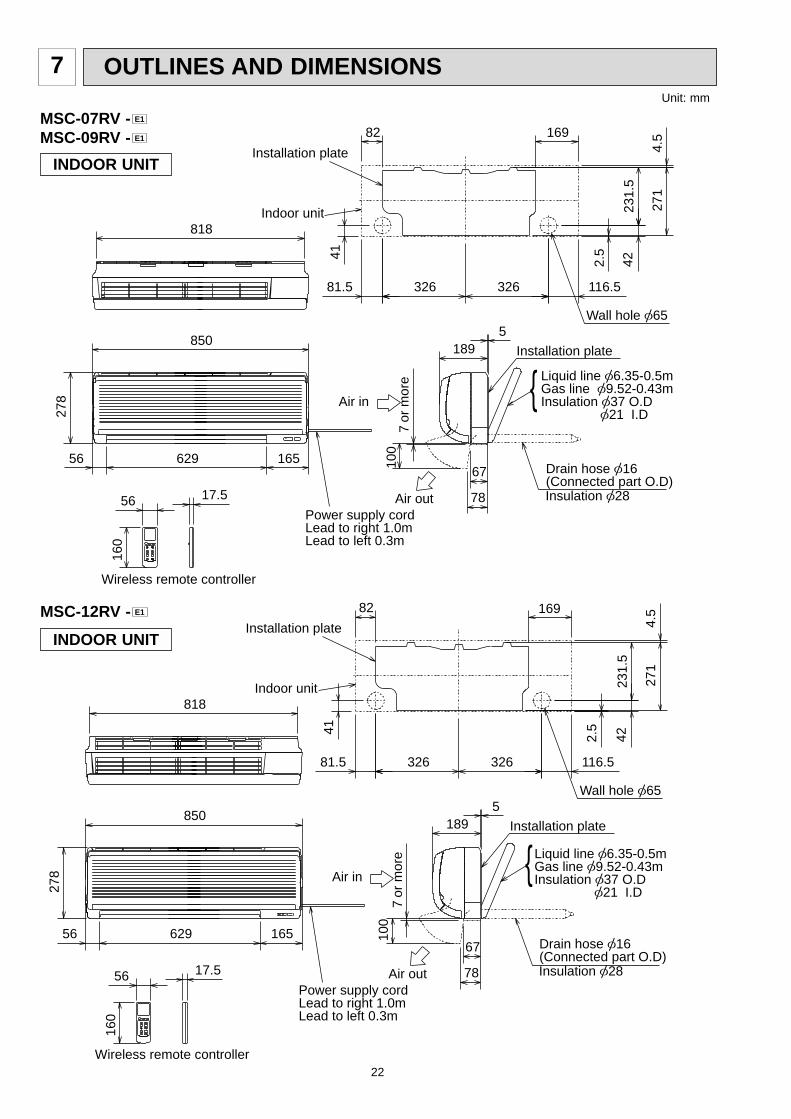
OUTLINES AND DIMENSIONS7
MSC-07RV -MSC-09RV - E1
E1
MSC-12RV - E1
INDOOR UNIT
INDOOR UNIT
116.581.5
78
67
818
850
16562956
7 or
mor
e10
0
41
2.5
42
271
4.5
231.
5
82 169
326 326
5189
56
160
17.5
Air in
Air out Insulation [28
Drain hose [16(Connected part O.D)
Installation plate
Wall hole [65
Indoor unit
Installation plate
Power supply cordLead to right 1.0mLead to left 0.3m
Wireless remote controller
Liquid line [6.35-0.5mGas line [9.52-0.43mInsulation [37 O.D
[21 I.D
278
116.581.5
818
278
850
16562956
or
mor
e10
0
41
2.5
42
271
4.5
231.
582 169
326 326
5189
56
160
17.5
Air in
Air out Insulation [28
Drain hose [16(Connected part O.D)
Installation plate
Wall hole [65
Indoor unit
Installation plate
Power supply cordLead to right 1.0mLead to left 0.3m
Wireless remote controller
Liquid line [6.35-0.5mGas line [9.52-0.43mInsulation [37 O.D
[21 I.D
78
67
7
Unit: mm

23
320
25
43- 35
-
155
90
10474
260
10
780500
12240
540
320
285
255
Service panel
Gas refrigerant pipe jointRefrigerant pipe(flared) [9.52 (MU-07/09RV)
(MUH-07/09RV)[12.7 (MU-12RV)
(MUH-12RV)
Liquid refrigerant pipe jointRefrigerant pipe(flared) [6.35
Air out
Air in
Air in
109
32
110147Drainage 3holes [33
If clearance behind the outdoorunits only 40B or 50Bside A must befully open.
10cm
or
mor
e
10cm or more
10cm or more
Outdoorunit
35cm or more
REQUIRED SPACE
A
40cm or more
Unit: mm
OUTDOOR UNIT
MU-07RV -MU-09RV -MU-12RV - E1
E1
E1 MUH-07RV -MUH-09RV -MUH-12RV - E1
E1
E1

24
230
260295
Bolt pitch4 holes 10 21
Bolt pitch for installation 500
250
1026
2.5
540
760112
Wiring hole Rear side
2063
384.
567
57
575757
68
68
Stop valve 1/4F
Stop valve 3/8F
151
Service panel
58
6021
3550
70
50
5056
105
Air in
Air in
Air out
Drainage
4 hole[16.2
108
ø415
35cm or more
50cmor more
10cm or more
10cm
or
mor
e
Unless any obstacleexists in front ,right Unless any obstacleexists in front and left sides.
10cm or more
Unless any obstacleexists in right , left andrear sides.
REQUIRED SPACE
Unit A
MUX10RV- E1
OUTDOOR UNIT
16 310 16
2905 30
605
292
20
500Bolt pitch for installation
50
90 5
7 5
7 5
7
Service port Stop valve3/8FA
154.6
Service portBC
Gas sideunion 3/8F
Liquid sideunion 1/4F
Stop valve 1/4F
30
52186
70 66Electrical wiring entrance (Rear) 15 25
Unless anyobstacle existsin right ,left , and rear sides.
C
B
Unless anyobstacle existsin front, rightand left sides.
REQUIRED SPACE
4 holes-10 21
3435
5480
236
91
51
168
57
850133
Air out
Air in
4 Drain holes [ 16.2
Air in 10cmor more
50cm or more
35cm or more
10cm or more
10cm
or
mor
e
A
MUX-18RV- E1
Unit: mm

25
MUX-24RV- E1
OUTDOOR UNIT
72.258.2
264.2
5050
5050
5050
50
64.8
2-U-Shape noched hols(Base bolt M10)
Wiring hole
2-Oval hols(12Å~36)(Base bolt M10)
Handle for moving
Gus pipe(flared ɔ12.7)
Liquid pipe(flared ɔ6.35)
Gus pipe(flared ɔ9.52)
Air in
Air out
Air in
Handle for moving
372
412
200 200500
5329
750
328900
27
34330
Unit: mm

26
Necessary surrounding clearance
Necessary surrounding clear-ance for concentrated installa-tion.
Leave overhead clearance fully
100
Handle formonving
200
1000
2957
23
Max
. 25
Base bolt length
To drain water in a mass, useoptional drain pan and drain socket.Drain pan : PAC-928DP,PAC-SA44DPDrain socket : PAC-SA46DS
Drain hole
Drain hole
(Base bolt M10)
(Base bolt M10)
2 Oval hols (12 13)
2-U-Shape noched hols
33
524
339
302
524
77
2
25
12
17
R6
40116
A
B
57
107
57
57
505
30 870
650
10
Max. 10 units
Air in
Air in
Air out
185 185500
362
10
10
500
500
10050
0
10
200
330
39.5
27.5
1715
Leave front clearance fully
Space for servicing
Leave overheadclearance fully
Rear pipinghole
Rearair-intake
Sideair-intake
Handle for moving
Handle for moving
Liquid pipe
(flared 6.35)
Groundterminal
Outlet guidemounting hole
Gas pipe
(flared 9.52)
MX
Z-18R
V-
E1
Unit: m
m
OU
TD
OO
R U
NIT
27
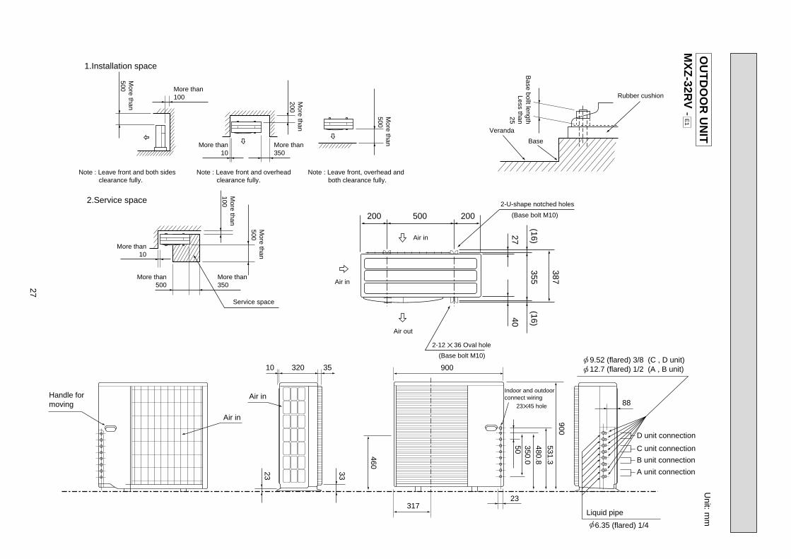
MX
Z-32R
V-
E1
1.Installation space
2.Service space
More than100 M
ore than200
More than
100
More than
500
More than
500
More than10
More than10
More than500
Base bollt length
Less than25More than350
More than350
Service space
Air in
2-U-shape notched holes
(Base bolt M10)
(Base bolt M10)
Air in
Air out
200 200
387
355
2740
(16)(16)
500
Veranda
Base
Rubber cushion
More than
500
Note : Leave front and both sides clearance fully.
Note : Leave front and overhead clearance fully.
Note : Leave front, overhead and both clearance fully.
2-12 36 Oval hole
23
10 35320 900
88
460
50
900
350.0480.8
531.3
31723
33
Handle formoving
Air in
Indoor and outdoorconnect wiringAir in
23 45 hole
D unit connection
C unit connection
B unit connection
A unit connection
6.35 (flared) 1/4
Liquid pipe
12.7 (flared) 1/2 (A , B unit) 9.52 (flared) 3/8 (C , D unit)[
[
[
Unit: m
mO
UT
DO
OR
UN
IT

28
WIRING DIAGRAM8
MSC-07RV -MSC-09RV -MSC-12RV - E1
E1
E1
MODELS WIRING DIAGRAM
SYMBOL
SR141
TB
SYMBOL
MV
NR11
RT11
RT12
SYMBOL
C11
F11
HIC1
MF
NAME NAME NAME
INDOOR FAN CAPACITOR
FUSE(3.15A)
DC/DC CONVERTER
INDOOR FAN MOTOR
VANE MOTOR
VARISTOR
ROOM TEMPERATURE THERMISTOR
INDOOR COIL THERMISTOR
SOLID STATE RELAY
TERMINAL BLOCK
CIRCUIT BREAKER
SR141C11
RED
WHT
3
65
BRN
YLW
GRYBLK
4321
MF121CN
123
111CN
112CN RT12
RT11
NR11
HIC1
TRANS
F11
ELECTRONIC CONTROL P.C. BOARD
CN211
TAB12
CN201321
CN20221
LD101T151CN
55
BRN
RED
BLU
WHT
BLK
BLU
BRN
TBL
3
N
2
1
12V
TO OUTDOORUNITCONNECTING
POWERSUPPLYCORD~/N 220-240V50Hz
GRN
/YLW
POWER MONITOR,RECEIVERP.C.BOARD
REMOTECONTROLLER
MV
FORMUH ORMXZ TYPE
FORMU ORMUX TYPE
12V
PE
INDOOR UNIT
NOTE:1. About the outdoor side electric wiring refer to the outdoor unit electric wiring diagram for servicing.2. Use copper conductors only. (For field wiring)3. Symbols below indicate./: Terminal block, : Connector
29
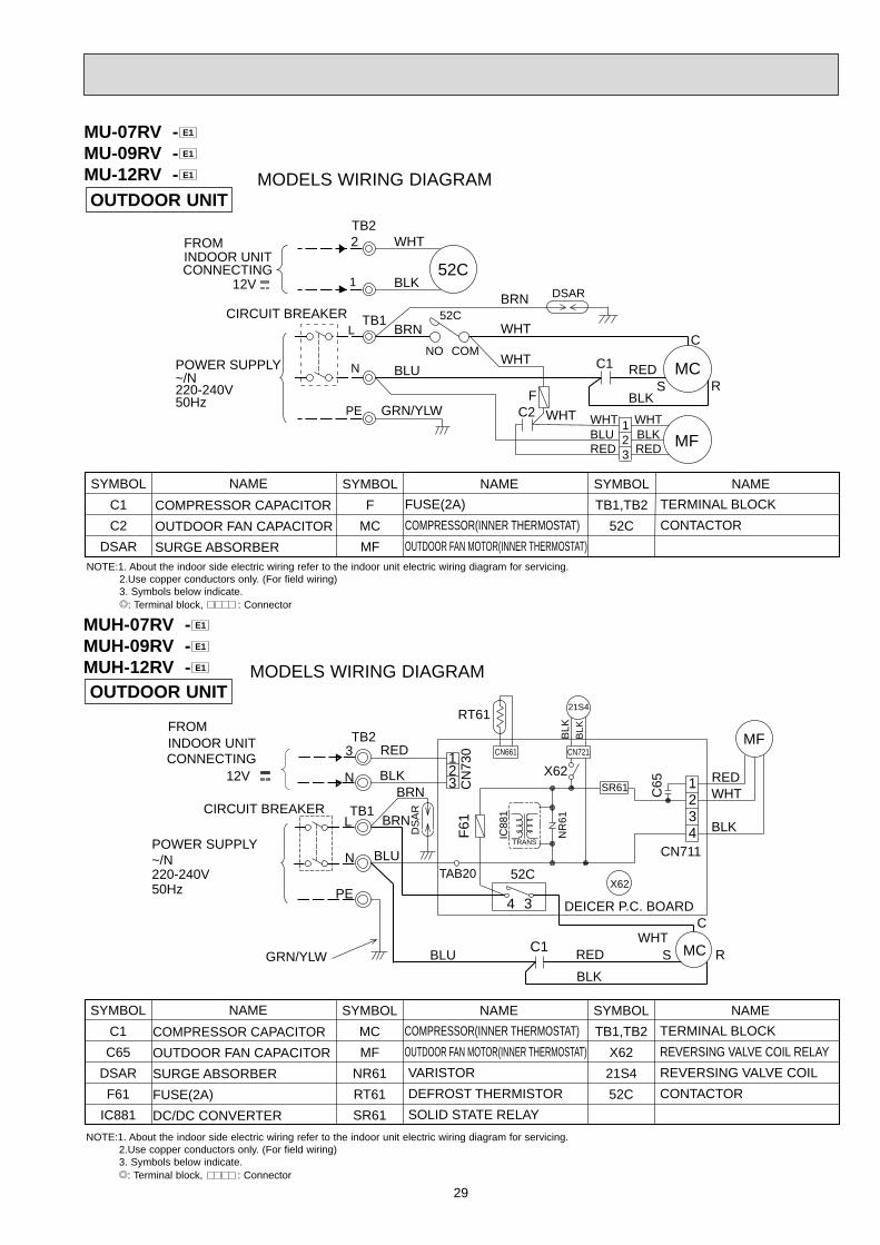
MODELS WIRING DIAGRAMOUTDOOR UNIT
SYMBOL
TB1,TB2
X62
21S4
52C
SYMBOL
MC
MF
NR61
RT61
SR61
SYMBOL
C1
C65
DSAR
F61
IC881
NAME NAME NAME
COMPRESSOR CAPACITOR
OUTDOOR FAN CAPACITOR
SURGE ABSORBER
FUSE(2A)
DC/DC CONVERTER
COMPRESSOR(INNER THERMOSTAT)
OUTDOOR FAN MOTOR(INNER THERMOSTAT)
VARISTOR
DEFROST THERMISTOR
SOLID STATE RELAY
TERMINAL BLOCK
REVERSING VALVE COIL RELAY
REVERSING VALVE COIL
CONTACTOR
CIRCUIT BREAKER
POWER SUPPLY~/N 220-240V50Hz
12V
34
WHT
BLK
RED
MF
N
4321
RT61
CN
730
F61
SR61
GRN/YLW
3
RS
CWHT
RED
BLK
BLUC1
52C
MC
21S4
321
BLK
BLK
CN721
X62
C65
TAB20
CN661
BLU CN711
DEICER P.C. BOARD
BRN
BLK
RED
DS
AR
BRN
TB2
N
FROMINDOOR UNITCONNECTING
TB1
PE
L
IC88
1
TRANS
X62
NR
61
MUH-07RV -MUH-09RV -MUH-12RV - E1
E1
E1
MODELS WIRING DIAGRAMOUTDOOR UNIT
MU-07RV -MU-09RV -MU-12RV - E1
E1
E1
NOTE:1. About the indoor side electric wiring refer to the indoor unit electric wiring diagram for servicing.2.Use copper conductors only. (For field wiring)3. Symbols below indicate./: Terminal block, : Connector
NOTE:1. About the indoor side electric wiring refer to the indoor unit electric wiring diagram for servicing.2.Use copper conductors only. (For field wiring)3. Symbols below indicate./: Terminal block, : Connector
CIRCUIT BREAKER
POWER SUPPLY~/N 220-240V50Hz
12V
GRN/YLW
TB2
RED
WHTBLK
WHTBLU
321
RED MF
C2
MCC1
S R
C
N
2FROMINDOOR UNITCONNECTING
WHT
BLU
BLK
REDWHT
52C
TB1
WHT
BLK
WHT
52C
PE
L
1
NO COM
DSARBRN
F
BRN
SYMBOL
TB1,TB2
52C
SYMBOL
F
MC
MF
SYMBOL
C1
C2
DSAR
NAME NAME NAME
COMPRESSOR CAPACITOR
OUTDOOR FAN CAPACITOR
SURGE ABSORBER
FUSE(2A)
COMPRESSOR(INNER THERMOSTAT)
OUTDOOR FAN MOTOR(INNER THERMOSTAT)
TERMINAL BLOCK
CONTACTOR

30
OUTDOOR UNIT
NOTE:1. About the indoor side electric wiring refer to the indoor unit electric wiring diagram for servicing.2.Use copper conductors only. (For field wiring)
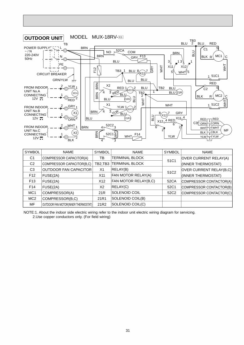
MODEL MUX-10RV- E1
PE
WHT WHT
BR
NF13
F12
CIRCUIT BREAKER
WH
T
1
TB2
2
TB2
TB31
BLU
BLU
BLK
RED
C2
2
2
1
1
4 3
X1
4
X2
3
BLUBLU
BLUBLU
RED
YLW
RED
YLW
BLUB
RN
BLU
BLU
BLUBRN
WH
T
BR
N
WHT WHTBRN
NO COM
52C1
NO52C2
COM
3
1
RED
BLU
RED
BLK
21R2
21R1
21R
52C1TB
52C2MF
WHT
2
WHT
1 51C
RS MC
C
X2
N
LPOWER SUPPLY~ / N220-240V50Hz
TB
GR
N/Y
LW
BLK
2
2
1
1WHT
ORN
GRY
FROM INDOORUNIT No.ACONNECTING
12V
X1
1
2
1
2
FROM INDOORUNIT No.BCONNECTING
12V
2TB3
C1
SYMBOL
51C
52C1
51C2
SYMBOL
TB1,TB2,TB3
X1
X2
21R
21R1
21R2
SYMBOL
C1
C2
F12
F13
MC
MF
NAME NAME NAME
COMPRESSOR CAPACITOR
OUTDOOR FAN CAPACITOR
FUSE(2A)
FUSE(2A)
COMPRESSOR
OUTDOOR FAN MOTOR
TERMINAL BLOCK
RELAY(A)
RELAY(B)
BYPASS VALVE SOLENOID COIL
SOLENOID COIL(A)
SOLENOID COIL(B)
OVERCURRENT RELAY
(INNER THERMOSTAT)
COMPRESSOR CONTACTOR(A)
COMPRESSOR CONTACTOR(B)
31
FROM INDOORUNIT No.BCONNECTING
12V
PE
BR
N
WH
T
F14
BLU
GRY F13
CIRCUIT BREAKER
YLW
RED
BRN
BLU
BLU
BLU
WHT
F12
BLU
BLU
BLU GR
Y
1TB3
TB2 1
4 3
4 3
2
2
1
1
BLU
BLU
BLU
YLW
GRN/YLW
BLK
WHT
ORN
GRY
RED
YLW
2
1
51C2
BRN
YLW
BR
N
BLU
WH
T
WH
TW
HT
RED
REDBLU
WHT
BRN
FROM INDOORUNIT No.ACONNECTING
12V
2TB3
TB2
X2
X1
1
2
1
2
C2
C1
R C
S
CR
S
MC2BLK52CA
FROM INDOORUNIT No.CCONNECTING
12VB
LU
52C2
21R2
RED 21X2
X1
COMNO 52CA
3
X12
5
1
MF
MC1
51C11
1
BLK
ORN
WHT
YLW
RED
BLK
52C1
X11
X11
21R
X11X12
21R1X12
C3
TB
52C1
52C2
POWER SUPPLY~ / N220-240V50Hz
1
2
54
23
1
L
N
478
4
62
62
2
8 7
3 1
5
3
21
4
4 3
BRN
BLU
BRN
BR
N
WHT
RED
GRY
WHT
BLUBLU
YLW
BLK
WHT
ORN
RED
OUTDOOR UNIT MODEL MUX-18RV- E1
NOTE:1. About the indoor side electric wiring refer to the indoor unit electric wiring diagram for servicing.2.Use copper conductors only. (For field wiring)
SYMBOL
51C1
51C2
52CA
52C1
52C2
SYMBOL
TB
TB2,TB3
X1
X11
X12
X2
21R
21R1
21R2
SYMBOL
C1
C2
C3
F12
F13
F14
MC1
MC2
MF
NAME NAME NAME
COMPRESSOR CAPACITOR(A)
COMPRESSOR CAPACITOR(B,C)
OUTDOOR FAN CAPACITOR
FUSE(2A)
FUSE(2A)
FUSE(2A)
COMPRESSOR(A)
COMPRESSOR(B,C)
OUTDOOR FAN MOTOR(INNER THERMOSTAT)
TERMINAL BLOCK
TERMINAL BLOCK
RELAY(B)
FAN MOTOR RELAY(A)
FAN MOTOR RELAY(B,C)
RELAY(C)
SOLENOID COIL
SOLENOID COIL(B)
SOLENOID COIL(C)
OVER CURRENT RELAY(A)
(INNER THERMOSTAT)
OVER CURRENT RELAY(B,C)
(INNER THERMOSTAT)
COMPRESSOR CONTACTOR(A)
COMPRESSOR CONTACTOR(B)
COMPRESSOR CONTACTOR(C)

32
MODEL MUX-24RV- E1
PE
1B
LU
WHT
WHT
BR
N
BRN
BRNBRN
BLU
BLU
BLU
WHT
WHT
WHT
2
1
TB9
TB8
12
1
BR
N
TB10
2
BRN
BRN
BLU
BLK
REDWHT
WHT
BLK
RED
C
MC1
RSC1
6
WHT
21
21
21
BLU
8
7
87
BLU
BLUBLU
BLU
21RB
321
BLUBLU
2 1
BLU
1 2
BLU ORN BLU52C4
21R4
32
BLUBLUBLU
1
3
BLU
21R3BLU
BLUBLU
21
ORN 52C2BLU
21R2 BLUBLU
21
BLU
21
BLU
BLU
WH
T
BLU
12
2
1
2
TB6
TB5TB7
BLU
ORN
BLU
BLU
BR
NB
RN
BR
NB
RN
BR
N
BLU
BLU
C11
WHT
ORN
ORN
BLU
BLU
BLU
BLU
BRN
TB4
TB3
TB2
TB1
BREAKER
2
1 X1
FROM INDOORUNIT No.ACONNECTING 12V
2
1
YLW
YLW
X12
X11
21RA
52C3
52C1
21R1
34
X4
34
X3
34
X2
34
X1
34
4 352C4
52C3
GRYORNWHTYLW
34
4 3
5
13
N
L
1
32
45
2
1
POWER SUPPLY~/N220-240V50Hz
52C1
52C2
TB
X11
BLK
RED
WHTORN
MF
1
5X12
3
FROM INDOORUNIT No.DCONNECTING 12V
X2
MC2
C
RSC2
2
1
2
1
X3
X4
FROM INDOORUNIT No.CCONNECTING 12V
FROM INDOORUNIT No.BCONNECTING 12V
2
1
ORN
ORN
WHT
WHT
GRY
GRY
GRN/YLW
2
2
1
1
FCIRCUIT
OUTDOOR UNIT
NOTE:1. About the indoor side electric wiring refer to the indoor unit electric wiring diagram for servicing.2.Use copper conductors only. (For field wiring)
SYMBOL
52C3
52C4
21R1
21R2
21R3
21R4
21RA
21RB
SYMBOL
TB
TB1~TB10
X1
X2
X3
X4
X11
X12
52C1
52C2
SYMBOL
C1
C2
C11
F
MC1
MC2
MF
NAME NAME NAME
COMPRESSOR CAPACITOR(A,B)
OUTDOOR FAN CAPACITOR(C,D)
OUTDOOR FAN CAPACITOR
FUSE(3.15A)
COMPRESSOR(A,B)
(INNER THERMOSTAT)
COMPRESSOR(C,D)
(INNER THERMOSTAT)
OUTDOOR FAN MOTOR
(INNER THERMOSTAT)
TERMINAL BLOCK
TERMINAL BLOCK
RELAY(A)
RELAY(B)
RELAY(C)
RELAY(D)
FAN MORTOR RELAY(A,B)
FAN MORTOR RELAY(B,C)
COMPRESSOR RELAY(A)
COMPRESSOR RELAY(B)
COMPRESSOR RELAY(C)
COMPRESSOR RELAY(D)
SOLENOID COIL(A)
SOLENOID COIL(B)
SOLENOID COIL(C)
SOLENOID COIL(D)
SOLENOID COIL
SOLENOID COIL

33
CIRCUIT BREAKER
T80
1
RT64 RT65
TB
FROMINDOORUNIT CONNECTING
12VDS61
NF61
INDOORUNIT (A)
POWER SUPPLY220-240V~ / N50Hz
INDOORUNIT (B)
TBNF62
C61
C64C63
L61
L
DS63
C67
SSR61
C65X67
X60
MFMC
TRR65
21S4
R64
X64CT61
NR61AR61
ELECTRONIC CONTROL P.C.BOARD
LEV A LEV BRELAY P.C.BOARD
RT66 RT67 RT61 HPSRT62 RT63
PE
65
6
1 2 3 454321 54321 6 321 1 2 1 2
1 2 1 2
234
1
234
1N
3
N
3
L
N
2 4 3 2 1 8
V
WU
7654321
WVUP
N
2 3 4 5111234
1 2 3 4 1234
321
LDE
1LD
62
FUSE2
F62
FUSE1
TAB91
CN683
3
4
1 ~
+
-
~
+~~~
-
+ -
2
CN61CN63
CN
701
EwNBwNEvNBvNEuNBuN
EwPBwPEvPBvPEuPBuP
CN671CN641CN681CN661CN682
CN731CN621CN801
LD77
LD74
LD73LD71
LD72
3
42
1
+
-
TB
62
TB
61
LD61
3 4LD
63
LD64
CN
941
CN771CN761CN
601
CN
611
TB
AC
1T
BA
C2
RE
D
RE
D
BRN
BLK
WH
TO
RN
GRY
GRY
GRY
GRY
GRN/YLW
BLURED
BLU
BLU
RED
BLU
BLU
BLU
ORN
YLW
WHT
RED
BLK
BLK
BLK
BLK
GRY
GRY
GRY
GRY
BLU
RE
D
BLK
WHT
WH
TB
LK RED
GRY
GRY
RED
RED
GRN
YLW
RED
BLU
BLK
WH
T
BLU
RED
BLK BLU
RED
ORN RE
D
BLK
BLU
WHT WHT
BLU
GRN
YLW
ORN
RED
BRN
REDWHTBLK
REDWHTBLK
YLW
RE
D
BRNRED
ORNYLW
GRNBLU
BLU
ORN
YLW
WHT
RED
GRN
BLK
BLU
BR
N
BLK
YLWBRN
RED
YLWYLW
BLU
RED
BRN
RED
MO
DE
LS M
XZ
-18RV
- E
1
NOTE:1. About the indoor side electric wiring refer to the indoor unit electric wiring diagram for servicing.2.Use copper conductors only. (For field wiring)
SYMBOL
RT63
RT64
RT65
RT66
RT67
R64
SYMBOL
L
LEV A,B
L61
MC
MF
NF61,62
NR61
RT61
RT62
SYMBOL
AR61
CT61
C61
C63
C64
C65
C67
DS61,63
FUSE1
FUSE2
F62
HPS
NAME NAME NAME
SURGE ABSORBER
CURRENT TRANSFORMER
POWER-FACTOR CAPACITOR
CERAMIC CAPACITOR
CERAMIC CAPACITOR
INDOOR FAN CAPACITOR
SMOOTHING CAPACITOR
DIODE MODULE
FUSE(1A)
FUSE(3.15A)
FUSE(3.15A)
HIGH PRESSURE SWITCH
REACTOR
EXPANSION VALVE
CMC COIL
COMPRESSOR
INDOOR FAN MOTOR
(INNER THERMOSTAT)
NOISE FILTER
VARISTOR
DEFROST TEMPERATURE
THERMISTOR
DISCHARGE TEMPERATURE
THERMISTOR
FIN TEMPERATURE
THERMISTOR
GAS PIPE TEMPERATURE B.
THERMISTOR
GAS PIPE TEMPERATURE A.
THERMISTOR
SUCTION TEMPERATURE
THERMISTOR
EVAPORATION TEMPERATURE
THERMISTOR
CURRENT-LIMITING
RESISTOR
SYMBOL
R65
SSR61
TB
TR
T801
X60,67
X64
21S4
NAME
CURRENT-DETECTING
RESISTOR
SOLID STATE RELAY
TERMINAL BLOCK
POWER TRANSISTOR
MODULE
TRANSFORMER
FAN MOTOR RELAY
RELAY
REVERSING VALVE
SOLENOID COIL
OU
TD
OO
R U
NIT

34
POWER SUPPLY~/N 220-240V 50Hz
INDOORUNIT (A)
CIRCUIT BRAKER
TB2
TB3BLURED
TB4
X64
GRN/YLW
GRN/YLW
CN720
CN
601
0
4X64
LD62
CN913
CN791
CN901
6 4
2
CN902
CN851 CN852
MF61CH
21S4 21S2
1 2 1 2
21
21
1 2
12
3 4
1 2 3 4 5 6
12
34
56
7
1 2 3 4 5 6
CN912
C65
LD63
LD64
LDB
LDB
LD61
LDE
L61
F911
SS
R61
SS
R62
SS
R63 X
63
X62
X611
6
L
N
3
N
INDOORUNIT (B)
BLUORN
CN
602
12
3
3
3
N
INDOORUNIT (C)
BLUYLW
CN
603
12N
INDOORUNIT (D)
BLUBRN
CN
604
12N
BLK
BR
N
GR
Y
BLK
BLK WHT
YLW
RE
D
RE
D
RE
DB
RN
BLU
OR
NY
LWW
HT
OR
NW
HT
BLK
BLU
YLW
RE
DB
LU BLU
WH
T
WH
T
ORN ORN RED RED
YLW
YLW
YLW
BLK
BLK
ORN
ORN
BRN
GRY X65
X66
X67
X67
63H2
X65
X66
CN
552 C
N553
BLK
RELAYP.C. BOARD
WH
T
WH
T
RE
D
WH
T
V
U W
YLW
AK
L
WHT
NOISE FILTERP.C.BOARD
REDDS61
DS62
C61
CT61
C63 C62+ +
-
+
-
+
--
BLKREDR
BLU
LEV A
CN7921 2 3 4 5 6
RE
DB
RN
BLU
OR
NY
LWW
HT
LEV B
CN7931 2 3 4 5 6
RE
DB
RN
BLU
OR
NY
LWW
HT
LEV C
CN794 CN722 CN663
63H1 RT63
1 2 3 4 5 6CN662
1 2 3 4 5 6 7 81 2 1 2
12
3
3 4
RE
D
RE
DR
ED
63L
BLK
BLK
BLK
BLK
RT66 RT68
RT67 RT69
GR
YG
RY
GR
YG
RY
GR
YG
RY
GR
YG
RY
CN661
CN
705
76
54
32
1C
N51
5
12
34
43
21C
N801 C
N50
1
TA
B62
TA
B63
T801
CT62
TAB66
TAB65
TAB64
I.P.M P.C. BOARD
F80
1(1
A)
CN
704 CN
514
CN
554
CN
551
CN
723
1 2 3 4 5 6 7 8
RT62 RT64
RT61 RT65
GR
YG
RY
BLK
BLK
GR
YG
RY
GR
YG
RY
BR
NB
LUO
RN
YLW
WH
TLEV D
ELECTRONIC CONTROL P.C. BOARD
MCPE
FR
OM
IND
OO
R U
NIT
C
ON
NE
CT
ING
12V
SYMBOLC61
C62,63C65CH
CT61,62DS61DS62F801F911
LL61
LEV A~D
SYMBOLMC
MF61R
RT61RT62RT63RT64RT65
RT66,67RT68,69
SSR61,62SSR63
NAMEPOWER FACTOR CAPACITORSMOOTHING CAPACITOROUTDOOR FAN CAPACITORCRANKCASE HEATERCURRENT TRANSFORMERDIODE MODULEDIODE STACKFUSE (1A)FUSE (1A)REACTORCOMMON MODE CHOKE COILEXPANSION VALVE
NAMECOMPRESSOROUTDOOR FAN MOTOR (INNER FUSE)RESISTORDISCHARGE TEMPERATURE THERMISTORDEFROST TEMPERATURE THERMISTORFIN TEMPERATURE THERMISTOREVAPORATION TEMPERATURE THERMISTORSUCTION TEMPERATURE THERMISTORGUS PIPE TEMPERATURE THERMISTORGUS PIPE TEMPERATURE THERMISTORSOLENOID COIL RELAYCRANKCASE HEATER RELAY
SYMBOLT801
TB2,3,4X61,62,63
X64,65X66,6721S221S463H163H263L
NAMETRANSFORMERTERMINAL BLOCKFAN MOTOR RELAYRELAYRELAYSOLENOID COILR.V. COILHIGH PRESSURE SWITCHHIGH PRESSURE SWITCHLOW PRESSURE SWITCH
NOTE:1. About the indoor side electric wiring refer to the indoor unit electric wiring diagram for servicing.2.Use copper conductors only. (For field wiring)
MO
DE
LS M
XZ
-32RV
- E
1O
UT
DO
OR
UN
IT

35
REFRIGERANT SYSTEM DIAGRAM9
MSC-07RV -MSC-09RV - E1
E1 MU-07RV -MU-09RV - E1
E1
MSC-12RV - E1 MU-12RV - E1
INDOOR UNIT
INDOOR UNIT
OUTDOOR UNIT
OUTDOOR UNIT
Indoorheatexchanger
Room temperaturethermistorRT11
Refrigerant pipe [9.52(Option)(with heat insulator)
Outdoorheatexchanger
Capillary tube[3.0x[1.4x600
Strainer
Refrigerant pipe [6.35(Option)(with heat insulator)
Refrigerant flow in cooling
Unit:mm
Unit:mm
Refrigerant pipe [12.7(Option)(with heat insulator)
Stop valve(with service port)
Stop valve(with service port)
Strainer
Refrigerant pipe [6.35(Option)(with heat insulator)
Stop valve
Capillary tube[3.0x[1.6x600
Refrigerant flow in cooling
Outdoorheatexchanger
Room temperaturethermistorRT11
Indoor coilthermistorRT12
Indoor coilthermistor
RT12
Compressor
Indoorheatexchanger
Compressor
Flared connection
Flared connection
Flared connection
Flared connection

36
Unit:mm
MSC-12RV - E1 MUH-12RV - E1
INDOOR UNIT OUTDOOR UNIT
(with heat insulator)
(with heat insulator)
Refrigerant pipe [12.7(Option)
Reversing valve
Muffler
Stop valve(with service port)
Strainer
Refrigerant pipe [6.35(Option)
Stop valve
Capillary tube[3.0x[1.6x700
Checkvalve
Refrigerant flow in cooling
Refrigerant flow in heating
DefrostthermistorRT61
Outdoorheatexchanger
Room temperaturethermistorRT11
Indoor coilthermistorRT12
Capillary tube[3.0x[1.8x300
Flared connection
Flared connection
Compressor
Indoorheatexchanger
Accumulator
Reversing valve coilheating ONcooling OFF
MSC-07RV -MSC-09RV - E1
E1 MUH-07RV -MUH-09RV - E1
E1
INDOOR UNIT OUTDOOR UNIT
Indoorheatexchanger
Room temperaturethermistorRT11
(with heat insulator)
Refrigerant pipe [ 9.52(Option)
Muffler
Reversing valve
DefrostthermistorRT61
Accumulator
Strainer
Outdoorheatexchanger
Capillary tube[3.0x[1.4x800
(2 pcs)
Capillary tube[3.0x[1.6x600(MUH-07RV)[3.0x[1.6x400(MUH-09RV)
Capillary tube[3.0x[1.4x600(MUH-07RV)[3.0x[1.4x550(MUH-09RV)
Check valve
Strainer
Refrigerant pipe [6.35 (Option)(with heat insulator)
Refrigerant flow in cooling
Refrigerant flow in heating
Unit:mm
Stop valve(with serviceport)
Indoor coilthermistorRT12
Reversing valve coilheating ONcooling OFF
Capillary tube[3.0x[1.4x500(2pcs)
Flared connection
Flared connection
Compressor
Stop valve
Strainer

37
Piping size O.D : mm Length of connecting pipe : mModels
Piping size O.D : mm Length of connecting pipe : mModels
Refrigerant piping
Max. length : m
A
10
15
Indoor unit
Gas 0.43
Liquid 0.5
Gas
9.52
12.7
Liquid
6.35
Outdoor unit
Gas 0
Liquid 0
MSC-07RV - E1
MUH-07RV - E1
MSC-09RV - E1 MUH-09RV - E1
MSC-12RV - E1
MUH-12RV - E1
Refrigerant piping
Max. length : m
A
10
15
Indoor unit
Gas 0.43
Liquid 0.5
Gas
9.52
12.7
Liquid
6.35
Outdoor unit
Gas 0
Liquid 0
MSC-07RV - E1
MU-07RV - E1
MSC-09RV - E1
MU-09RV - E1
MSC-12RV - E1
MU-12RV - E1
Indoor unit
w Max. Heightdifference 5m
Height difference should be within 5m regardless of which unit, indoor or outdoor position is high.
Outdoor unit
Refrigerant Piping Max.length
A
Models Refrigerant piping length (one way)
Models Refrigerant piping length (one way)
Outdoor unit precharged
800
1190
15m
400
7m
0
10m
150
MSC-07RV - E1
MUH-07RV - E1
MSC-09RV - E1 MUH-09RV - E1
MSC-12RV - E1
MUH-12RV - E1
Calculation : Xg=50g/m 5 x(A-7)m
Outdoor unit precharged
800
850
880
15m
120
7m
0
10m
45
MSC-07RV - E1
MU-07RV - E1
MSC-09RV - E1
MU-09RV - E1
MSC-12RV - E1
MU-12RV - E1
Calculation : Xg=15g/m x(A-7)m
MAX. HEIGHT DIFFERENCE
ADDITIONAL REFRIGERANT CHARGE(R-22 : g)
MAX. REFRIGERANT PIPING LENGTH
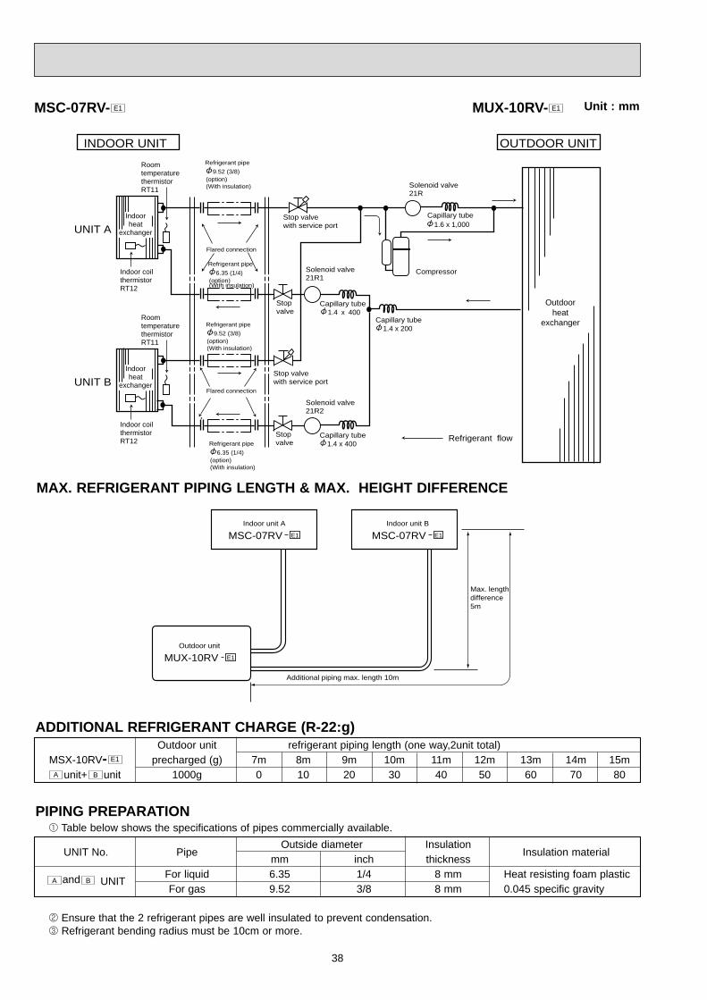
38
MSC-07RVIndoor unit A
E1
MUX-10RVOutdoor unit
Additional piping max. length 10m
Max. lengthdifference5m
E1
MSC-07RVIndoor unit B
E1
OUTDOOR UNITINDOOR UNIT
UNIT AIndoorheat
exchanger
Indoor coilthermistorRT12
RoomtemperaturethermistorRT11
UNIT BIndoorheat
exchanger
Outdoorheat
exchanger
Indoor coilthermistorRT12
RoomtemperaturethermistorRT11
(option)(With insulation)
Refrigerant pipe
9.52 (3/8)
(option)(With insulation)
Refrigerant pipe
9.52 (3/8)
Flared connection
(option)(With insulation)
Refrigerant pipe
6.35 (1/4)
(option)(With insulation)
Refrigerant pipe
6.35 (1/4)
Flared connection
Stop valve with service port
Solenoid valve 21R1
Solenoid valve 21R
Solenoid valve 21R2
Capillary tube1.4 x 400
Capillary tube1.4 x 400
Capillary tube
Capillary tube
1.4 x 200
1.6 x 1,000
Compressor
Refrigerant flow
Stop valve with service port
Stop valve
Stop valve
MSC-07RV- E1
MAX. REFRIGERANT PIPING LENGTH & MAX. HEIGHT DIFFERENCE
ADDITIONAL REFRIGERANT CHARGE (R-22:g)
PIPING PREPARATION1 Table below shows the specifications of pipes commercially available.
2 Ensure that the 2 refrigerant pipes are well insulated to prevent condensation.3 Refrigerant bending radius must be 10cm or more.
MUX-10RV- E1 Unit : mm
Outdoor unit refrigerant piping length (one way,2unit total)MSX-10RV- precharged (g) 7m 8m 9m 10m 11m 12m 13m 14m 15m
unit+ unit 1000g 0 10 20 30 40 50 60 70 80
E1
Outside diameter InsulationUNIT No. Pipe
mm inch thicknessInsulation material
and UNITFor liquid 6.35 1/4 8 mm Heat resisting foam plasticFor gas 9.52 3/8 8 mm 0.045 specific gravity
BA
A B

39
OUTDOOR UNITINDOOR UNIT
UNIT AIndoorheat
exchanger
Indoor coilthermistorRT12
RoomtemperaturethermistorRT11
UNIT BIndoorheat
exchanger
Outdoorheat
exchanger
Indoor coilthermistorRT12
RoomtemperaturethermistorRT11
(option)(With insulation)
Refrigerant pipe
9.52<3/8>
(option)(With insulation)
Refrigerant pipe 9.52<3/8>
(option)(With insulation)
Refrigerant pipe6.35<1/4>
Flared connection
(option)(With insulation)
Refrigerant pipe
6.35<1/4>
Flared connection
Refrigerant pipe 9.52<3/8>
(option)(With insulation)
Refrigerant pipe
6.35<1/4>
Flared connection
Stop valve with service port
Stop valve
Solenoid valve 21R1
Solenoid valve 21R1
Solenoid valve 21R
Stop valve with service port
Stop valve with service port
Capillary tube1.4 1100
Capillary tube1.6 1100
Capillary tube1.6 1100
Capillary tube1.6 300
Capillary tube1.6 1,000
Compressor(A)
Compressor(B,C)
Refrigerant flow
MSC-09RV E1
MSC-09RV E1
UNIT CIndoorheat
exchanger
Indoor coilthermistorRT12
RoomtemperaturethermistorRT11
MSC-09RV E1
MSC-09RV- E1 MUX-18RV- E1
Unit : mm

40
LA
Indoor unit AMSC-09RV - E1
H LB H LC
H
Indoor unit BMSC-09RV - E1
Indoor unit CMSC-09RV - E1
Outdoor unit MUX-18RV - E1
UNIT No.Insulationthickness
Pipe
For liquid
For gas
Outside diameter
mm inch
6.35 1/4
9.52 3/8
8mm
8mm
, and
unitC
BA
Insulation material
Heat resisting foam plastic0.045 specific gravity
Outdoor unitprecharged
750g
Refrigerant piping length (one way)
7m 8m 9m 10m
0 15 30 45
unit + unitCB
Outdoor unitprecharged
750g
Refrigerant piping length (one way,2 unit total)
7m
0
8m
15
9m
30
10m
45
11m
60
12m
75
13m
90
14m
105
15m
120
MSX-18RV- E1
ADDITIONAL REFRIGERANT CHARGE (R-22:g)
Max.limits
UNIT No.
A
B
C
Pipe length
10m
10m Total15m
LB+
LC10m
LA
LB
LC
Height difference (H)
5m
5m
5m
No. of bends
10
10 Total1510
PIPING PREPARATION1Table below shows the specifications of pipes commercially available.
2Ensure that the 2 refrigerant pipes are well insulated to prevent condensation.3Refrigerant bending radius must be 10cm or more.
MAX.REFRIGERANT PIPING LENGTH & MAX. HEIGHT DIFFERENCE
unitA
Note: The length of piping to individual units (A,B,C) should not exceed 10 meters.If units B and C are linked, the maximum combined length of piping should not exceed 15 meters.

41
MSC-09RV-MSC-12RV- E1
E1 MUX-24RV- E1 Unit : mm
OUTDOOR UNITINDOOR UNIT
UNIT AIndoorheat
exchanger
Indoor coilthermistorRT12
RoomtemperaturethermistorRT11
UNIT BIndoorheat
exchanger
Outdoorheat
exchanger
Indoor coilthermistorRT12
RoomtemperaturethermistorRT11
(option)(With insulation)
Refrigerant pipe
12.7 (1/2)
(option)(With insulation)
Refrigerant pipe
12.7 (1/2)
Flared connection
(option)(With insulation)
Refrigerant pipe6.35 (1/4)
(option)(With insulation)
Refrigerant pipe
6.35 (1/4)
Flared connection
Stop valve with service port
Solenoid valve 21R1
Solenoid valve 21RA
Solenoid valve 21R2
Capillary tube1.6 x 420
Capillary tube1.6 x 420
Capillary tube
Capillary tube
1.8 x 260
1.6 x 1,000
Compressor 1
Refrigerant flow
Stop valve with service port
Stop valve
Stop valve
UNIT CIndoorheat
exchanger
Indoor coilthermistorRT12
RoomtemperaturethermistorRT11
UNIT DIndoorheat
exchanger
Indoor coilthermistorRT12
RoomtemperaturethermistorRT11
(option)(With insulation)
Refrigerant pipe
9.52 (3/8)
(option)(With insulation)
Refrigerant pipe
9.52 (3/8)
Flared connection
(option)(With insulation)
Refrigerant pipe6.35 (1/4)
(option)(With insulation)
Refrigerant pipe
6.35 (1/4)
Flared connection
Stop valve with service port
Solenoid valve 21R3
Solenoid valve 21RB
Solenoid valve 21R4
Capillary tube1.6 x 650
Capillary tube1.6 x 650
Capillary tube
Capillary tube
1.6 x 400
1.6 x 1,000
Compressor 2
Stop valve with service port
Stop valve
Stop valve
MSC-12RV- E1
MSC-12RV- E1
MSC-09RV- E1
MSC-09RV- E1

42
UNIT No.Insulationthickness
Pipe
For liquid
For gas
For liquid
For gas
Outside diameter
mm inch
6.35 1/4
12.7
6.35
9.52
1/2
1/4
3/8
8mm
8mm
8mm
8mm
Insulation material
Heat resisting foam plastic0.045 specific gravity
MSX-24RV- E1
ADDITIONAL REFRIGERANT CHARGE (R-22g)
Max.limits
UNIT No.
A
B
C
D
Pipe length
20m
20m
Total30m
Total30m
LC+
LD
LA+
LB
20m
20m
LA
LB
LC
LD
Height difference (H)
10m
10m
10m
10m
No. of bends
10
10
Total15
Total15
10
10
PIPING PREPARATION
MAX.REFRIGERANT PIPING LENGTH & MAX. HEIGHT DIFFERENCE
Note: The length of individual units (A,B,C,D) should not exceed 20 meters.If units A and B or C and D are linked, the maximum combined length of piping should not exceed 30 meters.
Outdoor unitprecharged
(g)
1000g
1000g
Refrigerant piping length (one way, 2 unit total)
10m
11m
12m
13m
14m
15m
16m
17m
18m
19m
20m
21m
22m
23m
24m
25m
26m
27m
28m
29m
30m
0 10 20 30 40 50 60 70 80 90 100 110 120 130 140 150 160 170 180 190 200
0
unit + unitBA
and unitBA
and unitDC
UNIT No.
unit + unitDC
Outdoor unit
MUX-24RV- E1
Indoor unit A
MSC-12RV- E1
Indoor unit B
MSC-12RV- E1
Indoor unit C
MSC-09RV- E1
Indoor unit D
MSC-09RV- E1
HLDHLCHLBHLA
10 20 30 40 50 60 70 80 90 100 110 120 130 140 150 160 170 180 190 200

43
9.52
6.35
9.52
9.52
2.0X 0.6X500
Charge port
Capillarytube 4.0X 2.4X400
Capillarytube 4.0X 2.4X300
Expansionvalve(LEV)
Expansionvalve(LEV)
Strainer
Strainer
Capillarytube 4.0X 2.4X300 Ball valve with
service port
Serviceport(high pressure)
Reversingvalve
Suction temperaturethermistorRT66
Gas pipethermistor
Gas pipethermistor
Muffler
Compressor
High pressureswitch
DischargetemperaturethermistorRT62
Serviceport(Low pressure)
Refrigerant flow in coolingRefrigerant flow in heating
Reversing valve coilheating ONcooling OFF
Strainer
Capillarytube
EvaporationtemperaturethermistorRT67
DefrostthermistorRT61
Outdoorheatexchanger
6.35
Accumlator
Ball valve with service port
Indoor unitB
Indoor unitA
Indoor unitA
Indoor unitB
Unit:mm
MXZ-32RV - E1
MXZ-18RV - E1
Indoor unitD Ball valve with
service port
Ball valve withservice port
Distributor
Strainer StrainerLEV
Oilseparator
Compressor
High pressureswitch 1
Suctiontemperaturethermistor
Low pressure switch
Accumulator
Capillary tube
Capillary tube
Capillary tube
Reversing valve 2-way-valve
Dischargetemperaturethermistor
Evaporationtemperaturethermistor(RT67)
Defrostthermistor
Strainer Distributor
Outdoorheatexchanger
High pressureswitch 2
Unit D gas pipe temperature thermistor[9.52
Indoor unitC
Unit C gas pipe temperature thermistor[9.52
[6
Indoor unitB
Unit B gas pipe temperature thermistor [12
Indoor unitA
Indoor unitA
Strainer StrainerLEV[6
Indoor unitB
Strainer StrainerLEV[6
Indoor unitC
Strainer StrainerLEV[6
Indoor unitD
Unit A gas pipe temperature thermistor
[12
[16
[16
[9.52
[16
[3.0 [2.0 500
Capillary tube [2.5 [0.6 750
[2.5 [0.6 1000
[3.0 [2.0 500
Capillary tube [4.0 [2.4 400
Refrigerant flow in coolingRefrigerant flow in heating
Reversing valve coilheating ONcooling OFF
Crankcase heater

44
MXZ-32RV - E1
Piping length each indoor unit (a, b, c, d) 25m
Total piping length (a+b+c+d) 60m
Height difference between units (H) 10m
Bending point for each unit 25
Total bending point 60
It does not matter which unit is higher.
a
b
c
d
Outdoorunit
Indoorunits
H
H
H
MAX REFRIGERANT PIPING LENGTHMXZ-18RV - E1
Piping length for each indoor unit (a,b) 20m
Total piping length (a+b) 30m
Height difference between units (H) 7m
Bending point for each unit 15
Total bending point 30
It does not matter which unit is higher
a
b
Outodoorunit H
H
H

45
Refrigerant pipe diameter is different according to indoor unit to be connected. When using extention pipes,refer to the tables below.
When diameter of refrigerant pipe is different from that of outdoor unit union, use optional Different-diameter pipe. For furtherinformation on Different-diameter pipe,see page BACK COVER.
Indoor unitExtention pipe diameter
class Pipe diameter
Liquid 6.35(1/4) Liquid 6.35(1/4)07/09
Gas 9.52(3/8) Gas 9.52(3/8)
Liquid 6.35(1/4) Liquid 6.35(1/4)12(13)
Gas 12.7(1/2) Gas 12.7(1/2)
Liquid 6.35(1/4) Liquid 6.35(1/4)18
Gas 15.88(5/8) Gas 15.88(5/8)
Outdoor unit union diameter
For
Liquid 6.35(1/4)Indoor unit A
Gas 12.7(1/2)
Liquid 6.35(1/4)Indoor unit B
Gas 12.7(1/2)
Liquid 6.35(1/4)Indoor unit C
Gas 9.52(3/8)
Liquid 6.35(1/4)Indoor unit D
Gas 9.52(3/8)
Unit : mm (inch)
PIPE SIZE SELECTIONMXZ-18RV - E1
Refrigerant pipe diameter is different according to indoor unit to be connected. When using extension pipes, refer to the table below.
When diameter of refrigerant pipe is different from that of outdoor unit union, use optional L-joint. For further information on L-joint, see page BACK COVER.
Indoor unitExtention pipe diameter
class Pipe diameter
Liquid 6.35(1/4) Liquid 6.35(1/4)07/09
Gas 9.52(3/8) Gas 9.52(3/8)
Liquid 6.35(1/4) Liquid 6.35(1/4)12
Gas 12.7(1/2) Gas 12.7(1/2)
Outdoor unit union diameter
For
Liquid 6.35(1/4)Indoor unit A
Gas 9.52(3/8)
Liquid 6.35(1/4)Indoor unit B
Gas 9.52(3/8)
Unit : mm (inch)
MXZ-32RV - E1

46
10
The standard data contained in these specifications apply only to the operation of the air conditioner under normal conditions,since operating conditions vary according to the areas where these units are installed. The following information has been pro-vided to clarify the operating characteristics of the air conditioner under the conditions indicated by the performance curve.(1) GUARANTEED VOLTAGE
Rated voltage : ±10% (198 ~ 264V),50Hz(2) AIR FLOW
Air flow should be set at MAX.(3) MAIN READINGS
(1) Indoor intake air wet-bulb temperature : °CWB(2) Indoor outlet air wet-bulb temperature : °CWB(3) Outdoor intake air dry-bulb temperature : °CDB(4) Total input: W(5) Indoor intake air dry-bulb temperature : °CDB(6) Outdoor intake air wet-bulb temperature : °CWB(7) Total input : WIndoor air wet/dry-bulb temperature difference on the left side of the chart on page 14 and 15 shows the differencebetween the indoor intake air wet/dry-bulb temperature and the indoor outlet air wet/dry-bulb temperature for your refer-ence at service.
How to measure the indoor air wet-bulb/dry-bulb temperature difference1. Attach at least 2 sets of wet-and dry-bulb thermometers to the indoor air intake as shown in the figure, and at least 2 sets
of wet-and dry-bulb thermometers to the indoor air outlet. The thermometers must be attached to the position where airspeed is high.
2. Attach at least 2 sets of wet-and dry-bulb thermometers to the outdoor air intake.Cover the thermometers to prevent direct rays of the sun.
3. Check that the air filter is cleaned.4. Open windows and doors of room.5. Press the EMERGENCY OPERATION switch once(twice) to start the EMERGENCY COOL(HEAT<MUH-07/09/12RV>)
MODE.6. When system stabilizes after more than 15 minutes, measure temperature and take an average temperature.7. 10 minutes later, measure temperature again and check that the temperature does not change.
INDOOR UNIT OUTDOOR UNIT
Cooling
Heating <MUH-07/09/12RV>
PERFORMANCE CURVES
Wet-and dry-bulbthermometers
Wet-and dry-bulbthermometers
MS
C-0
7RV
- E
1
(MU
-07R
V -
E1
)
(MU
-12R
V -
E1
)M
SC
-12R
V -
E1
(MU
-09R
V -
E1
)M
SC
-09R
V -
E1
8.9
8.2
7.4
6.7
6.0
5.4
11.6
10.6
9.6
8.7
7.8
6.9
10.2
9.3
8.5
7.7
6.9
6.1
MUH-07RV -MUH-09RV -MUH-12RV - E1
E1
E1MU-07RV -MU-09RV -MU-12RV - E1
E1
E1MSC-07RV -MSC-09RV -MSC-12RV - E1
E1
E1
10-1-1.CAPACITY AND THE INPUT CURVES

47
7
6
5
4
3 18 3215 2050
2560
3070(%)
35(:)0.3
0.4
0.5
0.6
0.7
220V/240V
15 2050
2560
3070(%)
35(:)1.5
2.0
2.5
3.0
3.5
3218
220V
240V
Out
door
low
pre
ssur
e
Ambient temperature(˚C)Ambient humidity(%)
Ambient temperature(˚C)Ambient humidity(%)
MU-07RV - E1 MU-07RV - E1
Out
door
uni
t cu
rren
t (A
)
(kgf/F•G)(MPa•G)
MS
C-0
7RV
- E
1
(MU
H-0
7RV
- E
1 )
(MU
H-1
2RV
- E
1 )
MS
C-1
2RV
- E
1
(MU
H-0
9RV
- E
1 )
MS
C-0
9RV
- E
1
11.2
10.2
9.3
8.4
7.5
6.7
8.9
8.2
7.4
6.7
6.0
5.4
10.2
9.3
8.5
7.7
6.9
6.1
24.1
22.3
20.4
18.6
16.7
14.9
13.0
11.1
19.5
18.0
16.5
15.0
13.5
12.0
10.5
9.0
MS
C-0
7RV
- E
1
(MU
H-0
7RV
- E
1 )
(MU
H-0
9RV
- E
1 )
MS
C-0
9RV
- E
1
(MU
H-1
2RV
- E
1 )
MS
C-1
2RV
- E
1
24.4
22.6
20.7
18.8
16.9
15.0
13.2
11.3
NOTE:The above curves are for the heating operation without any frost.
10-1-2.OUTDOOR LOW PRESSURE AND OUTDOOR UNIT CURRENTCOOL operation① Both indoor and outdoor unit are under the same temperature/humidity condition.
➁ Air flow should be set at MAX.
Dry-bulb temperature Relative humidity(%)
20 50
25 60
30 70
③ The unit of pressure has been changed to MPa on the international system of units(SI unit system).The conversion factor is : 1(MPa • G) =10.2(kgf/ff • G)

48
15 2050
2560
3070(%)
35(:)3.0
4.0
5.0
6.0
7.0
18 32
240V
220V
15 2050
2560
3070(%)
35(:)0.3
0.4
0.5
0.6
0.7
18 32
7
6
5
4
3
220V/240V
MU-12RV - E1 MU-12RV - E1
Out
door
low
pre
ssur
e
Ambient temperature(˚C)Ambient humidity(%)
Ambient temperature(˚C)Ambient humidity(%)
Out
door
uni
t cu
rren
t (A
)
15 18 20 50
2560
30 3270(%)
35(:)1.5
2.0
2.5
3.0
3.5
220V
240V
7
6
5
4
315 20
502560
3070(%)
35(:)0.3
0.4
0.5
0.6
0.7
18 32
220V/240V
MU-09RV - E1 MU-09RV - E1O
utdo
or lo
w p
ress
ure
Ambient temperature(˚C)Ambient humidity(%)
Ambient temperature(˚C)Ambient humidity(%)
Out
door
uni
t cu
rren
t (A
)
(kgf/F•G)(MPa•G)
(kgf/F•G)(MPa•G)
15 2050
2560
3070(%)
35(:)0.3
0.4
0.5
0.6
0.7
18 32
7
6
5
4
3
220V/240V
15 2050
2560
3070(%)
35(:)1.5
2.0
2.5
3.0
3.5
18 32
220V
240V
MUH-07RV - E1MUH-07RV - E1
Out
door
low
pre
ssur
e
Ambient temperature(˚C)Ambient humidity(%)
Ambient temperature(˚C)Ambient humidity(%)
Out
door
uni
t cu
rren
t (A
)
(kgf/F•G)(MPa•G)
15 2050
2560
3070(%)
35(:)0.3
0.4
0.5
0.6
0.7
18 32
7
6
5
4
3
220V/240V
MUH-09RV - E1
Out
door
low
pre
ssur
e
Ambient temperature(˚C)Ambient humidity(%)
15 2050
2560
3070(%)
35(:)2.5
3.0
3.5
4.0
4.5
18 32
220V240V
MUH-09RV - E1
Ambient temperature(˚C)Ambient humidity(%)
Out
door
uni
t cu
rren
t (A
)
(kgf/F•G)(MPa•G)

49
HEAT operationCondition indoor:Dry bulb temperature 20.0°C
Wet bulb temperature 14.5°COutdoor:Dry bulb temperature 7,15,20°C
Wet bulb temperature 6,12,14.5°C
5 10 15 20 25(;)5.0
5.5
6.0
6.5
7.0
7 21
240V
220V
5 10 15 20 25(;)2.0
2.5
3.0
3.5
4.0
240V
220V
5 10 15 20 25(;)3.0
3.5
4.0
4.5
5.0
7 21
240V
220V
Out
door
uni
t cu
rren
t (A
)O
utdo
or u
nit
curr
ent
(A)
Out
door
uni
t cu
rren
t (A
)
Ambient temperature(˚C)
Ambient temperature(˚C) Ambient temperature(˚C)
MUH-12RV - E1
MUH-07RV - E1 MUH-09RV - E1
15 2050
2560
30 3270(%)
35(:)0.3
0.4
0.5
0.6
0.7
18
7
6
5
4
3
220V/240V
MUH-12RV - E1
Out
door
low
pre
ssur
e
Ambient temperature(˚C)Ambient humidity(%)
15 2050
2560
3070(%)
354.0
4.5
5.0
5.5
6.0
(:)18 32
220V/240V
MUH-12RV - E1
Ambient temperature(˚C)Ambient humidity(%)
Out
door
uni
t cu
rren
t (A
)
(kgf/F•G)(MPa•G)
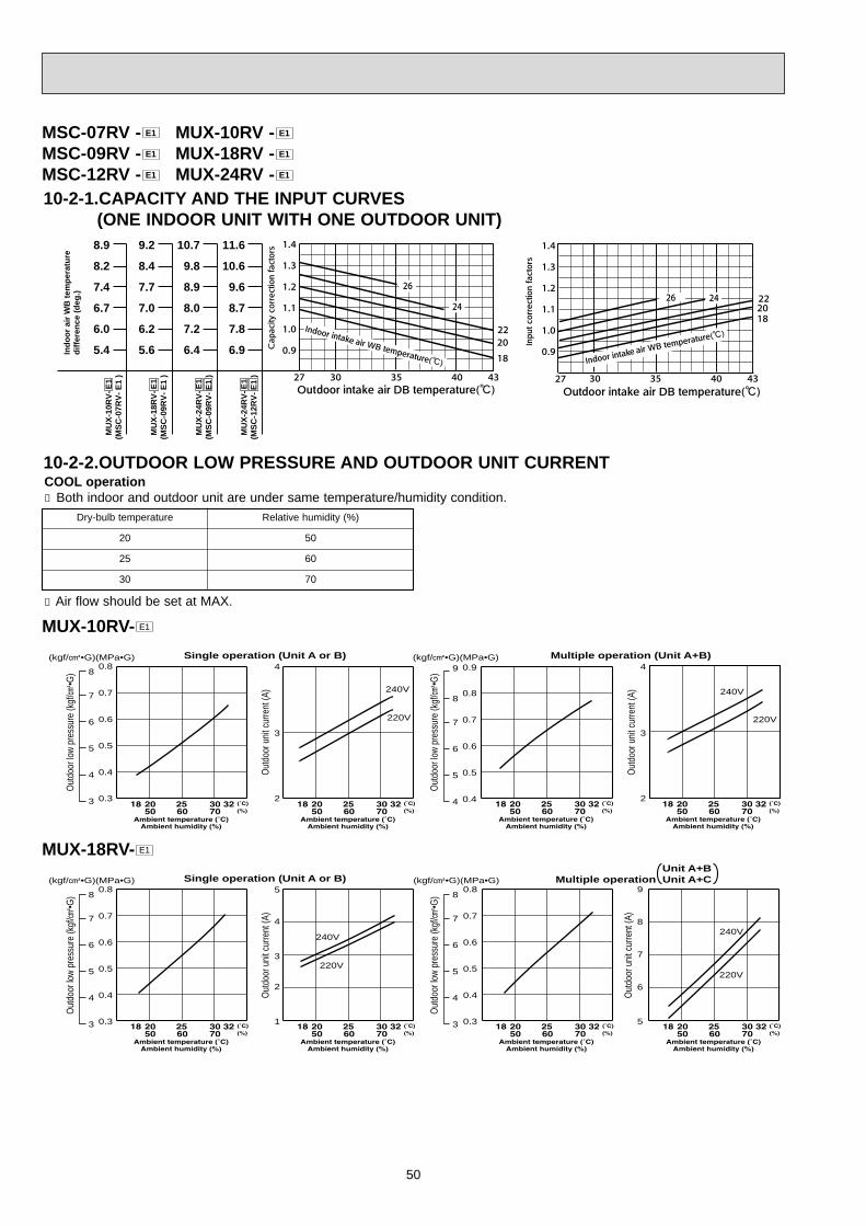
50
0.8
0.7
0.6
0.5
0.4
0.3
(kgf/F•G)(MPa•G)
Out
door
low
pres
sure
(kgf
/F•G
)
7
6
5
4
3
8
0.8
0.7
0.6
0.5
0.4
(kgf/F•G)(MPa•G)
Out
door
low
pres
sure
(kgf
/F•G
)
7
6
5
4
8
Out
door
uni
t cur
rent
(A)
Out
door
uni
t cur
rent
(A)
Single operation (Unit A or B) Multiple operation (Unit A+B)
0.8
0.7
0.6
0.5
0.4
0.3
(kgf/F•G)(MPa•G)
Out
door
low
pres
sure
(kgf
/F•G
)
7
6
5
4
3
80.8
0.7
0.6
0.5
0.4
0.3
(kgf/F•G)(MPa•G)
Out
door
low
pres
sure
(kgf
/F•G
)
7
6
5
4
3
8
Out
door
uni
t cur
rent
(A)
Out
door
uni
t cur
rent
(A)
Single operation (Unit A or B)Unit A+B
Multiple operation Unit A+C
4
3
2
4
3
2
5
4
2
3
1
8
9
7
6
5
240V
220V
9
240V
220V
240V
220V
240V
220V
0.9
70
Dry-bulb temperature Relative humidity (%)
50
60
20
25
30
10-2-2.OUTDOOR LOW PRESSURE AND OUTDOOR UNIT CURRENTCOOL operation① Both indoor and outdoor unit are under same temperature/humidity condition.
➁ Air flow should be set at MAX.
MUX-10RV- E1
MUX-18RV- E1
6.9
7.8
8.7
9.6
10.6
11.6M
UX
-24R
V-E
1(M
SC
-12R
V-
E1
)
6.4
7.2
8.0
8.9
9.8
10.7
MU
X-2
4RV
-E1
(MS
C-0
9RV
- E
1 )
5.6
6.2
7.0
7.7
8.4
9.2
5.4
6.0
6.7
7.4
8.2
8.9
MU
X-1
8RV
-E1
(MS
C-0
9RV
- E
1 )
MU
X-1
0RV
-E1
(MS
C-0
7RV
- E
1 )
Ind
oo
r ai
r W
B t
emp
erat
ure
dif
fere
nce
(d
eg.)
10-2-1.CAPACITY AND THE INPUT CURVES (ONE INDOOR UNIT WITH ONE OUTDOOR UNIT)
MSC-07RV -MSC-09RV -MSC-12RV - E1
E1
E1 MUX-10RV -MUX-18RV -MUX-24RV - E1
E1
E1

51
Out
door
uni
t cur
rent
(A)
Single operation (Unit A or B)
Multiple operation (Unit A+B)
Single operation (Unit C or D)
Multiple operation (Unit C+D)
Out
door
uni
t cur
rent
(A)
Out
door
uni
t cur
rent
(A)
Out
door
uni
t cur
rent
(A)
240V
220V
0.8
0.7
0.6
0.5
0.4
7
6
5
4
3
(kgf/F•G)(MPa•G)
Out
door
low
pres
sure
(kgf
/F•G
)
7
6
5
4
8
9
0.7
0.6
0.5
0.4
0.3
0.2
(kgf/F•G)(MPa•G)
Out
door
low
pres
sure
(kgf
/F•G
)
6
5
4
3
2
7 0.7
0.6
0.5
0.4
0.3
0.2
(kgf/F•G)(MPa•G)
Out
door
low
pres
sure
(kgf
/F•G
)
6
5
4
3
2
7
0.8
0.7
0.6
0.5
0.4
0.3
(kgf/F•G)(MPa•G)
Out
door
low
pres
sure
(kgf
/F•G
)
7
6
5
4
3
8
240V
220V
8
6
5
4
3
2
8
7
7
6
5
4
3
8
7
6
5
4
3
8
2 2
0.9
220V/240V
220V/240V
MUX-24RV- E1

52
10-3-1.Capacity and input correction by inverter output frequency (OUTDOOR UNIT:MXZ-18RV)NOTE 1 : Inverter output frequency : COOL 58Hz,HEAT 58HzNOTE 2 : The dotted line on graphs connects the frequency range in normal operation shown by the full line and the frequency
in test run shown by the point.1.07-class unit in single operation
1.5
1.0
0.5
30 40 50 60HzFrequency
<COOL>Capacity
1.5
1.0
0.5
30 40 50 60HzFrequency
<COOL>Total input
1.5
1.0
0.5
30 40 50 60 70HzFrequency
<HEAT>Capacity
1.5
1.0
0.5
Frequency
<HEAT>Total input
Frequency
<COOL>Capacity
1.5
1.0
0.5
30 40 50 60 70 80HzFrequency
<COOL>Capacity
Frequency
<COOL>Total input
Frequency
<HEAT>Capacity
Frequency
<HEAT>Total input
1.5
1.0
0.5
30 40 50 60 70 80HzFrequency
<COOL>Total input
1.5
1.0
0.5
30 40 50 60 70 80HzFrequency
<HEAT>Capacity
1.5
1.0
0.5
30 40 50 60 70 80HzFrequency
<HEAT>Total input
30 40 50 60 70Hz
1.5
1.0
0.5
30 40 50 60Hz
1.5
1.0
0.5
30 40 50 60Hz
1.5
1.0
0.5
30 40 50 60 70Hz
1.5
1.0
0.5
30 40 50 60 70Hz
2.09-class unit in single operation
3.12-class unit in single operation
MSC-07RV -MSC-09RV -MSC-12RV - E1
E1
E1 MXZ-18RV -MXZ-32RV - E1
E1

53
10-3-.2.Capacity and input correction by inverter output frequency
(OUTDOOR UNIT:MXZ-32RV)NOTE 1 : Inverter output frequency : COOL 58Hz,HEAT 40HzNOTE 2 : The dotted line on graphs connects the frequency range in normal operation shown by the full line and the frequency
in test run shown by the point.1.07-class unit in single operation
1.5
1.0
0.5
30 40 50 60HzFrequency
<COOL>Capacity
1.5
1.0
0.5
30 40 50 60HzFrequency
<COOL>Total input
1.5
1.0
0.5
30 40 50 60HzFrequency
<HEAT>Capacity
1.5
1.0
0.5
30 40 50 60HzFrequency
<HEAT>Total input
1.5
1.0
0.5
30 40 50 60HzFrequency
<COOL>Capacity
1.5
1.0
0.5
30 40 50 60 70 80HzFrequency
<COOL>Capacity
1.5
1.0
0.5
30 40 50 60HzFrequency
<COOL>Total input
1.5
1.0
0.5
30 40 50 60HzFrequency
<HEAT>Capacity
1.5
1.0
0.5
30 40 50 60HzFrequency
<HEAT>Total input
1.5
1.0
0.5
30 40 50 60 70 80HzFrequency
<COOL>Total input
1.5
1.0
0.5
30 40 50 60 70 80HzFrequency
<HEAT>Capacity
1.5
1.0
0.5
30 40 50 60 70 80HzFrequency
<HEAT>Total input
1.5
1.0
0.5
30 40 50 60 70 80HzFrequency
<COOL>Capacity
1.5
1.0
0.5
30 40 50 60 70 80HzFrequency
<COOL>Total input
1.5
1.0
0.5
30 40 50 60 70 80HzFrequency
<HEAT>Capacity
1.5
1.0
0.5
30 40 50 60 70 80HzFrequency
<HEAT>Total input
2.09-class unit in single operation
3.12-class unit in single operation
4.18-class unit in single operation

54
10-3-3.Outdoor low pressure and outdoor unit current 1.07-class unit in single operation(OUTDOOR UNIT : MXZ-18RV)
NOTE:The unit of pressure has been changed to MPa on the international system of units(SI unit system).The converted score against the traditional unit system can be gotten according to the formula below.
1(MPa • G) =10.2(kgf/ff • G)(1) COOL operation
1Both indoor and outdoor units are under the sametemperature/humidity condition.
Dry-bulb temperature(°C) Relative humidity(%)
20 50
25 60
30 70
<How to work fixed-frequency operation> 1.Set emergency switch to COOL or HEAT.The switch is locat-
ed on indoor unit.2.Press emergency run ON/OFF button.3.Compressor starts running at 58Hz (COOL / HEAT).4.Indoor fan runs at HI speed and continues for 30 minutes.5.To cancel this operation,press emergency run ON/OFF button
or any button on remote controller.
①
➁
Indoor Outdoor
Set air flow to Hi speed. Inverter output frequency is 58Hz.➂
(2) HEAT operation
DB(°C) 20.0
WB(°C) 14.5
DB(°C) 2 7 15 20.0
WB(°C) 1 6 12 14.5
0.6
0.5
0.4
0.3
0.218 20 25 30 32(oC) 50 60 70 (%) Ambient temperature(oC) / Ambient humidity(%)
Out
door
low
pre
ssur
e
8
7
6
5
4
318 20 25 30 32(oC) 50 60 70 (%) Ambient temperature(oC) / Ambient humidity(%)
58Hz 58Hz
0.6
0.5
0.4
0.3
0.22 5 10 15 20 Ambient temperature(oC)
2 5 10 15 20 Ambient temperature(oC)
10
9
8
7
6
Out
door
uni
t cur
rent
(A
)O
utdo
or u
nit c
urre
nt (
A)
58Hz
58Hz
(MPa•G)(kgf/F• G)
6
5
4
3
2
Out
door
low
pre
ssur
e
(MPa•G)(kgf/F• G)
6
5
4
3
2
220V
240V58Hz
220V
240V58Hz
2Air flow speed : HI3Inverter output frequency : 58Hz

55
2.09-class unit in single operation (OUTDOOR UNIT : MXZ-18RV)NOTE:The unit of pressure has been changed to MPa on the international system of units(SI unit system).
The converted score against the traditional unit system can be gotten according to the formula below.1(MPa • G) =10.2(kgf/ff • G)
(1) COOL operation
1Both indoor and outdoor units are under the same temperature/humidity condition.
Dry-bulb temperature(°C) Relative humidity(%)
20 50
25 60
30 70
<How to work fixed-frequency operation> 1.Set emergency switch to COOL or HEAT.The switch is locat-
ed on indoor unit.2.Press emergency run ON/OFF button.3.Compressor starts running at 58Hz (COOL / HEAT).4.Indoor fan runs at HI speed and continues for 30 minutes.5.To cancel this operation,press emergency run ON/OFF button
or any button on remote controller.2Air flow speed : HI3Inverter output frequency : 58Hz
①
➁
Indoor Outdoor
Set air flow to Hi speed. Inverter output frequency is 58Hz.➂
(2) HEAT operation
DB(°C) 20.0
WB(°C) 14.5
DB(°C) 2 7 15 20.0
WB(°C) 1 6 12 14.5
0.6
0.5
0.4
0.3
0.218 20 25 30 32(oC) 50 60 70 (%) Ambient temperature(oC) / Ambient humidity(%)
Out
door
low
pre
ssur
e
8
7
6
5
4
318 20 25 30 32(oC) 50 60 70 (%) Ambient temperature(oC) / Ambient humidity(%)
58Hz58Hz
0.6
0.5
0.4
0.3
0.22 5 10 15 20 Ambient temperature(oC)
2 5 10 15 20 Ambient temperature(oC)
10
9
8
7
6
Out
door
uni
t cur
rent
(A
)O
utdo
or u
nit c
urre
nt (
A)
58Hz
58Hz
(MPa•G)(kgf/F• G)
6
5
4
3
2
Out
door
low
pre
ssur
e
(MPa•G)(kgf/F• G)
6
5
4
3
2
220V
240V58Hz
220V
240V58Hz

56
3. 12-class unit in single operation (OUTDOOR UNIT : MXZ-18RV)NOTE:The unit of pressure has been changed to MPa on the international system of units(SI unit system).
The converted score against the traditional unit system can be gotten according to the formula below.1(MPa • G) =10.2(kgf/ff • G)
(1) COOL operation
1Both indoor and outdoor units are under the sametemperature/humidity condition.
Dry-bulb temperature(°C) Relative humidity(%)
20 50
25 60
30 70
<How to work fixed-frequency operation> 1.Set emergency switch to COOL or HEAT.The switch is locat-
ed on indoor unit.2.Press emergency run ON/OFF button.3.Compressor starts running at 58Hz (COOL/HEAT).4.Indoor fan runs at HI speed and continues for 30 minutes.5.To cancel this operation,press emergency run ON/OFF button
or any button on remote controller.2Air flow speed : HI3Inverter output frequency : 58Hz
①
➁
Indoor Outdoor
Set air flow to Hi speed. Inverter output frequency is 58Hz.➂
(2) HEAT operation
DB(°C) 20.0
WB(°C) 14.5
DB(°C) 2 7 15 20.0
WB(°C) 1 6 12 14.5
0.6
0.5
0.4
0.3
0.218 20 25 30 32(oC) 50 60 70 (%) Ambient temperature(oC) / Ambient humidity(%)
Out
door
low
pre
ssur
e
8
7
6
5
4
318 20 25 30 32(oC) 50 60 70 (%) Ambient temperature(oC) / Ambient humidity(%)
58Hz
0.6
0.5
0.4
0.3
0.22 5 10 15 20 Ambient temperature(oC)
2 5 10 15 20 Ambient temperature(oC)
10
9
8
7
6
Out
door
uni
t cur
rent
(A
)O
utdo
or u
nit c
urre
nt (
A)
58Hz
58Hz
(MPa•G)(kgf/F• G)
6
5
4
3
2
Out
door
low
pre
ssur
e
(MPa•G)(kgf/F• G)
6
5
4
3
2
240V58Hz
220V
240V58Hz

57
10-3-4.Outdoor low pressure and outdoor unit current 1. 07-class unit in single operation (OUTDOOR UNIT : MXZ-32RV)
NOTO:The unit of pressure has been changed to MPa on the international system of units(SI unit system).The converted score against the traditional unit system can be gotten according to the formula below.
1(MPa • G) =10.2(kgf/ff • G)(1) COOL operation
1Both indoor and outdoor units are under the sametemperature/humidity condition.
Dry-bulb temperature(°C) Relative humidity(%)
20 50
25 60
30 70
<How to work fixed-frequency operation> 1.Set emergency switch to COOL or HEAT.The switch is locat-
ed on indoor unit.2.Press emergency run ON/OFF button.3.Compressor starts running at 58Hz (COOL) or 40Hz (HEAT).4.Indoor fan runs at HI speed and continues for 30 minutes.5.To cancel this operation,press emergency run ON/OFF button
or any button on remote controller.
①
➁
Indoor Outdoor
Set air flow to Hi speed. Inverter output frequency is 40Hz.➂
(2) HEAT operation
DB(°C) 20.0
WB(°C) 14.5
DB(°C) 2 7 15 20.0
WB(°C) 1 6 12 14.5
0.6
0.5
0.4
0.3
0.218 20 25 30 32(oC) 50 60 70 (%) Ambient temperature(oC) / Ambient humidity(%)
Out
door
low
pre
ssur
e
11
10
9
8
7
618 20 25 30 32(oC) 50 60 70 (%) Ambient temperature(oC) / Ambient humidity(%)
58Hz58Hz
2 5 10 15 20 Ambient temperature(oC)
10
9
8
7
6
Out
door
uni
t cur
rent
(A
)O
utdo
or u
nit c
urre
nt (
A)
40Hz
(MPa•G)(kgf/F• G)
6
5
4
3
2
2Air flow speed : HI3Inverter output frequency : 58Hz

58
2. 09-class unit in single operation (OUTDOOR UNIT : MXZ-32RV)NOTO:The unit of pressure has been changed to MPa on the international system of units(SI unit system).
The converted score against the traditional unit system can be gotten according to the formula below.1(MPa • G) =10.2(kgf/ff • G)
(1) COOL operation
1Both indoor and outdoor units are under the same temperature/humidity condition.
Dry-bulb temperature(°C) Relative humidity(%)
20 50
25 60
30 70
<How to work fixed-frequency operation> 1.Set emergency switch to COOL or HEAT.The switch is locat-
ed on indoor unit.2.Press emergency run ON/OFF button.3.Compressor starts running at 58Hz (COOL) or 40Hz (HEAT).4.Indoor fan runs at HI speed and continues for 30 minutes.5.To cancel this operation,press emergency run ON/OFF button
or any button on remote controller.2Air flow speed : HI3Inverter output frequency : 58Hz
①
➁
Indoor Outdoor
Set air flow to Hi speed. Inverter output frequency is 40Hz.➂
(2) HEAT operation
DB(°C) 20.0
WB(°C) 14.5
DB(°C) 2 7 15 20.0
WB(°C) 1 6 12 14.5
7
6
5
4
3 18 20 25 30 32(oC) 50 60 70 (%) Ambient temperature(oC) / Ambient humidity(%)
11
10
9
8
7
618 20 25 30 32(oC) 50 60 70 (%) Ambient temperature(oC) / Ambient humidity(%)
58Hz 58Hz
2 5 10 15 20 Ambient temperature(oC)
9
8
7
6
5
Out
door
uni
t cur
rent
(A
)O
utdo
or u
nit c
urre
nt (
A)
40Hz
0.7
0.6
0.5
0.4
0.3
Out
door
low
pre
ssur
e
(MPa•G)(kgf/F• G)

59
3. 12(13)-class unit in single operation (OUTDOOR UNIT : MXZ-32RV)NOTO:The unit of pressure has been changed to MPa on the international system of units(SI unit system).
The converted score against the traditional unit system can be gotten according to the formula below.1(MPa • G) =10.2(kgf/ff • G)
(1) COOL operation
1Both indoor and outdoor units are under the sametemperature/humidity condition.
Dry-bulb temperature(°C) Relative humidity(%)
20 50
25 60
30 70
<How to work fixed-frequency operation> 1.Set emergency switch to COOL or HEAT.The switch is locat-
ed on indoor unit.2.Press emergency run ON/OFF button.3.Compressor starts running at 58Hz (COOL) or 40Hz (HEAT).4.Indoor fan runs at HI speed and continues for 30 minutes.5.To cancel this operation,press emergency run ON/OFF button
or any button on remote controller.2Air flow speed : HI3Inverter output frequency : 58Hz
①
➁
Indoor Outdoor
Set air flow to Hi speed. Inverter output frequency is 40Hz.➂
(2) HEAT operation
DB(°C) 20.0
WB(°C) 14.5
DB(°C) 2 7 15 20.0
WB(°C) 1 6 12 14.5
0.8
0.7
0.6
0.5
0.4
0.3 18 20 25 30 32(oC) 50 60 70 (%) Ambient temperature(oC) / Ambient humidily(%)
11
10
9
8
7
618 20 25 30 32(oC) 50 60 70 (%) Ambient temperature(oC) / Ambient humidily(%)
58Hz58Hz
2 5 10 15 20 Ambient temperature(oC)
9
8
7
6
5
Out
door
uni
t cur
rent
(A
)O
utdo
or u
nit c
urre
nt (
A)
40Hz
Out
door
low
pre
ssur
e
(MPa•G)(kgf/F• G)
8
7
6
5
4
3

60
4. 18-class unit in single operationNOTO:The unit of pressure has been changed to MPa on the international system of units(SI unit system).
The converted score against the traditional unit system can be gotten according to the formula below.1(MPa • G) =10.2(kgf/ff • G)
(1) COOL operation
①
➁
Both indoor and outdoor units are under the sametemperature/humidity condition.
Dry-bulb temperature(°C) Relative humidity(%)
20 50
25 60
30 70
<How to work fixed-frequency operation> 1.Set emergency switch to COOL or HEAT.The switch is locat-
ed on indoor unit.2.Press emergency run ON/OFF button.3.Compressor starts running at 58Hz (COOL) or 40Hz (HEAT).4.Indoor fan runs at HI speed.5.To cancel this operation,press emergency run ON/OFF button
or any button on remote controller.Air flow speed : HIInverter output frequency : 58Hz➂
①
➁
Indoor Outdoor
Set air flow to Hi speed. Inverter output frequency is 58Hz.➂
(2) HEAT operation
DB(°C) 20.0
WB(°C) 14.5
DB(°C) 2 7 15 20.0
WB(°C) 1 6 12 14.5
0.8
0.7
0.6
0.5
0.4
0.3 18 20 25 30 32(oC) 50 60 70 (%) Ambient temperature(oC) / Ambient humidily(%)
11
10
9
8
7
618 20 25 30 32(oC) 50 60 70 (%) Ambient temperature(oC) / Ambient humidily(%)
58Hz58Hz
2 5 10 15 20 Ambient temperature(oC)
9
8
7
6
5
Out
door
uni
t cur
rent
(A
)O
utdo
or u
nit c
urre
nt (
A)
40Hz
Out
door
low
pre
ssur
e
(MPa•G)(kgf/F• G)
8
7
6
5
4
3

61
MSC-07RV - : MU-07RV - E1E1
PERFORMANCE DATACOOL operation (220V)
OUTDOOR DB(;)INDOOR INDOOR 21 25 27 30DB(;) WB(;) Q SHC SHF INPUT Q SHC SHF INPUT Q SHC SHF INPUT Q SHC SHF INPUT
21 18 2.59 1.45 0.56 544 2.48 1.39 0.56 571 2.38 1.33 0.56 598 2.29 1.28 0.56 62621 20 2.70 1.19 0.44 571 2.59 1.14 0.44 605 2.51 1.10 0.44 619 2.42 1.06 0.44 64622 18 2.59 1.55 0.60 544 2.48 1.49 0.60 571 2.38 1.43 0.60 598 2.29 1.37 0.60 62622 20 2.70 1.29 0.48 571 2.59 1.24 0.48 605 2.51 1.20 0.48 619 2.42 1.16 0.48 64622 22 2.81 1.01 0.36 592 2.71 0.97 0.36 629 2.64 0.95 0.36 646 2.53 0.91 0.36 67323 18 2.59 1.65 0.64 544 2.48 1.58 0.64 571 2.38 1.52 0.64 598 2.29 1.46 0.64 62623 20 2.70 1.40 0.52 571 2.59 1.34 0.52 605 2.51 1.30 0.52 619 2.42 1.26 0.52 64623 22 2.81 1.12 0.40 592 2.71 1.08 0.40 629 2.64 1.06 0.40 646 2.53 1.01 0.40 67324 18 2.59 1.76 0.68 544 2.48 1.68 0.68 571 2.38 1.62 0.68 598 2.29 1.56 0.68 62624 20 2.70 1.51 0.56 571 2.59 1.45 0.56 605 2.51 1.40 0.56 619 2.42 1.36 0.56 64624 22 2.81 1.23 0.44 592 2.71 1.19 0.44 629 2.64 1.16 0.44 646 2.53 1.11 0.44 67324 24 2.95 0.94 0.32 619 2.84 0.91 0.32 653 2.77 0.89 0.32 673 2.68 0.86 0.32 70725 20 2.70 1.62 0.60 571 2.59 1.55 0.60 605 2.51 1.50 0.60 619 2.42 1.45 0.60 64625 22 2.81 1.35 0.48 592 2.71 1.30 0.48 629 2.64 1.27 0.48 646 2.53 1.21 0.48 67325 24 2.95 1.06 0.36 619 2.84 1.02 0.36 653 2.77 1.00 0.36 673 2.68 0.97 0.36 70726 18 2.59 1.96 0.76 544 2.48 1.88 0.76 571 2.38 1.81 0.76 598 2.29 1.74 0.76 62626 20 2.70 1.72 0.64 571 2.59 1.65 0.64 605 2.51 1.61 0.64 619 2.42 1.55 0.64 64626 22 2.81 1.46 0.52 592 2.71 1.41 0.52 629 2.64 1.37 0.52 646 2.53 1.32 0.52 67326 24 2.95 1.18 0.40 619 2.84 1.14 0.40 653 2.77 1.11 0.40 673 2.68 1.07 0.40 70726 26 3.04 0.85 0.28 653 2.95 0.83 0.28 687 2.90 0.81 0.28 707 2.82 0.79 0.28 72827 18 2.59 2.07 0.80 544 2.48 1.98 0.80 571 2.38 1.90 0.80 598 2.29 1.83 0.80 62627 20 2.70 1.83 0.68 571 2.59 1.76 0.68 605 2.51 1.71 0.68 619 2.42 1.65 0.68 64627 22 2.81 1.57 0.56 592 2.71 1.52 0.56 629 2.64 1.48 0.56 646 2.53 1.42 0.56 67327 24 2.95 1.30 0.44 619 2.84 1.25 0.44 653 2.77 1.22 0.44 673 2.68 1.18 0.44 70727 26 3.04 0.97 0.32 653 2.95 0.94 0.32 687 2.90 0.93 0.32 707 2.82 0.90 0.32 72828 18 2.59 2.17 0.84 544 2.48 2.08 0.84 571 2.38 2.00 0.84 598 2.29 1.92 0.84 62628 20 2.70 1.94 0.72 571 2.59 1.86 0.72 605 2.51 1.81 0.72 619 2.42 1.74 0.72 64628 22 2.81 1.68 0.60 592 2.71 1.62 0.60 629 2.64 1.58 0.60 646 2.53 1.52 0.60 67328 24 2.95 1.42 0.48 619 2.84 1.36 0.48 653 2.77 1.33 0.48 673 2.68 1.29 0.48 70728 26 3.04 1.09 0.36 653 2.95 1.06 0.36 687 2.90 1.05 0.36 707 2.82 1.01 0.36 72829 18 2.59 2.27 0.88 544 2.48 2.18 0.88 571 2.38 2.09 0.88 598 2.29 2.01 0.88 62629 20 2.70 2.05 0.76 571 2.59 1.96 0.76 605 2.51 1.91 0.76 619 2.42 1.84 0.76 64629 22 2.81 1.80 0.64 592 2.71 1.73 0.64 629 2.64 1.69 0.64 646 2.53 1.62 0.64 67329 24 2.95 1.53 0.52 619 2.84 1.48 0.52 653 2.77 1.44 0.52 673 2.68 1.40 0.52 70729 26 3.04 1.21 0.40 653 2.95 1.18 0.40 687 2.90 1.16 0.40 707 2.82 1.13 0.40 72830 18 2.59 2.38 0.92 544 2.48 2.28 0.92 571 2.38 2.19 0.92 598 2.29 2.10 0.92 62630 20 2.70 2.16 0.80 571 2.59 2.07 0.80 605 2.51 2.01 0.80 619 2.42 1.94 0.80 64630 22 2.81 1.91 0.68 592 2.71 1.84 0.68 629 2.64 1.80 0.68 646 2.53 1.72 0.68 67330 24 2.95 1.65 0.56 619 2.84 1.59 0.56 653 2.77 1.55 0.56 673 2.68 1.50 0.56 70730 26 3.04 1.34 0.44 653 2.95 1.30 0.44 687 2.90 1.28 0.44 707 2.82 1.24 0.44 72831 18 2.59 2.48 0.96 544 2.48 2.38 0.96 571 2.38 2.28 0.96 598 2.29 2.20 0.96 62631 20 2.70 2.26 0.84 571 2.59 2.17 0.84 605 2.51 2.11 0.84 619 2.42 2.03 0.84 64631 22 2.81 2.02 0.72 592 2.71 1.95 0.72 629 2.64 1.90 0.72 646 2.53 1.82 0.72 67331 24 2.95 1.77 0.60 619 2.84 1.70 0.60 653 2.77 1.66 0.60 673 2.68 1.61 0.60 70731 26 3.04 1.46 0.48 653 2.95 1.42 0.48 687 2.90 1.39 0.48 707 2.82 1.35 0.48 72832 18 2.59 2.59 1.00 544 2.48 2.48 1.00 571 2.38 2.38 1.00 598 2.29 2.29 1.00 62632 20 2.70 2.37 0.88 571 2.59 2.27 0.88 605 2.51 2.21 0.88 619 2.42 2.13 0.88 64632 22 2.81 2.13 0.76 592 2.71 2.06 0.76 629 2.64 2.01 0.76 646 2.53 1.92 0.76 67332 24 2.95 1.89 0.64 619 2.84 1.82 0.64 653 2.77 1.77 0.64 673 2.68 1.72 0.64 70732 26 3.04 1.58 0.52 653 2.95 1.53 0.52 687 2.90 1.51 0.52 707 2.82 1.46 0.52 728
CAPACITY : 2.2 kW INPUT : 680 W SHF : 0.74
NOTE Q :Total capacity (kW) SHF :Sensible heat factorSHC :Sensible heat capacity (kW) INPUT :Total power input (W)

62
MSC-07RV - : MU-07RV - E1E1
PERFORMANCE DATACOOL operation (220V)
OUTDOOR DB(;)INDOOR INDOOR 35 40 43DB(;) WB(;) Q SHC SHF INPUT Q SHC SHF INPUT
21 18 2.16 1.21 0.56 666 1.98 1.11 0.56 70721 20 2.27 1.00 0.44 694 2.11 0.93 0.44 72822 18 2.16 1.29 0.60 666 1.98 1.19 0.60 70722 20 2.27 1.09 0.48 694 2.11 1.01 0.48 72822 22 2.40 0.86 0.36 721 2.24 0.81 0.36 76223 18 2.16 1.38 0.64 666 1.98 1.27 0.64 70723 20 2.27 1.18 0.52 694 2.11 1.10 0.52 72823 22 2.40 0.96 0.40 721 2.24 0.90 0.40 76224 18 2.16 1.47 0.68 666 1.98 1.35 0.68 70724 20 2.27 1.27 0.56 694 2.11 1.18 0.56 72824 22 2.40 1.06 0.44 721 2.24 0.99 0.44 76224 24 2.53 0.81 0.32 748 2.38 0.76 0.32 78225 20 2.27 1.36 0.60 694 2.11 1.27 0.60 72825 22 2.40 1.15 0.48 721 2.24 1.08 0.48 76225 24 2.53 0.91 0.36 748 2.38 0.86 0.36 78226 18 2.16 1.64 0.76 666 1.98 1.50 0.76 70726 20 2.27 1.45 0.64 694 2.11 1.35 0.64 72826 22 2.40 1.25 0.52 721 2.24 1.17 0.52 76226 24 2.53 1.01 0.40 748 2.38 0.95 0.40 78226 26 2.66 0.75 0.28 775 2.51 0.70 0.28 80927 18 2.16 1.72 0.80 666 1.98 1.58 0.80 70727 20 2.27 1.54 0.68 694 2.11 1.44 0.68 72827 22 2.40 1.34 0.56 721 2.24 1.26 0.56 76227 24 2.53 1.11 0.44 748 2.38 1.05 0.44 78227 26 2.66 0.85 0.32 775 2.51 0.80 0.32 80928 18 2.16 1.81 0.84 666 1.98 1.66 0.84 70728 20 2.27 1.63 0.72 694 2.11 1.52 0.72 72828 22 2.40 1.44 0.60 721 2.24 1.35 0.60 76228 24 2.53 1.21 0.48 748 2.38 1.14 0.48 78228 26 2.66 0.96 0.36 775 2.51 0.90 0.36 80929 18 2.16 1.90 0.88 666 1.98 1.74 0.88 70729 20 2.27 1.72 0.76 694 2.11 1.61 0.76 72829 22 2.40 1.53 0.64 721 2.24 1.44 0.64 76229 24 2.53 1.32 0.52 748 2.38 1.24 0.52 78229 26 2.66 1.06 0.40 775 2.51 1.00 0.40 80930 18 2.16 1.98 0.92 666 1.98 1.82 0.92 70730 20 2.27 1.81 0.80 694 2.11 1.69 0.80 72830 22 2.40 1.63 0.68 721 2.24 1.53 0.68 76230 24 2.53 1.42 0.56 748 2.38 1.33 0.56 78230 26 2.66 1.17 0.44 775 2.51 1.10 0.44 80931 18 2.16 2.07 0.96 666 1.98 1.90 0.96 70731 20 2.27 1.90 0.84 694 2.11 1.77 0.84 72831 22 2.40 1.73 0.72 721 2.24 1.62 0.72 76231 24 2.53 1.52 0.60 748 2.38 1.43 0.60 78231 26 2.66 1.28 0.48 775 2.51 1.20 0.48 80932 18 2.16 2.16 1.00 666 1.98 1.98 1.00 70732 20 2.27 1.99 0.88 694 2.11 1.86 0.88 72832 22 2.40 1.82 0.76 721 2.24 1.71 0.76 76232 24 2.53 1.62 0.64 748 2.38 1.52 0.64 78232 26 2.66 1.38 0.52 775 2.51 1.30 0.52 809
CAPACITY : 2.2 kW INPUT : 680 W SHF : 0.74
Q SHC SHF INPUT1.90 1.07 0.56 7212.04 0.90 0.44 7481.90 1.14 0.60 7212.04 0.98 0.48 7482.17 0.78 0.36 7751.90 1.22 0.64 7212.04 1.06 0.52 7482.17 0.87 0.40 7751.90 1.29 0.68 7212.04 1.14 0.56 7482.17 0.95 0.44 7752.31 0.74 0.32 7992.04 1.22 0.60 7482.17 1.04 0.48 7752.31 0.83 0.36 7991.90 1.45 0.76 7212.04 1.30 0.64 7482.17 1.13 0.52 7752.31 0.92 0.40 7992.43 0.68 0.28 8261.90 1.52 0.80 7212.04 1.38 0.68 7482.17 1.21 0.56 7752.31 1.02 0.44 7992.43 0.78 0.32 8261.90 1.60 0.84 7212.04 1.47 0.72 7482.17 1.30 0.60 7752.31 1.11 0.48 7992.43 0.88 0.36 8261.90 1.67 0.88 7212.04 1.55 0.76 7482.17 1.39 0.64 7752.31 1.20 0.52 7992.43 0.97 0.40 8261.90 1.75 0.92 7212.04 1.63 0.80 7482.17 1.47 0.68 7752.31 1.29 0.56 7992.43 1.07 0.44 8261.90 1.83 0.96 7212.04 1.71 0.84 7482.17 1.56 0.72 7752.31 1.39 0.60 7992.43 1.17 0.48 8261.90 1.90 1.00 7212.04 1.79 0.88 7482.17 1.65 0.76 7752.31 1.48 0.64 7992.43 1.26 0.52 826
NOTE Q :Total capacity (kW) SHF :Sensible heat factorSHC :Sensible heat capacity (kW) INPUT :Total power input (W)

63
MSC-07RV - : MU-07RV - E1E1
PERFORMANCE DATACOOL operation (240V)
OUTDOOR DB(;)INDOOR INDOOR 21 25 27 30DB(;) WB(;) Q SHC SHF INPUT Q SHC SHF INPUT Q SHC SHF INPUT Q SHC SHF INPUT
21 18 2.59 1.45 0.56 568 2.48 1.39 0.56 596 2.38 1.33 0.56 625 2.29 1.28 0.56 65321 20 2.70 1.19 0.44 596 2.59 1.14 0.44 632 2.51 1.10 0.44 646 2.42 1.06 0.44 67522 18 2.59 1.55 0.60 568 2.48 1.49 0.60 596 2.38 1.43 0.60 625 2.29 1.37 0.60 65322 20 2.70 1.29 0.48 596 2.59 1.24 0.48 632 2.51 1.20 0.48 646 2.42 1.16 0.48 67522 22 2.81 1.01 0.36 618 2.71 0.97 0.36 657 2.64 0.95 0.36 675 2.53 0.91 0.36 70323 18 2.59 1.65 0.64 568 2.48 1.58 0.64 596 2.38 1.52 0.64 625 2.29 1.46 0.64 65323 20 2.70 1.40 0.52 596 2.59 1.34 0.52 632 2.51 1.30 0.52 646 2.42 1.26 0.52 67523 22 2.81 1.12 0.40 618 2.71 1.08 0.40 657 2.64 1.06 0.40 675 2.53 1.01 0.40 70324 18 2.59 1.76 0.68 568 2.48 1.68 0.68 596 2.38 1.62 0.68 625 2.29 1.56 0.68 65324 20 2.70 1.51 0.56 596 2.59 1.45 0.56 632 2.51 1.40 0.56 646 2.42 1.36 0.56 67524 22 2.81 1.23 0.44 618 2.71 1.19 0.44 657 2.64 1.16 0.44 675 2.53 1.11 0.44 70324 24 2.95 0.94 0.32 646 2.84 0.91 0.32 682 2.77 0.89 0.32 703 2.68 0.86 0.32 73825 20 2.70 1.62 0.60 596 2.59 1.55 0.60 632 2.51 1.50 0.60 646 2.42 1.45 0.60 67525 22 2.81 1.35 0.48 618 2.71 1.30 0.48 657 2.64 1.27 0.48 675 2.53 1.21 0.48 70325 24 2.95 1.06 0.36 646 2.84 1.02 0.36 682 2.77 1.00 0.36 703 2.68 0.97 0.36 73826 18 2.59 1.96 0.76 568 2.48 1.88 0.76 596 2.38 1.81 0.76 625 2.29 1.74 0.76 65326 20 2.70 1.72 0.64 596 2.59 1.65 0.64 632 2.51 1.61 0.64 646 2.42 1.55 0.64 67526 22 2.81 1.46 0.52 618 2.71 1.41 0.52 657 2.64 1.37 0.52 675 2.53 1.32 0.52 70326 24 2.95 1.18 0.40 646 2.84 1.14 0.40 682 2.77 1.11 0.40 703 2.68 1.07 0.40 73826 26 3.04 0.85 0.28 682 2.95 0.83 0.28 717 2.90 0.81 0.28 738 2.82 0.79 0.28 76027 18 2.59 2.07 0.80 568 2.48 1.98 0.80 596 2.38 1.90 0.80 625 2.29 1.83 0.80 65327 20 2.70 1.83 0.68 596 2.59 1.76 0.68 632 2.51 1.71 0.68 646 2.42 1.65 0.68 67527 22 2.81 1.57 0.56 618 2.71 1.52 0.56 657 2.64 1.48 0.56 675 2.53 1.42 0.56 70327 24 2.95 1.30 0.44 646 2.84 1.25 0.44 682 2.77 1.22 0.44 703 2.68 1.18 0.44 73827 26 3.04 0.97 0.32 682 2.95 0.94 0.32 717 2.90 0.93 0.32 738 2.82 0.90 0.32 76028 18 2.59 2.17 0.84 568 2.48 2.08 0.84 596 2.38 2.00 0.84 625 2.29 1.92 0.84 65328 20 2.70 1.94 0.72 596 2.59 1.86 0.72 632 2.51 1.81 0.72 646 2.42 1.74 0.72 67528 22 2.81 1.68 0.60 618 2.71 1.62 0.60 657 2.64 1.58 0.60 675 2.53 1.52 0.60 70328 24 2.95 1.42 0.48 646 2.84 1.36 0.48 682 2.77 1.33 0.48 703 2.68 1.29 0.48 73828 26 3.04 1.09 0.36 682 2.95 1.06 0.36 717 2.90 1.05 0.36 738 2.82 1.01 0.36 76029 18 2.59 2.27 0.88 568 2.48 2.18 0.88 596 2.38 2.09 0.88 625 2.29 2.01 0.88 65329 20 2.70 2.05 0.76 596 2.59 1.96 0.76 632 2.51 1.91 0.76 646 2.42 1.84 0.76 67529 22 2.81 1.80 0.64 618 2.71 1.73 0.64 657 2.64 1.69 0.64 675 2.53 1.62 0.64 70329 24 2.95 1.53 0.52 646 2.84 1.48 0.52 682 2.77 1.44 0.52 703 2.68 1.40 0.52 73829 26 3.04 1.21 0.40 682 2.95 1.18 0.40 717 2.90 1.16 0.40 738 2.82 1.13 0.40 76030 18 2.59 2.38 0.92 568 2.48 2.28 0.92 596 2.38 2.19 0.92 625 2.29 2.10 0.92 65330 20 2.70 2.16 0.80 596 2.59 2.07 0.80 632 2.51 2.01 0.80 646 2.42 1.94 0.80 67530 22 2.81 1.91 0.68 618 2.71 1.84 0.68 657 2.64 1.80 0.68 675 2.53 1.72 0.68 70330 24 2.95 1.65 0.56 646 2.84 1.59 0.56 682 2.77 1.55 0.56 703 2.68 1.50 0.56 73830 26 3.04 1.34 0.44 682 2.95 1.30 0.44 717 2.90 1.28 0.44 738 2.82 1.24 0.44 76031 18 2.59 2.48 0.96 568 2.48 2.38 0.96 596 2.38 2.28 0.96 625 2.29 2.20 0.96 65331 20 2.70 2.26 0.84 596 2.59 2.17 0.84 632 2.51 2.11 0.84 646 2.42 2.03 0.84 67531 22 2.81 2.02 0.72 618 2.71 1.95 0.72 657 2.64 1.90 0.72 675 2.53 1.82 0.72 70331 24 2.95 1.77 0.60 646 2.84 1.70 0.60 682 2.77 1.66 0.60 703 2.68 1.61 0.60 73831 26 3.04 1.46 0.48 682 2.95 1.42 0.48 717 2.90 1.39 0.48 738 2.82 1.35 0.48 76032 18 2.59 2.59 1.00 568 2.48 2.48 1.00 596 2.38 2.38 1.00 625 2.29 2.29 1.00 65332 20 2.70 2.37 0.88 596 2.59 2.27 0.88 632 2.51 2.21 0.88 646 2.42 2.13 0.88 67532 22 2.81 2.13 0.76 618 2.71 2.06 0.76 657 2.64 2.01 0.76 675 2.53 1.92 0.76 70332 24 2.95 1.89 0.64 646 2.84 1.82 0.64 682 2.77 1.77 0.64 703 2.68 1.72 0.64 73832 26 3.04 1.58 0.52 682 2.95 1.53 0.52 717 2.90 1.51 0.52 738 2.82 1.46 0.52 760
CAPACITY : 2.2 kW INPUT : 710 W SHF : 0.74
NOTE Q :Total capacity (kW) SHF :Sensible heat factorSHC :Sensible heat capacity (kW) INPUT :Total power input (W)

64
MSC-07RV - : MU-07RV - E1E1
PERFORMANCE DATACOOL operation (240V)
OUTDOOR DB(;)INDOOR INDOOR 35 40 43DB(;) WB(;) Q SHC SHF INPUT Q SHC SHF INPUT
21 18 2.16 1.21 0.56 696 1.98 1.11 0.56 73821 20 2.27 1.00 0.44 724 2.11 0.93 0.44 76022 18 2.16 1.29 0.60 696 1.98 1.19 0.60 73822 20 2.27 1.09 0.48 724 2.11 1.01 0.48 76022 22 2.40 0.86 0.36 753 2.24 0.81 0.36 79523 18 2.16 1.38 0.64 696 1.98 1.27 0.64 73823 20 2.27 1.18 0.52 724 2.11 1.10 0.52 76023 22 2.40 0.96 0.40 753 2.24 0.90 0.40 79524 18 2.16 1.47 0.68 696 1.98 1.35 0.68 73824 20 2.27 1.27 0.56 724 2.11 1.18 0.56 76024 22 2.40 1.06 0.44 753 2.24 0.99 0.44 79524 24 2.53 0.81 0.32 781 2.38 0.76 0.32 81725 20 2.27 1.36 0.60 724 2.11 1.27 0.60 76025 22 2.40 1.15 0.48 753 2.24 1.08 0.48 79525 24 2.53 0.91 0.36 781 2.38 0.86 0.36 81726 18 2.16 1.64 0.76 696 1.98 1.50 0.76 73826 20 2.27 1.45 0.64 724 2.11 1.35 0.64 76026 22 2.40 1.25 0.52 753 2.24 1.17 0.52 79526 24 2.53 1.01 0.40 781 2.38 0.95 0.40 81726 26 2.66 0.75 0.28 809 2.51 0.70 0.28 84527 18 2.16 1.72 0.80 696 1.98 1.58 0.80 73827 20 2.27 1.54 0.68 724 2.11 1.44 0.68 76027 22 2.40 1.34 0.56 753 2.24 1.26 0.56 79527 24 2.53 1.11 0.44 781 2.38 1.05 0.44 81727 26 2.66 0.85 0.32 809 2.51 0.80 0.32 84528 18 2.16 1.81 0.84 696 1.98 1.66 0.84 73828 20 2.27 1.63 0.72 724 2.11 1.52 0.72 76028 22 2.40 1.44 0.60 753 2.24 1.35 0.60 79528 24 2.53 1.21 0.48 781 2.38 1.14 0.48 81728 26 2.66 0.96 0.36 809 2.51 0.90 0.36 84529 18 2.16 1.90 0.88 696 1.98 1.74 0.88 73829 20 2.27 1.72 0.76 724 2.11 1.61 0.76 76029 22 2.40 1.53 0.64 753 2.24 1.44 0.64 79529 24 2.53 1.32 0.52 781 2.38 1.24 0.52 81729 26 2.66 1.06 0.40 809 2.51 1.00 0.40 84530 18 2.16 1.98 0.92 696 1.98 1.82 0.92 73830 20 2.27 1.81 0.80 724 2.11 1.69 0.80 76030 22 2.40 1.63 0.68 753 2.24 1.53 0.68 79530 24 2.53 1.42 0.56 781 2.38 1.33 0.56 81730 26 2.66 1.17 0.44 809 2.51 1.10 0.44 84531 18 2.16 2.07 0.96 696 1.98 1.90 0.96 73831 20 2.27 1.90 0.84 724 2.11 1.77 0.84 76031 22 2.40 1.73 0.72 753 2.24 1.62 0.72 79531 24 2.53 1.52 0.60 781 2.38 1.43 0.60 81731 26 2.66 1.28 0.48 809 2.51 1.20 0.48 84532 18 2.16 2.16 1.00 696 1.98 1.98 1.00 73832 20 2.27 1.99 0.88 724 2.11 1.86 0.88 76032 22 2.40 1.82 0.76 753 2.24 1.71 0.76 79532 24 2.53 1.62 0.64 781 2.38 1.52 0.64 81732 26 2.66 1.38 0.52 809 2.51 1.30 0.52 845
CAPACITY : 2.2 kW INPUT : 710 W SHF : 0.74
Q SHC SHF INPUT1.90 1.07 0.56 7532.04 0.90 0.44 7811.90 1.14 0.60 7532.04 0.98 0.48 7812.17 0.78 0.36 8091.90 1.22 0.64 7532.04 1.06 0.52 7812.17 0.87 0.40 8091.90 1.29 0.68 7532.04 1.14 0.56 7812.17 0.95 0.44 8092.31 0.74 0.32 8342.04 1.22 0.60 7812.17 1.04 0.48 8092.31 0.83 0.36 8341.90 1.45 0.76 7532.04 1.30 0.64 7812.17 1.13 0.52 8092.31 0.92 0.40 8342.43 0.68 0.28 8631.90 1.52 0.80 7532.04 1.38 0.68 7812.17 1.21 0.56 8092.31 1.02 0.44 8342.43 0.78 0.32 8631.90 1.60 0.84 7532.04 1.47 0.72 7812.17 1.30 0.60 8092.31 1.11 0.48 8342.43 0.88 0.36 8631.90 1.67 0.88 7532.04 1.55 0.76 7812.17 1.39 0.64 8092.31 1.20 0.52 8342.43 0.97 0.40 8631.90 1.75 0.92 7532.04 1.63 0.80 7812.17 1.47 0.68 8092.31 1.29 0.56 8342.43 1.07 0.44 8631.90 1.83 0.96 7532.04 1.71 0.84 7812.17 1.56 0.72 8092.31 1.39 0.60 8342.43 1.17 0.48 8631.90 1.90 1.00 7532.04 1.79 0.88 7812.17 1.65 0.76 8092.31 1.48 0.64 8342.43 1.26 0.52 863
NOTE Q :Total capacity (kW) SHF :Sensible heat factorSHC :Sensible heat capacity (kW) INPUT :Total power input (W)

65
MSC-09RV - : MU-09RV - E1E1
PERFORMANCE DATACOOL operation (220V)
OUTDOOR DB(;)INDOOR INDOOR 21 25 27 30DB(;) WB(;) Q SHC SHF INPUT Q SHC SHF INPUT Q SHC SHF INPUT Q SHC SHF INPUT
21 18 2.94 1.53 0.52 624 2.81 1.46 0.52 655 2.70 1.40 0.52 686 2.60 1.35 0.52 71821 20 3.06 1.23 0.40 655 2.94 1.18 0.40 694 2.85 1.14 0.40 710 2.75 1.10 0.40 74122 18 2.94 1.65 0.56 624 2.81 1.58 0.56 655 2.70 1.51 0.56 686 2.60 1.46 0.56 71822 20 3.06 1.35 0.44 655 2.94 1.29 0.44 694 2.85 1.25 0.44 710 2.75 1.21 0.44 74122 22 3.19 1.02 0.32 679 3.08 0.98 0.32 722 3.00 0.96 0.32 741 2.88 0.92 0.32 77223 18 2.94 1.76 0.60 624 2.81 1.69 0.60 655 2.70 1.62 0.60 686 2.60 1.56 0.60 71823 20 3.06 1.47 0.48 655 2.94 1.41 0.48 694 2.85 1.37 0.48 710 2.75 1.32 0.48 74123 22 3.19 1.15 0.36 679 3.08 1.11 0.36 722 3.00 1.08 0.36 741 2.88 1.04 0.36 77224 18 2.94 1.88 0.64 624 2.81 1.80 0.64 655 2.70 1.73 0.64 686 2.60 1.66 0.64 71824 20 3.06 1.59 0.52 655 2.94 1.53 0.52 694 2.85 1.48 0.52 710 2.75 1.43 0.52 74124 22 3.19 1.28 0.40 679 3.08 1.23 0.40 722 3.00 1.20 0.40 741 2.88 1.15 0.40 77224 24 3.35 0.94 0.28 710 3.23 0.90 0.28 749 3.15 0.88 0.28 772 3.05 0.85 0.28 81125 20 3.06 1.72 0.56 655 2.94 1.65 0.56 694 2.85 1.60 0.56 710 2.75 1.54 0.56 74125 22 3.19 1.40 0.44 679 3.08 1.35 0.44 722 3.00 1.32 0.44 741 2.88 1.27 0.44 77225 24 3.35 1.07 0.32 710 3.23 1.03 0.32 749 3.15 1.01 0.32 772 3.05 0.98 0.32 81126 18 2.94 2.12 0.72 624 2.81 2.03 0.72 655 2.70 1.94 0.72 686 2.60 1.87 0.72 71826 20 3.06 1.84 0.60 655 2.94 1.76 0.60 694 2.85 1.71 0.60 710 2.75 1.65 0.60 74126 22 3.19 1.53 0.48 679 3.08 1.48 0.48 722 3.00 1.44 0.48 741 2.88 1.38 0.48 77226 24 3.35 1.21 0.36 710 3.23 1.16 0.36 749 3.15 1.13 0.36 772 3.05 1.10 0.36 81126 26 3.45 0.83 0.24 749 3.35 0.80 0.24 788 3.30 0.79 0.24 811 3.20 0.77 0.24 83527 18 2.94 2.23 0.76 624 2.81 2.14 0.76 655 2.70 2.05 0.76 686 2.60 1.98 0.76 71827 20 3.06 1.96 0.64 655 2.94 1.88 0.64 694 2.85 1.82 0.64 710 2.75 1.76 0.64 74127 22 3.19 1.66 0.52 679 3.08 1.60 0.52 722 3.00 1.56 0.52 741 2.88 1.50 0.52 77227 24 3.35 1.34 0.40 710 3.23 1.29 0.40 749 3.15 1.26 0.40 772 3.05 1.22 0.40 81127 26 3.45 0.97 0.28 749 3.35 0.94 0.28 788 3.30 0.92 0.28 811 3.20 0.90 0.28 83528 18 2.94 2.35 0.80 624 2.81 2.25 0.80 655 2.70 2.16 0.80 686 2.60 2.08 0.80 71828 20 3.06 2.08 0.68 655 2.94 2.00 0.68 694 2.85 1.94 0.68 710 2.75 1.87 0.68 74128 22 3.19 1.79 0.56 679 3.08 1.72 0.56 722 3.00 1.68 0.56 741 2.88 1.61 0.56 77228 24 3.35 1.47 0.44 710 3.23 1.42 0.44 749 3.15 1.39 0.44 772 3.05 1.34 0.44 81128 26 3.45 1.10 0.32 749 3.35 1.07 0.32 788 3.30 1.06 0.32 811 3.20 1.02 0.32 83529 18 2.94 2.47 0.84 624 2.81 2.36 0.84 655 2.70 2.27 0.84 686 2.60 2.18 0.84 71829 20 3.06 2.21 0.72 655 2.94 2.12 0.72 694 2.85 2.05 0.72 710 2.75 1.98 0.72 74129 22 3.19 1.91 0.60 679 3.08 1.85 0.60 722 3.00 1.80 0.60 741 2.88 1.73 0.60 77229 24 3.35 1.61 0.48 710 3.23 1.55 0.48 749 3.15 1.51 0.48 772 3.05 1.46 0.48 81129 26 3.45 1.24 0.36 749 3.35 1.21 0.36 788 3.30 1.19 0.36 811 3.20 1.15 0.36 83530 18 2.94 2.59 0.88 624 2.81 2.48 0.88 655 2.70 2.38 0.88 686 2.60 2.29 0.88 71830 20 3.06 2.33 0.76 655 2.94 2.23 0.76 694 2.85 2.17 0.76 710 2.75 2.09 0.76 74130 22 3.19 2.04 0.64 679 3.08 1.97 0.64 722 3.00 1.92 0.64 741 2.88 1.84 0.64 77230 24 3.35 1.74 0.52 710 3.23 1.68 0.52 749 3.15 1.64 0.52 772 3.05 1.59 0.52 81130 26 3.45 1.38 0.40 749 3.35 1.34 0.40 788 3.30 1.32 0.40 811 3.20 1.28 0.40 83531 18 2.94 2.70 0.92 624 2.81 2.59 0.92 655 2.70 2.48 0.92 686 2.60 2.39 0.92 71831 20 3.06 2.45 0.80 655 2.94 2.35 0.80 694 2.85 2.28 0.80 710 2.75 2.20 0.80 74131 22 3.19 2.17 0.68 679 3.08 2.09 0.68 722 3.00 2.04 0.68 741 2.88 1.96 0.68 77231 24 3.35 1.88 0.56 710 3.23 1.81 0.56 749 3.15 1.76 0.56 772 3.05 1.71 0.56 81131 26 3.45 1.52 0.44 749 3.35 1.47 0.44 788 3.30 1.45 0.44 811 3.20 1.41 0.44 83532 18 2.94 2.82 0.96 624 2.81 2.70 0.96 655 2.70 2.59 0.96 686 2.60 2.50 0.96 71832 20 3.06 2.57 0.84 655 2.94 2.47 0.84 694 2.85 2.39 0.84 710 2.75 2.31 0.84 74132 22 3.19 2.30 0.72 679 3.08 2.21 0.72 722 3.00 2.16 0.72 741 2.88 2.07 0.72 77232 24 3.35 2.01 0.60 710 3.23 1.94 0.60 749 3.15 1.89 0.60 772 3.05 1.83 0.60 81132 26 3.45 1.66 0.48 749 3.35 1.61 0.48 788 3.30 1.58 0.48 811 3.20 1.54 0.48 835
CAPACITY : 2.5 kW INPUT : 780 W SHF : 0.7
NOTE Q :Total capacity (kW) SHF :Sensible heat factorSHC :Sensible heat capacity (kW) INPUT :Total power input (W)

66
MSC-09RV - : MU-09RV - E1E1
PERFORMANCE DATACOOL operation (220V)
OUTDOOR DB(;)INDOOR INDOOR 35 40 43DB(;) WB(;) Q SHC SHF INPUT Q SHC SHF INPUT
21 18 2.45 1.27 0.52 764 2.25 1.17 0.52 81121 20 2.58 1.03 0.40 796 2.40 0.96 0.40 83522 18 2.45 1.37 0.56 764 2.25 1.26 0.56 81122 20 2.58 1.13 0.44 796 2.40 1.06 0.44 83522 22 2.73 0.87 0.32 827 2.55 0.82 0.32 87423 18 2.45 1.47 0.60 764 2.25 1.35 0.60 81123 20 2.58 1.24 0.48 796 2.40 1.15 0.48 83523 22 2.73 0.98 0.36 827 2.55 0.92 0.36 87424 18 2.45 1.57 0.64 764 2.25 1.44 0.64 81124 20 2.58 1.34 0.52 796 2.40 1.25 0.52 83524 22 2.73 1.09 0.40 827 2.55 1.02 0.40 87424 24 2.88 0.81 0.28 858 2.70 0.76 0.28 89725 20 2.58 1.44 0.56 796 2.40 1.34 0.56 83525 22 2.73 1.20 0.44 827 2.55 1.12 0.44 87425 24 2.88 0.92 0.32 858 2.70 0.86 0.32 89726 18 2.45 1.76 0.72 764 2.25 1.62 0.72 81126 20 2.58 1.55 0.60 796 2.40 1.44 0.60 83526 22 2.73 1.31 0.48 827 2.55 1.22 0.48 87426 24 2.88 1.04 0.36 858 2.70 0.97 0.36 89726 26 3.03 0.73 0.24 889 2.85 0.68 0.24 92827 18 2.45 1.86 0.76 764 2.25 1.71 0.76 81127 20 2.58 1.65 0.64 796 2.40 1.54 0.64 83527 22 2.73 1.42 0.52 827 2.55 1.33 0.52 87427 24 2.88 1.15 0.40 858 2.70 1.08 0.40 89727 26 3.03 0.85 0.28 889 2.85 0.80 0.28 92828 18 2.45 1.96 0.80 764 2.25 1.80 0.80 81128 20 2.58 1.75 0.68 796 2.40 1.63 0.68 83528 22 2.73 1.53 0.56 827 2.55 1.43 0.56 87428 24 2.88 1.27 0.44 858 2.70 1.19 0.44 89728 26 3.03 0.97 0.32 889 2.85 0.91 0.32 92829 18 2.45 2.06 0.84 764 2.25 1.89 0.84 81129 20 2.58 1.85 0.72 796 2.40 1.73 0.72 83529 22 2.73 1.64 0.60 827 2.55 1.53 0.60 87429 24 2.88 1.38 0.48 858 2.70 1.30 0.48 89729 26 3.03 1.09 0.36 889 2.85 1.03 0.36 92830 18 2.45 2.16 0.88 764 2.25 1.98 0.88 81130 20 2.58 1.96 0.76 796 2.40 1.82 0.76 83530 22 2.73 1.74 0.64 827 2.55 1.63 0.64 87430 24 2.88 1.50 0.52 858 2.70 1.40 0.52 89730 26 3.03 1.21 0.40 889 2.85 1.14 0.40 92831 18 2.45 2.25 0.92 764 2.25 2.07 0.92 81131 20 2.58 2.06 0.80 796 2.40 1.92 0.80 83531 22 2.73 1.85 0.68 827 2.55 1.73 0.68 87431 24 2.88 1.61 0.56 858 2.70 1.51 0.56 89731 26 3.03 1.33 0.44 889 2.85 1.25 0.44 92832 18 2.45 2.35 0.96 764 2.25 2.16 0.96 81132 20 2.58 2.16 0.84 796 2.40 2.02 0.84 83532 22 2.73 1.96 0.72 827 2.55 1.84 0.72 87432 24 2.88 1.73 0.60 858 2.70 1.62 0.60 89732 26 3.03 1.45 0.48 889 2.85 1.37 0.48 928
CAPACITY : 2.5 kW INPUT : 780 W SHF : 0.7
Q SHC SHF INPUT2.16 1.12 0.52 8272.31 0.93 0.40 8582.16 1.21 0.56 8272.31 1.02 0.44 8582.46 0.79 0.32 8892.16 1.30 0.60 8272.31 1.11 0.48 8582.46 0.89 0.36 8892.16 1.38 0.64 8272.31 1.20 0.52 8582.46 0.99 0.40 8892.63 0.74 0.28 9172.31 1.30 0.56 8582.46 1.08 0.44 8892.63 0.84 0.32 9172.16 1.56 0.72 8272.31 1.39 0.60 8582.46 1.18 0.48 8892.63 0.95 0.36 9172.76 0.66 0.24 9482.16 1.64 0.76 8272.31 1.48 0.64 8582.46 1.28 0.52 8892.63 1.05 0.40 9172.76 0.77 0.28 9482.16 1.73 0.80 8272.31 1.57 0.68 8582.46 1.38 0.56 8892.63 1.16 0.44 9172.76 0.88 0.32 9482.16 1.82 0.84 8272.31 1.67 0.72 8582.46 1.48 0.60 8892.63 1.26 0.48 9172.76 0.99 0.36 9482.16 1.90 0.88 8272.31 1.76 0.76 8582.46 1.58 0.64 8892.63 1.37 0.52 9172.76 1.11 0.40 9482.16 1.99 0.92 8272.31 1.85 0.80 8582.46 1.67 0.68 8892.63 1.47 0.56 9172.76 1.22 0.44 9482.16 2.08 0.96 8272.31 1.94 0.84 8582.46 1.77 0.72 8892.63 1.58 0.60 9172.76 1.33 0.48 948
NOTE Q :Total capacity (kW) SHF :Sensible heat factorSHC :Sensible heat capacity (kW) INPUT :Total power input (W)

67
MSC-09RV - : MU-09RV - E1E1
PERFORMANCE DATACOOL operation (240V)
OUTDOOR DB(;)INDOOR INDOOR 21 25 27 30DB(;) WB(;) Q SHC SHF INPUT Q SHC SHF INPUT Q SHC SHF INPUT Q SHC SHF INPUT
21 18 2.94 1.53 0.52 648 2.81 1.46 0.52 680 2.70 1.40 0.52 713 2.60 1.35 0.52 74521 20 3.06 1.23 0.40 680 2.94 1.18 0.40 721 2.85 1.14 0.40 737 2.75 1.10 0.40 77022 18 2.94 1.65 0.56 648 2.81 1.58 0.56 680 2.70 1.51 0.56 713 2.60 1.46 0.56 74522 20 3.06 1.35 0.44 680 2.94 1.29 0.44 721 2.85 1.25 0.44 737 2.75 1.21 0.44 77022 22 3.19 1.02 0.32 705 3.08 0.98 0.32 749 3.00 0.96 0.32 770 2.88 0.92 0.32 80223 18 2.94 1.76 0.60 648 2.81 1.69 0.60 680 2.70 1.62 0.60 713 2.60 1.56 0.60 74523 20 3.06 1.47 0.48 680 2.94 1.41 0.48 721 2.85 1.37 0.48 737 2.75 1.32 0.48 77023 22 3.19 1.15 0.36 705 3.08 1.11 0.36 749 3.00 1.08 0.36 770 2.88 1.04 0.36 80224 18 2.94 1.88 0.64 648 2.81 1.80 0.64 680 2.70 1.73 0.64 713 2.60 1.66 0.64 74524 20 3.06 1.59 0.52 680 2.94 1.53 0.52 721 2.85 1.48 0.52 737 2.75 1.43 0.52 77024 22 3.19 1.28 0.40 705 3.08 1.23 0.40 749 3.00 1.20 0.40 770 2.88 1.15 0.40 80224 24 3.35 0.94 0.28 737 3.23 0.90 0.28 778 3.15 0.88 0.28 802 3.05 0.85 0.28 84225 20 3.06 1.72 0.56 680 2.94 1.65 0.56 721 2.85 1.60 0.56 737 2.75 1.54 0.56 77025 22 3.19 1.40 0.44 705 3.08 1.35 0.44 749 3.00 1.32 0.44 770 2.88 1.27 0.44 80225 24 3.35 1.07 0.32 737 3.23 1.03 0.32 778 3.15 1.01 0.32 802 3.05 0.98 0.32 84226 18 2.94 2.12 0.72 648 2.81 2.03 0.72 680 2.70 1.94 0.72 713 2.60 1.87 0.72 74526 20 3.06 1.84 0.60 680 2.94 1.76 0.60 721 2.85 1.71 0.60 737 2.75 1.65 0.60 77026 22 3.19 1.53 0.48 705 3.08 1.48 0.48 749 3.00 1.44 0.48 770 2.88 1.38 0.48 80226 24 3.35 1.21 0.36 737 3.23 1.16 0.36 778 3.15 1.13 0.36 802 3.05 1.10 0.36 84226 26 3.45 0.83 0.24 778 3.35 0.80 0.24 818 3.30 0.79 0.24 842 3.20 0.77 0.24 86727 18 2.94 2.23 0.76 648 2.81 2.14 0.76 680 2.70 2.05 0.76 713 2.60 1.98 0.76 74527 20 3.06 1.96 0.64 680 2.94 1.88 0.64 721 2.85 1.82 0.64 737 2.75 1.76 0.64 77027 22 3.19 1.66 0.52 705 3.08 1.60 0.52 749 3.00 1.56 0.52 770 2.88 1.50 0.52 80227 24 3.35 1.34 0.40 737 3.23 1.29 0.40 778 3.15 1.26 0.40 802 3.05 1.22 0.40 84227 26 3.45 0.97 0.28 778 3.35 0.94 0.28 818 3.30 0.92 0.28 842 3.20 0.90 0.28 86728 18 2.94 2.35 0.80 648 2.81 2.25 0.80 680 2.70 2.16 0.80 713 2.60 2.08 0.80 74528 20 3.06 2.08 0.68 680 2.94 2.00 0.68 721 2.85 1.94 0.68 737 2.75 1.87 0.68 77028 22 3.19 1.79 0.56 705 3.08 1.72 0.56 749 3.00 1.68 0.56 770 2.88 1.61 0.56 80228 24 3.35 1.47 0.44 737 3.23 1.42 0.44 778 3.15 1.39 0.44 802 3.05 1.34 0.44 84228 26 3.45 1.10 0.32 778 3.35 1.07 0.32 818 3.30 1.06 0.32 842 3.20 1.02 0.32 86729 18 2.94 2.47 0.84 648 2.81 2.36 0.84 680 2.70 2.27 0.84 713 2.60 2.18 0.84 74529 20 3.06 2.21 0.72 680 2.94 2.12 0.72 721 2.85 2.05 0.72 737 2.75 1.98 0.72 77029 22 3.19 1.91 0.60 705 3.08 1.85 0.60 749 3.00 1.80 0.60 770 2.88 1.73 0.60 80229 24 3.35 1.61 0.48 737 3.23 1.55 0.48 778 3.15 1.51 0.48 802 3.05 1.46 0.48 84229 26 3.45 1.24 0.36 778 3.35 1.21 0.36 818 3.30 1.19 0.36 842 3.20 1.15 0.36 86730 18 2.94 2.59 0.88 648 2.81 2.48 0.88 680 2.70 2.38 0.88 713 2.60 2.29 0.88 74530 20 3.06 2.33 0.76 680 2.94 2.23 0.76 721 2.85 2.17 0.76 737 2.75 2.09 0.76 77030 22 3.19 2.04 0.64 705 3.08 1.97 0.64 749 3.00 1.92 0.64 770 2.88 1.84 0.64 80230 24 3.35 1.74 0.52 737 3.23 1.68 0.52 778 3.15 1.64 0.52 802 3.05 1.59 0.52 84230 26 3.45 1.38 0.40 778 3.35 1.34 0.40 818 3.30 1.32 0.40 842 3.20 1.28 0.40 86731 18 2.94 2.70 0.92 648 2.81 2.59 0.92 680 2.70 2.48 0.92 713 2.60 2.39 0.92 74531 20 3.06 2.45 0.80 680 2.94 2.35 0.80 721 2.85 2.28 0.80 737 2.75 2.20 0.80 77031 22 3.19 2.17 0.68 705 3.08 2.09 0.68 749 3.00 2.04 0.68 770 2.88 1.96 0.68 80231 24 3.35 1.88 0.56 737 3.23 1.81 0.56 778 3.15 1.76 0.56 802 3.05 1.71 0.56 84231 26 3.45 1.52 0.44 778 3.35 1.47 0.44 818 3.30 1.45 0.44 842 3.20 1.41 0.44 86732 18 2.94 2.82 0.96 648 2.81 2.70 0.96 680 2.70 2.59 0.96 713 2.60 2.50 0.96 74532 20 3.06 2.57 0.84 680 2.94 2.47 0.84 721 2.85 2.39 0.84 737 2.75 2.31 0.84 77032 22 3.19 2.30 0.72 705 3.08 2.21 0.72 749 3.00 2.16 0.72 770 2.88 2.07 0.72 80232 24 3.35 2.01 0.60 737 3.23 1.94 0.60 778 3.15 1.89 0.60 802 3.05 1.83 0.60 84232 26 3.45 1.66 0.48 778 3.35 1.61 0.48 818 3.30 1.58 0.48 842 3.20 1.54 0.48 867
CAPACITY : 2.5 kW INPUT : 810 W SHF : 0.7
NOTE Q :Total capacity (kW) SHF :Sensible heat factorSHC :Sensible heat capacity (kW) INPUT :Total power input (W)
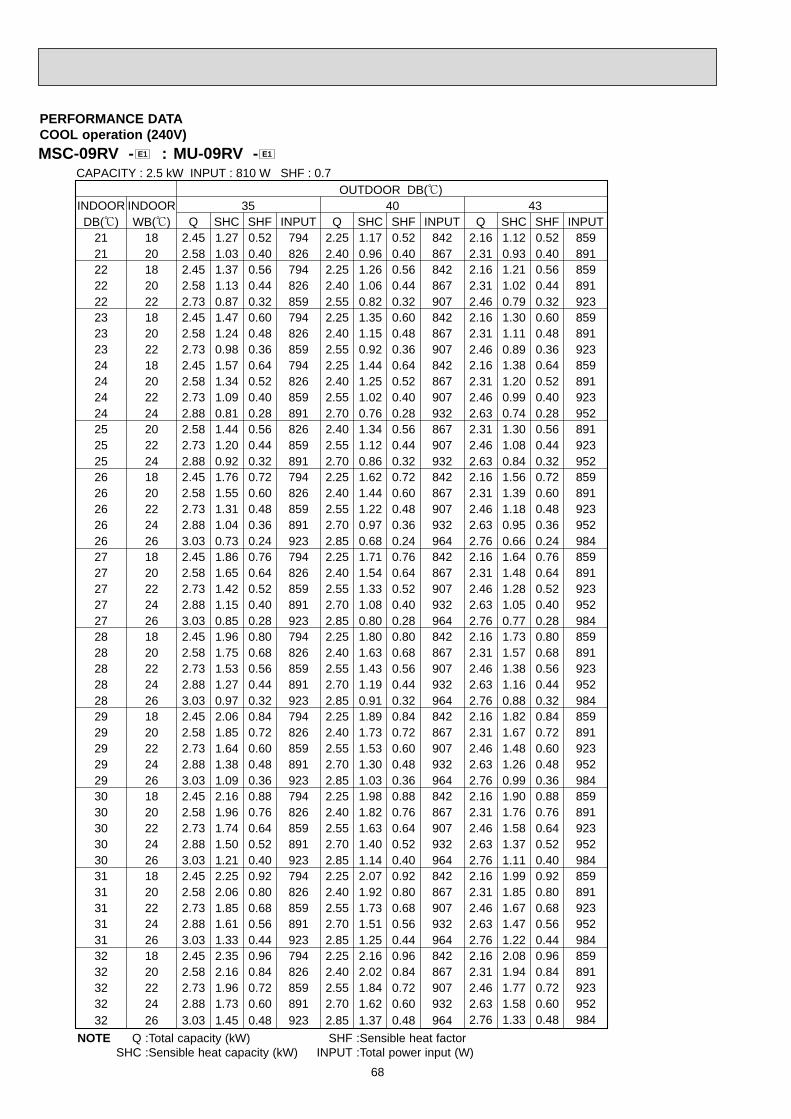
68
MSC-09RV - : MU-09RV - E1E1
PERFORMANCE DATACOOL operation (240V)
OUTDOOR DB(;)INDOOR INDOOR 35 40 43DB(;) WB(;) Q SHC SHF INPUT Q SHC SHF INPUT
21 18 2.45 1.27 0.52 794 2.25 1.17 0.52 84221 20 2.58 1.03 0.40 826 2.40 0.96 0.40 86722 18 2.45 1.37 0.56 794 2.25 1.26 0.56 84222 20 2.58 1.13 0.44 826 2.40 1.06 0.44 86722 22 2.73 0.87 0.32 859 2.55 0.82 0.32 90723 18 2.45 1.47 0.60 794 2.25 1.35 0.60 84223 20 2.58 1.24 0.48 826 2.40 1.15 0.48 86723 22 2.73 0.98 0.36 859 2.55 0.92 0.36 90724 18 2.45 1.57 0.64 794 2.25 1.44 0.64 84224 20 2.58 1.34 0.52 826 2.40 1.25 0.52 86724 22 2.73 1.09 0.40 859 2.55 1.02 0.40 90724 24 2.88 0.81 0.28 891 2.70 0.76 0.28 93225 20 2.58 1.44 0.56 826 2.40 1.34 0.56 86725 22 2.73 1.20 0.44 859 2.55 1.12 0.44 90725 24 2.88 0.92 0.32 891 2.70 0.86 0.32 93226 18 2.45 1.76 0.72 794 2.25 1.62 0.72 84226 20 2.58 1.55 0.60 826 2.40 1.44 0.60 86726 22 2.73 1.31 0.48 859 2.55 1.22 0.48 90726 24 2.88 1.04 0.36 891 2.70 0.97 0.36 93226 26 3.03 0.73 0.24 923 2.85 0.68 0.24 96427 18 2.45 1.86 0.76 794 2.25 1.71 0.76 84227 20 2.58 1.65 0.64 826 2.40 1.54 0.64 86727 22 2.73 1.42 0.52 859 2.55 1.33 0.52 90727 24 2.88 1.15 0.40 891 2.70 1.08 0.40 93227 26 3.03 0.85 0.28 923 2.85 0.80 0.28 96428 18 2.45 1.96 0.80 794 2.25 1.80 0.80 84228 20 2.58 1.75 0.68 826 2.40 1.63 0.68 86728 22 2.73 1.53 0.56 859 2.55 1.43 0.56 90728 24 2.88 1.27 0.44 891 2.70 1.19 0.44 93228 26 3.03 0.97 0.32 923 2.85 0.91 0.32 96429 18 2.45 2.06 0.84 794 2.25 1.89 0.84 84229 20 2.58 1.85 0.72 826 2.40 1.73 0.72 86729 22 2.73 1.64 0.60 859 2.55 1.53 0.60 90729 24 2.88 1.38 0.48 891 2.70 1.30 0.48 93229 26 3.03 1.09 0.36 923 2.85 1.03 0.36 96430 18 2.45 2.16 0.88 794 2.25 1.98 0.88 84230 20 2.58 1.96 0.76 826 2.40 1.82 0.76 86730 22 2.73 1.74 0.64 859 2.55 1.63 0.64 90730 24 2.88 1.50 0.52 891 2.70 1.40 0.52 93230 26 3.03 1.21 0.40 923 2.85 1.14 0.40 96431 18 2.45 2.25 0.92 794 2.25 2.07 0.92 84231 20 2.58 2.06 0.80 826 2.40 1.92 0.80 86731 22 2.73 1.85 0.68 859 2.55 1.73 0.68 90731 24 2.88 1.61 0.56 891 2.70 1.51 0.56 93231 26 3.03 1.33 0.44 923 2.85 1.25 0.44 96432 18 2.45 2.35 0.96 794 2.25 2.16 0.96 84232 20 2.58 2.16 0.84 826 2.40 2.02 0.84 86732 22 2.73 1.96 0.72 859 2.55 1.84 0.72 90732 24 2.88 1.73 0.60 891 2.70 1.62 0.60 93232 26 3.03 1.45 0.48 923 2.85 1.37 0.48 964
CAPACITY : 2.5 kW INPUT : 810 W SHF : 0.7
Q SHC SHF INPUT2.16 1.12 0.52 8592.31 0.93 0.40 8912.16 1.21 0.56 8592.31 1.02 0.44 8912.46 0.79 0.32 9232.16 1.30 0.60 8592.31 1.11 0.48 8912.46 0.89 0.36 9232.16 1.38 0.64 8592.31 1.20 0.52 8912.46 0.99 0.40 9232.63 0.74 0.28 9522.31 1.30 0.56 8912.46 1.08 0.44 9232.63 0.84 0.32 9522.16 1.56 0.72 8592.31 1.39 0.60 8912.46 1.18 0.48 9232.63 0.95 0.36 9522.76 0.66 0.24 9842.16 1.64 0.76 8592.31 1.48 0.64 8912.46 1.28 0.52 9232.63 1.05 0.40 9522.76 0.77 0.28 9842.16 1.73 0.80 8592.31 1.57 0.68 8912.46 1.38 0.56 9232.63 1.16 0.44 9522.76 0.88 0.32 9842.16 1.82 0.84 8592.31 1.67 0.72 8912.46 1.48 0.60 9232.63 1.26 0.48 9522.76 0.99 0.36 9842.16 1.90 0.88 8592.31 1.76 0.76 8912.46 1.58 0.64 9232.63 1.37 0.52 9522.76 1.11 0.40 9842.16 1.99 0.92 8592.31 1.85 0.80 8912.46 1.67 0.68 9232.63 1.47 0.56 9522.76 1.22 0.44 9842.16 2.08 0.96 8592.31 1.94 0.84 8912.46 1.77 0.72 9232.63 1.58 0.60 9522.76 1.33 0.48 984
NOTE Q :Total capacity (kW) SHF :Sensible heat factorSHC :Sensible heat capacity (kW) INPUT :Total power input (W)

69
MSC-12RV - : MU-12RV - E1E1
PERFORMANCE DATACOOL operation (220V)
OUTDOOR DB(;)INDOOR INDOOR 21 25 27 30DB(;) WB(;) Q SHC SHF INPUT Q SHC SHF INPUT Q SHC SHF INPUT Q SHC SHF INPUT
21 18 4.11 2.02 0.49 1048 3.94 1.93 0.49 1100 3.78 1.85 0.49 1153 3.64 1.78 0.49 120521 20 4.29 1.59 0.37 1100 4.11 1.52 0.37 1166 3.99 1.48 0.37 1192 3.85 1.42 0.37 124522 18 4.11 2.18 0.53 1048 3.94 2.09 0.53 1100 3.78 2.00 0.53 1153 3.64 1.93 0.53 120522 20 4.29 1.76 0.41 1100 4.11 1.69 0.41 1166 3.99 1.64 0.41 1192 3.85 1.58 0.41 124522 22 4.46 1.29 0.29 1140 4.31 1.25 0.29 1212 4.20 1.22 0.29 1245 4.03 1.17 0.29 129723 18 4.11 2.34 0.57 1048 3.94 2.24 0.57 1100 3.78 2.15 0.57 1153 3.64 2.07 0.57 120523 20 4.29 1.93 0.45 1100 4.11 1.85 0.45 1166 3.99 1.80 0.45 1192 3.85 1.73 0.45 124523 22 4.46 1.47 0.33 1140 4.31 1.42 0.33 1212 4.20 1.39 0.33 1245 4.03 1.33 0.33 129724 18 4.11 2.51 0.61 1048 3.94 2.40 0.61 1100 3.78 2.31 0.61 1153 3.64 2.22 0.61 120524 20 4.29 2.10 0.49 1100 4.11 2.02 0.49 1166 3.99 1.96 0.49 1192 3.85 1.89 0.49 124524 22 4.46 1.65 0.37 1140 4.31 1.59 0.37 1212 4.20 1.55 0.37 1245 4.03 1.49 0.37 129724 24 4.69 1.17 0.25 1192 4.52 1.13 0.25 1258 4.41 1.10 0.25 1297 4.27 1.07 0.25 136225 20 4.29 2.27 0.53 1100 4.11 2.18 0.53 1166 3.99 2.11 0.53 1192 3.85 2.04 0.53 124525 22 4.46 1.83 0.41 1140 4.31 1.77 0.41 1212 4.20 1.72 0.41 1245 4.03 1.65 0.41 129725 24 4.69 1.36 0.29 1192 4.52 1.31 0.29 1258 4.41 1.28 0.29 1297 4.27 1.24 0.29 136226 18 4.11 2.84 0.69 1048 3.94 2.72 0.69 1100 3.78 2.61 0.69 1153 3.64 2.51 0.69 120526 20 4.29 2.44 0.57 1100 4.11 2.34 0.57 1166 3.99 2.27 0.57 1192 3.85 2.19 0.57 124526 22 4.46 2.01 0.45 1140 4.31 1.94 0.45 1212 4.20 1.89 0.45 1245 4.03 1.81 0.45 129726 24 4.69 1.55 0.33 1192 4.52 1.49 0.33 1258 4.41 1.46 0.33 1297 4.27 1.41 0.33 136226 26 4.83 1.01 0.21 1258 4.69 0.98 0.21 1323 4.62 0.97 0.21 1362 4.48 0.94 0.21 140227 18 4.11 3.00 0.73 1048 3.94 2.87 0.73 1100 3.78 2.76 0.73 1153 3.64 2.66 0.73 120527 20 4.29 2.62 0.61 1100 4.11 2.51 0.61 1166 3.99 2.43 0.61 1192 3.85 2.35 0.61 124527 22 4.46 2.19 0.49 1140 4.31 2.11 0.49 1212 4.20 2.06 0.49 1245 4.03 1.97 0.49 129727 24 4.69 1.74 0.37 1192 4.52 1.67 0.37 1258 4.41 1.63 0.37 1297 4.27 1.58 0.37 136227 26 4.83 1.21 0.25 1258 4.69 1.17 0.25 1323 4.62 1.16 0.25 1362 4.48 1.12 0.25 140228 18 4.11 3.17 0.77 1048 3.94 3.03 0.77 1100 3.78 2.91 0.77 1153 3.64 2.80 0.77 120528 20 4.29 2.79 0.65 1100 4.11 2.67 0.65 1166 3.99 2.59 0.65 1192 3.85 2.50 0.65 124528 22 4.46 2.37 0.53 1140 4.31 2.28 0.53 1212 4.20 2.23 0.53 1245 4.03 2.13 0.53 129728 24 4.69 1.92 0.41 1192 4.52 1.85 0.41 1258 4.41 1.81 0.41 1297 4.27 1.75 0.41 136228 26 4.83 1.40 0.29 1258 4.69 1.36 0.29 1323 4.62 1.34 0.29 1362 4.48 1.30 0.29 140229 18 4.11 3.33 0.81 1048 3.94 3.19 0.81 1100 3.78 3.06 0.81 1153 3.64 2.95 0.81 120529 20 4.29 2.96 0.69 1100 4.11 2.84 0.69 1166 3.99 2.75 0.69 1192 3.85 2.66 0.69 124529 22 4.46 2.54 0.57 1140 4.31 2.45 0.57 1212 4.20 2.39 0.57 1245 4.03 2.29 0.57 129729 24 4.69 2.11 0.45 1192 4.52 2.03 0.45 1258 4.41 1.98 0.45 1297 4.27 1.92 0.45 136229 26 4.83 1.59 0.33 1258 4.69 1.55 0.33 1323 4.62 1.52 0.33 1362 4.48 1.48 0.33 140230 18 4.11 3.50 0.85 1048 3.94 3.35 0.85 1100 3.78 3.21 0.85 1153 3.64 3.09 0.85 120530 20 4.29 3.13 0.73 1100 4.11 3.00 0.73 1166 3.99 2.91 0.73 1192 3.85 2.81 0.73 124530 22 4.46 2.72 0.61 1140 4.31 2.63 0.61 1212 4.20 2.56 0.61 1245 4.03 2.46 0.61 129730 24 4.69 2.30 0.49 1192 4.52 2.21 0.49 1258 4.41 2.16 0.49 1297 4.27 2.09 0.49 136230 26 4.83 1.79 0.37 1258 4.69 1.74 0.37 1323 4.62 1.71 0.37 1362 4.48 1.66 0.37 140231 18 4.11 3.66 0.89 1048 3.94 3.50 0.89 1100 3.78 3.36 0.89 1153 3.64 3.24 0.89 120531 20 4.29 3.30 0.77 1100 4.11 3.17 0.77 1166 3.99 3.07 0.77 1192 3.85 2.96 0.77 124531 22 4.46 2.90 0.65 1140 4.31 2.80 0.65 1212 4.20 2.73 0.65 1245 4.03 2.62 0.65 129731 24 4.69 2.49 0.53 1192 4.52 2.39 0.53 1258 4.41 2.34 0.53 1297 4.27 2.26 0.53 136231 26 4.83 1.98 0.41 1258 4.69 1.92 0.41 1323 4.62 1.89 0.41 1362 4.48 1.84 0.41 140232 18 4.11 3.82 0.93 1048 3.94 3.66 0.93 1100 3.78 3.52 0.93 1153 3.64 3.39 0.93 120532 20 4.29 3.47 0.81 1100 4.11 3.33 0.81 1166 3.99 3.23 0.81 1192 3.85 3.12 0.81 124532 22 4.46 3.08 0.69 1140 4.31 2.97 0.69 1212 4.20 2.90 0.69 1245 4.03 2.78 0.69 129732 24 4.69 2.67 0.57 1192 4.52 2.57 0.57 1258 4.41 2.51 0.57 1297 4.27 2.43 0.57 136232 26 4.83 2.17 0.45 1258 4.69 2.11 0.45 1323 4.62 2.08 0.45 1362 4.48 2.02 0.45 1402
CAPACITY : 3.5 kW INPUT : 1310 W SHF : 0.67
NOTE Q :Total capacity (kW) SHF :Sensible heat factorSHC :Sensible heat capacity (kW) INPUT :Total power input (W)

70
MSC-12RV - : MU-12RV - E1E1
PERFORMANCE DATACOOL operation (220V)
OUTDOOR DB(;)INDOOR INDOOR 35 40 43DB(;) WB(;) Q SHC SHF INPUT Q SHC SHF INPUT
21 18 3.43 1.68 0.49 1284 3.15 1.54 0.49 136221 20 3.61 1.33 0.37 1336 3.36 1.24 0.37 140222 18 3.43 1.82 0.53 1284 3.15 1.67 0.53 136222 20 3.61 1.48 0.41 1336 3.36 1.38 0.41 140222 22 3.82 1.11 0.29 1389 3.57 1.04 0.29 146723 18 3.43 1.96 0.57 1284 3.15 1.80 0.57 136223 20 3.61 1.62 0.45 1336 3.36 1.51 0.45 140223 22 3.82 1.26 0.33 1389 3.57 1.18 0.33 146724 18 3.43 2.09 0.61 1284 3.15 1.92 0.61 136224 20 3.61 1.77 0.49 1336 3.36 1.65 0.49 140224 22 3.82 1.41 0.37 1389 3.57 1.32 0.37 146724 24 4.03 1.01 0.25 1441 3.78 0.95 0.25 150725 20 3.61 1.91 0.53 1336 3.36 1.78 0.53 140225 22 3.82 1.56 0.41 1389 3.57 1.46 0.41 146725 24 4.03 1.17 0.29 1441 3.78 1.10 0.29 150726 18 3.43 2.37 0.69 1284 3.15 2.17 0.69 136226 20 3.61 2.05 0.57 1336 3.36 1.92 0.57 140226 22 3.82 1.72 0.45 1389 3.57 1.61 0.45 146726 24 4.03 1.33 0.33 1441 3.78 1.25 0.33 150726 26 4.24 0.89 0.21 1493 3.99 0.84 0.21 155927 18 3.43 2.50 0.73 1284 3.15 2.30 0.73 136227 20 3.61 2.20 0.61 1336 3.36 2.05 0.61 140227 22 3.82 1.87 0.49 1389 3.57 1.75 0.49 146727 24 4.03 1.49 0.37 1441 3.78 1.40 0.37 150727 26 4.24 1.06 0.25 1493 3.99 1.00 0.25 155928 18 3.43 2.64 0.77 1284 3.15 2.43 0.77 136228 20 3.61 2.34 0.65 1336 3.36 2.18 0.65 140228 22 3.82 2.02 0.53 1389 3.57 1.89 0.53 146728 24 4.03 1.65 0.41 1441 3.78 1.55 0.41 150728 26 4.24 1.23 0.29 1493 3.99 1.16 0.29 155929 18 3.43 2.78 0.81 1284 3.15 2.55 0.81 136229 20 3.61 2.49 0.69 1336 3.36 2.32 0.69 140229 22 3.82 2.17 0.57 1389 3.57 2.03 0.57 146729 24 4.03 1.81 0.45 1441 3.78 1.70 0.45 150729 26 4.24 1.40 0.33 1493 3.99 1.32 0.33 155930 18 3.43 2.92 0.85 1284 3.15 2.68 0.85 136230 20 3.61 2.63 0.73 1336 3.36 2.45 0.73 140230 22 3.82 2.33 0.61 1389 3.57 2.18 0.61 146730 24 4.03 1.97 0.49 1441 3.78 1.85 0.49 150730 26 4.24 1.57 0.37 1493 3.99 1.48 0.37 155931 18 3.43 3.05 0.89 1284 3.15 2.80 0.89 136231 20 3.61 2.78 0.77 1336 3.36 2.59 0.77 140231 22 3.82 2.48 0.65 1389 3.57 2.32 0.65 146731 24 4.03 2.13 0.53 1441 3.78 2.00 0.53 150731 26 4.24 1.74 0.41 1493 3.99 1.64 0.41 155932 18 3.43 3.19 0.93 1284 3.15 2.93 0.93 136232 20 3.61 2.92 0.81 1336 3.36 2.72 0.81 140232 22 3.82 2.63 0.69 1389 3.57 2.46 0.69 146732 24 4.03 2.29 0.57 1441 3.78 2.15 0.57 150732 26 4.24 1.91 0.45 1493 3.99 1.80 0.45 1559
CAPACITY : 3.5 kW INPUT : 1310 W SHF : 0.67
Q SHC SHF INPUT3.03 1.48 0.49 13893.24 1.20 0.37 14413.03 1.60 0.53 13893.24 1.33 0.41 14413.45 1.00 0.29 14933.03 1.73 0.57 13893.24 1.46 0.45 14413.45 1.14 0.33 14933.03 1.85 0.61 13893.24 1.59 0.49 14413.45 1.28 0.37 14933.68 0.92 0.25 15393.24 1.72 0.53 14413.45 1.41 0.41 14933.68 1.07 0.29 15393.03 2.09 0.69 13893.24 1.85 0.57 14413.45 1.55 0.45 14933.68 1.21 0.33 15393.87 0.81 0.21 15923.03 2.21 0.73 13893.24 1.97 0.61 14413.45 1.69 0.49 14933.68 1.36 0.37 15393.87 0.97 0.25 15923.03 2.33 0.77 13893.24 2.10 0.65 14413.45 1.83 0.53 14933.68 1.51 0.41 15393.87 1.12 0.29 15923.03 2.45 0.81 13893.24 2.23 0.69 14413.45 1.97 0.57 14933.68 1.65 0.45 15393.87 1.28 0.33 15923.03 2.57 0.85 13893.24 2.36 0.73 14413.45 2.10 0.61 14933.68 1.80 0.49 15393.87 1.43 0.37 15923.03 2.69 0.89 13893.24 2.49 0.77 14413.45 2.24 0.65 14933.68 1.95 0.53 15393.87 1.59 0.41 15923.03 2.82 0.93 13893.24 2.62 0.81 14413.45 2.38 0.69 14933.68 2.09 0.57 15393.87 1.74 0.45 1592
NOTE Q :Total capacity (kW) SHF :Sensible heat factorSHC :Sensible heat capacity (kW) INPUT :Total power input (W)

71
MSC-12RV - : MU-12RV - E1E1
PERFORMANCE DATACOOL operation (240V)
OUTDOOR DB(;)INDOOR INDOOR 21 25 27 30DB(;) WB(;) Q SHC SHF INPUT Q SHC SHF INPUT Q SHC SHF INPUT Q SHC SHF INPUT
21 18 4.11 2.02 0.49 1112 3.94 1.93 0.49 1168 3.78 1.85 0.49 1223 3.64 1.78 0.49 127921 20 4.29 1.59 0.37 1168 4.11 1.52 0.37 1237 3.99 1.48 0.37 1265 3.85 1.42 0.37 132122 18 4.11 2.18 0.53 1112 3.94 2.09 0.53 1168 3.78 2.00 0.53 1223 3.64 1.93 0.53 127922 20 4.29 1.76 0.41 1168 4.11 1.69 0.41 1237 3.99 1.64 0.41 1265 3.85 1.58 0.41 132122 22 4.46 1.29 0.29 1209 4.31 1.25 0.29 1286 4.20 1.22 0.29 1321 4.03 1.17 0.29 137623 18 4.11 2.34 0.57 1112 3.94 2.24 0.57 1168 3.78 2.15 0.57 1223 3.64 2.07 0.57 127923 20 4.29 1.93 0.45 1168 4.11 1.85 0.45 1237 3.99 1.80 0.45 1265 3.85 1.73 0.45 132123 22 4.46 1.47 0.33 1209 4.31 1.42 0.33 1286 4.20 1.39 0.33 1321 4.03 1.33 0.33 137624 18 4.11 2.51 0.61 1112 3.94 2.40 0.61 1168 3.78 2.31 0.61 1223 3.64 2.22 0.61 127924 20 4.29 2.10 0.49 1168 4.11 2.02 0.49 1237 3.99 1.96 0.49 1265 3.85 1.89 0.49 132124 22 4.46 1.65 0.37 1209 4.31 1.59 0.37 1286 4.20 1.55 0.37 1321 4.03 1.49 0.37 137624 24 4.69 1.17 0.25 1265 4.52 1.13 0.25 1334 4.41 1.10 0.25 1376 4.27 1.07 0.25 144625 20 4.29 2.27 0.53 1168 4.11 2.18 0.53 1237 3.99 2.11 0.53 1265 3.85 2.04 0.53 132125 22 4.46 1.83 0.41 1209 4.31 1.77 0.41 1286 4.20 1.72 0.41 1321 4.03 1.65 0.41 137625 24 4.69 1.36 0.29 1265 4.52 1.31 0.29 1334 4.41 1.28 0.29 1376 4.27 1.24 0.29 144626 18 4.11 2.84 0.69 1112 3.94 2.72 0.69 1168 3.78 2.61 0.69 1223 3.64 2.51 0.69 127926 20 4.29 2.44 0.57 1168 4.11 2.34 0.57 1237 3.99 2.27 0.57 1265 3.85 2.19 0.57 132126 22 4.46 2.01 0.45 1209 4.31 1.94 0.45 1286 4.20 1.89 0.45 1321 4.03 1.81 0.45 137626 24 4.69 1.55 0.33 1265 4.52 1.49 0.33 1334 4.41 1.46 0.33 1376 4.27 1.41 0.33 144626 26 4.83 1.01 0.21 1334 4.69 0.98 0.21 1404 4.62 0.97 0.21 1446 4.48 0.94 0.21 148727 18 4.11 3.00 0.73 1112 3.94 2.87 0.73 1168 3.78 2.76 0.73 1223 3.64 2.66 0.73 127927 20 4.29 2.62 0.61 1168 4.11 2.51 0.61 1237 3.99 2.43 0.61 1265 3.85 2.35 0.61 132127 22 4.46 2.19 0.49 1209 4.31 2.11 0.49 1286 4.20 2.06 0.49 1321 4.03 1.97 0.49 137627 24 4.69 1.74 0.37 1265 4.52 1.67 0.37 1334 4.41 1.63 0.37 1376 4.27 1.58 0.37 144627 26 4.83 1.21 0.25 1334 4.69 1.17 0.25 1404 4.62 1.16 0.25 1446 4.48 1.12 0.25 148728 18 4.11 3.17 0.77 1112 3.94 3.03 0.77 1168 3.78 2.91 0.77 1223 3.64 2.80 0.77 127928 20 4.29 2.79 0.65 1168 4.11 2.67 0.65 1237 3.99 2.59 0.65 1265 3.85 2.50 0.65 132128 22 4.46 2.37 0.53 1209 4.31 2.28 0.53 1286 4.20 2.23 0.53 1321 4.03 2.13 0.53 137628 24 4.69 1.92 0.41 1265 4.52 1.85 0.41 1334 4.41 1.81 0.41 1376 4.27 1.75 0.41 144628 26 4.83 1.40 0.29 1334 4.69 1.36 0.29 1404 4.62 1.34 0.29 1446 4.48 1.30 0.29 148729 18 4.11 3.33 0.81 1112 3.94 3.19 0.81 1168 3.78 3.06 0.81 1223 3.64 2.95 0.81 127929 20 4.29 2.96 0.69 1168 4.11 2.84 0.69 1237 3.99 2.75 0.69 1265 3.85 2.66 0.69 132129 22 4.46 2.54 0.57 1209 4.31 2.45 0.57 1286 4.20 2.39 0.57 1321 4.03 2.29 0.57 137629 24 4.69 2.11 0.45 1265 4.52 2.03 0.45 1334 4.41 1.98 0.45 1376 4.27 1.92 0.45 144629 26 4.83 1.59 0.33 1334 4.69 1.55 0.33 1404 4.62 1.52 0.33 1446 4.48 1.48 0.33 148730 18 4.11 3.50 0.85 1112 3.94 3.35 0.85 1168 3.78 3.21 0.85 1223 3.64 3.09 0.85 127930 20 4.29 3.13 0.73 1168 4.11 3.00 0.73 1237 3.99 2.91 0.73 1265 3.85 2.81 0.73 132130 22 4.46 2.72 0.61 1209 4.31 2.63 0.61 1286 4.20 2.56 0.61 1321 4.03 2.46 0.61 137630 24 4.69 2.30 0.49 1265 4.52 2.21 0.49 1334 4.41 2.16 0.49 1376 4.27 2.09 0.49 144630 26 4.83 1.79 0.37 1334 4.69 1.74 0.37 1404 4.62 1.71 0.37 1446 4.48 1.66 0.37 148731 18 4.11 3.66 0.89 1112 3.94 3.50 0.89 1168 3.78 3.36 0.89 1223 3.64 3.24 0.89 127931 20 4.29 3.30 0.77 1168 4.11 3.17 0.77 1237 3.99 3.07 0.77 1265 3.85 2.96 0.77 132131 22 4.46 2.90 0.65 1209 4.31 2.80 0.65 1286 4.20 2.73 0.65 1321 4.03 2.62 0.65 137631 24 4.69 2.49 0.53 1265 4.52 2.39 0.53 1334 4.41 2.34 0.53 1376 4.27 2.26 0.53 144631 26 4.83 1.98 0.41 1334 4.69 1.92 0.41 1404 4.62 1.89 0.41 1446 4.48 1.84 0.41 148732 18 4.11 3.82 0.93 1112 3.94 3.66 0.93 1168 3.78 3.52 0.93 1223 3.64 3.39 0.93 127932 20 4.29 3.47 0.81 1168 4.11 3.33 0.81 1237 3.99 3.23 0.81 1265 3.85 3.12 0.81 132132 22 4.46 3.08 0.69 1209 4.31 2.97 0.69 1286 4.20 2.90 0.69 1321 4.03 2.78 0.69 137632 24 4.69 2.67 0.57 1265 4.52 2.57 0.57 1334 4.41 2.51 0.57 1376 4.27 2.43 0.57 144632 26 4.83 2.17 0.45 1334 4.69 2.11 0.45 1404 4.62 2.08 0.45 1446 4.48 2.02 0.45 1487
CAPACITY : 3.5 kW INPUT : 1390 W SHF : 0.67
NOTE Q :Total capacity (kW) SHF :Sensible heat factorSHC :Sensible heat capacity (kW) INPUT :Total power input (W)

72
MSC-12RV - : MU-12RV - E1E1
PERFORMANCE DATACOOL operation (240V)
OUTDOOR DB(;)INDOOR INDOOR 35 40 43DB(;) WB(;) Q SHC SHF INPUT Q SHC SHF INPUT
21 18 3.43 1.68 0.49 1362 3.15 1.54 0.49 144621 20 3.61 1.33 0.37 1418 3.36 1.24 0.37 148722 18 3.43 1.82 0.53 1362 3.15 1.67 0.53 144622 20 3.61 1.48 0.41 1418 3.36 1.38 0.41 148722 22 3.82 1.11 0.29 1473 3.57 1.04 0.29 155723 18 3.43 1.96 0.57 1362 3.15 1.80 0.57 144623 20 3.61 1.62 0.45 1418 3.36 1.51 0.45 148723 22 3.82 1.26 0.33 1473 3.57 1.18 0.33 155724 18 3.43 2.09 0.61 1362 3.15 1.92 0.61 144624 20 3.61 1.77 0.49 1418 3.36 1.65 0.49 148724 22 3.82 1.41 0.37 1473 3.57 1.32 0.37 155724 24 4.03 1.01 0.25 1529 3.78 0.95 0.25 159925 20 3.61 1.91 0.53 1418 3.36 1.78 0.53 148725 22 3.82 1.56 0.41 1473 3.57 1.46 0.41 155725 24 4.03 1.17 0.29 1529 3.78 1.10 0.29 159926 18 3.43 2.37 0.69 1362 3.15 2.17 0.69 144626 20 3.61 2.05 0.57 1418 3.36 1.92 0.57 148726 22 3.82 1.72 0.45 1473 3.57 1.61 0.45 155726 24 4.03 1.33 0.33 1529 3.78 1.25 0.33 159926 26 4.24 0.89 0.21 1585 3.99 0.84 0.21 165427 18 3.43 2.50 0.73 1362 3.15 2.30 0.73 144627 20 3.61 2.20 0.61 1418 3.36 2.05 0.61 148727 22 3.82 1.87 0.49 1473 3.57 1.75 0.49 155727 24 4.03 1.49 0.37 1529 3.78 1.40 0.37 159927 26 4.24 1.06 0.25 1585 3.99 1.00 0.25 165428 18 3.43 2.64 0.77 1362 3.15 2.43 0.77 144628 20 3.61 2.34 0.65 1418 3.36 2.18 0.65 148728 22 3.82 2.02 0.53 1473 3.57 1.89 0.53 155728 24 4.03 1.65 0.41 1529 3.78 1.55 0.41 159928 26 4.24 1.23 0.29 1585 3.99 1.16 0.29 165429 18 3.43 2.78 0.81 1362 3.15 2.55 0.81 144629 20 3.61 2.49 0.69 1418 3.36 2.32 0.69 148729 22 3.82 2.17 0.57 1473 3.57 2.03 0.57 155729 24 4.03 1.81 0.45 1529 3.78 1.70 0.45 159929 26 4.24 1.40 0.33 1585 3.99 1.32 0.33 165430 18 3.43 2.92 0.85 1362 3.15 2.68 0.85 144630 20 3.61 2.63 0.73 1418 3.36 2.45 0.73 148730 22 3.82 2.33 0.61 1473 3.57 2.18 0.61 155730 24 4.03 1.97 0.49 1529 3.78 1.85 0.49 159930 26 4.24 1.57 0.37 1585 3.99 1.48 0.37 165431 18 3.43 3.05 0.89 1362 3.15 2.80 0.89 144631 20 3.61 2.78 0.77 1418 3.36 2.59 0.77 148731 22 3.82 2.48 0.65 1473 3.57 2.32 0.65 155731 24 4.03 2.13 0.53 1529 3.78 2.00 0.53 159931 26 4.24 1.74 0.41 1585 3.99 1.64 0.41 165432 18 3.43 3.19 0.93 1362 3.15 2.93 0.93 144632 20 3.61 2.92 0.81 1418 3.36 2.72 0.81 148732 22 3.82 2.63 0.69 1473 3.57 2.46 0.69 155732 24 4.03 2.29 0.57 1529 3.78 2.15 0.57 159932 26 4.24 1.91 0.45 1585 3.99 1.80 0.45 1654
CAPACITY : 3.5 kW INPUT : 1390 W SHF : 0.67
Q SHC SHF INPUT3.03 1.48 0.49 14733.24 1.20 0.37 15293.03 1.60 0.53 14733.24 1.33 0.41 15293.45 1.00 0.29 15853.03 1.73 0.57 14733.24 1.46 0.45 15293.45 1.14 0.33 15853.03 1.85 0.61 14733.24 1.59 0.49 15293.45 1.28 0.37 15853.68 0.92 0.25 16333.24 1.72 0.53 15293.45 1.41 0.41 15853.68 1.07 0.29 16333.03 2.09 0.69 14733.24 1.85 0.57 15293.45 1.55 0.45 15853.68 1.21 0.33 16333.87 0.81 0.21 16893.03 2.21 0.73 14733.24 1.97 0.61 15293.45 1.69 0.49 15853.68 1.36 0.37 16333.87 0.97 0.25 16893.03 2.33 0.77 14733.24 2.10 0.65 15293.45 1.83 0.53 15853.68 1.51 0.41 16333.87 1.12 0.29 16893.03 2.45 0.81 14733.24 2.23 0.69 15293.45 1.97 0.57 15853.68 1.65 0.45 16333.87 1.28 0.33 16893.03 2.57 0.85 14733.24 2.36 0.73 15293.45 2.10 0.61 15853.68 1.80 0.49 16333.87 1.43 0.37 16893.03 2.69 0.89 14733.24 2.49 0.77 15293.45 2.24 0.65 15853.68 1.95 0.53 16333.87 1.59 0.41 16893.03 2.82 0.93 14733.24 2.62 0.81 15293.45 2.38 0.69 15853.68 2.09 0.57 16333.87 1.74 0.45 1689
NOTE Q :Total capacity (kW) SHF :Sensible heat factorSHC :Sensible heat capacity (kW) INPUT :Total power input (W)

73
MSC-07RV - : MUH-07RV - E1E1
PERFORMANCE DATACOOL operation (220V)
OUTDOOR DB(;)INDOOR INDOOR 21 25 27 30DB(;) WB(;) Q SHC SHF INPUT Q SHC SHF INPUT Q SHC SHF INPUT Q SHC SHF INPUT
21 18 2.59 1.45 0.56 568 2.48 1.39 0.56 596 2.38 1.33 0.56 625 2.29 1.28 0.56 65321 20 2.70 1.19 0.44 596 2.59 1.14 0.44 632 2.51 1.10 0.44 646 2.42 1.06 0.44 67522 18 2.59 1.55 0.60 568 2.48 1.49 0.60 596 2.38 1.43 0.60 625 2.29 1.37 0.60 65322 20 2.70 1.29 0.48 596 2.59 1.24 0.48 632 2.51 1.20 0.48 646 2.42 1.16 0.48 67522 22 2.81 1.01 0.36 618 2.71 0.97 0.36 657 2.64 0.95 0.36 675 2.53 0.91 0.36 70323 18 2.59 1.65 0.64 568 2.48 1.58 0.64 596 2.38 1.52 0.64 625 2.29 1.46 0.64 65323 20 2.70 1.40 0.52 596 2.59 1.34 0.52 632 2.51 1.30 0.52 646 2.42 1.26 0.52 67523 22 2.81 1.12 0.40 618 2.71 1.08 0.40 657 2.64 1.06 0.40 675 2.53 1.01 0.40 70324 18 2.59 1.76 0.68 568 2.48 1.68 0.68 596 2.38 1.62 0.68 625 2.29 1.56 0.68 65324 20 2.70 1.51 0.56 596 2.59 1.45 0.56 632 2.51 1.40 0.56 646 2.42 1.36 0.56 67524 22 2.81 1.23 0.44 618 2.71 1.19 0.44 657 2.64 1.16 0.44 675 2.53 1.11 0.44 70324 24 2.95 0.94 0.32 646 2.84 0.91 0.32 682 2.77 0.89 0.32 703 2.68 0.86 0.32 73825 20 2.70 1.62 0.60 596 2.59 1.55 0.60 632 2.51 1.50 0.60 646 2.42 1.45 0.60 67525 22 2.81 1.35 0.48 618 2.71 1.30 0.48 657 2.64 1.27 0.48 675 2.53 1.21 0.48 70325 24 2.95 1.06 0.36 646 2.84 1.02 0.36 682 2.77 1.00 0.36 703 2.68 0.97 0.36 73826 18 2.59 1.96 0.76 568 2.48 1.88 0.76 596 2.38 1.81 0.76 625 2.29 1.74 0.76 65326 20 2.70 1.72 0.64 596 2.59 1.65 0.64 632 2.51 1.61 0.64 646 2.42 1.55 0.64 67526 22 2.81 1.46 0.52 618 2.71 1.41 0.52 657 2.64 1.37 0.52 675 2.53 1.32 0.52 70326 24 2.95 1.18 0.40 646 2.84 1.14 0.40 682 2.77 1.11 0.40 703 2.68 1.07 0.40 73826 26 3.04 0.85 0.28 682 2.95 0.83 0.28 717 2.90 0.81 0.28 738 2.82 0.79 0.28 76027 18 2.59 2.07 0.80 568 2.48 1.98 0.80 596 2.38 1.90 0.80 625 2.29 1.83 0.80 65327 20 2.70 1.83 0.68 596 2.59 1.76 0.68 632 2.51 1.71 0.68 646 2.42 1.65 0.68 67527 22 2.81 1.57 0.56 618 2.71 1.52 0.56 657 2.64 1.48 0.56 675 2.53 1.42 0.56 70327 24 2.95 1.30 0.44 646 2.84 1.25 0.44 682 2.77 1.22 0.44 703 2.68 1.18 0.44 73827 26 3.04 0.97 0.32 682 2.95 0.94 0.32 717 2.90 0.93 0.32 738 2.82 0.90 0.32 76028 18 2.59 2.17 0.84 568 2.48 2.08 0.84 596 2.38 2.00 0.84 625 2.29 1.92 0.84 65328 20 2.70 1.94 0.72 596 2.59 1.86 0.72 632 2.51 1.81 0.72 646 2.42 1.74 0.72 67528 22 2.81 1.68 0.60 618 2.71 1.62 0.60 657 2.64 1.58 0.60 675 2.53 1.52 0.60 70328 24 2.95 1.42 0.48 646 2.84 1.36 0.48 682 2.77 1.33 0.48 703 2.68 1.29 0.48 73828 26 3.04 1.09 0.36 682 2.95 1.06 0.36 717 2.90 1.05 0.36 738 2.82 1.01 0.36 76029 18 2.59 2.27 0.88 568 2.48 2.18 0.88 596 2.38 2.09 0.88 625 2.29 2.01 0.88 65329 20 2.70 2.05 0.76 596 2.59 1.96 0.76 632 2.51 1.91 0.76 646 2.42 1.84 0.76 67529 22 2.81 1.80 0.64 618 2.71 1.73 0.64 657 2.64 1.69 0.64 675 2.53 1.62 0.64 70329 24 2.95 1.53 0.52 646 2.84 1.48 0.52 682 2.77 1.44 0.52 703 2.68 1.40 0.52 73829 26 3.04 1.21 0.40 682 2.95 1.18 0.40 717 2.90 1.16 0.40 738 2.82 1.13 0.40 76030 18 2.59 2.38 0.92 568 2.48 2.28 0.92 596 2.38 2.19 0.92 625 2.29 2.10 0.92 65330 20 2.70 2.16 0.80 596 2.59 2.07 0.80 632 2.51 2.01 0.80 646 2.42 1.94 0.80 67530 22 2.81 1.91 0.68 618 2.71 1.84 0.68 657 2.64 1.80 0.68 675 2.53 1.72 0.68 70330 24 2.95 1.65 0.56 646 2.84 1.59 0.56 682 2.77 1.55 0.56 703 2.68 1.50 0.56 73830 26 3.04 1.34 0.44 682 2.95 1.30 0.44 717 2.90 1.28 0.44 738 2.82 1.24 0.44 76031 18 2.59 2.48 0.96 568 2.48 2.38 0.96 596 2.38 2.28 0.96 625 2.29 2.20 0.96 65331 20 2.70 2.26 0.84 596 2.59 2.17 0.84 632 2.51 2.11 0.84 646 2.42 2.03 0.84 67531 22 2.81 2.02 0.72 618 2.71 1.95 0.72 657 2.64 1.90 0.72 675 2.53 1.82 0.72 70331 24 2.95 1.77 0.60 646 2.84 1.70 0.60 682 2.77 1.66 0.60 703 2.68 1.61 0.60 73831 26 3.04 1.46 0.48 682 2.95 1.42 0.48 717 2.90 1.39 0.48 738 2.82 1.35 0.48 76032 18 2.59 2.59 1.00 568 2.48 2.48 1.00 596 2.38 2.38 1.00 625 2.29 2.29 1.00 65332 20 2.70 2.37 0.88 596 2.59 2.27 0.88 632 2.51 2.21 0.88 646 2.42 2.13 0.88 67532 22 2.81 2.13 0.76 618 2.71 2.06 0.76 657 2.64 2.01 0.76 675 2.53 1.92 0.76 70332 24 2.95 1.89 0.64 646 2.84 1.82 0.64 682 2.77 1.77 0.64 703 2.68 1.72 0.64 73832 26 3.04 1.58 0.52 682 2.95 1.53 0.52 717 2.90 1.51 0.52 738 2.82 1.46 0.52 760
CAPACITY : 2.2 kW INPUT : 710 W SHF : 0.74
NOTE Q :Total capacity (kW) SHF :Sensible heat factorSHC :Sensible heat capacity (kW) INPUT :Total power input (W)

74
MSC-07RV - : MUH-07RV - E1E1
PERFORMANCE DATACOOL operation (220V)
OUTDOOR DB(;)INDOOR INDOOR 35 40 43DB(;) WB(;) Q SHC SHF INPUT Q SHC SHF INPUT
21 18 2.16 1.21 0.56 696 1.98 1.11 0.56 73821 20 2.27 1.00 0.44 724 2.11 0.93 0.44 76022 18 2.16 1.29 0.60 696 1.98 1.19 0.60 73822 20 2.27 1.09 0.48 724 2.11 1.01 0.48 76022 22 2.40 0.86 0.36 753 2.24 0.81 0.36 79523 18 2.16 1.38 0.64 696 1.98 1.27 0.64 73823 20 2.27 1.18 0.52 724 2.11 1.10 0.52 76023 22 2.40 0.96 0.40 753 2.24 0.90 0.40 79524 18 2.16 1.47 0.68 696 1.98 1.35 0.68 73824 20 2.27 1.27 0.56 724 2.11 1.18 0.56 76024 22 2.40 1.06 0.44 753 2.24 0.99 0.44 79524 24 2.53 0.81 0.32 781 2.38 0.76 0.32 81725 20 2.27 1.36 0.60 724 2.11 1.27 0.60 76025 22 2.40 1.15 0.48 753 2.24 1.08 0.48 79525 24 2.53 0.91 0.36 781 2.38 0.86 0.36 81726 18 2.16 1.64 0.76 696 1.98 1.50 0.76 73826 20 2.27 1.45 0.64 724 2.11 1.35 0.64 76026 22 2.40 1.25 0.52 753 2.24 1.17 0.52 79526 24 2.53 1.01 0.40 781 2.38 0.95 0.40 81726 26 2.66 0.75 0.28 809 2.51 0.70 0.28 84527 18 2.16 1.72 0.80 696 1.98 1.58 0.80 73827 20 2.27 1.54 0.68 724 2.11 1.44 0.68 76027 22 2.40 1.34 0.56 753 2.24 1.26 0.56 79527 24 2.53 1.11 0.44 781 2.38 1.05 0.44 81727 26 2.66 0.85 0.32 809 2.51 0.80 0.32 84528 18 2.16 1.81 0.84 696 1.98 1.66 0.84 73828 20 2.27 1.63 0.72 724 2.11 1.52 0.72 76028 22 2.40 1.44 0.60 753 2.24 1.35 0.60 79528 24 2.53 1.21 0.48 781 2.38 1.14 0.48 81728 26 2.66 0.96 0.36 809 2.51 0.90 0.36 84529 18 2.16 1.90 0.88 696 1.98 1.74 0.88 73829 20 2.27 1.72 0.76 724 2.11 1.61 0.76 76029 22 2.40 1.53 0.64 753 2.24 1.44 0.64 79529 24 2.53 1.32 0.52 781 2.38 1.24 0.52 81729 26 2.66 1.06 0.40 809 2.51 1.00 0.40 84530 18 2.16 1.98 0.92 696 1.98 1.82 0.92 73830 20 2.27 1.81 0.80 724 2.11 1.69 0.80 76030 22 2.40 1.63 0.68 753 2.24 1.53 0.68 79530 24 2.53 1.42 0.56 781 2.38 1.33 0.56 81730 26 2.66 1.17 0.44 809 2.51 1.10 0.44 84531 18 2.16 2.07 0.96 696 1.98 1.90 0.96 73831 20 2.27 1.90 0.84 724 2.11 1.77 0.84 76031 22 2.40 1.73 0.72 753 2.24 1.62 0.72 79531 24 2.53 1.52 0.60 781 2.38 1.43 0.60 81731 26 2.66 1.28 0.48 809 2.51 1.20 0.48 84532 18 2.16 2.16 1.00 696 1.98 1.98 1.00 73832 20 2.27 1.99 0.88 724 2.11 1.86 0.88 76032 22 2.40 1.82 0.76 753 2.24 1.71 0.76 79532 24 2.53 1.62 0.64 781 2.38 1.52 0.64 81732 26 2.66 1.38 0.52 809 2.51 1.30 0.52 845
CAPACITY : 2.2 kW INPUT : 710 W SHF : 0.74
Q SHC SHF INPUT1.90 1.07 0.56 7532.04 0.90 0.44 7811.90 1.14 0.60 7532.04 0.98 0.48 7812.17 0.78 0.36 8091.90 1.22 0.64 7532.04 1.06 0.52 7812.17 0.87 0.40 8091.90 1.29 0.68 7532.04 1.14 0.56 7812.17 0.95 0.44 8092.31 0.74 0.32 8342.04 1.22 0.60 7812.17 1.04 0.48 8092.31 0.83 0.36 8341.90 1.45 0.76 7532.04 1.30 0.64 7812.17 1.13 0.52 8092.31 0.92 0.40 8342.43 0.68 0.28 8631.90 1.52 0.80 7532.04 1.38 0.68 7812.17 1.21 0.56 8092.31 1.02 0.44 8342.43 0.78 0.32 8631.90 1.60 0.84 7532.04 1.47 0.72 7812.17 1.30 0.60 8092.31 1.11 0.48 8342.43 0.88 0.36 8631.90 1.67 0.88 7532.04 1.55 0.76 7812.17 1.39 0.64 8092.31 1.20 0.52 8342.43 0.97 0.40 8631.90 1.75 0.92 7532.04 1.63 0.80 7812.17 1.47 0.68 8092.31 1.29 0.56 8342.43 1.07 0.44 8631.90 1.83 0.96 7532.04 1.71 0.84 7812.17 1.56 0.72 8092.31 1.39 0.60 8342.43 1.17 0.48 8631.90 1.90 1.00 7532.04 1.79 0.88 7812.17 1.65 0.76 8092.31 1.48 0.64 8342.43 1.26 0.52 863
NOTE Q :Total capacity (kW) SHF :Sensible heat factorSHC :Sensible heat capacity (kW) INPUT :Total power input (W)

75
MSC-07RV - : MUH-07RV - E1E1
PERFORMANCE DATACOOL operation (240V)
OUTDOOR DB(;)INDOOR INDOOR 21 25 27 30DB(;) WB(;) Q SHC SHF INPUT Q SHC SHF INPUT Q SHC SHF INPUT Q SHC SHF INPUT
21 18 2.59 1.45 0.56 600 2.48 1.39 0.56 630 2.38 1.33 0.56 660 2.29 1.28 0.56 69021 20 2.70 1.19 0.44 630 2.59 1.14 0.44 668 2.51 1.10 0.44 683 2.42 1.06 0.44 71322 18 2.59 1.55 0.60 600 2.48 1.49 0.60 630 2.38 1.43 0.60 660 2.29 1.37 0.60 69022 20 2.70 1.29 0.48 630 2.59 1.24 0.48 668 2.51 1.20 0.48 683 2.42 1.16 0.48 71322 22 2.81 1.01 0.36 653 2.71 0.97 0.36 694 2.64 0.95 0.36 713 2.53 0.91 0.36 74323 18 2.59 1.65 0.64 600 2.48 1.58 0.64 630 2.38 1.52 0.64 660 2.29 1.46 0.64 69023 20 2.70 1.40 0.52 630 2.59 1.34 0.52 668 2.51 1.30 0.52 683 2.42 1.26 0.52 71323 22 2.81 1.12 0.40 653 2.71 1.08 0.40 694 2.64 1.06 0.40 713 2.53 1.01 0.40 74324 18 2.59 1.76 0.68 600 2.48 1.68 0.68 630 2.38 1.62 0.68 660 2.29 1.56 0.68 69024 20 2.70 1.51 0.56 630 2.59 1.45 0.56 668 2.51 1.40 0.56 683 2.42 1.36 0.56 71324 22 2.81 1.23 0.44 653 2.71 1.19 0.44 694 2.64 1.16 0.44 713 2.53 1.11 0.44 74324 24 2.95 0.94 0.32 683 2.84 0.91 0.32 720 2.77 0.89 0.32 743 2.68 0.86 0.32 78025 20 2.70 1.62 0.60 630 2.59 1.55 0.60 668 2.51 1.50 0.60 683 2.42 1.45 0.60 71325 22 2.81 1.35 0.48 653 2.71 1.30 0.48 694 2.64 1.27 0.48 713 2.53 1.21 0.48 74325 24 2.95 1.06 0.36 683 2.84 1.02 0.36 720 2.77 1.00 0.36 743 2.68 0.97 0.36 78026 18 2.59 1.96 0.76 600 2.48 1.88 0.76 630 2.38 1.81 0.76 660 2.29 1.74 0.76 69026 20 2.70 1.72 0.64 630 2.59 1.65 0.64 668 2.51 1.61 0.64 683 2.42 1.55 0.64 71326 22 2.81 1.46 0.52 653 2.71 1.41 0.52 694 2.64 1.37 0.52 713 2.53 1.32 0.52 74326 24 2.95 1.18 0.40 683 2.84 1.14 0.40 720 2.77 1.11 0.40 743 2.68 1.07 0.40 78026 26 3.04 0.85 0.28 720 2.95 0.83 0.28 758 2.90 0.81 0.28 780 2.82 0.79 0.28 80327 18 2.59 2.07 0.80 600 2.48 1.98 0.80 630 2.38 1.90 0.80 660 2.29 1.83 0.80 69027 20 2.70 1.83 0.68 630 2.59 1.76 0.68 668 2.51 1.71 0.68 683 2.42 1.65 0.68 71327 22 2.81 1.57 0.56 653 2.71 1.52 0.56 694 2.64 1.48 0.56 713 2.53 1.42 0.56 74327 24 2.95 1.30 0.44 683 2.84 1.25 0.44 720 2.77 1.22 0.44 743 2.68 1.18 0.44 78027 26 3.04 0.97 0.32 720 2.95 0.94 0.32 758 2.90 0.93 0.32 780 2.82 0.90 0.32 80328 18 2.59 2.17 0.84 600 2.48 2.08 0.84 630 2.38 2.00 0.84 660 2.29 1.92 0.84 69028 20 2.70 1.94 0.72 630 2.59 1.86 0.72 668 2.51 1.81 0.72 683 2.42 1.74 0.72 71328 22 2.81 1.68 0.60 653 2.71 1.62 0.60 694 2.64 1.58 0.60 713 2.53 1.52 0.60 74328 24 2.95 1.42 0.48 683 2.84 1.36 0.48 720 2.77 1.33 0.48 743 2.68 1.29 0.48 78028 26 3.04 1.09 0.36 720 2.95 1.06 0.36 758 2.90 1.05 0.36 780 2.82 1.01 0.36 80329 18 2.59 2.27 0.88 600 2.48 2.18 0.88 630 2.38 2.09 0.88 660 2.29 2.01 0.88 69029 20 2.70 2.05 0.76 630 2.59 1.96 0.76 668 2.51 1.91 0.76 683 2.42 1.84 0.76 71329 22 2.81 1.80 0.64 653 2.71 1.73 0.64 694 2.64 1.69 0.64 713 2.53 1.62 0.64 74329 24 2.95 1.53 0.52 683 2.84 1.48 0.52 720 2.77 1.44 0.52 743 2.68 1.40 0.52 78029 26 3.04 1.21 0.40 720 2.95 1.18 0.40 758 2.90 1.16 0.40 780 2.82 1.13 0.40 80330 18 2.59 2.38 0.92 600 2.48 2.28 0.92 630 2.38 2.19 0.92 660 2.29 2.10 0.92 69030 20 2.70 2.16 0.80 630 2.59 2.07 0.80 668 2.51 2.01 0.80 683 2.42 1.94 0.80 71330 22 2.81 1.91 0.68 653 2.71 1.84 0.68 694 2.64 1.80 0.68 713 2.53 1.72 0.68 74330 24 2.95 1.65 0.56 683 2.84 1.59 0.56 720 2.77 1.55 0.56 743 2.68 1.50 0.56 78030 26 3.04 1.34 0.44 720 2.95 1.30 0.44 758 2.90 1.28 0.44 780 2.82 1.24 0.44 80331 18 2.59 2.48 0.96 600 2.48 2.38 0.96 630 2.38 2.28 0.96 660 2.29 2.20 0.96 69031 20 2.70 2.26 0.84 630 2.59 2.17 0.84 668 2.51 2.11 0.84 683 2.42 2.03 0.84 71331 22 2.81 2.02 0.72 653 2.71 1.95 0.72 694 2.64 1.90 0.72 713 2.53 1.82 0.72 74331 24 2.95 1.77 0.60 683 2.84 1.70 0.60 720 2.77 1.66 0.60 743 2.68 1.61 0.60 78031 26 3.04 1.46 0.48 720 2.95 1.42 0.48 758 2.90 1.39 0.48 780 2.82 1.35 0.48 80332 18 2.59 2.59 1.00 600 2.48 2.48 1.00 630 2.38 2.38 1.00 660 2.29 2.29 1.00 69032 20 2.70 2.37 0.88 630 2.59 2.27 0.88 668 2.51 2.21 0.88 683 2.42 2.13 0.88 71332 22 2.81 2.13 0.76 653 2.71 2.06 0.76 694 2.64 2.01 0.76 713 2.53 1.92 0.76 74332 24 2.95 1.89 0.64 683 2.84 1.82 0.64 720 2.77 1.77 0.64 743 2.68 1.72 0.64 78032 26 3.04 1.58 0.52 720 2.95 1.53 0.52 758 2.90 1.51 0.52 780 2.82 1.46 0.52 803
CAPACITY : 2.2 kW INPUT : 750 W SHF : 0.74
NOTE Q :Total capacity (kW) SHF :Sensible heat factorSHC :Sensible heat capacity (kW) INPUT :Total power input (W)

76
MSC-07RV - : MUH-07RV - E1E1
PERFORMANCE DATACOOL operation (240V)
OUTDOOR DB(;)INDOOR INDOOR 35 40 43DB(;) WB(;) Q SHC SHF INPUT Q SHC SHF INPUT
21 18 2.16 1.21 0.56 735 1.98 1.11 0.56 78021 20 2.27 1.00 0.44 765 2.11 0.93 0.44 80322 18 2.16 1.29 0.60 735 1.98 1.19 0.60 78022 20 2.27 1.09 0.48 765 2.11 1.01 0.48 80322 22 2.40 0.86 0.36 795 2.24 0.81 0.36 84023 18 2.16 1.38 0.64 735 1.98 1.27 0.64 78023 20 2.27 1.18 0.52 765 2.11 1.10 0.52 80323 22 2.40 0.96 0.40 795 2.24 0.90 0.40 84024 18 2.16 1.47 0.68 735 1.98 1.35 0.68 78024 20 2.27 1.27 0.56 765 2.11 1.18 0.56 80324 22 2.40 1.06 0.44 795 2.24 0.99 0.44 84024 24 2.53 0.81 0.32 825 2.38 0.76 0.32 86325 20 2.27 1.36 0.60 765 2.11 1.27 0.60 80325 22 2.40 1.15 0.48 795 2.24 1.08 0.48 84025 24 2.53 0.91 0.36 825 2.38 0.86 0.36 86326 18 2.16 1.64 0.76 735 1.98 1.50 0.76 78026 20 2.27 1.45 0.64 765 2.11 1.35 0.64 80326 22 2.40 1.25 0.52 795 2.24 1.17 0.52 84026 24 2.53 1.01 0.40 825 2.38 0.95 0.40 86326 26 2.66 0.75 0.28 855 2.51 0.70 0.28 89327 18 2.16 1.72 0.80 735 1.98 1.58 0.80 78027 20 2.27 1.54 0.68 765 2.11 1.44 0.68 80327 22 2.40 1.34 0.56 795 2.24 1.26 0.56 84027 24 2.53 1.11 0.44 825 2.38 1.05 0.44 86327 26 2.66 0.85 0.32 855 2.51 0.80 0.32 89328 18 2.16 1.81 0.84 735 1.98 1.66 0.84 78028 20 2.27 1.63 0.72 765 2.11 1.52 0.72 80328 22 2.40 1.44 0.60 795 2.24 1.35 0.60 84028 24 2.53 1.21 0.48 825 2.38 1.14 0.48 86328 26 2.66 0.96 0.36 855 2.51 0.90 0.36 89329 18 2.16 1.90 0.88 735 1.98 1.74 0.88 78029 20 2.27 1.72 0.76 765 2.11 1.61 0.76 80329 22 2.40 1.53 0.64 795 2.24 1.44 0.64 84029 24 2.53 1.32 0.52 825 2.38 1.24 0.52 86329 26 2.66 1.06 0.40 855 2.51 1.00 0.40 89330 18 2.16 1.98 0.92 735 1.98 1.82 0.92 78030 20 2.27 1.81 0.80 765 2.11 1.69 0.80 80330 22 2.40 1.63 0.68 795 2.24 1.53 0.68 84030 24 2.53 1.42 0.56 825 2.38 1.33 0.56 86330 26 2.66 1.17 0.44 855 2.51 1.10 0.44 89331 18 2.16 2.07 0.96 735 1.98 1.90 0.96 78031 20 2.27 1.90 0.84 765 2.11 1.77 0.84 80331 22 2.40 1.73 0.72 795 2.24 1.62 0.72 84031 24 2.53 1.52 0.60 825 2.38 1.43 0.60 86331 26 2.66 1.28 0.48 855 2.51 1.20 0.48 89332 18 2.16 2.16 1.00 735 1.98 1.98 1.00 78032 20 2.27 1.99 0.88 765 2.11 1.86 0.88 80332 22 2.40 1.82 0.76 795 2.24 1.71 0.76 84032 24 2.53 1.62 0.64 825 2.38 1.52 0.64 86332 26 2.66 1.38 0.52 855 2.51 1.30 0.52 893
CAPACITY : 2.2 kW INPUT : 750 W SHF : 0.74
Q SHC SHF INPUT1.90 1.07 0.56 7952.04 0.90 0.44 8251.90 1.14 0.60 7952.04 0.98 0.48 8252.17 0.78 0.36 8551.90 1.22 0.64 7952.04 1.06 0.52 8252.17 0.87 0.40 8551.90 1.29 0.68 7952.04 1.14 0.56 8252.17 0.95 0.44 8552.31 0.74 0.32 8812.04 1.22 0.60 8252.17 1.04 0.48 8552.31 0.83 0.36 8811.90 1.45 0.76 7952.04 1.30 0.64 8252.17 1.13 0.52 8552.31 0.92 0.40 8812.43 0.68 0.28 9111.90 1.52 0.80 7952.04 1.38 0.68 8252.17 1.21 0.56 8552.31 1.02 0.44 8812.43 0.78 0.32 9111.90 1.60 0.84 7952.04 1.47 0.72 8252.17 1.30 0.60 8552.31 1.11 0.48 8812.43 0.88 0.36 9111.90 1.67 0.88 7952.04 1.55 0.76 8252.17 1.39 0.64 8552.31 1.20 0.52 8812.43 0.97 0.40 9111.90 1.75 0.92 7952.04 1.63 0.80 8252.17 1.47 0.68 8552.31 1.29 0.56 8812.43 1.07 0.44 9111.90 1.83 0.96 7952.04 1.71 0.84 8252.17 1.56 0.72 8552.31 1.39 0.60 8812.43 1.17 0.48 9111.90 1.90 1.00 7952.04 1.79 0.88 8252.17 1.65 0.76 8552.31 1.48 0.64 8812.43 1.26 0.52 911
NOTE Q :Total capacity (kW) SHF :Sensible heat factorSHC :Sensible heat capacity (kW) INPUT :Total power input (W)

77
MSC-09RV - : MUH-09RV - E1E1
PERFORMANCE DATACOOL operation (220V)
OUTDOOR DB(;)INDOOR INDOOR 21 25 27 30DB(;) WB(;) Q SHC SHF INPUT Q SHC SHF INPUT Q SHC SHF INPUT Q SHC SHF INPUT
21 18 2.94 1.53 0.52 704 2.81 1.46 0.52 739 2.70 1.40 0.52 774 2.60 1.35 0.52 81021 20 3.06 1.23 0.40 739 2.94 1.18 0.40 783 2.85 1.14 0.40 801 2.75 1.10 0.40 83622 18 2.94 1.65 0.56 704 2.81 1.58 0.56 739 2.70 1.51 0.56 774 2.60 1.46 0.56 81022 20 3.06 1.35 0.44 739 2.94 1.29 0.44 783 2.85 1.25 0.44 801 2.75 1.21 0.44 83622 22 3.19 1.02 0.32 766 3.08 0.98 0.32 814 3.00 0.96 0.32 836 2.88 0.92 0.32 87123 18 2.94 1.76 0.60 704 2.81 1.69 0.60 739 2.70 1.62 0.60 774 2.60 1.56 0.60 81023 20 3.06 1.47 0.48 739 2.94 1.41 0.48 783 2.85 1.37 0.48 801 2.75 1.32 0.48 83623 22 3.19 1.15 0.36 766 3.08 1.11 0.36 814 3.00 1.08 0.36 836 2.88 1.04 0.36 87124 18 2.94 1.88 0.64 704 2.81 1.80 0.64 739 2.70 1.73 0.64 774 2.60 1.66 0.64 81024 20 3.06 1.59 0.52 739 2.94 1.53 0.52 783 2.85 1.48 0.52 801 2.75 1.43 0.52 83624 22 3.19 1.28 0.40 766 3.08 1.23 0.40 814 3.00 1.20 0.40 836 2.88 1.15 0.40 87124 24 3.35 0.94 0.28 801 3.23 0.90 0.28 845 3.15 0.88 0.28 871 3.05 0.85 0.28 91525 20 3.06 1.72 0.56 739 2.94 1.65 0.56 783 2.85 1.60 0.56 801 2.75 1.54 0.56 83625 22 3.19 1.40 0.44 766 3.08 1.35 0.44 814 3.00 1.32 0.44 836 2.88 1.27 0.44 87125 24 3.35 1.07 0.32 801 3.23 1.03 0.32 845 3.15 1.01 0.32 871 3.05 0.98 0.32 91526 18 2.94 2.12 0.72 704 2.81 2.03 0.72 739 2.70 1.94 0.72 774 2.60 1.87 0.72 81026 20 3.06 1.84 0.60 739 2.94 1.76 0.60 783 2.85 1.71 0.60 801 2.75 1.65 0.60 83626 22 3.19 1.53 0.48 766 3.08 1.48 0.48 814 3.00 1.44 0.48 836 2.88 1.38 0.48 87126 24 3.35 1.21 0.36 801 3.23 1.16 0.36 845 3.15 1.13 0.36 871 3.05 1.10 0.36 91526 26 3.45 0.83 0.24 845 3.35 0.80 0.24 889 3.30 0.79 0.24 915 3.20 0.77 0.24 94227 18 2.94 2.23 0.76 704 2.81 2.14 0.76 739 2.70 2.05 0.76 774 2.60 1.98 0.76 81027 20 3.06 1.96 0.64 739 2.94 1.88 0.64 783 2.85 1.82 0.64 801 2.75 1.76 0.64 83627 22 3.19 1.66 0.52 766 3.08 1.60 0.52 814 3.00 1.56 0.52 836 2.88 1.50 0.52 87127 24 3.35 1.34 0.40 801 3.23 1.29 0.40 845 3.15 1.26 0.40 871 3.05 1.22 0.40 91527 26 3.45 0.97 0.28 845 3.35 0.94 0.28 889 3.30 0.92 0.28 915 3.20 0.90 0.28 94228 18 2.94 2.35 0.80 704 2.81 2.25 0.80 739 2.70 2.16 0.80 774 2.60 2.08 0.80 81028 20 3.06 2.08 0.68 739 2.94 2.00 0.68 783 2.85 1.94 0.68 801 2.75 1.87 0.68 83628 22 3.19 1.79 0.56 766 3.08 1.72 0.56 814 3.00 1.68 0.56 836 2.88 1.61 0.56 87128 24 3.35 1.47 0.44 801 3.23 1.42 0.44 845 3.15 1.39 0.44 871 3.05 1.34 0.44 91528 26 3.45 1.10 0.32 845 3.35 1.07 0.32 889 3.30 1.06 0.32 915 3.20 1.02 0.32 94229 18 2.94 2.47 0.84 704 2.81 2.36 0.84 739 2.70 2.27 0.84 774 2.60 2.18 0.84 81029 20 3.06 2.21 0.72 739 2.94 2.12 0.72 783 2.85 2.05 0.72 801 2.75 1.98 0.72 83629 22 3.19 1.91 0.60 766 3.08 1.85 0.60 814 3.00 1.80 0.60 836 2.88 1.73 0.60 87129 24 3.35 1.61 0.48 801 3.23 1.55 0.48 845 3.15 1.51 0.48 871 3.05 1.46 0.48 91529 26 3.45 1.24 0.36 845 3.35 1.21 0.36 889 3.30 1.19 0.36 915 3.20 1.15 0.36 94230 18 2.94 2.59 0.88 704 2.81 2.48 0.88 739 2.70 2.38 0.88 774 2.60 2.29 0.88 81030 20 3.06 2.33 0.76 739 2.94 2.23 0.76 783 2.85 2.17 0.76 801 2.75 2.09 0.76 83630 22 3.19 2.04 0.64 766 3.08 1.97 0.64 814 3.00 1.92 0.64 836 2.88 1.84 0.64 87130 24 3.35 1.74 0.52 801 3.23 1.68 0.52 845 3.15 1.64 0.52 871 3.05 1.59 0.52 91530 26 3.45 1.38 0.40 845 3.35 1.34 0.40 889 3.30 1.32 0.40 915 3.20 1.28 0.40 94231 18 2.94 2.70 0.92 704 2.81 2.59 0.92 739 2.70 2.48 0.92 774 2.60 2.39 0.92 81031 20 3.06 2.45 0.80 739 2.94 2.35 0.80 783 2.85 2.28 0.80 801 2.75 2.20 0.80 83631 22 3.19 2.17 0.68 766 3.08 2.09 0.68 814 3.00 2.04 0.68 836 2.88 1.96 0.68 87131 24 3.35 1.88 0.56 801 3.23 1.81 0.56 845 3.15 1.76 0.56 871 3.05 1.71 0.56 91531 26 3.45 1.52 0.44 845 3.35 1.47 0.44 889 3.30 1.45 0.44 915 3.20 1.41 0.44 94232 18 2.94 2.82 0.96 704 2.81 2.70 0.96 739 2.70 2.59 0.96 774 2.60 2.50 0.96 81032 20 3.06 2.57 0.84 739 2.94 2.47 0.84 783 2.85 2.39 0.84 801 2.75 2.31 0.84 83632 22 3.19 2.30 0.72 766 3.08 2.21 0.72 814 3.00 2.16 0.72 836 2.88 2.07 0.72 87132 24 3.35 2.01 0.60 801 3.23 1.94 0.60 845 3.15 1.89 0.60 871 3.05 1.83 0.60 91532 26 3.45 1.66 0.48 845 3.35 1.61 0.48 889 3.30 1.58 0.48 915 3.20 1.54 0.48 942
CAPACITY : 2.5 kW INPUT : 880 W SHF : 0.7
NOTE Q :Total capacity (kW) SHF :Sensible heat factorSHC :Sensible heat capacity (kW) INPUT :Total power input (W)

78
MSC-09RV - : MUH-09RV - E1E1
PERFORMANCE DATACOOL operation (220V)
OUTDOOR DB(;)INDOOR INDOOR 35 40 43DB(;) WB(;) Q SHC SHF INPUT Q SHC SHF INPUT
21 18 2.45 1.27 0.52 862 2.25 1.17 0.52 91521 20 2.58 1.03 0.40 898 2.40 0.96 0.40 94222 18 2.45 1.37 0.56 862 2.25 1.26 0.56 91522 20 2.58 1.13 0.44 898 2.40 1.06 0.44 94222 22 2.73 0.87 0.32 933 2.55 0.82 0.32 98623 18 2.45 1.47 0.60 862 2.25 1.35 0.60 91523 20 2.58 1.24 0.48 898 2.40 1.15 0.48 94223 22 2.73 0.98 0.36 933 2.55 0.92 0.36 98624 18 2.45 1.57 0.64 862 2.25 1.44 0.64 91524 20 2.58 1.34 0.52 898 2.40 1.25 0.52 94224 22 2.73 1.09 0.40 933 2.55 1.02 0.40 98624 24 2.88 0.81 0.28 968 2.70 0.76 0.28 101225 20 2.58 1.44 0.56 898 2.40 1.34 0.56 94225 22 2.73 1.20 0.44 933 2.55 1.12 0.44 98625 24 2.88 0.92 0.32 968 2.70 0.86 0.32 101226 18 2.45 1.76 0.72 862 2.25 1.62 0.72 91526 20 2.58 1.55 0.60 898 2.40 1.44 0.60 94226 22 2.73 1.31 0.48 933 2.55 1.22 0.48 98626 24 2.88 1.04 0.36 968 2.70 0.97 0.36 101226 26 3.03 0.73 0.24 1003 2.85 0.68 0.24 104727 18 2.45 1.86 0.76 862 2.25 1.71 0.76 91527 20 2.58 1.65 0.64 898 2.40 1.54 0.64 94227 22 2.73 1.42 0.52 933 2.55 1.33 0.52 98627 24 2.88 1.15 0.40 968 2.70 1.08 0.40 101227 26 3.03 0.85 0.28 1003 2.85 0.80 0.28 104728 18 2.45 1.96 0.80 862 2.25 1.80 0.80 91528 20 2.58 1.75 0.68 898 2.40 1.63 0.68 94228 22 2.73 1.53 0.56 933 2.55 1.43 0.56 98628 24 2.88 1.27 0.44 968 2.70 1.19 0.44 101228 26 3.03 0.97 0.32 1003 2.85 0.91 0.32 104729 18 2.45 2.06 0.84 862 2.25 1.89 0.84 91529 20 2.58 1.85 0.72 898 2.40 1.73 0.72 94229 22 2.73 1.64 0.60 933 2.55 1.53 0.60 98629 24 2.88 1.38 0.48 968 2.70 1.30 0.48 101229 26 3.03 1.09 0.36 1003 2.85 1.03 0.36 104730 18 2.45 2.16 0.88 862 2.25 1.98 0.88 91530 20 2.58 1.96 0.76 898 2.40 1.82 0.76 94230 22 2.73 1.74 0.64 933 2.55 1.63 0.64 98630 24 2.88 1.50 0.52 968 2.70 1.40 0.52 101230 26 3.03 1.21 0.40 1003 2.85 1.14 0.40 104731 18 2.45 2.25 0.92 862 2.25 2.07 0.92 91531 20 2.58 2.06 0.80 898 2.40 1.92 0.80 94231 22 2.73 1.85 0.68 933 2.55 1.73 0.68 98631 24 2.88 1.61 0.56 968 2.70 1.51 0.56 101231 26 3.03 1.33 0.44 1003 2.85 1.25 0.44 104732 18 2.45 2.35 0.96 862 2.25 2.16 0.96 91532 20 2.58 2.16 0.84 898 2.40 2.02 0.84 94232 22 2.73 1.96 0.72 933 2.55 1.84 0.72 98632 24 2.88 1.73 0.60 968 2.70 1.62 0.60 101232 26 3.03 1.45 0.48 1003 2.85 1.37 0.48 1047
CAPACITY : 2.5 kW INPUT : 880 W SHF : 0.7
Q SHC SHF INPUT2.16 1.12 0.52 9332.31 0.93 0.40 9682.16 1.21 0.56 9332.31 1.02 0.44 9682.46 0.79 0.32 10032.16 1.30 0.60 9332.31 1.11 0.48 9682.46 0.89 0.36 10032.16 1.38 0.64 9332.31 1.20 0.52 9682.46 0.99 0.40 10032.63 0.74 0.28 10342.31 1.30 0.56 9682.46 1.08 0.44 10032.63 0.84 0.32 10342.16 1.56 0.72 9332.31 1.39 0.60 9682.46 1.18 0.48 10032.63 0.95 0.36 10342.76 0.66 0.24 10692.16 1.64 0.76 9332.31 1.48 0.64 9682.46 1.28 0.52 10032.63 1.05 0.40 10342.76 0.77 0.28 10692.16 1.73 0.80 9332.31 1.57 0.68 9682.46 1.38 0.56 10032.63 1.16 0.44 10342.76 0.88 0.32 10692.16 1.82 0.84 9332.31 1.67 0.72 9682.46 1.48 0.60 10032.63 1.26 0.48 10342.76 0.99 0.36 10692.16 1.90 0.88 9332.31 1.76 0.76 9682.46 1.58 0.64 10032.63 1.37 0.52 10342.76 1.11 0.40 10692.16 1.99 0.92 9332.31 1.85 0.80 9682.46 1.67 0.68 10032.63 1.47 0.56 10342.76 1.22 0.44 10692.16 2.08 0.96 9332.31 1.94 0.84 9682.46 1.77 0.72 10032.63 1.58 0.60 10342.76 1.33 0.48 1069
NOTE Q :Total capacity (kW) SHF :Sensible heat factorSHC :Sensible heat capacity (kW) INPUT :Total power input (W)
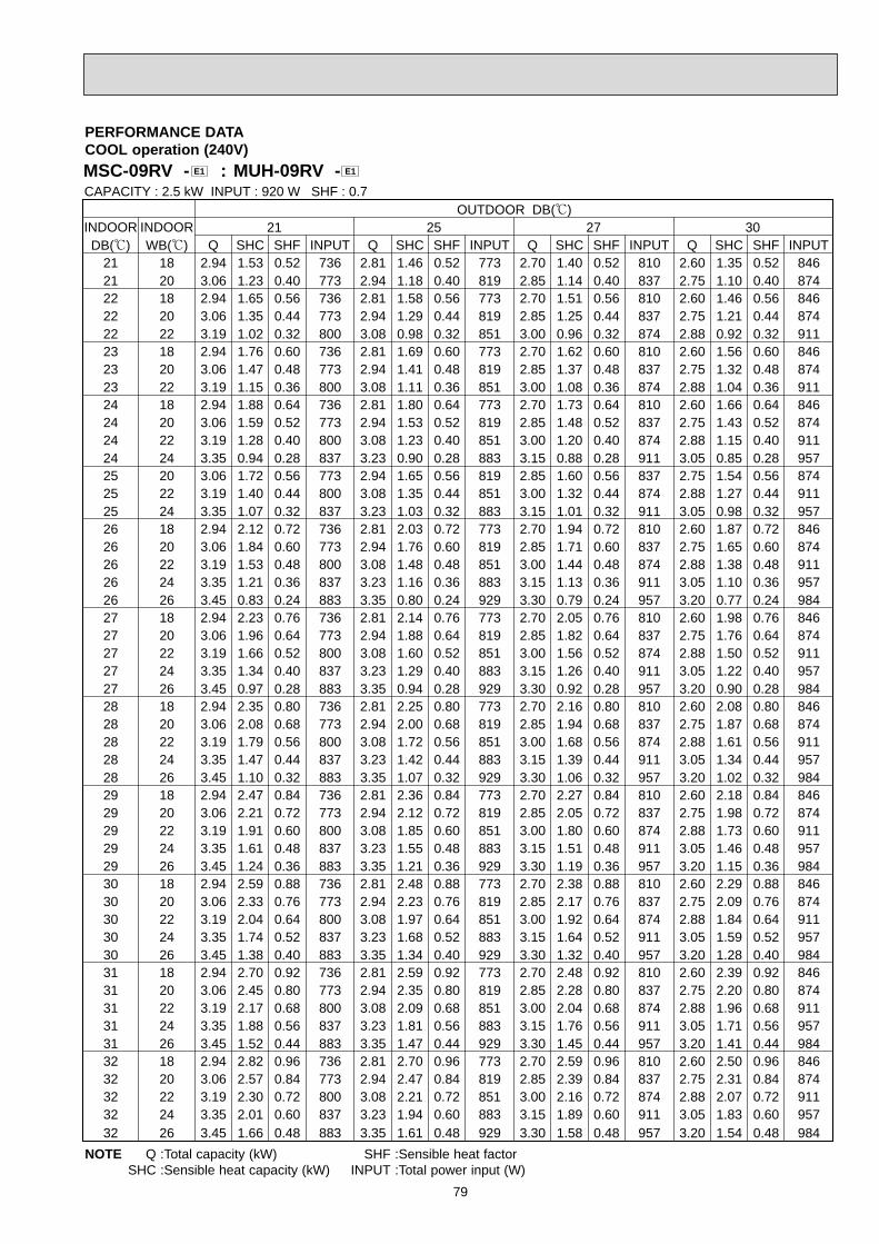
79
MSC-09RV - : MUH-09RV - E1E1
PERFORMANCE DATACOOL operation (240V)
OUTDOOR DB(;)INDOOR INDOOR 21 25 27 30DB(;) WB(;) Q SHC SHF INPUT Q SHC SHF INPUT Q SHC SHF INPUT Q SHC SHF INPUT
21 18 2.94 1.53 0.52 736 2.81 1.46 0.52 773 2.70 1.40 0.52 810 2.60 1.35 0.52 84621 20 3.06 1.23 0.40 773 2.94 1.18 0.40 819 2.85 1.14 0.40 837 2.75 1.10 0.40 87422 18 2.94 1.65 0.56 736 2.81 1.58 0.56 773 2.70 1.51 0.56 810 2.60 1.46 0.56 84622 20 3.06 1.35 0.44 773 2.94 1.29 0.44 819 2.85 1.25 0.44 837 2.75 1.21 0.44 87422 22 3.19 1.02 0.32 800 3.08 0.98 0.32 851 3.00 0.96 0.32 874 2.88 0.92 0.32 91123 18 2.94 1.76 0.60 736 2.81 1.69 0.60 773 2.70 1.62 0.60 810 2.60 1.56 0.60 84623 20 3.06 1.47 0.48 773 2.94 1.41 0.48 819 2.85 1.37 0.48 837 2.75 1.32 0.48 87423 22 3.19 1.15 0.36 800 3.08 1.11 0.36 851 3.00 1.08 0.36 874 2.88 1.04 0.36 91124 18 2.94 1.88 0.64 736 2.81 1.80 0.64 773 2.70 1.73 0.64 810 2.60 1.66 0.64 84624 20 3.06 1.59 0.52 773 2.94 1.53 0.52 819 2.85 1.48 0.52 837 2.75 1.43 0.52 87424 22 3.19 1.28 0.40 800 3.08 1.23 0.40 851 3.00 1.20 0.40 874 2.88 1.15 0.40 91124 24 3.35 0.94 0.28 837 3.23 0.90 0.28 883 3.15 0.88 0.28 911 3.05 0.85 0.28 95725 20 3.06 1.72 0.56 773 2.94 1.65 0.56 819 2.85 1.60 0.56 837 2.75 1.54 0.56 87425 22 3.19 1.40 0.44 800 3.08 1.35 0.44 851 3.00 1.32 0.44 874 2.88 1.27 0.44 91125 24 3.35 1.07 0.32 837 3.23 1.03 0.32 883 3.15 1.01 0.32 911 3.05 0.98 0.32 95726 18 2.94 2.12 0.72 736 2.81 2.03 0.72 773 2.70 1.94 0.72 810 2.60 1.87 0.72 84626 20 3.06 1.84 0.60 773 2.94 1.76 0.60 819 2.85 1.71 0.60 837 2.75 1.65 0.60 87426 22 3.19 1.53 0.48 800 3.08 1.48 0.48 851 3.00 1.44 0.48 874 2.88 1.38 0.48 91126 24 3.35 1.21 0.36 837 3.23 1.16 0.36 883 3.15 1.13 0.36 911 3.05 1.10 0.36 95726 26 3.45 0.83 0.24 883 3.35 0.80 0.24 929 3.30 0.79 0.24 957 3.20 0.77 0.24 98427 18 2.94 2.23 0.76 736 2.81 2.14 0.76 773 2.70 2.05 0.76 810 2.60 1.98 0.76 84627 20 3.06 1.96 0.64 773 2.94 1.88 0.64 819 2.85 1.82 0.64 837 2.75 1.76 0.64 87427 22 3.19 1.66 0.52 800 3.08 1.60 0.52 851 3.00 1.56 0.52 874 2.88 1.50 0.52 91127 24 3.35 1.34 0.40 837 3.23 1.29 0.40 883 3.15 1.26 0.40 911 3.05 1.22 0.40 95727 26 3.45 0.97 0.28 883 3.35 0.94 0.28 929 3.30 0.92 0.28 957 3.20 0.90 0.28 98428 18 2.94 2.35 0.80 736 2.81 2.25 0.80 773 2.70 2.16 0.80 810 2.60 2.08 0.80 84628 20 3.06 2.08 0.68 773 2.94 2.00 0.68 819 2.85 1.94 0.68 837 2.75 1.87 0.68 87428 22 3.19 1.79 0.56 800 3.08 1.72 0.56 851 3.00 1.68 0.56 874 2.88 1.61 0.56 91128 24 3.35 1.47 0.44 837 3.23 1.42 0.44 883 3.15 1.39 0.44 911 3.05 1.34 0.44 95728 26 3.45 1.10 0.32 883 3.35 1.07 0.32 929 3.30 1.06 0.32 957 3.20 1.02 0.32 98429 18 2.94 2.47 0.84 736 2.81 2.36 0.84 773 2.70 2.27 0.84 810 2.60 2.18 0.84 84629 20 3.06 2.21 0.72 773 2.94 2.12 0.72 819 2.85 2.05 0.72 837 2.75 1.98 0.72 87429 22 3.19 1.91 0.60 800 3.08 1.85 0.60 851 3.00 1.80 0.60 874 2.88 1.73 0.60 91129 24 3.35 1.61 0.48 837 3.23 1.55 0.48 883 3.15 1.51 0.48 911 3.05 1.46 0.48 95729 26 3.45 1.24 0.36 883 3.35 1.21 0.36 929 3.30 1.19 0.36 957 3.20 1.15 0.36 98430 18 2.94 2.59 0.88 736 2.81 2.48 0.88 773 2.70 2.38 0.88 810 2.60 2.29 0.88 84630 20 3.06 2.33 0.76 773 2.94 2.23 0.76 819 2.85 2.17 0.76 837 2.75 2.09 0.76 87430 22 3.19 2.04 0.64 800 3.08 1.97 0.64 851 3.00 1.92 0.64 874 2.88 1.84 0.64 91130 24 3.35 1.74 0.52 837 3.23 1.68 0.52 883 3.15 1.64 0.52 911 3.05 1.59 0.52 95730 26 3.45 1.38 0.40 883 3.35 1.34 0.40 929 3.30 1.32 0.40 957 3.20 1.28 0.40 98431 18 2.94 2.70 0.92 736 2.81 2.59 0.92 773 2.70 2.48 0.92 810 2.60 2.39 0.92 84631 20 3.06 2.45 0.80 773 2.94 2.35 0.80 819 2.85 2.28 0.80 837 2.75 2.20 0.80 87431 22 3.19 2.17 0.68 800 3.08 2.09 0.68 851 3.00 2.04 0.68 874 2.88 1.96 0.68 91131 24 3.35 1.88 0.56 837 3.23 1.81 0.56 883 3.15 1.76 0.56 911 3.05 1.71 0.56 95731 26 3.45 1.52 0.44 883 3.35 1.47 0.44 929 3.30 1.45 0.44 957 3.20 1.41 0.44 98432 18 2.94 2.82 0.96 736 2.81 2.70 0.96 773 2.70 2.59 0.96 810 2.60 2.50 0.96 84632 20 3.06 2.57 0.84 773 2.94 2.47 0.84 819 2.85 2.39 0.84 837 2.75 2.31 0.84 87432 22 3.19 2.30 0.72 800 3.08 2.21 0.72 851 3.00 2.16 0.72 874 2.88 2.07 0.72 91132 24 3.35 2.01 0.60 837 3.23 1.94 0.60 883 3.15 1.89 0.60 911 3.05 1.83 0.60 95732 26 3.45 1.66 0.48 883 3.35 1.61 0.48 929 3.30 1.58 0.48 957 3.20 1.54 0.48 984
CAPACITY : 2.5 kW INPUT : 920 W SHF : 0.7
NOTE Q :Total capacity (kW) SHF :Sensible heat factorSHC :Sensible heat capacity (kW) INPUT :Total power input (W)

80
MSC-09RV - : MUH-09RV - E1E1
PERFORMANCE DATACOOL operation (240V)
OUTDOOR DB(;)INDOOR INDOOR 35 40 43DB(;) WB(;) Q SHC SHF INPUT Q SHC SHF INPUT
21 18 2.45 1.27 0.52 902 2.25 1.17 0.52 95721 20 2.58 1.03 0.40 938 2.40 0.96 0.40 98422 18 2.45 1.37 0.56 902 2.25 1.26 0.56 95722 20 2.58 1.13 0.44 938 2.40 1.06 0.44 98422 22 2.73 0.87 0.32 975 2.55 0.82 0.32 103023 18 2.45 1.47 0.60 902 2.25 1.35 0.60 95723 20 2.58 1.24 0.48 938 2.40 1.15 0.48 98423 22 2.73 0.98 0.36 975 2.55 0.92 0.36 103024 18 2.45 1.57 0.64 902 2.25 1.44 0.64 95724 20 2.58 1.34 0.52 938 2.40 1.25 0.52 98424 22 2.73 1.09 0.40 975 2.55 1.02 0.40 103024 24 2.88 0.81 0.28 1012 2.70 0.76 0.28 105825 20 2.58 1.44 0.56 938 2.40 1.34 0.56 98425 22 2.73 1.20 0.44 975 2.55 1.12 0.44 103025 24 2.88 0.92 0.32 1012 2.70 0.86 0.32 105826 18 2.45 1.76 0.72 902 2.25 1.62 0.72 95726 20 2.58 1.55 0.60 938 2.40 1.44 0.60 98426 22 2.73 1.31 0.48 975 2.55 1.22 0.48 103026 24 2.88 1.04 0.36 1012 2.70 0.97 0.36 105826 26 3.03 0.73 0.24 1049 2.85 0.68 0.24 109527 18 2.45 1.86 0.76 902 2.25 1.71 0.76 95727 20 2.58 1.65 0.64 938 2.40 1.54 0.64 98427 22 2.73 1.42 0.52 975 2.55 1.33 0.52 103027 24 2.88 1.15 0.40 1012 2.70 1.08 0.40 105827 26 3.03 0.85 0.28 1049 2.85 0.80 0.28 109528 18 2.45 1.96 0.80 902 2.25 1.80 0.80 95728 20 2.58 1.75 0.68 938 2.40 1.63 0.68 98428 22 2.73 1.53 0.56 975 2.55 1.43 0.56 103028 24 2.88 1.27 0.44 1012 2.70 1.19 0.44 105828 26 3.03 0.97 0.32 1049 2.85 0.91 0.32 109529 18 2.45 2.06 0.84 902 2.25 1.89 0.84 95729 20 2.58 1.85 0.72 938 2.40 1.73 0.72 98429 22 2.73 1.64 0.60 975 2.55 1.53 0.60 103029 24 2.88 1.38 0.48 1012 2.70 1.30 0.48 105829 26 3.03 1.09 0.36 1049 2.85 1.03 0.36 109530 18 2.45 2.16 0.88 902 2.25 1.98 0.88 95730 20 2.58 1.96 0.76 938 2.40 1.82 0.76 98430 22 2.73 1.74 0.64 975 2.55 1.63 0.64 103030 24 2.88 1.50 0.52 1012 2.70 1.40 0.52 105830 26 3.03 1.21 0.40 1049 2.85 1.14 0.40 109531 18 2.45 2.25 0.92 902 2.25 2.07 0.92 95731 20 2.58 2.06 0.80 938 2.40 1.92 0.80 98431 22 2.73 1.85 0.68 975 2.55 1.73 0.68 103031 24 2.88 1.61 0.56 1012 2.70 1.51 0.56 105831 26 3.03 1.33 0.44 1049 2.85 1.25 0.44 109532 18 2.45 2.35 0.96 902 2.25 2.16 0.96 95732 20 2.58 2.16 0.84 938 2.40 2.02 0.84 98432 22 2.73 1.96 0.72 975 2.55 1.84 0.72 103032 24 2.88 1.73 0.60 1012 2.70 1.62 0.60 105832 26 3.03 1.45 0.48 1049 2.85 1.37 0.48 1095
CAPACITY : 2.5 kW INPUT : 920 W SHF : 0.7
Q SHC SHF INPUT2.16 1.12 0.52 9752.31 0.93 0.40 10122.16 1.21 0.56 9752.31 1.02 0.44 10122.46 0.79 0.32 10492.16 1.30 0.60 9752.31 1.11 0.48 10122.46 0.89 0.36 10492.16 1.38 0.64 9752.31 1.20 0.52 10122.46 0.99 0.40 10492.63 0.74 0.28 10812.31 1.30 0.56 10122.46 1.08 0.44 10492.63 0.84 0.32 10812.16 1.56 0.72 9752.31 1.39 0.60 10122.46 1.18 0.48 10492.63 0.95 0.36 10812.76 0.66 0.24 11182.16 1.64 0.76 9752.31 1.48 0.64 10122.46 1.28 0.52 10492.63 1.05 0.40 10812.76 0.77 0.28 11182.16 1.73 0.80 9752.31 1.57 0.68 10122.46 1.38 0.56 10492.63 1.16 0.44 10812.76 0.88 0.32 11182.16 1.82 0.84 9752.31 1.67 0.72 10122.46 1.48 0.60 10492.63 1.26 0.48 10812.76 0.99 0.36 11182.16 1.90 0.88 9752.31 1.76 0.76 10122.46 1.58 0.64 10492.63 1.37 0.52 10812.76 1.11 0.40 11182.16 1.99 0.92 9752.31 1.85 0.80 10122.46 1.67 0.68 10492.63 1.47 0.56 10812.76 1.22 0.44 11182.16 2.08 0.96 9752.31 1.94 0.84 10122.46 1.77 0.72 10492.63 1.58 0.60 10812.76 1.33 0.48 1118
NOTE Q :Total capacity (kW) SHF :Sensible heat factorSHC :Sensible heat capacity (kW) INPUT :Total power input (W)

81
MSC-12RV - : MUH-12RV - E1E1
PERFORMANCE DATACOOL operation (220V)
OUTDOOR DB(;)INDOOR INDOOR 21 25 27 30DB(;) WB(;) Q SHC SHF INPUT Q SHC SHF INPUT Q SHC SHF INPUT Q SHC SHF INPUT
21 18 4.00 1.96 0.49 976 3.83 1.87 0.49 1025 3.67 1.80 0.49 1074 3.54 1.73 0.49 112221 20 4.17 1.54 0.37 1025 4.00 1.48 0.37 1086 3.88 1.43 0.37 1110 3.74 1.38 0.37 115922 18 4.00 2.12 0.53 976 3.83 2.03 0.53 1025 3.67 1.95 0.53 1074 3.54 1.87 0.53 112222 20 4.17 1.71 0.41 1025 4.00 1.64 0.41 1086 3.88 1.59 0.41 1110 3.74 1.53 0.41 115922 22 4.34 1.26 0.29 1061 4.18 1.21 0.29 1129 4.08 1.18 0.29 1159 3.91 1.13 0.29 120823 18 4.00 2.28 0.57 976 3.83 2.18 0.57 1025 3.67 2.09 0.57 1074 3.54 2.02 0.57 112223 20 4.17 1.87 0.45 1025 4.00 1.80 0.45 1086 3.88 1.74 0.45 1110 3.74 1.68 0.45 115923 22 4.34 1.43 0.33 1061 4.18 1.38 0.33 1129 4.08 1.35 0.33 1159 3.91 1.29 0.33 120824 18 4.00 2.44 0.61 976 3.83 2.33 0.61 1025 3.67 2.24 0.61 1074 3.54 2.16 0.61 112224 20 4.17 2.04 0.49 1025 4.00 1.96 0.49 1086 3.88 1.90 0.49 1110 3.74 1.83 0.49 115924 22 4.34 1.60 0.37 1061 4.18 1.55 0.37 1129 4.08 1.51 0.37 1159 3.91 1.45 0.37 120824 24 4.56 1.14 0.25 1110 4.39 1.10 0.25 1171 4.28 1.07 0.25 1208 4.15 1.04 0.25 126925 20 4.17 2.21 0.53 1025 4.00 2.12 0.53 1086 3.88 2.05 0.53 1110 3.74 1.98 0.53 115925 22 4.34 1.78 0.41 1061 4.18 1.71 0.41 1129 4.08 1.67 0.41 1159 3.91 1.60 0.41 120825 24 4.56 1.32 0.29 1110 4.39 1.27 0.29 1171 4.28 1.24 0.29 1208 4.15 1.20 0.29 126926 18 4.00 2.76 0.69 976 3.83 2.64 0.69 1025 3.67 2.53 0.69 1074 3.54 2.44 0.69 112226 20 4.17 2.37 0.57 1025 4.00 2.28 0.57 1086 3.88 2.21 0.57 1110 3.74 2.13 0.57 115926 22 4.34 1.95 0.45 1061 4.18 1.88 0.45 1129 4.08 1.84 0.45 1159 3.91 1.76 0.45 120826 24 4.56 1.50 0.33 1110 4.39 1.45 0.33 1171 4.28 1.41 0.33 1208 4.15 1.37 0.33 126926 26 4.69 0.99 0.21 1171 4.56 0.96 0.21 1232 4.49 0.94 0.21 1269 4.35 0.91 0.21 130527 18 4.00 2.92 0.73 976 3.83 2.79 0.73 1025 3.67 2.68 0.73 1074 3.54 2.58 0.73 112227 20 4.17 2.54 0.61 1025 4.00 2.44 0.61 1086 3.88 2.36 0.61 1110 3.74 2.28 0.61 115927 22 4.34 2.12 0.49 1061 4.18 2.05 0.49 1129 4.08 2.00 0.49 1159 3.91 1.92 0.49 120827 24 4.56 1.69 0.37 1110 4.39 1.62 0.37 1171 4.28 1.59 0.37 1208 4.15 1.53 0.37 126927 26 4.69 1.17 0.25 1171 4.56 1.14 0.25 1232 4.49 1.12 0.25 1269 4.35 1.09 0.25 130528 18 4.00 3.08 0.77 976 3.83 2.95 0.77 1025 3.67 2.83 0.77 1074 3.54 2.72 0.77 112228 20 4.17 2.71 0.65 1025 4.00 2.60 0.65 1086 3.88 2.52 0.65 1110 3.74 2.43 0.65 115928 22 4.34 2.30 0.53 1061 4.18 2.22 0.53 1129 4.08 2.16 0.53 1159 3.91 2.07 0.53 120828 24 4.56 1.87 0.41 1110 4.39 1.80 0.41 1171 4.28 1.76 0.41 1208 4.15 1.70 0.41 126928 26 4.69 1.36 0.29 1171 4.56 1.32 0.29 1232 4.49 1.30 0.29 1269 4.35 1.26 0.29 130529 18 4.00 3.24 0.81 976 3.83 3.10 0.81 1025 3.67 2.97 0.81 1074 3.54 2.86 0.81 112229 20 4.17 2.87 0.69 1025 4.00 2.76 0.69 1086 3.88 2.67 0.69 1110 3.74 2.58 0.69 115929 22 4.34 2.47 0.57 1061 4.18 2.38 0.57 1129 4.08 2.33 0.57 1159 3.91 2.23 0.57 120829 24 4.56 2.05 0.45 1110 4.39 1.97 0.45 1171 4.28 1.93 0.45 1208 4.15 1.87 0.45 126929 26 4.69 1.55 0.33 1171 4.56 1.50 0.33 1232 4.49 1.48 0.33 1269 4.35 1.44 0.33 130530 18 4.00 3.40 0.85 976 3.83 3.25 0.85 1025 3.67 3.12 0.85 1074 3.54 3.01 0.85 112230 20 4.17 3.04 0.73 1025 4.00 2.92 0.73 1086 3.88 2.83 0.73 1110 3.74 2.73 0.73 115930 22 4.34 2.64 0.61 1061 4.18 2.55 0.61 1129 4.08 2.49 0.61 1159 3.91 2.39 0.61 120830 24 4.56 2.23 0.49 1110 4.39 2.15 0.49 1171 4.28 2.10 0.49 1208 4.15 2.03 0.49 126930 26 4.69 1.74 0.37 1171 4.56 1.69 0.37 1232 4.49 1.66 0.37 1269 4.35 1.61 0.37 130531 18 4.00 3.56 0.89 976 3.83 3.40 0.89 1025 3.67 3.27 0.89 1074 3.54 3.15 0.89 112231 20 4.17 3.21 0.77 1025 4.00 3.08 0.77 1086 3.88 2.98 0.77 1110 3.74 2.88 0.77 115931 22 4.34 2.82 0.65 1061 4.18 2.72 0.65 1129 4.08 2.65 0.65 1159 3.91 2.54 0.65 120831 24 4.56 2.41 0.53 1110 4.39 2.32 0.53 1171 4.28 2.27 0.53 1208 4.15 2.20 0.53 126931 26 4.69 1.92 0.41 1171 4.56 1.87 0.41 1232 4.49 1.84 0.41 1269 4.35 1.78 0.41 130532 18 4.00 3.72 0.93 976 3.83 3.56 0.93 1025 3.67 3.41 0.93 1074 3.54 3.29 0.93 112232 20 4.17 3.37 0.81 1025 4.00 3.24 0.81 1086 3.88 3.14 0.81 1110 3.74 3.03 0.81 115932 22 4.34 2.99 0.69 1061 4.18 2.89 0.69 1129 4.08 2.82 0.69 1159 3.91 2.70 0.69 120832 24 4.56 2.60 0.57 1110 4.39 2.50 0.57 1171 4.28 2.44 0.57 1208 4.15 2.36 0.57 126932 26 4.69 2.11 0.45 1171 4.56 2.05 0.45 1232 4.49 2.02 0.45 1269 4.35 1.96 0.45 1305
CAPACITY : 3.4 kW INPUT : 1220 W SHF : 0.67
NOTE Q :Total capacity (kW) SHF :Sensible heat factorSHC :Sensible heat capacity (kW) INPUT :Total power input (W)

82
MSC-12RV - : MUH-12RV - E1E1
PERFORMANCE DATACOOL operation (220V)
OUTDOOR DB(;)INDOOR INDOOR 35 40 43DB(;) WB(;) Q SHC SHF INPUT Q SHC SHF INPUT
21 18 3.33 1.63 0.49 1196 3.06 1.50 0.49 126921 20 3.50 1.30 0.37 1244 3.26 1.21 0.37 130522 18 3.33 1.77 0.53 1196 3.06 1.62 0.53 126922 20 3.50 1.44 0.41 1244 3.26 1.34 0.41 130522 22 3.71 1.07 0.29 1293 3.47 1.01 0.29 136623 18 3.33 1.90 0.57 1196 3.06 1.74 0.57 126923 20 3.50 1.58 0.45 1244 3.26 1.47 0.45 130523 22 3.71 1.22 0.33 1293 3.47 1.14 0.33 136624 18 3.33 2.03 0.61 1196 3.06 1.87 0.61 126924 20 3.50 1.72 0.49 1244 3.26 1.60 0.49 130524 22 3.71 1.37 0.37 1293 3.47 1.28 0.37 136624 24 3.91 0.98 0.25 1342 3.67 0.92 0.25 140325 20 3.50 1.86 0.53 1244 3.26 1.73 0.53 130525 22 3.71 1.52 0.41 1293 3.47 1.42 0.41 136625 24 3.91 1.13 0.29 1342 3.67 1.06 0.29 140326 18 3.33 2.30 0.69 1196 3.06 2.11 0.69 126926 20 3.50 2.00 0.57 1244 3.26 1.86 0.57 130526 22 3.71 1.67 0.45 1293 3.47 1.56 0.45 136626 24 3.91 1.29 0.33 1342 3.67 1.21 0.33 140326 26 4.11 0.86 0.21 1391 3.88 0.81 0.21 145227 18 3.33 2.43 0.73 1196 3.06 2.23 0.73 126927 20 3.50 2.14 0.61 1244 3.26 1.99 0.61 130527 22 3.71 1.82 0.49 1293 3.47 1.70 0.49 136627 24 3.91 1.45 0.37 1342 3.67 1.36 0.37 140327 26 4.11 1.03 0.25 1391 3.88 0.97 0.25 145228 18 3.33 2.57 0.77 1196 3.06 2.36 0.77 126928 20 3.50 2.28 0.65 1244 3.26 2.12 0.65 130528 22 3.71 1.96 0.53 1293 3.47 1.84 0.53 136628 24 3.91 1.60 0.41 1342 3.67 1.51 0.41 140328 26 4.11 1.19 0.29 1391 3.88 1.12 0.29 145229 18 3.33 2.70 0.81 1196 3.06 2.48 0.81 126929 20 3.50 2.42 0.69 1244 3.26 2.25 0.69 130529 22 3.71 2.11 0.57 1293 3.47 1.98 0.57 136629 24 3.91 1.76 0.45 1342 3.67 1.65 0.45 140329 26 4.11 1.36 0.33 1391 3.88 1.28 0.33 145230 18 3.33 2.83 0.85 1196 3.06 2.60 0.85 126930 20 3.50 2.56 0.73 1244 3.26 2.38 0.73 130530 22 3.71 2.26 0.61 1293 3.47 2.12 0.61 136630 24 3.91 1.92 0.49 1342 3.67 1.80 0.49 140330 26 4.11 1.52 0.37 1391 3.88 1.43 0.37 145231 18 3.33 2.97 0.89 1196 3.06 2.72 0.89 126931 20 3.50 2.70 0.77 1244 3.26 2.51 0.77 130531 22 3.71 2.41 0.65 1293 3.47 2.25 0.65 136631 24 3.91 2.07 0.53 1342 3.67 1.95 0.53 140331 26 4.11 1.69 0.41 1391 3.88 1.59 0.41 145232 18 3.33 3.10 0.93 1196 3.06 2.85 0.93 126932 20 3.50 2.84 0.81 1244 3.26 2.64 0.81 130532 22 3.71 2.56 0.69 1293 3.47 2.39 0.69 136632 24 3.91 2.23 0.57 1342 3.67 2.09 0.57 140332 26 4.11 1.85 0.45 1391 3.88 1.74 0.45 1452
CAPACITY : 3.4 kW INPUT : 1220 W SHF : 0.67
Q SHC SHF INPUT2.94 1.44 0.49 12933.15 1.16 0.37 13422.94 1.56 0.53 12933.15 1.29 0.41 13423.35 0.97 0.29 13912.94 1.68 0.57 12933.15 1.42 0.45 13423.35 1.11 0.33 13912.94 1.79 0.61 12933.15 1.54 0.49 13423.35 1.24 0.37 13913.57 0.89 0.25 14343.15 1.67 0.53 13423.35 1.37 0.41 13913.57 1.04 0.29 14342.94 2.03 0.69 12933.15 1.79 0.57 13423.35 1.51 0.45 13913.57 1.18 0.33 14343.76 0.79 0.21 14822.94 2.15 0.73 12933.15 1.92 0.61 13423.35 1.64 0.49 13913.57 1.32 0.37 14343.76 0.94 0.25 14822.94 2.26 0.77 12933.15 2.04 0.65 13423.35 1.77 0.53 13913.57 1.46 0.41 14343.76 1.09 0.29 14822.94 2.38 0.81 12933.15 2.17 0.69 13423.35 1.91 0.57 13913.57 1.61 0.45 14343.76 1.24 0.33 14822.94 2.50 0.85 12933.15 2.30 0.73 13423.35 2.04 0.61 13913.57 1.75 0.49 14343.76 1.39 0.37 14822.94 2.62 0.89 12933.15 2.42 0.77 13423.35 2.18 0.65 13913.57 1.89 0.53 14343.76 1.54 0.41 14822.94 2.74 0.93 12933.15 2.55 0.81 13423.35 2.31 0.69 13913.57 2.03 0.57 14343.76 1.69 0.45 1482
NOTE Q :Total capacity (kW) SHF :Sensible heat factorSHC :Sensible heat capacity (kW) INPUT :Total power input (W)

83
MSC-12RV - : MUH-12RV - E1E1
PERFORMANCE DATACOOL operation (240V)
OUTDOOR DB(;)INDOOR INDOOR 21 25 27 30DB(;) WB(;) Q SHC SHF INPUT Q SHC SHF INPUT Q SHC SHF INPUT Q SHC SHF INPUT
21 18 4.00 1.96 0.49 1040 3.83 1.87 0.49 1092 3.67 1.80 0.49 1144 3.54 1.73 0.49 119621 20 4.17 1.54 0.37 1092 4.00 1.48 0.37 1157 3.88 1.43 0.37 1183 3.74 1.38 0.37 123522 18 4.00 2.12 0.53 1040 3.83 2.03 0.53 1092 3.67 1.95 0.53 1144 3.54 1.87 0.53 119622 20 4.17 1.71 0.41 1092 4.00 1.64 0.41 1157 3.88 1.59 0.41 1183 3.74 1.53 0.41 123522 22 4.34 1.26 0.29 1131 4.18 1.21 0.29 1203 4.08 1.18 0.29 1235 3.91 1.13 0.29 128723 18 4.00 2.28 0.57 1040 3.83 2.18 0.57 1092 3.67 2.09 0.57 1144 3.54 2.02 0.57 119623 20 4.17 1.87 0.45 1092 4.00 1.80 0.45 1157 3.88 1.74 0.45 1183 3.74 1.68 0.45 123523 22 4.34 1.43 0.33 1131 4.18 1.38 0.33 1203 4.08 1.35 0.33 1235 3.91 1.29 0.33 128724 18 4.00 2.44 0.61 1040 3.83 2.33 0.61 1092 3.67 2.24 0.61 1144 3.54 2.16 0.61 119624 20 4.17 2.04 0.49 1092 4.00 1.96 0.49 1157 3.88 1.90 0.49 1183 3.74 1.83 0.49 123524 22 4.34 1.60 0.37 1131 4.18 1.55 0.37 1203 4.08 1.51 0.37 1235 3.91 1.45 0.37 128724 24 4.56 1.14 0.25 1183 4.39 1.10 0.25 1248 4.28 1.07 0.25 1287 4.15 1.04 0.25 135225 20 4.17 2.21 0.53 1092 4.00 2.12 0.53 1157 3.88 2.05 0.53 1183 3.74 1.98 0.53 123525 22 4.34 1.78 0.41 1131 4.18 1.71 0.41 1203 4.08 1.67 0.41 1235 3.91 1.60 0.41 128725 24 4.56 1.32 0.29 1183 4.39 1.27 0.29 1248 4.28 1.24 0.29 1287 4.15 1.20 0.29 135226 18 4.00 2.76 0.69 1040 3.83 2.64 0.69 1092 3.67 2.53 0.69 1144 3.54 2.44 0.69 119626 20 4.17 2.37 0.57 1092 4.00 2.28 0.57 1157 3.88 2.21 0.57 1183 3.74 2.13 0.57 123526 22 4.34 1.95 0.45 1131 4.18 1.88 0.45 1203 4.08 1.84 0.45 1235 3.91 1.76 0.45 128726 24 4.56 1.50 0.33 1183 4.39 1.45 0.33 1248 4.28 1.41 0.33 1287 4.15 1.37 0.33 135226 26 4.69 0.99 0.21 1248 4.56 0.96 0.21 1313 4.49 0.94 0.21 1352 4.35 0.91 0.21 139127 18 4.00 2.92 0.73 1040 3.83 2.79 0.73 1092 3.67 2.68 0.73 1144 3.54 2.58 0.73 119627 20 4.17 2.54 0.61 1092 4.00 2.44 0.61 1157 3.88 2.36 0.61 1183 3.74 2.28 0.61 123527 22 4.34 2.12 0.49 1131 4.18 2.05 0.49 1203 4.08 2.00 0.49 1235 3.91 1.92 0.49 128727 24 4.56 1.69 0.37 1183 4.39 1.62 0.37 1248 4.28 1.59 0.37 1287 4.15 1.53 0.37 135227 26 4.69 1.17 0.25 1248 4.56 1.14 0.25 1313 4.49 1.12 0.25 1352 4.35 1.09 0.25 139128 18 4.00 3.08 0.77 1040 3.83 2.95 0.77 1092 3.67 2.83 0.77 1144 3.54 2.72 0.77 119628 20 4.17 2.71 0.65 1092 4.00 2.60 0.65 1157 3.88 2.52 0.65 1183 3.74 2.43 0.65 123528 22 4.34 2.30 0.53 1131 4.18 2.22 0.53 1203 4.08 2.16 0.53 1235 3.91 2.07 0.53 128728 24 4.56 1.87 0.41 1183 4.39 1.80 0.41 1248 4.28 1.76 0.41 1287 4.15 1.70 0.41 135228 26 4.69 1.36 0.29 1248 4.56 1.32 0.29 1313 4.49 1.30 0.29 1352 4.35 1.26 0.29 139129 18 4.00 3.24 0.81 1040 3.83 3.10 0.81 1092 3.67 2.97 0.81 1144 3.54 2.86 0.81 119629 20 4.17 2.87 0.69 1092 4.00 2.76 0.69 1157 3.88 2.67 0.69 1183 3.74 2.58 0.69 123529 22 4.34 2.47 0.57 1131 4.18 2.38 0.57 1203 4.08 2.33 0.57 1235 3.91 2.23 0.57 128729 24 4.56 2.05 0.45 1183 4.39 1.97 0.45 1248 4.28 1.93 0.45 1287 4.15 1.87 0.45 135229 26 4.69 1.55 0.33 1248 4.56 1.50 0.33 1313 4.49 1.48 0.33 1352 4.35 1.44 0.33 139130 18 4.00 3.40 0.85 1040 3.83 3.25 0.85 1092 3.67 3.12 0.85 1144 3.54 3.01 0.85 119630 20 4.17 3.04 0.73 1092 4.00 2.92 0.73 1157 3.88 2.83 0.73 1183 3.74 2.73 0.73 123530 22 4.34 2.64 0.61 1131 4.18 2.55 0.61 1203 4.08 2.49 0.61 1235 3.91 2.39 0.61 128730 24 4.56 2.23 0.49 1183 4.39 2.15 0.49 1248 4.28 2.10 0.49 1287 4.15 2.03 0.49 135230 26 4.69 1.74 0.37 1248 4.56 1.69 0.37 1313 4.49 1.66 0.37 1352 4.35 1.61 0.37 139131 18 4.00 3.56 0.89 1040 3.83 3.40 0.89 1092 3.67 3.27 0.89 1144 3.54 3.15 0.89 119631 20 4.17 3.21 0.77 1092 4.00 3.08 0.77 1157 3.88 2.98 0.77 1183 3.74 2.88 0.77 123531 22 4.34 2.82 0.65 1131 4.18 2.72 0.65 1203 4.08 2.65 0.65 1235 3.91 2.54 0.65 128731 24 4.56 2.41 0.53 1183 4.39 2.32 0.53 1248 4.28 2.27 0.53 1287 4.15 2.20 0.53 135231 26 4.69 1.92 0.41 1248 4.56 1.87 0.41 1313 4.49 1.84 0.41 1352 4.35 1.78 0.41 139132 18 4.00 3.72 0.93 1040 3.83 3.56 0.93 1092 3.67 3.41 0.93 1144 3.54 3.29 0.93 119632 20 4.17 3.37 0.81 1092 4.00 3.24 0.81 1157 3.88 3.14 0.81 1183 3.74 3.03 0.81 123532 22 4.34 2.99 0.69 1131 4.18 2.89 0.69 1203 4.08 2.82 0.69 1235 3.91 2.70 0.69 128732 24 4.56 2.60 0.57 1183 4.39 2.50 0.57 1248 4.28 2.44 0.57 1287 4.15 2.36 0.57 135232 26 4.69 2.11 0.45 1248 4.56 2.05 0.45 1313 4.49 2.02 0.45 1352 4.35 1.96 0.45 1391
CAPACITY : 3.4 kW INPUT : 1300 W SHF : 0.67
NOTE Q :Total capacity (kW) SHF :Sensible heat factorSHC :Sensible heat capacity (kW) INPUT :Total power input (W)

84
MSC-12RV - : MUH-12RV - E1E1
PERFORMANCE DATACOOL operation (240V)
OUTDOOR DB(;)INDOOR INDOOR 35 40 43DB(;) WB(;) Q SHC SHF INPUT Q SHC SHF INPUT
21 18 3.33 1.63 0.49 1274 3.06 1.50 0.49 135221 20 3.50 1.30 0.37 1326 3.26 1.21 0.37 139122 18 3.33 1.77 0.53 1274 3.06 1.62 0.53 135222 20 3.50 1.44 0.41 1326 3.26 1.34 0.41 139122 22 3.71 1.07 0.29 1378 3.47 1.01 0.29 145623 18 3.33 1.90 0.57 1274 3.06 1.74 0.57 135223 20 3.50 1.58 0.45 1326 3.26 1.47 0.45 139123 22 3.71 1.22 0.33 1378 3.47 1.14 0.33 145624 18 3.33 2.03 0.61 1274 3.06 1.87 0.61 135224 20 3.50 1.72 0.49 1326 3.26 1.60 0.49 139124 22 3.71 1.37 0.37 1378 3.47 1.28 0.37 145624 24 3.91 0.98 0.25 1430 3.67 0.92 0.25 149525 20 3.50 1.86 0.53 1326 3.26 1.73 0.53 139125 22 3.71 1.52 0.41 1378 3.47 1.42 0.41 145625 24 3.91 1.13 0.29 1430 3.67 1.06 0.29 149526 18 3.33 2.30 0.69 1274 3.06 2.11 0.69 135226 20 3.50 2.00 0.57 1326 3.26 1.86 0.57 139126 22 3.71 1.67 0.45 1378 3.47 1.56 0.45 145626 24 3.91 1.29 0.33 1430 3.67 1.21 0.33 149526 26 4.11 0.86 0.21 1482 3.88 0.81 0.21 154727 18 3.33 2.43 0.73 1274 3.06 2.23 0.73 135227 20 3.50 2.14 0.61 1326 3.26 1.99 0.61 139127 22 3.71 1.82 0.49 1378 3.47 1.70 0.49 145627 24 3.91 1.45 0.37 1430 3.67 1.36 0.37 149527 26 4.11 1.03 0.25 1482 3.88 0.97 0.25 154728 18 3.33 2.57 0.77 1274 3.06 2.36 0.77 135228 20 3.50 2.28 0.65 1326 3.26 2.12 0.65 139128 22 3.71 1.96 0.53 1378 3.47 1.84 0.53 145628 24 3.91 1.60 0.41 1430 3.67 1.51 0.41 149528 26 4.11 1.19 0.29 1482 3.88 1.12 0.29 154729 18 3.33 2.70 0.81 1274 3.06 2.48 0.81 135229 20 3.50 2.42 0.69 1326 3.26 2.25 0.69 139129 22 3.71 2.11 0.57 1378 3.47 1.98 0.57 145629 24 3.91 1.76 0.45 1430 3.67 1.65 0.45 149529 26 4.11 1.36 0.33 1482 3.88 1.28 0.33 154730 18 3.33 2.83 0.85 1274 3.06 2.60 0.85 135230 20 3.50 2.56 0.73 1326 3.26 2.38 0.73 139130 22 3.71 2.26 0.61 1378 3.47 2.12 0.61 145630 24 3.91 1.92 0.49 1430 3.67 1.80 0.49 149530 26 4.11 1.52 0.37 1482 3.88 1.43 0.37 154731 18 3.33 2.97 0.89 1274 3.06 2.72 0.89 135231 20 3.50 2.70 0.77 1326 3.26 2.51 0.77 139131 22 3.71 2.41 0.65 1378 3.47 2.25 0.65 145631 24 3.91 2.07 0.53 1430 3.67 1.95 0.53 149531 26 4.11 1.69 0.41 1482 3.88 1.59 0.41 154732 18 3.33 3.10 0.93 1274 3.06 2.85 0.93 135232 20 3.50 2.84 0.81 1326 3.26 2.64 0.81 139132 22 3.71 2.56 0.69 1378 3.47 2.39 0.69 145632 24 3.91 2.23 0.57 1430 3.67 2.09 0.57 149532 26 4.11 1.85 0.45 1482 3.88 1.74 0.45 1547
CAPACITY : 3.4 kW INPUT : 1300 W SHF : 0.67
Q SHC SHF INPUT2.94 1.44 0.49 13783.15 1.16 0.37 14302.94 1.56 0.53 13783.15 1.29 0.41 14303.35 0.97 0.29 14822.94 1.68 0.57 13783.15 1.42 0.45 14303.35 1.11 0.33 14822.94 1.79 0.61 13783.15 1.54 0.49 14303.35 1.24 0.37 14823.57 0.89 0.25 15283.15 1.67 0.53 14303.35 1.37 0.41 14823.57 1.04 0.29 15282.94 2.03 0.69 13783.15 1.79 0.57 14303.35 1.51 0.45 14823.57 1.18 0.33 15283.76 0.79 0.21 15802.94 2.15 0.73 13783.15 1.92 0.61 14303.35 1.64 0.49 14823.57 1.32 0.37 15283.76 0.94 0.25 15802.94 2.26 0.77 13783.15 2.04 0.65 14303.35 1.77 0.53 14823.57 1.46 0.41 15283.76 1.09 0.29 15802.94 2.38 0.81 13783.15 2.17 0.69 14303.35 1.91 0.57 14823.57 1.61 0.45 15283.76 1.24 0.33 15802.94 2.50 0.85 13783.15 2.30 0.73 14303.35 2.04 0.61 14823.57 1.75 0.49 15283.76 1.39 0.37 15802.94 2.62 0.89 13783.15 2.42 0.77 14303.35 2.18 0.65 14823.57 1.89 0.53 15283.76 1.54 0.41 15802.94 2.74 0.93 13783.15 2.55 0.81 14303.35 2.31 0.69 14823.57 2.03 0.57 15283.76 1.69 0.45 1580
NOTE Q :Total capacity (kW) SHF :Sensible heat factorSHC :Sensible heat capacity (kW) INPUT :Total power input (W)

85
MSC-07RV - : MUH-07RV - E1E1
PERFORMANCE DATAHEAT operation (220V)
MSC-09RV - : MUH-09RV - E1E1
OUTDOOR DB(;)INDOOR -10 -5 0 5 10 15 20DB(;) Q INPUT Q INPUT Q INPUT Q INPUT Q INPUT Q INPUT Q INPUT
15 1.58 442 1.90 530 2.23 598 2.55 646 2.88 687 3.18 707 3.50 72121 1.50 476 1.80 564 2.13 626 2.43 673 2.75 707 3.05 728 3.36 75526 1.35 510 1.68 598 1.98 660 2.30 707 2.63 741 2.93 762 3.25 782
CAPACITY : 2.5 kW INPUT : 680 W
OUTDOOR DB(;)INDOOR -10 -5 0 5 10 15 20DB(;) Q INPUT Q INPUT Q INPUT Q INPUT Q INPUT Q INPUT Q INPUT
15 1.95 598 2.36 718 2.76 810 3.16 874 3.57 929 3.94 957 4.34 97521 1.86 644 2.23 764 2.64 846 3.01 911 3.41 957 3.78 984 4.17 102126 1.67 690 2.08 810 2.45 892 2.85 957 3.26 1003 3.63 1030 4.03 1058
CAPACITY : 3.1 kW INPUT : 920 W
MSC-12RV - : MUH-12RV - E1E1
OUTDOOR DB(;)INDOOR -10 -5 0 5 10 15 20DB(;) Q INPUT Q INPUT Q INPUT Q INPUT Q INPUT Q INPUT Q INPUT
15 2.52 819 3.04 983 3.56 1109 4.08 1197 4.60 1273 5.08 1310 5.60 133621 2.40 882 2.88 1046 3.40 1159 3.88 1247 4.40 1310 4.88 1348 5.38 139926 2.16 945 2.68 1109 3.16 1222 3.68 1310 4.20 1373 4.68 1411 5.20 1449
CAPACITY : 4.0 kW INPUT : 1260 W
MSC-07RV - : MUH-07RV - E1E1
HEAT operation (240V)
OUTDOOR DB(;)INDOOR -10 -5 0 5 10 15 20DB(;) Q INPUT Q INPUT Q INPUT Q INPUT Q INPUT Q INPUT Q INPUT
15 1.58 468 1.90 562 2.23 634 2.55 684 2.88 727 3.18 749 3.50 76321 1.50 504 1.80 598 2.13 662 2.43 713 2.75 749 3.05 770 3.36 79926 1.35 540 1.68 634 1.98 698 2.30 749 2.63 785 2.93 806 3.25 828
CAPACITY : 2.5 kW INPUT : 720 W
MSC-09RV - : MUH-09RV - E1E1
OUTDOOR DB(;)INDOOR -10 -5 0 5 10 15 20DB(;) Q INPUT Q INPUT Q INPUT Q INPUT Q INPUT Q INPUT Q INPUT
15 1.95 611 2.36 733 2.76 827 3.16 893 3.57 949 3.94 978 4.34 99621 1.86 658 2.23 780 2.64 865 3.01 931 3.41 978 3.78 1006 4.17 104326 1.67 705 2.08 827 2.45 912 2.85 978 3.26 1025 3.63 1053 4.03 1081
CAPACITY : 3.1 kW INPUT : 940 W
MSC-12RV - : MUH-12RV - E1E1
OUTDOOR DB(;)INDOOR -10 -5 0 5 10 15 20DB(;) Q INPUT Q INPUT Q INPUT Q INPUT Q INPUT Q INPUT Q INPUT
15 2.52 878 3.04 1053 3.56 1188 4.08 1283 4.60 1364 5.08 1404 5.60 143121 2.40 945 2.88 1121 3.40 1242 3.88 1337 4.40 1404 4.88 1445 5.38 149926 2.16 1013 2.68 1188 3.16 1310 3.68 1404 4.20 1472 4.68 1512 5.20 1553
CAPACITY : 4.0 kW INPUT : 1350 W
NOTE Q :Total capacity (kW) INPUT :Total power input (W)

86
MSC-07RV - (Single) : MUX-10RV - E1E1
PERFORMANCE DATACOOL operation (220V)
INDOOR INDOOR 21 25 27 30DB(;) WB(;) Q SHC SHF INPUT Q SHC SHF INPUT Q SHC SHF INPUT Q SHC SHF INPUT
21 18 2.59 1.45 0.56 592 2.48 1.39 0.56 622 2.38 1.33 0.56 651 2.29 1.28 0.56 68121 20 2.70 1.19 0.44 622 2.59 1.14 0.44 659 2.51 1.10 0.44 673 2.42 1.06 0.44 70322 18 2.59 1.55 0.60 592 2.48 1.49 0.60 622 2.38 1.43 0.60 651 2.29 1.37 0.60 68122 20 2.70 1.29 0.48 622 2.59 1.24 0.48 659 2.51 1.20 0.48 673 2.42 1.16 0.48 70322 22 2.81 1.01 0.36 644 2.71 0.97 0.36 685 2.64 0.95 0.36 703 2.53 0.91 0.36 73323 18 2.59 1.65 0.64 592 2.48 1.58 0.64 622 2.38 1.52 0.64 651 2.29 1.46 0.64 68123 20 2.70 1.40 0.52 622 2.59 1.34 0.52 659 2.51 1.30 0.52 673 2.42 1.26 0.52 70323 22 2.81 1.12 0.40 644 2.71 1.08 0.40 685 2.64 1.06 0.40 703 2.53 1.01 0.40 73324 18 2.59 1.76 0.68 592 2.48 1.68 0.68 622 2.38 1.62 0.68 651 2.29 1.56 0.68 68124 20 2.70 1.51 0.56 622 2.59 1.45 0.56 659 2.51 1.40 0.56 673 2.42 1.36 0.56 70324 22 2.81 1.23 0.44 644 2.71 1.19 0.44 685 2.64 1.16 0.44 703 2.53 1.11 0.44 73324 24 2.95 0.94 0.32 673 2.84 0.91 0.32 710 2.77 0.89 0.32 733 2.68 0.86 0.32 77025 20 2.70 1.62 0.60 622 2.59 1.55 0.60 659 2.51 1.50 0.60 673 2.42 1.45 0.60 70325 22 2.81 1.35 0.48 644 2.71 1.30 0.48 685 2.64 1.27 0.48 703 2.53 1.21 0.48 73325 24 2.95 1.06 0.36 673 2.84 1.02 0.36 710 2.77 1.00 0.36 733 2.68 0.97 0.36 77026 18 2.59 1.96 0.76 592 2.48 1.88 0.76 622 2.38 1.81 0.76 651 2.29 1.74 0.76 68126 20 2.70 1.72 0.64 622 2.59 1.65 0.64 659 2.51 1.61 0.64 673 2.42 1.55 0.64 70326 22 2.81 1.46 0.52 644 2.71 1.41 0.52 685 2.64 1.37 0.52 703 2.53 1.32 0.52 73326 24 2.95 1.18 0.40 673 2.84 1.14 0.40 710 2.77 1.11 0.40 733 2.68 1.07 0.40 77026 26 3.04 0.85 0.28 710 2.95 0.83 0.28 747 2.90 0.81 0.28 770 2.82 0.79 0.28 79227 18 2.59 2.07 0.80 592 2.48 1.98 0.80 622 2.38 1.90 0.80 651 2.29 1.83 0.80 68127 20 2.70 1.83 0.68 622 2.59 1.76 0.68 659 2.51 1.71 0.68 673 2.42 1.65 0.68 70327 22 2.81 1.57 0.56 644 2.71 1.52 0.56 685 2.64 1.48 0.56 703 2.53 1.42 0.56 73327 24 2.95 1.30 0.44 673 2.84 1.25 0.44 710 2.77 1.22 0.44 733 2.68 1.18 0.44 77027 26 3.04 0.97 0.32 710 2.95 0.94 0.32 747 2.90 0.93 0.32 770 2.82 0.90 0.32 79228 18 2.59 2.17 0.84 592 2.48 2.08 0.84 622 2.38 2.00 0.84 651 2.29 1.92 0.84 68128 20 2.70 1.94 0.72 622 2.59 1.86 0.72 659 2.51 1.81 0.72 673 2.42 1.74 0.72 70328 22 2.81 1.68 0.60 644 2.71 1.62 0.60 685 2.64 1.58 0.60 703 2.53 1.52 0.60 73328 24 2.95 1.42 0.48 673 2.84 1.36 0.48 710 2.77 1.33 0.48 733 2.68 1.29 0.48 77028 26 3.04 1.09 0.36 710 2.95 1.06 0.36 747 2.90 1.05 0.36 770 2.82 1.01 0.36 79229 18 2.59 2.27 0.88 592 2.48 2.18 0.88 622 2.38 2.09 0.88 651 2.29 2.01 0.88 68129 20 2.70 2.05 0.76 622 2.59 1.96 0.76 659 2.51 1.91 0.76 673 2.42 1.84 0.76 70329 22 2.81 1.80 0.64 644 2.71 1.73 0.64 685 2.64 1.69 0.64 703 2.53 1.62 0.64 73329 24 2.95 1.53 0.52 673 2.84 1.48 0.52 710 2.77 1.44 0.52 733 2.68 1.40 0.52 77029 26 3.04 1.21 0.40 710 2.95 1.18 0.40 747 2.90 1.16 0.40 770 2.82 1.13 0.40 79230 18 2.59 2.38 0.92 592 2.48 2.28 0.92 622 2.38 2.19 0.92 651 2.29 2.10 0.92 68130 20 2.70 2.16 0.80 622 2.59 2.07 0.80 659 2.51 2.01 0.80 673 2.42 1.94 0.80 70330 22 2.81 1.91 0.68 644 2.71 1.84 0.68 685 2.64 1.80 0.68 703 2.53 1.72 0.68 73330 24 2.95 1.65 0.56 673 2.84 1.59 0.56 710 2.77 1.55 0.56 733 2.68 1.50 0.56 77030 26 3.04 1.34 0.44 710 2.95 1.30 0.44 747 2.90 1.28 0.44 770 2.82 1.24 0.44 79231 18 2.59 2.48 0.96 592 2.48 2.38 0.96 622 2.38 2.28 0.96 651 2.29 2.20 0.96 68131 20 2.70 2.26 0.84 622 2.59 2.17 0.84 659 2.51 2.11 0.84 673 2.42 2.03 0.84 70331 22 2.81 2.02 0.72 644 2.71 1.95 0.72 685 2.64 1.90 0.72 703 2.53 1.82 0.72 73331 24 2.95 1.77 0.60 673 2.84 1.70 0.60 710 2.77 1.66 0.60 733 2.68 1.61 0.60 77031 26 3.04 1.46 0.48 710 2.95 1.42 0.48 747 2.90 1.39 0.48 770 2.82 1.35 0.48 79232 18 2.59 2.59 1.00 592 2.48 2.48 1.00 622 2.38 2.38 1.00 651 2.29 2.29 1.00 68132 20 2.70 2.37 0.88 622 2.59 2.27 0.88 659 2.51 2.21 0.88 673 2.42 2.13 0.88 70332 22 2.81 2.13 0.76 644 2.71 2.06 0.76 685 2.64 2.01 0.76 703 2.53 1.92 0.76 73332 24 2.95 1.89 0.64 673 2.84 1.82 0.64 710 2.77 1.77 0.64 733 2.68 1.72 0.64 77032 26 3.04 1.58 0.52 710 2.95 1.53 0.52 747 2.90 1.51 0.52 770 2.82 1.46 0.52 792
CAPACITY : 2.2 kW INPUT(Total=Indoor+Outdoor) : 740 W SHF : 0.74
OUTDOOR DB(;)
NOTE Q :Total capacity (kW) SHF :Sensible heat factorSHC :Sensible heat capacity (kW) INPUT :Total power input (W)

87
MSC-07RV - (Single) : MUX-10RV - E1E1
PERFORMANCE DATACOOL operation (220V)
OUTDOOR DB(;)INDOO INDOO 35 40 43DB(;) WB(;) Q SHC SHF INPUT Q SHC SHF INPUT
21 18 2.16 1.21 0.56 725 1.98 1.11 0.56 77021 20 2.27 1.00 0.44 755 2.11 0.93 0.44 79222 18 2.16 1.29 0.60 725 1.98 1.19 0.60 77022 20 2.27 1.09 0.48 755 2.11 1.01 0.48 79222 22 2.40 0.86 0.36 784 2.24 0.81 0.36 82923 18 2.16 1.38 0.64 725 1.98 1.27 0.64 77023 20 2.27 1.18 0.52 755 2.11 1.10 0.52 79223 22 2.40 0.96 0.40 784 2.24 0.90 0.40 82924 18 2.16 1.47 0.68 725 1.98 1.35 0.68 77024 20 2.27 1.27 0.56 755 2.11 1.18 0.56 79224 22 2.40 1.06 0.44 784 2.24 0.99 0.44 82924 24 2.53 0.81 0.32 814 2.38 0.76 0.32 85125 20 2.27 1.36 0.60 755 2.11 1.27 0.60 79225 22 2.40 1.15 0.48 784 2.24 1.08 0.48 82925 24 2.53 0.91 0.36 814 2.38 0.86 0.36 85126 18 2.16 1.64 0.76 725 1.98 1.50 0.76 77026 20 2.27 1.45 0.64 755 2.11 1.35 0.64 79226 22 2.40 1.25 0.52 784 2.24 1.17 0.52 82926 24 2.53 1.01 0.40 814 2.38 0.95 0.40 85126 26 2.66 0.75 0.28 844 2.51 0.70 0.28 88127 18 2.16 1.72 0.80 725 1.98 1.58 0.80 77027 20 2.27 1.54 0.68 755 2.11 1.44 0.68 79227 22 2.40 1.34 0.56 784 2.24 1.26 0.56 82927 24 2.53 1.11 0.44 814 2.38 1.05 0.44 85127 26 2.66 0.85 0.32 844 2.51 0.80 0.32 88128 18 2.16 1.81 0.84 725 1.98 1.66 0.84 77028 20 2.27 1.63 0.72 755 2.11 1.52 0.72 79228 22 2.40 1.44 0.60 784 2.24 1.35 0.60 82928 24 2.53 1.21 0.48 814 2.38 1.14 0.48 85128 26 2.66 0.96 0.36 844 2.51 0.90 0.36 88129 18 2.16 1.90 0.88 725 1.98 1.74 0.88 77029 20 2.27 1.72 0.76 755 2.11 1.61 0.76 79229 22 2.40 1.53 0.64 784 2.24 1.44 0.64 82929 24 2.53 1.32 0.52 814 2.38 1.24 0.52 85129 26 2.66 1.06 0.40 844 2.51 1.00 0.40 88130 18 2.16 1.98 0.92 725 1.98 1.82 0.92 77030 20 2.27 1.81 0.80 755 2.11 1.69 0.80 79230 22 2.40 1.63 0.68 784 2.24 1.53 0.68 82930 24 2.53 1.42 0.56 814 2.38 1.33 0.56 85130 26 2.66 1.17 0.44 844 2.51 1.10 0.44 88131 18 2.16 2.07 0.96 725 1.98 1.90 0.96 77031 20 2.27 1.90 0.84 755 2.11 1.77 0.84 79231 22 2.40 1.73 0.72 784 2.24 1.62 0.72 82931 24 2.53 1.52 0.60 814 2.38 1.43 0.60 85131 26 2.66 1.28 0.48 844 2.51 1.20 0.48 88132 18 2.16 2.16 1.00 725 1.98 1.98 1.00 77032 20 2.27 1.99 0.88 755 2.11 1.86 0.88 79232 22 2.40 1.82 0.76 784 2.24 1.71 0.76 82932 24 2.53 1.62 0.64 814 2.38 1.52 0.64 85132 26 2.66 1.38 0.52 844 2.51 1.30 0.52 881
CAPACITY : 2.2 kW INPUT(Total=Indoor+Outdoor) : 740 W SHF : 0.74
Q SHC SHF INPUT1.90 1.07 0.56 7842.04 0.90 0.44 8141.90 1.14 0.60 7842.04 0.98 0.48 8142.17 0.78 0.36 8441.90 1.22 0.64 7842.04 1.06 0.52 8142.17 0.87 0.40 8441.90 1.29 0.68 7842.04 1.14 0.56 8142.17 0.95 0.44 8442.31 0.74 0.32 8702.04 1.22 0.60 8142.17 1.04 0.48 8442.31 0.83 0.36 8701.90 1.45 0.76 7842.04 1.30 0.64 8142.17 1.13 0.52 8442.31 0.92 0.40 8702.43 0.68 0.28 8991.90 1.52 0.80 7842.04 1.38 0.68 8142.17 1.21 0.56 8442.31 1.02 0.44 8702.43 0.78 0.32 8991.90 1.60 0.84 7842.04 1.47 0.72 8142.17 1.30 0.60 8442.31 1.11 0.48 8702.43 0.88 0.36 8991.90 1.67 0.88 7842.04 1.55 0.76 8142.17 1.39 0.64 8442.31 1.20 0.52 8702.43 0.97 0.40 8991.90 1.75 0.92 7842.04 1.63 0.80 8142.17 1.47 0.68 8442.31 1.29 0.56 8702.43 1.07 0.44 8991.90 1.83 0.96 7842.04 1.71 0.84 8142.17 1.56 0.72 8442.31 1.39 0.60 8702.43 1.17 0.48 8991.90 1.90 1.00 7842.04 1.79 0.88 8142.17 1.65 0.76 8442.31 1.48 0.64 8702.43 1.26 0.52 899
NOTE Q :Total capacity (kW) SHF :Sensible heat factorSHC :Sensible heat capacity (kW) INPUT :Total power input (W)
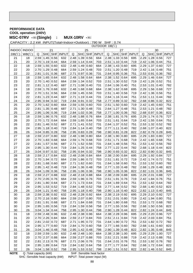
88
MSC-07RV - (Single) : MUX-10RV - E1E1
PERFORMANCE DATACOOL operation (240V)
INDOO INDOO 21 25 27 30DB(;) WB(;) Q SHC SHF INPUT Q SHC SHF INPUT Q SHC SHF INPUT Q SHC SHF INPUT
21 18 2.59 1.45 0.56 632 2.48 1.39 0.56 664 2.38 1.33 0.56 695 2.29 1.28 0.56 72721 20 2.70 1.19 0.44 664 2.59 1.14 0.44 703 2.51 1.10 0.44 719 2.42 1.06 0.44 75122 18 2.59 1.55 0.60 632 2.48 1.49 0.60 664 2.38 1.43 0.60 695 2.29 1.37 0.60 72722 20 2.70 1.29 0.48 664 2.59 1.24 0.48 703 2.51 1.20 0.48 719 2.42 1.16 0.48 75122 22 2.81 1.01 0.36 687 2.71 0.97 0.36 731 2.64 0.95 0.36 751 2.53 0.91 0.36 78223 18 2.59 1.65 0.64 632 2.48 1.58 0.64 664 2.38 1.52 0.64 695 2.29 1.46 0.64 72723 20 2.70 1.40 0.52 664 2.59 1.34 0.52 703 2.51 1.30 0.52 719 2.42 1.26 0.52 75123 22 2.81 1.12 0.40 687 2.71 1.08 0.40 731 2.64 1.06 0.40 751 2.53 1.01 0.40 78224 18 2.59 1.76 0.68 632 2.48 1.68 0.68 664 2.38 1.62 0.68 695 2.29 1.56 0.68 72724 20 2.70 1.51 0.56 664 2.59 1.45 0.56 703 2.51 1.40 0.56 719 2.42 1.36 0.56 75124 22 2.81 1.23 0.44 687 2.71 1.19 0.44 731 2.64 1.16 0.44 751 2.53 1.11 0.44 78224 24 2.95 0.94 0.32 719 2.84 0.91 0.32 758 2.77 0.89 0.32 782 2.68 0.86 0.32 82225 20 2.70 1.62 0.60 664 2.59 1.55 0.60 703 2.51 1.50 0.60 719 2.42 1.45 0.60 75125 22 2.81 1.35 0.48 687 2.71 1.30 0.48 731 2.64 1.27 0.48 751 2.53 1.21 0.48 78225 24 2.95 1.06 0.36 719 2.84 1.02 0.36 758 2.77 1.00 0.36 782 2.68 0.97 0.36 82226 18 2.59 1.96 0.76 632 2.48 1.88 0.76 664 2.38 1.81 0.76 695 2.29 1.74 0.76 72726 20 2.70 1.72 0.64 664 2.59 1.65 0.64 703 2.51 1.61 0.64 719 2.42 1.55 0.64 75126 22 2.81 1.46 0.52 687 2.71 1.41 0.52 731 2.64 1.37 0.52 751 2.53 1.32 0.52 78226 24 2.95 1.18 0.40 719 2.84 1.14 0.40 758 2.77 1.11 0.40 782 2.68 1.07 0.40 82226 26 3.04 0.85 0.28 758 2.95 0.83 0.28 798 2.90 0.81 0.28 822 2.82 0.79 0.28 84527 18 2.59 2.07 0.80 632 2.48 1.98 0.80 664 2.38 1.90 0.80 695 2.29 1.83 0.80 72727 20 2.70 1.83 0.68 664 2.59 1.76 0.68 703 2.51 1.71 0.68 719 2.42 1.65 0.68 75127 22 2.81 1.57 0.56 687 2.71 1.52 0.56 731 2.64 1.48 0.56 751 2.53 1.42 0.56 78227 24 2.95 1.30 0.44 719 2.84 1.25 0.44 758 2.77 1.22 0.44 782 2.68 1.18 0.44 82227 26 3.04 0.97 0.32 758 2.95 0.94 0.32 798 2.90 0.93 0.32 822 2.82 0.90 0.32 84528 18 2.59 2.17 0.84 632 2.48 2.08 0.84 664 2.38 2.00 0.84 695 2.29 1.92 0.84 72728 20 2.70 1.94 0.72 664 2.59 1.86 0.72 703 2.51 1.81 0.72 719 2.42 1.74 0.72 75128 22 2.81 1.68 0.60 687 2.71 1.62 0.60 731 2.64 1.58 0.60 751 2.53 1.52 0.60 78228 24 2.95 1.42 0.48 719 2.84 1.36 0.48 758 2.77 1.33 0.48 782 2.68 1.29 0.48 82228 26 3.04 1.09 0.36 758 2.95 1.06 0.36 798 2.90 1.05 0.36 822 2.82 1.01 0.36 84529 18 2.59 2.27 0.88 632 2.48 2.18 0.88 664 2.38 2.09 0.88 695 2.29 2.01 0.88 72729 20 2.70 2.05 0.76 664 2.59 1.96 0.76 703 2.51 1.91 0.76 719 2.42 1.84 0.76 75129 22 2.81 1.80 0.64 687 2.71 1.73 0.64 731 2.64 1.69 0.64 751 2.53 1.62 0.64 78229 24 2.95 1.53 0.52 719 2.84 1.48 0.52 758 2.77 1.44 0.52 782 2.68 1.40 0.52 82229 26 3.04 1.21 0.40 758 2.95 1.18 0.40 798 2.90 1.16 0.40 822 2.82 1.13 0.40 84530 18 2.59 2.38 0.92 632 2.48 2.28 0.92 664 2.38 2.19 0.92 695 2.29 2.10 0.92 72730 20 2.70 2.16 0.80 664 2.59 2.07 0.80 703 2.51 2.01 0.80 719 2.42 1.94 0.80 75130 22 2.81 1.91 0.68 687 2.71 1.84 0.68 731 2.64 1.80 0.68 751 2.53 1.72 0.68 78230 24 2.95 1.65 0.56 719 2.84 1.59 0.56 758 2.77 1.55 0.56 782 2.68 1.50 0.56 82230 26 3.04 1.34 0.44 758 2.95 1.30 0.44 798 2.90 1.28 0.44 822 2.82 1.24 0.44 84531 18 2.59 2.48 0.96 632 2.48 2.38 0.96 664 2.38 2.28 0.96 695 2.29 2.20 0.96 72731 20 2.70 2.26 0.84 664 2.59 2.17 0.84 703 2.51 2.11 0.84 719 2.42 2.03 0.84 75131 22 2.81 2.02 0.72 687 2.71 1.95 0.72 731 2.64 1.90 0.72 751 2.53 1.82 0.72 78231 24 2.95 1.77 0.60 719 2.84 1.70 0.60 758 2.77 1.66 0.60 782 2.68 1.61 0.60 82231 26 3.04 1.46 0.48 758 2.95 1.42 0.48 798 2.90 1.39 0.48 822 2.82 1.35 0.48 84532 18 2.59 2.59 1.00 632 2.48 2.48 1.00 664 2.38 2.38 1.00 695 2.29 2.29 1.00 72732 20 2.70 2.37 0.88 664 2.59 2.27 0.88 703 2.51 2.21 0.88 719 2.42 2.13 0.88 75132 22 2.81 2.13 0.76 687 2.71 2.06 0.76 731 2.64 2.01 0.76 751 2.53 1.92 0.76 78232 24 2.95 1.89 0.64 719 2.84 1.82 0.64 758 2.77 1.77 0.64 782 2.68 1.72 0.64 82232 26 3.04 1.58 0.52 758 2.95 1.53 0.52 798 2.90 1.51 0.52 822 2.82 1.46 0.52 845
CAPACITY : 2.2 kW INPUT(Total=Indoor+Outdoor) : 790 W SHF : 0.74OUTDOOR DB(;)
NOTE Q :Total capacity (kW) SHF :Sensible heat factorSHC :Sensible heat capacity (kW) INPUT :Total power input (W)

89
MSC-07RV - (Single) :MUX-10RV - E1E1
PERFORMANCE DATACOOL operation (240V)
OUTDOOR DB(;)INDOO INDOO 35 40 43DB(;) WB(;) Q SHC SHF INPUT Q SHC SHF INPUT
21 18 2.16 1.21 0.56 774 1.98 1.11 0.56 82221 20 2.27 1.00 0.44 806 2.11 0.93 0.44 84522 18 2.16 1.29 0.60 774 1.98 1.19 0.60 82222 20 2.27 1.09 0.48 806 2.11 1.01 0.48 84522 22 2.40 0.86 0.36 837 2.24 0.81 0.36 88523 18 2.16 1.38 0.64 774 1.98 1.27 0.64 82223 20 2.27 1.18 0.52 806 2.11 1.10 0.52 84523 22 2.40 0.96 0.40 837 2.24 0.90 0.40 88524 18 2.16 1.47 0.68 774 1.98 1.35 0.68 82224 20 2.27 1.27 0.56 806 2.11 1.18 0.56 84524 22 2.40 1.06 0.44 837 2.24 0.99 0.44 88524 24 2.53 0.81 0.32 869 2.38 0.76 0.32 90925 20 2.27 1.36 0.60 806 2.11 1.27 0.60 84525 22 2.40 1.15 0.48 837 2.24 1.08 0.48 88525 24 2.53 0.91 0.36 869 2.38 0.86 0.36 90926 18 2.16 1.64 0.76 774 1.98 1.50 0.76 82226 20 2.27 1.45 0.64 806 2.11 1.35 0.64 84526 22 2.40 1.25 0.52 837 2.24 1.17 0.52 88526 24 2.53 1.01 0.40 869 2.38 0.95 0.40 90926 26 2.66 0.75 0.28 901 2.51 0.70 0.28 94027 18 2.16 1.72 0.80 774 1.98 1.58 0.80 82227 20 2.27 1.54 0.68 806 2.11 1.44 0.68 84527 22 2.40 1.34 0.56 837 2.24 1.26 0.56 88527 24 2.53 1.11 0.44 869 2.38 1.05 0.44 90927 26 2.66 0.85 0.32 901 2.51 0.80 0.32 94028 18 2.16 1.81 0.84 774 1.98 1.66 0.84 82228 20 2.27 1.63 0.72 806 2.11 1.52 0.72 84528 22 2.40 1.44 0.60 837 2.24 1.35 0.60 88528 24 2.53 1.21 0.48 869 2.38 1.14 0.48 90928 26 2.66 0.96 0.36 901 2.51 0.90 0.36 94029 18 2.16 1.90 0.88 774 1.98 1.74 0.88 82229 20 2.27 1.72 0.76 806 2.11 1.61 0.76 84529 22 2.40 1.53 0.64 837 2.24 1.44 0.64 88529 24 2.53 1.32 0.52 869 2.38 1.24 0.52 90929 26 2.66 1.06 0.40 901 2.51 1.00 0.40 94030 18 2.16 1.98 0.92 774 1.98 1.82 0.92 82230 20 2.27 1.81 0.80 806 2.11 1.69 0.80 84530 22 2.40 1.63 0.68 837 2.24 1.53 0.68 88530 24 2.53 1.42 0.56 869 2.38 1.33 0.56 90930 26 2.66 1.17 0.44 901 2.51 1.10 0.44 94031 18 2.16 2.07 0.96 774 1.98 1.90 0.96 82231 20 2.27 1.90 0.84 806 2.11 1.77 0.84 84531 22 2.40 1.73 0.72 837 2.24 1.62 0.72 88531 24 2.53 1.52 0.60 869 2.38 1.43 0.60 90931 26 2.66 1.28 0.48 901 2.51 1.20 0.48 94032 18 2.16 2.16 1.00 774 1.98 1.98 1.00 82232 20 2.27 1.99 0.88 806 2.11 1.86 0.88 84532 22 2.40 1.82 0.76 837 2.24 1.71 0.76 88532 24 2.53 1.62 0.64 869 2.38 1.52 0.64 90932 26 2.66 1.38 0.52 901 2.51 1.30 0.52 940
CAPACITY : 2.2 kW INPUT(Total=Indoor+Outdoor) : 790 W SHF : 0.74
Q SHC SHF INPUT1.90 1.07 0.56 8372.04 0.90 0.44 8691.90 1.14 0.60 8372.04 0.98 0.48 8692.17 0.78 0.36 9011.90 1.22 0.64 8372.04 1.06 0.52 8692.17 0.87 0.40 9011.90 1.29 0.68 8372.04 1.14 0.56 8692.17 0.95 0.44 9012.31 0.74 0.32 9282.04 1.22 0.60 8692.17 1.04 0.48 9012.31 0.83 0.36 9281.90 1.45 0.76 8372.04 1.30 0.64 8692.17 1.13 0.52 9012.31 0.92 0.40 9282.43 0.68 0.28 9601.90 1.52 0.80 8372.04 1.38 0.68 8692.17 1.21 0.56 9012.31 1.02 0.44 9282.43 0.78 0.32 9601.90 1.60 0.84 8372.04 1.47 0.72 8692.17 1.30 0.60 9012.31 1.11 0.48 9282.43 0.88 0.36 9601.90 1.67 0.88 8372.04 1.55 0.76 8692.17 1.39 0.64 9012.31 1.20 0.52 9282.43 0.97 0.40 9601.90 1.75 0.92 8372.04 1.63 0.80 8692.17 1.47 0.68 9012.31 1.29 0.56 9282.43 1.07 0.44 9601.90 1.83 0.96 8372.04 1.71 0.84 8692.17 1.56 0.72 9012.31 1.39 0.60 9282.43 1.17 0.48 9601.90 1.90 1.00 8372.04 1.79 0.88 8692.17 1.65 0.76 9012.31 1.48 0.64 9282.43 1.26 0.52 960
NOTE Q :Total capacity (kW) SHF :Sensible heat factorSHC :Sensible heat capacity (kW) INPUT :Total power input (W)

90
MSC-09RV - (Single) : MUX-18RV - E1E1
PERFORMANCE DATACOOL operation (220V)
INDOO INDOO 21 25 27 30DB(;) WB(;) Q SHC SHF INPUT Q SHC SHF INPUT Q SHC SHF INPUT Q SHC SHF INPUT
21 18 2.70 1.49 0.55 632 2.59 1.42 0.55 664 2.48 1.37 0.55 695 2.39 1.32 0.55 72721 20 2.82 1.21 0.43 664 2.70 1.16 0.43 703 2.62 1.13 0.43 719 2.53 1.09 0.43 75122 18 2.70 1.59 0.59 632 2.59 1.53 0.59 664 2.48 1.47 0.59 695 2.39 1.41 0.59 72722 20 2.82 1.32 0.47 664 2.70 1.27 0.47 703 2.62 1.23 0.47 719 2.53 1.19 0.47 75122 22 2.93 1.03 0.35 687 2.83 0.99 0.35 731 2.76 0.97 0.35 751 2.65 0.93 0.35 78223 18 2.70 1.70 0.63 632 2.59 1.63 0.63 664 2.48 1.56 0.63 695 2.39 1.51 0.63 72723 20 2.82 1.44 0.51 664 2.70 1.38 0.51 703 2.62 1.34 0.51 719 2.53 1.29 0.51 75123 22 2.93 1.14 0.39 687 2.83 1.10 0.39 731 2.76 1.08 0.39 751 2.65 1.03 0.39 78224 18 2.70 1.81 0.67 632 2.59 1.73 0.67 664 2.48 1.66 0.67 695 2.39 1.60 0.67 72724 20 2.82 1.55 0.55 664 2.70 1.49 0.55 703 2.62 1.44 0.55 719 2.53 1.39 0.55 75124 22 2.93 1.26 0.43 687 2.83 1.22 0.43 731 2.76 1.19 0.43 751 2.65 1.14 0.43 78224 24 3.08 0.96 0.31 719 2.97 0.92 0.31 758 2.90 0.90 0.31 782 2.81 0.87 0.31 82225 20 2.82 1.66 0.59 664 2.70 1.59 0.59 703 2.62 1.55 0.59 719 2.53 1.49 0.59 75125 22 2.93 1.38 0.47 687 2.83 1.33 0.47 731 2.76 1.30 0.47 751 2.65 1.24 0.47 78225 24 3.08 1.08 0.35 719 2.97 1.04 0.35 758 2.90 1.01 0.35 782 2.81 0.98 0.35 82226 18 2.70 2.03 0.75 632 2.59 1.94 0.75 664 2.48 1.86 0.75 695 2.39 1.79 0.75 72726 20 2.82 1.78 0.63 664 2.70 1.70 0.63 703 2.62 1.65 0.63 719 2.53 1.59 0.63 75126 22 2.93 1.50 0.51 687 2.83 1.44 0.51 731 2.76 1.41 0.51 751 2.65 1.35 0.51 78226 24 3.08 1.20 0.39 719 2.97 1.16 0.39 758 2.90 1.13 0.39 782 2.81 1.09 0.39 82226 26 3.17 0.86 0.27 758 3.08 0.83 0.27 798 3.04 0.82 0.27 822 2.94 0.79 0.27 84527 18 2.70 2.13 0.79 632 2.59 2.04 0.79 664 2.48 1.96 0.79 695 2.39 1.89 0.79 72727 20 2.82 1.89 0.67 664 2.70 1.81 0.67 703 2.62 1.76 0.67 719 2.53 1.70 0.67 75127 22 2.93 1.61 0.55 687 2.83 1.56 0.55 731 2.76 1.52 0.55 751 2.65 1.45 0.55 78227 24 3.08 1.33 0.43 719 2.97 1.28 0.43 758 2.90 1.25 0.43 782 2.81 1.21 0.43 82227 26 3.17 0.98 0.31 758 3.08 0.96 0.31 798 3.04 0.94 0.31 822 2.94 0.91 0.31 84528 18 2.70 2.24 0.83 632 2.59 2.15 0.83 664 2.48 2.06 0.83 695 2.39 1.99 0.83 72728 20 2.82 2.00 0.71 664 2.70 1.92 0.71 703 2.62 1.86 0.71 719 2.53 1.80 0.71 75128 22 2.93 1.73 0.59 687 2.83 1.67 0.59 731 2.76 1.63 0.59 751 2.65 1.56 0.59 78228 24 3.08 1.45 0.47 719 2.97 1.39 0.47 758 2.90 1.36 0.47 782 2.81 1.32 0.47 82228 26 3.17 1.11 0.35 758 3.08 1.08 0.35 798 3.04 1.06 0.35 822 2.94 1.03 0.35 84529 18 2.70 2.35 0.87 632 2.59 2.25 0.87 664 2.48 2.16 0.87 695 2.39 2.08 0.87 72729 20 2.82 2.11 0.75 664 2.70 2.03 0.75 703 2.62 1.97 0.75 719 2.53 1.90 0.75 75129 22 2.93 1.85 0.63 687 2.83 1.78 0.63 731 2.76 1.74 0.63 751 2.65 1.67 0.63 78229 24 3.08 1.57 0.51 719 2.97 1.51 0.51 758 2.90 1.48 0.51 782 2.81 1.43 0.51 82229 26 3.17 1.24 0.39 758 3.08 1.20 0.39 798 3.04 1.18 0.39 822 2.94 1.15 0.39 84530 18 2.70 2.46 0.91 632 2.59 2.35 0.91 664 2.48 2.26 0.91 695 2.39 2.18 0.91 72730 20 2.82 2.23 0.79 664 2.70 2.13 0.79 703 2.62 2.07 0.79 719 2.53 2.00 0.79 75130 22 2.93 1.96 0.67 687 2.83 1.90 0.67 731 2.76 1.85 0.67 751 2.65 1.77 0.67 78230 24 3.08 1.70 0.55 719 2.97 1.63 0.55 758 2.90 1.59 0.55 782 2.81 1.54 0.55 82230 26 3.17 1.36 0.43 758 3.08 1.33 0.43 798 3.04 1.31 0.43 822 2.94 1.27 0.43 84531 18 2.70 2.57 0.95 632 2.59 2.46 0.95 664 2.48 2.36 0.95 695 2.39 2.27 0.95 72731 20 2.82 2.34 0.83 664 2.70 2.24 0.83 703 2.62 2.18 0.83 719 2.53 2.10 0.83 75131 22 2.93 2.08 0.71 687 2.83 2.01 0.71 731 2.76 1.96 0.71 751 2.65 1.88 0.71 78231 24 3.08 1.82 0.59 719 2.97 1.75 0.59 758 2.90 1.71 0.59 782 2.81 1.66 0.59 82231 26 3.17 1.49 0.47 758 3.08 1.45 0.47 798 3.04 1.43 0.47 822 2.94 1.38 0.47 84532 18 2.70 2.68 0.99 632 2.59 2.56 0.99 664 2.48 2.46 0.99 695 2.39 2.37 0.99 72732 20 2.82 2.45 0.87 664 2.70 2.35 0.87 703 2.62 2.28 0.87 719 2.53 2.20 0.87 75132 22 2.93 2.20 0.75 687 2.83 2.12 0.75 731 2.76 2.07 0.75 751 2.65 1.98 0.75 78232 24 3.08 1.94 0.63 719 2.97 1.87 0.63 758 2.90 1.83 0.63 782 2.81 1.77 0.63 82232 26 3.17 1.62 0.51 758 3.08 1.57 0.51 798 3.04 1.55 0.51 822 2.94 1.50 0.51 845
OUTDOOR DB(;)CAPACITY : 2.3 kW INPUT(Total=Indoor+Outdoor) : 790 W SHF : 0.73
NOTE Q :Total capacity (kW) SHF :Sensible heat factorSHC :Sensible heat capacity (kW) INPUT :Total power input (W)

91
MSC-09RV - (Single) : MUX-18RV - E1E1
PERFORMANCE DATACOOL operation (220V)
INDOO INDOO 35 40 43DB(;) WB(;) Q SHC SHF INPUT Q SHC SHF INPUT
21 18 2.25 1.24 0.55 774 2.07 1.14 0.55 82221 20 2.37 1.02 0.43 806 2.21 0.95 0.43 84522 18 2.25 1.33 0.59 774 2.07 1.22 0.59 82222 20 2.37 1.11 0.47 806 2.21 1.04 0.47 84522 22 2.51 0.88 0.35 837 2.35 0.82 0.35 88523 18 2.25 1.42 0.63 774 2.07 1.30 0.63 82223 20 2.37 1.21 0.51 806 2.21 1.13 0.51 84523 22 2.51 0.98 0.39 837 2.35 0.91 0.39 88524 18 2.25 1.51 0.67 774 2.07 1.39 0.67 82224 20 2.37 1.30 0.55 806 2.21 1.21 0.55 84524 22 2.51 1.08 0.43 837 2.35 1.01 0.43 88524 24 2.65 0.82 0.31 869 2.48 0.77 0.31 90925 20 2.37 1.40 0.59 806 2.21 1.30 0.59 84525 22 2.51 1.18 0.47 837 2.35 1.10 0.47 88525 24 2.65 0.93 0.35 869 2.48 0.87 0.35 90926 18 2.25 1.69 0.75 774 2.07 1.55 0.75 82226 20 2.37 1.49 0.63 806 2.21 1.39 0.63 84526 22 2.51 1.28 0.51 837 2.35 1.20 0.51 88526 24 2.65 1.03 0.39 869 2.48 0.97 0.39 90926 26 2.78 0.75 0.27 901 2.62 0.71 0.27 94027 18 2.25 1.78 0.79 774 2.07 1.64 0.79 82227 20 2.37 1.59 0.67 806 2.21 1.48 0.67 84527 22 2.51 1.38 0.55 837 2.35 1.29 0.55 88527 24 2.65 1.14 0.43 869 2.48 1.07 0.43 90927 26 2.78 0.86 0.31 901 2.62 0.81 0.31 94028 18 2.25 1.87 0.83 774 2.07 1.72 0.83 82228 20 2.37 1.68 0.71 806 2.21 1.57 0.71 84528 22 2.51 1.48 0.59 837 2.35 1.38 0.59 88528 24 2.65 1.24 0.47 869 2.48 1.17 0.47 90928 26 2.78 0.97 0.35 901 2.62 0.92 0.35 94029 18 2.25 1.96 0.87 774 2.07 1.80 0.87 82229 20 2.37 1.78 0.75 806 2.21 1.66 0.75 84529 22 2.51 1.58 0.63 837 2.35 1.48 0.63 88529 24 2.65 1.35 0.51 869 2.48 1.27 0.51 90929 26 2.78 1.09 0.39 901 2.62 1.02 0.39 94030 18 2.25 2.05 0.91 774 2.07 1.88 0.91 82230 20 2.37 1.87 0.79 806 2.21 1.74 0.79 84530 22 2.51 1.68 0.67 837 2.35 1.57 0.67 88530 24 2.65 1.45 0.55 869 2.48 1.37 0.55 90930 26 2.78 1.20 0.43 901 2.62 1.13 0.43 94031 18 2.25 2.14 0.95 774 2.07 1.97 0.95 82231 20 2.37 1.97 0.83 806 2.21 1.83 0.83 84531 22 2.51 1.78 0.71 837 2.35 1.67 0.71 88531 24 2.65 1.56 0.59 869 2.48 1.47 0.59 90931 26 2.78 1.31 0.47 901 2.62 1.23 0.47 94032 18 2.25 2.23 0.99 774 2.07 2.05 0.99 82232 20 2.37 2.06 0.87 806 2.21 1.92 0.87 84532 22 2.51 1.88 0.75 837 2.35 1.76 0.75 88532 24 2.65 1.67 0.63 869 2.48 1.56 0.63 90932 26 2.78 1.42 0.51 901 2.62 1.34 0.51 940
OUTDOOR DB(;)CAPACITY : 2.3 kW INPUT(Total=Indoor+Outdoor) : 790 W SHF : 0.73
Q SHC SHF INPUT1.99 1.09 0.55 8372.13 0.91 0.43 8691.99 1.17 0.59 8372.13 1.00 0.47 8692.27 0.79 0.35 9011.99 1.25 0.63 8372.13 1.09 0.51 8692.27 0.88 0.39 9011.99 1.33 0.67 8372.13 1.17 0.55 8692.27 0.97 0.43 9012.42 0.75 0.31 9282.13 1.26 0.59 8692.27 1.06 0.47 9012.42 0.85 0.35 9281.99 1.49 0.75 8372.13 1.34 0.63 8692.27 1.16 0.51 9012.42 0.94 0.39 9282.54 0.69 0.27 9601.99 1.57 0.79 8372.13 1.43 0.67 8692.27 1.25 0.55 9012.42 1.04 0.43 9282.54 0.79 0.31 9601.99 1.65 0.83 8372.13 1.51 0.71 8692.27 1.34 0.59 9012.42 1.14 0.47 9282.54 0.89 0.35 9601.99 1.73 0.87 8372.13 1.60 0.75 8692.27 1.43 0.63 9012.42 1.23 0.51 9282.54 0.99 0.39 9601.99 1.81 0.91 8372.13 1.68 0.79 8692.27 1.52 0.67 9012.42 1.33 0.55 9282.54 1.09 0.43 9601.99 1.89 0.95 8372.13 1.77 0.83 8692.27 1.61 0.71 9012.42 1.42 0.59 9282.54 1.19 0.47 9601.99 1.97 0.99 8372.13 1.85 0.87 8692.27 1.70 0.75 9012.42 1.52 0.63 9282.54 1.30 0.51 960
NOTE Q :Total capacity (kW) SHF :Sensible heat factorSHC :Sensible heat capacity (kW) INPUT :Total power input (W)

92
MSC-09RV - (Single) : MUX-18RV - E1E1
PERFORMANCE DATACOOL operation (240V)
INDOOR INDOOR 21 25 27 30DB(;) WB(;) Q SHC SHF INPUT Q SHC SHF INPUT Q SHC SHF INPUT Q SHC SHF INPUT
21 18 2.70 1.49 0.55 664 2.59 1.42 0.55 697 2.48 1.37 0.55 730 2.39 1.32 0.55 76421 20 2.82 1.21 0.43 697 2.70 1.16 0.43 739 2.62 1.13 0.43 755 2.53 1.09 0.43 78922 18 2.70 1.59 0.59 664 2.59 1.53 0.59 697 2.48 1.47 0.59 730 2.39 1.41 0.59 76422 20 2.82 1.32 0.47 697 2.70 1.27 0.47 739 2.62 1.23 0.47 755 2.53 1.19 0.47 78922 22 2.93 1.03 0.35 722 2.83 0.99 0.35 768 2.76 0.97 0.35 789 2.65 0.93 0.35 82223 18 2.70 1.70 0.63 664 2.59 1.63 0.63 697 2.48 1.56 0.63 730 2.39 1.51 0.63 76423 20 2.82 1.44 0.51 697 2.70 1.38 0.51 739 2.62 1.34 0.51 755 2.53 1.29 0.51 78923 22 2.93 1.14 0.39 722 2.83 1.10 0.39 768 2.76 1.08 0.39 789 2.65 1.03 0.39 82224 18 2.70 1.81 0.67 664 2.59 1.73 0.67 697 2.48 1.66 0.67 730 2.39 1.60 0.67 76424 20 2.82 1.55 0.55 697 2.70 1.49 0.55 739 2.62 1.44 0.55 755 2.53 1.39 0.55 78924 22 2.93 1.26 0.43 722 2.83 1.22 0.43 768 2.76 1.19 0.43 789 2.65 1.14 0.43 82224 24 3.08 0.96 0.31 755 2.97 0.92 0.31 797 2.90 0.90 0.31 822 2.81 0.87 0.31 86325 20 2.82 1.66 0.59 697 2.70 1.59 0.59 739 2.62 1.55 0.59 755 2.53 1.49 0.59 78925 22 2.93 1.38 0.47 722 2.83 1.33 0.47 768 2.76 1.30 0.47 789 2.65 1.24 0.47 82225 24 3.08 1.08 0.35 755 2.97 1.04 0.35 797 2.90 1.01 0.35 822 2.81 0.98 0.35 86326 18 2.70 2.03 0.75 664 2.59 1.94 0.75 697 2.48 1.86 0.75 730 2.39 1.79 0.75 76426 20 2.82 1.78 0.63 697 2.70 1.70 0.63 739 2.62 1.65 0.63 755 2.53 1.59 0.63 78926 22 2.93 1.50 0.51 722 2.83 1.44 0.51 768 2.76 1.41 0.51 789 2.65 1.35 0.51 82226 24 3.08 1.20 0.39 755 2.97 1.16 0.39 797 2.90 1.13 0.39 822 2.81 1.09 0.39 86326 26 3.17 0.86 0.27 797 3.08 0.83 0.27 838 3.04 0.82 0.27 863 2.94 0.79 0.27 88827 18 2.70 2.13 0.79 664 2.59 2.04 0.79 697 2.48 1.96 0.79 730 2.39 1.89 0.79 76427 20 2.82 1.89 0.67 697 2.70 1.81 0.67 739 2.62 1.76 0.67 755 2.53 1.70 0.67 78927 22 2.93 1.61 0.55 722 2.83 1.56 0.55 768 2.76 1.52 0.55 789 2.65 1.45 0.55 82227 24 3.08 1.33 0.43 755 2.97 1.28 0.43 797 2.90 1.25 0.43 822 2.81 1.21 0.43 86327 26 3.17 0.98 0.31 797 3.08 0.96 0.31 838 3.04 0.94 0.31 863 2.94 0.91 0.31 88828 18 2.70 2.24 0.83 664 2.59 2.15 0.83 697 2.48 2.06 0.83 730 2.39 1.99 0.83 76428 20 2.82 2.00 0.71 697 2.70 1.92 0.71 739 2.62 1.86 0.71 755 2.53 1.80 0.71 78928 22 2.93 1.73 0.59 722 2.83 1.67 0.59 768 2.76 1.63 0.59 789 2.65 1.56 0.59 82228 24 3.08 1.45 0.47 755 2.97 1.39 0.47 797 2.90 1.36 0.47 822 2.81 1.32 0.47 86328 26 3.17 1.11 0.35 797 3.08 1.08 0.35 838 3.04 1.06 0.35 863 2.94 1.03 0.35 88829 18 2.70 2.35 0.87 664 2.59 2.25 0.87 697 2.48 2.16 0.87 730 2.39 2.08 0.87 76429 20 2.82 2.11 0.75 697 2.70 2.03 0.75 739 2.62 1.97 0.75 755 2.53 1.90 0.75 78929 22 2.93 1.85 0.63 722 2.83 1.78 0.63 768 2.76 1.74 0.63 789 2.65 1.67 0.63 82229 24 3.08 1.57 0.51 755 2.97 1.51 0.51 797 2.90 1.48 0.51 822 2.81 1.43 0.51 86329 26 3.17 1.24 0.39 797 3.08 1.20 0.39 838 3.04 1.18 0.39 863 2.94 1.15 0.39 88830 18 2.70 2.46 0.91 664 2.59 2.35 0.91 697 2.48 2.26 0.91 730 2.39 2.18 0.91 76430 20 2.82 2.23 0.79 697 2.70 2.13 0.79 739 2.62 2.07 0.79 755 2.53 2.00 0.79 78930 22 2.93 1.96 0.67 722 2.83 1.90 0.67 768 2.76 1.85 0.67 789 2.65 1.77 0.67 82230 24 3.08 1.70 0.55 755 2.97 1.63 0.55 797 2.90 1.59 0.55 822 2.81 1.54 0.55 86330 26 3.17 1.36 0.43 797 3.08 1.33 0.43 838 3.04 1.31 0.43 863 2.94 1.27 0.43 88831 18 2.70 2.57 0.95 664 2.59 2.46 0.95 697 2.48 2.36 0.95 730 2.39 2.27 0.95 76431 20 2.82 2.34 0.83 697 2.70 2.24 0.83 739 2.62 2.18 0.83 755 2.53 2.10 0.83 78931 22 2.93 2.08 0.71 722 2.83 2.01 0.71 768 2.76 1.96 0.71 789 2.65 1.88 0.71 82231 24 3.08 1.82 0.59 755 2.97 1.75 0.59 797 2.90 1.71 0.59 822 2.81 1.66 0.59 86331 26 3.17 1.49 0.47 797 3.08 1.45 0.47 838 3.04 1.43 0.47 863 2.94 1.38 0.47 88832 18 2.70 2.68 0.99 664 2.59 2.56 0.99 697 2.48 2.46 0.99 730 2.39 2.37 0.99 76432 20 2.82 2.45 0.87 697 2.70 2.35 0.87 739 2.62 2.28 0.87 755 2.53 2.20 0.87 78932 22 2.93 2.20 0.75 722 2.83 2.12 0.75 768 2.76 2.07 0.75 789 2.65 1.98 0.75 82232 24 3.08 1.94 0.63 755 2.97 1.87 0.63 797 2.90 1.83 0.63 822 2.81 1.77 0.63 86332 26 3.17 1.62 0.51 797 3.08 1.57 0.51 838 3.04 1.55 0.51 863 2.94 1.50 0.51 888
OUTDOOR DB(;)CAPACITY : 2.3 kW INPUT(Total=Indoor+Outdoor) : 830 W SHF : 0.73
NOTE Q :Total capacity (kW) SHF :Sensible heat factorSHC :Sensible heat capacity (kW) INPUT :Total power input (W)

93
MSC-09RV - (Single) : MUX-18RV - E1E1
PERFORMANCE DATACOOL operation (240V)
OUTDOOR DB(;)INDOOR INDOOR 35 40 43DB(;) WB(;) Q SHC SHF INPUT Q SHC SHF INPUT
21 18 2.25 1.24 0.55 813 2.07 1.14 0.55 86321 20 2.37 1.02 0.43 847 2.21 0.95 0.43 88822 18 2.25 1.33 0.59 813 2.07 1.22 0.59 86322 20 2.37 1.11 0.47 847 2.21 1.04 0.47 88822 22 2.51 0.88 0.35 880 2.35 0.82 0.35 93023 18 2.25 1.42 0.63 813 2.07 1.30 0.63 86323 20 2.37 1.21 0.51 847 2.21 1.13 0.51 88823 22 2.51 0.98 0.39 880 2.35 0.91 0.39 93024 18 2.25 1.51 0.67 813 2.07 1.39 0.67 86324 20 2.37 1.30 0.55 847 2.21 1.21 0.55 88824 22 2.51 1.08 0.43 880 2.35 1.01 0.43 93024 24 2.65 0.82 0.31 913 2.48 0.77 0.31 95525 20 2.37 1.40 0.59 847 2.21 1.30 0.59 88825 22 2.51 1.18 0.47 880 2.35 1.10 0.47 93025 24 2.65 0.93 0.35 913 2.48 0.87 0.35 95526 18 2.25 1.69 0.75 813 2.07 1.55 0.75 86326 20 2.37 1.49 0.63 847 2.21 1.39 0.63 88826 22 2.51 1.28 0.51 880 2.35 1.20 0.51 93026 24 2.65 1.03 0.39 913 2.48 0.97 0.39 95526 26 2.78 0.75 0.27 946 2.62 0.71 0.27 98827 18 2.25 1.78 0.79 813 2.07 1.64 0.79 86327 20 2.37 1.59 0.67 847 2.21 1.48 0.67 88827 22 2.51 1.38 0.55 880 2.35 1.29 0.55 93027 24 2.65 1.14 0.43 913 2.48 1.07 0.43 95527 26 2.78 0.86 0.31 946 2.62 0.81 0.31 98828 18 2.25 1.87 0.83 813 2.07 1.72 0.83 86328 20 2.37 1.68 0.71 847 2.21 1.57 0.71 88828 22 2.51 1.48 0.59 880 2.35 1.38 0.59 93028 24 2.65 1.24 0.47 913 2.48 1.17 0.47 95528 26 2.78 0.97 0.35 946 2.62 0.92 0.35 98829 18 2.25 1.96 0.87 813 2.07 1.80 0.87 86329 20 2.37 1.78 0.75 847 2.21 1.66 0.75 88829 22 2.51 1.58 0.63 880 2.35 1.48 0.63 93029 24 2.65 1.35 0.51 913 2.48 1.27 0.51 95529 26 2.78 1.09 0.39 946 2.62 1.02 0.39 98830 18 2.25 2.05 0.91 813 2.07 1.88 0.91 86330 20 2.37 1.87 0.79 847 2.21 1.74 0.79 88830 22 2.51 1.68 0.67 880 2.35 1.57 0.67 93030 24 2.65 1.45 0.55 913 2.48 1.37 0.55 95530 26 2.78 1.20 0.43 946 2.62 1.13 0.43 98831 18 2.25 2.14 0.95 813 2.07 1.97 0.95 86331 20 2.37 1.97 0.83 847 2.21 1.83 0.83 88831 22 2.51 1.78 0.71 880 2.35 1.67 0.71 93031 24 2.65 1.56 0.59 913 2.48 1.47 0.59 95531 26 2.78 1.31 0.47 946 2.62 1.23 0.47 98832 18 2.25 2.23 0.99 813 2.07 2.05 0.99 86332 20 2.37 2.06 0.87 847 2.21 1.92 0.87 88832 22 2.51 1.88 0.75 880 2.35 1.76 0.75 93032 24 2.65 1.67 0.63 913 2.48 1.56 0.63 95532 26 2.78 1.42 0.51 946 2.62 1.34 0.51 988
CAPACITY : 2.3 kW INPUT(Total=Indoor+Outdoor) : 830 W SHF : 0.73
Q SHC SHF INPUT1.99 1.09 0.55 8802.13 0.91 0.43 9131.99 1.17 0.59 8802.13 1.00 0.47 9132.27 0.79 0.35 9461.99 1.25 0.63 8802.13 1.09 0.51 9132.27 0.88 0.39 9461.99 1.33 0.67 8802.13 1.17 0.55 9132.27 0.97 0.43 9462.42 0.75 0.31 9752.13 1.26 0.59 9132.27 1.06 0.47 9462.42 0.85 0.35 9751.99 1.49 0.75 8802.13 1.34 0.63 9132.27 1.16 0.51 9462.42 0.94 0.39 9752.54 0.69 0.27 10081.99 1.57 0.79 8802.13 1.43 0.67 9132.27 1.25 0.55 9462.42 1.04 0.43 9752.54 0.79 0.31 10081.99 1.65 0.83 8802.13 1.51 0.71 9132.27 1.34 0.59 9462.42 1.14 0.47 9752.54 0.89 0.35 10081.99 1.73 0.87 8802.13 1.60 0.75 9132.27 1.43 0.63 9462.42 1.23 0.51 9752.54 0.99 0.39 10081.99 1.81 0.91 8802.13 1.68 0.79 9132.27 1.52 0.67 9462.42 1.33 0.55 9752.54 1.09 0.43 10081.99 1.89 0.95 8802.13 1.77 0.83 9132.27 1.61 0.71 9462.42 1.42 0.59 9752.54 1.19 0.47 10081.99 1.97 0.99 8802.13 1.85 0.87 9132.27 1.70 0.75 9462.42 1.52 0.63 9752.54 1.30 0.51 1008
NOTE Q :Total capacity (kW) SHF :Sensible heat factorSHC :Sensible heat capacity (kW) INPUT :Total power input (W)

94
MSC-09RV - (Single) : MUX-24RV - E1E1
PERFORMANCE DATACOOL operation (220V)
INDOOR INDOOR 21 25 27 30DB(;) WB(;) Q SHC SHF INPUT Q SHC SHF INPUT Q SHC SHF INPUT Q SHC SHF INPUT
21 18 3.06 1.56 0.51 780 2.93 1.49 0.51 819 2.81 1.43 0.51 858 2.70 1.38 0.51 89721 20 3.19 1.24 0.39 819 3.06 1.19 0.39 868 2.96 1.16 0.39 887 2.86 1.12 0.39 92622 18 3.06 1.68 0.55 780 2.93 1.61 0.55 819 2.81 1.54 0.55 858 2.70 1.49 0.55 89722 20 3.19 1.37 0.43 819 3.06 1.31 0.43 868 2.96 1.27 0.43 887 2.86 1.23 0.43 92622 22 3.32 1.03 0.31 848 3.20 0.99 0.31 902 3.12 0.97 0.31 926 2.99 0.93 0.31 96523 18 3.06 1.80 0.59 780 2.93 1.73 0.59 819 2.81 1.66 0.59 858 2.70 1.60 0.59 89723 20 3.19 1.50 0.47 819 3.06 1.44 0.47 868 2.96 1.39 0.47 887 2.86 1.34 0.47 92623 22 3.32 1.16 0.35 848 3.20 1.12 0.35 902 3.12 1.09 0.35 926 2.99 1.05 0.35 96524 18 3.06 1.92 0.63 780 2.93 1.84 0.63 819 2.81 1.77 0.63 858 2.70 1.70 0.63 89724 20 3.19 1.62 0.51 819 3.06 1.56 0.51 868 2.96 1.51 0.51 887 2.86 1.46 0.51 92624 22 3.32 1.29 0.39 848 3.20 1.25 0.39 902 3.12 1.22 0.39 926 2.99 1.17 0.39 96524 24 3.48 0.94 0.27 887 3.35 0.91 0.27 936 3.28 0.88 0.27 965 3.17 0.86 0.27 101425 20 3.19 1.75 0.55 819 3.06 1.68 0.55 868 2.96 1.63 0.55 887 2.86 1.57 0.55 92625 22 3.32 1.43 0.43 848 3.20 1.38 0.43 902 3.12 1.34 0.43 926 2.99 1.29 0.43 96525 24 3.48 1.08 0.31 887 3.35 1.04 0.31 936 3.28 1.02 0.31 965 3.17 0.98 0.31 101426 18 3.06 2.17 0.71 780 2.93 2.08 0.71 819 2.81 1.99 0.71 858 2.70 1.92 0.71 89726 20 3.19 1.88 0.59 819 3.06 1.80 0.59 868 2.96 1.75 0.59 887 2.86 1.69 0.59 92626 22 3.32 1.56 0.47 848 3.20 1.50 0.47 902 3.12 1.47 0.47 926 2.99 1.41 0.47 96526 24 3.48 1.22 0.35 887 3.35 1.17 0.35 936 3.28 1.15 0.35 965 3.17 1.11 0.35 101426 26 3.59 0.83 0.23 936 3.48 0.80 0.23 985 3.43 0.79 0.23 1014 3.33 0.77 0.23 104327 18 3.06 2.29 0.75 780 2.93 2.19 0.75 819 2.81 2.11 0.75 858 2.70 2.03 0.75 89727 20 3.19 2.01 0.63 819 3.06 1.92 0.63 868 2.96 1.87 0.63 887 2.86 1.80 0.63 92627 22 3.32 1.69 0.51 848 3.20 1.63 0.51 902 3.12 1.59 0.51 926 2.99 1.52 0.51 96527 24 3.48 1.36 0.39 887 3.35 1.31 0.39 936 3.28 1.28 0.39 965 3.17 1.24 0.39 101427 26 3.59 0.97 0.27 936 3.48 0.94 0.27 985 3.43 0.93 0.27 1014 3.33 0.90 0.27 104328 18 3.06 2.41 0.79 780 2.93 2.31 0.79 819 2.81 2.22 0.79 858 2.70 2.14 0.79 89728 20 3.19 2.13 0.67 819 3.06 2.05 0.67 868 2.96 1.99 0.67 887 2.86 1.92 0.67 92628 22 3.32 1.82 0.55 848 3.20 1.76 0.55 902 3.12 1.72 0.55 926 2.99 1.64 0.55 96528 24 3.48 1.50 0.43 887 3.35 1.44 0.43 936 3.28 1.41 0.43 965 3.17 1.36 0.43 101428 26 3.59 1.11 0.31 936 3.48 1.08 0.31 985 3.43 1.06 0.31 1014 3.33 1.03 0.31 104329 18 3.06 2.54 0.83 780 2.93 2.43 0.83 819 2.81 2.33 0.83 858 2.70 2.24 0.83 89729 20 3.19 2.26 0.71 819 3.06 2.17 0.71 868 2.96 2.10 0.71 887 2.86 2.03 0.71 92629 22 3.32 1.96 0.59 848 3.20 1.89 0.59 902 3.12 1.84 0.59 926 2.99 1.76 0.59 96529 24 3.48 1.64 0.47 887 3.35 1.58 0.47 936 3.28 1.54 0.47 965 3.17 1.49 0.47 101429 26 3.59 1.26 0.35 936 3.48 1.22 0.35 985 3.43 1.20 0.35 1014 3.33 1.16 0.35 104330 18 3.06 2.66 0.87 780 2.93 2.54 0.87 819 2.81 2.44 0.87 858 2.70 2.35 0.87 89730 20 3.19 2.39 0.75 819 3.06 2.29 0.75 868 2.96 2.22 0.75 887 2.86 2.15 0.75 92630 22 3.32 2.09 0.63 848 3.20 2.01 0.63 902 3.12 1.97 0.63 926 2.99 1.88 0.63 96530 24 3.48 1.78 0.51 887 3.35 1.71 0.51 936 3.28 1.67 0.51 965 3.17 1.62 0.51 101430 26 3.59 1.40 0.39 936 3.48 1.36 0.39 985 3.43 1.34 0.39 1014 3.33 1.30 0.39 104331 18 3.06 2.78 0.91 780 2.93 2.66 0.91 819 2.81 2.56 0.91 858 2.70 2.46 0.91 89731 20 3.19 2.52 0.79 819 3.06 2.41 0.79 868 2.96 2.34 0.79 887 2.86 2.26 0.79 92631 22 3.32 2.22 0.67 848 3.20 2.14 0.67 902 3.12 2.09 0.67 926 2.99 2.00 0.67 96531 24 3.48 1.92 0.55 887 3.35 1.84 0.55 936 3.28 1.80 0.55 965 3.17 1.74 0.55 101431 26 3.59 1.54 0.43 936 3.48 1.50 0.43 985 3.43 1.48 0.43 1014 3.33 1.43 0.43 104332 18 3.06 2.90 0.95 780 2.93 2.78 0.95 819 2.81 2.67 0.95 858 2.70 2.57 0.95 89732 20 3.19 2.64 0.83 819 3.06 2.54 0.83 868 2.96 2.46 0.83 887 2.86 2.37 0.83 92632 22 3.32 2.35 0.71 848 3.20 2.27 0.71 902 3.12 2.22 0.71 926 2.99 2.12 0.71 96532 24 3.48 2.06 0.59 887 3.35 1.98 0.59 936 3.28 1.93 0.59 965 3.17 1.87 0.59 101432 26 3.59 1.69 0.47 936 3.48 1.64 0.47 985 3.43 1.61 0.47 1014 3.33 1.56 0.47 1043
OUTDOOR DB(;)
CAPACITY : 2.6 kW INPUT(Total=Indoor+Outdoor) : 975 W SHF : 0.69
NOTE Q :Total capacity (kW) SHF :Sensible heat factorSHC :Sensible heat capacity (kW) INPUT :Total power input (W)

95
MSC-09RV - (Single) : MUX-24RV - E1E1
PERFORMANCE DATACOOL operation (220V)
INDOOR INDOOR 35 40 43DB(;) WB(;) Q SHC SHF INPUT Q SHC SHF INPUT
21 18 2.55 1.30 0.51 956 2.34 1.19 0.51 101421 20 2.68 1.04 0.39 995 2.50 0.97 0.39 104322 18 2.55 1.40 0.55 956 2.34 1.29 0.55 101422 20 2.68 1.15 0.43 995 2.50 1.07 0.43 104322 22 2.83 0.88 0.31 1034 2.65 0.82 0.31 109223 18 2.55 1.50 0.59 956 2.34 1.38 0.59 101423 20 2.68 1.26 0.47 995 2.50 1.17 0.47 104323 22 2.83 0.99 0.35 1034 2.65 0.93 0.35 109224 18 2.55 1.61 0.63 956 2.34 1.47 0.63 101424 20 2.68 1.37 0.51 995 2.50 1.27 0.51 104324 22 2.83 1.11 0.39 1034 2.65 1.03 0.39 109224 24 2.99 0.81 0.27 1073 2.81 0.76 0.27 112125 20 2.68 1.47 0.55 995 2.50 1.37 0.55 104325 22 2.83 1.22 0.43 1034 2.65 1.14 0.43 109225 24 2.99 0.93 0.31 1073 2.81 0.87 0.31 112126 18 2.55 1.81 0.71 956 2.34 1.66 0.71 101426 20 2.68 1.58 0.59 995 2.50 1.47 0.59 104326 22 2.83 1.33 0.47 1034 2.65 1.25 0.47 109226 24 2.99 1.05 0.35 1073 2.81 0.98 0.35 112126 26 3.15 0.72 0.23 1112 2.96 0.68 0.23 116027 18 2.55 1.91 0.75 956 2.34 1.76 0.75 101427 20 2.68 1.69 0.63 995 2.50 1.57 0.63 104327 22 2.83 1.45 0.51 1034 2.65 1.35 0.51 109227 24 2.99 1.17 0.39 1073 2.81 1.10 0.39 112127 26 3.15 0.85 0.27 1112 2.96 0.80 0.27 116028 18 2.55 2.01 0.79 956 2.34 1.85 0.79 101428 20 2.68 1.79 0.67 995 2.50 1.67 0.67 104328 22 2.83 1.56 0.55 1034 2.65 1.46 0.55 109228 24 2.99 1.29 0.43 1073 2.81 1.21 0.43 112128 26 3.15 0.98 0.31 1112 2.96 0.92 0.31 116029 18 2.55 2.11 0.83 956 2.34 1.94 0.83 101429 20 2.68 1.90 0.71 995 2.50 1.77 0.71 104329 22 2.83 1.67 0.59 1034 2.65 1.56 0.59 109229 24 2.99 1.41 0.47 1073 2.81 1.32 0.47 112129 26 3.15 1.10 0.35 1112 2.96 1.04 0.35 116030 18 2.55 2.22 0.87 956 2.34 2.04 0.87 101430 20 2.68 2.01 0.75 995 2.50 1.87 0.75 104330 22 2.83 1.79 0.63 1034 2.65 1.67 0.63 109230 24 2.99 1.52 0.51 1073 2.81 1.43 0.51 112130 26 3.15 1.23 0.39 1112 2.96 1.16 0.39 116031 18 2.55 2.32 0.91 956 2.34 2.13 0.91 101431 20 2.68 2.12 0.79 995 2.50 1.97 0.79 104331 22 2.83 1.90 0.67 1034 2.65 1.78 0.67 109231 24 2.99 1.64 0.55 1073 2.81 1.54 0.55 112131 26 3.15 1.35 0.43 1112 2.96 1.27 0.43 116032 18 2.55 2.42 0.95 956 2.34 2.22 0.95 101432 20 2.68 2.22 0.83 995 2.50 2.07 0.83 104332 22 2.83 2.01 0.71 1034 2.65 1.88 0.71 109232 24 2.99 1.76 0.59 1073 2.81 1.66 0.59 112132 26 3.15 1.48 0.47 1112 2.96 1.39 0.47 1160
OUTDOOR DB(;)
CAPACITY : 2.6 kW INPUT(Total=Indoor+Outdoor) : 975 W SHF : 0.69
Q SHC SHF INPUT2.25 1.15 0.51 10342.41 0.94 0.39 10732.25 1.24 0.55 10342.41 1.03 0.43 10732.56 0.79 0.31 11122.25 1.33 0.59 10342.41 1.13 0.47 10732.56 0.90 0.35 11122.25 1.42 0.63 10342.41 1.23 0.51 10732.56 1.00 0.39 11122.73 0.74 0.27 11462.41 1.32 0.55 10732.56 1.10 0.43 11122.73 0.85 0.31 11462.25 1.60 0.71 10342.41 1.42 0.59 10732.56 1.20 0.47 11122.73 0.96 0.35 11462.87 0.66 0.23 11852.25 1.69 0.75 10342.41 1.52 0.63 10732.56 1.31 0.51 11122.73 1.06 0.39 11462.87 0.78 0.27 11852.25 1.78 0.79 10342.41 1.61 0.67 10732.56 1.41 0.55 11122.73 1.17 0.43 11462.87 0.89 0.31 11852.25 1.87 0.83 10342.41 1.71 0.71 10732.56 1.51 0.59 11122.73 1.28 0.47 11462.87 1.01 0.35 11852.25 1.96 0.87 10342.41 1.80 0.75 10732.56 1.61 0.63 11122.73 1.39 0.51 11462.87 1.12 0.39 11852.25 2.05 0.91 10342.41 1.90 0.79 10732.56 1.72 0.67 11122.73 1.50 0.55 11462.87 1.24 0.43 11852.25 2.14 0.95 10342.41 2.00 0.83 10732.56 1.82 0.71 11122.73 1.61 0.59 11462.87 1.35 0.47 1185
NOTE Q :Total capacity (kW) SHF :Sensible heat factorSHC :Sensible heat capacity (kW) INPUT :Total power input (W)

96
MSC-09RV - (Single) : MUX-24RV - E1E1
PERFORMANCE DATACOOL operation (240V)
INDOOR INDOOR 21 25 27 30DB(;) WB(;) Q SHC SHF INPUT Q SHC SHF INPUT Q SHC SHF INPUT Q SHC SHF INPUT
21 18 3.06 1.56 0.51 812 2.93 1.49 0.51 853 2.81 1.43 0.51 893 2.70 1.38 0.51 93421 20 3.19 1.24 0.39 853 3.06 1.19 0.39 903 2.96 1.16 0.39 924 2.86 1.12 0.39 96422 18 3.06 1.68 0.55 812 2.93 1.61 0.55 853 2.81 1.54 0.55 893 2.70 1.49 0.55 93422 20 3.19 1.37 0.43 853 3.06 1.31 0.43 903 2.96 1.27 0.43 924 2.86 1.23 0.43 96422 22 3.32 1.03 0.31 883 3.20 0.99 0.31 939 3.12 0.97 0.31 964 2.99 0.93 0.31 100523 18 3.06 1.80 0.59 812 2.93 1.73 0.59 853 2.81 1.66 0.59 893 2.70 1.60 0.59 93423 20 3.19 1.50 0.47 853 3.06 1.44 0.47 903 2.96 1.39 0.47 924 2.86 1.34 0.47 96423 22 3.32 1.16 0.35 883 3.20 1.12 0.35 939 3.12 1.09 0.35 964 2.99 1.05 0.35 100524 18 3.06 1.92 0.63 812 2.93 1.84 0.63 853 2.81 1.77 0.63 893 2.70 1.70 0.63 93424 20 3.19 1.62 0.51 853 3.06 1.56 0.51 903 2.96 1.51 0.51 924 2.86 1.46 0.51 96424 22 3.32 1.29 0.39 883 3.20 1.25 0.39 939 3.12 1.22 0.39 964 2.99 1.17 0.39 100524 24 3.48 0.94 0.27 924 3.35 0.91 0.27 974 3.28 0.88 0.27 1005 3.17 0.86 0.27 105625 20 3.19 1.75 0.55 853 3.06 1.68 0.55 903 2.96 1.63 0.55 924 2.86 1.57 0.55 96425 22 3.32 1.43 0.43 883 3.20 1.38 0.43 939 3.12 1.34 0.43 964 2.99 1.29 0.43 100525 24 3.48 1.08 0.31 924 3.35 1.04 0.31 974 3.28 1.02 0.31 1005 3.17 0.98 0.31 105626 18 3.06 2.17 0.71 812 2.93 2.08 0.71 853 2.81 1.99 0.71 893 2.70 1.92 0.71 93426 20 3.19 1.88 0.59 853 3.06 1.80 0.59 903 2.96 1.75 0.59 924 2.86 1.69 0.59 96426 22 3.32 1.56 0.47 883 3.20 1.50 0.47 939 3.12 1.47 0.47 964 2.99 1.41 0.47 100526 24 3.48 1.22 0.35 924 3.35 1.17 0.35 974 3.28 1.15 0.35 1005 3.17 1.11 0.35 105626 26 3.59 0.83 0.23 974 3.48 0.80 0.23 1025 3.43 0.79 0.23 1056 3.33 0.77 0.23 108627 18 3.06 2.29 0.75 812 2.93 2.19 0.75 853 2.81 2.11 0.75 893 2.70 2.03 0.75 93427 20 3.19 2.01 0.63 853 3.06 1.92 0.63 903 2.96 1.87 0.63 924 2.86 1.80 0.63 96427 22 3.32 1.69 0.51 883 3.20 1.63 0.51 939 3.12 1.59 0.51 964 2.99 1.52 0.51 100527 24 3.48 1.36 0.39 924 3.35 1.31 0.39 974 3.28 1.28 0.39 1005 3.17 1.24 0.39 105627 26 3.59 0.97 0.27 974 3.48 0.94 0.27 1025 3.43 0.93 0.27 1056 3.33 0.90 0.27 108628 18 3.06 2.41 0.79 812 2.93 2.31 0.79 853 2.81 2.22 0.79 893 2.70 2.14 0.79 93428 20 3.19 2.13 0.67 853 3.06 2.05 0.67 903 2.96 1.99 0.67 924 2.86 1.92 0.67 96428 22 3.32 1.82 0.55 883 3.20 1.76 0.55 939 3.12 1.72 0.55 964 2.99 1.64 0.55 100528 24 3.48 1.50 0.43 924 3.35 1.44 0.43 974 3.28 1.41 0.43 1005 3.17 1.36 0.43 105628 26 3.59 1.11 0.31 974 3.48 1.08 0.31 1025 3.43 1.06 0.31 1056 3.33 1.03 0.31 108629 18 3.06 2.54 0.83 812 2.93 2.43 0.83 853 2.81 2.33 0.83 893 2.70 2.24 0.83 93429 20 3.19 2.26 0.71 853 3.06 2.17 0.71 903 2.96 2.10 0.71 924 2.86 2.03 0.71 96429 22 3.32 1.96 0.59 883 3.20 1.89 0.59 939 3.12 1.84 0.59 964 2.99 1.76 0.59 100529 24 3.48 1.64 0.47 924 3.35 1.58 0.47 974 3.28 1.54 0.47 1005 3.17 1.49 0.47 105629 26 3.59 1.26 0.35 974 3.48 1.22 0.35 1025 3.43 1.20 0.35 1056 3.33 1.16 0.35 108630 18 3.06 2.66 0.87 812 2.93 2.54 0.87 853 2.81 2.44 0.87 893 2.70 2.35 0.87 93430 20 3.19 2.39 0.75 853 3.06 2.29 0.75 903 2.96 2.22 0.75 924 2.86 2.15 0.75 96430 22 3.32 2.09 0.63 883 3.20 2.01 0.63 939 3.12 1.97 0.63 964 2.99 1.88 0.63 100530 24 3.48 1.78 0.51 924 3.35 1.71 0.51 974 3.28 1.67 0.51 1005 3.17 1.62 0.51 105630 26 3.59 1.40 0.39 974 3.48 1.36 0.39 1025 3.43 1.34 0.39 1056 3.33 1.30 0.39 108631 18 3.06 2.78 0.91 812 2.93 2.66 0.91 853 2.81 2.56 0.91 893 2.70 2.46 0.91 93431 20 3.19 2.52 0.79 853 3.06 2.41 0.79 903 2.96 2.34 0.79 924 2.86 2.26 0.79 96431 22 3.32 2.22 0.67 883 3.20 2.14 0.67 939 3.12 2.09 0.67 964 2.99 2.00 0.67 100531 24 3.48 1.92 0.55 924 3.35 1.84 0.55 974 3.28 1.80 0.55 1005 3.17 1.74 0.55 105631 26 3.59 1.54 0.43 974 3.48 1.50 0.43 1025 3.43 1.48 0.43 1056 3.33 1.43 0.43 108632 18 3.06 2.90 0.95 812 2.93 2.78 0.95 853 2.81 2.67 0.95 893 2.70 2.57 0.95 93432 20 3.19 2.64 0.83 853 3.06 2.54 0.83 903 2.96 2.46 0.83 924 2.86 2.37 0.83 96432 22 3.32 2.35 0.71 883 3.20 2.27 0.71 939 3.12 2.22 0.71 964 2.99 2.12 0.71 100532 24 3.48 2.06 0.59 924 3.35 1.98 0.59 974 3.28 1.93 0.59 1005 3.17 1.87 0.59 105632 26 3.59 1.69 0.47 974 3.48 1.64 0.47 1025 3.43 1.61 0.47 1056 3.33 1.56 0.47 1086
OUTDOOR DB(;)CAPACITY : 2.6 kW INPUT(Total=Indoor+Outdoor) : 1015 W SHF : 0.69
NOTE Q :Total capacity (kW) SHF :Sensible heat factorSHC :Sensible heat capacity (kW) INPUT :Total power input (W)

97
MSC-09RV - (Single) : MUX-24RV - E1E1
PERFORMANCE DATACOOL operation (240V)
OUTDOOR DB(;)INDOOR INDOOR 35 40 43DB(;) WB(;) Q SHC SHF INPUT Q SHC SHF INPUT
21 18 2.55 1.30 0.51 995 2.34 1.19 0.51 105621 20 2.68 1.04 0.39 1035 2.50 0.97 0.39 108622 18 2.55 1.40 0.55 995 2.34 1.29 0.55 105622 20 2.68 1.15 0.43 1035 2.50 1.07 0.43 108622 22 2.83 0.88 0.31 1076 2.65 0.82 0.31 113723 18 2.55 1.50 0.59 995 2.34 1.38 0.59 105623 20 2.68 1.26 0.47 1035 2.50 1.17 0.47 108623 22 2.83 0.99 0.35 1076 2.65 0.93 0.35 113724 18 2.55 1.61 0.63 995 2.34 1.47 0.63 105624 20 2.68 1.37 0.51 1035 2.50 1.27 0.51 108624 22 2.83 1.11 0.39 1076 2.65 1.03 0.39 113724 24 2.99 0.81 0.27 1117 2.81 0.76 0.27 116725 20 2.68 1.47 0.55 1035 2.50 1.37 0.55 108625 22 2.83 1.22 0.43 1076 2.65 1.14 0.43 113725 24 2.99 0.93 0.31 1117 2.81 0.87 0.31 116726 18 2.55 1.81 0.71 995 2.34 1.66 0.71 105626 20 2.68 1.58 0.59 1035 2.50 1.47 0.59 108626 22 2.83 1.33 0.47 1076 2.65 1.25 0.47 113726 24 2.99 1.05 0.35 1117 2.81 0.98 0.35 116726 26 3.15 0.72 0.23 1157 2.96 0.68 0.23 120827 18 2.55 1.91 0.75 995 2.34 1.76 0.75 105627 20 2.68 1.69 0.63 1035 2.50 1.57 0.63 108627 22 2.83 1.45 0.51 1076 2.65 1.35 0.51 113727 24 2.99 1.17 0.39 1117 2.81 1.10 0.39 116727 26 3.15 0.85 0.27 1157 2.96 0.80 0.27 120828 18 2.55 2.01 0.79 995 2.34 1.85 0.79 105628 20 2.68 1.79 0.67 1035 2.50 1.67 0.67 108628 22 2.83 1.56 0.55 1076 2.65 1.46 0.55 113728 24 2.99 1.29 0.43 1117 2.81 1.21 0.43 116728 26 3.15 0.98 0.31 1157 2.96 0.92 0.31 120829 18 2.55 2.11 0.83 995 2.34 1.94 0.83 105629 20 2.68 1.90 0.71 1035 2.50 1.77 0.71 108629 22 2.83 1.67 0.59 1076 2.65 1.56 0.59 113729 24 2.99 1.41 0.47 1117 2.81 1.32 0.47 116729 26 3.15 1.10 0.35 1157 2.96 1.04 0.35 120830 18 2.55 2.22 0.87 995 2.34 2.04 0.87 105630 20 2.68 2.01 0.75 1035 2.50 1.87 0.75 108630 22 2.83 1.79 0.63 1076 2.65 1.67 0.63 113730 24 2.99 1.52 0.51 1117 2.81 1.43 0.51 116730 26 3.15 1.23 0.39 1157 2.96 1.16 0.39 120831 18 2.55 2.32 0.91 995 2.34 2.13 0.91 105631 20 2.68 2.12 0.79 1035 2.50 1.97 0.79 108631 22 2.83 1.90 0.67 1076 2.65 1.78 0.67 113731 24 2.99 1.64 0.55 1117 2.81 1.54 0.55 116731 26 3.15 1.35 0.43 1157 2.96 1.27 0.43 120832 18 2.55 2.42 0.95 995 2.34 2.22 0.95 105632 20 2.68 2.22 0.83 1035 2.50 2.07 0.83 108632 22 2.83 2.01 0.71 1076 2.65 1.88 0.71 113732 24 2.99 1.76 0.59 1117 2.81 1.66 0.59 116732 26 3.15 1.48 0.47 1157 2.96 1.39 0.47 1208
CAPACITY : 2.6 kW INPUT(Total=Indoor+Outdoor) : 1015 W SHF : 0.69
Q SHC SHF INPUT2.25 1.15 0.51 10762.41 0.94 0.39 11172.25 1.24 0.55 10762.41 1.03 0.43 11172.56 0.79 0.31 11572.25 1.33 0.59 10762.41 1.13 0.47 11172.56 0.90 0.35 11572.25 1.42 0.63 10762.41 1.23 0.51 11172.56 1.00 0.39 11572.73 0.74 0.27 11932.41 1.32 0.55 11172.56 1.10 0.43 11572.73 0.85 0.31 11932.25 1.60 0.71 10762.41 1.42 0.59 11172.56 1.20 0.47 11572.73 0.96 0.35 11932.87 0.66 0.23 12332.25 1.69 0.75 10762.41 1.52 0.63 11172.56 1.31 0.51 11572.73 1.06 0.39 11932.87 0.78 0.27 12332.25 1.78 0.79 10762.41 1.61 0.67 11172.56 1.41 0.55 11572.73 1.17 0.43 11932.87 0.89 0.31 12332.25 1.87 0.83 10762.41 1.71 0.71 11172.56 1.51 0.59 11572.73 1.28 0.47 11932.87 1.01 0.35 12332.25 1.96 0.87 10762.41 1.80 0.75 11172.56 1.61 0.63 11572.73 1.39 0.51 11932.87 1.12 0.39 12332.25 2.05 0.91 10762.41 1.90 0.79 11172.56 1.72 0.67 11572.73 1.50 0.55 11932.87 1.24 0.43 12332.25 2.14 0.95 10762.41 2.00 0.83 11172.56 1.82 0.71 11572.73 1.61 0.59 11932.87 1.35 0.47 1233
NOTE Q :Total capacity (kW) SHF :Sensible heat factorSHC :Sensible heat capacity (kW) INPUT :Total power input (W)

98
MSC-12RV - (Single) : MUX-24RV - E1E1
PERFORMANCE DATACOOL operation (220V)
INDOOR INDOOR 21 25 27 30DB(;) WB(;) Q SHC SHF INPUT Q SHC SHF INPUT Q SHC SHF INPUT Q SHC SHF INPUT
21 18 4.00 1.96 0.49 1084 3.83 1.87 0.49 1138 3.67 1.80 0.49 1192 3.54 1.73 0.49 124721 20 4.17 1.54 0.37 1138 4.00 1.48 0.37 1206 3.88 1.43 0.37 1233 3.74 1.38 0.37 128722 18 4.00 2.12 0.53 1084 3.83 2.03 0.53 1138 3.67 1.95 0.53 1192 3.54 1.87 0.53 124722 20 4.17 1.71 0.41 1138 4.00 1.64 0.41 1206 3.88 1.59 0.41 1233 3.74 1.53 0.41 128722 22 4.34 1.26 0.29 1179 4.18 1.21 0.29 1253 4.08 1.18 0.29 1287 3.91 1.13 0.29 134123 18 4.00 2.28 0.57 1084 3.83 2.18 0.57 1138 3.67 2.09 0.57 1192 3.54 2.02 0.57 124723 20 4.17 1.87 0.45 1138 4.00 1.80 0.45 1206 3.88 1.74 0.45 1233 3.74 1.68 0.45 128723 22 4.34 1.43 0.33 1179 4.18 1.38 0.33 1253 4.08 1.35 0.33 1287 3.91 1.29 0.33 134124 18 4.00 2.44 0.61 1084 3.83 2.33 0.61 1138 3.67 2.24 0.61 1192 3.54 2.16 0.61 124724 20 4.17 2.04 0.49 1138 4.00 1.96 0.49 1206 3.88 1.90 0.49 1233 3.74 1.83 0.49 128724 22 4.34 1.60 0.37 1179 4.18 1.55 0.37 1253 4.08 1.51 0.37 1287 3.91 1.45 0.37 134124 24 4.56 1.14 0.25 1233 4.39 1.10 0.25 1301 4.28 1.07 0.25 1341 4.15 1.04 0.25 140925 20 4.17 2.21 0.53 1138 4.00 2.12 0.53 1206 3.88 2.05 0.53 1233 3.74 1.98 0.53 128725 22 4.34 1.78 0.41 1179 4.18 1.71 0.41 1253 4.08 1.67 0.41 1287 3.91 1.60 0.41 134125 24 4.56 1.32 0.29 1233 4.39 1.27 0.29 1301 4.28 1.24 0.29 1341 4.15 1.20 0.29 140926 18 4.00 2.76 0.69 1084 3.83 2.64 0.69 1138 3.67 2.53 0.69 1192 3.54 2.44 0.69 124726 20 4.17 2.37 0.57 1138 4.00 2.28 0.57 1206 3.88 2.21 0.57 1233 3.74 2.13 0.57 128726 22 4.34 1.95 0.45 1179 4.18 1.88 0.45 1253 4.08 1.84 0.45 1287 3.91 1.76 0.45 134126 24 4.56 1.50 0.33 1233 4.39 1.45 0.33 1301 4.28 1.41 0.33 1341 4.15 1.37 0.33 140926 26 4.69 0.99 0.21 1301 4.56 0.96 0.21 1369 4.49 0.94 0.21 1409 4.35 0.91 0.21 145027 18 4.00 2.92 0.73 1084 3.83 2.79 0.73 1138 3.67 2.68 0.73 1192 3.54 2.58 0.73 124727 20 4.17 2.54 0.61 1138 4.00 2.44 0.61 1206 3.88 2.36 0.61 1233 3.74 2.28 0.61 128727 22 4.34 2.12 0.49 1179 4.18 2.05 0.49 1253 4.08 2.00 0.49 1287 3.91 1.92 0.49 134127 24 4.56 1.69 0.37 1233 4.39 1.62 0.37 1301 4.28 1.59 0.37 1341 4.15 1.53 0.37 140927 26 4.69 1.17 0.25 1301 4.56 1.14 0.25 1369 4.49 1.12 0.25 1409 4.35 1.09 0.25 145028 18 4.00 3.08 0.77 1084 3.83 2.95 0.77 1138 3.67 2.83 0.77 1192 3.54 2.72 0.77 124728 20 4.17 2.71 0.65 1138 4.00 2.60 0.65 1206 3.88 2.52 0.65 1233 3.74 2.43 0.65 128728 22 4.34 2.30 0.53 1179 4.18 2.22 0.53 1253 4.08 2.16 0.53 1287 3.91 2.07 0.53 134128 24 4.56 1.87 0.41 1233 4.39 1.80 0.41 1301 4.28 1.76 0.41 1341 4.15 1.70 0.41 140928 26 4.69 1.36 0.29 1301 4.56 1.32 0.29 1369 4.49 1.30 0.29 1409 4.35 1.26 0.29 145029 18 4.00 3.24 0.81 1084 3.83 3.10 0.81 1138 3.67 2.97 0.81 1192 3.54 2.86 0.81 124729 20 4.17 2.87 0.69 1138 4.00 2.76 0.69 1206 3.88 2.67 0.69 1233 3.74 2.58 0.69 128729 22 4.34 2.47 0.57 1179 4.18 2.38 0.57 1253 4.08 2.33 0.57 1287 3.91 2.23 0.57 134129 24 4.56 2.05 0.45 1233 4.39 1.97 0.45 1301 4.28 1.93 0.45 1341 4.15 1.87 0.45 140929 26 4.69 1.55 0.33 1301 4.56 1.50 0.33 1369 4.49 1.48 0.33 1409 4.35 1.44 0.33 145030 18 4.00 3.40 0.85 1084 3.83 3.25 0.85 1138 3.67 3.12 0.85 1192 3.54 3.01 0.85 124730 20 4.17 3.04 0.73 1138 4.00 2.92 0.73 1206 3.88 2.83 0.73 1233 3.74 2.73 0.73 128730 22 4.34 2.64 0.61 1179 4.18 2.55 0.61 1253 4.08 2.49 0.61 1287 3.91 2.39 0.61 134130 24 4.56 2.23 0.49 1233 4.39 2.15 0.49 1301 4.28 2.10 0.49 1341 4.15 2.03 0.49 140930 26 4.69 1.74 0.37 1301 4.56 1.69 0.37 1369 4.49 1.66 0.37 1409 4.35 1.61 0.37 145031 18 4.00 3.56 0.89 1084 3.83 3.40 0.89 1138 3.67 3.27 0.89 1192 3.54 3.15 0.89 124731 20 4.17 3.21 0.77 1138 4.00 3.08 0.77 1206 3.88 2.98 0.77 1233 3.74 2.88 0.77 128731 22 4.34 2.82 0.65 1179 4.18 2.72 0.65 1253 4.08 2.65 0.65 1287 3.91 2.54 0.65 134131 24 4.56 2.41 0.53 1233 4.39 2.32 0.53 1301 4.28 2.27 0.53 1341 4.15 2.20 0.53 140931 26 4.69 1.92 0.41 1301 4.56 1.87 0.41 1369 4.49 1.84 0.41 1409 4.35 1.78 0.41 145032 18 4.00 3.72 0.93 1084 3.83 3.56 0.93 1138 3.67 3.41 0.93 1192 3.54 3.29 0.93 124732 20 4.17 3.37 0.81 1138 4.00 3.24 0.81 1206 3.88 3.14 0.81 1233 3.74 3.03 0.81 128732 22 4.34 2.99 0.69 1179 4.18 2.89 0.69 1253 4.08 2.82 0.69 1287 3.91 2.70 0.69 134132 24 4.56 2.60 0.57 1233 4.39 2.50 0.57 1301 4.28 2.44 0.57 1341 4.15 2.36 0.57 140932 26 4.69 2.11 0.45 1301 4.56 2.05 0.45 1369 4.49 2.02 0.45 1409 4.35 1.96 0.45 1450
OUTDOOR DB(;)
CAPACITY : 3.4 kW INPUT(Total=Indoor+Outdoor) : 1355 W SHF : 0.67
NOTE Q :Total capacity (kW) SHF :Sensible heat factorSHC :Sensible heat capacity (kW) INPUT :Total power input (W)

99
MSC-12RV - (Single) : MUX-24RV - E1E1
PERFORMANCE DATACOOL operation (220V)
OUTDOOR DB(;)INDOOR INDOOR 35 40 43DB(;) WB(;) Q SHC SHF INPUT Q SHC SHF INPUT
21 18 3.33 1.63 0.49 1328 3.06 1.50 0.49 140921 20 3.50 1.30 0.37 1382 3.26 1.21 0.37 145022 18 3.33 1.77 0.53 1328 3.06 1.62 0.53 140922 20 3.50 1.44 0.41 1382 3.26 1.34 0.41 145022 22 3.71 1.07 0.29 1436 3.47 1.01 0.29 151823 18 3.33 1.90 0.57 1328 3.06 1.74 0.57 140923 20 3.50 1.58 0.45 1382 3.26 1.47 0.45 145023 22 3.71 1.22 0.33 1436 3.47 1.14 0.33 151824 18 3.33 2.03 0.61 1328 3.06 1.87 0.61 140924 20 3.50 1.72 0.49 1382 3.26 1.60 0.49 145024 22 3.71 1.37 0.37 1436 3.47 1.28 0.37 151824 24 3.91 0.98 0.25 1491 3.67 0.92 0.25 155825 20 3.50 1.86 0.53 1382 3.26 1.73 0.53 145025 22 3.71 1.52 0.41 1436 3.47 1.42 0.41 151825 24 3.91 1.13 0.29 1491 3.67 1.06 0.29 155826 18 3.33 2.30 0.69 1328 3.06 2.11 0.69 140926 20 3.50 2.00 0.57 1382 3.26 1.86 0.57 145026 22 3.71 1.67 0.45 1436 3.47 1.56 0.45 151826 24 3.91 1.29 0.33 1491 3.67 1.21 0.33 155826 26 4.11 0.86 0.21 1545 3.88 0.81 0.21 161227 18 3.33 2.43 0.73 1328 3.06 2.23 0.73 140927 20 3.50 2.14 0.61 1382 3.26 1.99 0.61 145027 22 3.71 1.82 0.49 1436 3.47 1.70 0.49 151827 24 3.91 1.45 0.37 1491 3.67 1.36 0.37 155827 26 4.11 1.03 0.25 1545 3.88 0.97 0.25 161228 18 3.33 2.57 0.77 1328 3.06 2.36 0.77 140928 20 3.50 2.28 0.65 1382 3.26 2.12 0.65 145028 22 3.71 1.96 0.53 1436 3.47 1.84 0.53 151828 24 3.91 1.60 0.41 1491 3.67 1.51 0.41 155828 26 4.11 1.19 0.29 1545 3.88 1.12 0.29 161229 18 3.33 2.70 0.81 1328 3.06 2.48 0.81 140929 20 3.50 2.42 0.69 1382 3.26 2.25 0.69 145029 22 3.71 2.11 0.57 1436 3.47 1.98 0.57 151829 24 3.91 1.76 0.45 1491 3.67 1.65 0.45 155829 26 4.11 1.36 0.33 1545 3.88 1.28 0.33 161230 18 3.33 2.83 0.85 1328 3.06 2.60 0.85 140930 20 3.50 2.56 0.73 1382 3.26 2.38 0.73 145030 22 3.71 2.26 0.61 1436 3.47 2.12 0.61 151830 24 3.91 1.92 0.49 1491 3.67 1.80 0.49 155830 26 4.11 1.52 0.37 1545 3.88 1.43 0.37 161231 18 3.33 2.97 0.89 1328 3.06 2.72 0.89 140931 20 3.50 2.70 0.77 1382 3.26 2.51 0.77 145031 22 3.71 2.41 0.65 1436 3.47 2.25 0.65 151831 24 3.91 2.07 0.53 1491 3.67 1.95 0.53 155831 26 4.11 1.69 0.41 1545 3.88 1.59 0.41 161232 18 3.33 3.10 0.93 1328 3.06 2.85 0.93 140932 20 3.50 2.84 0.81 1382 3.26 2.64 0.81 145032 22 3.71 2.56 0.69 1436 3.47 2.39 0.69 151832 24 3.91 2.23 0.57 1491 3.67 2.09 0.57 155832 26 4.11 1.85 0.45 1545 3.88 1.74 0.45 1612
CAPACITY : 3.4 kW INPUT(Total=Indoor+Outdoor) : 1355 W SHF : 0.67
Q SHC SHF INPUT2.94 1.44 0.49 14363.15 1.16 0.37 14912.94 1.56 0.53 14363.15 1.29 0.41 14913.35 0.97 0.29 15452.94 1.68 0.57 14363.15 1.42 0.45 14913.35 1.11 0.33 15452.94 1.79 0.61 14363.15 1.54 0.49 14913.35 1.24 0.37 15453.57 0.89 0.25 15923.15 1.67 0.53 14913.35 1.37 0.41 15453.57 1.04 0.29 15922.94 2.03 0.69 14363.15 1.79 0.57 14913.35 1.51 0.45 15453.57 1.18 0.33 15923.76 0.79 0.21 16462.94 2.15 0.73 14363.15 1.92 0.61 14913.35 1.64 0.49 15453.57 1.32 0.37 15923.76 0.94 0.25 16462.94 2.26 0.77 14363.15 2.04 0.65 14913.35 1.77 0.53 15453.57 1.46 0.41 15923.76 1.09 0.29 16462.94 2.38 0.81 14363.15 2.17 0.69 14913.35 1.91 0.57 15453.57 1.61 0.45 15923.76 1.24 0.33 16462.94 2.50 0.85 14363.15 2.30 0.73 14913.35 2.04 0.61 15453.57 1.75 0.49 15923.76 1.39 0.37 16462.94 2.62 0.89 14363.15 2.42 0.77 14913.35 2.18 0.65 15453.57 1.89 0.53 15923.76 1.54 0.41 16462.94 2.74 0.93 14363.15 2.55 0.81 14913.35 2.31 0.69 15453.57 2.03 0.57 15923.76 1.69 0.45 1646
NOTE Q :Total capacity (kW) SHF :Sensible heat factorSHC :Sensible heat capacity (kW) INPUT :Total power input (W)

100
MSC-12RV - (Single) : MUX-24RV - E1E1
PERFORMANCE DATACOOL operation (240V)
INDOOR INDOOR 21 25 27 30DB(;) WB(;) Q SHC SHF INPUT Q SHC SHF INPUT Q SHC SHF INPUT Q SHC SHF INPUT
21 18 4.00 1.96 0.49 1132 3.83 1.87 0.49 1189 3.67 1.80 0.49 1245 3.54 1.73 0.49 130221 20 4.17 1.54 0.37 1189 4.00 1.48 0.37 1259 3.88 1.43 0.37 1288 3.74 1.38 0.37 134422 18 4.00 2.12 0.53 1132 3.83 2.03 0.53 1189 3.67 1.95 0.53 1245 3.54 1.87 0.53 130222 20 4.17 1.71 0.41 1189 4.00 1.64 0.41 1259 3.88 1.59 0.41 1288 3.74 1.53 0.41 134422 22 4.34 1.26 0.29 1231 4.18 1.21 0.29 1309 4.08 1.18 0.29 1344 3.91 1.13 0.29 140123 18 4.00 2.28 0.57 1132 3.83 2.18 0.57 1189 3.67 2.09 0.57 1245 3.54 2.02 0.57 130223 20 4.17 1.87 0.45 1189 4.00 1.80 0.45 1259 3.88 1.74 0.45 1288 3.74 1.68 0.45 134423 22 4.34 1.43 0.33 1231 4.18 1.38 0.33 1309 4.08 1.35 0.33 1344 3.91 1.29 0.33 140124 18 4.00 2.44 0.61 1132 3.83 2.33 0.61 1189 3.67 2.24 0.61 1245 3.54 2.16 0.61 130224 20 4.17 2.04 0.49 1189 4.00 1.96 0.49 1259 3.88 1.90 0.49 1288 3.74 1.83 0.49 134424 22 4.34 1.60 0.37 1231 4.18 1.55 0.37 1309 4.08 1.51 0.37 1344 3.91 1.45 0.37 140124 24 4.56 1.14 0.25 1288 4.39 1.10 0.25 1358 4.28 1.07 0.25 1401 4.15 1.04 0.25 147225 20 4.17 2.21 0.53 1189 4.00 2.12 0.53 1259 3.88 2.05 0.53 1288 3.74 1.98 0.53 134425 22 4.34 1.78 0.41 1231 4.18 1.71 0.41 1309 4.08 1.67 0.41 1344 3.91 1.60 0.41 140125 24 4.56 1.32 0.29 1288 4.39 1.27 0.29 1358 4.28 1.24 0.29 1401 4.15 1.20 0.29 147226 18 4.00 2.76 0.69 1132 3.83 2.64 0.69 1189 3.67 2.53 0.69 1245 3.54 2.44 0.69 130226 20 4.17 2.37 0.57 1189 4.00 2.28 0.57 1259 3.88 2.21 0.57 1288 3.74 2.13 0.57 134426 22 4.34 1.95 0.45 1231 4.18 1.88 0.45 1309 4.08 1.84 0.45 1344 3.91 1.76 0.45 140126 24 4.56 1.50 0.33 1288 4.39 1.45 0.33 1358 4.28 1.41 0.33 1401 4.15 1.37 0.33 147226 26 4.69 0.99 0.21 1358 4.56 0.96 0.21 1429 4.49 0.94 0.21 1472 4.35 0.91 0.21 151427 18 4.00 2.92 0.73 1132 3.83 2.79 0.73 1189 3.67 2.68 0.73 1245 3.54 2.58 0.73 130227 20 4.17 2.54 0.61 1189 4.00 2.44 0.61 1259 3.88 2.36 0.61 1288 3.74 2.28 0.61 134427 22 4.34 2.12 0.49 1231 4.18 2.05 0.49 1309 4.08 2.00 0.49 1344 3.91 1.92 0.49 140127 24 4.56 1.69 0.37 1288 4.39 1.62 0.37 1358 4.28 1.59 0.37 1401 4.15 1.53 0.37 147227 26 4.69 1.17 0.25 1358 4.56 1.14 0.25 1429 4.49 1.12 0.25 1472 4.35 1.09 0.25 151428 18 4.00 3.08 0.77 1132 3.83 2.95 0.77 1189 3.67 2.83 0.77 1245 3.54 2.72 0.77 130228 20 4.17 2.71 0.65 1189 4.00 2.60 0.65 1259 3.88 2.52 0.65 1288 3.74 2.43 0.65 134428 22 4.34 2.30 0.53 1231 4.18 2.22 0.53 1309 4.08 2.16 0.53 1344 3.91 2.07 0.53 140128 24 4.56 1.87 0.41 1288 4.39 1.80 0.41 1358 4.28 1.76 0.41 1401 4.15 1.70 0.41 147228 26 4.69 1.36 0.29 1358 4.56 1.32 0.29 1429 4.49 1.30 0.29 1472 4.35 1.26 0.29 151429 18 4.00 3.24 0.81 1132 3.83 3.10 0.81 1189 3.67 2.97 0.81 1245 3.54 2.86 0.81 130229 20 4.17 2.87 0.69 1189 4.00 2.76 0.69 1259 3.88 2.67 0.69 1288 3.74 2.58 0.69 134429 22 4.34 2.47 0.57 1231 4.18 2.38 0.57 1309 4.08 2.33 0.57 1344 3.91 2.23 0.57 140129 24 4.56 2.05 0.45 1288 4.39 1.97 0.45 1358 4.28 1.93 0.45 1401 4.15 1.87 0.45 147229 26 4.69 1.55 0.33 1358 4.56 1.50 0.33 1429 4.49 1.48 0.33 1472 4.35 1.44 0.33 151430 18 4.00 3.40 0.85 1132 3.83 3.25 0.85 1189 3.67 3.12 0.85 1245 3.54 3.01 0.85 130230 20 4.17 3.04 0.73 1189 4.00 2.92 0.73 1259 3.88 2.83 0.73 1288 3.74 2.73 0.73 134430 22 4.34 2.64 0.61 1231 4.18 2.55 0.61 1309 4.08 2.49 0.61 1344 3.91 2.39 0.61 140130 24 4.56 2.23 0.49 1288 4.39 2.15 0.49 1358 4.28 2.10 0.49 1401 4.15 2.03 0.49 147230 26 4.69 1.74 0.37 1358 4.56 1.69 0.37 1429 4.49 1.66 0.37 1472 4.35 1.61 0.37 151431 18 4.00 3.56 0.89 1132 3.83 3.40 0.89 1189 3.67 3.27 0.89 1245 3.54 3.15 0.89 130231 20 4.17 3.21 0.77 1189 4.00 3.08 0.77 1259 3.88 2.98 0.77 1288 3.74 2.88 0.77 134431 22 4.34 2.82 0.65 1231 4.18 2.72 0.65 1309 4.08 2.65 0.65 1344 3.91 2.54 0.65 140131 24 4.56 2.41 0.53 1288 4.39 2.32 0.53 1358 4.28 2.27 0.53 1401 4.15 2.20 0.53 147231 26 4.69 1.92 0.41 1358 4.56 1.87 0.41 1429 4.49 1.84 0.41 1472 4.35 1.78 0.41 151432 18 4.00 3.72 0.93 1132 3.83 3.56 0.93 1189 3.67 3.41 0.93 1245 3.54 3.29 0.93 130232 20 4.17 3.37 0.81 1189 4.00 3.24 0.81 1259 3.88 3.14 0.81 1288 3.74 3.03 0.81 134432 22 4.34 2.99 0.69 1231 4.18 2.89 0.69 1309 4.08 2.82 0.69 1344 3.91 2.70 0.69 140132 24 4.56 2.60 0.57 1288 4.39 2.50 0.57 1358 4.28 2.44 0.57 1401 4.15 2.36 0.57 147232 26 4.69 2.11 0.45 1358 4.56 2.05 0.45 1429 4.49 2.02 0.45 1472 4.35 1.96 0.45 1514
OUTDOOR DB(;)CAPACITY : 3.4 kW INPUT(Total=Indoor+Outdoor) : 1415 W SHF : 0.67
NOTE Q :Total capacity (kW) SHF :Sensible heat factorSHC :Sensible heat capacity (kW) INPUT :Total power input (W)

101
MSC-12RV - (Single) : MUX-24RV - E1E1
PERFORMANCE DATACOOL operation (240V)
OUTINDOOR INDOOR 35 40 46DB(;) WB(;) Q SHC SHF INPUT Q SHC SHF INPUT
21 18 3.33 1.63 0.49 1387 3.06 1.50 0.49 147221 20 3.50 1.30 0.37 1443 3.26 1.21 0.37 151422 18 3.33 1.77 0.53 1387 3.06 1.62 0.53 147222 20 3.50 1.44 0.41 1443 3.26 1.34 0.41 151422 22 3.71 1.07 0.29 1500 3.47 1.01 0.29 158523 18 3.33 1.90 0.57 1387 3.06 1.74 0.57 147223 20 3.50 1.58 0.45 1443 3.26 1.47 0.45 151423 22 3.71 1.22 0.33 1500 3.47 1.14 0.33 158524 18 3.33 2.03 0.61 1387 3.06 1.87 0.61 147224 20 3.50 1.72 0.49 1443 3.26 1.60 0.49 151424 22 3.71 1.37 0.37 1500 3.47 1.28 0.37 158524 24 3.91 0.98 0.25 1557 3.67 0.92 0.25 162725 20 3.50 1.86 0.53 1443 3.26 1.73 0.53 151425 22 3.71 1.52 0.41 1500 3.47 1.42 0.41 158525 24 3.91 1.13 0.29 1557 3.67 1.06 0.29 162726 18 3.33 2.30 0.69 1387 3.06 2.11 0.69 147226 20 3.50 2.00 0.57 1443 3.26 1.86 0.57 151426 22 3.71 1.67 0.45 1500 3.47 1.56 0.45 158526 24 3.91 1.29 0.33 1557 3.67 1.21 0.33 162726 26 4.11 0.86 0.21 1613 3.88 0.81 0.21 168427 18 3.33 2.43 0.73 1387 3.06 2.23 0.73 147227 20 3.50 2.14 0.61 1443 3.26 1.99 0.61 151427 22 3.71 1.82 0.49 1500 3.47 1.70 0.49 158527 24 3.91 1.45 0.37 1557 3.67 1.36 0.37 162727 26 4.11 1.03 0.25 1613 3.88 0.97 0.25 168428 18 3.33 2.57 0.77 1387 3.06 2.36 0.77 147228 20 3.50 2.28 0.65 1443 3.26 2.12 0.65 151428 22 3.71 1.96 0.53 1500 3.47 1.84 0.53 158528 24 3.91 1.60 0.41 1557 3.67 1.51 0.41 162728 26 4.11 1.19 0.29 1613 3.88 1.12 0.29 168429 18 3.33 2.70 0.81 1387 3.06 2.48 0.81 147229 20 3.50 2.42 0.69 1443 3.26 2.25 0.69 151429 22 3.71 2.11 0.57 1500 3.47 1.98 0.57 158529 24 3.91 1.76 0.45 1557 3.67 1.65 0.45 162729 26 4.11 1.36 0.33 1613 3.88 1.28 0.33 168430 18 3.33 2.83 0.85 1387 3.06 2.60 0.85 147230 20 3.50 2.56 0.73 1443 3.26 2.38 0.73 151430 22 3.71 2.26 0.61 1500 3.47 2.12 0.61 158530 24 3.91 1.92 0.49 1557 3.67 1.80 0.49 162730 26 4.11 1.52 0.37 1613 3.88 1.43 0.37 168431 18 3.33 2.97 0.89 1387 3.06 2.72 0.89 147231 20 3.50 2.70 0.77 1443 3.26 2.51 0.77 151431 22 3.71 2.41 0.65 1500 3.47 2.25 0.65 158531 24 3.91 2.07 0.53 1557 3.67 1.95 0.53 162731 26 4.11 1.69 0.41 1613 3.88 1.59 0.41 168432 18 3.33 3.10 0.93 1387 3.06 2.85 0.93 147232 20 3.50 2.84 0.81 1443 3.26 2.64 0.81 151432 22 3.71 2.56 0.69 1500 3.47 2.39 0.69 158532 24 3.91 2.23 0.57 1557 3.67 2.09 0.57 162732 26 4.11 1.85 0.45 1613 3.88 1.74 0.45 1684
CAPACITY : 3.4 kW INPUT(Total=Indoor+Outdoor) : 1415 W SHF : 0.67
Q SHC SHF INPUT2.94 1.44 0.49 15003.15 1.16 0.37 15572.94 1.56 0.53 15003.15 1.29 0.41 15573.35 0.97 0.29 16132.94 1.68 0.57 15003.15 1.42 0.45 15573.35 1.11 0.33 16132.94 1.79 0.61 15003.15 1.54 0.49 15573.35 1.24 0.37 16133.57 0.89 0.25 16633.15 1.67 0.53 15573.35 1.37 0.41 16133.57 1.04 0.29 16632.94 2.03 0.69 15003.15 1.79 0.57 15573.35 1.51 0.45 16133.57 1.18 0.33 16633.76 0.79 0.21 17192.94 2.15 0.73 15003.15 1.92 0.61 15573.35 1.64 0.49 16133.57 1.32 0.37 16633.76 0.94 0.25 17192.94 2.26 0.77 15003.15 2.04 0.65 15573.35 1.77 0.53 16133.57 1.46 0.41 16633.76 1.09 0.29 17192.94 2.38 0.81 15003.15 2.17 0.69 15573.35 1.91 0.57 16133.57 1.61 0.45 16633.76 1.24 0.33 17192.94 2.50 0.85 15003.15 2.30 0.73 15573.35 2.04 0.61 16133.57 1.75 0.49 16633.76 1.39 0.37 17192.94 2.62 0.89 15003.15 2.42 0.77 15573.35 2.18 0.65 16133.57 1.89 0.53 16633.76 1.54 0.41 17192.94 2.74 0.93 15003.15 2.55 0.81 15573.35 2.31 0.69 16133.57 2.03 0.57 16633.76 1.69 0.45 1719
NOTE Q :Total capacity (kW) SHF :Sensible heat factorSHC :Sensible heat capacity (kW) INPUT :Total power input (W)

102
MICROPROCESSOR CONTROL11
Signal transmitting section
Operation display section
OPERATE /STOP(ON /OFF)button
OPERATION SELECT button
FAN SPEED CONTROL button
ECONO COOL button
ON-TIMER buttonCLOCK SET button
HR. buttonMIN. button
(TIME SET button)
TEMPERATURE buttons
VANE CONTROL button
OFF-TIMER button
RESET button
ON/OFF TOOWARM
TOOCOOL
HR. MIN.CLOCK
RESET
CLOCK
MODE
FAN VANE
START STOP
ECONO COOL
AM PM
I FEELCOOLDRYFAN
6 00 1 1 00
WIRELESS REMOTE CONTROLLER
INDOOR UNIT DISPLAY SECTION
Signal transmitting section
Operation display section
OPERATE /STOP(ON /OFF)button
OPERATION SELECT button
FAN SPEED CONTROL button
ECONO COOL button
ON-TIMER buttonCLOCK SET button
HR. buttonMIN. button
(TIME SET button)
TEMPERATURE buttons
VANE CONTROL button
OFF-TIMER button
RESET button
ON/OFF TOOWARM
TOOCOOL
HR. MIN.CLOCK
RESET
CLOCK
MODE
FAN VANE
START STOP
ECONO COOL
I FEELCOOLDRYHEAT
AM PM
6 00 1 1 00
Once the operation mode are set, the same operation mode can be repeated by simply turning the OPERATE/STOP buttonON. Indoor unit receives the signal with a beep tone.When the system turns off, 3-minute time delay will operate to protect system from overload and compressor will not restartfor 3 minutes.
MU-07RV - MUX-10RV -MU-09RV - MUX-18RV -MU-12RV - MUX-24RV - E1E1
E1E1
E1E1 MUH-07RV - MXZ-18RV -MUH-09RV - MXZ-32RV -MUH-12RV - E1
E1E1
E1E1
Operation indicator lampThe operation indicator at the right side of the indoor unit indicates the operation state.
MUH-07RV -MUH-09RV -MUH-12RV - E1
E1
E1MU-07RV -MU-09RV -MU-12RV - E1
E1
E1MSC-07RV -MSC-09RV -MSC-12RV - E1
E1
E1
lighting
not lighting
Approx. 2 : or more
Difference betweeen set temperature and room temperature
Approx. 2 : or less
This shows that the air conditioner is operating to reach the target temperature. Please wait unitil the target temperature is obtained.
This shows that the room temperature is approaching the target temperature.
Operation stateIndication
Operation Indicator
MUX-10RV -MUX-18RV -MUX-24RV - E1
E1
E1 WW MXZ-18RV -WW MXZ-32RV - E1
E1
W Refer to page 112~119 for the inverter multi system control of of this outdoor unit.

103
11-1. COOL ( ) OPERATION(1) Press OPERATE/STOP(ON/OFF) button.Operation indicator lamp of the indoor unit turns on with a beep
tone.(2) Select COOL mode with the OPERATION SELECT button.(3) Press TEMPERATURE buttons (TOO WARM or TOO COOL button)to select the desired temperature.
The setting range is 16 ~ 31°C
1 deg. 1.7 deg.
2 deg. 4 deg.
CompressorOutdoor fan
OFF
ON
( continuously at set speed)Indoor fan ON
ON
OFF
1. Indoor fan speed controlIndoor fan operates continuously at the set speed by FAN SPEED CONTROL button regardlessof thermostat’s OFF-ON.In Auto the fan speed is as follows.
Initial temperature differenceRoom temperature minus set temperature : 2 degrees or more··································HiRoom temperature minus set temperature : Between 1 and 2 degrees······················MeRoom temperature minus set temperature : less than 1 degree··································Lo
2. Coil frost prevention① Temperature control
When the indoor coil thermistor RT12 reads 4°C or below(MSC-07/09RV) / 0°C or below(MSC-12RV) for 5 minutes,the coil frost prevention mode starts.
The indoor fan operates at the set speed and the compressor stops for 5 minutes.After that, if RT12 still reads below 4°C (MSC-07/09RV) / 0°C (MSC-12RV), this mode is prolonged until the RT12reads over 4°C (MSC-07/09RV) / 0°C (MSC-12RV).
② Time controlWhen the three conditions as follows have been satisfied for 1 hour and 45 minutes, the compressor stops for 3 min-utes. The indoor fan operates at the set speed.a. Compressor has been continuously operating.b. Indoor fan speed is Lo or Me.c. Room temperature is below 26°C.When compressor stops, the accumulated time is cancelled. When compressor restarts, time counting starts from the beginning.Time counting also stops temporarily when the indoor fan speed becomes Hi or the room temperature exceeds26°C. However, when two of the above conditions (b.and c.) are satisfied again, time accumulation is resumed.
Fan speed
Difference between roomtemperature and set tem-perature during operation
Operation chartExample
11-2. DRY ( ) OPERATION(1) Press OPERATE/STOP(ON/OFF) button.
Operation indicator lamp of the indoor unit turns on with a beeptone.
(2) Select DRY mode with the OPERATION SELECT button.(3) The microprocessor reads the room temperature and determines
the set temperature. Set temperature is as shown on the rightchart.DRY operation will not function when the room temperature is 13°Cor below.
(4) When DRY operation functions the fan speed is lower than cool operation expect at (fan speed) Lo notch.
35
30
25
20
15
10
:
10 15 20 25 30 35
Set
tem
pera
ture
Initial room temperature
Set temperature and initial room temperature in dry mode
:
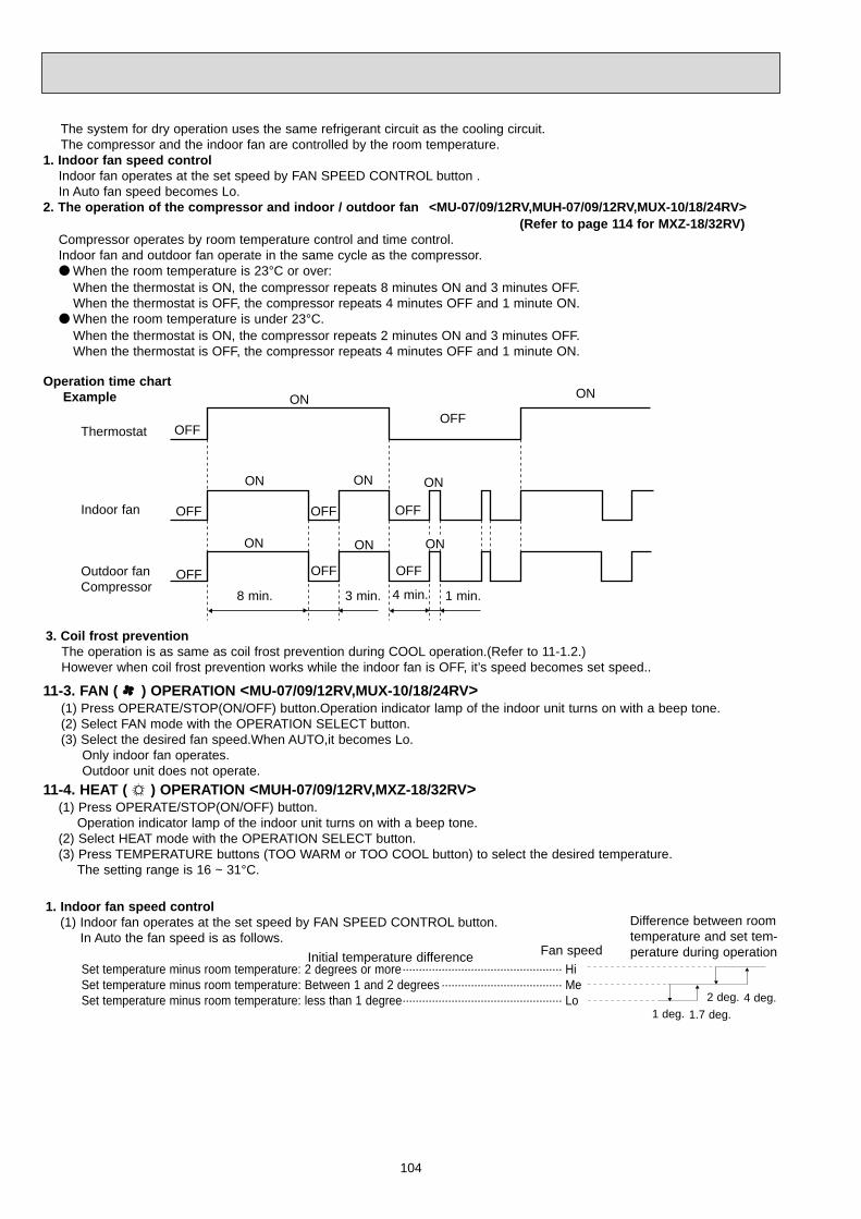
104
The system for dry operation uses the same refrigerant circuit as the cooling circuit.The compressor and the indoor fan are controlled by the room temperature.
1. Indoor fan speed controlIndoor fan operates at the set speed by FAN SPEED CONTROL button .In Auto fan speed becomes Lo.
2. The operation of the compressor and indoor / outdoor fan <MU-07/09/12RV,MUH-07/09/12RV,MUX-10/18/24RV>(Refer to page 114 for MXZ-18/32RV)
Compressor operates by room temperature control and time control.Indoor fan and outdoor fan operate in the same cycle as the compressor. When the room temperature is 23°C or over:
When the thermostat is ON, the compressor repeats 8 minutes ON and 3 minutes OFF.When the thermostat is OFF, the compressor repeats 4 minutes OFF and 1 minute ON.
When the room temperature is under 23°C.When the thermostat is ON, the compressor repeats 2 minutes ON and 3 minutes OFF.When the thermostat is OFF, the compressor repeats 4 minutes OFF and 1 minute ON.
Operation time chartExample
3. Coil frost preventionThe operation is as same as coil frost prevention during COOL operation.(Refer to 11-1.2.)However when coil frost prevention works while the indoor fan is OFF, it’s speed becomes set speed..
Thermostat
Indoor fan
Outdoor fan Compressor
ON
8 min. 1 min.4 min.3 min.
ON
OFF
OFF
OFF
OFFOFF
ONONON
ONONON
OFF
OFFOFF
11-3. FAN ( ) OPERATION <MU-07/09/12RV,MUX-10/18/24RV>(1) Press OPERATE/STOP(ON/OFF) button.Operation indicator lamp of the indoor unit turns on with a beep tone.(2) Select FAN mode with the OPERATION SELECT button.(3) Select the desired fan speed.When AUTO,it becomes Lo.
Only indoor fan operates.Outdoor unit does not operate.
11-4. HEAT ( ) OPERATION <MUH-07/09/12RV,MXZ-18/32RV>(1) Press OPERATE/STOP(ON/OFF) button.
Operation indicator lamp of the indoor unit turns on with a beep tone.(2) Select HEAT mode with the OPERATION SELECT button.(3) Press TEMPERATURE buttons (TOO WARM or TOO COOL button) to select the desired temperature.
The setting range is 16 ~ 31°C.
1. Indoor fan speed control (1) Indoor fan operates at the set speed by FAN SPEED CONTROL button.
In Auto the fan speed is as follows.
Set temperature minus room temperature: 2 degrees or more················································· HiSet temperature minus room temperature: Between 1 and 2 degrees ····································· MeSet temperature minus room temperature: less than 1 degree················································· Lo
1 deg. 1.7 deg.
2 deg. 4 deg.
Initial temperature difference Fan speed
Difference between roomtemperature and set tem-perature during operation
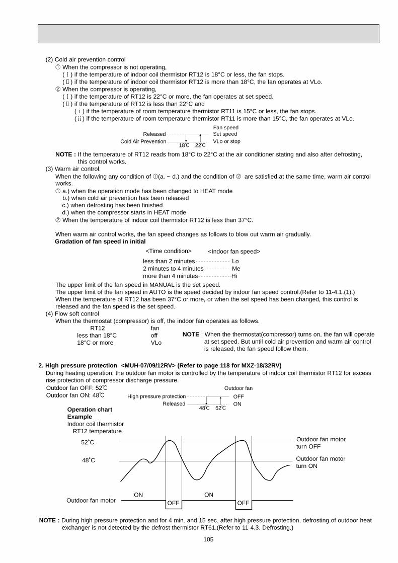
105
(2) Cold air prevention control1 When the compressor is not operating,
(1) if the temperature of indoor coil thermistor RT12 is 18°C or less, the fan stops.(2) if the temperature of indoor coil thermistor RT12 is more than 18°C, the fan operates at VLo.
2 When the compressor is operating,(1) if the temperature of RT12 is 22°C or more, the fan operates at set speed.(2) if the temperature of RT12 is less than 22°C and
(1) if the temperature of room temperature thermistor RT11 is 15°C or less, the fan stops.(2) if the temperature of room temperature thermistor RT11 is more than 15°C, the fan operates at VLo.
NOTE : If the temperature of RT12 reads from 18°C to 22°C at the air conditioner stating and also after defrosting, this control works.
(3) Warm air control.When the following any condition of 1(a. ~ d.) and the condition of 2 are satisfied at the same time, warm air controlworks.1 a.) when the operation mode has been changed to HEAT mode
b.) when cold air prevention has been releasedc.) when defrosting has been finished d.) when the compressor starts in HEAT mode
2 When the temperature of indoor coil thermistor RT12 is less than 37°C.
When warm air control works, the fan speed changes as follows to blow out warm air gradually.Gradation of fan speed in initial
The upper limit of the fan speed in MANUAL is the set speed.The upper limit of the fan speed in AUTO is the speed decided by indoor fan speed control.(Refer to 11-4.1.(1).)When the temperature of RT12 has been 37°C or more, or when the set speed has been changed, this control isreleased and the fan speed is the set speed.
(4) Flow soft controlWhen the thermostat (compressor) is off, the indoor fan operates as follows.
RT12 fanless than 18°C off18°C or more VLo
ReleasedCold Air Prevention
18: 22:
Fan speed Set speedVLo or stop
<Time condition> <Indoor fan speed>
less than 2 minutes Lo2 minutes to 4 minutes Memore than 4 minutes Hi
NOTE : When the thermostat(compressor) turns on, the fan will operateat set speed. But until cold air prevention and warm air controlis released, the fan speed follow them.
NOTE : During high pressure protection and for 4 min. and 15 sec. after high pressure protection, defrosting of outdoor heatexchanger is not detected by the defrost thermistor RT61.(Refer to 11-4.3. Defrosting.)
52˚C
48˚C
Outdoor fan motor
Outdoor fan motorturn OFF
Outdoor fan motorturn ON
ON ONOFF OFF
2. High pressure protection <MUH-07/09/12RV> (Refer to page 118 for MXZ-18/32RV)During heating operation, the outdoor fan motor is controlled by the temperature of indoor coil thermistor RT12 for excessrise protection of compressor discharge pressure.Outdoor fan OFF: 52:Outdoor fan ON: 48:
Operation chartExampleIndoor coil thermistor
RT12 temperature
High pressure protectionReleased
48: 52:
Outdoor fan
OFFON

106
3. Defrosting <MUH-07/09/12RV> (Refer to page 118 for MXZ-18/32RV)Defrosting of outdoor heat exchanger is controlled by DEICER P.C. board, with detection by the defrost thermistor RT61.(1) Starting conditions of defrost
When all conditions of a) ~ c) are satisfied, the defrosting operation starts.a) The compressor cumulative operation time exceeds 40 minutes without the defrosting operation working.b) RT61 reads - 3°C or less.c) After releasing the high pressure protection 4 minutes and 15 seconds have elapsed.
(2) Releasing conditions of defrostWhen the condition d) or e) is satisfied, the defrosting operation stops.d) RT61 reads 3.1°C or more.e) The defrosting time exceeds 10 minutes.
NOTE When the indoor coil thermistor RT12 reads above 18°C, indoor fan operates at VLo for 30 seconds. When the indoor coil thermistor RT12 reads 18°C or less, the indoor fan stops.
Defrost thermistor RT613.1: or more
-3: or less
Outdoor 52C contactor(Compressor)
X62(Reversing valve coil)
SR61Outdoor fan
Defrost counter
Indoor fan
IndoorHorizontal vane
ON
OFF
ON
OFF
ON
OFF
ON
OFF
ON
OFF
Horizontal
Set position
Max 10 min.
30 sec.
15 sec. 30 sec.
5 sec.
NOTE
VLo
Operation time chartExample

107
4. Reversing valve control <MUH-07/09/12RV>Heating · · · · · ONCooling · · · · · OFFDry · · · · · · · · OFF
When operation starts, the reversing valve reverses for 5 seconds right before start-up of the compressor.
ONOFF
ONOFF
ONOFF
ONOFF
ONOFF
ONOFF
Compressor
Reversing valve
Outdoor fan
(COOL / DRY) (HEAT)
5 sec. 5 sec.
Operation time chart
Mode
COOL mode of"I FEEL CONTROL"
DRY mode of"I FEEL CONTROL"
HEAT mode of"I FEEL CONTROL"
Initial room temperatureMUH&MXZ type
25: or more
23:or more, less than 25:
less than 23:
MU&MUX type
25: or more
more than13:, less than 25:
11-5. “I FEEL CONTROL” ( ) OPERATION(1) Press OPERATE/STOP(ON/OFF) butt.
Operation indicator lamp of the indoor unit turns on with abeep tone.
(2) Select “I FEEL CONTROL”( ) mode with the OPERA-TION SELECT button.
(3) The operation mode is determined by the initial roomtemperature at start-up of the operation, as shown on theright table.
Example
Previous operationCOOL mode of “I FEEL CONTROL”or COOL mode
Once the mode is fixed, the mode does not change by room temperature afterwards.
Under the ON-TIMER ( ) operation, mode is determined according to the room temperature at set time the opera-tion starts.
When the system is stopped on the remote controller and restarted within 2 hours in “I FEEL CONTROL” ( ) mode,the system operates in previous mode automatically regardless of the room temperature.
RestartCOOL mode of “I FEEL CONTROL”
Example
Previous operationCOOL mode of “I FEEL CONTROL”or COOL mode
When the system is restarted after 2 hours and more, the operation mode is determined by the room temperature atstart-up of the operation.
RestartCOOL or DRY orHEAT mode of “I FEELCONTROL” that deter-mined by room tem-perature at start-up ofthe operation.
Operation time chart
Operation time chart

108
Mode
COOL mode of"I FEEL CONTROL"
DRY mode of"I FEEL CONTROL"
HEAT mode of"I FEEL CONTROL"
Initial room temperatureInitial set temperature
26:
26: or more
25: or more, less than 26:
23: or more, less than25:
24:
Initial room temperatureminus 2:
Initial room temperatureminus 2:
1
more than 13:, less than 25:
26: or more
25: or more, less than 26:
less than 23:
MU & MUX type MUH & MXZ type
1 When the system is restarted with the remote controller, the system operates with the previous set temperature regard-less of the room temperature at restart.
(5) TEMPERATURES buttonsIn “I FEEL CONTROL” ( ) mode, set temperature is decided by the microprocessor based on the room temperature.In addition, set temperature can be controlled by TOO WARM or TOO COOL buttons when you feel too cool or toowarm.Each time the TOO WARM or TOO COOL button is pressed, the indoor unit receives the signal and emits a beeptone.
Fuzzy controlWhen the TOO COOL or TOO WARM button is pressed, the microprocessor changes the set temperature, consideringthe room temperature, the frequency of pressing TOO COOL or TOO WARM button and the user’s preference to heator cool. So this is called “Fuzzy control”, and works only in “I FEEL CONTROL” mode.In DRY mode of “I FEEL CONTROL”, the set temperature doesn’t change.
TOOCOOL … To raise the set temperature 1~2 degrees(°C)
TOOWARM … To lower the set temperature 1~2 degrees(°C)
(4) The initial set temperature is decided by the initial room temperature.
— COOL mode of “I FEEL CONTROL” —1. Indoor fan speed control
Indoor fan speed control is as same as COOL OPERATION.(11-1.1.)2. Coil frost prevention
Coil frost prevention is as same as COOL OPERATION.(11-1.2.)— DRY mode of “I FEEL CONTROL” —1. Indoor fan speed control
Indoor fan speed control is as same as DRY OPERATION.(11-2.1.)2. The operation of the compressor and indoor / outdoor fan
The operation of the compressor and indoor / outdoor fan is as same as DRY OPERATION.(8-2.2.)3. Coil frost prevention
Coil frost prevention is as same as DRY OPERATION.(11-2.3.)— HEAT mode of “I FEEL CONTROL” — <MUH-07/09/12RV,MXZ-18/32RV>1. Indoor fan speed control
Indoor fan speed control is as same as HEAT OPERATION.(11-4.1.)2. High pressure protection WW1
High pressure protection is as same as HEAT OPERATION.(11-4.2.)3. Defrosting WW1
Defrosting is as same as HEAT OPERATION.(11-4.3.)4. Reversing valve control WW1
Reversing valve control is as same as HEAT OPERATION.(11-4.4.)
WW1 Only MUH-07/09/12RV

109
1 In COOL and DRY operation
2 In HEAT operation <MUH-07/09/12RV>
Vane angle is fixed to Angle 1.
Vane angle is fixed to Angle 4.
11-6. FAN MOTOR CONTROL(1) Rotational frequency feedback control
The indoor fan motor is equipped with a rotational frequency sensor, and outputs signal to the microprocessor to feedbackthe rotational frequency. Comparing the current rotational frequency with the target rotational frequency (Hi,Me,Lo), themicroprocessor controls SR141and adjusts fan motor electric current to make the current rotational frequency close to thetarget rotational frequency. With this control, when the fan speed is switched, the rotational frequency changes smoothly.
(2) Fan motor lock-up protectionWhen the rotational frequency feedback signal is not output for 12 seconds, (or when the microprocessor cannot detectthe signal for 12 seconds) the fan motor is regarded locked-up. Then the electric current to the fan motor is shut off. 3 min-utes later, the electric current is applied to the fan motor again. During the fan motor lock-up, the Operation Indicator lampflashes on and off to show the fan motor abnormality. (See page 32.)
11-7. AUTO VANE OPERATION(1) Vane motor drive
These models are equipped with a stepping motor for the horizontal vane. The rotating direction, speed, and angle ofthe motor are controlled by pulse signals (approx. 12V) transmitted from indoor microprocessor.
(2) The horizontal vane angle and mode changes as follows by pressing the VANE CONTROL ( ) button.
(3) PositioningThe vane is once pressed to the vane stopper below to confirm the standard position and then set to the desired angle.Confirming of standard position is performed in case of follows.(a) When the OPERATE / STOP(ON / OFF) button is pressed.(b) When the vane control is changed from AUTO to MANUAL.(c) When the SWING is finished.(d) When the test run starts.(e) When the power supply turns ON.
(4) VANE AUTO ( ) modeIn VANE AUTO mode, the microprocessor automatically determines the vane angle to make the optimum room-temper-ature distribution.
2 In FAN operation <MU-07/09/12RV>
(5) Dew preventionDuring COOL or DRY operation at Vane Angle 4 or 5 when the cumulative operation time of compressor exceeds 1hour, the vane angle automatically changes to Angle 1 for dew prevention.
(6) SWING MODE ( )By selecting SWING mode with the VANE CONTROL button, the horizontal vane swings vertically.The remote controller
displays “ ”.SWING mode is cancelled when the VANE CONTROL button is pressed once again or in cool modeECONO COOL button is pressed.

110
(7) Cold air prevention in HEAT operation<MUH-07/09/12RV,MXZ-18/32RV>When any of the following conditions occurs in HEAT operation, the horizontal vane angle changes to Angle 1 automat-ically to prevent cold air blowing on users.① Compressor is not operating.➁ Defrosting is performed.➂ Indoor coil thermistor RT12 reads 24: or below.➃ Indoor coil thermistor RT12 temperature is raising from 24°C or below, but it does not exceed 28:.
Set position
Angle 1
Released
Cold air prevention24: 28:
Indoor coil thermistorRT12 temperature
NOTE : If the temperature of RT12 reads from 24°C to 28°C at the air conditioner stating , this control works.
11-8. TIMER OPERATION1. How to set the timer(1) Press OPERATE/STOP(ON/OFF) button to start the air conditioner.(2) Check that the current time is set correctly.NOTE : Timer operation will not work without setting the current time. Initially “AM0:00” blinks at the current time display
of TIME MONITOR, so set the current time correctly with CLOCK SET button.(3) Press ON or OFF TIMER buttons to select the operation.
“ ” button... AUTO START operation (ON timer)
“ ” button... AUTO STOP operation (OFF timer)
•ECONOmical operation (SET TEMPERATURE)When this operation is selected in MANUAL COOL mode, SET TEMPERATURE is automatically set 2°C higher thanthat in MANUAL COOL mode.By above SWING operation temperature that you feel can decrease by 2°C.So keeping comfort, energy can be saved.
Horizontal vane
Temperature of indoor coil thermistor RT12
more than 24°C
5
2
Downward blow time(sec.)
22°C to 24°C
21°C to 22°C
20°C to 21°C
18°C to 20°C
17°C to 18°C
15°C to 17°C
15°C or less
5
8
11
14
17
20
23
Upward(level) blow time (sec.)
20
17
14
11
8
223
(8) ECONO COOL ( ) operation (ECONOmical operation)When the ECONO COOL button is pressed in COOL mode, set temperature is automatically set 2°C higher than that inCOOL mode.Also the horizontal vane swings in various cycle according to the temperature of indoor heat exchanger(RT12).SWING operation makes you feel cooler than set temperature. So, even though the set temperature is higher than thatin COOL mode, the air conditioner can keep comfort. As a result, energy can be saved.
NOTE : ECONO COOL operation not work in COOL mode of “I FEEL CONTROL”.
SWING operationIn swing operation of ECONO COOL operation air flow is initially blew out upward(levelly).According to the temperature of indoor coil thermistor RT12 at starting of this operation, next downward blow time is decided. Then when the downward blow has been finished, next upward blow time is decided. For initial 10 min. the swing operation is performed in table G~H for quick cooling(but G : RT 12 is 24: or less). Also, after 10 min. when the difference of set temperature and room temperature is more than 2 degrees, the swingoperation is performed in table D~H for more cooling(but D: RT12 is 20: or less).The air conditioner repeats the swing operation in various cycle as follows.
A
H
G
F
E
D
C
B

111
EMERGENCY OPERATION switch
PROGRAM TIMER
(Example 1) The current time is 8:00 PM.The unit turns off at 11:00 PM, and on at 6:00 AM.
The OFF timer and ON timer can be used in combination. “ ” and “ ” display shows the order of the OFF timer and ON timer operation.
(Example 2) The current time is 11:00 AM.The unit turns on at 5:00 PM, and off at 9:00 PM.
NOTE : TIMER setting will be cancelled by power failure or breaker functioning.
11-9. EMERGENCY-TEST OPERATIONWhen the remote controller is missing, has failed or the batteries run down, use the EMERGENCY OPERATION switchon the front of the indoor unit for operation. The unit will start and the Operation Indicator lamp will light.The first 30 minutes of operation is the test run operation. This operation is for servicing. The indoor fan speed runs at Hinotch and the system is in continuous operation.(The thermostat is ON.)After 30 minutes of test run operation the system shifts to EMERGENCY COOL / HEAT<MUH-07/09/12RV,MXZ-18/32RV>MODE with a set temperature of 24°C.The fan speed shifts to Me notch.This operation continues until the EMERGENCY OPERATION switch is pressed once again(MU-07/09/12RV,.MUX-10/18/24RV)/ once or twice(MUH-07/09/12RV, MXZ-18/32RV) or the unit receives any signal from the remote controller.In case of latter normal operation will start.The coil frost prevention works even in this operation, and defrosting <MUH-07/09/12RV,MXZ-18/32RV> too.In the test run or emergency operation, the horizontal vane operates in VANE AUTO mode.NOTE : Do not press the EMERGENCY OPERATION switch during normal operation.
Press once <Cool>
Press again <Heat>
Press once again <Stop>
wHeat is available only in MUH-07/09/12RV,MXZ-
18/32RV.
2. Cancel
TIMER setting can be cancelled with the ON or OFF TIMER buttons. (“ ” or “ ”)
To cancel the ON timer, press the “ ” button.
To cancel the OFF timer, press the “ ” button.TIMER is cancelled and the display of set time disappears.
OPERATION INDICATOR lamp
(4) Press HR. and MIN. button to set the timer. Time setting is 10-minute units.
HR. and MIN. button will work when “ ” or “ ” mark is flashing.These marks disappear in 1 minute.After setting the ON timer, check that Operation indicator lamp of the indoor unit lights.
NOTE1 : Be sure to place the remote controller at the position where its signal can reach the air conditioner even duringTIMER operation, or the set time may deviate within the range of about 10 minutes.
NOTE2 : Reset the timer in the following cases, or the set time may deviate and other malfunctions may occur. A power failure occurs. The circuit breaker functions.

112
Compressorsecondarycurrent
Compressorprimarycurrent
Outdoor unit microprocessor
Drivecircuit
Compressor
TransistormoduleFin
temperaturethermistorRT63
Highpressureswitch
Suction temperature thermistor RT66
DischargetemperaturethermistorRT62
Accumulator
EvaporationtemperaturethermistorRT67
Capillarytube
Outdoorfan motor
DefrostthermistorRT61LEV B
LEV AIndoor unit A
Indoor unit B
Indoor unit A
Room AGas pipetemperaturethermistor
Room BGas pipetemperaturethermistor
Indoor unit B
Indoor unit A
Indoor unit B
<Refrigerant circuit>
<Electronic controls>
X64 X60X67
SSR
Reversing valve
11-10.1.System organization
MXZ-18RV - E1
11-10.INVERTER MULTI SYSTEM CONTROL

113
Powerfactor
Indoor unitmicroprocessor
SSR SSRSSRDrivecircuit
Transistormodule
Indoor UnitA
Indoor UnitD
Indoor UnitC
Indoor UnitB
Gas pipetemperaturethermistorRT66, 67, 68, 69
Reversingvalve
2-way-valve
Accumulator
Suctiontemperature
thermistorRT65
Crankcaseheater
Comp.
L.P.S
Inner thermostat
H.P.SDischargetemperaturethermistor RT61
Indoor UnitA Evaporation
temperaturethermistorRT64
Outdoorfan motor
x 61x 62x 63
DefrostthermistorRT62LEV1
LEV2
LEV3
LEV4
Indoor UnitB
Indoor UnitC
Indoor UnitD
Outdoor unit control microprocessor
Compressorprimarycurrent
Compressorsecondarycurrent
Fin temperaturethermistor RT63
MXZ-32RV - E1

114
Linear expansion valve (LEV) is controlled by "Thermostat ON" commands given from each unit.
For the differential start-up, the LEV is controlled at 52 pulse for the first 15 minutes after compressor stop.
There are 10 levels specified for standard LEV opening depending on the compressor operational frequency.Based on these standard valves, the LEV opening is modified according to the suction super heat, discharge tem-perature, and gas pipe temperature.<LEV opening>
<Standard LEV opening by capacity code>
Standard LEV opening
30
Level 10Level 09Level 08Level 07Level 06Level 05Level 04Level 03Level 02Level 01
40 50 60 70 80 90 100 110 120
Hysteresis width=5Hz
< COMP Hz >
Non-opening indoor unit
Outdoor unit ON (Indoor unit ON) : 5 pulseOutdoor unit OFF (Indoor unit OFF or Thermostat OFF) : Before shutdown
Refer to the standard LEV opening as shown below. From the initial valve, the LEV opening is controlled according to suction superheat and the discharge temperature.
Refer to the standard LEV opening as shown below. From the initial valve, the LEV opening is controlled according to the suction superheat and the discharge temperature.
Thermostat ON in HEAT mode
LEV opening
Thermostat ON in DRY mode
Thermostat OFF in COOL or DRY mode
Thermostat OFF in HEAT mode
All indoor units OFF 52 500 pulse
Indoor unit status
COOL : 5 pulseHEAT : 59 pulse
COOL : 5 pulseHEAT : 49 pulse
Refer to the standard LEV opening as shown below.
Thermostat ON in COOL mode
Before shutdown 350 pulse
Outdoor unit ON (Indoor unit ON) : 5 pulseOutdoor unit OFF (Indoor unit OFF or Thermostat OFF) : 52 500 pulse
Outdoor unit ON (Indoor unit ON) : 49 pulseOutdoor unit OFF (Indoor unit OFF or Thermostat OFF) : Before shutdown
Outdoor unit ON (Indoor unit ON) : 5 pulseOutdoor unit OFF (Indoor unit OFF or Thermostat OFF) : 52 500 pulse
MXZ-18RV MXZ-32RV
Capacity class
Level 01Level 02Level 03Level 04Level 05Level 06Level 07Level 08Level 09Level 10
07,09100/70100/70100/90100/110100/130110/150120/170130/190140/210150/230
MXZ-32RV-E112,13
140/90140/90140/110140/130140/150150/170160/190170/210180/230190/250
12255/90255/90255/90255/90255/90255/100255/110255/120255/130255/140
07,09255/70255/70255/70255/70255/70255/80255/90255/100255/110255/120
18160/100160/100160/120160/140160/160170/180180/200190/220200/240210/260
MXZ-18RV-E1
11-10.2.LEV control
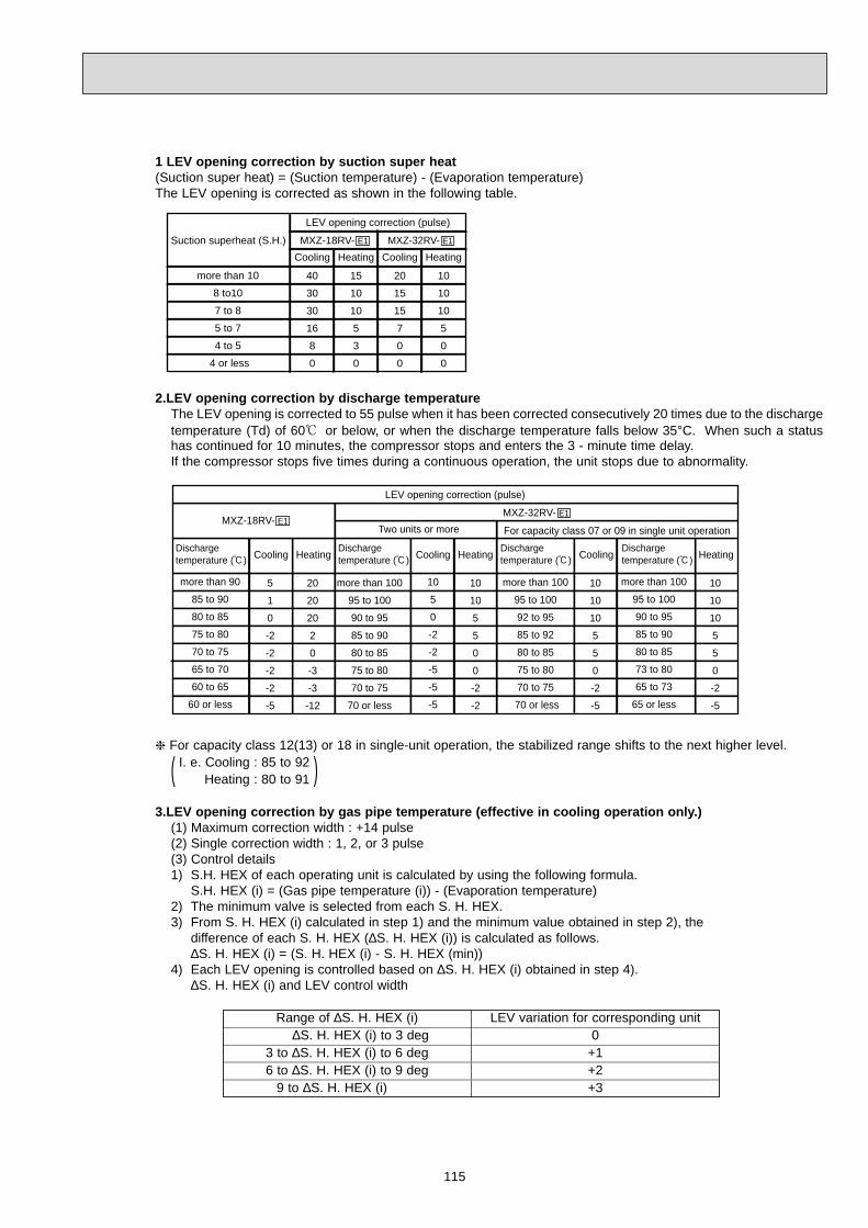
115
1 LEV opening correction by suction super heat(Suction super heat) = (Suction temperature) - (Evaporation temperature)The LEV opening is corrected as shown in the following table.
2.LEV opening correction by discharge temperature The LEV opening is corrected to 55 pulse when it has been corrected consecutively 20 times due to the dischargetemperature (Td) of 60; or below, or when the discharge temperature falls below 35°C. When such a statushas continued for 10 minutes, the compressor stops and enters the 3 - minute time delay.If the compressor stops five times during a continuous operation, the unit stops due to abnormality.
For capacity class 12(13) or 18 in single-unit operation, the stabilized range shifts to the next higher level.I. e. Cooling : 85 to 92( Heating : 80 to 91 )
3.LEV opening correction by gas pipe temperature (effective in cooling operation only.)(1) Maximum correction width : +14 pulse(2) Single correction width : 1, 2, or 3 pulse(3) Control details1) S.H. HEX of each operating unit is calculated by using the following formula.
S.H. HEX (i) = (Gas pipe temperature (i)) - (Evaporation temperature)2) The minimum valve is selected from each S. H. HEX.3) From S. H. HEX (i) calculated in step 1) and the minimum value obtained in step 2), the
difference of each S. H. HEX (∆S. H. HEX (i)) is calculated as follows.∆S. H. HEX (i) = (S. H. HEX (i) - S. H. HEX (min))
4) Each LEV opening is controlled based on ∆S. H. HEX (i) obtained in step 4).∆S. H. HEX (i) and LEV control width
Range of ∆S. H. HEX (i) LEV variation for corresponding unit∆S. H. HEX (i) to 3 deg 0
3 to ∆S. H. HEX (i) to 6 deg +16 to ∆S. H. HEX (i) to 9 deg +2
9 to ∆S. H. HEX (i) +3
Suction superheat (S.H.)
Cooling CoolingHeating Heating
MXZ-32RV- E1MXZ-18RV- E1
LEV opening correction (pulse)
more than 10
8 to10
7 to 8
5 to 7
4 to 5
4 or less
40
30
30
16
8
0
15
10
10
5
3
0
20
15
15
7
0
0
10
10
10
5
0
0
Discharge temperature (:) Cooling CoolingCooling HeatingHeating Heating
MXZ-32RV- E1
LEV opening correction (pulse)
more than 100
95 to 100
90 to 95
85 to 90
80 to 85
75 to 80
70 to 75
70 or less
10
5
0
-2
-2
-5
-5
-5
10
10
5
5
0
0
-2
-2
10
10
10
5
5
0
-2
-5
10
10
10
5
5
0
-2
-5
5
1
0
-2
-2
-2
-2
-5
20
20
20
2
0
-3
-3
-12
MXZ-18RV- E1
more than 100
95 to 100
92 to 95
85 to 92
80 to 85
75 to 80
70 to 75
70 or less
more than 100
95 to 100
90 to 95
85 to 90
80 to 85
73 to 80
65 to 73
65 or less
more than 90
85 to 90
80 to 85
75 to 80
70 to 75
65 to 70
60 to 65
60 or less
Discharge temperature (:)
Discharge temperature (:)
Discharge temperature (:)
Two units or more For capacity class 07 or 09 in single unit operation

116
The outdoor fan turns ON according to "Compressor ON" commands given from each indoor unit.
The outdoor fan is controlled at High speed for the first 10 secondsafter start-up. In addition, the outdoor fan speed temporarilychanges to High during the compressor and inverter protection.
1.Compressor shell overheat protectionWhen a single unit is operating in a system with the LEV fully open and the discharge temperature at 95; or above, theoutdoor fan speed changes to High. It is released when the number of operating indoor units has changed, the opera-tion mode has changed, or the power has turned OFF.
2.Inverter overheat protectionWhen the fin temperature thermistor detects 88; or above, the indoor fan speed changed to High. It is released whenthe compressor has turned OFF.
3.After defrosting during heating operation, the outdoor fan speed shifts to the next higher level.I. e. Low to Me( Me to High )
The compressor operational frequency and the LEV opening are controlled depending on the number of operating indoorunits.1.Compressor operational frequency
• The variable range of compressor operational frequency changes according to the operation signal (capacity code andtemperature difference) given from the operating indoor unit (s).When the number of operating indoor units is reduced during heating operation, the operational frequency will decreaseby 20 Hz in one minute. After that, the operational frequency will return to the variable status.
2.LEV opening• The LEV opening varies according to the operation signal given from the operating indoor unit (s).
When the number of operating indoor units is reduced during heating operation, the LEV opening will be fixed to thecurrent valve for one minute. After that, the LEV opening will return to the variable status.
(1) When a single indoor unit is operating, the system operates in the mode as selected by that indoor unit.(2) When two indoor units are operating in the same mode, the system operates in that mode.(3) Simultaneous COOL and HEAR operation is unavailable within a system. The indoor unit activated earlier has the
priority to decide the operation mode of the system. The other unit enters the standby status when it receives the order to operate in a different mode. To operate these units in the same mode from such a status, reset both units to the same operation mode, turned them off, and then turn them back on.
(4) Simultaneous COOL and DRY operation is available within a system. In this case, the outdoor unit operates in the COOL mode. (The outdoor unit operates in the DRY mode only when all the indoor units are operating in the DRYmode.)
CoolingHeating
12345678910
Totalcapacity code
Oneunit
Low
Twounit
Low
Threeunit
Me
Fourunit
Number 05operating
indoorunit
MeMe
MXZ-32RV- E1
MXZ-18RV- E1
Oneunit
Twounit
Number of operating indoor unit
HiHi
HiHi
Indoor unitcapacity class
Capacity code
07/09 112(13) 3
18 4
11-10.3.Control by the number of operating indoor unit
11-10.4.Selection of operation mode
11-10.5.Outdoor fan control

117
Compressor operational frequency range(1) COOLING
(2) HEATING
Number ofoperating unit
Minimum DRY modeMaximum RatingTotal capacitycode
MXZ-32RV- E1
MXZ-18RV- E1
1
2
34
12342345678--
30
35
4040
52
73
90
110
120120
40
58
7575
40
52
5875
105
102102
Number ofoperating unit
Minimum DRY modeMaximum Rating
1
2
07 or 09
1207+12
or09+09
34
34
58
66
80
43
43
43
58
76
Indoor unitcapacity class
11-10.6.Operational frequency range
Number ofoperating unit
Minimum DEFROST mode
Maximum RatingTotal capacitycode
MXZ-32RV- E1
MXZ-18RV- E1
1
2
34
12342345678--
30
40
4848
58
73
95
115
120120
105
45
65
5875
107
112105
Number ofoperating unit
Minimum DEFROST mode
Maximum RatingIndoor unitcapacity class
1
2
34
34
62
66
82
84
70
86
70
86
07 or 09
12
09+09
07+12

118
<Conditions to start defrosting>The system starts defrosting when it satisfies both of the following conditions :① The defrost thermistor detects -3°C or below.➁ Defrost interval (I. e. the accumulated compressor operation time) counted by the controller board has reached the
prescribed value.<Details of defrosting>
① The compressor stops for 32.5 seconds and the indoor fan turns OFF.➁ The reversing value reverses and the compressor runs at the defrosting frequency.③ After the defrosting termination conditions are satisfied, the compressor stops for 32.5 seconds and the reversing valve
reverses. This is the end of defrosting.<Conditions to terminate defrosting>
The system terminates defrosting when it satisfies, either of the following conditions :① The defrost thermistor detects +10°C or above.➁ Defrosting time has reached 10 minutes.
(1) High pressure protection in heating• The operational frequency, 2 - way valve (only MXZ-32RV), and outdoor fan motor are controlled according to the
indoor coil temperature.When it rises to nearly 50°C, the operational frequency will be fixed to the value at the moment and the outdoor fanspeed will change to low.When it rises to nearly 53°C, the operational frequency will be reduced by 4 Hz from the current value and the 2 - wayvalve will open.
(2) High pressure protection by high pressure switch (H.P.S : MXZ-18RV , 63H1 : MXZ-32RV)• The operational frequency, 2 - way valve (only MXZ-32RV), and outdoor fan motor are controlled by the high pressure
switch to protect excessive high pressure.<Condition to active the protection>The high pressure protection starts when the high pressure switch turns ON, that is the discharge pipe pressure rises to
2.75 MPa (28 kg/cm2) or above.<Protection details>a) In COOL or DRY mode
• The 2 - way valve opens.• The compressor operational frequency decreases at a rate of 10 Hz/minute.
b) In HEAT mode• The 2 - way valve opens.• The compressor operational frequency decreases at a rate of 10 Hz/minute.• The outdoor fan runs at the Low speed.
<Condition to release the protection>The protection is released when the high pressure switch turns OFF, that is, the discharge pipe pressure falls to2.4±0.15MPa (24.5 ± 1.5 kg/cm2) or below.
(3) Low pressure protection by low pressure switch (only MXZ-32RV)• The compressor ON/OFF, operational frequency, 2 - way valve, and LEV opening are controlled by the low pressure
switch to protect excessive low pressure.<Condition to active the protection>The protection starts when the low pressure switch turns ON, that is, the suction pipe pressure falls to 0.05 ± 0.04MPa(0.5 ± 0.4 kg/cm2) or below.<Protect details>• The 2 - way valve opens.• The compressor operational frequency decreases at a rate of 10 Hz/minute.• The LEV opens at a rate of 20 pulse/minute. When such a status has continued for five minutes, the compressor will
turn OFF and the error content will be displayed.<Condition to release the protection>The protection is released when the low pressure switch turns OFF, that is, the suction pipe pressure falls to
0.15±0.04MPa (1.5 ± 0.4 kg/cm2).(4) High pressure protection by high pressure switch (63H2 : MXZ-32RV )
• The compressor is turned OFF by the high pressure switch to prevent excessive high pressure.<Condition details>The compressor stops operation.<Condition to release the protection>• The compressor is turned OFF once and turned ON again.
+ 0.5- 1.0
+ 0.05- 0.1
11-10.7.Defrosting in heating
11-10.8.High and low pressure protection

119
• The compressor ON/OFF and operational frequency are controlled according to the discharge temperature.(1) Compressor ON/OFF
The compressor turns OFF when the discharge temperature thermistor rises above 120°C. The compressor turns ONwhen the discharge temperature thermistor falls below 80°C.
(2) Compressor operational frequencyWhen the estimated discharge temperature is high than 120°C, the compressor operational frequency will decrease by8 Hz from the current operational frequency. When the estimated discharge temperature is over 115°C to 120°C inclu-sive, the compressor operational frequency will decrease by 4 Hz from the current operational frequency.When the estimated discharge temperature is over 107°C to 115°C inclusive, the compressor operational frequency willbe fixed to the current operational frequency.
<Conditions to active refrigerant recovery>The system activates refrigerant recovery when it satisfies all the following conditions : • One or more indoor unit are standstill during heating operation. (It does not include the "Thermostat OFF" starts.)• The discharge temperature rises to 107°C or above.• Sixty minutes or more have passed since the operation start-up or the last refrigerant recovery.
<Control details>• The LEV opening is controlled at 80 pulse for the non-operating indoor unit(s).
<Conditions to discontinue refrigerant recovery>The system discontinues refrigerant recovery when it satisfies either of the following conditions. Then the LEV openingis controlled to 59(MXZ-32RV) / 49(MXZ-18RV) pulse.• Sixty seconds have passed since the start-up of refrigerant recovery.• The discharge temperature falls to 90;(MXZ-32RV) / 100;(MXZ-18RV) or below.
Relation between major sensors and actuators.
Discharge tempera-ture thermistor
Purpose
Protection
Defrosting
Control
Control
Control
Protection
Protection
Protection
Control
Compressor LEV Outdoor fan motor
Reversingvalve
2-way valve(MXZ-32RV)
Sensor
Defrost thermistor
Suction temperaturethermistor
Fin temperaturethermistor
Capacity code
Low pressure switch(MXZ-32RV)
Evaporation tempe-rature thermistor
Gas pipe tempera-ture thermistor
High pressureswitch
Actuator
11-10.9.Discharge temperature protection
11-10.10.Refrigerant recovery in heating
11-10.11.Sensors and actuators

120
SERVICE FUNCTIONS12
12-1. COMPULSORY DEFROSTING MODE FOR SERVICE<MUH-07/09/12RV>By short circuit of the connector JP607 and R853 on the outdoor deicer P.C. board, defrosting mode can be accom-plished regardless of the defrost interval restriction. (See page 143.)Defrost thermistor RT61 must read below -3°C.
12-2. CHANGE IN DEFROST SETTING<MUH-07/09/12RV>W MXZ-18/32RV is not equipped with this function.<JPC> when the JPC wire of the deicer P.C. board is cut, the defrost interval time will be changed. (See page 143.)<JPE> when the JPE wire of the deicer P.C. board is cut, the defrost temperature will be changed. (See page 143.)
12-4. P.C. BOARD MODIFICATION FOR INDIVIDUAL OPERATIONA maximum of 4 indoor units with wireless remote controllers can be used in a room.In this case, to operate each indoor unit individually by each remote controller, P.C. boards of remote controller must bemodified according to the number of the indoor unit.
MUH-07RV -
MUH-09RV -
MUH-12RV -
Jumper wire
JPC
JPE
MODEL Change point
Defrost interval time changes from 40 minutes to 15 minutes
Deforst start temperature changes from -3: to 0: Deforst finish temperature changes from 3.1: to 10.1:.
E1
E1
E1
12-3. TIMER SHORT MODEFor service, set time can be shortened by short circuit of JPG and JPS the electronic control P.C. board.The time will be shortened as follows.3-minutes delay : 3-minutes 3-seconds.AUTO START : 1 hour 1-minuteAUTO STOP : 1 hour 1-minute Short the connector during the timer mode.
How to modify the remote controller P.C. boardRemove batteries before modification.The board has a print as shown below :
The P.C.board has the print “J1” and “J2”.Jumper wires are mounted to each “J1” and “J2”.Cut J1 and J2 according to thenumber of indoor unit as shown in Table 1.After modification,push the reset button.
NOTE : For remodelling, take outthe batteries at first.After finish remodelling, putback the batteries thenpush the RESET button.
No. 1 unit
No. 2 unit
No. 3 unit
No. 4 unit
1 unit operation
No modification
–
–
–
2 units operation
Same as at left
Cut J1
–
–
3 units operation
Same as at left
Same as at left
Cut J2
–
4 units operation
Same as at left
Same as at left
Same as at left
Cut both J1 and J2
Table.1
NOTE : At power supply failure or installation, indoor unit deletes the memory about remote controller. When the power supplyis turned on and indoor unit receives the first signals from the remote controller, the remote controller number is desig-nated as the indoor unit number. Therefore at and after the second time indoor unit accepts the remote controller ofthe initial setting number.At setting - error, turn the power supply off to cancel the individual operation and then turn the power supply on to restart the setting.
MUH-07RV -MUH-09RV -MUH-12RV - E1
E1
E1MU-07RV -MU-09RV -MU-12RV - E1
E1
E1MSC-07RV -MSC-09RV -MSC-12RV - E1
E1
E1 MUX-10RV -MUX-18RV -MUX-24RV - E1
E1
E1 MXZ-18RV -MXZ-32RV - E1
E1

121
1. MU TYPE / MUH TYPE SWITCH OVER The indoor units for MU type and MUH type are common specifications. Set switch according to thetype of outdoor unit.The units are set for MUH typewhen they are shipped from the factory.
How to set “AUTO RESTART FUNCTION”! Turn off the main power for the unit. @ Pull out the electronic control P.C. board, and change switch(SW2-1) on the indoor electronic control P.C. board as
follow figures.
1 2C
111
CN201
C11
CN211
IC15
2
CN
151
SW1
CN
112 C
N12
1
IC101
CN
111
CN202
TAB12
SW2
SW2
INDOOR ELECTRIC CONTROL P.C. BOARD
1 2
SW21 2
SW2-1 sets the AUTO RESTART FUNCTION ON / OFF.SW2-2 switches over the MU type/ MUH type. When the units are shipped from the factory, SW2 is as follows. SW2-1: AUTO RESTART FUNCTION OFF SW2-2: MUH type
Operation! If the main power (220/240V AC) has been cut, the operation settings remain.@ After the power is restored, the unit restarts automatically according to the memory.(However, it takes at least 3 min-
utes for the compressor to start running.)NOTE•The operation settings are memorized when 10 seconds have passed after the remote controller was operated.•If main power is cut while AUTO START/STOP timer is active ,the timer setting is cancelled.•If the unit has been off with the remote controller before power failure, the auto restart function does not works as the power button of the remote controller is off.•To prevent breaker off due to the rush of starting current, systematize other home appliance not to turn on at the same time.•When some air conditioners are connected to the same supply system, if they are operated before power failure, the starting current of all the compressors may flow simultaneously at restart.Therefore, the special counter-measures are required to prevent the main voltage-drop or the rush of the starting current by adding to the system that allows the units to start one by one.
12-5. MU TYPE / MUH TYPE SWITCH OVER AND AUTO RESTART FUNCTION
2. AUTO RESTART FUNCTIONWhen the indoor unit is controlled with the remote controller, the operation mode, set temperature, and the fan speed are memorized by the indoor electronic control P.C.board. The “AUTO RESTART FUNCTION” sets to work the momentpower has restored after power failure.Then, the unit will restart automatically. However if the unit is operated in “I FEELCONTROL” mode before power failure, the operation is not memorized. In “I FEEL CONTROL” mode, the operation isdecided by the initial room temperature. “AUTO RESTART FUNCTION” is OFF when the units are shipped from thefactory.
1 2
SW21 2
1 2
SW21 2
Outdoor unit MUH& MXZ type
Set 2 switch downside.
Outdoor unit MU & MUX type
Set 2 switch upside.
NOTE:•If the indoor-outdoor connecting wire is incorrectly connected on the terminal block, the unit does not operate normally.
•If a ground is incorrect, it may cause an electric shock.
How to switch over MU TYPE / MUH TYPE! Turn off the main power for the unit.@ Pull out the electronic control P.C. board, and change
switch(SW2-2) on the indoor electronic control P.C.board according to the type of outdoor unit as follow-ing figures.
1 2
SW21 2
1 2
SW21 2
AUTO RESTART FUNCTION OFF
Set 1 switch upside.
AUTO RESTART FUNCTION ON
Set 1 switch downside.

122
13 TROUBLESHOOTING
3. Troubleshooting procedure1) First, check if the OPERATION INDICATOR lamp on the indoor unit is flashing on and off to indicate an abnormality.
To make sure, check how many times the abnormality indication is flashing on and off before starting service work.2) If the electronic control P.C. board is supposed to be defective, check the copper foil pattern for disconnection and the
components for bursting and discoloration.3) When troubleshooting, refer to the flow chart on page 123, 124 and the check table on page 125~127.
4. How to replace batteriesWeak batteries may cause the remote controller malfunction.In this case, the remote controller can not be repaired only by the battery replacement. To operate the remote controllernormally, discharge the remote controller in the following order.This remote controller has the RESET button. After refilling new batteries, press the RESET button with tip end of ballpoint pen or the like, and then use the remote controller.
Lead wiring Housing point
MUH-07RV -MUH-09RV -MUH-12RV - E1
E1
E1
RESET button
MSC-07RV -MSC-09RV -MSC-12RV - E1
E1
E1 MU-07RV -MU-09RV -MU-12RV - E1
E1
E1
13-1. Cautions on troubleshooting1. Before troubleshooting, check the following:
1) Check the power supply voltage.2) Check the indoor/outdoor connecting wire for mis-wiring.
2. Take care the following during servicing.1) Before servicing the air conditioner, be sure to first turn off the remote controller to stop the unit, and then after con-
firming the horizontal vane is closed, turn off the breaker and / or disconnect the power plug.2) Be sure to unplug the power cord before removing the front panel, the cabinet, the top panel, and the electronic con-
trol P.C. board.3) When removing the electronic control P.C. board, hold the edge of the board with care NOT to apply stress on the
components.4) When connecting or disconnecting the connectors, hold the housing of the connector. DO NOT pull the lead wires.
MXZ-18RV -MXZ-32RV - E1
E1

123
13-2. Instruction of troubleshooting<MU-07/09/12RV,MUH-07/09/12RV,MUX-10/18/24RV> (Refer to page 124 for MXZ-18/32RV)
Indoor unit oper-ates. Outdoor unitdoesn’t operate.
Outdoor unitoperates inonly TestRun opera-tion.
Outdoor unitdoesn’t oper-ate even inTest Runoperation.
Check roomtemperaturethermistor.
Refer to“Check ofoutdoor unit”on page 133and 134.
Indoor unit doesn’treceive the signalfrom remote controller.
Refer to “Check of remotecontroller andreceiver P.C. board”on page 132.
OPERATION INDICATORlamp on the indoor unit isflashing on and off.
Indoor unit doesn’treceive the signal fromremote controller.Also, OPERATION INDI-CATOR lamp doesn’tlight, when the EMER-GENCY OPERATIONswitch is pressed.
Refer to “Check ofindoor electronic controlP.C. board” on page 133.
Cause:indoor/outdoor unitconnectingTrouble of mis-wiringTrouble of the serial signal
Cause:Indoor unit2-time-Room tempera-
ture/Indoor coilthermistor trouble
3-time-Indoor fan motortrouble
Refer to “How to checkmis-wiring and signal error(when outdoor unitdoesn’t work)”on page 135. 1
6-time flash
2.5-second OFF
Cause:outdoor unit6-time-Check the defrost
thermistorE
D
B
Check room temperaturethermistor. Refer to“Testpoint diagram and volt-age” on page 142.
Refer to“Check of indoorfan motor” onpage 132.
Check indoor coilthermistor. Referto“Test point dia-gram and voltage”on page 142.
1<The case of the trouble of the serial signal>When the power is turned off and then turned on again, the indi-cation shows “the trouble of mis-wiring.”
2-time flash
2.5-second OFF
3-time flash
2.5-second OFF
Start
1-time flash
C
A
(

Indoor unit dose not operate.(different modes )• When you try to operate two or more indoor units with one outdoor unit simultaneously, one for the cooling and the other
for heating, the operation mode of the indoor unit that operates earlier is selected. The other indoor units that will start theoperation later cannot operate, indicating as shown in the figure below. In this case, please set all the indoor units to thesame operation mode.
• When indoor units starts the operation while the defrosting of outdoor unit is being done, it takes a few minutes (max.10minutes) to blow out the warm air.
• In the heating operation, though indoor unit that dose not operate may get warm or the sound of refrigerant flowing maybe heard, they are not malfunction. The reason is that the refrigerant continuously flows into it.
124
<MXZ-18RV,MXZ32RV>
The other cases
OPERATION INDICATOR
Lighting Frashing
Indoor unit operates.Outdoor unit dosen'toperate.
OPERATION INDICATORlamp on the indoor unit is flashing on and off.
Operation start
Outdoor unitoperates inonly TestRun opera-tion.
NOTE1:In case of serial signalerror, the mis-wiringindication will apper byturning the power off andturning it back on.
NOTE2:Enclosed by thebroken line are the indoorunit related parts.
InverterCompressor
G to KCompressorSee page 136,137.
Check indoor coil thermistor. Referto "Test point dia-gram and voltageon page 142.
Refer to T "Mis-wiring or mis-piping" on page 140,141.
Indoor unit dosen't receive the signal from remote controller.Also, OPERATION INDICATOR lamp doesn'tlight, when the EMERGENCY OPERATION switch is pressed.
1-time flash
2-time flash
2.5 second OFF
2.5 second OFF
3-time flash
G to KTransistor moduleSee page 136,137.
L OutdoorthermistorSee page 138.
M Reversingvalve coil.See page 138.
• High pressure switch
OnlyMXZ-32RV• Low pressure switch• Compressor thermostat
Linearexpansionvalve
N Outdoor fanmotor.See page 139.
P Power supplySee page 139.
Outdoor controll P. C. board
Indoor unit doesn'treceive the signal from remote controller.
Outdoor unitdoesn't oper-ates even inTest Run operation.
Check room temperaturethemistor.
Refer to "F Simplecheck methods for inverter/compressor" on page 136.
Outdoor unitoperates inonly TestRun opera-tion
Cause:indoor/outdoor unitconnectingTrouble of mis-wiringTrouble of the serial signal
Cause:indoor unit2-time-Room temperture/
indoor coil thermi-stor trouble
3-time-Indoor fan motortrouble
Cause:Outdoor unit5-time-Power system abnormality6-time-Thermistor abnormality7-time-Control system error
Refer to c "Check of indoor electronic controll P.C. board"on page 133.
Refer to A "Check of indoor fan motor" on page 132.
Check room tempe-rature thermistor. Refer to "Test point diagram and voltageon page 142.
6-time flash
2.5 second OFF
5-time flash
2.5 second OFF
7-time flash
2.5 second OFF

125
13-3. troubleshooting check table <INDOOR UNIT>
lighting
not lightingOperation Indicator
Before taking measures, make sure that the symptom reappears, for accurate troubleshooting.Self check table
NO.
1
2
3
4
Abnormalpoint
Mis-wiring
Serialsignal
Indoor coilthermistor
Roomtempera-ture ther-mistor
Indoor fanmotor
Defrostthermistor
Indication
0.5-second ON
0.5-second OFF
1-time flash
2.5-second OFF
2-time flash
2.5-second OFF
3-time flash
2.5-second OFF
6-time flash
2.5-second OFF
Symptom
Outdoor unitdoes not run.
Outdoor unitdoes not run.
Indoor fan motorrepeats 12 sec-onds ON and 3minutes OFF.When the indoorfan motorbreaks, the fankeeps stopping.
Outdoor unitdoes not run
Detect method
When serial signal stops for 4to 5 seconds after 1st on of52C relay by POWER turningon.
When serial signal from out-door unit stops for 4 to 5 sec-onds.
Detect Indoor coil/room tem-perature thermistor short oropen circuit every 8 secondsduring operation.
When rotational frequencyfeedback pulse signal is notemit during 12-second indoorfan operation.
When the defrost thermistorshorts or opens after the com-pressor start-up.
Check point
Check switch SW2-2.(MU type or MUHtype)
Check wiring (visual check and conductiv-ity check).
Check indoor electronic controlP.C.board.
Check outdoor DEICER P.C. board. Check electrical parts.
Check resistance of thermistor. Reconnect connector. Check indoor electronic control P.C.board.
Disconnect connector CN211 and thencheck connector CN121 - to makesure rotational frequency feedback signalof 1.5V or over exists.
Check indoor electronic control P.C.board.
Check indoor fan motor. Reconnect connector.
Check outdoor DEICER P.C. board.(MUH) Check outdoor control P.C. board. (MXZ) Check resistance of thermistor. Reconnect connector.
2 3
5
Out doorcontrolsystemerror
7-time flash
2.5-second OFF
Outdoor unitdoes not run
Check outdoor control P.C. board.
Outdoorpower system
5-time flash
2.5-second OFF
Out doorrefriger-antsystemerror
7
6
Outdoor unitdoes not run
When compressor hasstopped due to over currentprotection or start-up failureprotection 3 times in a rowwithin 1 min. after start-up.
Check inverter and compressor.
10-time flash
2.5-second OFF
Outdoor unitdoes not run
Amount of gas. Outdoor control P. C. board. Contact of LEV board connectors.
When the compressor opera-tion has been interrupted byLEV protection continuously 5times, the compressor stopsoperation.

126
Outdoor power system abnor-mality
When the compressor operation has been interrupted by overcurrentprotection continuously three times within 1 minute after start-up, thecompressor stops operation.
• Inverter output• Compressor
Display Detecting method Detecting method Check points
Symptom Outdoor unit does not operate.
(1) Troubleshooting tableNote . LED indicates "00" in the normal status.
7-segment LED display Error modeNormal
Outdoor refrigerant systemabnormality (LEV abnormality)
When the compressor operation has been interrupted by LEV protectioncontinuously five times, the compressor stops operation.
• Amount of gas• Outdoor control P.C. board• Contact of LEV board connectors
Outdoor controller boardabnormality
When the nonvolatile memory data cannot be read properly on the out-door controller board
• Outdoor control P.C. board
<Only MXZ-32RV>Compressor temperatureabnormality
When the compressor has remained OFF for continuous thirty minutesby inner thermostat function
• Outdoor air cycle• Amount of gas• Outdoor fan motor• Outdoor heat exchanger
(dust adherence)
Indoor unit and LEV abnor-mality
When the drain abnormality is detected in the indoor unit and the indoormain coil temperature is too low, or when any abnormality is detected inthe components of indoor unit
• Check the abnormality indication on theindoor unit.
• LEV
Suction temperature thermis-tor abnormality
The compressor stops when a short or open circuit occurs in the suctiontemperature thermistor during compressor running.
• Check the characteristic of the suctiontemperature thermistor. Refer to LL onpage 138.
• Check the contact of P. C. board con-nectors.
Display Detecting method Detecting method Check points
Symptom Outdoor unit stops and restarts every 3 minutes.
Evaporation temperature ther-mistor abnormality
The compressor stops when a short or open circuit occurs in the evap-oration temperature thermistor during compressor running.
• Check the characteristic of the evapora-tion temperature thermistor. Refer to LLon page 138.
• Check the contact of P. C. board con-nectors.
Discharge temperature ther-mistor abnormality
The compressor stops when a short or open circuit occurs in the dis-charge temperature thermistor during compressor running.
• Check the characteristic of the dischargetemperature thermistor. Refer to LL onpage 138.
• Check the contact of P. C. board con-nectors.
Fin temperature thermistorabnormality
The compressor stops when a short or open circuit occurs in the fin tem-perature thermistor during compressor running.
• Check the characteristic of the fin temper-ature thermistor. Refer to LL on page138.
• Check the contact of P.C. board connec-tors.
Overcurrent protectionWhen over current is applied to the power module, the compressorstops and restarts in 3 minutes.
• Check the inverter and compressor.Refer to GG to KK on page 136,137.
• Check the amount of gas.• Check the indoor/outdoor air flow for
short cycle.• Check the indoor unit air filter for clogging
Discharge temperature over-heat protection
When the discharge temperature thermistor detects 120˚C or above, thecompressor stops and restarts operation in 3 minutes.((Protection will be released at 80; or below.)
• Check the amount of gas and the refriger-ant cycle.
• Check the outdoor unit air passage.
Fin temperature overheat pro-tection
When the fin temperature thermistor detects 88˚C or above, the com-pressor stops and restarts operation in 3 minutes.
• Check the outdoor unit air passage.• Check the power module.• Check the outdoor fan motor. Refer to NN
on page 139.
00
<MXZ-32RV> If there is defect in the following parts(electronic control P.C. board, relay P.C. board, high pressure switch-es(63H1,63H2),indoor /outdoor fan motor , or indoor coil thermistor), the compressor may stop even with the display remainedat “ 00 “.In any case, reset the breaker and check the above-stated parts.
<OUTDOOR UNIT> (Only MXZ-18/32RV)
aa44(A4)
aa11(A1)
aa33(A3)
pp33(P3)
pp11(P1)
ee88(E8)
ee99(E9)
ee66(E6)
ff88(F8)
aa88(A8)
dd66(d6)
dd44(d4)

127
Frequency drop by currentprotection
When the outdoor unit input current exceeds 16A(MXZ-18RV) 22.5 A(MXZ-32RV), the compressor operates at reduced frequency.
These symptoms do not mean any abnomality of the product, but check the folling-points.• Air filter clogging• Amount of gas• Short cycle of indoor/outdoor air flow
Display Detecting method Detecting method Check points
Symptom Outdoor unit operates. (The compressor operates at reduced frequency.)
Frequency drop by overloadprotection
When the compressor load exceeds the specified value, the compres-sor operates at reduced frequency.
Frequency drop by high pres-sure protection
When indoor pipe temperature exceeds 55˚C during heating, the com-pressor operates at reduced frequency.
Frequency drop by defrostingin cooling
When the indoor pipe temperature falls to 6˚C or below during cooling,the compressor operates at reduced frequency.
Frequency drop by dischargetemperature protection
When the discharge temperature exceeds 115˚C, the compressor oper-ates at reduced frequency.
Frequency drop by high pres-sure switch protection
When the high pressure exceeds 2.75MPa (28 kgf/cm2-G), the com-pressor operates at reduced frequency. In addition, the two-way valvereverses and the fan speed changes.
• Amount of gas• Outdoor unit air passage
<Only MXZ-32RV>Frequency drop by low pres-sure switch protection
When the low pressure falls to 0.05Mpa or below, the compressor oper-ates at reduced frequency. In addition, the two-way valve opens.
• Ball valve• LEV operation• Pipe bending or clogging• Outdoor control P.C. board
<Only MXZ-32RV>Low pressure switch protec-tion
When the low pressure has been 0.05Mpa(0.5 kgf/cm2-G) for 5 minutesor more, the compressor stops and restarts in 3 minutes.
• Check the ball valve.• Check the pipes for bending or clogging• Check the LEV operation.• Replace the outdoor controller board.
Low discharge temperatureprotection
When the discharge temperature has been 35˚C or below for 50 min-utes or more, the compressor stops and restarts operation in 3 minutes.
• Check the amount of gas.• Replace the outdoor controller board.• Check the contact of LEV board connec-
tors.
<Only MXZ-32RV>Compressor stop by thermo-stat function
When the compressor inner thermostat detects 130˚C or above, thecompressor stops and restarts operation in 3 minutes.
• Check the inverter output. Refer to G toK.
• Check the compressor. • Check the amount of gas.• Check the indoor unit air filter for clogging.• Check the indoor/outdoor air flow for short
cycle.
Defrost thermistor abnormalityWhen a short or open circuit occurs in the defrost thermistor duringheating* In this case, the compressor continues to operate.
• Defrost thermistor characteristic• Contact of P. C. board connectors
Display Detecting method Detecting method Check points
Symptom Outdoor unit operates.
Room-A pipe temperaturethermistor abnormality
When a shot or open circuit occurs in the Room-A pipe temperaturethermistor* In this case, the compressor keeps running.
• Room A pipe temperature thermistorcharacteristic
• Contact of P.C. board connectors
Room-B pipe temperaturethermistor abnormality
When a short or open circuit occurs in the Room-B pipe temperaturethermistor* In this case, the compressor keeps running.
• Room B pipe temperature thermistorcharacteristic
• Contact of P.C. board connectors
<Only MXZ-32RV>Room-C pipe temperaturethermistor abnormality
When a short or open circuit occurs in the Room-C pipe temperaturethermistor* In this case, the compressor keeps running.
• Room C pipe temperature thermistorcharacteristic
• Contact of P.C. board connectors
<Only MXZ-32RV>Room-D pipe temperaturethermistor abnormality
When a short or open circuit occurs in the Room-D pipe temperaturethermistor* In this case, the compressor keeps running.
• Room D pipe temperature thermistorcharacteristic
• Contact of P.C. board connectors
Power factor detection abnor-mality
When the compressor power factor cannot be detected * In this case, the compressor keeps running.
• Compressor wiring
Shell temperature overheatprotection
When the discharge temperature rises to 95˚C or above in single-unitcooling operation, the outdoor fan speed changes.
• Outdoor unit air passage• Pipe length
Dry protectionWhen five degrees or more of temperature difference have been detect-ed between the indoor main temperature and the auxiliary pipe tem-perature for 10 minutes, the target discharge temperature is reduced.
This symptom does not mean any abnor-mality in the product, but check the follow-ings.• Amount of gas• Pipe length
dd22(d2)
dd11(d1)
pp44(P4)
dd88(d8)
dd99(d9)
dd77(d7)
dd66(d6)
dd33(d3)
dd22(d2)
ee77(E7)
ff55(F5)
hh66(h6)
pp22(P2)
hh44(h4)
pp99(P9)
ff77(F7)
ff66(F6)

128
Measure the resistance between the terminals with a tester.(Coil wiring temperature10°C ~ 30°C)
Room temperaturethermistor
10-4. . Trouble criterion of main parts
Part name
Indoor coilthermistor
Indoor fanmotor
Mot
or p
art
Sen
sor
part
Check method and criterion
Measure the resistance with a tester.(Part temperature 10°C ~ 30°C)
Measure the voltage Power ON.
Figure
8kΩ ~ 20kΩ
NormalAbnormal
Opened orshort-circuited
280 ~ 304ΩWHT-BLK
BLK-RED
BRN-YLW
YLW-GRY
Normal
4.5 ~ 5.5V
Abnormal
Remain 0V or 5V(When fan revolved one time)0V 5V 0V
(Approx.)
MSC-07/09/12RV
311 ~ 338Ω
RED
BLK
YLW
GRY
BRN
WHT
MSC-07RV -MSC-09RV -MSC-12RV - E1
E1
E1
Normal Abnormal
Opened orshort-circuited
MSC-07/09/12RV
MSC-07/09/12RV
Vane motor
Measure the resistance between the terminals with a tester.(Part temperature10°C ~ 30°C)
Normal Abnormal
Opened or short-circuited282 ~ 306Ω
RED
YLW
BRN
ORN GRN
ROTOR
MSC-07/09/12RV

129
Compressor
Part name
Outdoor fanmotor
Check method and criterion
Measure the resistance between the terminals with a tester.(Coil wiring temperature –10°C ~ 40°C)
Measure the resistance between the terminals with a tester.(Coil wiring temperature –10°C ~ 40°C)
Figure
P
R
C
S
REDBLK
WHT
MAINAUX.
Normal
MU-07/09RV
227~279Ω339~416Ω
155 ~ 191Ω363 ~ 445Ω
WHT-BLK
BLK-RED
WHTREDBLK
MAIN
AUX.
P
MUH-07RV -MUH-09RV -MUH-12RV - E1
E1
E1MU-07RV -MU-09RV -MU-12RV - E1
E1
E1
Defrostthermistor
<MUH-07/09/12RV>
Measure the resistance with a tester.(Part temperature –10°C ~ 40°C)
5kΩ ~ 60kΩ
Normal Abnormal
Opened or short-circuitedMUH-07/09/12RV
Normal
MUH-07RV
3.68~4.51Ω5.08~6.22Ω
2.91~3.56Ω 1.87~2.30Ω
3.44~4.22Ω
C-R
C-S
Abnormal
Opened or short-circuited5.11~6.26Ω
MUH-09RV MUH-12RV
Normal
MU-07RV
3.68~4.51Ω5.08~6.22Ω
3.55~4.35Ω 1.87~2.30Ω
3.44~4.22Ω
C-R
C-S
Abnormal
Opened or short-circuited5.03~6.16Ω
MU-09RV MU-12RV
Abnormal
Opened or short-circuited
MU-12RV
Normal
MUH-07/09RV
227~279Ω339~416Ω
155 ~ 191Ω363 ~ 445Ω
WHT-BLK
BLK-RED
Abnormal
Opened or short-circuited
MUH-12RV
P INNER PROTECTOR

130
BLK RED WHT
P
Part name
Measure the resistance between the terminals with a tester.(Coil wiring temperature-10°C ~ 40°C)
Compressor
Outdoor fanmotor
Check method and criterion Figure
Measure the resistance between the terminals with a tester.(Coil wiring temperature -10°C ~ 40°C)
Measure the resistance with a tester. (Part temperature -10°C ~ 40°C)
Measure the resistance with a tester. (Part temperature -10°C ~ 40°C)
MUX-24RV
Normal
1498 ~ 1834ΩAbnormal
Opened or short-circuited
Normal
602 ~ 749ΩAbnormal
Opened or short-circuited
NormalMUX-10RV-
287 ~ 351Ω347 ~ 424Ω
E1 MUX-18RV-103 ~ 127Ω
57 ~ 71Ω43 ~ 54Ω
E1
Abnormal
Opened orshort-circuited
WHT-BLKBLK-REDBLK-YLWYLW-RED
NormalMUX-10RV-MUX-18RV-
KH-134VLL4.1 ~ 5.0Ω7.2 ~ 8.8Ω
E1
E1
RH-231VHA1.9 ~ 2.3Ω3.4 ~ 4.2Ω
RH-174VGH2.9 ~ 3.6Ω5.1 ~ 6.3Ω
Abnormal
Opened orshort-circuitedC-R
C-S
MUX-24RV- E1
( )
( )Solenoid coil21R1, 21R2, 21R3, 21R4
Solenoid coil21R, 21RA,21RB
MUX-24NV-125 ~ 153Ω119 ~ 146Ω
E1
BLK REDYLW ORN WHT
P
BLK RED ORN WHT
P
MUX-10NV
MUX-18RV
MUX-10RV - MUX-18RV - MUX-24RV - E1E1E1

131
Part name Check method and criterion
Measure the resistance using a tester.(Part temperature -10°C ~ 40°C)
Defrost thermistor Suction / Evaporation /Gas pipe temperature ther-mistor
Normal abnormal5kΩ ~ 55kΩ Opened or short-circuited
Measure the resistance using a tester, after warming up the thermistor by holding by hand.(Part temperature : 20°C ~40°C)Discharge temperature
thermistorNormal abnormal
100kΩ ~ 250kΩ Opened or short-circuited
Measure the resistance between terminals using a tester.(Winding temperature : -10°C ~ 40°C)
Compressor
Normal abnormal
Each phase 1.05Ω ~ 1.29ΩOpened or
short-circuited
Measure the resistance between lead wires using a tester.(Part temperature : -10°C ~ 40°C)
Outdoor fan motor
NormalWHT - BLK MXZ-18RVWHT - BLK 143.0Ω ~ 176.0ΩBLK - YLW 63.0Ω ~ 78.0ΩYLW - BLU -
Opened or short-circuited(Not including WHT - ORN)
Measure the resistance using a tester. (Part temperature -10°C ~ 40°C)
Reversing valve coil
Measure the resistance using a tester.(Part temperature -10°C ~ 40°C)<Only MXZ-32RV>
Solenoid coilNormal abnormal
873Ω ~ 1068Ω Opened or short-circuited
Measure the resistance using a tester.(Part temperature -10°C ~ 40°C)Linear expansion valve
Lead wire colorNormal
WHT - REDRED - ORNYLW - REDRED - BLU
22 ~ 29Ω
Abnormal
Opened or short-circuited
Measure the resistance using a tester.(Part temperature -10°C ~ 40°C)
High pressure switch(HPS) Low pressure switch (LPS)Compressor thermistor Only MXZ-32RV
Pressure (HPS, LPS) Inner thermistor Normal abnormalOperation OFF
HPS1 2.35 ± 0.15MPa (24 ± 1.5kg / cm2) HPS2 2.55 ± 0.2MPa (26 ± 2kg / cm2) LPS 0.15 ± 0.05MPa (1.5 ± 0.5kg / cm2)HPS1 2.75 MPa (28 kg / cm2)
HPS2 3.43 MPa (35 kg / cm2) LPS 0.05 ± 0.04MPa (0.5 ± 0.4kg / cm2)
Operation OFF
108 ± 11°C
130 ± 5°C Open
ShortOther thanthose list-ed at left0.05
0.1
00.15
0.51.0
01.5
+-
+-
+-
+-
W
UVWHT
RED
BLK
WHT
BLK
P ORN
WHT
RED
BLKYLW
P ORN
BLURED
YLW
MXZ-18NV MXZ-32NV
WHT
RED
YLW
ORN
BLU
MXZ-18RVEach phase 0.47Ω ~ 0.58Ω
MXZ-32RV
RED - BLK -
MXZ-32RV69.0Ω ~ 86.0Ω23.0Ω ~ 30.0Ω10.0Ω ~ 13.0Ω73.0Ω ~ 91.0Ω
YLW - RED 31.0Ω ~ 39.0Ω -
Normal abnormal
1320Ω ~ 1620ΩOpened or
short-circuitedMXZ-18RV
1190Ω ~ 1715ΩMXZ-32RV
MXZ-18RV MXZ-32RV
21 ~ 26Ω
MXZ-18RV - MXZ-32RV - E1E1
abnormal

132
Yes
Check of indoor fan motorA
Check of remote controller and receiver P.C. boardB
Indoor fan does not operate.
Repair the indoor fan motor.
Disconnect lead wires from connector CN211 on indoor electronic control P.C. board.Measure resistance between lead wires No.1 and No.3 and then No.2 and No.3.
Are lead wires connected?
Reconnect the lead wires.
Is soldered point normal?
Replace the indoor electronic con-trol P.C. board.
Resolder it.
Is resistance 0 (short circuit) or ∞ (open circuit)?
Indoor unit operates by pressing the EMERGENCY OPERATION switch, but does not operate with the remote controller.
Replace the batteries.(See page 122.)
Turn on a radio to AM and press switch onthe remote controller.
Is noise heard from radio?
Are there any fluorescent lights ofinverter or rapid-start type withinthe range of 1m?
Replace the remote controller.
• Re-install the unit away from lights.• Attach a filter on receiving part.
Yes ( 0 or ∞ )
No(others)
Yes
NoYesNo
Switch on the remote controller.
Is LCD display on the remote con-troller visible?
Remove batteries and then set them back.Check if the unit operates with the remotecontroller.
Yes
Does the unit operate with theremote controller?
Yes
OK
No
(not clear)
Yes
No
No
No
Turn OFF the power supply.Check connector CN211 visually.
wCheck the remote controller is exclusive for this air conditioner.wReplace the receiver P.C. board together with the indoor control P.C. board.
Replace the indoor electronic control P.C.board with receiver.

133
Check of indoor electronic control P.C. boardC
Check of outdoor unitD
Compressor and / or outdoor fan does not operate.
Check both “parts side”and “pattern side” of indoor electronic control P.C. board visually.
Replace the fuse.
Is fuse(F11) blown?
Be sure to check both fuse and varistor in any case.
Replace the fan motor .
Trouble of the indoor electronic control P.C. board.
Is winding resistance of fan motor 0 "?
Is winding resistance of vane motor 0 "?
No
Yes
Replace the vane motor. .
No
Yes
Yes
Is varistor(NR11) burnt?
Replace the varistor.
Yes
Turn OFF the power supply.Remove indoor fan motor connector CN211 and vane motor connector CN151 from the ELECTRONIC CONTROL P.C. board and turn on the power supply.
No
No
The unit doesn’t operate with the remote controller.Also, the Operation Indicator lamp doesn’t light up by pressing the EMERGENCY OPERATION switch.
No
Yes
Be sure to check both resistance.
The unit doesn’t operate with the remote controller.Also, the POWER MONITOR lamp doesn’t light up by pressing the EMERGENCY OPERATION switch.
Start
No
Check the voltage to terminal block of outdoor unit. Is there AC220~240V to terminal block between L-N.
Turn on the indoor power supply.Press the EMERGENCY OPERATION switch.3-minute time delay works.Test run operation operates for 30 minutes.
No
Yes
Yes
Check the outdoor power supply, power supply cord and connection.
Check the voltage to terminal block of outdoor unit. Is there 12V DC to terminal block between 1-2.
Yes
Outdoor unit does not operate.
Is the connection of wiring in outdoor unit correct?
Check the 52C contactor, outdoor fan motorand compressor.
Make the connection of wiring in outdoor unit correct.
No Check the voltage to terminal block of indoor unit. Is there 12V DC to terminal block between 1-2?
Check the continuity of indoor and outdoor unit connection.
Yes
Check the indoor electronic control P.C. board.
Compressor does not operate.
No
YesIs the connection of wiring from terminal block to compressor correct ?
Check the compressor.See page 34.
Make the connection of wiring from terminal block to compressor correct .
Outdoor fan motor does not operate.
No
YesIs the connection of wiring from terminal block to outdoor fan motor correct ?
Check the outdoor fan motor.See page 131and 132.
Make the connection of wiring from terminal block to outdoor fan motor correct .
Is fuse "F"(2A) blown?
Yes
Replace the fuse "F"(2A).
Yes
No
No
Does outdoor unit operate?Yes
Ok
No
Does outdoor unit operate? OkYes
Does outdoor unit operate? OkYes
No
No
<MU-07/09/12RV>

134
Check of outdoor unitD
Compressor and / or outdoor fan does not operate.
No.
No.
No.
No.
Start
No
Check the voltage to terminal block of outdoor unit. Is there AC220~240V to terminal block between L-N?
No
Yes
Check the outdoor power supply, power supply cord and connection.
Yes
Outdoor unit does not operate.
Check the DEICER P.C. board. See page 145.Is it normal?
Change the switch(SW2-2) on the indoor electronic control P.C. board to MUH type.See page 29.
Compressor does not operate.
No
YesIs the connection of wiring from terminal block to compressor correct?
Check the compressor.See page 131.Is it normal?
Make the connection of wiring from terminal block to compressor correct.
Outdoor fan motor does not operate.
YesIs the connection of wiring from terminal block to outdoor fan motor correct?
Make the connectionof wiring from terminal block to outdoor fan motor correct.
Yes
No
Replace the compressor.
Check the outdoor fanmotor. See page 131. Is it normal?
Replace the outdoor fan motor.
No
Yes Check the DEICER P.C. board.See page 145.
Check the DEICER P.C. board.See page 145.
Is the switch(SW2-2) on the indoor electronic control P.C. board set to MUH type?
Does outdoor unit operate?Yes
Ok
Does outdoor unit operate?Yes
Ok
Does outdoor unit operate?Yes
Ok
OkYes
Check the compressor and outdoor fan motor.See page 131.
No
<MUH-07/09/12RV>
Compressor and outdoor fan do not operate.(Only indoor fan operates.)
Press EMERGENCY ON/OFF button.3-minute time delay works.Test mode operates for 30 minutes.
Check the outdoor fan motor , compressor , relay , and wiring.
Check the connection of indoor and outdoor and the power supply.
Check continuity of indoor and outdoor unit connection.
No
No
Yes
Replace the fuse.
Check of outdoor unitD
Check voltage to terminal block of outdoor unit. Isthere 220-240V AC to terminal block between LL -NN ?
Check voltage to terminal block of indoor unit. Isthere DC12V to terminal block between 22 - 11 ?
Check the fuse. Is it cut?
Yes
Yes
No
Start
<MUX-10/18/24RV>

135
How to check mis-wiring and serial signal error (when outdoor unit does not work)E
Mis-wiring is indicated.(0.5-sec. ON, 0.5-sec. OFF)
1. Turn OFF the power supply(indoor/outdoor unit) and disconnect in-out connecting wire on indoor side.2. Short-circuit between indoor terminal block N and 3.3. Turn ON the power supply(indoor unit) and press once EMERGENCY OPERATION switch.
During EMERGENCY OPERATION, is there 10V DC between both ends of R601? (See page 143.)(By tester, the stylus is between 5 ~10V)
Serial signal error is indicated.(0.5-sec. ON, 2.5-sec. OFF)
Start
Turn OFF the power supply(indoor/outdoor unit).
No
NoIs there 20V DC between both ends of R132 on indoor electronic control P.C. board ?( By tester, the stylus is between 0 ~ 20V. )
•Turn OFF the power supply(indoor unit).•Connect ON in-out connecting wire.
Is the outdoor unit "MUH or MXZ" type?
•Turn ON the power supply(indoor/outdoorunit).•Press once EMERGENCY OPERATION switch.
Is this mis-wiring, poor contact, or wire disconnection?Make them sure.
Replace the indoor electronic control P.C. board.
Turn ON the power supply(outdoor unit).
Is there 220-240V AC between outdoor terminal block L-N?
No Check the outdoor power supply, power supply cord and connection.
Is there 5V DC between J8 - -J9 + ?(See page 143.)
Yes
Turn ON the power supply(indoor unit).
NoReplace the DEICER P.C. board.
Yes
NoMake the wiring between CN730 on the DEICER P.C. board and outdoor terminal block correct.(See page 143.)
Replace the DEICER P.C. board.
Yes
Yes
Yes
3 min. later, what self-check result is displayed on Operation Indicatorlamp on indoor unit? w 2
Set the switch(SW2-2) on the indoor electronic control P.C. board to MU& MUX type. (See page 121.) w1Yes
Does the unit operate? OkYes
No
No
Follow the chart on page 123.
w 2 Short circuit of JPG and JPS on the indoor electronic control P.C. board enables self -check to be displayed in 3 seconds.
w 1 Set the switch(SW2-2) on indoor electronic control P.C. board to MU type, when the outdoor unit is MU type. If the setting is MUH type, the unit does not work.
Is the outdoor unit "MUH" type?
Yes
No Refer to T Check of mis-wiring or mis-piping.(See page 141)

136
Check of open phaseG
Be sure to use the analog tester for measurement.• With the lead wire disconnected, activate the inverter and check the balance of voltage between terminals.MXZ-18RV
MXZ-32RV
<Operation method>Perform the test run in the heating mode by using the emergency runswitch on the indoor unit.<Measure point>Measure the AC voltages at the following three points on the transistormodule• BLK - WHT• BLK - RED• WHT - RED<Judgment>Balanced : NormalUnbalanced : Faulty (Open phase)Shut off by overcurrent : Faulty (Short)
NOTE 1 : After the outdoor fan starts running, wait for one minute or more before measuring the voltages.NOTE 2 : The output voltage values in the above table have the tolerance of ± 20%.
• Disconnect the lead wires and check the resistance of terminals at the transistor module.<Measure points>Measure the AC voltage at the following six points on the transistor module.BLK - WHT, WHT - BLKBLK - RED, RED - BLKWHT - RED, RED - WHT<Judgment>Infinite (Ω) : NormalZero to dozens (Ω) : Faulty (Short)
Operation mode Operational frequency (Hz) Output voltage (V)COOL 58 110HEAT 58 70
ACV
300
BLK-WHT
ACV
300
BLK-RED
ACV
300
WHT-RED
ACV
300
BLK-WHT
ACV
300
BLK-RED
ACV
300
WHT-RED
Tester indication
Faulty(unbalanced)
Normal(balanced)
X1
X1
Normal(Infinite)
Faulty(Zero to dozens of ohms)
Tester indication
Check of resistance (transistor module)H
0 '
Infinite
Start
UnbalancedGCheck the resistance ofthe transistor module.
Balanced
Disconnect the compressor lead wire.
Replace the transistor module and outdoor controll P.C. board in a set.
Replace the outdoor controll P.C. board.
H Check of compressor
F Check of open phase
Simple check methods for inverter/ compressorF <MXZ-18/32RV>
<MXZ-18/32RV>
<MXZ-18/32RV>
Operation mode Operational frequency (Hz) Output voltage (V)COOL 58 110HEAT 40 70

137
Disconnect the lead wires and check the resistance between the compressor terminals.<Measuring points>Measure the AC voltages at the following three points on the transistor module.BLK - WHTBLK - REDWHT - RED<Judgment>1.05 ~ 1.29Ω (MXZ-18RV), 0.47 ~ 0.58Ω (MXZ-32RV) at -10 °C ~ 40 °C ofwinding temperature.
Zero (Ω) : Faulty (Short)Infinite (Ω) : Faulty (Open)
NOTE 1 : Be sure to zero the tester before measurement.NOTE 2 : The winding resistance is 1.2Ω(MXZ-18RV),0.54Ω(MXZ-32RV)
at 20°C for each phase.
Normal (One to dozens of ohms)
Faulty (Zero ohms or short)
Faulty (Infinite or open)
• Connect the compressor, activate the inverter, and count time until the inverter stops due to overcurrent.<Operating method>Perform the test run in the cooling or heating mode by using the emergency operation switch on the indoor unit.<Measuring point>Count time from when the outdoor fan starts up until the inverter stops due to overcurrent.<Judgment>Inverter stops in 0 to 10 seconds : Faulty (Short)Inverter stops in 10 to 60 seconds : Faulty (Compressor lock)Inverter stops in 60 seconds to 5 minutes : Faulty (Refrigerant circuit defective)Inverter operates for 5 minutes or more : Normal
Tester indication
X1
X1
X1
0 sec. Outdoor fan start-up
10sec. Faulty (Compressor sfort or luyer-short)
60sec.
5 min.
Faulty (Compressor lock. etc.)
Faulty (Refrigerant circuit defective,etc.)
Normal
Check of compressorI
Check of compressor windingJ
Check of compressor operationK
Normal
Short or open
Stop10 sec.or less
more than10 sec.
Start
ICheck the compressor winding on page 138.
Continuous
Check of refrigerantcircuit.
Replace compressor
Replace the compressor
Nomal
J Check of compressor operation on page 138.
J Check of compressor operation on page 138.
<MXZ-18/32RV>
<MXZ-18/32RV>
<MXZ-18/32RV>

138
Outdoor thermistor abnormality
MXZ-32RV:Disconnect the connectors CN661, CN662 and CN663 from the outdoor controller.
(Check the characteristic of thermistors.)
(Simple check method for main components)
Measure the resis-tance between pin3 and pin4 at CN641(MXZ-18RV)pin1 and pin2 at CN661(MXZ-32RV)
As per the Chara-cteristic Chart?(See page 144, 146 .)
2 Disconnect the compressor lead wire.
Turn on POWER to the indoor and outdoor unit Defrost
Thermistor
Yes
No
Yes
No
No
No
Is there voltage of2.5 to 4.0V DC betweenterminals of R681 and R682 ?
Gas pipe temperature thermistor
Dischargethermistor
Outdoor controllerboard defective
Disconnect theconnector(Poor connection.)
Measure the voltage betweenterminals on theoutdoor controllerboard.
Is there voltage of 0.3 to 0.6VDC across R685(MXZ-18RV), R652(MXZ-32RV) at 11; to 36; of outside temperature?
Is there voltage of 2.5 to 4.0V DC across R641(MXZ-18RV),R642(MXZ-32RV)?
As per the Chara-cteristic Chart?(See page 144, 146 .)
As per the Chara-cteristic Chart?(See page 144, 146 .)
As per the Chara-cteristic Chart?(See page 144, 146 .)
Thermistor damaged
No
Yes
No
Yes
Thermistor damaged
No
No
Yes
Yes
Measure the resis-tance between pin3 and pin4 at CN661(MXZ-18RV)pin1 and pin2 at CN661(MXZ-32RV).
Measure the resis-tance between pin1 and pin2, 3 and 4, 5 and 6, andat CN662 respec-tively (MXZ-18RV)pin1 and pin2 at CN661 (MXZ-32RV).
Measure the resis-tance between pins5 and 6 at CN661,and pins 7 and 8at CN662 respec-tively (MXZ-18RV)pin1 and pin2 at CN661 (MXZ-32RV).
Defrostthermistor
Dischargetemperaturethermistor
Gas pipetemperaturethermistor
SuctionEvaporationtemperaturethermistors
Fintemperaturethermistor
Measure theresistancebetween pin1and pin2 atCN663 (MXZ-18RV)pin1 and pin2 at CN661 (MXZ-32RV).
Yes
Yes
Evaporator/ suction temperature thermistor.
1 Connect the connections CN661, CN681, CN682, CN683 CN641 (MXZ-18RV),CN661, CN662, and CN663 (MXZ-32RV).
Is there voltage of0.8 to 2.5V DC betweenterminals of R661 ?
Fin temperature thermistor.
Is there voltage of2.5 to 4.0V DC betweenterminals of R683 and R684 ?
Cooling operation works when heating is expected.• First, measure the resistance of the reversing valve coil to check the integrity.• If connector CN61(MXZ-18RV), CN913(MXZ-32RV) is not connected or the reversing valve coil is open, voltage
occurs between terminals even when the control is OFF.
Disconnect the lead wirebetween compressor and IPM board.
Three minutes afterpower-on. Check the voltage between pin1and pin2 at CN913 onthe noise filter board.Is there voltage of 220 to 240V AC ?
• Reversing valve coil lead wire defective.• Poor contact of connector.• Reversing valve coil damaged.
Outdoor controller boardor noise electronic control P.C. board detective.
Turn on power to the indoorunit and the outdoor unit, and press the emergencyswitch for heating operation.
No
Yes
Three minutes afterpower-on. Check the voltage between pin1and pin2 at CN61 onthe electronic control P.C. board. Is there voltage of 220 to 240V AC?
Outdoor controller boardor noise filter boarddetective.
No
YesMXZ-32RV
MXZ-18RV
MXZ-18RV:Disconnect the connectors CN641, CN661 and CN681,CN682,CN683 from the outdoor controller.
Check of outdoor thermistor L
Check of reversing valve coilM
<MXZ-18/32RV>
<MXZ-18/32RV>

139
The outdoor fan motor remains stopped.
<MXZ-32RV>Disconnect the relay connector. Disconnect the connector (lead wire)between the compressorand the IPM board.
Turn on power to the indoorunit and the outdoor unit, the press the emergency switch for cooling or heatingoperation.Three minutes after power-on, check the voltage between terminalsat the relay connector.
• First, measure the resistance of the 4-way valve coil to check the integrity.
<MXZ-18RV>Is there voltage of220 - 240V AC between CN63 2 and3 or 2 and 5?<MXZ-32RV>Is there voltage of 220 - 240V AC between pin2 and any of pin3, 4, 5, and 6?
Outdoor control board or outdoor relay board defective.
•Outdoor fan motor lead wire defective.•Poor contact for connector•Outdoor fan motor damaged.
No
Yes
<MXZ-18RV>Disconnect CN63 TAB91and outdoor electronic control P.C.board. Disconnect the connector between the compressorand the transistor module.
Poor heating/cooling. The compressor stops frequently.
•First measure the resistance of the reversing valve coil to check the integrity.•If connector CN913 is not connected or the sorenoid coil is open, voltage occurs between terminals even when the control is OFF.
Disconnect the lead wirebetween compressorand IPM board.
Turn on power to the indoor unit and the outdoor unit, and press the emergency switch for heating operation.
Three minutes afterpower-on, check the voltage betweenpin3 and pin4 or CN913on the noise filter board.Is there voltage of 220 to 240V AC ?
No •Sorenoid coil lead wire defective.•Poor contact of connector•Sorenoid coil damaged.
Yes
Outdoor control board or outdoor relay board defective.
The inverter does not operate.
Turn on power to the outdoor unit.
Is there voltageof 220 to 240V AC the power terminalblock?
Is there voltageof 310 to 340V AC acrossthe the smoothing capacitor?
Activate the indoorunit emergencyoperation.
Check the powerline
No
Yes
Yes
No
No
Refer to the serialsignal check method.
Yes Outdoor or indoorcontroller boarddefective.
Main electric partsdefective in the circuit.
Three minutes laterdoes the serial signalerror occur?
The outdoor unit does not operate at all or stops in short time due to over current.
Is the current limitingresistor disconnected?(It has 10 ', if normal.)
Replace the currentlimiting resistor.
Yes
No
No
Yes
No
YesOther main componentsin the circuit orcompressor defective.
Main components in thecircuit or outdoorcontroller boarddefective.
Outdoor controller board orrush current liming resistor defective.
Is the rush current limingrelay functioning properly?(It should close one secondafter the outdoor unit power-on, if normal.)
Turn on powerto the outdoorunit.
Does LED lightup?
Check other main circuit parts at the same time when you replace the current limiting resistor.
Check of outdoor fan motorN
Check of solenoid coil O
Check of power supply P
Check of rush current control circuitQ
<MXZ-18/32RV>
<Only MXZ-32RV>
<MXZ-18/32RV>
<MXZ-18/32RV>

140
No heating/cooling
Open status
Turn on power to the outdoor unit andpress the emergency switch for coolingor heating operation.
•Three minutes after the unit stops, check thatthe high and low pressureswitch open and close properly.•After the unit stops, remove the sound-proofmaterial around thecompressor.•60 minutes after that, check that thecompressor thermostatopens and closedproperly.
Yes
No
High/low pressure switch,compressor or refrigerantcircuit defective.
Right after compressor start-up, does theLED indication appear to show the low-speed-operation due to high/low switchprotection?
Outdoor controller board defectiveYes
No
The outdoor control system stops due to abnormality.
Turn off the breakerand short-circuitpin1 and pin3 at CN605 on the out-door control board.
Turn on the breakerand operate the airconditioner withthe remote controller.
About 10 seconds afterstart-up, does LEVclick?
No
YesNormal
Disconnect the LEV relay connector and check the voltage at the following points between terminals on the controller board side. Does the voltage fluctuate between 7.5 and 8.5V DC at any points?
Yes
NoOutdoor controllerboard defective
LEV defective
Measuringpoint
•RED-WHT•RED-BLU•RED-ORN•RED-YLW
(+) (–)
Operation statusIndoor unit:NormalOutdoor unit:Compressor and outdoor fan stop running and LEV closes repeatedly.
Short-circuit
CN605
Turn OFF the power supply and make sure that LEDson outdoor electronic control P.C. board turn OFF.Then turn ON power supply.
LEV operates for the first 30 seconds after power supply is turned ON.While LEV is operating, check that there is 12V DC pulse amplitude between both ends oh LEV diode. Repeat this for 4 diodes each in unit A and B.•When no pulse amplitude, the outdoor electronic control P.C. board is defective.•When checking, LEV connectors must be connected.
<MXZ-18RV>
<MXZ-32RV>
Incorrect connection of indoor units results in no cooling/heating. In the all unit operation, however, the system seems tooperate normally even if wires or pipes are connected incorrectly.Therefore, use the single-unit operation, not the all-unit operation, to check mis-wiring or mis-piping.<Check of mis-wiring or mis-piping>The following symptoms appears if wires or pipes are wrongly connected.In the single-unit operation in HEAT mode, the compressor stops due to high pressure protection or it operates at the lowestfrequency at the normal working temperature, causing no heating.In the single-unit operation in COOL mode, the indoor unit blows out air but it is not cooling, causing no cooling. The heatexchanger freezes in non-operating unit(s).
<EFFECT>In the heating operation, the compressor stops and restarts operation too frequency due to high pressure protection, and final-ly gets damaged.In the cooling operation, the compressor operates with liquid back, and finally gets damaged.
Causes HPSLPS
(MXZ-32)Compressor
thermistor
Gas undercharged
Gas overcharged
Liner expansion valve
Ball valve
Indoor air filter clogged
Pipe length too long
Short cycle of outdoor air flow
Outdoor heat exchanger(dust adherence)
Check of hi/ low pressure switch and compressor thermostat circuitsR
Check of liner expansion valve (LEV)S
Check of mis-wiring or mis-pipingT
<MXZ-18/32RV>
<MXZ-18/32RV>
<Only MXZ-18RV>

141
Checking the mis-wiring and serial signal error (Only MXZ-32RV)<The outdoor unit does not operate.>
Single or repeated blinks appears on the operation indicator (on the left-hand side). Using the light emitting diode LED1 on the indoor controller board (See the indoor unit service manual) ,
locate the defect in the following procedure.
After checking the indoor unit, check the outdoor unit as follows. For theindoor unit inspection, refer to the appropriate service manual.
Measure the voltage between the appropriate connectorterminals on the outdoor controller board depending onthe indoor unit indicating the serial signal error.• When the indoor unit for Room A is indicating the
serial signal error : Is there voltage of 5 to 10 V DCbetween pin 1 (+) and pin 2 (-) at connector CN601?
• When the indoor unit for Room B is indicating the serial signal error : Is there voltage of 5 to 10 DCbetween pin 1 (+) and pin 2 (-) at connector CN602?
• When the indoor unit for Room C is indicating the serial signal error : Is there voltage of 5 to 10 DCbetween pin 1 (+) and pin 2 (-) at connector CN603?
• When the indoor unit for Room D is indicating the serial signal error : Is there voltage of 5 to 10 DCbetween pin 1 (+) and pin 2 (-) at connector CN604?
Disconnect the short circuit between tabterminals as before. Is the LED1 lighting onthe outdoor controller board?
Outdoor controller boardCheck the indoor/outdoor con-necting wire, the unit signal 1wire, and the outdoor terminalblock.
• Reactor• Diode stack• Power factor capacitor• Smoothing capacitor• Rush current control circuit• IPM board
Is there 12 V DC between pin1 and pin 2 at connectorCN801 on the outdoor con-troller board?
Yes
Yes
Yes
No
No
faulty
No lighting
In the case that the indoor fan and outdoor fan operate but the compressor does not operate,it causes that the high pressure switch can be operated once.
First of all,check the high pressure switch can be shorted, turn OFF the power and turn ON again 1 minute later.
The other casesU
Check of mis-wiring or mis-piping T <Only MXZ-32RV>
<MXZ-18/32RV>

142
Power supply input220-240V AC
TEST POINT DIAGRAM AND VOLTAGEMSC-07RV -MSC-09RV -MSC-12RV -Indoor electronic control P.C. board
E1
E1
E1
Varistor (NR11) Fuse 250V AC 3.15A
Room temperaturethermistor (RT11)
Indoor coilthermistor (RT12)
Timer short mode point
Room temperature thermistor (RT11)Indoor coil thermistor (RT12)
00
10
20
30
40
10 20 30 40 50 60
Emergencyoperation switch
Indoor fan motor220~240V AC
SW2 (See page 121.)1 sets the Auto restart function ON/ OFF.2 switches over MU&MUX type/ MUH&MXZ type.
5V DC--+
12V DC --+
Temperature (;;)
Res
ista
nce
(k''
)
R132

143
MUH-07RV -MUH-09RV -MUH-12RV -Outdoor deicer P.C. board
E1
E1
E1
Outdoor fan motor 220-240V AC
Reversing valvecoil220-240V AC
R6015~10V DC
+Power supply input220-240V AC
Defrost thermistor(RT61)
Fuse 2A/250V
Defrost intervaltime short pin
J9J8 5V DC
Jumper wire for change indefrost setting (JPC, JPE)(See page 28.)
52C12V DC
+
12V DC
+
+
CN730

144
MXZ-18RV -Outdoor unit electronic control P.C. board
E1
Electronexpansionvalve12V DC pulseshape
Evaporationtemperaturethermistor2.5~4V DC
Suctiontemperaturethermistor2.5~4V DC
High-pressureswitch short(Normal)
Room A coilthermistor2.5~4V DC
Room B coilthermistor2.5~4V DC
Dischargetemperaturethermistor0.3~0.6V DC
Powersupply5V DC
220 / 240V Jumper wireShort : 220VOpen : 240V
LED
Room B serialsignal0~24V DC
Room A serialsignal0~24V DC
Outdoor fan, Reversing valvepower supply input220-240V AC
Fuse 3.15A
Measure thevoltage underthe conditionof the connectorpluging.
Reversing valve220-240V AC
Outdoorfan Hi220-240V AC
Fin temperaturethermistor
(RT 63)
Fuse 3A
Powersupplyinput330V DC
2~3V DC2~3V DC
12V DCPowersupply
Relay(X64)
1
-20 -10 0 10 20 30 40
100
90
80
70
60
50
40
30
20
10
0
0 10 20 30 40 50 60 70 80
200
180
160
140
120
100
80
60
40
20
00 10 20 30 40 50 60 70 80 90 100 110 120
700
600
500
400
300
200
100
0
Gas pipe temperature thermistorEvaporation temperature thermistorSuction temperature thermistorDefrost temperature thermistorFin temperature thermistor
Res
ista
nce
(')
Discharge temperature thermistor
Res
ista
nce
(')
Res
ista
nce
(')
Temperature (;)Temperature (;)
Temperature (;)

145
MXZ-18RV -Relay P.C. board
E1
Short : NormalOpen : Abnormal
220-240V AC
Fuse 3.15A

146
TEST POINT DIAGRAM AND VOLTAGEMXZ-32RV -Electronic control P.C.board
E1
Fin temperature thermistorGas pipe temperature thermistorEvaporation temperature thermistorSuction temperature thermistorDefrost temperature thermistor
Res
ista
nce
(')
Res
ista
nce
(')
Temperature(;)
Temperature(;)
Fin temperature thermistor 1.0~4.0V DC
Discharge temperature thermistor 2.5~4.0V DC
Evaporation temperature thermistor 2.5~4.0V DC
Suction temperature thermistor 0.3~0.6V DC
Defrost temperature thermistor 2.5~4.0V DC
12V DC
5V DC
0~5V DC
+-
-
------
LED monitor indication
Gas pipe temperature thermistor 2.5~4.0V DC
Room A
Room DRoom C
Room B
High pressure switch
Low pressure switch
Compressor inner thermo-
Liner expansion valve(LEV)12V DC pulse wave
Solenoid valve 12V DC
Outdoor fan Me 12V DCReversing valve 12V DC
Outdoor fan Lo 12V DC
Crank case heater 12V DC
Outdoor fan ON 12V DC
Serial signal Room A 5~10V DC
Serial signal Room B 5~10V DC
Serial signal Room D 5~10V DC
Serial signal Room C 5~10V DC
Relay 12V DC
Temperature(;)
Discharge temperature thermistor
Res
ista
nce
(')

147
Noise filter P.C.board
I.P.M. P.C.board
Relay P.C.board
Short
12V DC
High pressure switch
12V DC
12V DC 12V DC320V DC
220V-240V ACOUTPUT
220V-240V AC INPUT
OUTDOOR FAN 220V-240V AC
CRANK CASE HEATER
220V-240V AC
2 WAY VALVE 220V-240V AC
REVERSING VALVE 220V-240V AC

148
14 DISASSEMBLY INSTRUCTIONS
OPERATING PROCEDURE PHOTOS
1. Removing the front panel(1) Remove the screws caps of the front panel.
Remove the screws.(2) Pull the panel down to your side slightly and unhook the
catches at the top.
Photo 1
Photo 2
Screws
Front panel
14-1. MSC-07RV - MSC-09RV - MSC-12RV -INDOOR UNIT
E1E1E1
(1) (2)
1Slide the sleeve.2Pull the terminal while pushing the locking lever.
1Hold the sleeve, and pull out the terminal slowly.
In case of terminal with lock mechanism detach the terminal as shown below.
<"Terminal with lock mechanism" Detaching points>
2. Removing the electronic control P.C. board and thedisplay P.C. board.(1) Remove the front panel. (Refer to 1)(2) Remove the screw of the electrical cover.
Remove the electrical cover.(3) Remove the V.A. clamp.
Remove the screw of the terminal block.(4) Remove the cord clamp.(5) Remove the screw of the ground wire.(6) Disconnect all the connectors and all the lead wires on the
electronic control P.C. board.(7) Remove the electronic control P.C. board and the display
P.C. board.
V.A.clamp
Terminal blockcover screw
Room temperaturethermistor connector
Cord clamp
Indoor electroniccontrol P.C.board
Ground
Vane motor connector
Fan motor connector

149
OPERATING PROCEDURE PHOTOS
3. Removing the electrical box(1) Remove the front panel. (Refer to 1)(2) Remove the electrical cover.(3) Disconnect the connector of the indoor coil thermistor.(4) Disconnect the motor connector (CN211) and the vane
motor connector (CN151) on the electronic control P.C.board.
(5) Remove the screw fixing the electrical box, remove theelectrical box.
4. Removing the vane motor(1) Remove the front panel.(2) Remove the screws (both upper and lower) of the vane
motor, disconnect the connector.(3) Remove the vane motor.
Photo 4
Photo 5
Drain hose
Vane motorscrews
Vane motor
Fan motorscrews
Indoor coilthermistor
5. Removing the line flow fan and the indoor fan motor(1) Remove the front panel. (Refer to 1)(2) Remove the electrical box.(3) Pull out the drain hose from the nozzle assembly, remove
the nozzle assembly.(4) Remove the screws fixing the fan motor.(5) Remove the screws fixing the left side of the heat
exchanger.(6) Lifting the left side of the heat exchanger.(7) Remove the hexagon socket set screws.(8) Remove the fan motor, and remove the line flow fan.
Electrical box screw
Photo 3
The screwsfixing theleft side ofthe heatexchanger

150
14-2. MU-07RV - MU-09RV - MU-12RV -OUTDOOR UNIT
E1E1E1
OPERATING PROCEDURE PHOTOS
1. Removing the cabinet(1) Remove the screws for the top panel.(2) Remove the screw for the service panel.(3) Remove the screws for the cabinet.(4) Remove the screws for the front panel and motor support.(5) Remove the service panel, and remove the screw from
the insides.(6) Remove the top panel.(7) Remove the cabinet.
Photo 1
Photo 3
Screw fortop panel
Servicepanel
Screw forservice panel
Screw fortop panel
Screws forcabinet
Screws for cabinet
Photo 2
Screws for front panel and motor support
Outdoor fan capacitor
Compressor capacitor
Terminal block
2. Removing the electrical parts(1) Remove the service panel and the cabinet.(Refer to 1)(2) Remove the following parts.
•Compressor capacitor (C1)•Outdoor fan capacitor (C2)•Terminal block
Photo 4
Contractor
Screws for cabinet
Screw
Relay panel
Screws
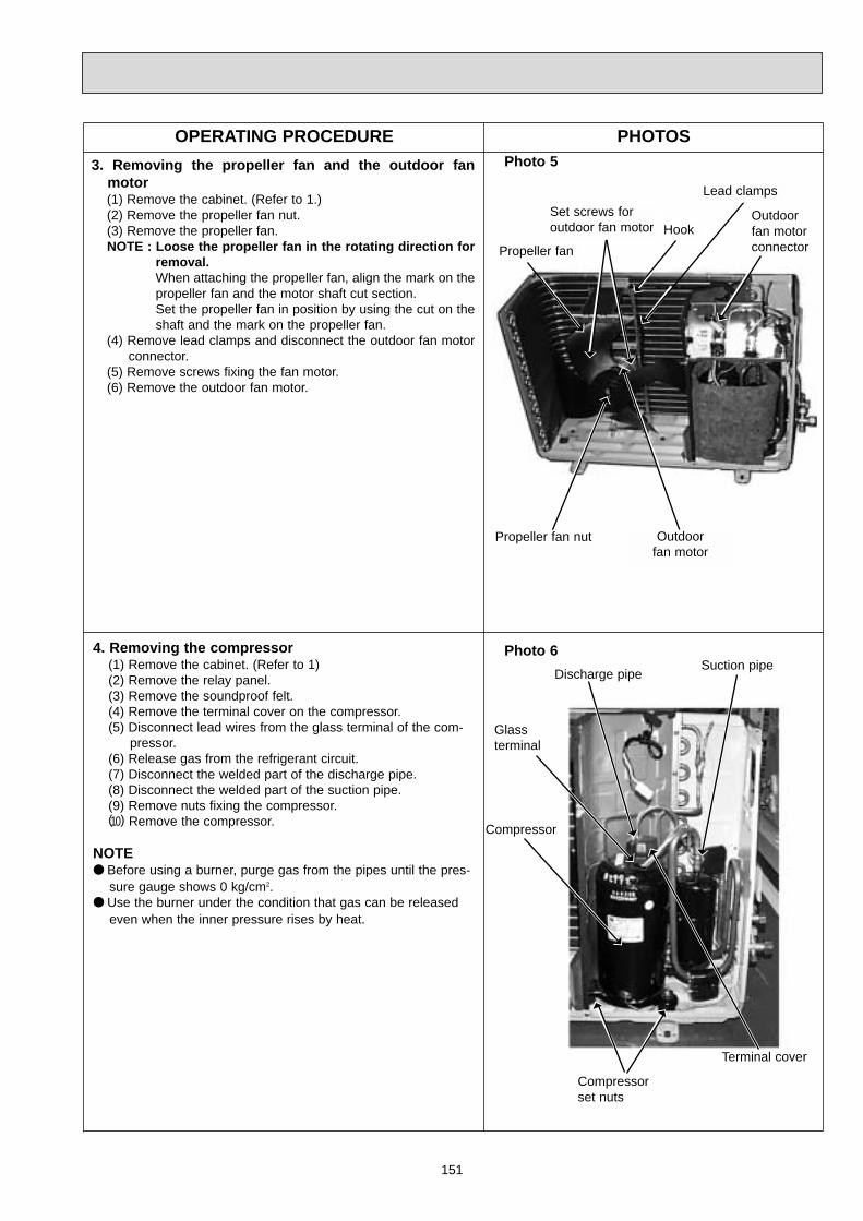
151
OPERATING PROCEDURE PHOTOS
Photo 6
Compressor
Terminal cover
3. Removing the propeller fan and the outdoor fanmotor(1) Remove the cabinet. (Refer to 1.)(2) Remove the propeller fan nut.(3) Remove the propeller fan.NOTE : Loose the propeller fan in the rotating direction for
removal.When attaching the propeller fan, align the mark on thepropeller fan and the motor shaft cut section.Set the propeller fan in position by using the cut on theshaft and the mark on the propeller fan.
(4) Remove lead clamps and disconnect the outdoor fan motorconnector.
(5) Remove screws fixing the fan motor.(6) Remove the outdoor fan motor.
Photo 5
Propeller fan
Propeller fan nut Outdoorfan motor
Set screws foroutdoor fan motor
Lead clamps
Hook
Suction pipeDischarge pipe
4. Removing the compressor(1) Remove the cabinet. (Refer to 1)(2) Remove the relay panel.(3) Remove the soundproof felt.(4) Remove the terminal cover on the compressor.(5) Disconnect lead wires from the glass terminal of the com-
pressor.(6) Release gas from the refrigerant circuit.(7) Disconnect the welded part of the discharge pipe.(8) Disconnect the welded part of the suction pipe.(9) Remove nuts fixing the compressor.(10) Remove the compressor.
NOTE Before using a burner, purge gas from the pipes until the pres-
sure gauge shows 0 kg/cm2. Use the burner under the condition that gas can be released
even when the inner pressure rises by heat.
Compressor set nuts
Glass terminal
Outdoorfan motorconnector

152
OPERATING PROCEDURE PHOTOS
1. Removing the cabinet(1) Remove the screws for the top panel.(2) Remove the screw for the service panel.(3) Remove the screws for the cabinet.(4) Remove the screws for the front panel and motor support.(5) Remove the service panel, and remove the screw from
the insides.(6) Remove the top panel.(7) Remove the cabinet.
2. Removing the deicer P.C. board(1) Remove the service panel and the cabinet.(2) Disconnect all the connectors and the terminals on the
deicer P.C. board.(3) Remove the deicer P.C. board.
14-3. MUH-07RV - MUH-09RV - MUH-12RV -OUTDOOR UNIT
E1E1E1
Photo 4
Terminalblock
ScrewsDeicerP.C. board
Photo 1
Photo 3
Screw fortop panel
Servicepanel
Screw forservice panel
Screw fortop panel
Screws forcabinet
Screws for cabinet
Photo 2
Screws for front panel and motor support
Screws for cabinet
ScrewRelay panel

153
OPERATING PROCEDURE PHOTOS
3. Removing the propeller fan and the outdoor fanmotor(1) Remove the cabinet. (Refer to 1.)(2) Remove the propeller fan nut.(3) Remove the propeller fan.NOTE : Loose the propeller fan in the rotating direction for
removal.When attaching the propeller fan, align the mark on thepropeller fan and the motor shaft cut section.Set the propeller fan in position by using the cut on theshaft and the mark on the propeller fan.
(4) Remove lead clamps and disconnect the outdoor fan motorconnector.
(5) Remove screws fixing the fan motor.(6) Remove the outdoor fan motor.
4. Removing the compressor(1) Remove the cabinet. (Refer to 1)(2) Remove the relay panel.(3) Remove the soundproof felt.(4) Remove the terminal cover on the compressor.(5) Disconnect lead wires from the glass terminal of the com-
pressor.(6) Release gas from the refrigerant circuit.(7) Disconnect the welded part of the discharge pipe.(8) Disconnect the welded part of the suction pipe.(9) Remove nuts fixing the compressor.(10) Remove the compressor.
NOTE Before using a burner, purge gas from the pipes until the pres-
sure gauge shows 0 kg/cm2. Use the burner under the condition that gas can be released
even when the inner pressure rises by heat.
Photo 6
Photo 5
Propeller fan
Propeller fan nut Outdoorfan motor
Set screws foroutdoor fan motor
Lead clamps
Hook
Compressor
Terminal cover
Suction pipeDischarge pipe
Compressor set nuts
Glass terminal
Outdoorfan motorconnector

154
OPERATING PROCEDURE PHOTOS
1. Removing the cabinet.(1) Remove the screws fixing the service panel.(2) Remove the screw fixing the side panel.(3) Remove the service panel.(4) Remove the side panel.(5) Remove the cabinet.
2. Removing the propeller.(1) Remove the cabinet.(2) Remove the propeller nut.(3) Remove the propeller.
Note : Loosen the propeller in the rotating direction for removal.When setting the propeller, align the motor-shaft cut section.
3. Removing the outdoor fan motor.(1) Remove the cabinet. (Refer to 1.)(2) Remove the propeller.(Refer to 2.)(3) Remove the lead clamps and disconnect the outdoor fan
motor connector.(4) Remove outdoor fan motor set screws.(5) Remove the outdoor fan motor.
14-4 MUX-10RV -OUTDOOR UNIT
E1
Screws
Photo 1
Photo 2
Photo 3
Photo 4
Cabinet
Propeller
Outdoor fan motor
Servicepanel
Propeller
Screws
Outdoor fan motorset screws

155
OPERATING PROCEDURE PHOTOS
4. Removing the compressor.(1) Remove the cabinet. (Refer to 1.)(2) Remove the terminal cover.(3) Pull out lead from the compressor terminal, then remove
the thermal protector.(4) Remove the suction pipe welded section and discharge
pipe welded section using a burner.Pull out when the welding melts.
(5) Remove the sound proof felt.(6) Remove the compressor 3 set nuts.(7) Remove the compressor.
Note : Before using the welder, confirm that the pressure gauge is
0 kg/cm2. When using the welder, leave the service port open and release
the pressure to avoid expansion by heat.
Sound proof felt
Photo 5
Dischargepipe
Suctionpipe

156
OPERATING PROCEDURE PHOTOS
1.Removing the cabinet.(1) Remove the screws fixing the service panel.(2) Remove the screw fixing the side panel.(3) Remove the service panel.(4) Remove the side panel.(5) Remove the cabinet.
2. Removing the propeller.(1) Remove the cabinet.(2) Remove the propeller nut.(3) Remove the propeller.
Note: Loosen the propeller in the rotating direction for removal.When setting the propeller, align the motor-shaft cut sec-tion.
3.Removing the outdoor fan motor.(1) Remove the cabinet.(Refer to 1.)(2) Remove the propeller.(Refer to 2.)(3) Remove the lead clamps and disconnect the outdoor fan
motor connector.(4) Remove outdoor fan motor set screws.(5) Remove the outdoor fan motor.
14-5 MUX-18RV -OUTDOOR UNIT
E1
Cabinet
Sidepanel
Side panelset screw
Service panelset screw
Outdoor fan motorset screws
Service panel
Propeller
Fan motor
Propeller nut
Photo 1
Photo 2
Photo 3

157
OPERATING PROCEDURE PHOTOS4. Removing the compressor.
(1) Remove the cabinet.(Refer to 1.)(2) Remove the terminal cover.(3) Pull out lead from the compressor terminal,then remove
the terminal overcurrent relay.(4) Remove the suction pipe welded section and discharge
pipe welded section using a burner.Pull out when the welding melts.
(5) Remove the sound proof felt.(6) Remove the compressor 3 set nuts.(7) Remove the compressor.NOTE: Before using the welder, confirm that the pressure gauge is
0 Kg/cm2. When using the welder, leave the service port open and
release the pressure to avoid expansion by heat.
5. Removing the compressor.(1) Remove the cabinet.(Refer to 1.)(2) Remove the terminal cover.(3) Pull out lead from the compressor terminal,then remove
the terminal overcurrent relay.(4) Remove the screws fixing the back panel.(5) Remove the suction pipe welded section and discharge
pipe welded section using a burner.Pull out when the welding melts.
(6) Remove the sound proof felt.(7) Remove the compressor 3 set nuts.(8) Remove the compressor.
Discharge pipe
Suction pipe
Sound proof felt
Photo 4

158
Screws
OPERATING PROCEDURE PHOTOS
1.Removing the cabinet.(1) Remove the screws fixing the service panel.(2) Remove the screw fixing the top panel.(3) Remove the service panel.(4) Remove the top panel.(5) Remove the screws fixing the front panel.(6) Remove the front panel.(7) Remove the screws fixing the outer nozzle.(8) Remove the outer nozzle.
14-6 MUX-24RV-OUTDOOR UNIT
E1
Front panel
Service panelset
screws
Screws Screws
Top panel
Top panelset screws
Rear panel
Rear panelsetscrews
Photo 1
Photo 2
Photo 3

159
OPERATING PROCEDURE PHOTOS2. Removing the relay panel.
(1) Remove the cabinet. (Refer to 1)(2) Disconnect the following connectors.
. Compressor (MC1,MC2)
. Outdoor fan motor
. Solenoid coil (21R1,21R2,21R3,21R4,21RA,21RB)
3. Removing the propeller.(1) Remove the cabinet.(2) Remove the propeller nut.(3) Remove the propeller.
Note : Loosen the propeller in the rotating direction for removal.When setting the propeller, align the motor-shaft cut section.
4. Removing the outdoor fan motor.(1) Remove the cabinet. (Refer to 1)(2) Remove the propeller. (Refer to 3)(3) Disconnect the connector remove the clamp of outdoor fan
motor lead wire.(4) Remove the screws fixing the outdoor fan motor.
Photo 4
Photo 5
Photo 6
Propeller nutPropeller
Compressor connector(MC1,MC2)
Solenoid coil connector(21R1,21R2,21R3,21R4)
Solenoid coil connector(21RA,21RB)
Screws
Outdoor fan motorset screws
Outdoor fan motor
Clamp

160
OPERATING PROCEDURE PHOTOS5. Removing the compressor. (A,B)
(1) Remove the cabinet. (Refer to 1)(2) Remove the relay panel. (Refer to 2)(3) Remove the terminal cover.(4) Pull out lead from the compressor.(5) Remove the suction pipe welded section and discharge
pipe welded section using a burner. Pull out when thewelding melts.
(6) Remove the sound proof felt.(7) Remove the compressor set nuts.(8) Remove the compressor.
6. Removing the compressor. (C,D)(1) Remove the cabinet. (Refer to 1)(2) Remove the relay panel. (Refer to 2)(3) Remove the screws fixing rear panel. (Refer to photo 2)(4) Remove the rear panel.(5) Remove the terminal cover.(6) Pull out lead from the compressor.(7) Remove the suction pipe welded section and discharge
pipe welded section using a burner. Pull out when thewelding melts.
(8) Remove the sound proof felt.(9) Remove the compressor set nuts.
(10) Remove the compressor.
Photo 7
Sound proof felt Suction pipe Discharge pipe
Terminal cover

161
OPERATING PROCEDURE PHOTOS
Removing the compressor(1) Remove the top panel.(2) Remove the service panel and release the gas.(3) Remove the rear panel, and front panel.(4) Disconnect the compressor linking connector. (See Photo
2.)(5) Disconnect the following connectors from the outdoor elec-
tronic control P.C. board. CN61, CN63, TAB91,CN641,CN671, CN681, CN682, CN761, CN771,CN661,CN683.
(6) Disconnect the reactor lead wires from the terminal +++ ofthe diode stack (DS63) and from the terminal +++ of thecapacitor (C67). (See Photo 3.)
Note: When pulling the wire, push the locking lever of the ter-minal.
(7) Remove the inverter assembly.(8) Remove the band that fixes the discharge pipe muffler.
(See Photo 4.)(9) Remove the propeller fan.(10) Remove the separator and support.(11) Remove the reactor.(12) Remove the terminal cover to disconnect the lead wires
from the compressor terminals.(13) Detach the welded section of the compressor suction pipe
and discharge pipe. (See Photo 4.)(14) Remove the compressor nuts to remove the compressor.
14-7 MXZ-18RV -OUTDOOR UNIT
E1
Photo 3
Photo 1
Photo 2
Photo 4
Suction pipe weld-ed section
Dischargepipe weldedsection
Separator
OutdoorelectroniccontrolP.C. board
Compressorlinking con-nector
Reactor(in housing)
Propeller
Separatorsupport
Top panel
Rear panel
Servicepanel
Connectcover
Front panel
Discharge-pipe mufflerfixing band
Terminal forcapacity(C 67)
Terminal fordiode stack (DS 67)
Outdoor electriccontrol P.C board

162
OPERATING PROCEDURE PHOTOS
Removing the outdoor fan motor(1) Remove the top panel, service panel, and front panel.(2) Disconnect the connector CN63,TAB91 from the outdoor
electronic control P.C. board.(3) Remove the propeller.(4) Remove the outdoor fan motor.
Photo 4
Propeller
Fan motor

163
OPERATING PROCEDURE PHOTOS
1.Removing the compressor(1)Remove the screws fo the service panel, and remove it.
Release refrigerant gas.(2)Remove the screws of the top panel , and remove it.(3)Remove the screws of the front panel , and remove it.(4)Disconnect the compressor lead wire.(TAB64,TAB65,TAB66)(5)Disconnect the ourdoor controller board connectors CN791,
CN792, CN723, CN722,CN662, and CN661.Disconnect thenoise filter board connectors CN913, CN912, and CN911.
(6)Remove the four screws of the electrical parts , and removethem.
(7)Remove the propeller.(8)Remove the screws of the separator, and remove it.(9)Detach the brazed joints of the compressor suction and dis-
charge pipes.(See Photo 3.)(10)Remove the three compressor nuts and remove the com-
pressor.
Photo 1
Top panel
Service panel
Front panel
Photo 2
Photo 3
Control P.C.board
Electrical parts
Terminal
Sepatator
Discharge pipebrazed part
Suction pipebraxed part
14-7 MXZ-32RV -OUTDOOR UNIT
E1

164
OPERATING PROCEDURE PHOTOS
3.Removing the 4-way valve(1)Remove the screws of the top panel , and remove it.(See
Photo 1.)(2)Remove the service panel,rear panel,and connect cover
panel.Release refrigerant gas.(3)Remove the electrical parts.(See Photo 2.)(4)Detach the brazed joint of 4-way valve and pipe.(See Photo
4.)
4.Removing the linear expansion valve(1)Remove the service panel.(See Photo 1.)(Gas release is not required if the unit is pumped down.)(2)Remove the coil of linear expansion valve.(3)Detach the brazed joint of linear expansion valve and pipe.
4 way valve
4 way valve coil
Brazing area
Linear expansionvalve coil
Linear expansionvalve
Photo 4
Photo 5
2.Removing the fan motor(1)Remove the top panel(five screws),the service panel(four
screws),and the front panel (two screws).(See Photo 1.)(2)Disconnect the connector CN911 on the outdoor controller
board.(3)Remove the propeller.(4)Remove the fan motor.

165
OPERATING PROCEDURE PHOTOS5.Removing the reactor(1)Remove the five screws of the top panel , and remove it.(See
Photo 1.)(2)Disconnect the reactor lead wire.(3)Remove the two screws of the reactor , and take it out.
Reactor
Photo 6

166
12
3
4
56789101112
E02 424 000E02 424 010E02 408 100E02 410 100E02 409 234E02 411 234E02 409 976E02 409 975E02 408 970E02 409 067E02 408 142E02 424 020
FRONT PANEL(WH)GRILLE(WH)AIR FILTERAIR FILTERBOX(WH)BOX(WH)CORNER BOX (LEFT)CORNER BOX (RIGHT)INSTALLATION PLATESCREW CAP(WH)CATCHDECORATION COVERAIR CLEANING FILTERDEODORIZING FILTER
Symbol
in Wiring
Diagram
Q'ty/unit
112
1
11123111
2PCS/SET3PCS/SET
MAC-1300FTMAC-1800DF
RemarksPart No.No. Part Name MSC-07RV- (WH)E1
MSC-12RV- (WH)E1
MSC-09RV- (WH)E1
11
2
111123111
112
1
11123111
11(See page 184.)
4 (W)
61
5
2
MSC-07RV - (WH)MSC-09RV - (WH)MSC-12RV - (WH)E1
E1
E1
8
7
12(See page 184.)
15-2. ACCESSORY PART
E02 141 08313 REMOTE CONTROLLER HOLDER 1 11
15-1. INDOOR UNIT STRUCTURAL PARTS
15-1.INDOOR UNIT STRUCTURAL PARTS
9 3 (W)
13
15-2. ACCESSORY PART
15 PARTS LIST
10
(W)These figures show about MSC-12RV.

167
Symbolin WiringDiagram
Q'ty/unitRemarksPart No.No. Part Name MSC-07RV
- (WH)E1MSC-09RV- (WH)E1
MSC-12RV- (WH)E1
E02 409 235E02 409 040E02 409 041E02 408 702E02 001 504E02 408 303E02 151 300E02 151 505E02 408 302E02 408 509E02 408 308E02 408 307E02 424 375E02 424 452E02 425 452E02 426 452E02 424 395E02 408 034E02 127 382E02 336 385
12345678910111213
14
15161718
NOZZLE (WH)VANE UPPER (WH)VANE LOWER (WH)DRAIN HOSESLEEVE BEARINGVANE MOTORINDOOR FAN MOTORFAN MOTOR RUBBER MOUNTLINE FLOW FANBEARING MOUNTROOM TEMPERATURE THERMISTORINDOOR COIL THERMISTORTERMINAL BLOCKELECTRONIC CONTROL P.C.BOARDELECTRONIC CONTROL P.C.BOARDELECTRONIC CONTROL P.C.BOARDPOWER SUPPLY CORD
VANE MOTOR SUPPORT SETFUSEVARISTOR
RC4V19-2PCS/SET
AUTO RESTARTAUTO RESTARTAUTO RESTART
3.15A
MVMF
RT11RT12TB
F11NR11
1111111211111
1
1111
11111112111111
1111
1111111211111
1 1111
15-3. INDOOR UNIT ELECTRICAL PARTS
19 (W)
2021
E02 408 620E02 410 620E02 151 666E02 155 666E02 151 667
19
20
21
INDOOR HEAT EXCHANGERINDOOR HEAT EXCHANGERUNION(GAS)UNION(GAS)UNION(LIQUID)
1
1
1
9.5212.76.35
1
1
1
1
11
14
11
2
4
3
6
8
1
9
7
10 12
13
15
17
1618
15-4. INDOOR UNIT HEAT EXCHANGER
15-3. INDOOR UNIT ELECTRICAL PARTS
15-4. INDOOR UNIT HEAT EXCHANGER
MSC-07RV - (WH)MSC-09RV - (WH)MSC-12RV - (WH)E1
E1
E1
SLEEVE BEARING
ROOM TEMPERATURETHERMISTOR
FUSE
VARISTOR
5
(W)These figures show about MSC-12RV.

168
No. Part No. Part name RemarksSymbol
in WiringDiagram
Q'ty/unit
1234
5
6
7
8
9
10
11
12
13
E02 336 232E02 336 297E02 336 521E02 336 245E02 437 900E02 438 900E02 141 900E02 336 630E02 339 936E02 412 936E02 339 662E02 339 661E02 340 661E02 339 290E02 340 290E02 336 515E02 336 506E02 075 506E02 339 233
CABINETTOP PANELGRILLE(OUT)SERVICE PANELCOMPRESSORCOMPRESSORCOMPRESSOROUTDOOR HEAT EXCHANGERCAPILLARY TUBECAPILLARY TUBESTOP VALVE(LIQUID)STOP VALVE(GAS)STOP VALVE(GAS)BASEBASEMOTOR SUPPORTCOMPRESSOR RUBBER SETCOMPRESSOR RUBBER SETBACK PANEL
RH-135VGCTRH-145VGCTRH-231VHAT
3.0x1.4x6003.0x1.6x6006.359.5212.7
3RUBBERS/SET3RUBBERS/SET
1111
1
11
11
1
13
1
MCMCMC
MU-12RV- E1MU-07RV- E1 MU-09RV- E1
11111
11
11
1
13
1
1111
11
11
1
11
31
2
3
5 10 912
1
8
11
6
413
Part number that is circled is not shown in the illustration.
15-5. OUTDOOR UNIT STRUCTURAL PARTSMU-07RV -MU-09RV -MU-12RV - E1
E1
E1

169
No. Part No. Part name RemarksSymbol
in WiringDiagram
Q'ty/unit
1
2
3
456789
E02 336 501E02 437 301E02 439 301E02 085 353E02 079 353E02 437 374E02 438 374E02 095 350E02 001 340E02 095 382E02 128 383
PROPELLER FANOUTDOOR FAN MOTOROUTDOOR FAN MOTORCOMPRESSOR CAPACITORCOMPRESSOR CAPACITORTERMINAL BLOCKTERMINAL BLOCKOUTDOOR FAN CAPACITORCONTACTORFUSESURGE ABSORBER
RA6V23-RA6V33-25+ /440V30+ /440V
1.5+ /440V
250V2A
MFMFC1C1
TB1TB2C2
52CF
DSAR
11
1
111111
MU-12RV- E1MU-07RV- E1 MU-09RV- E1
11
1
111111
1
1
1111111
1 2 6 3
5 4
15-6. OUTDOOR UNITFUNCTIONAL PARTS ANDELECTRICAL PARTS
E02 408 42610 REMOTE CONTROLLER 1 11
15-7. REMOTE CONTROLLER
15-7. REMOTE CONTROLLER
10
15-6. OUTDOOR UNIT FUNCTIONAL PARTS AND ELECTRICAL PARTS
MU-07RV -MU-09RV -MU-12RV - E1
E1
E1
Part number that are circled are not shown in the illustration.

170
No. Part No. Part name RemarksSymbol
in WiringDiagram
Q'ty/unit
1234
5
6
7
8
9
10
11
12
131415
E02 336 232E02 336 297E02 336 521E02 336 245E02 164 900E02 128 900E02 141 900E02 440 630E02 442 630E02 159 936E02 156 936E02 339 936E02 441 936E02 412 936E02 134 937E02 134 936E02 442 936E02 139 662E02 339 661E02 340 661E02 339 290E02 340 290E02 336 515E02 442 515E02 336 506E02 075 506E02 440 233E02 444 961E02 154 642
CABINETTOP PANELGRILLE(OUT)SERVICE PANELCOMPRESSORCOMPRESSORCOMPRESSOROUTDOOR HEAT EXCHANGEROUTDOOR HEAT EXCHANGERCAPILLARY TUBECAPILLARY TUBECAPILLARY TUBECAPILLARY TUBECAPILLARY TUBECAPILLARY TUBECAPILLARY TUBECAPILLARY TUBESTOP VALVE(LIQUID)STOP VALVE(GAS)STOP VALVE(GAS)BASEBASEMOTOR SUPPORTMOTOR SUPPORTCOMPRESSOR RUBBER SETCOMPRESSOR RUBBER SETBACK PANELREVERSING VALVECHECK VALVE
RH-135VGHTRH-174VGHTRH-231VHAT
3.0x1.4x8003.0x1.4x5003.0x1.4x6003.0x1.4x5503.0x1.6x6003.0x1.6x4003.0x1.6x7003.0x1.8x3006.359.5212.7
3RUBBERS/SET3RUBBERS/SET
1111
1
1
2
1
1
11
1
1
3
111
MCMCMC
MUH-12RV- E1MUH-07RV- E1 MUH-09RV- E1
11111
1
2
1
1
11
1
1
3
111
1111
1
1
2
111
1
1
1
3111
2
3
5 10 912
1
8
11
6
413
Part number that are circled are not shown in the illustration.
14
15-8. OUTDOOR UNIT STRUCTURAL PARTSMUH-07RV -MUH-09RV -MUH-12RV - E1
E1
E1

171
No. Part No. Part name RemarksSymbol
in WiringDiagram
Q'ty/unit
1
2
3
45
6
7891011
E02 336 501E02 440 301E02 442 301E02 085 353E02 079 353E02 437 374E02 440 374E02 289 310E02 440 310E02 440 451E02 128 383E02 440 490E02 095 382E02 085 385
PROPELLER FANOUTDOOR FAN MOTOROUTDOOR FAN MOTORCOMPRESSOR CAPACITORCOMPRESSOR CAPACITORTERMINAL BLOCKTERMINAL BLOCKDEFROST THERMISTORDEFROST THERMISTORDEICER P.C. BOARDSURGE ABSORBERREVERSING VALVE COILFUSEVARISTOR
RA6V23-RA6V33-25+ /440V30+ /440V
250V 2A
MFMFC1C1
TB1TB2RT61RT61
DSAR21S4F61
NR61
11
1
111
11111
MUH-12RV- E1MUH-07RV- E1 MUH-09RV- E1
11
1
111
11111
1
1
111
111111
1 2 73
6 5 4
8
15-9. OUTDOOR UNITFUNCTIONAL PARTS ANDELECTRICAL PARTS
E02 430 42612 REMOTE CONTROLLER 1 11
15-10. REMOTE CONTROLLER
15-10. REMOTE CONTROLLER
12
15-9. OUTDOOR UNIT FUNCTIONAL PARTS AND ELECTRICAL PARTS
MUH-07RV -MUH-09RV -MUH-12RV - E1
E1
E1
Part number that are circled are not shown in the illustration.
15-11. ACCESSORY PARTS
E02 440 704E02 440 705
1314
DRAIN SOCKETDRAIN CAP
12
12
12
15-11. ACCESSORY PARTS
13 14

172
MUX-10RV -15-12. OUTDOOR UNITFUNCTIONAL PARTS AND ELECTRICAL PARTS
E1
No. Parts No. Parts Name Remarks
Q'ty / unit
MUX-10RV- E1
Symbolin WiringDiagram
Part number that is circled are not shown in the illustration.
1
2
3
4
5
6
7
8
9
10
11
12
13
14
M21 601 501
T2W E42 301
T2W E42 388
T2W E39 389
T2W E42 389
T2W E60 375
M21 370 378
T2W 459 342
M21 N71 350
T2W 304 353
T2W E03 330
M21 B00 340
T2W E60 376
T2W A79 382
PROPELLER FAN
OUTDOOR FAN MOTOR
BYPASS VALVE SOLENOID COIL A
BYPASS VALVE SOLENOID COIL B
BYPASS VALVE SOLENOID COIL
TERMINAL BLOCK
TERMINAL BLOCK
COMPRESSOR CONTACTOR
FAN MOTOR CAPACITOR
COMPRESSOR CAPACITOR
OVERCURRENT RELAY
RELAY
TERMINAL BLOCK
FUSE
1
1
1
1
1
1
2
2
1
1
1
2
1
2
RA6V22-
L N
1.5+440V
17+440V
G4F11123T
2,1,2,1
2A 250V
MF
21R1
21R2
21R
TB
TB
52C1,52C2
C2
C1
51C
TB
F12,F13
15 E02 408 426 REMOTE CONTROLLER 2
1
2 3 4 5
9 10 7
6
8
15-13. REMOTE CONTROLLER
15
15-12. OUTDOOR UNIT FUNCTIONAL PARTS AND ELECTRICAL PARTS
15-13. REMOTE CONTROLLER

173
15-14. OUTDOOR UNITSTRUCTURAL PARTSMUX-10RV - E1
No. Parts No. Parts Name RemarksMUX-10RV- E1
Symbolin WiringDiagram
Q'ty / unit
1
2
3
4
5
6
7
8
9
10
11
12
13
14
15
T2W 418 521
T2W E03 232
M21 478 297
T2W 459 630
T2W 416 515
T2W E03 293
M21 179 645
M21 463 936
M21 195 648
M21 K08 936
T2W E42 662
T2W E42 661
T2W E03 290
T92 514 200
T2W E03 245
OUTER NOZZLE
CABINET
TOP PANEL
OUTDOOR HEAT EXCHANGER
MOTOR SUPPORT
SEPARATOR
SOLENOID VALVE
CAPILLARY TUBE ([3.0x[1.4x1900)
SOLENOID VALVE
CAPILLARY TUBE ([3.0x[1.6x1200)
STOP VALVE(LIQUID)
STOP VALVE
BASE ASSEMBLY
COMPRESSOR
SERVICE PANEL
1
1
1
1
1
1
2
1
1
1
2
2
1
1
1
[3.0x[1.4x400[3.0x[1.4x400
[3.0x[1.6x1000
KH-134VLLMC
When servicing , cut the tube to the propper length as shown in the REFRIGERANT SYSTEM DIAGRAM.See page 38.
10
3 4 5 6 7
8
9
11
12
13
1415
1
2

174
15-15. OUTDOOR UNITFUNCTIONAL PARTS AND AND ELECTRICAL PARTS AND STRUCTURAL PARTSMUX-18RV - E1
3531
5
122 27 17 16
9
8 11 10 7 28 6
15
1413
18
19242524252021
2223
302826
4
1
3
15-16. REMOTE CONTROLLER
37
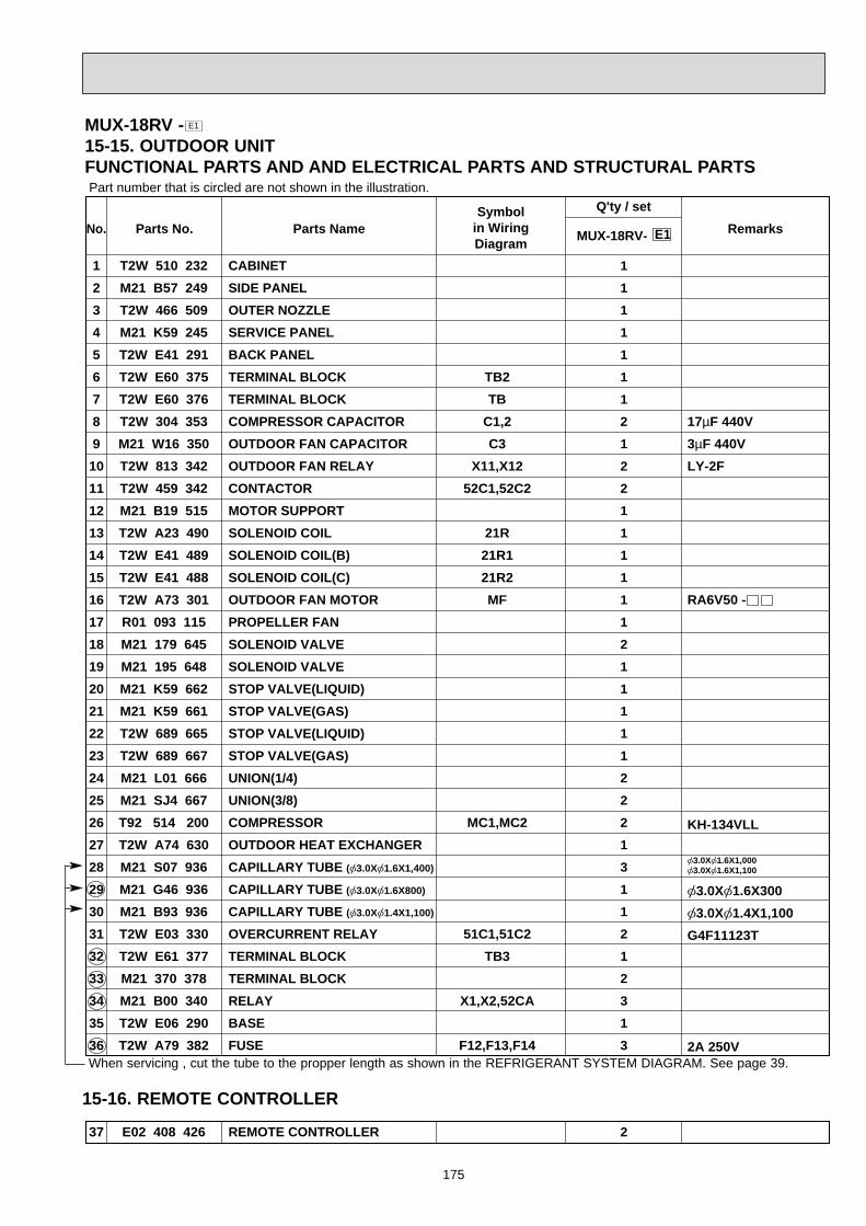
175
No. Parts No. Parts Name RemarksMUX-18RV- E1
Symbolin WiringDiagram
Q'ty / setPart number that is circled are not shown in the illustration.
1
2
3
4
5
6
7
8
9
10
11
12
13
14
15
16
17
18
19
20
21
22
23
24
25
26
27
28
29
30
31
32
33
34
35
36
T2W 510 232
M21 B57 249
T2W 466 509
M21 K59 245
T2W E41 291
T2W E60 375
T2W E60 376
T2W 304 353
M21 W16 350
T2W 813 342
T2W 459 342
M21 B19 515
T2W A23 490
T2W E41 489
T2W E41 488
T2W A73 301
R01 093 115
M21 179 645
M21 195 648
M21 K59 662
M21 K59 661
T2W 689 665
T2W 689 667
M21 L01 666
M21 SJ4 667
T92 514 200
T2W A74 630
M21 S07 936
M21 G46 936
M21 B93 936
T2W E03 330
T2W E61 377
M21 370 378
M21 B00 340
T2W E06 290
T2W A79 382
CABINET
SIDE PANEL
OUTER NOZZLE
SERVICE PANEL
BACK PANEL
TERMINAL BLOCK
TERMINAL BLOCK
COMPRESSOR CAPACITOR
OUTDOOR FAN CAPACITOR
OUTDOOR FAN RELAY
CONTACTOR
MOTOR SUPPORT
SOLENOID COIL
SOLENOID COIL(B)
SOLENOID COIL(C)
OUTDOOR FAN MOTOR
PROPELLER FAN
SOLENOID VALVE
SOLENOID VALVE
STOP VALVE(LIQUID)
STOP VALVE(GAS)
STOP VALVE(LIQUID)
STOP VALVE(GAS)
UNION(1/4)
UNION(3/8)
COMPRESSOR
OUTDOOR HEAT EXCHANGER
CAPILLARY TUBE ([3.0X[1.6X1,400)
CAPILLARY TUBE ([3.0X[1.6X800)
CAPILLARY TUBE ([3.0X[1.4X1,100)
OVERCURRENT RELAY
TERMINAL BLOCK
TERMINAL BLOCK
RELAY
BASE
FUSE
1
1
1
1
1
1
1
2
1
2
2
1
1
1
1
1
1
2
1
1
1
1
1
2
2
2
1
3
1
1
2
1
2
3
1
3
17µF 440V
3µF 440V
LY-2F
RA6V50 -
KH-134VLL
[3.0X[1.6X1,000[3.0X[1.6X1,100
[3.0X[1.6X300
[3.0X[1.4X1,100
G4F11123T
2A 250V
TB2
TB
C1,2
C3
X11,X12
52C1,52C2
21R
21R1
21R2
MF
MC1,MC2
51C1,51C2
TB3
X1,X2,52CA
F12,F13,F14
37 E02 408 426 REMOTE CONTROLLER 2
When servicing , cut the tube to the propper length as shown in the REFRIGERANT SYSTEM DIAGRAM. See page 39.
MUX-18RV -15-15. OUTDOOR UNITFUNCTIONAL PARTS AND AND ELECTRICAL PARTS AND STRUCTURAL PARTS
E1
15-16. REMOTE CONTROLLER

176
15-17. OUTDOOR UNIT FUNCTIONAL PARTS AND AND ELECTRICAL PARTSMUX-24RV - E1
56
12 8 7 18 13
9
17
12
14
154
10
11
3
No. Parts No. Parts Name RemarksMUX-24RV- E1
Symbolin WiringDiagram
Q'ty / unitPart number that is circled is not shown in the illustration.
1
2
3
4
5
6
7
8
9
10
11
12
13
14
15
16
17
18
T2W E44 301
M21 17A 501
T2W E44 388
T2W E44 389
T2W E38 388
T2W E38 389
T2W E37 388
T2W E37 389
T2W 813 342
M21 B00 340
T2W 459 342
T2W E06 353
T2W A62 353
T2W E62 375
T2W E44 375
M21 020 378
T2W E08 381
T2W 779 353
FAN MOTOR
PROPELLER FAN
SOLENOID COIL
SOLENOID COIL
SOLENOID COIL
SOLENOID COIL
SOLENOID COIL
SOLENOID COIL
FAN MOTOR RELAY
RELAY
COMPRESSOR RELAY
FAN MOTOR CAPACITOR
COMPRESSOR CAPACITOR
TERMINAL BLOCK
TERMINAL BLOCK
TERMINAL BLOCK
FUSE
COMPRESSOR CAPACITOR
1
1
1
1
1
1
1
1
2
4
4
1
1
1
4
6
1
1
LY-2F
G4F11123T-MT
AC200/240V
3=/440V
30=/420V
3.15A 250V
25=/420V
MF
21R1
21R2
21R3
21R4
21RA
21RB
X11,X12
X1,X2,X3,X4
52C1,52C2
52C3,52C4
C1
TB
TB1,TB2
TB3,TB4
TB5,6,7,8,9,10
C2
19 E02 408 426 REMOTE CONTROLLER 3
15-17. OUTDOOR UNIT FUNCTIONAL PARTS AND AND ELECTRICAL PARTS
15-18. REMOTE CONTROLLER
19
15-18. REMOTE CONTROLLER
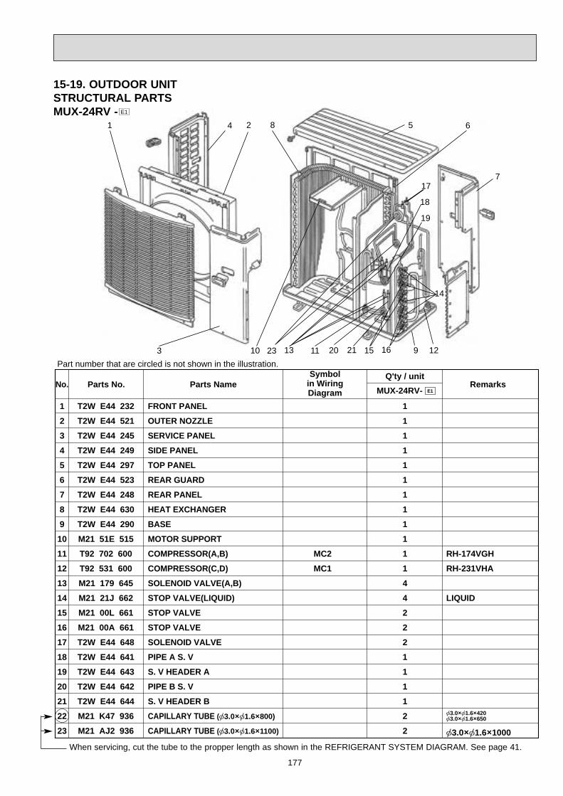
177
No. Parts No. Parts Name RemarksMUX-24RV- E1
Symbolin WiringDiagram
Q'ty / unitPart number that are circled is not shown in the illustration.
1
2
3
4
5
6
7
8
9
10
11
12
13
14
15
16
17
18
19
20
21
22
23
T2W E44 232
T2W E44 521
T2W E44 245
T2W E44 249
T2W E44 297
T2W E44 523
T2W E44 248
T2W E44 630
T2W E44 290
M21 51E 515
T92 702 600
T92 531 600
M21 179 645
M21 21J 662
M21 00L 661
M21 00A 661
T2W E44 648
T2W E44 641
T2W E44 643
T2W E44 642
T2W E44 644
M21 K47 936
M21 AJ2 936
FRONT PANEL
OUTER NOZZLE
SERVICE PANEL
SIDE PANEL
TOP PANEL
REAR GUARD
REAR PANEL
HEAT EXCHANGER
BASE
MOTOR SUPPORT
COMPRESSOR(A,B)
COMPRESSOR(C,D)
SOLENOID VALVE(A,B)
STOP VALVE(LIQUID)
STOP VALVE
STOP VALVE
SOLENOID VALVE
PIPE A S. V
S. V HEADER A
PIPE B S. V
S. V HEADER B
CAPILLARY TUBE ([3.0O[1.6O800)
CAPILLARY TUBE ([3.0O[1.6O1100)
1
1
1
1
1
1
1
1
1
1
1
1
4
4
2
2
2
1
1
1
1
2
2
RH-174VGH
RH-231VHA
LIQUID
[3.0O[1.6O420[3.0O[1.6O650
[3.0O[1.6O1000
MC2
MC1
1 4 2
3 13 11 20 21 15 16 9 12
7
14
19
18
17
658
10
15-19. OUTDOOR UNIT STRUCTURAL PARTSMUX-24RV - E1
When servicing, cut the tube to the propper length as shown in the REFRIGERANT SYSTEM DIAGRAM. See page 41.
23
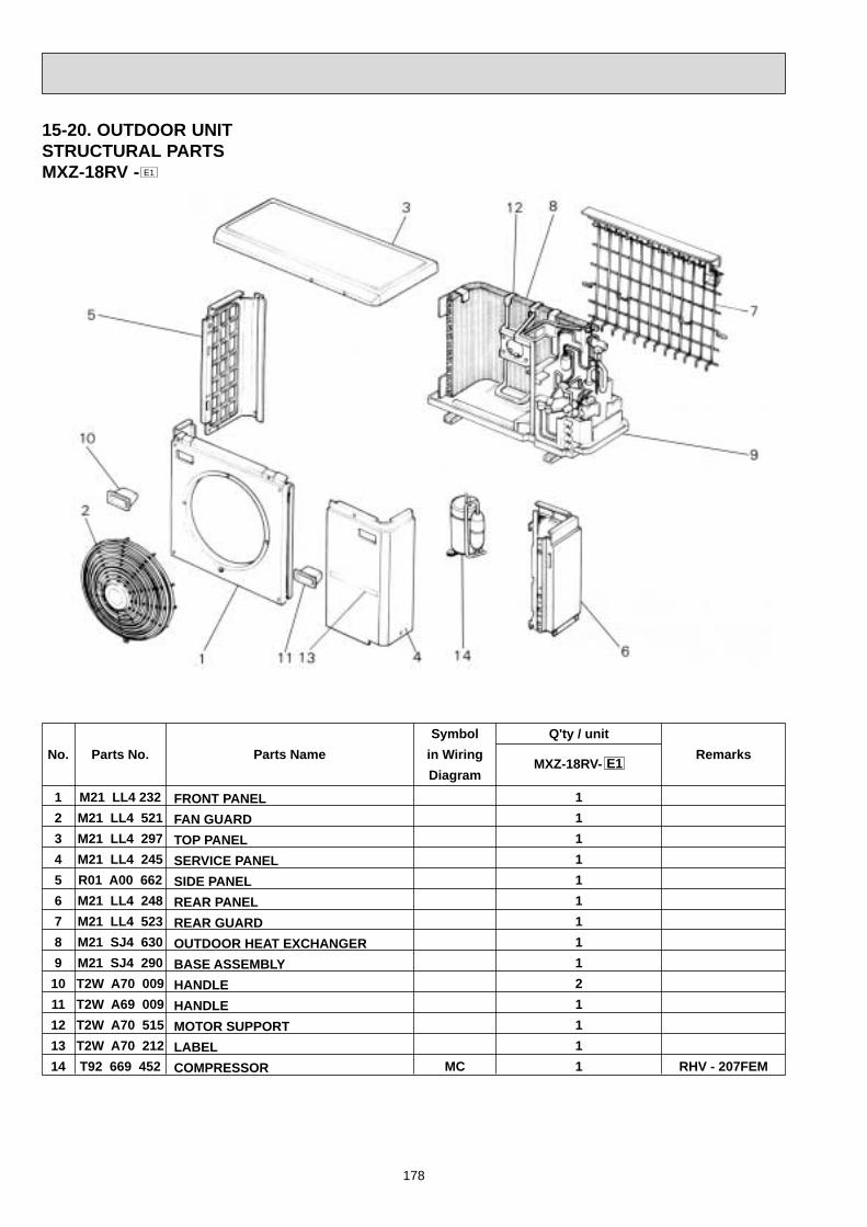
178
15-20. OUTDOOR UNITSTRUCTURAL PARTSMXZ-18RV - E1
1
2
3
4
5
6
7
8
9
10
11
12
13
14
M21 LL4 232
M21 LL4 521
M21 LL4 297
M21 LL4 245
R01 A00 662
M21 LL4 248
M21 LL4 523
M21 SJ4 630
M21 SJ4 290
T2W A70 009
T2W A69 009
T2W A70 515
T2W A70 212
T92 669 452
FRONT PANEL
FAN GUARD
TOP PANEL
SERVICE PANEL
SIDE PANEL
REAR PANEL
REAR GUARD
OUTDOOR HEAT EXCHANGER
BASE ASSEMBLY
HANDLE
HANDLE
MOTOR SUPPORT
LABEL
COMPRESSOR MC
1
1
1
1
1
1
1
1
1
2
1
1
1
1
No. Parts Name
Symbol
in Wiring
Diagram
Parts No.
Q'ty / unit
MXZ-18RV-Remarks
RHV - 207FEM
E1

179
15-21. OUTDOOR UNITFUNCTURAL PARTSMXZ-18RV - E1
Part number that are circed are not shown in the illustration.
1
2
3
4
5
6
7
8
9
10
11
12
13
14
M21 LL4 501
T2W E41 301
M21 LL4 488
M21 LL4 487
M21 LL4 646
M21 SJ4 667
M21 SJ4 666
T2W A64 668
T7W 250 403
T2W E41 646
M21 LL4 939
M21 LL4 938
M21 986 936
M21 L11 936
PROPELLER FAN
OUTDOOR FAN MOTOR
EXPANSION VALVE (COIL)
EXPANSION VALVE (COIL)
EXPANSION VALVE
UNION (3/8F)
UNION (1/4F)
BALL VALVE (3/8)
REVERSING VALVE
HIGH PRESSURE SWITCH
ACCUMULATOR
MUFFLER
CAPILLARY TUBE ([4.0 [2.4 2000)
CAPILLARY TUBE ([2.0 [0.6 1000)
MF
LEV. A
LEV. B
HPS
1
1
1
1
2
2
2
2
1
1
1
1
1
1
No. Parts Name
Symbol
in Wiring
Diagram
Parts No.
Q'ty / unit
MXZ-18RV-Remarks
RA6V50-
[4.0 [2.4 300[4.0 [2.4 400
[2.0 [0.6 500
E1
When servicing, cut the tube to the propper length as shown in the REFRIGERANT SYSTEM DIAGRAM. See page 43.
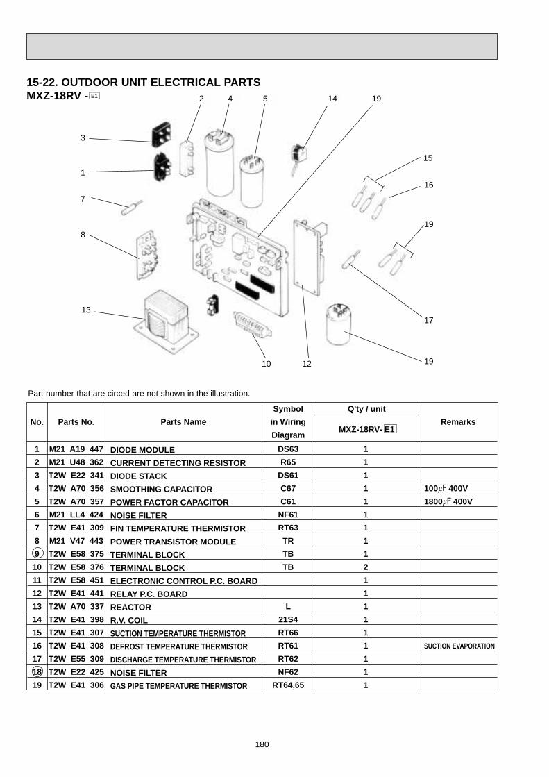
180
15-22. OUTDOOR UNIT ELECTRICAL PARTSMXZ-18RV - E1
15
16
19
Part number that are circed are not shown in the illustration.
1
2
3
4
5
6
7
8
9
10
11
12
13
14
15
16
17
18
19
M21 A19 447
M21 U48 362
T2W E22 341
T2W A70 356
T2W A70 357
M21 LL4 424
T2W E41 309
M21 V47 443
T2W E58 375
T2W E58 376
T2W E58 451
T2W E41 441
T2W A70 337
T2W E41 398
T2W E41 307
T2W E41 308
T2W E55 309
T2W E22 425
T2W E41 306
DIODE MODULE
CURRENT DETECTING RESISTOR
DIODE STACK
SMOOTHING CAPACITOR
POWER FACTOR CAPACITOR
NOISE FILTER
FIN TEMPERATURE THERMISTOR
POWER TRANSISTOR MODULE
TERMINAL BLOCK
TERMINAL BLOCK
ELECTRONIC CONTROL P.C. BOARD
RELAY P.C. BOARD
REACTOR
R.V. COIL
SUCTION TEMPERATURE THERMISTOR
DEFROST TEMPERATURE THERMISTOR
DISCHARGE TEMPERATURE THERMISTOR
NOISE FILTER
GAS PIPE TEMPERATURE THERMISTOR
DS63
R65
DS61
C67
C61
NF61
RT63
TR
TB
TB
L
21S4
RT66
RT61
RT62
NF62
RT64,65
1
1
1
1
1
1
1
1
1
2
1
1
1
1
1
1
1
1
1
No. Parts Name
Symbol
in Wiring
Diagram
Parts No.
Q'ty / unit
MXZ-18RV- E1Remarks
100+ 400V
1800+ 400V
SUCTION EVAPORATION
17
7
14
13
12
19
10
8
1
2
3
4 5
19

181
Part number that is circled are not shown in the illustration.
1
2
3
4
5
6
7
8
9
10
11
12
13
14
15
16
17
18
19
20
M21 17A 501
T2W E40 301
T2W E40 452
M21 17A 447
M21 17A 443
M21 17E 337
T2W E40 357
T2W E40 356
T2W E59 451
T2W E40 424
T2W E58 375
T2W E58 376
M21 42A 340
M21 42E 307
M21 42A 308
T2W E40 646
M21 17A 362
M21 41V 308
T2W E40 389
T2W E40 441
PROPELLER FAN
OUTDOOR FAN MOTOR
IPM P.C. BOARD
DIODE STACK
DIODE MODULE
REACTOR
POWER FACTOR CAPACITOR
SMOOTHING CAPACITOR
CONTROL P.C. BOARD
NOISE FILTER BOARD
TERMINAL BLOCK
TERMINAL BLOCK
RELAY
GAS PIPE TEMPERATUR THERMISTOR
FIN TEMPERATURE THERMISTOR
H.P. SWITCH
RESISTOR
THERMISTOR
SOLENOID COIL
RELAY P.C. BOARD
MF61
DS62
DS61
L
C61
C62,C63
TB3
TB2
X64
RT66,67,68,69
RT63
63H2
R
RT61,62,64,65
21S4,21S2
1
1
1
1
1
1
1
2
1
1
4
1
1
1
1
1
1
1
1
1
No. Parts Name
Symbol
in Wiring
Diagram
Parts No.
Q'ty / unit
MXZ-32RV-Remarks
200+ 400V
200+ 400V
A,B,C,D
3.43MPa(35kg/j)
SUCTION ,EVAPORATIONDISCHARGE,DEFROST
SOLENOID,R.V./SET
E1
15-23. OUTDOOR UNIT STRUCTURAL PARTSMXZ-32RV - E1

182
15-24. OUTDOOR UNIT FUNCTIONAL PARTSMXZ-32RV - E1
1
2
3
4
5
6
7
8
9
10
11
12
13
14
15
16
17
18
19
20
21
22
23
M21 17A 232
M21 17A 245
M21 17A 249
M21 17A 297
T2W E40 523
T2W E40 248
T2W E40 247
T7W 250 403
M21 17A 647
M21 B20 646
M21 17A 640
M21 42E 644
M21 41V 651
M21 41V 652
M21 42A 653
M21 42E 651
T2W E40 438
M21 17A 290
M21 42E 630
T92 500 700
T2W E59 936
M23 K89 936
M21 L11 936
FRONT PANLE
SERVICE PANEL
SIDE PANEL
TOP PANEL
REAR GUARD
REAR PANEL
C. COVER
REVERSING VALVE
L.P. SWICH
H.P. SWICH
2 WAY VALVE
UNION
EXPANSION VALVE
EXPANSION VALVE
EXPANSION VALVE
EXPANSION VALVE
CRANKCASE HEATER
BASE ASSEMBLY
HEAT EXCHANGER
COMPRESSOR
CAPILLARY TUBE([2.5O[0.6O1000)
CAPILLARY TUBE([3.0O[2.0O900)
CAPILLARY TUBE([2.0O[0.6O1000)
63L
63H1
MC
1
1
1
1
1
1
1
1
1
1
1
1
1
1
1
1
1
1
1
1
1
2
1
No. Parts Name
Symbol
in Wiring
Diagram
Parts No.
Q'ty / unit
MXZ-32RV-Remarks
1/2,3/8,1/4 SET
A room
B room
C room
D room
CHV-253FAA
[2.5O[0.6O750
[3.0O[2.0O500
[2.0O[0.6O1000
E1
Part number that is circled are not shown in the illustration.
15
7
1720
6
12
191
2
3 4
13 14119
10 85
18
When servicing , cut the tube to the propper length as shown in the REFRIGERANT SYSTEM DIAGRAM.See page 43.
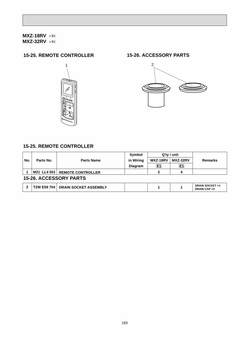
2
1 M21 LL4 501 REMOTE CONTROLLER 2 4
No. Parts Name
Symbol
in Wiring
Diagram
Parts No.
Q'ty / unit
MXZ-18RV Remarks
E1 E1
MXZ-32RV
T2W E59 704 DRAIN SOCKET ASSEMBLY 1 1 DRAIN SOCKET O1DRAIN CAP O2
183
15-25. REMOTE CONTROLLER
1
15-26. ACCESSORY PARTS
2
MXZ-18RV -MXZ-32RV - E1
E1
15-25. REMOTE CONTROLLER
15-26. ACCESSORY PARTS
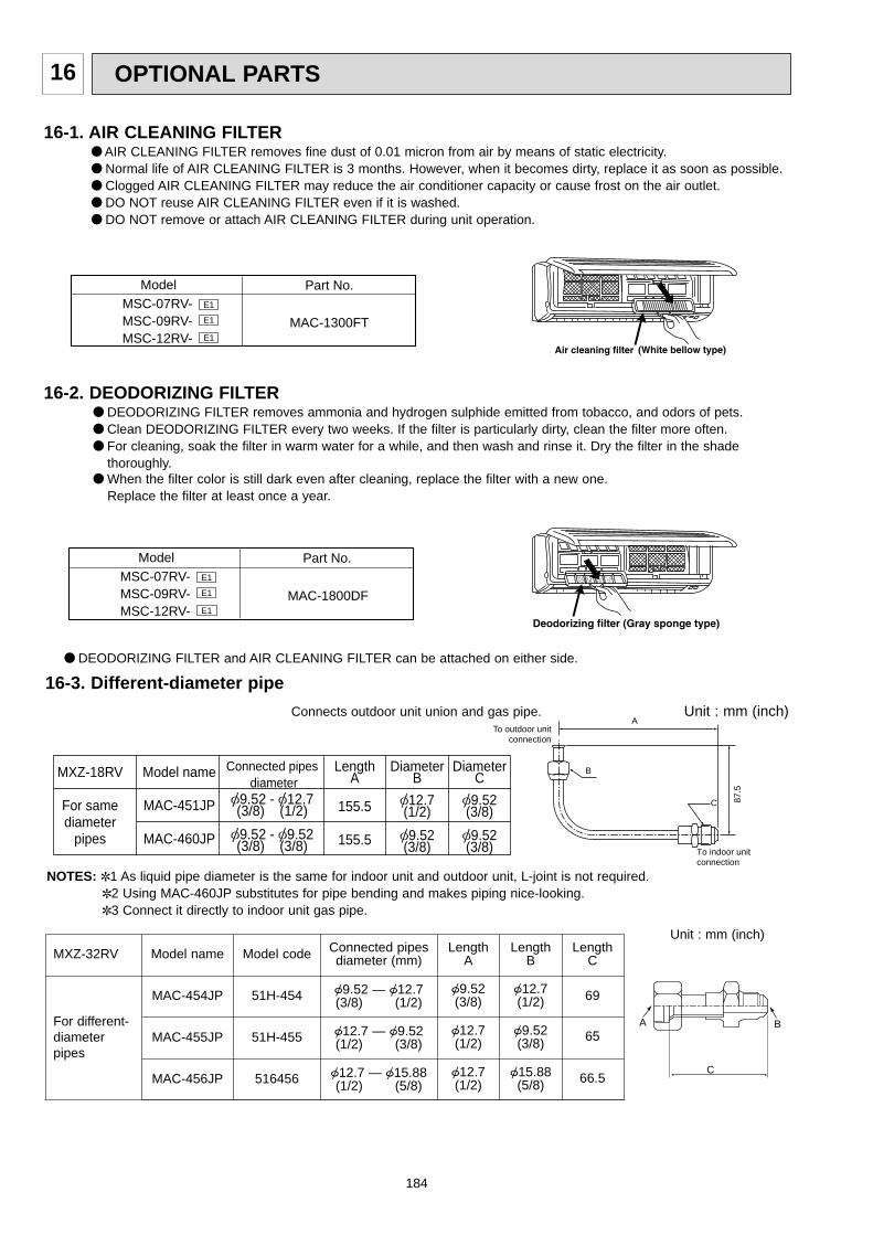
16-3. Different-diameter pipe
Unit : mm (inch)
For different-diameterpipes
MXZ-32RV
MAC-454JP
MAC-455JP
MAC-456JP
Model name
51H-454
51H-455
516456
Model code Connected pipesdiameter (mm)
LengthA
69
65
66.5
LengthB
9.52 (3/8)
12.7 (1/2)
12.7 (1/2)
12.7 (1/2)
9.52 (3/8)
15.88(5/8)
LengthC
9.52 — 12.7 (3/8) (1/2)
12.7 — 9.52 (1/2) (3/8)
12.7 — 15.88(1/2) (5/8)
BA
C
Model name
MAC-451JP
MAC-460JP
MXZ-18RV
For samediameter
pipes
Connected pipes diameter
[9.52 - [12.7(3/8) (1/2)
[9.52 - [9.52(3/8) (3/8)
LengthA
155.5
155.5
DiameterB
[12.7(1/2)
[9.52(3/8)
DiameterC
[9.52(3/8)
[9.52(3/8)
To outdoor unit connection
To indoor unit connection
A
B
C 87.5
Connects outdoor unit union and gas pipe. Unit : mm (inch)
NOTES: 1 As liquid pipe diameter is the same for indoor unit and outdoor unit, L-joint is not required. 2 Using MAC-460JP substitutes for pipe bending and makes piping nice-looking. 3 Connect it directly to indoor unit gas pipe.
184
16 OPTIONAL PARTS
16-1. AIR CLEANING FILTER AIR CLEANING FILTER removes fine dust of 0.01 micron from air by means of static electricity. Normal life of AIR CLEANING FILTER is 3 months. However, when it becomes dirty, replace it as soon as possible. Clogged AIR CLEANING FILTER may reduce the air conditioner capacity or cause frost on the air outlet. DO NOT reuse AIR CLEANING FILTER even if it is washed. DO NOT remove or attach AIR CLEANING FILTER during unit operation.
16-2. DEODORIZING FILTER DEODORIZING FILTER removes ammonia and hydrogen sulphide emitted from tobacco, and odors of pets. Clean DEODORIZING FILTER every two weeks. If the filter is particularly dirty, clean the filter more often. For cleaning, soak the filter in warm water for a while, and then wash and rinse it. Dry the filter in the shade
thoroughly. When the filter color is still dark even after cleaning, replace the filter with a new one.
Replace the filter at least once a year.
DEODORIZING FILTER and AIR CLEANING FILTER can be attached on either side.
Model Part No.
MAC-1300FTMSC-07RV-MSC-09RV-MSC-12RV-
E1
E1
E1
MAC-1800DF
Model Part No.MSC-07RV-MSC-09RV-MSC-12RV-
E1
E1
E1

185
16-4. Outlet guideChanges air discharge direction.
Applied unit Model name Model code
MXZ-18RV PAC-292SG —
MXZ-32RV MAC-855SG 51H-855
610.4534
534
386
416
51.8
150
109.4
29.2
760.
876
0.8
29.2
6.4
6.4
832
386
Punxhed hole
Punxhed hole
5 - [6
5 - [6
524
52.5
7
77
7
72
4x ø6-holes
538
524
48
13.7
10X
48 (
=48
0)
537
PAC-292SG MAC-855SG

New publication, effective Apr. 1999Specifications subject to change without notice.
CC Copyright 1999 MITSUBISHI ELECTRIC ENGINEERING CO.,LTDIssued in Apr. 1999. No.OB227 REVISED EDITION-B 245Issued in Apr. 1999. No.OB227 REVISED EDITION-A 50Issued in Dec. 1998. No.OB227 244Printed in Japan
HEAD OFFICE MITSUBISHI DENKI BLDG.MARUNOUCHI TOKYO100-8310 TELEX J24532 CABLE MELCO TOKYO