spm-a synchronizer - mega global...
TRANSCRIPT

82384R
SPM-A
Synchronizer
Installation, Operation, and Calibration Manual
Manual 82384R
!
WARNING Read this entire manual and all other publications pertaining to the work to be performed before installing, operating, or servicing this equipment. Practice all plant and safety instructions and precautions. Failure to follow instructions can cause personal injury and/or property damage. The engine, turbine, or other type of prime mover should be equipped with an overspeed (overtemperature, or overpressure, where applicable) shutdown device(s), that operates totally independently of the prime mover control device(s) to protect against runaway or damage to the engine, turbine, or other type of prime mover with possible personal injury or loss of life should the mechanical-hydraulic governor(s) or electric control(s), the actuator(s), fuel control(s), the driving mechanism(s), the linkage(s), or the controlled device(s) fail.
!
CAUTION To prevent damage to a control system that uses an alternator or battery-charging device, make sure the charging device is turned off before disconnecting the battery from the system.
!
CAUTION Electronic controls contain static-sensitive parts. Observe the following precautions to prevent damage to these parts. • Discharge body static before handling the control (with power to the control turned off, contact a grounded surface and maintain contact while handling the control). • Avoid all plastic, vinyl, and styrofoam (except antistatic versions) around printed circuit boards. • Do not touch the components or conductors on a printed circuit board with your hands or with conductive devices.
!
IMPORTANT DEFINITIONS WARNING—indicates a potentially hazardous situation which, if not avoided, could result in death or serious injury. CAUTION—indicates a potentially hazardous situation which, if not avoided, could result in damage to equipment. NOTE—provides other helpful information that does not fall under the warning or caution categories.
Woodward Governor Company reserves the right to update any portion of this publication at any time. Information provided by Woodward Governor Company is believed to be correct and reliable. However, no responsibility is assumed by Woodward Governor Company unless otherwise expressly undertaken.
© 1991 by Woodward Governor Company All Rights Reserved
Manual 82384 SPM-A Synchronizer
Woodward i
Contents CHAPTER 1. GENERAL INFORMATION .............................................................1 Regulatory Compliance Notes and Warnings ........................................................1 EMC Directive Compliance.............................................................................1 Introduction.............................................................................................................1 Description .............................................................................................................2 Theory of Operation ...............................................................................................3 Synchronizer Inputs ........................................................................................3 Operating Modes ............................................................................................3 Synchronizing the Generator ..........................................................................4 Voltage Matching............................................................................................4 CHAPTER 2. ELECTROSTATIC DISCHARGE AWARENESS ............................9 CHAPTER 3. INSTALLATION.............................................................................11 Unpacking ............................................................................................................11 Location................................................................................................................11 Installation ............................................................................................................11 Electrical Connections..........................................................................................12 Connections to the Generator ..............................................................................12 Connections to Load Sharing and Speed Controls ..............................................13 Speed Bias Output .......................................................................................13 Paralleling a Bus to a Bus.............................................................................13 Sequentially Paralleling Generator to a Bus .................................................13 Voltage Regulator Relay Output Connections ..............................................14 Breaker Closure Relay Connections ............................................................14 Class I, Division 2, Groups A, B, C, D Hazardous Locations ...............................14 CHAPTER 4. CALIBRATION AND CHECKOUT PROCEDURE ........................17 General Information..............................................................................................17 Pre-Checkout .......................................................................................................17 Dwell Time Adjustment.........................................................................................18 Test and Adjustment ............................................................................................19 Bench Test ...................................................................................................19 Dynamic Check ....................................................................................................21 Stability and Gain Adjustments.....................................................................22 Frequency Adjustment..................................................................................22 Phase Offset Adjustment..............................................................................22 Voltage Offset Adjustment............................................................................22 CHAPTER 5. SERVICE OPTIONS ......................................................................25 Product Service Options.......................................................................................25 Replacement/Exchange ...............................................................................25 Flat Rate Repair ...........................................................................................26 Flat Rate Remanufacture .............................................................................26 Returning Equipment for Repair...........................................................................26 Packing a Control .........................................................................................27 Return Authorization Number .......................................................................27 Replacement Parts...............................................................................................27 How to Contact Woodward...................................................................................27 Additional Aftermarket Product Support Services ................................................28 Technical Assistance............................................................................................30 SPM-A SYNCHRONIZER SPECIFICATIONS...........................inside back cover

SPM-A Synchronizer Manual 82384
ii Woodward
Illustrations and Tables 1-1. Control Outline Drawing..........................................................................5 1-2. System Block Diagram ...........................................................................6 1-3. Functional Block Diagram.......................................................................7 1-4. Plant Wiring Diagram..............................................................................8 3-1. Typical SPM-A Synchronizer Wiring .....................................................15 3-2. Synchronizing Bus to Bus .....................................................................16 4-1. Dwell Time Setting Switches.................................................................18

Manual 82384 SPM-A Synchronizer
Woodward 1
Chapter 1 General Information
Regulatory Compliance Notes and Warnings • The SPM-A Synchronizer is suitable for use in Ordinary Locations per CSA
and/or UL for Canada and the U.S. or non-hazardous locations only. See table below for agency listed options.
• Wiring must be in accordance with the authority having jurisdiction.
• These listings are limited only to those units bearing the UL and CSA logos. EMC Directive Compliance In accordance with the EMC Directive 89/336/EEC and its amendments, this controlling device, manufactured by the Woodward Governor Company, is applied solely as a component to be incorporated into an engine prime mover system. Woodward declares that this controlling device complies with the requirements of EN50081-2 and EN50082-2 when put into service per the installation and operating instructions outlined in the product manual.
Item Number
CSA (Canada Only)
UL (US and Canada)
EMC Directive Compliant
9905-001 X X 9905-002 X X 9905-003 X X 9905-004 X X 9905-005 X 9905-008 9905-009 9905-107 X 9907-028 X X 9907-029 X X
Introduction This manual covers the installation, theory of operation, and calibration of the SPM-A Synchronizers. The synchronizers are used in generator applications for speed and phase matching of the generator before paralleling with other generators or the utility bus. These synchronizers have adjustable dynamics to match the dynamics of the engine. Small- to medium-size diesel engines require a synchronizer with fast dynamics. Turbomachinery, large diesel, gas or gasoline engines, and steam and gas turbines require slower dynamics. Two versions of SPM-A Synchronizers are available, with or without voltage matching. Both versions are designed for a wide range of generator applications. For additional information on adjusting SPM-A Synchronizers used on lean-burn spark-ignited gas engines, see Application Note 01301.
SPM-A Synchronizer Manual 82384
2 Woodward
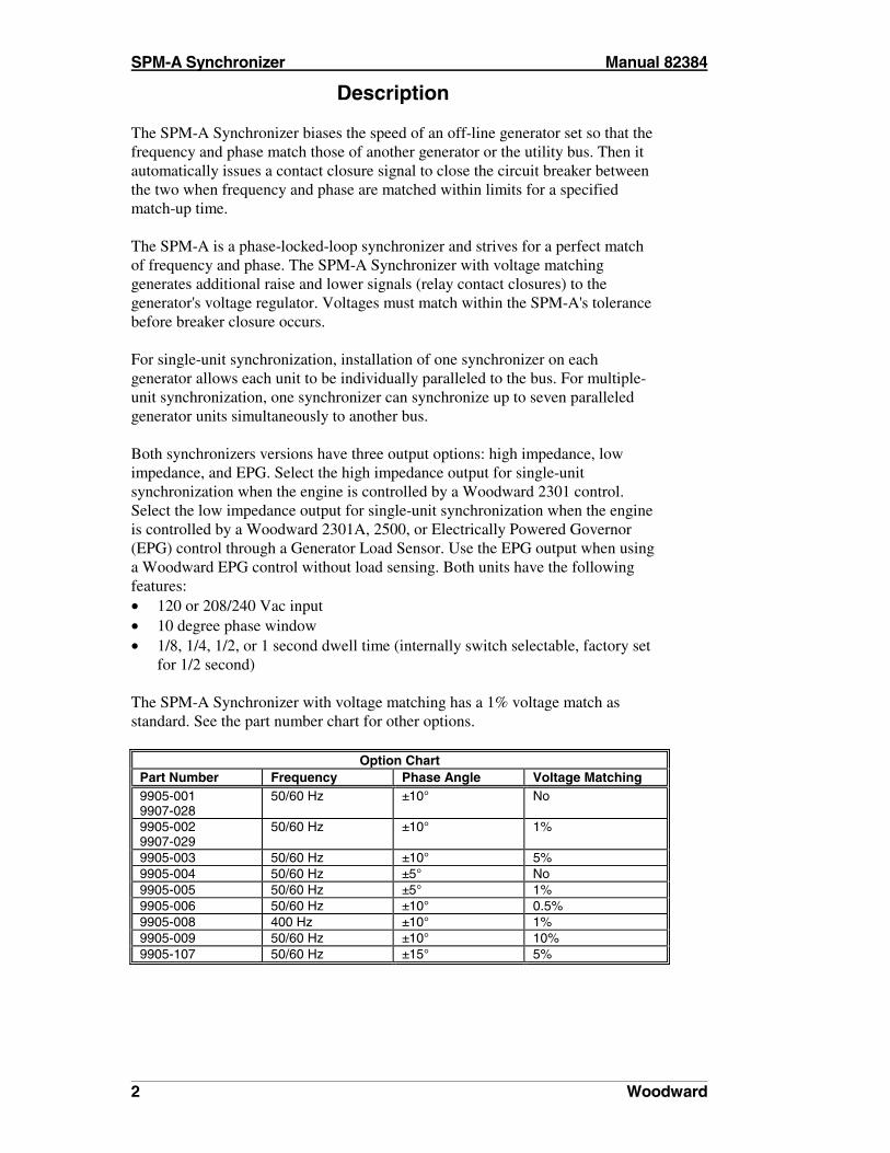
Description The SPM-A Synchronizer biases the speed of an off-line generator set so that the frequency and phase match those of another generator or the utility bus. Then it automatically issues a contact closure signal to close the circuit breaker between the two when frequency and phase are matched within limits for a specified match-up time. The SPM-A is a phase-locked-loop synchronizer and strives for a perfect match of frequency and phase. The SPM-A Synchronizer with voltage matching generates additional raise and lower signals (relay contact closures) to the generator's voltage regulator. Voltages must match within the SPM-A's tolerance before breaker closure occurs. For single-unit synchronization, installation of one synchronizer on each generator allows each unit to be individually paralleled to the bus. For multiple-unit synchronization, one synchronizer can synchronize up to seven paralleled generator units simultaneously to another bus. Both synchronizers versions have three output options: high impedance, low impedance, and EPG. Select the high impedance output for single-unit synchronization when the engine is controlled by a Woodward 2301 control. Select the low impedance output for single-unit synchronization when the engine is controlled by a Woodward 2301A, 2500, or Electrically Powered Governor (EPG) control through a Generator Load Sensor. Use the EPG output when using a Woodward EPG control without load sensing. Both units have the following features: • 120 or 208/240 Vac input • 10 degree phase window • 1/8, 1/4, 1/2, or 1 second dwell time (internally switch selectable, factory set
for 1/2 second) The SPM-A Synchronizer with voltage matching has a 1% voltage match as standard. See the part number chart for other options.
Option Chart Part Number Frequency Phase Angle Voltage Matching 9905-001 9907-028
50/60 Hz ±10° No
9905-002 9907-029
50/60 Hz ±10° 1%
9905-003 50/60 Hz ±10° 5% 9905-004 50/60 Hz ±5° No 9905-005 50/60 Hz ±5° 1% 9905-006 50/60 Hz ±10° 0.5% 9905-008 400 Hz ±10° 1% 9905-009 50/60 Hz ±10° 10% 9905-107 50/60 Hz ±15° 5%
Manual 82384 SPM-A Synchronizer
Woodward 3
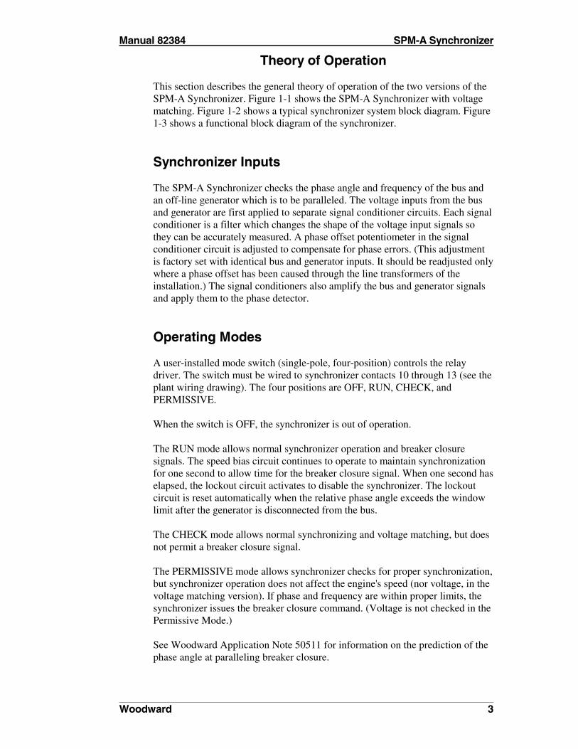
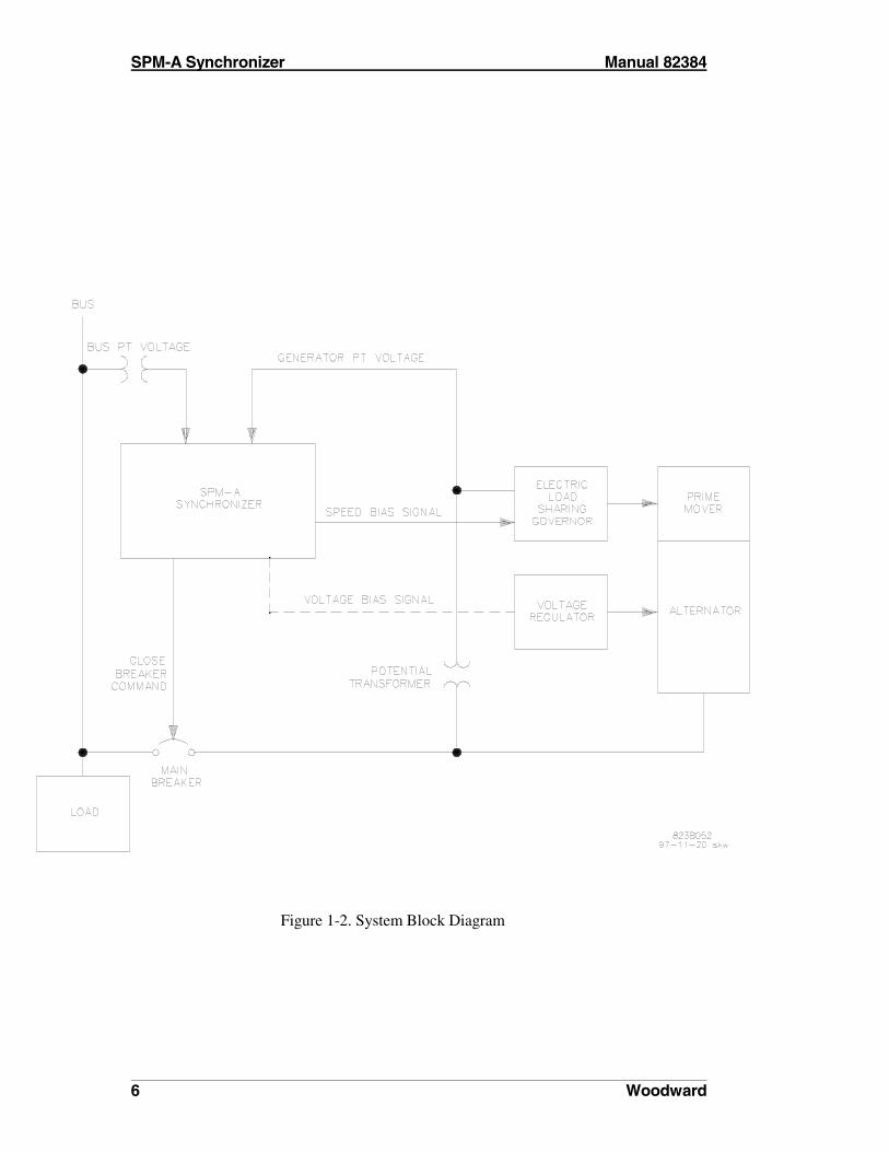
Theory of Operation This section describes the general theory of operation of the two versions of the SPM-A Synchronizer. Figure 1-1 shows the SPM-A Synchronizer with voltage matching. Figure 1-2 shows a typical synchronizer system block diagram. Figure 1-3 shows a functional block diagram of the synchronizer.
Synchronizer Inputs The SPM-A Synchronizer checks the phase angle and frequency of the bus and an off-line generator which is to be paralleled. The voltage inputs from the bus and generator are first applied to separate signal conditioner circuits. Each signal conditioner is a filter which changes the shape of the voltage input signals so they can be accurately measured. A phase offset potentiometer in the signal conditioner circuit is adjusted to compensate for phase errors. (This adjustment is factory set with identical bus and generator inputs. It should be readjusted only where a phase offset has been caused through the line transformers of the installation.) The signal conditioners also amplify the bus and generator signals and apply them to the phase detector.
Operating Modes A user-installed mode switch (single-pole, four-position) controls the relay driver. The switch must be wired to synchronizer contacts 10 through 13 (see the plant wiring drawing). The four positions are OFF, RUN, CHECK, and PERMISSIVE. When the switch is OFF, the synchronizer is out of operation. The RUN mode allows normal synchronizer operation and breaker closure signals. The speed bias circuit continues to operate to maintain synchronization for one second to allow time for the breaker closure signal. When one second has elapsed, the lockout circuit activates to disable the synchronizer. The lockout circuit is reset automatically when the relative phase angle exceeds the window limit after the generator is disconnected from the bus. The CHECK mode allows normal synchronizing and voltage matching, but does not permit a breaker closure signal. The PERMISSIVE mode allows synchronizer checks for proper synchronization, but synchronizer operation does not affect the engine's speed (nor voltage, in the voltage matching version). If phase and frequency are within proper limits, the synchronizer issues the breaker closure command. (Voltage is not checked in the Permissive Mode.) See Woodward Application Note 50511 for information on the prediction of the phase angle at paralleling breaker closure.

SPM-A Synchronizer Manual 82384
4 Woodward
Synchronizing the Generator The phase detector compares the two signals and determines any difference between the generator and bus phases. When there is a difference, the speed bias circuit sends a correction signal to the Load Sharing and Speed Control. The correction signal increases or decreases engine speed depending on whether the generator is lagging or leading the bus. Correction signal amplitude is proportional to the amount of lead or lag (phase difference). The phase window, dwell time, and breaker close circuit receive inputs from the phase detector. Using signals derived from the generator and bus inputs, the phase window circuit checks the phase angle. When the phase angle is less than the selected angle (inside the window) the dwell time circuit begins to measure the amount of time (dwell) the input signals are in phase and makes sure the signals remain in phase during breaker closure. When phase angle and dwell time requirements are correct, the breaker closing circuit sends a signal to the relay driver/inhibitor. The enable circuit gives a secondary relative phase angle check and turns on an indicator. When both the breaker closure circuit and enable circuit say the conditions have been satisfied, a signal is sent to the breaker closure relay. Then the breaker changes state for about one second. Connections for normally open contacts are provided. The synchronizer, with or without voltage matching, will not close the circuit breaker connecting the generator to a dead bus. If there is no voltage to the bus then no correction signal is sent to the Load Sharing and Speed Control and no breaker closure signal is sent to the breaker. If a dead-bus relay is used to close the breaker, the synchronizer mode switch must be in the OFF position until the synchronizer is required to synchronize and close the breaker to a live bus.
Voltage Matching The voltage comparator circuit compares the generator and bus voltages. If there is a difference, the circuits issue appropriate raise or lower commands to the voltage regulator through relay contacts (see Figures 1-3 and 1-4). A voltage offset potentiometer (factory set with identical bus and generator inputs) is included in the voltage matching circuit to compensate for internal circuit differences. This voltage offset should be readjusted only when the bus and generator are paralleled. The voltage comparator circuit also provides input to the relay driver/inhibitor. Any voltage difference between the generator and bus must be within the selected voltage range before the close breaker command may be given. The voltage matching circuit is disabled when the breaker closure signal is issued.

Manual 82384 SPM-A Synchronizer
Woodward 5
Figure 1-1. Control Outline Drawing
SPM-A Synchronizer Manual 82384
6 Woodward
Figure 1-2. System Block Diagram

Manual 82384 SPM-A Synchronizer
Woodward 7
Figure 1-3. Functional Block Diagram
SPM-A Synchronizer Manual 82384
8 Woodward
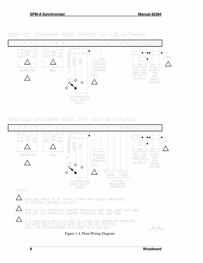
Figure 1-4. Plant Wiring Diagram
Manual 82384 SPM-A Synchronizer
Woodward 9
Chapter 2 Electrostatic Discharge Awareness
All electronic equipment is static-sensitive, some components more than others. To protect these components from static damage, you must take special precautions to minimize or eliminate electrostatic discharges. Follow these precautions when working with or near the control. 1. Before doing maintenance on the electronic control, discharge the static
electricity on your body to ground by touching and holding a grounded metal object (pipes, cabinets, equipment, etc.).
2. Avoid the build-up of static electricity on your body by not wearing
clothing made of synthetic materials. Wear cotton or cotton-blend materials as much as possible because these do not store static electric charges as much as synthetics.
3. Keep plastic, vinyl, and styrofoam materials (such as plastic or styrofoam
cups, cup holders, cigarette packages, cellophane wrappers, vinyl books or folders, plastic bottles, and plastic ash trays) away from the control, the modules, and the work area as much as possible.
4. Do not remove the printed circuit board (PCB) from the control cabinet
unless absolutely necessary. If you must remove the PCB from the control cabinet, follow these precautions:
• Do not touch any part of the PCB except the edges. • Do not touch the electrical conductors, the connectors, or the
components with conductive devices or with your hands. • When replacing a PCB, keep the new PCB in the plastic antistatic
protective bag it comes in until you are ready to install it. Immediately after removing the old PCB from the control cabinet, place it in the antistatic protective bag.

SPM-A Synchronizer Manual 82384
10 Woodward

Manual 82384 SPM-A Synchronizer
Woodward 11
Chapter 3 Installation
This chapter provides the general information for site selection, installation, and wiring of the SPM-A Synchronizer.
Unpacking Before unpacking the synchronizer, refer to the inside front cover of this manual for WARNINGS and CAUTIONS. Be careful when unpacking the synchronizer. Check for signs of damage such as bent or dented panels, scratches, loose or broken parts. If any damage is found, immediately notify the shipper.
Location When selecting a location for mounting the SPM-A Synchronizer, consider the following: • Protect the unit from direct exposure to water or to a condensation prone
environment. • The operating range of the synchronizer is –45 to +70 °C (–49 to +158 °F).
For best operation, maintain the ambient air temperature between +10 and +30 °C (+50 and +86 °F).
• Provide adequate ventilation for cooling. Shield the synchronizer from radiant heat sources.
• Do not install the synchronizer near high-voltage high-current devices. • Allow adequate space in front of the unit for servicing. • Do not install the synchronizer where objects can be dropped on it or its
terminals. • Ground the synchronizer for proper shielding.
Installation Select a mounting location for the SPM-A Synchronizer (see considerations above). Locate and drill four holes for mounting hardware (not furnished; see Figure 1-1 for locations). Tap the holes for machine screws or bolts. Install the synchronizer and secure with the mounting hardware.
SPM-A Synchronizer Manual 82384
12 Woodward
Electrical Connections The following instructions and wiring diagrams illustrate typical wiring connections. For applications not shown in Figures 3-1 and 3-2, refer to the plant wiring diagram (Figure 1-4) or contact Woodward for assistance. Connect the synchronizer terminals as shown in Figure 1-4. When making the connections, observe the following: • Make all connections using insulated terminals. • Use 0.5 mm2 (20 AWG) or larger stranded, twisted shielded wire. • Make sure that all wires shown as shielded on the plant wiring diagram, are
shielded. • Do not place shielded wires in the same cable conduits with high-voltage or
high-current carrying cables. • Do not connect the cable shields to any external grounds. The shields are
grounded at the control end only. • Make sure that cable shields are carried through all intermediate terminal
blocks from signal source to signal termination. • Do not subject any wiring to temperatures above 100 °C (212 °F). • Avoid kinks or sharp bends in the wiring. • Make sure that all connections are tight. For additional wiring information, see Woodward Manual 25070, Electric Governor Installation Guide. Install and wire the other units and actuators in your system using instructions in applicable manuals.
Connections to the Generator The synchronizer is powered by voltage supply connections to the generator potential transformers (PTs). It uses a standard 120 Vac or 208/230 Vac, 50/60 Hz input. The synchronizer can use the same voltage connections to the generator PTs as the electronic governor's load sensor. Power consumption of the synchronizer is 5 W maximum. 1. Connect the generator PT neutral to synchronizer terminal 5 (Figure 2-1). 2. Connect one phase of the generator PT (usually phase A) to synchronizer
terminal 2. 3. Connect the same phase from the bus PT to synchronizer terminal 6. 4. Connect bus neutral to terminal 9.
Manual 82384 SPM-A Synchronizer
Woodward 13
Connections to Load Sharing and Speed Control
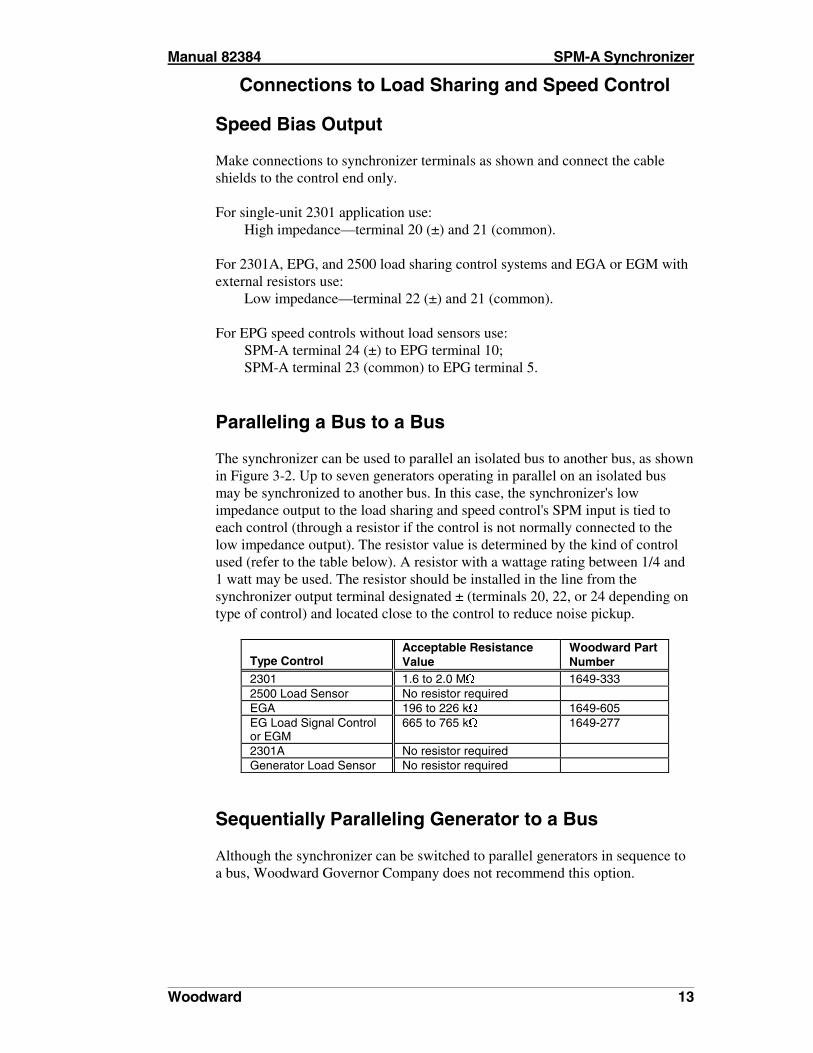
Speed Bias Output Make connections to synchronizer terminals as shown and connect the cable shields to the control end only. For single-unit 2301 application use: High impedance—terminal 20 (±) and 21 (common). For 2301A, EPG, and 2500 load sharing control systems and EGA or EGM with external resistors use: Low impedance—terminal 22 (±) and 21 (common). For EPG speed controls without load sensors use: SPM-A terminal 24 (±) to EPG terminal 10; SPM-A terminal 23 (common) to EPG terminal 5.
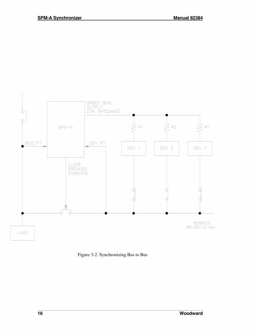
Paralleling a Bus to a Bus The synchronizer can be used to parallel an isolated bus to another bus, as shown in Figure 3-2. Up to seven generators operating in parallel on an isolated bus may be synchronized to another bus. In this case, the synchronizer's low impedance output to the load sharing and speed control's SPM input is tied to each control (through a resistor if the control is not normally connected to the low impedance output). The resistor value is determined by the kind of control used (refer to the table below). A resistor with a wattage rating between 1/4 and 1 watt may be used. The resistor should be installed in the line from the synchronizer output terminal designated ± (terminals 20, 22, or 24 depending on type of control) and located close to the control to reduce noise pickup.
Type Control
Acceptable Resistance Value
Woodward Part Number
2301 1.6 to 2.0 M( 1649-333 2500 Load Sensor No resistor required EGA 196 to 226 k( 1649-605 EG Load Signal Control or EGM
665 to 765 k( 1649-277
2301A No resistor required Generator Load Sensor No resistor required
Sequentially Paralleling Generator to a Bus Although the synchronizer can be switched to parallel generators in sequence to a bus, Woodward Governor Company does not recommend this option.

SPM-A Synchronizer Manual 82384
14 Woodward
Voltage Regulator Relay Output Connections Make the connections as required to terminals 16 through 19 of the synchronizer. Terminals are shown in Figure 1-4, which give normally open contacts for operation to the voltage regulator. The ratings for the voltage raise and lower relay contacts are: Resistive Loads: 10 A at 28 Vdc 3 A at 120 Vac, 50/60 Hz Inductive Loads: 6 A at 28 Vdc 2 A at 120 Vac, 50/60 Hz
Breaker Closure Relay Connections Make connections from the breaker closure relay to terminals 14 and 15 of the synchronizer. These terminals, shown in Figure 1-4, give normally open contacts. The ratings for the breaker closure relay contacts are: Resistive Loads: 10 A at 28 Vdc 3 A at 120 Vac, 50/60 Hz Inductive Loads: 6 A at 28 Vdc 2 A at 120 Vac, 50/60 Hz
� NOTE If a dead-bus relay is used to close the breaker, the synchronizer mode switch must be in the OFF position until the synchronizer is required to synchronize and close the breaker to a live bus.

Manual 82384 SPM-A Synchronizer
Woodward 15
Figure 3-1. Typical SPM-A Synchronizer Wiring
SPM-A Synchronizer Manual 82384
16 Woodward
Figure 3-2. Synchronizing Bus to Bus
Manual 82384 SPM-A Synchronizer
Woodward 17
Chapter 4 Calibration and Checkout Procedure
This chapter covers the checkout and calibration of the SPM-A Synchronizer. These procedures must be followed in sequence for proper calibration of the synchronizer. Notes in the text indicate when procedures are different for each SPM-A model.
� NOTE Before attempting to calibrate the synchronizer, read Woodward Manual 82715, Guide for Handling and Protection of Electronic Controls, Printed Circuit Boards, and Modules.
General Information Read and follow these instructions carefully when checking or calibrating the synchronizer: • Observe precautions for handling static-sensitive devices (see Chapter 2). • Use battery-operated test equipment whenever possible. • Isolate the test equipment from all grounds, including the chassis. • Use a digital multimeter (DMM) for all measurements and a volt-ohmmeter
(VOM) when checking indicators and relay contacts. • Apply power to the synchronizer before applying power to any test
equipment connected to it. • Make sure that the wiring connections have been made in accordance with
the plant wiring diagram (Figure 1-4) and that the connections are tight. • The values given in this procedure are the values used by the factory for
calibration of the new synchronizer. Be sure that no specification changes or modifications have been made that will change these values.
Pre-Checkout All other units in the engine control system must be adjusted and working correctly before operating the synchronizer. While operating the engine to make adjustments on the other units, the synchronizer mode switch (user supplied) must be in the OFF position.
SPM-A Synchronizer Manual 82384
18 Woodward
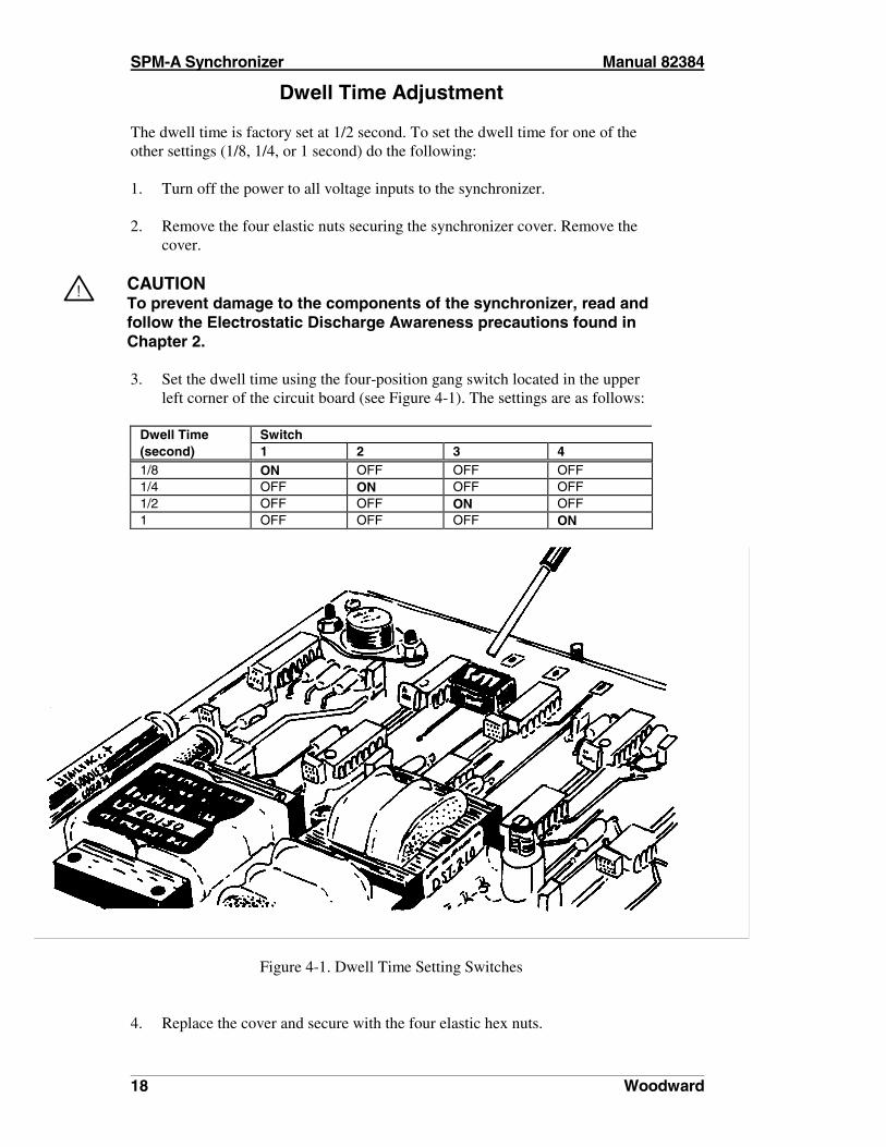
Dwell Time Adjustment The dwell time is factory set at 1/2 second. To set the dwell time for one of the other settings (1/8, 1/4, or 1 second) do the following: 1. Turn off the power to all voltage inputs to the synchronizer. 2. Remove the four elastic nuts securing the synchronizer cover. Remove the
cover.
!
CAUTION To prevent damage to the components of the synchronizer, read and follow the Electrostatic Discharge Awareness precautions found in Chapter 2. 3. Set the dwell time using the four-position gang switch located in the upper
left corner of the circuit board (see Figure 4-1). The settings are as follows:
Dwell Time Switch (second) 1 2 3 4 1/8 ON OFF OFF OFF 1/4 OFF ON OFF OFF 1/2 OFF OFF ON OFF 1 OFF OFF OFF ON
Figure 4-1. Dwell Time Setting Switches
4. Replace the cover and secure with the four elastic hex nuts.
Manual 82384 SPM-A Synchronizer
Woodward 19
Test and Adjustment Bench Test A simple bench test may be done prior to installing the synchronizer. No adjustments can be made as a result of this test. The bench test only provides an indication of proper basic operation.
!
WARNING The following procedures uses high voltage power for testing. Personal injury or death can occur if normal safety precautions are not used when working with high voltage. 1. Connect a utility power source (wall outlet) of 115 Vac, 60 Hz through
single-pole single-throw switches to the BUS and GENERATOR input terminals. Leave the switches turned off.
2. Connect a mode switch, single-pole four-throw, to terminals 10 through 13
as shown on the diagram on the synchronizer. Place the mode switch in the OFF position.
3. This test checks for breaker closure with matching live bus and generator
inputs. a. Turn on both the BUS and GENERATOR power switches. The
ENABLE indicator will illuminate and the BREAKER CLOSURE contact terminal will be open.
b. Place the mode switch in the RUN position. The ENABLE indicator
will remain illuminated and the BREAKER CLOSURE contacts will close for 1 second then open.
c. Place the mode switch in the OFF position. The ENABLE indicator
will remain illuminated and the BREAKER CLOSURE contacts will be open.
d. Turn off the power switches. 4. This test checks the power up in run mode interlock protection. a. Place the mode switch in the RUN position. b. Turn on both the BUS and GENERATOR power switches. The
ENABLE indicator will be illuminated and the BREAKER CLOSURE contacts will be open.
c. Turn off the power switches.

SPM-A Synchronizer Manual 82384
20 Woodward
5. This test checks for live bus to dead generator breaker closure interlock. a. Place the mode switch in the OFF position. b. Turn on the power switch to the BUS. Leave the GENERATOR power
switch off. c. The ENABLE indicator will be off and the BREAKER CLOSURE
contacts will be open. d. Place the mode switch in the RUN position. The ENABLE indicator
will be off, and the BREAKER CLOSURE contacts will be open. e. Place the mode switch in the OFF position. The ENABLE indicator
will be off, and the BREAKER CLOSURE contacts will be open. f. Turn the BUS power switch off, then turn it on. g. Turn the GENERATOR power switch on. h. With the mode switch in the OFF position, the ENABLE indicator will
be illuminated and the BREAKER CLOSURE contacts will be open. i. Place the mode switch in the RUN position. The ENABLE indicator
will be illuminated and the BREAKER CLOSURE contacts will be closed for 1 second then open.
j. Place the mode switch in the OFF position. Turn off the BUS and
GENERATOR power switches. 6. This test checks the live generator to dead bus breaker closure interlock. a. Place the mode switch in the OFF position. b. Turn on the GENERATOR power switch, leave the BUS power switch
off. c. With the mode switch in the OFF position, the ENABLE indicator will
be off and the BREAKER CLOSURE contacts will be open. d. Place the mode switch in the RUN position. The ENABLE indicator
will be off and the BREAKER CLOSURE contacts will be open. e. Place the mode switch in the OFF position. f. Turn off the GENERATOR power switch. g. Turn on the BUS power switch and then turn on the GENERATOR
power switch.
Manual 82384 SPM-A Synchronizer
Woodward 21
h. With the mode switch in the OFF position, the ENABLE indicator will be illuminated and the BREAKER CLOSURE contacts will be open.
i. Place the mode switch in the RUN position. The ENABLE indicator
will be illuminated and the BREAKER CLOSURE contacts will close for 1 second then open.
j. Place the mode switch in the OFF position. k. Turn off the BUS and GENERATOR power switches.
Dynamic Check The best way to test and adjust the synchronizer is to operate it while in the CHECK mode. 1. Place the mode switch (user supplied) in the OFF position for starting. 2. Apply power to the electronic governor and start the engine according to the
manufacturer's instructions.
!
WARNING TO PROTECT AGAINST POSSIBLE PERSONAL INJURY, LOSS OF LIFE, and/or PROPERTY DAMAGE WHEN STARTING THE ENGINE, BE PREPARED TO MAKE AN EMERGENCY SHUTDOWN to protect against runaway or overspeed should the mechanical-hydraulic governor(s), or electric control(s), the actuator(s), fuel control(s), the driving mechanism(s), the linkage(s), or the controlled device(s) fail. 3. Go to rated speed for the specified generator frequency. 4. Place the mode switch in the CHECK position. 5. Watch the panel meter to make sure that the synchronizer is matching
frequency and phase (and, in the voltage matching model, the voltage of the generator to the bus). When these are matched within the limits, the ENABLE indicator will illuminate.
� NOTE The phase offset potentiometer (and on the voltage match model, the voltage match potentiometer) are calibrated at the factory. They do not normally require adjustment by the user for operation. If the panel meters show incorrect phase or voltage matching, verify that they are calibrated and adjust if necessary.
SPM-A Synchronizer Manual 82384
22 Woodward
Stability and Gain Adjustments Place the mode switch in the OFF position. Adjust the generator approximately 1 Hz higher than the specified frequency. When the phase angle reaches 180 degrees, place the mode switch in the CHECK position. Watch the synchronizer's control action. Adjust the gain potentiometer for faster response and the stability potentiometer for minimum overshoot and settling time at 0 degrees phase angle. Return the generator to correct frequency.
Frequency Adjustment To set an oncoming generator frequency to the system being paralleled, place the mode switch in the CHECK mode. Measure the synchronizer output with a high-impedance voltmeter. Adjust the rated speed potentiometer of the oncoming unit for 0 (zero) output voltage from the synchronizer. An alternate method, where the system includes a synchroscope, is to leave the synchronizer in the off position and adjust the rated speed potentiometer of the oncoming unit until the synchroscope stops. The closer the frequencies are set, the better the load sharing action.
Phase Offset Adjustment If the synchroscope steadies at other than 0 (zero) degrees (in the CHECK mode), the phase offset potentiometer may need adjustment. 1. Note the potentiometer position before changing the setting. 2. Turn the potentiometer as necessary to center the indicator of the
synchroscope.
Voltage Offset Adjustment (Voltage Matching Model Only) If the panel meters show that the generator voltage is different from that of the bus, the voltage offset potentiometer may need adjustment. Make sure that the panel meters are accurate, calibrated, and at operating temperature. Most panel meters are accurate to ±3% and are not temperature compensated. 1. Note the potentiometer position before changing the setting. 2. Disconnect all wiring from the voltage matching terminals (16 through 19)
to the voltage regulator. 3. Operate the synchronizer in the CHECK mode.
Manual 82384 SPM-A Synchronizer
Woodward 23
4. Attach the leads of an ohmmeter to synchronizer terminals 16 and 17. 5. Turn the voltage offset potentiometer counterclockwise and make a note of
its setting when the ohmmeter first indicates a relay contact closure (the voltage matching circuit is issuing a raise command to the voltage regulator).
6. Repeat the procedure with the ohmmeter leads on terminals 18 and 19
(lower command). Turn the potentiometer clockwise and note the setting. 7. Adjust the voltage offset potentiometer to the correct setting, halfway
between the two settings.
� NOTE If the voltage offset potentiometer is misadjusted, the generator's voltage regulator may drive in the opposite direction from what is needed. The voltage offset potentiometer sets the voltage match window. The potentiometer must be adjusted so that the line voltage is contained within the window. Otherwise, the voltage regulator on the generator will be run in the opposite direction of the voltage mismatch. This will take the generator off line on reverse current. 8. Attach the original wiring to the voltage matching terminals.
� NOTE When the breaker close signal is initiated, the voltage match circuit is disabled. For operation of the synchronizer once it has been adjusted and tested, set the mode switch to the RUN or PERMISSIVE position. The ENABLE indicator will illuminate while the phase (and voltage in the voltage matching model) are near breaker closure limits. After the generator set is paralleled, under control of the synchronizer, the synchronizer is disabled.

SPM-A Synchronizer Manual 82384
24 Woodward

Manual 82384 SPM-A Synchronizer
Woodward 25
Chapter 5 Service Options
Product Service Options The following are the factory options available for the service of Woodward equipment under Woodward’s standard Product and Service Warranty (25222), in effect at the time the product is sold from Woodward or the service is performed: • Replacement/Exchange (24-hour service) • Flat Rate Repair • Flat Rate Remanufacture If you are experiencing problems with installation or unsatisfactory performance of an installed system, the following options are available: • Consult the troubleshooting guide in the manual. • Contact Woodward technical assistance (see “How to Contact Woodward”
later in this chapter) and discuss your problem. In most cases, your problem can be resolved over the phone. If not, you can select which course of action you wish to pursue based on the available services listed in this section.
Replacement/Exchange Replacement/Exchange is a premium program designed for the user who is in need of immediate service. It allows you to request and receive a like-new replacement unit in minimum time (usually within 24 hours of the request), providing a suitable unit is available at the time of the request, thereby minimizing costly downtime. This is also a Flat Rate structured program and includes the full standard Woodward product warranty, pursuant to Woodward’s Product and Service Warranty (25222). This option allows you to call in advance of a scheduled outage or an unexpected outage and request a replacement control unit. If the unit is available at the time of the call, it can usually be shipped out within 24 hours. You replace your field control unit with the like-new replacement and return the field unit to the Woodward facility as explained later in this chapter. Charges for the Replacement/Exchange service are based on a flat rate plus shipping expenses. You are invoiced the flat rate replacement/exchange charge plus a core charge at the time the replacement unit is shipped. If the core (field unit) is returned to Woodward within 60 days, Woodward will issue a credit for the core charge. [The core charge is the average difference between the flat rate replacement/exchange charge and the current list price of a new unit.]
SPM-A Synchronizer Manual 82384
26 Woodward
Return Shipment Authorization Label. To ensure prompt receipt of the core, and avoid additional charges, the package must be properly marked. A return authorization label is included with every Replacement/Exchange unit that leaves Woodward. The core should be repackaged and the return authorization label affixed to the outside of the package. Without the authorization label, receipt of the returned core could be delayed and cause additional charges to be applied.
Flat Rate Repair Flat Rate Repair is available for the majority of standard products in the field. This program offers you repair service for your products with the advantage of knowing in advance what the cost will be. All repair work carries the standard Woodward service warranty, pursuant to Woodward’s Product and Service Warranty (25222) on replaced parts and labor.
Flat Rate Remanufacture Flat Rate Remanufacture is very similar to the Flat Rate Repair option with the exception that the unit will be returned to you in “like new” condition and carry with it the full standard Woodward product warranty, pursuant to Woodward’s Product and Service Warranty (25222). This option is applicable to mechanical products only.
Returning Equipment for Repair If a control (or any part of an electronic control) is to be returned to Woodward for repair, please contact Woodward in advance to obtain a Return Authorization Number. When shipping the item(s), attach a tag with the following information: • name and location where the control is installed; • name and phone number of contact person; • complete Woodward part number(s) and serial number(s); • description of the problem; • instructions describing the desired type of repair.
!
CAUTION To prevent damage to electronic components caused by improper handling, read and observe the precautions in Woodward manual 82715, Guide for Handling and Protection of Electronic Controls, Printed Circuit Boards, and Modules.
Manual 82384 SPM-A Synchronizer
Woodward 27
Packing a Control Use the following materials when returning a complete control: • protective caps on any connectors; • antistatic protective bags on all electronic modules; • packing materials that will not damage the surface of the unit; • at least 100 mm (4 inches) of tightly packed, industry-approved packing
material; • a packing carton with double walls; • a strong tape around the outside of the carton for increased strength.
Return Authorization Number When returning equipment to Woodward, please telephone and ask for the Customer Service Department [(1)(800) 835-5182 in North America or (1)(970) 498-5811]. They will help expedite the processing of your order through our distributors or local service facility. To expedite the repair process, contact Woodward in advance to obtain a Return Authorization Number, and arrange for issue of a purchase order for the item(s) to be repaired. No work can be started until a purchase order is received.
� NOTE We highly recommend you make arrangement in advance for return shipments. Contact a Woodward customer service representative at (1)(800) 835-5182 in North America or (1)(970) 498-5811 for instructions and for a Return Authorization Number.
Replacement Parts When ordering replacement parts for controls, include the following information: • the part number(s) (XXXX-XXX) that is on the enclosure nameplate; • the unit serial number, which is also on the nameplate.
How to Contact Woodward In North America use the following address when shipping or corresponding: Woodward Governor Company PO Box 1519 1000 East Drake Rd Fort Collins CO 80522-1519, USA TELEPHONE: (1)(970) 498-5811 (24 hours a day) TOLL-FREE PHONE (in North America): (1)(800) 835-5182 FAX: (1)(970) 498-3058

SPM-A Synchronizer Manual 82384
28 Woodward
For assistance outside North America, call one of the following international Woodward facilities to obtain the address and phone number of the facility nearest your location where you will be able to get information and service. FACILITY PHONE NUMBER Australia (61)(2) 9758 2322 England (44)(118) 975 2727 India (91)(129) 230419 Japan (81)(476) 93-4661 The Netherlands (31)(23) 56 61111 You can also contact the Woodward Customer Service Department or consult our worldwide directory on Woodward’s Internet website (http://www.woodward.com) for the name of your nearest Woodward distributor or service facility:
Additional Aftermarket Product Support Services Woodward Aftermarket Services offers the following after-sale support for all Woodward products: • Customer Training • Technical Assistance • Field Service • Specialized Services Customer Training is offered at our facility in Loveland, Colorado, or at your site. This training, conducted by experienced trainers, will assure that customer personnel will be able to maintain system reliability and availability. For information concerning training available, call the number above and ask for customer training. Technical Assistance is available using the Woodward toll-free number. The Aftermarket application engineering group is available to assist customers with technical questions or problem solving during normal business hours or as emergency support 24 hours a day. This group can also provide engineering support for changes or enhancements after the commissioning of your system. For technical engineering assistance, call the number above and ask for technical assistance.
Manual 82384 SPM-A Synchronizer
Woodward 29
Field Service engineers are dispatched from the Woodward facility in Colorado, or from one of many regional or worldwide offices located near the customer to provide prompt response. Woodward field engineers are experienced and are continually updated on all Woodward products as well as much of the non-Woodward equipment they interface with. The field engineers ensure that all documentation is updated, and all field engineers are well informed as to new problems which might arise. Woodward field service engineers are on-call 24 hours a day. Call the number above and ask for field service. Specialized Services can be tailored to your specific needs. These services can be based on a particular aspect of a single service or a combination of services and are covered under one low-cost service contract. A contract may be for regularly scheduled training courses or possibly to have a field engineer visit your site at pre-determined intervals to provide a system analysis, verify proper operation, and make recommendations for maintenance improvements, enhancements, or other needs. These contracts are usually custom-designed and structured to allow ultimate flexibility, thereby allowing you to plan and budget more accurately. For more details, contact the Woodward sales representative, or call the number above and ask for sales support to discuss specific needs.
SPM-A Synchronizer Manual 82384
30 Woodward
Technical Assistance If you need to telephone for technical assistance, you will need to provide the following information. Please write it down here before phoning:
General Your Name Site Location Phone Number Fax Number
Prime Mover Information Engine/Turbine Model Number Manufacturer Number of Cylinders (if applicable) Type of Fuel (gas, gaseous, steam, etc) Rating Application
Governor Information Please list all Woodward governors, actuators, and electronic controls in your system:
Woodward Part Number and Revision Letter Control Description or Governor Type Serial Number Woodward Part Number and Revision Letter Control Description or Governor Type Serial Number Woodward Part Number and Revision Letter Control Description or Governor Type Serial Number If you have an electronic or programmable control, please have the adjustment setting positions or the menu settings written down and with you at the time of the call.
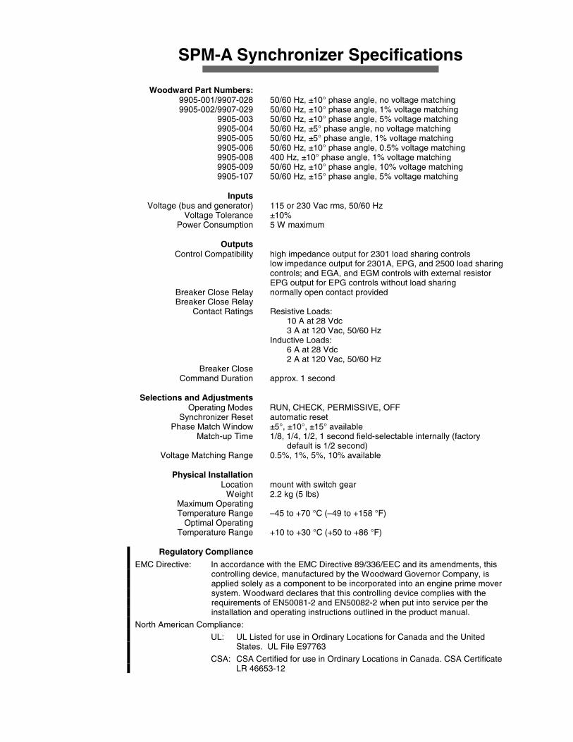
SPM-A Synchronizer Specifications Woodward Part Numbers: 9905-001/9907-028 50/60 Hz, ±10° phase angle, no voltage matching 9905-002/9907-029 50/60 Hz, ±10° phase angle, 1% voltage matching 9905-003 50/60 Hz, ±10° phase angle, 5% voltage matching 9905-004 50/60 Hz, ±5° phase angle, no voltage matching 9905-005 50/60 Hz, ±5° phase angle, 1% voltage matching 9905-006 50/60 Hz, ±10° phase angle, 0.5% voltage matching 9905-008 400 Hz, ±10° phase angle, 1% voltage matching 9905-009 50/60 Hz, ±10° phase angle, 10% voltage matching 9905-107 50/60 Hz, ±15° phase angle, 5% voltage matching Inputs Voltage (bus and generator) 115 or 230 Vac rms, 50/60 Hz Voltage Tolerance ±10% Power Consumption 5 W maximum Outputs Control Compatibility high impedance output for 2301 load sharing controls
low impedance output for 2301A, EPG, and 2500 load sharing controls; and EGA, and EGM controls with external resistor
EPG output for EPG controls without load sharing Breaker Close Relay normally open contact provided Breaker Close Relay Contact Ratings Resistive Loads: 10 A at 28 Vdc 3 A at 120 Vac, 50/60 Hz Inductive Loads: 6 A at 28 Vdc 2 A at 120 Vac, 50/60 Hz Breaker Close Command Duration approx. 1 second Selections and Adjustments Operating Modes RUN, CHECK, PERMISSIVE, OFF Synchronizer Reset automatic reset Phase Match Window ±5°, ±10°, ±15° available Match-up Time 1/8, 1/4, 1/2, 1 second field-selectable internally (factory
default is 1/2 second) Voltage Matching Range 0.5%, 1%, 5%, 10% available Physical Installation Location mount with switch gear Weight 2.2 kg (5 lbs) Maximum Operating Temperature Range –45 to +70 °C (–49 to +158 °F) Optimal Operating Temperature Range +10 to +30 °C (+50 to +86 °F) Regulatory Compliance
EMC Directive: In accordance with the EMC Directive 89/336/EEC and its amendments, this controlling device, manufactured by the Woodward Governor Company, is applied solely as a component to be incorporated into an engine prime mover system. Woodward declares that this controlling device complies with the requirements of EN50081-2 and EN50082-2 when put into service per the installation and operating instructions outlined in the product manual.
North American Compliance:
UL: UL Listed for use in Ordinary Locations for Canada and the United States. UL File E97763
CSA: CSA Certified for use in Ordinary Locations in Canada. CSA Certificate LR 46653-12

We appreciate your comments about the content of our publications. Please send comments to: Woodward Governor Company Attention: Technical Publications PO Box 1519 Fort Collins CO 80522-1519, USA Please include the manual number from the front cover of this publication.
Woodward Governor Company/Industrial Controls PO Box 1519, Fort Collins CO 80522-1519, USA
1000 East Drake Road, Fort Collins CO 80525, USA Phone (1)(970) 482-5811 • Fax (1)(970) 498-3058
E-mail and World Wide Web Home Page—http://www.woodward.com
Woodward has company-owned plants, subsidiaries, and branches, as well as authorized distributors and other authorized service and sales facilities throughout the world.
Complete address/phone/fax/e-mail information for all locations is available on our website.
01/1/F
Registered Firm
ISO 9001:1994/Q9001-1994 Certificate QSR-36