spot - abb ltd spot light beam can be mounted using a variety of brackets, posts and mirrors. refer...
TRANSCRIPT

ABB AB / Jokab Safety Varlabergsvägen 11, SE-434 39, Sweden www.abb.com/jokabsafety
Original instructions
Spot Safety light beam

2TLC172178M0201, rev. E 2 www.abb.com/jokabsafety 2013-02-28
Read and understand this document Please read and understand this document before using the products. Please consult your ABB/JOKAB SAFETY representative if you have any questions or comments.
WARRANTY
ABB/JOKAB SAFETY’s exclusive warranty is that the products are free from defects in materials and workmanship for a period of one year (or other period if specified) from date of sale by ABB/JOKAB SAFETY.
ABB/JOKAB SAFETY MAKES NO WARRANTY OR REPRESENTATION, EXPRESSED OR IMPLIED, REGARDING NON-INFRINGEMENT, MERCHANTABILITY, OR FITNESS FOR PARTICULAR PURPOSE OF THE PRODUCTS, ANY BUYER OR USER ACKNOWLEDGES THAT THE BUYER OR USER ALONE HAS DETERMINED THAT THE PRODUCTS WILL SUITABLY MEET THE REQUIREMENTS OR THEIR INTENDED USE. ABB/JOKAB SAFETY DISCLAIMS ALL OTHER WARRANTIES, EXPRESSED OR IMPLIED.
LIMITATIONS OF LIABILITY
ABB/JOKAB SAFETY SHALL NOT BE RESPONSIBLE FOR SPECIAL, INDIRECT, OR CONSEQUENTIAL DAMAGES, LOSS OF PROFITS OR COMMERCIAL LOSS IN ANY WAY CONNECTED WITH THE PRODUCTS, WHETHER SUCH CLAIM IS BASED ON CONTRACT, WARRANTY, NEGLIGENCE, OR STRICT LIABILITY.
In no event shall responsibility of ABB/JOKAB SAFETY for any act exceed the individual price of the product on which liability asserted.
IN NO EVENT SHALL ABB/JOKAB SAFETY BE RESPONSIBLE FOR WARRANTY, REPAIR, OR OTHER CLAIMS REGARDING THE PRODUCTS UNLESS ABB/JOKAB SAFETY’S ANALYSIS CONFIRMS THAT THE PRODUCTS WERE PROPERLY HANDLED, STORED, INSTALLED, AND MAINTAINED AND NOT SUBJECT TO ABUSE, MISUSE, OR INAPPROPRIATE MODIFICATION OR REPAIR.
SUITABILITY FOR USE
ABB/JOKAB SAFETY shall not be responsible for conformity with any standards, codes, or regulations that apply to the combination of products in the customer’s application or use of the product. At the customer’s request, ABB/JOKAB SAFETY will provide applicable third party certification documents identifying ratings and limitations of use that apply to the products. This information by itself is not sufficient for a complete determination of the suitability of the products in combination with the end product, machine, system, or other application or use.
The following are some examples of applications for which particular attention must be given. This is not intended to be an exhaustive list of all possible uses of the products, nor is it intended to imply that the uses listed may be suitable for the products:
Outdoor use, uses involving potential chemical contamination or electrical interference, or conditions or uses not described in this document.
Nuclear energy control systems, combustion systems, railroad systems, aviation systems, medical equipment, amusement machines, vehicles, and installations subject to separate industry or government regulations.
Systems, machines, and equipment that could present a risk to life or property.
Please know and observe all prohibitions of use applicable to the products.
NEVER USE THE PRODUCTS FOR AN APPLICATION INVOLVING SERIOUS RISK TO LIFE OR PROPERTY WITHOUT ENSURING THAT THE SYSTEM AS A WHOLE HAS BEEN DESIGNED TO ADDRESS THE RISKS, AND THAT THE ABB/JOKAB SAFETY PRODUCT IS PROPERLY RATED AND INSTALLED FOR THE INTENDED USE WITHIN THE OVERALL EQUIPMENT OR SYSTEM.
PERFORMANCE DATA
While every effort has been taken to ensure the accuracy of the information contained in this manual ABB/JOKAB SAFETY cannot accept responsibility for errors or omissions and reserves the right to make changes and improvements without notice. Performance data given in this document is provided as a guide for the user in determining suitability and does not constitute a warranty. It may represent the result of ABB/JOKAB SAFETY’S test conditions, and the users must correlate it to actual application requirements. Actual performance is subject to the ABB/JOKAB SAFETY Warranty and Limitations of Liability.

2TLC172178M0201, rev. D 3 www.abb.com/ 2013-02-28
Table of Contents 1 Introduction ......................................................................................................................................... 4
Scope ........................................................................................................................................................................ 4
Audience ................................................................................................................................................................... 4
Prerequisites ............................................................................................................................................................. 4
Special notes ............................................................................................................................................................ 4
2 Overview .............................................................................................................................................. 5
General description ................................................................................................................................................... 5
Intended use ............................................................................................................................................................. 5
Safety regulations ..................................................................................................................................................... 5
Function description .................................................................................................................................................. 6
3 Connections ........................................................................................................................................ 7
Connection examples ............................................................................................................................................... 7
4 Installation and maintenance ............................................................................................................. 9
Mounting and alignment ........................................................................................................................................... 9
Positioning precautions ........................................................................................................................................... 11
Installation precautions ........................................................................................................................................... 14
Maintenance ........................................................................................................................................................... 14
In case of functional problems ................................................................................................................................ 14
5 Operation ........................................................................................................................................... 15
LED indication ......................................................................................................................................................... 15
6 Model overview .................................................................................................................................. 16
Available models ..................................................................................................................................................... 16
Accessories ............................................................................................................................................................. 16
7 Technical data ................................................................................................................................... 17
Dimensions ............................................................................................................................................................. 18
8 EC Declaration of conformity ........................................................................................................... 20

2TLC172178M0201, rev. E 4 www.abb.com/jokabsafety 2013-02-28
1 Introduction Scope The purpose of these instructions is to describe the safety light beam Spot and to provide the necessary information required for assembly, installation, checks and adjustments after installation, and maintenance.
Audience This document is intended for authorized installation personnel.
Prerequisites It is assumed that the reader of this document has knowledge of the following:
• Basic knowledge of ABB/Jokab Safety products.
• Knowledge of safety devices and safety light beams.
• Knowledge of machine safety.
Special notes Pay attention to the following special notes in the document:
Warning! Danger of severe personal injury! An instruction or procedure which, if not carried out correctly, may result in injury to the technician or other personnel.
Caution! Danger of damage to the equipment! An instruction or procedure which, if not carried out correctly, may damage the equipment.
NB: Notes are used to provide important or explanatory information.

2TLC172178M0201, rev. D 5 www.abb.com/ 2013-02-28
2 Overview General description The light beam is available in two versions: Spot 10 for distances up to 10 m and Spot 35 for up to 35 m. The light beams can be mounted at different heights and be angled around a machine using ABB/Jokab Safety mirrors and brackets.
The combination of Spot and Vital 1 fulfils the requirements for Category 4/PL e according to EN 954-1/EN ISO 13849 and type 4 according to EN 61496. Several light beams, Eden sensors and emergency stops can be connected in series and still achieve PL e for the safety circuit. A number of solutions for bypassing of light beams for material transport are available.
For indication there are LEDs on the transmitter and on the receiver which indicate ’contact’ between transmitter and receiver, as well as the safety status. The ’contact’ information is available via the light beam receiver connection cables.
Shielded cable is recommended between this unit and the rest of the safety circuits.
Intended use The safety light beam Spot 10/35 is intended for use as part of a safety system to detect persons entering a hazardous area. Safe signals are supplied to the control unit (Vital 1) that is controlling the safety outputs.
Warning! Spot 10/35 is not to be compiled as a light curtain to detect fingers or hands.
Safety regulations
Warning!
Carefully read through this entire manual before using the device.
The devices shall be installed by a trained electrician following the Safety regulations, standards and the Machine directive.
Failure to comply with instructions, operation that is not in accordance with the use prescribed in these instructions, improper installation or handling of the device can affect the safety of people and the plant.
For installation and prescribed use of the product, the special notes in the instructions must be carefully observed and the technical standards relevant to the application must be considered.
In case of failure to comply with the instructions or standards, especially when tampering with and/or modifying the product, any liability is excluded.

2TLC172178M0201, rev. E 6 www.abb.com/jokabsafety 2013-02-28
Function description The Spot light beam is supervised by the Vital 1 safety module. A unique coded signal is sent out from the control unit to the transmitter (Spot T). The signal which comes back from the receiver (Spot R) is then compared in the Vital 1 safety module. If the correct coded signal is received the Vital 1 switches the necessary safety output contacts to permit dangerous machine movements.
Coding guarantees that no output signals can be produced by light from other sources, interference, or faults in components in the transmitter or receiver. The light beam is dynamically supervised which means that if the signal stops pulsating at the correct frequency it is immediately detected. By means of coding, the dynamic signal can pass between up to 6 pairs of transmitters and receivers, with only one pair needing to be electrically connected to a Vital 1.
24 VDCThis supply does not needto be the same asconnected to the Vital 1
Vital 1 safety modulecan accommodate upto 6 Spot systems
Coded pulse transmission
Coded pulse transmission
10 m35 m
10 m35 m
Coded pulsetransmission
Receiver 1Spot R
Transmitter 1Spot T
Transmitter 2Spot T
Receiver 2Spot R

2TLC172178M0201, rev. D 7 www.abb.com/ 2013-02-28
3 Connections Electrical connections – Spot
Warning! The information output signal is non-failsafe and must therefore never be used to control a safety application.
Connection examples
Connection example – Connection of Spot T/R to Vital 1
Spot T Spot R 1
5
2
3
4
1
2
3
4
M12 5-pole male seen from cable side
M12 5-pole female seen from cable side
Transmitter: 4-pole male M12-connector
1 ) +24 VDC 2 ) Dynamic signal input 3 ) 0 VDC 4 ) Not used
Receiver: 5-pole male M12-connector
1 ) +24 VDC 2 ) Not used 3 ) 0 VDC 4 ) Dynamic signal output 5 ) Information output

2TLC172178M0201, rev. E 8 www.abb.com/jokabsafety 2013-02-28
Connection example – Vital 1 with three light beams Spot

2TLC172178M0201, rev. D 9 www.abb.com/ 2013-02-28
4 Installation and maintenance Mounting and alignment
Safety distance
The basic principle is that dangerous machine movements should be stopped before a person reaches the dangerous area, which should be at least 850 mm from the light beams. When determining the correct safety distance the stopping time of the machine and the risk level must be taken into account (see also EN 13855). Contact ABB/Jokab Safety for further information.
Accessories and mounting
The Spot light beam can be mounted using a variety of brackets, posts and mirrors. Refer to the product list at www.abb.com/jokabsafety for further information.
NB: Every mirror reduces the sensing distance of the beam by approx. 20%.
Mounting height
When using two or three light beams, the mounting heights specified in Table 1 should be used.
Table 1
# 2 beams 3 beams
1 400 mm 300 mm
2 900 mm 700 mm
3 - 1100 mm

2TLC172178M0201, rev. E 10 www.abb.com/jokabsafety 2013-02-28
Alignment
When aligning the light beam, look towards the transmitter. A strong red light will be seen in the lens. When this light is seen from the receiver (via mirrors if fitted) the light beam is basically aligned. The LED on the receiver is on when the receiver is aligned with the transmitter. By moving the transmitter up/down and left/right the best alignment can be found.
In case of vertical mounting, (as shown in the illustration) the receiver should be mounted above the transmitter as this will simplify the alignment and minimise the risk of extraneous light disturbance. In exceptional light disturbance environments the responsivity can be adjusted with a trim potentiometer on the Spot 35 receiver. On Spot 10 the radiant power can be adjusted on the transmitter in order to reduce disturbance of other sensors.
To simplify the alignment, the Laser Aligner (JSRL2) can be used for Spot 35. The laser has visible light (class IIa) and is easy to temporarily mount for the alignment procedure. Supply to the Laser Aligner is taken from the Spot 35 T/R connector.
NB: When using the Laser Aligner, do not look directly into the laser. Observe all necessary precautions when using laser devices, failing to do so can result in eye damage.
Light disturbance
Light from the beam may spread by up to ± 2.5° originating from the transmitter. Caution must therefore be taken when several pairs of Spot T/R units are used. Each receiver must be affected only by the beam from the corresponding transmitter. See section Positioning precautions for further information.
Additional measures may be necessary to ensure that the Spot T/R unit does not fail to danger when other forms of light radiation are present in a particular application (for example, use of cable-less control devices on cranes, radiation from weld spatter or effects from stroboscopic lights).
Spot R
Spot T
2TLC172178M0201, rev. D 11 www.abb.com/ 2013-02-28
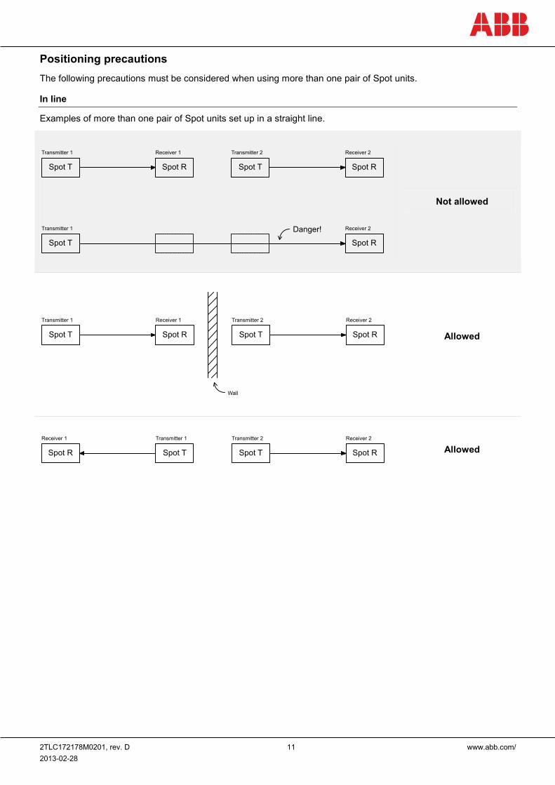
Positioning precautions The following precautions must be considered when using more than one pair of Spot units.
In line
Examples of more than one pair of Spot units set up in a straight line.
Not allowed
Allowed
Allowed
Spot T Spot R Spot T Spot R
Transmitter 1 Receiver 1 Transmitter 2 Receiver 2
Danger!
Spot T Spot R
Transmitter 1 Receiver 2
Spot T Spot R Spot T Spot R
Transmitter 1 Receiver 1 Transmitter 2 Receiver 2
Wall
Spot R Spot T Spot T Spot R
Receiver 1 Transmitter 1 Transmitter 2 Receiver 2

2TLC172178M0201, rev. E 12 www.abb.com/jokabsafety 2013-02-28
Parallel
Examples of more than one pair of Spot set up beside (or on top of) each other.
Not allowed*
Allowed
Allowed
* This setup may be non-safe depending on the distance between the Spot pairs. The minimum distance between the Spot pairs are calculated assuming the worst case scenario.
Worst case
Table 2
L x
5 m 0.44 m
10 m 0.87 m
20 m 1.75 m
35 m 3.06 m
Spot T
Danger!
Spot R
Transmitter 1 Receiver 1
Spot T Spot R
Transmitter 2 Receiver 2
Spot T Spot R
Transmitter 1 Receiver 1
Spot T Spot R
Transmitter 2 Receiver 2Wall
Spot R Spot T
Receiver 1 Transmitter 1
Spot T Spot R
Transmitter 2 Receiver 2
x
L
α = 2.5˚
Transmitter 1Spot T
Receiver 1Spot R
Transmitter 2Spot T
Receiver 2Spot R

2TLC172178M0201, rev. D 13 www.abb.com/ 2013-02-28
Calculation of minimum distance (worst case):
x = L × tan (2α)
where
x = minimum distance between two pairs
L = distance between transmitter and receiver
α = maximum spreading angle of light disturbance
NB: Example values are given in Table 2.
Reflecting surfaces
The Spot units must be set up in such a way that a reflecting surface may never be allowed to redirect the light from the transmitter into the receiver. The minimum distance to a reflective surface (horizontal or vertical) from which the Spot pair may be mounted is calculated depending on the distance between the transmitter and receiver.
Table 3
L x
≤ 3 m 131 mm
5 m 0.22 m
10 m 0.44 m
20 m 0.87 m
35 m 1.53 m
Calculation of minimum distance:
If the distance (L) between the transmitter and receiver is less than or equal to 3 meters (L ≤ 3 m) the minimum distance (x) is 131 mm.
If the distance (L) between transmitter and receiver is greater than 3 meters (L > 3 m) then the following formula applies:
x = L × tan (α)
where
x = minimum distance between Spot and reflective surface
L = distance between transmitter and receiver
α = maximum spreading angle of light disturbance
NB: Example values are given in Table 3.
x
L
α = 2.5˚
Spot T Spot R
Reflective surface

2TLC172178M0201, rev. E 14 www.abb.com/jokabsafety 2013-02-28
Installation precautions The safety light beam shall be installed by a trained electrician following the Safety regulations, standards and the Machinery directive.
All the safety functions shall be tested before the starting up of the system:
• Interrupt the dynamic safety circuit before this unit. The LED on the receiver should flash green.
• Interrupt the protection by obstructing the beam. The LED on the receiver should turn off.
• The LED on the receiver should light green if protection is OK and the safety circuit before this unit is not interrupted.
Caution! The main voltage for the system shall be switched off before installation, modifications or other adjustments are made that can risk the safety of the system.
Precautions when using safety light beam Spot with Vital 1:
• The information output switch on Vital 1 must be in position 2. A yellow indication lamp must be connected to the information output on Vital 1 and mounted where it is visible from the protected area. Refer to the Vital 1 manual for further details.
• Vital 1 must be installed within an electrical cabinet (or similar housing) with a minimum protection class rating of IP54.
• The information output signal from Spot must be connected to an indication lamp in such a way that it:
- Lights green when Spot is OK (uninterrupted)
- Lights red when Spot is interrupted
Caution! When changing the internal switch position, the power supply to Vital 1 must be disconnected before the connection blocks may be removed.
Maintenance
Warning!
The safety functions and the mechanics shall be tested regularly, at least once every year to confirm that all the safety functions are working properly (EN 62061:2005).
In case of breakdown or damage to the product, contact the nearest ABB/Jokab Safety Service Office or reseller. Do not try to repair the product yourself since it may accidentally cause permanent damage to the product, impairing the safety of the device which in turn could lead to serious injury to personnel.
Caution! This product shall be handled with caution: The product should be replaced with the same product type in a situation where it has been dropped on the floor, knocked strongly, exposed to extreme voltages, temperatures or humidity outside the specified limits.
In case of functional problems Test the sensors. The entire system shall be tested without disconnecting the power supply. Check that the LED indicators work as it is described in the section LED indication. Check that all safety units in the system are working properly by following the instructions in the respective manuals. If the problem cannot be resolved, please contact the nearest ABB/Jokab Safety Service Office or reseller.

2TLC172178M0201, rev. D 15 www.abb.com/ 2013-02-28
5 Operation LED indication LED Indication Description
LED on transmitter Green Power supply OK
LED on receiver
Green Alignment OK, safety circuit closed
Green (flash) Alignment OK, safety circuit opened before this unit
OFF Beam interrupted, safety circuit open

2TLC172178M0201, rev. E 16 www.abb.com/jokabsafety 2013-02-28
6 Model overview Available models Type Article number Description
Spot 35 T/R 2TLA020009R0500 Transmitter and receiver. Maximum distance 35 m.
Spot 10 T/R 2TLA020009R0600 Transmitter and receiver. Maximum distance 10 m.
Spot 10 T 2TLA020009R1500 Transmitter only. Part of Spot 10 T/R. Maximum distance 10 m.
Spot 35 T 2TLA020009R1600 Transmitter only. Part of Spot 35 T/R. Maximum distance 35 m.
Spot 10 R 2TLA020009R2500 Receiver only. Part of Spot 10 T/R. Maximum distance 10 m.
Spot 35 R 2TLA020009R2600 Receiver only. Part of Spot 35 T/R. Maximum distance 35 m.
Accessories Type Article number Description
JSM64 2TLA040007R0200 Pivot M18 bracket for Spot 10
JSRL2 2TLA020008R0100 Laser aligner for Spot 35
The Jokab Safety branded product with articlenumber beginning with 2TLJ is fully compatible with the ABB branded product with articlenumber beginning with 2TLA.
Spot 10 Maximum distance 10 m Article number: Spot 10 T/R: 2TLA020009R0600 Spot 10 T: 2TLA020009R1500 Spot 10 R: 2TLA020009R2500
Spot 35 Maximum distance 35 m Article number: Spot 35 T/R: 2TLA020009R0500 Spot 35 T: 2TLA020009R1600 Spot 35 R: 2TLA020009R2600
JSM64 Pivot M18 bracket for Spot 10 Article number: 2TLA040007R0200
JSRL2 Laser aligner for Spot 35 Article number: 2TLA020008R0100

2TLC172178M0201, rev. D 17 www.abb.com/ 2013-02-28
7 Technical data Manufacturer
Address ABB AB / JOKAB SAFETY Varlabergsvägen 11 SE-434 39 Kungsbacka Sweden
Power supply
Operating voltage 17-27 VDC, ripple ± 10 % (SELV/PELV)
Current consumption Transmitter: < 25 mA Receiver: < 15 mA
Output currents Information output: Max. 10 mA Dynamic signal output: Max. 30 mA
Time delay t (in/out) t < 250 µs
General
Protection class IP67
Response time Spot 10: 5 ms (+48 ms in Vital 1) Spot 35: 5 ms (+48 ms in Vital 1)
Light source Red visible light, 660 nm. Spreading angle < ± 2.5°
Minimum interruption time 90 ms
Min. detectable object 50 mm
Optical power Spot 10: < 0.1 mW Spot 35: < 0.2 mW
Range Spot 10: 0 – 10 m Spot 35: 0 – 35 m
Radiant power adjustment Spot 10: Trim pot. on transmitter
Responsivity adjustment Spot 35: Trim pot. on receiver
Mounting Spot 10: 2 x M18 nuts (provided) Spot 35: Either via mounting holes in the casing or with angle bracket JSM63 (provided)
Ambient temperature -25…+65°C
Size See drawing
Weight Spot 10: 2 x 21 g Spot 35: 2x 100 g
Material Spot 10: Steel housing with polyacryl lens protection Spot 35: Polyamide housing with polyacryl lens protection
Colour Spot 10: Steel grey Spot 35: Yellow and black
Connector M12 fixed connector

2TLC172178M0201, rev. E 18 www.abb.com/jokabsafety 2013-02-28
Safety performance / Standards
Conformity European Machinery Directive 2006/42/EC
EN ISO 12100:2012, EN 954-1:1996, EN ISO 13849-1:2008, EN 62061:2005, EN 61508:2010, EN 60204-1:2006+A1:2009, EN 61496-1:2004+A1:2008, EN 60664-1:2007, EN 61000-6-2:2005, EN 61000-6-4:2007 CLC/TS 61496-2:2006
EN ISO 13849-1 Performance level: PL e, Category 4 PFHd: 1.14*10-8
EN 954-1 Category 4
EN 61496 Type 4 (in combination with Vital 1)
Certifications TÜV Nord
Dimensions
Spot 10T
Spot 10 R
61.6
M18
M12
Trim potentiometer(radiant power adjustment)LED(indication)
61.6
M18
M12
LED(indication)

2TLC172178M0201, rev. D 19 www.abb.com/ 2013-02-28
Spot 35T
Spot 35R
15
68.5
48.3
30
14
67
3226.8
5
5.5(2x)
34.8 16
15
3.7(2x
)
LED(indication)
15
68.5
48.3
30
14
67
3226.8
5
5.5(2x)
34.8 16
15
3.7(2x
)
Trim potentiometer(responsivity adjustment)
LED(indication)

2TLC172178M0201, rev. E 20 www.abb.com/jokabsafety 2013-02-28
8 EC Declaration of conformity
ABB AB / JOKAB SAFETY Varlabergsvägen 11, SE-434 39 Kungsbacka, Sweden
www.abb.com/jokabsafety