spr-3301f-1 / spr-3801f-1 / spr-6501f-1 / spr-7501f-1 / spr
TRANSCRIPT
42,0426,0090,EA 022010
Operating InstructionsUSA
Inverter for grid-connectedphotovoltaic systems
SPR-3301f-1 / SPR-3801f-1 /SPR-6501f-1 / SPR-7501f-1 /SPR-10001f-1 / SPR-11401f-1 /SPR-11401f-3 / SPR-12001f-3
DMS # 001-67202 Rev.**

0
SunPower

1
SunPower
Dear reader,
Introduction Thank you for the trust you have placed in our company and congratulations
on buying this high-quality SunPower product. These instructions will help
you familiarize yourself with the product. Reading the instructions carefully
will enable you to learn about the many different features your SunPower
product has to offer. This will allow you to make full use of its advantages.
Please also note the safety rules to ensure greater safety when using the
product. Careful handling of the product will repay you with years of safe
and reliable operation. These are essential prerequisites for excellent re-
sults.

2
SunPower

3
SunPower
General These operating instructions contain important instructions for the SunPow-
er SPR-f that must be followed during installation and maintenance of the
inverter.
The SunPower SPR-f is designed and tested according to international
safety requirements, but as with all electrical and electronic equipment, cer-
tain precautions must be observed when installing and/or operating the
SunPower SPR-f. !
To reduce the risk of personal injury and to ensure the safe installation and
operation of the SunPower SPR-f, you must carefully read and follow all in-
structions and safety instructions in these operating instructions.
Electrical in-
stallations
All electrical installations must be carried out in accordance with the Nation-
al Electrical Code, ANSI/NFPA 70, and any other codes and regulations ap-
plicable to the installation site.
For installations in Canada, the installations must be done in accordance
with applicable Canadian standards.
IMPORTANT SAFETY
INSTRUCTIONS
SAVE THESE INSTRUCTIONS

4
SunPower

5
SunPower
Contents
Safety rules ..................................................................................................................... 9
General Information 15
Protection of Persons and Equipment ............................................................................ 17
Safety ......................................................................................................................... 17
Protection of Persons and Equipment ........................................................................ 17
Galvanic isolation........................................................................................................ 17
Monitoring the Grid ..................................................................................................... 17
Information on "field adjustable trip points"................................................................. 18
FCC compliance ......................................................................................................... 18
Ground fault detector / interrupter............................................................................... 18
Standards and regulations.......................................................................................... 18
Declaration of conformity ............................................................................................ 18
The SunPower SPR-f in the photovoltaic system ........................................................... 19
General ....................................................................................................................... 19
Tasks .......................................................................................................................... 19
Converting DC to AC Current ..................................................................................... 19
Fully Automatic Operational Management.................................................................. 20
Display function and data communication .................................................................. 20
System upgrade.......................................................................................................... 20
Forced Ventilation....................................................................................................... 20
Power derating............................................................................................................ 21
Installation and Startup 23
SunPower SPR-f installation and connection ................................................................. 25
Safety ......................................................................................................................... 25
SunPower SPR-f construction .................................................................................... 25
Connection diagram.................................................................................................... 26
Overview..................................................................................................................... 26
Choosing the Location .................................................................................................... 27
Choosing the location in general ................................................................................ 27
Choosing a Location for Inside Installation................................................................. 28
Choosing a location for outdoor installation................................................................ 28
SunPower SPR-f connection options.............................................................................. 29
Connection Options .................................................................................................... 29
Knockouts on the SunPower SPR-f ................................................................................ 31
General ....................................................................................................................... 31
Knockouts for wire inputs............................................................................................ 31
SunPower SPR-f installation........................................................................................... 33
General ....................................................................................................................... 33
Assembling the wall bracket ....................................................................................... 33
Recommended screws for wall bracket assembly...................................................... 33
Attaching the wall bracket - mounting height .............................................................. 33
Attaching the wall bracket to a concrete or brick wall ................................................. 34

6
SunPower
Attaching the wall bracket to a wooden wall ............................................................... 34
Attaching the wall bracket to a metal carrier............................................................... 35
Lifting the Inverter ....................................................................................................... 35
Installing the inverter................................................................................................... 36
Installation of several inverters ................................................................................... 37
Connecting the SunPower SPR-f to the public grid (AC)................................................ 38
Overview of available grids......................................................................................... 38
Monitoring the Grid ..................................................................................................... 40
Systems with more than one inverter ......................................................................... 41
AC-side terminals and grounding terminals................................................................ 41
Cross section of AC wires........................................................................................... 42
Safety ......................................................................................................................... 43
Connecting the SunPower SPR-f to the public grid (AC)............................................ 44
Connecting grounding electrode wire ......................................................................... 45
Recommendation for the AC-side overcurrent protection........................................... 45
Additional external AC and/or DC disconnect............................................................. 46
Connecting solar module strings to the SunPower SPR-f (DC)...................................... 47
General information about solar modules................................................................... 47
Safety ......................................................................................................................... 47
DC terminals ............................................................................................................... 48
Polarity reversal of solar module strings..................................................................... 48
Overview..................................................................................................................... 48
Solar Module Ground at Positive Pole: Connecting Solar Module Strings ..................... 49
Solar Module Ground at Positive Pole........................................................................ 49
Wire cross section of solar module strings ................................................................. 50
Solar Module Ground at Positive Pole: Connecting Solar Module Strings ................. 50
Criteria for the Proper Selection of String Fuses ............................................................ 54
DC disconnect requirements ...................................................................................... 54
General ....................................................................................................................... 54
Criteria for the proper selection of string fuses ........................................................... 54
Effects of Using Underrated Fuses............................................................................. 54
Fuse recommendations .............................................................................................. 55
Application example.................................................................................................... 55
Solar Module Ground at Negative Pole: Connecting Solar Module Strings.................... 56
Solar Module Ground at Negative Pole ...................................................................... 56
Wire cross section of solar module strings ................................................................. 57
Solar module ground at negative pole: Connecting solar module strings................... 57
Criteria for the Proper Selection of String Fuses ............................................................ 62
DC disconnect requirements ...................................................................................... 62
General ....................................................................................................................... 62
Criteria for the proper selection of string fuses ........................................................... 62
Effects of Using Underrated Fuses............................................................................. 62
Fuse recommendations .............................................................................................. 63
Application example.................................................................................................... 63
Closing the inverter ......................................................................................................... 64
Closing the inverter..................................................................................................... 64
Opening the SunPower SPR-f for service/maintenance............................................. 64
Commissioning ............................................................................................................... 65
Factory pre-set configuration...................................................................................... 65

7
SunPower
Requirements for start-up operation........................................................................... 65
Commissioning ........................................................................................................... 65
Selecting the grid ........................................................................................................ 66
Setting the inverter for solar module ground at negative pole .................................... 69
Startup phase during startup operation ...................................................................... 71
Operation 73
Product description SunPower SPR-f ............................................................................. 75
Controls and Indicators............................................................................................... 75
Display ........................................................................................................................ 76
Operating Status LED................................................................................................. 77
Startup Phase and Grid Feed-in Mode ........................................................................... 79
Startup phase ............................................................................................................. 79
Test procedure............................................................................................................ 79
Operation of Feeding Energy into the Grid ................................................................. 80
Navigation in the Menu Level.......................................................................................... 81
Activating display illumination ..................................................................................... 81
Accessing the Menu Level.......................................................................................... 81
The Display Modes ......................................................................................................... 82
Display modes ............................................................................................................ 82
Selecting a display mode............................................................................................ 82
Overview of display values ......................................................................................... 83
Display Values in "Now" Display Mode........................................................................... 84
Selecting the "Now" Display Mode ............................................................................. 84
Display values in the ‘Now’ display mode................................................................... 84
"N.A." - display value not available ............................................................................. 86
Display values in the Day / Total display modes............................................................. 87
General ....................................................................................................................... 87
Selecting "Day / Total" display modes ........................................................................ 87
Display values in the ‘Day / Total’ display modes....................................................... 88
"N.A." - display value not available ............................................................................. 89
The Setup Menu ............................................................................................................. 90
Presetting.................................................................................................................... 90
Accessing the Setup Menu......................................................................................... 90
Scrolling through Menu Items..................................................................................... 91
Menu Items in the Setup Menu ....................................................................................... 92
STANDBY................................................................................................................... 92
CONTRAST................................................................................................................ 93
LIGHT MODE ............................................................................................................. 93
CASH.......................................................................................................................... 93
CO2 ............................................................................................................................ 94
YIELD ......................................................................................................................... 94
IG no. .......................................................................................................................... 95
DAT COM ................................................................................................................... 95
STATE PS .................................................................................................................. 95
VERSION.................................................................................................................... 96
Setting and Displaying Menu Items ................................................................................ 97
Setting Menu Items - General..................................................................................... 97
8
SunPower
Application example: setting the currency and rate .................................................... 98
Troubleshooting and Maintenance 101
Status Diagnosis and Troubleshooting ........................................................................... 103
Displaying Status Codes............................................................................................. 103
Normal Operation Status Codes................................................................................. 103
Total failure ................................................................................................................. 103
Status codes on SunPower SPR-f with several power stage sets.............................. 104
Class 1 Status Codes ................................................................................................. 105
Class 2 Status Codes ................................................................................................. 107
Class 3 status codes................................................................................................... 108
Class 4 status codes................................................................................................... 110
Class 5 status codes................................................................................................... 119
Customer Service ....................................................................................................... 123
Maintenance ................................................................................................................... 124
Safety ......................................................................................................................... 124
General ....................................................................................................................... 124
Operation in Dusty Environments ............................................................................... 125
Opening the SunPower SPR-f for service/maintenance............................................. 125
Replacing String Fuses................................................................................................... 126
Safety ......................................................................................................................... 126
Preparation ................................................................................................................. 126
Replacing string fuses ................................................................................................ 127
Finally... ...................................................................................................................... 128
Replacing GFDI fuse....................................................................................................... 130
Safety ......................................................................................................................... 130
Preparation ................................................................................................................. 130
Replacing GFDI fuse .................................................................................................. 131
Finally... ...................................................................................................................... 132
Appendix 133
Technical Data ................................................................................................................ 135
SunPower SPR-3301f-1 UNI ...................................................................................... 135
SunPower SPR-3801f-1 UNI ...................................................................................... 137
SunPower SPR-6501f-1 UNI ...................................................................................... 139
SunPower SPR-7501f-1 UNI ...................................................................................... 141
SunPower SPR-10001f-1 UNI .................................................................................... 143
SunPower SPR-11401f-1 UNI .................................................................................... 145
SunPower SPR-11401f-3-208/240 Delta.................................................................... 147
SunPower SPR-12001f-3-277 WYE........................................................................... 149
Field adjustable trip points .......................................................................................... 151
Relevant Standards and Directives................................................................................. 152
Relevant standards and directives.............................................................................. 152
Grid Failure ................................................................................................................. 152
9
SunPower
Safety rules
Safety Rules
Explanation
If you see any of the symbols depicted in the "Safety rules," special care is
required.
General
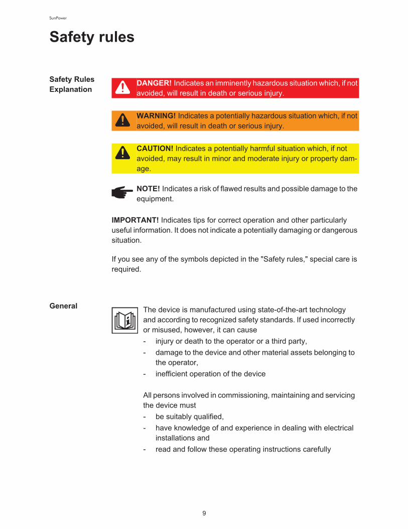
DANGER! Indicates an imminently hazardous situation which, if not
avoided, will result in death or serious injury.
WARNING! Indicates a potentially hazardous situation which, if not
avoided, will result in death or serious injury.
CAUTION! Indicates a potentially harmful situation which, if not
avoided, may result in minor and moderate injury or property dam-
age.
NOTE! Indicates a risk of flawed results and possible damage to the
equipment.
IMPORTANT! Indicates tips for correct operation and other particularly
useful information. It does not indicate a potentially damaging or dangerous
situation.
The device is manufactured using state-of-the-art technology
and according to recognized safety standards. If used incorrectly
or misused, however, it can cause
- injury or death to the operator or a third party,
- damage to the device and other material assets belonging to
the operator,
- inefficient operation of the device!
All persons involved in commissioning, maintaining and servicing
the device must
- be suitably qualified,
- have knowledge of and experience in dealing with electrical
installations and
- read and follow these operating instructions carefully!

10
SunPower
Utilization in
Accordance
with "Intended
Purpose"
The operating instructions must always be at hand wherever the
device is being used. In addition to the operating instructions, at-
tention must also be paid to any generally applicable and local
regulations regarding accident prevention and environmental
protection.!
All safety and danger notices on the device
- must be kept in a legible state
- must not be damaged/marked
- must not be removed
- must not be covered, pasted or painted over!
For the location of the safety and danger notices on the device,
refer to the section headed "General" in the operating instructions
for the device.!
Before switching on the device, remove any faults that could
compromise safety.!
Your personal safety is at stake!
The device is to be used exclusively for its intended purpose.
Utilization for any other purpose, or in any other manner, shall be
deemed to be "not in accordance with the intended purpose." The
manufacturer shall not be liable for any damage resulting from
such improper use.!
Utilization in accordance with the "intended purpose" also in-
cludes
- carefully reading and obeying all the instructions and all the
safety and danger notices in the operating instructions
- performing all stipulated inspection and servicing work
- installation as specified in the operating instructions!
The following guidelines should also be applied where relevant:
- Regulations of the power supply company regarding energy
fed into the grid
- Instructions from the solar module manufacturer

11
SunPower
Environmen-
tal Conditions
Qualified Ser-
vice Engineers
Safety Mea-
sures at the In-
stallation
Location
When installing devices with openings for cooling air, ensure that the cool-
ing air can enter and exit unhindered through the vents. Only operate the
device in accordance with the degree of protection shown on the rating
plate.
Operation or storage of the device outside the stipulated area will
be deemed as "not in accordance with the intended purpose."
The manufacturer is not responsible for any damages resulting
from unintended use.
For exact information on permitted environmental conditions,
please refer to the "Technical data" in the operating instructions.
The servicing information contained in these operating instruc-
tions is intended only for the use of qualified service engineers.
An electric shock can be fatal. Do not perform any actions other
than those described in the documentation. This also applies to
those who may be qualified.!
All cables and leads must be secured, undamaged, insulated and
adequately dimensioned. Loose connections, scorched, dam-
aged or inadequately dimensioned cables and leads must be im-
mediately repaired by authorized personnel.!
Maintenance and repair work must only be carried out by autho-
rized personnel.
It is impossible to guarantee that externally procured parts are
designed and manufactured to meet the demands made on
them, or that they satisfy safety requirements. Use only original
replacement parts (also applies to standard parts).!
Do not carry out any modifications, alterations, etc. without the
manufacturer's consent.!
Components that are not in perfect condition must be changed
immediately.

12
SunPower
Data Regard-
ing Noise
Emission Val-
ues
EMC device
classifications
EMC Measures
The inverter generates a maximum sound power level of < 80
dB(A) (ref. 1 pW) when operating under full load in accordance
with IEC 62109-1.
The device is cooled as quietly as possible with the aid of an elec-
tronic temperature control system, and depends on the amount
of converted power, the ambient temperature, the level of soiling
of the device, etc.!
It is not possible to provide a workplace-related emission value
for this device, because the actual sound pressure level is heavily
influenced by the installation situation, the power quality, the sur-
rounding walls and the properties of the room in general.
Devices with emission class A:
- are only designed for use in an industrial setting
- can cause line-bound and radiated interference in other ar-
eas
Devices with emission class B:
- satisfy the emissions criteria for residential and industrial ar-
eas. This is also true for residential areas in which the energy
is supplied from the public low voltage grid.
EMC device classification as per the rating plate or technical da-
ta.
In certain cases, even though a device complies with the stan-
dard limit values for emissions, it may affect the application area
for which it was designed (e.g., when there is sensitive equip-
ment at the same location, or if the site where the device is in-
stalled is close to either radio or television receivers). If this is the
case, then the operator is obliged to take appropriate action to
rectify the situation.

13
SunPower
Grid Connec-
tion
Electrical In-
stallations
Protective
Measures
against ESD
Safety Mea-
sures in Nor-
mal Operation
High-performance devices (> 16 A) can affect the voltage quality
of the grid because of a high output current in the main supply.
This may affect a number of types of device in terms of:
- connection restrictions
- criteria with regard to maximum permissible mains imped-
ance *)
- criteria with regard to minimum short-circuit power require-
ment *)
*) at the interface with the public grid
see Technical Data!
In this case, the operator or the person using the device should
check whether or not the device is allowed to be connected,
where appropriate through discussion with the power supply
company.
Electrical installations must only be carried out according to rele-
vant national and local standards and regulations.
Danger of damage to electrical components from electrical dis-
charge. Suitable measures should be taken to protect against
ESD when replacing and installing components.
Only operate the device when all protection devices are fully
functional. If the protection devices are not fully functional, there
is a risk of
- injury or death to the operator or a third party,
- damage to the device and other material assets belonging to
the operator,
- inefficient operation of the device!

14
SunPower
Safety Sym-
bols
Disposal
Backup
Copyright
Any safety devices that are not functioning properly must be re-
paired by authorized personnel before the device is switched on.!
Never bypass or disable protection devices.
Devices with the CE marking satisfy the essential requirements
of the low-voltage and electromagnetic compatibility directives.
(Further details can be found in the appendix or the chapter enti-
tled "Technical data" in your documentation.)
Do not dispose of this device with normal domestic waste! To
comply with the European Directive 2002/96/EC on Waste Elec-
trical and Electronic Equipment and its implementation as nation-
al law, electrical equipment that has reached the end of its life
must be collected separately and returned to an approved recy-
cling facility. Any device that you no longer require must be re-
turned to your dealer, or you must locate the approved collection
and recycling facilities in your area. Ignoring this European Direc-
tive may have potentially adverse affects on the environment and
your health!
The user is responsible for backing up any changes made to the
factory settings. The manufacturer accepts no liability for any de-
leted personal settings.
Copyright of these operating instructions remains with the manu-
facturer.
Text and illustrations are technically correct at the time of going
to print. The right to make modifications is reserved. The contents
of the operating instructions shall not provide the basis for any
claims whatsoever on the part of the purchaser. If you have any
suggestions for improvement, or can point out any mistakes that
you have found in the operating instructions, we will be most
grateful for your comments.

SunPower
General Information

16
SunPower

17
SunPower
Protection of Persons and Equipment
Safety
Protection of
Persons and
Equipment
The design and function of the inverter offer a maximum level of safety, both
during installation as well as operation.
The inverter provides operator and equipment protection through:
a) galvanic isolation
b) monitoring the grid
Galvanic isola-
tion
The inverter is equipped with a high frequency transformer that ensures gal-
vanic isolation between the DC side and the grid, thus ensuring the highest
possible safety.
Monitoring the
Grid
Whenever conditions in the electric grid are inconsistent with standard con-
ditions (for example, grid switch-off, interruption), the inverter will immedi-
ately stop operating and interrupt the supply of power into the grid.
Grid monitoring is carried out using:
WARNING! An electric shock can be fatal. Danger from grid voltage
and DC voltage from solar modules.
- The connection area should only be opened by a licensed elec-
trician.
- The separate power stage set area should only be disconnected
from the connection area after first being disconnected from the
grid power.
- The separate power stage set area should only be opened by
trained service personnel.
Never work with live wires! Prior to all connection work, make sure
that the AC and DC wires are not charged.
WARNING! If the equipment is used or tasks are carried out incor-
rectly, serious injury or damage may result. Only qualified personnel
are authorized to install your inverter and only within the scope of
the respective technical regulations. It is essential that you read the
"Safety regulations" chapter before commissioning the equipment
or carrying out maintenance work.

18
SunPower
- Voltage monitoring
- Frequency monitoring
- Monitoring islanding conditions
Information on
"field adjust-
able trip
points"
The inverter is equipped with field adjustable trip points. For further informa-
tion, please contact SunPower Corp. technical support at the following e-
mail address: [email protected].
FCC compli-
ance
Ground fault
detector / in-
terrupter
The inverter is equipped with a ground fault detection and interruption (GF-
DI) circuit as required by UL 1741 and the National Electrical code.!
Depending on the system configuration either the PV array’s negative or
positive conductor is connected to the grounding system in the inverter. If a
ground fault occurs in the DC wiring, the inverter disconnects from the grid.
Standards and
regulations
Your inverter complies with the requirements for the following standards "In-
verters, converters and controllers for use in independent power systems":
- UL1741-2005
- IEEE 1547-2003
- IEEE 1547.1
- ANSI / IEEE C62.41
- C22.2 No. 107.1-01 (Sep. 2001)
The ground-fault detection and interruption is in compliance with NEC 690
building code requirements.
Declaration of
conformity
Relevant declarations of conformity can be found in the appendix to these
operating instructions.
This device complies with Part 15 of the FCC Rules. Operation
is subject to the following conditions:!
(1) This device may not cause harmful interference, and!
(2) This device must accept any interference received, includ-
ing interference that may cause undesired operation.
19
SunPower
The SunPower SPR-f in the photovoltaic
system
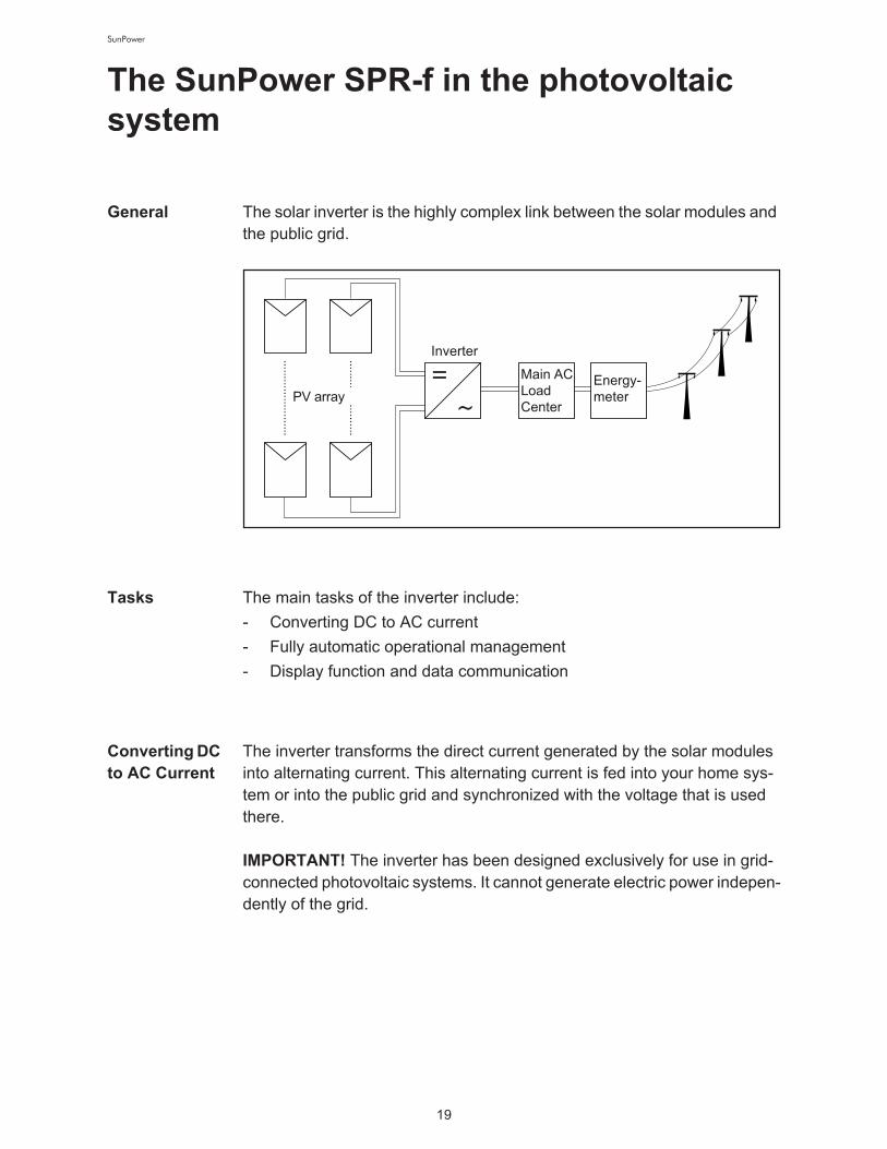
General The solar inverter is the highly complex link between the solar modules and
the public grid.
Tasks The main tasks of the inverter include:
- Converting DC to AC current
- Fully automatic operational management
- Display function and data communication
Converting DC
to AC Current
The inverter transforms the direct current generated by the solar modules
into alternating current. This alternating current is fed into your home sys-
tem or into the public grid and synchronized with the voltage that is used
there.
Inverter
Main AC
Load
Center
Energy-
meterPV array
IMPORTANT! The inverter has been designed exclusively for use in grid-
connected photovoltaic systems. It cannot generate electric power indepen-
dently of the grid.

20
SunPower
Fully Automat-
ic Operational
Management
The inverter is fully automatic. Starting at sunrise, as soon as the solar mod-
ules generate enough power, the automatic control unit starts monitoring
voltage and frequency. As soon as there is a sufficient level of irradiance,
your solar inverter starts feeding energy to the grid.
The inverter control system ensures that the maximum possible power out-
put is drawn from the solar modules at all times. !
This function is called MPPT (Maximum Power Point Tracking).
As dusk starts and there is no longer sufficient energy available to feed
power into the grid, the inverter unit shuts down the grid connection com-
pletely and stops operating. All settings and recorded data are saved.
Display func-
tion and data
communica-
tion
The display on the inverter is the interface between the inverter and the op-
erator. The design of the display is geared towards simple operation and
making system data available as long as the inverter operates.
The inverter is equipped with a basic logging function to monitor minimum
and maximum data on a daily and a cumulative basis. These values are
shown on the display.
A wide range of data communication products allows for many possibilities
of recording and viewing data.
System up-
grade
The inverter is designed for various system upgrades, e.g.:
- Upgrades that enable the inverter to communicate with external system
upgrades as well as other inverters
- Datalogger (when using a PC to record and manage data from your
photovoltaic system), includes Datalogger and a modem interface
Forced Venti-
lation
The inverter's temperature-controlled, variable-speed fan with ball-bearing
support provides:
- optimal inverter cooling
- efficiency increases
- cooler components, thus improving service life
- least possible energy consumption and lowest possible noise level
- weight reduction due to a reduction of the cooling element surface

21
SunPower
Power derat-
ing
Should there be insufficient heat dissipation in spite of the fan operating at
maximum speed (for example, inadequate heat transfer away from the heat
sinks), the power will be derated to protect the inverter when the ambient
temperature reaches approx. 40 °C and above.
Derating the power reduces the output of the inverter for a short period suf-
ficient to ensure that the temperature will not exceed the permissible limit.!
Your inverter will remain ready for operation as long as possible without any
interruption.

22
SunPower

SunPower
Installation and Startup

24
SunPower
25
SunPower
SunPower SPR-f installation and connec-
tion
Safety
SunPower
SPR-f con-
struction
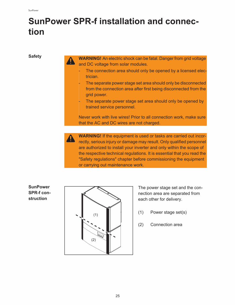
The power stage set and the con-
nection area are separated from
each other for delivery. !
(1) Power stage set(s) !
(2) Connection area
WARNING! An electric shock can be fatal. Danger from grid voltage
and DC voltage from solar modules.
- The connection area should only be opened by a licensed elec-
trician.
- The separate power stage set area should only be disconnected
from the connection area after first being disconnected from the
grid power.
- The separate power stage set area should only be opened by
trained service personnel.
Never work with live wires! Prior to all connection work, make sure
that the AC and DC wires are not charged.
WARNING! If the equipment is used or tasks are carried out incor-
rectly, serious injury or damage may result. Only qualified personnel
are authorized to install your inverter and only within the scope of
the respective technical regulations. It is essential that you read the
"Safety regulations" chapter before commissioning the equipment
or carrying out maintenance work.
(1)
(2)

26
SunPower
Connection di-
agram
* may be required by local authorities!
** may be required depending on grid configuration!
*** depending on inverter type
Overview ‘SunPower SPR-f installation and connection’ contains the following sec-
tions:
- Choosing the location
- SunPower SPR-f connection options
- Knockouts on the SunPower SPR-f
- SunPower SPR-f installation
- Connecting the SunPower SPR-f to the public grid (AC)
- Connecting solar module strings to the SunPower SPR-f (DC)
- Attaching power stage sets and closing the SunPower SPR-f
SunPower SPR-f Inverter
Energy-
meter
AC distribution
panel
DC disconnect
DC terminal block
String fuses
DC -
DC +
PV frame ground
L1
L2
N
Grounding terminal
Grounding electrode terminal *
L1N**
L2
L3
L3***
Main grounding system
Lockable AC
disconnect
switch
27
SunPower
Choosing the Location
Choosing the
location in
general
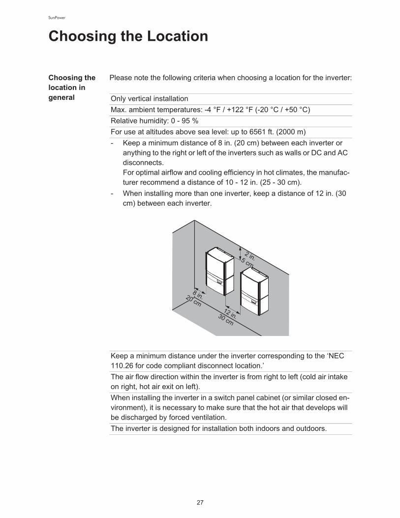
Please note the following criteria when choosing a location for the inverter:
Only vertical installation
Max. ambient temperatures: -4 °F / +122 °F (-20 °C / +50 °C)
Relative humidity: 0 - 95 %
For use at altitudes above sea level: up to 6561 ft. (2000 m)
- Keep a minimum distance of 8 in. (20 cm) between each inverter or
anything to the right or left of the inverters such as walls or DC and AC
disconnects.!
For optimal airflow and cooling efficiency in hot climates, the manufac-
turer recommend a distance of 10 - 12 in. (25 - 30 cm).
- When installing more than one inverter, keep a distance of 12 in. (30
cm) between each inverter.
Keep a minimum distance under the inverter corresponding to the ‘NEC
110.26 for code compliant disconnect location.’
The air flow direction within the inverter is from right to left (cold air intake
on right, hot air exit on left).
When installing the inverter in a switch panel cabinet (or similar closed en-
vironment), it is necessary to make sure that the hot air that develops will
be discharged by forced ventilation.
The inverter is designed for installation both indoors and outdoors.
2 in.5 cm
12 in.30 cm
8 in.20 cm
28
SunPower
Choosing a
Location for
Inside Installa-
tion
Choosing a lo-
cation for out-
door
installation
During certain operation phases the inverter may produce a slight noise.
For this reason it should not be installed in an occupied living area.
Do not install the inverter in:
- areas with large amounts of dust
- areas with large amounts of conducting dust particles (e.g., iron filings)
- areas with corrosive gases, acids or salts
- areas where there is an increased risk of accidents, e.g., from farm an-
imals (horses, cattle, sheep, pigs, etc.)
- stables or adjoining areas
- storage areas for hay, straw, chaff, animal feed, fertilizers, etc.
- storage or processing areas for fruit, vegetables or winegrowing prod-
ucts
- areas used in the preparation of grain, green fodder or animal feeds
- greenhouses
NEMA 3R protection means that the inverter is not susceptible to water
spray from any direction.!
However, the manufacturer recommends, if possible, that the inverter not
be exposed to direct moisture or to a direct water jet (e.g., from sprinklers).
In order to protect the display, the inverter should not be exposed to direct
sunlight. Ideally, the inverter should be installed in a protected location,
e.g., near the solar modules or under a roof overhang.
Do not install the inverter:
- where it can be exposed to ammonia, corrosive gasses, acids or salts
(e.g., fertilizer storage areas, vent openings of livestock stables, chem-
ical plants, tanneries)

29
SunPower
SunPower SPR-f connection options
Connection
Options
Item Description
(1) Jumper slot SMON
(2) DC- main switch wire
(3) 6 x fuse holder with fuse cover, for stringfuses
(4) Jumper slot SMOFF
(5) Plug-in card (IG Brain)
(6) Open card slot for an option card
(7) Open card slot for an option card
(8) Plug-in card NL-MON!
Only at SunPower SPR-12001f-3-277WYE: Open card slot for an
option card
(9) DC+ main switch wire
(10) 6 DC+ terminals
(11) Fuse holder with fuse cover, for GFDI-fuse

30
SunPower
(12) AC-side terminals
(13) 3 x grounding terminals
(14) Strain relief for solar module strings
(15) 6 DC- terminals
(16) DC main switch
Item Description

31
SunPower
Knockouts on the SunPower SPR-f
General The inverter contains several knockouts of different sizes. When knocked
out, the openings are used for the inputs of various wires.
Knockouts for
wire inputsKnockouts on the left-hand side Knockouts on the right-hand side
Knockouts on the underside and on the backside
Item Description
(1) Knockout, diameter 3/4 in. / 1 in.!
e.g., for DC wire, surge arrester
(2) Knockout, diameter 1/2 in. / 3/4 in.!
only for data wires
(3) Knockout, diameter 3/4 in. / 1 in.!
e.g., for AC wire, surge arrester
(2)
(1)
(3)
(1)
(3)(2)
(1)
(2)
(3) (4)(5)
(1)(5)
(3)
(4)(6) (7)

32
SunPower
(4) Knockout, diameter 1/2 in. / 3/4 in.!
e.g., for AC wire, surge arrester
(5) Knockout, diameter 1/2 in. / 3/4 in.!
e.g., for DC wire, surge arrester
(6) FTX 25 fixing screw
(7) FTX 25 fixing screw
NOTE! When using back wire inputs:
- seal enclosure as per NEMA 3R before outside operationn
Item Description
NOTE!
- The larger knockouts should only be removed from the outside
in.
- The smaller knockouts should be removed from the inside out.
- Only remove the number of knockouts required for the available
wire inputs.
CAUTION! Danger of damaging the plastic base when removing
the knockouts on the bottom.
- Before removing, remove the 3 fixing screws (6) and (7)
- Remove the metal insert from the plastic base
- Remove the required knockouts
- Replace the metal insert into the plastic base
- Secure the metal insert using the 3 fixing screws (6) and (7)
33
SunPower
SunPower SPR-f installation
General
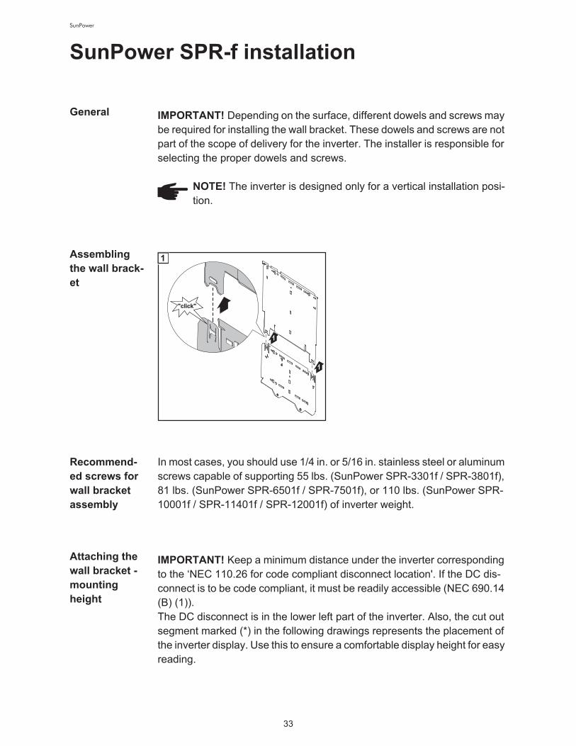
Assembling
the wall brack-
et
Recommend-
ed screws for
wall bracket
assembly
In most cases, you should use 1/4 in. or 5/16 in. stainless steel or aluminum
screws capable of supporting 55 lbs. (SunPower SPR-3301f / SPR-3801f),
81 lbs. (SunPower SPR-6501f / SPR-7501f), or 110 lbs. (SunPower SPR-
10001f / SPR-11401f / SPR-12001f) of inverter weight.
Attaching the
wall bracket -
mounting
height
IMPORTANT! Depending on the surface, different dowels and screws may
be required for installing the wall bracket. These dowels and screws are not
part of the scope of delivery for the inverter. The installer is responsible for
selecting the proper dowels and screws.
NOTE! The inverter is designed only for a vertical installation posi-
tion.
"click"
1
1
1
IMPORTANT! Keep a minimum distance under the inverter corresponding
to the ‘NEC 110.26 for code compliant disconnect location'. If the DC dis-
connect is to be code compliant, it must be readily accessible (NEC 690.14
(B) (1)).!
The DC disconnect is in the lower left part of the inverter. Also, the cut out
segment marked (*) in the following drawings represents the placement of
the inverter display. Use this to ensure a comfortable display height for easy
reading.

34
SunPower
Attaching the
wall bracket to
a concrete or
brick wall
Attaching the
wall bracket to
a wooden wall
IMPORTANT! The cut out segment marked (*) represents the placement of
the inverter display. Use this to ensure a comfortable display height for easy
reading.
min. 50 mm
min. 2 in.
2
1
1
7
3
5
4
6
(*)
1
22
3
4
1
6
5
2
2
6 x
4
6
7
1
5
23
3
IMPORTANT! The cut out segment marked (*) represents the placement of
the inverter display. Use this to ensure a comfortable display height for easy
reading.
9
1
1
2
3
4
(*)
1
9
1
2
5
2

35
SunPower
Attaching the
wall bracket to
a metal carrier
Lifting the In-
verter
SunPower Corporation recommends using a commercially-available vacu-
um lifting pad for flat surfaces to lift the connection area and power stage
set.
IMPORTANT!
- The vacuum lifting pads must be designed for the weight of the connec-
tion area and power stage set.
- Follow all safety instructions from the vacuum lifting pad manufacturer.
- Vacuum lifting pads are not part of the scope of delivery for the inverter.
Weight information for the connection area and power stage set:
IMPORTANT! The cut out segment marked (*) represents the placement of
the inverter display. Use this to ensure a comfortable display height for easy
reading.
NOTE! When installing us-
ing a metal carrier, the in-
verter should not be exposed to
rainwater or water spray at the
back. Ensure proper rainwater or
spray water protection.
1
4 x
3
4
22
(*)
1
Inverter Connection area Power stage set
SunPower SPR-3301f-1 24 lbs. 31 lbs.
SunPower SPR-3801f-1 24 lbs. 31 lbs.
SunPower SPR-6501f-1 24 lbs. 57 lbs.
SunPower SPR-7501f-1 24 lbs. 57 lbs.
SunPower SPR-10001f-1 26 lbs. 84 lbs.
SunPower SPR-11401f-1 26 lbs. 84 lbs.
SunPower SPR-11401f-3 26 lbs. 84 lbs.
SunPower SPR-12001F-3 26 lbs. 84 lbs.

36
SunPower
Installing the
inverterNOTE! For inverter assembly, please ensure that:
- the wall bracket is fixed securely to the wall
- the connector is hung and fixed to the wall bracket
- the power stage set is hung on the wall bracket and fixed to the
connector
2
1
A
B
1
1
2
2
1
4
2
3
3
1
3
2
4
4
3
3
12
5
3
2
1
23
AB
6

37
SunPower
For mounting the power stage set to
the connection area use the screws
from the plastic bag affixed to the
wall bracket.
Installation of
several invert-
ers
Several inverters can be easily installed and connected next to each other
using the side knockouts on the inverter, e.g.:
1
12 3
1
7
NOTE! All electrical installations must be carried out in accordance
with the National Electrical Code, ANSI/NFPA 70, and any other
codes and regulations applicable to the installation site.
For installations in Canada, the installations must be done in accor-
dance with applicable Canadian standards.
CDCDCD
DATCOM = data communication
DATCOM DATCOM
AC AC
38
SunPower
Connecting the SunPower SPR-f to the pub-
lic grid (AC)
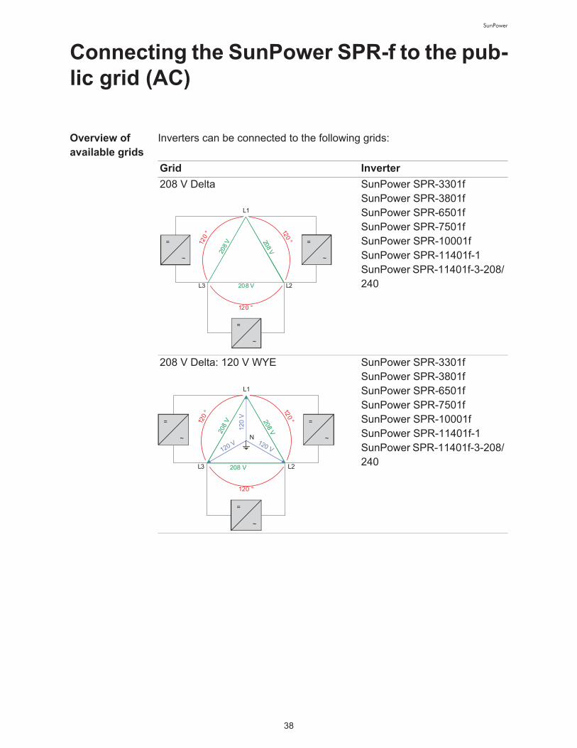
Overview of
available grids
Inverters can be connected to the following grids:
Grid Inverter
208 V Delta SunPower SPR-3301f !
SunPower SPR-3801f !
SunPower SPR-6501f !
SunPower SPR-7501f !
SunPower SPR-10001f !
SunPower SPR-11401f-1!
SunPower SPR-11401f-3-208/
240
208 V Delta: 120 V WYE SunPower SPR-3301f !
SunPower SPR-3801f !
SunPower SPR-6501f !
SunPower SPR-7501f !
SunPower SPR-10001f !
SunPower SPR-11401f-1 !
SunPower SPR-11401f-3-208/
240
120
° 120 °
120 °
208
V 208 V
208 V
L1
L2L3
=
~
=
~
=
~
12
0 V
120 V 120 V
120
° 120 °
120 °
208 V
208 V
208 V
L1
L2
N
L3
=
~
=
~
=
~

39
SunPower
240 V Delta SunPower SPR-3301f !
SunPower SPR-3801f !
SunPower SPR-6501f !
SunPower SPR-7501f !
SunPower SPR-10001f !
SunPower SPR-11401f-1 !
SunPower SPR-11401f-3-208/
240
240 V: 120 V Stinger SunPower SPR-3301f !
SunPower SPR-3801f !
SunPower SPR-6501f !
SunPower SPR-7501f !
SunPower SPR-10001f!
SunPower SPR-11401f-1
240 V: 120 V Split phase SunPower SPR-3301f !
SunPower SPR-3801f !
SunPower SPR-6501f !
SunPower SPR-7501f !
SunPower SPR-10001f!
SunPower SPR-11401f-1
Grid Inverter
240 V24
0 V
240 V
120
° 120 °
120 °
L1
L2L3
=
~
=
~
=
~
240 V24
0 V12
0 ° 12
0 °
120 °
120 V120 V
L3
L1
N
L2
=
~
=
~
=
~
180 °
120 V 120 V
240 V
2L1LN
=
~

40
SunPower
Monitoring the
Grid
480 V Delta: 277 V WYE SunPower SPR-3301f !
SunPower SPR-3801f !
SunPower SPR-6501f !
SunPower SPR-7501f !
SunPower SPR-10001f!
SunPower SPR-11401f-1!
!
SunPower SPR-12001f-3-
277WYE
480 V Delta NOTE! Do not connect
SunPower SPR-f in-
verters to the 480 V Delta grid.
Grid Inverter
27
7 V
277 V
277 V
120
° 120 °
120 °
480
V
480V
480 V
L1
L2
N
L3
=
~
=
~
=
~
480 V48
0 V
480 V
120
° 120 °
120 °
L1
L2L3
=
~
=
~
=
~
IMPORTANT! The resistance in the leads to the AC-side connection termi-
nals must be as low as possible for optimal functioning of grid monitoring.

41
SunPower
Systems with
more than one
inverter
For larger photovoltaic systems, it is possible to connect several inverters
in parallel without any problems. To ensure symmetrical feeding, connect
the inverters uniformly to all 3 phases.
AC-side termi-
nals and
grounding ter-
minals
The terminals are designed for the following terminal connections:
NOTE! The inverter is designed to be connected to three-phase
systems. Utilities generally allow up to 6 kVA of unbalance, but
check with your utility and try to balance the installation.
Connect the SunPower SPR-f to the grid as follows: !
!
208 V / 240 V:
- SunPower SPR-f No. 1, No. 4, No. 7, ... to L1 and L2
- SunPower SPR-f No. 2, No. 5, No. 8, ... to L2 and L3
- SunPower SPR-f No. 3, No. 6, No. 9, ... to L1 and L3
277 V:
- SunPower SPR-f No. 1, No. 4, No. 7, ... to L1 and N
- SunPower SPR-f No. 2, No. 5, No. 8, ... to L2 and N
- SunPower SPR-f No. 3, No. 6, No. 9, ... to L3 and N
Grounding terminals:
(1) Grounding Electrode Terminal (GET)!
A grounding electrode terminal may be required depending on local
regulations.
(2) Grounding of photovoltaic components (e.g., solar module frames)!
The ground for photovoltaic components such as solar module
frames must be connected at the grounding terminals. The size of the
wire usually corresponds to the largest wire in the DC system.
(1) (2) (3)
1-phase inverters 208 V / 240 V
1-phase inverters 277 V
3-phase inverters 208 V / 240 V / 277 V
L1 L2 N
N.C.L1 N
L3L1 L2 N
GET
GET
GET

42
SunPower
Max. wire cross section AWG 4
Cross section
of AC wires
Minimum cross section of AC wires (for an ambient temperature of 122 °F
/ 50 °C):
(3) Grid grounding / Grounding conductor!
The inverter must be connected via the grounding terminal to the AC
grid grounding.
NOTE!
- Use copper wires for all grounding cables
- Use only solid or stranded wire. Do not use fine stranded wire.
- See NEC section 250 for correct grounding.
AC-side terminals:
L1 = Phase conductor L1
L2 = Phase conductor L2
L3 = Phase conductor L3
N = Neutral conductor N
NOTE! The neutral conductor is not bonded to ground internally.
NC = Not connected
WARNING! An electric shock can be fatal. Inadequately sized elec-
trical components can cause serious injuries to persons and dam-
age to (or loss of) property.
- All electrical installations must be carried out in accordance with
the National Electrical Code, ANSI/NFPA 70, and any other
codes and regulations applicable to the installation site.
- For installations in Canada, the installations must be done in ac-
cordance with applicable Canadian standards.
- Use minimum AWG 14 to maximum AWG 4, min. 167°F (75°C),
copper wire for all AC wiring connections to the inverter. Voltage
drop and other considerations may dictate larger size wires be
used.
- Use only solid or stranded wire. Do not use fine stranded wire.
SunPower SPR-f AC wire !
208 V
AC wire !
240 V
AC wire !
277 V
SPR-3301f AWG 12 AWG 12 AWG 14
SPR-3801f AWG 12 AWG 12 AWG 12

43
SunPower
Safety Only an authorized electrician is permitted to connect this inverter to the
public grid.
SPR-6501f AWG 10 AWG 10 AWG 12
SPR-7501f AWG 8 AWG 8 AWG 10
SPR-10001f AWG 6 AWG 6 AWG 8
SPR-11401f-1 AWG 4 AWG 4 AWG 4
SPR-11400f-3-208/
240
AWG 8 AWG 8 -
SPR-12000f-3-277 - - AWG 12
SunPower SPR-f AC wire !
208 V
AC wire !
240 V
AC wire !
277 V
WARNING! An electric shock can be fatal. Danger from grid voltage
and DC voltage from solar modules.
- The connection area should only be opened by a licensed elec-
trician.
- The separate power stage set area should only be disconnected
from the connection area after first being disconnected from the
grid power.
Never work with live wires! Prior to all connection work, make sure
that the AC and DC wires are not charged.
CAUTION! Danger of damaging the inverter due to an overload of
the grid neutral conductor.
- Do not connect 2-phase and 3-phase devices to one phase
- Never operate multiphase devices in one phase
CAUTION! Danger of damaging the inverter from improperly con-
nected terminals. Improperly connected terminals can cause ther-
mal damage to the inverter and may cause a fire. When connecting
the AC and DC cables, make sure that all terminals are tightened
securely using the proper torque.

44
SunPower
Connecting
the SunPower
SPR-f to the
public grid
(AC)
* Connect grid grounding / grounding conductor to the right grounding
terminal
** Tightening torque:
Stranded wires 1.25 ft. lb.
Solid wires 0.81 ft. lb.
Connect the AC wires to the AC-side terminals depending on the grid and
phase quantity of the inverter:
1
1
Conduit
2
NOTE! Use only water tight conduit fittings and conduits. Conduit
fittings and conduits are not part of the scope of supply for the in-
verter.
1/2 in.
1
3
2
1
*
**
4
L1 L2 N
GET
1 phase - 208 V / 240 V 1 phase - 277 V
GET
L1 N N.C.
3 phases - 208 V / 240 V / 277 V
L1 L2 NL3

45
SunPower
GET: !
Grounding Electrode Terminal !
!
N.C.: !
Not connected
Connecting
grounding
electrode wire
If the photovoltaic system requires a grounding electrode, it should be con-
nected as follows:
Recommenda-
tion for the AC-
side overcur-
rent protection
NOTE! Form a min. 4 in. wire loop using all wires.
1
2
1
4
3
1
1/2 in.
2
2
Tightening torque:!
Stranded wires 1.25 ft. lb.!
Solid wires 0.81 ft. lb.
NOTE! Form a min. 4 in. wire loop using all wires.
NOTE! To reduce the risk of fire, connect only to a circuit provided
with branch circuit overcurrent protection in accordance with the Na-
tional Electrical Code, ANSI / NFPA 70, at a MAXIMUM of:
SunPower SPR-f Overcurrent protection
208 V 240 V 277 V
SPR-3301f 20 A 20 A 15 A
SPR-3801f 25 A 25 A 20 A
SPR-6501f 40 A 35 A 30 A
SPR-7501f 45 A 45 A 40 A
SPR-10001f 60 A 60 A 45 A

46
SunPower
Additional ex-
ternal AC and/
or DC discon-
nect
Depending on the installation, an additional external AC and/or DC discon-
nect may be required if the inverter is installed in a location not easily ac-
cessible to utility or fire personnel. Contact your local authorities for
additional information.
SPR-11401f-1 70 A 60 A 60 A
SPR-11400f-3-208/240 40 A 35 A -
SPR-12000f-3-277 - - 20 A
SunPower SPR-f Overcurrent protection
208 V 240 V 277 V

47
SunPower
Connecting solar module strings to the
SunPower SPR-f (DC)
General infor-
mation about
solar modules
In order to select suitable solar modules and get the most efficient use out
of the inverter, please note the following points:
- The open circuit voltage of the solar modules increases as the temper-
ature decreases (assuming constant irradiance). The open circuit volt-
age should never rise above 600 V at a temperature of 14 °F (-10 °C)
and an irradiance of 1000 W/m².
If the open circuit voltage exceeds 600 volts, the inverter may be dam-
aged, and all warranty rights will become null and void.
- More exact data for sizing the solar array for the particular location can
be obtained using suitable calculations tools.
SafetyWARNING! An electric shock can be fatal. Danger from grid voltage
and DC voltage from solar modules.
- The connection area should only be opened by a licensed elec-
trician.
- The separate power stage set area should only be disconnected
from the connection area after first being disconnected from the
grid power.
- The separate power stage set area should only be opened by
trained service personnel. !
Never work with live wires! Prior to all connection work, make sure
that the AC and DC wires are not charged. !
The DC main switch is only used to switch off power to the power
stage set. When the DC main switch is turned off, the connection
area is still energized.
CAUTION! Danger of damaging the inverter due to improperly con-
nected terminals. Improperly connected terminals can cause ther-
mal damage to the inverter and may cause a fire. When connecting
the AC and DC cables, make sure that all terminals are tightened
securely using the proper torque.

48
SunPower
DC terminals
Polarity rever-
sal of solar
module
strings
The SunPower SPR-f comes standard with string fuses. The reverse polar-
ity of an individual solar module string can cause damage to the inverter and
cause an inverter fire.
Overview ‘Connecting solar module strings to the SunPower SPR-f (DC)’ includes the
following sections:
- Solar module ground at positive pole: Connecting solar module strings
- Criteria for the proper selection of string fuses
- Solar module ground at negative pole: Connecting solar module strings
- Criteria for the proper selection of string fuses
DC- DC+
CAUTION! Risk of damage and fire to inverter due to reverse polar-
ity of solar module strings when using string fuses.
Reverse polarity of solar module strings can lead to an unaccept-
able overload to a string fuse being used. This can cause a strong
arc, which can lead to an inverter fire.
When using string fuses, always make sure that the polarity is cor-
rect before connecting the individual solar module strings.
49
SunPower
Solar Module Ground at Positive Pole: Con-
necting Solar Module Strings
Solar Module
Ground at Pos-
itive Pole
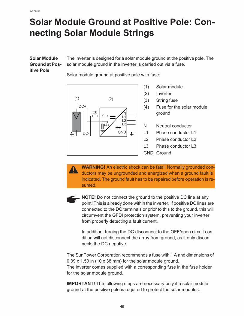
The inverter is designed for a solar module ground at the positive pole. The
solar module ground in the inverter is carried out via a fuse.
Solar module ground at positive pole with fuse:
(1) Solar module
(2) Inverter
(3) String fuse
(4) Fuse for the solar module
ground!
N Neutral conductor
L1 Phase conductor L1
L2 Phase conductor L2
L3 Phase conductor L3
GND Ground
The SunPower Corporation recommends a fuse with 1 A and dimensions of
0.39 x 1.50 in (10 x 38 mm) for the solar module ground.!
The inverter comes supplied with a corresponding fuse in the fuse holder
for the solar module ground.
IMPORTANT! The following steps are necessary only if a solar module
ground at the positive pole is required to protect the solar modules.
DC+
DC- GND
L1N
(1) (2)
=~
=~
(4)L2L3
(3)
WARNING! An electric shock can be fatal. Normally grounded con-
ductors may be ungrounded and energized when a ground fault is
indicated. The ground fault has to be repaired before operation is re-
sumed.
NOTE! Do not connect the ground to the positive DC line at any
point! This is already done within the inverter. If positive DC lines are
connected to the DC terminals or prior to this to the ground, this will
circumvent the GFDI protection system, preventing your inverter
from properly detecting a fault current.
In addition, turning the DC disconnect to the OFF/open circuit con-
dition will not disconnect the array from ground, as it only discon-
nects the DC negative.

50
SunPower
Wire cross
section of so-
lar module
strings
Solar Module
Ground at Pos-
itive Pole:
Connecting
Solar Module
Strings
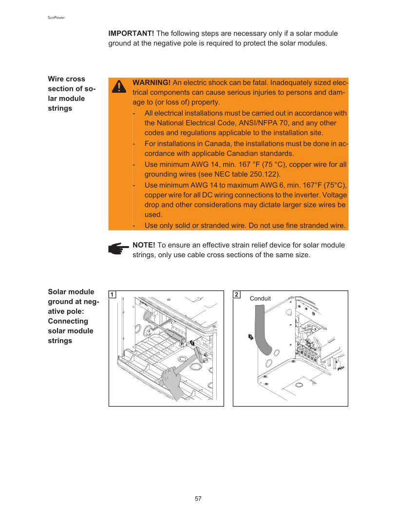
WARNING! An electric shock can be fatal. Inadequately sized elec-
trical components can cause serious injuries to persons and dam-
age to (or loss of) property.
- All electrical installations must be carried out in accordance with
the National Electrical Code, ANSI/NFPA 70, and any other
codes and regulations applicable to the installation site.
- For installations in Canada, the installations must be done in ac-
cordance with applicable Canadian standards.
- Use minimum AWG 14, min. 167 °F (75 °C), copper wire for all
grounding wires (see NEC table 250.122).
- Use minimum AWG 14 to maximum AWG 6, min. 167°F (75°C),
copper wire for all DC wiring connections to the inverter. Voltage
drop and other considerations may dictate larger size wires be
used.
- Use only solid or stranded wire. Do not use fine stranded wire.
NOTE! To ensure an effective strain relief device for solar module
strings, only use cable cross sections of the same size.
1
1
1
Conduit2
NOTE! Use only water tight conduit fittings and conduits. Conduit
fittings and conduits are not part of the scope of supply for the in-
verter.

51
SunPower
The DC Voltage must not exceed
600 V, regardless of temperature.
Tightening torque::!
Stranded wires 1.25 ft. lb.!
Solid wires 0.81 ft. lb.
1
3
1/2 in.
2
4
5 4
6
3
2
1
* Wire for solar module grounding
4
NOTE! Connecting the DC
wiring with the wrong polari-
ty may cause damage to the
inverter. Check both the po-
larity and the open circuit
voltage!

52
SunPower
IMPORTANT!
- Set the jumper from the 'SMON' position to the 'SMOFF' position for cor-
rect measurement results
- Check the polarity and voltage of the solar module strings: the voltage
should be a max. of 600 V, the difference between the individual solar
module strings should be a max. of 10 V.
CAUTION! Danger of damaging the inverter by overload.
- Only connect a maximum of 20 A to an individual DC terminal.
- Connect the DC+ and DC- cables to the correct DC+ and DC-
terminals on the inverter.
1.33 ft. lb.
Tightening torque for solid and stranded
wires
5
1.33 ft. lb.
Tightening torque for solid and stranded
wires
6
NOTE! Form a min. 4 in. wire loop using all wires.
4
1
2 22
3
7
3
1
2
SMON
SMOFF
8
53
SunPower
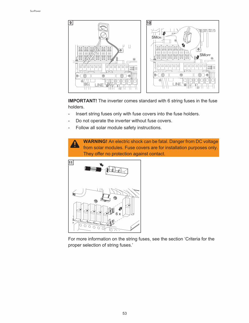
For more information on the string fuses, see the section ‘Criteria for the
proper selection of string fuses.’
9
3
1
2
SMON
SMOFF
10
IMPORTANT! The inverter comes standard with 6 string fuses in the fuse
holders.
- Insert string fuses only with fuse covers into the fuse holders.
- Do not operate the inverter without fuse covers.
- Follow all solar module safety instructions.
WARNING! An electric shock can be fatal. Danger from DC voltage
from solar modules. Fuse covers are for installation purposes only.
They offer no protection against contact.
1
2
6 x
11

54
SunPower
Criteria for the Proper Selection of String
Fuses
DC discon-
nect require-
ments
NEC 690.15-18 allows the use of fuse holders as a suitable means of dis-
connecting PV arrays for servicing.!
Additional DC disconnects external to the inverter may be required by the
local authority having jurisdiction.
General The use of string fuses in the inverter also adds fuse protection to the solar
modules.!
A crucial factor for the fuse protection of solar modules is the maximum
short circuit current Isc of the respective solar module.
Criteria for the
proper selec-
tion of string
fuses
The following criteria must be fulfilled for each solar module string when us-
ing fuse protection:
- IN > 1.56 x ISC
- IN < 2.00 x ISC
- VN >/= 600 V DC
- Fuse dimensions: Diameter 0.41 x 1.38 - 1.50 in. (10.3 x 35 -38 mm)!
IN Nominal current rating of fuse
ISC Short circuit current for standard test conditions (STC) according to
solar module data sheet
VN Nominal voltage rating of fuse
Effects of Us-
ing Underrated
Fuses
In underrated fuses, the nominal current value is less than the short circuit
current of the solar module.!
Effect:!
The fuse may trip in intensive lighting conditions.
NOTE! The string fuse size must not be greater than the maximum
fuse size rating of the PV module as provided on the PV module
manufacturers data sheet. If no maximum fuse size is indicated,
please contact the PV module manufacturer.

55
SunPower
Fuse recom-
mendations
You should only use the following fuses, which have been tested by manu-
facturer, to ensure problem-free fuse protection:
- Littelfuse KLKD fuses
- Cooper Bussmann PV fuses
The manufacturer shall not be liable for any damage or other incidents re-
sulting from the use of other fuses. In addition, all warranty claims are for-
feited.
Application
example
Example: Maximum short circuit current (ISC) of the solar module = 5.75 A
According to the criteria for selecting the correct fuse, the fuse must have a
nominal current greater than 1.56 times the short circuit current:!
5.75 A x 1.56 = 8.97 A
The fuse that should be selected according to the ‘Fuses’ table: !
KLK D 9 with 9.0 A and 600 V AC / DC
NOTE! Only select fuses suitable for a voltage of 600 V DC.

56
SunPower
Solar Module Ground at Negative Pole:
Connecting Solar Module Strings
Solar Module
Ground at
Negative Pole
The inverter is designed for a solar module ground at the positive pole, but
it can also be converted for a ground at the negative pole.!
The solar module ground in the inverter is carried out via a fuse.
Solar module ground at negative pole via fuse:
(1) Solar module
(2) Inverter
(3) String fuse
(4) Fuse for the solar module
ground!
N Neutral conductor
L1 Phase conductor L1
L2 Phase conductor L2
L3 Phase conductor L3
GND Ground
The SunPower Corporation recommends a fuse with 1 A and dimensions of
10 x 38 mm for the solar module ground.!
A corresponding fuse is installed in the fuse holder for the solar module
ground upon delivery.
DC+
GND
L1N
(1) (2)
==~(4)
L2L3
(3)
DC-
WARNING! An electric shock can be fatal. Normally grounded con-
ductors may be ungrounded and energized when a ground fault is
indicated. The ground fault has to be repaired before operation is re-
sumed.
NOTE! Do not connect the ground to the negative DC line at any
point! This is already done within the inverter. If negative DC lines
are connected to the DC terminals or prior to this to the ground, this
will circumvent the GFDI protection system, preventing your inverter
from properly detecting a fault current.
In addition, turning the DC disconnect to the OFF/open circuit con-
dition will not disconnect the array from ground, as it only discon-
nects the DC positive.
57
SunPower
IMPORTANT! The following steps are necessary only if a solar module
ground at the negative pole is required to protect the solar modules.
Wire cross
section of so-
lar module
strings
Solar module
ground at neg-
ative pole:
Connecting
solar module
strings
WARNING! An electric shock can be fatal. Inadequately sized elec-
trical components can cause serious injuries to persons and dam-
age to (or loss of) property.
- All electrical installations must be carried out in accordance with
the National Electrical Code, ANSI/NFPA 70, and any other
codes and regulations applicable to the installation site.
- For installations in Canada, the installations must be done in ac-
cordance with applicable Canadian standards.
- Use minimum AWG 14, min. 167 °F (75 °C), copper wire for all
grounding wires (see NEC table 250.122).
- Use minimum AWG 14 to maximum AWG 6, min. 167°F (75°C),
copper wire for all DC wiring connections to the inverter. Voltage
drop and other considerations may dictate larger size wires be
used.
- Use only solid or stranded wire. Do not use fine stranded wire.
NOTE! To ensure an effective strain relief device for solar module
strings, only use cable cross sections of the same size.
1
1
1
Conduit2

58
SunPower
Tightening torque!
Stranded wires 1.25 ft. lb.!
Solid wires 0.81 ft. lb.
After disconnecting the DC main
switch cable:
- Connect the DC+ cable to the
DC- connection as per step 6
- Connect the DC- cable to the
DC+ connection as per step 6
- Identify the reversed polarity as
per steps 7 and 8 with (+) and
(-).
1
3
1/2 in.
2
4
5 4
6
3
2
1
* Wire for solar module grounding
4
3
2
4
1
DC
DC
-
+
5
DC
DC
-
+
4
5
32
1
1
6DC
DC
-
+
1
2
7

59
SunPower
IMPORTANT! Additional to chan-
ging polarity of the DC main switch
wires the inverter must be set for a
solar module ground at the negative
pole according to section "Commis-
sioning" (Setting the inverter for so-
lar module ground at negative pole)
at commissioning.
The DC Voltage must not exceed
600 V, regardless of temperature.
DC
DC
+
-
1
2
8
NOTE! Connecting the DC
wiring with the wrong polari-
ty may cause damage to the
inverter. Check both the po-
larity and the open circuit
voltage.
CAUTION! Danger of damaging the inverter by overload.
- Only connect a maximum of 20 A to an individual DC terminal.
- Connect the DC+ wire to the left connection of the inverter's DC
terminals.
- Connect the DC- wire to the right connection of the inverter's DC
terminals.
- Identify the reversed polarity as per step 11 with (+) and (-).

60
SunPower
IMPORTANT!
- Set the jumper from the 'SMON' position to the 'SMOFF' position for cor-
rect measurement results
- Check the polarity and voltage of the solar module strings: the voltage
should be a max. of 600 V, the difference between the individual solar
module strings should be a max. of 10 V.
DC+
2
DC-
1
DC+
1.33 ft. lb.
Tightening torque for solid and stranded
wires
DC - DC +
9
3
2
DC-1
DC+
1.33 ft. lb.
Tightening torque for solid and stranded
wires
DC - DC +
10
DC-DC+
DC - DC +
DC-
DC
DC-DC+
DC + DC -
DC + DC
+
-
1
3
2
4
11
4
1
2 22
3
12
3
1
2
SMON
SMOFF
13
DC+ DC-
14

61
SunPower
IMPORTANT! The inverter comes standard with 6 string fuses in the fuse
holders.
- Insert string fuses only with fuse covers into the fuse holders.
- Do not operate the inverter without fuse covers.
- Follow all solar module safety instructions.
For more information on the string fuses, see the section "Criteria for the
proper selection of string fuses."
3
1
2
SMON
SMOFF
15
WARNING! An electric shock can be fatal. Danger from DC voltage
from solar modules. Fuse covers are for installation purposes only.
They offer no protection against contact.
1
2
6 x
16
62
SunPower
Criteria for the Proper Selection of String
Fuses
DC discon-
nect require-
ments
NEC 690.15-18 allows the use of fuse holders as a suitable means of dis-
connecting PV arrays for servicing.!
Additional DC disconnects external to the inverter may be required by the
local authority having jurisdiction.
General The use of string fuses in the inverter also adds fuse protection to the solar
modules.!
A crucial factor for the fuse protection of solar modules is the maximum
short circuit current Isc of the respective solar module.
Criteria for the
proper selec-
tion of string
fuses
The following criteria must be fulfilled for each solar module string when us-
ing fuse protection:
- IN > 1.56 x ISC
- IN < 2.00 x ISC
- VN >/= 600 V DC
- Fuse dimensions: Diameter 0.41 x 1.38 - 1.50 in. (10.3 x 35 -38 mm)!
IN Nominal current rating of fuse
ISC Short circuit current for standard test conditions (STC) according to
solar module data sheet
VN Nominal voltage rating of fuse
Effects of Us-
ing Underrated
Fuses
In underrated fuses, the nominal current value is less than the short circuit
current of the solar module.!
Effect:!
The fuse may trip in intensive lighting conditions.
NOTE! The string fuse size must not be greater than the maximum
fuse size rating of the PV module as provided on the PV module
manufacturers data sheet. If no maximum fuse size is indicated,
please contact the PV module manufacturer.

63
SunPower
Fuse recom-
mendations
You should only use the following fuses, which have been tested by manu-
facturer, to ensure problem-free fuse protection:
- Littelfuse KLKD fuses
- Cooper Bussmann PV fuses
The manufacturer shall not be liable for any damage or other incidents re-
sulting from the use of other fuses. In addition, all warranty claims are for-
feited.
Application
example
Example: Maximum short circuit current (ISC) of the solar module = 5.75 A
According to the criteria for selecting the correct fuse, the fuse must have a
nominal current greater than 1.56 times the short circuit current:!
5.75 A x 1.56 = 8.97 A
The fuse that should be selected according to the ‘Fuses’ table: !
KLK D 9 with 9.0 A and 600 V AC / DC
NOTE! Only select fuses suitable for a voltage of 600 V DC.
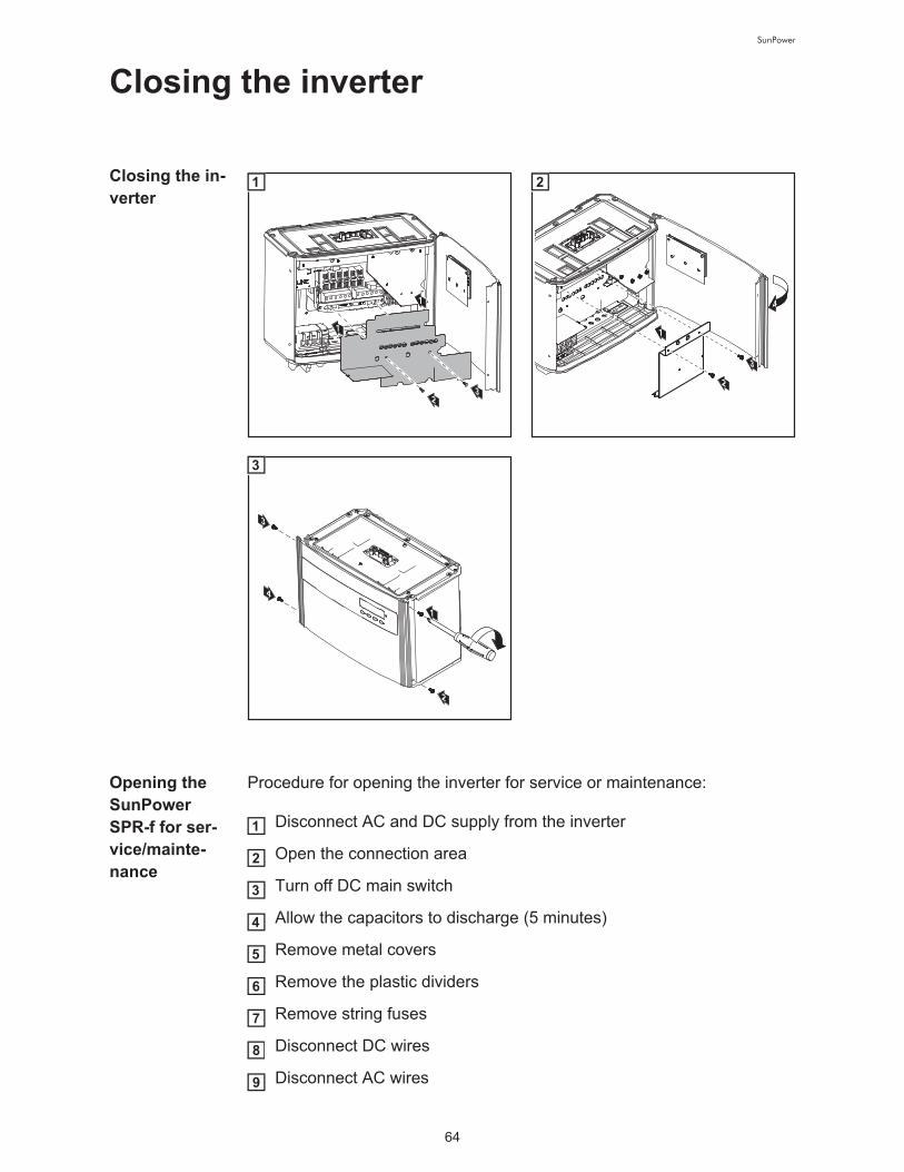
64
SunPower
Closing the inverter
Closing the in-
verter
Opening the
SunPower
SPR-f for ser-
vice/mainte-
nance
Procedure for opening the inverter for service or maintenance:
Disconnect AC and DC supply from the inverter
Open the connection area
Turn off DC main switch
Allow the capacitors to discharge (5 minutes)
Remove metal covers
Remove the plastic dividers
Remove string fuses
Disconnect DC wires
Disconnect AC wires
1
1
32
1
4
1
2
3
2
3
2
4
1
3
1
2
3
4
5
6
7
8
9

65
SunPower
Commissioning
Factory pre-
set configura-
tion
The inverter has been pre-configured in the factory and is ready for opera-
tion. You only have to set the available power grid for startup.
To change your inverter settings, please see section ‘The setup menu’ in
the chapter ‘Operation.’
Requirements
for start-up op-
eration
- Inverter connected to the public grid (AC)
- Inverter connected to solar modules (DC)
- 3 plastic dividers inserted
- 2 metal covers mounted
- Power stage set mounted
Commission-
ingTurn on AC disconnect
Flip DC main switch to position -
1 -
As soon as the photovoltaic mo-
dules produce sufficient power, the
Operating Status LED lights up
orange.
The orange LED indicates that the
feed-in mode of the inverter will be-
gin shortly.
The screen displays the startup pha-
se.!
- Segment test
All display elements light up for
about one second.
NOTE! Do not operate the inverter without fuse covers.
off
on
1
ON
AC
21
2

66
SunPower
- The inverter goes through a
master check list for several se-
conds.
The display shows ‘TEST’ and
indicates the respective compo-
nent that is being tested (for ex-
ample, ‘LED’).
- The grid selection phase begins:
'SETUP SEL' is shown.!
Press the ‘Enter’ key
The first grid selection option is
shown (e.g., 208 V).!
Select the grid
Selecting the
grid
Several grid selection options are displayed depending on the product type
(see also section 'Connecting the SunPower SPR-f to the public grid’).
Use the ‘Up’ and ‘Down’ keys to select the desired grid:
3
4
Grid voltage 208 V Delta!
No neutral conductor in the system!
Neutral conductor monitoring is de-
activated
1
120
° 120 °
120 °
208
V 208 V
208 V
L1
L2L3
=
~
=
~
=
~

67
SunPower
Grid voltage 208 V Delta: 120 V
WYE!
Neutral conductor available in the
system!
Neutral conductor monitoring is ac-
tivated
Grid voltage 240 V Delta!
No neutral conductor in the system!
Neutral conductor monitoring is de-
activated
12
0 V
120 V 120 V
120
° 120 °
120 °
208 V
208 V
208 V
L1
L2
N
L3
=
~
=
~
=
~
240 V24
0 V
240 V
120
° 120 °
120 °
L1
L2L3
=
~
=
~
=
~
240 V24
0 V12
0 ° 12
0 °
120 °
120 V120 V
L3
L1
N
L2
=
~
=
~
=
~

68
SunPower
Press the 'Enter' key 2x to confirm your grid selection (or use the 'Esc'
key to return to grid selection)
The startup phase restarts with the segment test.
Grid voltage 240 V: 120 V Stinger!
Neutral conductor available in the
system!
Neutral conductor monitoring is ac-
tivated
Grid voltage 240 V: 120 V Split
Phase!
Neutral conductor available in the
system!
Neutral conductor monitoring is ac-
tivated
Grid voltage 480 V Delta: 277 V
WYE!
Neutral conductor available in the
system!
Neutral conductor monitoring is ac-
tivated
240 V24
0 V12
0 ° 12
0 °
120 °
120 V120 V
L3
L1
N
L2
=
~
=
~
=
~
180 °
120 V 120 V
240 V
2L1LN
=
~
27
7 V
277 V
277 V
120
° 120 °
120 °
480
V
480V
480 V
L1
L2
N
L3
=
~
=
~
=
~
2

69
SunPower
Setting the in-
verter for solar
module
ground at neg-
ative pole The following 5-digit access code must be entered to access the "Basic Ser-
vice" menu: 22742.
"Menu" is shown.!
Select the "Setup" mode using
the "Left" or "Right" keys
Press the unoccupied "Esc" key
5 x
"CODE" is displayed, the first digit
flashes.!
Enter the access code 22742:
Use the "Up" and "Down" keys
to select a value for the first digit
of the access code
Press the "Enter" key
The second digit flashes.!
Repeat steps 5 and 6 for the se-
cond, third, fourth and fifth digit
of the access code until ...
NOTE! After the inverter is switched on, the corresponding ground-
ing method must be set in the "Basic Service" menu if a solar mod-
ule ground at the negative pole is required.
Confirm any status codes dis-
played by pressing the "Enter"
key
Press the "Menu" key
1
2
3
4
5
6
7
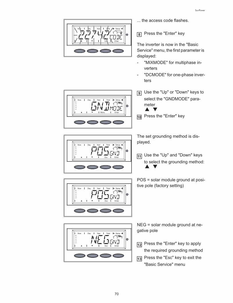
70
SunPower
... the access code flashes.!
Press the "Enter" key
The inverter is now in the "Basic
Service" menu, the first parameter is
displayed:
- "MIXMODE" for multiphase in-
verters
- "DCMODE" for one-phase inver-
ters
Use the "Up" or "Down" keys to
select the "GNDMODE" para-
meter
Press the "Enter" key
The set grounding method is dis-
played.!
Use the "Up" and "Down" keys
to select the grounding method:
POS = solar module ground at posi-
tive pole (factory setting)
NEG = solar module ground at ne-
gative pole!
Press the "Enter" key to apply
the required grounding method
Press the "Esc" key to exit the
"Basic Service" menu
8
9
10
11
12
13

71
SunPower
Startup phase
during startup
operation
- Segment test!
All display elements light up for
about one second.
- The inverter goes through a
master check list for several se-
conds. !
The display shows ‘TEST’ and
indicates the respective compo-
nent that is being tested (for ex-
ample, ‘LED’)
- ‘TEST COM’ is shown.
- Synchronization with grid: !
‘WAIT PS’ is displayed, the in-
verter icon flashes: the inverter
is waiting for all power stage
sets in the network to be on
stand-by. This procedure takes
place dependent on the DC vol-
tage.
- Next, the display shows ‘SYNC
AC,’ the grid icon flashes.

72
SunPower
- Startup test: !
Before the inverter starts fee-
ding energy into the grid, the
conditions of the grid are tested
in detail in accordance with local
regulations. The display shows
‘START UP.’
- Operation of feeding energy into
the grid: !
After selecting the grid and
when the tests are concluded,
the inverter starts feeding ener-
gy into the grid. !
The display shows the present
power feeding into the grid. !
The Operating Status LED lights
up green, and the inverter starts
operating.
IMPORTANT! For more information about the startup phase, please see
the chapter 'Operation', section 'Product description SunPower SPR-f'
(Startup phase, Test procedure).

SunPower
Operation

74
SunPower
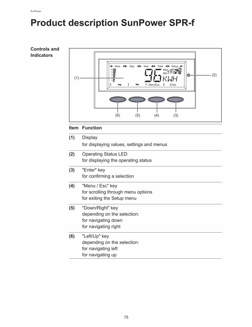
75
SunPower
Product description SunPower SPR-f
Controls and
Indicators
Item Function
(1) Display
for displaying values, settings and menus
(2) Operating Status LED!
for displaying the operating status
(3) "Enter" key!
for confirming a selection
(4) "Menu / Esc" key!
for scrolling through menu options!
for exiting the Setup menu
(5) "Down/Right" key!
depending on the selection:!
for navigating down!
for navigating right
(6) "Left/Up" key!
depending on the selection:!
for navigating left!
for navigating up
(1)
(6) (5) (4) (3)
(2)

76
SunPower
Display The display unit's power is supplied via the safety-low voltage of the solar
modules, which means that the display unit can be used in the daytime.
IMPORTANT! The inverter display is not a calibrated measuring instru-
ment. A slight inaccuracy of a few percent is intrinsic to the system. A cali-
brated meter will be needed to make calculations for the power supply
company.
Item Function
(1) Icons for the "Now" display mode
(2) Icons for the "Day" display mode
(3) Icons for the "Year" display mode
(4) Icons for the "Total" display mode
(5) Icons for the "Setup" display mode
(6) Icons for operating conditions
The value shown represents the maximum value within
the period of observation (depending on which display
mode is selected).
The value shown represents the minimum value within the
period of observation (depending on which display mode
is selected).
Important The minimum and maximum values displayed
do not represent the absolute extreme values, because
data is recorded only at two-second intervals.
... appears when values are displayed which are directly
associated with the solar modules
(11) (10)
(3) (4) (5)
(6)
(7)
(13)
(12)
(9) (8)
(1) (2)

77
SunPower
Operating Sta-
tus LEDPosition of Operating Status LED on
the inverter
Depending on the operating status,
the Operating Status LED assumes
different colors:
... appears when values are displayed which are directly
associated with the public grid
... appears with data readings that are directly related to
the inverter
(7) Range for display unit!
for displaying the applicable measuring unit
(8) Icon for the "Enter" key
(9) Icons for the "Menu/Esc" key
(10) Icons for the "Down/Right" key
(11) Icons for the "Left/Up" key
(12) Range for display value!
for displaying the value
(13) Output bar (not active during setup)!
indicates the output power fed into the grid at a given moment - re-
gardless of the display mode chosen. The screen displays % of the
maximum possible output power of your solar inverter
Item Function
Operating Status
LED
Explanation
Steady green The LED stays lit after the automatic startup phase of
the inverter as long as power is being fed into the
grid.!
It indicates problem-free operation of the photovolta-
ic system.

78
SunPower
A list of most status codes, the corresponding status information, their sta-
tus causes and repair measures can be found in the chapter "Troubleshoot-
ing and Maintenance," section "Status Diagnosis and Troubleshooting."
Flashing green The photovoltaic system is working correctly, a status
code is on the display.
When a status code is shown, rectify the relevant
condition by going to the "Maintenance and Service"
chapter, "Status Diagnosis and Troubleshooting"
section. The status code can be acknowledged by
pressing the "Enter" key.
Steady orange The inverter enters an automatic startup phase as
soon as the solar modules are delivering sufficient
power after sunrise.
Flashes orange A warning is shown on the display !
or!
the inverter has been set to standby operation in the
Setup menu (= manual shutoff of operation).
The next day, operation will resume automatically.
During the time the LED flashes orange, operation
can be resumed manually at any time (see section
"The Setup Menu")
Steady red General status: the respective status code is shown
on the screen
Remains dark There is no connection to the solar modules, !
no solar module power due to darkness.
Operating Status
LED
Explanation

79
SunPower
Startup Phase and Grid Feed-in Mode
Startup phase The inverter carries out a self test after being turned on automatically. Then
a test of the public grid is carried out. This test takes five minutes. During
the startup sequence the illumination of the Operating Status LED is yellow.
Test proce-
dure
1. Segment test!
All display elements light up for about one second
2. Self test of essential inverter components
- The inverter goes through a master check list for several seconds
- The display shows ‘TEST’ and indicates the respective component
that is being tested (for example, ‘LED’)
3. Synchronization with grid:
- ‘WAIT PS’ is displayed, the inverter icon flashes: The inverter is
waiting for all power stage sets in the network to be on stand-by.
This procedure takes place dependent on the DC voltage
- Next, the display shows ‘SYNC AC,’ the grid icon flashes.
4. Startup test
- Before the inverter starts feeding energy into the grid, the conditions
of the grid are tested in accordance with local regulations.

80
SunPower
- The display shows ‘START UP.’
!
The startup test takes five minutes. The time elapsed is indicated by a
bar shrinking from the top down.
!
Whenever two scale divisions stop flashing and disappear, 1/10 of the
total duration of the test is over.
Operation of
Feeding Ener-
gy into the
Grid
- Once the tests have been completed, the inverter starts feeding power
into the grid.
- The display shows the present power feeding into the grid.
- The Operating Status LED lights up green, and the inverter starts oper-
ating.
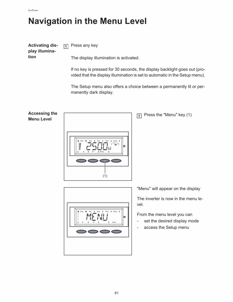
81
SunPower
Navigation in the Menu Level
Activating dis-
play illumina-
tion
Press any key!
!
The display illumination is activated.!
!
If no key is pressed for 30 seconds, the display backlight goes out (pro-
vided that the display illumination is set to automatic in the Setup menu).!
!
The Setup menu also offers a choice between a permanently lit or per-
manently dark display.
Accessing the
Menu LevelPress the "Menu" key (1)
"Menu" will appear on the display
The inverter is now in the menu le-
vel.
From the menu level you can
- set the desired display mode
- access the Setup menu
1
(1)
1

82
SunPower
The Display Modes
Display modes
Selecting a
display modeAccess the menu level
Use the "left" (7) or "right" (6)
keys to select your preferred dis-
play mode (1) - (4)
Press "Enter" (5)
The selected display mode is
shown, e.g., "Day" display mode.!
"Now" display mode .....
.
shows current data !
"Day" display mode .....
.
shows data for the current day !
"Total" display mode .....
.
shows data since your inverter first started op-
erating
(7)
(1) (2) (3) (4)
(6) (5)
1
2
3
IMPORTANT! The "Year" menu
item is not available.

83
SunPower
Overview of
display values
x Optional !
If the required option card is not available, "N.A." (not available) is
displayed.
Display
mode
Icon Unit Optional Display value
"Now" W - Output power
V - AC grid voltage
A - Output current
Hz - Grid frequency
V - Solar module voltage
A - Solar module current
- - GFDI Status
- - NLMON Communication
HH:MM x Time
"Day" kWh /
MWh
- Output energy
"Total" Currency - Yield
kg / T - CO2 reduction
W - Maximum output power
V - Maximum grid voltage
V - Minimum grid voltage
V - Maximum solar module volt-
age
HH:MM - Operating hours of the invert-
er
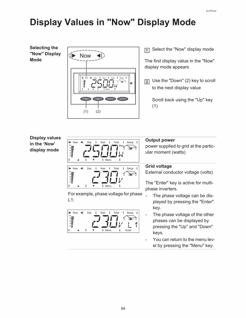
84
SunPower
Display Values in "Now" Display Mode
Selecting the
"Now" Display
Mode
Select the "Now" display mode
The first display value in the "Now"
display mode appears!
Use the "Down" (2) key to scroll
to the next display value!
!
Scroll back using the "Up" key
(1)
Display values
in the ‘Now’
display mode
(1) (2)
1
2
Output power!
power supplied to grid at the partic-
ular moment (watts)
For example, phase voltage for phase
L1:
Grid voltage!
External conductor voltage (volts)
The "Enter" key is active for multi-
phase inverters.
- The phase voltage can be dis-
played by pressing the "Enter"
key.
- The phase voltage of the other
phases can be displayed by
pressing the "Up" and "Down"
keys.
- You can return to the menu lev-
el by pressing the "Menu" key.

85
SunPower
For example, phase current for phase
L3:
Output current !
current supplied to the grid at the
particular moment (amperes)
The "Enter" key is active for multi-
phase inverters.
- The phase current can be dis-
played by pressing the "Enter"
key.
- The phase current of the other
phases can be displayed by
pressing the "Up" and "Down"
keys.
- You can return to the menu lev-
el by pressing the "Menu" key.
Grid frequency !
(hertz)
Solar module voltage!
voltage of the solar modules at the
moment of data display (volts)
Solar module current!
current supplied by solar modules
at the moment of data display (am-
peres)
GFDI status!
If there is no ground fault in the
system, ‘GFDI OK’ is displayed
NL-MON communication!
When there is communication with
the ‘NL-MON’ plug-in card, ‘NLM-
ON OK’ is displayed

86
SunPower
"N.A." - dis-
play value not
available
The display "N.A." indicates that the display value is not available. The icon
and the unit of the display value are also shown on the display along with
"N.A." (not available).
Example: unavailable display value for solar module temperature

87
SunPower
Display values in the Day / Total display
modes
General For the inverter, the day begins when it switches on. If the DC supply line is
disconnected, the following parameters within the ‘Day’ display mode will
be re-set after repeating the start-up:
- yield (currency can be selected)
- CO2 reduction (lbs.)
- maximum output power (watts)
- maximum grid voltage (volts)
- minimum grid voltage (volts)
- operating hours of the inverter
Selecting "Day
/ Total" display
modes
Select the "Day" or !
"Total" display mode
The first display value appears in the selected display mode.
Use the "Down" key (2) to scroll to the next display value !
!
use the "Up" key (1) to scroll back
First display value in the "Day" dis-
play mode:
First display value in the "Total"
display mode:
(1) (2) (1) (2)
1
2
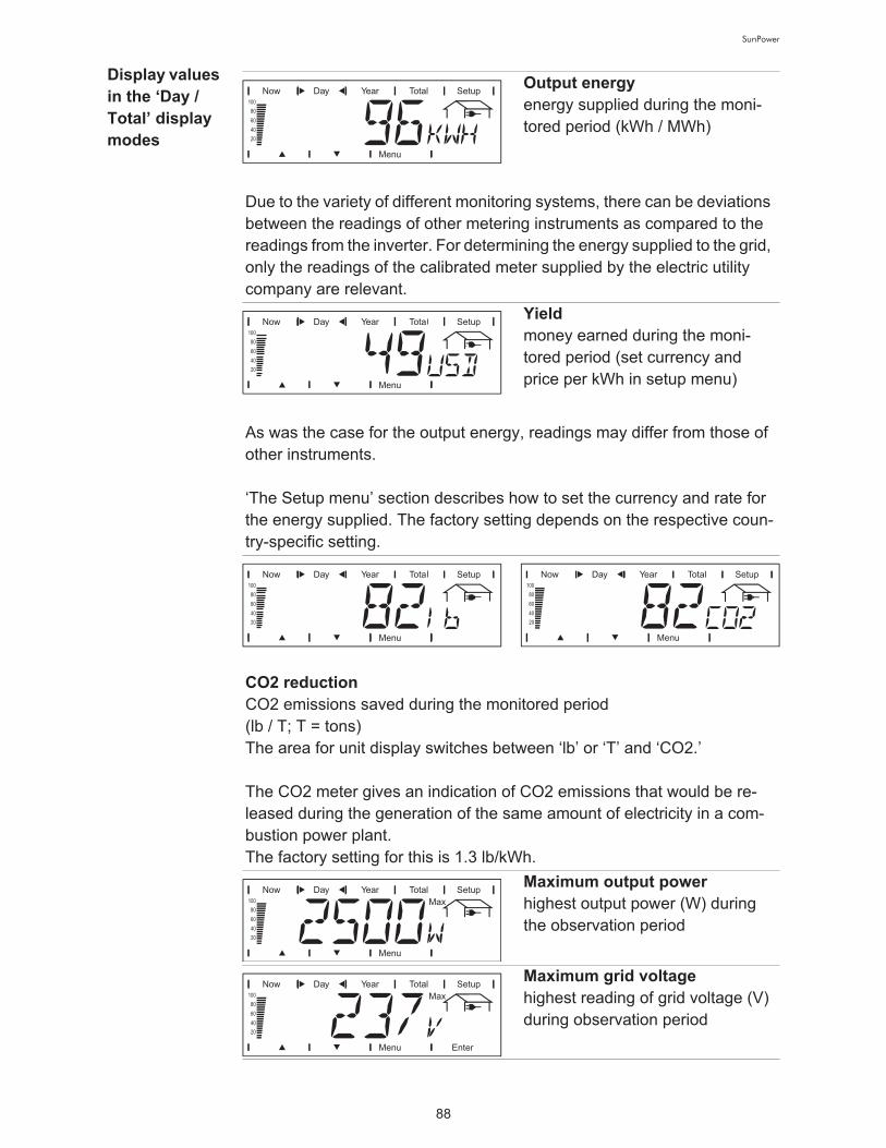
88
SunPower
Display values
in the ‘Day /
Total’ display
modes
Output energy!
energy supplied during the moni-
tored period (kWh / MWh)
Due to the variety of different monitoring systems, there can be deviations
between the readings of other metering instruments as compared to the
readings from the inverter. For determining the energy supplied to the grid,
only the readings of the calibrated meter supplied by the electric utility
company are relevant.
Yield!
money earned during the moni-
tored period (set currency and
price per kWh in setup menu)
As was the case for the output energy, readings may differ from those of
other instruments. !
!
‘The Setup menu’ section describes how to set the currency and rate for
the energy supplied. The factory setting depends on the respective coun-
try-specific setting.
!
CO2 reduction!
CO2 emissions saved during the monitored period !
(lb / T; T = tons) !
The area for unit display switches between ‘lb’ or ‘T’ and ‘CO2.’ !
!
The CO2 meter gives an indication of CO2 emissions that would be re-
leased during the generation of the same amount of electricity in a com-
bustion power plant. !
The factory setting for this is 1.3 lb/kWh.
Maximum output power!
highest output power (W) during
the observation period
Maximum grid voltage !
highest reading of grid voltage (V)
during observation period

89
SunPower
"N.A." - dis-
play value not
available
The display "N.A." indicates that the display value is not available. The icon
and the unit of the display value are also shown on the display along with
"N.A." (not available).
Example: unavailable display value for solar module temperature
Minimum grid voltage !
lowest reading of grid voltage (V)
during observation period
Maximum solar module voltage!
highest reading of solar module
voltage (V) during the observation
period
Operating hours !
indicates how long the inverter has
been operating !
(HH:MM)
Duration of operation is shown in hours and minutes up to 999 h and 59
min (display: ‘999:59’). After that only full hours are displayed. !
!
Although the inverter does not operate during the night, all sensor data are
recorded around the clock.

90
SunPower
The Setup Menu
Presetting The inverter is pre-configured and ready to use. No manual control is nec-
essary for feeding the power it generates into the grid.
The setup menu allows easy readjustment of the inverter's preset parame-
ters to your needs.
Accessing the
Setup MenuSwitch to the menu level (press
the "Menu" key)
Select the "Setup" (1) mode
using the "Left" (4) or "Right" (3)
keys
Press "Enter" (2)
The Setup Menu’s first menu item
"STANDBY" is shown.
(4) (3) (2)
(1)
1
2
3

91
SunPower
Scrolling
through Menu
Items
Access the Setup menu
Scroll through the available menu items using the "Up" (1) and "Down"
(2) keys
Example: "STANDBY" menu item! Example: "CONTRAST" menu
item
(1) (2) (1) (2)
1
2
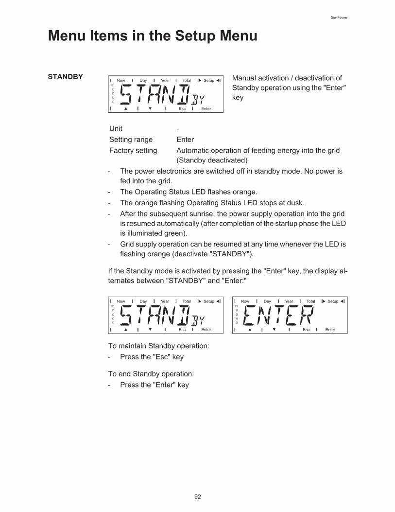
92
SunPower
Menu Items in the Setup Menu
STANDBY Manual activation / deactivation of
Standby operation using the "Enter"
key
- The power electronics are switched off in standby mode. No power is
fed into the grid.
- The Operating Status LED flashes orange.
- The orange flashing Operating Status LED stops at dusk.
- After the subsequent sunrise, the power supply operation into the grid
is resumed automatically (after completion of the startup phase the LED
is illuminated green).
- Grid supply operation can be resumed at any time whenever the LED is
flashing orange (deactivate "STANDBY").
If the Standby mode is activated by pressing the "Enter" key, the display al-
ternates between "STANDBY" and "Enter:"
To maintain Standby operation:
- Press the "Esc" key
To end Standby operation:
- Press the "Enter" key
Unit -
Setting range Enter
Factory setting Automatic operation of feeding energy into the grid
(Standby deactivated)

93
SunPower
CONTRAST Contrast setting on LCD display
Since contrast depends on temperature, it may be necessary to adjust the
"CONTRAST" menu item when ambient conditions change.
LIGHT MODE Initial setting for display illumination.
CASH Setting of currency and rate for in-
voicing the energy supplied
Unit -
Setting range 0 - 7
Factory setting 7
Unit -
Setting range AUTO / ON / OFF
Factory setting AUTO
AUTO: The display illumination will stop 30 seconds after the
last time a key has been pressed.
ON: The display will remain illuminated whenever power
is supplied to the grid.
OFF: The display illumination will be permanently off.
IMPORTANT! The "LIGHT MODE" setting only relates to the display's
background illumination. The LCD display will still remain on during opera-
tion. Its energy consumption is less than one mW (1/1000 W).
Unit -
Display area Currency / Charge rate/kWh
Factory setting USD

94
SunPower
CO2 Setting of CO2 reduction factor
YIELD
OFF SET!
Preset value for the output energy, added to the actual output energy (e.g.,
transfer value upon replacement of the inverter) and the SI prefix
CALI.!
Preset correction value, so that the data shown on the inverter display cor-
responds to the calibrated data shown on the electric meter
Unit lb/kWh, T/kWh
Setting range 00,01 - 99,99
Factory setting 1.3
Setting
- an OFFSET value for the total
energy display
- a measurement correction val-
ue for the Day, Year and Total
energy display
Setting range OFF SET / CALI.
Unit Wh / kWh / MWh
Setting range 5-digit + k... / M...!
!
1 kWh = 1000 Wh!
1 MWh = 1000000 Wh
Factory setting 0
Unit %
Setting range -5.0 - +5.0 in increments of 0.1
Factory setting 0

95
SunPower
IG no. Number setting (address) of the in-
verter in a setup comprising multiple
solar inverters linked together
DAT COM Data connection check
STATE PS Status display of power stage sets;
the last error that has occurred can
be displayed
Unit -
Setting range 01 - 99 (100th inverter = 00)
Factory setting 1
IMPORTANT! Each inverter must be assigned its own address when con-
necting several inverters in a data communications system.
Unit -
Setting range OK COM or ERROR COM displays
Factory setting -
IMPORTANT! Due to the low level of irradiance early in the morning and in
the evening, the status codes 306 (power low) and 307 (DC low) are dis-
played routinely at these times of day. These status messages do not indi-
cate any kind of fault.
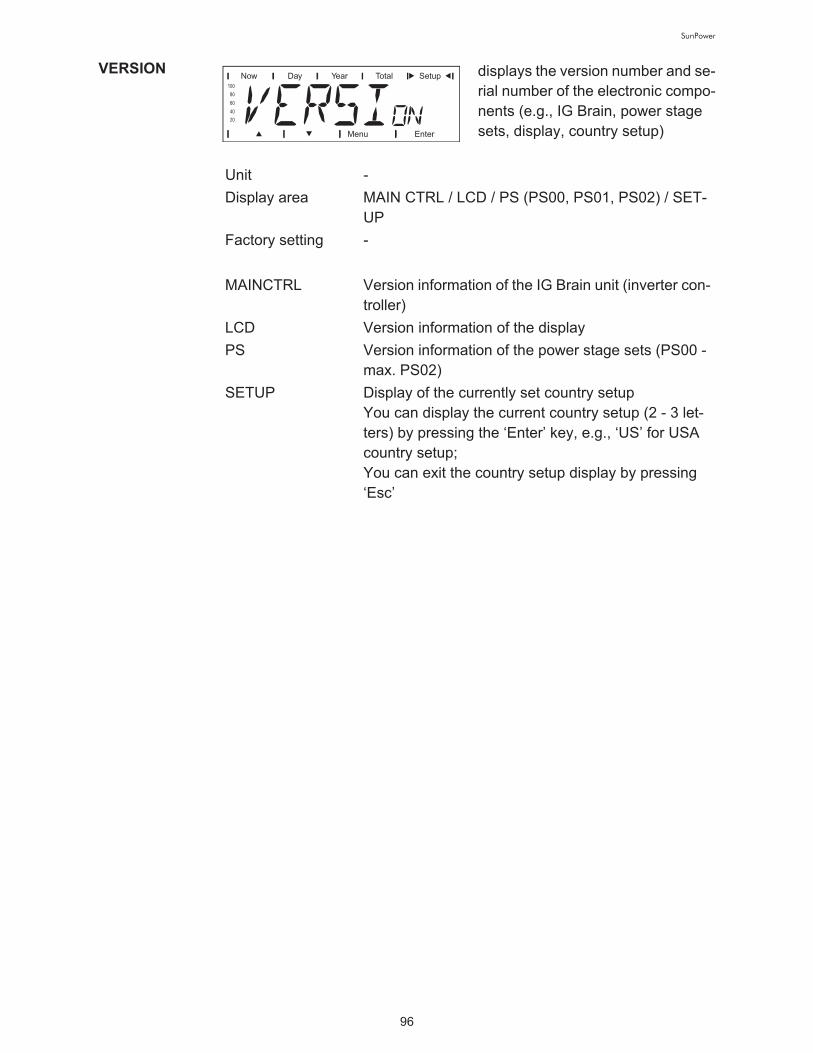
96
SunPower
VERSION displays the version number and se-
rial number of the electronic compo-
nents (e.g., IG Brain, power stage
sets, display, country setup)
Unit -
Display area MAIN CTRL / LCD / PS (PS00, PS01, PS02) / SET-
UP
Factory setting -
MAINCTRL Version information of the IG Brain unit (inverter con-
troller)
LCD Version information of the display
PS Version information of the power stage sets (PS00 -
max. PS02)
SETUP Display of the currently set country setup!
You can display the current country setup (2 - 3 let-
ters) by pressing the ‘Enter’ key, e.g., ‘US’ for USA
country setup;!
You can exit the country setup display by pressing
‘Esc’

97
SunPower
Setting and Displaying Menu Items
Setting Menu
Items - General
Access the Setup menu
Use the "Up" or "Down" keys to select the desired menu item
Press the "Enter" key
The first digit of a value to be
set flashes:
The available settings are dis-
played:
Use the "Up" and "Down" keys
to select a value for the first
digit
Press the "Enter" key
The second digit of the value flash-
es.
Repeat steps 4 and 5 until ...
the entire value flashes.
Press the "Enter" key
Repeat steps 4 - 6 for units or
other values to be set until the
unit or value flashes.
Press the "Enter" key to save
and apply the changes.!
!
Press the "Esc" key to not save
the changes.!
Use the "Up" and "Down" keys
to select the desired setting
Press the "Enter" key to save
and apply the selection.!
!
Press the "Esc" key to not save
the selection.
The currently selected menu item
is displayed.
The currently selected menu item
is displayed.
1
2
3
4
5
6
7
8
9
4
5

98
SunPower
Application
example: set-
ting the cur-
rency and rate
Select the ‘CASH’ menu item
Press the ‘Enter’ key
The currency is display, factory set-
ting = ‘USD’; !
The first character flashes. !
Use the ‘Up’ and ‘Down’ keys to
select a letter for the first cha-
racter
Press the ‘Enter’ key
The second character flashes. !
Use the ‘Up’ and ‘Down’ keys to
select a letter for the second
character
Press the ‘Enter’ key
The third character flashes. !
Use the ‘Up’ and ‘Down’ keys to
select a letter for the third cha-
racter
Press the ‘Enter’ key
The set currency flashes. !
Press the ‘Enter’ key
1
2
3
4
5
6
7
8
9

99
SunPower
The rate for energy supplied is now
displayed in kWh / currency, factory
setting = 0.14 USD / kWh; !
The first digit flashes. !
Use the ‘Up’ and ‘Down’ keys to
select a value for the first digit
(e.g., 0)
The second digit flashes. !
Use the ‘Up’ and ‘Down’ keys to
select a value for the second di-
git (e.g., 0)
Press the ‘Enter’ key
The first digit after the decimal point
flashes. !
Use the ‘Up’ and ‘Down’ keys to
select a value for the first digit
after the decimal point (e.g., 4)
Press the ‘Enter’ key
The second digit after the decimal
point flashes. !
Use the ‘Up’ and ‘Down’ keys to
select a value for the second di-
git after the decimal point (e.g.,
8)!
The values that can be set range
from 00.01 to 99.99.
Press the ‘Enter’ key
10
Press the ‘Enter’ key11
12
13
14
15
16
17
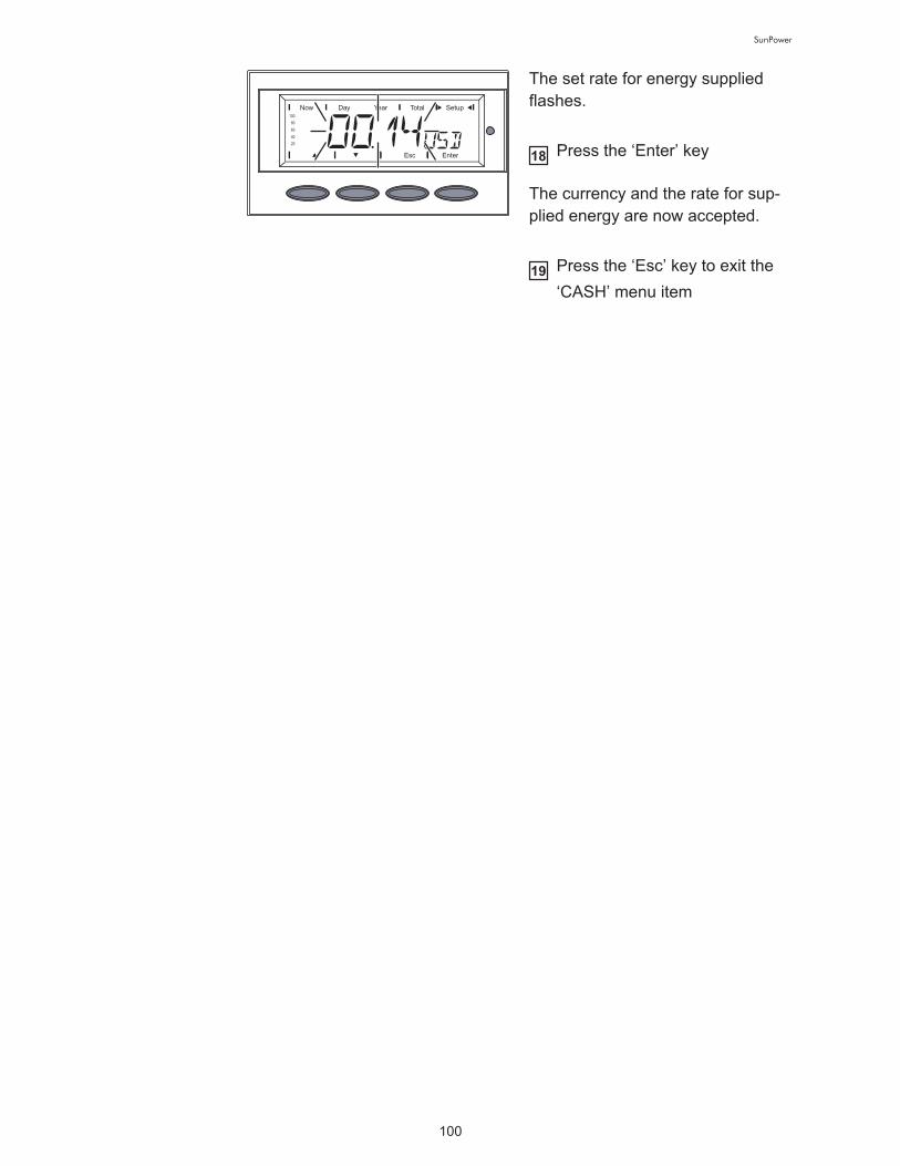
100
SunPower
The set rate for energy supplied
flashes. !
Press the ‘Enter’ key
The currency and the rate for sup-
plied energy are now accepted. !
Press the ‘Esc’ key to exit the
‘CASH’ menu item
18
19

SunPower
Troubleshooting and Mainte-nance

102
SunPower

103
SunPower
Status Diagnosis and Troubleshooting
Displaying
Status Codes
Your inverter is equipped with a self diagnostic system that automatically
identifies a large number of possible operation issues by itself and displays
them on the screen. This enables you to know immediately if there are any
malfunctions in the inverter, the photovoltaic system or any installation or
operating errors.
Whenever the self diagnostic system has identified a particular issue, the
respective status code is shown on the screen.
Normal Opera-
tion Status
Codes
Total failure If the display remains dark for a long time after sunrise:
- Check the open circuit voltage of the solar modules at the connections
of inverter:
Open circuit voltage < 265 V ... Error in the photovoltaic system
Open circuit voltage > 265 V ... may indicate a basic fault in the inverter.
In this case, notify a trained service technician.
IMPORTANT! Status codes may sometimes appear briefly as a result of
the control response from the inverter. If it subsequently continues to oper-
ate normally, there has not been a system error.
The open circuit voltage of the so-
lar modules is too low.
As soon as the open circuit voltage exceeds 265 V, the inverter starts syn-
chronizing with the grid (display shows "SYNC AC").
The total power output of the solar
modules is insufficient.
After a short time the inverter resumes grid synchronization (display shows
"SYNC AC").
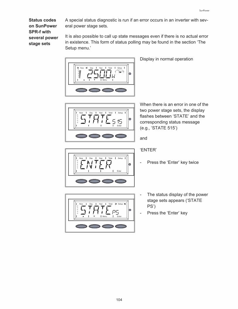
104
SunPower
Status codes
on SunPower
SPR-f with
several power
stage sets
A special status diagnostic is run if an error occurs in an inverter with sev-
eral power stage sets.
It is also possible to call up state messages even if there is no actual error
in existence. This form of status polling may be found in the section ‘The
Setup menu.’
Display in normal operation
When there is an error in one of the
two power stage sets, the display
flashes between ‘STATE’ and the
corresponding status message !
(e.g., ‘STATE 515’)
and
‘ENTER’ !
- Press the ‘Enter’ key twice
- The status display of the power
stage sets appears (‘STATE
PS’)
- Press the ‘Enter’ key

105
SunPower
Class 1 Status
CodesClass 1 status codes are typically
temporary. Their cause lies in the
public grid.
The initial response of the inverter is to disconnect itself from the grid. The
grid is subsequently checked for the stipulated monitoring period. If after the
end of this period no further defect is identified, your inverter resumes op-
erating and feeding power into the grid.
IMPORTANT! The 2nd position x defines the exact network point for the fol-
lowing status codes:
0 = several / all 3 phases!
1 = L1!
2 = L2!
3 = L3
1x2
AC voltage too high!
Behavior Grid conditions are thoroughly tested and as soon as
they are again within the permissible range, the in-
verter will resume feeding power into the grid.!
Remedy Check grid connections and fuses!
Should the status code persist, you should contact
your system installer
1x3
AC voltage too low!
Behavior Grid conditions are thoroughly tested and as soon as
they are again within the permissible range, the in-
verter will resume feeding power into the grid.!
Remedy Check grid connections and fuses!
Should the status code persist, you should contact
your system installer
1x5
AC frequency too high!
Behavior Grid conditions are thoroughly tested and as soon as
they are again within the permissible range, the in-
verter will resume feeding power into the grid.!
106
SunPower
Remedy Check grid connections and fuses!
Should the status code persist, you should contact
your system installer
1x6
AC frequency too low!
Behavior Grid conditions are thoroughly tested and as soon as
they are again within the permissible range, the in-
verter will resume feeding power into the grid.!
Remedy Check grid connections and fuses!
Should the status code persist, you should contact
your system installer
1x7
No AC grid detected!
Behavior Grid conditions are thoroughly tested and as soon as
they are again within the permissible range, the in-
verter will resume feeding power into the grid.!
Remedy Check grid connections and fuses!
Should the status code persist, you should contact
your system installer
108
Islanding detected!
Behavior Grid conditions are thoroughly tested and as soon as
they are again within the permissible range, the in-
verter will resume feeding power into the grid.!
Remedy Should the status code persist, you should contact
your system installer
109
General grid error!
This error is always displayed first for grid errors. After reviewing all power
stage sets, the grid error is specified in more detail: 1x1 / 1x4 or the display
remains at "109" (e.g., when 2 phases report "104" and one phase "101")!
Behavior Grid conditions are thoroughly tested and as soon as
they are again within the permissible range, the in-
verter will resume feeding power into the grid.!

107
SunPower
Class 2 Status
CodesStatus codes of class 2 are typically
temporary. Their cause lies in the
grid.
The first reaction of the inverter is to disconnect from the grid. Subsequent-
ly, the grid will be checked for the duration of the observation period stipu-
lated. If after the end of this period no further defect is identified, the inverter
resumes operating and feeding power into the grid.
IMPORTANT! The 2nd position x defines the exact network point for the fol-
lowing status messages:!
0 = several / all 3 phases!
1 = L1!
2 = L2!
3 = L3
Remedy Check grid connections and fuses!
Should the status code persist, you should contact
your system installer
2x2
Grid voltage exceeds admissible limits!
Behavior As soon as the grid voltage has returned to admissi-
ble range, the inverter resumes feeding power into
the grid.!
Remedy Check grid voltage; if the status code persists you
should contact your electrical contractor
2x3
Grid voltage below admissible limits!
Behavior As soon as the grid voltage has returned to admissi-
ble range, the inverter resumes feeding power into
the grid.!
Remedy Check grid voltage, if the status code persists you
should contact your electrical contractor
207
No grid voltage detected!

108
SunPower
Class 3 status
codesClass 3 comprises status codes that
may appear during feed-in operati-
on and that do not cause a perma-
nent interruption of the operation of
feeding power into the grid.
After automatic disconnection from the grid and waiting for its conditions to
return to those stipulated, your inverter will try to resume feed-in operation.
Behavior As soon as the grid conditions have returned to ad-
missible range, the inverter resumes feeding power
into the grid.!
Remedy Check grid connections and fuses; if the status code
does not disappear you should contact your electrical
contractor
301
Overcurrent (AC)!
Description Short interruption of power feeding into the grid due
to overcurrent.!
The inverter returns to the startup phase.!
Remedy Fault is rectified automatically!
If this status code keeps recurring, contact your sys-
tem installer
302
Overcurrent (DC)!
Description Short interruption of power feeding into the grid due
to overcurrent.!
The inverter returns to the startup phase.!
Remedy Fault is rectified automatically!
If this status code keeps recurring, contact your sys-
tem installer
303
Over-temperature buck converter!

109
SunPower
Description Short interruption of power feeding into the grid due
to over-temperature.!
The inverter returns to the startup phase.!
Remedy Fault is rectified automatically!
If this status code keeps recurring, contact your sys-
tem installer
304
Over-temperature cooling element!
Description Short interruption of power feeding into the grid due
to over-temperature.!
The inverter returns to the startup phase.!
Remedy Fault is rectified automatically!
If this status code keeps recurring, contact your sys-
tem installer
305
No power transfer to grid possible!
Description Continual interruption of grid feed operation!
Remedy Should the status code persist, you should contact
your system installer
'POWER LOW' (306)
Intermediate circuit voltage has dropped below permissible threshold val-
ue for feed in.!
This error is shown on the inverter in plain text.!
Description Short interruption of power feeding into the grid.!
The inverter returns to the startup phase.!
Remedy Fault is rectified automatically!
If this status code keeps recurring, contact your sys-
tem installer
'DC LOW' (307)
DC input voltage is too low for feed in.!
This error is shown on the inverter in plain text.!
Description Short interruption of power feeding into the grid.!
The inverter returns to the startup phase.!
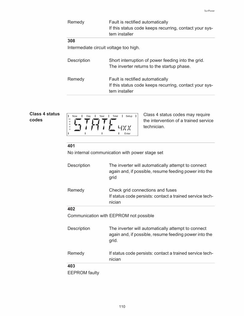
110
SunPower
Class 4 status
codesClass 4 status codes may require
the intervention of a trained service
technician.
Remedy Fault is rectified automatically!
If this status code keeps recurring, contact your sys-
tem installer
308
Intermediate circuit voltage too high.!
Description Short interruption of power feeding into the grid.!
The inverter returns to the startup phase.!
Remedy Fault is rectified automatically!
If this status code keeps recurring, contact your sys-
tem installer
401
No internal communication with power stage set !
Description The inverter will automatically attempt to connect
again and, if possible, resume feeding power into the
grid!
Remedy Check grid connections and fuses!
If status code persists: contact a trained service tech-
nician
402
Communication with EEPROM not possible!
Description The inverter will automatically attempt to connect
again and, if possible, resume feeding power into the
grid. !
Remedy If status code persists: contact a trained service tech-
nician
403
EEPROM faulty!

111
SunPower
Description The inverter will automatically attempt to connect
again and, if possible, resume feeding power into the
grid. !
Remedy If status code persists: contact a trained service tech-
nician
406
One or both temperature sensors are defective!
Description The inverter disconnects from the grid for safety rea-
sons. !
Remedy If status code persists: contact a trained service tech-
nician
407
Temperature sensor at cooling element defective!
Description The inverter disconnects from the grid for safety rea-
sons. !
Remedy If status code persists: contact a trained service tech-
nician
408
Direct current feed in!
Description The inverter disconnects from the grid for safety rea-
sons. !
Remedy If status code persists: contact a trained service tech-
nician
412
The "fixed voltage" setting has been selected instead of MPP voltage op-
eration and the voltage is set to a value that is too low, or the DC voltage
exceeds allowable limits. !
Description Fixed voltage lower than the current MPP voltage. !
Remedy Remove excess solar modules so DC voltage fits
within inverter limits !
If the status code persists: contact a trained service
technician

112
SunPower
413
Control problems!
Description The inverter briefly disconnects from the grid, if AC
voltage or frequency are out of range. !
Remedy If status code persists: contact a trained service tech-
nician
414
EEPROM faulty!
Description Memory deleted!
Remedy If status code persists: contact a trained service tech-
nician
416
Communication with IG Brain not possible. !
Description The Operating Status LED lights up orange, then the
inverter attempts a restart. !
Remedy If status code persists: contact a trained service tech-
nician
417
Two power stage sets have the same PC board number!
Description The inverter stops feeding power into the grid, the
display shows a critical error via a red Operating Sta-
tus LED!
Remedy If status code persists: contact a trained service tech-
nician
419
Two or more power stage sets with an identical software serial number de-
tected. !
Description The inverter stops feeding power into the grid, the
display shows a critical error via a red Operating Sta-
tus LED!
Remedy If status code persists: contact a trained service tech-
nician

113
SunPower
421
PC board number has been set incorrectly!
Description The inverter stops feeding power into the grid, the
display shows a critical error via a red Operating Sta-
tus LED. !
Remedy If status code persists: contact a trained service tech-
nician
425
Communication with the power stage set is not possible!
Description The Operating Status LED lights up orange, then the
inverter attempts a restart. !
Remedy If status code persists: contact a trained service tech-
nician
431
All power stage sets are in boot mode. !
Description The inverter stops feeding power into the grid, the
display shows a critical error via a red Operating Sta-
tus LED. !
Remedy Update firmware using Bootloader
Switches between SLAVE / DC LOW or SLAVE / POWER LOW (439)
The MPP master power stage set is switched off because of an error in a
slave power stage set (in the balance mode). !
Description The inverter stops feeding power into the grid, the
display shows a critical error via a red Operating Sta-
tus LED. !
Remedy If status code persists: contact a trained service tech-
nician
442
No phase master for a phase!
Description The inverter stops feeding power into the grid, the
display shows a critical error via a red Operating Sta-
tus LED. !

114
SunPower
Remedy If status code persists: contact a trained service tech-
nician
443
Energy transfer not possible!
Description The inverter stops feeding power into the grid, the
display shows a critical error via a red Operating Sta-
tus LED. !
Remedy If status code persists: contact a trained service tech-
nician
445
Invalid power stage set configuration!
Description The inverter stops feeding power into the grid, the
display shows a critical error via a red Operating Sta-
tus LED. !
Remedy If status code persists: contact a trained service tech-
nician
446
Internal communication error with the NL-MON plug-in card!
Description The inverter will automatically attempt to connect
again and, if possible, resume feeding power into the
grid!
Remedy Check grid connections and fuses;!
If status code persists: contact a trained service tech-
nician
447
The NL-MON plug-in card has interrupted grid monitoring!
Description The inverter will automatically attempt to connect
again and, if possible, resume feeding power into the
grid!
Remedy If status code persists: contact a trained service tech-
nician
448
The neutral conductor N is not connected!

115
SunPower
Description The inverter disconnects from the grid for safety rea-
sons. !
Remedy If status code persists: contact a trained service tech-
nician
450
The monitoring of the power stage set main processor ‘Guard’ is active!
Description The inverter stops feeding power into the grid, the
display shows a critical error via a red Operating Sta-
tus LED. !
Remedy If status code persists: contact a trained service tech-
nician
451
The EEPROM Guard Control is defective!
Description The inverter stops feeding power into the grid, the
display shows a critical error via a red Operating Sta-
tus LED. !
Remedy If status code persists: contact a trained service tech-
nician
452
Communication between ‘Guard’ and the digital signal processor (DSP)
has been interrupted!
Description The inverter stops feeding power into the grid, the
display shows a critical error via a red Operating Sta-
tus LED. !
Remedy If status code persists: contact a trained service tech-
nician
453
Error in grid voltage recording!
Description The inverter stops feeding power into the grid, the
display shows a critical error via a red Operating Sta-
tus LED. !
Remedy If status code persists: contact a trained service tech-
nician

116
SunPower
454
Error in grid frequency recording!
Description The inverter stops feeding power into the grid, the
display shows a critical error via a red Operating Sta-
tus LED. !
Remedy If status code persists: contact a trained service tech-
nician
455
Reference power source for AC measurement is operating outside of tol-
erances!
Description The inverter stops feeding power into the grid, the
display shows a critical error via a red Operating Sta-
tus LED. !
Remedy If status code persists: contact a trained service tech-
nician
456
Error during anti-islanding test!
Description The inverter stops feeding power into the grid, the
display shows a critical error via a red Operating Sta-
tus LED. !
Remedy If status code persists: contact a trained service tech-
nician
457
Grid relay stuck!
Description The inverter stops feeding power into the grid, the
display shows a critical error via a red Operating Sta-
tus LED. !
Remedy If status code persists: contact a trained service tech-
nician
460
Reference power source for the digital signal processor (DSP) is operating
outside of tolerances!
117
SunPower
Description The inverter stops feeding power into the grid, the
display shows a critical error via a red Operating Sta-
tus LED. !
Remedy If status code persists: contact a trained service tech-
nician
461
Error in DSP data memory!
Description The inverter stops feeding power into the grid, the
display shows a critical error via a red Operating Sta-
tus LED. !
Remedy If status code persists: contact a trained service tech-
nician
464
Display error !
The software and/or hardware versions of the display and IG Brain are not
compatible. !
Description The inverter stops feeding power into the grid, the
display shows a critical error via a red Operating Sta-
tus LED. !
Remedy Update firmware using Bootloader
465
Display error !
The UI command sent from the IG Brain is not recognized by the present
display version. !
Description The inverter stops feeding power into the grid, the
display shows a critical error via a red Operating Sta-
tus LED. !
Remedy If status code persists: contact a trained service tech-
nician
466
Display error !
The display was not detected. !
Description The inverter stops feeding power into the grid, the
display shows a critical error via a red Operating Sta-
tus LED. !

118
SunPower
Remedy Check the display for damage, connect display,
check ribbon wire for damage, check IG Brain for
damage !
If status code persists: contact a trained service tech-
nician
467
The display has not received a start command from the IG Brain for longer
than 6 s. !
Description The inverter will automatically attempt to connect
again and, if possible, resume feeding power into the
grid. !
Remedy If status code persists: contact a trained service tech-
nician
469
Output choke connected to wrong poles!
Description The inverter stops feeding power into the grid, the
display shows a critical error via a red Operating Sta-
tus LED. !
Remedy Properly connect output choke !
If status code persists: contact a trained service tech-
nician
470
The buck converter relay does not open at high DC voltage !
Description The inverter stops feeding power into the grid, the
display shows a critical error via a red Operating Sta-
tus LED. !
Remedy Check system configuration !
If status code persists: contact a trained service tech-
nician
472
Ground fault detected !
Description Inverter is blocked from feeding energy into the grid. !
Remedy Replace GFDI fuse.
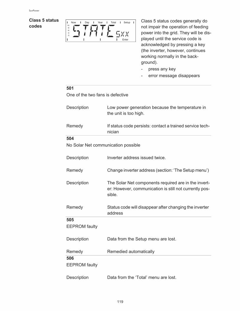
119
SunPower
Class 5 status
codesClass 5 status codes generally do
not impair the operation of feeding
power into the grid. They will be dis-
played until the service code is
acknowledged by pressing a key
(the inverter, however, continues
working normally in the back-
ground).
- press any key
- error message disappears
501
One of the two fans is defective!
Description Low power generation because the temperature in
the unit is too high. !
Remedy If status code persists: contact a trained service tech-
nician
504
No Solar Net communication possible!
Description Inverter address issued twice. !
Remedy Change inverter address (section: ‘The Setup menu’) !
Description The Solar Net components required are in the invert-
er: However, communication is still not currently pos-
sible. !
Remedy Status code will disappear after changing the inverter
address
505
EEPROM faulty!
Description Data from the Setup menu are lost. !
Remedy Remedied automatically
506
EEPROM faulty!
Description Data from the ‘Total’ menu are lost. !
120
SunPower
Remedy Remedied automatically
507
EEPROM faulty!
Description Data from the ‘Day’ / ‘Year’ menu are lost. !
Remedy Remedied automatically
508
Inverter address incorrect!
Description Address for data communication is no longer saved. !
Remedy Set address again
509
24h no feed in!
Description Example: solar modules covered with snow!
Remedy Example: remove snow from solar modules
510
EEPROM faulty!
Description SMS settings were restored to default. !
Remedy If necessary, reconfigure SMS
511
EEPROM faulty!
Description Sensor card settings were restored to default!
Remedy If necessary, reconfigure metering channels
512
Too many power stage sets in the system!
Description Too many power stage sets have been detected in
the system. !
Remedy If status code persists: contact a trained service tech-
nician
513
Power stage set in boot mode!

121
SunPower
Description One or more power stage sets cannot be activated
because they are in boot mode. !
Remedy Update power stage set firmware
514
No communication with one of the power stage sets!
Description Warning message from one of the power stage sets,
second power stage set working normally!
Remedy If status code persists: contact a trained service tech-
nician
515
Faulty plug connections!
Description Temperature sensor on cooling element faulty or not
connected properly. !
Remedy If status code persists: contact a trained service tech-
nician
516
Status codes present for one of the power stage sets !
Description It is not possible to activate all power stage sets!
Remedy Carry out analysis. For more information, see the
‘The setup menu’ section. If status code persists:
contact a trained service technician
517
Change of master has taken place !
Description Transformer not connected / not plugged in !
Bridge short-circuit !
Detection of intermediate circuit voltage damaged !
Remedy Check possible errors referred to in ‘Description.’ If
status code persists: contact a trained service techni-
cian
550
String fuse defective. !
Description One or more string fuses are defective. !
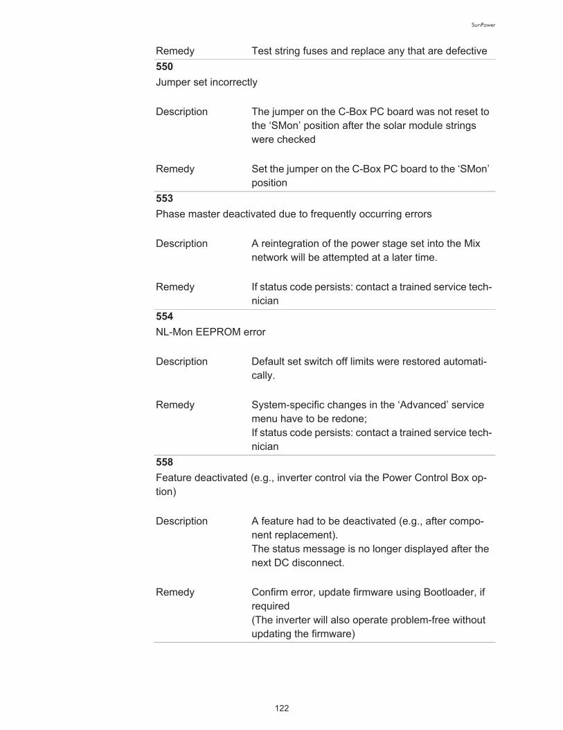
122
SunPower
Remedy Test string fuses and replace any that are defective
550
Jumper set incorrectly!
Description The jumper on the C-Box PC board was not reset to
the ‘SMon’ position after the solar module strings
were checked!
Remedy Set the jumper on the C-Box PC board to the ‘SMon’
position
553
Phase master deactivated due to frequently occurring errors!
Description A reintegration of the power stage set into the Mix
network will be attempted at a later time. !
Remedy If status code persists: contact a trained service tech-
nician
554
NL-Mon EEPROM error!
Description Default set switch off limits were restored automati-
cally. !
Remedy System-specific changes in the ‘Advanced’ service
menu have to be redone; !
If status code persists: contact a trained service tech-
nician
558
Feature deactivated (e.g., inverter control via the Power Control Box op-
tion) !
Description A feature had to be deactivated (e.g., after compo-
nent replacement). !
The status message is no longer displayed after the
next DC disconnect. !
Remedy Confirm error, update firmware using Bootloader, if
required !
(The inverter will also operate problem-free without
updating the firmware)
123
SunPower
Customer Ser-
viceIMPORTANT! Please contact your SunPower dealer or a trained service
partner if
- an error appears frequently or for a long period of time
- an error appears that is not listed in the tables

124
SunPower
Maintenance
Safety
General The inverter is designed so that it does not require additional maintenance.
However, there are a few points to keep in mind during operation to ensure
that the inverter functions optimally.
WARNING! An electric shock can be fatal. Danger from grid voltage
and DC voltage from solar modules.
- The connection area should only be opened by a licensed elec-
trician.
- The separate power stage set area should only be disconnected
from the connection area after first being disconnected from the
grid power.
- The separate power stage set area should only be opened by
trained service personnel.
Never work with live wires! Prior to all connection work, make sure
that the AC and DC wires are not charged.
The DC main switch is used only to switch off power to the power
stage set. When the DC main switch is turned off, the connection
area is still energized.
These servicing instructions are for use by qualified personnel only.
To reduce the risk of electric shock, do not perform any servicing
other than that specified in the operating instructions.
WARNING! An electric shock can be fatal. Danger from residual
voltage from capacitors.
You must wait until the capacitors have discharged. Discharge
takes 5 minutes.

125
SunPower
Operation in
Dusty Environ-
ments
When operating the inverter in ex-
tremely dusty environments:!
Remove the fan cover and clean the
integrated fly screen as required
Opening the
SunPower
SPR-f for ser-
vice/mainte-
nance
Procedure for opening the inverter for service or maintenance:
Disconnect AC and DC supply from the inverter
Open the connection area
Turn off DC main switch
Allow the capacitors to discharge (5 minutes)
Remove metal covers
Remove the plastic dividers
Remove string fuses
Disconnect DC wires
Disconnect AC wires
2
1
3
1
2
3
4
5
6
7
8
9

126
SunPower
Replacing String Fuses
Safety
Preparation
WARNING! An electric shock can be fatal. Danger from grid voltage
and DC voltage from solar modules.
- The connection area should only be opened by a licensed elec-
trician.
- Never work with live wires! Prior to all connection work, make
sure that the AC and DC wires are not charged.
- The DC main switch is used only to switch off power to the pow-
er stage set. When the DC main switch is turned off, the connec-
tion area is still energized.
These servicing instructions are for use by qualified personnel only.
To reduce the risk of electric shock, do not perform any servicing
other than that specified in the operating instructions.
WARNING! An electric shock can be fatal. Danger from residual
voltage from capacitors.
You must wait until the capacitors have discharged. Discharge
takes 5 minutes.
NOTE! Disconnected AC and DC supply from the inverter.
off
on
1
2
OFF
AC
1
1
4
2
3
2

127
SunPower
Replacing
string fuses
Test the fuse holder at the terminal for continuity
1
3
2
4
3
Lift up plastic dividers in the area of
thestring fuses
1
4
WARNING! An electric shock can be fatal. Danger from DC voltage
from solar modules.
- Never remove a fuse while it is under load.
- Fuse covers are for installation purposes only. They offer no
protection against contact.
NOTE! Only use fuses for solar modules that meet the criteria for
the proper selection of string fuses.
Fuse data: Diameter 0.406 x 1.378 - 1.496 in. (10.3 x 35 - 38 mm),
600 V DC
1

128
SunPower
After replacing the fuse:
- Find out and correct the cause for the defective fuse
Finally...
4
2
3
1
DC+
2
3
Return plastic dividers to their
proper position.
IMPORTANT! Make sure that the
plastic dividers are underneath any
data communication wires that are
present.
1
1
4
1
2
3
2
3
2
4
1
3

129
SunPower
off
on
1
ON
AC
2
4

130
SunPower
Replacing GFDI fuse
Safety
Preparation
WARNING! An electric shock can be fatal. Danger from grid voltage
and DC voltage from solar modules.
- The connection area should only be opened by a licensed elec-
trician.
- Never work with live wires! Prior to all connection work, make
sure that the AC and DC wires are not charged.
- The DC main switch is used only to switch off power to the pow-
er stage set. When the DC main switch is turned off, the connec-
tion area is still energized.
These servicing instructions are for use by qualified personnel only.
To reduce the risk of electric shock, do not perform any servicing
other than that specified in the operating instructions.
WARNING! An electric shock can be fatal. Danger from residual
voltage from capacitors.
You must wait until the capacitors have discharged. Discharge
takes 5 minutes.
WARNING! An electric shock can be fatal. Normally grounded con-
ductors may be ungrounded and energized when a ground fault is
indicated. The ground fault has to be repaired before operation is re-
sumed.
NOTE! Disconnect AC and DC supply from the inverter.
off
on
1
2
OFF
AC
1
1
4
2
3
2

131
SunPower
If present, disconnect data communication wire from the option cards.
Replacing
GFDI fuse
Test the fuse holder at the terminal for continuity
After replacing the fuse:
- Find out and correct the cause for the defective fuse
1
3
2
4
3
4
WARNING! An electric shock can be fatal. Danger from DC voltage
from solar modules.
- Never remove a fuse while it is under load.
- Fuse covers are for installation purposes only. They offer no
protection against contact.
NOTE! Only use fuses that comply with the following data for the
GFDI fuse:
Diameter 0.406 x 1.378 - 1.496 in. (10.3 x 35 - 38 mm), 1 A, 600 V
DC
1
41
4
1
2
3
2
3

132
SunPower
Finally... Connect available data communication wire to the option cards.
IMPORTANT! Make sure that the plastic dividers are underneath any data
communication wires that are present.
1
4
1
2
3
2
3
2
4
1
3
off
on
1
ON
AC
2
4

SunPower
Appendix

134
SunPower
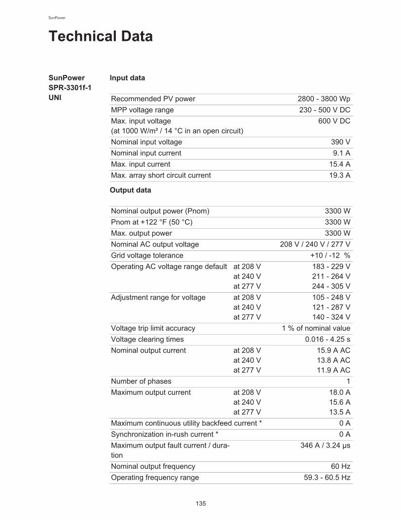
135
SunPower
Technical Data
SunPower !
SPR-3301f-1
UNI
Input data
Output data
Recommended PV power 2800 - 3800 Wp
MPP voltage range 230 - 500 V DC
Max. input voltage!
(at 1000 W/m² / 14 °C in an open circuit)
600 V DC
Nominal input voltage 390 V
Nominal input current 9.1 A
Max. input current 15.4 A
Max. array short circuit current 19.3 A
Nominal output power (Pnom) 3300 W
Pnom at +122 °F (50 °C) 3300 W
Max. output power 3300 W
Nominal AC output voltage 208 V / 240 V / 277 V
Grid voltage tolerance +10 / -12 %
Operating AC voltage range default at 208 V!
at 240 V!
at 277 V
183 - 229 V
211 - 264 V
244 - 305 V
Adjustment range for voltage at 208 V!
at 240 V!
at 277 V
105 - 248 V
121 - 287 V
140 - 324 V
Voltage trip limit accuracy 1 % of nominal value
Voltage clearing times 0.016 - 4.25 s
Nominal output current at 208 V!
at 240 V!
at 277 V
15.9 A AC
13.8 A AC
11.9 A AC
Number of phases 1
Maximum output current at 208 V!
at 240 V!
at 277 V
18.0 A
15.6 A
13.5 A
Maximum continuous utility backfeed current * 0 A
Synchronization in-rush current * 0 A
Maximum output fault current / dura-
tion
346 A / 3.24 µs
Nominal output frequency 60 Hz
Operating frequency range 59.3 - 60.5 Hz

136
SunPower
* assured by electrical design of the inverter
General data
Safety equipment
Adjustment range for frequency 57.0 - 60.48 Hz
Frequency trip limit accuracy 0.05 Hz
Frequency clearing times 0.016 - 300 s
Harmonic distortion < 3 %
Power factor cos phi 1
Maximum efficiency 96.2 %
CEC efficiency at 208 V!
at 240 V!
at 277 V
95.5 %
95.5 %
96.0 %
Night consumption < 1.5 W
Consumption during operation 8 W
Cooling Controlled forced ventila-
tion
Degree of protection NEMA 3R
Unit dimensions w x h x d 17.09 x 26.50 x 9.84 in.
434 x 673 x 250 mm
Power stage set weight 31 lbs.
14 kg
Connection area weight 24 lbs.
11 kg
Shipping dimensions w x h x d 20.28 x 31.10 x 14.37 in.
515 x 790 x 365 mm
Shipping weight 59 lbs.
27 kg
Permissible ambient temperature !
(with 95% rel. humidity)
-4 °F - +131 °F
- 20 °C - +55 °C
Zulässige Lagertemperatur !
(with 95% rel. humidity)
-4 °F - +149 °F
- 20 °C - +65 °C
Ground fault protection internal GFDI
(Ground Fault Detector/Interrupter)
Islanding protection integrated
Protection against reverse polarity integrated
Over temperature output power derating /
active cooling
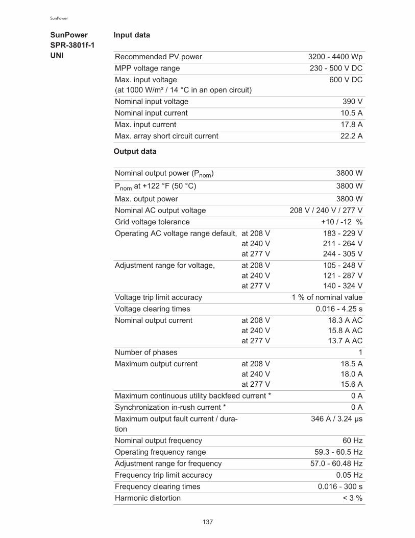
137
SunPower
SunPower !
SPR-3801f-1
UNI
Input data
Output data
Recommended PV power 3200 - 4400 Wp
MPP voltage range 230 - 500 V DC
Max. input voltage !
(at 1000 W/m² / 14 °C in an open circuit)
600 V DC
Nominal input voltage 390 V
Nominal input current 10.5 A
Max. input current 17.8 A
Max. array short circuit current 22.2 A
Nominal output power (Pnom) 3800 W
Pnom at +122 °F (50 °C) 3800 W
Max. output power 3800 W
Nominal AC output voltage 208 V / 240 V / 277 V
Grid voltage tolerance +10 / -12 %
Operating AC voltage range default, at 208 V !
at 240 V !
at 277 V
183 - 229 V
211 - 264 V
244 - 305 V
Adjustment range for voltage, at 208 V !
at 240 V !
at 277 V
105 - 248 V
121 - 287 V
140 - 324 V
Voltage trip limit accuracy 1 % of nominal value
Voltage clearing times 0.016 - 4.25 s
Nominal output current at 208 V !
at 240 V !
at 277 V
18.3 A AC
15.8 A AC
13.7 A AC
Number of phases 1
Maximum output current at 208 V !
at 240 V !
at 277 V
18.5 A
18.0 A
15.6 A
Maximum continuous utility backfeed current * 0 A
Synchronization in-rush current * 0 A
Maximum output fault current / dura-
tion
346 A / 3.24 µs
Nominal output frequency 60 Hz
Operating frequency range 59.3 - 60.5 Hz
Adjustment range for frequency 57.0 - 60.48 Hz
Frequency trip limit accuracy 0.05 Hz
Frequency clearing times 0.016 - 300 s
Harmonic distortion < 3 %

138
SunPower
* assured by electrical design of the inverter
General data
Safety equipment
Power factor cos phi 1
Maximum efficiency 96.2 %
CEC efficiency at 208 V !
at 240 V !
at 277 V
95.0 %
95.5 %
96.0 %
Night consumption < 1.5 W
Consumption during operation 8 W
Cooling Controlled forced ventila-
tion
Degree of protection NEMA 3R
Unit dimensions w x h x d 17.09 x 26.50 x 9.84 in.
434 x 673 x 250 mm
Power stage set weight 31 lbs.
14 kg
Connection area weight 24 lbs.
11 kg
Shipping dimensions w x h x d 20.28 x 31.10 x 14.37 in.
515 x 790 x 365 mm
Shipping weight 59 lbs.
27 kg
Permissible ambient temperature !
(with 95% rel. humidity)
-4 °F - +131 °F
- 20 °C - +55 °C
Permissible storage temperature !
(with 95% rel. humidity)
-4 °F - +149 °F
- 20 °C - +65 °C
Ground fault protection internal GFDI
(Ground Fault Detector/Interrupter)
Islanding protection integrated
Protection against reverse polarity integrated
Over temperature output power derating /
active cooling

139
SunPower
SunPower !
SPR-6501f-1
UNI
Input data
Output data
Recommended PV power 5500 - 7500 Wp
MPP voltage range 230 - 500 V DC
Max. input voltage !
(at 1000 W/m² / 14 °C in an open circuit)
600 V DC
Nominal input voltage 390 V
Nominal input current 17.9 A
Max. input current 30.4 A
Max. array short circuit current 38.0 A
Nominal output power (Pnom) 6500 W
Pnom at +122 °F (50 °C) 6500 W
Max. output power 6500 W
Nominal AC output voltage 208 V / 240 V / 277 V
Grid voltage tolerance +10 / -12 %
Operating AC voltage range default, at 208 V !
at 240 V !
at 277 V
183 - 229 V
211 - 264 V
244 - 305 V
Adjustment range for voltage, at 208 V !
at 240 V !
at 277 V
105 - 248 V
121 - 287 V
140 - 324 V
Voltage trip limit accuracy 1 % of nominal value
Voltage clearing times 0.016 - 4.25 s
Nominal output current at 208 V !
at 240 V !
at 277 V
31.3 A AC
27.1 A AC
23.5 A AC
Number of phases 1
Maximum output current at 208 V !
at 240 V !
at 277 V
35.5 A
30.8 A
26.6 A
Maximum continuous utility backfeed current * 0 A
Synchronization in-rush current * 0 A
Maximum output fault current / dura-
tion
462 A / 125 µs
Nominal output frequency 60 Hz
Operating frequency range 59.3 - 60.5 Hz
Adjustment range for frequency 57.0 - 60.48 Hz
Frequency trip limit accuracy 0.05 Hz
Frequency clearing times 0.016 - 300 s
Harmonic distortion < 3 %

140
SunPower
* assured by electrical design of the inverter
General data
Safety equipment
Power factor cos phi 1
Maximum efficiency 96.2 %
CEC efficiency at 208 V !
at 240 V !
at 277 V
95.0 %
95.5 %
96.0 %
Night consumption < 1.5 W
Consumption during operation 14 W
Cooling Controlled forced ventila-
tion
Degree of protection NEMA 3R
Unit dimensions w x h x d 17.09 x 38.11 x 9.84 in.
434 x 968 x 250 mm
Power stage set weight 57 lbs.
26 kg
Connection area weight 24 lbs.
11 kg
Shipping dimensions w x h x d 20.28 x 42.72 x 14.37 in.
515 x 1085 x 365 mm
Shipping weight 90 lbs.
41 kg
Permissible ambient temperature !
(with 95% rel. humidity)
-4 °F - +131 °F
- 20 °C - +55 °C
Permissible storage temperature !
(with 95% rel. humidity)
-4 °F - +149 °F
- 20 °C - +65 °C
Ground fault protection internal GFDI
(Ground Fault Detector/Interrupter)
Islanding protection integrated
Protection against reverse polarity integrated
Over temperature output power derating /
active cooling

141
SunPower
SunPower !
SPR-7501f-1
UNI
Input data
Output data
Recommended PV power 6350 - 8600 Wp
MPP voltage range 230 - 500 V DC
Max. input voltage !
(at 1000 W/m² / 14 °C in an open circuit)
600 V DC
Nominal input voltage 390 V
Nominal input current 20.7 A
Max. input current 35.1 A
Max. array short circuit current 43.8 A
Nominal output power (Pnom) 7500 W
Pnom at +122 °F (50 °C) 7500 W
Max. output power 7500 W
Nominal AC output voltage 208 V / 240 V / 277 V
Grid voltage tolerance +10 / -12 %
Operating AC voltage range default, at 208 V !
at 240 V !
at 277 V
183 - 229 V
211 - 264 V
244 - 305 V
Adjustment range for voltage, at 208 V !
at 240 V !
at 277 V
105 - 248 V
121 - 287 V
140 - 324 V
Voltage trip limit accuracy 1 % of nominal value
Voltage clearing times 0.016 - 4.25 s
Nominal output current at 208 V !
at 240 V !
at 277 V
36.1 A AC
31.3 A AC
27.1 A AC
Number of phases 1
Maximum output current at 208 V !
at 240 V !
at 277 V
37.0 A
35.5 A
30.7 A
Maximum continuous utility backfeed current * 0 A
Synchronization in-rush current * 0 A
Maximum output fault current / dura-
tion
462 A / 125 µs
Nominal output frequency 60 Hz
Operating frequency range 59.3 - 60.5 Hz
Adjustment range for frequency 57.0 - 60.48 Hz
Frequency trip limit accuracy 0.05 Hz
Frequency clearing times 0.016 - 300 s
Harmonic distortion < 3 %

142
SunPower
* assured by electrical design of the inverter
General data
Safety equipment
Power factor cos phi 1
Maximum efficiency 96.2 %
CEC efficiency at 208 V !
at 240 V !
at 277 V
95.0 %
95.5 %
96.0 %
Night consumption < 1.5 W
Consumption during operation 14 W
Cooling Controlled forced ventila-
tion
Degree of protection NEMA 3R
Unit dimensions w x h x d 17.09 x 38.11 x 9.84 in.
434 x 968 x 250 mm
Power stage set weight 57 lbs.
26 kg
Connection area weight 24 lbs.
11 kg
Shipping dimensions w x h x d 20.28 x 42.72 x 14.37 in.
515 x 1085 x 365 mm
Shipping weight 90 lbs.
41 kg
Permissible ambient temperature !
(with 95% rel. humidity)
-4 °F - +131 °F
- 20 °C - +55 °C
Permissible storage temperature !
(with 95% rel. humidity)
-4 °F - +149 °F
- 20 °C - +65 °C
Ground fault protection internal GFDI
(Ground Fault Detector/Interrupter)
Islanding protection integrated
Protection against reverse polarity integrated
Over temperature output power derating /
active cooling
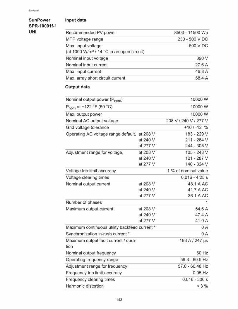
143
SunPower
SunPower !
SPR-10001f-1
UNI
Input data
Output data
Recommended PV power 8500 - 11500 Wp
MPP voltage range 230 - 500 V DC
Max. input voltage !
(at 1000 W/m² / 14 °C in an open circuit)
600 V DC
Nominal input voltage 390 V
Nominal input current 27.6 A
Max. input current 46.8 A
Max. array short circuit current 58.4 A
Nominal output power (Pnom) 10000 W
Pnom at +122 °F (50 °C) 10000 W
Max. output power 10000 W
Nominal AC output voltage 208 V / 240 V / 277 V
Grid voltage tolerance +10 / -12 %
Operating AC voltage range default, at 208 V !
at 240 V !
at 277 V
183 - 229 V
211 - 264 V
244 - 305 V
Adjustment range for voltage, at 208 V !
at 240 V !
at 277 V
105 - 248 V
121 - 287 V
140 - 324 V
Voltage trip limit accuracy 1 % of nominal value
Voltage clearing times 0.016 - 4.25 s
Nominal output current at 208 V !
at 240 V !
at 277 V
48.1 A AC
41.7 A AC
36.1 A AC
Number of phases 1
Maximum output current at 208 V !
at 240 V !
at 277 V
54.6 A
47.4 A
41.0 A
Maximum continuous utility backfeed current * 0 A
Synchronization in-rush current * 0 A
Maximum output fault current / dura-
tion
193 A / 247 µs
Nominal output frequency 60 Hz
Operating frequency range 59.3 - 60.5 Hz
Adjustment range for frequency 57.0 - 60.48 Hz
Frequency trip limit accuracy 0.05 Hz
Frequency clearing times 0.016 - 300 s
Harmonic distortion < 3 %

144
SunPower
* assured by electrical design of the inverter
General data
Safety equipment
Power factor cos phi 1
Maximum efficiency 96.2 %
CEC efficiency at 208 V !
at 240 V !
at 277 V
95.0 %
95.5 %
96.0 %
Night consumption < 1.5 W
Consumption during operation 20 W
Cooling Controlled forced ventila-
tion
Degree of protection NEMA 3R
Unit dimensions w x h x d 17.09 x 49.72 x 9.84 in.
434 x 1263 x 250 mm
Power stage set weight 84 lbs.
38 kg
Connection area weight 26 lbs.
12 kg
Shipping dimensions w x h x d 20.28 x 42.72 x 14.37 in.
515 x 1085 x 365 mm
+
20.28 x 16.14 x 14.37 in.
515 x 410 x 365 mm
Shipping weight 114 lbs.
25 kg
Permissible ambient temperature !
(with 95% rel. humidity)
-4 °F - +131 °F
- 20 °C - +55 °C
Permissible storage temperature !
(with 95% rel. humidity)
-4 °F - +149 °F
- 20 °C - +65 °C
Ground fault protection internal GFDI
(Ground Fault Detector/Interrupter)
Islanding protection integrated
Protection against reverse polarity integrated
Over temperature output power derating /
active cooling

145
SunPower
SunPower !
SPR-11401f-1
UNI
Input data
Output data
Recommended PV power 9700 - 13100 Wp
MPP voltage range 230 - 500 V DC
Max. input voltage !
(at 1000 W/m² / 14 °C in an open circuit)
600 V DC
Nominal input voltage 390 V
Nominal input current 31.4 A
Max. input current 53.3 A
Max. array short circuit current 66.6 A
Nominal output power (Pnom) 11400 W
Pnom at +122 °F (50 °C) 11400 W
Max. output power 11400 W
Nominal AC output voltage 208 V / 240 V / 277 V
Grid voltage tolerance +10 / -12 %
Operating AC voltage range default, at 208 V !
at 240 V !
at 277 V
183 - 229 V
211 - 264 V
244 - 305 V
Adjustment range for voltage, at 208 V !
at 240 V !
at 277 V
105 - 248 V
121 - 287 V
140 - 324 V
Voltage trip limit accuracy 1 % of nominal value
Voltage clearing times 0.016 - 4.25 s
Nominal output current at 208 V !
at 240 V !
at 277 V
54.8 A AC
47.5 A AC
41.2 A AC
Number of phases 1
Maximum output current at 208 V !
at 240 V !
at 277 V
55.5 A
54.0 A
46.7 A
Maximum continuous utility backfeed current * 0 A
Synchronization in-rush current * 0 A
Maximum output fault current / dura-
tion
193 A / 247 µs
Nominal output frequency 60 Hz
Operating frequency range 59.3 - 60.5 Hz
Adjustment range for frequency 57.0 - 60.48 Hz
Frequency trip limit accuracy 0.05 Hz
Frequency clearing times 0.016 - 300 s
Harmonic distortion < 3 %

146
SunPower
* assured by electrical design of the inverter
General data
Safety equipment
Power factor cos phi 1
Maximum efficiency 96.2 %
CEC efficiency at 208 V !
at 240 V !
at 277 V
95.0 %
95.5 %
96.0 %
Night consumption < 1.5 W
Consumption during operation 20 W
Cooling Controlled forced ventila-
tion
Degree of protection NEMA 3R
Unit dimensions w x h x d 17.09 x 49.72 x 9.84 in.
434 x 1263 x 250 mm
Power stage set weight 84 lbs.
38 kg
Connection area weight 26 lbs.
12 kg
Shipping dimensions w x h x d 20.28 x 42.72 x 14.37 in.
515 x 1085 x 365 mm
+
20.28 x 16.14 x 14.37 in.
515 x 410 x 365 mm
Shipping weight 114 lbs.
25 kg
Permissible ambient temperature !
(with 95% rel. humidity)
-4 °F - +131 °F
- 20 °C - +55 °C
Permissible storage temperature !
(with 95% rel. humidity)
-4 °F - +149 °F
- 20 °C - +65 °C
Ground fault protection internal GFDI
(Ground Fault Detector/Interrupter)
Islanding protection integrated
Protection against reverse polarity integrated
Over temperature output power derating /
active cooling

147
SunPower
SunPower !
SPR-11401f-3-
208/240 Delta
Input data
Output data
* assured by electrical design of the inverter
Recommended PV power 9700 - 13100 Wp
MPP voltage range 230 - 500 V DC
Max. input voltage !
(at 1000 W/m² / 14 °C in an open circuit)
600 V DC
Nominal input voltage 390 V
Nominal input current 31.4 A
Max. input current 53.3 A
Max. array short circuit current 66.6 A
Nominal output power (Pnom) 11400 W
Pnom at +122 °F (50 °C) 11400 W
Max. output power 11400 W
Nominal AC output voltage 208 V / 240 V
Grid voltage tolerance +10 / -12 %
Operating AC voltage range default, at 208 V !
at 240 V
183 - 229 V
211 - 264 V
Adjustment range for voltage, at 208 V !
at 240 V
105 - 248 V
121 - 287 V
Voltage trip limit accuracy 1 % of nominal value
Voltage clearing times 0.016 - 4.25 s
Nominal output current at 208 V !
at 240 V
31.6 A AC
27.4 A AC
Number of phases 3
Maximum output current at 208 V !
at 240 V
32.0 A
31.2 A
Maximum continuous utility backfeed current * 0 A
Synchronization in-rush current * 0 A
Maximum output fault current / dura-
tion
324 A / 1.16 ms
Nominal output frequency 60 Hz
Operating frequency range 59.3 - 60.5 Hz
Adjustment range for frequency 57.0 - 60.48 Hz
Frequency trip limit accuracy 0.05 Hz
Frequency clearing times 0.016 - 300 s
Harmonic distortion < 3 %
Power factor cos phi 1

148
SunPower
General data
Safety equipment
Maximum efficiency 96.2 %
CEC efficiency at 208 V !
at 240 V
95.0 %
96.0 %
Night consumption < 1.5 W
Consumption during operation 20 W
Cooling Controlled forced ventila-
tion
Degree of protection NEMA 3R
Unit dimensions w x h x d 17.09 x 49.72 x 9.84 in.
434 x 1263 x 250 mm
Power stage set weight 84 lbs.
38 kg
Connection area weight 26 lbs.
12 kg
Shipping dimensions w x h x d 20.28 x 42.72 x 14.37 in.
515 x 1085 x 365 mm
+
20.28 x 16.14 x 14.37 in.
515 x 410 x 365 mm
Shipping weight 114 lbs.
25 kg
Permissible ambient temperature !
(with 95% rel. humidity)
-4 °F - +131 °F
- 20 °C - +55 °C
Permissible storage temperature !
(with 95% rel. humidity)
-4 °F - +149 °F
- 20 °C - +65 °C
Ground fault protection internal GFDI
(Ground Fault Detector/Interrupter)
Islanding protection integrated
Protection against reverse polarity integrated
Over temperature output power derating /
active cooling

149
SunPower
SunPower !
SPR-12001f-3-
277 WYE
Input data
Output data
* assured by electrical design of the inverter
Recommended PV power 10200 - 13800 Wp
MPP voltage range 230 - 500 V DC
Max. input voltage !
(at 1000 W/m² / 14 °C in an open circuit)
600 V DC
Nominal input voltage 390 V
Nominal input current 33.1 A
Max. input current 56.1 A
Max. array short circuit current 70.1 A
Nominal output power (Pnom) 12000 W
Pnom at +122 °F (50 °C) 12000 W
Max. output power 12000 W
Nominal AC output voltage 277 V
Grid voltage tolerance +10 / -12 %
Operating AC voltage range default, at 277 V 244 - 305 V
Adjustment range for voltage, at 277 V 140 - 324 V
Voltage trip limit accuracy 1 % of nominal value
Voltage clearing times 0.016 - 4.25 s
Nominal output current at 277 V 14.4 A AC
Number of phases 3
Maximum output current at 277 V 16.4 A
Maximum continuous utility backfeed current * 0 A
Synchronization in-rush current * 0 A
Maximum output fault current / dura-
tion
504 A / 3.26 ms
Nominal output frequency 60 Hz
Operating frequency range 59.3 - 60.5 Hz
Adjustment range for frequency 57.0 - 60.48 Hz
Frequency trip limit accuracy 0.05 Hz
Frequency clearing times 0.016 - 300 s
Harmonic distortion < 3 %
Power factor 1

150
SunPower
General data
Safety equipment
Maximum efficiency 96.2 %
CEC efficiency at 277 V 96.0 %
Night consumption < 1.5 W
Consumption during operation 20 W
Cooling Controlled forced ventila-
tion
Degree of protection NEMA 3R
Unit dimensions w x h x d 17.09 x 49.72 x 9.84 in.
434 x 1263 x 250 mm
Power stage set weight 84 lbs.
38 kg
Connection area weight 26 lbs.
12 kg
Shipping dimensions w x h x d 20.28 x 42.72 x 14.37 in.
515 x 1085 x 365 mm
+
20.28 x 16.14 x 14.37 in.
515 x 410 x 365 mm
Shipping weight 114 lbs.
25 kg
Permissible ambient temperature !
(with 95% rel. humidity)
-4 °F - +131 °F
- 20 °C - +55 °C
Permissible storage temperature !
(with 95% rel. humidity)
-4 °F - +149 °F
- 20 °C - +65 °C
Ground fault protection internal GFDI
(Ground Fault Detector/Interrupter)
Islanding protection integrated
Protection against reverse polarity integrated
Over temperature output power derating /
active cooling

151
SunPower
Field adjust-
able trip points
(1) 16.66 ms are equivalent to 1 cycle
(2) 25 ms are equivalent to 1.5 cycles
Field adjustable trip points 208 V 240 V 277 V
Nominal AC output voltage,!
Line-to-Line, [V]
208 240 277
Operating AC voltage range
default,!
Line-to-Line, [V]
183-229 211-264 -
Adjustment range for voltage,!
Line-to-Line, [V]
105-248 121-287 -
Voltage trip limit accuracy!
Line-to-Line,!
[% of nominal value]
1 1 -
Operating AC voltage range
default,!
Line-to-Neutral, [V]
106-132 106-132 244-305
Adjustment range for voltage,!
Line-to-Neutral, [V]
61-143 61-143 138-324
Adjustment range for voltage!
clearing time [s]
0.016-
4.25
0.016-
4.25
0.016-
4.25
Voltage trip limit accuracy!
Line-to-Neutral,!
[% of nominal value]
1 1 1
Nominal output frequency [Hz] 60 60 60
Operating frequency range
[Hz]
59.3-60.5 59.3-60.5 59.3-60.5
Adjustment range for frequen-
cy [Hz]
57.0-
60.48
57.0-
60.48
57.0-
60.48
Adjustment range for frequen-
cy!
clearing time [s]
0.016-300 0.016-300 0.016-300
Frequency trip limit accuracy!
[ms]16.66 (1) 16.66 (1) 16.66 (1)
Detection time [ms] 25 (2) 25 (2) 25 (2)
Reconnect time default [s] 300 300 300
Adjustment range for recon-
nect time [s]
5-900 5-900 5-900

152
SunPower
Relevant Standards and Directives
Relevant stan-
dards and di-
rectives
Grid Failure The standard measurement and safety procedures integrated into the in-
verter ensure that the power feed is immediately interrupted in the event of
a grid failure (shut-off by the utility or damage to lines).
- UL 1741-2005
- IEEE 1547-2003
- IEEE 1547.1
- ANSI/IEEE C62.41
- FCC Part 15 A & B
- NEC Article 690
- C22. 2 No. 107.1-01!
(September 2001)

153
SunPower
The 'C' and 'US' indicators adjacent to the CSA Mark signify that the product has been evaluated to the applicable CSA and ANSI/UL Standards, for use in Canada and
the U.S., respectively. This 'US' indicator includes products eligible to bear the 'NRTL' indicator. NRTL, i.e. National Recognized Testing Laboratory, is a designation
granted by the U.S. Occupational Safety and Health Administration (OSHA) to laboratories which have been recognized to perform certification to U.S. Standards. FF01
DQD 507 Rev. 2004-06-30
Certificate of Compliance Certificate: 2107866 Master Contract: 245329
Project: 2107866 Date Issued: November 28, 2008
Issued to: SunPower Corporation
3939 North First Street
San Jose, CA 95134
USA
Attention: Ms. Connie Kwan
The products listed below are eligible to bear the CSA Mark shown
with adjacent indicator 'US'
Issued by: Jocelyn Jens
Technical Assistant
Authorized by: Terry Nagy
Operations Manager
PRODUCTS
CLASS 5311 89 - POWER SUPPLIES - Distributed Generation - Power Systems Equipment (Certified to U.S.
Standards)
Utility Interactive Inverter, Models SunPower SPR-3300f, SunPower SPR-4000f, SunPower SPR-6500f,
SunPower SPR-8000f, SunPower SPR-12000f, permanently connected, system ratings as follows:

SunPower Corporation3939N. First Street
San Jose, California 95134, USATel 1-877-SUN-0123Fax 408.877.1808DMS # 001-67202 Rev.**
Tel 1-800-SUNPOWER (1-800-786-7693)