spray ctg sh 07 eu engineering handbook - pnr france€¦ · spray nozzle types 11 ... we hope the...
TRANSCRIPT

SPRAY ENGINEERING
HANDBOOK
CTG SH 07 EU
TECHNICAL PUBLICATIONSPNR manufactures a complete range of spray nozzles for industrial applications and many other products and systems designed according to the latest cutting-edge technologies All our products are described in the following catalogues
PRODUCT RANGE CTG TV GENERAL PURPOSE SPRAY NOZZLES CTG UGAIR ASSISTED ATOMIZERS CTG AZCOMPLEMENTARY PRODUCTS AND ASSEMBLY FITTINGS CTG ACINDUSTRIAL TANK WASHING SYSTEMS CTG LSPAPER MILL PRODUCTS CTG PMEVAPORATIVE COOLING LANCES CTG LNSTEELWORK NOZZLES CTG SWSPRAYDRY NOZZLES CTG SDFIREFIGHTING PRODUCTS AND SISTEMS CTG FF
Our technical literature is continuously revised and updated and sent to our Customers who are listed in our Catalogues Delivery List If you are interested in receiving the latest version of our catalogues please contact the nearest PNR officeWAIVER OF RESPONSABILITYThe information contained herein is provided ldquoas isrdquo and PNR does not guarantee the correctness and accuracy of the sameThis publication may contain technical inaccuracies or typographical errors It may also be subject to periodic changes without prior notice
INDEXGENERAL INFORMATION
International system of units 4Prefix tables for SI units 5Conversion table American units to SI units 5Conversion tables temperature scales 6Metric and decimal equivalents of fractions of an inch 7
LIQUID SPRAY AND SPRAY NOZZLESLiquid spray 9Spray nozzle types 11Spray nozzle coding 13Computerized fluid dynamics 14Spray generation 15Droplet spectrum 16Nozzle flow rate 19Spray angle 21Spray distribution 23Influence of liquid viscosity 27Influence of liquid specific gravity 29Jet impact 30Pressure drop through a nozzle 32
NOZZLE MATERIALSPnr material codes 34Properties of materials 35Mechanical properties of materials 39Chemical resistance of materials 40
PIPINGPipes data 74Economic pipe sizes 75Pressure drop in clean steel pipes 76Flange dimensions 78Sieve size conversion chart 80
PNR PRODUCT RANGE
INDE
X
wwwpnr-nozzlescom CTG SH 07 EU
3wwwpnr-nozzlescomCTG SH 07 EU 3
Foreword
Along many years PNR engineers have been involved with Customers to find out the appropriate solution to specific application problems in numberless different industriesThis continuous cooperation has allowed us to gather a large quantity of information regarding practical spray nozzles applications which we make available every day to our CustomersWe like to thank alI our Customers for their past cooperation and for the invaluable help they have given us in designing and manufacturing an always more complete and efficient range of spray nozzles and spraying systemsTo make this information readily available and improve our service we have now decided to gather and organize it within a manualWe hope the reader will appreciate our work and welcome any suggestion or addition which may lead to improve and complete this manual
GENERAL INFORMATIONInternational system of units 4Prefix tables for SI units 5Conversion table American units to SI units 5Conversion tables temperature scales 6Metric and decimal equivalents of fractions of an inch 7
GENERAL INFORMATION
INTR
ODUC
TION
GENE
RAL
INFO
RMAT
ION
3
4 wwwpnr-nozzlescom CTG SH 07 EU
Description
The INTERNATIONAL SYSTEM OF UNITS sometimes called SI has been defined by the International Standards Organization (ISO) and is based upon metric units The following notes include most units which are likely to be used in handing of fluids The system consists of nine base units and supplementary units which are coherently derived from them The coherence con-sists in the fact that the product or the quotient of any two unit quantities in the system result in another unit quantity Because of the world wide trend to use this modern metric system we are providing in the following the conversion constants for the most useful units
Base Units and derived units
The SI has defined the following base unit
GENE
RAL
INFO
RMAT
ION
Ndeg QUANTITY UNIT NAME UNIT SYMBOL
1 Length meter m
2 Mass kilogram kg
3 Time second s
4 Thermodynamic temperature Kelvin K
5 Molecular substance mole mol
6 Electric current Ampere A
7 Light intensity candela cd
8 Plane angle radiante rad
9 Solid angle steradian sr
Out of these base units many other have been derived the most interesting for our purposes being listed below
Ndeg QUANTITY UNIT NAME UNIT SYMBOL EQUIVALENCES
10 Area square meter m2
11 Volume cubic meter m3
12 Density kilogram per cubic meter Kgm3
13 Velocity meter per second ms
14 Acceleration meter per second squared ms2
15 Angular velocity radian per second rad s
16 Frequency Hertz Hz Hz = cicli s
17 Force Newton N N = kg ms2
18 Pressure Pascal Pa Pa = Nm2
19 Momentum kilogram meter per second Kg ms
20 Energy Joule J J = N m
21 Power Watt W W = Js
22 Moment of force Newton meter N m
23 Kinematic viscosity square meter per second m2s
24 Dynamic Viscosity Pascal second Pa s
25 Thermal conductivity Watt per meter Kelvin W (m K)
GENERAL INFORMATION International system of units
5wwwpnr-nozzlescomCTG SH 07 EU
GENE
RAL
INFO
RMAT
ION
AMERICAN UNIT CONVERSION FACTOR SI UNITPound masscubic feet 16018 kilogramscubic meterGallons per minute 3785 liters per minute (lpm)US Gallon 3785 liter (I)Pound force 4448 Newton (N)BTU (British Thermal Unit) 1055 Joule (J)BTU per hour 02931 Watt (W)BTU per pounddeg F 4184 Joule (kg K)mil 254 Micrometer (micron)Inches 254 millimeters (mm)Foot 03048 meter (m)Horsepower 0746 kilowatt (kW)Pounds per square inch 00689 bar (1 bar = 100 kPa)BTU per pound 2326 Joule per kgLbs per gallon 01198 kg per liter (kgl)Square inch 64516 square centimeter (cm2)Square foot 00929 square meter (m2)Acre 04047 hectares (ha)Foot per second 03048 meters per second (msec)Foot per minute 03048 meters per minute (mmin)Miles per hours 1609 kilometers per hour (kmh)Knots 1852 kilometers per hour (kmh)Cubic foot 00283 cubic meter (m3)Cubic inch 16387 cubic centimeter (cm3)Pound 04536 kilogram (kg)Ton 090272 metric ton (t)
QUANTITYDENSITYFLOW RATEFLUID VOLUMEFORCEHEATHEAT TRANSFERSPECIFIC HEAT CAPACITYLENGHTLENGHTLENGHTPOWERPRESSURECALORIC VALUE ENTALPYSPECIFIC WEIGHTSURFACESURFACESURFACEVELOCITYVELOCITYVELOCITYVELOCITYVOLUMEVOLUMEWEIGHTWEIGHT
Multiply American Units on the left (by the conversion factor) to obtain SI Units on the right Divide SI Units on the right (by the conversion factor) to obtain American Units on the left
GENERAL INFORMATION Prefix tables for SI units
Prefixes
SI units can be indicated together with a prefix to easily indicate very large or very small numbersAs an example visible light has a wave length of approximately 00000005 m (meters) which can be more easily written as 500 nm (nanometers)Please note it is not allowed to use prefixes together you cannot write 10000 m = 1da-km
10n Prefix Symbol Denomination Decimal equivalent1024 yotta Y 1 000 000 000 000 000 000 000 0001021 zetta Z 1 000 000 000 000 000 000 0001018 exa E 1 000 000 000 000 000 0001015 peta P 1 000 000 000 000 0001012 tera T 1 000 000 000 000109 giga G 1 000 000 000106 mega M Million 1 000 000103 kilo k Thousand 1 000102 etto h Hundred 10010 deca da Ten 1010minus1 deci d Tenth 0110minus2 centi c Hundredth 00110minus3 milli m Thousandth 000110minus6 micro micro Millionth 0000 00110minus9 nano n 0000 000 00110minus12 pico p 0000 000 000 00110minus15 femto f 0000 000 000 000 00110minus18 atto a 0000 000 000 000 000 00110minus21 zepto z 0000 000 000 000 000 000 00110minus24 yocto y 0000 000 000 000 000 000 000 001
GENERAL INFORMATION Conversion table American units to Si units
NoteBecause of discrepancies between some denominations in English and American we only mention the commonly used deno-minations
6 wwwpnr-nozzlescom CTG SH 07 EU
There are 4 principal types of temperature scales used for indicate the temperature CENTIGRADE CELSIUS FAHRENHEIT KELVIN and RANKINE Kelvin and Celsius scales are used in Europe Rankine Fahrenheit are used in Anglo-Saxons countries
MP = water melting pointBP = water boiling point
GENE
RAL
INFO
RMAT
ION SYMBOL NAME MP BP NOTES
degC Centigrade 0 100 0 and 100 are arbitrarily placed at the freezing point andboiling point of water
degF Fahrenheit 32 212
0degF is the stabilized temperature when equal amounts ofice water and salt are mixed 96degF is the temperatureldquowhen the thermometer is held in the mouth or under thearmpit of a living man in good healthrdquo
degK Kelvin 27316 37316Based upon the definitions of the Centigrade scale and theexperimental evidence that absolute zero is ndash27316deg Cand that is an international standard temperature point
degR Rankine 49167 67167 Based upon the definitions of the Fahrenheit scale andthe experimental evidence that absolute zero is ndash27316deg C
degC degF43 1094
44 1112
45 113
46 1148
47 1166
48 1184
49 1202
50 122
51 1238
52 1256
53 1274
54 1292
55 131
56 1328
57 1346
58 1364
59 1382
60 140
61 1418
62 1436
63 1454
64 1472
65 149
66 1508
degC degF67 1526
68 1544
69 1562
70 158
71 1598
72 1616
73 1634
74 1652
75 167
76 1688
77 1706
78 1724
79 1742
80 176
81 1778
82 1796
83 1814
84 1832
85 185
86 1868
87 1886
88 1904
89 1922
90 194
degC degF91 1958
92 1976
93 1994
94 2012
95 203
96 2048
97 2066
98 2084
99 2102
100 212
105 221
110 230
115 239
120 248
125 257
130 266
135 275
140 284
145 293
150 302
160 320
170 338
180 356
190 374
degC degF19 662
20 68
21 698
22 716
23 734
24 752
25 77
26 788
27 806
28 824
29 842
30 86
31 878
32 896
33 914
34 932
35 95
36 968
37 986
38 1004
39 1022
40 104
41 1058
42 1076
degC degF-10 14
-8 176
-6 212
-4 248
-2 284
0 32
1 338
2 356
3 374
4 392
5 41
6 428
7 446
8 464
9 482
10 50
11 518
12 536
13 554
14 572
15 59
16 608
17 626
18 644
CONVERSION FORMULAE TABLE
CELSIUS FAHRENHEIT KELVIN RANKINE
degC= -
degF - 32 K - 27316
R - 27316
18 18
degF= 18 degC + 32 18K - 45969 R - 45969
K= degC + 27316
degF - 32 + 27316
- R
18 18
degR= 18 (degC + 27316) degF + 45967 18K -
GENERAL INFORMATION Conversion table temperature scales
7wwwpnr-nozzlescomCTG SH 07 EU
GENE
RAL
INFO
RMAT
ION
GENERAL INFORMATION Metric and decimal equivalents of fractions of an inch
5wwwpnr-nozzlescom
METRIC AND DECIMAL EQUIVALENTS OF FRACTIONS OF ONE INCH
mm FRACTIONS OF ONE INCH INCHES
03969 164 0015625079375 132 00312511906 364 00468715875 116 00625 19844 564 0078125238125 332 009375 27781 764 0109375 31750 18 012535719 964 014062396875 532 01562543656 1164 017187547625 316 1364 0187551594 0203125555625 732 02187559531 1564 023437563500 14 02567469 1764 0265625 714375 932 02812575406 1964 029687 79375 516 0312583344 2164 0328125873125 1132 03437591281 2364 035937595250 38 037599219 2564 0390625
1031875 1332 040625107156 2764 042187111125 716 04375115094 2964 04531251190625 1532 046875123031 3164 0484375127000 12 05130969 3364 05156251349375 1732 053125138906 3564 054687142875 916 05625146844 3764 05781251508125 1932 059375154781 3964 0609375 158750 58 0625 162719 4164 064062 1666875 2132 065625 170656 4364 0671875 174625 1116 06875 178594 4564 0703125 1825625 2332 071875 186531 4764 0734375 190500 34 075194469 4964 07656251984375 2532 078125202406 5164 0796875206375 1316 08125210344 5364 08281252143125 2732 084375218280 5564 085937222250 78 0875226219 5764 08906252301875 2932 090625 234156 5964 0921875238125 1516 09375242094 6164 09531252460625 3132 096875250031 6364 0984375254000 1 10
INT
RO
DU
CT
ION
mm FRACTIONS OF ONE INCH INCHES
8 wwwpnr-nozzlescom CTG SH 07 EU
LIQUID SPRAY AND SPRAY NOZZLESLiquid spray 9Spray nozzle types 11Spray nozzle coding 13Computerized fluid dynamics 14Spray generation 15Droplet spectrum 16Nozzle flow rate 19Spray angle 21Spray distribution 23Influence of liquid viscosity 27Influence of liquid specific gravity 29Jet impact 30Pressure drop through a nozzle 32
LIQUID SPRAY AND SPRAY NOZZLESLI
QUID
SPR
AYAN
D SP
RAY
NOZZ
LES
A nozzle is a device which converts the energy from a fluid into velocity of the spray dropletsApplications in many industrial processes are numberless with spray nozzles being very often a critical component in determining the final quality of the product or the efficiency of the processFor this reason the available nozzle range types for industrial applications can be found in PNR nozzle catalogue as well as a concise but complete information about the most important parameters which can give a technical definition of a spray and its qualityWe have grouped in the following the most useful formulas for designing a spray system showing the influence of the different factors which can affect the process of sprayingMore information about the working life of a nozzle and the best suited material for a given purpose can be found at page 17 of this publication AlI the following data when not otherwise specified refer to spraying water at 15deg C
9wwwpnr-nozzlescomCTG SH 07 EU
LIQUID SPRAY AND SPRAY NOZZLES Liquid spray
LIQU
ID S
PRAY
AND
SPRA
Y NO
ZZLE
S
LIQUID SPRAY AS A PROCESS
The process of spraying a liquid can be described as composed of two phases namely
1 Breaking up the liquid into separated drops2 Directing the liquid drops onto a surface or an object to achieve the desired result
The above two phases are normally performed by the types of nozzles being used in industrial processes at the same time by means of different techniques which shall be illustrated in the followingThe continuous progress in the manufacturing techniques in recent years has requested the nozzle manufacturer to make available to the industry an always more complete range of spray nozzle types to perform the different processes in a more efficient wayIt is the interest of the engineer using spray nozzles in manufacturing processes to become familiar with the different types of nozzles which are available today and with their individual characteristics in order to be able to choose the nozzle which performs with the highest possible efficiency on a given application
Spraying a liquid through a spray nozzle can serve different purposes among which the most important are the following
1 Cooling by means of heat transfer between the product itself and the liquid running on its surface2 Washing where the water directed onto the product takes away dirt or undesired substances from the product surface3 Humidifying with sprays carrying very little liquid quantities to the product surfaceinto a chamber or into a room4 Metering the desired liquid quantity in a unit of time into the product being handled5 Applying a product on a surface as in the case of spray painting or surface pre-treatment before painting6 Increasing the liquid surface to speed up heat transfer processes or chemical reactions and many others in numerous applications throughout modern industry
It is self evident that the best results for every application are only obtained when the right choices in terms of nozzle type flow value spray angle drop dimensions and nozzle material are madeThe purpose of the following pages is to give the reader the basic knowledge which is needed to properly select a spray nozzle for a given application
Spray nozzles
a spray nozzle is a device which makes use of the pressure energy of a liquid to increase its speed through an orifice and break it into dropsIts performances can be identified and described precisely so that the design engineer can specify exactly the spray nozzle required for a given process
The relevant characteristics which identify the performances of a nozzle are the following
1 The liquid flow delivered as a function of the nozzle feed pressure2 The opening angle of the produced spray3 The nozzle efficiency as the ratio between the energy of the spray and the energy used by the nozzle4 The evenness of the flow distribution over the target5 The droplet size distribution of the spray6 The jet impact of the spray
The above characteristics will be discussed in the following pages in connection with the different nozzle types
10 wwwpnr-nozzlescom CTG SH 07 EU
LIQU
ID S
PRAY
AND
SPRA
Y NO
ZZLE
S
TECHNIQUES FOR SPRAY PRODUCTION
Many different techniques can be used to produce a spray and most of them are used today for nozzles to be applied in industrial processes Based on the different techniques the following nozzle types can be used in industrial applications to generate a liquid spray
1 Pressure nozzlesThis is the simplest type of nozzles where an orifice is opened into a chamber where the liquid to be sprayed is fed under pressure A spray is produced through the orifice with spray pattern flow rate and spray angle depending upon the orifice edge profile and the design of the inside pressure chamberTypical pressure nozzles are the flat jet nozzles series GA J GX and GY
2 Turbulence nozzlesIn these nozzles the liquid moving towards the chamber preceding the orifice is given a rotational speed component so as to open up in a conical shape as soon as it leaves the orifice edge because of centrifugal force Based on the nozzle design and the technique used to generate the rotational speed the drops produced can be confined to the cone outer surface (hollow cone spray) or be evenly distributed to fill the entire volume of the cone (full cone spray)
3 Impact nozzlesHere the desired spray shape is obtained producing an impact of the liquid jet onto a properly designed surface The liquid jet is subsequently changed into a fluid lamina and then broken into drops with the desired spray pattern after leaving the nozzle edge
4 Air assisted atomizersFine and very fine sprays can be obtained by means of air assisted atomizers working upon various different principles More detailed information about air assisted atomizing can be found in our Catalogue Air assisted atomizers (ordering code CTG AZ18)
LIQUID SPRAY AND SPRAY NOZZLES Liquid spray
11wwwpnr-nozzlescomCTG SH 07 EU
LIQU
ID S
PRAY
AND
SPRA
Y NO
ZZLE
S
FULL CONE PATTERN
In a full cone spray the droplets are distributed into a volume which is limited by a cone having its origin point at the nozzle orifice Such spray pattern is commonly used in a large variety of industrial processes since it is the one which allows to distribute in an even way the water flow onto a surface the full cone spray pattern is therefore useful as a typical example to evenly spray cooling liquid on a still surface Another typical use is to distribute liquid droplets within a certain volume like for example evenly distributing water droplets in the inside volume of a cooling tower
Because of the wide number of processes performed by means of full cone nozzles the original shape has evolved into a range of specialised types where the full cone spray pattern or a pattern similar to a full cone one is obtained by different techniques
Standard full cone (turbulence nozzle)These nozzles use a specially shaped vane placed at the nozzle inlet to give a rotational speed to the fluid flowing through the nozzleBecause of the rotational speed of the fluid water exiting the nozzle orifice is subjected to centrifu-gal force and opens up in the shape of a full coneThe extent of the angle of the cone is a function of both exit speed (created from the inlet pressure) and the internal design of the nozzle It can vary in practice from 15deg to 120deg
These nozzles can be also produced as square full cone nozzles where the square shape of the pyramidal spray is obtained by a special design of the outlet orificeTwo important details have to be noted from the system designer when using these type of noz-zles
the spray angle is measured on the side of the square sectionbullthe square section of the spray rotates within the distance from the nozzle orifice to the bulltarget area
Spiral full cone (deflection nozzle)This is not properly a full cone but rather a continuous liquid curtain evolving with the shape of a spiral inside a conical volume The disadvantage of a scarcely even distribution is compensated by an exceptionally good resistance to plugging which makes this nozzle the best choice in those applications where safety or system reliability are the prime concern eg fire fighting systems
Multiple full cone (turbulence nozzle air atomizer)This spray pattern is used in two cases that is
1 When a wide spray angle is to be reached with nozzles which inherently can only produce a narrow one or in such cases where small size droplets and rather high capacities are required Therefore several nozzles are grouped in a cluster with different spray directions the resulting spray pattern occurs from the additional group of single nozzle sprays and the droplet size of the spray remains the same as one of single nozzle It must be noted that a smaller nozzle will normally make smaller drops as compared to a larger size nozzle of the same type operating under the same conditions
2 When it is necessary to obtain a wide angle jet using nozzles which inherently deliver a lim-ited angle spray In the case of a wide angle air atomizer for example the droplet distribution is obviously not homogeneous and the result is rather a number of small angle sprays with different directions but still the liquid is atomized towards all the parts of the volume to be treated
LIQUID SPRAY AND SPRAY NOZZLES Spray nozzle types
Standard full cone
Spiral full cone
Multiple full cone
12 wwwpnr-nozzlescom CTG SH 07 EU
FLAT JET SPRAY PATTERN
In a flat jet spray the liquid droplets are sprayed in the shape of a flat liquid layer with different thickness according to the principle used to generate the spray A flat jet spray nozzle serves the purpose of spraying onto a surface or an object moving in a transverse direction with respect to the one of the jet surface a typical example being the nozzles in a car washing tunnel The vast majority of flat spray nozzles used in the industry work according to one of the following principles
In line flat jet (pressure nozzle)This is the general purpose flat jet nozzle where the liquid enters the nozzle in line with the axis length and is fed to a pressure chamber from where it is ejected through the nozzle orifice Flow value and spray angle are determined respectively from the orifice cross section and the orifice edge profile
In line straight jet (pressure nozzle)These nozzles can be considered a special kind of flat jet nozzle with naught degree spray angle They are designed to produce a sharp stable stream with powerful impact on a given point and serve normally to perform cleaning processes or to cut soft materials
Spoon flat jet (deflection nozzle)In this type of nozzle the liquid is fed under pressure to a round outlet orifice and then deflected onto a smooth profiled surface so as to assume a flat jet shape This sophisticated design is of advantage since it offers a stronger jet impact using the same feed pressureHigher efficiency comes from the very little energy required to just change the direction of the liquid flow this being the only energy required to generate the flat jet
HOLLOW CONE SPRAY PATTERN
A hollow cone spray pattern consists of droplets concentrated onto the outer surface of a conical shape volume with no droplets contained in the inside of the conical jet shape These nozzles are normally used for smoke washing or gas cooling applications in several industrial processes
Hollow cone (turbulence nozzle)These nozzles use a tangential injection of liquid into a whirling chamber to generate centrifugal forces which break up the liquid vein as soon as it leaves the orifice Precisely designed orifice profiles making use of the Coanda effect provides the ability to obtain very large spray angles
Hollow cone (deflection nozzle)A hollow cone can also be obtained taking a liquid flow to change direction onto a properly designed surface in order to break the liquid into droplets and distributing them as a hollow cone spray patternThis kind of nozzle is mainly used for applications in dust control and fire fighting systems
LIQUID SPRAY AND SPRAY NOZZLES Spray nozzle typesLI
QUID
SPR
AYAN
D SP
RAY
NOZZ
LES
13wwwpnr-nozzlescomCTG SH 07 EU
PNR CODING SYSTEM
As any other industrial product spray nozzles need to be precisely identified by means of a code in order to avoid mistakesPNR coding system has been designed with the following requirements in mind
Codes must be easily processed by a computer in ascending orderbullCodes must describe completely the product without any need for additional descriptionbullCodes must show to the user the basic specifications of the nozzle in order to ease the search in the cataloguebull
We have therefore determined our coding system described as follows
LIQUID SPRAY AND SPRAY NOZZLES Spray nozzle coding
LIQU
ID S
PRAY
AND
SPRA
Y NO
ZZLE
S
AA U X YB312 305
Thread type or other connection
Special features
Nozzle material code (see below)
The three digits give the nozzle capacity in lpm at 3 bar according to rank value
Rank of flow value see table below
Nozzle spray angle see table below
Nozzle type as described in the catalogue pages shown in ascending order
Nozzle tables report on a blue background the nominal flow value measured at 30 barFlow values at different pressures have been calculated
These codes serve as an indication onlyBased on different types of nozzles their significance can occasionally be different
CAPACITY RANK
Rank Flow digits Actual flow (lmin)
0 0 490 049
1 1 490 490
2 2 490 490
3 3 490 490
4 4 490 4900
SOME SPRAY ANGLE CODES (DEGREES)
A = 0 L = 40 T = 80
B = 15 M = 45 U = 90
C = 20 N = 50 J = 110
D = 25 Q = 60 W = 120
F = 30 R = 65 Y = 130
H = 35 S = 75 Z = 180
A1 Carbon steel D6 Glassfibre reinforced PP L2 Incolloy 825
A2 High speed steel D7 High density polyethilene L8 Hastelloy C276
A8 Zinc coated steel D8 Polyvinylidenefluoride (PVDF) P6 Acr But Styrene (ABS)
A9 Nickel coated steel E0 EPDM P8 EPDM 40 Shore
B1 AISI 303 Stainless steel E1 Polytetrafluorethylene (PTFE) T1 Brass
B2 AISI 304 Stainless steel E2 PTFE (25 glassfibers) T2 Brass chrome plated
B21 AISI 304 L Stainless steel E31 Acetalic resin (POM) T3 Copper
B3 AISI 316 Stainless steel E7 Viton T5 Bronze
B31 AISI 316 L Stainless steel E8 Synthetic rubber (NBR) T8 Brass nickel plated
C2 AISI 416 Stainless steel hardened F5 Ceramic T81 Brass electroless nickel plated
D1 Polyvinylchloride (PVC) F31 Ruby insert 303 body V1 Aluminum
D2 Polypropylene (PP) G1 Cast iron V7 Aluminum electroless n plated
d3 Polyamide (PA) H1 Titanium
D5 Talcum filled Polypropylene L1 Monel 400
NOZZLE MATERIAL CODES
14 wwwpnr-nozzlescom CTG SH 07 EU
LIQUID SPRAY AND SPRAY NOZZLES Computerized fluid dynamics
The customers demand for an always higher efficiency requires to use not only the best tooling but in addition control instruments and design methods always more sophisticated like for example new software for obtaining the velocity distribution of a fluid flowing through a conduit
These software programs require that the geometry of the inner con-duit to be geometrically defined and in addition the process conditions ( pressure temperature fluid capacity ) and the fluid properties ( specific weight viscosity ) to be Introduced
Based on the above data it is pos-sible to obtain a very precise dis-tribution for the velocity value in each single point of the conduit both under numeric form and flow diagramsThese Information make it possi-ble as an example to minimize the flow turbulence and consequently to Increase the nozzle efficiency through an increase in the fluid exit velocityThis is of basic Importance for some kind of nozzles for example those nozzles required to supply an high impact jet when performing descal-ing processes in a rolling millBy trial and error it is also possible to eliminate problems like jet Instability or cavitation
The overall process efficiency in the flow path before the nozzle can also be considered which often results into the design of geometry modifi-cation or the Introduction of special flow improving profiles along the conduit
LIQU
ID S
PRAY
AND
SPRA
Y NO
ZZLE
S
15wwwpnr-nozzlescomCTG SH 07 EU
LIQU
ID S
PRAY
AND
SPRA
Y NO
ZZLE
S
The diagram on the right shows the idealization of the process generating the droplets while the water jet exiting the nozzle is breaking up The theoretical model whose exactitude seems to be confirmed by scientific research considers that the liquid flowing through the nozzle and past the orifice edge evolves into a liquid lamina This lamina because of instability induced by aerodynamic forces breaks up first into elongated ligaments more or less cylindrical and later into droplets
Taking the above process as a guideline one can easily appreciate that the average droplet diameter is some what related to several factors like
1 The thickness of the lamina itself2 The evenness of the lamina 3 A steady flow and break up process
For what has been said above and limited to hydraulic nozzles the system designer looking for fine droplet sprays should consider that the following results can be expected
Impact nozzles best
Centrifugal hollow cone nozzles multiple full cone nozzles good
Turbulence nozzles fair
Centrifugal Vaneless full cones worst
The above choice is obviously based on the droplet generation process which changes from one nozzle type to another and allows to forecast which type is best fro the applicationAn additional consideration of interest is that the expected droplet size changes for the same type of nozzle with the nozzle size it is possible to generate smaller drops spraying the same water quantity at the same pressure using a greater number of smaller nozzles
In cases where energy requirements are not a problem or where a specified small droplet diameter is required the smal-lest droplets can be obtained by means of an air assisted atomizerHere the shear action of a high speed compressed air flow is used with several different techniques to obtain a value for SMD (Sauter Mean Diameter) of 50 microns and less
LIQUID SPRAY AND SPRAY NOZZLES Spray generation
Theoretical Mechanism of droplet generation
16 wwwpnr-nozzlescom CTG SH 07 EU
LIQU
ID S
PRAY
AND
SPRA
Y NO
ZZLE
SLIQUID SPRAY AND SPRAY NOZZLES Droplet spectrum
The atomization of a liquid by means of a compressible fluid like air steam or a gas is defined pneumatic two-phase or twin-fluid atomization Many industrial processes require the availability of finely atomized droplets and the techniques to produce atomized jets have been largely improved in the recent years In addition more sophisticated process techniques have incre-ased the demand for a precise definition about the characteristics of the spray and are now available to the design engineer Since many years PNR can supply upon request complete documentation containing test reports about the more interesting and additional information which are described below for all PNR products
Laser Interpherometer Test (By Pdpa)
PNR droplet size test reports are performed by means of a Laser Interpherometer (Phase Doppler Particle Analyzer) where two laser beams cross in a given point of the spray and define a test probe area Droplet flying through the probe area cause a light scatter which is picked up by the instrument receiver and processed through a computer in order to obtain relevant information about the spray characteristics
Report information
Report information is made of data printed on three pages where the first page contains the most interesting data which make possible to base process calculations upon precise data about spraying degrees process efficiency and jet behavior in operational ambiance These pages contain the Sauter Mean Diameter value whose knowledge is of special importance in heat exchange calculations about evaporative gas cooling processes since it gives the possibility of evaluating the exchange surface obtained by atomizing for a given liquid volume
The upper picture at page 18 referring to atomizing water by means compressed air shows two following histograms
bull Distribution curve of droplet diameter (micron)
bull Distribution curve of droplet velocities (mps)
and the below described values
bull Arithmetic Mean Diameter (D10)
bull Surface Mean Diameter (D20)
bull Volume Mean Diameter (D30)
bull Sauter Mean Diameter (D32)
ARITHMETIC MEAN DIAMETERThis is a diameter value which multiplied by the local num-ber of droplets in the sample equals the addition of alI droplets diameters
SURFACE MEAN DIAMETERThis is the diameter of such a droplet whose surface mul-tiplied by the total droplets number equals the sum of alI droplets surfaces
VOLUME MEAN DIAMETERThis is the diameter of such a droplet whose volume mul-tiplied by the total droplets number equals the sum of all droplets volumes
SAUTER MEAN DIAMETERThis is the diameter of such a droplet whose volumearea ratio equals the ratio between the sum of alI droplet volu-mes divided by the sum of alI droplet surfaces
D10 = Σ i ni di
Σ i ni
D20 = Σ i ni di
2
Σ i ni
D30 = Σ i ni di
3
Σ i ni
D32 = Σ i ni di
3
Σ i di
2
3
17wwwpnr-nozzlescomCTG SH 07 EU
AttemptsDroplet number crossing probe area during test time This includes both validated and not validated droplet
Correct Count Criteria A mathematic correction is applied to validate droplets which cross Probe Area in a peripheral belt or to droplets without a perfect spherical shape so that alI validated droplets parameters are homogeneous (This correction is necessary so that there is direct proportionally between laser beam phase and droplet number diameter)
Number Density It is the number of droplets passing through probe area within test time
Probe areaThis is the area where the two laser beams are crossing so determining the probe area AlI droplets intersecting probe area are checked droplets which respect given parameters for shape are taken as valid droplets and make up the sample whose size and velocity parameters are reported
ValidationsDroplets accepted based on given shape parameters to make up for test sample
Velocity MeanDroplets distribution speed histogram (ms)
Volume Flow RateIt is the volume measured in cubic centimeter per second of the validated droplets making up for the sample
Volume FluxIt is the flow rate per specific area measured in cubic centimeter per second and square centimeter of the validated droplets making up the sample
LIQU
ID S
PRAY
AND
SPRA
Y NO
ZZLE
S
LIQUID SPRAY AND SPRAY NOZZLES Droplet spectrum
18 wwwpnr-nozzlescom CTG SH 07 EU
LIQU
ID S
PRAY
AND
SPRA
Y NO
ZZLE
SLIQUID SPRAY AND SPRAY NOZZLES Droplet spectrum
PNR can supply upon request complete documentation con-taining test reports about the aforementioned parameters and additional information for all PNR atomizersThe diagrams beside show the distribution of droplet diameters and droplet velocities of a spray under test as available to our customers
In the photo beside a test being performed at our laboratoriesWe use a computer driven laser interpherometer to detect and record the spray parameters while fluid capacities and feed pressure values are monitored through high precision instru-ments
IMPORTANT NOTE
The droplet size values measured with a PDPA instrumentation are representative of a well specified volume inside the spray and taking measurements in a different volume they can be considerably differentA correct spray droplet size characterization requires then not only tests being performed in several volumes within the spray but also that those measure volumes are selected with regard to the process the droplets are expected to performAs an example the droplet characterization of a spray should define how many volumes have been tested and which are the coordinates of each single test volume in relation to the nozzle orifice
Most of the times pretending to describe the droplet spectrum of a spray nozzle at a given pressure with only one diagram is therefore not correct
19wwwpnr-nozzlescomCTG SH 07 EU
In order to calculate the discharge flow rate from a given nozzle the Bernoulli law shall be used which says that the energy of a liquid flow remains unchanged over alI the sections of the flow Friction and turbu-lence losses are neglected which is reasonable for our purposes if the cal-culation is performed over two sections not too far away from each other
The Bernoulli law can be written as follows
Therefore if we consider two sections of the same pipe section A and section B we can write that the flow energy remains constant in the form
If we finally consider that the two above sections are taken immediately before and immediately after the nozzle outlet orifice being
ZA = ZB PB = 0 (PA is a differential pressure referred at the atmosphere pressure)
VA cong 0 negligible as compared to VB (for orifice diameter much smaller than the duct diameter)
we shall come to the formula
When we define a new constant k to include the value of the nozzle orifice outlet area (A) then we come to the following equation which says that for a nozzle spraying into a room at ambient pressure the exiting flow is proportional to the feed line pressure
Considering now two different pressure values for the same nozzle since k is a constant quantity we can write that
and derive from the above an equation that makes it possible to calculate the nozzle flow value at any given pressure value once the flow value at another pressure value is known
The energy of a given liquid flow crossing a given pipe section is composed of three parts namely
P Pressure energy of liquid particle per volume unit
1 ρV2 Kinetic energy of liquid particle per volume unit2ρgz Potential Energy of liquid particle per volume unit
Where ρ = density of liquid g = gravitational acceleration
z = height respect to one plane of reference V = liquid velocity
PA = 1 ρVB 2 rArr
2
K = Q rArr
PK =
Q1 = Q2 rArr
P1 P2
Q = A V rArr
Q = A x C x P rArr
1 P + 1 ρV2 + ρgz = E
2
VB = 2 PA rArr ρ
Q1 = P1
Q2 P2
3 V = C P
4 Q = K P
2 PA + 1 ρVA 2 + ρgzA = PB + 1 ρVB
2 + ρgzB 2 2
EXIT VELOCITY DEPENDS UPON PRESSURE
NOZZLE CAPACITY DEPENDS UPON PRESSURE
NOZZLE CAPACITYAT A DIFFERENT PRESSURE
5 Q2 = Q1 P2
P1
LIQU
ID S
PRAY
AND
SPRA
Y NO
ZZLE
S
LIQUID SPRAY AND SPRAY NOZZLES Nozzle flow rate
20 wwwpnr-nozzlescom CTG SH 07 EU
LIQU
ID S
PRAY
AND
SPRA
Y NO
ZZLE
SLIQUID SPRAY AND SPRAY NOZZLES Nozzle flow rate
The Equation (5) has been obtained after having simplified the real problem neglecting several factors like for examplebullInmostofthepracticalapplicationcasestheflowisturbulentandnotlaminarbullFrictionlossestendtostronglyincreasewithliquidvelocitybullDependinguponthetypeofnozzleadifferentpercentageoftheavailableenergyisusedtobreakupthejetandgivethe
desired spray pattern and spray angle
For the above reason equation (5) gives reliable results if used in a limited pressure range around the pressure value where the flow rate is known with this pressure range depending upon the type of nozzleOur experience has shown that one can expect the error in the calculated value to be lower than +- 6 for pressure values ranging from 13 to 3 times the reference value
As an example a nozzle rated for 10 lpm at 3 bars would have according to equation (5) the following flow valuesa 1 bar 577 lpma 9 bar 173 lpmin real conditions it can be expected the flow rate values to beas high as 61 lpm a 1 baras low as 162 lpm a 9 barAbove considerations are to be used as a guideline only because of the many factors influencing real operations which have not been considered here for example liquid temperature viscosity and density
Possible percentage deviation from theoretical flow rate values
Also above mentioned percentage errors have to be understood for nozzles using part of the flow energy to produce wide angle spray patternsLower values can be expected for narrow angle nozzles impact nozzles and straight jet nozzles Laboratory tests and diagrams showing real flow rate values for each nozzles are used in practice when a precise result must be available
Nozzle discharge coefficient
With reference to equation (4) if we consider the pressure value to be equal to 1 (P = 1 bar) the flow rate of the nozzle becomes
K is a parameter widely used in the fire fighting industry
In some instances reference is made to the nozzle discharge coefficient or shortly to the nozzle coefficient to indicate the nozzle flow rate for a unitary pressure Of course for a given pressure value Pn the flow value will be
+ 6
+ 3
- 3
- 6
CAPACITY AT A GIVEN PRESSURE VALUEWHEN K KHOWN
NOZZLE CAPACITYFOR P=1 barQ = K P = K 1 = K
6 Qn = K Pn
21wwwpnr-nozzlescomCTG SH 07 EU
The spray angle is the opening angle which the nozzle jet of droplets forms at the moment when it leaves the nozzle orifice and it is one of the fundamental parameters for the choice of a given nozzleIn fact the amplitude of the spray angle determines in connection with the distance between the nozzle orifice and the target to be covered the spray coverage and the density of liquid sprayed with respect to the cover area See our Catalogue for description of the different nozzle spray patterns The table at the bottom of the page gives the theoretical spray width based on the nozzle spray angle and the distance from the nozzle orifice It is important to note that because of several factors like gravity forces and aerodynamic drag the spray angle value cannot be maintained but in in a limited distance normally up to 300 mm from the orifice For air assisted atomizers it is improper to use the term spray angle since no precise value can be measured Therefore the values given by Catalogues are to be intended as guidelines only
THEORETICAL SPRAY COVERAGE
at various distances from nozzle orifice
Spray 50 100 150 200 250 300 400 500 600 700 800 1000 Angle mm mm mm mm mm mm mm mm mm mm mm mm
15deg 13 26 40 53 66 79 105 132 158 184 211 263 25deg 22 44 67 89 111 133 177 222 266 310 355 443 30deg 27 54 80 107 134 161 214 268 322 375 429 536 35deg 32 63 95 126 158 189 252 315 378 441 505 631 40deg 36 73 109 146 182 218 291 364 437 510 582 728 45deg 41 83 124 166 207 249 331 414 497 580 663 828 50deg 47 93 140 187 233 280 373 466 560 653 746 933 60deg 58 116 173 231 289 346 462 577 693 808 924 1150 65deg 64 127 191 255 319 382 510 637 765 892 1020 1270 70deg 70 140 210 280 350 420 560 700 840 980 1120 1400 75deg 77 154 230 307 384 460 614 767 921 1070 1230 1530 80deg 84 168 252 336 420 504 671 839 1010 1180 1340 1680 90deg 100 200 300 400 500 600 800 1000 1200 1400 1600 2000 95deg 109 218 327 437 546 655 873 1090 1310 1530 1750 2180 100deg 119 238 358 477 596 715 953 1190 1430 1670 1910 2380 110deg 143 286 429 571 714 857 1140 1430 1710 2000 2290 2856 120deg 173 346 520 693 866 1040 1390 1730 2080 2430 2771 3464 130deg 215 429 643 858 1070 1290 1720 2150 2570 3002 3431 4289
WhereASCbull = Actual Spray CoverageTSCbull = Theoretical Spray CoverageASAbull = Actual Spray AngleTSAbull = Theoretical Spray AngleL bull = Spray Distances
TSC = 2 middot L middot ctan ( TSA )2
7
LIQU
ID S
PRAY
AND
SPRA
Y NO
ZZLE
S
LIQUID SPRAY AND SPRAY NOZZLES Spray angle
22 wwwpnr-nozzlescom CTG SH 07 EU
LIQU
ID S
PRAY
AND
SPRA
Y NO
ZZLE
SLIQUID SPRAY AND SPRAY NOZZLES Spray angle
Depending upon the nozzle design variations of feed pressure may have a great influence on the spray angle valueGenerally with increasing pressure turbulence full cone nozzles will produce narrower angles flat jet nozzles will show a wider angle spray while nozzles working on the deflection principle like spiral nozzles and K style flat jet nozzles will be less affected by pressure changesAll nozzles will not function properly with very low pressure values (from 05 bar down depending upon nozzle type ) with a marked decay in performance larger drops not well defined spray pattern lower spray angle values
The above pictures show spray angles for different nozzles and different pressure valuesShould your application strictly require that a given value of the spray angle is obtained under a given pressure value or pressure range of values please obtain a test report from our laboratories
Full cone nozze DDW 2235
Flat jet nozzleJCW 2245
Spiral nozzeECW 2230
Pressure 05 bar Pressure 05 bar Pressure 05 bar
Pressure 3 bar Pressure 3 bar Pressure 3 bar
Pressure 10 bar Pressure 10 bar Pressure 10 bar
Photo obtained with 120000s flashlight
picture 1
picture 4
picture 7
picture 2
picture 5
picture 8
picture 3
picture 6
picture 9
NotePicture 2 shows clearly the droplet generation mechanism as described at page 15
23wwwpnr-nozzlescomCTG SH 07 EU
Terms and definitions
A very important characteristic of a spray nozzle is a parameter called Spray Distribution which gives a precise information about how evenly the drops of the spray are distributed onto the area covered by the sprayIt is self understood that normally it is preferable to obtain the most even distribution possibleIn the past this was done through the visual examination of a diagram reporting the quantity of water contained for example in glass pipes aligned onto the spray coverage areaPnr has determined to obtain such a result in a scientific way through high technology instrumentation as shown in the pictures below showing one of our patternators and a typical distribution diagram
Now to the spray geometry and some definition letrsquos consider a nozzle with a capa-city Q at the pressure PAt every value for distance H which we call height of spray we can define a plane lsquonrsquo normal to the nozzle axis on which a line can define the intersection of the spray onto the planeThe area covered by the spray on the plane lsquonrsquo has a surface S depending from the following parametersa) Spray pattern Fb) Opening angle of the spray αc) Height of the spray H
We can then write S=S( F α H )
In case of a full cone nozzle S is a circle with diameter C and S = 0785 C2
The capacity of the nozzle flows through the surface S but each smaller area inside the surface S will probably have a different value for the flow passing through itWe introduce then the value of Specific Capacity q
1) Specific Capacity
The function q depends upon the single point (xy) in the section S and then
Determining the function q is however very expensive therefore in practice two different functions are used which give in most occurrences sufficient information
2) Linear Distribution
3) Angular distribution
part Qpart x
qx =
Diagram 1
q = limΔS 0
ΔQΔS
q = = f (x y H)part Qpart S
part Qpart φ
qφ =
ΔQ is the liquid flowing through a surface ΔSwhere ΔS is a fraction of the surface S
x and y are the local coordinates in the section planewhere H is the distance of the test surface from the nozzle orifice
partQ is the variation in capacitywhere partx is the variation of a generic linear coordinate
partQ is the variation in capacitywhere partφ is the variation of a generic angular coordinate
LIQU
ID S
PRAY
AND
SPRA
Y NO
ZZLE
S
LIQUID SPRAY AND SPRAY NOZZLES Spray Distribution
24 wwwpnr-nozzlescom CTG SH 07 EU
LIQUID SPRAY AND SPRAY NOZZLES Spray Distribution
Values extracted from these functions can characterize the spray and allow for drawing the diagrams defined as Distribution Curves
Analyzing the above curves it is possible to determine the type of water distribution along the spray coverage and the type of spray pattern like for example a full cone hollow cone flat or straight jet spray
Distribution measurement
The water distribution along the spray coverage is determined by means of an instrument called Patternator
A patternator consists of the following parts 1) Liquid collector2) Cell block3) Measure block4) Unloading block
The nozzle is above the instrument and it is orienta-ted in such a way the jet is collected into the upper liquid collectorThe liquid collector can be linear ( diagram 5 ) or round ( diagram 6 ) according to the test being runFrom the single parts in the collector the liquid is sent into the corresponding cells below (2)
The Measure block (3) determines the liquid content in each single cell then the unloading block (4) empties the instrument sending the liquid to the collection drain
There are two types of patternators
Analogic1 the different levels of liquid is visible through the transparent walls of the cells or pipes sometimes containing some kind of floating balls and a picture can be taken with a cameraDigital2 Delivering an automatic reading of the values in the cells the values being supplied as an electronic file from which a distribution curve can be easily obtained
Diagram 2 Linear distribution Diagram 3 Angular distribution
Diagram 4
Diagram 6 Circular collectorDiagram 5 Linear collector
LIQU
ID S
PRAY
AND
SPRA
Y NO
ZZLE
S
25wwwpnr-nozzlescomCTG SH 07 EU
LIQUID SPRAY AND SPRAY NOZZLES Spray Distribution
Normalizing distribution curve
The values obtained from the cells of the patternator showing the water quantity collected in the single cells allow for preparing a Distribution curve which can be given as a single line curve or as a row of vertical barsThese resemble the liquid level collected into the glass pipes of the old type instrumentation
The curves prepared based on the liquid level in the single cells still are not precise they depend in fact from the testing time the longer this time the larger the liquid quantity sprayedTo eliminate the influence of time from the test it is necessary to transform the effective curves to normalized curves
Normalized4) linear distribution
Normalized5) angular distribution
Please note that Maximum value is the one belonging to the series of values measured in the cellsIn addition to the distribution it is possible to normalize the intervals to with the following formulas
Normalized 6) linear interval
Normalized 7) angular interval
The linear normalized amplitude is defined inside an interval [-1 +1]The angular normalized amplitude is defined inside an interval [0+2π]
Diagram 7 Effective linear distribution curve Diagram 8 Effective angular distribution curve
Mx
xx q
q=δ
N
πθ
2=Δ
Diagram 9 Normalized linear distribution curve Diagram 10 Normalized angular distribution curve
qx is the linear distribution of a generic cellwhere qx
M is the maximum linear distribution measured
qφ is the linear distribution of a generic cellwhere qφ
M is the maximum linear distribution measured
2 is the normalized linear amplitude of the spraywhere N is the number of active cells (active cells = cells containing liquid)
2π is the normalized angular amplitude of the spraywhere N is the number of active cells (active cells = cells containing liquid)
Mq
q
ϕ
ϕϕδ =φ
φ
φ
2
N=Δλ
2
N=Δλ
LIQU
ID S
PRAY
AND
SPRA
Y NO
ZZLE
S
26 wwwpnr-nozzlescom CTG SH 07 EU
Evaluation of spray distribution
To evaluate distribution curves it is necessary to take three properties into consideration
a) UNIFORMITY b) MONOTONY c) SIMMETRY
As described in the following diagrams and definitions
a) UNIFORM A distribution that minimizes the ratio AAdeg
b) MONOTONE Is a distribution with a curve which grows on the left side and decreases on the left side c) SYMMETRIC Is a distribution which minimizes the Ratio A+A-
Based on the above definitions the following curves show the ideal situations
The three properties are then evaluated by means of the following parameters
1 Integral uniformity
2 Incremental uniformity
3 Symmetry index
Complete details about the above formulas and definition can be found in our Technical Bulletin REL 080002 which shall be released from our Technical Department on request
Diagram 12Normalized and monotone distribution
Diagram 11Normalized and monotone distribution
Diagram 14Ideal monotony
Diagram 15Ideal symmetry
Diagram 13Ideal uniformity
1001 sdot=MA
AU
1002
2 sdot=lowastσ
U
1001
sdot⎥⎦
⎤⎢⎣
⎡
sdotminus=
lowast
lowast
δ
ε
NI S
sum minus=lowast
M
i iδδε
A is the area included in the normalized curvewhere Adeg is the rest of the area included in the 2x1 rectangle
Left side is the area -1 0where Right side is the area 0 +1
A+ is the area included below the curve on the right sidewhere A- is the area included below the curve on the left side
where
where δrsquo is the value of normalized liquid content in the symmetric cell N number of cells containing liquid in half of the diagram
lowast
lowast sum=
N
N
i i
δ
δ N Number of cells containing liquid
A area included below the curve AM area included below the ideal curvewhere
sum minus= +lowast
1
N
i ii δδσ
N Number of cells containing liquid
LIQU
ID S
PRAY
AND
SPRA
Y NO
ZZLE
SLIQUID SPRAY AND SPRAY NOZZLES Spray Distribution
27wwwpnr-nozzlescomCTG SH 07 EU
Liquids are characterized for their property of undergoing continuous deformation when subjected to shear stress The property of fluids (liquids or gases) to resist flowing due to the existence of internal friction within the fluid is called visco-sity
Thus if we imagine the different layers of fluid sliding one over the other with friction we can imagine that viscosity is defined the force required to move a unit area of fluid for a unit distance Viscosity is measured with many different systems among which the most used are the following
The following table shows correspondences between the most used viscosity units
The viscosity value of a liquid depends upon the temperature therefore the viscosity value must always be given with reference to a temperature value The viscosity of water (20deg C) is 1 Centipoise and 1 Centistoke since water mass density = 1
KINEMATIC SAYBOLT SAYBOLT ENGLER VISCOSITY UNIVERSAL FUROL
Centistoke Sq feetsec SSU SSF Degrees
100 000001076 310 --- 100
500 000005382 424 --- 137
1000 00001076 588 --- 183
1566 00001686 80 --- 245
2052 00002209 100 --- 302
2515 00002707 120 --- 357
4295 00004623 200 --- 592
1080 0001163 500 523 1460
1510 0001625 700 720 2044
1942 0002090 900 921 2628
3023 0003254 1400 143 4090
3885 0004182 1800 183 5260
5394 0005806 2500 254 7300
10788 001161 5000 509 146
15103 001626 7000 712 204
19419 002092 9000 916 263
32365 003483 15000 1526 438
METHOD UNIT DIMENSIONS NOTES
1 Dynamic viscosity(Absolute viscosity) Poise ML T-1 Poise = 100 Centipoises = (1 dyne per seccm2)
2 Kinematic viscosity Stoke L2 T-1 1 Stoke = 100 Centistoke = (cm2sec)Kinematic viscosity = Dynamic viscositydensity
3 SSUSSF
One of the most widely instruments to determine is the Saybolt viscosimeter which measures the time in seconds required for a fixed volume of a given liquid to flow through an orificeSSU = Seconds Saybolt Universal relates to a smaller orifice for less viscous liquidsSSF = Seconds Saybolt Furol relates to a larger orifice for more viscous liquids
LIQUID SPRAY AND SPRAY NOZZLES Influence of liquid viscosity
LIQU
ID S
PRAY
AND
SPRA
Y NO
ZZLE
S
28 wwwpnr-nozzlescom CTG SH 07 EU
Viscosity influence on nozzle flow rate
AlI nozzle Catalogue data refer to spraying water (water cinematic viscosity is equal to 1 Centistoke)A liquid with viscosity higher than water will require more energy to be pumped and sprayed and will flow with lower velocity at the same pressure and this will cause a reduction in the turbulence of the flow For the above reason nozzles working on the turbulence principle like normal full cone nozzles and whirl hollow cone nozzles will show an increase in capacity while spraying liquids with viscosity higher than water This increase is very consistent for small size nozzles where the small radius of the whirl chamber tends to cause high turbu-lence in the flow and tends to diminish and to disappear for nominal capacity valves (capacity values at 3 bar) larger than 15 liters per minute
The graph below shows for a liquid with a viscosity of about 4 Centistokes typical variations in the nozzle flow rate value for different values of the nozzle whirl chamber diameter As it may be seen these variations can be neglected in most practical applications where nozzles with whirl chamber diameters well over 3 mm are used
For other types of nozzles not working on the turbulence principle the increase on viscosity will simply reduce the liquid exit velocity at the orifice thus causing a decrease in capacity Experience shows that this decrease ranges between 3 and 6 of nominal water capacity that is to say that the variation introduced is in the same order of magnitude as the nozzle flow rate toler-ance
Viscosity influence on nozzle spray angle and spray pattern
With reference to the theory of jet break-up and droplet information it can be easily imagined that spraying a liquid more viscous than water is a difficult task
Al the properties of the spray tend to worsen therefore one can expectA higher value for the minimum operating pressure that is the pressure value which allows for obtaining a well defined 1 spray with the expected spray angle A worse spray distribution since the viscous behavior of the liquid makes it more difficult to pro-duce fine droplets and 2 to distribute them evenly with the desired spray pattern A narrower spray angle It is difficult to give guidelines since results on different nozzles at different pressures and with 3 different liquids are scarcely predictableHowever our experience shows that in many cases the use of impact nozzles can give acceptable results where all other type of nozzle failsA laboratory test or a field test are stili the safest way to obtain sound results
50
45
40
35
30
25
20
15
10
5
0 2 3 4 5 6 7 8 9
Increase Flow rate vs Whirl Chamber Diameter
Incr
ease
Flo
w R
ate
[mm
]
Whirl Chamber Diameter [mm]
LIQUID SPRAY AND SPRAY NOZZLES Influence of liquid viscosityLI
QUID
SPR
AYAN
D SP
RAY
NOZZ
LES
29wwwpnr-nozzlescomCTG SH 07 EU
With reference to the Bernoulli Rule as exposed in page 6 one can say that the pressure energy of the liquid flow at the nozzle inlet is transformed totally (minus some losses due to friction inside the nozzle) into liquid velocity at the nozzle orificeCatalogue figures give nozzle capacities when spraying waterIf the specific gravity or density of the liquid is different from that of water the available pressure energy will produce a different liquid velocity at the nozzle orificesIn other words a given quantity of energy will spray always the same quantity of liquid mass but different volumes (flow rates) according to the liquid specific gravity or density
Therefore a liquid heavier than water will exit the nozzle with a lower velocity at lower flow rate while to the contrary a liquid lighter than water will be sprayed at higher velocity at higher flow rate
The following formula is to be applied
The table below gives the value of a correction factor to obtain the flow rate of a liquid with different specific weight as water
WhereQL Liquid flow rateQW Water flow rateF Correction factor
kgliter Libregallon F
06 50 129
07 58 120
08 67 112
09 75 105
10 83 100
11 92 095
12 100 091
13 109 088
14 117 085
15 125 082
16 134 079
17 142 077
18 150 075
19 159 073
20 167 071
QL = F QW8
LIQUID SPRAY AND SPRAY NOZZLES Influence of liquid specific gravity
LIQU
ID S
PRAY
AND
SPRA
Y NO
ZZLE
S
30 wwwpnr-nozzlescom CTG SH 07 EU
The spraying water impact of a nozzle depends on several factors and more precisely spray distribution pattern and spray angle The first step to calculate the impact value which is usually expressed in Kilograms per square centimeter is to deter-mine Total Theoretical lmpact Value using the following formula
The obtained value has to be multiplied by the Total Theoretical Impact per Square Centimeter Coefficient (E)The final value is the Spraying Liquid Impact expressed in kgpcm2Of course not alI the energy of the fluid vein is transferred to the impact point
A part of this energy sometimes a considerable part goes to obtain a desired spraying angle by having the liquid vein acquire a high rotational speed inside the whirl chamber The highest value of impact is obtained with straight jet nozzle and the value can be calculated multiplying spraying pressure per 19The tables below containing the Total Theoretical Impact sqcm coefficient values for different spray pattern nozzles for a dis-tance of 300 mm
[kgpcm2]
TOTAL THEORETICAL IMPACT PER SQ CM COEFFICIENT AT DISTANCE OF 300 MM (E)
Spray Flat jet nozzle Spray Full cone nozzle Spray Hollow cone nozzle Angle Angle Angle
15deg 0300 15deg 0110 25deg 0180 35deg 0130 30deg 0025 40deg 0120 50deg 0100 50deg 0010 65deg 0070 65deg 0004 60deg80deg 001002 80deg 0050 80deg 0002 100deg 0001
WhereQ is the flow rate at working pressure in lpmP is the pressure value in kgpcm2
[kgpcm2]TTI = 0024 Q P
SLI = E TTI
9
10
LIQU
ID S
PRAY
AND
SPRA
Y NO
ZZLE
SLIQUID SPRAY AND SPRAY NOZZLES Jet impact
31wwwpnr-nozzlescomCTG SH 07 EU
Jet impact diagram
A further parameter to characterize the performance of a spray nozzle is the distribution of the jet impact force which could be derived by means of mathematical methods from the values of the spray distribution onto the surface covered by the spray but which can more easily be measured with the help of specifically designed instrumentation
In some applications the jet impact force Is the most important parameter used to realize the required processSteel sheet descaling in a rolling mill is a typical example where the jet impact is required to take away the surface scale and obtain a perfectly even surfaceFor that reason special nozzles have been developed to perform this very task where service life impact value and spray distribution reach the values required for satisfactory resultThese test are performed in a laboratory equipped with a specifically designed instrumentation where the high pressures involved in these process can be reached which can measure the pressure values along a matrix of points distributed in the spray area covered by the nozzle
These values are supplied both in a table of values and as a 3D pressure diagram similar to those shown below
On such applications where producing high impact values in the jet is necessary it is of paramount importance that the liquid flow turbulence is kept to a minimum and therefore it is widely used to insert into the nozzle entrance devices designed to improve the operating conditions by forcing the liquid flow through straight passages with several different shapes by doing so the impact delivered by the spray is increased with the same feed pressure
One typical shape used by Pnr is shown on the right and the two dia-grams below show the impact force diagrams for the same nozzle with and without a flow straightener the reduction of flow turbulence can lead in increase of impact force often higher than 20Further improvements of course are available when the nozzle inside profile is properly designed in order to avoid sharp cross section changes and all surfaces are finished as smoothly as possible
Typical design of a Pnr flow straightener
Impact pressure diagram with flow straightenerImpact pressure diagram without flow straightener
LIQU
ID S
PRAY
AND
SPRA
Y NO
ZZLE
S
LIQUID SPRAY AND SPRAY NOZZLES Jet impact
32 wwwpnr-nozzlescom CTG SH 07 EU
LIQUID SPRAY AND SPRAY NOZZLES Pressure drop through a nozzle
Pressure drop through a nozzle
Some of our customers have asked us In the past which Is the pressure drop through a nozzle since they consider a nozzle one of the parts in a piping like a valve or an elbow which causes a given pressure drop along the line
The reality is different and can be easily understood when considering the Bernoulli formula [2] as given at page 19 of this manual the formula says that the total energy of a liquid flow is made from the addition of three facors
Potential energy due to elevationbullPressure energybullVelocity energybull
When we apply the formula at the entrance and at the outlet ( the orifice ) of a nozzle and we neglect the influence of turbulence losses in between we can easily see that
The potential energy variation can be neglected because of the limited dimensions of the nozzle since the distance bullbetween the nozzle entrance and the nozzle orifice plays no role-The pressure energy variation is important since the liquid pressure value falls abruptly from the pressure inside the feed bullpipe to the ambient pressureThe velocity energy variation is also consistent since the liquid is ejected from the orifice at high speedbull
In other words the pressure energy of the liquid flowing through the orifice is suddenly transformed in liquid drops velocity which is exactly what a nozzle is designed to do
This is shown from equation [3] at page 19 which allows the exit velocity from the nozzle to be calculated from the pressure inside the pipe ( we actually consider the pressure difference between the inside of the pipe and the ambient pressure in this formula )
In other words all the energy still available at the nozzle is converted into velocity or if you so prefer you have a total pressure fall The system designer shall therefore evaluate all the pressure drop between the pump outlet flange and the nozzle entrance in order to be sure that the nozzle feed pressure is sufficient to assure the desired capacity for the liquid being sprayed
parameters valuesat nozzle outlet
nozzle inlet nozzle oulet or orice
feed pressure
inlet velocity
parameters valuesat the nozzle inlet
(A)potential elevation
energy
(A)velocity ( kinetic ) energy
(A)pressure energy
ambient pressure
exit velocity
LIQU
ID S
PRAY
AND
SPRA
Y NO
ZZLE
S
33wwwpnr-nozzlescomCTG SH 07 EU
NOZ
ZLE
MAT
ERIA
LS
The choice of the right material for a nozzle is sometimes the most important one to do since the nozzle operating life depends upon it There are several factors to influence or shorten the nozzle operating life sometimes more than one at the same time the most important being
Wear from solid particles suspended into the liquid being sprayed1 Chemical corrosion from the liquid being sprayed 2 Chemical corrosion from the ambience outside the nozzle3 Exposure to high temperature 4 Exposure to mechanical shocks5
NOZZLE MATERIALSPnr material codes 34Properties of materials 35Mechanical properties of materials 39Chemical resistance of materials 40
NOZZLE MATERIALS
34 wwwpnr-nozzlescom CTG SH 07 EU
PNR has adopted a short code to identify construction materials for nozzles and nozzle partsHere below the most frequenty used materials
MATERIAL STANDARDS
The following standards are mentioned with reference to materials identification
NOZ
ZLE
MAT
ERIA
LS
A1 Free Cutting Steel E1 TEFLONreg (PTFE) L3 NICROFERreg 5923
A2 Carbon Steel E3 DELRINreg (POM) L4 STELLITEreg 6
A8 Zinc Plated Mild Steel E6 PERSPEXreg (PMMA) L5 HASTELLOYreg B2
A9 Nickel Plated Mild Steel E7 VITONreg (FPM) L6 HASTELLOYreg C4
B2 AISI 304 Stainless Steel E8 NBR- Sh 70 Rubber L61 HASTELLOYreg C22
B3 AISI 316 Stainless Steel E81 SANTOPRENEreg Rubber L62 ULTIMETreg
B31 AISI 316L Stainless Steel E82 KLINGERITEreg L7 NICKEL 201
B4 AISI 321 Stainless Steel E83 HYPALONreg L8 HASTELLOYreg C276
B8 AISI 309 Stainless Steel E91 Silicon L9 SANICROreg 28 SS
B81 AISI 310 Stainless Steel F12 Tungsten Carbide (TC) N1 AISI 302 Stainless Steel
C1 AISI 420 St Steel hardened F2 PIREXreg P6 ABS
C4 AISI 317 Stainless Steel F3 Rubin P7 FASIT OIL
C6 SAF 2205 Stainless Steel F4 Zapphire P8 EPDM ShA Rubber
D1 Polyvinylchloride (PVC) F5 Ceramic P9 STIROLUXreg 637
D2 Polypropylene (PP) F6 Silicon Carbide (SC) T1 Brass
D3 Polyamide (PA) G1 Cast Iron T3 Copper
D5 Powder Charged PP H1 Titanium T5 Bronze
D6 Fiberglass Charged PP L1 MONEL 400 T8 Nickel Plated Brass
D7 High Density Polyethylene L2 INCOLOYreg 825 V1 Aluminium
D8 Polyvinylidenefluoride (PVDF) L21 INCONELreg 600 V7 Aluminium ENP
STANDARD ORGANIZATION COUNTRY STANDARD CODE
AFNOR Association Franccedilaise de Normalisation France NF
AISI American Iron and Steel Institute USA AISI
ANSI American National Standards Institute USA ANSI
ASTM American Society for Testing and Materials USA ASTM
BSI British Standards Institution UK BS
DIN Deutsches Institut fuumlr Normung Germany DIN
DSIT Dansk StandardsInformation Technology Denmark DS
ISO International Organization for Standardization International ISO
JIS Japanese Institute for Standard Japan JIS
UNI Ente Nazionale di Unificazione Italy UNI
NOTEThe complete list of the Materials Codes may be requested to our Technical Service mentioning release code TGCE CODMAT
NOZZLE MATERIALS PNR material codes
35wwwpnr-nozzlescomCTG SH 07 EU
NOZ
ZLE
MAT
ERIA
LS
B1 AISI 303 STAINLESS STEEL
Chemical composition CR 1750 NI 850 S 025 Coding correspondence
Type Stainless Steel Austenitic AISI 303
Hardening Not possible BS 303 S 21
Annealing 1050 1100deg C in water DIN Wnr 14305
Welding Possible with precautions Euro X10CrNiS1809
Corrosion properties
Good resistance Atmospheric exposure food substances organic chemicalsLow resistance Chlorides reducing acids and over 800deg C
JIS SUS 303
NF Z6CN 18-09
SIS 2346
UNI XWCrNiS 1809
B3 AISI 316 STAINLESS STEEL
Chemical composition C 005 CR 170 NI 120 MO 225 Coding correspondence
Type Stainless Steel Austenitic AISI 316
Hardening Not possible BS 316 S 21
Annealing 1050 1100deg C in water DIN Wnr 14401
Welding Easy using same steel electrodes Euro X6CrNiMo17122
Corrosion properties
Good resistance Atmosphere great number of salts organic acids foodsLow resistance Solutions of reducing acids temperatures over 500deg C
JIS SUS 316
NF Z6CND 17-11
SIS 2347
UNI X5CrNiMo1712
B31 AISI 316L STAINLESS STEEL
Chemical composition C 003 CR 170 NI 130 MO 225 Coding correspondence
Type Stainless Steel Austenitic AISI 316 L
Hardening Not possible BS 316S12
Annealing 1050 1100deg C in water DIN Wnr 14404
Welding Easy using same steel electrodes Euro X3CrNiMo1810
Corrosion properties
Good resistance Atmosphere great number of salts organic acids foods salt waterLow resistance Solutions of reducing acids temperatures over 500deg C
JIS SUS 316L
NF Z2CND17-12
SIS 2348
UNI X2CrNiMo 1712
NOZZLE MATERIALS Properties of materials
36 wwwpnr-nozzlescom CTG SH 07 EU
C1 AISI 420 STAINLESS STEEL
Chemical composition C 020 CR 1300 Coding correspondence
Type Stainless Steel Martensitic AISI 420
Hardening 980deg - 1030deg C in oil BS 420 S 29
Annealing 750deg - 800deg C in air DIN Wnr 14021
Welding Possible with precautions Euro X20Cr13
Corrosion properties Good resistance Drinkable water steamgasoline oil alcohol ammonia
JIS SUS 420 J1
NF Z20C13
SIS 2303
UNI X20Cr13
C2 AISI 416 STAINLESS STEEL
Chemical composition C 012 CR 1250 S 022 Coding correspondence
Type Stainless Steel Martensitic AISI 416
Hardening 950deg - 1100deg C in oil BS 416 S 21
Annealing 750deg - 800deg C DIN Wnr ---
Welding Not possible Euro X120CrS13
Corrosion properties Good resistance Drinkable water steamgasoline oil alcohol ammonia
JIS SUS 416
NF Z12CF13
SIS ---
UNI X12CrS13
D8 POLYVINYLIDENE FLUORIDE (PVDF)
Description HIGH-MOLECULAR WEIGHT THE TOUGHEST OF THE FLUOROCARBON RESINS
Trade names amp SuppliersKYNAR (Atochem North America Inc formerly Penwalt Corporation)
SOLEF (Solvay Polymer Corporation)
Physical andMechanical Properties
Excellent resistance to abrasion and stress fatigue
Extremely pure opaque white resin
Thermal Properties UsefuI in temperatures ranging from -73 149degC (-100 300degF)Heat deflection temperature is (8090deg C at 182 Bars (176 194deg F at 264 psi)
Chemical Compatibility
Excellent chemical resistanceCan be used with wet or dry halogens most strong acids and bases aliphatics aromaticsalcohols and strong oxidizing agentsNot recommended for contact with ketones esters amines and some organic acids(fuming sulfuric acid)
NOZZLE MATERIALS Properties of materialsN
OZZL
E M
ATER
IALS
37wwwpnr-nozzlescomCTG SH 07 EU
E1 POLYTETRAFLUOROETHYLENE (PTFE)
Description FLUOROPLASTIC THAT HAVE SOME OR ALL OF THEIR HYDROGEN MOLECULESREPLACED BY FLUORINE
Trade names amp Suppliers
TEFLON TFE FEP and PFA (Dupont Polymer Products)
NEOFLON (Daikin)
FLUON (ICI Americas Inc)
SST-2SST-3 (Shamrock Technologies Inc)
Physical andMechanical Properties
Low coefficient
Low adhesiveness
Buona resistenza agli agenti atmosferici
Good weatherabilityLow resistance to creep and wear unless reinforced with glass figravebers which results in superior resistance
Thermal Properties High and low temperature stabilityHeat deflection temperatures range from 4855deg C at 182 bar (118-132deg F at 264 psi)
Chemical CompatibilityChemically inert
Totally insoluble
E3 ACETAL (ACETAL HOMOPOLYMERS AND COPOLYMERS)
Description HIGHLY CRYSTALLINE RESINS BASED ON FORMALDEHYDE POLYMERIZATION TECHNOLOGY
Trade names amp Suppliers
DELRIN (Dupont Polymer Products Corporation)
CELCON (Hoechst Celanese Corporation)
ULTRAFORM (BASF Corporation)
RTP 800 (RTP Corporation)
LUPITAL amp TENAL (Franklin Polymers Inc)
FULTRON 404 (ICI Americas Inc)
Physical andMechanical Properties
High tensile strength rigidity and esilience
High fatigue endurance
Excellent dimensional stability
Low coefficient of friction
Outstanding abrasion and wear resistance
Excellent creep resistance
Thermal Properties Heat deflection temperatures range from 110 -136deg C at 182 bars(230 - 270deg F at 264 psi) higher if glass figravelled
Chemical Compatibility
Remains stable in long-term high temperature water immersionExcellent resistance to chemicals and solvents but prolonged exposure to strong acids not recommendedNote Suitable for close-tolerance high-performance partsAvailable for machined parts or may be injection molded
NOZZLE MATERIALS Properties of materials
NOZ
ZLE
MAT
ERIA
LS
38 wwwpnr-nozzlescom CTG SH 07 EU
L6 HASTELLOY C4
PHYSICAL AND MECHANICAL PROPERTIES CHEMICAL COMPOSITION CORROSION RESISTANCE
R = 650800 Mpa C = 0015 max
Very good against pitting and tensile-corrosion specially in oxydizing atmosphereResistance in welded joints definitely better than C 276 lower than C22
Rp02 = 250470 Mpa Ni = 65
HRB = 90 Cr = 160
Mo = 155
W = --
Fe = 3 max
Ti = 05
Co = 2 max
APPLICATIONSRecommended for applications with strongly oxidizing atmosphere
L61 HASTELLOY C 22
PHYSICAL AND MECHANICAL PROPERTIES CHEMICAL COMPOSITION CORROSION RESISTANCE
R = 700800 Mpa C = 001 max
Excellent performances with oxydizing atmospheres as well as for pitting and tensile-corrosion conditionsVery good resistance in reducing atmospheres and for welded joints
Rp02 = 360420 Mpa Ni = 56
HRB = 93 Cr = 22
Mo = 13
W = 3
Fe = 3
Ti = --
Co = 25 max
APPLICATIONSChemical industry (gas ducts gas washing and treatment systems phosphoric acid production) Heat exchangers pumps chlorination reactors
L8 HASTELLOY C 276
PHYSICAL AND MECHANICAL PROPERTIES CHEMICAL COMPOSITION CORROSION RESISTANCE
R = 600800 Mpa C = 0015 max
Very good in reducing and oxydizing atmospheresVery good against pitting and tensile-corrosionAcceptable resistance in welded jointsIn cast parts excessive segregation not eliminated by thermal treatment of annealing makes it convenient to use C22 or C4 qualitieswhich assure better corrosion resistance and mechanical properties
Rp02 = 300370 Mpa Ni = 57
HRB = 90 Cr = 145165
Mo = 1517
W = frac345
Fe =
V = 035 max
Co = 25 max
APPLICATIONSChemical industry (air ducts scrubbers fans) Paper industry Thermoelectric plants Steel thermal treatments
NOZ
ZLE
MAT
ERIA
LSNOZZLE MATERIALS Properties of materials
39wwwpnr-nozzlescomCTG SH 07 EU
MATERIALTENSILE STRENGHT
CORROSION RESISTANCERp 02 R
20degC 800degC 20degC 800degC
(68degF) (1408degF) (68degC) (1408degC)
AISI 302 280 100 680 200
Good sensitive to corrosionbetween grains for slow heatingand cooling in the 450-900deg Crange temperature
AISI 303 280 100 680 200 Discrete
AISI 304304L 270 90 600 100Good especially for 304L304 sensitive to corrosionbetween grains like AISI 302
AISI 309 250 100 640 220 Good Sensitive to corrosion between grains like AISI 302
AISI 310 310 170 650 270Good (gt 304 - 304L)Sensitive to corrosionbetween grains like AISI 302
AISI 316316L 270 110 560 220 Very high especially for 316L
AISI 321 210 100 540 140 Good
AISI 347 280 120 620 200 Good
AISI 416 620 70 750 90
Good in medium corrosive ambient (atmosphere water gasoline alcohol N1-13 foods)Not in high corrosive
BRASS 110-150 --- 360-410 --- Good especially when nickel plated
BRONZE 100-300 --- 200-600 --- Discrete especially with sea water
CAST IRON le 500 V 100-800 V
NICKEL ALLOYS 100-1000 V 300-1300 VVery high also for high temperature To use in the temperaturerange 800-1200deg C
PLASTICS --- --- 20-200 ---
Good also for erosionGenerally they are attackedwith oxidizers like nitric acidhalogens ect
PTFE --- --- 30-40 ---
Very high except for elementarystate of alkaline metalsand to compounds containingfluorine at high temp
DUPLEX STEEL gtAISI 3 gtAISI 3 gtAISI 3 gtAISI 3 Very high also with high temperatureand also for pitting
TITANIUM alloy 195-850 V 300-900 VVery high in oxidizing ambientVery low in reducing ambient and with compounds containing fluorine
Legend Rp 02 = 02 YIELD STRENGHT [MPa]R = ULTIMATE TENSILE STRENGHT [MPa]V = To verify time by time
NOZZLE MATERIALS Mechanical properties of materials
NOZ
ZLE
MAT
ERIA
LS
73wwwpnr-nozzlescomCTG SH 07 EU
PIPI
NG
PIPINGPipes data 74Economic pipe sizes 75Pressure drop in clean steel pipes 76Flange dimensions 78Sieve size conversion chart 80
PIPING
74 wwwpnr-nozzlescom CTG SH 07 EU
The following table report the data of pipes according to ANSI B3619 that is one of the most used standards that regulate welded stainless steel pipes
DN NPS OD[mm]
SCHEDULE
5S 10S 40SSTD 80SXS
t m t m t m t m
[mm] [kgm] [mm] [kgm] [mm] [kgm] [mm] [kgm]
6 18 103 NA NA 124 028 173 037 241 048
8 14 137 NA NA 165 050 224 064 302 081
10 38 172 NA NA 165 064 231 086 320 112
15 12 213 165 081 211 101 277 128 373 164
20 34 267 165 103 211 130 287 171 391 223
25 1 334 165 131 277 212 338 254 455 328
32 1frac14 422 165 167 277 273 356 344 485 453
40 1frac12 483 165 192 277 315 368 411 508 549
50 2 603 165 242 277 399 391 551 554 759
65 2frac12 730 211 374 305 534 516 875 701 116
80 3 889 211 458 305 655 549 115 762 155
90 3frac12 1016 211 525 305 752 574 138 808 189
100 4 1143 211 592 305 849 602 163 856 226
125 5 1413 277 960 340 117 655 221 953 314
150 6 1683 277 115 340 140 711 287 1097 432
200 8 2191 277 150 376 202 818 431 1270 656
250 10 2730 340 229 419 282 927 611 1270 827
300 12 3239 396 317 457 365 953 749 1270 988
350 14 3556 396 348 478 419 NA NA NA NA
400 16 4064 419 421 478 480 NA NA NA NA
450 18 457 419 474 478 541 NA NA NA NA
500 20 508 478 602 554 696 NA NA NA NA
550 22 559 478 662 554 767 NA NA NA NA
600 24 610 554 837 635 959 NA NA NA NA
Where
DN = Nominal diameter NPD = Nominal Pipe Size OD = Outside Diameter t = Wall Thickness m = Specific WeightPIPI
NG
PIPING Pipes data
75wwwpnr-nozzlescomCTG SH 07 EU
The following Specific Pressure Drops (Y) are normally used in the good engineering practice(where Y=ΔPL ΔP Pressur Drop and L Pipe Lenght)
For pipe sizing the Velocity (V) is also usedIn the following table are shown the typical liquid velocities in steel pipes
Some fixed pressure drop values indicationsfor gate valves (fully open) consider a pressure drop of 5 metersbullfor normal bends consider a pressure drop of 5 metersbullfor a check valve consider a pressure drop of 15 metersbull
In the succeeding tables we show the velocity and specific pressure drop for several flow rates and pipe diameters
Not boiling waterY = 02divide05 bar100 m for pump discharge (07 bar100 m max if P gt 50 bar)
Y lt 0110 bar100 m for pump suction
Boiling water Y = 004divide005 bar100 m for pump suction (velocity = 03divide09 ms)
LIQUID LINE TYPE
Specific Pressure Dropsvs Velocity [ms]
0 lt V lt 2 3 lt V lt 10 10 lt V lt 20
NOT BOILING WATER
Pump suctionPump discharge (long)Discharge leads (short)Boiler feedDrainsSloped sewer
03 divide 0606 divide 0912 divide 2712 divide 2709 divide 12
-
06 divide 1209 divide 1515 divide 3715 divide 3709 divide 1509 divide 15
09 divide 1812 divide 2124 divide 4224 divide 42
-12 divide 21
HYDROCARBON LIQUIDS(normal viscosity)
Pump suctionDischarge heather (long)Discharge leads (short)Drains
05 divide 0808 divide 1112 divide 2709 divide 12
06 divide 1209 divide 1515 divide 3709 divide 15
09 divide 1812 divide 2124 divide 46
-
MEDIUM VISCOSITY OILPump suctionDischarge (short)Drains
--
03
05 divide 0901 divide 0209 divide 15
08 divide 1501 divide 0312 divide 18
OTHER WATERCooling tower Chilled waterSea water and generally foulingwater (long pipes) ()
06 divide 09 09 divide 15 12 divide 21
Note () In this case Cameron method has to be used with C=1 Y = 005 divide 012 bar100 m for principal manifold Y = 012 divide 023 bar100 m for secondary manifold
PIPI
NG
PIPING Economic pipe sizes
76 wwwpnr-nozzlescom CTG SH 07 EU
18rdquo 14rdquo
1 0350 0370 0200 0090 38rdquo 12rdquo
2 0705 1340 0395 0331 0223 0082 0145 0029 34rdquo
3 1060 2890 0593 0673 0333 0176 0217 0061 0125 0016 1rdquo
4 1410 4940 0788 1150 0444 0291 0290 0101 0167 0027 0110 0010
5 1760 7460 0985 1750 0556 0424 0362 0149 0209 0040 0137 0014
6 1180 2460 0667 0594 0434 0207 0251 0054 0165 0019 114rdquo
8 1580 4060 0892 1020 0579 0351 0335 0091 0219 0033 0126 0009 112rdquo
10 1110 1530 0724 0534 0418 0136 0274 0049 0158 0012 0116 0006
15 1670 3250 1090 1130 0627 0284 0411 0099 0236 0026 0174 0012
20 2rdquo 2230 5600 1450 1900 0836 0481 0549 0168 0315 0043 0233 0021
30 0212 0013 212rdquo 2170 4130 1250 1020 0823 0353 0473 0092 0348 0043
40 0283 0022 0190 0007 2900 7180 1670 1760 1100 0606 0631 0155 0465 0073
50 0354 0032 0237 0012 2090 2700 1370 0911 0789 0233 0581 0108
60 0424 0044 0284 0017 2510 3810 1650 1290 0943 0321 0697 0150
70 0495 0079 0332 0022 3rdquo 2930 5120 1920 1720 111 0434 0814 0199
80 0566 0074 0379 0028 0248 0010 312rdquo 2190 2210 126 0554 0925 0253
90 0636 0093 0427 0035 0279 0013 0209 0006 2470 2770 142 0692 1040 0319
100 0707 0114 0474 0043 0310 0015 0232 0007 4rdquo 2740 3400 158 0843 1160 0392
150 1060 0238 0711 0090 0464 0031 0349 0016 0272 0008 4110 7440 236 181 1740 0828
200 1410 0414 0948 0153 0619 0053 0466 0027 0362 0014 315 314 2330 1450
250 1760 0625 1190 0233 0774 0080 0581 0040 0453 0021 5rdquo 2900 2200
300 2120 0889 1420 0324 0930 0112 0698 0055 0543 0030 0352 0011 3480 3070
350 2470 1190 1660 0438 1080 0150 0815 0074 0634 0040 0411 0014 6rdquo 4070 4160
400 2830 1550 1900 0563 1240 0195 0935 0096 0724 0051 0469 0018 0341 0007 4650 5380
450 3180 1930 2130 0707 1390 0242 1050 0120 0815 0063 0528 0022 0366 0009 5230 6790
500 3540 2380 2370 0867 1550 0298 1170 0147 0902 0076 0587 0027 0407 0011
550 3880 2870 2610 1040 1700 0354 1280 0174 0991 0092 0645 0032 0447 0013
600 4240 3390 2840 1220 1860 0418 1400 0204 1090 0110 0704 0037 0488 0015
650 4590 5560 3080 1420 2010 0486 1510 0239 1180 0127 0762 0043 0529 0017
700 4950 4550 3320 1650 2170 0560 1630 0275 1270 0146 0821 0050 0569 0020
750 5300 5200 3560 1880 2320 0637 1750 0314 1360 0164 0879 0057 0610 0023
800 3790 2130 2480 0721 1860 0354 1450 0185 0936 0064 0651 0025 8rdquo
850 4030 2390 2630 0805 1980 0395 1540 0209 1000 0072 0692 0028 0403 0007
900 2790 0901 2090 0438 1630 0232 1050 0008 0732 0032 0427 0008
950 2940 1000 2210 0486 1720 0258 1120 0087 0773 0036 0451 0010
1000 3100 1110 2320 0534 1810 0284 1170 0096 0814 0039 0474 0011
1100 3410 1290 2560 0643 1990 0341 1290 0116 0895 0047 0522 0012
1200 3720 1 580 2800 0763 2170 0403 1410 0135 0974 0055 0569 0015
1300 3030 0890 2360 0473 1530 0157 1060 0063 0616 0017
1400 3260 1020 2540 0544 1640 0183 1140 0072 0664 0019
1500 3490 1170 2720 0617 176 0208 1220 0083 0712 0022
1600 3720 1330 2890 0697 1880 0234 1300 0093 0758 0025
1700 10rdquo 3950 1490 3080 0784 1990 0260 1380 0104 0806 0028
1800 0546 0010 3260 0875 2110 0290 1470 0116 0854 0032
1900 0575 0012 3440 0965 2230 0323 1550 0129 0901 0034
2000 0606 0012 3617 1060 2340 0356 1630 0143 0946 0037
2200 0667 0015 3980 1280 2580 0429 1790 0172 1050 0045
2400 0727 0017 12rdquo 2820 0507 1950 0200 1140 0053
2600 0788 0021 0563 0009 3050 0589 2110 0234 1230 0061
2800 0848 0023 0606 0010 14rdquo 3280 0676 2280 0268 1330 0070
3000 0909 0026 0649 0011 0532 0007 3520 0773 2440 0306 1420 0080
3500 1060 0035 0760 0015 0620 0009 4110 105 2850 0416 1660 0108
4000 1210 0045 0866 0020 0709 0012 16rdquo 4690 135 3250 0532 1900 0139
4500 1360 0056 0976 0025 0798 0015 0606 0007 3660 0674 2130 0173
5000 1520 0069 1080 0029 0886 0018 0674 0009 4070 0822 2370 0212
6000 1810 0097 1290 0042 1070 0026 0808 0013 18rdquo 4880 1160 2850 0301
7000 2120 0130 1510 0055 1240 0035 0940 0017 0741 0010 5690 1580 3310 0403
8000 2420 0168 1730 0072 1420 0045 1080 0022 0847 0012 6510 2050 3790 0525
9000 2730 0210 1950 0091 1600 0056 1210 0027 0954 0015 4270 0659
10000 3030 0257 2170 0111 1770 0067 1350 0033 1050 0019 4740 0801
Legend Q Water Flow Rate (Lpm) V Velocity (ms) Y Specific Pressure Drops (bar100m)Water at ambient temperature in straight pipe
SPECIfIC PRESSURE DROPS fOR WATER fLOW IN CLEAN STEEL PIPE SCH 10S
Q V Y V Y V Y V Y V Y V Y V Y V Y [lm] [ms] [bar100m] [ms] [bar100m] [ms] [bar100m] [ms] [bar100m] [ms] [bar100m] [ms] [bar100m] [ms] [bar100m] [ms] [bar100m]
PIPI
NG
77wwwpnr-nozzlescomCTG SH 07 EU
SPECIfIC PRESSURE DROPS fOR WATER fLOW IN CLEAN STEEL PIPE SCH 40S
Legend Q Water Flow Rate (Lpm) V Velocity (ms) Y Specific Pressure Drops (bar100m)Water at ambient temperature in straight pipe
18rdquo 14rdquo
1 0458 0726 0251 0170 38rdquo 12rdquo
2 0918 2590 0501 0600 0272 0136 0170 0044 34rdquo
3 1380 5590 0752 1220 0407 029 0255 0091 0144 0023 1rdquo
4 1840 9570 1000 2090 0543 048 0340 0151 0192 0038 0120 0012
5 2290 14450 1250 3180 0679 070 0425 0223 0241 0057 0150 0017
6 1500 4460 0815 0980 0510 0309 0289 0077 0180 0024 114rdquo
8 2010 7360 1090 1690 0680 0524 0385 0129 0240 0041 0138 0011 112rdquo
10 1360 2520 0850 0798 0481 0193 0300 0061 0172 0015 0127 0008
15 2040 5370 1280 1690 0722 0403 0450 0124 0258 0032 019 0015
20 2rdquo 2720 9240 1700 2840 0962 0683 0600 0210 0344 0054 0254 0026
30 0231 0016 212rdquo 2550 6170 1440 1450 0900 0442 0517 0114 038 0053
40 0308 0027 0216 0010 3400 10720 1920 2500 1200 0758 0689 0193 0507 0091
50 0385 0039 0270 0017 2410 3830 1500 1140 0861 029 0634 0135
60 0462 0055 0324 0023 2890 5410 1800 1610 103 0400 0761 0187
70 0539 0098 0378 0031 3rdquo 3370 7270 2100 2150 1210 0541 0888 0248
80 0616 0092 0432 0039 028 0014 312rdquo 2400 2760 1380 0690 1010 0315
90 0693 0115 0486 0048 0315 0017 0235 0008 2700 3470 1550 0862 1140 0397
100 0770 0141 0540 0059 035 002 0261 0010 4rdquo 3000 4250 1720 1050 1270 0488
150 1150 0295 0810 0125 0524 0042 0392 0021 0304 0011 4500 9300 2580 2260 1900 1030
200 1540 0512 1080 0212 0699 0072 0523 0036 0405 0019 3440 3910 2540 1810
250 1920 0773 1350 0322 0874 0108 0653 0053 0507 0028 5rdquo 3170 2740
300 2310 1100 1620 0449 105 0152 0784 0074 0608 004 0387 0014 3800 3820
350 2690 1470 1890 0606 122 0203 0915 0099 0710 0053 0452 0018 6rdquo 4440 5180
400 3080 1920 2160 0780 14 0264 1050 0128 0811 0068 0516 0023 0375 0009 5070 6690
450 3460 2390 2430 0979 157 0328 1180 0161 0912 0084 0581 0028 0402 0012 5710 8450
500 3850 2950 2700 1200 175 0403 1310 0196 1010 0101 0646 0034 0447 0014
550 4230 3550 2970 1440 192 0479 1440 0232 1110 0122 0710 0041 0491 0016
600 4620 4200 3240 1690 2100 0566 1570 0273 1220 0146 0775 0047 0536 0019
650 5000 6880 3510 1970 2270 0658 1700 0319 1320 0169 0839 0055 0581 0022
700 5390 5630 3780 2280 2450 0759 1830 0368 1420 0194 0904 0063 0625 0025
750 577 6440 4050 2600 2620 0863 1960 042 1520 0218 0968 0072 067 0029
800 4320 2950 2800 0977 2090 0473 1620 0246 1030 0081 0715 0032 8rdquo
850 4590 3310 2970 1090 2220 0528 1720 0277 1100 0091 076 0036 0439 0009
900 3150 1220 2350 0585 1820 0308 1160 0100 0804 0041 0465 001
950 3320 1350 248 0649 1930 0342 1230 0111 0849 0045 0491 0012
1000 3500 1500 261 0714 2030 0377 1290 0122 0894 0049 0516 0013
1100 3850 1750 2870 0860 2230 0452 1420 0147 0983 0059 0568 0015
1200 4200 2140 3140 1020 2430 0534 1550 0172 1070 0069 0620 0018
1300 3400 1190 2640 0627 1680 0200 1160 008 0671 0021
1400 3660 1370 2840 0722 1810 0232 1250 0091 0723 0024
1500 3920 1560 3040 0818 1940 0264 1340 0105 0775 0027
1600 4180 1780 3240 0924 2070 0297 1430 0118 0826 0031
1700 10rdquo 4440 1990 3450 1040 2190 0331 1520 0132 0878 0035
1800 0590 0012 3650 1160 2320 0369 1610 0147 0930 0039
1900 0622 0014 3850 1280 2450 041 1700 0163 0981 0042
2000 0655 0015 40500 1410 2580 0452 1790 0181 1030 0046
2200 0721 0018 4460 1700 2840 0545 1970 0217 1140 0056
2400 0786 0021 12rdquo 3100 0645 2140 0253 1240 0065
2600 0852 0025 0600 001 3360 0749 2320 0296 1340 0076
2800 0917 0028 0646 0012 14rdquo 3610 0859 2500 0339 1450 0087
3000 0983 0032 0692 0013 0573 0008 3870 0982 268 0387 1550 0099
3500 1150 0043 0810 0018 0668 0011 4520 1330 3130 0526 1810 0134
4000 1310 0055 0923 0023 0764 0014 16rdquo 5160 1720 3570 0673 2070 0172
4500 1470 0068 1040 0029 0860 0018 0658 0009 4020 0853 2320 0214
5000 1640 0084 1150 0034 0955 0022 0731 0011 4470 1040 2580 0262
6000 1960 0118 1380 0049 1150 0031 0877 0016 18rdquo 5360 1470 3100 0373
7000 2290 0158 1610 0065 1340 0042 1020 0021 0808 0012 6250 2000 3610 0499
8000 2620 0204 1840 0085 1530 0054 1170 0027 0924 0015 7150 2590 4130 065
9000 2950 0256 2080 0107 1720 0067 1310 0033 1040 0019 4650 0816
10000 3280 0313 2310 0130 1910 0081 1460 0041 1150 0023 5160 0992
Q V Y V P V Y V Y V Y V Y V Y V Y [lm] [ms] [bar100m] [ms] [bar100m] [ms] [bar100m] [ms] [bar100m] [ms] [bar100m] [ms] [bar100m] [ms] [bar100m] [ms] [bar100m]
PIPI
NG
78 wwwpnr-nozzlescom CTG SH 07 EU
10 75 12 038 4 11 50
15 80 12 044 4 11 55
20 90 14 065 4 11 65
25 100 14 082 4 11 75
32 120 14 117 4 14 90
40 130 14 139 4 14 100
50 140 14 162 4 14 110
65 160 14 214 4 14 130
80 190 16 343 4 18 150
100 210 16 422 4 18 170
125 240 18 611 8 18 200
150 265 18 751 8 18 225
175 295 20 1020 8 18 255
200 320 20 1230 8 18 280
250 375 22 1850 12 18 335
300 440 22 2550 12 22 395
350 490 22 3180 12 22 445
400 540 22 3850 16 22 495
450 595 22 4700 16 22 550
500 645 24 6040 20 22 600
PN 6 (UNI 6091)
ND 6 (DIN 2527) DN Flange Holes
D t W N Oslash a
90 14 063 4 14 60
95 14 071 4 14 65
105 16 101 4 14 75
115 16 122 4 14 85
140 16 180 4 18 100
150 16 209 4 18 110
165 18 287 4 18 125
185 18 365 4 18 145
200 20 461 8 18 160
220 20 565 8 18 180
250 22 812 8 18 210
285 22 1050 8 22 240
315 24 1410 8 22 270
340 24 1620 12 22 295
405 28 2510 12 25 355
460 28 3520 12 25 410
520 30 4820 16 25 470
580 32 6350 16 30 525
640 32 7720 20 30 585
715 34 1020 20 33 650
PN 16 (UNI 6093)
ND 16 (DIN 2527) Dimensions Holes
D t W N Oslash a
ND 10 (DIN 2527) Dimensions Holes
D t W N Oslash a
90 14 063 4 14 60
95 14 071 4 14 65
105 16 101 4 14 75
115 16 122 4 14 85
140 16 180 4 18 100
150 16 209 4 18 110
165 18 287 4 18 125
185 18 365 4 18 145
200 20 461 4 18 160
220 20 565 8 18 180
250 22 812 8 18 210
285 22 1050 8 22 240
315 24 1410 8 22 270
340 24 1650 8 22 295
395 26 2410 12 22 350
445 26 3080 12 22 400
505 26 3960 16 22 460
565 26 4960 16 25 515
615 26 5860 20 25 565
670 28 7530 20 25 620
PN 10 (UNI 6092)
LegendaDN Nominal DiameterD Flange External Diametert Flange ThicknessW Flange WeightN Hole NumberOslash Hole Diametera Hole axis
PIPING Flange dimensionsPI
PIN
G
Blind flanges to DIN 2527
79wwwpnr-nozzlescomCTG SH 07 EU
LegendDN Nominal DiameterD Flange External Diametert Flange ThicknessW Flange WeightN Hole NumberOslash Hole Diametera Hole axis
12rsquorsquo 889 111 08 4 159 603
34rsquorsquo 984 127 09 6 159 698
1rsquorsquo 1079 143 10 4 159 794
114rsquorsquo 1175 159 13 4 159 889
112rsquorsquo 1270 175 14 4 159 984
2rsquorsquo 1524 190 18 4 190 1206
212rsquorsquo 1778 222 32 4 190 1397
3rsquorsquo 1905 238 41 4 190 1524
312rsquorsquo 2159 238 59 8 190 1778
4rsquorsquo 2286 238 77 8 190 1905
5rsquorsquo 2540 238 91 8 222 2159
6rsquorsquo 2794 254 118 8 222 2413
8rsquorsquo 3429 286 204 8 222 2984
10rsquorsquo 4064 302 318 12 254 3619
12rsquorsquo 4826 317 500 12 254 4318
14rsquorsquo 5334 349 600 12 286 4762
16rsquorsquo 5969 365 770 16 286 5397
18rsquorsquo 6350 397 950 16 317 5778
20rsquorsquo 6985 429 1230 20 317 6350
22rsquorsquo 7493 460 1510 20 349 6921
ANSI 150 lb DN Flange Holes
D t W N Oslash a
952 143 10 4 159 667
1175 159 14 4 190 825
1238 175 18 4 190 889
1333 206 27 4 190 984
1556 222 36 4 222 1143
1651 254 45 8 190 1270
190S 286 68 8 222 1492
209S 317 91 8 222 1683
2286 349 132 8 254 1841
2540 349 150 8 254 2000
2794 381 200 8 254 2349
3175 413 277 12 254 2699
3810 476 450 12 286 3302
4445 540 700 16 317 3873
5207 571 103 16 349 4508
5842 603 141 20 349 5143
6477 635 181 20 381 5715
7112 667 228 24 381 6286
7747 698 282 24 413 6858
8382 730 311 24 444 7429
ANSI 400 lb Dimensions Holes
D t W N Oslash a
ANSI 300 lb Dimensions Holes
D t W N Oslash a
952 143 10 4 159 667
1175 159 14 4 190 825
1238 175 18 4 190 889
1333 190 27 4 190 984
1556 206 32 4 220 1143
1651 222 36 8 190 1270
1905 254 54 8 222 1492
2095 286 73 8 222 1683
2286 302 95 8 222 1841
2540 317 122 8 222 2000
2794 349 159 8 222 2349
3175 365 227 12 222 2699
3810 413 370 12 254 3302
4445 476 580 16 286 3873
5207 508 840 16 317 4508
5842 540 1070 20 317 5143
6477 571 1390 20 349 5715
7112 603 3900 24 349 6286
7747 635 2230 24 349 6858
8382 667 2700 24 413 7429
PIPING Flange dimensions
PIPI
NG
flanges to ANSI norms
80 wwwpnr-nozzlescom CTG SH 07 EU
PIPI
NG
Sieves are used both for determining the particle size distribution of a granular material and to filter solid particles in a liquid Normally the sieve is made with a fabric whose characteristic dimensions areL is the Opening Width (free passage)D is the Diameter of the wireP is the Pitch of the wireS is the Thickness of the fabricTo classify particle sizes there is some Sieve Series according to specific standardsthe most known are Tyler Sieve Series US Sieve Series UK Sieve SerieshellipThe Tyler mesh size indicates exactly the number of openings per linear inch of mesh
L[microm]
TYLER Sieve[Mesh No]
ASTM E11 Sieve[Mesh No]
BS 410 Sieve[Mesh No]
DIN 4188 Sieve[mm]
5 2500 2500 0005
10 1250 1250 0010
15 800 800 0015
20 625 635 625 0020
22 0022
25 500 500 500 0025
28 0028
32 na 450 440 0032
36 0036
38 400 400 400
40 0040
45 325 325 350 0045
50 0050
53 270 270 300
56 0056
63 250 230 240 0063
71 0071
75 200 200 200
80 0080
90 170 170 170 0090
100 0100
106 150 140 150
112 0112
125 115 120 120 0125
140 0140
150 100 100 100
160 0160
180 80 80 85 0180
200 0200
In the german standard (DIN norm 4188) the Opening Width (L) is given in millimeters
PIPING Sieve size conversion chartPI
PIN
G
81wwwpnr-nozzlescomCTG SH 07 EU
L[microm]
TYLER Sieve[Mesh No]
ASTM E11 Sieve[Mesh No]
BS 410 Sieve[Mesh No]
DIN 4188 Sieve[mm]
212 65 70 72
250 60 60 60 0250
280 0280
300 48 50 52
315 0315
355 42 45 44 0355
400 0400
425 35 40 36
450 0450
500 32 35 30 0500
560 0560
600 28 30 25
630 0630
710 24 25 22 0710
800 0800
850 20 20 18
900 0900
1000 16 18 16 1000
1120 1120
1180 14 16 14
1250 1250
1400 12 14 12 1400
1600 1600
1700 10 12 10
1800 1800
2000 9 10 8 2000
2240 2240
2360 8 8 7
2500 2500
2800 7 7 6 2800
3150 3150
3350 6 6 5
3550 3550
4000 5 5 4 4000
4500 4500
4750 4 4 35
5000 5000
5600 35 35 3
6700 3 0265 in 1
8000 25 516 in na
Applicable standards areISO 565 (1987) ISO 3310 (1999) ASTM E 11-70 (1995)DIN 4188 (1977) BS 410 (1986) AFNOR NFX11-501 (1987)
Legend Q Water Flow Rate V Velocity P Pressure drop Pressure drop in bar per 100 meters of straight pipe (water at ambient temperature)
PIPING Sieve size conversion chart
PIPI
NG
Besides its main range of nozzles for industrial applications PNR manufactures a wide range of complementary products and systems to optimize the use of spray jets and fluids control in most of the modern industrial processes
PNR PRODUCT RANGE
CTG AC
CTG LS
CTG UG
CTG AZ
Complementary Products andAssembly FittingsA complete line of nipples clamps swivel joints and everything that helps you to assemble align and service your spraying systems quickly and easilyAir blowers mixing eductors filters clean-ing guns and lances hose reels steam heaters pressure tanks quick couplings to help you build up a professional system upgraded to the latest standards
Tank washing systemsA complete range from simple fixed washing heads to the two-axis heads from mushroom nozzles to fluid driven reaction heads up to the motor driven washing heads equipped with a pneu-matic or electric motorAll for the inside cleaning of industrial tanks according to the latest technology accessories included
Spray nozzles for industrial applicationsOne of the world most complete lines of nozzles for numberless industrial appli-cations Nozzles with a wide openings range various types of vanes several spray patterns anti-clog design available in small and big dimensions and made in many food-grade materials like PFTE and Stainless Steel 316L with threaded and flanged connections
Air assisted atomizersUltrasonic classic and automatic atomiz-ers for the finest atomization in any insus-trial process High quality machining and strict quality control ensure your systems top professional resultsProgramming and control panels for an easy assembly of complete humidification systems
CTG SP
CTG PM
CTG SW
CTG LN
Spraydry nozzlesAir assisted or hydraulic high pressure ato-mizers made in high-quality metal alloys or tungsten carbideA complete line of nozzles for the moder-nization of existing facilities at competitive prices To ensure highly accurate results and a long service life these nozzles are manufactured with the finest materials and technologically advanced machines
Paper mill productsA line of products specifically designed for perfect results on paper mill machines including disc nozzles patented for self-cleaning filters flat jet nozzles with orifices in sapphire ruby and ceramic oscillating tubes equipped with a computer driven motor
Steelwork nozzlesA complete line of nozzles for steelwork applications including continuous casting air atomizers and conventional nozzles descaling nozzles for high pressure sys-tems dovetail tips for cylinders cooling and high capacity flanged nozzles for coke quenching
Gas cooling lancesSpillback or air assited lances for gas coo-ling in steelworks cement plants and other industrial applicationsWe can supply spare parts upgrade your plant and even supply a complete PLC driven system to enhance the towers per-formances to the highest efficiency level allowed by today technology
wwwpnr-nozzlescomCTG SH 07 EU
CTG SH 07 EUwwwpnr-nozzlescom
STAM
PATO
IN E
U 09
09
copy B
ellamp
Tany
Our products are distributed through
We are also represented in
PNR AmericaPNR Asia
PNR BalticPNR Benelux
PNR ChinaPNR Czech Republic
PNR DeutschlandPNR France
PNR ItaliaPNR Mexico
PNR UK
ArgentinaAustraliaAustriaBrazil
BulgariaCanada
ChileCroatia
DenmarkFinlandGreece
IndiaIndonesia
IranIrelandKorea
MalaysiaNorway
New ZealandPakistan
PhilippinesPoland
Portugal
RumeniaRussiaSerbia
SingaporeSlovenja
SpainSouth Africa
SwedenTaiwanTurkey
Venezuela
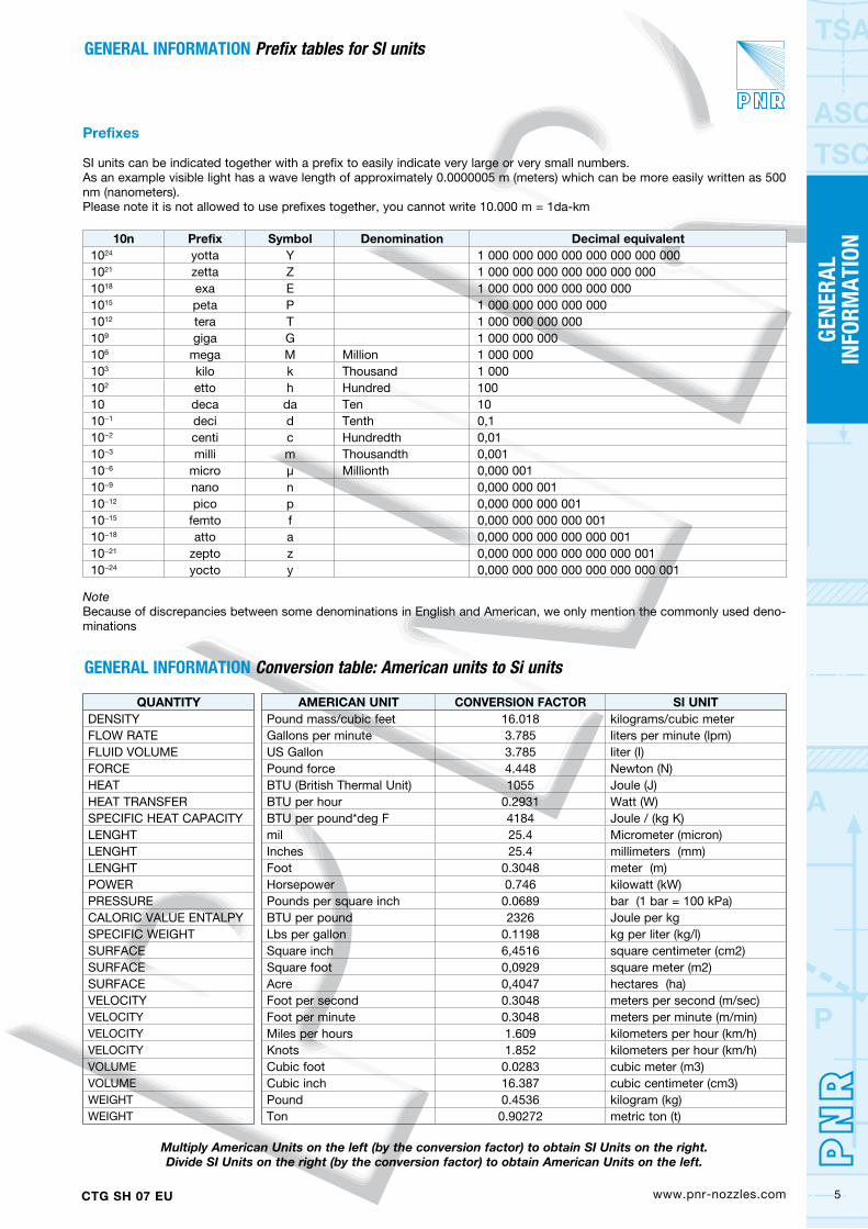
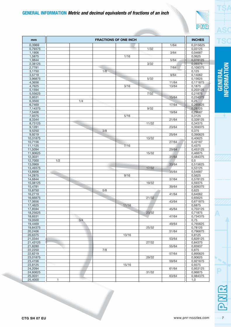
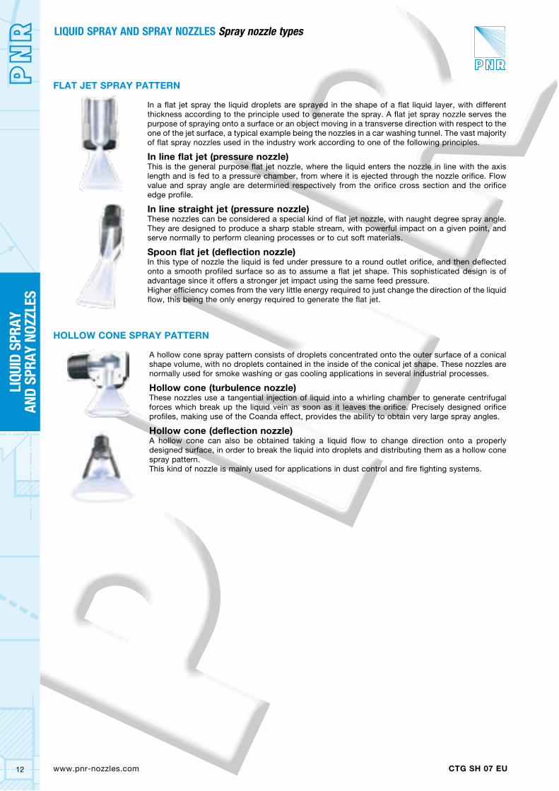
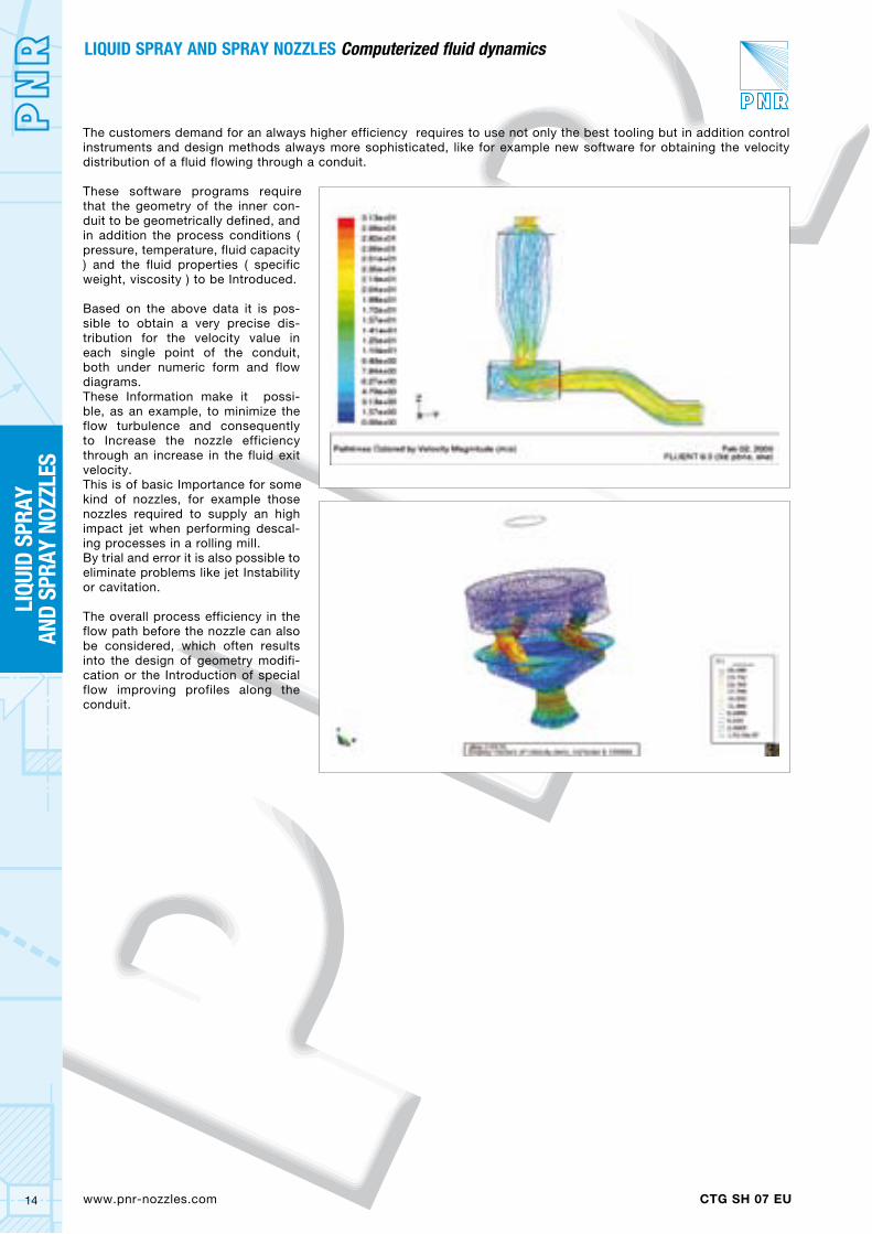
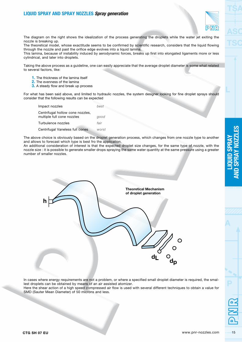
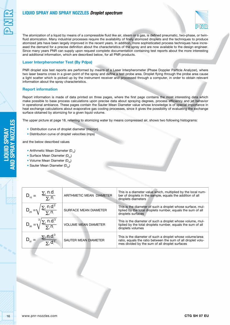
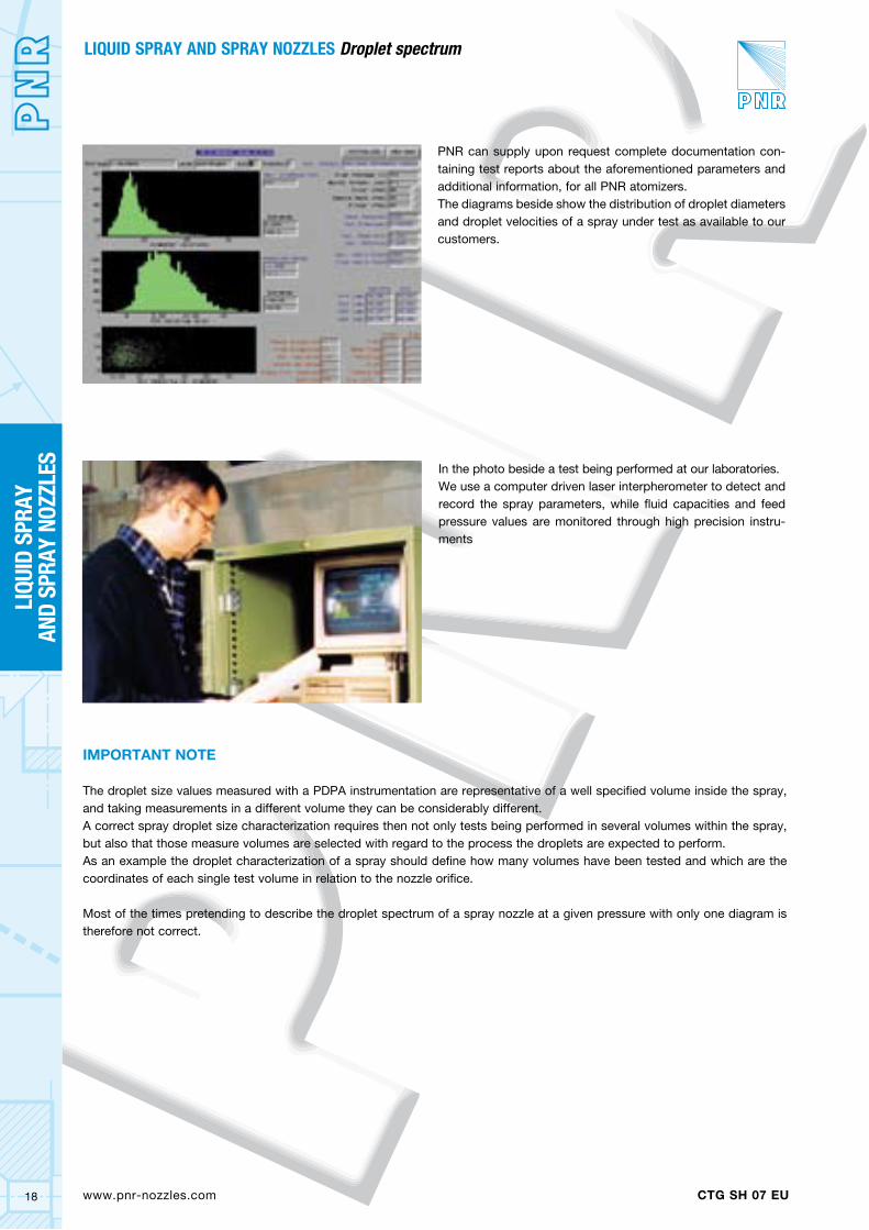
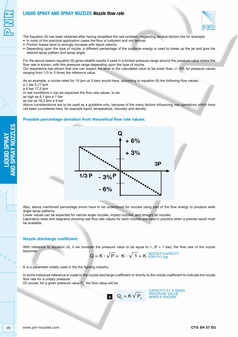
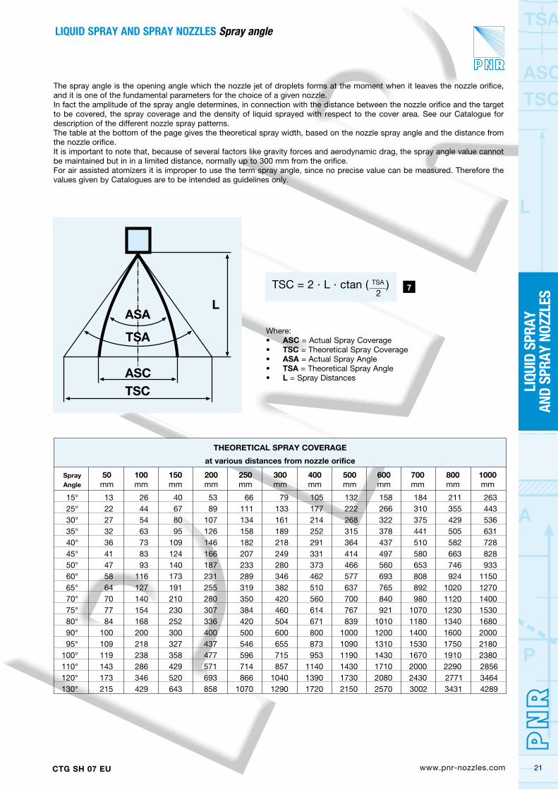
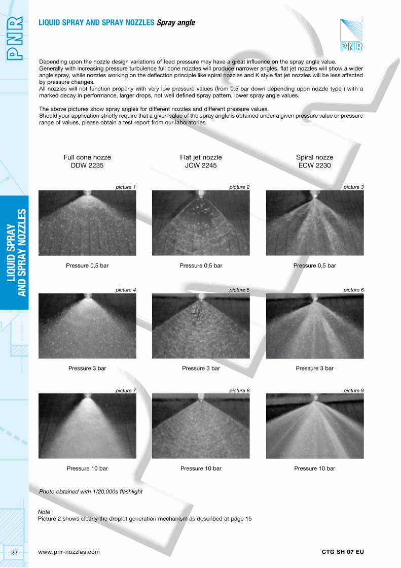
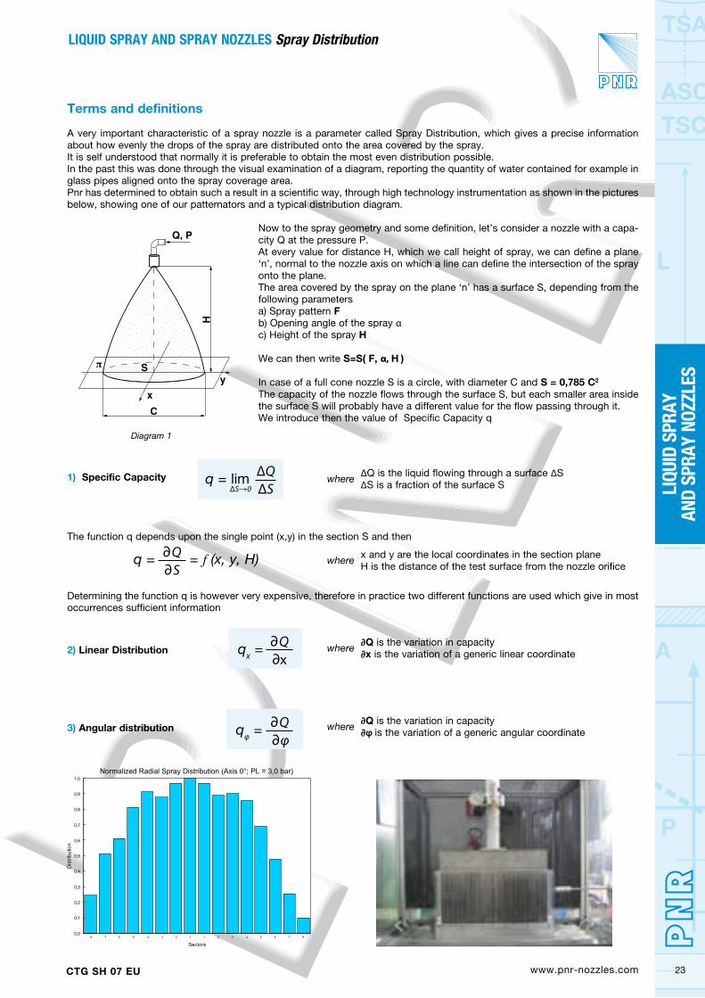
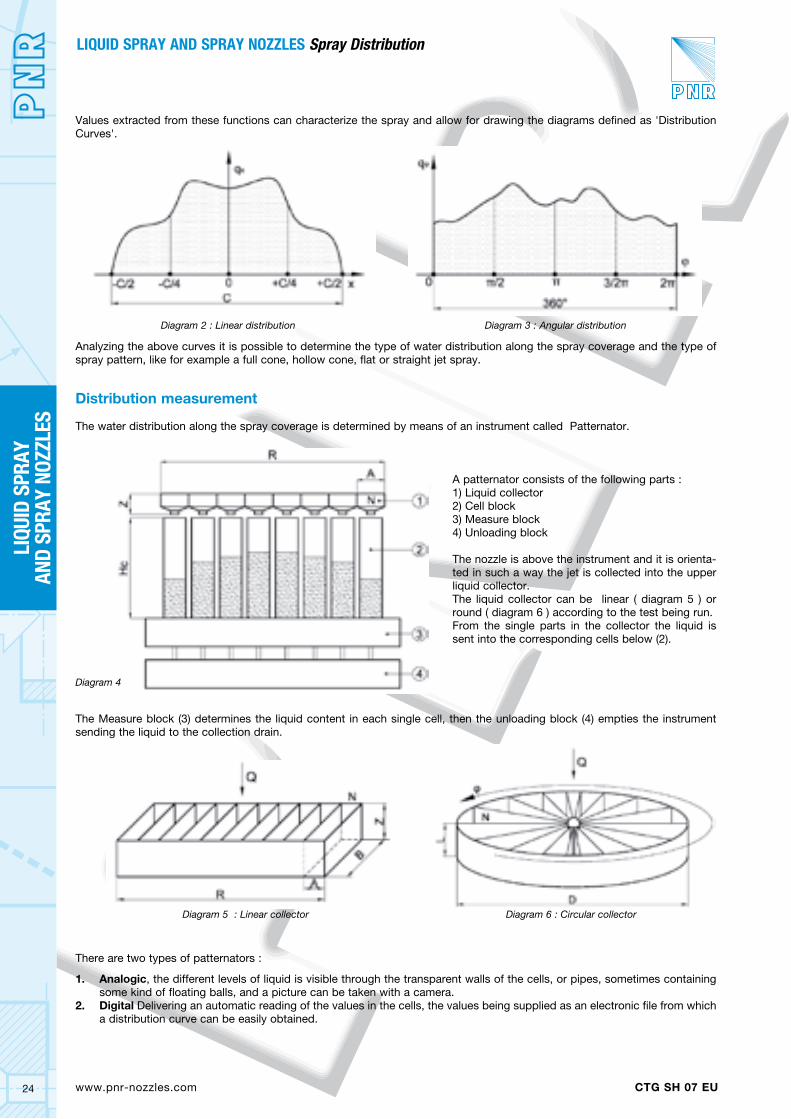
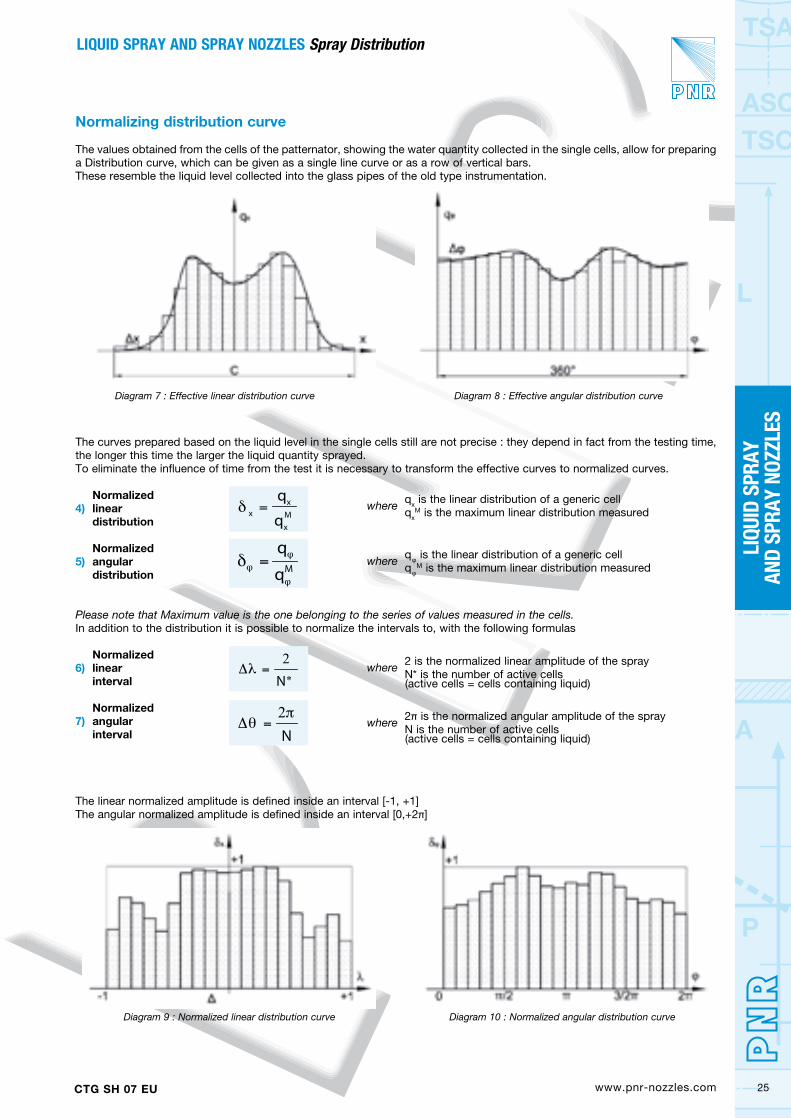
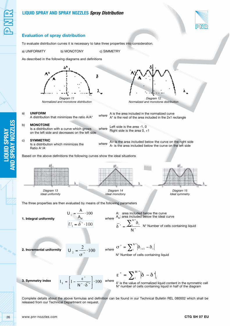
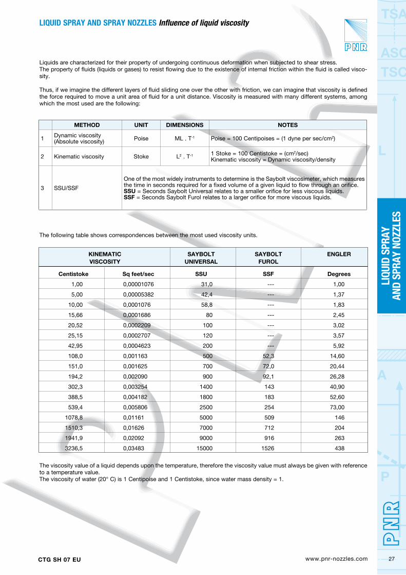
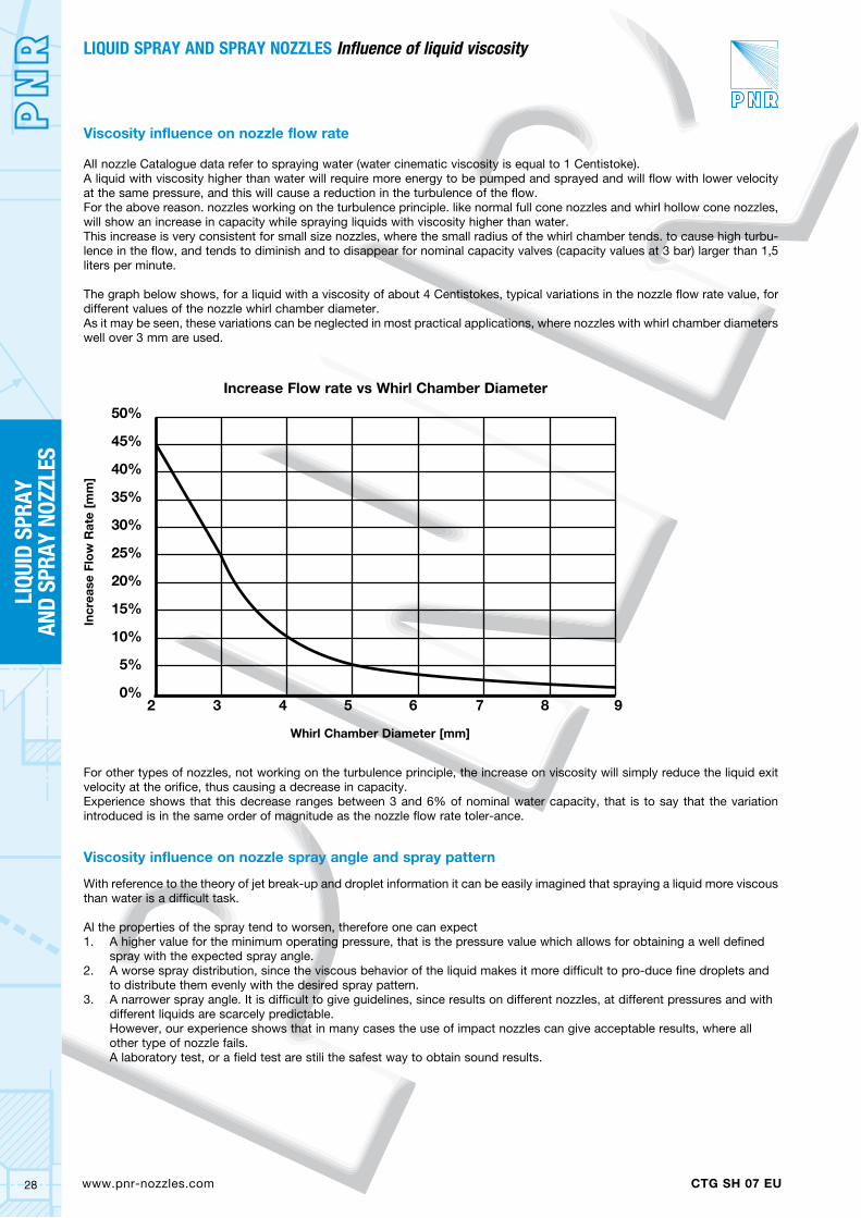
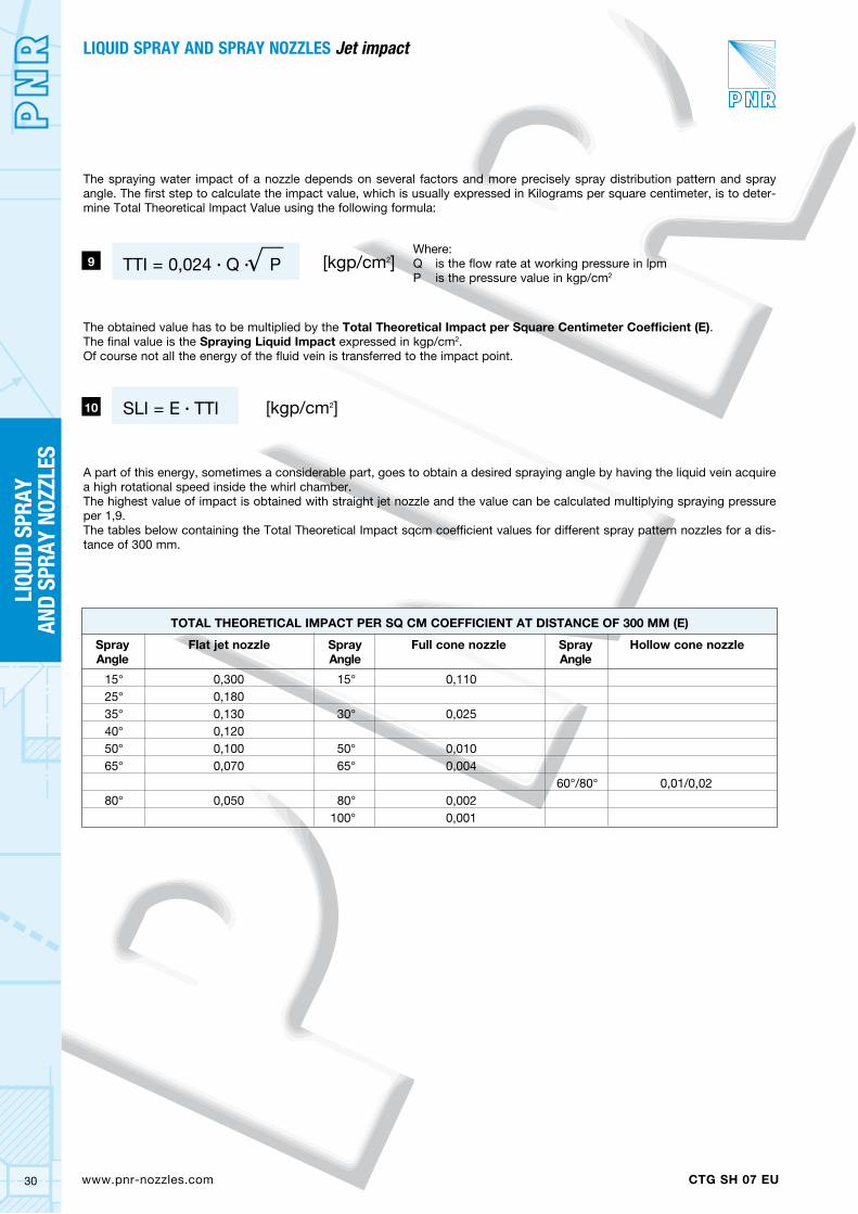
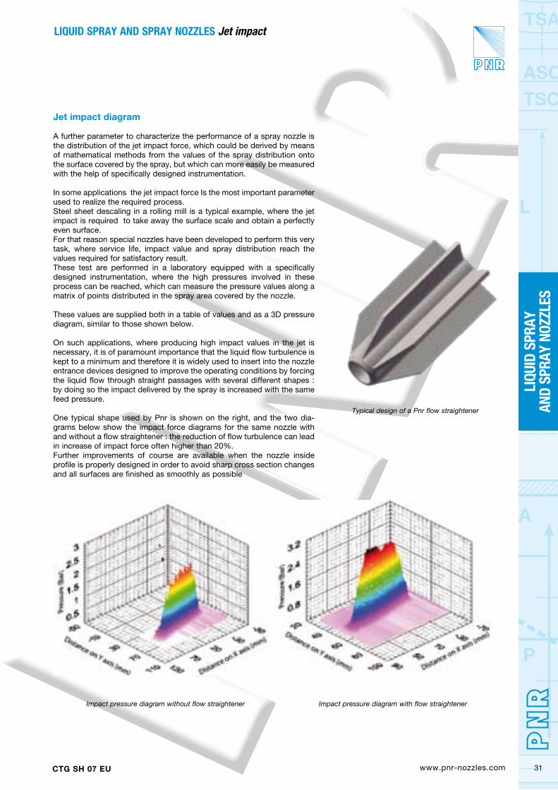
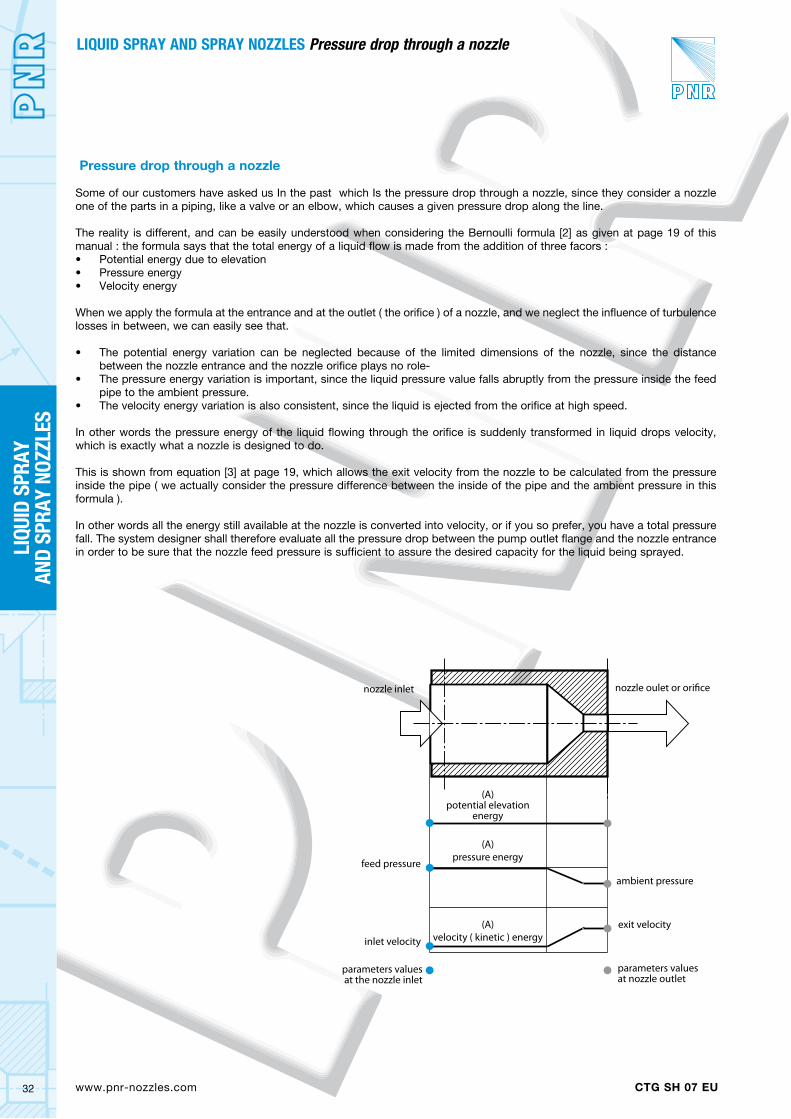
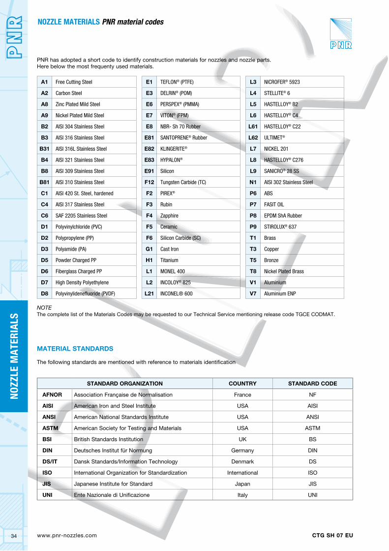
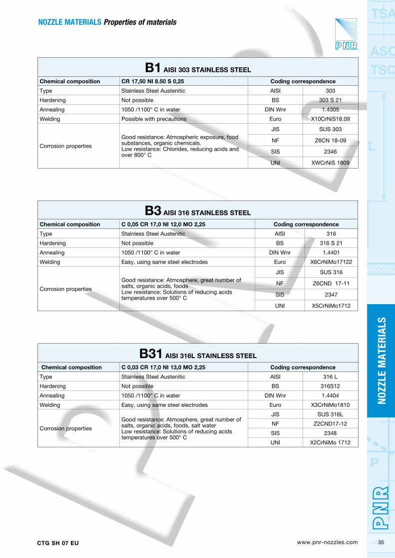
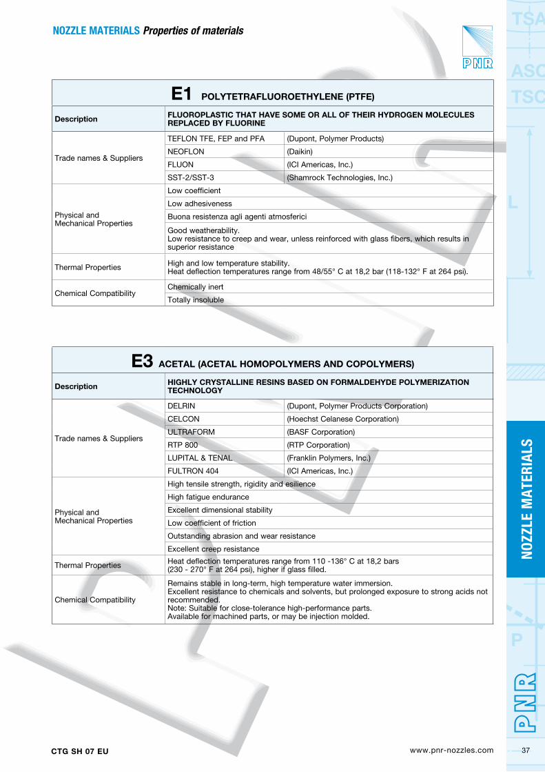
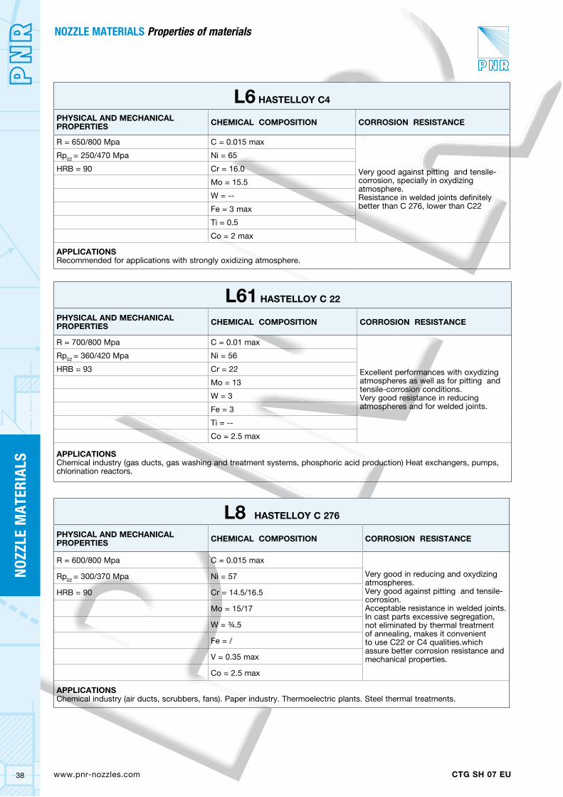
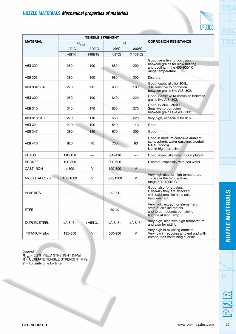
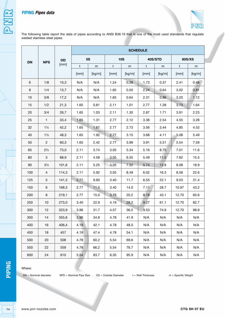
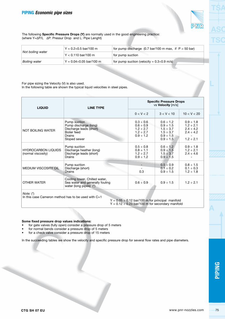
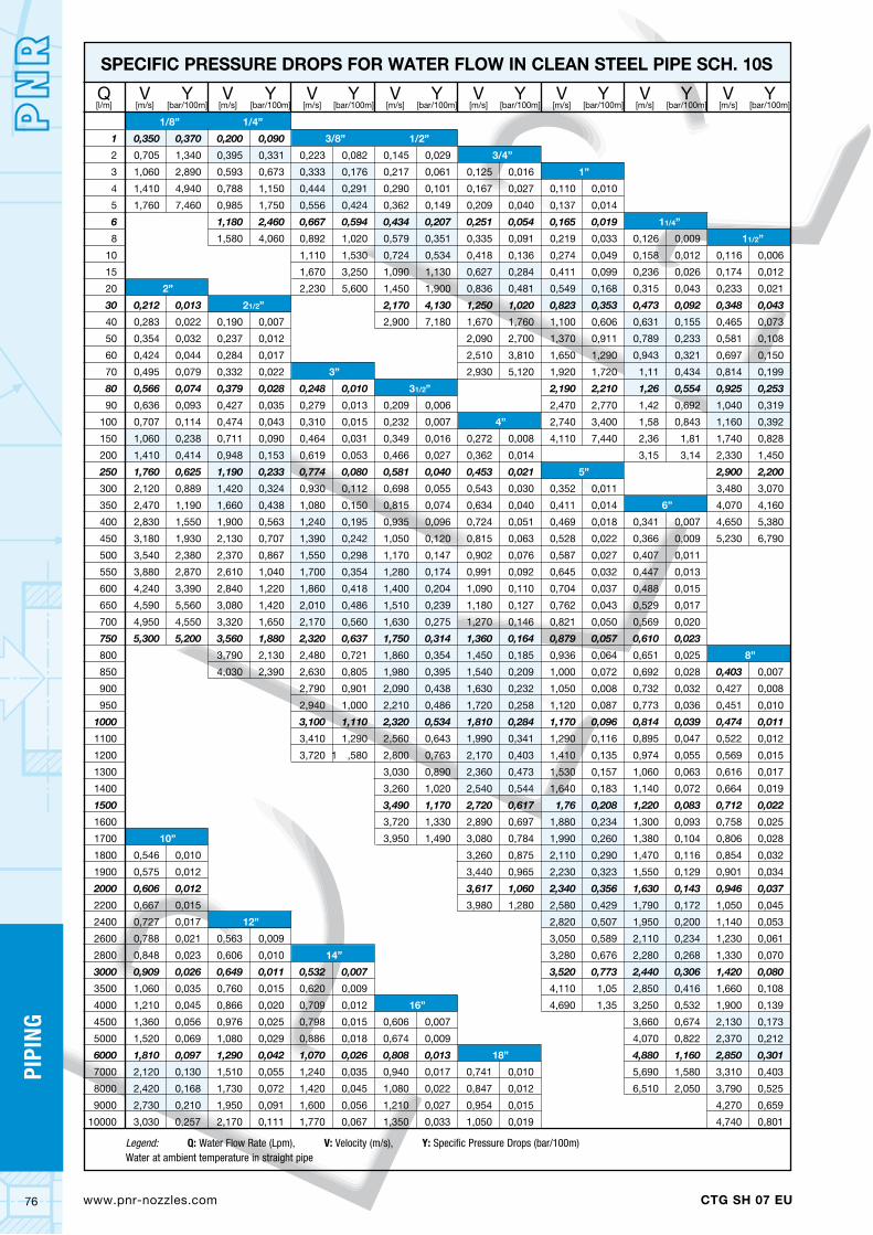
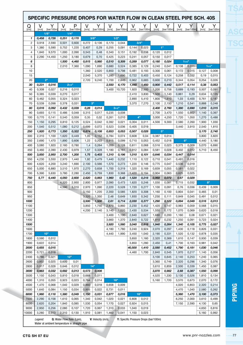
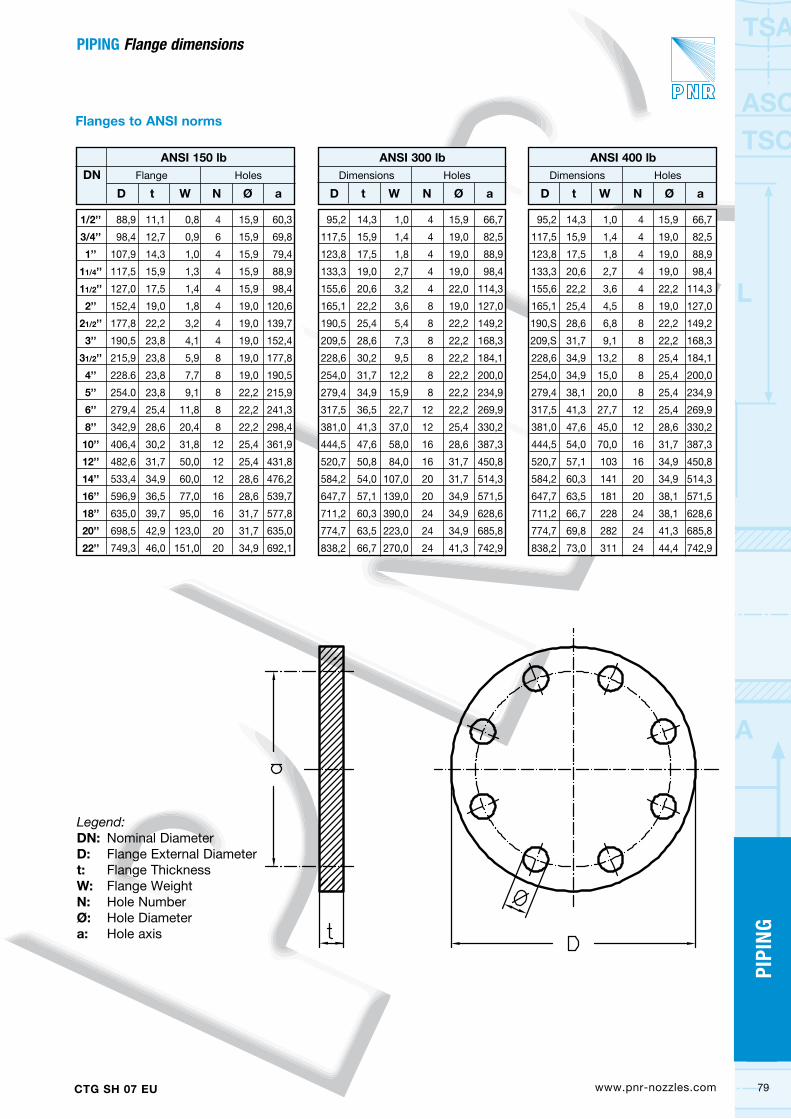
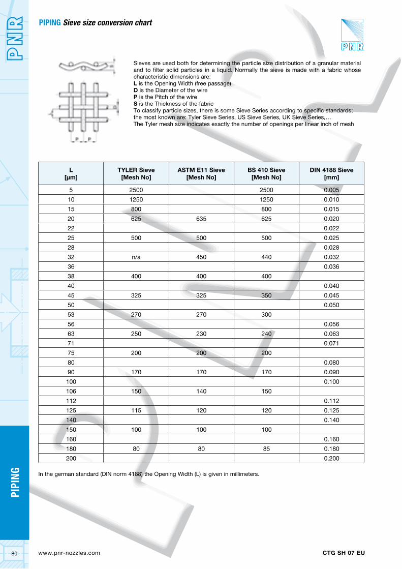
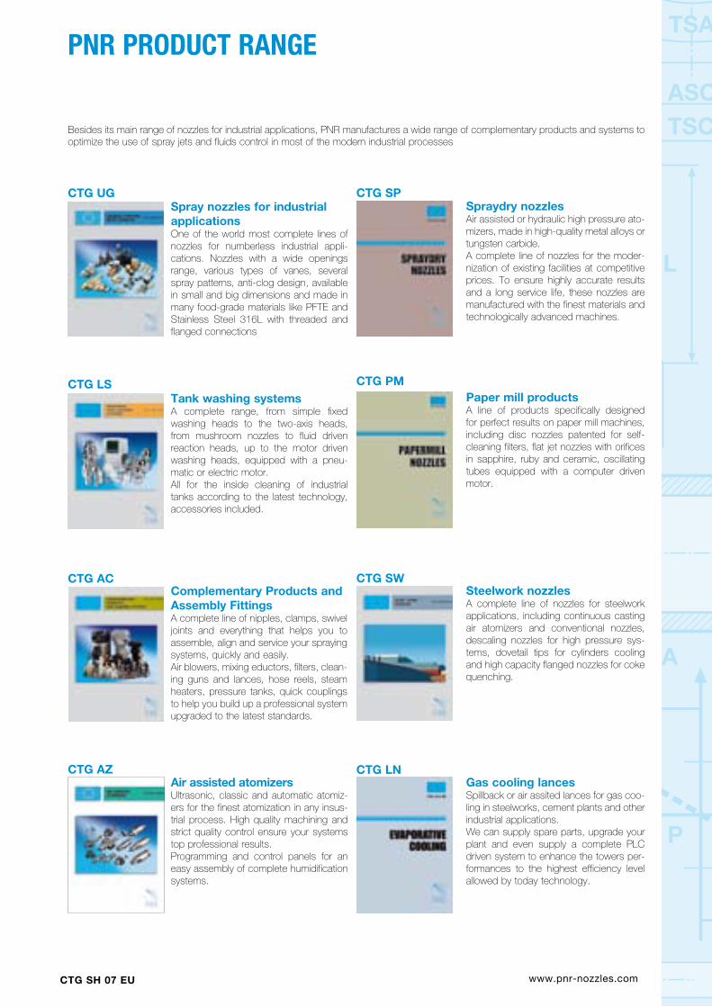