spray drying for processing of nanomaterials - iopscience
TRANSCRIPT

Journal of Physics Conference Series
OPEN ACCESS
Spray drying for processing of nanomaterialsTo cite this article Jesper Saeligderup Lindeloslashv and Michael Wahlberg 2009 J Phys Conf Ser 170012027
View the article online for updates and enhancements
You may also likeThe Effect of Maltodextrin Concentrationand Inlet Air Temperature on Spray DriedCentella Asiatica L PowderM D Azhar U K Ibrahim N A M Zaki et al
-
Enhancing graphene oxide reinforcingpotential in composites by combined latexcompounding and spray dryingYingyan Mao Shubai Zhang DandanZhang et al
-
Pulverization of coffee silverskin extract asa source of antioxidantS Tan S P Kusumocahyo and D IWidiputri
-
This content was downloaded from IP address 1032375694 on 11022022 at 0458
Spray Drying for Processing of Nanomaterials
Jesper Saeligderup Lindeloslashv and Michael Wahlberg
GEA Niro Gladsaxevej 305 DK-2860 Soslashborg Denmark
E-mail jesperlindeloevgeagroupcom
Abstract Consolidation of nano-particles into micron-sized granules reduces the potential risks associated with handling nano-powders in dry form Spray drying is a one step granulation technique which can be designed for safe production of free flowing low dusty granules from suspensions of nano-particles Spray dried granules are well suited for subsequent processing into final products where the superior properties given by the nano-particles are retained A spray drier with bag filters inside the drying chamber and recycling of drying gas combined with containment valves are proposed as a safe process for granulation of potential hazardous nano-particles
1 Introduction Production of high-tech materials using nanoparticles is of great scientific interest as they are expected to yield products with superior characteristics Turning a product produced on a laboratory scale into a commercial product means that process equipment needs to be available at the required capacity using suitable technologies for handling nanomaterials and their special properties As long as health and environmental effects of nanomaterials are not fully understood the process technologies used should ensure the highest protection of operators and environment A well established method of processing is to have the nanomaterials dispersed in a suspension This significantly reduces the risks however having the nanomaterials in suspension has implications due to higher transport costs of the often relatively diluted suspension and for aqueous suspensions containing perishable components the durability may restrict this method Further in order to produce solid materials it is required that the nanomaterials are transformed into a dry form Spray drying produce a micronsized product from suspensions of nanoparticles nanocapsules and other components having dimensions in the nanometer range Hence the spray drying technology may establish a link between the nanomaterial synthesis and the traditional processes which can produce the actual end products using micronsized materials
Spray drying is a one step process where a liquid is atomized to micronsized droplets and dried by hot gas The drying occurs in an insulated chamber consisting of a cylindrical chamber with a conical bottom The hot drying gas is introduced through an air dispenser situated in the chamber roof Atomization is performed using different techniques Centrifugal atomizers pressure nozzles and air blast nozzles are the techniques most frequently used but others are available Drying time is from 1 to 5 seconds depending on the initial droplet size Due to the energy consumption used for evaporating solvent the drying gas is cooled to an outlet temperature typically between 50degC and 120degC depending on product and application The evaporative cooling means that the heat exposure of the product is relatively low and the final product temperature is often lower than the outlet temperature of the gas The separation of dried product from the drying gas is done using a cyclone a bag filter or both Spray drying is a quick and relatively low temperature process and the promising features of the
Nanosafe 2008 International Conference on Safe production and use of nanomaterials IOP PublishingJournal of Physics Conference Series 170 (2009) 012027 doi1010881742-65961701012027
ccopy 2009 IOP Publishing Ltd 1
nanocomponents are preserved By formulating the suspensions prior to spray drying re-dispersibility of the granules can be obtained
GEA Niro is specialized in the development design and engineering of liquid and powder processing equipments for the manufacture of products in powder granular or agglomerated form GEA Niro is recognized as the leading supplier of spray drying technologies for the food chemical and pharmaceutical industry For the past two years GEA Niro has worked on developing safe processing routes for production of non-dusty micronsized granules from formulated suspensions of nanoparticles Through the EU founded SAPHIR (Safe integrated amp controlled Production of High-tech multifunctional materials and their Recycling) project GEA Niro has been collaborating with its 21 project partners in optimizing all processes involved in the nanoparticles synthesis through to the production of final materials of ceramic nature for use in many different applications GEA Nirorsquos aim in this project is to utilize the spray drying technology for production of nanostructured granules which can be handled in its dry form or redispersed As part of this project and through other experiments performed in GEA Nirorsquos Test Centre in Copenhagen experience in handling a range of different nanomaterials (eg SiC SiO2 TiO2 Hydroxyapatite and carbon nanotubes) has been obtained using the spray drying process Generally results indicate that most suspensions of nanoparticles are easily dryable In fact results using the Drying Kinetic Analyzertrade (novel instrument for determining drying behaviour) have shown that the suspensions of ceramic nanoparticles tested have drying rates which are higher than other products dried in a spray drying system due to a longer constant rate drying period This means that one stage drying can be utilized which makes up for a relative simple spray drying system Micronsized granules may still produce dust if not treated with consideration An area where accidental release of dust can occur from the spray drying is during changing of product containers This risk can be removed by use of containment solutions Buckreg containment systems produced by GEA Pharma Systems are utilized in combination with the spray drying system for safe processing of nanomaterials GEA Nirorsquos pharmaceutical test plants are equipped with the Buck valve system to eliminate the risk of dust being released to the production environment Especially the Buck Hicoflexreg system is a containment interface for safe transfer of granules with a suitable containment level for use in nanomaterial processing systems
This paper presents results obtained during the SAPHIR project where spray drying has been utilized for production of a non-dusty product from a suspension of nano titanium dioxide The purpose has been to produce granules which can be used for coatings where the photo catalytic behaviour of the anatase phase of the titanium can be utilized To ensure easy handling of the coating equipment a mean granule size below 50 microm was required and the product should be free flowing Different spray drying configuration and drying parameters have been tested to find the optimum conditions for continued production of the product
2 Materials and Methods
21 Materials Titanium dioxide (Degussa Aeroxide TiO2 P25) having a specific surface area of 50 m2g was dispersed in an aqueous solution of Dispex N40 (Ciba) Through vigorous stirring a suspension containing 37 dry matter was obtained 2-Octananole was used as foam reducer Sieving of the suspension was conducted to remove lumps which otherwise would block the atomization nozzle The suspension was continuously stirred until spray drying
22 Nozzle characterisation The nozzle used for atomizing the suspension was a GEA Niro two fluid nozzle Nozzle characterization was done using a Malvern Spraytec (Malvern Instruments) with a setup shown in Figure 1
Nanosafe 2008 International Conference on Safe production and use of nanomaterials IOP PublishingJournal of Physics Conference Series 170 (2009) 012027 doi1010881742-65961701012027
2
Figure 1 Schematic illustration of the set-up for droplet size measurements by laser diffraction
Results of droplet size were recorded during atomizing water at a flow rate of 15 25 and 40 kgh using atomization gas flow rates between 1 and 20 kgh Knowledge of the spraying behaviour of the nozzle was used in selecting atomization conditions during spray drying
23 Spray drying A Mobile Minortrade (GEA Niro) spray dryer was used in four different configurations as illustrated in Figure 2
Figure 2 Different configurations of the Mobile Minor (MM) used in the experiments A SD-MM configuration with product outlets from cyclone and bag filter B SD-IF-MM configuration with bag filters placed inside the drying chamber and with product outlet under the chamber C SD configuration with fines return from the cyclone to the atomization zone and main powder outlet under the chamber D IFD-MM configuration with bag filters placed inside the drying chamber and with powder outlet from the integrated fluid bed
The plant has a 08 m chamber diameter with a cylindrical height of 065 and a 40deg cone angle Co-current drying was conducted with the atomization nozzle positioned in the centre of the hot gas dispenser A pneumatic hammer was mounted on the conical part of the chamber and was in operation during the experiments Nitrogen was used as drying gas The inlet drying gas rate was 80 kgh at temperatures between 155degC and 195degC and the outlet temperature was between 70degC and 90degC giving a feed rate between 2 and 5 kgh In using the IFD-MM configuration the inlet temperature to the fluid bed was 60degC at a rate sufficient to fluidize the granules The bag filters were cleaned during
Nanosafe 2008 International Conference on Safe production and use of nanomaterials IOP PublishingJournal of Physics Conference Series 170 (2009) 012027 doi1010881742-65961701012027
3
operation by back flush purging using nitrogen gas at 2 bar(g) Process parameters were continuously recorded during operation
24 Granule characterisation The granule size was measured using a Mastersizer 2000 (Malvern Instruments) equipped with a dry feeding unit (Scirocco) dispersing the sample at 05 bar Three size values are reported D10 is the size where 90 (volume) of the population are larger D50 is the median size and D90 is the size where 10 of the population is larger
Residual moisture content was measured using a Halogen Moisture Analyser (HR73 Mettler Toledo) at 105degC
Granule morphology was investigated at Technological Institute Center for Micro Technology and Surface Analysis using a scanning electron microscope (Ultra55 Zeiss)
3 Results and discussions Initial test using the Drying Kinetic Analyzertrade (DKA) was performed The DKA is a novel instrument enabling real time drying kinetic measurements and morphology development observations on a levitated drop drying at carefully controlled conditions The drying behaviour determination of the nano-TiO2 suspensions at 37 solids showed that the drying rate was relatively high (data not shown) and that a spherical granule was produced The volume reduction during drying of the suspension droplets was 45 The final size of non-agglomerated granules produced by spray drying is determined by the droplet size obtained in the atomization process and the volume reduction occurring during drying The volume reduction is often dependent on the drying temperatures Hence the drying behaviour determination should be done at the same temperature as during spray drying
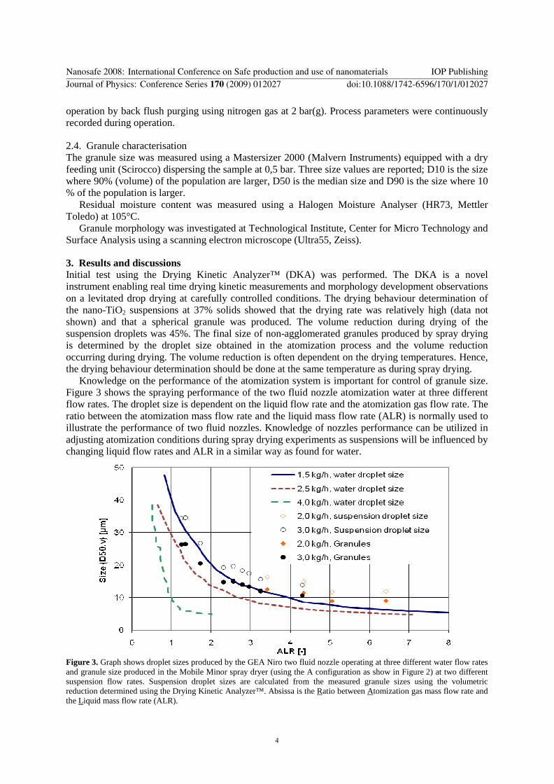
Knowledge on the performance of the atomization system is important for control of granule size Figure 3 shows the spraying performance of the two fluid nozzle atomization water at three different flow rates The droplet size is dependent on the liquid flow rate and the atomization gas flow rate The ratio between the atomization mass flow rate and the liquid mass flow rate (ALR) is normally used to illustrate the performance of two fluid nozzles Knowledge of nozzles performance can be utilized in adjusting atomization conditions during spray drying experiments as suspensions will be influenced by changing liquid flow rates and ALR in a similar way as found for water
Figure 3 Graph shows droplet sizes produced by the GEA Niro two fluid nozzle operating at three different water flow rates and granule size produced in the Mobile Minor spray dryer (using the A configuration as show in Figure 2) at two different suspension flow rates Suspension droplet sizes are calculated from the measured granule sizes using the volumetric reduction determined using the Drying Kinetic Analyzertrade Absissa is the Ratio between Atomization gas mass flow rate and the Liquid mass flow rate (ALR)
Nanosafe 2008 International Conference on Safe production and use of nanomaterials IOP PublishingJournal of Physics Conference Series 170 (2009) 012027 doi1010881742-65961701012027
4
The size of spray dried granules obtained at a feed capacity of 20 kgh and 30 kgh are shown in Figure 3 The calculated droplet sizes of the suspensions follow the same tendency as that found for water atomization In producing a non-dusty product the granules should be as large as possible In this case however the mean size (D50) should not exceed 50 microm Different spray drying configurations have been utilized in producing a product which has a D10 (granules size where 10 (volume) of the population having a smaller size ie dusty part of the population) as high as possible while keeping the D50 under the 50 microm Table 1 shows process parameters granule size and residual moisture content from spray drying experiments using the four different configurations
Table 1 Selected results from spray drying in four different configurations
Description Unit Plant configuration (see figure 2)
A B C D
Feed rate kgh 31 29 28 50
ALR - 14 13 26 35
Inlet gas temperature degC 154 182 160 195
Outlet gas temperature degC 82 79 84 71
Granule size
D(10 V) microm 91 11 142 17
D(50 V) microm 261 32 392 43
D(90 V) microm 751 87 912 120
Residual moisture 091 05 042 03 1 Data from cyclone fraction 2 Data from chamber fraction
By using spray drying configuration A the finest part of the population is not collected by the cyclone Hence two fractions are obtained The cyclone fraction has a suitable granule size but the bag filter fraction contains a very dusty product with a D50 of only 5 microm However only 5 of the total mass produced was collected under the bag filter Having two fractions of a product always gives rise to questions on what to do with the non-spec fraction Often it can be redispersed and mixed with the next production however avoiding two fractions is preferable Figure 4 shows SEM pictures of the granule morphology obtained using the four different configurations In plant configuration A individual spherical granules were produced as expected from the drying behaviour analysis Slightly higher tendency for agglomerated granules was obtained for plant configuration B The reason is that the fine part of the population will stay in the SD-IF chamber until agglomerated with bigger wet droplets and become sufficiently heavy to fall to the product container at the bottom Agglomeration is an efficient way to remove the finest granules from a population by agglomerating them to bigger granules This agglomeration process is forced using plant configuration C where the granules collected by the cyclone were returned to the atomization zone Examples of such agglomerated particles are seen in Figure 4 C Table 1 also shows that even though atomization has occurred at a higher ALR in the plant configuration C compared to configuration B the mean granule size was larger Again using configuration C gives rise to a non-spec fraction collected under the bag filter containing very dusty product and this is not optimal even though that the amount was limited Agglomeration is very distinct for granules produced using configuration D The agglomeration occurred in a random way as in the B configuration but the fluid bed function as a classifier by blowing off the finest granules Control of the granule size using configuration D was very difficult and having a mean granule size below 50 microm was only obtained for a relatively short time
Figure 5 shows a SEM picture of granules produced using configuration A One of the granules has become damaged in the process by either high shear or impact with the production equipment No binders were used in the suspension preparation and this limits the granule resistance to shear and impact that may occur especially in the cyclone or in the duct from the chamber In the cases where binders need to be avoided a low shear process should be considered to ensure that granule damage is kept at a minimum
Nanosafe 2008 International Conference on Safe production and use of nanomaterials IOP PublishingJournal of Physics Conference Series 170 (2009) 012027 doi1010881742-65961701012027
5
Plant configuration A
Plant configuration B
Plant configuration C
Plant configuration D
Figure 4 SEM pictures of granules produced on spray drying plants in four different configurations (A B C and D as shown in Figure 2)
Figure 5 SEM picture of granules produced on the spray dying plant in configuration A as shown in Figure 2
With the four different configurations tested configuration B appears to be the most attractive solution as it is a simple low shear system it produces only one fraction it is easy to control and it confines all granules inside the chamber This configuration has been utilized on other suspensions of nanomaterials where it also proved to be a suitable configuration utilising that the suspensions of nanoparticles dry relatively easily
Safety issues in spray drying involves a number of individual risks which need to be tackled eg dust explosion solvent explosion hot surfaces and emission of granules to the production
Nanosafe 2008 International Conference on Safe production and use of nanomaterials IOP PublishingJournal of Physics Conference Series 170 (2009) 012027 doi1010881742-65961701012027
6
environment These risks are to be considered both with the plant in operation and during cleaning The risks relating to explosions and hot surfaces is relatively trivial and are routinely tackled doing GEA Nirorsquos design of spray drying equipment Also risk of emission of granules is routinely tackled however with the health concerns associated by dealing with nanostructured granules special emphasis should be laid on this risk The atomization step produces micronsized droplets which dry to granules still in the micronsize range This means that the granules produced during spray drying are much easier to control compared to nanopowders as they will remain in the area of where emission has occurred Even though release of granules from the spray drying plant should be avoided This risk can be eliminated using a closed circuit plant as the one shown in Figure 6 This plant operates as the plant configuration B but with a HEPA filter placed after the bag filters to ensure complete confinement of the nanomaterials Further a condenser is used to condense the vapours in the outlet drying gas which means that the gas can be reused after reheating it to the inlet temperature The exhaust flow is very small compared to a normal open plant Loss of granules during change of product container is eliminated through the use of the Hicoflexreg system from Buckreg (Figure 6 b c) The proposed plant is a Mobile Minor sized plant having a capacity up to 5 kgh The plant can be scaled to the full size range that GEA Niro supplies but in each case the design and level of safety should be selected on the basis of a risk evaluation based on the environmental and health implications with the products to process a)
b)
c)
Figure 6 a) SD-IF-MM-CC plant for safe spray drying of nanomaterials b) Hicoflexreg in docked mode c) Hicoflexreg in undocked mode
4 Conclusions This study demonstrates that spray drying can successfully produce a non-dusty micronsized granulated product from suspensions of nanomaterials Four different configurations were tested for spray drying a suspension of nano-TiO2 It was concluded that the SD-IF-MM configuration was the optimal configuration for this particular product A closed circuit configuration of this plant equipped with the Hicoflexreg system would enable safe processing of nanomaterials
Acknowledgement We gratefully acknowledge founding obtained from the European Commission through the 6th framework programme as part of the SAPHIR project (httpwwwsaphir-projecteu) SAPHIR partner CERAM is acknowledge for developing the recipe for TiO2 suspension preparation
Nanosafe 2008 International Conference on Safe production and use of nanomaterials IOP PublishingJournal of Physics Conference Series 170 (2009) 012027 doi1010881742-65961701012027
7

Spray Drying for Processing of Nanomaterials
Jesper Saeligderup Lindeloslashv and Michael Wahlberg
GEA Niro Gladsaxevej 305 DK-2860 Soslashborg Denmark
E-mail jesperlindeloevgeagroupcom
Abstract Consolidation of nano-particles into micron-sized granules reduces the potential risks associated with handling nano-powders in dry form Spray drying is a one step granulation technique which can be designed for safe production of free flowing low dusty granules from suspensions of nano-particles Spray dried granules are well suited for subsequent processing into final products where the superior properties given by the nano-particles are retained A spray drier with bag filters inside the drying chamber and recycling of drying gas combined with containment valves are proposed as a safe process for granulation of potential hazardous nano-particles
1 Introduction Production of high-tech materials using nanoparticles is of great scientific interest as they are expected to yield products with superior characteristics Turning a product produced on a laboratory scale into a commercial product means that process equipment needs to be available at the required capacity using suitable technologies for handling nanomaterials and their special properties As long as health and environmental effects of nanomaterials are not fully understood the process technologies used should ensure the highest protection of operators and environment A well established method of processing is to have the nanomaterials dispersed in a suspension This significantly reduces the risks however having the nanomaterials in suspension has implications due to higher transport costs of the often relatively diluted suspension and for aqueous suspensions containing perishable components the durability may restrict this method Further in order to produce solid materials it is required that the nanomaterials are transformed into a dry form Spray drying produce a micronsized product from suspensions of nanoparticles nanocapsules and other components having dimensions in the nanometer range Hence the spray drying technology may establish a link between the nanomaterial synthesis and the traditional processes which can produce the actual end products using micronsized materials
Spray drying is a one step process where a liquid is atomized to micronsized droplets and dried by hot gas The drying occurs in an insulated chamber consisting of a cylindrical chamber with a conical bottom The hot drying gas is introduced through an air dispenser situated in the chamber roof Atomization is performed using different techniques Centrifugal atomizers pressure nozzles and air blast nozzles are the techniques most frequently used but others are available Drying time is from 1 to 5 seconds depending on the initial droplet size Due to the energy consumption used for evaporating solvent the drying gas is cooled to an outlet temperature typically between 50degC and 120degC depending on product and application The evaporative cooling means that the heat exposure of the product is relatively low and the final product temperature is often lower than the outlet temperature of the gas The separation of dried product from the drying gas is done using a cyclone a bag filter or both Spray drying is a quick and relatively low temperature process and the promising features of the
Nanosafe 2008 International Conference on Safe production and use of nanomaterials IOP PublishingJournal of Physics Conference Series 170 (2009) 012027 doi1010881742-65961701012027
ccopy 2009 IOP Publishing Ltd 1
nanocomponents are preserved By formulating the suspensions prior to spray drying re-dispersibility of the granules can be obtained
GEA Niro is specialized in the development design and engineering of liquid and powder processing equipments for the manufacture of products in powder granular or agglomerated form GEA Niro is recognized as the leading supplier of spray drying technologies for the food chemical and pharmaceutical industry For the past two years GEA Niro has worked on developing safe processing routes for production of non-dusty micronsized granules from formulated suspensions of nanoparticles Through the EU founded SAPHIR (Safe integrated amp controlled Production of High-tech multifunctional materials and their Recycling) project GEA Niro has been collaborating with its 21 project partners in optimizing all processes involved in the nanoparticles synthesis through to the production of final materials of ceramic nature for use in many different applications GEA Nirorsquos aim in this project is to utilize the spray drying technology for production of nanostructured granules which can be handled in its dry form or redispersed As part of this project and through other experiments performed in GEA Nirorsquos Test Centre in Copenhagen experience in handling a range of different nanomaterials (eg SiC SiO2 TiO2 Hydroxyapatite and carbon nanotubes) has been obtained using the spray drying process Generally results indicate that most suspensions of nanoparticles are easily dryable In fact results using the Drying Kinetic Analyzertrade (novel instrument for determining drying behaviour) have shown that the suspensions of ceramic nanoparticles tested have drying rates which are higher than other products dried in a spray drying system due to a longer constant rate drying period This means that one stage drying can be utilized which makes up for a relative simple spray drying system Micronsized granules may still produce dust if not treated with consideration An area where accidental release of dust can occur from the spray drying is during changing of product containers This risk can be removed by use of containment solutions Buckreg containment systems produced by GEA Pharma Systems are utilized in combination with the spray drying system for safe processing of nanomaterials GEA Nirorsquos pharmaceutical test plants are equipped with the Buck valve system to eliminate the risk of dust being released to the production environment Especially the Buck Hicoflexreg system is a containment interface for safe transfer of granules with a suitable containment level for use in nanomaterial processing systems
This paper presents results obtained during the SAPHIR project where spray drying has been utilized for production of a non-dusty product from a suspension of nano titanium dioxide The purpose has been to produce granules which can be used for coatings where the photo catalytic behaviour of the anatase phase of the titanium can be utilized To ensure easy handling of the coating equipment a mean granule size below 50 microm was required and the product should be free flowing Different spray drying configuration and drying parameters have been tested to find the optimum conditions for continued production of the product
2 Materials and Methods
21 Materials Titanium dioxide (Degussa Aeroxide TiO2 P25) having a specific surface area of 50 m2g was dispersed in an aqueous solution of Dispex N40 (Ciba) Through vigorous stirring a suspension containing 37 dry matter was obtained 2-Octananole was used as foam reducer Sieving of the suspension was conducted to remove lumps which otherwise would block the atomization nozzle The suspension was continuously stirred until spray drying
22 Nozzle characterisation The nozzle used for atomizing the suspension was a GEA Niro two fluid nozzle Nozzle characterization was done using a Malvern Spraytec (Malvern Instruments) with a setup shown in Figure 1
Nanosafe 2008 International Conference on Safe production and use of nanomaterials IOP PublishingJournal of Physics Conference Series 170 (2009) 012027 doi1010881742-65961701012027
2
Figure 1 Schematic illustration of the set-up for droplet size measurements by laser diffraction
Results of droplet size were recorded during atomizing water at a flow rate of 15 25 and 40 kgh using atomization gas flow rates between 1 and 20 kgh Knowledge of the spraying behaviour of the nozzle was used in selecting atomization conditions during spray drying
23 Spray drying A Mobile Minortrade (GEA Niro) spray dryer was used in four different configurations as illustrated in Figure 2
Figure 2 Different configurations of the Mobile Minor (MM) used in the experiments A SD-MM configuration with product outlets from cyclone and bag filter B SD-IF-MM configuration with bag filters placed inside the drying chamber and with product outlet under the chamber C SD configuration with fines return from the cyclone to the atomization zone and main powder outlet under the chamber D IFD-MM configuration with bag filters placed inside the drying chamber and with powder outlet from the integrated fluid bed
The plant has a 08 m chamber diameter with a cylindrical height of 065 and a 40deg cone angle Co-current drying was conducted with the atomization nozzle positioned in the centre of the hot gas dispenser A pneumatic hammer was mounted on the conical part of the chamber and was in operation during the experiments Nitrogen was used as drying gas The inlet drying gas rate was 80 kgh at temperatures between 155degC and 195degC and the outlet temperature was between 70degC and 90degC giving a feed rate between 2 and 5 kgh In using the IFD-MM configuration the inlet temperature to the fluid bed was 60degC at a rate sufficient to fluidize the granules The bag filters were cleaned during
Nanosafe 2008 International Conference on Safe production and use of nanomaterials IOP PublishingJournal of Physics Conference Series 170 (2009) 012027 doi1010881742-65961701012027
3
operation by back flush purging using nitrogen gas at 2 bar(g) Process parameters were continuously recorded during operation
24 Granule characterisation The granule size was measured using a Mastersizer 2000 (Malvern Instruments) equipped with a dry feeding unit (Scirocco) dispersing the sample at 05 bar Three size values are reported D10 is the size where 90 (volume) of the population are larger D50 is the median size and D90 is the size where 10 of the population is larger
Residual moisture content was measured using a Halogen Moisture Analyser (HR73 Mettler Toledo) at 105degC
Granule morphology was investigated at Technological Institute Center for Micro Technology and Surface Analysis using a scanning electron microscope (Ultra55 Zeiss)
3 Results and discussions Initial test using the Drying Kinetic Analyzertrade (DKA) was performed The DKA is a novel instrument enabling real time drying kinetic measurements and morphology development observations on a levitated drop drying at carefully controlled conditions The drying behaviour determination of the nano-TiO2 suspensions at 37 solids showed that the drying rate was relatively high (data not shown) and that a spherical granule was produced The volume reduction during drying of the suspension droplets was 45 The final size of non-agglomerated granules produced by spray drying is determined by the droplet size obtained in the atomization process and the volume reduction occurring during drying The volume reduction is often dependent on the drying temperatures Hence the drying behaviour determination should be done at the same temperature as during spray drying
Knowledge on the performance of the atomization system is important for control of granule size Figure 3 shows the spraying performance of the two fluid nozzle atomization water at three different flow rates The droplet size is dependent on the liquid flow rate and the atomization gas flow rate The ratio between the atomization mass flow rate and the liquid mass flow rate (ALR) is normally used to illustrate the performance of two fluid nozzles Knowledge of nozzles performance can be utilized in adjusting atomization conditions during spray drying experiments as suspensions will be influenced by changing liquid flow rates and ALR in a similar way as found for water
Figure 3 Graph shows droplet sizes produced by the GEA Niro two fluid nozzle operating at three different water flow rates and granule size produced in the Mobile Minor spray dryer (using the A configuration as show in Figure 2) at two different suspension flow rates Suspension droplet sizes are calculated from the measured granule sizes using the volumetric reduction determined using the Drying Kinetic Analyzertrade Absissa is the Ratio between Atomization gas mass flow rate and the Liquid mass flow rate (ALR)
Nanosafe 2008 International Conference on Safe production and use of nanomaterials IOP PublishingJournal of Physics Conference Series 170 (2009) 012027 doi1010881742-65961701012027
4
The size of spray dried granules obtained at a feed capacity of 20 kgh and 30 kgh are shown in Figure 3 The calculated droplet sizes of the suspensions follow the same tendency as that found for water atomization In producing a non-dusty product the granules should be as large as possible In this case however the mean size (D50) should not exceed 50 microm Different spray drying configurations have been utilized in producing a product which has a D10 (granules size where 10 (volume) of the population having a smaller size ie dusty part of the population) as high as possible while keeping the D50 under the 50 microm Table 1 shows process parameters granule size and residual moisture content from spray drying experiments using the four different configurations
Table 1 Selected results from spray drying in four different configurations
Description Unit Plant configuration (see figure 2)
A B C D
Feed rate kgh 31 29 28 50
ALR - 14 13 26 35
Inlet gas temperature degC 154 182 160 195
Outlet gas temperature degC 82 79 84 71
Granule size
D(10 V) microm 91 11 142 17
D(50 V) microm 261 32 392 43
D(90 V) microm 751 87 912 120
Residual moisture 091 05 042 03 1 Data from cyclone fraction 2 Data from chamber fraction
By using spray drying configuration A the finest part of the population is not collected by the cyclone Hence two fractions are obtained The cyclone fraction has a suitable granule size but the bag filter fraction contains a very dusty product with a D50 of only 5 microm However only 5 of the total mass produced was collected under the bag filter Having two fractions of a product always gives rise to questions on what to do with the non-spec fraction Often it can be redispersed and mixed with the next production however avoiding two fractions is preferable Figure 4 shows SEM pictures of the granule morphology obtained using the four different configurations In plant configuration A individual spherical granules were produced as expected from the drying behaviour analysis Slightly higher tendency for agglomerated granules was obtained for plant configuration B The reason is that the fine part of the population will stay in the SD-IF chamber until agglomerated with bigger wet droplets and become sufficiently heavy to fall to the product container at the bottom Agglomeration is an efficient way to remove the finest granules from a population by agglomerating them to bigger granules This agglomeration process is forced using plant configuration C where the granules collected by the cyclone were returned to the atomization zone Examples of such agglomerated particles are seen in Figure 4 C Table 1 also shows that even though atomization has occurred at a higher ALR in the plant configuration C compared to configuration B the mean granule size was larger Again using configuration C gives rise to a non-spec fraction collected under the bag filter containing very dusty product and this is not optimal even though that the amount was limited Agglomeration is very distinct for granules produced using configuration D The agglomeration occurred in a random way as in the B configuration but the fluid bed function as a classifier by blowing off the finest granules Control of the granule size using configuration D was very difficult and having a mean granule size below 50 microm was only obtained for a relatively short time
Figure 5 shows a SEM picture of granules produced using configuration A One of the granules has become damaged in the process by either high shear or impact with the production equipment No binders were used in the suspension preparation and this limits the granule resistance to shear and impact that may occur especially in the cyclone or in the duct from the chamber In the cases where binders need to be avoided a low shear process should be considered to ensure that granule damage is kept at a minimum
Nanosafe 2008 International Conference on Safe production and use of nanomaterials IOP PublishingJournal of Physics Conference Series 170 (2009) 012027 doi1010881742-65961701012027
5
Plant configuration A
Plant configuration B
Plant configuration C
Plant configuration D
Figure 4 SEM pictures of granules produced on spray drying plants in four different configurations (A B C and D as shown in Figure 2)
Figure 5 SEM picture of granules produced on the spray dying plant in configuration A as shown in Figure 2
With the four different configurations tested configuration B appears to be the most attractive solution as it is a simple low shear system it produces only one fraction it is easy to control and it confines all granules inside the chamber This configuration has been utilized on other suspensions of nanomaterials where it also proved to be a suitable configuration utilising that the suspensions of nanoparticles dry relatively easily
Safety issues in spray drying involves a number of individual risks which need to be tackled eg dust explosion solvent explosion hot surfaces and emission of granules to the production
Nanosafe 2008 International Conference on Safe production and use of nanomaterials IOP PublishingJournal of Physics Conference Series 170 (2009) 012027 doi1010881742-65961701012027
6
environment These risks are to be considered both with the plant in operation and during cleaning The risks relating to explosions and hot surfaces is relatively trivial and are routinely tackled doing GEA Nirorsquos design of spray drying equipment Also risk of emission of granules is routinely tackled however with the health concerns associated by dealing with nanostructured granules special emphasis should be laid on this risk The atomization step produces micronsized droplets which dry to granules still in the micronsize range This means that the granules produced during spray drying are much easier to control compared to nanopowders as they will remain in the area of where emission has occurred Even though release of granules from the spray drying plant should be avoided This risk can be eliminated using a closed circuit plant as the one shown in Figure 6 This plant operates as the plant configuration B but with a HEPA filter placed after the bag filters to ensure complete confinement of the nanomaterials Further a condenser is used to condense the vapours in the outlet drying gas which means that the gas can be reused after reheating it to the inlet temperature The exhaust flow is very small compared to a normal open plant Loss of granules during change of product container is eliminated through the use of the Hicoflexreg system from Buckreg (Figure 6 b c) The proposed plant is a Mobile Minor sized plant having a capacity up to 5 kgh The plant can be scaled to the full size range that GEA Niro supplies but in each case the design and level of safety should be selected on the basis of a risk evaluation based on the environmental and health implications with the products to process a)
b)
c)
Figure 6 a) SD-IF-MM-CC plant for safe spray drying of nanomaterials b) Hicoflexreg in docked mode c) Hicoflexreg in undocked mode
4 Conclusions This study demonstrates that spray drying can successfully produce a non-dusty micronsized granulated product from suspensions of nanomaterials Four different configurations were tested for spray drying a suspension of nano-TiO2 It was concluded that the SD-IF-MM configuration was the optimal configuration for this particular product A closed circuit configuration of this plant equipped with the Hicoflexreg system would enable safe processing of nanomaterials
Acknowledgement We gratefully acknowledge founding obtained from the European Commission through the 6th framework programme as part of the SAPHIR project (httpwwwsaphir-projecteu) SAPHIR partner CERAM is acknowledge for developing the recipe for TiO2 suspension preparation
Nanosafe 2008 International Conference on Safe production and use of nanomaterials IOP PublishingJournal of Physics Conference Series 170 (2009) 012027 doi1010881742-65961701012027
7
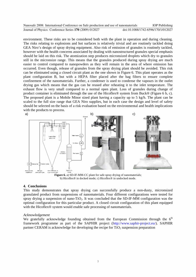