spray humidifier design ped ii final
TRANSCRIPT

Course No: - CL-304 Course Name: - Chemical Equipment Design-II
IIT-Guwahati
A report on designing of Spray Humidifier
Report Prepared By:- P.Yashaswini - 10010741 P.Sairahul Reddy- 10010742 Prerona Das- 10010744 Pritom Sharma- 10010745
Date of submission:-25/10/12
CONTENTS
1.) Counter Current Front view of our design
2.) Co current Front view of our design 3.) Objective 4.) Assumptions 5.) Design calculation
a.) Process Design
i.) Calculation of Cross Section area of the spray chamber
ii.) Calculation of diameter of the spray chamber
iii.) Calculation of length and Volume of the spray chamber
iv.) Calculation of kg. of water sprayed in the spray chamber
v.) Calculation of rate of the make up water needed to be supplied to the spray chamber
vi.) Calculation of rate of the Re circulated water
vii.) Calculation of number of power required to operate the nozzle
viii.) Calculation of number of nozzles required

b.) Mechanical Design i.) Thickness of the spray chamber ii.) Head design: Conical head iii.) Support Design: Saddle support iv.) Nozzle in shell for water outlet v.) Design of Tank vi.) Design of drift eliminators vii.) Design Ring type flange with a plain
face viii.) TORNADO WATER FILTER ix.) AIR FILTER x.) Centrifugal Monoblock Pumps xi.) BLOWERS
c.) Cost calculation d.) Power consumption in a year e.) Back Calculation for checking the overdesign f.) GUI using MATLAB based functions:

Counter Current Front view of our design
Co current Front view of our design
As we are assuming no temperature change of the water, hence the log mean
temperature difference remains same for both the case. So, theoretically our
design specifications are valid for both co and counter current design.
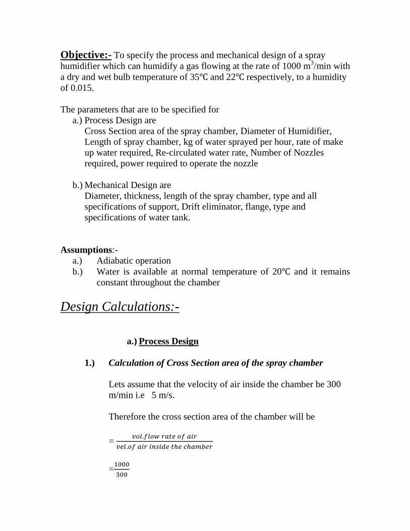
Objective:- To specify the process and mechanical design of a spray
humidifier which can humidify a gas flowing at the rate of 1000 m3/min with
a dry and wet bulb temperature of 35 and 22 respectively, to a humidity
of 0.015.
The parameters that are to be specified for
a.) Process Design are
Cross Section area of the spray chamber, Diameter of Humidifier,
Length of spray chamber, kg of water sprayed per hour, rate of make
up water required, Re-circulated water rate, Number of Nozzles
required, power required to operate the nozzle
b.) Mechanical Design are
Diameter, thickness, length of the spray chamber, type and all
specifications of support, Drift eliminator, flange, type and
specifications of water tank.
Assumptions:-
a.) Adiabatic operation
b.) Water is available at normal temperature of 20 and it remains
constant throughout the chamber
Design Calculations:-
a.) Process Design
1.) Calculation of Cross Section area of the spray chamber
Lets assume that the velocity of air inside the chamber be 300
m/min i.e 5 m/s.
Therefore the cross section area of the chamber will be
=
=

=3.333 m2
2.) Calculation of diameter of the spray chamber
The diameter of the chamber is given by
=√
=√
=2.06065 m
3.) Calculation of length and Volume of the spray chamber
The volume of the spray humidifier can be calculated by using
the equation
Sensible heat loss by the air = heat transfer co efficient
Volume of the spray chamber
Log mean temperature difference
--------------------------------------------------(1)
Log mean temperature difference
Temperature of the inlet air, T1 = 35 = 95
Temperature of the outlet air, T2 = 25 = 77
Temperature of the inlet water, T3 = 20 = 68
Now as per our assumption temperature of water remains
unchanged
Temperature of the outlet water, T4 = 20

Log mean temperature difference = ( ) ( )
(
)
= ( ) ( )
(
)
=
( )
= 16.3843 --------------------------(2)
heat transfer co efficient:
for air water system heat transfer co-efficient can be assumed to be =
90 Btu/ .hr.ft3---------------(3)
Sensible heat loss by the air
Let us take the reference temperature to be 32
Now
Mass flow rate of air =
Vol flow rate of air = 1000 m3/min
Humid vol of air at 35 can be calculated by using the
equation
( ⁄
⁄ ) (
)
= 0.8875 m3/kg of dry air
Mass flow rate of air =
Kg of dry air/min
= 1126.8 Kg of dry air/min
= 67607 Kg of dry air/hr
= 149047.9117 lb of dry air/hr

Inlet Humidity
Let the initial Humidity of air be Y1
We have inlet dry bulb temperature, TG= 35
Wet bulb temperature, Tw=22
We have from the Lewis relation,
TG- Tw=
(Saturated Humidity-Humidity)
At 35 latent heat of water is 2450 kj/kg of water
Specific heat of air is = (1.005+1.88 Y1) kj/k.kg of dry air
We have
TG- Tw=
(Saturated Humidity-Y1)
Saturated humidity =
( )
Saturated Vapour Pressure can be calculated from Antoine’s
equation
=exp(11.96481-
)
=0.02572 bar
=2572 pa
Atmospheric pressure = 101325 pa
Saturated Humidity =
( )
=0.0162
⁄
The equation becomes
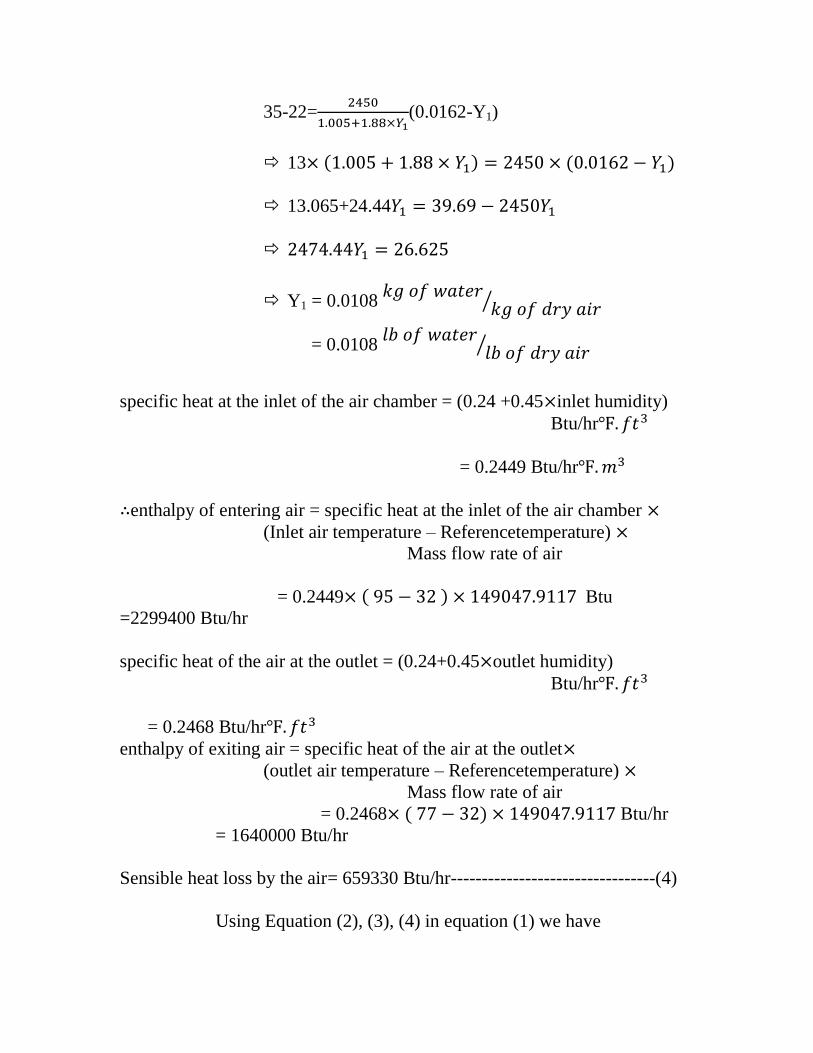
35-22=
(0.0162-Y1)
13 ( ) ( )
13.065+24.44
Y1 = 0.0108
⁄
= 0.0108
⁄
specific heat at the inlet of the air chamber = (0.24 +0.45 inlet humidity)
Btu/hr
= 0.2449 Btu/hr
enthalpy of entering air = specific heat at the inlet of the air chamber
(Inlet air temperature – Referencetemperature)
Mass flow rate of air
= 0.2449 ( ) Btu
=2299400 Btu/hr
specific heat of the air at the outlet = (0.24+0.45 outlet humidity)
Btu/hr
= 0.2468 Btu/hr
enthalpy of exiting air = specific heat of the air at the outlet
(outlet air temperature – Referencetemperature)
Mass flow rate of air
= 0.2468 ( ) Btu/hr
= 1640000 Btu/hr
Sensible heat loss by the air= 659330 Btu/hr---------------------------------(4)
Using Equation (2), (3), (4) in equation (1) we have
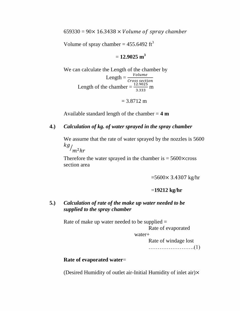
659330 = 90
Volume of spray chamber = 455.6492 ft3
= 12.9025 m3
We can calculate the Length of the chamber by
Length =
Length of the chamber =
m
= 3.8712 m
Available standard length of the chamber = 4 m
4.) Calculation of kg. of water sprayed in the spray chamber
We assume that the rate of water sprayed by the nozzles is 5600
⁄
Therefore the water sprayed in the chamber is = 5600 cross
section area
=5600 kg/hr
=19212 kg/hr
5.) Calculation of rate of the make up water needed to be
supplied to the spray chamber
Rate of make up water needed to be supplied =
Rate of evaporated
water+
Rate of windage lost
…………………….(1)
Rate of evaporated water=
(Desired Humidity of outlet air-Initial Humidity of inlet air)

Mass Flow rate of
air……………………………………………….(2)
Desired Outlet Humidity of air=
0.015
⁄
Inlet Humidity
Let the initial Humidity of air be Y1
We have inlet dry bulb temperature, TG= 35
Wet bulb temperature, Tw=22
We have from the Lewis relation,
TG- Tw=
(Saturated Humidity-Humidity)
At 35 latent heat of water is 2450 kj/kg of water
Specific heat of air is = (1.005+1.88 Y1) kj/k.kg of dry air
We have
TG- Tw=
(Saturated Humidity-Y1)
Saturated humidity
=
( )
Saturated vapour Pressure can be calculated from Antoine’s equation
=exp(11.96481-
)
=0.02572 bar
=2572 pa
Atmospheric pressure = 101325 pa
Saturated Humidity =
( )

=0.0162
⁄
The equation becomes
35-22=
(0.0162-Y1)
13 ( ) ( )
13.065+24.44
Y1 = 0.0108
⁄
Mass Flow rate of air
Mass flow rate of air =
Vol flow rate of air = 1000 m3/min
Humid vol of air at 35 can be calculated by using the equation
( ⁄
⁄ ) (
)
= 0.8875 m3/kg of dry air
Mass flow rate of air =
Kg of dry air/min
= 1126.8 Kg of dry air/min
= 67607 Kg of dry air/hr
from equation (2) we have
Rate of Evaporated water = (0.015-
0.0108)

=283.9494 Kg of water/hr
Rate of windage lost
We assume windage lost to be 0.2 %
Rate of windage lost = 0.002 kg. of water sprayed
= 0.002 19212
=38.424 Kg of water/hr
Blow down water:
Let the makeup water TDS be 300ppm and that it must not
exceed 900ppm.
r=C2/C1=3
B= ( )
=103.55
Taking the
From equation (1) we have
Rate of make-up water needed to be supplied =
Rate of windage lost +Rate of Evaporated water + Blow down
=(283.9494+38.424+103.55)
= 423.654Kg of water/hr
6.) Calculation of rate of the Re circulated water
Rate of re-circulated water =
Total water sprayed in the spray chamber – make up water
needed to be supplied
Rate of re-circulated water = (19212 –423.654) kg of water/hr
= 18788.346 kg of water/hr
7) Calculation of number of power required to operate the nozzle
This is given by
P = Vol. flow rate of water
( )
We take operating pressure as 1 atmospheric pressure
Now,
For vapour pressure of water we have antoine’s equation
Vapour Pressure of water at 20 (
)
= 5487.8 pa
Vol flow rate of water can be calculed
Lets take the density of water at 20 be equal to 1000 kg/m3
We have the mass flow rate of water = 19212 kg/hr
So the Volume flow rate of water =
=
= 19.212 m3/hr
= 0.0053 m3/sec
the power requirement to operate the nozzles is
= 0.0053 ( )Watt
= 776.4484 watt
= ⁄
= 1.0408 HP
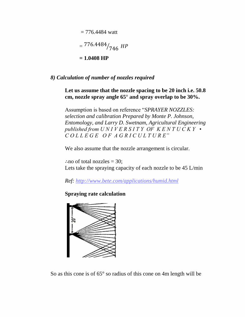
8) Calculation of number of nozzles required
Let us assume that the nozzle spacing to be 20 inch i.e. 50.8
cm, nozzle spray angle 65 and spray overlap to be 30%.
Assumption is based on reference “SPRAYER NOZZLES:
selection and calibration Prepared by Monte P. Johnson,
Entomology, and Larry D. Swetnam, Agricultural Engineering
published from U N I V E R S I T Y OF K E N T U C K Y •
C O L L E G E O F A G R I C U L T U R E”
We also assume that the nozzle arrangement is circular.
no of total nozzles = 30;
Lets take the spraying capacity of each nozzle to be 45 L/min
Ref: http://www.bete.com/applications/humid.html
Spraying rate calculation
So as this cone is of 65 so radius of this cone on 4m length will be

r = 4m (
)=2.55 m
area of water each nozzle will spray =
Now 30% overlap does equivalent area each nozzle spray =0.70
= 14.29
We have spray capacity = 45 L/min
= 2700 L/hr
For water its capacity = 2700 kg/hr
= 2700 kg/hr
⁄
=188.94 kg/hr.m2
no. of nozzles = 30
=5668 kg/hr.m2
Which satisfies our assumption of spraying rate.
Volume contribution of each Nozzle =
=
=
= 0.444 m3
no of nozzles = 30
Vol. contribution of each nozzle = 0.444 m3


b.) Mechanical Design
1.) Thickness of the spray chamber:
The diameter of the spray chamber is assumed to be 2 m.
This is owing to the fact that higher diameter puts difficulty in
saddle support. This is discussed in details in the support design
part
Maximum working pressure =1 bar;
Liquid height inside column = (Di) =2 m;
Pressure because of liquid inside the column = ρ*g*h =
1000*2.*10
= 20000 pa;
Design pressure = 1+ 0.2 =1.2 bar;
Consider, Joint efficiency j=0.85;
corrosion allowance c=3 mm
Shell material: IS: 2041-1962, 20 Mo55 (for non occurrence of corrosion)
Allowable stress,f=140 MPa;
We consider, ⁄ <0.25; for validity
So the formula to calculate the thickness simplifies to
t =
= 1.076 mm;
Considering corrosion factor thickness t= 1.076+3 = 4.076 mm;
Standard available thickness is 5mm
t0 =5 mm;
D0 = Di + 2*ts;
=2 + 0.01 = 2.01 m;
Standard outer diameter of spray chamber Do=2.1 m;
Inner diameter of spray chamber Di=2.09 m
⁄ = 5/2090 = 0.0023 < 0.25 Valid
2.) Head design: Conical head
Apex angle 2α =600
Allowable stress f= 140 MPa;
α = 300 (half apex)
Corrosion allowance c = 3 mm;
Surface area of conical head (A) = 1.57*D*√ ((D2/4) +h
2);
Volume capacity v= ⁄ * π*(D2/4)*h;
At junction of head and shell:
De = Outer diameter of the cone = outer diameter of shell = 2.1
m;
A factor Z is taking into account the influence of this
discontinuity stresses is therefore introduced into the basic thin-
shell equation to determine the thickness of the cone at the
junction or knuckle,
z = 1.35 for α =300
Thickness of shell:
t=
= 1.52 mm;
t+c=1.52 + 3 =4.52 mm;
Standard available thickness, is5 mm;
Away from the junction:
Thickness, t=
*
( );
d= 0.5*√
= 0.5*√
=0.055 m
=55 mm;
Di = 2 m = 2000 mm;
Dk=Di – d = 1.945 m;
t=1.21 mm;
thead= 5 mm;
Tan α=
l=
= 1.68 m;
Cos α =h/l;
h=
1.46 m;
thead = 5 mm;
l = 1.68 m; h=1.46 m;
3.) Support Design: Saddle support
ASME SA 283 grade C
f= 108 MPa;
θ =1500;
Ring stiffeners adjacent to saddle NA
Distance from tangent to saddle support = A
Tangent length l= 3.8m (4 m standard);
Thickness of shell ts=5 mm = th=0.005 m;
Inner diameter Di = 2 m; outer diameter D0= 2.1 m;
D= Blank diameter = 2.1 m;
B= bearing plate width = 0.5 m;

Density of shell material, ρshell material = 8000 kg/m3;
Weight of head whead = π/4*(D2*ts*ρhead*g)
=1357.045 N;
Weight of shell:
Wshell= π*(Di+ts)*ts *ρ*g*l= 9871.66 N;
Volume,V=1/3*(π*D2/4*h) =
( )
= 2.1 m
3;
Weight of liquid in head,
Wliquid in head = 2*v*ρ*g
=2*2.1*1000*9.8
=4.12*104 N;
Weight of liquid in shell:
Wliquid in shell = π/4*Di2*l*ρ*g
= 9.85*105 N;
Wtotal = 1.037 MN;
W1= wt/2 = 0.52 MN;
h=
=
( )
= 1.82 m;
R=Di/2 = 1 m;
A=R/2 = 0.5 m;
At supports:
M2 = -w1 *A*{1-
}
=-0.26*(1-
) = -0.133 MN;
Longitudinal bending stress at saddles
D/2
α h
f2 =
-
( )
t/r=0.005; k1=1; K2=1;
f2 = 12.8+8.47 = 21.27 MN/m2;
f21=
+
( ) = 12.8-8.47=4.33 MN/m
2;
(σt)max = f*j= 91.8 MN/m2;
(σc)max =
= ( )
= 62.5 MN/m
2;
f2< (σt) max; f21< (σt) max; Verified
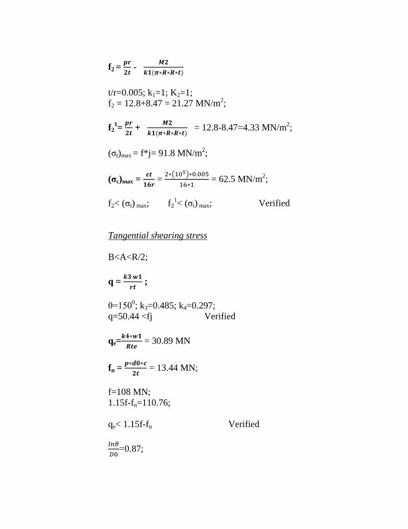
Tangential shearing stress
B<A<R/2;
q =
;
θ=1500; k3=0.485; k4=0.297;
q=50.44 <fj Verified
qe=
= 30.89 MN
fn =
= 13.44 MN;
f=108 MN;
1.15f-fn=110.76;
qe< 1.15f-fn Verified
=0.87;

=0.0024 (t/Do < .0025) Hence, valid.
Circumferential Stress:
For a shell wet stiffened by rings:
f3=
( ) ;
k5= 0.675;
B=0.5 m;
f3 = 125.64 MPa< 135(1.25f) Verified
l/R = 6<8; k6= 0.007; A/R=0.5;
f4 =
( ) -
( ) = -47.27-436.8 = -484.1
B=0.5 m>0.05 m;
K9=0.260; tc = 0.005 m;
f5 =
( ( ( ) ))
=
=44.31 MN <72 MN (2/3 f) Verified
4.) Nozzle in shell for water outlet:
tnozzle=0.016 m;
A= (d+2c)*tr
p= 1.209 bar
j=0.85
D0=2.1 m
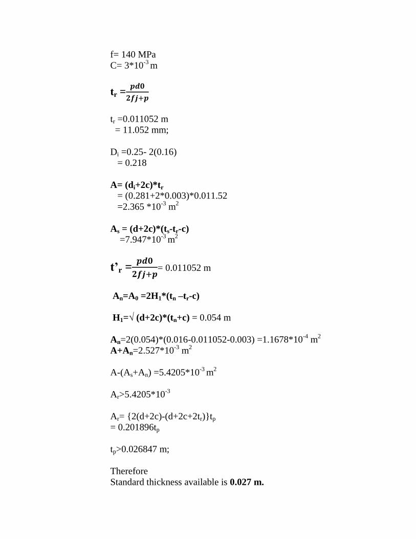
f= 140 MPa
C= 3*10-3
m
tr =
tr =0.011052 m
= 11.052 mm;
Di =0.25- 2(0.16)
= 0.218
A= (di+2c)*tr
= (0.281+2*0.003)*0.011.52
=2.365 *10-3
m2
As = (d+2c)*(ts-tr-c)
=7.947*10-3
m2
t’r =
= 0.011052 m
An=A0 =2H1*(tn –tr-c)
H1=√ (d+2c)*(tn+c) = 0.054 m
An=2(0.054)*(0.016-0.011052-0.003) =1.1678*10-4
m2
A+An=2.527*10-3
m2
A-(As+An) =5.4205*10-3
m2
Ar>5.4205*10-3
Ar= {2(d+2c)-(d+2c+2tr)}tp
= 0.201896tp
tp>0.026847 m;
Therefore
Standard thickness available is 0.027 m.
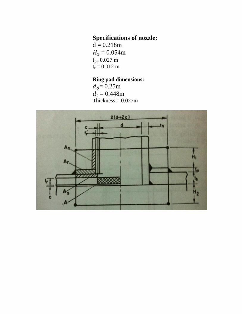
Specifications of nozzle:
d = 0.218m
= 0.054m
tp= 0.027 m
tr = 0.012 m
Ring pad dimensions:
= 0.25m
= 0.448m Thickness = 0.027m

Mechanical Design specifications:
Shell: IS: 2041-1962; 20 Mo55 C steel
tshell= 5 mm;
Di = 2 m;
D0 = 2.1 m;
L= 4 m;
Conical head: IS: 2041-1962; 20 Mo55 C steel:
thead = 5 mm;
H =1.82 m;
D = 2.1 m;
Saddle support: C steel (ASME SA 283 grade C):
θ = 150
0;
f = 108 MPa;
l =4 m:
B =0.5 m;
D = 2.1 m;
R = 1 m;
A = 0.5 m;
Specifications of nozzle for water outlet:
d = 0.218m
= 0.054m
tp= 0.027 m
tr = 0.012 m
Ring pad dimensions:
= 0.25m
= 0.448m Thickness = 0.027m

5.) Design of Tank
We will go for circular water tank made of concrete
Total volume of water = V;
Air velocity u= 5.3 m/s;
Water sprayed per hour = 31640 kg/hr
= 1318.33 kg/day
= 1318.33/ρwater
=1.318 m3/day
Volume of water = 2*1.318
Π*D2/4 *h=2.64
If D=H then H=1.5 m = D;
Thickness of wall: t= (30H+50) = 95 mm
Therefore, t=150 mm (as a minimum of 150mm thickness is required)
H/t = 10; H/D= 1;
f = 0.012; k =0.37;
Maximum bending moment at base = fwH3;
W= weight of water in KN/m3
=ρ*g =9800 kg/m2s
W= 9.8 KN/m3;
Maximum bending moment at base =0.3969 KN
Max circumferential/hoop tension
T= w/2*HD(1-k)
= 6.95 KN/m
Position of maximum circumferential tension
h=KH = 0.56 m;
Circular advantages:
Lesser amount of material
Economical up to 2,000,000 l
D= (5-8) m; H= (3-4) m;
Volume of tank V= 2.64 m3
for D=5 m and H= 3 m
Thickness t= (30H+50) =160 mm;
H/t = 18.75; H/D = 0.6;
F=0.012/0.006; k=0.37/0.28;
Maximum bending moment BM max = 3.175 KN
Maximum hoop tension (HT) max = 46.31 KN/m
Position of maximum circumferential stress h= KH = 1.11 m
Circular tanks with flexible joints at the base:
Walls are subjected to hydrostatic pressure
Tank wall is designed as thin cylinder
At base P = WH;
Hoop tension = WHD/2;
W= ρwater = 1000 kg/m3;
H=depth of water = 3 m;
D= diameter of the tank = 5 m;
Steel area required at base for 1 m height =
cm
2 = 7.5 cm
2
We provide 16 mm of bars at 7 cm centers
At= 28.73 cm2; m=13;
Use mix m200 concrete of allowable stress in tension = 12 kg/cm2
Tensile stress =
( )
12=
( )
t= 2.8 cm = 28 mm;
Here reinforcements will be provided on both faces 16 mm bars at 14 cm
centers are provided on each face.
Vertical reinforcement = (0.3-(0.1*(28-10)/35));
=0.25%
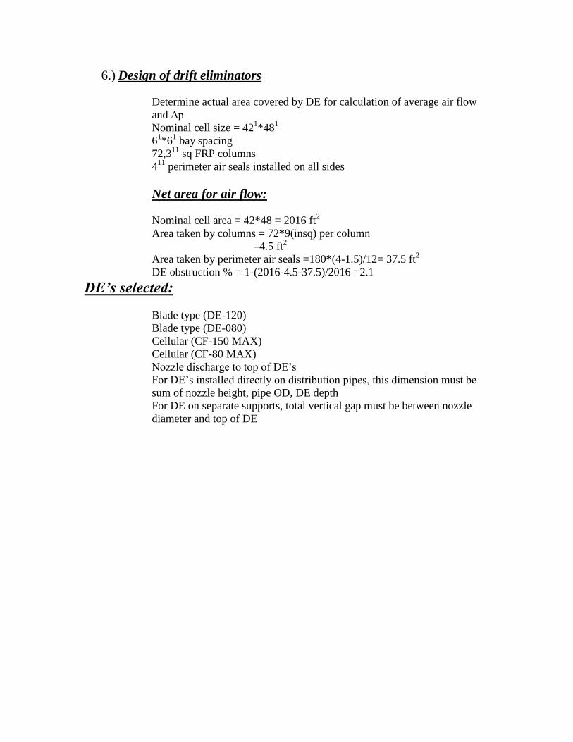
6.) Design of drift eliminators
Determine actual area covered by DE for calculation of average air flow
and Δp
Nominal cell size = 421*48
1
61*6
1 bay spacing
72,311
sq FRP columns
411
perimeter air seals installed on all sides
Net area for air flow:
Nominal cell area = 42*48 = 2016 ft2
Area taken by columns = 72*9(insq) per column
=4.5 ft2
Area taken by perimeter air seals =180*(4-1.5)/12= 37.5 ft2
DE obstruction % = 1-(2016-4.5-37.5)/2016 =2.1
DE’s selected:
Blade type (DE-120)
Blade type (DE-080)
Cellular (CF-150 MAX)
Cellular (CF-80 MAX)
Nozzle discharge to top of DE’s
For DE’s installed directly on distribution pipes, this dimension must be
sum of nozzle height, pipe OD, DE depth
For DE on separate supports, total vertical gap must be between nozzle
diameter and top of DE
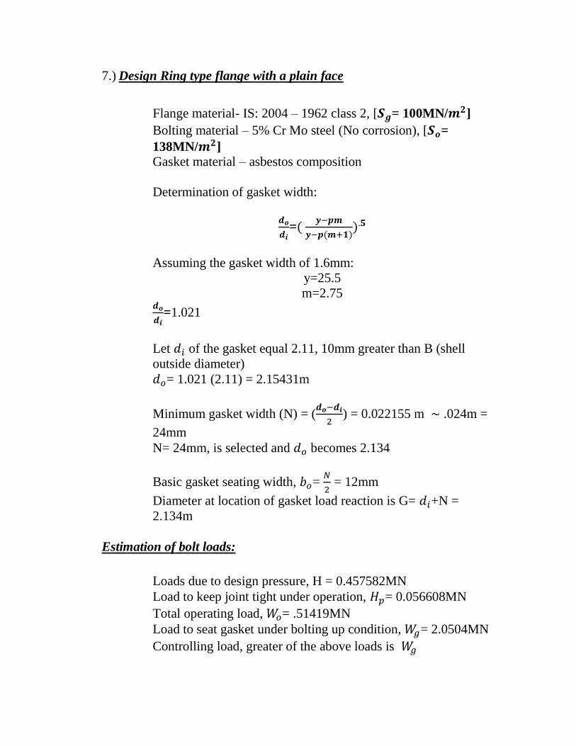
7.) Design Ring type flange with a plain face
Flange material- IS: 2004 – 1962 class 2, [ = 100MN/ ]
Bolting material – 5% Cr Mo steel (No corrosion), [ =
138MN/ ]
Gasket material – asbestos composition
Determination of gasket width:
=(
( ))
Assuming the gasket width of 1.6mm:
y=25.5
m=2.75
=1.021
Let of the gasket equal 2.11, 10mm greater than B (shell
outside diameter)
= 1.021 (2.11) = 2.15431m
Minimum gasket width (N) = (
) = 0.022155 m .024m =
24mm
N= 24mm, is selected and becomes 2.134
Basic gasket seating width, =
= 12mm
Diameter at location of gasket load reaction is G= +N =
2.134m
Estimation of bolt loads:
Loads due to design pressure, H = 0.457582MN
Load to keep joint tight under operation, = 0.056608MN
Total operating load, = .51419MN
Load to seat gasket under bolting up condition, = 2.0504MN
Controlling load, greater of the above loads is
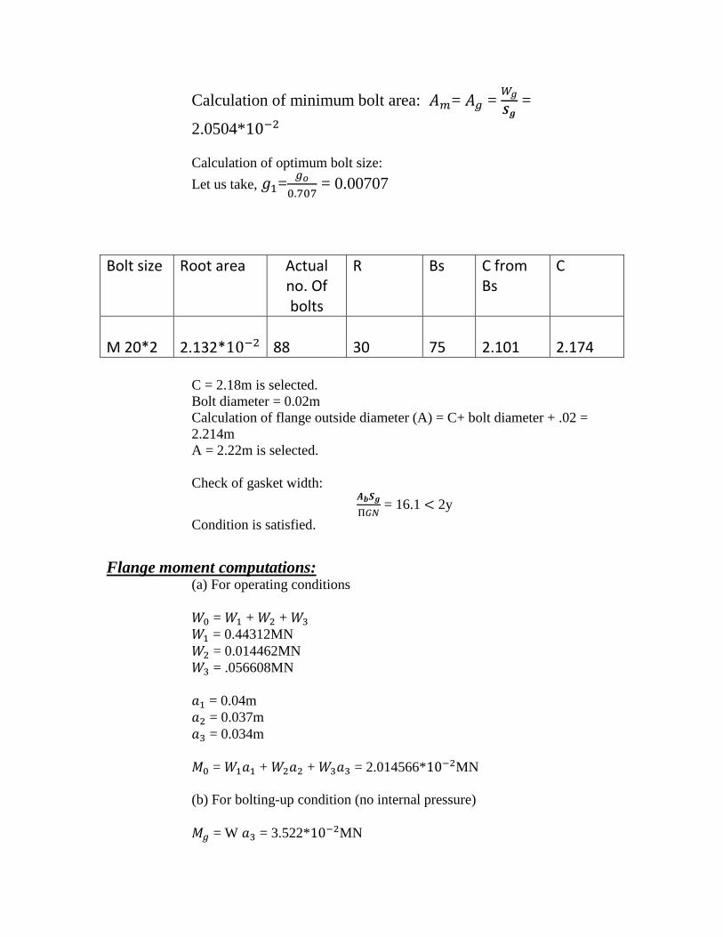
Calculation of minimum bolt area: = =
=
2.0504*
Calculation of optimum bolt size:
Let us take, =
= 0.00707
Bolt size Root area Actual no. Of bolts
R Bs C from Bs
C
M 20*2
2.132*
88
30
75
2.101
2.174
C = 2.18m is selected.
Bolt diameter = 0.02m
Calculation of flange outside diameter (A) = C+ bolt diameter + .02 =
2.214m
A = 2.22m is selected.
Check of gasket width:
= 16.1 2y
Condition is satisfied.
Flange moment computations:
(a) For operating conditions
= + +
= 0.44312MN
= 0.014462MN
= .056608MN
= 0.04m
= 0.037m
= 0.034m
= + + = 2.014566* MN
(b) For bolting-up condition (no internal pressure)
= W = 3.522* MN

Controlling moment: =
=
=
K=
=
= 1.0162 (from graph)
Y = 90MN
t =√
= .10458m (assuming =1)
Actual bolt spacing ( ) = 0.0778m
= (
) = 0.7528
= *t = .7528*.10458
t = .07768m
Available standard thickness is 80mm of the flange.
Specifications of the flange between the head
and shell:
Thickness: 80mm Actual bolt spacing ( ) = 0.0778m
No. of bolts = 88
Bolt size = M 20*2
Bolt dia. = 0.02m
= 2.134m
= 2.11m

8)TORNADO WATER FILTER
The key is the combination of an Entrance Nozzle Plate, Velocity Tube, High
Velocities down the Length of the Filter Screen and Reduced Flow Velocity
through the Tornado Filter Screen. The Entrance Nozzleplate increases the
velocity of water entering the filter and forces it in a downward, rotational pattern.
The Velocity Tube keeps the water moving at an optimal velocity down the entire
length of the filter screen. The Filter Screen itself has been designed to have a
maximum flow velocity through the screen of 0.50 feet per second (1.50 Gallons
per square inch per minute) or less. The low velocity of the water passing through
the screen allows the high cleaning velocity of the water entering the Tornado
Filter to force sand and debris off the screen and into the End Cap (Catch Basin).
From the End Cap, sand and debris are washed out through the flush valve while
your clean water exits through the Filter Screen and into your water supply line.
Proper installation and Filter setup will in a 5-8 psi differential on Surface Water
conditions
Specifications:
Tornado Filters are constructed from 304/304L Stainless Steel Pipe
meeting ASTM A778 specifications
Mesh Screen Material is 316 Stainless Steel
Surface Water Tornado Filters are offered with 24 or 40 mesh screens only
150 psi Pressure Rating
Minimum Operating Pressure 15 PSI
9)AIR FILTER
Flow Rate
(cfm) A B C D W
48,000 120” 80” 60” 72” 30”
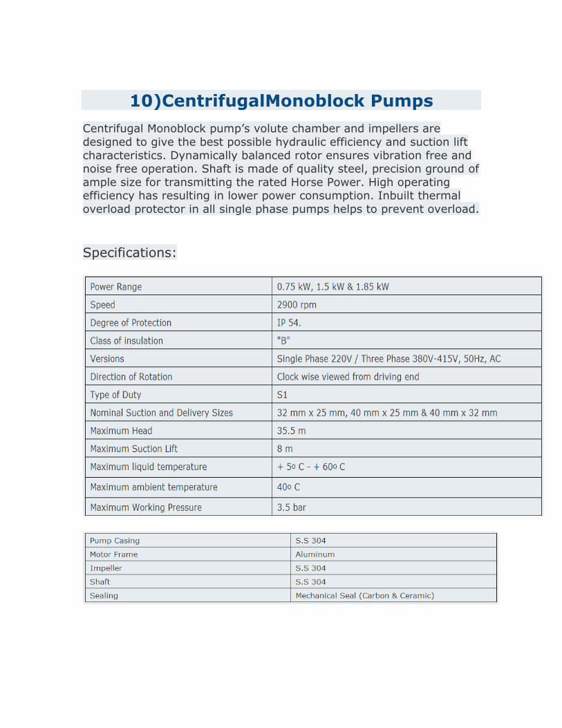
10)CentrifugalMonoblock Pumps
Centrifugal Monoblock pump’s volute chamber and impellers are
designed to give the best possible hydraulic efficiency and suction lift
characteristics. Dynamically balanced rotor ensures vibration free and noise free operation. Shaft is made of quality steel, precision ground of
ample size for transmitting the rated Horse Power. High operating efficiency has resulting in lower power consumption. Inbuilt thermal
overload protector in all single phase pumps helps to prevent overload.
Specifications:

11)BLOWERS:
Centrifugal Air Blower
A complete range of standard Air Blowers is available for flow rates from 25 cu. mt./hr through 10,000 cu. mt./hr in single stage and upto any capacity in parallel configuration for working pressure range upto 1kg/sq. cm.
Twin Lobes Blowers
Twin lobe roots blower is available with low RPM high pressure , high RPM low pressure and compressors .
Performs very well in single stage as well as in double stage.
Available in all shapes and sizes from 3 inches C.D. to 22 inches. Body length may vary from 1.5 inches to 66 inches.
Available in air cooled as well as water cooled variant.
The compact, sturdy design is engineered for continuous service when operated in accordance with speed and pressure rating.
Flow rate
: From 60m3/hr to 57,117m3/hr
Pressure : Up to 1kg/cm2 with single stage
Up to 2kg/cm2 with double stage
Vacuum : Up to 0.5kg/cm2

c)Cost calculation:
Weight of shell, Wshell= π*(Di+ts)*ts *ρ*l = 987.166 kg Weight of head, whead = π/4*(D
2*ts*ρhead) = 135.7045 kg
The material cost of the shell and head are 1000$/ ton, i.e. Rs600/kg on an
average.
Total capital to be invested to make a humidifier = cost/kg * total weight
=Rs 6,73,722
d)Power consumption in a year:
Power consumed by the motor is
Price of power is Rs 3.41/kwh as of now. Total no. of hours in 1 year = 8760 hrs
Total power consumed =776.4484 watt*8760
= 6801.688 kwh Cost of power consumption by the pump in a year = 6801.688*3.41 = Rs23,193.76

e) Back Calculation for checking the overdesign:
We have,
Standard nominal diameter=2.1m
So,Inner diameter of shell,D=2.1-2(0.005)=2.09m
Cross sectional area,A=3.43m2
Standard Length of chamber=4m
So,Volume of chamber=A*L=13.72m2
Hence,we get ,
Sensible heat lost by air,Q=h*V*LMTD=714462.80 BTU/hr
Again,we have
Specific heat of inlet air,Cv1=0.244 BTU/lbF
Enthalpy of inlet air, H1=2299400BTU/hr
Specific heat of outlet air, Cv2=0.24+0.45*Y2
Enthalpy of outlet air, H2=Cv2*(outlet air temp-reference temp)*mass
flow rate of air
=Cv2*(77-32)*m
=45*Cv2*m
Since, Q=H1-H2
We get, H2=H1-Q=1584937.2BTU/hr
I.e. m*Cv2*45=1584937.2
m*Cv2=35220.8267BTU/hrF
Now,
Mass flow rate ,m=(1000/sp volume) kg/min
=(1000*60)*273/((0.056Y2+0.0345)*22.4*(25+273))
=2453.859/(0.056Y2+0.0345) kg/hr
=5410.759/(0.056Y2+0.0345)lb/hr
Thus,
m*Cv2=5410.759*(0.24+0.45Y2)/(0.056Y2+0.0345)=35220.8267BT
U/hrF
(0.24+0.45Y2)=6.509*(0.056Y2+.0345)
Y2=(0.2413-0.24)/(0.45-0.365)
=0.01529
Thus, we get outlet humidity to be around 0.01529 which is as per our
desired value. Hence, we can conclude that our above design
specifications are appropriate.

e) GUI using MATLAB based functions:

References:
http://www.kayblowers.com/twinlobe.htm http://www.everestblowers.com/air-blowers.htm http://www.morrillinc.com/specs/Tornado_Specifications_R2_2012.pdf Chemical Equipment Design, B.C.Bhattacharya Mass Transfer Operations, B.K.Dutta