spring-applied brake bfk457 - intorq · spring-applied brake bfk457 compact and easily fitted 0.12...
TRANSCRIPT
www.intorq.com
setting the standard
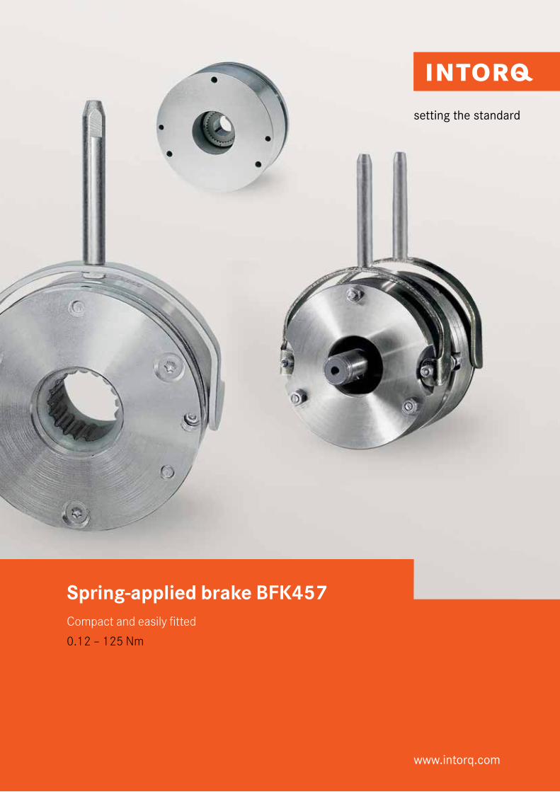
Spring-applied brake BFK457Compact and easily fitted
0.12 – 125 Nm
The INTORQ brand stands for reliable brake solutions with the highest product standards. INTORQ products are used in a very diverse range of applications, from brake motors and industrial trucks to hoists, cranes and wind turbines. We can create the right solution for you and your drive – individually and reliably.
The INTORQ module system offers numerous variants that can be used in many motors and geared motors, setting standards worldwide. We have been increasing our international presence step by step, establishing sites in Shanghai, Atlanta and Pune. So our network of sales and service staff is close at hand all over the world, ready to support you.
We set the standards
INTORQ at a glance
❙ Electromagnetic brakes and clutches ❙ Flexibility with standard options as well as
customised solutions❙ Centralised product development and
production located in aerzen❙ Fast response and delivery times globally
thanks to production and warehousing in Shanghai, Atlanta and Pune.
❙ Over 50 million euros a year sales volume❙ 800,000 units a year ❙ 13,000 square metres production area❙ 250 employees❙ Market leader with 63 sales partners in 49
countries
INTORQ I Spring-applied brake INTORQ BFK457
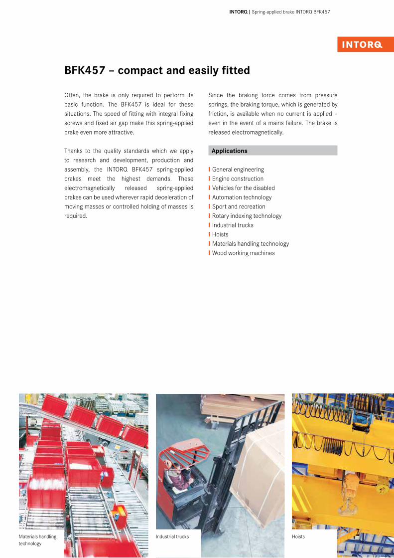
Often, the brake is only required to perform its basic function. The BFK457 is ideal for these situations. The speed of fitting with integral fixing screws and fixed air gap make this spring-applied brake even more attractive.
Thanks to the quality standards which we apply to research and development, production and assembly, the INTORQ BFK457 spring-applied brakes meet the highest demands. These electromagnetically released spring-applied brakes can be used wherever rapid deceleration of moving masses or controlled holding of masses is required.
Since the braking force comes from pressure springs, the braking torque, which is generated by friction, is available when no current is applied – even in the event of a mains failure. The brake is released electromagnetically.
Applications
❙General engineering❙Engine construction❙Vehicles for the disabled❙Automation technology❙Sport and recreation❙Rotary indexing technology❙Industrial trucks❙Hoists❙Materials handling technology❙Wood working machines
BFK457 – compact and easily fitted
Industrial trucks HoistsMaterials handling technology
4I5 INTORQ I Spring-applied brake INTORQ BFK457
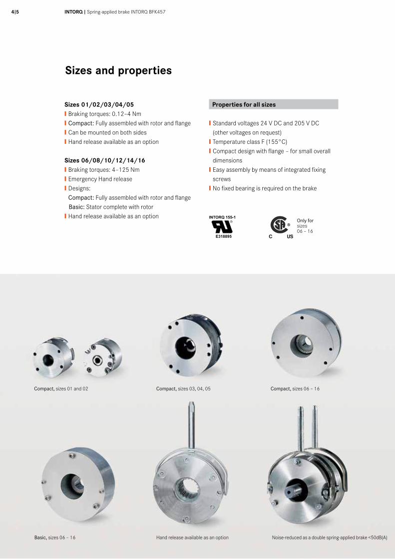
Sizes and properties
Sizes 01/02/03/04/05❙ Braking torques: 0.12–4 Nm❙ Compact: Fully assembled with rotor and flange❙ Can be mounted on both sides❙ Hand release available as an option
Sizes 06/08/10/12/14/16❙ Braking torques: 4–125 Nm❙ Emergency Hand release❙ Designs:
Compact: Fully assembled with rotor and flange Basic: Stator complete with rotor❙ Hand release available as an option
Properties for all sizes
❙ Standard voltages 24 V DC and 205 V DC (other voltages on request)❙ Temperature class F (155°C)❙ Compact design with flange – for small overall dimensions❙ Easy assembly by means of integrated fixing screws❙ No fixed bearing is required on the brake
Basic, sizes 06 – 16 Noise-reduced as a double spring-applied brake <50dB(A)
Compact, sizes 06 – 16Compact, sizes 03, 04, 05
Hand release available as an option
Compact, sizes 01 and 02
INTORQ 155-1
E318895
Only for sizes06 – 16
Contents
Product information ............................................4
List of abbreviations ...........................................5
Technical data
Sizes 01 and 02 ....................................................6
Sizes 03 – 05 ........................................................7
Sizes 06 – 16 Compact .........................................8
Sizes 06 – 16 Basic .............................................10
Sizes 06 – 16 low-noise design ............................12
Overview ............................................................14
List of abbreviations
PN [W] Rated coil power at rated voltage and 20°CUN [V DC] Rated coil voltageMK [Nm] Rated torque of the brake at a relative speed of 100 r/minMdyn [Nm] dynamic brake torque, measured at constant speed of rotationML [Nm] Load torque, torque that the static load produces at the motor shaft∆n0 [r/min] Initial relative speed of the brakeJL [kgm2] moment of inertia of the load, referred to referred to the output shaft (load shaft)Q [J] Heat/energyQE [J] Maximum permissible friction work per switching cycle, thermal rating of the brakeQsmax [J] maximum permissible friction work during cyclic switching, depending on the operating frequencySh [1/h] Operating frequency, the number of repeated operations per unit time
Shue [1/h] transitional operating frequency, thermal rating of the brake/clutchShmax [1/h] Maximum permissible operating frequency, depending on the friction work per operationsLN [mm] Rated air gapsHL [mm] Hand-release air gap, setting dimension of hand-releaset1 [s] Engagement time, the total of the reaction delay and torque rise time t1 = t11 + t12t2 [s] Disengagement time, time from switching the stator until the torque has reduced to 0.1 MKt3 [s] Slipping time to standstill (after t11)t11 [s] Delay time when connecting,
time from disconnecting the voltage until the torque begins to riset12 [s] Rise time of braking torque, time from
beginning of rise of torque until braking torque is reached
A-A
A-A
Größe MK MKmax P20° dH7d1 d2 d3 d4 da di h l SLN
2) SL max bei MK SL max bei Mkmax m01 0,12 0,24 5,0 5 1) / 6 1) 2x M2,5 32 13,5 37 25 18 31,3 9 0,1 +0,08 / -0,05 0,35 0,23 0,202 0,25 0,50 6,6 6 1) / 7 1) / 8 1) 2x M3 40 16 47 32 21 31 12 0,1 +0,08 / -0,05 0,35 0,23 0,2503 0,50 1,00 9,0 6 / 7 / 8 / 9 / 10 3x M3 48 19 56 38,5 30 31,8 15 0,15 ±0,1 0,4 0,3 0,404 1,00 2,00 11,5 6 / 7 / 8 / 10 3x M3 58 24 65 47,5 35 33,8 15 0,15 ±0,1 0,4 0,3 0,5505 2,00 4,00 13,0 8 / 10 / 11 / 12 / 15 3x M4 66 28 75 55 40 35,9 15 0,15 ±0,1 0,4 0,3 0,8
• Spannungen: 24 V, 103 V , 205 V• MK: Kennmoment der Bremse in Nm, bezogen auf ∆n = 100 r/min Achtung: Bremsmoment ist drehzahlabhängig• P20°: Leistung der Spule bei 20°C in Watt• Standardpassfedernut nach DIN 6885/1-P9• Länge der Anschlussleitung 400 mm• alle Maße in mm• Änderungen vorbehalten
• 1) ohne Nut• 2) Minimaler Luftspalt, tatsächlicher Wert ergibt sich aus den Summentoleranzen der Einzelteile
5020
1030
40m
m0
Schu
tzve
rmer
k IS
O 1
6016
bea
chte
n. C
opyr
ight
rese
rved
.
1 2 3 4 5 6 7 8 9 10 11 12
A
B
C
D
E
F
G
H
1 2 3 4 5 6 7 8 9 10 11 12
A
B
C
D
E
F
G
H
A
A
A
A
Ind./ Anz./ind. quan.
Änder-Nr./revision no.
Datum/date
Name/name
Datum/date Name/name
Bea/drn
Gepr/chkd
Norm/appr
Datei/file
Benennung/name of drawing
Zeichnungsnummer/drawing no.
Ersatz fuer/back-up for
Blatt/sheetCAD
M14.0284_BFK457-05.iami
StrateLogermann
08.02.201308.02.2013
Maßblatt Federkraftbremse BFK457Baugröße 01 / 02 / 03 / 04 / 05
M14.0284Zeichnung M14.0284-D vom 02.04.2003
12
3 - xxxxxx 08.02.2013 STR
40°
30°
2x180°
120°3x
2x180°
45°
120°3x
120°3x
40°
3x120°
d3d4
SLN
d2l
d1
d2d1
d3d4
h
h
SLN
l d d2 d2d1d1
dadidadi
d
6I7 INTORQ I Spring-applied brake INTORQ BFK457
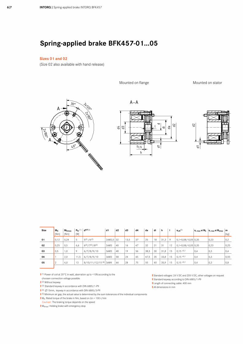
Spring-applied brake BFK457-01...05
❙ (1) Power of coil at 20°C in watt, aberration up to +10% according to the
choosen connection voltage possible
❙ (2) Without keyway
❙ (3) Standard keyway in accordance with DIN 6885/1-P9
❙ (4) n15mm, keyway in accordance with DIN 6885/3-P9
❙ (5) Minimum air gap, the actual value is determined by the sum tolerances of the individual components
❙ MK: Rated torque of the brake in Nm, based on ∆n = 100 r/min
Caution!: The braking torque depends on the speed
❙ MKmax: Holding brake with emergency stop
❙ Standard voltages: 24 V DC and 205 V DC, other voltages on request
❙ Standard keyway according to DIN 6885/1-P9
❙ Length of connecting cable: 400 mm
❙ All dimensions in mm
Sizes 01 and 02(Size 02 also available with hand release)
Mounted on flange Mounted on stator
Size MK MKmax PN (1) dH7(3) d1 d2 d3 d4 da di h l sLN(5) sL max at Mk sL max at Mkmax m [Nm] [Nm] [W] [kg]
01 0,12 0,24 5 5(2) /6(2) 2xM2,5 32 13,5 37 25 18 31,3 9 0,1+0,08/-0,05 0,35 0,23 0,2
02 0,25 0,5 6,6 6(2)/7(2)/8(2) 2xM3 40 16 47 32 21 31 12 0,1+0,08/-0,05 0,35 0,23 0,25
03 0,5 1,0 9 6/7/8/9/10 3xM3 48 19 56 38,5 30 31,8 15 0,15 ±0,1 0,4 0,3 0,4
04 1 2,0 11,5 6/7/8/9/10 3xM3 58 24 65 47,5 35 33,8 15 0,15 ±0,1 0,4 0,3 0,55
05 2 4,0 13 8/10/11/12/15 (4) 3xM4 66 28 75 55 40 35,9 15 0,15 ±0,1 0,4 0,3 0,8
sLN
A-A
A-A
Größe MK MKmax P20° dH7d1 d2 d3 d4 da di h l SLN
2) SL max bei MK SL max bei Mkmax m01 0,12 0,24 5,0 5 1) / 6 1) 2x M2,5 32 13,5 37 25 18 31,3 9 0,1 +0,08 / -0,05 0,35 0,23 0,202 0,25 0,50 6,6 6 1) / 7 1) / 8 1) 2x M3 40 16 47 32 21 31 12 0,1 +0,08 / -0,05 0,35 0,23 0,2503 0,50 1,00 9,0 6 / 7 / 8 / 9 / 10 3x M3 48 19 56 38,5 30 31,8 15 0,15 ±0,1 0,4 0,3 0,404 1,00 2,00 11,5 6 / 7 / 8 / 10 3x M3 58 24 65 47,5 35 33,8 15 0,15 ±0,1 0,4 0,3 0,5505 2,00 4,00 13,0 8 / 10 / 11 / 12 / 15 3x M4 66 28 75 55 40 35,9 15 0,15 ±0,1 0,4 0,3 0,8
• Spannungen: 24 V, 103 V , 205 V• MK: Kennmoment der Bremse in Nm, bezogen auf ∆n = 100 r/min Achtung: Bremsmoment ist drehzahlabhängig• P20°: Leistung der Spule bei 20°C in Watt• Standardpassfedernut nach DIN 6885/1-P9• Länge der Anschlussleitung 400 mm• alle Maße in mm• Änderungen vorbehalten
• 1) ohne Nut• 2) Minimaler Luftspalt, tatsächlicher Wert ergibt sich aus den Summentoleranzen der Einzelteile
5020
1030
40m
m0
Schu
tzve
rmer
k IS
O 1
6016
bea
chte
n. C
opyr
ight
rese
rved
.
1 2 3 4 5 6 7 8 9 10 11 12
A
B
C
D
E
F
G
H
1 2 3 4 5 6 7 8 9 10 11 12
A
B
C
D
E
F
G
H
A
A
A
A
Ind./ Anz./ind. quan.
Änder-Nr./revision no.
Datum/date
Name/name
Datum/date Name/name
Bea/drn
Gepr/chkd
Norm/appr
Datei/file
Benennung/name of drawing
Zeichnungsnummer/drawing no.
Ersatz fuer/back-up for
Blatt/sheetCAD
M14.0284_BFK457-05.iami
StrateLogermann
08.02.201308.02.2013
Maßblatt Federkraftbremse BFK457Baugröße 01 / 02 / 03 / 04 / 05
M14.0284Zeichnung M14.0284-D vom 02.04.2003
12
3 - xxxxxx 08.02.2013 STR
40°
30°
2x180°
120°3x
2x180°
45°
120°3x
120°3x
40°
3x120°
d3d4
SLN
d2l
d1
d2d1
d3d4
h
h
SLN
l d d2 d2d1d1
dadidadi
d
A-A
A-A
Größe MK MKmax P20° dH7d1 d2 d3 d4 da di h l SLN
2) SL max bei MK SL max bei Mkmax m01 0,12 0,24 5,0 5 1) / 6 1) 2x M2,5 32 13,5 37 25 18 31,3 9 0,1 +0,08 / -0,05 0,35 0,23 0,202 0,25 0,50 6,6 6 1) / 7 1) / 8 1) 2x M3 40 16 47 32 21 31 12 0,1 +0,08 / -0,05 0,35 0,23 0,2503 0,50 1,00 9,0 6 / 7 / 8 / 9 / 10 3x M3 48 19 56 38,5 30 31,8 15 0,15 ±0,1 0,4 0,3 0,404 1,00 2,00 11,5 6 / 7 / 8 / 10 3x M3 58 24 65 47,5 35 33,8 15 0,15 ±0,1 0,4 0,3 0,5505 2,00 4,00 13,0 8 / 10 / 11 / 12 / 15 3x M4 66 28 75 55 40 35,9 15 0,15 ±0,1 0,4 0,3 0,8
• Spannungen: 24 V, 103 V , 205 V• MK: Kennmoment der Bremse in Nm, bezogen auf ∆n = 100 r/min Achtung: Bremsmoment ist drehzahlabhängig• P20°: Leistung der Spule bei 20°C in Watt• Standardpassfedernut nach DIN 6885/1-P9• Länge der Anschlussleitung 400 mm• alle Maße in mm• Änderungen vorbehalten
• 1) ohne Nut• 2) Minimaler Luftspalt, tatsächlicher Wert ergibt sich aus den Summentoleranzen der Einzelteile
5020
1030
40m
m0
Schu
tzve
rmer
k IS
O 1
6016
bea
chte
n. C
opyr
ight
rese
rved
.
1 2 3 4 5 6 7 8 9 10 11 12
A
B
C
D
E
F
G
H
1 2 3 4 5 6 7 8 9 10 11 12
A
B
C
D
E
F
G
H
A
A
A
A
Ind./ Anz./ind. quan.
Änder-Nr./revision no.
Datum/date
Name/name
Datum/date Name/name
Bea/drn
Gepr/chkd
Norm/appr
Datei/file
Benennung/name of drawing
Zeichnungsnummer/drawing no.
Ersatz fuer/back-up for
Blatt/sheetCAD
M14.0284_BFK457-05.iami
StrateLogermann
08.02.201308.02.2013
Maßblatt Federkraftbremse BFK457Baugröße 01 / 02 / 03 / 04 / 05
M14.0284Zeichnung M14.0284-D vom 02.04.2003
12
3 - xxxxxx 08.02.2013 STR
40°
30°
2x180°
120°3x
2x180°
45°
120°3x
120°3x
40°
3x120°
d3d4
SLN
d2l
d1
d2d1
d3d4
h
h
SLN
l d d2 d2d1d1
dadidadi
d
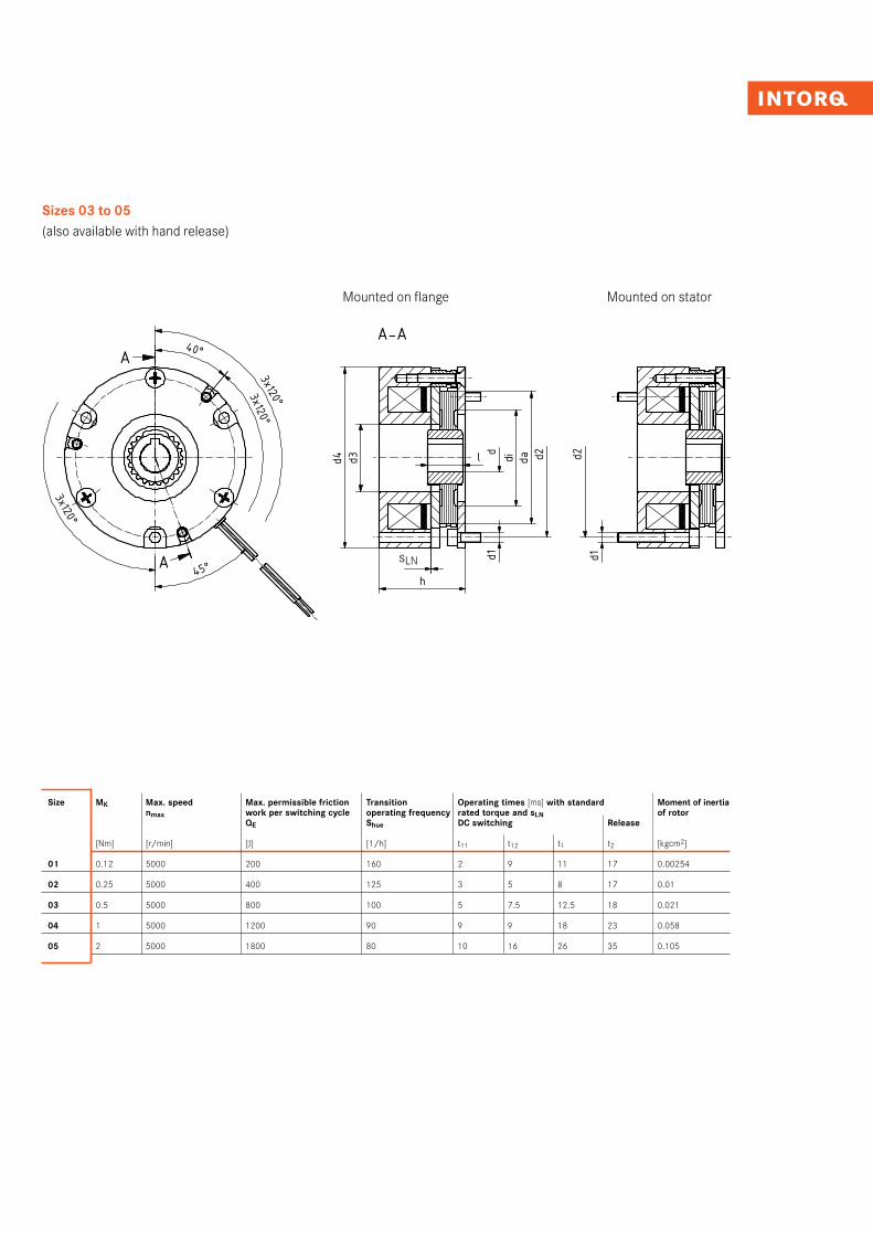
Mounted on flange Mounted on stator
Size MK Max. speed Max. permissible friction Transition Operating times [ms] with standard Moment of inertia nmax work per switching cycle operating frequency rated torque and sLN of rotor QE Shue DC switching Release
[Nm] [r/min] [J] [1/h] t11 t12 t1 t2 [kgcm2]
01 0.12 5000 200 160 2 9 11 17 0.00254
02 0.25 5000 400 125 3 5 8 17 0.01
03 0.5 5000 800 100 5 7.5 12.5 18 0.021
04 1 5000 1200 90 9 9 18 23 0.058
05 2 5000 1800 80 10 16 26 35 0.105
❙ Standard voltages: 24 V DC and 205 V DC, other voltages on request
❙ Standard keyway according to DIN 6885/1-P9
❙ Length of connecting cable: 400 mm
❙ All dimensions in mm
Sizes 03 to 05(also available with hand release)
sLN
8I9 INTORQ I Spring-applied brake INTORQ BFK457
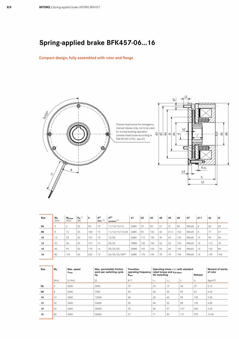
Spring-applied brake BFK457-06...16
Größe MK MKmax P20° b d J7 vorg. 1) d H7 Standard 2) d1 d2 d3 d4 d5 d6 d7 d11 da di h h1 h2 h3 h4 h5 h6 h7 l l1 l2 3) SLN ±0,1 SLmax bei MK SLmax bei MKmax a a a a β β β β m
06 4 6 20 90 10 11 / 12 / 14 / 15 3xM4 72 84 31 31 84 M4x30 8 60 40 41,3 45,3 7 6 15,8 107 49 49,7 18 400 6 0,2 0,6 0,4 25° 10° 1,108 8 12 25 108 10 11 / 12 / 14 / 15 / 20 3xM5 90 102 42 41,5 102 M5x35 8 77 57 49,8 54,8 8,5 7 16,3 118 59 57,1 20 400 9 0,2 0,6 0,45 25° 10° 1,910 16 23 30 137 10 15 / 20 3xM6 112 130 44 44 130 M5x40 10 95 66 56,4 61,5 10 8 27,4 142 74 65,2 20 400 12 0,3 0,7 0,5 25° 10° 3,812 32 46 40 157 14 20 / 25 3xM6 132 150 52 52 150 M5x45 10 115 70 62,4 67,4 10 8 29,4 162 84 71,2 25 400 12 0,3 0,8 0,5 25° 10° 5,714 60 95 50 174 14 20 / 25 / 30 3xM8 145 165 55 60 165 M6x55 12 124 80 77,3 83,3 13 11 33 201 94 89 30 400 14 0,3 0,8 0,5 25° 10° 8,616 80 125 55 203 15 25 / 30 / 35 / 38 3xM8 170 190 70 70 190 M6x60 12 149 104 83,5 89,5 13,3 11 37,5 250 108 99,9 30 600 14 0,3 0,9 0,6 25° 10° 12
• 1) vorgebohrt ohne Nut• 2) Standardpassfedernut nach DIN 6885/1-P9• 3) Bei abweichender Anschraubfläche aus Stahl ist Rücksprache mit Hersteller erforderlich
• Standardspannungen bei : - Baugröße 06-12: 24 V , 205 V - Baugröße 14-16: 24 V , 42V , 205 V • MK: Kennmoment der Bremse in Nm , bezogen auf ∆n = 100 r/min Achtung: Bremsmoment ist drehzahlabhängig• P20°: Leistung der Spule bei 20°C in Watt, Abweichnung bis zu ±10% in Abhängigkeit der gewählten Anschlussspannung möglich• Alle Maße in mm
5020
1030
40m
m0
Schu
tzve
rmer
k IS
O 1
6016
bea
chte
n. C
opyr
ight
rese
rved
.
1 2 3 4 5 6 7 8 9 10 11 12
A
B
C
D
E
F
G
H
1 2 3 4 5 6 7 8 9 10 11 12
A
B
C
D
E
F
G
H
Ind./ Anz./ind. quan.
Änder-Nr./revision no.
Datum/date
Name/name
Datum/date Name/name
Bea/drn
Gepr/chkd
Norm/appr
Datei/file
Benennung/name of drawing
Zeichnungsnummer/drawing no.
Ersatz fuer/back-up for
Blatt/sheetCAD
M14.0282_BFK457-16_Compakt.iami
StrateLogermann
13.02.201313.02.2013 Maßblatt Federkraftbremse
BFK457-06 bis 16 - Compakt und Basic
M14.0282Zeichnung gleicher Nr. vom 16.02.2000
14
6 - xxxxxx 13.02.2013 STR
d1
l2
h2
h3SLN
h
d5 d6d4
α
ldida
h1
l1
d2d3
b
d11
h6h5
h4
h7
d
BFK457 - Compact BFK457 - Compact mit Handlüftung120°
3x
ββββ
Cheese head screw for emergency manual release only, not to be used for normal braking operation (cheese head screw according to DIN EN ISO 4762; see d7)
Compact design, fully assembled with rotor and flange
Größe MK MKmax P20° b d J7 vorg. 1) d H7 Standard 2) d1 d2 d3 d4 d5 d6 d7 d11 da di h h1 h2 h3 h4 h5 h6 h7 l l1 l2 3) SLN ±0,1 SLmax bei MK SLmax bei MKmax a a a a β β β β m
06 4 6 20 90 10 11 / 12 / 14 / 15 3xM4 72 84 31 31 84 M4x30 8 60 40 41,3 45,3 7 6 15,8 107 49 49,7 18 400 6 0,2 0,6 0,4 25° 10° 1,108 8 12 25 108 10 11 / 12 / 14 / 15 / 20 3xM5 90 102 42 41,5 102 M5x35 8 77 57 49,8 54,8 8,5 7 16,3 118 59 57,1 20 400 9 0,2 0,6 0,45 25° 10° 1,910 16 23 30 137 10 15 / 20 3xM6 112 130 44 44 130 M5x40 10 95 66 56,4 61,5 10 8 27,4 142 74 65,2 20 400 12 0,3 0,7 0,5 25° 10° 3,812 32 46 40 157 14 20 / 25 3xM6 132 150 52 52 150 M5x45 10 115 70 62,4 67,4 10 8 29,4 162 84 71,2 25 400 12 0,3 0,8 0,5 25° 10° 5,714 60 95 50 174 14 20 / 25 / 30 3xM8 145 165 55 60 165 M6x55 12 124 80 77,3 83,3 13 11 33 201 94 89 30 400 14 0,3 0,8 0,5 25° 10° 8,616 80 125 55 203 15 25 / 30 / 35 / 38 3xM8 170 190 70 70 190 M6x60 12 149 104 83,5 89,5 13,3 11 37,5 250 108 99,9 30 600 14 0,3 0,9 0,6 25° 10° 12
• 1) vorgebohrt ohne Nut• 2) Standardpassfedernut nach DIN 6885/1-P9• 3) Bei abweichender Anschraubfläche aus Stahl ist Rücksprache mit Hersteller erforderlich
• Standardspannungen bei : - Baugröße 06-12: 24 V , 205 V - Baugröße 14-16: 24 V , 42V , 205 V • MK: Kennmoment der Bremse in Nm , bezogen auf ∆n = 100 r/min Achtung: Bremsmoment ist drehzahlabhängig• P20°: Leistung der Spule bei 20°C in Watt, Abweichnung bis zu ±10% in Abhängigkeit der gewählten Anschlussspannung möglich• Alle Maße in mm
5020
1030
40m
m0
Schu
tzve
rmer
k IS
O 1
6016
bea
chte
n. C
opyr
ight
rese
rved
.
1 2 3 4 5 6 7 8 9 10 11 12
A
B
C
D
E
F
G
H
1 2 3 4 5 6 7 8 9 10 11 12
A
B
C
D
E
F
G
H
Ind./ Anz./ind. quan.
Änder-Nr./revision no.
Datum/date
Name/name
Datum/date Name/name
Bea/drn
Gepr/chkd
Norm/appr
Datei/file
Benennung/name of drawing
Zeichnungsnummer/drawing no.
Ersatz fuer/back-up for
Blatt/sheetCAD
M14.0282_BFK457-16_Compakt.iami
StrateLogermann
13.02.201313.02.2013 Maßblatt Federkraftbremse
BFK457-06 bis 16 - Compakt und Basic
M14.0282Zeichnung gleicher Nr. vom 16.02.2000
14
6 - xxxxxx 13.02.2013 STR
d1
l2
h2
h3SLN
h
d5 d6d4α
ldida
h1
l1
d2d3
b
d11
h6h5
h4
h7
d
BFK457 - Compact BFK457 - Compact mit Handlüftung
120°
3x
ββββ
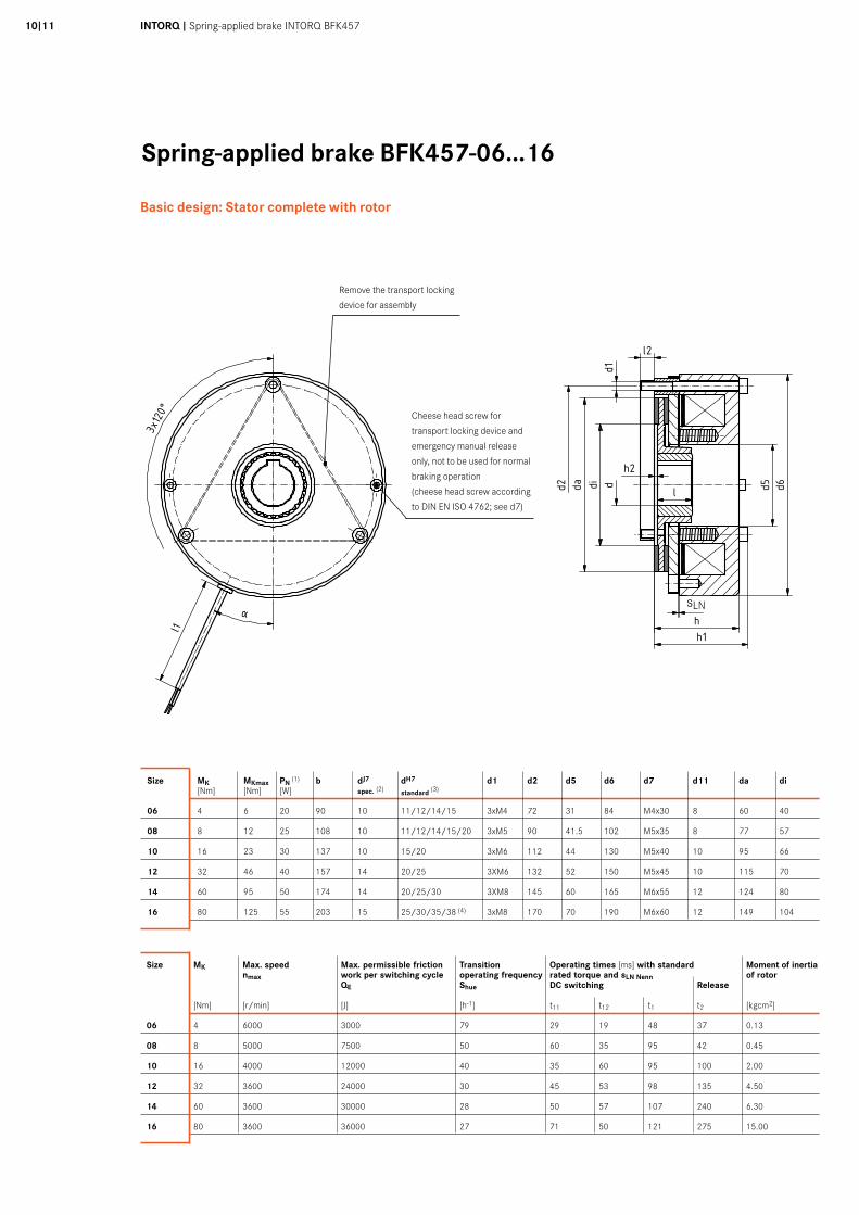
Size MK Max. speed Max. permissible friction Transition Operating times [ms] with standard Moment of inertia nmax work per switching cycle operating frequency rated torque and sLN Nenn of rotor QE Shue DC switching Release
[Nm] [r/min] [J] [h-1] t11 t12 t1 t2 [kgcm2]
06 4 6000 3000 79 29 19 48 37 0.13
08 8 5000 7500 50 60 35 95 42 0.45
10 16 4000 12000 40 35 60 95 100 2.00
12 32 3600 24000 30 45 53 98 135 4.50
14 60 3600 30000 28 50 57 107 240 6.30
16 80 3600 36000 27 71 50 121 275 15.00
Size MK MKmax PN (1) b dJ7 dH7 d1 d2 d3 d4 d5 d6 d7 d11 da di [Nm] [Nm] [W] spec. (2) standard (3)
06 4 6 20 90 10 11/12/14/15 3xM4 72 84 31 31 84 M4x30 8 60 40
08 8 12 25 108 10 11/12/14/15/20 3xM5 90 102 42 41.5 102 M5x35 8 77 57
10 16 23 30 137 10 15/20 3xM6 112 130 44 44 130 M5x40 10 95 66
12 32 46 40 157 14 20/25 3XM6 132 150 52 52 150 M5x45 10 115 70
14 60 95 50 174 14 20/25/30 3XM8 145 165 55 60 165 M6x55 12 124 80
16 80 125 55 203 15 25/30/35/38 (4) 3xM8 170 190 70 70 190 M6x60 12 149 104
sLN
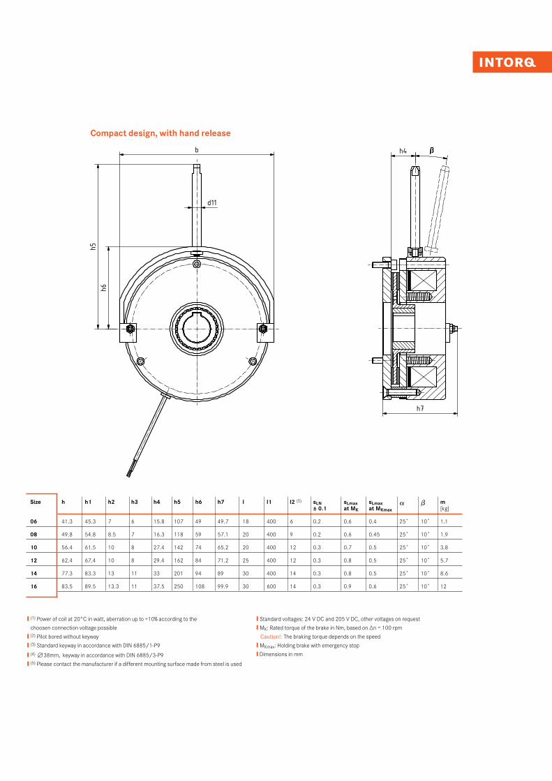
Compact design, with hand release
Größe MK MKmax P20° b d J7 vorg. 1) d H7 Standard 2) d1 d2 d3 d4 d5 d6 d7 d11 da di h h1 h2 h3 h4 h5 h6 h7 l l1 l2 3) SLN ±0,1 SLmax bei MK SLmax bei MKmax a a a a β β β β m
06 4 6 20 90 10 11 / 12 / 14 / 15 3xM4 72 84 31 31 84 M4x30 8 60 40 41,3 45,3 7 6 15,8 107 49 49,7 18 400 6 0,2 0,6 0,4 25° 10° 1,108 8 12 25 108 10 11 / 12 / 14 / 15 / 20 3xM5 90 102 42 41,5 102 M5x35 8 77 57 49,8 54,8 8,5 7 16,3 118 59 57,1 20 400 9 0,2 0,6 0,45 25° 10° 1,910 16 23 30 137 10 15 / 20 3xM6 112 130 44 44 130 M5x40 10 95 66 56,4 61,5 10 8 27,4 142 74 65,2 20 400 12 0,3 0,7 0,5 25° 10° 3,812 32 46 40 157 14 20 / 25 3xM6 132 150 52 52 150 M5x45 10 115 70 62,4 67,4 10 8 29,4 162 84 71,2 25 400 12 0,3 0,8 0,5 25° 10° 5,714 60 95 50 174 14 20 / 25 / 30 3xM8 145 165 55 60 165 M6x55 12 124 80 77,3 83,3 13 11 33 201 94 89 30 400 14 0,3 0,8 0,5 25° 10° 8,616 80 125 55 203 15 25 / 30 / 35 / 38 3xM8 170 190 70 70 190 M6x60 12 149 104 83,5 89,5 13,3 11 37,5 250 108 99,9 30 600 14 0,3 0,9 0,6 25° 10° 12
• 1) vorgebohrt ohne Nut• 2) Standardpassfedernut nach DIN 6885/1-P9• 3) Bei abweichender Anschraubfläche aus Stahl ist Rücksprache mit Hersteller erforderlich
• Standardspannungen bei : - Baugröße 06-12: 24 V , 205 V - Baugröße 14-16: 24 V , 42V , 205 V • MK: Kennmoment der Bremse in Nm , bezogen auf ∆n = 100 r/min Achtung: Bremsmoment ist drehzahlabhängig• P20°: Leistung der Spule bei 20°C in Watt, Abweichnung bis zu ±10% in Abhängigkeit der gewählten Anschlussspannung möglich• Alle Maße in mm
5020
1030
40m
m0
Schu
tzve
rmer
k IS
O 1
6016
bea
chte
n. C
opyr
ight
rese
rved
.
1 2 3 4 5 6 7 8 9 10 11 12
A
B
C
D
E
F
G
H
1 2 3 4 5 6 7 8 9 10 11 12
A
B
C
D
E
F
G
H
Ind./ Anz./ind. quan.
Änder-Nr./revision no.
Datum/date
Name/name
Datum/date Name/name
Bea/drn
Gepr/chkd
Norm/appr
Datei/file
Benennung/name of drawing
Zeichnungsnummer/drawing no.
Ersatz fuer/back-up for
Blatt/sheetCAD
M14.0282_BFK457-16_Compakt.iami
StrateLogermann
13.02.201313.02.2013 Maßblatt Federkraftbremse
BFK457-06 bis 16 - Compakt und Basic
M14.0282Zeichnung gleicher Nr. vom 16.02.2000
14
6 - xxxxxx 13.02.2013 STR
d1
l2
h2
h3SLN
h
d5 d6d4
α
ldida
h1
l1
d2d3
b
d11
h6h5
h4
h7
d
BFK457 - Compact BFK457 - Compact mit Handlüftung
120°
3x
ββββ
❙ (1) Power of coil at 20°C in watt, aberration up to +10% according to the
choosen connection voltage possible
❙ (2) Pilot bored without keyway
❙ (3) Standard keyway in accordance with DIN 6885/1-P9
❙ (4) n38mm, keyway in accordance with DIN 6885/3-P9
❙ (5) Please contact the manufacturer if a different mounting surface made from steel is used
❙ Standard voltages: 24 V DC and 205 V DC, other voltages on request
❙ MK: Rated torque of the brake in Nm, based on ∆n = 100 rpm
Caution!: The braking torque depends on the speed
❙ MKmax: Holding brake with emergency stop
❙ Dimensions in mm
Size h h1 h2 h3 h4 h5 h6 h7 l l1 l2 (5) sLN sLmax sLmax a b m ± 0.1 at MK at MKmax [kg]
06 41.3 45.3 7 6 15.8 107 49 49.7 18 400 6 0.2 0.6 0.4 25˚ 10˚ 1.1
08 49.8 54.8 8.5 7 16.3 118 59 57.1 20 400 9 0.2 0.6 0.45 25˚ 10˚ 1.9
10 56.4 61.5 10 8 27.4 142 74 65.2 20 400 12 0.3 0.7 0.5 25˚ 10˚ 3.8
12 62.4 67.4 10 8 29.4 162 84 71.2 25 400 12 0.3 0.8 0.5 25˚ 10˚ 5.7
14 77.3 83.3 13 11 33 201 94 89 30 400 14 0.3 0.8 0.5 25˚ 10˚ 8.6
16 83.5 89.5 13.3 11 37.5 250 108 99.9 30 600 14 0.3 0.9 0.6 25˚ 10˚ 12
10I11 INTORQ I Spring-applied brake INTORQ BFK457
Spring-applied brake BFK457-06...16
Größe MK MKmax P20° b d J7 vorg. 1) d H7 Standard 2) d1 d2 d5 d6 d7 d11 da di h h1 h2 h4 h5 h6 h7 l l1 l2 3) SLN ±0,1 SLmax bei MK SLmax bei MKmax a a a a β β β β m
06 4 6 20 90 10 11 / 12 / 14 / 15 3xM4 72 31 84 M4x30 8 60 40 35,3 39,3 1 15,8 107 49 43,7 18 400 9,7 0,2 0,6 0,4 25° 10° 0,908 8 12 25 108 10 11 / 12 / 14 / 15 / 20 3xM5 90 41,5 102 M5x35 8 77 57 42,8 47,8 1,5 16,3 118 59 50,1 20 400 12,2 0,2 0,6 0,45 25° 10° 1,510 16 23 30 137 10 15 / 20 3xM6 112 44 130 M5x40 10 95 66 48,4 54,5 2 27,4 142 74 57,2 20 400 11,5 0,3 0,7 0,5 25° 10° 312 32 46 40 157 14 20 / 25 3xM6 132 52 150 M5x45 10 115 70 54,4 60,4 2 29,4 162 84 63,2 25 400 11 0,3 0,8 0,5 25° 10° 4,714 60 95 50 174 14 20 / 25 / 30 3xM8 145 60 165 M6x55 12 124 80 66,3 74,3 2 33 201 94 78 30 400 14 0,3 0,8 0,5 25° 10° 7,116 80 125 55 203 15 25 / 30 / 35 / 38 3xM8 170 70 190 M6x60 12 149 104 72,5 80,5 2,25 37,5 250 108 88,9 30 600 12,5 0,3 0,9 0,6 25° 10° 10
• 1) vorgebohrt ohne Nut• 2) Standardpassfedernut nach DIN 6885/1-P9• 3) Bei abweichender Anschraubfläche aus Stahl ist Rücksprache mit Hersteller erforderlich
• Standardspannungen bei : - Baugröße 06-12: 24 V , 205 V - Baugröße 14-16: 24 V , 42V , 205 V • MK: Kennmoment der Bremse in Nm , bezogen auf ∆n = 100 r/min Achtung: Bremsmoment ist drehzahlabhängig• P20°: Leistung der Spule bei 20°C in Watt, Abweichnung bis zu ±10% in Abhängigkeit der gewählten Anschlussspannung möglich• Alle Maße in mm
5020
1030
40m
m0
Schu
tzve
rmer
k IS
O 1
6016
bea
chte
n. C
opyr
ight
rese
rved
.
1 2 3 4 5 6 7 8 9 10 11 12
A
B
C
D
E
F
G
H
1 2 3 4 5 6 7 8 9 10 11 12
A
B
C
D
E
F
G
H
Ind./ Anz./ind. quan.
Änder-Nr./revision no.
Datum/date
Name/name
Datum/date Name/name
Bea/drn
Gepr/chkd
Norm/appr
Datei/file
Benennung/name of drawing
Zeichnungsnummer/drawing no.
Ersatz fuer/back-up for
Blatt/sheetCAD
M14.0282_BFK457-16_Basic.iami
StrateLogermann
13.02.201313.02.2013 Maßblatt Federkraftbremse
BFK457-06 bis 16 - Compakt und Basic
M14.0282Zeichnung gleicher Nr. vom 16.02.2000
24
6 - xxxxxx 13.02.2013 STR
BFK457 - Basic BFK457 - Basic mit Handlüftung
Zylinderschraube nur für Transportsicherungund Nothandlüftung, nicht im Bremsbetrieb verwenden!(verwendete Zylinderschraube DIN 912 - siehe d7)
120°
3x
α
l1
l2
d1l
d
h2
Transportsicherungsgummivor Montage entfernen
SLN
h1h
d5 d6didad2
h6h5
d11
b h4
h7
ββββBasic design: Stator complete with rotor
Size MK Max. speed Max. permissible friction Transition Operating times [ms] with standard Moment of inertia nmax work per switching cycle operating frequency rated torque and sLN Nenn of rotor QE Shue DC switching Release
[Nm] [r/min] [J] [h-1] t11 t12 t1 t2 [kgcm2]
06 4 6000 3000 79 29 19 48 37 0.13
08 8 5000 7500 50 60 35 95 42 0.45
10 16 4000 12000 40 35 60 95 100 2.00
12 32 3600 24000 30 45 53 98 135 4.50
14 60 3600 30000 28 50 57 107 240 6.30
16 80 3600 36000 27 71 50 121 275 15.00
Größe MK MKmax P20° b d J7 vorg. 1) d H7 Standard 2) d1 d2 d5 d6 d7 d11 da di h h1 h2 h4 h5 h6 h7 l l1 l2 3) SLN ±0,1 SLmax bei MK SLmax bei MKmax a a a a β β β β m
06 4 6 20 90 10 11 / 12 / 14 / 15 3xM4 72 31 84 M4x30 8 60 40 35,3 39,3 1 15,8 107 49 43,7 18 400 9,7 0,2 0,6 0,4 25° 10° 0,908 8 12 25 108 10 11 / 12 / 14 / 15 / 20 3xM5 90 41,5 102 M5x35 8 77 57 42,8 47,8 1,5 16,3 118 59 50,1 20 400 12,2 0,2 0,6 0,45 25° 10° 1,510 16 23 30 137 10 15 / 20 3xM6 112 44 130 M5x40 10 95 66 48,4 54,5 2 27,4 142 74 57,2 20 400 11,5 0,3 0,7 0,5 25° 10° 312 32 46 40 157 14 20 / 25 3xM6 132 52 150 M5x45 10 115 70 54,4 60,4 2 29,4 162 84 63,2 25 400 11 0,3 0,8 0,5 25° 10° 4,714 60 95 50 174 14 20 / 25 / 30 3xM8 145 60 165 M6x55 12 124 80 66,3 74,3 2 33 201 94 78 30 400 14 0,3 0,8 0,5 25° 10° 7,116 80 125 55 203 15 25 / 30 / 35 / 38 3xM8 170 70 190 M6x60 12 149 104 72,5 80,5 2,25 37,5 250 108 88,9 30 600 12,5 0,3 0,9 0,6 25° 10° 10
• 1) vorgebohrt ohne Nut• 2) Standardpassfedernut nach DIN 6885/1-P9• 3) Bei abweichender Anschraubfläche aus Stahl ist Rücksprache mit Hersteller erforderlich
• Standardspannungen bei : - Baugröße 06-12: 24 V , 205 V - Baugröße 14-16: 24 V , 42V , 205 V • MK: Kennmoment der Bremse in Nm , bezogen auf ∆n = 100 r/min Achtung: Bremsmoment ist drehzahlabhängig• P20°: Leistung der Spule bei 20°C in Watt, Abweichnung bis zu ±10% in Abhängigkeit der gewählten Anschlussspannung möglich• Alle Maße in mm
5020
1030
40m
m0
Schu
tzve
rmer
k IS
O 1
6016
bea
chte
n. C
opyr
ight
rese
rved
.
1 2 3 4 5 6 7 8 9 10 11 12
A
B
C
D
E
F
G
H
1 2 3 4 5 6 7 8 9 10 11 12
A
B
C
D
E
F
G
H
Ind./ Anz./ind. quan.
Änder-Nr./revision no.
Datum/date
Name/name
Datum/date Name/name
Bea/drn
Gepr/chkd
Norm/appr
Datei/file
Benennung/name of drawing
Zeichnungsnummer/drawing no.
Ersatz fuer/back-up for
Blatt/sheetCAD
M14.0282_BFK457-16_Basic.iami
StrateLogermann
13.02.201313.02.2013 Maßblatt Federkraftbremse
BFK457-06 bis 16 - Compakt und Basic
M14.0282Zeichnung gleicher Nr. vom 16.02.2000
24
6 - xxxxxx 13.02.2013 STR
BFK457 - Basic BFK457 - Basic mit Handlüftung
Zylinderschraube nur für Transportsicherungund Nothandlüftung, nicht im Bremsbetrieb verwenden!(verwendete Zylinderschraube DIN 912 - siehe d7)
120°
3x
α
l1
l2
d1
l
d
h2
Transportsicherungsgummivor Montage entfernen
SLN
h1h
d5 d6didad2
h6h5
d11
b h4
h7
ββββ
Remove the transport locking
device for assembly
Cheese head screw for
transport locking device and
emergency manual release
only, not to be used for normal
braking operation
(cheese head screw according
to DIN EN ISO 4762; see d7)
Size MK MKmax PN (1) b dJ7 dH7 d1 d2 d5 d6 d7 d11 da di [Nm] [Nm] [W] spec. (2) standard (3)
06 4 6 20 90 10 11/12/14/15 3xM4 72 31 84 M4x30 8 60 40
08 8 12 25 108 10 11/12/14/15/20 3xM5 90 41.5 102 M5x35 8 77 57
10 16 23 30 137 10 15/20 3xM6 112 44 130 M5x40 10 95 66
12 32 46 40 157 14 20/25 3XM6 132 52 150 M5x45 10 115 70
14 60 95 50 174 14 20/25/30 3XM8 145 60 165 M6x55 12 124 80
16 80 125 55 203 15 25/30/35/38 (4) 3xM8 170 70 190 M6x60 12 149 104
sLN
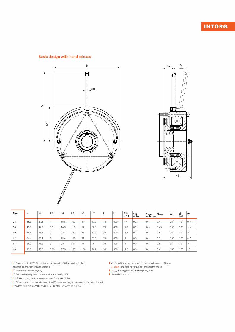
❙ (1) Power of coil at 20°C in watt, aberration up to +10% according to the
choosen connection voltage possible
❙ (2) Pilot bored without keyway
❙ (3) Standard keyway in accordance with DIN 6885/1-P9
❙ (4) n38mm, keyway in accordance with DIN 6885/3-P9
❙ (5) Please contact the manufacturer if a different mounting surface made from steel is used
❙ Standard voltages: 24 V DC and 205 V DC, other voltages on request
❙ MK: Rated torque of the brake in Nm, based on ∆n = 100 rpm
Caution!: The braking torque depends on the speed
❙ MKmax: Holding brake with emergency stop
❙ Dimensions in mm
Basic design with hand release
Größe MK MKmax P20° b d J7 vorg. 1) d H7 Standard 2) d1 d2 d5 d6 d7 d11 da di h h1 h2 h4 h5 h6 h7 l l1 l2 3) SLN ±0,1 SLmax bei MK SLmax bei MKmax a a a a β β β β m
06 4 6 20 90 10 11 / 12 / 14 / 15 3xM4 72 31 84 M4x30 8 60 40 35,3 39,3 1 15,8 107 49 43,7 18 400 9,7 0,2 0,6 0,4 25° 10° 0,908 8 12 25 108 10 11 / 12 / 14 / 15 / 20 3xM5 90 41,5 102 M5x35 8 77 57 42,8 47,8 1,5 16,3 118 59 50,1 20 400 12,2 0,2 0,6 0,45 25° 10° 1,510 16 23 30 137 10 15 / 20 3xM6 112 44 130 M5x40 10 95 66 48,4 54,5 2 27,4 142 74 57,2 20 400 11,5 0,3 0,7 0,5 25° 10° 312 32 46 40 157 14 20 / 25 3xM6 132 52 150 M5x45 10 115 70 54,4 60,4 2 29,4 162 84 63,2 25 400 11 0,3 0,8 0,5 25° 10° 4,714 60 95 50 174 14 20 / 25 / 30 3xM8 145 60 165 M6x55 12 124 80 66,3 74,3 2 33 201 94 78 30 400 14 0,3 0,8 0,5 25° 10° 7,116 80 125 55 203 15 25 / 30 / 35 / 38 3xM8 170 70 190 M6x60 12 149 104 72,5 80,5 2,25 37,5 250 108 88,9 30 600 12,5 0,3 0,9 0,6 25° 10° 10
• 1) vorgebohrt ohne Nut• 2) Standardpassfedernut nach DIN 6885/1-P9• 3) Bei abweichender Anschraubfläche aus Stahl ist Rücksprache mit Hersteller erforderlich
• Standardspannungen bei : - Baugröße 06-12: 24 V , 205 V - Baugröße 14-16: 24 V , 42V , 205 V • MK: Kennmoment der Bremse in Nm , bezogen auf ∆n = 100 r/min Achtung: Bremsmoment ist drehzahlabhängig• P20°: Leistung der Spule bei 20°C in Watt, Abweichnung bis zu ±10% in Abhängigkeit der gewählten Anschlussspannung möglich• Alle Maße in mm
5020
1030
40m
m0
Schu
tzve
rmer
k IS
O 1
6016
bea
chte
n. C
opyr
ight
rese
rved
.
1 2 3 4 5 6 7 8 9 10 11 12
A
B
C
D
E
F
G
H
1 2 3 4 5 6 7 8 9 10 11 12
A
B
C
D
E
F
G
H
Ind./ Anz./ind. quan.
Änder-Nr./revision no.
Datum/date
Name/name
Datum/date Name/name
Bea/drn
Gepr/chkd
Norm/appr
Datei/file
Benennung/name of drawing
Zeichnungsnummer/drawing no.
Ersatz fuer/back-up for
Blatt/sheetCAD
M14.0282_BFK457-16_Basic.iami
StrateLogermann
13.02.201313.02.2013 Maßblatt Federkraftbremse
BFK457-06 bis 16 - Compakt und Basic
M14.0282Zeichnung gleicher Nr. vom 16.02.2000
24
6 - xxxxxx 13.02.2013 STR
BFK457 - Basic BFK457 - Basic mit Handlüftung
Zylinderschraube nur für Transportsicherungund Nothandlüftung, nicht im Bremsbetrieb verwenden!(verwendete Zylinderschraube DIN 912 - siehe d7)
120°
3x
α
l1
l2
d1
l
d
h2
Transportsicherungsgummivor Montage entfernen
SLN
h1h
d5 d6didad2
h6h5
d11
b h4
h7
ββββ
Size h h1 h2 h4 h5 h6 h7 l l1 l2 (5) sLN sLmax sLmax a b m ± 0.1 at MK at MKmax [kg]
06 35.3 39.3 1 15.8 107 49 43.7 18 400 9.7 0.2 0.6 0.4 25˚ 10˚ 0.9
08 42.8 47.8 1.5 16.3 118 59 50.1 20 400 12.2 0.2 0.6 0.45 25˚ 10˚ 1.5
10 48.4 54.5 2 27.4 142 74 57.2 20 400 11.5 0.3 0.7 0.5 25˚ 10˚ 3
12 54.4 60.4 2 29.4 162 84 63.2 25 400 11 0.3 0.8 0.5 25˚ 10˚ 4.7
14 66.3 74.3 2 33 201 94 78 30 400 14 0.3 0.8 0.5 25˚ 10˚ 7.1
16 72.5 80.5 2.25 37.5 250 108 88.9 30 600 12.5 0.3 0.9 0.6 25˚ 10˚ 10
INTORQ I Spring-applied brake INTORQ BFK45712I13
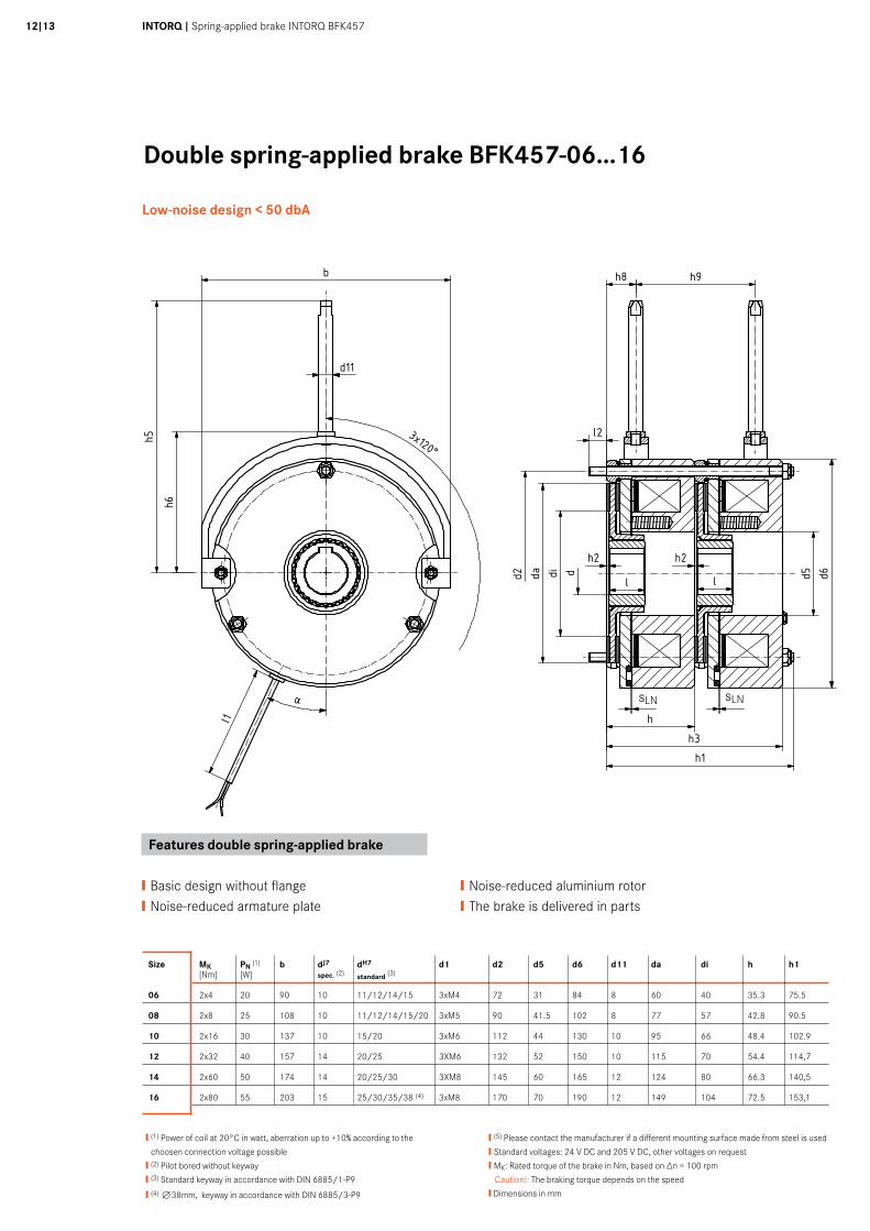
Double spring-applied brake BFK457-06...16
Low-noise design < 50 dbA
Größe MK P20° b d J7 vorg. 1) d H7 Standard 2) d1 d2 d5 d6 d11 da di h h1 h2 h5 h6 h8 h9 l l1 l2 3) SLN ±0,1 SLmax bei MK a a a a m
06 2x4 20 90 10 11 / 12 / 14 / 15 3xM4 72 31 84 8 60 40 35,3 75,5 1 109 54 13 44 18 400 6 0,2 0,5 25° 1,908 2x8 25 108 10 11 / 12 / 14 / 15 / 20 3xM5 90 41,5 102 8 77 57 42,8 90,5 1,5 121,7 62 12,7 63,3 20 400 9 0,2 0,5 25° 3,210 2x16 30 137 10 15 / 20 3xM6 112 44 130 10 95 66 48,4 102,9 2 147 84 16 70 20 400 11 0,3 0,5 25° 6,412 2x32 40 157 14 20 / 25 3xM6 132 52 150 10 115 70 54,4 60,4 2 166 93 18,3 78,4 25 400 11 0,3 0,75 25° 9,814 2x60 50 174 14 20 / 25 / 30 3xM8 145 60 165 12 124 80 66,3 74,3 2 186 106 22 91,5 30 400 14 0,3 0,75 25° 14,816 2x80 55 203 15 25 / 30 / 35 / 38 3xM8 170 70 190 12 149 104 72,5 80,5 2,25 230 120,5 24,5 100 30 600 14 0,3 0,75 25° 21
• 1) vorgebohrt ohne Nut• 2) Standardpassfedernut nach DIN 6885/1-P9• 3) Bei abweichender Anschraubfläche aus Stahl ist Rücksprache mit Hersteller erforderlich
• Standardspannungen bei : - Baugröße 06-12: 24 V , 205 V - Baugröße 14-16: 24 V , 42V , 205 V • MK: Kennmoment der Bremse in Nm , bezogen auf ∆n = 100 r/min Achtung: Bremsmoment ist drehzahlabhängig• P20°: Leistung der Spule bei 20°C in Watt, Abweichnung bis zu ±10% in Abhängigkeit der gewählten Anschlussspannung möglich• Alle Maße in mm
5020
1030
40m
m0
Schu
tzve
rmer
k IS
O 1
6016
bea
chte
n. C
opyr
ight
rese
rved
.
1 2 3 4 5 6 7 8 9 10 11 12
A
B
C
D
E
F
G
H
1 2 3 4 5 6 7 8 9 10 11 12
A
B
C
D
E
F
G
H
Ind./ Anz./ind. quan.
Änder-Nr./revision no.
Datum/date
Name/name
Datum/date Name/name
Bea/drn
Gepr/chkd
Norm/appr
Datei/file
Benennung/name of drawing
Zeichnungsnummer/drawing no.
Ersatz fuer/back-up for
Blatt/sheetCAD
i
StrateLogermann
22.02.201322.02.2013 Massblatt BFK457
Doppelbremse BG 06 - 16
M14.0299 22
h5
b
d11
α
h2 h2
l2
d5 d6dida dd2 l l
l1
SLN SLN
hh3h1
h8 h9
h6
120°3x
Size MK PN (1) b dJ7 dH7 d1 d2 d5 d6 d11 da di h h1 [Nm] [W] spec. (2) standard (3)
06 2x4 20 90 10 11/12/14/15 3xM4 72 31 84 8 60 40 35.3 75.5
08 2x8 25 108 10 11/12/14/15/20 3xM5 90 41.5 102 8 77 57 42.8 90.5
10 2x16 30 137 10 15/20 3xM6 112 44 130 10 95 66 48.4 102.9
12 2x32 40 157 14 20/25 3XM6 132 52 150 10 115 70 54.4 114,7
14 2x60 50 174 14 20/25/30 3XM8 145 60 165 12 124 80 66.3 140,5
16 2x80 55 203 15 25/30/35/38 (4) 3xM8 170 70 190 12 149 104 72.5 153,1
❙ (1) Power of coil at 20°C in watt, aberration up to +10% according to the
choosen connection voltage possible
❙ (2) Pilot bored without keyway
❙ (3) Standard keyway in accordance with DIN 6885/1-P9
❙ (4) n38mm, keyway in accordance with DIN 6885/3-P9
❙ (5) Please contact the manufacturer if a different mounting surface made from steel is used
❙ Standard voltages: 24 V DC and 205 V DC, other voltages on request
❙ MK: Rated torque of the brake in Nm, based on ∆n = 100 rpm
Caution!: The braking torque depends on the speed
❙ Dimensions in mm
Features double spring-applied brake
❙Basic design without flange❙Noise-reduced armature plate
❙Noise-reduced aluminium rotor❙The brake is delivered in parts
sLN sLN
Größe MK P20° b d J7 vorg. 1) d H7 Standard 2) d1 d2 d5 d6 d11 da di h h1 h2 h5 h6 h8 h9 l l1 l2 3) SLN ±0,1 SLmax bei MK a a a a m
06 2x4 20 90 10 11 / 12 / 14 / 15 3xM4 72 31 84 8 60 40 35,3 75,5 1 109 54 13 44 18 400 6 0,2 0,5 25° 1,908 2x8 25 108 10 11 / 12 / 14 / 15 / 20 3xM5 90 41,5 102 8 77 57 42,8 90,5 1,5 121,7 62 12,7 63,3 20 400 9 0,2 0,5 25° 3,210 2x16 30 137 10 15 / 20 3xM6 112 44 130 10 95 66 48,4 102,9 2 147 84 16 70 20 400 11 0,3 0,5 25° 6,412 2x32 40 157 14 20 / 25 3xM6 132 52 150 10 115 70 54,4 60,4 2 166 93 18,3 78,4 25 400 11 0,3 0,75 25° 9,814 2x60 50 174 14 20 / 25 / 30 3xM8 145 60 165 12 124 80 66,3 74,3 2 186 106 22 91,5 30 400 14 0,3 0,75 25° 14,816 2x80 55 203 15 25 / 30 / 35 / 38 3xM8 170 70 190 12 149 104 72,5 80,5 2,25 230 120,5 24,5 100 30 600 14 0,3 0,75 25° 21
• 1) vorgebohrt ohne Nut• 2) Standardpassfedernut nach DIN 6885/1-P9• 3) Bei abweichender Anschraubfläche aus Stahl ist Rücksprache mit Hersteller erforderlich
• Standardspannungen bei : - Baugröße 06-12: 24 V , 205 V - Baugröße 14-16: 24 V , 42V , 205 V • MK: Kennmoment der Bremse in Nm , bezogen auf ∆n = 100 r/min Achtung: Bremsmoment ist drehzahlabhängig• P20°: Leistung der Spule bei 20°C in Watt, Abweichnung bis zu ±10% in Abhängigkeit der gewählten Anschlussspannung möglich• Alle Maße in mm
5020
1030
40m
m0
Schu
tzve
rmer
k IS
O 1
6016
bea
chte
n. C
opyr
ight
rese
rved
.
1 2 3 4 5 6 7 8 9 10 11 12
A
B
C
D
E
F
G
H
1 2 3 4 5 6 7 8 9 10 11 12
A
B
C
D
E
F
G
H
Ind./ Anz./ind. quan.
Änder-Nr./revision no.
Datum/date
Name/name
Datum/date Name/name
Bea/drn
Gepr/chkd
Norm/appr
Datei/file
Benennung/name of drawing
Zeichnungsnummer/drawing no.
Ersatz fuer/back-up for
Blatt/sheetCAD
i
StrateLogermann
22.02.201322.02.2013 Massblatt BFK457
Doppelbremse BG 06 - 16
M14.0299 22
h5
b
d11
α
h2 h2
l2
d5 d6dida dd2 l l
l1
SLN SLN
hh3h1
h8 h9
h6
120°3x
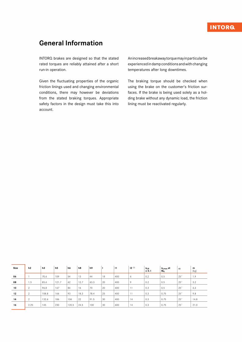
Size h2 h3 h5 h6 h8 h9 l l1 l2 (5) sLN sLmax at a m ± 0.1 MK [kg]
06 1 70.6 109 54 13 44 18 400 6 0.2 0.5 25˚ 1.9
08 1.5 85.6 121.7 62 12.7 63.3 20 400 9 0.2 0.5 25˚ 3.2
10 2 96.8 147 84 16 70 20 400 11 0.3 0.5 25˚ 6.4
12 2 108.8 166 93 18.3 78.4 25 400 11 0.3 0.75 25˚ 9.8
14 2 132.6 186 106 22 91.5 30 400 14 0.3 0.75 25˚ 14.8
16 2.25 145 230 120.5 24.5 100 30 600 14 0.3 0.75 25˚ 21.0
INTORQ brakes are designed so that the stated rated torques are reliably attained after a short run-in operation.
Given the fluctuating properties of the organic friction linings used and changing environmental conditions, there may however be deviations from the stated braking torques. Appropriate safety factors in the design must take this into account.
An increased breakaway torque may in particular be experienced in damp conditions and with changing temperatures after long downtimes.
The braking torque should be checked when using the brake on the customer's friction sur-faces. If the brake is being used solely as a hol-ding brake without any dynamic load, the friction lining must be reactivated regularly.
General Information
INTORQ I Spring-applied brake INTORQ BFK45714I15
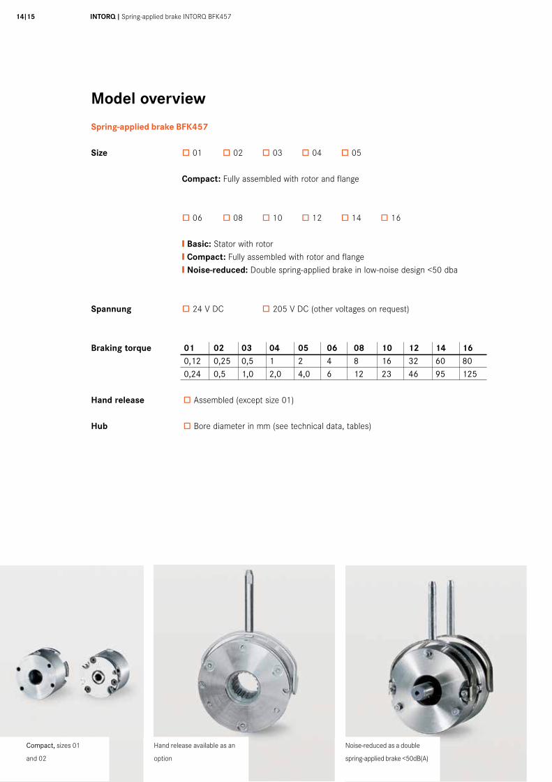
Model overview
Spring-applied brake BFK457
Size ò 01 ò 02 ò 03 ò 04 ò 05 Compact: Fully assembled with rotor and flange
ò 06 ò 08 ò 10 ò 12 ò 14 ò 16 ❙ Basic: Stator with rotor ❙ Compact: Fully assembled with rotor and flange ❙ Noise-reduced: Double spring-applied brake in low-noise design <50 dba
Spannung ò 24 V DC ò 205 V DC (other voltages on request)
Braking torque 01 02 03 04 05 06 08 10 12 14 16 0,12 0,25 0,5 1 2 4 8 16 32 60 80 0,24 0,5 1,0 2,0 4,0 6 12 23 46 95 125 Hand release ò Assembled (except size 01)
Hub ò Bore diameter in mm (see technical data, tables)
Hand release available as an
option
Noise-reduced as a double
spring-applied brake <50dB(A)
Compact, sizes 01
and 02

We are available to our customers at all times and in all locations. Major customers and projects are supported directly by our Key Account Sales Team at our HQ in Aerzen (Germany) or by our locations in Shanghai (China), Atlanta (USA) and Pune (India).
In addition to this, we work with a global network of local trading partners and cooperate with Lenze's global sales organisation.
Please send service requests directly to your local sales partner or to our HQ in Aerzen, Germany:E-mail [email protected]: +49 5154 70534-222Fax: +49 5154 70534-200
You can find more information on our products, as well as catalogues and operating instructions available for download, on our website at www.intorq.de
Setting standards in the market, worldwide
www.intorq.com1334
3758
Te
chni
cal a
ltera
tions
res
erve
d ❚ P
rinte
d in
Ger
man
y 04
.201
7 en
❚ 3.
0
INTORQ GmbH & Co. KG
Postfach 1103D-31849 Aerzen, Germany
Wülmser Weg 5D-31855 Aerzen, Germany
Tel: +49 5154 70534-0(Head office)Tel: +49 5154 70534-222(Sales department)Fax: +49 5154 70534-200E-mail [email protected]
INTORQ (Shanghai) CO., LTDChina
No. 600, Xin Yuan Nan Road,Building No. 6 / Zone BNicheng town, PudongShanghai, China 201306
Tel: +86 21 20363-810Fax: +86 21 20363-805E-mail [email protected]
INTORQ US INC.USA
300 Lake Ridge Drive SESmyrna, GA 30082, USA
Tel: +1 678 236-0555Fax: +1 678 309-1157E-mail [email protected]
INTORQ India Pvt. Ltd.India
Plot No. E-7/3, Chakan Industrial Area, Phase 3, Nighoje, Taluka-Khed, Pune, 410501 Maharashtra
Tel: +91 21 3562-5500E-mail [email protected]