spring check valve - worldbuild365 · testing: 100% testing in accordance with en 12266 ... flat...
TRANSCRIPT

112 www.brandoni.it
Serie 05
Che
ck v
alve
s
Spring check valve
FIRE FIGHTINGDRINKING WATER WATER CONDITIONING HEATINGINDUSTRY
Application fields

www.brandoni.it 113
1
2 3
5 4
Serie 05
Che
ck v
alve
s
Refer to specifications on page 120
In conformity with directive 97/23/CE PED Construction and testing norms (correspondences):
Flanges: EN 1092,Threading: ISO228-1 Design: EN13445, EN12334Marking: EN19Testing: 100% testing in accordance with EN 12266
Plugs for drain
Mini-valves for drain
Filter baskets (see Filtration section)
Double check group
1. Internal and external epoxy coatings, highly temperature resistant. Environmentally friendly water-based paint.
2. The stainless steel spring allows the valves to be assembled in any position.
3. Flat seal in NBR, FKM (Viton®) or silicon rubber
4. The shape of body and shutter minimizes turbulence and head loss.
5. On request: threaded holes for drain, by-pass.
The valves in Series 05 are check valves with cast iron bodies, that are manufactured in accordance with the most severe
product norms, and in conformity with the quality requirements of EN ISO 9001. They are available in flanged versions,
from DN 50 to DN 250, and in threaded versions, from DN 50 to DN 100.
The valves are suitable for installation in heating and conditioning plants (HVAC), for water treatment and distribution,
pump stations, agricultural applications, industrial applications, for compressed air, oils and hydrocarbons.
(Please ensure the choice of the corresponding item)
YES: for in-line installation (horizontal or vertical position) and as foot valves.
The shape of the body and shutter minimizes turbulence and head loss.
NO: for steam.
Accessories Special version

114 www.brandoni.it
C1
n° x D
CF
4
8
5 61 3.1 2
7
3
A
P
n° x D
C
F
351 24A1
T
P1
Serie
F5
DN
50-1
00Se
rie F
5 D
N12
5-25
0Se
rie T
5
1 234 5A
P
F5 D
N50
- 1
00F5
DN
125
- 25
0T
5
Che
ck v
alve
s
Spring check valve

www.brandoni.it 115
Cracking pressure (mmH2O)
Flow direction DN 40 50 65 80 100 125 150 200 250
639 639 647 592 624 570 526 639 690
382 382 316 280 318 180 165 221 204
510 510 480 436 470 375 345 429 448
withoutspring 125 125 165 155 152 203 185 208 244
Serie 05
Dimensions (mm)
Weight (kg)
DN 40 50 65 80 100 125 150 200 250P 50 50 65 80 100 125 145 194 242A Not standardized 100 100 120 140 170 200 230 300 370C 165 165 185 200 220 250 285 340 405F EN 1092 PN16 110 125 145 160 180 210 240 295 355n° x D 4 x M16 4 x 18 4 x 18 8 x 18 8 x 18 8 x 18 8 x 22 12 x 22 12 x 26T ISO 228-1 - 2" 2" -1/2 3" 4" - - - -P1 - 50 64 64 80 - - - -A1 Not standardized - 140 167 177 208 - - - -C1 - 96 125 125 148 - - - -
F5 5,6 5,6 7,6 9,8 13,8 20,6 28,6 48,6 81,4T5 - 2,2 3,2 4,2 7,4 - - - -
Che
ck v
alve
s
1
2
3
3.145678
Component
BodyStem guide DN50-100Stem guide DN125-250Stem guide DN200-250Shutter DN 50-100Shutter DN 125-250Shutter stemGasketSpringBushingAnti-blow out ringO-ring DN 200-250
Material
EN GJL 250CuZn40Pb2 / ASTM A351 gr. CF8MEN GJL 250 / ASTM A351 gr. CF8MASTM A216 gr. WCB / ASTM A351 gr. CF8MEN GJL 250 / ASTM A351 gr. CF8MEN GJL 250 / ASTM A351 gr. CF8MCuZn40Pb2 / ASTM A351 gr. CF8MNBR / FKM (Viton®)AISI 302BronzeAISI 302NBR / FKM (Viton®)
Materials

116 www.brandoni.it
NB: the maximum working pressure decreases while the temperature increases; please refer to “pressure/temperature” chartG1, L12, G2, L2: see chart to side
Temperature min ° C Max°C
continuous peak
L1 G2,L2 L1 G2,L2
NBR -10 100 100 - 110
FKM (Viton®) -10 100 150 - 170
Rubber for drinking water -10 - 70 - -
Che
ck v
alve
s
Spring check valve
500020001000300 50020010050302010
0,6
0,8
0,5
1
108
65
3
2
m H2O
mc/h
50
" 2-
"
"
4
DN
DN
65
DN
80
DN
150
DN
125
DN
100
DN
200
DN
250
2
2" 1
/
3
4
DN
40
Head loss Fluid: water (1m H2O = 0,098bar)
Pressure/temperature chart
Maximum pressure Temperature
*: Hazardous gas, liquids (explosive, inflammable, toxic) in accordance with 97/23/CE PED and 67/548/EEC
Fluids *
Hazardous gases G1
Hazardous liquids L1
All remaining fluids G2, L2
NO
16 bar DN50-20010 bar DN250
16 bar DN50-20010 bar DN250
RANGE NOT SUITABLE FOR STEAM. DO NOT use in case temperature and pressure are below the saturation line liquid-steam ( hatched area )
176140104 °F
1
bar
°C
20
10
20 40 60 80 100 160140120
psi
145
290
68 248 284212 320
Liquid - steam saturation line (fluid: water)
Minimum pressure refer to chart
Minimum Counterpressure 0,1 bar
Kv-DN chartDN 40 50 65 80 100 125 150 200 250Kv mc/h 99 99 145 258 360 516 620 985 1620
www.brandoni.it 117
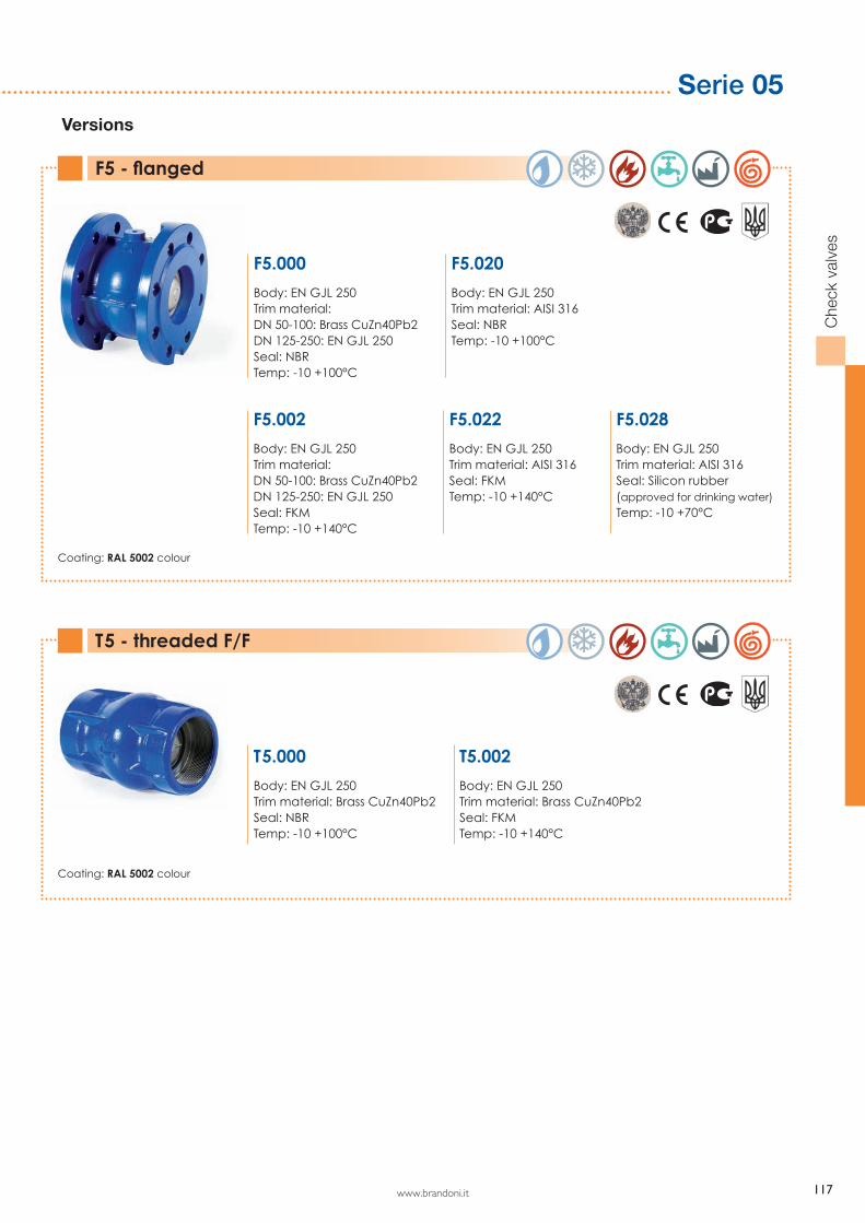
Coating: RAL 5002 colour
Coating: RAL 5002 colour
Serie 05
Che
ck v
alve
s
F5 - flanged
T5 - threaded F/F
F5.000
Body: EN GJL 250Trim material: DN 50-100: Brass CuZn40Pb2DN 125-250: EN GJL 250Seal: NBRTemp: -10 +100°C
T5.000
Body: EN GJL 250Trim material: Brass CuZn40Pb2Seal: NBRTemp: -10 +100°C
F5.020
Body: EN GJL 250Trim material: AISI 316Seal: NBRTemp: -10 +100°C
T5.002
Body: EN GJL 250Trim material: Brass CuZn40Pb2Seal: FKMTemp: -10 +140°C
F5.002
Body: EN GJL 250Trim material: DN 50-100: Brass CuZn40Pb2DN 125-250: EN GJL 250Seal: FKMTemp: -10 +140°C
F5.022
Body: EN GJL 250Trim material: AISI 316Seal: FKMTemp: -10 +140°C
F5.028
Body: EN GJL 250Trim material: AISI 316Seal: Silicon rubber(approved for drinking water)Temp: -10 +70°C
Versions

118 www.brandoni.it
Che
ck v
alve
s
Foot valve
C1T
F
C
n° x Df
A
B
L
f
A1
B1
L1
F5 +
50
T5
+ 5
1
Dimensions (mm)
Weight (kg)
DN 40 50 65 80 100 125 150 200 250A Not standardized 180 180 220 260 320 375 430 550 670L 80 80 100 120 150 175 200 250 300B 111 111 131 148 168 198 222 278 329C 165 165 185 200 220 250 285 340 405F EN 1092 PN16 110 125 145 160 180 210 240 295 355n° x D 4 x M16 4 x 18 4 x 18 8 x 18 8 x 18 8 x 18 8 x 22 12 x 22 12 x 26T ISO 228-1 - 2" 2" -1/2 3" 4" - - - -A1 Not standardized - 225 252 282 326 - - - -L1 85 85 105 118 - - - -C1 - 96 125 125 148 - - - -f 5 5 5 5 5 5 5 5 5
kg F5+50/52/53 6,15 6,15 8,34 10,73 15 22,2 30,8 51,8 85,8kg T5+51 - 2,27 3,29 4,31 7,55 - - - -

www.brandoni.it 119
Serie 05
Che
ck v
alve
s
Flanged foot valve
Threaded foot valve F/F
Versions
F5.000+50
Body: EN GJL 250Trim material: DN 50-100: Brass CuZn40Pb2DN 125-250: EN GJL 250Seal: NBRTemp: -10 +100°CStrainer: galvanized steel
T5.000+51
Body: EN GJL 250Trim material: Brass CuZn40Pb2Seal: NBRTemp: -10 +100°CStrainer: AISI 304
F5.020+52
Body: EN GJL 250Trim material: AISI 316 Seal: NBRTemp: -10 +100°CStrainer: AISI 304
F5.020+53
Body: EN GJL 250Trim material: AISI 316 Seal: NBRTemp: -10 +100°CStrainer: AISI 316
Coating: RAL 5002 colour
Coating: RAL 5002 colour
120 www.brandoni.it
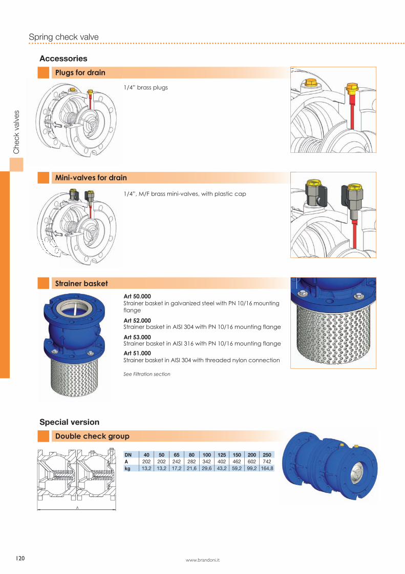
Accessories
Special version
Plugs for drain
Double check group
Mini-valves for drain
Strainer basket
1/4” brass plugs
1/4”, M/F brass mini-valves, with plastic cap
Art 50.000 Strainer basket in galvanized steel with PN 10/16 mounting flange
Art 52.000Strainer basket in AISI 304 with PN 10/16 mounting flange
Art 53.000Strainer basket in AISI 316 with PN 10/16 mounting flange
Art 51.000Strainer basket in AISI 304 with threaded nylon connection
See Filtration section
Che
ck v
alve
s
Spring check valve
DN 40 50 65 80 100 125 150 200 250A 202 202 242 282 342 402 462 602 742kg 13,2 13,2 17,2 21,6 29,6 43,2 59,2 99,2 164,8

www.brandoni.it 121
Serie 05
Che
ck v
alve
s
DN 40 50 65 80 100 125 150 200 250A 202 202 242 282 342 402 462 602 742kg 13,2 13,2 17,2 21,6 29,6 43,2 59,2 99,2 164,8
The information provided here is delivered with each product, and contains “Instructions for use and maintenance”; it is also available on our website: www.brandoni.it (download section)
STORINGKeep in a closed and dry place.
MAINTENANCEThe valve does not require maintenance.
RECOMMENDATIONSBefore carrying out maintenance or dismantling the valve:- be sure that the pipes, valves and fluids have cooled down, - that the pressure has decreased and that the lines and pipes have been drained in case of toxic, corrosive, inflammable and caustic liquids.Temperatures above 50°C and below 0°C might cause damage to people.
INSTALLATION- Handle with care. - Place the valve between the flanges of the pipe and install the seal between the pipe and valve flanges. Check that the seals have been positioned correctly.The distance between the counter flanges must be equal to the valve’s face to face distance. Do not use bolts of the counter flanges to bring the piping close to the valve. The bolts should be cross tightened.- Do not weld the flanges to the piping after installing the valve.- Water hammers might cause damage and ruptures. Inclination, twisting and misalignments of the piping may subject the installed valve to excessive stresses. It is recommended that elastic joints be used in order to reduce such effects as much as possible.- When in the open position, some valves have a larger dimension than the nominal face to face value. A suitable distance should be allowed for when assembling, in order to prevent damage or malfunctioning (see fig. 1 for example).
NOTE. This valve is unidirectional: install in accordance with the flow direction arrow indicated on the body.
Instruction and Recommendations
NON OK OK FIG. 1