springs. - defense technical information center · springs which predict dynamic value~s such as...
TRANSCRIPT

- Z -111 1
ru i - -ro--
~ ~ ~.Studl oi Stranded Mire Springs.
Reprouced rCA,
............ iec MM
mI M. . . .. . . . . . . .. .
F1 NU 1,
1 J i., -ý
1 "ivy I "I, -*
/ ~ ' R~ is~~ud ly7'20
Headq Aer J, ~
7.S py Wepn C~al
/ ~~/ / -~ii~iPON
i A I ItPo

MATH+METRIKI N C OR P 0 P A T E D
294 SANDBANY ROAD
I P. O. BOX 220 CHESHIRE
* CONNECTICUI 064 10
PI 'R 'XAL N MA,,.R PRES. TEL. 272.3650, 272.704A
MM - TR - 7008-F Cheshire ,Deceiner 197M.
Study of Dynamic Response in Stranded Wire Springs.
Final Technical Report
on[ Contract DAAF03-70-C-O078
r .to
Headquarters
U.S.Army Weapons Command
Rock IslandIL 61201
ATTN : AMSWE-RET
Distribution :
U.S.Army Weapons CommandRock lslandgIL 61201,ATTN : AMSWE-RET 3x
Copy No.
•f

-ii.'- -MM TR -7008-F
e Study of Rynamic Response of Stranded Wire Sbrih~s.
A,-BST R ACT
'. A total of 60 TD-recordings were made of 5' d-ifferent test springs,
42 records in, impact loading at velociie s up -to 560. inch/sect. ."and 18 records on the sudden release of springait extension velocities
up 146 830 inch/sec.,.Each record ras `u i h respoct to surge time (both wave
S-heo-d and wavve peak),,Iveioci-tie s , r-ininuum he-ight. reached, etCi-o
For single wire springs,the formul•,s of tile Surge Wave Theory
were recapi'tilated and suramar zed4.in eo-i- �n-.--l co'rme-
pending forijults were derived for stranded wire springs'Tkuse formu-
l s i use lumped values at par:-metersosuch &s the ,.ctive weight of
spring (or per coil) Und the measured rate of the spring (.or coil)9
intoacd of wiro diumeter d and mean coil diameter D).Whe 'using 'the icosured' ini~iql ,a-tc of spring in these formulis,
0good agrooment was reac'hed bet-%uen the calculated and the measured
f valacs.Thereforo-,a set of formulas is available now for sliunded wire
springs which predict dynamic value~s such as surge t,",inosurge velocity,
extensaion velocity in sudden release and induced load' and stress
within a few percent of, the measured values.,
S tranded wire springs were found to show a few phenomena over'
"ho'se observed on single wire" spfitugs:The surge velocity is not a
coistvant for all compression levels of springpbut increases, slightly
"•ith increasing compression.Thh slope of the wave head has a pronounced
ter,4ency to .bruoden during propagationzso that head and- peak ýf wave
-hav;e somewhot dilferent ,ýUrgi" velocities (about 10% difference)..
3 The wave head di'suppeors in the records after from 2 to 3,5 surge
times Ttas compared to 6T or 8T in single wire springs.
r -
i :L i- - .--- -------

-ii-.MMm.Tam7*L,ý.kFinal Report
std iofDyai -Stranded Wire Svr-ing-st.
Table 6if I'I'6itts No.of Pages
ill Section
Ai, Scope of Woik 2
B. Compiling basic sprii: , iaa2
C. Sanuary of surge wa.yi1 V*ormulaz on single wvire springs, 6
D. ~~ abishi e~t of stg~ wave- foruiulai on. stranded vire, springs 6
S.,L Pr e p rt on f test f£ix,,tures, Tor ýrocorffifig -spring responseY. 3-ýstrand SPIV spri-g' t~
Dis~cussiop-of TD-r cords on im.pa~ct loading 4-
'G. 3-strand SPIV 'IriVi- s;pring:-Di.scus;4on of TD)-reco-rdg obn- suddfen- release- 'of i§pring 2
H. 7.strahd SPIW drive' spring;-'Discussion of *TJI-rA'coi's on impacet load~ing--
. 7ý-str!Ind.SPIW Aiv spring:IDi'30tssion o'.C !h)..recolrrds on s uddtena re 1e e (,-f'pig
AJ. J-s.*1irand ',18 di,4V~e spring,:21)i~cus"'ion of TD".recoros -on impact I oddIn8
K. 71-str~.rd M85 dr~iv e spriig,:])iu~ssioxn of TiD-iecords onl -im&c~t l q3
1L. 7-strand M85 drive spring:-Di~i~cussion of T1Dn-records on sud'dex r 'ea oTfpýs. s'Dring
M, 7-.-:tihnd 20- mm gun drivespig.Di-scubsion of TJ)-records 6nira odng2
N. Atzor~uatiouL of sini~lo, -.urgq, z n .5,tad~ k air dn
[0. ~Comnpariaoii of meausuic't d4-cale I:Vd surge tiiweos T'. 2P,. Comipnrison of ineusu~rbd t tz~t ~s'o ulcidc
g. Summary of.mtjor co~Pxi~
RII Roecommunda-tions
Appendix A 2Basic ajL~' daii45 dat hta, I.gas 9
Appendix B z Addj-it~ublS Q' ~i ilg 4wt: "ti~~~o~~t~~~t.- &la. rn Drzcd *ccl.ted from, Theory
K:5Tablc- ,2 -chorts ,1 d1agrtmri9j- Appendix Z O : 0 awy~1ea of WtDwreciolra~a --dndder s cp 4r i.,t 6 cover .32

- A• - M- TR - 7008-1
§Studv o, D•namic RegDonse7of Strandd Vire- SprinUs.
A.tie ~of'Vgrk.
A. Scope of work in general.
Photograph the transient wave propagation in stranded wire springs
with a time-displacement camera under presckibed c6nditions of impact
velocitypmass weight and spring preloads.
Evaluate time-displacement, records azid obtain measured values
for timelcoil displacementvolocitypacceleration and spring force.V~" Determine the transient wave volocitypthe dynamic spring force and-°stress from the TD-ricords.Sovme tests will also be performed on pre-
compressed 'stranded wire. springs released suddenly to determine
expansion velocity -and characteristics.
Conduct a theoretical analysis and establish formulae for the
calculation of the dynamic load and' stress and the transient wavevelocity in stranded wire springs.
Correlwde theoretical resulis with experiment"l data and prepare
report on rindings.
2. Number of test apringds.Five stranded wire test springs~two of the 3-strand type and
three of the 7-strand type are to,-be investigated:
3-stwand drive spring -for SPIW Rifle;
ý*A 7-stranrd 'drive spring -for SPIW Rifle;ý
3-strand drive spring for Cal..SD M85-Machine Gun;
% 7-strand drive spring for Cal..50 M85 Machine Gun47-strand drive spring for 20 mm Machine Gun.
fr 3. Number of TD-records\ to be taken.
The Contractot shall record a total of 50 time-dispJacement records,
with usually 2 records each for a given condition of spring, loading.These 24 pairs of records may be composed as follows:
5 types of stranded wire, springs under impact,
"with two levels of preload each : 10 conditions
2 -types of stranded wire .springs under sudden
retLeaselwith 2 levels of preload each : 4 conditions.

A-A2 .KHE Tit e-
This makes for 14*-diffe~rent conditions or.28 record's totali
Another 22 records are extras 9tq be taken at different film speeds
and magnificationspai the need arises during thr, program.
4. Ivalua~tion of The-records. _____
All the records will be evaluated regardi~ng -measured values of
time ,coi-l displacementtrelocity, acceleration, surge velocity, spring
forceý -and stress.In additiont the -damping, of the. surgew waves over timie,and displacement will be evaluated.Aisopit wkill be-endeavored to
measure the degrege of damping of a .particular spring ~by a numerical:-at.
vale~sy b ~ ponent a in the energy tm -supposed the"'energy decay follows.4 such an exponential law.
5. TheoreticAl analysie -of..wave gropamation in stranded wire sgrinagThe transient wave velocity will be derived from the -General,
Wave Equation;
* d2y/dt2 = c2 . d2y/dX2 .
Thi geerl euatonmus ~e modified to account for' the energy deca
due to damping as inherent in stranded wire springs.At least an a~pproxi-mate solution will be sought fo,o determining the influence of dampin
r -on~the. wave velocity.
6. Technical Reports.The resýults of the, recordings-and -the analysis will- be adaqoately
covered in the form of Technical Report'g3 Quarterly Reports anid one'Final Report.The Third Quarterly, 'Report may, be inciluded FIn' the Final-Reportlif the Scope of Work ha.s been completed: by that time.Thesereports will contain some of the TDý-rdcords taken-as examples~which12 ~ are discussed in detail.Of the prints not coit,:ined in these reportsan extra set of ptnts will Lse~ forwarded separate*y.,

-B1 -M)M TA T- T008-4
" B, COXUvilinh bavic.-s~ring dala. -Tt-.78-
B. General.
On each of the 5 test- springs,'he basic dimensions Vere mresmzed; -
before as well as after the testing.Some of the springs (SPIW-7 andM85-7) took a definite set during the testing,while the other 3iprings maintained their free height.
The average pitch of thb midale coils of the springs,hf,at freeh-ight was. also measuredoter a length comprising from 30 to 60 coils-.With hf known,the displacement magnification q of a TD-record can bedetermine• iore accurately than from the free height hf of spring,*here the actual ends of the spring cannot be mark6d by special traces.
The force-deflection rate P/F of the springs was also calculat4ed-by means of' the conventional formkla for sin#ls wire springs ýand simplyadding the rates of the 3 or 7 single wire springs.Alsu*measiuredforce-ýrIdeflection diagrams. P(F) were mad~e available for each of the
5 ;test, prings •by AMSWE-RZT .t, was felt that a comparison between thecalculated and measured spring rates (static riates) is a necessary part
of this study.
SI"¢,:++.+ The basic, data are compiled in+ data sheet Xl,in Appendix X+ItS measured forcei •-f-lection& diagram P(F) is -plotted in Diagram 1,Appendix X.ThiS spring• mintained its free height during the testing.'The calculated -rate P/P * 1.38 lbs/inch and the measured-rate overth ki 1" o stro•ke (.,,. .40', lbs inchi) are. in cloea agreement.
Sthe are"in f
3. _A1V drive springM. strand.
Here, an inner guide rod of ,266" was selected.The spring endswere. -found to have a .somewý2t lesser diameter than the middle coils,ýblnding on, a somewhat larger rod- of .272" diameter.
+at eý in Appencix X gives the basic data and Diagram .page X3,illustrdtes the measured P/F-diagram.Here the rate, P/F mi1.85' lbs/inch 'calculated under simplifying asswnptions is substantiallyless than the rate- P/F = 2.10 lbs/inch measured over the first 5"'
~ •- "of stroke.,Thijs spring set from H. = 14o26" to 13,80" during testing.
+- (
S-3

-B2- - TR-7008-2
4. 3-itrand P185' drive spring.
The basid dh-ta are compiled in page X4 of Appendix X.
This spring is rather husky~wi-th an index D/d of only 8.62.
Furthermoreit is coiled extromely stepp,with an uncorrected solid
stress Ss approuching' 190;000 -psi.
4airam2 on page X6 of Appendix X ilJ.u,utrates the measured
force-deflection diagrm3,P(P)-,,according to the data furnished by
AMSWE-RET.Over the first 5 inches of strokewhere the characteristics
is rather linearp-a spring rate H ý- 11 .20 .!-s/incn
was measured.The spring rate calculated from the spring data
[assuming 3 wires in parallel] is R - 10.45 lbs/inch,
-ie.,about "7 % less.
The spring experienced only a minor set during testingfromH f = 18.30" to 11f - 18.20" o
5. 7-strand M85d-rive spring.
. The basic Lata are compiled on page X.5 of Appendix X and themeasured force-deflection diagram P(P)- is il.ustrated in Dia ram 2,-page X6,of the Appendix X.The calculated rate Lparallel single wirespriJhg4 assumed] of It 3.29 lbs/inch was found to be sub-stantial-ly less than R 4.0 lbs/inch as measured over thefirst 3 inches of stroke.Notice the great diflerence in rate and
characteristics with respect to the 3-wire strand spring for thesame gun,
This spring was found to take a substantial set during the testing,from 11f n 18.26" to H f 16.90" .This largo set is mostly dueto thV omission of the buffer in a few testspwhere the spring wasthen crushed solid by excessive kinetic energy -of the impact mass.
6. 7-strand 20 mm igun drive spring.
The basic cdata are compiled on page X7 of the Appendix X and thek •measured force-deflection characteristics P(F) is iliustrated in
Diagram 3,page X8pof Appendix XoThe calculated rate (parallel wiros]of R - 6.25 lbs/inch is well below the measured raie of
R - 1.50 lbs/inch 9over the first 10 inches of strolte)o
This ipring took only a very minor set during the testing,from 11f = 24.65" to iff = 24.5" and was found to have recoveredto the initial froe height after weeks.

-Cl- MM -T- 7008-2
C, Summary of surge wave formulas on single wire springao
T, Tgrminolotv.-
•a. jDiniosin [inch].
Sd Wire diameter
d*. Diam6ter of wire strand
D Outer diameter of coils
D i Inner di'ameter of coilsD Mean-coil diameterSH Height or length of spring
Hf Free height
H Solid height
H Initial height (preloaded) in impact. loading
H2 Initial height in sudden release recordings
-h Pitch of'coil
FP Deflection of spring-f Deflection per c6i.l
X Wire coordinate,measured along the wire'
LI Length of wire of one coil
L L, Length of wire of entire *",pring (active coils)
y Deflection of a point of wire of coordinate x
7 b. Times9 in~secJ or [ms].
t Time in general (variable)
t 0 Instant of impact or sudden release
TI Wave propagation time or "surge time",per coil
Wave propagation time or "surge time" through spring
(single length)
Th Surge time of the wavehead in first transition
Ts X Separation time of rear spring end in sudden release
4T Period of free vibration of spring in sudden release,K •when rear spring end is fixed.

-0C2- MM -TR -7008-2
C1•, TerminologvCuntinued.
C. yol'cities, [inch/secj.
c Velocity of .propaga;t#On" of wave along the wiro,
also called '"surge velocity",
v Impact velocity of impact mass on spring,
also extension velocity of spring bD' iin sudaen release
"Yv(xt) Velocity of any point on wire axisgof .mire abscissa x,
,at the instant of time t.
Av Kinetic amplitude of surge, wave
d, Weigdhts and forces~in [lbs].
w = mg Weight of spring (active coils onirv)
W = N.g Weight of impact mass
P Load at any spring pointsalso force at spring End.
P1 Preload of spring in impact loading
Preload of spring in sudden release recording
Ps Spring force at solid height
P(F) StLtiv forc,,-defleceLion diagram
AP Chanve of force induced by an impact of velocity v
S•-(Force omplitude of surge wave)
,[ ~~ea Stresseslin [p~i
G Modulus of alastJicity in tors-X.
S Stress at arly point of epi±ng (iat wire surfacc),(shear).
S1 Inititl static) stress of prelooaded spring (impt. t loading)
S5 Static stress at solid hei.ght of spring
AS Change of stres. induced by impact of velocity v
(stresse amplitude of surge wave)
.4.

jC -03- I1-TA - 7008-2
C1. Termineloey.iontinued.
f. Other values DimensionA
., Acceleration due t0 gravity,386.4 Linch/sec 2 ]r ,=Weight of spring material per inch3 [lbs/in.]S0 .283 lbs/inh'; for spring steel
" P/F Force-deflec:ion rate of spring [lbs/inch]
Rj= P/f Force-deflection rate per coil [lbs/in../coill_C = D/d Spring index [--Nt Number of total coils in spring [---1N Number of active coils only [___]u Potential at a point of spring,by definition [inch/sec]
au Change of potential induced by impact velocity v,(potential amplitude of surge wave as opposed to
kinetic amplitude v)
91a Radius of spiral of single wire around strand centerlineb Len-th of Iny of s.n--le wire~ulong str.nd cen~trlineb* Length of lay oif single wireabsolute - 2
t i M

-C4 - H! TR -- 7008-2
2, Basic wave equation and surge velocity.In the basic wave equation
dy/d2 c2 d2 y/dx2
the constant c denotes the velocity of propagation or"surge velocity"
in the linear medi-ou.For a helical compression s6ringthis surge
yelocity c is given by the formulaRpFf L1
2 [inch/sec] (2)o -----/g (A +*IP/DA
where
%Pf = : •,orce-deflection rate of one coil , [lbs/inch/coij
A : Cross-sectional area of wire ossinc! : Polar moment of inertia of wire e ross-section, [inch J.P
For a round wire sp these values dre:G d4
RPf = 1 -.... 3- , (3)
-.= (/4) . d2 (4)
I (t132) . d 0 (5)
The length of one coilystrictly speakingis slightly longer than
77-. ,by a factor k alightly above 1:
L1 k. ,D (6)
For a. roundwire springythe formula (2) for c then becomes;
Sd 2 G.g k
D 2 1 + d/2D
With k a 1.01 (conventional choice) and spring index D/1 = 7 (mean
value),the third factor in equation (7) becomes 1 ant, ve have the
simplified formula: d G . gc - D . (8)
For a spr.ýng from stee wire)this formula further simplifies bo: ]O=88p560, (did) [Inch/sac) (9)

C5 MM-•TR 7008-F
3. Surge time and natural frequency.
We disti-nguish between ýthe, surge time T' through the entire spring
and the surge t i'ne 'Di, per coil.In 4vd.luation of TD-recordsthe latter
should be giv, priority,due to thet slight uncertainty regarding the
accurate numbei of:active €oil's in a 4srings.1
/c=T/N kL/C' - K 7/bo D/c [sec/il]0 (10)
-Assuming k 1.01 LO, isoconventional,it follows from (8) and (%o)a
T . .N. . . .. ( 1 1 ) ,
dgG
•ithh:mean values of spring ,steol:
= TIN = 35., 0-6 Da/d o (12)
When defining the active solid height
14s = N . d (13),
an alternate formula for the surge time is obtained:
T 35.8 . I0-6 (D/d) 2 (14)
The latter form shows clearlythat the surge time T increases withthe square of the spring index DA/.
Natural frequency:
If it spring is fastened with one end,the spring will, oscillateat e. fundamental, natural frequencyywhere the period Of vibration
comprises 4 surge times T:
H, 1 A 1/4T [sec-] • (15)
With moan vaoues of spring steel:
700 d/ 2 N) (16)
With both spring ends fastened~the period of the fundamentalnaua rqec , bcmstwc h bvevleo quto 1)free vibration comprises only ? surge times T and the fundamental
natural frequency nI becomes twice the above value of equation (16).

-C6 - * - TR -7008-F
4. Sizle surv o W wvQ i•d amplitudes.
Tkie forcedmotioi, v(t) or a spring rrnd or of an intermediate point
x of springf generates a "single surgo wave",which hits a kinetig
Urjimlittfde of sqc velocity v. and u potent!,ql arnplitudelwhich can
bo expirossec in .. different ways:
Az , c h-.;rige of loaLd or force, AP , in [lbs]
a.3 i clinngu of stress (uncorrectedI), AS , in [psijits ich-inge of dcfltý.ction per coil, Af P in Lilich/coilj;
is ai chunge of potential, Adu , in [inch/secj.£9v del'izijtitto, u u v.
The, following formulas have beeb derived:
. 1 . .. I (17)
I, - (All/v) .(& s/Al') - .-,G"- (18)
1/V - 'r 3.17 .(O/). 1d) (19)
6lva 1 (by definition) (20)
With mean vailues for ,spring 3teelthese formulas specialize to:
ZW/v - 51.5. d3/) ALlbs/inch/soiJ (21)
,/v -I 131 [Psi/inch/secJ (22)
Af/v = 35.8 . 10- 6 . D2/1i (inch/coil per inch/socj.(23)
Hore the surprising result is:The stress change induced in thu spring
by a forced velocity v (such ais impact) is proportional to the velocity
v,but independent from the spring dimensions d and l).kEch inch/sec
of forced velocity changes the stress of the spring point .il question
by 131 psi.
1 t4

-D1 MM'- T .-'1008-F
D. Modification of formulas for stranded wire syrings.
1. Derivatioiitof general formul. for Surge velocity.
We return to the basic wave equation (1) and to the -general
formula, for the surge velocitywhich is also v-aiý for stranaed
wire springs:
(Q'g) (A + 4.1 /1)
where " R73.0 : force-deflection ra-te of one coilin [lLs/inchj,
and L : length of wire. in one coil, in {inch]oWith the exception of. the unusually husky 3-strand M85 drive
spring (Did = 8.62),the spring index D/d of ,the other 4 test springs
ranges from 11.3 to 15.With an index of 14,the term 4.1 p/D 2 drops toonIly 0,25% of the term A ahd therefore can be rightful'ly neglected.
When further introducing. the weight of one coil:
W AL lbs/coil]
equation (2) becomes: P r0 c2 L12 (it,/ 1 ('24)S2 2
PFor stranded wire springs)this more general formula for the
surge velocity should be used1for the following reasons:a), The length L1 of one coil can be substantially longer than the
conventional value of 3.17.P i.e.1k = 1.01 in formula (6)] for
single wire springs.b) A stranded wire spring has a non-linear force-deflection cha-
racteristicsas the measured diagrams in Appendix X clearly show.The spring rate R of the entire spring and therefore also thespring rate R of one coil increase with increasing deflection.
This is due to the factithat the wires are not only stressed in pure
torsion as with a single wire .springbut have a more complex stressdistribution pattern including tensiongbending and also fric~tion,,
There is no satisfactory and accurate method to derive the pro-
grgssive fore*'-deflectioii characteristics of a stranded virespringto obtain a reliable formula.But measured values of the rates
R and R could be used instead.For these reasons,it is preferred to leave formula (24) in itsgeneral formpwith LI and it as parameters.

D MM -TR- 7008-0
2. Derivation of frormulas 'for surge times.
From equation (10),the surge tiiiie per coi]., TI, and \of the entire
spring follow to bet:
Ti L1/c [sec] , (10a)
and T = NoTI = NoL 1,/c L/c. fsec] (lOb)
'When introducing c from formula (24),it follows:SV;7-
TI . WI/( g [sec.] , (25)
and T = R [soi"] (26)
"Here W denotes the active weight of the entire spziing and may be
calculated from the formula:
2W u N.W1 = .T85 0d .L10 [LbsJ o (27')
Here the wire length per coil, L, , has to be calcilated and
Sfor the rate RI N .R , the measured value of It may be used-.
'EThe surge times TI and T are proportional to
the square root• of the weight per coil,W1 ,
and invorsel y proportional to the spring rate per coil,R1 .
The surge time Tof course,is also proportionate to the number of
active coiklsNN
Natural frequency:
For a spring with one fixed end and one free ,end~the period of
free vibration comprises again 4 ,(urge times and the fundamentalnatural frequency becomas:
Jni1/4,T 0 scj .(~1 - --IAnd for -a spring with both ends fixedthe period of free vibration
comprises only 2 surge times and the fundamentail natural frequencybecomes:
1bos Inl = 1/2T [sec- 1 ] . (15a)
1.2

D3 1MM TR 7008-F
I.
3. ;Ampiitudes of single surge wave in siranded, wire sprints.
The impact of a mass on a spring end with veloecity v (or any
forced motion) generates a"single surge wave" ,which has a
kinetic amplitude (coils are forced to move with same velocity v)
and a potential amplitude,which can be expressed in various ways-:;
As a change of deflection per ,coil,Af , .in-[inch/coil] ;
as ,a change of load or force, 11, in [ilbs], ;as a 'change of stress (uncorrected),Z3 , in [psi.,
Defl-ection per co'*l:
"During, a time interval equal to the surge time per coil, T.Ithe surge waves traverses one coil',while the end of coil makes a
Sdisplatcement-(v.T1)Thereforetthe deTlection per coil becomes:
4 f T I v Cinch/coil] • (28)
Load induced:-- - This deflection per coil induces ari additional force
4 P = a oAf = Ri.T!.v [lbs' . (29)
Stress induced:
In a single wi.ke springthe maximum torsion stress S (uncorrected),has been found to be independent from the dimensions d and 1) of the
spring:
• 2.G/g - v [psi] , (18)
"U• orfor a steel spring: A S 131 * v [psi]- (22)
In a. stranded wire springhoweverythe stress distribution patterni-s more complex.The impact energy is not only stored in torsionstressesbut also in bending and tension stresses (besides friction)9
Thereforeithe actual maximum torsion stress will be -slightly less
than the value calculated from above formulaa (18) and (22).,
13

S- D4 -M1, - TH- 7008F
4.q Calculation of wire length per coil..
The wire length per coil, L1 ,enters into: the formula for the
surge velocity c and y'lso into the formulas for the surge tiimes,
by way of the weight per coil, W1 .Therefore,LI must be calculated-
as accurately as possible.
The coiA l-ehgth LI of a single wire in a stianded wire spring
is greater than the projected circumference 3. 14.Dfor 2 reasons:
"a) due to the pitch of spring at free height, hf ;b, :because the wire (except the core wire) forms a spiral or
helix around the centeriite of the straight ,or coiled strand-.Table I on page Y1 of Appendix I iillustrates the procedure of
calculating L1 for the 5 test springs under consideration,,The length of the coil centerline fpllows from the formula:
(. 2 2 [inch] . (30)1 I (3X14. + hf2'b
The ratio LI1/3o14.D is found to be from 1.018 to 1o0 34,i*oe.,a per-
centage increase'of the centerline length from 1.8/ to 3°4% over 3.14.D.S.: ~The second step is the caiiculation of the length! of the spiral, of
a wire with respect to the centerline of the strand:'Firstthe number of wires wrapped around the centerline over one coil
was measured on the test springsranging from 7 turns for the M85-3spring to 17, turns for thie 20--mm-7 spring,From thispthe length of --1- ione laytdesignated by b 2was calculated.b was found To, range from0367" to 1.15"•t ISecondthe radius a of the spiral was determined (see illustration
S•f radius a on the bottom of Table I) pas well as the circumference 2ra.'The increase of -the wire length L1 over that of the strand centerlinei* then described by the ratio:
L I/L 1 ' b*/b 1 + (2,ra/b) 2 ' . (31)
This length increase was found to be from 4,5 to 7L6 %,ioe.,ubout twice asas great as the relative length increase from the pitch.
Altogether (pitch and spiral effect combined),the length L1 of asingle wire coil is substantially greater than 3.14.Dlby from 7%
(8PIW-3 spring) to 10o8% (20 mm-7 spring)

iD5 -DS- MM TR -7008-F
5. Numerical calculation of surge times and surge velocity.
The results of these numerical calculations are given in TableII fIT page 12in Appendix Y.
First the cross-sectional area of the individual wires were cal-
culated and added up to -the cross-sectional area A of the entire strand.
By multiplication with the length of coil L, (£roni Table I),the
weight per coil, W1 , is obtained.The, active wt.ght of the spring has
- also been calculated in Table TI.
S�ee, now consider the formulas (25) and ('26) for the calculation of
H the surge times T1 and ToDue to the.non-linear force-deflection
characteristics (see Diagrams 1 to 3 in Appendix X),it becomes here
somewhat doubtfultwhat values should be used for the spring rates R_
and R.Since no decision can bemade prior to a comparison with the test
resuitstwo alternate calculations have been made using the following
assumptions:
* Assumption A:
Here the spring rate of each single wire in the strand was calcu-
lated by means of the well-known formula for ,single wire springs
and these rates were simply added to obtain the rate of the stranded
wire spring.These rates were already given in the data sheets of the
springs in Appendix X.
Assump'tion B:
Here the rate of the spring was evaluated from the measured
force-deflec'tion diagrams of the springs (Diagrams 1 to 3 in Appendix X).
Only the initial slinear portion of the diagram was usedover a stroke
anywhere from 3" to 1O".These rates were also given in the data sheets
of the springs in Appendix X.The measured rates were found to be always
higher than the ralculated ratestwith deviations up to 20%.The deviations
were found to be greater with 7-wire strand springs than with the 3-wire
strand springs.Under each assumptiontthe surge velocity c has also been calcu-
lated for the 5 test springs.With assumption Bpshorter surge times and
higher surge velocities are obtained.

-D& I.TR- 7008-P
6. Nunirical a-c!lcul-ation of amplitudes -of, single surge wave,
1In a single surge wave ,the botential amplitude is always ?popo.--tional to the impact velocity v.It can-be expressed either as
deflection per coil, &fpinduced- loadI4D indtuced.streisr~S o
Deflecltion per coil, 4f :"
AccOrding to formula (2V)-,the deflection -per c^il 4-ge6nerated
by 1 inch/sec of impact velocity is equal to, the surge time per, coil, T'1Therefore, the T 1 -values given in Table II of A-6 ndix Y already
establish the ratio Z6f/v for each of the 5 test springs-.For example(using assumption B),ifi -the SPIW-3 spring,each- inch/seo of impact
Svelocity generates adeflection per coil 4f .000157' [inch]With a tota-1 deflection per coil', fs hf i231 - "D7 - .158",
it would take an impact velocity v° 1000 inchbec ,6 :
to render the spring coils solid- in one impact.
The reverse holds -also. true:A prCcompression by .000157 iich/coilwill generhte an extensidn velocity of 1 inch/sec-upon sudden release.
If the spring is suddenly released from solid hfeight,an extensidn
velocity v-0 1000 inch/sec can be expected,.
This is the limit velocity of the spring.
LInduced force-•tP
Accordd.ng to formu)-a (29),the ratioA4P/v is equal to (RITI)
and these numerical values are also given in Table II.For example(second assumption),in the SPIW-3 spring,each inch/see of impact
vel,9city induces an additional force 4_P = .0163 (ib]Ortift other wordsan- impact velocity of 1/.0163 = 615 inch/see
is required to raise the force of the spring by 1 lb.
Induced stress, ASHere it is suggested to use the formula for single wire springs,(18),
which takes the very simple form of formula (22) for steel springs.Each inch/sec of impact velocity raises the stress by 131 psi
This relationship is considered a good approximation also for
stranded wire springswhere the force-stress ielationships are more
complex than in a single wire spring.
16

•_ -E1l- N - TR -7008-1
-E Preparatioin of test fixtures. for recordini sprink responsee
.1,. Pixture for impact-loading of sPrings.
On :a heavy and rigid •bench stand,2 end supports were mounted. at
da Astang --of. about 56"pto -receive the ends of an inner guide rod0This guide rod consists of two sections:
A righthand section of ,812" diameter guiding the accelerating
springwhich can be preloaded to various heights to impart any
"-desired velocity to the impact mass.
A lef-thand section of rod to guide the test spring.This- section
was made interchangeablephaving diameters of 266"1.,3OO",0y375"
and .750".
Between the accelerating spring and the test springthe impact
mass-is arxanged.This mass is guided on the outsidein a tube of
1.50" inner diaimeter.This was made necessary by the rather thin guideSrods for some of the test springswhich were much too flexible to guide
a heavy impact mass.The guidetube contains a longitudinai window forL viewing of the test spring by the time-displacement camera and alsolongitudinal slots for a cocking handle of the impact mass and for
triggering means.
The opening of the camera shutter is synchronized with the releaseof the impact mass from a sear mechanism.
An impact mass of about 2 lbs had been specified.Howeverpthe 5
test springs were found to be widely different in energy capacity
and it was found proper to adjust the weight of the impact mass some-
what to the strength of the'springs.Thereforep3 different weights
were used in this test program:
SPIW test spring • W - 1.15 lbs , L = 3.15" ;
M85 test sprin: : W - 2Q15 lbs • L = 6°05" .
20 mm teNt sprin : W - 3.25 lbs , L = 5o25" o
The specified range of impact velocities
v 0 from 30 to 40 ft/sec
was somewhat amplified to range from
vo 25 ft/sec to close to 50 ft/sec.
S~17

-E2 -M T 7008-1
2. Fixture dr sudden release of Preloaded sprinps.
Here the I end supports were mounted closer together,at a distance
of about 3401keceiving the ends of the inner guide rods of the test
springs.3 of the 5 test springs were submitted to sudden release tests:
SPIW-3 9 SPIW'-7 and-M85-7 drive springs.
A sear mechanism had to be developed for the sudden 'releasce of the
precompressed springs.A sear blade holds one side of the end-coil of
spring,alto t6uching the guide rod.Then this sear blade is suddenlywithdrawn-by the core of a solenoidin synchronisation with the opening
of the camera, hutter.
The test spring was always released' alone~with no adjacent mass •;
be driven.TWo levels of' preload were usedone close to solid com--•pression and the other close to half compression.Here the rear end
of spring was only supported in the rearward directionlso that it couldfly off forward at the end of the spring expansion.
In another arrangementthe rear spring end was fastened to the
inner guid~e rodpermitting no freedom in either direction.ln this case,
the spring performs a free vibration,in periodic fashion.
I ,,
-,

F-P1- M- TR - 7008-1
F. 3-strand SPIW drive spring:
Ditcussion:of-TD-records on impact-loading.
1. Review of TD-records delivered.
A total of 8 TD-records was taken and 4delivered:Two each foreach of the 4 combinations of high or low impact velocity v° andno preload (spring at free height Hf) and a substantial preload.4 of these TD-records are contaibed in this4repotwhile a second
set of 4 TD-records taken under the same operating conditions isbeing delivered separately.
Operating condition No. of record No. of record
Impact velocity Piecompression in report in second set
high none 70-723. 722high yes 725 726low none 728 727low yes 730 731
iAll records on photo-recording paper.Note : A block of 20 coasecutive numbers has been reserved for the
TD-records taken on t.e 3-strand SPIW drive -spring.On impact-loading : TDR 70-721 to 70-732.
on sudden release : TDR 70-733 to 70-740 (See Section G).
2. Discussion of TD-record 70-723.(highno preload)
Operating conditions:The timing marks given at intervals of 1 millisec indicate a
film speed p ic 201 inch/sec
with the time axis running from right to left.The magnification
q 387xlas bin determined from the distance of the horizontal coil traces,pr~i~r 4ý(> impact~when the coils were at rest arid, at free height.
A rub4or buffer has been installed in parallel to the test spring,
to be contacted at a height of test spring H = 7".The impact velocity of the impact mass of 1.15 lbs was evaluated to be
v = 478 inch/see.
19

"-F2- -M TR 7T008-1;
S0-soR e -of sring:
The test spring decelerates the motion of the impact mass only
to a minor extehtpwith the additional buffer doing most of the stopping.
The minimum height H = M.50" observed comes very close to the
solid height'Hs of the spring.The impact mass leaves the spring again
at a rebound velocity vo0 294 inch/sec.[ The impact of the mass generates a step wavewhich traverses the
spring- at evidently constant Aurge velocity.However~while the acce-
leration of the front coils is rather sharp and almost instant-like,
the acceleration of the later coils comprises a longer and longer
time intervalas the wave progresses.For this reason,it becomes
difficult to determine the surge time 'and surge time per coil accu-
rately.In reading the surge time per coil,
TI = .160 millisecond/coil ,
'the very first motion response of the previously resting coils
has been -onsidered.The surge time Thoweverpwas read in such a way,
that the wave had• reached a spring end with its full amplitude
rather than with its faint head only.It was found:
T - 11.85 milliseeonds.
Up to the time t = 2Tpwith only 2 waves superposingthe imposed
"deflections per coil are absorbed without clashing between coils.
After t = 2Thoweverdue to.the superposition of 3 wave amplitudes,
the front coils start to clash and this clashing is propagated toward
the rear coils in a much shorter time interval than T.Notice the
almost vertical wave front of the wavehead after 3' suporpositionsoF , After about 3 transitions .f the wavein spite of the high impactvelocity and steep waveheadthe wavehead cannot be discerned anymore.
The coils now share rather equally in the overall deflection imposed
on the spring,which is a most desirable feature•This quick equali-
zation of the deflection over all the coils is much more pronounced
than in a single wire spring and is evidently caused by high inherentdamping.
20

-F3- MM -TR -7008-1
3. Discussion of TE-record 70-725.(high with preload)
O2erating conditions:
Here the test spring was precompressedto a height H1 = 13.0".
The pitch h1 of the precompressud coils had been iiijasured prior to
recording and the magnification q .387x was confirmed by this
measurement.The impact velocity of the mass is found P.om the record:
= 465 inch/see
-Respon:e of. sprin:O
Agaiithe test spring fails to de&-1erate the impact mass sub-
stantially and reaches again a minimum height of 5.5"yclose to solid
height..LThe front coils are somewhat hidden by the precompressing
means].The surge time T to the rear end of spring is measured to be
T = 12.0 ms
and the surge time per coil is found to be T1 = .155 ms/coil.
After t = Twith the start of 2 ,rave amplitudes being superposed to
the precompressiongthe rear coils clash and the reflection of the wave
to the front end of spring takes only about half the surge time T,
duo to the continuous clashing of coils.This must be considered a
rather severe case of impact loading.Neverthelessduring the expansion
phase of the spring9 the originally very pronounced wave head can no
longer be distinguished and the coils share rather equally in the
total deflection.
4. Discussion of TD-rocord 70-728 (low without preload).Operating conditions:
Here the impact velocity of the mtss has been greatly reduced to
vo = 317 inch/sec
ResRotse of spring:
Here the spring is more efficient in decelerating the slower mass
and does not come quite so close to solid height:
H mill 5.95 inches
The surge times are found to be about the same as with the higher
velocity level: T = 12.05 ms
and T1 = .160 ms/coil
21

N - Th,- 7008-1
When the surge wave reaches th'v :front end &f aspring, agji1
t = 2T~the superposition of 3 waves ý.s Sully ab.orbkl -iy the z ing,
without clashing of coils.After t =- 3Y,the i .-ar coils appen"r 1O
become solidpwith very minor clashing.Tbe i¢avehead c&u be -littinguished
up to = 4T,though quite faintly only.
5. Discussion of TD-record 70-730 (low with preload).
Here the spring is again preloaded to a height of abouut. '13", and
is struck by the impact mass at a velocity
v = 322 inch/sec
Response of spring:
The spring reaches a minimum height 11min = 6.15",,above solid height.
Up tc t = 2Tji.e. 2 wave superpositions,the coils do not clash and
the wa~ehead evidently moves at constant velocity along the springwire.After t = 2T-,when the wavehead reaches again the frout end ofspring,3 waves superpose to the initial deflection f1 due to preload
and this deflection cannot be absorbed anynore within the available
"clearance between coils.Ratherthe front coils clash violently and
this clashing is propagated toward the rear end of spring at much
greater speed than within the first 2T sec.Notice the almost vertical
front of the wavehead after t = 2T.Howover,after t 3Tthe wavehead
cannot be' discerned anymore.
II
t 22=
7%

-G1i MM TR 7008-1
G. 3-strand.SPIWdriverin:
Discussion of TD-records on sudden release of spring.
1. Review of TD-records deliveredl.
A total of 6 TD-records was taken and: delivered as follows:
Operating condition No. of record No. of record
Preload Support of rear end in report. in seconi1 set
high rearward only 70-734* 733*
medium rearward only 735* 736*
medium .both ways (fastened) 738* 737*
The asterisk *' denotes that these records were recorded on film
rather than on paper.Therefore,no explanatory lines are -shown in
the printspsince they are not feasible on the film.
2, Discussion of TD-record 70-734*.'(high)
Operating conditions:
Here the spring was precompressed to a height H2 = 7 iSnchesi.e.,
not far from the solid height Hs of about 5.5".The pitch of the 60
middld.ldcils was measured on the spring to be L -= 15.64",
or a pitch h 2 = .094 inch.
This establishes the displacement magnification q = .395x.
Rcsons'e of spring:
Upon the sudden release of the front end of springthe latter
expands with a practically constant velocitywhich is measured to be:
V0 = ý832 inch/sec a
Coil after coil follows in the release and the rear-end of s4ring
lifts off its rear one-way support after a time
Ts 12.2 ms
By theorypthis separation time T. is equa3. to the surge time T.
/ The rear end also reaches a maximum expans,\fn velocity of about
850 inch/secbut its velocity oscillates slightly about a mean
value of roughly 830 inch/sec.Again,the originally step wave head
broadens to a more and more wider and lesser slopeas seen in the
red,)r;,Thissmoothening of the wavehead also accounts for t0e disturb-
ance superposed to the expansion pattern of the spring coils atr constant velocity.

-MG2- I -TR -7008-1
3:. Discussion of,NTD-record 7Q0- 3 5* (medium).Here the spring is precompressed, to a, height of about .2 inches.
More accuratelypthe 60 middle coils have an average pitch at pro-Compression h2 .161 inch/coil
Response of spring:The front expands suddenly with a rather constant val,,6ity
Vo = 416 inch/secThe release is propagated through the spring evidently at constantvelocity and the rar, end of spring lifts off is support aftir
T = 12o4 ms
AA.. 4. Discussion oi;TD-fecord_70-738* (medium rear e:i fixed).
jHere the rear end of spring ks fastened to the inner guide rod,rendering about one coil inactive.The spring then was precompressedto about the same height of 12 inches.Response of sprint:
The front end of spring performs a continibus vibrationvextendingat constant velocity over 2 surge times and then compressing over
2 surge timespetc..The entire -spring performn a vibration with, theperiod 4T = 48.8 ms
indicating a surge time, T 12.2 msAt multiples of the surge, time -after spring rolease,ýtho spring coilshave the same potential and, also the same velocityin the following
pattern:Instant of time Velocity Potentialt u0 0 in compr~esiont W T in oetension 0t = 2T 0 in extensiont = 3T in 2ompression 0t = 4T 0 in compression
and this cycle repeats itselfwith somewhat decreasing amplitude.
!24
h,

-H1.- M- TR -7008-1
H, 7-wire APIW drive.spring:
'Discussion of TD-records on impact loading.
1.. Review of TD-records taken.
Time-dimplacement records on the 7-wire SPIW spring are. numberedfrom 70-741 to 70-760.The records on impact loading number from
741 to 750 as fo-11bvs:
Operating conditions No. of record no. of recordImpact velocity Precompression in report in second set
high none 744, 743high yes 746 745low none 748 747
low, yes 749 750
All these records on, photorecording paper 0
ENte : It was found' rather difficult to obtain strong enough, tracesover the entire length of *springespecially for the end coils.This is chiefly due to :the conifiguration of the strand:Thb indi-
vidual wires are rather thin and also give a favorable lightreflection over a small longitudinal sqction onlyoTherefore,a Wtranded wire spring must be expected to give poorer ',TD.tces
than a single, wire spring of. the sqme size.This deficiency has led to have some of the records recorded
-on very fast film rather than paperve.g.,all the records onsudden release of spring and. also some on impact 'loading.
2. Discus~ibn of TD-record 70-744 (high,.no preload).
Ojeratin ,conditions:Here the spring had already sot to a free height Hf 13.80"
(,from 14,26")1due to extensive preliminary testing.The free pitchhf of the 50 midd1e coils had been reduced to .231",from .238".As with the 3-strand SPIW drive springan impact mass of 1.15 lbs wasused and the additional rubber stop was contacted by the mass at wiii
same heigbt H - 7".The impact velocity was measured to be
v = 480 inch/sec/ 10

-H2- MM -TR -7008-1
SRsponseof siring:
The spring is being compressed to Hmin,= 5.6",ioe.,close to thesolid height of about 5o2".The maindeceleration is prodided by theadditional rubber bufferpbetween the heights H = 7" and 5.6"°
The acceleration of the spring coilspwhich is instant-like for thefront coilspreads over a longer time intervalas the transition ofwave progresses.'The time Th is defined as the transition time of thehead ,of the waveas far as i* can be discerned in the record:
-= 9.0 msLikewisethe surge time per coilT 1 ,is determined using the head ofthe wave: T m .158 ms/coil.On the other handthe surge time T is measured to the point wherethe wave has reached a spring end' with its full .am Litude and thereforeis foiund to be somewhat larger than Th:
T '9:,60 ms.,Therefore,due to the smoothening wavehead in transitiohnthere aredifferent interpretations of the surge time of the wave.The front coils clash afIter t = 2T,when 3 waves superpose.3. Discussion,of TD-record 70-746 (highwith prelozad).
"-'• - Here the spring is' procompressed' at a height HI = 11" (from 13.8")
and is struck by the impact mass at a velocity vO = 485"/s.XResonse of spring:,
Againthe spring is being compressed to Imin - 5o6",close to-its solid height,with the rubber buffer doing ihe essential stopping
of the irapact mass.
During the first transition of wavefrom the front to the rear,-a surge time T = 9.0 ms is measured.'The head of the wave (only faintly discernible)phoweveritraveol
somewhat fasterrequiring a transition time
Th r 7.5 ms only.Likewisethe surge time per coil T, (based on the progression of thewavehead) is found to Lo quite leos than with the free spring:
"t 1 .139 ms/coil
Thereforeoit appears that the preload promotes the smoothening out
of the wavehead and raises its surgevolocity.After t = Tthe rear coils start to clash.Evidentlythe super-
position of 2 waves to the preload exceeds the clearance betweei coils.
26

-H3- MM -TR -7008-1
4. Discussion of TD-record 70-748 (low,no preload).
Here the spring is struck by the impact mass at its free height
-H - 13.8" wilth a velocity vo 315 inch/sec.
"Response of spring:
The spring reaches a minimum height Hmin 6"
in the range-of the additional rubber bufferlwhich still performs
the major work in stopping the impact mass.
From the first transition of wave,-,the followihg surge times were
Sread-: T 9.8* ms
T = .163 ms/coil
Up to the time t = 3T~the wave progresses through the spring without
the clashing of coils and the surge times for the firstsecond and third
passage through the springpre practically the same.After t = 3T,the rear coils show miior cib~shing;thereforethe superposition of
4 waves cannot be absorbed anymore by the original cleý&nc6 between
coilstHowever•,all coils shaqre rather equally in the total deflection
of spring andl.no.def-xite wavehead can be found after t x 3T.
5. Discussion of TD-record 70-749 '(iowpwith preload).
fHere the spring i, again preloaded to a height H1 = 11"' (frim 13.8")
and is struck by the impact mass of 1.15 lbs at a velocityvo 335 "Is.
Response of spring:
Here the end coils are partly hiddenydue to some change in the
position of the illuminating lampgfor stronger traces of the more
important front coils.
The following surge times are read +from the first transition:
T== 9.4 'ms ;
T = .143 ms/coil
These times appear to be slightly shorter than without preload of
Spring (TDR 70-743 above)o
The second transition of wavehead takes about the same time T,
without clashing of coils.Howevergafter t = 2Tthe front coils come
close to clashingoBut no wavehead can be discerned after t - 2T.
S27L
L

-il - M- TR- 7008-1
I. 7-wi•re SPIW- drive spring:Diacussion .of TD-recoids on sudden release of springi.
* 1. Review of-TD-records-takeno
A total of 6 TD-records was taken and delivered as follows:
Opbr',ting conditions No. of record No. of record
Preload Support of rear end in report in second set
high rearward only 71751* 753*medium rearward only 755* 75,6*medium fixed both ways 759* 760*
All records taken- an fast film.Thereforeno explanatory lines couldbe drawn on the, original.
2. Discussion of TD-recordl0O-751* (hightone-Way support).Operating conditions:
These tests were taken before the impact tests with the springstill at its original free height, Hf - 14.26"From the '50 middle coilsythe average pitvh at free height was measured
to bet hf =' .238" .
The spring was then precompressed to a height H1 M 6 .5",iae.,an. averagepitch of the 50 middle coUs h2 A .107"1This-makes for a deflection per coil f = .131"oNotice the higher film speed p = 392 "Is i
'Response of sprinQ:
* Upon the sudden release of the front end of spring~the latterexpands at a constant velocity
,v 0 31ý 811 °"/sCoil after coil follows in the release and 'he rear end of apringlifts off from its one-way support at a time
T s 9.9 msafter releasetwhich theoretically equals the surge time T.The head of the release wave (extension wave) ,howevertraverses
somewhat faster through the springrequiring only a timeTh 7.8 ms
(Notice third coil from rear).

12M Tit TR-7008-1
3. Discussion of TD-record- 70Q7554 (medium,one-way support).
Here the spring is pr~compressed to a height H2 = 10"eor,more accu-
ratelylto an average pitch h2 = .167".
This means a deflection-per coil 1f2 ; .238 - .167 .071".
Response of spring:
Here the camera shutter closed rather earlylbut still the most
important time phase including the lift-off of the spring from the
rear support was -covered.Extension velocity of front end -of spring:
6 0= 432 inch/sec
Separation time of rear end from support:T = T = 10.2 ms
Propagation time of waehead through spring (see third coil from rear);
Th = 9.0 ms.
Here the two times T. and Th are relatively closer together than with,
the previous case of spring release from high preload.
4. Discussion of TD-record 70-75•9* (medium,rear end fixed)C.
Here the rear end of spring was fastened to the inner guide rod,
rendering about one coil inactiveoThe spiring was precompressed to
an initial height H2 of about 10".
4 *Response of spring:The entire spring performs a periodic vibration with the period
4T = 40.8 ms I
or a surge time T = 10.2 ms .
The spring coils undergo alternating phases of
no stress , velooity in extension
extension stress velocity 0no stress , velocity in compression
compression stress , velocity 0 , etc..
The front end of spring extends and compresses at constant velocity,
with its TD-trace being of saw-tooth shape.This is definitely not* a harmonic or sinusoidal vibration of springbut a special mode in-
cluding many higher harmonics (see Fourier series)0
2 or 2

"J --- T- 7008-2
J. 3-strand M85 drive spring :Discussion of iTD-records on impact loading.
1. Review of TD-reccds taken.Time-displacement records, on the 3-wire M85 drive spring are
numbered from 70-761 to 70-7809with the following records beingdelivered:
Operating conditions No. of record No. of recordImpact velocity Precompression in report in sec9nd set
high. none "764* 763high yes& 767* 766low none 769 768low, yes 772* 770
•t _N A record number with * denotes a record on fil' rather than
on photo-recording paper.
2. Discussion of TD-record 70M764* (highno preload:).With an impact velocity
Svo 473 inch/socthe spring reaches a minimum height Hmin = 7.45",which is only 0.30"1less than the height at buffer contact.Considering the highly non-linear force-deflection characteristics of the additional rubberbuffexri't can be said thiat the impact is being stopped practicallyby the spring alone.
The surge time is measured to be T = 7.95 ms.The coils of the spring come very close to clashing aft6r t x: 3Tand t a 4T (4 single surge waves superposed).
It should bs stated here that this spring is coiled very steeply,having an uncorrected solid stress ,of more than 185',000 psi,or avelocity potential in excess of
SU = 120 ft/sec or 1440 inch/secSS
30

J2- M- TR -7008-2
3. Discussibn of TD-record .70-767* (high.with Pre'dad'.
in spite of the preloadthe spring is, found to stop the impact
of the mass practically on its own-iwithu't the •help oT. the additional
buffer (Hmin = 7,7" near buffer- contact).
The spring coils come' close to 6olid after -t = 2T and contact each
other after t = 3T (see rear coils).Thevavehead is visible 6ver a
time phase up to t =, 3.5.T.From there onyall the coils share about
equally in the total deflection of the spring.
The surge time is read to beT -= T.9 ms.
4. 'Discussion of TD-record 7Q-0b46(lowpno pre]oad).
With the lower impa-bt velocity
V0 382 inch/sec
the spring is effective to stop the impact of the mass at a minimum
height Hmi 9.35"1min
i.e.,about 2" above solid height.
The coils do ,not, clash and the wavehead is visible up to t = 4T.
The surge time is mteasured to be
T = 7.80 ms
5. Discussion of TD-record 70-772* (low,with preload).
With an impact velocityvo 420 inch/seoc 9,plus preload,
the impact of the mass is stopped at a height
k Hmin = 9.2" ,
about 2" above -solid height.
With preloadthe wavehead disappears somewhat soonerafter t - 3T.
Alsopthe surge time
T - 7,7 ms
is measured to be somewhat shorter than without preload.
Note t It should be understood,that the impact velocity v8 of the mass
could not be evaluated to highest accuracy standards?due to
the shortness of the available trace.Alsothe recording edge
..of the mass is in a different optical plane than the coils,
Thereforelthe actual impact velocity may be 1 o- 2 % less
than given.
31
-KI - l -TR- 7008-2
K. 7-strand M85 drive sprin• :
-Discussion of 6TD-records6 on impact loading.
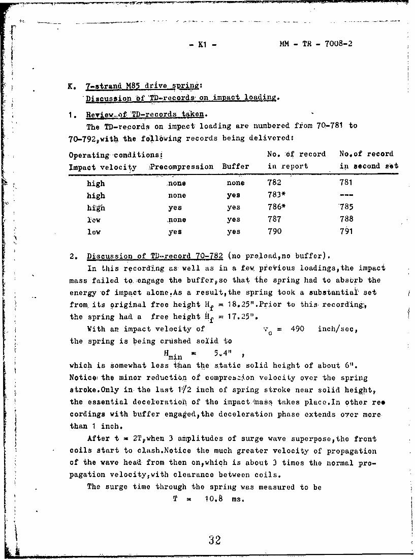
1. Review-ofTD-records taken.
The TD-records on impact loading are numbered from 70-781 to
70-792 9with the fo11owing records being delivered:
Operating conditions: No. of record No.of record
Impact velocity iPrecompression Buffer in report in second set
high none none 782 781
high none yes 783---
high yes yes 786* 785
10ow none yes 787 788
low yes yes 790 791
2. Discussion of TD-record 70-782 (no preloadno buffer).In this recordi;ng as well as in a few, previous loadings~the impact
mass failed to,.engage the buffer~so that the spring had to absorb the
energy of impact alone.As a resultthe spring took a substantial set
from, its original free height If = 18.25".Prior to this recording;,
the spring had a free height Hf = 17.25".
With an impact velocity of v 0 490 inch/sec,
the spring is being crushed solid to
Hmin " 5*4"
which is somewhat less tihan the s~tatic solid height of about 6".
Notice the minor reduction of compression velocity over the spring
stroke.Only in the last 112 inch of spring stroke near solid height,
the essential deceleratioA of the impact imaýs takes placo.In other ree
cordings with buffer engagedythe deceleration phase extends over more
than 1 inch.
After t = 2T~when 3 amplitudes of surge wave superposethe front
coils start to clash.Notice the much greater velocity of propagation
of the wave head from then onwhich is about 3 times the normal pro-
pagation velocity~with clearance between coils.
The surge time through the spring was measured to be
T 10.8 Ms.
32

MM - TH - 7008-2
3. D&acussion of TID-rEcord 70-78J3 (high,.u preluwsdbut with buffor).
Here the free height h.[d been further redticeei ity xet~ii,'htu 1b.91.
With atn impact velocity v 0 481 °inc/dc
the spring comes down to It - b.l" I
which im itbout the solid height of the spring in st.utic tosting.
The main decelerntion of the impactt mass is performed by the addi-
tionuil bufferwhich is compressed over 1.65" strokewfrom Ii n 7.75"
to H min b.1".Notice the more graftuisl decelertrtion of the spring
end in this record am compared to Tli-ri'cord 70-782 without buffer.
Againthe coils start to clush after t - 2Twhen the amplitudes
of 3 waves superpose.
The surgo time per coil of the wave head (first transition)
vns measitred to be
T1 .235 ms/coil
ie.o,about the same its in TD-rec!5rd 70-782.
The entire surge time through the spring im found to be:
T - 11.7 ms.
4. Discussion of TD-record 70-786* (highwith preloaid).
Hero the %pring was procompressed from a free height Hf - 16.90"
to an initial height I - 14.5"
With an impact velocity v° 474 inchbec
the spring coils at the rear end go practically into contact after
t - Tbut without clashing.The ttme for the second transition of the
wave head is slightiy less than the time for the first transition,
indicating coil contact here and there.
The wavehead returns to the front end of spring near the end of
the compression stooke and then the front coils clI&shts indicated by
the much steeper wave frontrwhich is visible up to about t = 2.5.T.
Aguinthe spring reaches pranticnily solid heighitwith 11,n - 6,05".
o During the first transitiontho surke time per coil of the wave
head is measured to be T1 - .209 ms/coil
This vilue is distinctly less than for the records without preload
The surge time for the entire spring is measured to be:
T * 10.8 ms
/#,vaiCopy
'k)

-K3 MM T 7008-2
5.. Discussion of T)-record 70-787 (low,no preload).
Here the impact velocity was reduced to
if v0 396 inch/sec.
With Hmin = 6.40" ,the spring does not quite reach solid height.
Here the wavehead returns to the front end of spring prior to buffer
contactwhen the rnompression velocity is still substantial.After ;
g t = 2Tsome of the coils clash slightly during the third transition
of surge wayeas indicated by the shorter transit time.The wave head
is visible up to t = 4T.
During the first transitionthe surge time per -coil is found to he-:
1248 ms/coil
i The enti-e surge time through the spring is measured to be:T = 11.1 Ms.
6. Discussion of TD-record 70-790 (low~with preload).Here the spring was precompressed to 1i = 14.5"1
Sfrom a free height Hf = 16.9"1
With an impact velocity of 415 inch/sec,the spring reaches a
height Hmin 6.40" pslightly above solid.
After t = 2Tthe front coils clash~as indicated by the much steeper
wave front.The wavehead is visible up to t = 3T- .
During the first transitionthe surge time per coil of the wave
head is TI = .223 ms/coil ,
which is again less than the corresponding value under no proload.
The entire surge time was measured to be
T = 10.5 ms.
a

- LM- M-TR- 7008-2
L. 7-strand M85 drive sprina:
Discussion of TD-records on sudden release of spring.
1. Review of TD-records.taken.
A total of 6 TD-records was taken and delivered as follows:
Operating conditions: No.of record No~of recordPra-31ad Support of rear end in report in second set
high rearwiard only 793* 794*medium rearward only 795* 796*medium fixed both ways 797* 798*
All TD-records on fast film.
2. Discussion of TD-record 70-793*.Sere the spring was precompressed to an initial height
H2 = 9 inchesas compared to: a solid height of 6.2".More accuratelythe level of
precompression is measured by the pitch of the coils~which was found
to be 112 = c202" over 40 coils.
Here the spring had still the original free length Hf = 18 .26",or
hf 03 9 8 i' per coil
since these sudden release tests were conducted prior to the impactl!oading tests.This means an initial deflection per coil
f2 0398 - .202 .196"
The front end of spring (released end) is found to extendat a constant velocity Vo 79 inch/sec.
The rear end lifts from its one-way support at a time
t = T a 11,55 ms
after the sudden release of the front end and then also assumes aconstant extension velocity vf same amount v
taThe spring then bounces out between two stops.The superposed dis-.
turbance originating from the roar end at time t = T is due to thewave head flattening out from its original step-formo
35

-L2- M - T -7008-2
3. Discussion of TD-record 70-795*.
Here the spring was released from an approximate height
H2 = 12 inches .
More accurately~the level of preload was measured by the pitch of the
precompressed coils: h 2 266" over 40 coils.
With a pitch at free height hf = 0398",the deflection per coil in
the precompressed state then follows to be:f398 - .266 L132 "/oil.
The extension behavior of the spring is the same as when released
from a higher preload.Jlere a constant extension velocity
v = 543 inch/sec
was measured.
The separation time Ts of the rear end was found t, be:
T 11.2 insS
4. Discussion of TD-record 70-797*.
Here the first and second end coil (this spring has open ends)
were clamped to the guide rodso thie number ol active coils was reduced
by at least one coil to about 44 coils.
Here the pitch in the precompressed state was
h2- ,263 "/coil over 40 coils
iLe.,an initial deflection f 2 135"'2IThe free end uf spring is found to extend with, a constant velocity
= 562 inch/sec
The spring performs a periodic vibration with the period
4T - 49 ms,
or T 11.25 ms .
oC,•

-M1- MM- T- 7008-2
iM. 7-strand 20 mgm un drive spring:
Discussion of TD.'records on impact loading.
1. Review of TD-records taken.
These TD-records on impact loading are numbered from 70-701
to 70-7201with the following records being delivered:
Operating conditions: No.of record No~of recordImpact ýreiocity precompression in report in second set
hiigh none 709* 710"
high yes 71 2*. 711*low none 714* 713*low yes 717* 716*low ye3 715*TDR 70-715* is an odd record1where the precompressing means of springwas released slightly prior to the actual impact of the mass.Nte : All the records delivered were taken at rather low magnification
q - .229x , or 1:4.37 reduction,in order to accomiodate the entire length of spring (Hf = 29.3")within the film width of 8".ThereforefiLt film had to be usedinstead of conventional photo-recording paper..
2. Discussion of TD-record 70-709*(high,no preload).With a heavier impaict mass 'of 3.25 lbs and an 'impact velocity
o at =535 inch/secthe spring reaches a minimum height
Hmin V. 1.1.6" m
as compalred to a solid height of about 8.5".Thereforethis strongspring is capable of stopping the impact mass of its own and no addi-tional buffer was installed.
r, When the wave head reaches again the front end of spring at time
t w 2T ,the compression velocity is already much reduced and th6 third
r! wave amplitude superposed is much less than that of the wave head.The coils come close to solid,but do not clashas indicated by theSthird transit time being of normal length.After t x 3Thoweverithe
rear coils cla,.hpas shown by the much steeper wave front.The wave headis visible up to t = 4T.
During the 4?irst transitionithe surge time per coil of the waveheadwas found to be, TI - .455 ins/coil ,
with the entire surge time T = 17.6 m8.

S-M2- MM - TR - 7008-2
3. Discussion of TD-record 70-712• (highpwith preload).
Here, the spring is preloaded to a height , = 24.1",yas compared to
its free height Jif = 29.1" (5" deflection).
Wtth an impact velocity v - 554 inch/sec ?
the spring reaches&a height Hmin 11.3 inches ot A few rear coils clash already after t z T and the front coils ciash
Saiter t = 2Twhen 3 wave amplitudes superpose to the prelood.The wave
head is visible up to t - 3T.
The surge time is measured to be: T = 17,$ ms
4. Discussion of TD-re. rd ZOIl4* (lowcno preload),
Here the impact velocity has been rd1uced to
Hrtv° = 402 inch/sec.
Here the spring is found to stop the impact,,mass at a minimum:heightH - x 16.3 inches
which is way above its solid height of about 8.5 inches.
The coils never clash during their response to impact and the wavehead
is visible up to t = 3T.A The surge time is-measured to be T = 1 8 ,1 ms.
5. Discussion of TD-record-70-717* (lowwith preload).
Here the spring has been precompressed to a height
HI 20M4 inches ,
i~e.fa considerable initial deflection FI = 8.7" from its free heightI of 29.1 •1of 2,{th an impact velocity, v° 408 inch/sec,
the spring reaches a minimum height H 14,i3 inches.
The wavehead reaches the front end of spring at time t = 2T,when
the compression velocity is about O.No clashing of ,coils occurs and
thewavehead is not visible after t = 2T.
The surge time is read to be T = 16.9 ms
i.eoedistinctly less than in record 70-714* without preload.
ii

C - -• .e -• .. .. • ;" '- t• " - • .. ''- 44- , - .•-
-N1 MM -TR -7008-F
N. Attenuation of.,single surge wave in stranded wire spring.The impact of a'mass. on a spring generates a single surge wave
¼ •with an infinitely steep wavehead.Both the velocity v a. the potential
u of the end coils jump suddenly from 0 to a certain va ,e vo"
Diagram 4 on page 'Y8 of Appendix Y illustrates the -elocity
distribution v(xt) over the length L of the spring at various
instants of time t = 0 9 T T/2 9 3/+.T , and t - T.The potenQialdistribution -u(xvt) is similar.This diagram illustrates in a general
-manned' the change of the wave shape during the first transitionthrough the spring,as shown lby all the impact records taken.Thia first
tranaidion of the impact wave through the spring is best suited tostudy thle basic attenuation behnvior,since the wave propagation isnot disturbed or camouflaged by wave superpositions as yet.
At time t = ,Othe wavehead. is entering. the spring with a vertical
steppas indi6tted by the dotted line v(xO),At time t = T/4,th'e peak of the wave ,has reached the quarter point
x =-L/4,while the wavehead is already at x - .275.L aind the stephas changed into a steep slope.The spring coils withý;n this slope, are still- being accelerated.
.At time t = T/2,the watve peak has reached the half •point x = L/2.J Tihe head of the- ave is at x = .55.Lpthe slope of the wavehead has
decreased and the wavehead comprises now more coils still beingunder acceleration.LA ns the wave progresses furtherpthe wave head comprising all thecoils still under acceleration gets longer and: -longer i as the distri-
lbuttons at t .75.T and T show.The beginning of the wa-,,ohead hasa shorter surge time than the wave peako.g.oin Diagrami 4.
U• Th = .91 . T
Thereforewe must clearly distinguish between the surge tinme of, the wave 'peak (T) and the surge time of the wavehead (T11)9The sameý
applies to the surge -imes- per coil,TI and T1h.The surge time per
coil T listed on all the records and evaluated therefrom is actually
..the surge time of the waveheadbut the second subscript was omitted
for simplicity reasons.
.39

L7- N2-
Reproduced frombest available copy.
The smoothening-out of the wave front. durihg propagation is
typical for all stranded wire, springs.This -jahavior has already-
been observed previously on single wire springspbut to a much lesser
depred.It is caused by the dampinig inherent in the spring and is a
-welcome featuregsince it aids in distributing uneven impact loads
*more and more evenly over the length, of spring,so thiat all the coils
-share about equally well in the total deflection of the spring.Befhivior of -wurie ;aves after the first.ttansition:
After the first transitioutseveral single surge waves superpose
* in the 'spring.However#the wavohenad is viiible in the 'TlD-recurds
* oger a length of -time, from 3T to AT.Under proloadtthe, wavehead
disappears faster,•aftr from 2o5T to '3T.
t' rF or •sirg ', wir'e springs it has been found previouslyttha.t thew vwvehead is disc~irnible *over 6 *t[o 8 surge times Tqdue to the lesser
Avdomping inherent in those springs,
On the other handit might be inontioned herefthat in highly damped
- rrig springsr the wavehead can. only be distinguished up to about 1.5.T.
Therefore~with respect to wave attonuationgstrandod wire springs lie
somewhere in the middle between single wire springs and ring spzvin~s.
Quantit:.tivo ineasurement of .daur i-,:V •The a-bove statumeat, about the attenuation %of surge waves in
strauded wire springs are largely of a quulitative natureolIi order
to arrive at a quantitative criterion. or indicat0ilstiad'ard tests
should be defined for determining the degree of dajiiiig:
EE.g.,for atsuddenly r~eleased spring with rear end fixedcthe decay
of the amplitudes in compression and extensioln could be measured
and a dwiipink- cunstant could be derived therefrom.Howeverysuch
standard tests and methods are not established as yetpnot. even foer
highly damping spring types as the ring spring,
tW
F
I.

I01 MM- TR- 7008-F
"0o Comprarison of' measured and. calculated surge. times TOne of the major objectives of this study is to obtain
"realistic formtlas -for stranded wire spriiis and to establish thedifference in d-ynamic- resaonse -as compared to single wire sprilAgS.For the liattor,a complete set of formulas is available since 20 years.aid these f6rmulas were well proven by many TD-recordings undera variety of operating qondition.i.
Calculation of.. surg•e times T,
Tble II on page Y2 of Appendix Y lists the surge times T .of the5 t•,t sprints as alculatod und'&r two different assumptions:Assmuption A : The spring rLt6 I is *the ul•j:ebralic sumn of the rates.
of the component sir;le wire sprin.gs.Assut.p-tion B : The "i itial •lpri,•g rite" of thu measured force-
deflection diagram P(lV) [Linear portiun] has been used.According t 9 forimila (26)ý,the surgO ii.me T increases i _[1Pro1utien
to the squpre root of th.e spring r"Le R ..........
T, 1
Thereforegit must be expectedlthut the surge time T will decreasewith ifrerasinig levels of spring compression.
Measured values of surge time T :Table III on page Y3 of Appendix I lists the operating condi-tions
for 40 TD-recordings of im,:pact loading of the 5 test springs.These.data show the intensity of impact ill terms of the initial deflection-per coil, f, ,and impact velocity v.
The meaŽsured surge times from these 40 im.pact loadings its well
as farom 18 sudden release tests are compiled irn Table IV on page 14of Appendix Y.
Those measured data have also been plottOed ill Chart I on page Y5
of Appendix Yfor best visual illustration of the resuLts.Tlis Chartis well suited to determine th}e influence of various parameters,e.g.,
level of impoct velocity , 9
preloid versus no preloadF sudden release testis, versus impact loaiding.
L41

rd-02 - MM- TR - 7008. P
SIfluence of. the impact velocity level on surye time:
"[ 1t appearsv,that in most cuses• the surge time T is slightly
-greater with the lower impact velocity than with the higher one.
lovevergthis is not absolutely conclusivetsinc6 the differences arequite small and also erratic.This uncer-iainty is quite plausible,
since the 2 leveýs of impact, velocity vo are not vastly different
(see Table III for operating conditions),.Recordings.at rather diffe-
rent veloc!iy levelspsay 100 9 300 v and 500 inch/sec are believed
to shed mare light on the infl-uence of vo on the surge time T.
Influence of •h. preload versus no preload:
Chart 'I shows 6learlypthat the surge times T decrease with
increasing preload and compression leveloThise results confirmii
formula (26 s With increasing preload~the average spring rate alsoincreases due to the progressivegnon-linear force-4aflection cha-
racteristicspand a shorter surge time T must be e.:pected'o
".Sudd-2n. rdlease tosts verkus impact loadings:
With the 3 springs testedkthe surge time T in sudden release
was ailways found to be a few percent higher than in impact loading.
This result iN also quite plausible:In exteiisionithe direction of the
frictional forces is reversed as compared to compression and a lower
force-deflection' oharactoristics P(F),with a lower rate R',results.According to formula (26)pa -longer surge time T is then to be expected.
Co omrisorn of calculated-and measured values of T:
In Chart lpte T-value calculated under atisumptioti A is indicated
by a dotfed line and the T-value kbsulbing from assumption, B by asolid line.
'The T-values (A) agree well with the measured values for the two3-wire strand springs,but are substantially greater than the measured
values for the 3 7-wire st'anL, springs.The T-values (B) aigree fiirly well with the measured values for
all 5 springs.Only with the SPIW-7 and M85-7 springspthe measuredvalues with ,preload lie still below the calculated values and suggest,that a still higher spring rute than the initial rato should be usedfor closer agreement.
- ' -2

-Fl NM -THt-7008-F
V
* P. Compafison of measured and calculated extension velocities v
in sudden release tests.
Againtthe, objective is to establish a formula. to predict the
edxtensionvelocity vo in sudden ricase froiii the given precompressioti,
for stranded wire springs in particular.
Measured values of extension velocity:
For 3 test springs96 TD-records each were- taken in sudden release
of spring,with 2 records for each operating condition.It was found,
that the extension velocities of these 2 records varied very little.
In Table V on 'page YO of Appendix Ypthe average extension velocity
v 0 evaluated from these 2'i cords is listod9 The range is
" * from 41o to 831 inch/sec
Furthermorepthe inivial deflection per coil, fS • of the precompressed
springs is also given in Table V.
Calculated values of extension. velocities:
Here the formula o f2 /T(.. ' . SC ' T (28a)
was used.T. depends on the spring rate R.Againpassumptions A and B
are made and the T'1-vluos obtainad under these assuuiptions are also
listed in Table V (top).Finally the v° - values obtained from above
formula 128a) are given in Table V.
Comparison of measured and calculated values.
In Table Vpthe ratios of measured 'to calculated velocity are alsolistedoFurthermoreý,for best ,vist.akj i'llustrationtthe vo-values have
been plotted in Chart II on page Y7 of the Appendix Y.
With the 3-_ire strand Si'IW springpthe measured velocity vO is
about 5%_ less than the value calculated by either method,A or B.
With the two 7-wire strand springsonly the method B gives good
agroenoent:Here the measured value vO is 1.3)% and. 1o3M higher than
the value calculated under assumption B.This latter result is quite
plausible:Due to the progressive characteristics P(F),the precompressed
spring contains actually a higher potential energy than indicated bythe initial spring rate R.
43

- i1 -~. ".MM -TR- 7008-F
oSumar- of matior conclusiOns.
1. Orgunisa tivn of Final Report..
The text. of this report has been supplemented by data and illu-
strations in 3- Appendices:
Atpondix X gives basic spring data in the form of data sheets and
measured Force-deflection diagratms (given data).
Aimendit. Y give* the summary of both, calcuhlted ttnd measured spring
response data in bos! tdblllr. and graphical form.
Appeadix Z contains 30 samples of time-displaceinent records (alto-
gether 60 records taken and, evaliat.ed) and because of
its volume is submitted in a separate cover.*
2. Comments on shrini, rates.
Stranded wire springs are found to, havo a non-linearprogressive
force-defloction characteristics P(k),pis illustrated by the measured
P(F)-diagramn 1 to 3 in Appendix X.
It appears proper to distingui-sh between 3 force-deflection rates
a) The measured initial iatep-a:s defined by the lineai initial portion
of the diagramtover the first few inches of stroke.
b) The ,mesured average rate for a certain stroke extending well into
the progressive portion of the diugram.
a) The calculated ratge,culculabed under the simplifying assumptionp,
that the- tOtl. rate is the algebraic sum of the spring rates
of the single wires in the straud.
From a comparison of these Tates it was foundthat even the
measured initial rate is always higher than the calculated rate,
showing an incriease of atr few percent for a 3-strand spring, andincreases up to 20Y for a 7-strand spring.With lurge deflectionsclose to soli. hoight,the measured eaveruge rate is increased by
still larger percentages,
S3.lBasic behavior of surge waves.1n1 gener l,•stranded wire springs were found to respond to dynamic
loading (impact loading or sudden release) in the same fashion assimile wire springs.The surge waves generated travel through the
spring at a constant surge velocity und also superpose in the same
manner as known from siliple wire springsHoveverothero are alsomarked differencesas the nxt paragraphs will show.

Q2 -M - TR- 7008-4F
4. Influence of the deflection or proload on the surge volocitv•- •In single wire springs with linear spring ratepthe surge velo-
city c- was found to be the-same for all levels of spring compression.In the stranded wire springs testedphowever•th- surge velocity wasfcand to rise slig.htly with higher loads and deflections.This resultis quite plausible from the theoretical viewpoint : The theorypredicts that the s utrge- velocity increases in proportion to thesquare root of the spring rate R.
5. Smoothenins, of the w.vehend.Iu a. stranded 'wire springthe initially infinitely steep slope
of at single surge wave generated by impact w•ill decrease in transi-.tion and -will svrecnd over sevokal coils, by, the time the, waveheadreaches the rear end of spring.This response is due to. the meachanicaland friction 6oupling bet-pen the wiro-s of T'he strand and' is much morepronounced than in single wire springs.
Due to this behaviorpthe surge timeo of the wavehead '(firstresponse) is shortor than the surge time of the .:ave peak (whorethe wave has reacned its full amplitude).Therefore,it becomesnecessary to distinguish 'between these two surge times.
6, Dissin,)varance ,u the wavehocad.In the TD-records on impact loadinglthe wavehead is visible over
a time •poriod of from 2T to 3.5.Tafter ini~intionoThiis time period is much, shorte'r thain with singlewire springs of comparable length and surge time,where the wavohead
is discernible up to 6T or 8T after initiation.This behavior is caused by the pronounced smoothening of the
wavehead during fransition due to hogher inherent damping.Thisresponse must be considered favorable and desirabletsince it aids,in making all the cols to share apbout _:!u n the total deflectionoT-the spring.Tho pcak strus4 is thus kept as low is possible,resulting in longer spring life.
I = = :: % ..

Q3 - Mk - TR- 7008-F
7. Formula for surgo-. time and surge velocity.
In the. surge time formulas (11) and (12)' for single wire springs,the wire diameter d, and' the mean coil diameter D, enter as the majorindependent variables.
For stranded wire springsit has been found more practical to usea '16ss explicit formpbocause of the more complex configuratiun.'In formula (26)-ithe active weight W of the spring and its rate Renter tS independent variables~ra,,',ier than d and D.Here the questionariseswhich one of the 3 spring " tes listed in Paragraph Q2 abloveshould be used in order to arrive at realistic valuey, for the surge.time T
This question was decided by the comparison of measured surgetimes (from the TD-records) 'i~th Calculabed surge times (using dif-ferent values f~r It J1t vas found that the measured. initial rate
-gives rather good agreement ,between measured and calculated surge"t4bimes T.There is some indicut.iui,'tqhui sometimes a still highervwlue of R (,toward the muwsured average rate) would improve the-agreem~it.See Chart I in Appendix Y.
8S. `Foihii,ýIa for the extension volocity i.i sudden release.
According to fdrinuli (28) and (28u),pthe oxtension velocity vOis Aieoctly proportional to the precomipres;-ion ats expressed by the initialdeflection per coil, f. land inversely proportoinal to the surge
time per coil, TI .Again i0he question arisesby which spring rateRthis surge time per coil T1 should be culculated.And aga in .it isfoundpthat fair agreement between measured and calculated values ofV is obtained by using the m,,,sured inlial spr'ini rate RoA higher0*sp.'ing rate towar(t the meatsured aver,age rate wuUld still improve thisjagreement.
9. Formula for induced, lotid or fo-.,ce.Here formula (.9) applles.Judging from tile above results~again
the intial measured, spring rate R should be used for close results.
Of courselsince no dynamic ,frces were measured, there was no directcomparison possible.Howevervwhen calculating the force from themeasured deflection in the recordspfair agreement was reached again.

-04 - -TR- 7008-F
, Repr,'duced frombest, available copy.
10. Comments on the time-disllacetent records.
It was found more d2ifficult to obtain good recordings on these
5 stranded wire springs than on single wire springs recorded pre-
4viou•!•%On the one hand 1the thinner wirespwhich also, lend a much shor-tPr
length of wire suitable for light refl-ectioumust be expected to
give a loss intens-e and poorer image point than the coil of a single
wire spring.
On the other hand~due to the, great length of some of the springs,
the recordings -had to be made at reduced scalifrom about .25x to .40x.
In certain casos~especitally with the 20 mm-7 spring and al-so insudden release rucording,fast film was used instead of the slower
photo-recording paper.L In generalpthe records obtained show many fine details and the
results evaluated from them confirmed the aLbove drawn concj.usionas
again and agamii.Thcse records contain a wealth of information and
may still be ovalua-ted firther with other objectives in mind.
Special attention was given to compriehensive and thorough reportingof tile operating conditions for eachi rocord,to make -the evaluatod
resul ts most men 1ningulFuthrmle•heevlaton o imesoveloci ties, etc. pwere per-
formed as accurately ia possibletin order to bring, out the sometimnes
small but still definite differences in dynamic resp~onse to thatof single ,wire springs.
4 7
!

-1Ri- H- TR- 7008-FE -
R. Recommendations.
1. Influence of the compression level on sur•,e velocity.
This influence could be checked -out over the Tull compression
range by specially devised test recordings:
Only 7-strand springs need be used,since they show the niest pro-
grosnive P(F)-diagram.Here the test spring would be precompressed
to various retius f1/fs - 0 9 .25 y .50 y .75 and thd'spring would
be given a Ii d compression stroke by, impact of less than 2Tduration (to aevoid more than 2 wave superpositions).The impact velo-
city would be lowsay about 120 inch/sec.These records would then beevaluated. regarding surge time/coil of the wavehoad and wave peak.The results would reveal the dependency of T and c over the fullrange of cpmpr.ession level.
2. Quantitative measurement of dampinao
Special. tests are to be devised and recordi)ngs made to establisha quantitative measurement of the damping inherent in a spring.E.g.va very light impact mass (us light as the spring or lighter)
,would be used and both the impact velocity anir rebuund velocitywould be ovaluaTod in order -o determine the meachanicai efficiency
rate47v01/ \02 3)
Or the percentage of actual damping to critical damping could bedetermined from a free vib"ra ion.
3. Attcenuation of wtives in other media.In order 10 obtain a full qualitative understanding ?f the atta-
nu;:tion procu2ss in a linear modiurr and also to arrive at some simpleformulas for qualntitative damping,tho propugationk of impact wavesshould also be recorded for other dpmnping springs and materials,such as- a Poly-Urethane bara stack of rubber discspa bar of hi-dampxiliconoe tc..
Dr, Karl W Majier

-Xi- 1NTit7008-F
A PP E.N DIX X
Basic sp.-ini.- dii 6,1 Page
Data sheet on 3-strand SPIW dtrive sprino x
Data sheetj on 7-strand SrIW drivu spring X2
Diagram I Measured forco-ficfit-c-Liun. ditigrun P(El-~ X3~ui SPIW drive s;)raiL,-s,3- and, 7-st:,ra~nt
Data. sheet on 3-strwnd .M85 dIrive bpring X4
Data Shee~t oi, 7-stritud M85 Crive spring X5
Diagram 2 Me~Iasured force-6-flocot~io diagram p(p) X6-on 'k,85 drive s prin ji,,z 3- and 7-s triindI
Data sheet on 7-stren(! 20 mmi gun (Irive sprint: X7
Diagram 3 : Neasured force-doefloc Lion cdi",-ra. 11(F) X8On 20 mm gun -ildrive sprii'jlýp,7,~ tr~aaL(
Ii

SX1 - MM-T- 7008-1
Basic data on SPIW drive spring,3-strand wire.
Drawing No. : AAItNo.97384,B53099-10096.
Material music wire
Wire size# d 9034
Strand. diameter, d* (reference) 0073
Outer diameter of coils, D0 (measured) .451
Inner diameter of coils, Di. (measured) .317
Mean coil diameter, D .384
Diameter of inner guide rod 11O0
index of coilsp C = D/d 11.3
Type ,of spring ends closed
Total number of coils, Nt 76.5
Number of active coils, N 74
Free height of spring, f 177014
[H•f did not change during test programno settin&]
Length of 60 middle coils (60.hf) a{'L. I'ee height H f 13.86
Average pitch at free height, hf .231
Approximate solid height, H 5.7
Force deflection rate, P/F P in lbs/inch:
Calculated from standard formula 1.38
Measured over the first 5" of stroko (also by drawing) 1.40
50

-X2- MM- T- 7008!1
V61 Basic datia on SPNWdrive sprin&.coiled from 7-wir, strand.
Material ibusic wire# QQ470
Number of outer wires 6
Diameter of outer wires, d .°026
Diameter of core wire .029
Diameter of wire strand (reference) .'081+
Outer-diameterp Do , measured .442
Innerdiamoeer, Di v measured .278
Mean coil diiameterp D .360
Di'ameter if inner guide rod in testing .266
Spring index of outer wires, C = D/d 13.85
Type of spging ends closed
Total number of coils, Nt (after testing) 60.5
Number of active coils, N. 58
Free height Hfbefore and after testing 14.26 / 13.80
Length of 50 middle coilabefore and after testing 11.90 / 11.65
SAverage pitch at free height, hf , .238 / o233
Approximate solid height, H5 5.3
Force-deflection rate, P/P ,in lbs/inch:
Calculated from formula 1o85
Measured over the first 5" of stroke 2,10
I,: 51

*1f0~1$
AA~ Az-
.T I
zV 7
7- 7- ~.~;;.;: ~ ~ :':: ;~:i I
- 4 . - - V ½ jV . g , ~ *
- ,.~g.- - ~fr-,,-~.71
'P~~~~ *. - * 4 'V
.. - .-. ~-1 ..7 I~ p
L", It 1
44,I~

-X4- MM - TA- 7008-2'
Basic data onjM85 drive spring, coiledfrom. 3-wire strand.
No drawing of springall dimensions ineosurod.
Wire diameter0s d .065
Strand diameter, d* ((rcference) .14u +
OUter dinmeter of coils, D (average) ,.700
Inner diaimeter of coils, D .4 20
Mean ceil diameter, D .560
Diameter of inner guide rod 075
Index of coils, C a D/d (husky spring!) 8.62
Type of spring ends closed
Free heightp 1lf fbefore and after testing 18.30 ; 18.20
Total numbr of coils (ifter testine)v Nt 44-5
Nmnber of a.ctive coilsp N 42Length of '10 middle coils ,l•.l, = 1 0o4 / l'6o76
Average pitch at free height hf 421 / .419
Approximate solid height, 113 6.8
Fu-ce-dufloction rate, P/F 9 in lbs/inch:
Calculated from formula 10.45
Measured over the first 5" Of stroke i i,',.•
5
53

t ----5---
'Basic daaol"&diesrn.-tad
Spring drawing : Springfield Armory' B 7791254
Material Spec MIL-W-13604 : FS 1085A
Number of outer wires 6,
Diameter of outer wires, d o038-
Diameter of core wire, pd .041
Diameter of wire strand, d** {eforence) ,117 +
Outer diameter of coils, De (weasuredlarter testing), 650
Inner diameter of coils, Di (measured) Q410
Mean coil diameter, D .530
Diameter of inner guide rod .375
Index of coilsp C = D/d (outer wires) 13.95
Type of spring ends plain
Total number o1 coils, N% (after testing) 45.4
Number of -active coils, N 45
Free height, H. ,before and after recording tests 18 26 / 16.90 !
[Spring set ,considerablypartly due to impact compression to isl
Length of 40 middle coils at Hibefore and after tests 1'5.92/15,04
Average pitch at free height, hf 1398/.376
Approximate •solid height, H 6.2
Force-deflection rate, P-/F gin lbs/inch:
Calculated from formula (sum of single wire springs) 3,29
Measured over the first 3" of stroke 4.0
.7 7

040
Jh4:~ -X- N4-TR-708-2 4k
MuEdt:f401h.._
- 4 J -
~IIH IT I.,
j4 -4-4-
J __--i I t :f
t CF4 4
_ ~ ~ ~ - t ~ tr~t-
1, :ijIr~1- _
ti
+-T4
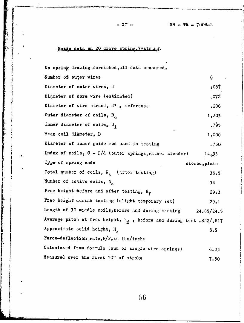
- X7- 'M -TR -7008-2
Baxic data on 20 drive suring.7"strand.i
No spring drawing furnishedall data, measured°
Number of outer wires 6
Diameter of outer wires, d 4067
Diameter of core6 wire (estimated) '072
Diameter of wire strand, d* ., reference .206
Outer diameter of coils, D0 1.205
Inner diameter 0f coil's,, D. .795
Mean coil diimeter, D 1.000
Diameter of inner guide rod used in testing .750
Index of coils, C = D/d (outer spkiigsyrather slender) 14,93
Type-of spring ends closed,plain
Total number of coils, Nt (Ufter testing) 36,5
Number of active coils, Na 34
Free height before and after testing,, Hf 29.3
Free height durinh testing (slight temporary set) 29.1
Length of 30 middle coilspbefore and during testing 24.65/24.5
Average pitch at free height, hf p before and during test ,822/.817
Approximate solid height, H 8.5
Force-deflection rateP/Fyin lbs/inch:
Calculabed from formula (sum of single wire springs) 6,25
Measured over the first 10" of stroke 7.50
. •_ ...... -- %'• i l II i I5 6

~FPt
- 1~.F
14 1t-fI 4- $1-r
J J
*~ ~~~ 7~ 1 7.fP-. 4
tV

-Xi- MM -TH -7008-F
A { APHPEN,) iX .
Additional Spring -Data,
Data. ,valuated from the TD-records or calculated .from Theory,
Table I : Length of wire in coil , L1, ,for 5 test springs
Table II : Numerical calculation of surge, tinfes and Surge velocitybused on two alternate assumptions
Table III : Sunmary of operating Conditions in impact loading tests
Table IV : Compayison of surge timespmeasured and ialculated
Chart I : Surge time T p measured vs calculated, wvalues
Table V : Sudden. release 'tests:Comparison of calculated and measured extension velocities
Chart II : Extension velocity v° ,m~asured vs calculated
. Diagram • :• Attenuation ,of wavehead in first transition
58

- - MM- TR- 7008-F
T,09 I: Length of wire in coil. 1 ,foi 5 test, springs.
Spring SPIV-3 SPIW-7 'M85-3 M85-7 20mm-7
Wire diameterid .034 .Q26 .065 .038 .667S.Mean coil diaD ,384 .360 .560 .530 1100
lndexy D/d 11.3 13,85 8.62 13.950 14.93
Circumf.,, t .2--ý'4 130 o1,757 1.662 3,142
Free pitch~hf ,J31 .238 .421 .398 Q822
1, + (hf/Ii D)V i.037 1.057 1,.068
, 1.018 1.022 1.028 1,028 1.034
This is relntive lagth of coil ho-Lix centerlinepcompared to ;.D.
Absolute length ofcoil helix CL 1.225 1.155 1.807 I '71 3,25
No. &.t turns/coil 10 16 7 15.4 17
length of layb ,367 ,434 , •6b2 1.15
Radius of s,,irala .0195 .0275 .0375 .0395 .0695
circumf., 2lta .'123 .17D o235 .248 .437
length katiop*/b 1.054 1.076 1.045 1.068 107
Length L of wirein one clil 1.290 1.243 1.89 1.823 3.48
length ratio LI/1TD 1.070 1.10 1.075 1.097 1.108
i, ,
' A IK. :2i

MM -TR- 7008-F
Table II : Numerical calculation of surae times and surge velocity,
based on 2 alternate, assumptionsR calculated or megsurod.
Spring SPIW-3 -2SPIW-7 M85-3 M85-7 20mm-7
Wire diameter, d o0;i4 A026 .065 .038 .067.029 .041 .071
Area A = .785.d 2 .00091 .00053 .00332 .00114 .00,353600066 o00132 .00396
Area A of strand .00273 .00384, .0100 .00816 .0251
Length of coil, Ll 1,290 1.243 1.89 1.823 3.48
Weight of Coil, WI .00099 .00135 .00,535 .00421 .0247
Number of active coils 74 58 42 .45 34
Active weight W = N.W1 .073 .078 .225 .1895 .84
First assumption: (A)Spring rate R calcul. 1.38 1.85 10O45 3.29 6.25
Rate per coil, R1 102 107.2 439 148 212'5
Surge time/coil,. TI,ms o1585 .18,1 .178 .272 .550
Surge time T = N.TI,ml 11o73 10.5 7.47 12,23 18.7
Surge Veloc. c w LI/TI 8,140 6,870 10,620 6,700 6,330
Force : 6P/v =,-R1 T1 .01615 .0194 .078 o0402 .117
Second assumption:1(•)
Initial rate- measured 1.40 2,10 11.20 4.00 7.50
Rate per coil, R1 103,6 121,7 470 180 255
Surge time/coil, T1 9157 .1695 0172 .246 .501
Surge time T = N.T1 11.6 9.83 7.20 11606 17.05
Surge veloc. c = LI/T- 8v210 7,340 11,000 7,400 6,940
Force: AP/v = R1.T1 00163 .0206 .0805 .0442 .1275

-3 -MM T - 7008-F
Table III: S ummarl of operating conditions in impact- loading tests.
. (Number of TD-recordlimpact velocity vogfree pitch hfpand fl).
SPIW-3 SPIW-7 M85-3 M85-.7 20.m-7
"W = 1.,15 lbs W - 1.15 lbs W - 2.15 lbs W m 2.15 lbs W - 3.25 lbs
722 475 743. 485 763 480 782 490 709*R 535
,231 o232 .421, 6,384 .817
7232 478 7448 480 764*R 473 783-9 481 710* .553
.231 p232 .419 ,376 .817
725R 465 745 4,92 766 495 785 521 711* 564
.231 . .232 .,419 . .' o376 .817
.055 .046 .061 ,050 .191
726 465 7462 485 767*" 494 786*R,, 474 712*" 554
o231 .232 .419 .376 .817
.053 .047 .043 .056 .147
727 . 314 747 300 768 390 787H 396 713* 380
231 -.232 .419 .376 .817
7288 317 748B 315 769R 382 788 403 714*R2 402
,231 .232 .419 .376 .817
730R 322 749R 335 770 359 790H 415 716* 400
.231 .232 .419 .376 .817
.056, . 054 o074 .051 .253
731 308, 750 325 772"R 420 791 409 717*R 408o,231 , 232 ,.41 9 o376 . 817
.055 .050 ,o0045 o051 •.256
781-no buffer 715*-odd record
7828-no bufferJ
"r t1

-14- MM - TA - 7008-7
T.LE I,,V Cs pErivon of surgeo times TS and T.mesaurd. and-d.
SPIV-3 SPIW-7 M85-3 M85-7 20im-7
3.,o.No' Roe.No. 2ec.No. PRec.No. Rec.No.
T T T1 T T1 T T1 T T1
722 743 763 782H 709*R
11.8 .159 9.4 .158 7.8 .170 10.8 .,230 17.6 .455
7239 7443 764*1 783*3 710*"12.1 .154 9.6 .158 7.95 .170 11o7 .235 17.7 047
725R 745 766 785 711*12.0 .155 8.7 .141 7.47 .159 10.75 .219 17.1
726 745R 7674H 786*R 712*R
11.6 .160 9.0 .139 7.9 .161 10.8 .209 17.5727 747 768 787H 713*-
11.6 .157 9.9 .i7Q 7.77 .163 11.1 .248 17o9
728H 748R 769R 7.88 *14,42
12.05 .160 9 ?8 5 .163 718 .160 11.1 .254 18,1 -
730-R 749R 770 790R 716*
11.8 .160 9.4 .143 7.8 .161 10.5 .223 17.2
731 750 772*R 791 717*.11.6 .159 8.65 .134 7.7 .152 10.6 .214 16.9
Avg. 1 1 .8 .159 9.3 .151 7.77 .162 10.9 .229 17'5 .462C&I1.111A ,.157 19,83 .65 7,,20 0.72 11.,06 ,,246 17.,05 JOT0
Sudden release tests (some springs up to one coil shorter):
733 12.03 751R 9.9 793*R 1145 -
734R 12.2 753 10.2 794* 11.6
735R 12.4 755R 10.2 795*R 11,2
736 12.1 756 10.5 796* 11.3
737 12.2 759R 10.2 797*R 11,25
73811 12.2 760 1092 798* 11.2
Averages: 12.2 10,2 11.35
.* .
'• + ' I I" ~ l • *" + rmr m m62m

-. ---- :.. .• -0:-: -.. :----.. :-. :- .i :: -::- -'::
I ___
• i,. .. . . . ----- i
. . . ..:7 ;r. . ...~ r.. . ., . ..:.. •Z 1 * ..i.: : : .:.:,- . . . . .• . . .. . . .. .. -- - - . . --.. . . .- .I . ........ . -
.. . .. , .. ... • ... .. . . . ..... .. . ..... 4• .. .. . .1 .;- • • •• .iz - . -- -, --: . -'.. . . .. : . ... .t ... ... .. _ _... . . __...;--
-- -- X : 2 -- ....S. .. . . .. .... .- - ..- .. . . . .. -.. .. . - - --4
-_ '' - .. . ' .* -
-. - - . - --....'
- -• .. .. .. . .f .. . -- i1 ... --.. . . .. .. . ..S. ..... . . -v .. .. ... , .. . . . . .. . -: - : --.. . . .. -.. .... . --
--.. . ->•;: :-L_ • _ - . . [ _ . . - L ... .: c. . .. ..--:. ...... 7 .-- , . . . 2.. .
a ... = . ....
*... . .. *... . .. . " - ' - -4 - - - -;,- - I- .I.. -_._ ...... ... -. > .117 -
. . . . . •'-. .• -• -, • - • . '-_, _ ' *-- -9 :1- . . I
! ... .. -.I - --.," ,,' -. -: '- -,9- .. - 9.-F... . .• -. . - ="
,_________,A. - . __________ ...L... - ..

-. " -- -- - -1~-11
i W _ I.. Vi.. .... . .. ..-in"---- �4 .- --
IL_
_1 .......... .;2 , :, .: u
-4 ...... - --.. .. b•• - -- -'"-• •--- --
77 t-L -- 1 -........... . .
_ . ... .•. . , . . . . .. . .-.... ;, . ... -+- - ---r--
- -- . . .!- -: ,. ! . . ...1 T :- I :
S... . ',•. . . . . . . . t. ..•, .. U._ t _, _- , , , ...
-4 - l :. . . . . . . . .- \ ' -'" ' .. . A" - . . ... . • i - 1 7 4 ..... t-. "- .
r4~
"*+• .. . . I- . i .. . . . .. .. .. . .... .. ; I .. ... . .. 7.. . 2-- -
•-. *:: b :I - .i / J. ........ E---•-
4- 4 , -. * • • -.. . - b . . . < . . . . i , .. . .. - - t . . . . . .
• " " l ~~~~~~~~~~~~~~~........ .......... " "' i......"t............i''1 i•.... ... ...
-! -... ..
J• -l ... ,- -- I... .•"- "i... I ... ÷ . ... .' i.. .""...I,--I" 'r;• - "- •
_ _ _ _ _ _ _ _ _ : . " , j •! , - '"*. / l -
63o' -W i i 4

y k-MM -TR - 7008-F
Ta:le V Sudden release tests:
Comparison of calculated and measured extension velocitieS.
i L - ,inch/sec] (29a)
Designation/Spring SPIW-3 SPIW-7 M85-7
Assumption A B A B A B
Surge time/coil, T, ,ms .1585 .157 .181 .1695 .272 .246
High piecoinpression:
Measured ext.veloc. O 831 819 795
Deflection/coil, f2 .138 .131 .196
Calculated ext.vel. v 871 880 '724 773 721 796
Ratio meas./calcul. v0 .954 ,945 .13 o1,O6 1610 1.00
Medinin..,')recompression:
Mi.seired ext.veloci v, 416 433 543
Deflec'tion/coil, f 2 .071 o071 .132
Calculated extvel. v0 448 452 392 419 485 .536
Ratio measo/calcul. v° .929 ,920 1105 1.03f' 1.12 1oCi
M gdium.trecompression:
(roar spring end fixed)
Measured ext.veloc,, 437 434 565
Deflection/coil, f2 .071 .071 .135
Calculated, ext.vel. v 448 452 392 419 496 549
Ratio meas./calcul. v0 .976 .967 1.105 1.035 1.14 1,03
Averoratio meas./cal.v°0 .953 .944 1,1 i03 11 .1
Notice difference in ratios between 3-strand and 7-strand springs.
64

.7j~ T T .-. .Y . . .. ...
.. ..~~I ..-
H+ -f
LI IT .il ..I4
1-c4~ t144 ~ i .T4S
+ ~ ~ ~ - T- jjj:1

\~ r\. JILT,.
I 1f/j fCop
I.Ia
~4i 4
4 +1LI1~ ;&;:~ ~ :j~