spur gears
TRANSCRIPT
SPUR GEARS
Y Mohan S S Ram
Gear are defined as toothed wheels, which transmit power and motion from one shaft to another by means of successive engagement of teeth
Adv & Dis Adv of gear drives with other drives
It transmits exact velocity ratio It may be used to transmit large power It may be used for small centre distances of shafts High efficiency Reliable service Compact layout
Manufacture require special tools and equipment Error in teeth may cause vibrations and noisy during
operation Require suitable lubricant and reliable method of applying it
Classification of gear
They are broadly classified into 4 groups Spur gear Helical gear Bevel gear Worm gear

Spur gear
Teeth cut in parallel to the axis of the shaft Spur gears are used only when the shafts are parallel Spur gear impose radial load on shafts

Helical gears
The teeth of these gears are cut at angle with the axis of the shaft The magnitude of helix angle of pinion and gear is same Helical gears impose radial and thrust load on shafts
There is a special type of helical gear, consisting
of two helical gears with the opposite hand of helix.
It is called herringbone gear
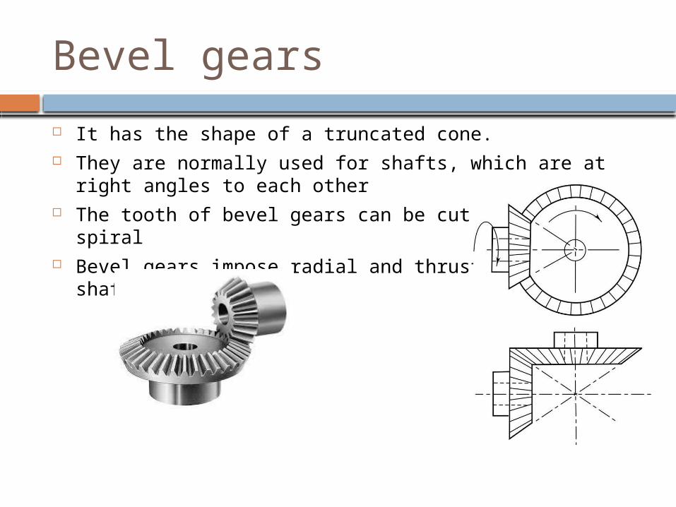
Bevel gears
It has the shape of a truncated cone. They are normally used for shafts, which are at right angles
to each other The tooth of bevel gears can be cut straight or spiral Bevel gears impose radial and thrust load on shafts
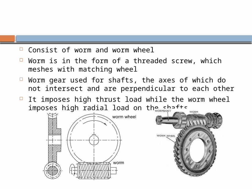
Consist of worm and worm wheel Worm is in the form of a threaded screw, which meshes
with matching wheel Worm gear used for shafts, the axes of which do not
intersect and are perpendicular to each other It imposes high thrust load while the worm wheel imposes
high radial load on the shafts
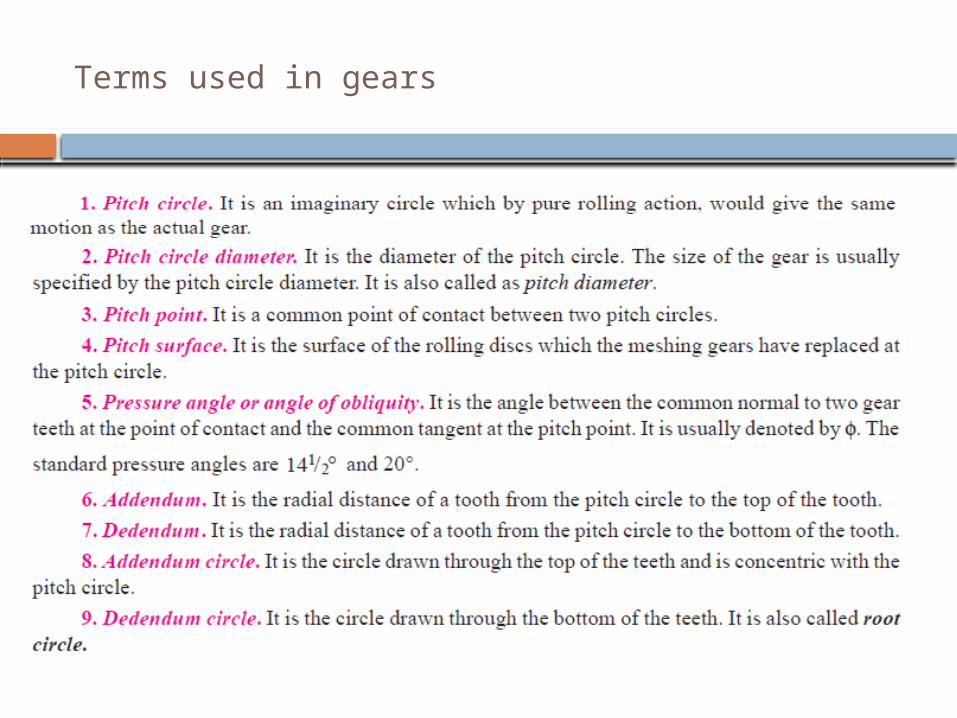
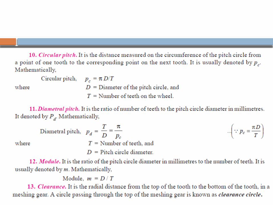
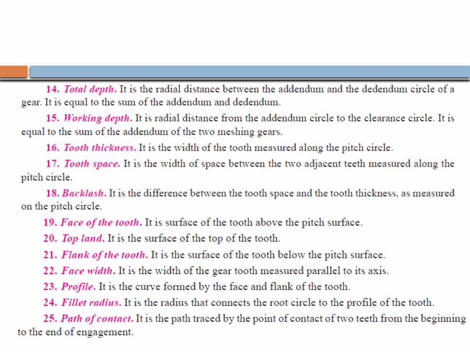
Terms used in gears
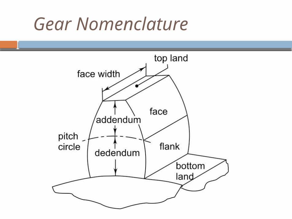
Gear Nomenclature
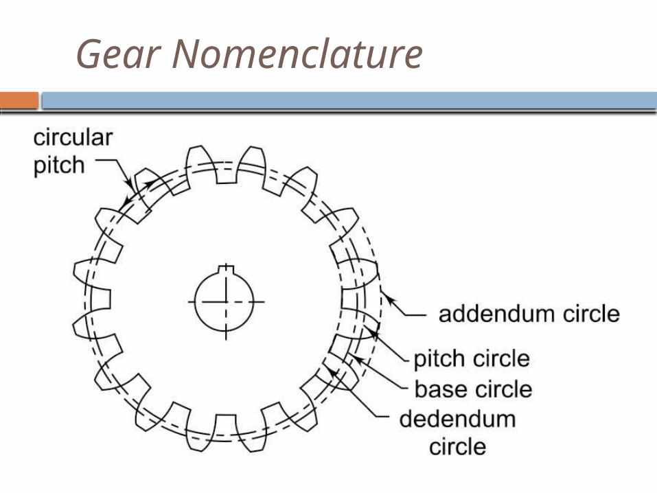
Gear Nomenclature
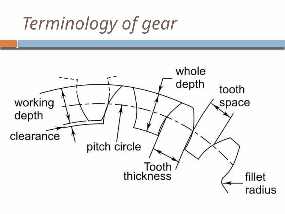
Terminology of gear
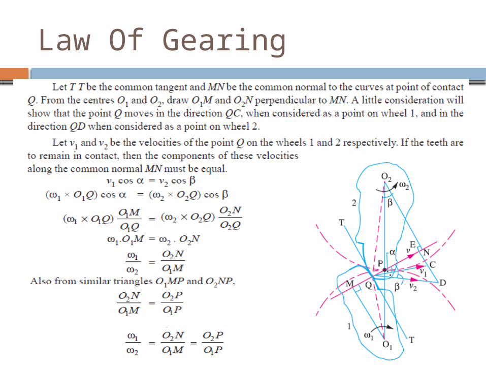
Law Of Gearing
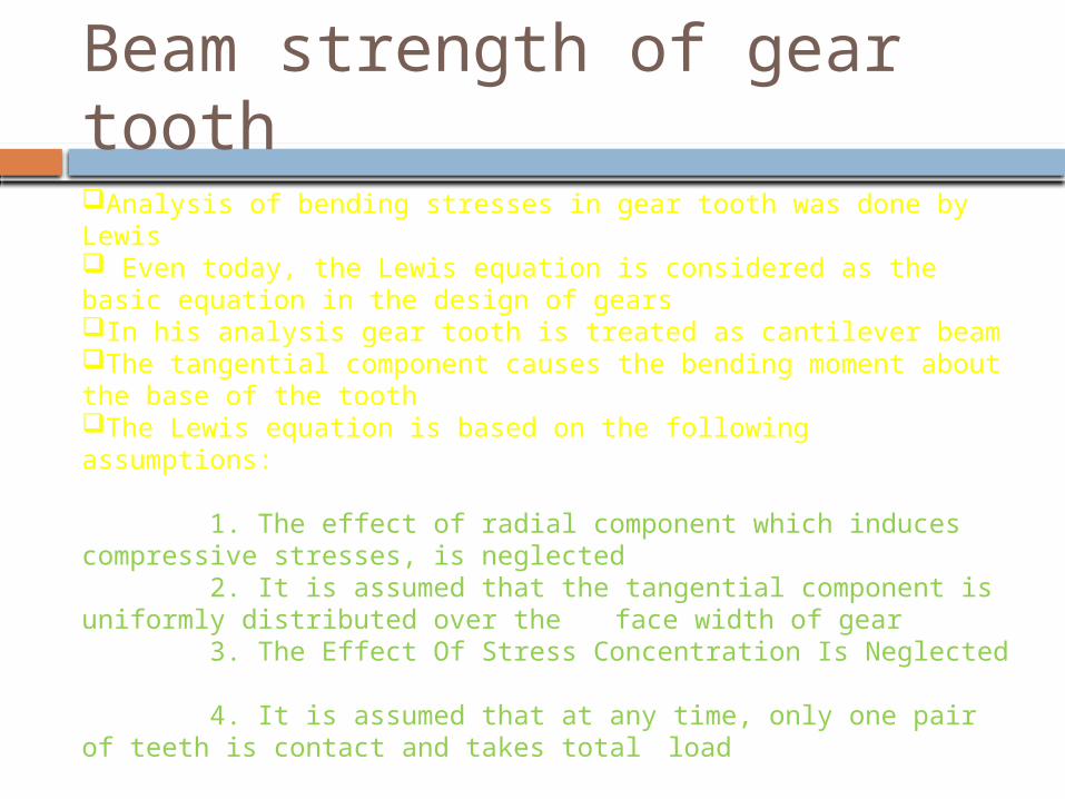
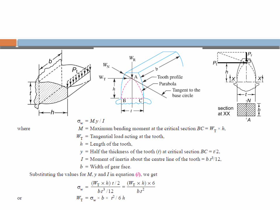
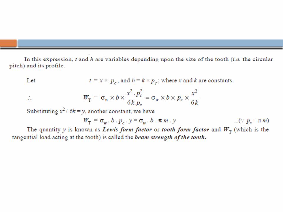
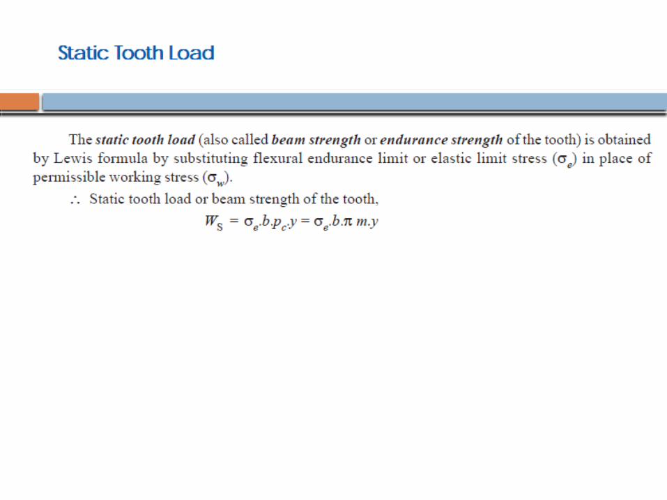
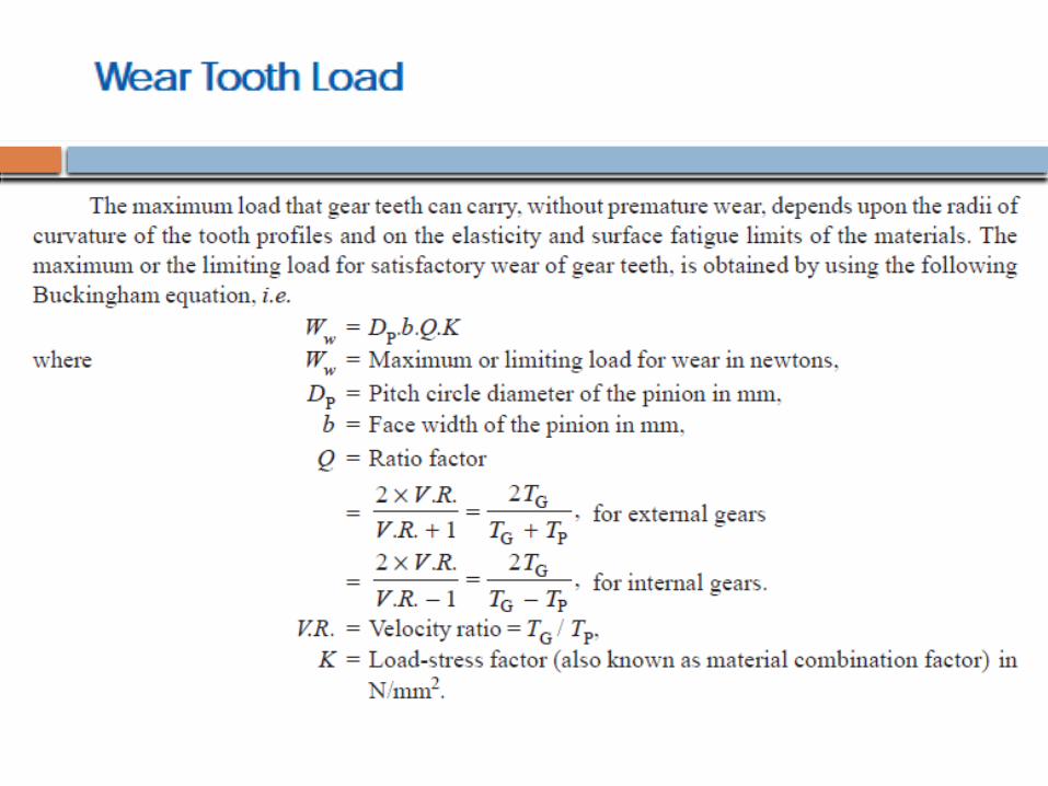
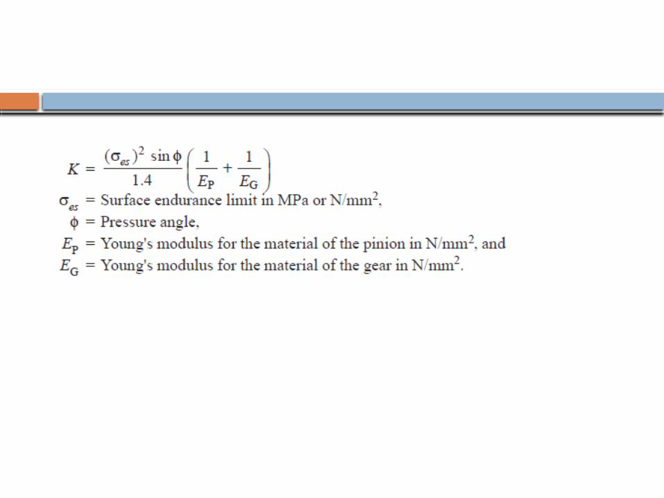
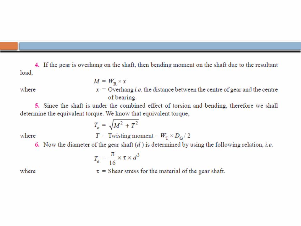
Beam strength of gear toothAnalysis of bending stresses in gear tooth was done by Lewis Even today, the Lewis equation is considered as the basic equation in the design of gearsIn his analysis gear tooth is treated as cantilever beam The tangential component causes the bending moment about the base of the toothThe Lewis equation is based on the following assumptions:
1. The effect of radial component which induces compressive stresses, is neglected 2. It is assumed that the tangential component is uniformly distributed over the face width of gear 3. The Effect Of Stress Concentration Is Neglected 4. It is assumed that at any time, only one pair of teeth is contact and takes total load
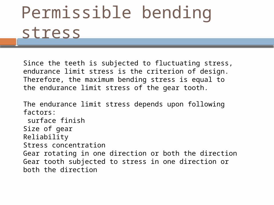
Permissible bending stress
Since the teeth is subjected to fluctuating stress, endurance limit stress is the criterion of design. Therefore, the maximum bending stress is equal to the endurance limit stress of the gear tooth.
The endurance limit stress depends upon following factors: surface finishSize of gearReliabilityStress concentrationGear rotating in one direction or both the directionGear tooth subjected to stress in one direction or both the direction
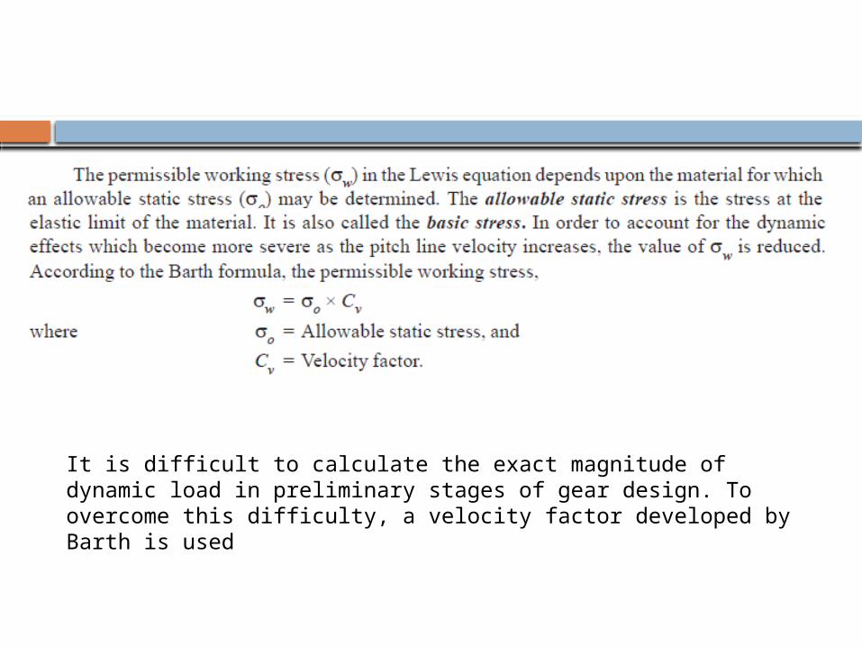
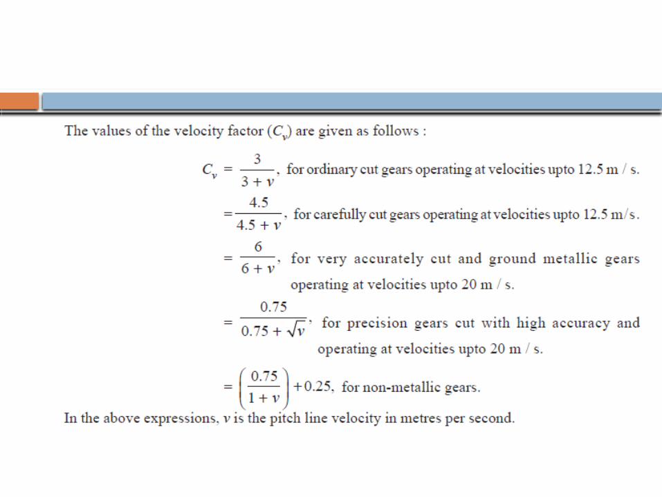
It is difficult to calculate the exact magnitude of dynamic load in preliminary stages of gear design. To overcome this difficulty, a velocity factor developed by Barth is used
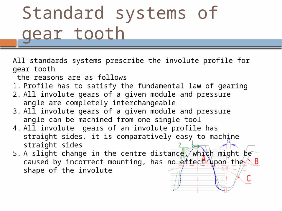
Standard systems of gear tooth
All standards systems prescribe the involute profile for gear tooth the reasons are as follows1. Profile has to satisfy the fundamental law of gearing2. All involute gears of a given module and pressure angle are
completely interchangeable3. All involute gears of a given module and pressure angle can be
machined from one single tool4. All involute gears of an involute profile has straight sides. it is
comparatively easy to machine straight sides5. A slight change in the centre distance, which might be caused by
incorrect mounting, has no effect upon the shape of the involute
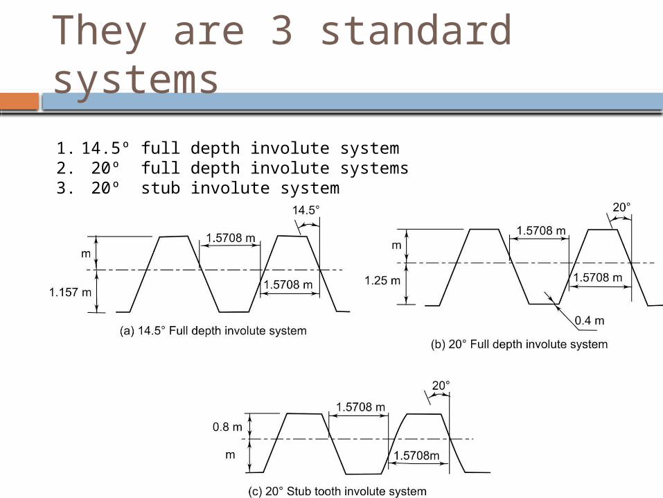
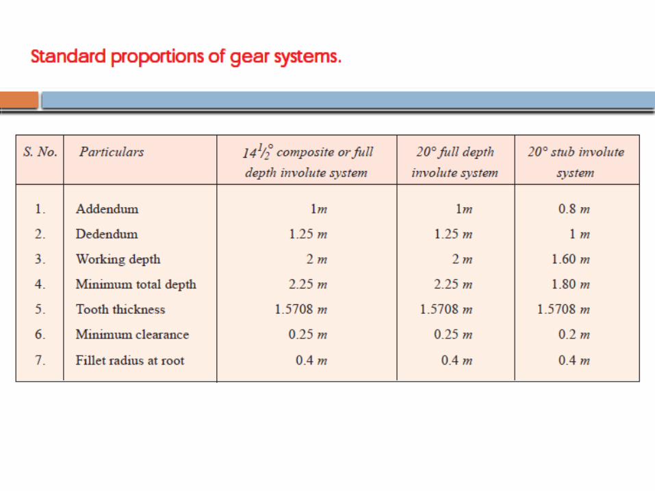
They are 3 standard systems
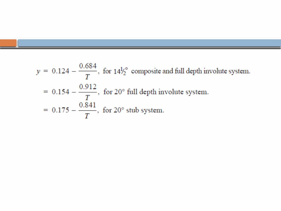
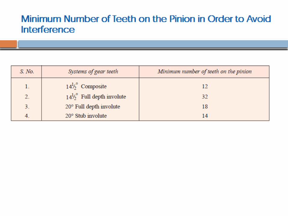
1. 14.5º full depth involute system2. 20º full depth involute systems3. 20º stub involute system
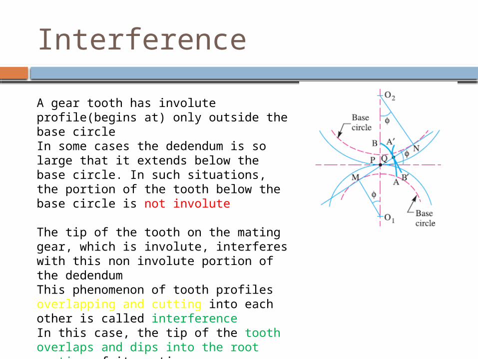
Interference
A gear tooth has involute profile(begins at) only outside the base circleIn some cases the dedendum is so large that it extends below the base circle. In such situations, the portion of the tooth below the base circle is not involute
The tip of the tooth on the mating gear, which is involute, interferes with this non involute portion of the dedendumThis phenomenon of tooth profiles overlapping and cutting into each other is called interferenceIn this case, the tip of the tooth overlaps and dips into the root section of its mating gear
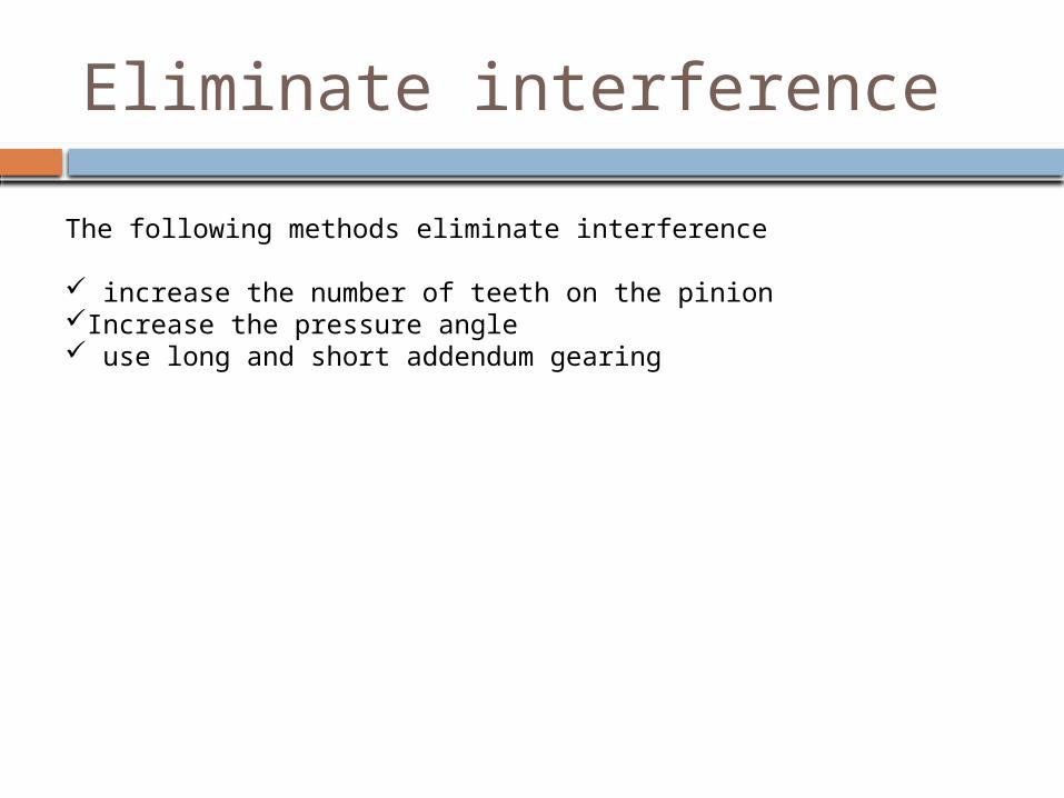
Eliminate interference
The following methods eliminate interference
increase the number of teeth on the pinionIncrease the pressure angle use long and short addendum gearing


Effective load
The effective load is given by
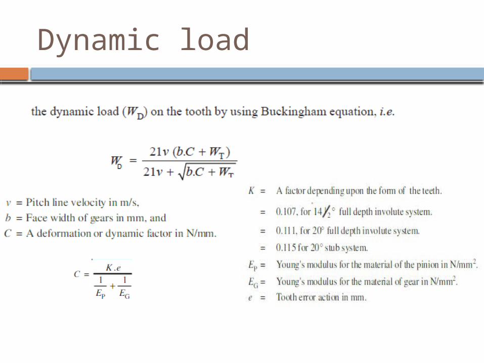
Dynamic load

Force analysis
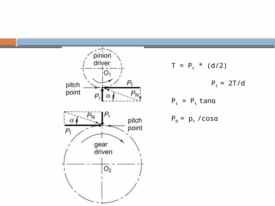
T = Pt * (d/2)
Pt = 2T/d
Pr = Pt tanα
PN = pt /cosα
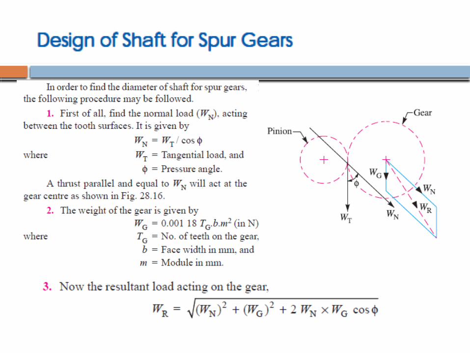
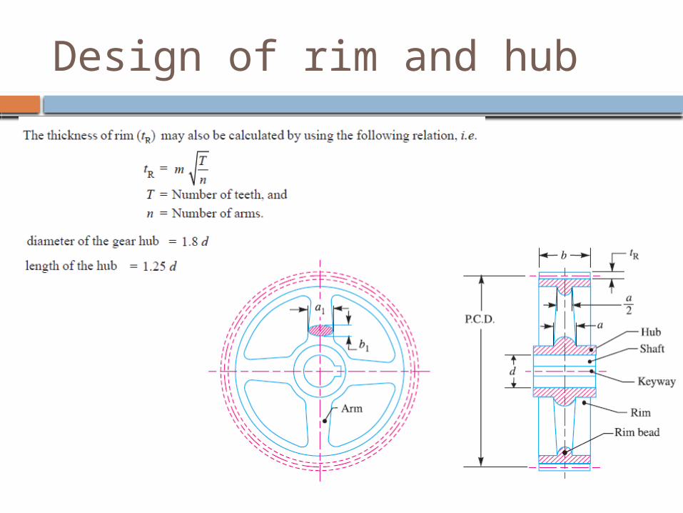
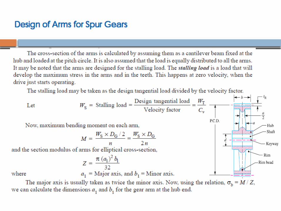
Design of rim and hub

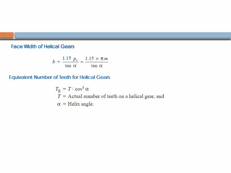
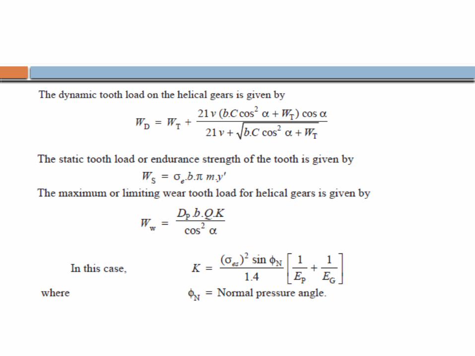
Helical gears
The teeth of these gears are cut at angle with the axis of the shaft The magnitude of helix angle of pinion and gear is same Helical gears impose radial and thrust load on shafts
There is a special type of helical gear, consisting
of two helical gears with the opposite hand of helix.
It is called herringbone gear