spyder bacnet programmable, vav/unitary controllers
TRANSCRIPT

PRODUCT DATA
63-2689-07
Spyder® BACnet®
Programmable Controllers
PRODUCT DESCRIPTIONThe PUB and PVB controllers are part of the Spyder family. These controllers are BACnet MS/TP network devices designed to control HVAC equipment. These controllers provide many options and advanced system features that allow state-of-the-art commercial building control. Each controller is programmable and configurable through software.
The Spyder BACnet controllers require the Spyder BACnet Programmable Feature to be licensed in the WEBpro workbench tool and the WEBS AX JACE Controller for programming and downloading. The Spyder BACnet Models are also available as Individually Licensed Controllers (ILC). The ILC versions are identical in design and capability in every detail except for the licensing. The Individual Licensing of the Spyder ILCs (the License is built in) allows them to be programmed and downloaded with any brand of the Niagara Workbench or JACE controller. The Spyder ILCs are identified with a suffix on the Part Number of -ILC. Example: PUB6438S-ILC follows all the same Installation Instructions information as the PUB6438S.
These controllers are for use in VAV (Variable Air Volume), Unitary and advanced HVAC control applications. Each controller has flexible, universal inputs for external sensors, digital inputs, and a combination of analog and digital Triac outputs. All the models are described in Table 1. The photo to the left is the model PVB6436AS, which includes the actuator.
Table 1. Controller configurations.
Each controller communicates via an EIA-485 BACnet MS/TP communications network, capable of baud rates between 9.6 and 115.2 kbits/s.
Controllers are field-mountable to either a panel or a DIN rail.
ControllerModel
ProgrammableType
UniversalInputs
(UI)
DigitalInputs
(DI)
AnalogOutputs
(AO)
DigitalOutputs
(DO)
VelocityPressure
Sensor(Microbridge)
Series 60FloatingActuator
PUB1012S Unitary 1 0 1 2 NO NO
PUB4024S Unitary 4 0 2 4 NO NO
PUB6438S Unitary 6 4 3 8 NO NO
PUB6438SR Unitary 6 4 3 8 Relays NO NO
PVB0000AS VAV 0 0 0 0 YES YES
PVB4022AS VAV 4 0 2 2 YES YES
PVB4024NS VAV 4 0 2 4 YES NO
PVB6436AS VAV 6 4 3 6 YES YES
PVB6438NS VAV 6 4 3 8 YES NO
SPYDER® BACNET® PROGRAMMABLE CONTROLLERS
63-2689—07 2
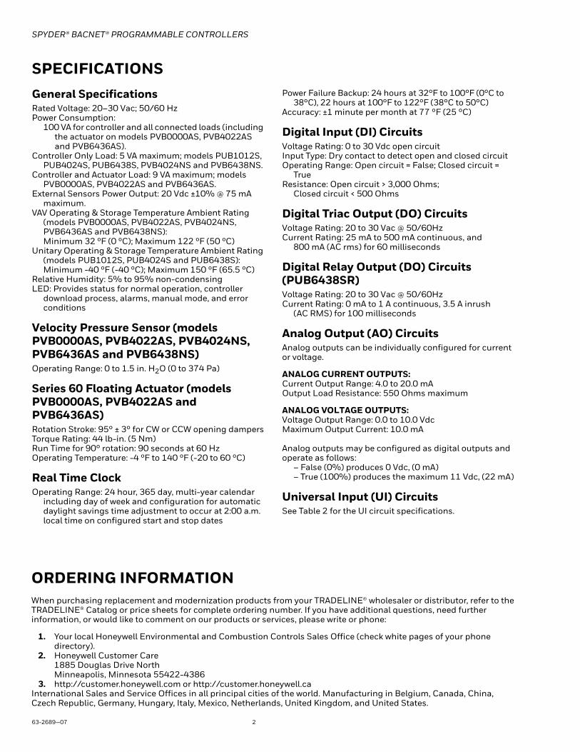
ORDERING INFORMATIONWhen purchasing replacement and modernization products from your TRADELINE® wholesaler or distributor, refer to the TRADELINE® Catalog or price sheets for complete ordering number. If you have additional questions, need further information, or would like to comment on our products or services, please write or phone:
1. Your local Honeywell Environmental and Combustion Controls Sales Office (check white pages of your phone directory).
2. Honeywell Customer Care1885 Douglas Drive NorthMinneapolis, Minnesota 55422-4386
3. http://customer.honeywell.com or http://customer.honeywell.caInternational Sales and Service Offices in all principal cities of the world. Manufacturing in Belgium, Canada, China, Czech Republic, Germany, Hungary, Italy, Mexico, Netherlands, United Kingdom, and United States.
SPECIFICATIONSGeneral SpecificationsRated Voltage: 20–30 Vac; 50/60 HzPower Consumption:
100 VA for controller and all connected loads (including the actuator on models PVB0000AS, PVB4022AS and PVB6436AS).
Controller Only Load: 5 VA maximum; models PUB1012S, PUB4024S, PUB6438S, PVB4024NS and PVB6438NS.
Controller and Actuator Load: 9 VA maximum; models PVB0000AS, PVB4022AS and PVB6436AS.
External Sensors Power Output: 20 Vdc ±10% @ 75 mA maximum.
VAV Operating & Storage Temperature Ambient Rating (models PVB0000AS, PVB4022AS, PVB4024NS, PVB6436AS and PVB6438NS):Minimum 32 ºF (0 ºC); Maximum 122 ºF (50 ºC)
Unitary Operating & Storage Temperature Ambient Rating (models PUB1012S, PUB4024S and PUB6438S):Minimum -40 ºF (-40 ºC); Maximum 150 ºF (65.5 ºC)
Relative Humidity: 5% to 95% non-condensingLED: Provides status for normal operation, controller
download process, alarms, manual mode, and error conditions
Velocity Pressure Sensor (models PVB0000AS, PVB4022AS, PVB4024NS, PVB6436AS and PVB6438NS)Operating Range: 0 to 1.5 in. H2O (0 to 374 Pa)
Series 60 Floating Actuator (models PVB0000AS, PVB4022AS and PVB6436AS)Rotation Stroke: 95° ± 3° for CW or CCW opening dampersTorque Rating: 44 lb-in. (5 Nm)Run Time for 90° rotation: 90 seconds at 60 HzOperating Temperature: -4 ºF to 140 ºF (-20 to 60 ºC)
Real Time ClockOperating Range: 24 hour, 365 day, multi-year calendar
including day of week and configuration for automatic daylight savings time adjustment to occur at 2:00 a.m. local time on configured start and stop dates
Power Failure Backup: 24 hours at 32°F to 100°F (0°C to 38°C), 22 hours at 100°F to 122°F (38°C to 50°C)
Accuracy: ±1 minute per month at 77 °F (25 °C)
Digital Input (DI) CircuitsVoltage Rating: 0 to 30 Vdc open circuitInput Type: Dry contact to detect open and closed circuitOperating Range: Open circuit = False; Closed circuit =
TrueResistance: Open circuit > 3,000 Ohms;
Closed circuit < 500 Ohms
Digital Triac Output (DO) CircuitsVoltage Rating: 20 to 30 Vac @ 50/60HzCurrent Rating: 25 mA to 500 mA continuous, and
800 mA (AC rms) for 60 milliseconds
Digital Relay Output (DO) Circuits(PUB6438SR)Voltage Rating: 20 to 30 Vac @ 50/60HzCurrent Rating: 0 mA to 1 A continuous, 3.5 A inrush
(AC RMS) for 100 milliseconds
Analog Output (AO) CircuitsAnalog outputs can be individually configured for current or voltage.
ANALOG CURRENT OUTPUTS:Current Output Range: 4.0 to 20.0 mAOutput Load Resistance: 550 Ohms maximum
ANALOG VOLTAGE OUTPUTS:Voltage Output Range: 0.0 to 10.0 VdcMaximum Output Current: 10.0 mA
Analog outputs may be configured as digital outputs and operate as follows:
– False (0%) produces 0 Vdc, (0 mA)– True (100%) produces the maximum 11 Vdc, (22 mA)
Universal Input (UI) CircuitsSee Table 2 for the UI circuit specifications.
SPYDER® BACNET® PROGRAMMABLE CONTROLLERS
3 63-2689—07
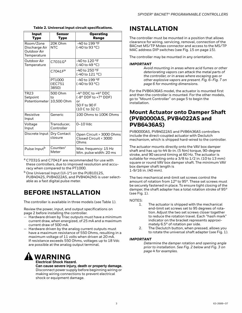
Table 2. Universal input circuit specifications.
BEFORE INSTALLATIONThe controller is available in three models (see Table 1).
Review the power, input, and output specifications on page 2 before installing the controller.— Hardware driven by Triac outputs must have a minimum
current draw, when energized, of 25 mA and a maximum current draw of 500 mA.
— Hardware driven by the analog current outputs must have a maximum resistance of 550 Ohms, resulting in a maximum voltage of 11 volts when driven at 20 mA.If resistance exceeds 550 Ohms, voltages up to 18 Vdc are possible at the analog output terminal.
WARNINGElectrical Shock Hazard.Can cause severe injury, death or property damage.Disconnect power supply before beginning wiring or making wiring connections to prevent electrical shock or equipment damage.
INSTALLATIONThe controller must be mounted in a position that allows clearance for wiring, servicing, removal, connection of the BACnet MS/TP Molex connector and access to the MS/TP MAC address DIP switches (see Fig. 15 on page 15).
The controller may be mounted in any orientation.
IMPORTANTAvoid mounting in areas where acid fumes or other deteriorating vapors can attack the metal parts of the controller, or in areas where escaping gas or other explosive vapors are present. Fig. 6–Fig. 7 on page 6 for mounting dimensions.
For the PVB6436AS model, the actuator is mounted first and then the controller is mounted. For the other models, go to “Mount Controller” on page 5 to begin the installation.
Mount Actuator onto Damper Shaft (PVB0000AS, PVB4022AS and PVB6436AS)PVB0000AS, PVB4022AS and PVB6436AS controllers include the direct-coupled actuator with Declutch mechanism, which is shipped hard-wired to the controller.
The actuator mounts directly onto the VAV box damper shaft and has up to 44 lb-in. (5 Nm) torque, 90-degree stroke, and 90 second timing at 60 Hz. The actuator is suitable for mounting onto a 3/8 to 1/2 in. (10 to 13 mm) square or round VAV box damper shaft. The minimum VAV box damper shaft length is 1-9/16 in. (40 mm).
The two mechanical end-limit set screws control the amount of rotation from 12° to 95°. These set screws must be securely fastened in place. To ensure tight closing of the damper, the shaft adapter has a total rotation stroke of 95° (see Fig. 1).
NOTES:1. The actuator is shipped with the mechanical
end-limit set screws set to 95 degrees of rota-tion. Adjust the two set screws closer together to reduce the rotation travel. Each “hash mark” indicator on the bracket represents approxi-mately 6.5° of rotation per side.
2. The Declutch button, when pressed, allows you to rotate the universal shaft adapter (see Fig. 1).
IMPORTANTDetermine the damper rotation and opening angle prior to installation. See Fig. 2 below and Fig. 3 on page 4 for examples.
InputType
SensorType
OperatingRange
Room/Zone Discharge AirOutdoor AirTemperature
20K OhmNTC
-40 to 199 °F(-40 to 93 °C)
Outdoor AirTemperature
C7031Ga
a C7031G and C7041F are recommended for use with these controllers, due to improved resolution and accu-racy when compared to the PT1000.
b One Universal Input (UI-1*) on the PUB1012S, PUB4042S, PVB4022AS, and PVB4042NS is user select-able as a fast digital pulse meter.
-40 to 120 °F (-40 to 49 °C)
C7041Fa -40 to 250 °F(-40 to 121 °C)
PT1000(IEC751 3850)
-40 to 199 °F(-40 to 93 °C)
TR23SetpointPotentiometer
500 Ohmto10,500 Ohm
-4° DDC to +4° DDC(-8° DDF to +7° DDF)or50 F to 90 F (10 C to 32 C)
Resistive Input
Generic 100 Ohms to 100K Ohms
VoltageInput
Transducer,Controller
0–10 Vdc
Discrete Input Dry Contact closure
Open Circuit > 3000 OhmsClosed Circuit < 3000 Ohms
Pulse Inputb Counter/Meter
Max. frequency: 15 HzMin. pulse width: 20 ms
SPYDER® BACNET® PROGRAMMABLE CONTROLLERS
63-2689—07 4
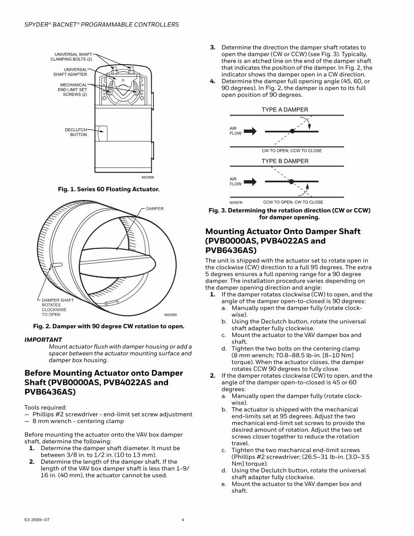
Fig. 1. Series 60 Floating Actuator.
Fig. 2. Damper with 90 degree CW rotation to open.
IMPORTANTMount actuator flush with damper housing or add a spacer between the actuator mounting surface and damper box housing.
Before Mounting Actuator onto Damper Shaft (PVB0000AS, PVB4022AS and PVB6436AS)
Tools required:— Phillips #2 screwdriver - end-limit set screw adjustment— 8 mm wrench - centering clamp
Before mounting the actuator onto the VAV box damper shaft, determine the following:
1. Determine the damper shaft diameter. It must be between 3/8 in. to 1/2 in. (10 to 13 mm).
2. Determine the length of the damper shaft. If the length of the VAV box damper shaft is less than 1-9/16 in. (40 mm), the actuator cannot be used.
3. Determine the direction the damper shaft rotates to open the damper (CW or CCW) (see Fig. 3). Typically, there is an etched line on the end of the damper shaft that indicates the position of the damper. In Fig. 2, the indicator shows the damper open in a CW direction.
4. Determine the damper full opening angle (45, 60, or 90 degrees). In Fig. 2, the damper is open to its full open position of 90 degrees.
Fig. 3. Determining the rotation direction (CW or CCW) for damper opening.
Mounting Actuator Onto Damper Shaft (PVB0000AS, PVB4022AS and PVB6436AS)The unit is shipped with the actuator set to rotate open in the clockwise (CW) direction to a full 95 degrees. The extra 5 degrees ensures a full opening range for a 90 degree damper. The installation procedure varies depending on the damper opening direction and angle:
1. If the damper rotates clockwise (CW) to open, and the angle of the damper open-to-closed is 90 degrees:a. Manually open the damper fully (rotate clock-
wise). b. Using the Declutch button, rotate the universal
shaft adapter fully clockwise. c. Mount the actuator to the VAV damper box and
shaft. d. Tighten the two bolts on the centering clamp
(8 mm wrench; 70.8–88.5 lb-in. [8–10 Nm] torque). When the actuator closes, the damper rotates CCW 90 degrees to fully close.
2. If the damper rotates clockwise (CW) to open, and the angle of the damper open-to-closed is 45 or 60 degrees:a. Manually open the damper fully (rotate clock-
wise).b. The actuator is shipped with the mechanical
end-limits set at 95 degrees. Adjust the two mechanical end-limit set screws to provide the desired amount of rotation. Adjust the two set screws closer together to reduce the rotation travel.
c. Tighten the two mechanical end-limit screws (Phillips #2 screwdriver; (26.5–31 lb-in. [3.0–3.5 Nm] torque).
d. Using the Declutch button, rotate the universal shaft adapter fully clockwise.
e. Mount the actuator to the VAV damper box and shaft.
UNIVERSAL SHAFTCLAMPING BOLTS (2)
M23568
UNIVERSALSHAFT ADAPTER
MECHANICALEND LIMIT SET
SCREWS (2)
DECLUTCHBUTTON
M23569
DAMPER SHAFT ROTATES CLOCKWISE TO OPEN
DAMPER
AIR
FLOW
AIR
FLOW
CW TO OPEN, CCW TO CLOSE
CCW TO OPEN, CW TO CLOSEM2067B
TYPE A DAMPER
TYPE B DAMPER
SPYDER® BACNET® PROGRAMMABLE CONTROLLERS
5 63-2689—07
f. Tighten the two bolts on the centering clamp (8 mm wrench; 70.8–88.5 lb-in. [8–10 Nm] torque).
g. When the actuator closes, the damper rotates CCW either 45 or 60 degrees to fully close.
3. If the damper rotates counterclockwise (CCW) to open, and the angle of the damper open-to-closed is 90 degrees:a. Manually open the damper fully (rotate counter-
clockwise).b. Using the Declutch button, rotate the universal
shaft adapter fully counterclockwise. c. Mount the actuator to the damper box and shaft. d. Tighten the two bolts on the centering clamp (8
mm wrench; 70.8–88.5 lb-in. [8–10 Nm] torque). When the actuator closes, the damper rotates CW 90 degrees to fully close.
4. If the damper rotates counterclockwise to open, and the angle of the damper open-to-closed is 45 or 60 degrees:a. Manually open the damper fully (rotate counter-
clockwise).b. The actuator is shipped with the mechanical
end-limits set at 95 degrees. Adjust the two mechanical end-limit set screws to provide the desired amount of rotation. Adjust the two set screws closer together to reduce the rotation travel.
c. Tighten the two mechanical end-limit screws (Phillips #2 screwdriver; (26.5–31 lb-in. [3.0–3.5 Nm] torque).
d. Using the Declutch button, rotate the universal shaft adapter fully counter-clockwise.
e. Mount the actuator to the VAV damper box and shaft.
f. Tighten the two bolts on the centering clamp (8 mm wrench; 70.8–88.5 lb-in. [8–10 Nm] torque).
g. When the actuator closes, the damper rotates CW either 45 or 60 degrees to fully close.
IMPORTANTSpecial precautions must be taken for dampers that open in a CCW direction. The actuator is shipped with its rotation direction set to CW to Open, which applies to the damper direction in steps 1 and 2 above. If the damper shaft rotates in the CCW direc-tion to open, the controller software must be pro-grammed to change the rotation to “Reverse to Open,” which applies to the damper direction in steps 3 and 4 above.
IMPORTANTIt is advisable to leave the dampers in an open position after installation to avoid the possibility of over-pressurizing the duct work on fan startup. Use the Declutch button (see Fig. 1 on page 4) to open the box damper on controllers that are powered down, to prevent over-pressurization in the duct work on fan startup. To Declutch, press and hold
the button to disengage the motor. Turn the damper shaft until the damper is open and release the button. When power is restored to the controller, the controller synchronizes the damper actuator, so that the damper is in the correct position upon startup.
Mount ControllerNOTE: The controller may be wired before mounting to a
panel or DIN rail.
Terminal blocks are used to make all wiring connections to the controller. Attach all wiring to the appropriate terminal blocks (see “Wiring” on page 9).
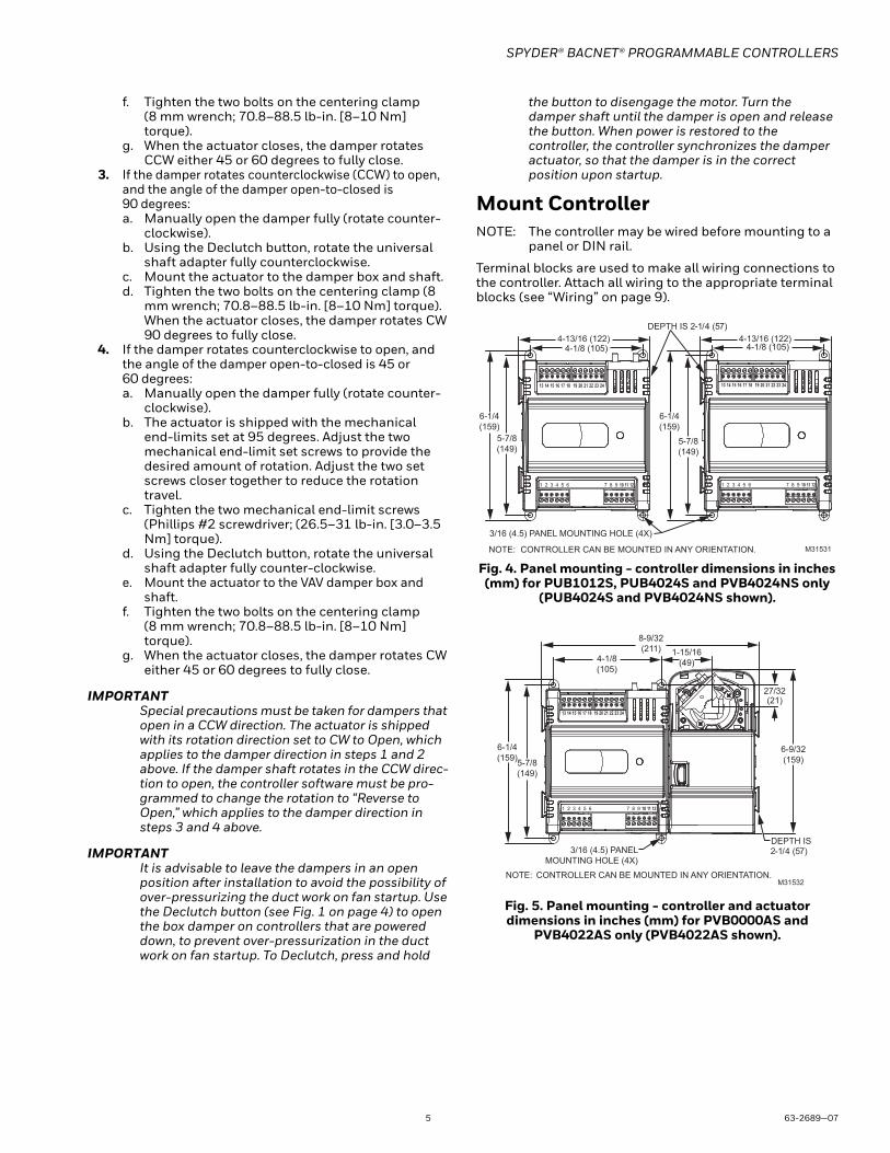
Fig. 4. Panel mounting - controller dimensions in inches (mm) for PUB1012S, PUB4024S and PVB4024NS only
(PUB4024S and PVB4024NS shown).
Fig. 5. Panel mounting - controller and actuator dimensions in inches (mm) for PVB0000AS and
PVB4022AS only (PVB4022AS shown).
M31531NOTE: CONTROLLER CAN BE MOUNTED IN ANY ORIENTATION.
3/16 (4.5) PANEL MOUNTING HOLE (4X)
DEPTH IS 2-1/4 (57)
4-13/16 (122)4-1/8 (105)
6-1/4
(159)
5-7/8
(149)
4-13/16 (122)4-1/8 (105)
6-1/4
(159)
5-7/8
(149)
1 2 3 4 5 6 7 8 9 10 11 12 1 2 3 4 5 6 7 8 9 10 11 12
13 14 15 16 17 18 19 20 21 22 23 24 13 14 15 16 17 18 19 20 21 22 23 24
NOTE: CONTROLLER CAN BE MOUNTED IN ANY ORIENTATION.M31532
8-9/32
(211) 1-15/16
(49)
6-9/32
(159)
3/16 (4.5) PANEL
MOUNTING HOLE (4X)
27/32(21)
4-1/8
(105)
6-1/4
(159)5-7/8
(149)
DEPTH IS 2-1/4 (57)
1 2 3 4 5 6 7 8 9 10 11 12
13 14 15 16 17 18 19 20 21 22 23 24
SPYDER® BACNET® PROGRAMMABLE CONTROLLERS
63-2689—07 6
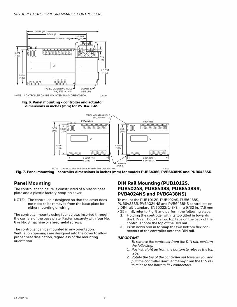
Fig. 6. Panel mounting - controller and actuator dimensions in inches (mm) for PVB6436AS.
Fig. 7. Panel mounting - controller dimensions in inches (mm) for models PUB6438S, PVB6438NS and PUB6438SR.
Panel MountingThe controller enclosure is constructed of a plastic base plate and a plastic factory-snap-on cover.
NOTE: The controller is designed so that the cover does not need to be removed from the base plate for either mounting or wiring.
The controller mounts using four screws inserted through the corners of the base plate. Fasten securely with four No. 6 or No. 8 machine or sheet metal screws.
The controller can be mounted in any orientation. Ventilation openings are designed into the cover to allow proper heat dissipation, regardless of the mounting orientation.
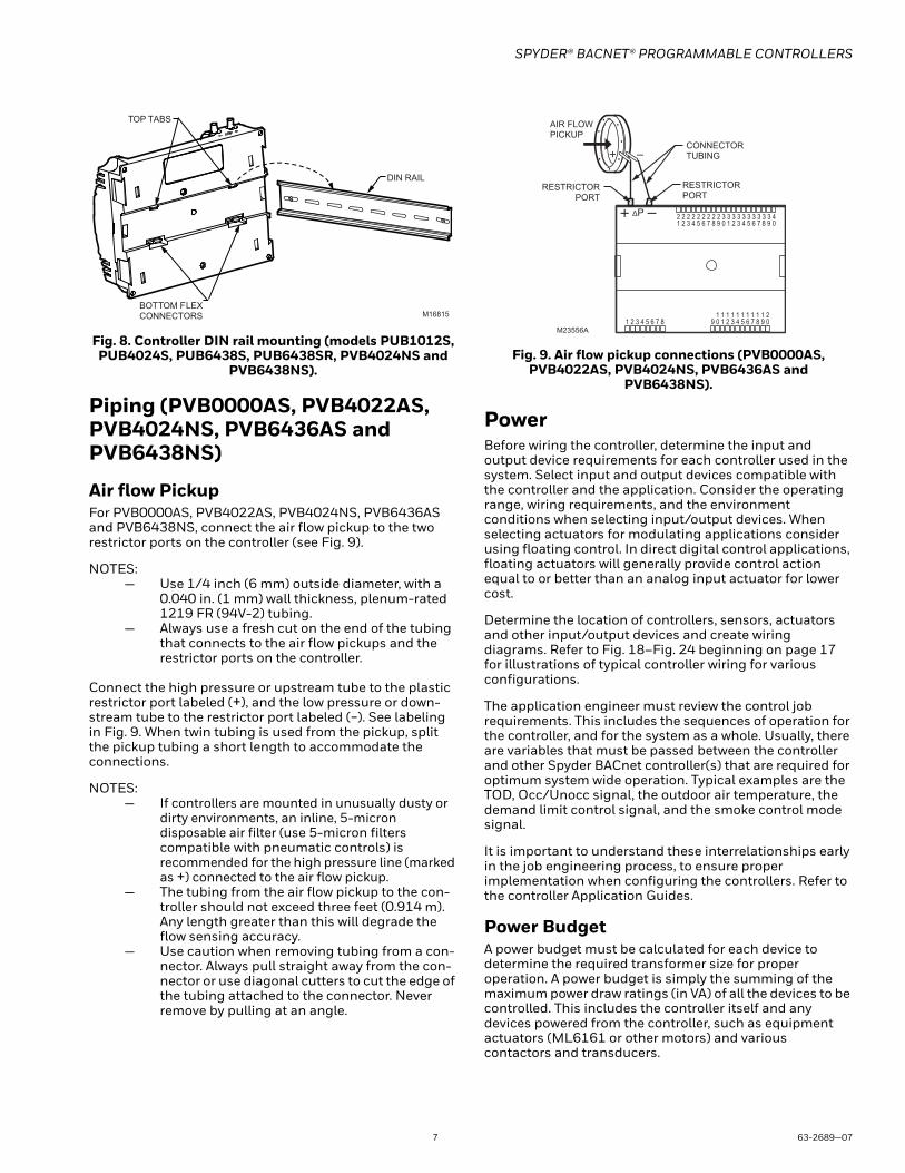
DIN Rail Mounting (PUB1012S, PUB4024S, PUB6438S, PUB6438SR, PVB4024NS and PVB6438NS)To mount the PUB1012S, PUB4024S, PUB6438S, PUB6438SR, PVB4024NS and PVB6438NS controllers on a DIN rail [standard EN50022; 1-3/8 in. x 9/32 in. (7.5 mm x 35 mm)], refer to Fig. 8 and perform the following steps:
1. Holding the controller with its top tilted in towards the DIN rail, hook the two top tabs on the back of the controller onto the top of the DIN rail.
2. Push down and in to snap the two bottom flex con-nectors of the controller onto the DIN rail.
IMPORTANTTo remove the controller from the DIN rail, perform the following:
1. Push straight up from the bottom to release the top tabs.
2. Rotate the top of the controller out towards you and pull the controller down and away from the DIN rail to release the bottom flex connectors.
1 2 3 4 5 6 7 8 109 2 3 4 5 6 711 1 1 1 1 1 1
1 2 3 4 5 6 7 8 0922 2 2 2 2 2 2 2 33
1 2 3 4 5 6 7 8 0933 33 33 33 4
5-3/4
(146)
10-5/16 (262)
NOTE: CONTROLLER CAN BE MOUNTED IN ANY ORIENTATION.
PANEL MOUNTING HOLE(4X) 3/16 IN. (4.5)
M29329
5-3/64
(128)
8-5/16 (211)
6-29/64 (164)1-55/64
(47)
6-17/64
(159)
7/16
(11)
DEPTH IS 2-1/4 (57)
1 2 3 4 5 6 7 8 1 0 9 2 3 4 5 6 7 8 0 9 1 1 1 1 1 1 1 1 1 2 1
1 2 3 4 5 6 7 8 0 9 2 2 2 2 2 2 2 2 2 3 3
1 2 3 4 5 6 7 8 0 9 3 3 3 3 3 3 3 3 4
5-3/4 (146)
6-27/32 (174)
NOTE: CONTROLLER CAN BE MOUNTED IN ANY ORIENTATION.
PANEL MOUNTING HOLE (4X) 29/64 IN. (12)
M29330
5-3/64 (128)
6-29/64 (164)
5-29/64
(139)
1 2 3 4 5 6 7 8 1 0 9 2 3 4 5 6 7 8 0 9 1 1 1 1 1 1 1 1 1 2 1
1 2 3 4 5 6 7 8 0 9 2 2 2 2 2 2 2 2 2 3 3
1 2 3 4 5 6 7 8 0 9 3 3 3 3 3 3 3 3 4
6-27/32 (174)
5-3/64 (128)
6-29/64 (164)
5-29/64
(139)
PVB6438NS PUB6438S
DEPTH IS 2-1/4 (57)
SPYDER® BACNET® PROGRAMMABLE CONTROLLERS
7 63-2689—07
Fig. 8. Controller DIN rail mounting (models PUB1012S, PUB4024S, PUB6438S, PUB6438SR, PVB4024NS and
PVB6438NS).
Piping (PVB0000AS, PVB4022AS, PVB4024NS, PVB6436AS and PVB6438NS)
Air flow PickupFor PVB0000AS, PVB4022AS, PVB4024NS, PVB6436AS and PVB6438NS, connect the air flow pickup to the two restrictor ports on the controller (see Fig. 9).
NOTES:— Use 1/4 inch (6 mm) outside diameter, with a
0.040 in. (1 mm) wall thickness, plenum-rated 1219 FR (94V-2) tubing.
— Always use a fresh cut on the end of the tubing that connects to the air flow pickups and the restrictor ports on the controller.
Connect the high pressure or upstream tube to the plastic restrictor port labeled (+), and the low pressure or down-stream tube to the restrictor port labeled (-). See labeling in Fig. 9. When twin tubing is used from the pickup, split the pickup tubing a short length to accommodate the connections.
NOTES:— If controllers are mounted in unusually dusty or
dirty environments, an inline, 5-micron disposable air filter (use 5-micron filters compatible with pneumatic controls) is recommended for the high pressure line (marked as +) connected to the air flow pickup.
— The tubing from the air flow pickup to the con-troller should not exceed three feet (0.914 m). Any length greater than this will degrade the flow sensing accuracy.
— Use caution when removing tubing from a con-nector. Always pull straight away from the con-nector or use diagonal cutters to cut the edge of the tubing attached to the connector. Never remove by pulling at an angle.
Fig. 9. Air flow pickup connections (PVB0000AS, PVB4022AS, PVB4024NS, PVB6436AS and
PVB6438NS).
PowerBefore wiring the controller, determine the input and output device requirements for each controller used in the system. Select input and output devices compatible with the controller and the application. Consider the operating range, wiring requirements, and the environment conditions when selecting input/output devices. When selecting actuators for modulating applications consider using floating control. In direct digital control applications, floating actuators will generally provide control action equal to or better than an analog input actuator for lower cost.
Determine the location of controllers, sensors, actuators and other input/output devices and create wiring diagrams. Refer to Fig. 18–Fig. 24 beginning on page 17 for illustrations of typical controller wiring for various configurations.
The application engineer must review the control job requirements. This includes the sequences of operation for the controller, and for the system as a whole. Usually, there are variables that must be passed between the controller and other Spyder BACnet controller(s) that are required for optimum system wide operation. Typical examples are the TOD, Occ/Unocc signal, the outdoor air temperature, the demand limit control signal, and the smoke control mode signal.
It is important to understand these interrelationships early in the job engineering process, to ensure proper implementation when configuring the controllers. Refer to the controller Application Guides.
Power BudgetA power budget must be calculated for each device to determine the required transformer size for proper operation. A power budget is simply the summing of the maximum power draw ratings (in VA) of all the devices to be controlled. This includes the controller itself and any devices powered from the controller, such as equipment actuators (ML6161 or other motors) and various contactors and transducers.
DIN RAIL
TOP TABS
BOTTOM FLEXCONNECTORS M16815
M23556A
AIR FLOW PICKUP
ΔP
1 2 3 4 5 6 7 8 1 0 9 2 3 4 5 6 7 8 0 9 1 1 1 1 1 1 1 1 1 2 1
1 2 3 4 5 6 7 8 0 9 2 2 2 2 2 2 2 2 2 3 3
1 2 3 4 5 6 7 8 0 9 3 3 3 3 3 3 3 3 4
RESTRICTOR PORT
RESTRICTOR PORT
CONNECTOR TUBING
SPYDER® BACNET® PROGRAMMABLE CONTROLLERS
63-2689—07 8
IMPORTANT• When multiple controllers operate from a single
transformer, connect the same side of the transformer secondary to the same power input terminal in each device. The earth ground terminal (terminal 3) must be connected to a verified earth ground for each controller in the group (see Fig. 12 on page 10).
• Half-wave devices and full-wave devices must not use the same AC transformer. If a Spyder controller will share its power supply with another device, make sure the other device utilizes a half-wave rectifier and that the polarity of the wiring is maintained.
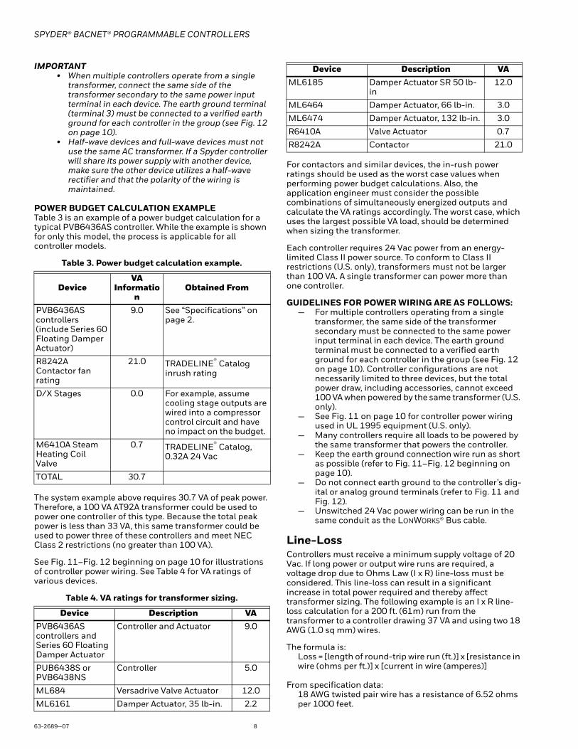
POWER BUDGET CALCULATION EXAMPLETable 3 is an example of a power budget calculation for a typical PVB6436AS controller. While the example is shown for only this model, the process is applicable for all controller models.
Table 3. Power budget calculation example.
The system example above requires 30.7 VA of peak power. Therefore, a 100 VA AT92A transformer could be used to power one controller of this type. Because the total peak power is less than 33 VA, this same transformer could be used to power three of these controllers and meet NEC Class 2 restrictions (no greater than 100 VA).
See Fig. 11–Fig. 12 beginning on page 10 for illustrations of controller power wiring. See Table 4 for VA ratings of various devices.
Table 4. VA ratings for transformer sizing.
For contactors and similar devices, the in-rush power ratings should be used as the worst case values when performing power budget calculations. Also, the application engineer must consider the possible combinations of simultaneously energized outputs and calculate the VA ratings accordingly. The worst case, which uses the largest possible VA load, should be determined when sizing the transformer.
Each controller requires 24 Vac power from an energy-limited Class II power source. To conform to Class II restrictions (U.S. only), transformers must not be larger than 100 VA. A single transformer can power more than one controller.
GUIDELINES FOR POWER WIRING ARE AS FOLLOWS:— For multiple controllers operating from a single
transformer, the same side of the transformer secondary must be connected to the same power input terminal in each device. The earth ground terminal must be connected to a verified earth ground for each controller in the group (see Fig. 12 on page 10). Controller configurations are not necessarily limited to three devices, but the total power draw, including accessories, cannot exceed 100 VA when powered by the same transformer (U.S. only).
— See Fig. 11 on page 10 for controller power wiring used in UL 1995 equipment (U.S. only).
— Many controllers require all loads to be powered by the same transformer that powers the controller.
— Keep the earth ground connection wire run as short as possible (refer to Fig. 11–Fig. 12 beginning on page 10).
— Do not connect earth ground to the controller’s dig-ital or analog ground terminals (refer to Fig. 11 and Fig. 12).
— Unswitched 24 Vac power wiring can be run in the same conduit as the LONWORKS® Bus cable.
Line-LossControllers must receive a minimum supply voltage of 20 Vac. If long power or output wire runs are required, a voltage drop due to Ohms Law (I x R) line-loss must be considered. This line-loss can result in a significant increase in total power required and thereby affect transformer sizing. The following example is an I x R line-loss calculation for a 200 ft. (61m) run from the transformer to a controller drawing 37 VA and using two 18 AWG (1.0 sq mm) wires.
The formula is:Loss = [length of round-trip wire run (ft.)] x [resistance in wire (ohms per ft.)] x [current in wire (amperes)]
From specification data:18 AWG twisted pair wire has a resistance of 6.52 ohms per 1000 feet.
DeviceVA
Information
Obtained From
PVB6436AS controllers (include Series 60 Floating Damper Actuator)
9.0 See “Specifications” on page 2.
R8242A Contactor fan rating
21.0 TRADELINE® Catalog inrush rating
D/X Stages 0.0 For example, assume cooling stage outputs are wired into a compressor control circuit and have no impact on the budget.
M6410A Steam Heating Coil Valve
0.7 TRADELINE® Catalog, 0.32A 24 Vac
TOTAL 30.7
Device Description VAPVB6436AS controllers and Series 60 Floating Damper Actuator
Controller and Actuator 9.0
PUB6438S or PVB6438NS
Controller 5.0
ML684 Versadrive Valve Actuator 12.0
ML6161 Damper Actuator, 35 lb-in. 2.2
ML6185 Damper Actuator SR 50 lb-in
12.0
ML6464 Damper Actuator, 66 lb-in. 3.0
ML6474 Damper Actuator, 132 lb-in. 3.0
R6410A Valve Actuator 0.7
R8242A Contactor 21.0
Device Description VA
SPYDER® BACNET® PROGRAMMABLE CONTROLLERS
9 63-2689—07
Loss = [(400 ft.) x (6.52/1000 ohms per ft.)] x [(37 VA)/(24V)] = 4.02 volts
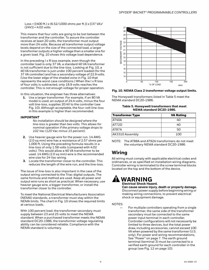
This means that four volts are going to be lost between the transformer and the controller. To assure the controller receives at least 20 volts, the transformer must output more than 24 volts. Because all transformer output voltage levels depend on the size of the connected load, a larger transformer outputs a higher voltage than a smaller one for a given load. Fig. 10 shows this voltage load dependence.
In the preceding I x R loss example, even though the controller load is only 37 VA, a standard 40 VA transformer is not sufficient due to the line-loss. Looking at Fig. 10, a 40 VA transformer is just under 100 percent loaded (for the 37 VA controller) and has a secondary voltage of 22.9 volts. (Use the lower edge of the shaded zone in Fig. 10 that represents the worst case conditions.) When the I x R loss of four volts is subtracted, only 18.9 volts reaches the controller. This is not enough voltage for proper operation.
In this situation, the engineer has three alternatives:1. Use a larger transformer. For example, if an 80 VA
model is used, an output of 24.4 volts, minus the four volt line-loss, supplies 20.4V to the controller (see Fig. 10). Although acceptable, the four-volt line-loss in this example is higher than recommended.
IMPORTANTNo installation should be designed where the line-loss is greater than two volts. This allows for nominal operation if the primary voltage drops to 102 Vac (120 Vac minus 15 percent).
2. Use heavier gauge wire for the power run. 14 AWG (2.0 sq mm) wire has a resistance of 2.57 ohms per 1,000 ft. Using the preceding formula results in a line-loss of only 1.58 volts (compared with 4.02 volts). This would allow a 40 VA transformer to be used. 14 AWG (2.0 sq mm) wire is the recommended wire size for 24 Vac wiring.
3. Locate the transformer closer to the controller. This reduces the length of the wire run, and the line-loss.
The issue of line-loss is also important in the case of the output wiring connected to the Triac digital outputs. The same formula and method are used. Keep all power and output wire runs as short as practical. When necessary, use heavier gauge wire, a bigger transformer, or install the transformer closer to the controller.
To meet the National Electrical Manufacturers Association (NEMA) standards, a transformer must stay within the NEMA limits. The chart in Fig. 10 shows the required limits at various loads.
With 100 percent load, the transformer secondary must supply between 23 and 25 volts to meet the NEMA standard. When a purchased transformer meets the NEMA standard DC20-1986, the transformer voltage regulating ability can be considered reliable. Compliance with the NEMA standard is voluntary.
Fig. 10. NEMA Class 2 transformer voltage output limits.
The Honeywell transformers listed in Table 5 meet the NEMA standard DC20-1986.
Table 5. Honeywell transformers that meet NEMA standard DC20-1986.
NOTE: The AT88A and AT92A transformers do not meet the voluntary NEMA standard DC20-1986.
WiringAll wiring must comply with applicable electrical codes and ordinances, or as specified on installation wiring diagrams. Controller wiring is terminated to the screw terminal blocks located on the top and the bottom of the device.
WARNINGElectrical Shock Hazard.Can cause severe injury, death or property damage.Disconnect power supply before beginning wiring or making wiring connections, to prevent electrical shock or equipment damage.
NOTES:— For multiple controllers operating from a single
transformer, the same side of the transformer secondary must be connected to the same power input terminal in each controller. Controller configurations will not necessarily be limited to three devices, but the total power draw, including accessories, cannot exceed 100 VA when powered by the same transformer (U.S. only). For power and wiring recommendations, See “Power” on page 7. The earth ground terminal (terminal 3) must be connected to a verified earth ground for each controller in the group (see Fig. 12 on page 10).
Transformer Type VA RatingAT40A 40
AT72D 40
AT87A 50
AK3310 Assembly 100
27
26
25
24
23
22
21
20
19
18
17
16
15
14
0 50 100 150
% OF LOAD
SE
CO
ND
AR
Y V
OLTA
GE
200
M993
SPYDER® BACNET® PROGRAMMABLE CONTROLLERS
63-2689—07 10
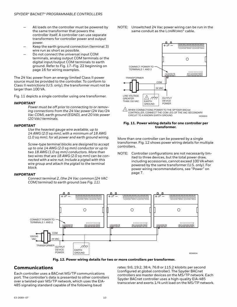
— All loads on the controller must be powered by the same transformer that powers the controller itself. A controller can use separate transformers for controller power and output power.
— Keep the earth ground connection (terminal 3) wire run as short as possible.
— Do not connect the universal input COM terminals, analog output COM terminals or the digital input/output COM terminals to earth ground. Refer to Fig. 17–Fig. 22 beginning on page 16 for wiring examples.
The 24 Vac power from an energy limited Class II power source must be provided to the controller. To conform to Class II restrictions (U.S. only), the transformer must not be larger than 100 VA.
Fig. 11 depicts a single controller using one transformer.
IMPORTANTPower must be off prior to connecting to or remov-ing connections from the 24 Vac power (24 Vac/24 Vac COM), earth ground (EGND), and 20 Vdc power (20 Vdc) terminals.
IMPORTANTUse the heaviest gauge wire available, up to 14 AWG (2.0 sq mm), with a minimum of 18 AWG (1.0 sq mm), for all power and earth ground wiring.
Screw-type terminal blocks are designed to accept up to one 14 AWG (2.0 sq mm) conductor or up to two 18 AWG (1.0 sq mm) conductors. More than two wires that are 18 AWG (2.0 sq mm) can be con-nected with a wire nut. Include a pigtail with this wire group and attach the pigtail to the terminal block.
IMPORTANTConnect terminal 2, (the 24 Vac common [24 VAC COM] terminal) to earth ground (see Fig. 11).
NOTE: Unswitched 24 Vac power wiring can be run in the same conduit as the LONWORKS® cable.
Fig. 11. Power wiring details for one controller per transformer.
More than one controller can be powered by a single transformer. Fig. 12 shows power wiring details for multiple controllers.
NOTE: Controller configurations are not necessarily lim-ited to three devices, but the total power draw, including accessories, cannot exceed 100 VA when powered by the same transformer (U.S. only). For power wiring recommendations, see “Power” on page 7.
Fig. 12. Power wiring details for two or more controllers per transformer.
CommunicationsEach controller uses a BACnet MS/TP communications port. The controller’s data is presented to other controllers over a twisted-pair MS/TP network, which uses the EIA-485 signaling standard capable of the following baud
rates: 9.6, 19.2, 38.4, 76.8 or 115.2 kilobits per second (configured at global controller). The Spyder BACnet controllers are master devices on the MS/TP network. Each Spyder BACnet controller uses a high-quality EIA-485 transceiver and exerts 1/4 unit load on the MS/TP network.
M29684A
TRANSFORMER
OUTPUTDEVICEPOWER
ΔP
12345678 109 2345678 0911 1111111 21
12345678 0922 2222222 33
12345678 0933 33 33 33 4
EARTHGROUND
1LINE VOLTAGEGREATERTHAN 150 VAC
WHEN CONNECTIONG POWER TO THE SPYDER BACnet CONTROLLER, CONNECT THE COM LEG OF THE VAC SECONDARY CIRCUIT TO A KNOWN EARTH GROUND.
1
COM
24 VAC
CONNECT POWER TO TERMINALS 1 AND 2
M29685A
120/240VAC
TRANSFORMEROUTPUTDEVICEPOWER
ΔP
12345678 109 2345678 0911 1111111 21
12345678 0922 2222222 33
12345678 0933 33 33 33 4
COM
24 VAC
ΔP
12345678 109 2345678 0911 1111111 21
12345678 0922 2222222 33
12345678 0933 33 33 33 4 ΔP
12345678 109 2345678 0911 1111111 21
12345678 0922 2222222 33
12345678 0933 33 33 33 4
CONNECT POWER TO TERMINALS 1 AND 2
EARTHGROUND

SPYDER® BACNET® PROGRAMMABLE CONTROLLERS
11 63-2689—07
Cabling should be selected that meets or exceeds the BACnet Standard which specifies the following: An MS/TP EIA-485 network shall use shielded, twisted-pair cable with characteristic impedance between 100 and 130 ohms. Distributed capacitance between conductors shall be less than 100 pF per meter (30 pF per foot). Distributed capacitance between conductors and shield shall be less that 200 pF per meter (60 pF per foot). Foil or braided shields are acceptable. The Honeywell tested and recommended MS/TP cable is Honeywell Cable 3322 (18 AWG, 1-Pair, Shielded, Plenum cable), alternatively Honeywell Cable 3251 (22 AWG, 1-Pair, Shielded, Plenum cable) is available and meets the BACnet Standard requirements (www.honeywellcable.com).
The maximum BACnet MS/TP network Bus segment length is 4,000 ft. (1,219 m) using recommended wire. Repeaters must be used when making runs longer than 4,000 ft. (1,219 m). A maximum of three repeaters can be used between any two devices.
Setting the MS/TP MAC addressThe MS/TP MAC address for each device must be set to a unique value in the range of 0-127 on an MS/TP network segment (address 0, 1, 2, & 3 should be avoided as they are commonly used for the router, diagnostic tools, and as spare addresses). DIP switches on the Spyder BACnet controller are used to set the controller's MAC address.
To set the MS/TP MAC address of a Spyder BACnet controller:
1. Find an unused MAC address on the MS/TP network to which the Spyder BACnet controller connects.
2. Locate the DIP switch bank on the Spyder BACnet for addressing. This is labeled MAC Address
3. With the Spyder BACnet Controller powered down, set the DIP switches for the MAC Address you want. Add the value of DIP switches set to ON to determine the MAC address. See Table 6. Example, if only DIP switches 1, 3, 5, and 7 are enabled the MAC address would be 85 (1 + 4 + 16 + 64 = 85).
NOTE: See Fig. 15 on page 15 for DIP switch orien-tation and arrangement.
Setting the Device Instance NumberThe Device Instance Number must be unique across the entire BACnet system network because it is used to uniquely identify the BACnet devices. It may be used to
conveniently identify the BACnet device from other devices during installation. The Spyder BACnet Controllers Device Instance Number is automatically set when it is added to a WEBStation-AX project. The Device Instance Number can be changed by the user, which may be necessary when integrating with a third party or when attempting to replace an existing controller and it is desired to maintain the existing Device Instance Number.
To edit the Device Instance Number using WEBs AX:1. Identify an unused Device Instance Number on the
BACnet Network, in the range of 0 - 4194302.2. Open the Spyder Bacnet Device Mgr View
a. Double click on the BacnetNetwork located in the Nav tree.
b. Select the Spyder Controller to be modified.c. Click on the Edit button.d. Enter an unused value in the Device Id field.e. Select OK
3. Right Click on the Spyder Controller and select Actions > Write Device Instance to complete the update
Termination ResistorsMatched terminating resistors are required at each end of a segment bus wired across (+) and (-). Use matched precision resistors rated 1/4W ±1% / 80 - 130 Ohms. Ideally, the value of the terminating resistors should match the rated characteristic impedance of the installed cable. For example, if the installed MS/TP cable has a a listed characteristic impedance of 120 Ohm, install 120 Ohm matched precision resistors.
NOTE: The controller does not provide any network bias-ing.
Shield TerminatingFollowing proper MS/TP cabling shield grounding procedures is important to minimize the risk of communication problems and equipment damage caused by capacitive coupling. Capacitive coupling is caused by placing MS/TP cabling close to lines carrying higher voltage. The shield should be grounded on only one end of the MS/TP segment (typically the router end). Tie the shield through using the SHLD (terminal 4) on the Spyder BACnet Controller.
Sylk™ BusSylk is a two wire, polarity insensitive bus that provides both 18 VDC power and communications between a Sylk-enabled sensor and a Sylk-enabled controller. Using Sylk-enabled sensors saves I/O on the controller and is faster and cheaper to install since only two wires are needed and the bus is polarity insensitive. Sylk sensors are configured using the latest release of the Spyder Tool for WEBPro and WEBStation.
Table 6. DIP Switch Values For MS/TP MAC Address.
DIP 7 6 5 4 3 2 1
VALUE 64 32 16 8 4 2 1
SPYDER® BACNET® PROGRAMMABLE CONTROLLERS
63-2689—07 12
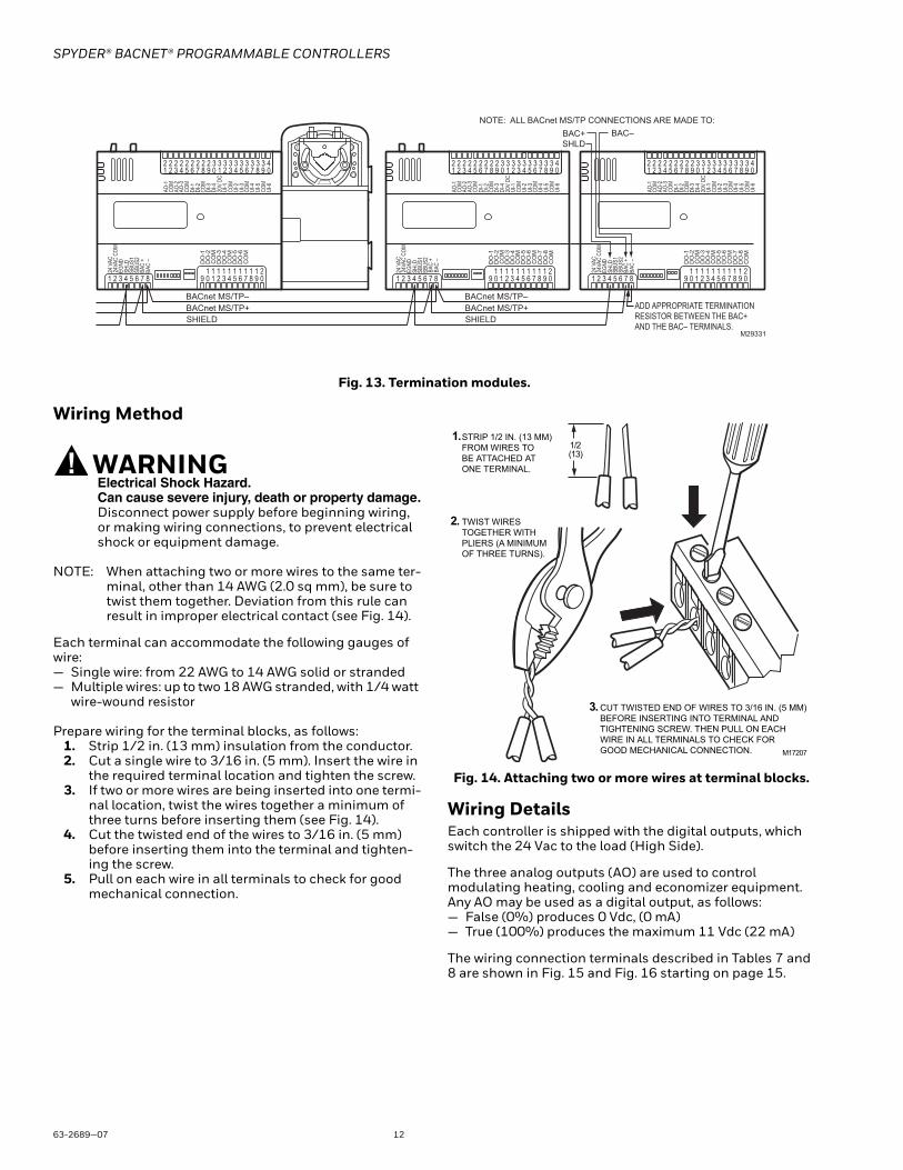
Fig. 13. Termination modules.
Wiring Method
WARNINGElectrical Shock Hazard.Can cause severe injury, death or property damage.Disconnect power supply before beginning wiring, or making wiring connections, to prevent electrical shock or equipment damage.
NOTE: When attaching two or more wires to the same ter-minal, other than 14 AWG (2.0 sq mm), be sure to twist them together. Deviation from this rule can result in improper electrical contact (see Fig. 14).
Each terminal can accommodate the following gauges of wire:— Single wire: from 22 AWG to 14 AWG solid or stranded— Multiple wires: up to two 18 AWG stranded, with 1/4 watt
wire-wound resistor
Prepare wiring for the terminal blocks, as follows:1. Strip 1/2 in. (13 mm) insulation from the conductor.2. Cut a single wire to 3/16 in. (5 mm). Insert the wire in
the required terminal location and tighten the screw.3. If two or more wires are being inserted into one termi-
nal location, twist the wires together a minimum of three turns before inserting them (see Fig. 14).
4. Cut the twisted end of the wires to 3/16 in. (5 mm) before inserting them into the terminal and tighten-ing the screw.
5. Pull on each wire in all terminals to check for good mechanical connection.
Fig. 14. Attaching two or more wires at terminal blocks.
Wiring DetailsEach controller is shipped with the digital outputs, which switch the 24 Vac to the load (High Side).
The three analog outputs (AO) are used to control modulating heating, cooling and economizer equipment. Any AO may be used as a digital output, as follows:— False (0%) produces 0 Vdc, (0 mA)— True (100%) produces the maximum 11 Vdc (22 mA)
The wiring connection terminals described in Tables 7 and 8 are shown in Fig. 15 and Fig. 16 starting on page 15.
AO-1
COM
AO-2
AO-3
COM
UI-1
COM
UI-2
UI-3
COM
UI-4
UI-5
COM
UI-6
DI-1
DI-2
COM
DI-3
20V
DCDI
-4
BAC
–BA
C +
SHLD
EGND
24 V
AC24
VAC
COM
DO
-1
CO
MD
O-2
DO
-3D
O-4
DO
-5C
OM
DO
-6C
OM
M29331
ADD APPROPRIATE TERMINATIONRESISTOR BETWEEN THE BAC+ AND THE BAC– TERMINALS.
BACnet MS/TP–
BAC+
SHLD
BAC–
NOTE: ALL BACnet MS/TP CONNECTIONS ARE MADE TO:
1 2 3 4 5 6 7 8 1 0 9 2 3 4 5 6 7 8 0 9 1 1 1 1 1 1 1 1 1 2 1
1 2 3 4 5 6 7 8 0 9 2 2 2 2 2 2 2 2 2 3 3
1 2 3 4 5 6 7 8 0 9 3 3 3 3 3 3 3 3 4
AO-1
COM
AO-2
AO-3
COM
UI-1
COM
UI-2
UI-3
COM
UI-4
UI-5
COM
UI-6
DI-1
DI-2
COM
DI-3
20V
DCDI
-4
BAC
–BA
C +
SHLD
EGND
24 V
AC24
VAC
COM
DO
-1
CO
MD
O-2
DO
-3D
O-4
DO
-5C
OM
DO
-6C
OM
1 2 3 4 5 6 7 8 1 0 9 2 3 4 5 6 7 8 0 9 1 1 1 1 1 1 1 1 1 2 1
1 2 3 4 5 6 7 8 0 9 2 2 2 2 2 2 2 2 2 3 3
1 2 3 4 5 6 7 8 0 9 3 3 3 3 3 3 3 3 4
DO
-7D
O-8
CO
M
DO
-7D
O-8
CO
M
SBUS
1SB
US2
SBUS
1SB
US2
SBUS
1SB
US2
BACnet MS/TP+
SHIELD
BACnet MS/TP–
BACnet MS/TP+
SHIELD
1/2(13)
STRIP 1/2 IN. (13 MM)
FROM WIRES TO
BE ATTACHED AT
ONE TERMINAL.
1.
2. TWIST WIRES
TOGETHER WITH
PLIERS (A MINIMUM
OF THREE TURNS).
3. CUT TWISTED END OF WIRES TO 3/16 IN. (5 MM)
BEFORE INSERTING INTO TERMINAL AND
TIGHTENING SCREW. THEN PULL ON EACH
WIRE IN ALL TERMINALS TO CHECK FOR
GOOD MECHANICAL CONNECTION. M17207
SPYDER® BACNET® PROGRAMMABLE CONTROLLERS
13 63-2689—07
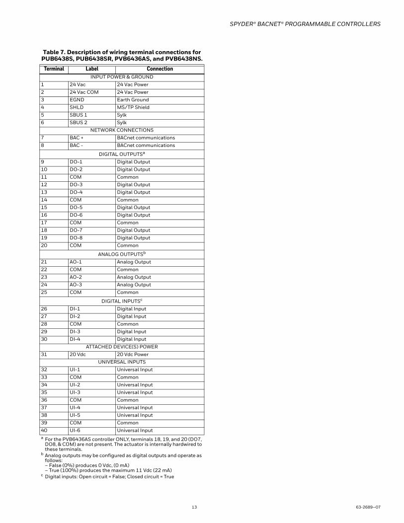
Table 7. Description of wiring terminal connections for PUB6438S, PUB6438SR, PVB6436AS, and PVB6438NS.
Terminal Label ConnectionINPUT POWER & GROUND
1 24 Vac 24 Vac Power2 24 Vac COM 24 Vac Power3 EGND Earth Ground4 SHLD MS/TP Shield5 SBUS 1 Sylk6 SBUS 2 Sylk
NETWORK CONNECTIONS7 BAC + BACnet communications8 BAC - BACnet communications
DIGITAL OUTPUTSa
9 DO-1 Digital Output10 DO-2 Digital Output11 COM Common12 DO-3 Digital Output13 DO-4 Digital Output14 COM Common15 DO-5 Digital Output16 DO-6 Digital Output17 COM Common18 DO-7 Digital Output19 DO-8 Digital Output20 COM Common
ANALOG OUTPUTSb
21 AO-1 Analog Output22 COM Common23 AO-2 Analog Output24 AO-3 Analog Output25 COM Common
DIGITAL INPUTSc
26 DI-1 Digital Input27 DI-2 Digital Input28 COM Common29 DI-3 Digital Input30 DI-4 Digital Input
ATTACHED DEVICE(S) POWER31 20 Vdc 20 Vdc Power
UNIVERSAL INPUTS32 UI-1 Universal Input33 COM Common34 UI-2 Universal Input35 UI-3 Universal Input36 COM Common37 UI-4 Universal Input38 UI-5 Universal Input39 COM Common40 UI-6 Universal Inputa For the PVB6436AS controller ONLY, terminals 18, 19, and 20 (DO7,
DO8, & COM) are not present. The actuator is internally hardwired to these terminals.
b Analog outputs may be configured as digital outputs and operate as follows:– False (0%) produces 0 Vdc, (0 mA)– True (100%) produces the maximum 11 Vdc (22 mA)
c Digital inputs: Open circuit = False; Closed circuit = True
SPYDER® BACNET® PROGRAMMABLE CONTROLLERS
63-2689—07 14
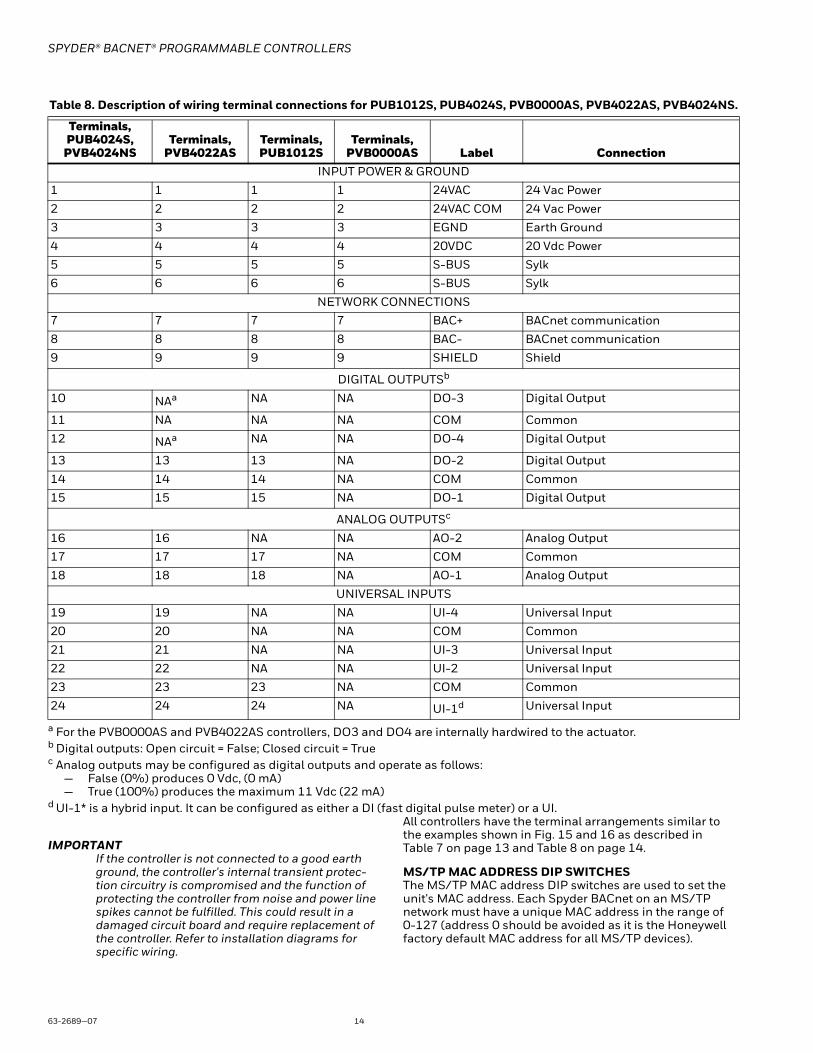
a For the PVB0000AS and PVB4022AS controllers, DO3 and DO4 are internally hardwired to the actuator.b Digital outputs: Open circuit = False; Closed circuit = Truec Analog outputs may be configured as digital outputs and operate as follows:
— False (0%) produces 0 Vdc, (0 mA)— True (100%) produces the maximum 11 Vdc (22 mA)
d UI-1* is a hybrid input. It can be configured as either a DI (fast digital pulse meter) or a UI.
IMPORTANTIf the controller is not connected to a good earth ground, the controller's internal transient protec-tion circuitry is compromised and the function of protecting the controller from noise and power line spikes cannot be fulfilled. This could result in a damaged circuit board and require replacement of the controller. Refer to installation diagrams for specific wiring.
All controllers have the terminal arrangements similar to the examples shown in Fig. 15 and 16 as described in Table 7 on page 13 and Table 8 on page 14.
MS/TP MAC ADDRESS DIP SWITCHESThe MS/TP MAC address DIP switches are used to set the unit's MAC address. Each Spyder BACnet on an MS/TP network must have a unique MAC address in the range of 0-127 (address 0 should be avoided as it is the Honeywell factory default MAC address for all MS/TP devices).
Table 8. Description of wiring terminal connections for PUB1012S, PUB4024S, PVB0000AS, PVB4022AS, PVB4024NS.
Terminals, PUB4024S,
PVB4024NSTerminals,
PVB4022ASTerminals, PUB1012S
Terminals, PVB0000AS Label Connection
INPUT POWER & GROUND
1 1 1 1 24VAC 24 Vac Power
2 2 2 2 24VAC COM 24 Vac Power
3 3 3 3 EGND Earth Ground
4 4 4 4 20VDC 20 Vdc Power
5 5 5 5 S-BUS Sylk
6 6 6 6 S-BUS Sylk
NETWORK CONNECTIONS
7 7 7 7 BAC+ BACnet communication
8 8 8 8 BAC- BACnet communication
9 9 9 9 SHIELD Shield
DIGITAL OUTPUTSb
10 NAa NA NA DO-3 Digital Output
11 NA NA NA COM Common
12 NAa NA NA DO-4 Digital Output
13 13 13 NA DO-2 Digital Output
14 14 14 NA COM Common
15 15 15 NA DO-1 Digital Output
ANALOG OUTPUTSc
16 16 NA NA AO-2 Analog Output
17 17 17 NA COM Common
18 18 18 NA AO-1 Analog Output
UNIVERSAL INPUTS
19 19 NA NA UI-4 Universal Input
20 20 NA NA COM Common
21 21 NA NA UI-3 Universal Input
22 22 NA NA UI-2 Universal Input
23 23 23 NA COM Common
24 24 24 NA UI-1d Universal Input
SPYDER® BACNET® PROGRAMMABLE CONTROLLERS
15 63-2689—07
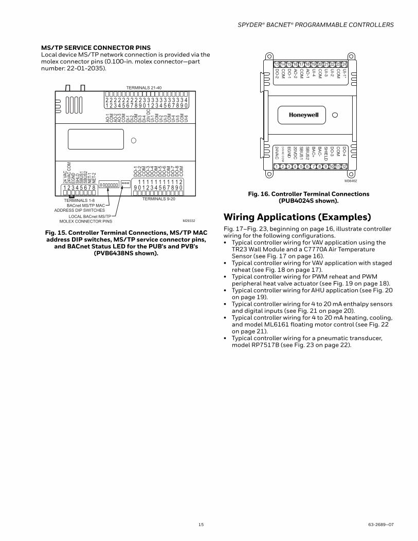
MS/TP SERVICE CONNECTOR PINSLocal device MS/TP network connection is provided via the molex connector pins (0.100-in. molex connector—part number: 22-01-2035).
Fig. 15. Controller Terminal Connections, MS/TP MAC address DIP switches, MS/TP service connector pins,
and BACnet Status LED for the PUB's and PVB's (PVB6438NS shown).
Fig. 16. Controller Terminal Connections (PUB4024S shown).
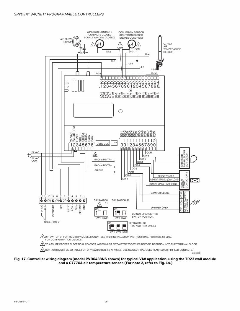
Wiring Applications (Examples)Fig. 17–Fig. 23, beginning on page 16, illustrate controller wiring for the following configurations.• Typical controller wiring for VAV application using the
TR23 Wall Module and a C7770A Air Temperature Sensor (see Fig. 17 on page 16).
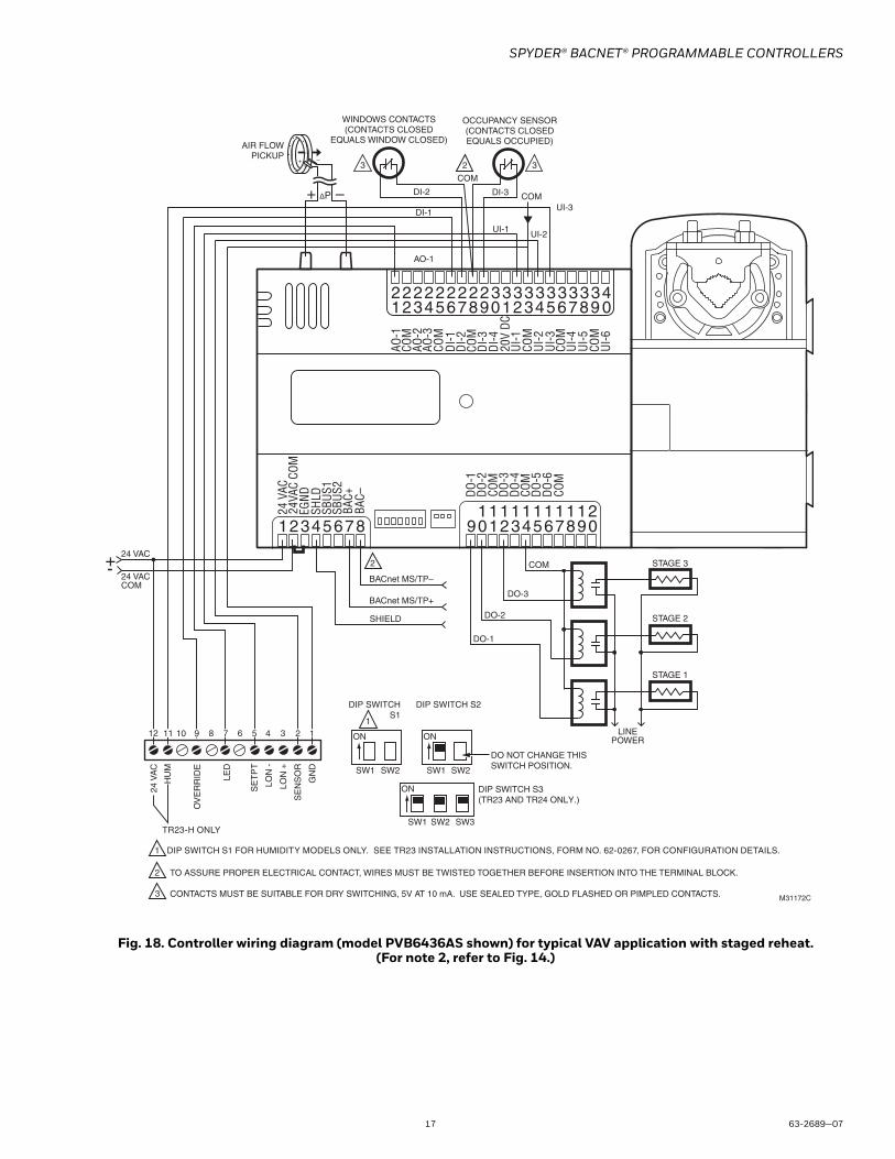
• Typical controller wiring for VAV application with staged reheat (see Fig. 18 on page 17).
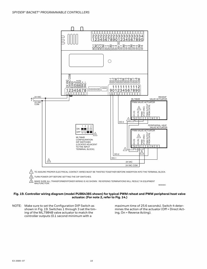
• Typical controller wiring for PWM reheat and PWM peripheral heat valve actuator (see Fig. 19 on page 18).
• Typical controller wiring for AHU application (see Fig. 20 on page 19).
• Typical controller wiring for 4 to 20 mA enthalpy sensors and digital inputs (see Fig. 21 on page 20).
• Typical controller wiring for 4 to 20 mA heating, cooling, and model ML6161 floating motor control (see Fig. 22 on page 21).
• Typical controller wiring for a pneumatic transducer, model RP7517B (see Fig. 23 on page 22).
BACnet MS/TP MACADDRESS DIP SWITCHES
TERMINALS 1-8 TERMINALS 9-20
TERMINALS 21-40
AO-1
COM
AO-2
AO-3
COM
UI-1
COM
UI-2
UI-3
COM
UI-4
UI-5
COM
UI-6
DI-1
DI-2
COM
DI-3
20V
DCDI
-4
NET-
2NE
T-1
SHLD
EGND
24 V
AC24
VAC
COM
DO
-1
CO
MD
O-2
DO
-3D
O-4
DO
-5C
OM
DO
-6C
OM
1 2 3 4 5 6 7 8 1 0 9 2 3 4 5 6 7 8 0 9 1 1 1 1 1 1 1 1 1 2 1
1 2 3 4 5 6 7 8 0 9 2 2 2 2 2 2 2 2 2 3 3
1 2 3 4 5 6 7 8 0 9 3 3 3 3 3 3 3 3 4
M29332
DO
-7D
O-8
CO
M
SBUS
1SB
US2
LOCAL BACnet MS/TP MOLEX CONNECTOR PINS
M36462
22 23 2416 17 18 19 20 2113 14 15
24VA
C
24
VAC
CO
M
EGN
D
SB
US
2
SB
US
1
BA
C+
BA
C-
SH
IELD
20VD
C
CO
M
DO
-3
DO
-4
1 2 3 4 5 6 7 8 9 10 11 12
DO
-2
CO
M
DO
-1
AO
-2
CO
M
AO
-1
UI-4
CO
M
UI-3
UI-2
CO
M
UI-1*
SPYDER® BACNET® PROGRAMMABLE CONTROLLERS
63-2689—07 16
Fig. 17. Controller wiring diagram (model PVB6438NS shown) for typical VAV application, using the TR23 wall module and a C7770A air temperature sensor. (For note 2, refer to Fig. 14.)
2
1
3
TO ASSURE PROPER ELECTRICAL CONTACT, WIRES MUST BE TWISTED TOGETHER BEFORE INSERTION INTO THE TERMINAL BLOCK.
CONTACTS MUST BE SUITABLE FOR DRY SWITCHING, 5V AT 10 mA. USE SEALED TYPE, GOLD FLASHED OR PIMPLED CONTACTS.M31169C
AO-1
DI-1UI-1
UI-2
UI-4
COM
24 VAC
24 VACCOM
+-
DO-1DO-2
DO-3DO-4 S
ER
IES
OR
PA
RA
LLE
L FA
N
CO
NTA
CTO
R
RE
HE
AT
STA
GE
C
ON
TAC
TOR
SM
L616
1 D
AM
PE
RA
CT
UAT
OR
CW
CO
MC
CW
OCCUPANCY SENSOR(CONTACTS CLOSEDEQUALS OCCUPIED)
WINDOWS CONTACTS(CONTACTS CLOSED
EQUALS WINDOW CLOSED)
DI-2
COM
2
DO-5DO-6
C7770AAIRTEMPERATURESENSOR
UI-3
COM
AIR FLOWPICKUP
ΔP
3 3
DAMPER OPEN
DAMPER CLOSE
REHEAT STAGE 1 (OR OPEN)
REHEAT STAGE 2 (OR CLOSE)
COM
REHEAT STAGE 3
DI-3
COM
COM
SBUS
1SB
US2
AO-1
COM
AO-2
AO-3
COM
UI-1
COM
UI-2
UI-3
COM
UI-4
UI-5
COM
UI-6
DI-1
DI-2
COM
DI-3
20V
DCDI
-4
SHLD
EGND
24 V
AC24
VAC
COM
DO-1
COM
DO-2
DO-3
DO-4
DO-5
COM
DO-6
COM
12345678 109 2345678 0911 1111111 21
12345678 0922 2222222 33
12345678 0933 33 33 33 4
DO-7
DO-8
COM
BAC+
BAC–
SHIELD
BACnet MS/TP+
BACnet MS/TP–
2
DIP SWITCH S3(TR23 AND TR24 ONLY.)
ON
SW1 SW2 SW3
DIP SWITCH S2
ON
SW1 SW2
DIP SWITCHS1
ON
SW1 SW2
DIP SWITCH S1 FOR HUMIDITY MODELS ONLY. SEE TR23 INSTALLATION INSTRUCTIONS, FORM NO. 62-0267, FOR CONFIGURATION DETAILS.
TR23-H ONLY
DO NOT CHANGE THIS SWITCH POSITION.
10 8 6 4 3
GN
D
SE
NS
OR
LON
+
LON
-
SE
TP
T
LED
OV
ER
RID
E
HU
M
24 V
AC
9 7 5 2 11112
1
SPYDER® BACNET® PROGRAMMABLE CONTROLLERS
17 63-2689—07
Fig. 18. Controller wiring diagram (model PVB6436AS shown) for typical VAV application with staged reheat. (For note 2, refer to Fig. 14.)
AO-1
DI-1 UI-3
UI-2UI-1
COM
COM
24 VAC
24 VACCOM
+-
DO-1
DO-2
DO-3
OCCUPANCY SENSOR(CONTACTS CLOSEDEQUALS OCCUPIED)
WINDOWS CONTACTS(CONTACTS CLOSED
EQUALS WINDOW CLOSED)
DI-2
2
AIR FLOWPICKUP
ΔP
3 3
DI-3
COM
LINEPOWER
STAGE 1
STAGE 2
STAGE 3
AO-1
COM
AO-2
AO-3
COM
UI-1
COM
UI-2
UI-3
COM
UI-4
UI-5
COM
UI-6
DI-1
DI-2
COM
DI-3
20V
DCDI
-4
BAC–
BAC+
SHLD
EGND
24 V
AC24
VAC
COM
DO-1
COM
DO-2
DO-3
DO-4
DO-5
COM
DO-6
COM
12345678 109 2345678 0911 1111111 21
12345678 0922 2222222 33
12345678 0933 33 33 33 4
SBUS
1SB
US2
SHIELD
BACnet MS/TP+
BACnet MS/TP–
2
2
1
3
TO ASSURE PROPER ELECTRICAL CONTACT, WIRES MUST BE TWISTED TOGETHER BEFORE INSERTION INTO THE TERMINAL BLOCK.
CONTACTS MUST BE SUITABLE FOR DRY SWITCHING, 5V AT 10 mA. USE SEALED TYPE, GOLD FLASHED OR PIMPLED CONTACTS. M31172C
DIP SWITCH S3(TR23 AND TR24 ONLY.)
ON
SW1 SW2 SW3
DIP SWITCH S2
ON
SW1 SW2
DIP SWITCHS1
ON
SW1 SW2
DIP SWITCH S1 FOR HUMIDITY MODELS ONLY. SEE TR23 INSTALLATION INSTRUCTIONS, FORM NO. 62-0267, FOR CONFIGURATION DETAILS.
TR23-H ONLY
DO NOT CHANGE THIS SWITCH POSITION.
10 8 6 4 3
GN
D
SE
NS
OR
LON
+
LON
-
SE
TP
T
LED
OV
ER
RID
E
HU
M
24 V
AC
9 2 112 57111
SPYDER® BACNET® PROGRAMMABLE CONTROLLERS
63-2689—07 18
Fig. 19. Controller wiring diagram (model PUB6438S shown) for typical PWM reheat and PWM peripheral heat valve actuator. (For note 2, refer to Fig. 14.)
NOTE: Make sure to set the Configuration DIP Switch as shown in Fig. 19. Switches 1 through 3 set the tim-ing of the ML7984B valve actuator to match the controller outputs (0.1 second minimum with a
maximum time of 25.6 seconds). Switch 4 deter-mines the action of the actuator (Off = Direct Act-ing, On = Reverse Acting).
1 2 3 4
2
ON
OFF
ML7984B CONFIGURATION DIP SWITCHES(LOCATED ADJACENT TO THE INPUTTERMINAL BLOCK)
1
1
2
TO ASSURE PROPER ELECTRICAL CONTACT, WIRES MUST BE TWISTED TOGETHER BEFORE INSERTION INTO THE TERMINAL BLOCK.
TURN POWER OFF BEFORE SETTING THE DIP SWITCHES.
MAKE SURE ALL TRANSFORMER/POWER WIRING IS AS SHOWN: REVERSING TERMINATIONS WILL RESULT IN EQUIPMENT MALFUNCTION. M29335C
24 VAC
24 VACCOM
+-
DO-1
DO-2
DO-3
3
3
24 VAC COM
1
1
24 (
H)
24 (
N)
PW
M
(H 2
4 V
AC
)
PW
M O
UTP
UT
FRO
M C
NTR
L
PWM VALVE ACTUATOR
ML7984B
T6 T5 C B W R
REHEAT VALVE ACTUATOR
24 (
H)
24 (
N)
PW
M
(H 2
4 V
AC
)
PW
M O
UTP
UT
FRO
M C
NTR
L
PWM VALVE ACTUATOR
T6 T5 C B W R
PERIPHERAL HEAT VALVE ACTUATOR
24 VAC
3
3
AO-1
COM
AO-2
AO-3
COM
UI-1
COM
UI-2
UI-3
COM
UI-4
UI-5
COM
UI-6
DI-1
DI-2
COM
DI-3
20V
DCDI
-4
BAC–
BAC+
SHLD
EGND
24 V
AC24
VAC
COM
DO-1
COM
DO-2
DO-3
DO-4
DO-5
COM
DO-6
COM
12345678 109 2345678 0911 1111111 21
12345678 0922 2222222 33
12345678 0933 33 33 33 4
DO-7
DO-8
COM
SBUS
1SB
US2
SPYDER® BACNET® PROGRAMMABLE CONTROLLERS
19 63-2689—07
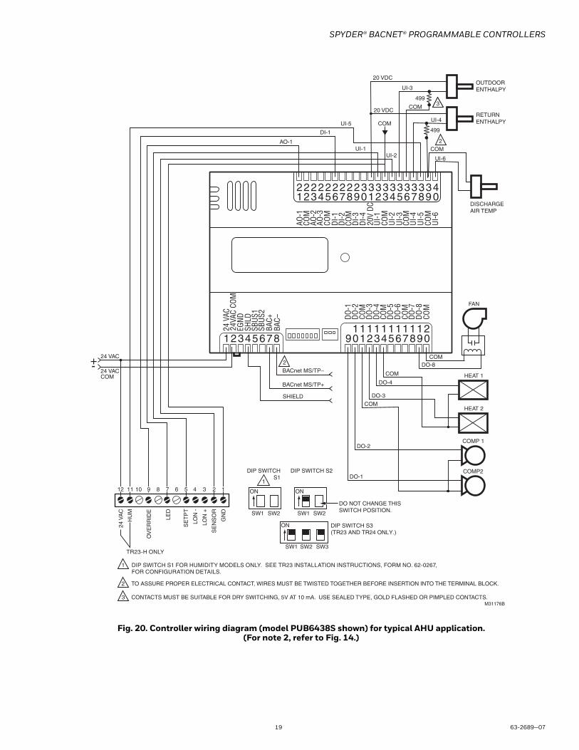
Fig. 20. Controller wiring diagram (model PUB6438S shown) for typical AHU application.(For note 2, refer to Fig. 14.)
2
AO-1
DI-1
UI-2UI-1
UI-5
24 VAC
24 VACCOM
+-
DO-1
DO-2
DO-3
DO-4
DO-8
UI-3
COM
COM
COM
COM
DISCHARGE AIR TEMP
COM
COM
UI-6
OUTDOORENTHALPY
RETURNENTHALPY
20 VDC
20 VDC
3499
2
COMP2
COMP 1
HEAT 2
HEAT 1
FAN
UI-4
499
SBUS
1SB
US2
AO-1
COM
AO-2
AO-3
COM
UI-1
COM
UI-2
UI-3
COM
UI-4
UI-5
COM
UI-6
DI-1
DI-2
COM
DI-3
20V
DCDI
-4
SHLD
EGND
24 V
AC24
VAC
COM
DO-1
COM
DO-2
DO-3
DO-4
DO-5
COM
DO-6
COM
12345678 109 2345678 0911 1111111 21
12345678 0922 2222222 33
12345678 0933 33 33 33 4
DO-7
DO-8
COM
BAC+
BAC–
SHIELD
BACnet MS/TP+
BACnet MS/TP–
2
1
3
TO ASSURE PROPER ELECTRICAL CONTACT, WIRES MUST BE TWISTED TOGETHER BEFORE INSERTION INTO THE TERMINAL BLOCK.
CONTACTS MUST BE SUITABLE FOR DRY SWITCHING, 5V AT 10 mA. USE SEALED TYPE, GOLD FLASHED OR PIMPLED CONTACTS.M31176B
DIP SWITCH S3(TR23 AND TR24 ONLY.)
ON
SW1 SW2 SW3
DIP SWITCH S2
ON
SW1 SW2
DIP SWITCHS1
ON
SW1 SW2
DIP SWITCH S1 FOR HUMIDITY MODELS ONLY. SEE TR23 INSTALLATION INSTRUCTIONS, FORM NO. 62-0267, FOR CONFIGURATION DETAILS.
TR23-H ONLY
DO NOT CHANGE THIS SWITCH POSITION.
10 8 6 4 3
GN
D
SE
NS
OR
LON
+
LON
-
SE
TP
T
LED
OV
ER
RID
E
HU
M
24 V
AC
12 11 9 7 5 2 11
SPYDER® BACNET® PROGRAMMABLE CONTROLLERS
63-2689—07 20
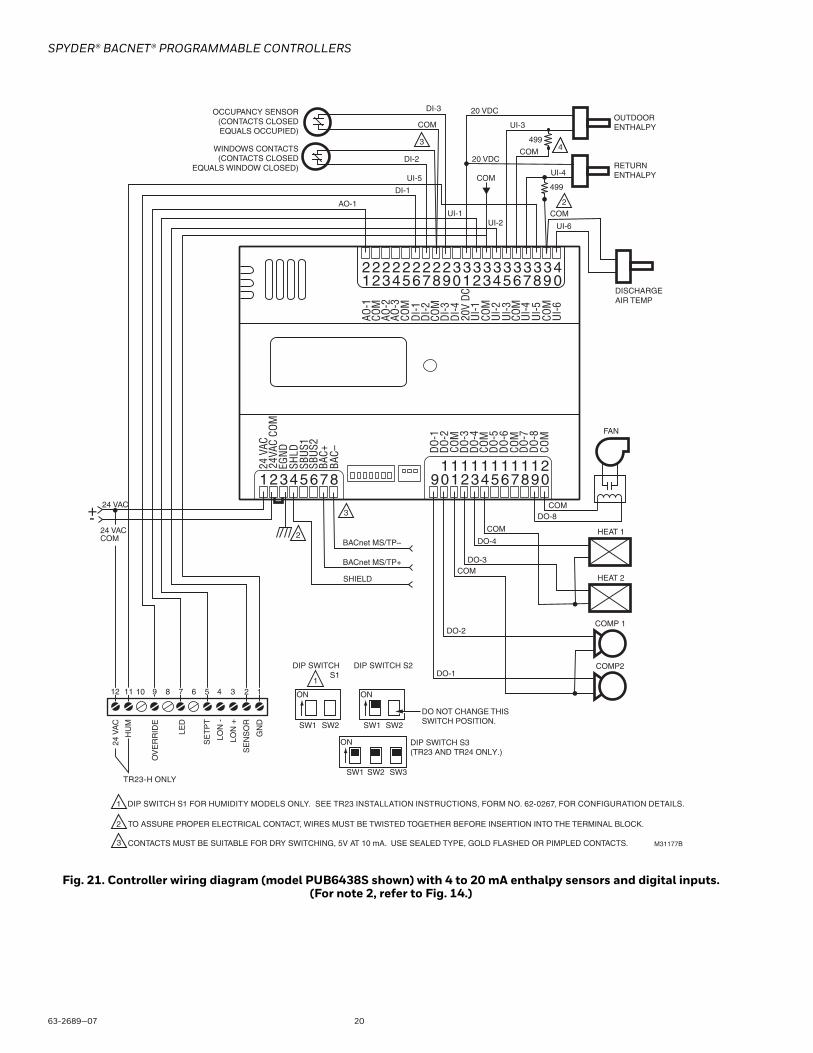
Fig. 21. Controller wiring diagram (model PUB6438S shown) with 4 to 20 mA enthalpy sensors and digital inputs. (For note 2, refer to Fig. 14.)
AO-1
DI-1
UI-2UI-1
UI-5 COM
2
1
3
TO ASSURE PROPER ELECTRICAL CONTACT, WIRES MUST BE TWISTED TOGETHER BEFORE INSERTION INTO THE TERMINAL BLOCK.
CONTACTS MUST BE SUITABLE FOR DRY SWITCHING, 5V AT 10 mA. USE SEALED TYPE, GOLD FLASHED OR PIMPLED CONTACTS.
DIP SWITCH S3(TR23 AND TR24 ONLY.)
ON
SW1 SW2 SW3
DIP SWITCH S2
ON
SW1 SW2
DIP SWITCHS1
ON
SW1 SW2
DIP SWITCH S1 FOR HUMIDITY MODELS ONLY. SEE TR23 INSTALLATION INSTRUCTIONS, FORM NO. 62-0267, FOR CONFIGURATION DETAILS.
TR23-H ONLY
DO NOT CHANGE THIS SWITCH POSITION.
10 8 6 4 3
GN
D
SE
NS
OR
LON
+
LON
-
SE
TP
T
LED
OV
ER
RID
E
HU
M
24 V
AC
12 11 9 7 5 2 11
2
3
M31177B
24 VAC+-
DO-1
DO-2
DO-3
DO-4
DO-8
UI-3
COM
COM
COM
COM
DISCHARGE AIR TEMP
COM
UI-6
OUTDOORENTHALPY
RETURNENTHALPY
20 VDC
20 VDC
4 499
2
COMP2
COMP 1
HEAT 2
HEAT 1
FAN
UI-4
499
OCCUPANCY SENSOR(CONTACTS CLOSEDEQUALS OCCUPIED)
WINDOWS CONTACTS(CONTACTS CLOSED
EQUALS WINDOW CLOSED)
3
DI-2
COM
DI-3
AO-1
COM
AO-2
AO-3
COM
UI-1
COM
UI-2
UI-3
COM
UI-4
UI-5
COM
UI-6
DI-1
DI-2
COM
DI-3
20V
DCDI
-4
SHLD
EGND
24 V
AC24
VAC
COM
DO-1
COM
DO-2
DO-3
DO-4
DO-5
COM
DO-6
COM
12345678 109 2345678 0911 1111111 21
12345678 0922 2222222 33
12345678 0933 33 33 33 4
DO-7
DO-8
COM
SBUS
1SB
US2
BAC–
BAC+
SHIELD
BACnet MS/TP+
BACnet MS/TP–
24 VACCOM
SPYDER® BACNET® PROGRAMMABLE CONTROLLERS
21 63-2689—07
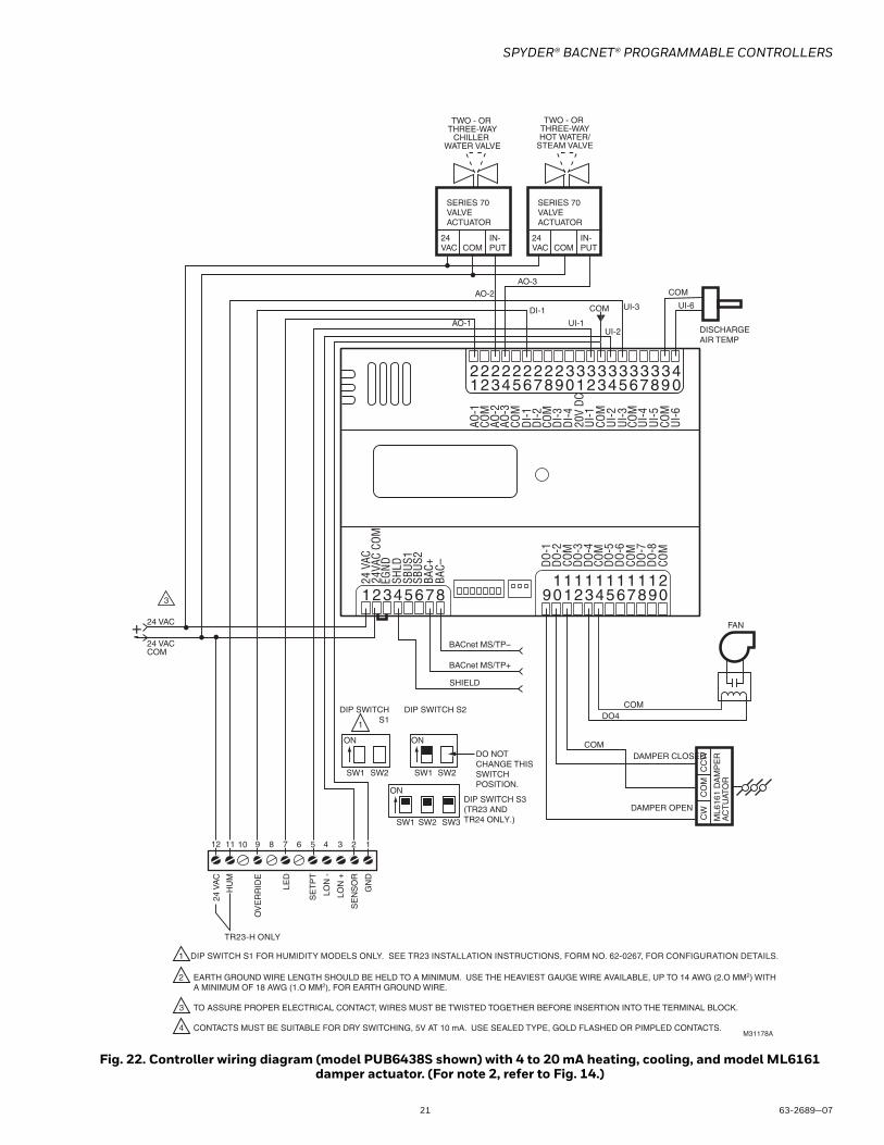
Fig. 22. Controller wiring diagram (model PUB6438S shown) with 4 to 20 mA heating, cooling, and model ML6161 damper actuator. (For note 2, refer to Fig. 14.)
COM
COM
DO4
COM
UI-6
FAN
SERIES 70 VALVE ACTUATOR
24VAC
IN-PUTCOM
TWO - OR THREE-WAY
CHILLER WATER VALVE
SERIES 70 VALVE ACTUATOR
24VAC
IN-PUTCOM
TWO - OR THREE-WAYHOT WATER/
STEAM VALVE
AO-3
3
ML6
161
DA
MP
ER
AC
TU
ATO
R
CW
CO
MC
CW
DAMPER OPEN
DAMPER CLOSED
DISCHARGE AIR TEMP
AO-2
AO-1UI-2
UI-1
DI-1 UI-3
AO-1
COM
AO-2
AO-3
COM
UI-1
COM
UI-2
UI-3
COM
UI-4
UI-5
COM
UI-6
DI-1
DI-2
COM
DI-3
20V
DCDI
-4
24 V
AC24
VAC
COM
DO-1
COM
DO-2
DO-3
DO-4
DO-5
COM
DO-6
COM
12345678 109 2345678 0911 1111111 21
12345678 0922 2222222 33
12345678 0933 33 33 33 4
DO-7
DO-8
COM
BAC–
BAC+
SHIELD
BACnet MS/TP+
BACnet MS/TP–
SHLD
EGND
SBUS
1SB
US2
2
1
3
EARTH GROUND WIRE LENGTH SHOULD BE HELD TO A MINIMUM. USE THE HEAVIEST GAUGE WIRE AVAILABLE, UP TO 14 AWG (2.O MM2) WITH A MINIMUM OF 18 AWG (1.O MM2), FOR EARTH GROUND WIRE.
TO ASSURE PROPER ELECTRICAL CONTACT, WIRES MUST BE TWISTED TOGETHER BEFORE INSERTION INTO THE TERMINAL BLOCK.
CONTACTS MUST BE SUITABLE FOR DRY SWITCHING, 5V AT 10 mA. USE SEALED TYPE, GOLD FLASHED OR PIMPLED CONTACTS.M31178A
4
DIP SWITCH S3(TR23 ANDTR24 ONLY.)
ON
SW1 SW2 SW3
DIP SWITCH S2
ON
SW1 SW2
DIP SWITCHS1
ON
SW1 SW2
DIP SWITCH S1 FOR HUMIDITY MODELS ONLY. SEE TR23 INSTALLATION INSTRUCTIONS, FORM NO. 62-0267, FOR CONFIGURATION DETAILS.
TR23-H ONLY
DO NOTCHANGE THIS SWITCHPOSITION.
10 8 6 4 3
GN
D
SE
NS
OR
LON
+
LON
-
SE
TP
T
LED
OV
ER
RID
E
HU
M
24 V
AC
9
24 VAC
24 VACCOM
+-
1
COM
2571112
1
SPYDER® BACNET® PROGRAMMABLE CONTROLLERS
63-2689—07 22
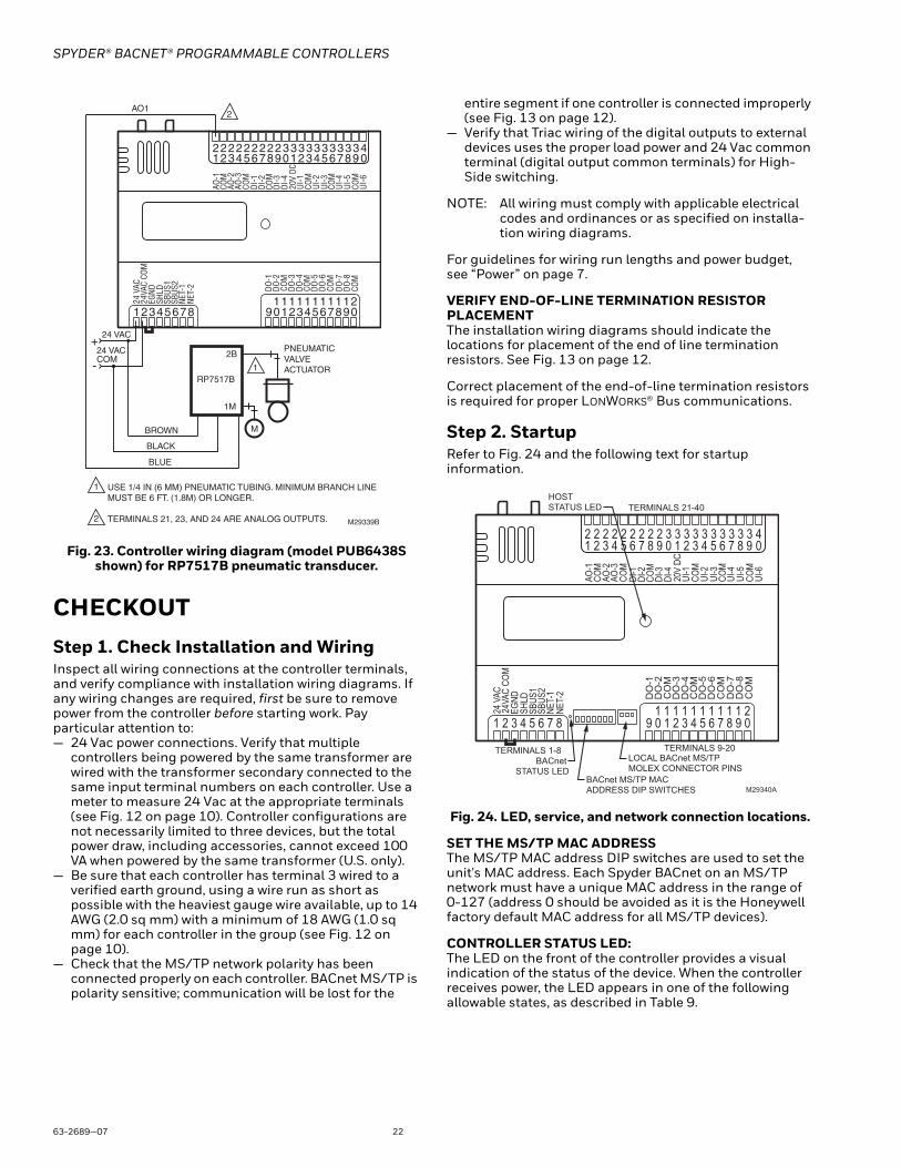
Fig. 23. Controller wiring diagram (model PUB6438S shown) for RP7517B pneumatic transducer.
CHECKOUTStep 1. Check Installation and WiringInspect all wiring connections at the controller terminals, and verify compliance with installation wiring diagrams. If any wiring changes are required, first be sure to remove power from the controller before starting work. Pay particular attention to:— 24 Vac power connections. Verify that multiple
controllers being powered by the same transformer are wired with the transformer secondary connected to the same input terminal numbers on each controller. Use a meter to measure 24 Vac at the appropriate terminals (see Fig. 12 on page 10). Controller configurations are not necessarily limited to three devices, but the total power draw, including accessories, cannot exceed 100 VA when powered by the same transformer (U.S. only).
— Be sure that each controller has terminal 3 wired to a verified earth ground, using a wire run as short as possible with the heaviest gauge wire available, up to 14 AWG (2.0 sq mm) with a minimum of 18 AWG (1.0 sq mm) for each controller in the group (see Fig. 12 on page 10).
— Check that the MS/TP network polarity has been connected properly on each controller. BACnet MS/TP is polarity sensitive; communication will be lost for the
entire segment if one controller is connected improperly (see Fig. 13 on page 12).
— Verify that Triac wiring of the digital outputs to external devices uses the proper load power and 24 Vac common terminal (digital output common terminals) for High-Side switching.
NOTE: All wiring must comply with applicable electrical codes and ordinances or as specified on installa-tion wiring diagrams.
For guidelines for wiring run lengths and power budget, see “Power” on page 7.
VERIFY END-OF-LINE TERMINATION RESISTOR PLACEMENTThe installation wiring diagrams should indicate the locations for placement of the end of line termination resistors. See Fig. 13 on page 12.
Correct placement of the end-of-line termination resistors is required for proper LONWORKS® Bus communications.
Step 2. StartupRefer to Fig. 24 and the following text for startup information.
Fig. 24. LED, service, and network connection locations.
SET THE MS/TP MAC ADDRESSThe MS/TP MAC address DIP switches are used to set the unit's MAC address. Each Spyder BACnet on an MS/TP network must have a unique MAC address in the range of 0-127 (address 0 should be avoided as it is the Honeywell factory default MAC address for all MS/TP devices).
CONTROLLER STATUS LED:The LED on the front of the controller provides a visual indication of the status of the device. When the controller receives power, the LED appears in one of the following allowable states, as described in Table 9.
AO-1
COM
AO-2
AO-3
COM
UI-1
COM
UI-2
UI-3
COM
UI-4
UI-5
COM
UI-6
DI-1
DI-2
COM
DI-3
20V
DCDI
-4
NET-
2NE
T-1
SHLD
EGND
24 V
AC24
VAC
COM
DO-1
COM
DO-2
DO-3
DO-4
DO-5
COM
DO-6
COM
12345678 109 2345678 0911 1111111 21
12345678 0922 2222222 33
12345678 0933 33 33 33 4
M29339B
24 VAC
AO1
24 VAC COM
1
2
USE 1/4 IN (6 MM) PNEUMATIC TUBING. MINIMUM BRANCH LINEMUST BE 6 FT. (1.8M) OR LONGER.
TERMINALS 21, 23, AND 24 ARE ANALOG OUTPUTS.
+
-
BLUE
BLACK
BROWN
PNEUMATICVALVE ACTUATOR
RP7517B
1M
2B
M
2
1
DO-7
DO-8
COM
SBUS
1SB
US2
BACnet MS/TP MACADDRESS DIP SWITCHES
TERMINALS 1-8 TERMINALS 9-20
TERMINALS 21-40
AO-1
COM
AO-2
AO-3
COM
UI-1
COM
UI-2
UI-3
COM
UI-4
UI-5
COM
UI-6
DI-1
DI-2
COM
DI-3
20V
DCDI
-4
NET-
2NE
T-1
SHLD
EGND
24 V
AC24
VAC
COM
DO
-1
CO
MD
O-2
DO
-3D
O-4
DO
-5C
OM
DO
-6C
OM
1 2 3 4 5 6 7 8 1 0 9 2 3 4 5 6 7 8 0 9 1 1 1 1 1 1 1 1 1 2 1
1 2 3 4 5 6 7 8 0 9 2 2 2 2 2 2 2 2 2 3 3
1 2 3 4 5 6 7 8 0 9 3 3 3 3 3 3 3 3 4
M29340A
HOSTSTATUS LED
DO
-7D
O-8
CO
M
SBUS
1SB
US2
BACnet STATUS LED
LOCAL BACnet MS/TP MOLEX CONNECTOR PINS
SPYDER® BACNET® PROGRAMMABLE CONTROLLERS
23 63-2689—07
Table 9. Status LED States.
BACNET STATUS LED:The LED on the front of the controller, between the BACnet MS/TP terminals and MAC Address DIP Switches, provides a visual indication of the BACnet MS/TP communication status. When the controller receives power, the LED appears in one of the following allowable states, as described in Table 10.
Table 10. BACnet Status LED States.
Step 3. Checkout CompletionAt this point the controller is installed and powered. To complete the checkout, the NIAGARA FRAMEWORK® application (run on a PC) is used to configure the I/O and functions of the controller. Refer to the Programming Tool User Guide, form no. 63-2662, for controller configuration and programming details.
CONTROLLER REPLACEMENTThere are no serviceable or repairable parts inside the controller.
WARNINGFire, Explosion, or Electrical Shock Hazard.Can cause severe injury, death or property damage.Do not attempt to modify the physical or electrical characteristics of this device in any way. Replace the controller if troubleshooting indicates a malfunction.
WARNINGElectrical Shock Hazard.Can cause severe injury, death or property damage.Disconnect power supply before beginning controller replacement to prevent electrical shock or equipment damage.
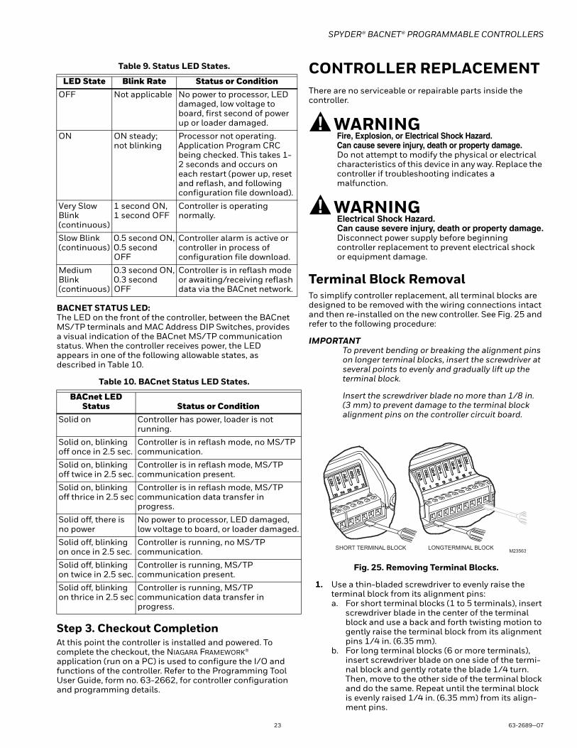
Terminal Block RemovalTo simplify controller replacement, all terminal blocks are designed to be removed with the wiring connections intact and then re-installed on the new controller. See Fig. 25 and refer to the following procedure:
IMPORTANTTo prevent bending or breaking the alignment pins on longer terminal blocks, insert the screwdriver at several points to evenly and gradually lift up the terminal block.
Insert the screwdriver blade no more than 1/8 in. (3 mm) to prevent damage to the terminal block alignment pins on the controller circuit board.
Fig. 25. Removing Terminal Blocks.
1. Use a thin-bladed screwdriver to evenly raise the terminal block from its alignment pins:a. For short terminal blocks (1 to 5 terminals), insert
screwdriver blade in the center of the terminal block and use a back and forth twisting motion to gently raise the terminal block from its alignment pins 1/4 in. (6.35 mm).
b. For long terminal blocks (6 or more terminals), insert screwdriver blade on one side of the termi-nal block and gently rotate the blade 1/4 turn. Then, move to the other side of the terminal block and do the same. Repeat until the terminal block is evenly raised 1/4 in. (6.35 mm) from its align-ment pins.
LED State Blink Rate Status or ConditionOFF Not applicable No power to processor, LED
damaged, low voltage to board, first second of power up or loader damaged.
ON ON steady; not blinking
Processor not operating. Application Program CRC being checked. This takes 1-2 seconds and occurs on each restart (power up, reset and reflash, and following configuration file download).
Very Slow Blink(continuous)
1 second ON,1 second OFF
Controller is operating normally.
Slow Blink(continuous)
0.5 second ON,0.5 second OFF
Controller alarm is active or controller in process of configuration file download.
Medium Blink(continuous)
0.3 second ON,0.3 second OFF
Controller is in reflash mode or awaiting/receiving reflash data via the BACnet network.
BACnet LED Status Status or Condition
Solid on Controller has power, loader is not running.
Solid on, blinking off once in 2.5 sec.
Controller is in reflash mode, no MS/TP communication.
Solid on, blinking off twice in 2.5 sec.
Controller is in reflash mode, MS/TP communication present.
Solid on, blinking off thrice in 2.5 sec
Controller is in reflash mode, MS/TP communication data transfer in progress.
Solid off, there is no power
No power to processor, LED damaged, low voltage to board, or loader damaged.
Solid off, blinking on once in 2.5 sec.
Controller is running, no MS/TP communication.
Solid off, blinking on twice in 2.5 sec.
Controller is running, MS/TP communication present.
Solid off, blinking on thrice in 2.5 sec
Controller is running, MS/TP communication data transfer in progress.
SHORT TERMINAL BLOCK LONGTERMINAL BLOCKM23563
SPYDER® BACNET® PROGRAMMABLE CONTROLLERS
Automation and Control SolutionsHoneywell International Inc.
1985 Douglas Drive North
Golden Valley, MN 55422
customer.honeywell.com
® U.S. Registered Trademark© 2016 Honeywell International Inc.63-2689—07 M.S. Rev. 08-16 Printed in United States
By using this Honeywell literature, you agree that Honeywell will have no liability for any damages arising out of your use or mod-ification to, the literature. You will defend and indemnify Honeywell, its affiliates and subsidiaries, from and against any liability, cost, or damages, including attorneys’ fees, arising out of, or resulting from, any modification to the literature by you.
2. Once the terminal block is raised 1/4 in. (6.35 mm) from its alignment pins, grasp the terminal block at its center (for long terminal blocks grasp it at each end) and pull it straight up.
Controller Replacement (PVB0000AS, PVB4022AS and PVB6436AS)For PVB0000AS, PVB4022AS and PVB6436AS controllers, which are hard-wired to an actuator, perform the following actions to replace the complete assembly (controller and actuator):
1. Remove all power from the controller.2. Remove the two air flow pickup connections from
the pressure sensor.3. Remove the terminal blocks (See “Terminal Block
Removal” ).4. Remove the old controller and actuator assembly
from its mounting.• Loosen the two bolts on the actuator clamp to
release the actuator from the shaft.• Remove the controller’s mounting screws.• Gently pull the controller and actuator assembly
straight out, until the assembly is clear of the actuator shaft.
5. Mount the new controller and actuator assembly (See “Installation” on page 3.).
6. Reconnect the two air flow pickup tubes to the pres-sure sensor (See “Piping (PVB0000AS, PVB4022AS, PVB4024NS, PVB6436AS and PVB6438NS)” on page 7.).
7. Replace the terminal blocks:• Insert each terminal block onto its alignment
pins.• Press straight down to firmly seat it. • Repeat for each terminal block.
8. Restore power to the controller.9. Perform “Checkout” on page 22.
Controller Replacement (PVB4024NS and PVB6438NS)Perform the following to replace the PVB4024NS and PVB6438NS controllers:
1. Remove all power from the controller.2. Remove the two air flow pickup connections from
the pressure sensor.3. Remove the terminal blocks.
• See “Terminal Block Removal” on page 23.
4. Remove the old controller from its mounting.
IMPORTANT (FOR CONTROLLERS MOUNTED TO A DIN RAIL):
1. Push straight up from the bottom to release the top pins.
2. Rotate the top of the controller outwards to release the bottom flex connectors (see Fig. 8 on page 7).
5. Mount the new controller. • See “Installation” on page 3.
6. Reconnect the two air flow pickup tubes to the pres-sure sensor (See “Piping (PVB0000AS, PVB4022AS, PVB4024NS, PVB6436AS and PVB6438NS)” on page 7.).
7. Replace the terminal blocks:• Insert each terminal block onto its alignment
pins.• Press straight down to firmly seat it. • Repeat for each terminal block.
8. Restore power to the controller.9. Perform “Checkout” on page 22.
Controller Replacement (PUB1012S, PUB4024S, PUB6438S and PUB6438SR)Perform the following to replace the PUB1012S, PUB4024S PUB6438S and PUB6438SR controllers:
1. Remove all power from the controller.2. Remove the terminal blocks (See “Terminal Block
Removal” on page 23.).3. Remove the old controller from its mounting.
IMPORTANT (FOR CONTROLLERS MOUNTED TO A DIN RAIL):
1. Push straight up from the bottom to release the top pins.
2. Rotate the top of the controller outwards to release the bottom flex connectors (see Fig. 8 on page 7).
4. Mount the new controller. (See “Installation” on page 3.)
5. Replace the terminal blocks:• Insert each terminal block onto its alignment
pins.• Press straight down to firmly seat it. • Repeat for each terminal block.
6. Restore power to the controller.7. Perform “Checkout” on page 22.
BACnet® is a registered trademark of ASHRAE. BTL® is a registered trademark of the BACnet International.NIAGARA FRAMEWORK® and the Niagara framework logo are registered trademarks of Tridium, Inc.