sr-wms wall mount series fully assembled rack with …
TRANSCRIPT
© 2018 StrongTM
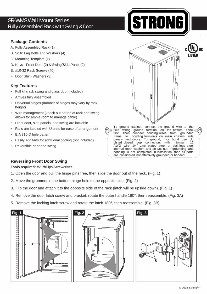
SR-WMS Wall Mount SeriesFully Assembled Rack with Swing & Door
Package ContentsA. Fully Assembled Rack (1)B. 5/16” Lag Bolts and Washers (4)C. Mounting Template (1)D. Keys - Front Door (2) & Swing/Side Panel (2)E. #10-32 Rack Screws (40)F. Door Shim Washers (3)
Key Features• Full kit (rack swing and glass door included)• Arrives fully assembled• Universal hinges (number of hinges may vary by rack
height)• Wire management (knock out on top of rack and swing
allows for ample room to manage cable)• Front door, side panels, and swing are lockable• Rails are labeled with U units for ease of arrangement• EIA 310-D hole pattern• Easily add fans for additional cooling (not included)• Reversible door and swing
To ground cabinet, connect the ground wire to the field wiring ground terminal on the bottom panel first. Then connect bonding wires from grounded frame to bonding terminals on main chassis, side panels and doors. To ground, or bond use UL Listed closed loop connectors with minimum 12 AWG wire 1/4” zinc plated steel or stainless steel internal tooth washer, and an M6 nut. If grounding and bonding is not completed in installation, then all parts are considered not effectively grounded or bonded.
Reversing Front Door SwingTools required: #2 Phillips Screwdriver
1. Open the door and pull the hinge pins free, then slide the door out of the rack. (Fig. 1)
2. Move the grommet in the bottom hinge hole to the opposite side. (Fig. 2)
3. Flip the door and attach it to the opposite side of the rack (latch will be upside down). (Fig. 1)
4. Remove the door latch screw and bracket, rotate the outer handle 180°, then reassemble. (Fig. 3A)
5. Remove the locking latch screw and rotate the latch 180°, then reassemble. (Fig. 3B)
Fig. 3
A
B
Fig. 2Fig. 1

Reversing Rear Swing DirectionTools required: #2 Phillips Screwdriver, 1/4” drive ratchet wrench with 3” extension, 10mm standard depth socket, 10mm open-ended wrench, adjustable wrench or pliers
1. Using the included key, unlock the latch on the rear swing frame and remove the frame from the rack.
2. Using a 10mm wrench, loosen the alignment spikes from one side of the rack and move them to the corre-sponding holes on the opposite side. (Fig. 4)
3. Using a 10mm socket wrench with a 3” extension, loosen the hinge nuts from the inside of the rack, taking care not to lose the lock washers behind the nuts. (Fig. 5)
4. Reattach the hinges to the opposite side, making sure to keep the pins pointed down.
5. Move on to the rear swing frame. Move the hinges to the opposite side (same steps as rack).
6. Using a #2 Phillips screwdriver, remove the arm from the latch, then remove the lock ring, using pliers or an adjustable wrench as needed.
7. Install the latch into the opposite mounting hole. Note the latching arm orientation in the figure. The latch ro-tates up or down depending on which side it is installed in.
Fig. 4
Fig. 4 Fig. 4
Fig. 5
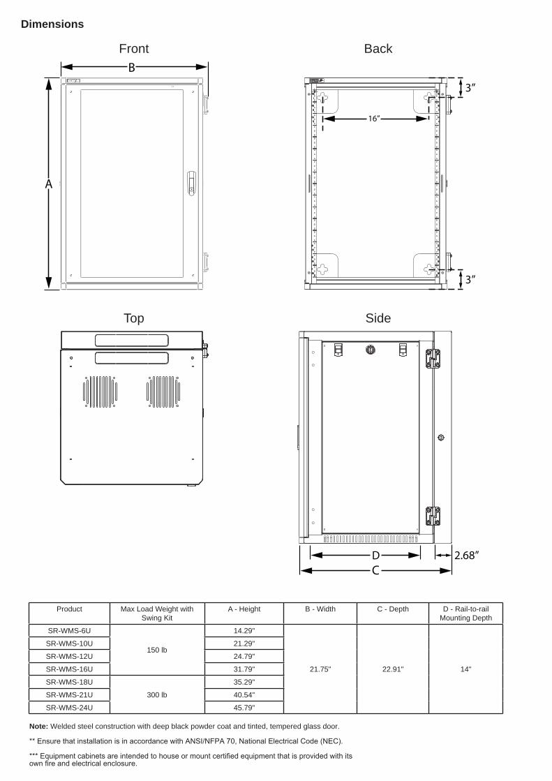
Product Max Load Weight with Swing Kit
A - Height B - Width C - Depth D - Rail-to-rail Mounting Depth
SR-WMS-6U
150 lb
14.29"
21.75" 22.91" 14"
SR-WMS-10U 21.29"
SR-WMS-12U 24.79"
SR-WMS-16U 31.79"
SR-WMS-18U
300 lb
35.29"
SR-WMS-21U 40.54"
SR-WMS-24U 45.79"
Note: Welded steel construction with deep black powder coat and tinted, tempered glass door.
** Ensure that installation is in accordance with ANSI/NFPA 70, National Electrical Code (NEC).
*** Equipment cabinets are intended to house or mount certified equipment that is provided with its own fire and electrical enclosure.
Top
Front Back
Side
A
B
16”
3”
3”
2.68”DC
Dimensions
© 2018 Strong™ 180821-0425
Lifetime Limited WarrantyAll StrongTM products have a Lifetime Limited Warranty. This warranty includes parts and labor repairs on all components found to be defective in material or workmanship under normal conditions of use. This warranty shall not apply to products that have been abused, modified, or disassembled. Products to be repaired under this warranty must be returned to Strong or a designated service center with prior notification and an assigned return authorization number (RA).
For Technical Support: 1.866.838.5052