sri unmanned aircraft systems - polarpower.orgpolarpower.org/ptc/2016_pdf/ptc2016_huff.pdf · sri...
TRANSCRIPT

SRI Unmanned Aircraft Systems Michael HuffResearch EngineerAdvanced Technology & Systems DivisionSurveillance Systems Group: Advanced ISR
SRI International333 Ravenswood Ave. Menlo Park, CA [email protected]
Polar Technology Conference, 2016

Benefits of Small Unmanned Aircraft Systems
• UAVs are rapidly being adopted in a very diverse set of fields for the following reasons:– Low-cost– Transportable– Fully customizable/ programmable– Flexible payload/mission– Multi-aircraft missions– Becoming easier to fly
• Polar applications may include:– Sea ice monitoring– Navigational aid for sea vessels– Search and rescue support– Wildlife surveying– Wildlife habitat assessments– Mapping / photography (mulispectral)– Inspecting the roofs of buildings
2
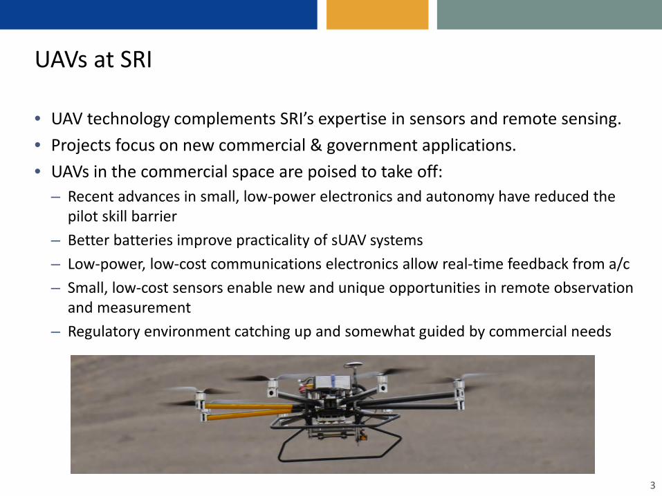
UAVs at SRI
• UAV technology complements SRI’s expertise in sensors and remote sensing. • Projects focus on new commercial & government applications.• UAVs in the commercial space are poised to take off:
– Recent advances in small, low-power electronics and autonomy have reduced the pilot skill barrier
– Better batteries improve practicality of sUAV systems– Low-power, low-cost communications electronics allow real-time feedback from a/c– Small, low-cost sensors enable new and unique opportunities in remote observation
and measurement – Regulatory environment catching up and somewhat guided by commercial needs
3

SRI’s COTS UAVs
Multirotors:– 3DR IRIS Quadcopter
• Open source hardware & software • Maximum payload 400 g, 10-15mins flight time• Programmable, extensive data logging
– Infinity-9 Octocopter• Maximum payload 5.4 – 8.1 kg, ~12 mins flight time• Programmable, some data logging
Fixed-wing– Pandora (E)
• Maximum payload 500 g, 6-8mins flight time• Used as trainer
– 3DR Aero (E)• Open source hardware & software• Maximum payload 2 kg, 40mins flight time • Programmable, extensive data logging
– Mugin (G)• Maximum payload 8 kg, 2-3 hrs flight time (est.)
4
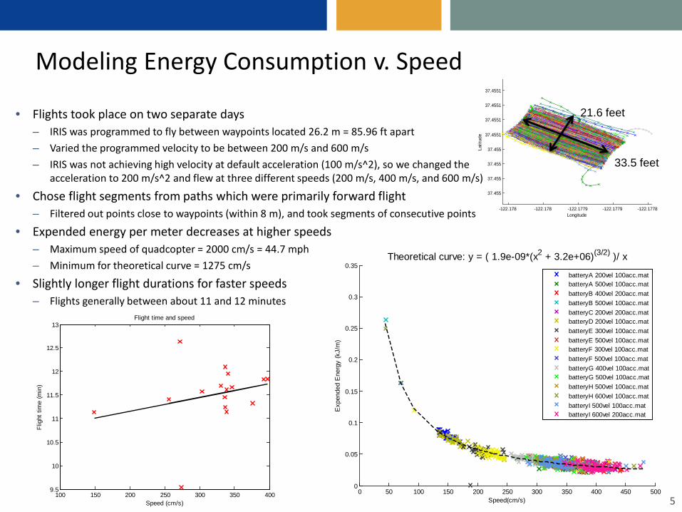
Modeling Energy Consumption v. Speed
• Flights took place on two separate days – IRIS was programmed to fly between waypoints located 26.2 m = 85.96 ft apart– Varied the programmed velocity to be between 200 m/s and 600 m/s– IRIS was not achieving high velocity at default acceleration (100 m/s^2), so we changed the
acceleration to 200 m/s^2 and flew at three different speeds (200 m/s, 400 m/s, and 600 m/s)
• Chose flight segments from paths which were primarily forward flight– Filtered out points close to waypoints (within 8 m), and took segments of consecutive points
• Expended energy per meter decreases at higher speeds– Maximum speed of quadcopter = 2000 cm/s = 44.7 mph– Minimum for theoretical curve = 1275 cm/s
• Slightly longer flight durations for faster speeds– Flights generally between about 11 and 12 minutes
5100 150 200 250 300 350 400
9.5
10
10.5
11
11.5
12
12.5
13
Speed (cm/s)
Flig
ht ti
me
(min
)
Flight time and speed
-122.178 -122.178 -122.1779 -122.1779 -122.1778
37.455
37.455
37.455
37.455
37.4551
37.4551
37.4551
37.4551
Longitude
Latit
ude
21.6 feet
33.5 feet
0 50 100 150 200 250 300 350 400 450 5000
0.05
0.1
0.15
0.2
0.25
0.3
0.35
Speed(cm/s)
Exp
ende
d E
nerg
y (k
J/m
)
Theoretical curve: y = ( 1.9e-09*(x2 + 3.2e+06)(3/2) )/ x
batteryA 200vel 100acc.matbatteryA 500vel 100acc.matbatteryB 400vel 200acc.matbatteryB 500vel 100acc.matbatteryC 200vel 200acc.matbatteryD 200vel 100acc.matbatteryE 300vel 100acc.matbatteryE 500vel 100acc.matbatteryF 300vel 100acc.matbatteryF 500vel 100acc.matbatteryG 400vel 100acc.matbatteryG 500vel 100acc.matbatteryH 500vel 100acc.matbatteryH 600vel 100acc.matbatteryI 500vel 100acc.matbatteryI 600vel 200acc.mat

• Flight tests:– Varying payloads: 0g to 384g– Maximum payload is 400 g– Quadcopter had some difficulty balancing payload in the high
winds– Wind speeds and direction recorded
• Power/Energy consumption increased for higher payloads• Relationship between flight duration and payload
– Flight times are shorter with heavier payloads– Flight durations between 8 and 12 minutes
6
1.25 1.3 1.35 1.4 1.45 1.5 1.55 1.6 1.658
8.5
9
9.5
10
10.5
11
11.5
12
Weight (kg)
Flig
ht ti
me
(min
)
Flight time diminishes with higher payloads
0 200 400 600 800 1000 1200 14000
0.05
0.1
0.15
0.2
0.25
0.3
0.35
0.4
Time (sec)
Powe
r (kW
)
Power
BatteryA part1 100g.tlog.matBatteryA part2 100g.tlog.matBatteryB 50g.tlog.matBatteryC 150g.tlog.matBatteryD 20g.tlog.matBatteryE 200g.tlog.matBatteryF 250g.tlog.matBatteryG 300g.tlog.matBatteryH part1 350g.tlog.matBatteryH part2 mount.tlog.matBatteryI no weight.tlog.mat
Battery H (yellow) had a load of 350g and a high power rate
Battery I (gray) had no payload and a low power rate
1.3 1.4 1.5 1.6 1.7130
140
150
160
170
180
190
200
Payload (kg)
Mea
n po
wer
(W)
Power comparison for different payloads
Payload
Modeling Energy Consumption v. Payload

Acoustic Signal Detection Experiments
Detecting acoustic signals through motor noise at selected altitudes• Platform: 3D Robotics IRIS Quadcopter• Audio collection system
• 3D Printed mounting hardware• Audio Technica ATR6550 Condenser Shotgun Mic ($65)• Tascam DR-05 Portable Digital Recorder v. 2 ($100)
• Backend processing algorithms have proposed alternative mount designs for the microphone.
• These audio tests have been proposed using a fixed wing’s glide to minimize engine noise during collect.
7
Signal Source
Detector
Interference
Battery Current
Relative Altitude

LIDAR Simultaneous Localization And Mapping (SLAM)
• Platform: 3DR IRIS Quadcopter• COTS LIDAR Unit: Slamtec RPLIDAR ($200)
– 2kS/s– Omnidirectional– Angular resolution: 1°
– Range: 6m
• Controller/Data Storage: Raspberry Pi/Arduino ($30)• Custom 3D Printed Electronics mount• Wireless copter telemetry (915MHz)• Flight control (2.4GHz)• VPN/Wi-Fi sensor control (2.4GHz)• Post Process w/ MATLAB
8
LIDAR Sensor Data:

Open Source Hardware & Software
9
• Open Autopilots– Paparazzi UAV– ArduPilot– 3DR Pixhawk– OpenPilot– Many others
• Benefits of Open Hardware– Minimal development cost– Customization– Feature rich– Large community following
• Open Software– Paparazzi GCS– QGroundControl– MissionPlanner– Tau Labs Ground Control– OpenPilot GCS– Many Others

The Super Simple UAV Design (Quadrotor Example)
10
Flight Time
Thrust/LiftBattery
Payloadkilograms
amp hours grams/watt
Generally want 2:1 thrust-to-weight ratio(at 100% throttle combined propeller thrust is capable of lifting 2x the weight of the craft).
Determine the amount of power the motors need to generate that thrust and the demand on the battery
Increasing battery capacity has negative impact of thrust/lift which reduces available payload capacity

Challenges & Limitations
• Navigation in Arctic is not trivial– Rough Weather – Drifting sea ice– Poor maps/charts– Ionospheric effects on satellite signals -> Degraded GNSS Performances– Geostationary satellites are visible at very low elevation angles -> Poor SBAS signal
reception, WAAS not practical– Lower accuracy of magnetic compasses unreliable above N70°
– Lower accuracy of gyro compasses unreliable above N85°
11
• Electronics in Cold/Wet Environments– Some ICs not rated to -40C -> Stick to
Military/Industrial temperature ratings– Lithium-Polymer battery degrades with
temperature

Other Interesting UAV Studies at SRI
• Plan to modify larger fixed wing aircraft and octocopter for existing SRI developed payloads
• Testing and developing sensors– CubeSat testing possibilities– LIDAR sensor ready for additional tests– River speed measurements based on surface current– Miniaturized SAR systems for FOLPEN and GMTI detection– White paper/proposal work
12

Headquarters: Silicon ValleySRI International333 Ravenswood AvenueMenlo Park, CA 94025-3493650.859.2000
Washington, D.C. SRI International1100 Wilson Blvd., Suite 2800Arlington, VA 22209-3915703.524.2053
Princeton, New JerseySRI International Sarnoff201 Washington RoadPrinceton, NJ 08540609.734.2553
Additional U.S. and international locations
www.sri.com
Questions?Thank You!