s.s. cape girardeau - voa.marad.dot.gov 18... · protection) system has been installed on every...
TRANSCRIPT

V E S S E L I N F O R M A T I O N
PCS/RRF - AS SHIP MANAGER FOR DOT/MARAD
PAGE # 1 OF 86
S.S. CAPE GIRARDEAU
EX S.S. PRESIDENT ADAMS
EX S.S. ALASKA MAIL
MARAD DESIGN C5-S-75A MARAD HULL NUMBER 215
NEWPORT NEWS SHIPBUILDING AND DRYDOCK BUILT 10/28/68
OFFICIAL NUMBER 517120
L.O.A. 605'-00"
BREADTH 82'-00"
DEPTH 46'-00"
ENGINES STM. TURB.
SHP 24,000
FUEL CAP 3,668 TONS
DWT 22,216
GROSS 15,949
NET 10,002
V E S S E L I N F O R M A T I O N
PCS/RRF - AS SHIP MANAGER FOR DOT/MARAD
PAGE # 2 OF 86
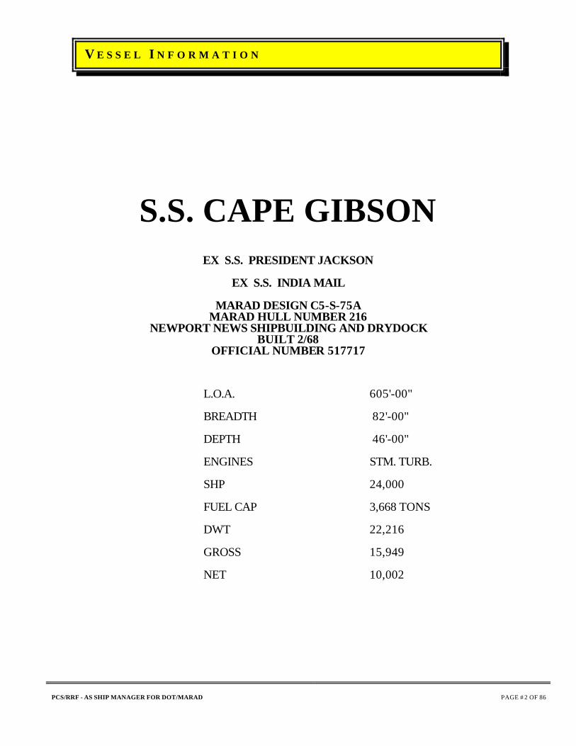
S.S. CAPE GIBSON
EX S.S. PRESIDENT JACKSON
EX S.S. INDIA MAIL
MARAD DESIGN C5-S-75A MARAD HULL NUMBER 216
NEWPORT NEWS SHIPBUILDING AND DRYDOCK BUILT 2/68
OFFICIAL NUMBER 517717
L.O.A. 605'-00"
BREADTH 82'-00"
DEPTH 46'-00"
ENGINES STM. TURB.
SHP 24,000
FUEL CAP 3,668 TONS
DWT 22,216
GROSS 15,949
NET 10,002

LAY-UP SPECIFICATIO N CAPE GIRARDEAU/CAPE GIBSON DTMA-8C-00027
HULL PROTECTION AND D/H PROCEDURES
PCS/RRF - AS SHIP MANAGER FOR DOT/MARAD
PAGE # 3 OF 86
To preserve the hull and protect it from harmful natural predators, A CAPAC (Cathodic Protection) system has been installed on every MARAD vessel. This system is monitored regularly by the Ship Manager's Port Engineer. The only time the CAPAC system is not operable is in the event the vessel is dry-docked and a complete bottom painting is performed. As per recommended manufacturers' warranties, The CAPAC system will not be operable because the new paint must cure properly and the CAPAC system might negate the curing process. To effect an efficient deactivation of its Ready Reserve vessel(s), The Ship Manager will follow the following prepared MARAD "Standard Lay-Up Procedures" and dehumidification guidelines established by the United States Coast Guard and American Bureau of Shipping.
BOILER INSPECTIONS
BOILERS, MAIN STEAM SYSTEMS, AND STEAM SIDES OF TURBINES AND CONDENSERS
SHIP'S SERVICE TURBO-GENERATORS (SSTG'S)
DISTILLERS AND EVAPORATORS
STEAM VESSEL CONTROL SYSTEMS
TURBINE STEAM ADMISSION VALVES
STEAM VESSEL LUBE OIL SYSTEMS
STEAM VESSEL FUEL OIL SYSTEMS
PIPING SYSTEMS
MEDIUM SPEED PROPULSION DIESELS
CARGO WINCHES AND HYDRAULICS
ELECTRONIC GEAR
SAFETY EQUIPMENT
RRF DEACTIVATION PROCEDURES

LAY-UP SPECIFICATION CAPE GIRARDEAU/CAPE GIBSON DTMA-8C-00027
INTRODUCTION
PCS/RRF - AS SHIP MANAGER FOR DOT/MARAD
PAGE # 4 OF 86
The Cape Girardeau and Cape Gibson Specification has been designed to prepare the vessel(s) for lay-up. This specification is divided into two parts: "Part A" with standard lay-up procedures and "Part B" devoted to the repair of known noted deficiencies discovered during either an Activation or Operation. The Ship Manager will package this completed specification (One per vessel) and solicit bids to repair contractors to perform the necessary work and repairs. After completion of the lay-up specification repairs, the vessel will return to its outporting berth.. After Phase V-"Lay-up" the vessels will be placed in Phase IV "Maintenance" status by the Ship Manager; Patriot Contract Services, LLC. GENERAL INFORMATION Contractor shall furnish all labor, material, equipment, and transportation to accomplish repairs, tests, activation and deactivation outlined in this Specification. All work is to be diligently carried out under competent supervision, and completed in an expeditious manner. Contractor-furnished materials and equipment used for repairs to, or replacement of, existing shipboard materials or equipment must comply with all applicable American Bureau of Shipping/U.S. Coast Guard (ABS/USCG) requirements. All repairs and/or renewals are to be completed to the satisfaction of Contracting Officer's Technical Representative (COTR) and representatives of the regulatory bodies. Contractor shall give COTR timely, written prior notice of anticipated inspections for efficient coordination of same. Contractor shall apply a hose test, head test, or pressure test to prove all work accomplished, tight, and otherwise satisfactory to all concerned parties. All removals and replacements required to gain access shall be accomplished, as necessary, in order to effect the repairs, renewals, and additions enumerated herein. All new and/or disturbed equipment, gaskets, joints, etc., covered by these Specifications are to be checked and hardened up before being covered or lagged.

LAY-UP SPECIFICATION CAPE GIRARDEAU/CAPE GIBSON DTMA-8C-00027
PREFACE TO SPECIFICATION
GENERAL INFORMATION - Continued
PCS/RRF - AS SHIP MANAGER FOR DOT/MARAD
PAGE # 5 OF 86
Unless otherwise specified, all steel renewals and/or repairs, and disturbed areas adjacent thereto, at completion of repairs will be blasted and/or wire brushed, or mechanically cleaned and coated with compatible prime and finish-coating system built up to millage level of surrounding area. Unless specifically approved by the COTR the Contractor shall not use any of the ship's spare parts, material, tools, or equipment for repairs or replacements in the performance of the repairs described in these Specifications. If the COTR agrees to the use of vessel spare parts for expediency, Contractor will place an order to replace the parts via a signed purchase order. Access to vessel will be required by other Contractors designated by the COTR. Where specific equipment or materials are identified in the Specifications, equivalent products may be substituted in accordance with the provisions of the Contract after approval by the COTR. Any dimensions for work involved in these Specifications are given for the guidance of the Contractor who is, however, responsible for taking his own measurements. NOTE: Quantities, sizes, locations and description of equipment, appurtenances, and fixtures indicated in these Specifications are given as guidance and are not limited to the amounts as shown. Therefore, all interested companies wishing to be considered for this Contract must, by arrangement before repairs, inspect the ships and make a fair assessment of the labor force required to meet the repair schedule. The vessel's mooring lines shall not be used for towing purposes, or mooring at Contractor's facility. Collect, palletize, and stow all mooring lines in a location as designated by the COTR. Upon completion of contract reinstall mooring lines for use. Contractor shall prepare working drawings or sketches necessary for performance of the work and submit the documents to the COTR for review before submittal to the Regulatory Body and Classification Society for approval. All new, disturbed, or soiled surfaces affected by the work shall be properly cleaned and/or lagged. Tanks, cargo holds, and other spaces affected shall be left clean and ready to receive cargo.

LAY-UP SPECIFICATION CAPE GIRARDEAU/CAPE GIBSON DTMA-8C-00027
PREFACE TO SPECIFICATION
GENERAL INFORMATION - Continued
PCS/RRF - AS SHIP MANAGER FOR DOT/MARAD
PAGE # 6 OF 86
No debris shall be allowed to accumulate on the vessel during repairs. Trash shall be removed daily, and decks left in a clean and safe condition. Remove bilge water daily or more frequently as needed. Upon completion of all repairs and removal of all Contractor equipment, the COTR and a representative of the Contractor are to inspect all areas of the vessel to ensure that the vessel is clean (free of trash, dust, sand, grease, debris, or residue), dry, and ready for lay-up. Any cleaning required to achieve this standard will be accomplished before the vessel leaves the Contractor's facility. All insulation of the vessel shall be considered asbestos-based. If it is necessary to disturb any insulation during repairs, Contractor shall furnish qualified/certified facility and chemist to ascertain and define the material through laboratory analysis. If laboratory analysis is positive, Contractor shall furnish a qualified/certified facility for containment and disposal of material according to OSHA Regulations, Volume One, Article 1910.1001 and/or MIL/STD-769F. Contractor shall supply staging and/or scaffolding required to complete any Items, including erection and dismantling of same. Contractor shall maintain good housekeeping affecting all Contract Items, i.e., all parts removed in way of machinery, equipment, and structural components shall be put aside in an orderly manner, in proper and safe locations and/or containers, and identified by tagging for correct, speedy reuse and reinstallation. Proper care is to be exercised to protect all exposed machinery, equipment, and structural parts of vessel covered under repair Items which might be subject to weather and/or mechanical damage. If Contractor intends to use an equally qualified service technician in lieu of the manufacturer representative, Contractor must present sufficient evidence to the COTR proving that the intended Subcontractor is capable of satisfactorily completing the Item(s). The COTR will approve or disapprove the intended Subcontractor at that time. Contractor shall not allow employees, Subcontractor, or others to manufacture gaskets as required in various Items in this Specification by using the ball-peen-hammer method. All gaskets are to be cut by using proper gasket-forming tools, such as arch punches.
LAY-UP SPECIFICATION CAPE GIRARDEAU/CAPE GIBSON DTMA-8C-00027
PREFACE TO SPECIFICATION
GENERAL INFORMATION - Continued
PCS/RRF - AS SHIP MANAGER FOR DOT/MARAD
PAGE # 7 OF 86
Contractor shall furnish a competent and qualified person(s) capable of operating marine equipment for any tasks and/or operational inspection required to successfully complete Items in this Specification. Electrical power, air, and firemain water to be made available immediately upon vessel's arrival at Contractor's wharf. All work to be in accordance with applicable Federal, State and Local Environmental Regulations. Contractor and Sub-Contractors to initiate all required Hazardous Material and Waste reports, manifests, etc. and insure they are completed with file copies provided to COTR.
MEETINGS
An arrival conference shall be held between Contractor's senior staff and the COTR at a time and place mutually agreeable to all parties at or just prior to vessel's arrival at the Contractor's facility. An initial Production Control meeting shall be held between Contractor, Craft Foremen, and the COTR on the day of the Notice To Proceed at a time and place mutually agreeable to all parties. Weekly progress meetings shall be held between Contractor's Project Manager, Craft Foremen, and the COTR at a time and place mutually agreeable to all parties.

LAY-UP SPECIFICATION CAPE GIRARDEAU/CAPE GIBSON DTMA-91-93-C-00069
PREFACE TO SPECIFICATION
PRODUCTION CONTROL
PCS/RRF - AS SHIP MANAGER FOR DOT/MARAD
PAGE # 8 OF 86
GENERAL:
The Contractor shall thoroughly plan and schedule all items of this specification including an estimated allowance for time to do repairs on all open and inspected items. (Total hours planned shall not exceed supplemental CLIN hours allowed for by Contract.) Reports of production, manpower and material shall be diligently provided to the COTR as required herein. DEFINITIONS:
ACTIVITY A portion of an individual work item which is a logical subdivision of the work item representing a manageable unit of work which must be accomplished at a specific period of time in relation to other activities of the contract work. CONTROLLING WORK ITEMS Those work items which are on the critical path of the Contract and those work items which by virtue of scope, material requirements, complexity, or other considerations have the potential for impact on the scheduled completion of the contract period. CRITICAL PATH That work item or a combination of work items which forms the longest duration, and directly affects the completion of the contract. Factors in determining critical path are: time duration required for the work item, space limitations, manpower available, and the interface between work items. EVENT The beginning or ending point of an activity. FLOAT The amount of time an event can be delayed without delaying the start of the subsequent or follow-on activities. KEY EVENT An event which cannot slip without impacting or delaying the overall schedule. Key events may be identified by either the owner's representative or the contractor. MILESTONE A significant event mutually identified at the Arrival Conference that is invoked within the specifications.

LAY-UP SPECIFICATION CAPE GIRARDEAU/CAPE GIBSON DTMA-91-93-C-00069
PREFACE TO SPECIFICATION
PRODUCTION CONTROL
PCS/RRF - AS SHIP MANAGER FOR DOT/MARAD
PAGE # 9 OF 86
DEFINITIONS: - Continued
NETWORK (PERT CHART) A graphic display showing the relationship of work items, milestones, key events, and activities within the Contract. PRODUCTION SCHEDULE (GANTT CHART) The schedule used by the contractor and subcontractor personnel as a means of planning, tracking, and coordinating the accomplishment of contract work. PRODUCTION SCHEDULE:
On the day of the Initial Production Control meeting, Contractor shall deliver to the COTR a Production Schedule Gantt Chart with three (3) copies, showing each work item of the Contract, including all subcontracted work and milestones. Each item shall clearly depict each major phase such as engineering, fabrication, installation, testing, and coatings, etc. Each phase shall have a planned start and stop date. Float days shall be shown next to each phase to indicate the total amount of days this particular phase may slip without any overall impact to the delivery date of the vessel. The Gantt Chart shall have the appropriate columns to indicate Item Number, Item Description, Estimated Duration of days needed to Complete the Item, Start Date, Finish Date, Float Days and percentage Weight of the Total Contract for each Item. All items (or any phase of an item) for which the Contractor allows zero float days shall be defined as a "critical item". All events associated with "critical items" are "key events". Activity titles shall be in bold, black print. All Controlling Items, Critical Items and Key Events shall be shown in extra heavy bold letters or equal distinguishing marks. Additionally, the Gantt Chart shall depict:
The latest allowable receipt date for Contractor and government furnished material to maintain the original production schedule. Scheduled key events/milestones. Scheduled dates of tests. These tests are to include hydrostatic, operational, weight tests, safety devices, etc. All tests are to be coordinated through the COTR one day prior to execution. This notification is to be in addition to the requirements of the contractor's Quality Assurance Plan guidelines.

LAY-UP SPECIFICATION CAPE GIRARDEAU/CAPE GIBSON DTMA-91-93-C-00069
PREFACE TO SPECIFICATION
PRODUCTION CONTROL
PCS/RRF - AS SHIP MANAGER FOR DOT/MARAD
PAGE # 10 OF 86
PRODUCTION SCHEDULE - Continued
A complete list of all Contractor prepared drawings with preliminary and final drawing delivery dates identified. Contractor is to prepare a time critical network Pert Chart that displays the relationship of key events, milestones, critical path work items, and controlling work items. Contractor to submit three (3) legible copies of the network (Pert Chart) to the COTR one working day prior to the first contract progress meeting, identified elsewhere in this work item. Contractor to revise the production schedule (Gantt Chart) mentioned above and the network (Pert Chart) weekly (one day prior to progress meeting) to reflect the addition, deletion, or modification of work items, and changes made by the contractor. Copies to be submitted as detail above. PROGRESS REPORTING
Weekly progress meeting participants shall be prepared to address critical path, controlling work and offer reasonable solutions to problems which may have impact on scheduled milestones or completion date. Interface between Contractor scheduled and planned ship crew requirements to support the Contractor testing and equipment operation schedule. Provide cognizant management representation to participate in the weekly progress meeting. The representative must be authorized to make management decisions relative to routine requirements of the Job Order which, in good faith, commit the contractor. One day prior to the weekly progress meeting submit three (3) legible copies of a production status report to COTR. The production status report is to include an updated production schedule. The following is to be submitted for each work item: Percentage completion. Late contractor furnished material. Late government furnished material. Late or deficient government furnished information. A report of overdue contractor condition reports listing work item number and expected submission date. The report shall also include those deficiency and condition reports for which government response is outstanding. Action taken or proposed to resolve problems which have been presented themselves as potential impact on the contract milestones and/or completion date.

LAY-UP SPECIFICATION CAPE GIRARDEAU/CAPE GIBSON DTMA-91-93-C-00069
PREFACE TO SPECIFICATION
PRODUCTION CONTROL
PCS/RRF - AS SHIP MANAGER FOR DOT/MARAD
PAGE # 11 OF 86
PROGRESS REPORTING - Continued
A report listing Contractor and Government furnished material not received, showing the work item number and title, material description, expected delivery date, required delivery date, and action proposed to resolve problems resulting from late delivery. Any items which may impact the schedule for completing this Specification shall be identified to the Government as soon as possible, but not later than 24 hours after being identified. The COTR shall be the final authority in the determination of percentage of progress of each work item and determination of overall progress percentage (completion percentage) by the Contractor and Subcontractors. MANNING AND SUBCONTRACTORS:
At the Initial Production Control meeting, Contractor shall deliver to the COTR a Scheduled Man-hour Report with a breakdown of each item listed in the Contract Specifications. The breakdown for each item shall show total man-hours scheduled for each item each week by craft. Contractor to revise the Scheduled Man-hour Report mentioned above weekly (one day prior to the weekly progress meeting) to reflect the addition, deletion, or modification of work items, and changes. Three (3) copies to be delivered to the COTR. One day prior to the weekly progress meeting, submit three (3) legible copies of a report documenting the manpower actually utilized during the previous production period. The report is to be broken down by trade and Sub-Contractor for man-hours expended and
LAY-UP SPECIFICATION CAPE GIRARDEAU/CAPE GIBSON DTMA-91-93-C-00069
PREFACE TO SPECIFICATION
SERVICES
PCS/RRF - AS SHIP MANAGER FOR DOT/MARAD
PAGE # 12 OF 86
MANNING AND SUBCONTRACTORS: Continued
include a composite graphic depiction of total labor utilization for the entire production period. Manage and schedule subcontractor's performance with respect to work progress, material procurement, and interface control to support the production schedule. Submit to the COTR three (3) legible copies of a complete list of subcontractors by work item at the same time the production schedule is submitted. The subcontractor list shall include:
Work item paragraph number. Specific work to be accomplished. Sub-Contractor's business address.
Submit three (3) legible copies of a report to the COTR of changes to the original list prior to making changes in Sub-Contractor responsibilities. MATERIAL CONTROL SCHEDULE:
At the Initial Production Control meeting, the Contractor shall submit a "Material Control Schedule". The Material Control Schedule shall list all major material purchases by specification number, quantity required, source (supplier), proposed delivery date, any potentially long lead time deliveries which may affect successful completion of item, and will show responsibility for procurement by Contractor or Sub-Contractor. The Contractor shall immediately notify the COTR of any changes to the Material Control Schedule. The Contractor shall provide the COTR with a Material Receiving Report for all material and equipment delivered to the Contractor which will be used on this Contract. Material Receiving reports shall be delivered to the COTR weekly at the Progress Meeting.

LAY-UP SPECIFICATION CAPE GIRARDEAU/CAPE GIBSON DTMA-91-93-C-00069
PREFACE TO SPECIFICATION
SERVICES
PCS/RRF - AS SHIP MANAGER FOR DOT/MARAD
PAGE # 13 OF 86
PATRIOT CONTRACT SERVICES, LLC (PCS), INSPECTION
When specification items require that an PATRIOT CONTRACT SERVICES, LLC (PCS) Representative, identified as COTR, accept and witness in-progress work, completed work, testing, or inspections, Contractor shall provide written notification to the COTR at least twenty-four (24) hours in advance of the work sequence to be witnessed or approved. When work to be witnessed or approved is to occur after normal day-shift working hours or on a weekend, PATRIOT CONTRACT SERVICES, LLC (PCS), COTR shall be notified at least four (4) hours before the end of the regular work shift one day prior to the inspection. The PATRIOT CONTRACT SERVICES, LLC (PCS) COTR may designate work sequences, in addition to those identified by the Specification Item, to be observed or inspected by a PATRIOT CONTRACT SERVICES, LLC (PCS) Representative or regulatory body. The aforementioned notification requirements shall also apply to these designated work sequences. PATRIOT CONTRACT SERVICES, LLC (PCS) inspection is an independent function of the Owner and does not relieve Contractor of responsibility to perform tests and inspections required by the Specification or those considered necessary to ensure product conformity. REGULATORY BODY INSPECTIONS AND SURVEYS
All equipment addressed and applicable to ABS Special Survey shall be presented to the ABS Surveyor for approval. All tests on tanks, machinery and miscellaneous equipment shall be presented to ABS and USCG for approval. All tests and inspections for a C.O.I. from the USCG shall be addressed and presented to the USCG for approval. SUPERVISION
All work items on main engine, throttle valves, generators and gears shall be supervised by an owner furnished technical representative.

LAY-UP SPECIFICATION CAPE GIRARDEAU/CAPE GIBSON DTMA-91-93-C-00069
PREFACE TO SPECIFICATION
SERVICES
PCS/RRF - AS SHIP MANAGER FOR DOT/MARAD
PAGE # 14 OF 86
ADMINISTRATIVE SERVICES
Contractor shall provide the COTR with following administrative services from NOTICE TO PROCEED until acceptance. OFFICES At Contractor's facility, Contractor shall provide suitable office space within 100 yards of the ship, with work areas for the COTR (400 sq-ft minimum), including air conditioning, heating, and sufficient desks, chairs, lockers, and filing cabinets. Two (2) telephones with hold and transfer capability, and one (l) facsimile machine with separate FAX line in the COTR's office with unrestricted local and long distance service. Assume for bidding purposes that $1,200 of long distance billing shall be utilized on these telephones, and the dedicated modem line as noted in section 2a. below. Paper for facsimile machine shall be provided on as needed basis. Toilet and washroom facilities including hot and cold water, shower and towels. The toilet and washroom facility square footage area shall not be included in the 400 square foot minimum office space as referenced above. COMPUTER EQUIPMENT Contractor shall furnish the following computer related equipment:
Two (2) 486-33MHz IBM compatible personal computers with 4 Mb RAM and both 5-1/4" floppy (1.2 Mb) and 3-1/2" floppy (1.4 Mb) disk drives with 80 Mb (minimum) hard drive, SVGA monitor, SVGA graphics card and mouse. One computer to have a 9600/2400 BAUD Hayes-compatible send/receive fax/modem. Fax/modem to have a dedicated phone line separate from lines specified above. One (l) Laser printer (equivalent to an HP LaserJet IIP with a lower cassette), with sufficient paper, connected to both computers using an A-B connector box. The following program software with documentation and manuals, loaded, setup and initialized to run in the "MS windows" environment and with related hardware:
MS-DOS 6.22 MS-WINDOWS
MS-OFFICE PROFESSIONAL:
(WORD 6.0, EXCEL 5.0, ACCESS 2.0)
VISIO
TURBO CADD
LOTUS CC:REMOTE PROCOMM PLUS
Two (2) Uninteruptable power supplies and all associated cables.
LAY-UP SPECIFICATION CAPE GIRARDEAU/CAPE GIBSON DTMA-91-93-C-00069
PREFACE TO SPECIFICATION
SERVICES
PCS/RRF - AS SHIP MANAGER FOR DOT/MARAD
PAGE # 15 OF 86
ADMINISTRATIVE SERVICES - Continued
OFFICE EQUIPMENT One (l) copy machine capable of copying legal size and letter-size paper, with reduction and enlargement modes sufficient letter-size and legal size paper. Copier shall be capable of producing 2 sided copies, and shall have sorting and grouping features. Any and all setup and service shall be included. One (l), four (4) drawer, locking file cabinet with two (2) keys. Three (3) desks with three (3) swivel-roller armchairs and one (1) Secretary chair. One (1) IBM correcting Selectric or equivalent typewriter and stand. One (1) 36" x 60" dry-erase board with sufficient markers suitably mounted on wall. One (1) 36" x 60" cork board with stick pins.

LAY-UP SPECIFICATION CAPE GIRARDEAU/CAPE GIBSON DTMA-91-93-C-00069
PREFACE TO SPECIFICATION
SERVICES
PCS/RRF - AS SHIP MANAGER FOR DOT/MARAD
PAGE # 16 OF 86
VESSEL SERVICES
Contractor shall provide all general services for the vessel while it is in Contractor's facility. For Contractor and Subcontractor personnel, Contractor shall provide necessary/required services, machinery, and equipment for work specified in Items of these Specifications and additional work as directed by the COTR during Contract. Contractor will not be allowed to use any ship equipment unless stated in this Specification or with written approval of the COTR. General services to be provided by Contractor shall include, but are not limited to, the following. BERTH A suitable berth with adequate fendering where ship may lie safely afloat at all times, and ship placed at same upon arrival at Contractor's plant by Contractor personnel for all work specified in Items of these Specifications or additional work found necessary which can be accomplished during ship's Contract availability. Contractor to supply mooring lines; ship's mooring lines are not to be used. GANGWAY A sturdy gangway of adequate length for safe access to/from vessel during Contract period whether vessel is afloat or on dry-dock. Gangway shall have adequate safety railings, safety net, and suitable night lighting. TUGS, PILOTS, LINE HANDLERS Contractor shall provide tugs and pilots for arrivals, departures, and as required to shift the vessel for performance of work during the contract period, and shall provide labor to handle lines and gangway for all moves. SHORE POWER Contractor shall provide heavy-duty shore power cable in good condition, connect and disconnect as necessary, and supply shore power to the vessel (800 amp, 450v, 3 phase, 60 Hz) while the vessel is in Contractor's facility, with phase protection. The A/C electrical power shall be maintained continuously at a maximum of 460v, with minimum 440v at ship's shore power connection.

LAY-UP SPECIFICATION CAPE GIRARDEAU/CAPE GIBSON DTMA-91-93-C-00069
PREFACE TO SPECIFICATION
SERVICES
PCS/RRF - AS SHIP MANAGER FOR DOT/MARAD
PAGE # 17 OF 86
VESSEL SERVICES - Continued
COMPRESSED AIR Contractor shall provide filtered, dry, oil-free, moisture free compressed air (minimum 125 psig, 1500 CFM) and shall connect and disconnect hoses as necessary upon arrival and departure, and for all vessel movements. FIRE PROTECTION Contractor shall have qualified fire watch person(s) and supply portable fire extinguishers at all times in each area/compartment, properly equipped, where burning and/or welding is being done. Contractor shall install a minimum of two (2) fire protection stations (temporary, portable " CHRISTMAS TREE" type) on the main deck and/or at work sites. Each fire station shall have a 400-GPM capacity and 450' of 2-1/2" fire hoses with fire nozzles activated for the entire contract period. Vessel's hoses are not to be used. NOTE: Vessel's firemain system is not to be used after dock trial/ sea trial. CHEMIST CERTIFICATE Contractor shall provide gas-free certificates, "Safe for Men, Safe for Hot Work," updated daily for any areas requiring access, burning, or welding. Certificates shall be issued only by a certified "Marine Chemist" or "Competent Person" as defined by USCG Regulations. Portable fire fighting equipment (CO2 bottles, water cans, and dry chemical extinguishers) shall be provided while burning and welding. Ship's extinguishers shall not be used. VENTILATION Contractor shall provide all portable blowers and ducting for ventilation as necessary for safety of Contractor's and ship's assigned working personnel during the contract period, and as needed for inspection of tanks by Regulatory Inspectors. ELECTRICAL & LIGHTING SERVICE Contractor shall provide electrical source of power for adequate lighting, blowers, hoists, welding machines, etc., for all compartments and spaces as necessary to accomplish work specified herein, and as directed by the COTR. Contractor shall ensure that all compartments and areas being worked have sufficient Contractor-supplied lighting and ventilation at all times. Compartments and areas being worked may have ship-supplied lighting and ventilation; however, some work will require isolation of ship's power systems. Temporary services shall be provided by Contractor as needed. Contractor shall be responsible to survey and prove safe all power source cable before starting any work.

LAY-UP SPECIFICATION CAPE GIRARDEAU/CAPE GIBSON DTMA-91-93-C-00069
PREFACE TO SPECIFICATION
SERVICES
PCS/RRF - AS SHIP MANAGER FOR DOT/MARAD
PAGE # 18 OF 86
VESSEL SERVICES - Continued
ELECTRICIAN SERVICE Contractor shall furnish services of certified, competent electricians with all tools and equipment required to energize necessary electrical circuits as required to test, repair, and/or operate equipment as required at any time. WATCHMEN Contractor shall furnish 24-hour services of bonded, uniformed security guards onboard the vessel in three (3) shifts of eight (8) hours each on weekends and holidays and two (2) shifts of eight hours each, Monday through Friday, covering swing and graveyard shifts, from vessel's arrival at Contractor's facility through complete contract period. The exception to this shall be the period of the vessel sea trial while the vessel is away and no guard service will be required. Guards to be instructed that Contractor's personnel are forbidden access to any part of vessel unnecessary to complete Items, except under emergency conditions such as fire, storm, etc. Security guards are to keep a log book and record conditions found while checking the vessel at hourly intervals (minimum), and all visitors with their respective affiliations and time on and off vessel. AIR-DRIVEN PUMPS/BILGES Contractor to furnish air-driven pumps, hoses, and labor to pump all bilges ashore as required to maintain a dry condition aboard ship. Slops to be properly disposed in accordance with all applicable regulations. STAGING Contractor to furnish and erect staging necessary to access work as specified, and remove upon completion. CRANE SERVICE Contractor to furnish necessary crane service to accomplish work as specified on a timely as needed basis.

LAY-UP SPECIFICATION CAPE GIRARDEAU/CAPE GIBSON DTMA-91-93-C-00069
PREFACE TO SPECIFICATION
SERVICES
PCS/RRF - AS SHIP MANAGER FOR DOT/MARAD
PAGE # 19 OF 86
VESSEL SERVICES - Continued
TELEPHONE Contractor to furnish one (1) telephone in Chief Engineer's office with unlimited local and long-distance calling and one (1) cellular telephone. Assume for bidding purposes that total combined long distance charges shall not exceed $ 1,000 per month, including calls on the telephones and fax supplied under "Administrative Services" in these specifications. Installation and local call fees shall be paid by the Contractor and shall not be included in the above not-to-exceed figure. SHORE STEAM Contractor to furnish necessary 125 PSIG shore steam to vessel to accomplish work as specified on a timely as needed basis. Shore steam shall have a properly sized strainer in line. DEBRIS REMOVAL All debris and trash generated during period of contract to be removed from vessel and properly disposed of daily. POTABLE WATER Contractor to furnish drinking fountain or bottled, refrigerated water cooler aboard vessel in Chief Engineer's Office. Water to be supplied as necessary. PORTABLE TOILETS Contractor to furnish two (2) portable toilets on the vessel. Toilets to be serviced weekly or sooner as required.

LAY-UP SPECIFICATION CAPE GIRARDEAU/CAPE GIBSON DTMA-91-93-C-00069
LAY-UP SPECIFICATION "PART A"
STANDARD DEACTIVATION PROCEDURES
PCS/RRF - AS SHIP MANAGER FOR DOT/MARAD
PAGE # 20 OF 86
VESSEL LIGHTING
Provide qualified electricians and lamps to lamp up all incandescent and fluorescent fixtures. Insure proper wattage lamps are used. This is to be accomplished immediately upon award of contract and maintained throughout contract period. SHAFT & RUDDER LOCK REMOVALS
Shaft Lock
Provide labor, material and equipment to reinstall shaft lock for shift from lay berth to Contractor yard and return shift back to lay berth. If required, upon arrival Contractor yard, remove shaft lock-stow in shaft alley in secure position. Reinstall coupling guard. The thwart ship bracket does not have to be removed unless the tailshaft is to be drawn. Reinstall shaft lock for shift to lay berth. Upon arrival at lay berth, remove shaft lock-stow in shaft alley in secure position. Reinstall coupling guard. Rudder Lock
Provide labor, material and equipment to reinstall flanged split pipe locks on rudder. (There are 4 pieces to make up 2 flanges). Do not mix or you will have trouble reassembling. Upon arrival in Contractors yard, remove flanges, label and secure in a safe position in S/G room. Check out steering system electrically and mechanically. Lubricate and add oil if needed. Perform operational test in presence of chief engineer, owners representative and Regulatory Bodies. At completion of deactivation and prior to shift back to lay berth, reinstall rudder locks.

LAY-UP SPECIFICATION CAPE GIRARDEAU/CAPE GIBSON DTMA-91-93-C-00069
LAY-UP SPECIFICATION "PART A"
STANDARD DEACTIVATION PROCEDURES
PCS/RRF - AS SHIP MANAGER FOR DOT/MARAD
PAGE # 21 OF 86
SHIFTING AND TOWING
Provide necessary tugs, tow preparation, pilots, riding crew and line handlers plus all required equipment and permits to pick up the vessel at Hunter's Point Naval Base, South Pier, San Francisco, California and deliver to Contractors facility as a "Dead Ship". At conclusion of contract, re-deliver the vessel from Contractors facility to lay up berth at Hunter's Point Naval Base, South Pier, California. For all tows to/from Contractor's repair facility, Contractor to provide services of Abstech or independent marine consultant recognized by Contractor's insurance carrier and comply with recommendations for suitability or arrangement for a trip in tow. Provide portable sanitation facilities on the stern of the vessel for use of riding crew during tow. Contractor to install shaft lock and rudder locks prior to each tow. Securing for ocean tow shall be by lashing and shoring. No taping will be allowed. Any alterations to D/H system or weather closures required for tow to be restored to original configuration upon vessels return to lay berth. All vessel moves are for the Contractors Account. All disconnections and re-connections of services to vessel are for the Contractors Account. Riding crew shall be equipped with three (3) portable radio transceivers of same frequency, one at vessel's bow, one at stern, and one with attendant alongside Pilot on bridge.

LAY-UP SPECIFICATION CAPE GIRARDEAU/CAPE GIBSON DTMA-91-93-C-00069
LAY-UP SPECIFICATION "PART A"
STANDARD DEACTIVATION PROCEDURES
PCS/RRF - AS SHIP MANAGER FOR DOT/MARAD
PAGE # 22 OF 86
HULL BLANKS (DRYDOCK)
DRYDOCKING
Furnish labor, equipment and material to set docking blocks under the direct supervision of dock master in accordance with above referenced docking plans formulated for the vessel and dock vessel to perform underwater cleaning, survey, coating and repairs as described in these specifications. Contractor to submit docking plan showing location and size of blocks prior to commencement of work. Vessel to be drydocked as soon as practicable upon commencement of contract. Submit three (3) copies of typewritten drydocking report to Owner's Representative upon completion of work. Upon completion of all examinations and repairs, undock vessel in good order and shift to adequate wet berthage. Any fender which will abrade the paint at the water line or below is not to be used. Vessels gross tonnage to be determined by contractor. SEA CHESTS
Furnish labor, material as required and equipment to erect and remove staging to unfasten and remove strainer plates and splitter bars from a total of six (6) sea chests. Thoroughly wash and flush with fresh water all interior surfaces of sea chests, and overboard discharges including strainer plates. Prove all foreign material removed to satisfaction of COTR. Coat interiors of sea chests, including both side of strainers with same schedule as bottom paint Upon satisfactory draining and drying of all machinery systems and piping and when directed by COTR replace strainers as original, renewing stainless steel wire lacing and replacing any missing or defective studs, nuts, bolts or keepers with stainless steel.
THE FOLLOWING IS A LIST OF SEACHESTS: Main Circ High suct. Frs 114-118 stbd Main Circ Low suct. Frs 119-121 stbd Aux Circ Low suct. Frs 120-121 stbd Bilge & ballast pumps suct. Frs 130-131 port Fire & sanitary pumps suct. Frs 132-133 port Shaft alley fire pump suct. Frs 194-195 stbd
LAY-UP SPECIFICATION CAPE GIRARDEAU/CAPE GIBSON DTMA-91-93-C-00069
LAY-UP SPECIFICATION "PART A"
STANDARD DEACTIVATION PROCEDURES
PCS/RRF - AS SHIP MANAGER FOR DOT/MARAD
PAGE # 23 OF 86
HULL BLANKS (DRYDOCK)
HULL BLANKS
PREPARATION AND COATING OF HULL BLANKS Sandblast the seventeen (17) hull blanks stowed in #1 Cargo Hold, Main Deck, P/S to near-white metal (SSPC SP-lO), repair any damaged stPCSes. Contractor is to weigh each blank and insure that weight matches weight of blank as identified on each blank. If weight does not match contractor is to grind off weight I.D. welded on each blank and reweld the correct weight I.D. on blanks. Check and correct if necessary blank numbering against listing below, make required changes if any by grinding off improper blank numbers and reweld new number. Provide owners rep/COTR with report listing blanks by frame location, service overboard or sea suction installed on, size, weight, and identification number. Apply two (2) full coats of Marad approved surface-tolerant, high solids epoxy at 4-5 mils DFT each, in accordance with all Manufacturer's approved guidelines and procedures to both sides of blanks. Allow a minimum of six (6) hours drying time at 77 degrees F before over-coating each coat; increase over-coating time at lower temperature. After blanks have been installed and tested, touch up any disturbed or damaged areas the above coating. Apply three (3) full coats of Marad approved Ablative or self polishing copolymer anti-foulant at 4-5 mils DFT each, in accordance with all Manufacturer's approved guidelines and procedures to exposed exteriors of blanks. Allow a minimum of six (6) hours drying time at 77 degrees F before over-coating each coat; increase over-coating time at lower temperatures.

LAY-UP SPECIFICATION CAPE GIRARDEAU/CAPE GIBSON DTMA-91-93-C-00069
LAY-UP SPECIFICATION "PART A"
STANDARD DEACTIVATION PROCEDURES
PCS/RRF - AS SHIP MANAGER FOR DOT/MARAD
PAGE # 24 OF 86
HULL BLANKS (DRYDOCK)
HULL BLANKS
BLANK LOCATION AND SIZE
Side Function Weight Size Frame Stbd Main Cond. High Suction x 67" Port Main Condenser Overboard OD Stbd Main Cond. Low Suction x 128" Port Service Overboard OD Stbd Aux. Cond. Overboard OD Port Suction x 63" Stbd Aux. Cond. Sea Suction x 32" Port Evaporator Brine Overboard OD Stbd Service Trunk Suction x 35" Port Bilge, Ball. & Fire Overboard OD Stbd Aux. Cond. Overboard OD Port Contam. Evap Bottom Blow 3/4" OD Stbd Main L.O. Cooler Overboard OD Stbd Boiler Bottom Blow Overboard 3/4" OD Stdb Sewage Overboard OD Stbd Bilge Overboard OD Stbd Fire Pump Suction 1/2" x 27"
LAY-UP SPECIFICATION CAPE GIRARDEAU/CAPE GIBSON DTMA-91-93-C-00069
LAY-UP SPECIFICATION "PART A"
STANDARD DEACTIVATION PROCEDURES
PCS/RRF - AS SHIP MANAGER FOR DOT/MARAD
PAGE # 25 OF 86
HULL BLANKS (DRYDOCK)
HULL BLANKS
INSTALLATION When all draining and drying of all machinery systems and piping has been completed and when directed by COTR, install all sea chest steel blanks with live rubber sheet packing having minimum thickness of 3/16", using stainless steel cap bolts of #304 stainless steel 3/4" diameter with full threads. Bolts shall be installed with 3/4" stainless steel washers. The stainless steel washer shall be used with a teflon washer or cotton wicking and silicon under the washer. Each washer shall be no less than 1/8" thick. Bolt lengths shall be sized to extend approx. 3/4" into threaded holes of the bolting ring when the gasket is compressed to form the watertight/airtight joint. TESTING Provide and remove required staging. Close sea valves associated with each blank, hook up air line with pressure regulator and gauge to blanks and prove all blanks tight to satisfaction of COTR using 3 psig and soap test from dock. Upon completion, reinstall plugs in blanks.
PERMANENT TAG LINES The Contractor shall furnish and install stainless steel vinyl coated 3/16" cable as tag line on each blank. One end of the cable to be attached to a stPCSe located on cap rail directly above the blank location on the hull, the other end of the cable attached to the stPCSe on the blank. Attachments securing the cable ends to the stPCSes shall be stainless steel. An easily legible tag of a non-deteriorating material shall be placed on the stPCSe on the cap rail identifying the blank with the information from contractor generated list as outlined above.

LAY-UP SPECIFICATION CAPE GIRARDEAU/CAPE GIBSON DTMA-91-93-C-00069
LAY-UP SPECIFICATION "PART A"
STANDARD DEACTIVATION PROCEDURES
PCS/RRF - AS SHIP MANAGER FOR DOT/MARAD
PAGE # 26 OF 86
ENGINEROOM CLEANING
Furnish necessary labor, material, and equipment to clean entire engineroom, machinery space/shaft alley upon completion of all work in machinery space. Vacuum and clean all traces of soot and dust from machinery, pipe lines, and crevices. Soogie all bulkheads, machinery, pipe lines, over heads, foundations, etc. from upper fidley to lower engineroom/shaft alley. Soogieing is to be with a water/biodegradable degreaser mixture. Contractor is to provide and employ sponges, rags and turks head brushes for soogieing all engine/machinery space and equipment to remove all grease and dirt build up followed by a fresh water rinse. Contractor is to protect all electrical equipment during cleaning of engine room. Contractor to remove all cleaning slops and dispose in accordance with all local, state and Federal Regulations. Sweep all floor plates, remove all trash and debris ashore, and dispose of same. Wash down and pump bilges clean as required, ensuring that all loose paint chipping, dirt, etc., is removed and disposed of in accordance with all local, state and Federal Regulations. BOILER FIRESIDE CLEANING Contractor shall thoroughly clean the interior and firesides of both boilers including furnace tubes, vestibules, economizers, uptakes, cavities, duct work, air heaters, double air casings, and windboxes with a high-power industrial vacuum cleaner and compressed air. Contractor shall clean all burners and atomizer tips (including spares). Check atomizer tips to determine serviceability in accordance with manufacturer's tolerances. Inventory burners and atomizers to determine if there is a sufficient number of each size for operation. Coat burners with preservative and stow in racks or another safe location. Coat sprayer plates and other loose parts with preservative, place in heat-sealed polyethylene bags with labels inside bags and stow in a sealed container in a stowage location designated by COTR. Record location of all stowed equipment. Four (4) copies shall be delivered to COTR, and one (l) copy shall be placed in the files in the Chief Engineer's office. Contractor shall clean and inspect all burner registers. Parts damaged during operational testing and dock trials are to be replaced. Free up and thoroughly lubricate. Renew all gaskets and reinstall all registers except those to be replaced with fans. Block uninstalled registers off the deck. Provide new gaskets in heat-sealed polyethylene bags, with labels and placed in storage container as directed by COTR ready for installation.
LAY-UP SPECIFICATION CAPE GIRARDEAU/CAPE GIBSON DTMA-91-93-C-00069
LAY-UP SPECIFICATION "PART A"
STANDARD DEACTIVATION PROCEDURES
PCS/RRF - AS SHIP MANAGER FOR DOT/MARAD
PAGE # 27 OF 86
BOILER LAY-UP
Following completion of satisfactory dock trial and when boilers have cooled, Contractor shall drain each boiler and thoroughly dry each boiler's watersides and firesides by wiping down and using hot, dry, compressed air to blow any standing water from each boiler's watersides. The use of hot, dry, compressed air is necessary to ensure moisture is removed from pockets and tubes where moisture may collect or remain due to vessel's trim. A fiber optic bore scope equipped with a 25X lens and remote video screen to be used to verify complete drying of boiler in presence of COTR. Remove all handhole plugs/manhole plates from superheater headers, waterwall headers, economizer headers, steam and mud drums clean same to remove all rust/scale. Clean seats and handhole plugs of headers. Inspect all seating areas for steam cutting. Replacement of handhold plates will be outlined in Boiler Retention Phase Preservation Systems Item. Furnish new inconel gaskets for handholes plus 15% extra for use during activation phase. Gaskets to be heat-sealed in polyethylene bags with clearly visible labels detailing contents placed inside of bags. Bags to be placed in storage as directed by COTR. During period vessel is undergoing preservation and lay-up and prior to installation of stack seal and boiler retention phase preservation systems, Contractor shall place temporary heaters of sufficient size in each boiler furnace to ensure fire box, gas lanes, and uptakes are maintained at a minimum of 20°F higher air temperature than the ambient temperature of the machinery space.

LAY-UP SPECIFICATION CAPE GIRARDEAU/CAPE GIBSON DTMA-91-93-C-00069
LAY-UP SPECIFICATION "PART A"
STANDARD DEACTIVATION PROCEDURES
PCS/RRF - AS SHIP MANAGER FOR DOT/MARAD
PAGE # 28 OF 86
BOILER PRESERVATION
In general, preservation of interior surfaces of boilers, main steam piping, turbines, and condensers will be by circulation of dehumidified machinery space air. Until machinery space air reaches the desired relative humidity, air circulated through equipment shall be heated to promote drying and prevent condensation. AIR CIRCULATION THROUGH THE BOILER FIRESIDE
Fans mounted in burner register openings are used to circulate dehumidified machinery space air into furnace, through boiler and economizer, and back into machinery space through openings in the uptakes. Re-install fans removed during activation in lower burner registers P/S boiler furnaces and place in operation. Fit bolted, gasketed, air-tight covers to the stack. The stack cover should be fitted as early as possible in the lay-up process to seal the boiler from the weather. To allow dehumidified air to return to the vessel's machinery space, open smoke indicators in uptakes of both boilers. Indicators located at the Boat Deck level of the upper machinery space. Remove lower burner registers from both boilers for installation of D/H circulating fans removed and stowed during activation. Provide new gaskets for removed registers. Gaskets to be heat-sealed in polyethylene bags with clearly visible labels detailing contents placed inside of bags. Bags to be placed in storage box as directed by COTR. Tightly close all remaining registers. Start fans and check the flow rate of the air through boilers at the open accesses in the uptakes. All openings should show a strong positive flow of air. Low flow may be a result of air leakage through other open access doors. If the low flow is the result of leakage, it may be necessary to seal the path between register and double casings.

LAY-UP SPECIFICATION CAPE GIRARDEAU/CAPE GIBSON DTMA-91-93-C-00069
LAY-UP SPECIFICATION "PART A"
STANDARD DEACTIVATION PROCEDURES
PCS/RRF - AS SHIP MANAGER FOR DOT/MARAD
PAGE # 29 OF 86
BOILER PRESERVATION
AIR CIRCULATION THROUGH WATERSIDES
Fans connectes to waterwall header openings are used to circulate dehumidified machinery space air into the headers, through the waterwall tubes, drums, superheaters and economizers. Close up steam and water drum manholes hand-tight without gaskets. New gaskets to be supplied and to be heat-sealed in polyethylene bags with clearly visible labels detailing contents placed inside of bags. Bags to be placed in storage as directed by COTR.
Fabricate from plywood and/or sheet metal an adjustable damper to place in the aft manhole of each steam drum to be used in regulating air flow through water sides of boilers.
Open desuperheater and control desuperheater drains and economizer vents to ensure some circulation through these dead ends.
Reinstall all waterwall handhole plates hand-tight except for one on each header. Install handhole adapters in waterwall and floor tube header handholes. Connect ducting removed during activation to the transition duct of the heater blower units removed during activation. Three (3) handhole plate adapters for each waterwall header. One (1) blower heater per boiler. The blower will circulate dehumidified machinery space air through waterwalls and floor tubes to the upper and lower drums. Remove aft steam drum safety valve from P/S boilers and install adapter and ducting from Safety Valve mounting to adapter installed in lower Economizer outlet header handhole. Open hand hole in Economizer inlet header for air flow. Fans are to be electrically connected and placed in operation. Air flow to be checked at all exit points for positive circulation. Adjust openings to provide a positive air flow. All D/H air circulating fans installed above are to be electrically connected and proven operational. Contractor is to provide new gaskets for the above listed opening plates/covers, labeled and heat sealed in polyethylene bags. Stow as directed by COTR in parts stowage box on the 21'6" flat..

LAY-UP SPECIFICATION CAPE GIRARDEAU/CAPE GIBSON DTMA-91-93-C-00069
LAY-UP SPECIFICATION "PART A"
STANDARD DEACTIVATION PROCEDURES
PCS/RRF - AS SHIP MANAGER FOR DOT/MARAD
PAGE # 30 OF 86
BOILER PRESERVATION
ECONOMIZER PROTECTION
The economizer tube bank is to be adequately protected from the accumulation of scale and debris that may fall down from the uptakes during lay-up by placing a layer of plywood on top of the economizer tubes in each boiler. Plywood is to be let at side and corners to allow flow of D/H air to upper stack areas. A 3' x 2' sign is to be placed at the uptake access door to each boiler, indicating that economizer tube bank must be uncovered before firing boiler. CONDITION MONITORING
Install owner furnished relative humidity probes (stowed in activation/lay-up box) in the furnace of each boiler. Connect probes to chart recorder located beneath Combustion Control video monitor. Test and prove monitor satisfactory. NOTE: A large sign to be made and place on combustion control board stating: CAUTION - ALL SUPERHEATER HEADER AND WATERWALL HEADER HANDHOLE PLATES DO NOT HAVE GASKETS. GASKETS MUST BE INSTALLED PRIOR TO LIGHTOFF. REMOVE ECONOMIZER PROTECTION FROM UPTAKES.

LAY-UP SPECIFICATION CAPE GIRARDEAU/CAPE GIBSON DTMA-91-93-C-00069
LAY-UP SPECIFICATION "PART A"
STANDARD DEACTIVATION PROCEDURES
PCS/RRF - AS SHIP MANAGER FOR DOT/MARAD
PAGE # 31 OF 86
MAIN STEAM LAY-UP AND PRESERVATION
Contractor shall blowdown main steam lines with compressed air and dry with forced hot air. Turbines and condensers will be drained and dried with forced hot air. Blowdown of Main Steam Lines: Remove internals of traps on main steam line drains, steam strainer drains, and turbine throttle drains; replace bonnets. Manually open all valves between superheater outlet and turbines except nozzle valves at turbines, which are to be tightly shut. Shut superheater outlet stop-check valves and open all other main steam stop valves. Pressurize steam main with clean, dry oil-free compressed air. Individually open each drain and confirm flow. Drain until all traces of moisture are gone. For solid piped drains, break the line downstream of all low points to confirm dryness. Repeat sequence until all drains blow dry when opened. Release pressure in the steam main by opening all drains. Installation of Hot Air Blowers: Open steam strainers upstream of throttle valves on main and auxiliary turbines and remove, clean, inspect, and reinstall baskets. Install a high-capacity air heater/blower to discharge into each strainer. The blower capacity should be approx. 1000 SCFM at 2" H20. Heater shall be capable of raising 1000 CFM from 70° to 140°F. Blowers should be provided with inlet filters; and may be mounted directly on larger strainers or ducted to smaller strainers. In either case, a sheet metal transition must be provided between the strainer flange and the blower or duct flange. Install a full-faced, gasketed, fine mesh screen between strainer and transition flanges. Drying Main Steam Piping: Reinstall all superheater header handhole plates hand-tight without gaskets. Open superheater stop-check valve, open other steam stops, close throttle valves to turbines and start all heater/ blowers to circulate hot air through the steam lines, superheater, and open steam drum manhole for twenty-four (24) hours. Check accessible locations for moisture. If moisture is found, continue drying. Drying turbine and condenser steamsides: Open inspection plates on all condenser hotwells, jack open throttle valves, open all turbine and extraction drain lines, close boiler steam stops. Circulate hot air through turbines and condensers for at least forty-eight (48) hours. Check accessible locations for moisture. If moisture is found, continue drying. Disassemble all turbine and chest drains, and prove to satisfaction of COTR that they are clear and will drain properly. Reassemble drain, leaving drain valves open. Drain gland seal, leakoff systems, and regulator bellows assemblies to ensure that all trapped moisture is removed.

LAY-UP SPECIFICATION CAPE GIRARDEAU/CAPE GIBSON DTMA-91-93-C-00069
LAY-UP SPECIFICATION "PART A"
STANDARD DEACTIVATION PROCEDURES
PCS/RRF - AS SHIP MANAGER FOR DOT/MARAD
PAGE # 32 OF 86
MAIN STEAM LAY-UP AND PRESERVATION
When all steam lines, boilers, turbines and condensers are dry and have been verified in presence of COTR using Contractor furnished bore scope equipped with a 25X lens and remote video screen, reinstall all removed internals of traps, strainers and valves. Contractor to then install the D/H air circulation fans as listed below. Main Throttle Strainer - Remove dry-out fan and mountings. Install D/H circ fan and mounting (stowed in machine shop). Tag and stow strainer and cover. Install sleeves on Ahead and Astern Throttle valve stems to hold valves open (Stowed in activation box). Auxiliary Turbines and Condenser Hotwells (2) - Remove dry-out fans and mountings from steam inlet strainers on turbines. Leave covers open with fine mesh screens installed. Covers to be tagged and stowed adjacent to strainers along with new Contractor furnished gaskets. Open water box access plates (four (4) per condenser). Install owner furnished screens on turbine casing inspection openings #1 & #2 SSTG’s. Screens are stowed at stowage location in machine shop. Open access plates on condenser hotwells and install owner furnished D/H circ fans and mountings (stowed in machine shop). HP turbine 2nd stage bleed - Open check valve, remove components, tag, bag and hang at a location adjacent to the valve. Install D/H circ fan on valve. Open LP turbine inspection opening and install owner furnished screen (stowed in activation box). Contractor to furnish new manhole with gasket and stow in activation box. All D/H air circulating fans installed above are to be electrically connected and proven operational. Contractor is to provide new gaskets for the above listed opening plates/covers, labeled and heat sealed in polyethylene bags. Stow as directed by COTR in parts stowage box on the 21'6" flat..
LAY-UP SPECIFICATION CAPE GIRARDEAU/CAPE GIBSON DTMA-91-93-C-00069
LAY-UP SPECIFICATION "PART A"
STANDARD DEACTIVATION PROCEDURES
PCS/RRF - AS SHIP MANAGER FOR DOT/MARAD
PAGE # 33 OF 86
MACHINERY & PIPING SYSTEMS DRAIN & BLOWDOWN
The diagrams in the ship's Engineering Operating Manual are to be used as a guide to identify lines and equipment requiring drainage. Drain all machinery and associated piping systems containing water on board vessel, including, but not limited to, the following. 1. Main Engine 2. Main Condenser 3. Auxiliary Condenser 4. Lube Oil Cooler 5. Heat Exchangers 6. Hot Water Heaters 7. Potable Water Head Tanks 8. Evaporators and Distillers 9. Inspection and Drain Tanks 10. Strainers 11. Maneuvering Valves 12. Auxiliary Turbines 13. Pumps 14. Air Ejectors 15. Compressed Air Receivers 16. DC Heater 17. MSDs and Sewage Holding Tank 18. Main Steam System 19. Auxiliary Steam Systems 20. Bleed Steam Systems 21. Auxiliary Exhaust Systems 22. Steam Heating Coils
LAY-UP SPECIFICATION CAPE GIRARDEAU/CAPE GIBSON DTMA-91-93-C-00069
LAY-UP SPECIFICATION "PART A"
STANDARD DEACTIVATION PROCEDURES
PCS/RRF - AS SHIP MANAGER FOR DOT/MARAD
PAGE # 34 OF 86
MACHINERY & PIPING SYSTEMS DRAIN & BLOWDOWN- Cont.
23. Condensate System 24. Feed Water System 25. Potable Water System 27. Sanitary System 28. Firemain System 29. Bilge & Ballast System 30. Deck Drains 31. Compressed Air Systems 32. SSTG's 33. Sewage System 34. High-pressure Drain System 35. Low-Pressure Drain System 36. Contaminated Steam System 37. Heating coils in lube oil tanks 38. Fuel oil tank heating coils 39. Accommodation Heating Steam System 40. Domestic hot water heating 41. Fuel oil heating 42. Boiler feed piping 43. Auxiliary Exhaust Steam System 44. Saltwater Service and Refrigeration Cooling Water Systems All piping systems on board potentially containing water, including those listed, are to be drained, blown down using compressed, dry air, and proven dry to the COTR. Piping systems are to be drained by utilizing existing drain valves or fittings, installing new drain nipples with caps or plugs at low points where approved, breaking pipe flanges at the low points, breaking pump connections, or any other approved method. Sufficient piping joints are to be broken to ensure all low points or loops in all systems are dry. Use a probe to clear clogged drainage openings. Ensure control valves are set to Open to facilitate draining. Bilge and ballast manifolds are to have all their bonnets removed as necessary to facilitate inspection drainage and drying.

LAY-UP SPECIFICATION CAPE GIRARDEAU/CAPE GIBSON DTMA-91-93-C-00069
LAY-UP SPECIFICATION "PART A"
STANDARD DEACTIVATION PROCEDURES
PCS/RRF - AS SHIP MANAGER FOR DOT/MARAD
PAGE # 35 OF 86
MACHINERY & PIPING SYSTEMS DRAIN & BLOWDOWN
Any valves, traps, strainers, covers or piping left open for drainage and drying, detailed in this or any other item in these specifications, will be marked by the attachment of a brightly colored, durable tag for readily visible identification. The tag will be numbered and contain a description of the opening or removal, location, size, etc., and equipment or system from which removed and be cross referenced to a label to be placed with the removal. Removals shall be heat-sealed in polyethylene bags with clearly visible labels detailing contents placed inside of bags. Bags to be placed in storage as directed by COTR. All removals, open joints etc. to have mating surfaces cleaned and ready for reassembly. Remove and clean heads or access plates on coolers, heaters, including main and auxiliary condenser, air ejector condensers, refrigerant condensers, lube oil coolers, drain coolers, D.A. tank and oil and water heaters. Heads or access plates shall be left ajar for air circulation after drying. Provide new gaskets heat-sealed in polyethylene bags with clearly visible labels detailing contents placed inside of bags. Bags to be placed in storage as directed by COTR. Tanks containing water shall be drained opened, thoroughly dried, proved to COTR and closed up with new gaskets and fasteners. Equipment shall be completely dried by blowing out with air and/or wiping with lint-free rags. Hotel section/Quarters/Galley to have all water removed by draining and blowing with compressed, dry air. Mixing valves in all showers to be opened. Cleanout plugs to be removed from all wash basins. Drain plugs to be removed from utility sinks, steam tables and dishwashers. Open all hot & cold faucets. All removals to be heat-sealed in polyethylene bags with new gaskets as required and clearly visible labels detailing contents placed inside of bags. Bags to be placed in storage as directed by COTR. All weather exposed electrical receptacles and lighting fixtures shall be closed and sealed to prevent entry of moisture. AC. Chill water system where installed is not to be drained. Sufficient anti-freeze (ethylene Glycol) is to be added to insure against freezing. System to be made tight to satisfaction of Owner's representative.

LAY-UP SPECIFICATION CAPE GIRARDEAU/CAPE GIBSON DTMA-91-93-C-00069
LAY-UP SPECIFICATION "PART A"
STANDARD DEACTIVATION PROCEDURES
PCS/RRF - AS SHIP MANAGER FOR DOT/MARAD
PAGE # 36 OF 86
MACHINERY & PIPING SYSTEMS DRAIN & BLOWDOWN
Three (3) copies of detailed plan listing all broken connections and removals shall be provided to COTR for use in reactivations. Strainer baskets shall be removed, cleaned, and reinstalled. Pumps shall be jacked over three (3) times to ensure drainage of moisture. Control air is to be supplied to any component with pneumatic controls, and such controls set to ensure valves are in a demand position to complete drainage and eliminate blind pockets in systems. All traps are to be blown dry. All valves are to be exercised, freed, stems lubricated, and left in a partially open position. Repack when necessary. In addition and in conjunction to the above, accomplish all other work Items for individual systems where specified.
INTENT IS COMPLETE REMOVAL OF ALL WATER FROM PIPING SYSTEM THROUGHOUT VESSEL.
Machinery shall be drained thoroughly on both the steam and water sides by utilizing drain valves, drain plugs, opening valve bonnets, breaking pipe flanges, or any other approved method. Use a probe to clear clogged drainage openings. Ensure all machinery drains are clear and free of obstruction. Hand rotate pumps to ensure proper drainage.

LAY-UP SPECIFICATION CAPE GIRARDEAU/CAPE GIBSON DTMA-91-93-C-00069
LAY-UP SPECIFICATION "PART A"
STANDARD DEACTIVATION PROCEDURES
PCS/RRF - AS SHIP MANAGER FOR DOT/MARAD
PAGE # 37 OF 86
MISCELLANEOUS MACHINERY DEPT DRAINAGE
Tags shall be numbered and listed. Tag all openings with number high visibility red tags. Provide list to COTR. Machinery, including main engine and all auxiliaries, shall be drained on steam and water ends by the removal of drain valve bonnets and drain plugs. Bonnets and plugs to be secured locally at service location. All plugs and bonnet seating surfaces to be cleaned. Provide new bonnet gaskets of proper size and attach. NOTE: Contractor furnished vacuum sealing device to be use for storing/preserving all removals and new packing/gasketing material. Inspection tanks and filter boxes shall be drained, opened and cleaned. All piping systems on vessel, including steam lines, exhaust lines, radiators, bilge lines, ballast lines, fire lines, steam traps, loop seals, pressure regulator, heating oils and manifolds shall be drained by blowing out with air and removal of drain plugs, valve bonnets or other suitable means.
ALL SALT WATER SYSTEMS TO BE FLUSHED WITH FRESH WATER PRIOR TO DRAINING AND DRYING.
All removals shall be left off and wired adjacent to openings. Sanitary bowls, sinks, wash basins, sanitary traps, shall be dried out with plugs, etc. removed and attached to fixture in a plastic bag. Inaccessible traps shall be blown out with air. The following is a list of all openings, removals and status of certain machinery at the completion of drying the vessel out. Any exceptions or additions to this list are to be itemized and presented to Port Engineers. All of following marked with high visibility paint and numbered tags with appropriate labeling (Flange open, etc.)
MISCELLANEOUS
Drain Caps on steam radiators removed
Steam Drains in Steering Gear (Space Heaters) closed
Cargo Oil Tanks - CO2 Terminations plugged in tanks.
- Vent trunks set up for liquid cargo, fuel or ballast
- Overflow valves open
- Hydraulic Hatch covers NOT dogged

LAY-UP SPECIFICATION CAPE GIRARDEAU/CAPE GIBSON DTMA-91-93-C-00069
LAY-UP SPECIFICATION "PART A"
STANDARD DEACTIVATION PROCEDURES
PCS/RRF - AS SHIP MANAGER FOR DOT/MARAD
PAGE # 38 OF 86
MISCELLANEOUS MACHINERY DEPT DRAINAGE
All H.P. and Low point Drain trap assemblies in the engine room open to the bilge.
Steam Reducing stations strainer drains to the bilge open
Salt Water Strainers', drains and vent open
Main feed pumps' and fire pump turbine drains open
Contaminated Drain & Inspection tank open
All gasket surfaces to be fully cleaned. New gaskets supplied and hermetically seale d.
OIL/WATER SEPARATOR
Provide Labor, Equipment and Materials to drain system including decant tank. Leave system open.
BATTERIES - RADIO & I.C.
Furnish labor, material and equipment to disconnect all feeder leads and tag. Tops of batteries and trays to be cleaned and dry. Vent to be closed. FORE AND AFT PEAK TANKS
Furnish labor, equipment and material to open manholes to fore and aft peak tanks. Remove water and dispose. Wash down with fresh water, and pump dry. Provide lighting and ventilation and certify both tanks "Safe for Men". Upon completion of work and when directed, replace manhole covers using new gasket, grommets and hardware. Furnish new manhole gasket, grommets and hardware for aft peak manhole cover and hang in bags adjacent to manhole. Place cover on manhole held open with wedges. If either tank is required to be filled for trim purposes, tanks shall be filled with fresh water with Sodium silicate introduced into the tanks while filling at a rate of 6 gal./ton. During tank washing, all ballast lines shall be filled or circulated with fresh water sodium silicate mix. After final ballasting or drying, ensure all lines are drained at low points and dried.
LAY-UP SPECIFICATION CAPE GIRARDEAU/CAPE GIBSON DTMA-91-93-C-00069
LAY-UP SPECIFICATION "PART A"
STANDARD DEACTIVATION PROCEDURES
PCS/RRF - AS SHIP MANAGER FOR DOT/MARAD
PAGE # 39 OF 86
POTABLE WATER SYSTEM
In coordination with the potable water system draining, the cold water pressure and hot water heater vessels shall be opened, inspected, and drained. Clean the interiors of loose rust and particulate. Blowdown and prove dry. Make new gaskets and renew any defective fasteners. Leave open to D/H air with covers secured to opening with necessary fasteners. New fasteners and gaskets to be heat-sealed in polyethylene bags with clearly visible labels detailing contents placed inside of bags. Bags to be placed in storage as directed by COTR.. After the potable water piping system has been drained to the satisfaction of COTR, pump non-toxic pharmaceutical grade propylene glycol anti-freeze solution into the system from a connection in the engine room. Every faucet and shower valve is to be operated in the presence of COTR to purge air and introduce the anti-freeze solution to all parts of the piping system. Develop a checklist to verify progress. At completion of system charging, drain the anti-freeze and clean spillage. Blowdown every piping line with clean dry air. Drained anti-freeze may be saved for use in other systems where described. NOTE: Anti-freeze used and drained from other systems shall not be used in the potable water system. POTABLE WATER TANKS
Potable water tanks shall be drained, opened, washed down with clean fresh water, dried, ventilated, and certified "Safe for Men." A detailed inspection of the interior by Contractor and COTR to determine any need for repairs. The ship's two (2) potable water tanks are located in engine room Fr. 135-141, port and starboard, capacity is 80 and 88 tons. Upon completion of drying and repairs, tank is to be left clean; manhole openings are to be open and covered with a close-mesh wire screen. HVAC-STEAM/HOT WATER HEATING
A check list shall be developed by Contractor to ensure each piping line, radiator, and heating coil is blown out with dry air. The checklist will be used to verify progress in completing this work item. Each checklist item will be considered completed when initialed by COTR.

LAY-UP SPECIFICATION CAPE GIRARDEAU/CAPE GIBSON DTMA-91-93-C-00069
LAY-UP SPECIFICATION "PART A"
STANDARD DEACTIVATION PROCEDURES
PCS/RRF - AS SHIP MANAGER FOR DOT/MARAD
PAGE # 40 OF 86
A detailed plan listing all broken connections shall be provided for use in reactivation. Any valves, traps, strainers, or piping left open for drainage and drying will be marked by attachment of a brightly colored, durable tag for readily visible identification. Removals to be heat-sealed in polyethylene bags with clearly visible labels detailing contents placed inside of bags. Bags to be placed in storage as directed by COTR.
LAY-UP SPECIFICATION CAPE GIRARDEAU/CAPE GIBSON DTMA-91-93-C-00069
LAY-UP SPECIFICATION "PART A"
STANDARD DEACTIVATION PROCEDURES
PCS/RRF - AS SHIP MANAGER FOR DOT/MARAD
PAGE # 41 OF 86
HEAT EXCHANGERS
Waterside of all shell-and-tube condensers, coolers, and heat exchangers shall be drained, opened up, and inspected. End covers shall be SP3 cleaned and coated with two coats of anti-fouling. Zincs shall be renewed. Clean and freshwater rinse the water boxes and tube sheet; thoroughly lance all tubes. Upon completion, dry by blowing out with air and/or wiping. When directed, close up in good order, renewing gaskets and defective fasteners. Work to include, but not be limited to, the following heat exchangers.
Main engine lubricating oil coolers (2) Tank cleaning heater and drains cooler (Nyrex evap water heater) Ship service turbogenerator oil coolers (2) Ship Service turbo-generator air coolers (2) Feed Pump lube oil coolers (2) Carge, A/C and SS reefer condensers (4) Atmospheric contaminated drains condenser (1)
F.O. HEATER CLEANING
Chemically clean oil side of F.O. Service heaters (4) with appropriate solvent. All slops to be removed from vessel and properly disposed. Steam side of heaters to be opened and drained, blown dry with clean compressed air and closed when directed by COTR. DERATING FEED HEATER DRAINING
Drain D.C. heater. Open manholes and thoroughly clean out heater. Remove, inspect, and clean spray nozzle and springs. Supply new gaskets: secure cover adjacent to manhole. New gaskets and all hardware to be heat-sealed in polyethylene bags with clearly visible labels detailing contents placed inside of bags. Bags to be placed in storage as directed by COTR. Drain vent condenser and blow out with compressed air; open vent wide.

LAY-UP SPECIFICATION CAPE GIRARDEAU/CAPE GIBSON DTMA-91-93-C-00069
LAY-UP SPECIFICATION "PART A"
STANDARD DEACTIVATION PROCEDURES
PCS/RRF - AS SHIP MANAGER FOR DOT/MARAD
PAGE # 42 OF 86
ATMOSPHERIC DRAIN TANK
Atmospheric drain tank, including floats and traps, to be thoroughly drained and blown dry with compressed air. Remove each inspection cover from tank. Make up new gaskets. Attach to covers adjacent to tank. New gaskets and all hardware to be heat-sealed in polyethylene bags with clearly visible labels detailing contents placed inside of bags. Bags to be placed in storage as directed by COTR. DISTILLER LAY-UP
Upon completion of testing and repair, all steam, distillate, ejector, sea water feed, and overboard piping shall be drained. The unit, sea water, and distillate systems shall be flushed thoroughly with fresh water and then drained. All systems shall be blown down and proven dry to COTR. Open all tube bundle heads and brush clean tubes. Cover openings with a fine wire, 24-gauge, flame safety screen mesh. A complete set of all mounting bolts, gaskets, and associated hardware required for reinstallation is to be placed in heat-sealed polyethylene bags with clearly visible labels detailing contents placed inside of bags. Bags to be placed in storage as directed by COTR. Heads and inspection covers shall be physically attached to the unit at their respective opening with bolts or wire. Wipe down and prove dry each pump to COTR. Reassemble unit, coating all fasteners with anti-seize. Open each air ejector venturi cover, wipe down, and clean. Ensure that throat is clear of any foreign objects. Replace the venturi cover, leaving fasteners loose to enable inspection at startup of the distiller. NIREX FRESH WATER DISTILLER
At completion of testing and repair, thoroughly flush system with fresh water and open up distiller front cover. Disassemble and clean condenser and evaporator section plates per manufacturers procedures. Contractor is to pay particular attention and closely adhere to manufacturers instructions regarding the order of plate removal for cleaning and reassembly. COTR/Owner's representative is to be present at the time condenser and evaporator section plate assemblies are pressure tested. At completion of all cleaning and testing, unit is to be blown dry with front cover in place.
LAY-UP SPECIFICATION CAPE GIRARDEAU/CAPE GIBSON DTMA-91-93-C-00069
LAY-UP SPECIFICATION "PART A"
STANDARD DEACTIVATION PROCEDURES
PCS/RRF - AS SHIP MANAGER FOR DOT/MARAD
PAGE # 43 OF 86
DISTILLED AND FEEDWATER TANKS
The ship has one distilled water tank, capacity 48 tons, and three (3) Engine Room Double Bottom Feedwater tanks, Port, Starboard and Centerline and (2) Reserve distilled water deep tanks P/S. Total Feedwater D.B. tank capacity is approx. 390 tons. Total Deep Tanks capacity is approx. 531 tons. Open tanks and pump dry. Clean interiors free of loose rust, scale, and mud. If excessive mud is present, flush tank with clean fresh water and dry. Blow down and prove dry any makeup or drain piping to tanks. Renew any defective or missing securements. Provide condition report with recommendations to COTR. Report to include coatings conditions. Upon completion of drying and repairs, tank is to be left clean; manhole openings are to be open and covered with a close-mesh wire screen. MAIN AND AUXILIARY CONDENSER LAY-UP
Leave water box access hole open for D/H air circulation. Renew all zincs, gaskets, and defective fasteners. On completion, remove all liquids, sediments, and debris from vessel. Cover plates to water box are not to be reinstalled but secured to the heads with necessary nuts/bolts. Furnish new gaskets and with all other required nuts, bolts, etc., heat-seal in polyethylene bags with clearly visible labels detailing contents placed inside of bags. Bags to be placed in storage as directed by COTR. CONTAMINATED DRAIN TANK
Contaminated drain tank, including floats and traps, to be thoroughly drained and blown dry with compressed air. Remove each inspection cover from tank. Make up new gaskets. Attach to covers adjacent to tank. New gaskets and all hardware to be heat-sealed in polyethylene bags with clearly visible labels detailing contents placed inside of bags. Bags to be placed in storage as directed by COTR.

LAY-UP SPECIFICATION CAPE GIRARDEAU/CAPE GIBSON DTMA-91-93-C-00069
LAY-UP SPECIFICATION "PART A"
STANDARD DEACTIVATION PROCEDURES
PCS/RRF - AS SHIP MANAGER FOR DOT/MARAD
PAGE # 44 OF 86
PIPE DRAINING INSPECTION
In coordination with systems draining and individual pipe system specifications, Contractor shall break an additional total of twenty-five (25) piping joints, valves, valve bonnets, pipe sections, etc., for inspection where approved by COTR. Most openings shall be in the saltwater service, sanitary, and bilge systems; however, some may be in other systems as directed. Particular attention will be paid to small diameter branch sea water cooling and bilge suction lines. Opened pipe joints shall be inspected in the presence of COTR. For the inspection, Contractor shall have on hand a bore scope fiber optic inspection device with at least seventy-five feet (75') of flexible fiber-optic tubing and equipped with a 25X lens and remote video screen. The bore scope shall also be used to visually inspect the boilers, sewage system drains, gray water drains, and overboard drains where directed. When directed by COTR, close up the broken joints, etc., using new gaskets and fasteners. MAIN REDUCTION GEAR INSPECTION COVERS
Open one inspection cover from each first reduction gear housing, one cover from top of, and one from opposite side of second reduction gear case.Fabricate a fine mesh screen with an expanded metal guard screen over it with a metal frame which can be securely attached over the inspection openings so that it cannot be accidentally dislodged. Screen frame is to be made to fit and be securely locked by the locking device presently at each inspection plate. This locked screen device is to be fitted to a total of four (4) main engine reduction gear inspection openings. Fasteners are to be such that there is no possibility of loosening and falling into the gear box. TURBOGENERATOR TURBINE AND GEAR UNIT(2)
Disconnect all throttle valve, chest, turbine, and bowl drains. Ensure that lines and drains are clear to the satisfaction of COTR. Reconnect piping and leave drain valves open. Remove exhaust casing sentinel relief valve, fit screening over opening with a frame so that it cannot be dislodged. Fabricate a fine mesh screen with coarse mesh guard screen and frame to place securely over gear unit inspection opening. Use cover on standoffs to protect screen and yet allow ventilation.

LAY-UP SPECIFICATION CAPE GIRARDEAU/CAPE GIBSON DTMA-91-93-C-00069
LAY-UP SPECIFICATION "PART A"
STANDARD DEACTIVATION PROCEDURES
PCS/RRF - AS SHIP MANAGER FOR DOT/MARAD
PAGE # 45 OF 86
TURBOGENERATOR ELECTRICAL
Open alternator casings for ventilation. Verify operation of alternator space heaters. Drain water side of air cooler and lube oil cooler; remove heads from both, clean tubes, flush with fresh water, replace zincs, and blow out tubes to ensure that they are clear and clean. Open excitor and slip ring access covers. Release all brush springs and lift brushes clear of commutators and slip rings. All main, auxiliary and emergency switchboards, group starter panels, and load distribution panels shall be cleaned free of all dirt, dust, and corrosion by washing, blowing down with clean, dry, compressed air, brushing, and/or vacuuming. All connections are to be tightened. All console indicators to be lamped up; missing or damaged glass globes renewed. Cleaning of electrical equipment to be at end of deactivation. REFRIGERATION AND A/C SYSTEMS
All freon-containing systems are to be checked and proven free of leaks, charged to operating capacity, and pumped down. All freon valves are then to be secured. Contractor shall furnish oil which shall be added to each compressor to bring the oil level above the shaft seal. All compressor controls and circuit breakers to be clearly labeled as follows. WARNING: DO NOT ENERGIZE--Compressor is overfilled with oil.
Any hazardous waste disposal will be to the contractors account. The units to be serviced are as follows:
One (1) Carrier 5H120 compressor and system for house air conditioning. Two (2) Carrier 5H120 compressors and systems for cargo refrigeration. One (1) Carrier 5H60 compressor and system for ship's stores refrigeration.
SHIP SERVICE REFRIGERATION BOXES
Mark for location and remove hardwood slatted gratings from ship service refrigeration boxes. Thoroughly clean the bulkheads, deck doors, coils/diffusers, and scuppers. Secure doors in open position. Fit and install wooden blocks to prevent doors from having weight on hinges.

LAY-UP SPECIFICATION CAPE GIRARDEAU/CAPE GIBSON DTMA-91-93-C-00069
LAY-UP SPECIFICATION "PART A"
STANDARD DEACTIVATION PROCEDURES
PCS/RRF - AS SHIP MANAGER FOR DOT/MARAD
PAGE # 46 OF 86
While gratings removed, gratings to be scrubbed and hydro blasted. After drying thoroughly, refinish gratings with U.S.D.A. and U.S.P.H. approved sealer. Replace gratings in proper positions. Sections range in size from 2' x 3' to 6' x 6' for a total of approx. 700 sq. Ft.

LAY-UP SPECIFICATION CAPE GIRARDEAU/CAPE GIBSON DTMA-91-93-C-00069
LAY-UP SPECIFICATION "PART A"
STANDARD DEACTIVATION PROCEDURES
PCS/RRF - AS SHIP MANAGER FOR DOT/MARAD
PAGE # 47 OF 86
BILGES, BILGE WELLS, AND DRAINS
Bilges, bilge wells, and drains in engineering spaces and cargo holds, including drip pans, containment areas around fuel and oil handling equipment, and refrigeration drain tanks shall be left dry prior to vessel's departure for lay-up site. Areas are to be cleaned free of all oil, sludge, trash, and debris. Cargo hold 'tween deck drains to be cleared and proven clear to satisfaction of COTR. Drain tanks shall be thoroughly cleaned free of all water, oil, and grease. The lower three-foot (3') area of the shaft alley, including shell, frames, tank tops, and bilge wells, shall be examined for paint and structural failure; condition report shall be submitted. D/H EQUIPMENT
Contractor to install and/or service the following listed Dehumidification equipment. D/H Machines - Contractor to perform service checks and submit condition report with recommendation to COTR on the following Dehumidifiers:
Engine room, Lower lever, stbd side - EBAC 300 Bridge Deck Fan Rooms P/S - EBAC 100 (two total) Fwd Windlass Machinery Room - EBAC CD30 Bow Thruster Room - EBAC CD30 Mast Houses - EBAC CD30 (5 total) Steering Gear - EBAC CD30
D/H Circulation Fans - Remove two (2) plenum doors in each Bridge Deck Fan Room and install owner furnished D/H circ fans and mountings and plenum blank(stowed on mounting studs in fan rooms). Plenum blank to be installed between the upper and lower plenum chambers at the aft end of each plenum. All D/H air circulating fans installed above are to be electrically connected and proven operational

LAY-UP SPECIFICATION CAPE GIRARDEAU/CAPE GIBSON DTMA-91-93-C-00069
LAY-UP SPECIFICATION "PART A"
STANDARD DEACTIVATION PROCEDURES
PCS/RRF - AS SHIP MANAGER FOR DOT/MARAD
PAGE # 48 OF 86
D/H SEALING
Furnish labor, equipment and material to close up all openings into the D/H envelope on the vessel. D/H envelope to be Anchor Windlass Machinery Room, Fwd Engineers Lockers, All Deck Winch Machinery Rooms, Aft Deck House, Mid-Ship House, Engine Room, Shaft Alley and chain locker. The intent of this item is to attain the best seal possible using the vessel's normal closures where possible. All Watertight Doors and Vent Closures, to be closed and dogged tight. All weathertight doors, including Wheelhouse doors to be closed and locked. Contractor is to install the weather deck door securements, stored in the bridge deck gear locker port side Fr 135, on all weather deck doors from the inside to prevent opening with the exception of the port weathertight door main deck, which will be the normal egress door to vessel.. If during the testing of the D/H envelope sealing, weathertight doors are found to leak excessively even after repairs, sealing tape may be used on a case by case basis only after approval by COTR. Contractor is to reinstall all owner furnished D/H seal covers stowed as detailed below. Contractor is to remove covers from their stowage locations and install at proper locations. All D/H cover soft seal gasket material is to be renewed prior to installation with soft neoprene material. The only use of silicone as a seal will be at lower edge along deck for ventilation covers on deck machinery houses. Locations to install covers are as follows. FLYING BRIDGE
Stack cover (stowed in stack) Whistle cover (stowed in stack) Stack louvered vents, eight (8) on fwd side, seven (7) on aft side, all approx. 118" high x 23" wide, (Stowed in #5 cargo hold, 2nd deck level, stbd aft corner). Escape piping, vents, covers at top of stack (stowed in stack)
NAVIGATION BRIDGE
Galley louvered vent, stbd side on wheelhouse aft 30 x 60 (stowed in A/C fan room 'thwartship area). Supply vent on port side of wheelhouse aft 30 x 60 (stowed in A/C fan room 'thwartship area). Natural Exhaust vents P/S, 4” x 6”, over fan room doors (stowed in A/C fan room 'thwartship area).
LAY-UP SPECIFICATION CAPE GIRARDEAU/CAPE GIBSON DTMA-91-93-C-00069
LAY-UP SPECIFICATION "PART A"
STANDARD DEACTIVATION PROCEDURES
PCS/RRF - AS SHIP MANAGER FOR DOT/MARAD
PAGE # 49 OF 86
Two (2) covers on wheelhouse A/C units located on aft end of wheelhouse-p/s (stowed in A/C fan room 'thwartship area).

LAY-UP SPECIFICATION CAPE GIRARDEAU/CAPE GIBSON DTMA-91-93-C-00069
LAY-UP SPECIFICATION "PART A"
STANDARD DEACTIVATION PROCEDURES
PCS/RRF - AS SHIP MANAGER FOR DOT/MARAD
PAGE # 50 OF 86
D/H SEALING
BRIDGE DECK
Port louvered vent 46” wide 28” high (stowed on existing mounting studs adjacent to cover). Stbd louvered vent 46” wide 28” high (stowed on existing mounting studs adjacent to cover). Aft port bulkhead outbd 29” x 30” (stowed on existing mounting studs adjacent to cover). Aft Bhd, port/stbd, inbd. 8” x 11” nat supply covers (stowed on existing mounting studs adjacent to cover). Aft end of house louvered vent 48”x 168” ) (stowed in A/C fan room 'thwartship area). BOAT DECK
After end of house Emergency Diesel louvered vents, two (2), 48" X 48" (stowed on existing mounting studs adjacent to cover). Natural vents P/S over side doors, two (2) 14” x18” (stowed in A/C fan room 'thwartship area)
UPPER DECK
Nat. Exh cover 15” x 30” over port aft single door. (stowed on existing mounting studs adjacent to cover).
WINCH HOUSE VENTS, MAIN DECK
Install the following covers at the below listed locations. Winch mach house #1 Fr. 50 foscle aft p/s Winch mach house #2 Fr. 78 aft S/side Winch mach house #3 Fr. 105 aft P/side Winch mach house #4 Fr. 185 aft P/S sides Winch mach house #5 FR, 210 aft S/side
Silicone bead to be used to seal along deck. All covers are stowed on existing mounting studs adjacent to cover.

LAY-UP SPECIFICATION CAPE GIRARDEAU/CAPE GIBSON DTMA-91-93-C-00069
LAY-UP SPECIFICATION "PART A"
STANDARD DEACTIVATION PROCEDURES
PCS/RRF - AS SHIP MANAGER FOR DOT/MARAD
PAGE # 51 OF 86
D/H SEALING
AFT GARAGE DECK HOUSE
Fwd bulkhead Fr. 226 P/side install 10” vent cover. (stowed on existing mounting studs adjacent to cover).
CHAIN LOCKER
Cover and seal around anchor chain with cement where anchor chain enters chain lockers P/S focsle deck beneath wild cats. NOTE: Cement is a temporary D/H seal and is intended to be easily broken free at future activations. Close and dog tight all windows, portholes, Vents having in-place hinged vent covers within D/H envelope, cargo holds and stowage lockers. Test air tightness of D/H envelopes using a fan/blower of 25 HP or equivalent maximum sealed into boundary with air exhausted to atmosphere. Sealing will be considered complete when fan is able to pull 3" of water as indicated by a manometer in presence of COTR. Upon completion of sealing and air test, access to envelope shall be limited to one (1) exterior door located starboard aft main deck. EQUIPMENT STORAGE
All Engine/Deck Department tools and equipment to be secured and stowed as directed by Owner's Representative. STEERING GEAR
Clean rams and unpainted surfaces, coat with preservative, ensuring that the rams are coated completely up to the seals. Center rudder. NOTE: Tag all valves which have been changed from their normal open or shut condition, indicating the normal position.

LAY-UP SPECIFICATION CAPE GIRARDEAU/CAPE GIBSON DTMA-91-93-C-00069
LAY-UP SPECIFICATION "PART A"
STANDARD DEACTIVATION PROCEDURES
PCS/RRF - AS SHIP MANAGER FOR DOT/MARAD
PAGE # 52 OF 86
WEATHER DECK GRATINGS
All portable wood or metal deck gratings shall be tagged as to location, placed on pallets, and stowed as directed by COTR.

LAY-UP SPECIFICATION CAPE GIRARDEAU/CAPE GIBSON DTMA-91-93-C-00069
LAY-UP SPECIFICATION "PART A"
STANDARD DEACTIVATION PROCEDURES
PCS/RRF - AS SHIP MANAGER FOR DOT/MARAD
PAGE # 53 OF 86
FIRE FIGHTING EQUIPMENT
GENERAL
Furnish services of a USCG-approved technician to perform all required tests and inspections on all vessel fire protection equipment. MAIN CO2 SYSTEM
Disconnect the master CO2 controls and tighten all stop valves on the CO2 bottles. Clean, free up, and prove operative CO2 operating mechanisms and alarms. Secure door to CO2 access rooms. Supply padlock for these rooms. Contractor is to develop diagram showing system disconnects, and provide COTR with four (4) copies of the drawing and post one (l) copy to the CO2 cylinder room door. INDEPENDENT CO2 SYSTEMS
The vessel has four (4) independent CO2 systems, as follows. Emergency Generator Room Fwd Paint Locker Engine Paint Locker Gyro Room
Disconnect CO2 controls and tighten all stop valves on CO2 bottles. Clean, free up, and prove operative all CO2 operating mechanisms. Test heat actuators. PORTABLE EXTINGUISHERS
Store all portable extinguishers in a secure and centralized D/H area as directed by COTR. Prepare inventory and necessary replacement or servicing and provide COTR with four (4) copies of the inventory.
LAY-UP SPECIFICATION CAPE GIRARDEAU/CAPE GIBSON DTMA-91-93-C-00069
LAY-UP SPECIFICATION "PART A"
STANDARD DEACTIVATION PROCEDURES
PCS/RRF - AS SHIP MANAGER FOR DOT/MARAD
PAGE # 54 OF 86
FIRE FIGHTING EQUIPMENT
FIRE STATIONS
Remove all fire fighting station equipment (nozzles, applicators, hoses, spanners, and axes) from twenty-three (23) stations and properly stow in a secure and centralized D/H area as directed by COTR. Thoroughly dry all hoses prior to stowage. Coat hose connections with anti-seize compound. Ensure that multipurpose nozzles are operable. Free up and lubricate all fire station doors throughout vessel. Prepare an inventory of all equipment stowed and list of necessary replacements and provide COTR with four (4) copies of the inventory and post one (l) copy at the space door. Mark all equipment for eventual return to proper station. FIRE PREVENTION EQUIPMENT
Inspect fire dampers. Check surrounding gasket and hinges. Submit a condition report on finding. Ensure emergency lighting is in place, stenciled and operable. Prepare a list of any defective electrical receptacles and covers (vapor globes and cages, etc.) for replacement. Coat threads on outlet covers with anti-seize compound. Close all on-deck outlet receptacles. Ensure both paint lockers are clean and well ventilated. All flammable/hazardous material in both paint lockers is to be inventoried and removed from vessel. Four (4) copies of the list of deficiencies found from above inspection to be delivered to COTR within two (2) weeks of vessel's arrival in Contractor's repair facility. MAGNETIC COMPASS
One magnetic compass on the flying bridge to be removed from it's binnacle. Package the compass in a protective container and stow in sealed storeroom as directed by COTR. The box containing the compass shall be plainly labeled.

LAY-UP SPECIFICATION CAPE GIRARDEAU/CAPE GIBSON DTMA-91-93-C-00069
LAY-UP SPECIFICATION "PART A"
STANDARD DEACTIVATION PROCEDURES
PCS/RRF - AS SHIP MANAGER FOR DOT/MARAD
PAGE # 55 OF 86
NAVIGATION INSTRUMENTS
All exterior navigation instruments such as gyro repeaters stands, compass binnacle, PA system speakers, etc., are to be recovered with the previously removed heavy-gauge Herculite covers, and secured with 1/4" nylon line upon completion of deactivation work. Ends of the securement lines are to be neatly whipped to prevent fraying. GYRO COMPASS SYSTEM
GYRO COMPASS
The ship has one (l) Sperry Mark 14 Model 2A gyro compass to be serviced and deactivated in accordance with manufacturer's recommended procedure by a factory-authorized representative. The gyro compass is to be left in place, power secured to all components, and covered with plastic.
GYRO COMPASS REPEATERS
All gyro compass repeaters (total six) shall be serviced, deactivated, and removed from their respective stands by a factory-authorized representative. The repeaters are to be tagged for identity and replacement location, and stored in a secure storage area as designated by COTR. Recover all repeater stands with previously removed Herculite covers, secured with 1/4" nylon line having whipped ends. SPEAKERS AND AMPLIFIERS (OPEN DECK)
Remove from stowage and reinstall the previously removed Herculite covers on all speakers and amplifiers and secure; speakers and amplifiers to remain in place. Covers shall be labeled with location/description. Replace any missing covers.

LAY-UP SPECIFICATION CAPE GIRARDEAU/CAPE GIBSON DTMA-91-93-C-00069
LAY-UP SPECIFICATION "PART A"
STANDARD DEACTIVATION PROCEDURES
PCS/RRF - AS SHIP MANAGER FOR DOT/MARAD
PAGE # 56 OF 86
ELECTRONICS EQUIPMENT
ELECTRONICS EQUIPMENT
Disconnect any electronic or radio equipment in the wheelhouse or chart room which has been hard wired but is required to be removed and stowed in a secure storage area. Check radar hard and coaxial wave guides for watertight integrity. Ensure all external connections to navigation and radio equipment including, but not limited to, SATCOM, antenna dome, radars, and antenna amplifiers are properly coated with a waterproofing compound. Ensure a proper coat of anti-seize compound is applied to all bolts that secure external equipment to mounting plates. Ensure all external equipment with watertight seals around access plates and/or hatches have seals coated with silicone grease. Clean antenna insulators. Inspect all external radio navigation equipment appurtenances including, but not limited to, antennas, antenna wires, and insulators. Identify and recommend replacement or repair as necessary. RADIO ROOM EQUIPMENT
All switches shall be opened and power secured to all components. All spare tubes, spare parts, tools, and loose equipment shall be placed in spare parts boxes and stowed in a secure storage area. An inventory of this equipment shall be made. Four (4) copies of the list shall be retained by COTR, and one (l) copy of the list shall be placed in a clear plastic container and affixed to the outside of the secure storage area. All radio wiring is to be left intact. Disconnect all batteries connected to radio room equipment and seal terminals with anti corrosive compound. Batteries are to be removed and disposed of as directed by the COTR. All radio equipment shall be covered with plastic to prevent entrance of dust and dirt particles.
LAY-UP SPECIFICATION CAPE GIRARDEAU/CAPE GIBSON DTMA-91-93-C-00069
LAY-UP SPECIFICATION "PART A"
STANDARD DEACTIVATION PROCEDURES
PCS/RRF - AS SHIP MANAGER FOR DOT/MARAD
PAGE # 57 OF 86
ELECTRONICS EQUIPMENT
RADARS AND ANTENNAS
The radar and all components, including the wave guide and scanners, shall be left intact. Power shell be secured to all components. Radars shall be covered with plastic to prevent entrance of dust or dirt particles. Desiccant or other drying agent shall be placed at strategic locations inside the equipment. RADIO ANTENNAS
All wire and fiberglass radio antennas, insulators, stays, and halyards, including signal halyards, shall remain in placed, rigged ready for service. Deteriorated downhaul pennants for radio antennas (wire) shall be replaced with 5/16" nylon line with brass thimbles and shackles, all lines neatly spliced and bitter ends whipped. Antenna preamplifier exterior boxes to be opened, inspected, and gaskets renewed. All bulkhead and/or deck penetrations to be inspected for groundings. WEATHER DECK INSTRUMENTS
Cover all weather deck instruments and controls to include, but not limited to, steering stands, speakers, rudder angle indicators, binnacle assembly on the flying bridge deck, and RPM indicators with the previously removed, fitted Herculite covers secured with 1/4" nylon line with whipped ends. EPIRB
EPIRB shall be removed from the bridge and stored in a secure area as designated by COTR. EPIRB batteries shall be removed and stowed as directed.
LAY-UP SPECIFICATION CAPE GIRARDEAU/CAPE GIBSON DTMA-91-93-C-00069
LAY-UP SPECIFICATION "PART A"
STANDARD DEACTIVATION PROCEDURES
PCS/RRF - AS SHIP MANAGER FOR DOT/MARAD
PAGE # 58 OF 86
LIVING AND WORKING SPACE CLEANING
GENERAL
Furnish necessary labor and supervision with material and equipment required including buckets, rags, brooms, mops, cleaning solvents, etc., to completely clean all spaces in midship and aft quarters from main deck level to wheelhouse. NOTE: Upon completion of vessel deactivation and all voyage repairs, and before redelivery of vessel from Contractor, all spaces will be reinspected by Contractor, COTR to ensure that cleanliness has been maintained from Item completion. LIVING SPACES
Wipe down all overheads and bulkheads with fresh water and cleaning solvent; remove all dust, grime, and oil stains. Wipe down all desk tops, shelves, lockers, and bunks in a similar fashion, temporarily removing all mattresses and drawers to adequately clean behind and below these items. Cover and restow mattress on bunks. Clean mirrors and port lights, resecure and wipe down all vent louvers, ceiling and bunk light globes. Scrub all vinyl deck coverings with cleaning detergent to remove all grime and grease. Furniture shall be left in place. Port lights, windows, and vents shall be dogged down. All lights to be turned off after cleaning. Lock rooms. HEADS AND SHOWERS
Wipe down all overhead and bulkhead surfaces with fresh water and cleaning solvent. Scrub and clean all porcelain toilet bowls, seats, and bases. Cover with paper to prevent fouling after cleaning. Clean all wash basins, medicine cabinets, mirrors, faucets, soap dishes, etc. Scrub down tile decks and tile cove with heavy-duty detergent; remove all dirt, mildew, etc., and leave area in good order. SHIP CONTROL SPACES
The pilot house, chart room, gyro room, radio room, offices, and adjacent passageways shall be broom cleaned and wiped down in the same manner as that required for living spaces.
LAY-UP SPECIFICATION CAPE GIRARDEAU/CAPE GIBSON DTMA-91-93-C-00069
LAY-UP SPECIFICATION "PART A"
STANDARD DEACTIVATION PROCEDURES
PCS/RRF - AS SHIP MANAGER FOR DOT/MARAD
PAGE # 59 OF 86
LIVING AND WORKING SPACE CLEANING
GALLEY AND PANTRY SPACES
Galley equipment including ranges, grills, ovens, broilers, range hoods, exhaust ducts, and filters shall be thoroughly cleaned free of grease and foreign matter. Bulkheads shall be cleaned with a commercial cleaner to remove all dirt, grease, and hand marks. Deck and waterways shall be broom cleaned and swabbed with clean water and detergent. REFRIGERATED SPACES
All galley refrigerated boxes and small domestic machines shall be thoroughly cleaned and dried. Doors shall be left open for ventilation and secured to prevent swinging. MESSROOMS
Messrooms and adjacent passageways shall be cleaned in the same manner as that required for living spaces. AUXILIARY MACHINERY SPACES
All auxiliary machinery spaces, resistor houses, emergency generator room, steering gear room, etc., including storerooms, fan rooms, adjacent passageways, vents, blowers, and screens shall be cleaned and left free of debris. Decks, deck plates, and gratings shall be broom swept and left free of oil and grease. All machinery shall be wiped down to remove oil and grease. The Main Machinery Space Cleaning and Painting is addressed in separate Items.

LAY-UP SPECIFICATION CAPE GIRARDEAU/CAPE GIBSON DTMA-91-93-C-00069
LAY-UP SPECIFICATION "PART A"
STANDARD DEACTIVATION PROCEDURES
PCS/RRF - AS SHIP MANAGER FOR DOT/MARAD
PAGE # 60 OF 86
PASSAGEWAYS
Wipe down all passageway overheads and bulkhead with fresh water and cleaning solvent to remove grease and stains. Wipe down glass enclosures on bulkheads in passageways, at all deck levels. Wipe down all lighting fixtures and globes or lens. Clean any interior louvered grills or diffusers. Scrub all passageway decks with heavy-duty cleaning detergent to remove grease and grime. Clean adjacent cove trim. At completion of passageway cleaning, all poop deck passageway decks are to be covered with an industrial grade, cardboard-like material, securely taped to the cove trim. If damaged during the contract period, this protective covering is to be repaired/replaced to the satisfaction of the attending COTR.

LAY-UP SPECIFICATION CAPE GIRARDEAU/CAPE GIBSON DTMA-91-93-C-00069
LAY-UP SPECIFICATION "PART A"
STANDARD DEACTIVATION PROCEDURES
PCS/RRF - AS SHIP MANAGER FOR DOT/MARAD
PAGE # 61 OF 86
LIVING AND WORKING SPACE CLEANING
WEATHER DECKS
Weather decks shall be broom swept and all trash removed before vessel departs for lay-up berth. LAUNDRY ROOMS
Disconnect hot and cold water hoses from washers, leaving valves open. Unplug washers and dryers, and block open doors. Mop up any free water inside washers. Remove and dispose of all soap, debris and extraneous materials from these spaces. Wash with industrial cleaner and clean all overheads, bulkheads, counters, and appliances. Clean, scrub, disinfect, and dry up ceramic tile floors. Locations include Cabin deck stbd, Upper deck stbd, and Main deck in stairwell to upper deck. Total of three (3) locations. INTERIOR DRAIN CLEARING
Furnish labor, equipment and material to snake out all deck and domestic quarters drain piping. Piping to be flushed with fresh water after operation is complete and blown out with compressed air. Prove piping systems dry to satisfaction of COTR. DECK DRAINS AND SCUPPERS
After all blasting and coating, furnish necessary labor, material, and equipment to prove clear all weatherdeck scuppers and drains throughout the vessel. Remove all stoppages that may develop by flushing and blowing lines. Remove the flush-mounted deck strainer plates from all weatherdeck drains. Flush out and prove clear all drain lines. Replace strainer plates to drain openings, renewing any missing or defective securement. Drains that pass through accommodation areas from the weather decks are to be blanked by tack-welded and soft-sealed (silicone sealant) l0-gauge galvanized steel blanks. Locations to be noted for removal at activation. Scupper penetrations in the vessel side shell to be fitted with extensions made from half sections of Schedule 80 pipe approx. 4" long, radius on outboard section. Extensions to be fitted before blasting and coating work on side shell. Upon completion of inspection by COTR, scuppers and drains are covered, tack-welded, and sealed.

LAY-UP SPECIFICATION CAPE GIRARDEAU/CAPE GIBSON DTMA-91-93-C-00069
LAY-UP SPECIFICATION "PART A"
STANDARD DEACTIVATION PROCEDURES
PCS/RRF - AS SHIP MANAGER FOR DOT/MARAD
PAGE # 62 OF 86
SOUNDINGS
Twenty-four (24) hours before vessel's departure for lay-up site, all tanks aboard vessel shall be sounded with a tape coated with a water tail paste. The final soundings are to be witnessed by the COTR. Four (4) typewritten copies of the soundings and contents of tanks shall be submitted to COTR. All sounding tubes shall be closed in good order. Plugs and/or caps shall be cleaned, and threads coated liberally with anti seize compound. HERMETIC PRESERVATION
All packing/gasket material removed for drainage and newly supplied material to be placed in heat-sealed polyethylene bags using Contractor supplied heat-sealing device and material as detailed in previous items. All bags to have labels detailing contents placed in bag before sealing. Fabricate or supply a metal box (similar to spare part boxes) of sufficient size to hold all sealed material. For bidding purposes, estimate 48"w x 24" d x 18" h. Box to have a hasp for locking. Box to be placed in machine shop and secured as directed by COTR. AUXILIARY MACHINERY SPACES
Location: All auxiliary machinery spaces, winch houses, stowage lockers through out ship. Provide labor equipment and materials necessary to complete the following work requirements. All auxiliary machinery spaces, resistor houses, emergency generator room, steering gear room, etc., including storerooms, fan rooms, adjacent passageways, vents, blowers, and screens shall be soogie cleaned and left free of dirt, grease, and other debris. Decks, deck plates, and gratings shall be broom swept. Decks are to be cleaned with a biodegradable degreasing agent mixed with water and left free of oil and grease. All machinery shall be wiped down with degreasing agent to remove oil and grease. The Main Machinery Space Cleaning and Painting is addressed in separate Items.

LAY-UP SPECIFICATION CAPE GIRARDEAU/CAPE GIBSON DTMA-91-93-C-00069
LAY-UP MCDS DEACTIVATION "PART AA"
GENERAL REQUIREMENTS MCDS
PCS/RRF - AS SHIP MANAGER FOR DOT/MARAD
PAGE # 63 OF 86
GENERAL
The Contractor shall provide all engineering, labor, materials, and equipment to deactivate and preserve the MCDS Modules installed in this Specification. The MCDS Modules will be deactivated and preserved in order to maintain the same level of readiness as the host ship, the S.S. CAPE GIRARDEAU. The 300 Series Items will address deactivation of each unique component of the installed MCDS units. Each MCDS Module, including the Control Module and the Hauling Winch, shall be protected from the outside environment, and using dehumidification (DH) equipment, and a separate recirculating system. REFERENCES
NAVFAC P-434, Construction Equipment Department Management and Operations Manual dtd Apr 1982 GOVERNMENT FURNISHED MATERIAL
None MATERIAL REQUIREMENTS - CONTRACTOR FURNISHED
All material required to accomplish the work specified in Part 6 of this Item, and all other 300 Series Items shall be Contractor furnished. LOCATION AND QUANTITY
Location All work to be accomplished aboard the Ship shall be accomplished at the Contractor's facility. Quantity All quantities of equipment, fittings, juiscellaneous hardware, and all other material as necessary to accomplish a complete deactivation of the two MCDS units and associated support systems.

LAY-UP SPECIFICATION CAPE GIRARDEAU/CAPE GIBSON DTMA-91-93-C-00069
LAY-UP MCDS DEACTIVATION "PART AA"
GENERAL REQUIREMENTS MCDS
PCS/RRF - AS SHIP MANAGER FOR DOT/MARAD
PAGE # 64 OF 86
WORK REQUIREMENTS
Workmanship shall be of the highest quality commercial marine standard and shall be subject to the approval of the COTR upon completion. Welding shall meet ABS and USCG requirements and conform to the American Welding Society (AWS) standards. All welds shall be cleaned prior to painting. All surfaces which have been cut, drilled, welded, or otherwise modified shall be cleaned free of grease, slag, or foreign matter. The Contractor shall be responsible to preserve the equipment to the maximum extent possible in accordance with the work requirements of the 300 series Items, and in accordance with the recommended preservation practices of Reference 2.1. All P-type preservative call outs in the Specification Items refer to Table F-6 of Appendix F of Reference 2.1. A low megger reading, as referred to in the 300 Series Specification Items, is defined as being less than normal. A normal megger reading is considered to be about 5 megohms. All electrical motors defined in 300 Series Items having grease cups shall have them removed, and grease plugs installed. Grease cups shall be stored in plastic sealed bags adjacent to the motor. The Contractor shall ensure that, upon completion of all work, all spaces shall be cleaned and left free of debris.

LAY-UP SPECIFICATION CAPE GIRARDEAU/CAPE GIBSON DTMA-91-93-C-00069
LAY-UP MCDS DEACTIVATION "PART AA"
GENERAL REQUIREMENTS MCDS
PCS/RRF - AS SHIP MANAGER FOR DOT/MARAD
PAGE # 65 OF 86
POWER MODULE DIESEL GENERATOR ROOM
GENERAL
The Contractor shall deactivate the equipment in the Diesel Generator (DG) Room of each MCDS Module. REFERENCES
NAVSEA Drawing No. 6166302, Common Power Module: Diesel Room Installations and Arrangements. NAVSEA Drawing No. 6166303, Common Power Module: Diesel Generator and Associated Piping System GOVERNMENT FURNISHED MATERIAL
Total of four DG air intake blanks Total of two cooling air exhaust louver cover blanks Total of four cooling air intake louver cover blanks Total of two DG exhaust opening blanks Total of two wooden deck drain plugs MATERIAL REQUIREMENTS - CONTRACTOR FURNISHED
The Contractor shall furnish material as required to accomplish the work specified in Part 6 of this Item.

LAY-UP SPECIFICATION CAPE GIRARDEAU/CAPE GIBSON DTMA-91-93-C-00069
LAY-UP MCDS DEACTIVATION "PART AA"
GENERAL REQUIREMENTS MCDS
PCS/RRF - AS SHIP MANAGER FOR DOT/MARAD
PAGE # 66 OF 86
POWER MODULE DIESEL GENERATOR ROOM
LOCATION AND QUANTITY
Location DG Room in the forward MCDS Module located between frames 88 and 97, Main Deck DG Room in the aft MCDS Module located between frames 170 and 178, Main Deck Quantity Total of two 500 kW diesel generators Total of two radiators Total of two cooling fans Total of two fan motors Total of two load banks Total of two fuel tanks Total of four cooling air intake louvers Total of two DG exhaust openings Total of two radiator/load bank/exhaust louvers Total of two starting batteries (consists of 20 cells each) Total of two cooling system expansion tanks Total of two DG air intakes

LAY-UP SPECIFICATION CAPE GIRARDEAU/CAPE GIBSON DTMA-91-93-C-00069
LAY-UP MCDS DEACTIVATION "PART AA"
GENERAL REQUIREMENTS MCDS
PCS/RRF - AS SHIP MANAGER FOR DOT/MARAD
PAGE # 67 OF 86
POWER MODULE DIESEL GENERATOR ROOM
WORK REQUIRMENTS
The Contractor shall deactivate the equipment located on References 2.1 and 2.2 and as described in this work item. The Contractor shall drain the cooling systems of the diesel generatdr engines, including expansion tanks and radiators, and shall flush the entire cooling systems with clean fresh water. The diesel engine cooling systems, expansion tanks, and radiators shall be refilled with clean demineralized water, treated with a corrosion inhibitor NALCOOL 2000, or equal, and treated with sufficient ethylene glycol antifreeze to provide protection to -34 degrees F. The Contractor shall operate the engines to ensure proper coolant mixing and proper operation of the thermostats. Check for proper level of coolant. The protection level provided by the antifreeze shall be measured and certified in the presence of the attending COTR. Tag the radiators indicating the antifreeze mixture and level of protection. The Contractor shall remove the injectors from the diesel engines and completely close the fuel throttle. An atomized spray of engine oil preservative shall be applied to each cylinder through the opening into each cylinder while the piston is at bottom dead center. The engine oil preservative shall consist of P-10, Grade 30 engine preservative oil, Valvoline Tectyl 930 or equal. Rotate the engine two complete revolutions or until all valves have completed a full cycle. Repeat the above preservation cycle, after which the crank shaft shall not be rotated. Reinstall the injectors and spray the rocker arm assemblies, springs, guides, valve stems, push rods, and the inside of the rocker arm covers with engine oil - preservative. Reinstall the rocker arm Cover. Leave the access plates open. The Contractor shall replace the engine lube oil and fuel filter elements with new elements of a type approved by the engine manufacturer. The Contractor shall fill the engine crankcase to the proper lube oil level. The Contractor shall clean the generator insulation using clean dry compressed air. The air pressure shall be 30 psi or less. The Contractor shall megger test the generator. All readings shall be recorded and four copies provided to the COTR.

LAY-UP SPECIFICATION CAPE GIRARDEAU/CAPE GIBSON DTMA-91-93-C-00069
LAY-UP MCDS DEACTIVATION "PART AA"
GENERAL REQUIREMENTS MCDS
PCS/RRF - AS SHIP MANAGER FOR DOT/MARAD
PAGE # 68 OF 86
POWER MODULE DIESEL GENERATOR ROOM
WORK REQUIRMENTS
The Contractor shall replace the engine air filter elements with new elements of a type approved by the engine manufacturer. The Contractor shall clean all combustion air intake conduit located upstream of the filters. Seal all engine combustion air openings on top of module with owner furnished sheet metal blanks The Contractor shall seal all engine exhaust openings to weather, using using owner furnished blanks. The Contractor shall completely drain and clean the fuel tanks of all sludge and contaminants. The fuel tank vent shall be blanked-off using the soft seal method. Coat the interior of the tanks with preservative MIL-E-10063. The Contractor shall clean all dirt and debris from the radiator fins, load bank, and cooling fan blades. The Contractor shall seal the radiator louver discharge opening to weather using owner furnished blanks. The Contractor shall clean all dirt from the cooling air intake louver assemblies and seal the cooling air intake louver openings to weather with owner furnished blanks. The Contractdr shall remove the starting batteries from their location in the DG Room and shall place them in a new steel, lead lined battery box fabricated to house the batteries. The box shall be adequately vented, located, and permanently secured in a suitable open area approved by the COTR. The portable battery charger furnished with the MCDS unit shall be used for maintaining the batteries. The Contractor shall identity all electrical equipment in the Power Module DG Room, including receptacles, lights, switches, motors, controllers, terminal boxes, junction boxes, etc., and shall spray coat all with silicone preservative spray, MILC-813O9 Grade 4. The internal switch for each emergency lantern (4) shall be switched to the Off position. The Contractor shall remove deck drain strainer covers and plug drain with owner furnished wooden plugs. Strainers shall be tagged and wired adjacent to drains.
LAY-UP SPECIFICATION CAPE GIRARDEAU/CAPE GIBSON DTMA-91-93-C-00069
LAY-UP MCDS DEACTIVATION "PART AA"
GENERAL REQUIREMENTS MCDS
PCS/RRF - AS SHIP MANAGER FOR DOT/MARAD
PAGE # 69 OF 86
POWER MODULE ELECTRICAL EQUIPMENT AREA
GENERAL
The Contractor shall deactivate the equipment in the Electrical Equipment Area of each MCDS Module. REFERENCES
NAVSEA Drawing No. 6166305, Common Power Module: Electrical Equipment Area Installations and Arrangements NAVSEA Drawing No. 6166364, Common Power Module: Electrical Equipment Area Installation and Arrangement. GOVERNMENT FURNISHED MATERIAL
None MATERIAL REQUIREMENTS - CONTRACTOR FURNISHED
The Contractor shall provide all materia l as required t6 accomplish the work specified in Part 6 of this Item. LOCATION
Location Electrical Equipment Area in the forward MCDS Module located between fames 88 and 97, Main Deck Electrical Equipment Area in the aft MCDS Module located between frames 170 and 178, Main Deck

LAY-UP SPECIFICATION CAPE GIRARDEAU/CAPE GIBSON DTMA-91-93-C-00069
LAY-UP MCDS DEACTIVATION "PART AA"
GENERAL REQUIREMENTS MCDS
PCS/RRF - AS SHIP MANAGER FOR DOT/MARAD
PAGE # 70 OF 86
POWER MODULE ELECTRICAL EQUIPMENT AREA
QUANTITY
Quantity Total of two hauling winch motor controllers and reduced voltage starters Total of two highline winch motor controllers and reduced voltage starters Total of two hauling winch antislack device motor controllers Total of two highline winch antislack device motor controllers Total of two gypsy winch controllers Total of two manual bus transfers Total of two automatic bus transfers Power panels 1, 2, and 3 (total of 6) Total of two louver control panels Total of two ventilation fan controllers Total of two highline winch replenishment pump motor controllers Total of two hauling winch replenishment pump motor controllers Total of two ground detection units Total of four sliding block drive motor controllers Total of two halon louver control panels WORK REQUIRMENTS
The Contractor shall megger test each motor controller as shown on references 2.1 and 2.2. All readings shall be recorded and four copies provided to the COTR. Low megger readings shall be shown to the COTR and the cause for the readings investigated and repaired. All equipment shall be cleaned, tested, and put in operating condition. Any broken or worn parts shall be replaced. The Contractor shall identify and clean all electrical equipment in the Power Module Electrical Equipment Area, including receptacles, lights, light switches, controllers, motors, terminal boxes, connection boxes, etc., and shall spray coat all with silicone preservative spray, in accordance with MIL-C-S1309. The Contractor shall spray coat exposed contacts in the motor controllers with silicone preservative spray, MIL-C-S1309. The internal switch for each emergency lantern shall be switched to the off position. The Contractor shall remove deck drain strainer covers and plug drain with owner furnished wooden plugs. Strainers shall be tagged and wired adjacent to drains.

LAY-UP SPECIFICATION CAPE GIRARDEAU/CAPE GIBSON DTMA-91-93-C-00069
LAY-UP MCDS DEACTIVATION "PART AA"
GENERAL REQUIREMENTS MCDS
PCS/RRF - AS SHIP MANAGER FOR DOT/MARAD
PAGE # 71 OF 86
VENTILATION SYSTEMS
GENERAL
The Contractor shall deactivate each ventilation system located in the MCDS Modules. REFERENCES
NAVSEA Drawing No. 6166301, Common Power Module: Ventilation System NAVSEA Drawing No. 616532S, Common Equipment Module: Ventilation System GOVERNMENT FURNISHED MATERIAL
None MATERIAL REQUIREMENTS - CONTRACTOR FURNISHED
The Contractor shall provide all material as required to accomplish the work specified in Part 6 of this Item. LOCATION AND QUANTITY
Location The forward MCDS Module located between frames 88 and 96, Main Deck The aft MCDS Module located between frames 170 and 178, Main Deck Quantity Total of four intakes Total of four vane axial fans Total of four motor controllers

LAY-UP SPECIFICATION CAPE GIRARDEAU/CAPE GIBSON DTMA-91-93-C-00069
LAY-UP MCDS DEACTIVATION "PART AA"
GENERAL REQUIREMENTS MCDS
PCS/RRF - AS SHIP MANAGER FOR DOT/MARAD
PAGE # 72 OF 86
VENTILATION SYSTEMS
WORK REQUIRMENTS
The Contractor ensure that the ventilation intake cover gaskets shown on References 2.1 or 2.2 are in good condition and the existing covers furnished with the MCDS unit shall be reinstalled and made airtight. The Contractor shall clean the ventilation system and associated motors in place. The Contractor shall megger test each fan motor and its associated motor controller. All readings shall be recorded and four copies provided to the COTR. Low megger readings shall be shown to the COTR and the cause for the readings investigated and repaired. The Contractor shall identify all electrical equipment associated with the MCDS Ventilation Systems, including switches, controllers, motors, terminal boxes, connection boxes, etc., and shall spray coat all with silicone preservative spray, in accordance with MIL-C-81309.

LAY-UP SPECIFICATION CAPE GIRARDEAU/CAPE GIBSON DTMA-91-93-C-00069
LAY-UP MCDS DEACTIVATION "PART AA"
GENERAL REQUIREMENTS MCDS
PCS/RRF - AS SHIP MANAGER FOR DOT/MARAD
PAGE # 73 OF 86
FIRE EXTINGUISHING SYSTEMS
GENERAL
The Contractor shall deactivate the compressed air/HALON system and drain the foam fire extinguisher, in each MCDS Module. REFERENCES
NAVSEA Drawing No. 6166331, Common Equipment Module: Compressed Air/Halon System NAVSEA Drawing No. 6242917, MSNAP Modular Delivery Station: Fire Control Plan GOVERNMENT FURNISHED MATERTAL
None MATERIAL REQUIREMENTS - CONTRACTOR FURNISHED
The Contractor shall provide all material as required to accomplish the work specified in Part 6 of this Item. LOCATION AND QUANTITY
Location The forward MCDS Module located between frames 88 and 97, Main Deck The aft MCDS Module located between frames 170 and 178 Main Deck Quantity Total of eight HALON portable fire extinguishers Total of two HALON tank assemblies Total of two 50-pound carbon dioxide cylinders Total of two foam fire extinguishers with hose reels Total of two nitrogen cartridges -

LAY-UP SPECIFICATION CAPE GIRARDEAU/CAPE GIBSON DTMA-91-93-C-00069
LAY-UP MCDS DEACTIVATION "PART AA"
GENERAL REQUIREMENTS MCDS
PCS/RRF - AS SHIP MANAGER FOR DOT/MARAD
PAGE # 74 OF 86
FIRE EXTINGUISHING SYSTEMS Cont.)
WORK REQUIRMENTS
The Contractor shall deactivate the compressed air/halon system and drain the AFFF tanks located on references 2.1 and 2.2.6.2. The Contractor shall drain and properly dispose of the foam solution from the foam fire extinguishers. Use the manufacturer's instructions for guidance. The Contractor shall disconnect the 50-pound carbon dioxide cylinder from the HALON 1301 system, and close the stop valves, and put caps in place. The Contractor shall disconnect the nitrogen cartridge from the HALON 1301 system, and close the stop valves, and put caps in place. The portable HALON extinguishers shall be retained in their mounting brackets to afford fire protection. The Contractor shall identify all electrical components associated with the Fire Extinguishing System, including switches, terminal boxes, connection boxes, etc., and shall spray coat all with silicone preservative spray, MIL-C-8-1309. The Halon tanks shall be disconnected from the system piping and the louver control air supply valve, located in the Equipment Module overhead adjacent to the generator room door, shall be closed.

LAY-UP SPECIFICATION CAPE GIRARDEAU/CAPE GIBSON DTMA-91-93-C-00069
LAY-UP MCDS DEACTIVATION "PART AA"
GENERAL REQUIREMENTS MCDS
PCS/RRF - AS SHIP MANAGER FOR DOT/MARAD
PAGE # 75 OF 86
MCDS TOP
GENERAL
The Contractor shall deactivate and preserve each hauling winch assembly located on top of the MCDS. This item shall be coordinated with work accomplished in Item D/H SYSTEM REFERENCES
NAVSEA Drawing No. 6197468, MCDS Station Assembly: UNREP Equipment Technical Manual S9571-AC-MMA-010: Transmission, Hydraulic, Variable Speed, Type NST-D. GOVERNMENT FURNISHED MATERIAL
Total of two hauling winch enclosures MATERIAL REQUIREMENTS - CONTRACTOR FURNISHED
The Contractor shall provide all material as required to accomplish the work specified in Part 6 of this Item. LOCATION AND QUANTITY
Location Forward MCDS Module top, located between frames SO and 97, Main Deck Aft MCDS Module top, located between frames 170 and 178, Main Deck Quantity Total of two hauling winches Total of two hauling winch enclosures

LAY-UP SPECIFICATION CAPE GIRARDEAU/CAPE GIBSON DTMA-91-93-C-00069
LAY-UP MCDS DEACTIVATION "PART AA"
GENERAL REQUIREMENTS MCDS
PCS/RRF - AS SHIP MANAGER FOR DOT/MARAD
PAGE # 76 OF 86
MCDS TOP
WORK REQUIRMENTS
The Contractor shall preserve the hauling winches shown on Reference 2.1. Grease all fittings with P-1l. Operate all components such as brake mechanisms after greasing to ensure the component working parts are covered with grease. Fill winch and outhaul ASD gear reducers to operating level with lubricant. Open winch gear reducer inspection plates and coat gears with P-20 preservative, wire inspection plates adjacent to open~nqs. Coat all machined surfaces with P-2 preservative. Remove filter indicator caps, coat threads with antiseize compound and reinstall cap. Coat all exposed bolt heads with a heavy coat of P-2 preservative. Coat lebus spooling device shaft with type P-11 preservative. The Contractor shall ensure that the hauling winch Navy Standard transmission is full of oil. Fill as required with new, clean filtered 2110T-H, in accordance with NAVSEA Tech Manual, reference 2.2. The Contractor shall identify all electrical equipment associated with the hauling winch, and other electrical equipment on the Module Top, including receptacles, lights, switches, motors, terminal boxes, connection boxes, etc., and shall spray coat all with silicone preservative spray, in accordance with MIL-C-81309. The Contractor shall install the owner furnish hauling winch enclosures, bolted to top of module plating. Prior to installation, all mating surfaces shall be cleaned and new gaskets fabricated. Each enclosure is fitted with an access to allow interior inspection. These accesses shall be resealed to provide an airtight closure. Each enclosure is also fitted with D/H air inlet and outlet penetrations. Install owner furnished PCV 3 1/2” pipe between inlet penetration on forward side of enclosure to adjacent penetration on Ram Tensioner hatch and between outlet penetration on aft side of enclosure to after MCDS Module Ventilation intake cover. The highline scuttle opening approximately 12-inch x 3-inch shall be sealed with tape conforming to MIL-t-22085, Type II, to attain an airtight seal. The ram cover and shield approximately 32-inch dia. shall be sealed with tape conforming to MIL-t-22085, Type II, to attain an airtight seal.

LAY-UP SPECIFICATION CAPE GIRARDEAU/CAPE GIBSON DTMA-91-93-C-00069
LAY-UP MCDS DEACTIVATION "PART AA"
GENERAL REQUIREMENTS MCDS
PCS/RRF - AS SHIP MANAGER FOR DOT/MARAD
PAGE # 77 OF 86
EOUlPMENT MODULE UNREP EQUIPMENT AREA
GENERAL
The Contractor shall deactivate the equipment in the UNREP Equipment Area of each MCDS Module. REFERENCES
NAVSEA Drawing No. 6166330, Common Equipment Module: UNREP Equipment Area Installations and Arrangements NAVSEA Drawing No. 6166324, Common Equipment Module: Structure NAVSEA Drawing No. 6166326, Common Equipment Module: Misc. Fabrication Details Technical Manual S9571-AR-MMO-020/16603: Ram Tensioner models THR-0750C-120, THRS75C-120, THR-1000C-120. Technical Manual S9571-AC-MMA-0l0: Transmission, Hydraulic, Variable Speed, Type NST-D. GOVERNMENT FURNISHED MATE8IAL
None MATERIAL REQUIREMENTS - CONTRACTOR FURNISHED
The Contractor shall provide all material as required to accomplish the work specified in Part 6 of this Item. LOCATION AND QUANTITY
Location UNREP Equipment Area in the forward MCDS Module located between frames 88 and 97, Main Deck UNREP Equipment Area in the aft MCDS Module located between frames 170 and 178, Main Deck Quantity Total of two highilne winches Total of two fixed fairlead sheaves Total of two ram tensioners Total of two ARC sending units Total of two highline antislack devices
LAY-UP SPECIFICATION CAPE GIRARDEAU/CAPE GIBSON DTMA-91-93-C-00069
LAY-UP MCDS DEACTIVATION "PART AA"
GENERAL REQUIREMENTS MCDS
PCS/RRF - AS SHIP MANAGER FOR DOT/MARAD
PAGE # 78 OF 86
Total of two highline winches Navy standard transmissions

LAY-UP SPECIFICATION CAPE GIRARDEAU/CAPE GIBSON DTMA-91-93-C-00069
LAY-UP MCDS DEACTIVATION "PART AA"
GENERAL REQUIREMENTS MCDS
PCS/RRF - AS SHIP MANAGER FOR DOT/MARAD
PAGE # 79 OF 86
EOUIPMENT MODULE UNREP EQUIPMENT AREA (Cont.)
WORK REQUIRMENTS
The Contractor shall thoroughly grease, lubricate, and replace any damaged grease fittings on the highline winch and fairlead sheave in each MCDS unit shown on references 2.1 - 2.3. Top up the winch oil level as necessary. The Contractor shall preserve the highline winch. Ensure shaft couplings are lubricated with P-2. Coat the shafts and couplings with P-2. wrap with grease-proof paper per MIL-B-121, Type I, Grade A, Class 2 and tape securely with tape per PPP-T-60. Grease all fittings with P-11. Operate all components such as the dog clutch, brake, and load hauling pawl mechanisms after greasing to ensure the component working parts are covered with grease. Fill gear reducer to operating level with lubricant. Open inspection plates and coat interior with P-20 preservative, wire inspection plates adjacent to openings. Coat all machined surfaces with P-2 preservative. Remove filter indicator caps, coat threads with antiseize compound and reinstall caps. Coat all exposed bolt -heads with a heavy coat of P-2 preservative. Coat clutch jaws and Lebus spooling device shaft with type P-ll preservative. The Coritractor shall spray coat exposed contacts in the motor controllers with silicon preservative spray. The Contractor shall plug all openings and clean the ram tensioners. Inspect the hydraulic oil tank for water, drain and clean if water is found. The Contractor shall fill the ram and accumulator with MIL-H-19457 oil in accordance with Reference 2.4. Secure the ram piston from extending, open accumulator air dump, open charging connection, and fill the accumulator with fresh oil. Secure accumulator air connections. Open the ram air bleed valve and bleed until a steady stream of oil is observed in the sight glass. Secure the bleed valve and charging connection when system is full of oil. Fill oil reservoir. The Contractor shall preserve the ram tensioner as follows after all openings are plugged and all valves closed. Wrap the sump breather with clean rags. Coat upper and lower sheaves, exposed portion of ram piston and seal area with P-11 preservative grease, Valvoline Tectyl SSSC or equal. Wrap ram piston with grease-proof paper and secure. Lubricate ram sheave zerk fittings with P-11. The Contractor shall ensure that the Navy Standard Transmission is full of oil. Fill as required with new, clean filtered 2110T-H, in accordance with reference 2.5.

LAY-UP SPECIFICATION CAPE GIRARDEAU/CAPE GIBSON DTMA-91-93-C-00069
LAY-UP MCDS DEACTIVATION "PART AA"
GENERAL REQUIREMENTS MCDS
PCS/RRF - AS SHIP MANAGER FOR DOT/MARAD
PAGE # 80 OF 86
EQUIPMENT MODULE UNREP EQUIPMENT AREA (Cont.)
WORK REQUIRMENTS (Cont.)
The Contractor shall shut off the air supply to the highline antislack devices. Preserve unpainted surfaces with P-14 preservative grease and allow to set 24 hours. The Contractor shall ensure that all openings shown in References 2.2 and 2.3 are closed and airtight. The Contractor shall identify all electrical equipment in the Equipment Module UNREP Equipment Area, including receptacles, lights, light switches, controllers, motors, terminal boxes, connection boxes, etc., and shall spray coat all with silicone preservative spray, in accordance with MIL-C-91309. The internal switch for each emergency lantern shall be switched to the off position.

LAY-UP SPECIFICATION CAPE GIRARDEAU/CAPE GIBSON DTMA-91-93-C-00069
LAY-UP MCDS DEACTIVATION "PART AA"
GENERAL REQUIREMENTS MCDS
PCS/RRF - AS SHIP MANAGER FOR DOT/MARAD
PAGE # 81 OF 86
EQUIPMENT MODULE COMPRESSOR AREA
GENERAL
The Contractor shall deactivate the equipment in the compressor area of each MCDS Module. REFERENCES
NAVSEA Drawing No. 6166329, Common Equipment Module: Compressor Area Installations and Arrangements GOVERNMENT FURNISHED MATERIAL
None MATERIAL REQUIREMENTS - CONTRACTOR FURNISHED
The Contractor shall provide all material as required- to accomplish the work specified in Part 6 of this Item. LOCATION AND QUANTITY
Location Compressor area in the of forward MCDS Module located between frames 88 and 97, Main Deck 1. 2 Compressor area in the aft MCDS Module located between frames 170 and 178, Main Deck Quantity Total of two low pressure air receivers Total of eight high pressure air flasks Total of two high pressure and two low pressure air compressors Total of two air dryers Total of two prefilters Total of two afterfilters. Total of two Antislack Device (ASD) Air Modules Total of two antislack devices
LAY-UP SPECIFICATION CAPE GIRARDEAU/CAPE GIBSON DTMA-91-93-C-00069
LAY-UP MCDS DEACTIVATION "PART AA"
GENERAL REQUIREMENTS MCDS
PCS/RRF - AS SHIP MANAGER FOR DOT/MARAD
PAGE # 82 OF 86
EQUIPMENT MODULE COMPRESSOR AREA (Cont.)
WORK REQUIREMENTS
The Contractor shall ensure that all drain points on the low pressure and high pressure systems are drained free of moisture and oil. The compressors are shown in reference 2.1. The Contractor shall open up and wipe free of all moisture and oil the interiors of the pressure air receivers. The Contractor shall charge the high pressure air flasks and the L.P. air receivers with dry nitrogen to 7 psi. Charge the systems via the HP and LP test gage connections. The Contractor shall provide adapters and valves as required to charge HP air flasks. All filtering elements shall be replaced, if of the disposable element type, or cleaned if of the reusable type. The Contractor shall drain the high pressure and low pressure air compressor crankcases and refill them to the operating levels with preservative in accordance with the manufacturer's recommendations. -The Contractor shall clean the high pressure and low pressure air compressor motors of carbon or other foreign matter, heat dry to obtain acceptable insulation resistance readings, and lubricate bearings with P-10 preservative oil. The Contractor shall megger test each motor and associated motor controller. All readings shall be recorded and four copies provided to the COTR. Low megger readings shall be shown to the COTR and the cause for the readings investigated and repaired. The Contractor shall identify all electrical equipment in the Equipment Module Compressor Area, including receptacles, lights, light switches, controllers, motors, terminal boxes, connection boxes, etc., and shall spray coat all with silicone preservative spray, in accordance with MIL-C-81309. The Contractor shall shut the ASD air module cut out valve.

LAY-UP SPECIFICATION CAPE GIRARDEAU/CAPE GIBSON DTMA-91-93-C-00069
LAY-UP MCDS DEACTIVATION "PART AA"
GENERAL REQUIREMENTS MCDS
PCS/RRF - AS SHIP MANAGER FOR DOT/MARAD
PAGE # 83 OF 86
KINGPOST MODULE
GENERAL
The Contractor shall deactivate the equipment associated with the Kingpost Module of each MCDS Module. REFERENCES
NAVSEA Drawing No. 5166375, Cargo Delivery - Kingpost Module: Equipment Installation GOVERNMENT FURNISHED MATERIAL
None MATERIAL REQUIREMENTS - CONTRACTOR FURNISHED
The Contractor shall provide all material as required to accomplish the work specified in Part 6 of this Item. LOCATION AND QUANTITY
Location Forward MCDS Module, located between frames 88 and 97, Main Deck Aft MCDS Module, located between frames 170 and 178, Main Deck Quantity Total of two sliding block drives Total of two sliding block/transfer head assemblies Total of two highline fairleads Total of two inhaul fairleads Total of two outhaul sheaves

LAY-UP SPECIFICATION CAPE GIRARDEAU/CAPE GIBSON DTMA-91-93-C-00069
LAY-UP MCDS DEACTIVATION "PART AA"
GENERAL REQUIREMENTS MCDS
PCS/RRF - AS SHIP MANAGER FOR DOT/MARAD
PAGE # 84 OF 86
KINGPOST MODULE (Cont.)
WORK REQUIRMENTS
The Contractor shall deactivate the equipment shown on reference 2.1 and as described below. The Contractor shall preserve the sliding block drive. Protect the brake drum with two coats of corrosion inhibiting primer per TT-P-664. Coat shafts with P-2 preservative. Wrap with grease-proof paper per MIL-B-121, Type 1, Grade A, Class 2 and tape securely with tape per PPP-T-6O. Open and spray a light coat of silicone preservative spray in each electrical connection box. Grease all fittings thoroughly with P-11. Work in, where possible, by moving parts after greasing. Coat guide rails with P-2 preservative. Coat chain and chain sprockets with P-1 preservative. Fill gear reducer to operating level with normal lubricant. Spray entire drive (brake, electric motor, and gear reducer) with P-14. The Contractor shall coat the highline and inhaul fairleads and the outhaul sheaves with P-2 preservative. Lubricate all zerk fittings with P-11. The Contractor shall identity all electrical equipment on and around the Kingpost nodule, including receptacles, lights, limit switches, light switches, motors, terminal boxes, connection boxes, etc.,. and shall spray coat all with silicone preservative spray, in accordance with MIL-C-813O9. The Contractor shall secure the sliding block transfer head on the lower hard stop, and back off the electric brake adjustment to provide clearance between the brake shoes and the drum. The Contractor shall fill the geared limit switch enclosures with proper lubricant.

LAY-UP SPECIFICATION CAPE GIRARDEAU/CAPE GIBSON DTMA-91-93-C-00069
LAY-UP MCDS DEACTIVATION "PART AA"
GENERAL REQUIREMENTS MCDS
PCS/RRF - AS SHIP MANAGER FOR DOT/MARAD
PAGE # 85 OF 86
GYPSY WINCH
GENERAL
The Contractor shall preserve and seal each gypsy winch and master controller. REFERENCES
NAVSEA Drawing No. 5242904, Common Misc. Module: Gypsy Winch Technical Manual No. T9570-AL-MMA-010/6A795, MCDS Gypsy Winch Tech Manual GOVERNMENT FURNISHED MATERIAL
None MATERIAL REQUIREMENTS - CONTRACTOR FURNISHED
The Contractor shall provide all material as required to accomplish the work specified in Part 6 of this Item. LOCATION AND QUANTITY
Location Main Deck aft of Hold No. 3, frame 107, Port Side Main Deck aft of Hold No. 5, frame 166, Port Side Quantity Total of two gypsy winches Total of two gypsy winch master controllers.

LAY-UP SPECIFICATION CAPE GIRARDEAU/CAPE GIBSON DTMA-91-93-C-00069
LAY-UP MCDS DEACTIVATION "PART AA"
GENERAL REQUIREMENTS MCDS
PCS/RRF - AS SHIP MANAGER FOR DOT/MARAD
PAGE # 86 OF 86
GYPSY WINCH
WORK REQUIRMENTS
The Contractor shall deactivate the gypsy winch as shown in reference 2.1 and described below. The Contractor shall clean and preserve all exterior surfaces of the gypsy winches with Grade 2 solvent cutback corrosion preventative compound. Preservation of the gypsy winch motor controller is covered by Item 303. The Contractor shall megger test the gypsy winch electric motors. All readings shall be recorded and four copies provided to the COTR. Low megger readings shall be shown to the COTR and the cause for the readings inv~stigated and repaired. The Contractor shall spray coat all electrical components of the gypsy winch and the master controllers with silicone preservative, and spray in accordance with MIL-C-81309. Lubricate all gypsy winch zerks with P-11.
LAY-UP SPECIFICATION CAPE GIRARDEAU/CAPE GIBSON DTMA-91-93-C-00069
LAY-UP MCDS DEACTIVATION "PART AA"
GENERAL REQUIREMENTS MCDS
PCS/RRF - AS SHIP MANAGER FOR DOT/MARAD
PAGE # 87 OF 86
CONTROL MODULE
GENERAL
The Contractor shall deactivate, preserve, seal, and provide dehumidification to the Control Module. This work item shall be coordinated with the work in Item D/H SYSTEM. REFERENCES
NAVSEA Drawing No. 6166345, Common Winch Control Module: Arrangement GOVERNMENT FURNISHED MATERIAL
None MATERIAL REQUIREMENTS - CONTRACTOR FURNISHED
The Contractor shall provide all material as required to accomplish the work specified in Part 6 of this Item. LOCATION AND QUANTITY
Location Control Station for the forward MCDS is located on a platform at frame 79, Port Side Control Station for the aft MCDS is located at frame 165, Port Side Upper Deck Quantity Total of two Control Module installations

LAY-UP SPECIFICATION CAPE GIRARDEAU/CAPE GIBSON DTMA-91-93-C-00069
LAY-UP MCDS DEACTIVATION "PART AA"
GENERAL REQUIREMENTS MCDS
PCS/RRF - AS SHIP MANAGER FOR DOT/MARAD
PAGE # 88 OF 86
CONTROL MODULE
WORK REQUIRMENTS
The Contractor shall identify bells, buzzers all electrical equipment inside and outside of the Control Station including receptacles, lights, light switches, Cargo STREAM power panels, dimmers, controllers, motors, terminal boxes, connection boxes, etc., and shall spray coat all with silicone preservative spray, in accordance with MIL-C-81309. The Contractor shall remove the station marker box and store inside the Control Module. The Contractor shall seal the windows, and all miscellaneous penetrations on each Control Station, to provide an airtight environment tape or other suitalble means. The door shall be sealed with tape or other methods understanding that monthly inspections of the units will occur. The Contractor shall provide dehumidified air to the Control Modules Stations in accordance with Item 312 of this Specification.

LAY-UP SPECIFICATION CAPE GIRARDEAU/CAPE GIBSON DTMA-91-93-C-00069
LAY-UP MCDS DEACTIVATION "PART AA"
GENERAL REQUIREMENTS MCDS
PCS/RRF - AS SHIP MANAGER FOR DOT/MARAD
PAGE # 89 OF 86
D/H SYSTEM
GENERAL
The Contractor shall reactivate the inplace dehumidification units, humidistats and monitoring devices and reinstall ducting, to provide a humidity controlled environment for each MCDS Module. The Hauling Winch shall be dehumidified by recirculating air to and from each MCDS module via ducting from the MCDS Module system. The Winch Control Module shall have its own separate system. The Contractor shall make any modifications and installations to ensure an airtight seal within the installed MCDS Modules, the Winch Control Module, and the Hauling winch enclosure. REFERENCES
Ready Reserve Fleet Program Deactivation for Active Retention Specifications, phase II, C5-S-75A Class Vessel GOVERNMENT FURNISHED MATERIAL
Two, HC-l50-I Cargocaire dehumidification units. Two, M120 Cargocaire dehumidification units Six Humidistats, Cargocaire Model 90485-01. Four Thermohygrometers, Cole-Farmer Model J-3310-74. 3 1/2” flexible ducting MATERIAL REQUIREMENTS - CONTRACTOR FURNISHED
The Contractor shall provide all material as required to accomplish the work specified in Part 6 of this Item.
LAY-UP SPECIFICATION CAPE GIRARDEAU/CAPE GIBSON DTMA-91-93-C-00069
LAY-UP MCDS DEACTIVATION "PART AA"
GENERAL REQUIREMENTS MCDS
PCS/RRF - AS SHIP MANAGER FOR DOT/MARAD
PAGE # 90 OF 86
D/H SYSTEM
LOCATI0N AND QUANTITY
Location Fwd MODS Module, located between frames 77 and 85, Main Deck. Hauling Winch Enclosure on top of forward MCDS is located between frames 77 and 85. Control Module for the forward MCDS is located on the Focsle, forward of Hold No. 3, frame 65, Port Side. Aft MCDS Module located between frames 187 and 196, Main Deck. Hauling Winch Enclosure on top of aft MCDS is located between frames 187 and 196. Control Module for the aft MCDS is located on top of the Gear Locker forward of Hold No. 5, frames 174-179, Port Side. Quantity Total of two MCDS installations Total of two Hauling Winch Enclosures Total of two MCDS Control Module installations Two, HC-150-I Cargocaire dehumidification units Two, M120 Cargocaire dehumidification units Six Humidistats, Cargocaire Model 90495-01 Two, 1/5 HP vaneaxial fans. Four, Thermohygrometers, Cole-Parmer Model J-3310-74. WORK REQUIREMENTS
The Contractor shall provide all labor and materials to reactivate the dehumidification unit within each MCDS Module unit and provide a separate recirculating system with ducting branches to the Hauling Winch Enclosure. One dehumidification unit, HC-150-I, is located on the deck of each MCDS Module in the Unrep Equipment Area. The MCDS Module dehumidification unit is actuated by any of two humidistats, one in the MCDS Module and one in the Hauling Winch Enclosure. Each humidistat shall be set to maintain 50% relative humidity. The MCDS Module humidistats are wired in parallel with one another and connected to each dehumidification unit control system.
LAY-UP SPECIFICATION CAPE GIRARDEAU/CAPE GIBSON DTMA-91-93-C-00069
LAY-UP MCDS DEACTIVATION "PART AA"
GENERAL REQUIREMENTS MCDS
PCS/RRF - AS SHIP MANAGER FOR DOT/MARAD
PAGE # 91 OF 86
D/H SYSTEM
WORK REQUIREMENTS (Cont.)
Reactivation air shall be ducted to and from the unit to weather. The reactivation air inlet penetration for 3-1/2 diameter duct is on the forward side of each module between the high pressure air flasks and the ASD air module just above the d/h unit. The 3-1/2 inch diameter reactivation air outlet penetration is on the front side of the module just below the d/h unit. Penetrations are plugged with plastic pipe plugs. Remove plugs and connect owner furnish flexible ducting from dehumidification unit to penetrations. Process air from the dehumidification unit shall be evenly distributed within the MCDS Module using flexible ducting. One branch to connect to penetration on Ram Tensioner hatch for process air to hauling winch enclosure, one branch to lead in the DG room and one branch to lead to the starboard side of the Module. Process air return from the Hauling winch enclosure shall be via the after ventilation air intake and system. The Contractor shall provide all labor and materials to install an owner furnished dehumidification unit within each MCDS Control Module. Each dehumidification unit, M120, shall located on a metal stand in the Control Module The Control Module dehumidification unit is actuated by a humidistat located in the module. The humidistat shall be set to maintain 50% relative humidity and connected to each dehumidification unit control system. Reactivation air shall be ducted to and from the unit to weather. The reactivation air inlet penetration for 3-1/2 diameter duct is on the back side of each module adjacent to the door. The 3-1/2 inch diameter reactivation air outlet penetration is on the bottom of the module just below the d/h unit. Penetrations are plugged with plastic pipe plugs. Remove the plugs install owner furnished flexible ducting. The MCDS Module drains etc shall be plugged and made airtight. The access doors to both the MCDS Module shall be made as tight as possible using tape or other sealing methods, understanding that monthly inspections of the units will occur. All dehumidification envelopes consisting of each MCDS Module, Control Module, and Hauling Winch Enclosure, shall be vacuum tested. Using a fan of at least 500 cfm or greater sealed into the D/H envelope, the air shall be steadily exhausted to the outside atmosphere, the pressure being measured by a manometer or vacuum gauge. Upon reaching a pressure differential equal to 3 inches of water, the fan shall be secured and the opening blanked off on the weather side. The pressure differential shall not drop lower than 1 inch of water during a waiting period of 10 minutes.

LAY-UP SPECIFICATION CAPE GIRARDEAU/CAPE GIBSON DTMA-91-93-C-00069
LAY-UP SPECIFICATION "PART B" AND FINAL SHIFT/TOW
STANDARD REPAIRS PROCEDURES
PCS/RRF - AS SHIP MANAGER FOR DOT/MARAD
PAGE # 92 OF 86
REPAIR ITEM
Furnish labor, material and equipment to complete the following.............(to be filled in by the Port Engineer from data supplied by the Vessel’s Chief Engineer during Phase “O” Operations). The Repair specification will be formatted exactly like the earlier lay-up specification examples. IN CONCLUSION: When the Specification is completed - All these topics will be assigned "Item Numbers" corresponding to a Contract Line Item Number (CLIN). CLINS are grouped into categories for budgeting purposes (Boilers, Cargo Gear, Tanks, Hazardous Materials, etc.). The Lay-Up specification will be forwarded to the Contracting Department. Contracting will add the necessary documentation to package this specification into a Solicitation available for bidding purposes.

LAY-UP SPECIFICATION CAPE GIRARDEAU/CAPE GIBSON DTMA-91-93-C-00069
TABLE OF CONTENTS VESSEL INFORMATION.............................................................................................................................................. 1
GENERAL INFORMATION.......................................................................................................................................... 3
PRODUCTION CONTROL ........................................................................................................................................ 7 SERVICES..................................................................................................................................................................12
LAY-UP SPECIFICATION...........................................................................................................................................20
VESSEL LIGHTING..................................................................................................................................................20 SHAFT & RUDDER LOCK REMOVALS...............................................................................................................20 SHIFTING AND TOWING........................................................................................................................................21 HULL BLANKS (DRYDOCK)..................................................................................................................................22 ENGINEROOM CLEANING....................................................................................................................................26 BOILER FIRESIDE CLEANING.............................................................................................................................26 BOILER LAY-UP........................................................................................................................................................27 BOILER PRESERVATION .......................................................................................................................................28 MAIN STEAM LAY-UP AND PRESERVATION....................................................................................................31 MACHINERY & PIPING SYSTEMS DRAIN & BLOWDOWN............................................................................33 MISCELLANEOUS MACHINERY DEPT DRAINAGE ........................................................................................37 OIL/WATER SEPARATOR .......................................................................................................................................38 BATTERIES - RADIO & I.C.....................................................................................................................................38 FORE AND AFT PEAK TANKS..............................................................................................................................38 POTABLE WATER SYSTEM....................................................................................................................................39 POTABLE WATER TANKS ......................................................................................................................................39 HVAC-STEAM/HOT WATER HEATING................................................................................................................39 HEAT EXCHANGERS ..............................................................................................................................................41 F.O. HEATER CLEANING.......................................................................................................................................41 DERATING FEED HEATER DRAINING...............................................................................................................41 ATMOSPHERIC DRAIN TANK...............................................................................................................................42 DISTILLER LAY-UP..................................................................................................................................................42 NIREX FRESH WATER DISTILLER.......................................................................................................................42 DISTILLED AND FEEDWATER TANKS ...............................................................................................................43 MAIN AND AUXILIARY CONDENSER LAY-UP..................................................................................................43 CONTAMINATED DRAIN TANK ...........................................................................................................................43 PIPE DRAINING INSPECTION..............................................................................................................................44 MAIN REDUCTION GEAR INSPECTION COVERS...........................................................................................44 TURBOGENERATOR TURBINE AND GEAR UNIT(2).......................................................................................44 TURBOGENERATOR ELECTRICAL .....................................................................................................................45 REFRIGERATION AND A/C SYSTEMS ................................................................................................................45 SHIP SERVICE REFRIGERATION BOXES..........................................................................................................45 BILGES, BILGE WELLS, AND DRAINS.................................................................................................................47 D/H EQUIPMENT.....................................................................................................................................................47 D/H SEALING............................................................................................................................................................48 EQUIPMENT STORAGE..........................................................................................................................................51 STEERING GEAR......................................................................................................................................................51 WEATHER DECK GRATINGS ................................................................................................................................52 FIRE FIGHTING EQUIPMENT..............................................................................................................................53 FIRE PREVENTION EQUIPMENT........................................................................................................................54 MAGNETIC COMPASS ...........................................................................................................................................54 NAVIGATION INSTRUMENTS ...............................................................................................................................55

LAY-UP SPECIFICATION CAPE GIRARDEAU/CAPE GIBSON DTMA-91-93-C-00069
TABLE OF CONTENTS
GYRO COMPASS SYSTEM .....................................................................................................................................55 SPEAKERS AND AMPLIFIERS (OPEN DECK) .................................................................................................55 ELECTRONICS EQUIPMENT................................................................................................................................56 LIVING AND WORKING SPACE CLEANING......................................................................................................58 INTERIOR DRAIN CLEARING...............................................................................................................................61 DECK DRAINS AND SCUPPERS..........................................................................................................................61 SOUNDINGS..............................................................................................................................................................62 HERMETIC PRESERVATION.................................................................................................................................62 AUXILIARY MACHINERY SPACES.......................................................................................................................62
MCDS DEACTIVATION REQUIREMENTS ............................................................................................................60
POWER MODULE DIESEL GENERATOR ROOM ..............................................................................................65 POWER MODULE ELECTRICAL EQUIPMENT AREA......................................................................................69 VENTILATION SYSTEMS........................................................................................................................................71 FIRE EXTINGUISHING SYSTEMS ........................................................................................................................73 MCDS TOP.................................................................................................................................................................75 EOUlPMENT MODULE UNREP EQUIPMENT AREA.......................................................................................77 EQUIPMENT MODULE COMPRESSOR AREA..................................................................................................81 KINGPOST MODULE ..............................................................................................................................................83 GYPSY WINCH..........................................................................................................................................................85 CONTROL MODULE................................................................................................................................................87 D/H SYSTEM..............................................................................................................................................................89
REPAIR ITEM............................................................................................................................................................92
LAY-UP SPECIFICATION CAPE GIRARDEAU/CAPE GIBSON DTMA-91-93-C-00069
FINAL
RREADYEADYESERVEESERVEFLEETFLEET
LAY-UP
SPECIFICATION
C A P E G I R A R D E A U /C A P E G I B S O N D T M A # 9 1 - 93 - C- 00069
Date: 2 April, 2001