ss manual 1-0323 - osstem implanten.osstem.com/data/pro/ss_manual1.pdf · prosthetic procedure for...
TRANSCRIPT
02 | Prosthetic Procedure for SS Implant System Prosthetic Procedure for SS Implant System | 03
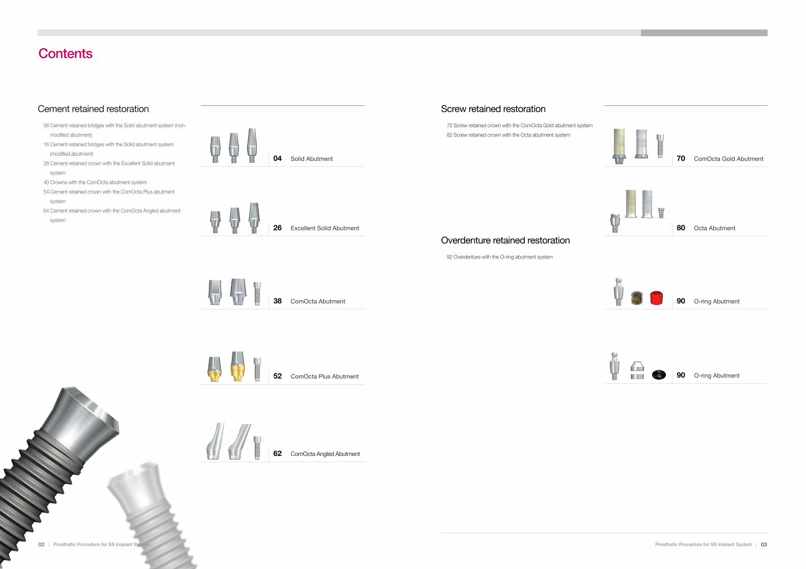
Cement retained restoration
06 Cement-retained bridges with the Solid abutment system (non-
modified abutment)
16 Cement-retained bridges with the Solid abutment system
(modified abutment)
28 Cement-retained crown with the Excellent Solid abutment
system
40 Crowns with the ComOcta abutment system
54 Cement retained crown with the ComOcta Plus abutment
system
64 Cement retained crown with the ComOcta Angled abutment
system
04 Solid Abutment
26 Excellent Solid Abutment
38 ComOcta Abutment
52 ComOcta Plus Abutment
62 ComOcta Angled Abutment
Screw retained restoration
72 Screw retained crown with the ComOcta Gold abutment system
82 Screw retained crown with the Octa abutment system
Overdenture retained restoration
92 Overdenture with the O-ring abutment system
70 ComOcta Gold Abutment
80 Octa Abutment
90 O-ring Abutment
90 O-ring Abutment
TS Implant SystemContents
Prosthetic Procedure for SS Implant System | 05
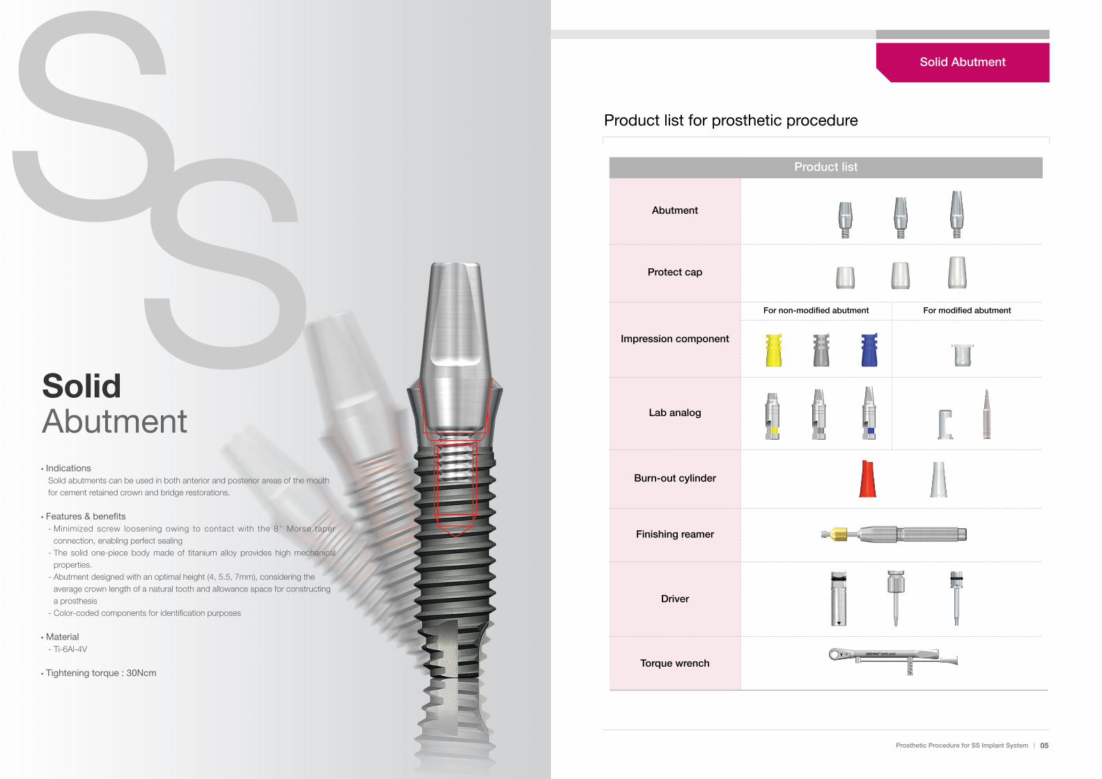
Product list
Abutment
Protect cap
Impression component
Lab analog
Burn-out cylinder
Finishing reamer
Driver
Torque wrench
Product list for prosthetic procedure
For non-modified abutment For modified abutment
�IndicationsSolid abutments can be used in both anterior and posterior areas of the mouthfor cement retained crown and bridge restorations.
�Features & benefits- Minimized screw loosening owing to contact with the 8�Morse taper
connection, enabling perfect sealing- The solid one-piece body made of titanium alloy provides high mechanical
properties.- Abutment designed with an optimal height (4, 5.5, 7mm), considering the
average crown length of a natural tooth and allowance space for constructinga prosthesis
- Color-coded components for identification purposes
�Material- Ti-6Al-4V
�Tightening torque : 30Ncm
SSSolid Abutment
Solid Abutment
Prosthetic Procedure for SS Implant System | 0706 | Prosthetic Procedure for SS Implant System06 _ OSSTEM
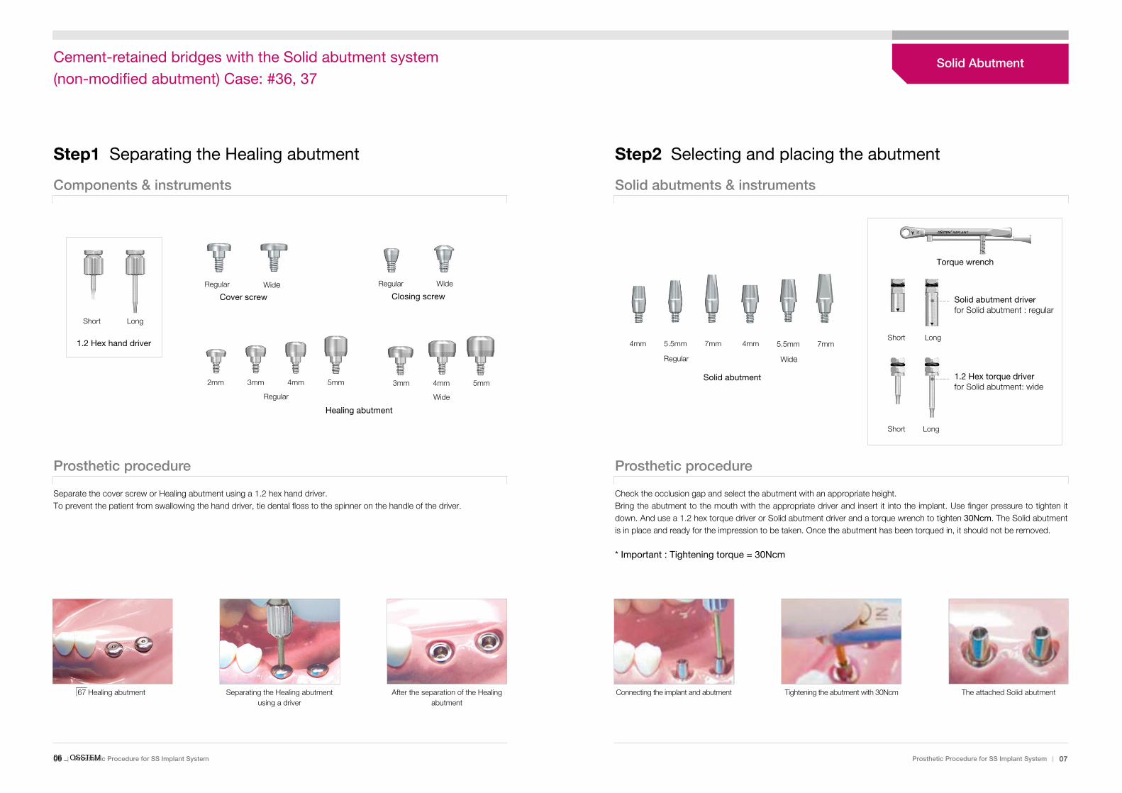
Step1 Separating the Healing abutment Step2 Selecting and placing the abutment
Components & instruments Solid abutments & instruments
Prosthetic procedure
Short
Regular
2mm 3mm 4mm 5mm 3mm 4mm 5mm
Wide
Regular Wide
Long
1.2 Hex hand driver
Solid abutment
Cover screw
Regular
Closing screw
Regular Wide
Healing abutment
4mm 5.5mm 7mm 4mm 5.5mm 7mm
Separate the cover screw or Healing abutment using a 1.2 hex hand driver. To prevent the patient from swallowing the hand driver, tie dental floss to the spinner on the handle of the driver.
67 Healing abutment Separating the Healing abutmentusing a driver
After the separation of the Healingabutment
Prosthetic procedure
Check the occlusion gap and select the abutment with an appropriate height.Bring the abutment to the mouth with the appropriate driver and insert it into the implant. Use finger pressure to tighten itdown. And use a 1.2 hex torque driver or Solid abutment driver and a torque wrench to tighten 30Ncm. The Solid abutmentis in place and ready for the impression to be taken. Once the abutment has been torqued in, it should not be removed.
* Important : Tightening torque = 30Ncm
Connecting the implant and abutment Tightening the abutment with 30Ncm The attached Solid abutment
Wide
Short Long
LongShort
1.2 Hex torque driver for Solid abutment: wide
Solid abutment driverfor Solid abutment : regular
Torque wrench
Solid AbutmentCement-retained bridges with the Solid abutment system (non-modified abutment) Case: #36, 37

08 | Prosthetic Procedure for SS Implant System Prosthetic Procedure for SS Implant System | 09
Step3 Taking the impression
Solid impression copings
Prosthetic procedure
Both the implant shoulder and the abutment must be cleaned of any blood or tissue prior to the impression procedure. If awide Solid abutment is used, the occlusal opening of the abutment must be sealed with wax or guttapercha.Select an impression coping that is the same size of the abutment and align the flat surface of the Solid abutment with theupper projecting part of the impression coping and press until it is locked with a clicking sound. And then impression material is injected around the impression coping and an impression is taken.Check for any defect on the impression. Send it to the lab.
Placing the impression coping Injecting impression materialaround the impression coping
Finished the impression
Solid abutment driver foruse with Solid abutment:regular
Solid abutment : regularFor use with SS II, SS III fixture : regular
SS II, SS III fixture : regular
1.2 Hex torque driver foruse with Solid abutment : wide
Solid abutment : wideFor use with SS II, SS III, SS Ultra-widefixture : wide
SS II, SS III, SS Ultra-widefixture : wide
Using the Solid abutment driver:Align the groove of Sol idabutment(regular) with the arrow onthe driver shaft and insert theabutment into the driver.
Using the 1.2 hex torque driver : The 1.2 hex torque driver t ipconnects to the occlusal opening ofthe abutment
Color-coding :In order to facilitate identification,the Solid impression copings arecolor-coded :Height 4.0mm = yellowHeight 5.5mm = greyHeight 7.0mm = blue
Caution :Since the plastic impressionproducts are not steri l ized,treatment using a general reagentis recommended. Avoid high heator radioactivity to prevent loss ofelasticity and deformation.
Indicator for internalwedge
groove
Solid abutment instruments usage
Solid impression copingfor non-modified abutments
Yellow Grey Blue
7mm4mm
5.5mm
Solid Abutment
10 | Prosthetic Procedure for SS Implant System Prosthetic Procedure for SS Implant System | 11
Step4 Placing the protect cap Step5 Fabricating the working model
Solid protect caps Solid lab analogs
Prosthetic procedure
Regular Wide
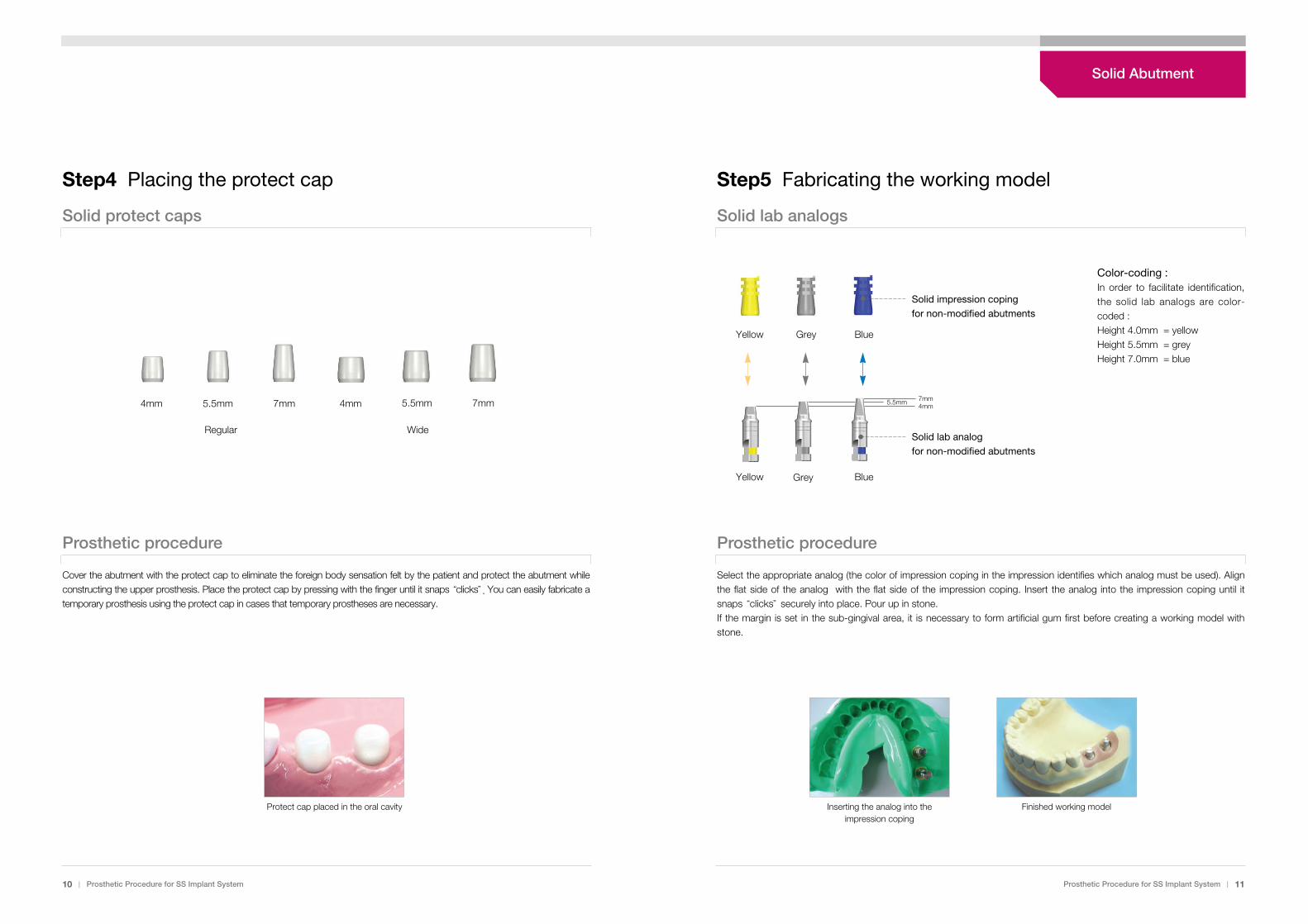
Cover the abutment with the protect cap to eliminate the foreign body sensation felt by the patient and protect the abutment whileconstructing the upper prosthesis. Place the protect cap by pressing with the finger until it snaps “clicks”. You can easily fabricate atemporary prosthesis using the protect cap in cases that temporary prostheses are necessary.
Protect cap placed in the oral cavity
Prosthetic procedure
Select the appropriate analog (the color of impression coping in the impression identifies which analog must be used). Alignthe flat side of the analog with the flat side of the impression coping. Insert the analog into the impression coping until itsnaps “clicks”securely into place. Pour up in stone.If the margin is set in the sub-gingival area, it is necessary to form artificial gum first before creating a working model withstone.
Inserting the analog into theimpression coping
Finished working model
4mm 5.5mm 7mm 4mm 7mm5.5mm
Yellow Grey
Solid impression copingfor non-modified abutments
Color-coding :In order to facilitate identification,the solid lab analogs are color-coded :Height 4.0mm = yellowHeight 5.5mm = greyHeight 7.0mm = blue
Blue
Solid lab analogfor non-modified abutments
7mm4mm
5.5mm
Yellow BlueGrey
Solid Abutment
12 | Prosthetic Procedure for SS Implant System Prosthetic Procedure for SS Implant System | 13
Step6 Wax up Step7 Casting and trimming
Solid burn-out cylinders Finishing reamer
Prosthetic procedure
Regular Wide
Analog on the working model Fastening the burn-outcylinder for the bridge
Wax-up
Prosthetic procedure
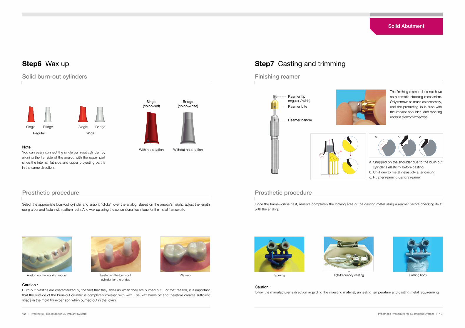
Once the framework is cast, remove completely the locking area of the casting metal using a reamer before checking its fitwith the analog.
Spruing High-frequency casting Casting body
Caution :Burn-out plastics are characterized by the fact that they swell up when they are burned out. For that reason, it is importantthat the outside of the burn-out cylinder is completely covered with wax. The wax burns off and therefore creates sufficientspace in the mold for expansion when burned out in the oven.
Single BridgeSingle Bridge
Note :You can easily connect the single burn-out cylinder byaligning the flat side of the analog with the upper partsince the internal flat side and upper projecting part isin the same direction.
Single(color=red)
Bridge(color=white)
With antirotation Without antirotation
Reamer handle
Reamer bite
Reamer tip(regular / wide)
The finishing reamer does not havean automatic stopping mechanism.Only remove as much as necessary,until the protruding lip is flush withthe implant shoulder. And workingunder a stereomicroscope.
a. Snapped on the shoulder due to the burn-outcylinder’s elasticity before casting
b. Unfit due to metal inelasticty after castingc. Fit after reaming using a reamer
Caution :follow the manufacturer s direction regarding the investing material, annealing temperature and casting metal requirements
Select the appropriate burn-out cylinder and snap it “clicks”over the analog. Based on the analog’s height, adjust the lengthusing a bur and fasten with pattern resin. And wax up using the conventional technique for the metal framework.
a. b. c.
Solid Abutment
14 | Prosthetic Procedure for SS Implant System Prosthetic Procedure for SS Implant System | 15
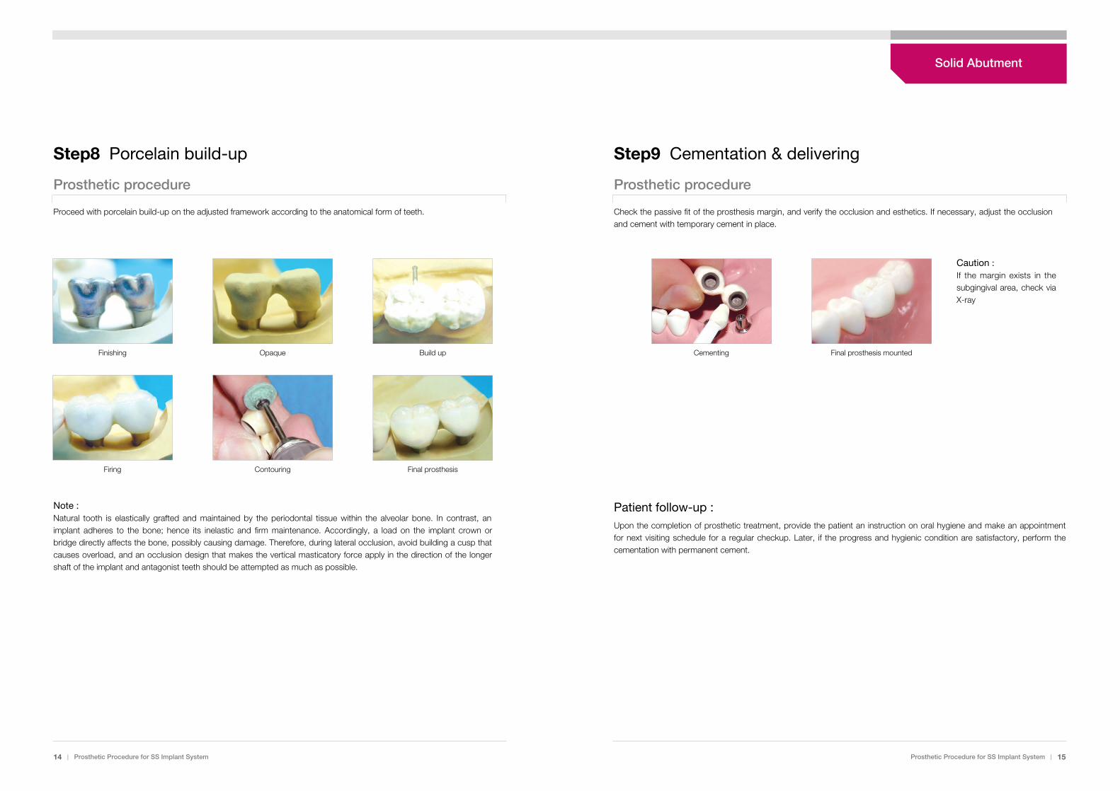
Check the passive fit of the prosthesis margin, and verify the occlusion and esthetics. If necessary, adjust the occlusionand cement with temporary cement in place.
Patient follow-up :Upon the completion of prosthetic treatment, provide the patient an instruction on oral hygiene and make an appointmentfor next visiting schedule for a regular checkup. Later, if the progress and hygienic condition are satisfactory, perform thecementation with permanent cement.
Step8 Porcelain build-up Step9 Cementation & delivering
Prosthetic procedure Prosthetic procedure
Proceed with porcelain build-up on the adjusted framework according to the anatomical form of teeth.
Note :Natural tooth is elastically grafted and maintained by the periodontal tissue within the alveolar bone. In contrast, animplant adheres to the bone; hence its inelastic and firm maintenance. Accordingly, a load on the implant crown orbridge directly affects the bone, possibly causing damage. Therefore, during lateral occlusion, avoid building a cusp thatcauses overload, and an occlusion design that makes the vertical masticatory force apply in the direction of the longershaft of the implant and antagonist teeth should be attempted as much as possible.
Caution : If the margin exists in thesubgingival area, check viaX-ray
Cementing Final prosthesis mountedFinishing Opaque Build up
Firing Contouring Final prosthesis
Solid Abutment
Step2 Selecting and placing the abutment
Solid abutments & instruments
Step1 Separating the Healing abutment
Components & instruments
16 | Prosthetic Procedure for SS Implant System Prosthetic Procedure for SS Implant System | 17
Prosthetic procedure
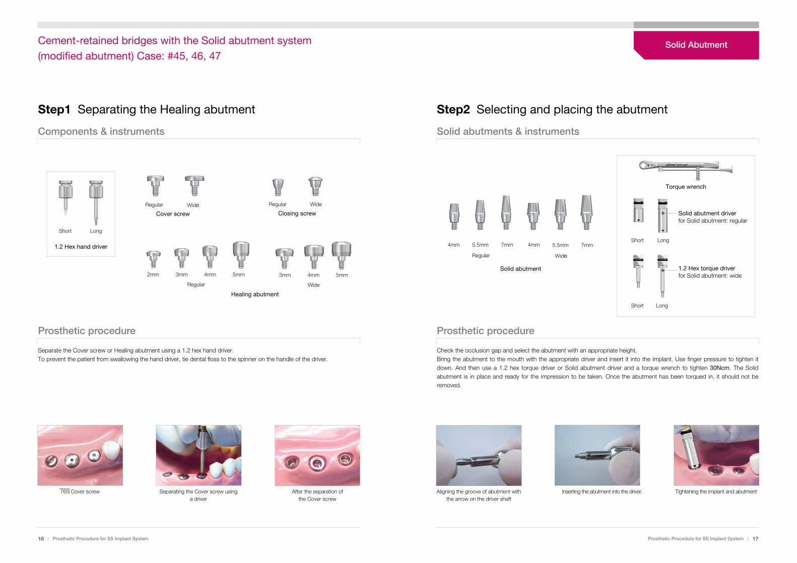
Separate the Cover screw or Healing abutment using a 1.2 hex hand driver.To prevent the patient from swallowing the hand driver, tie dental floss to the spinner on the handle of the driver.
765 Cover screw Separating the Cover screw usinga driver
After the separation of the Cover screw
Prosthetic procedure
Check the occlusion gap and select the abutment with an appropriate height. Bring the abutment to the mouth with the appropriate driver and insert it into the implant. Use finger pressure to tighten itdown. And then use a 1.2 hex torque driver or Solid abutment driver and a torque wrench to tighten 30Ncm. The Solidabutment is in place and ready for the impression to be taken. Once the abutment has been torqued in, it should not beremoved.
Aligning the groove of abutment withthe arrow on the driver shaft
Inserting the abutment into the driver. Tightening the implant and abutment
Regular Wide
Solid abutment
4mm 5.5mm 7mm 4mm 5.5mm 7mm
Short Long
LongShort
1.2 Hex torque driver for Solid abutment: wide
Solid abutment driverfor Solid abutment: regular
Short
2mm 3mm 4mm 5mm
Long
1.2 Hex hand driver
Regular
Healing abutment
3mm 4mm 5mm
Wide
Regular WideCover screw
Regular
Closing screw
Wide
Torque wrench
Solid AbutmentCement-retained bridges with the Solid abutment system(modified abutment) Case: #45, 46, 47
Step3 Adjusting the path and taking the impression
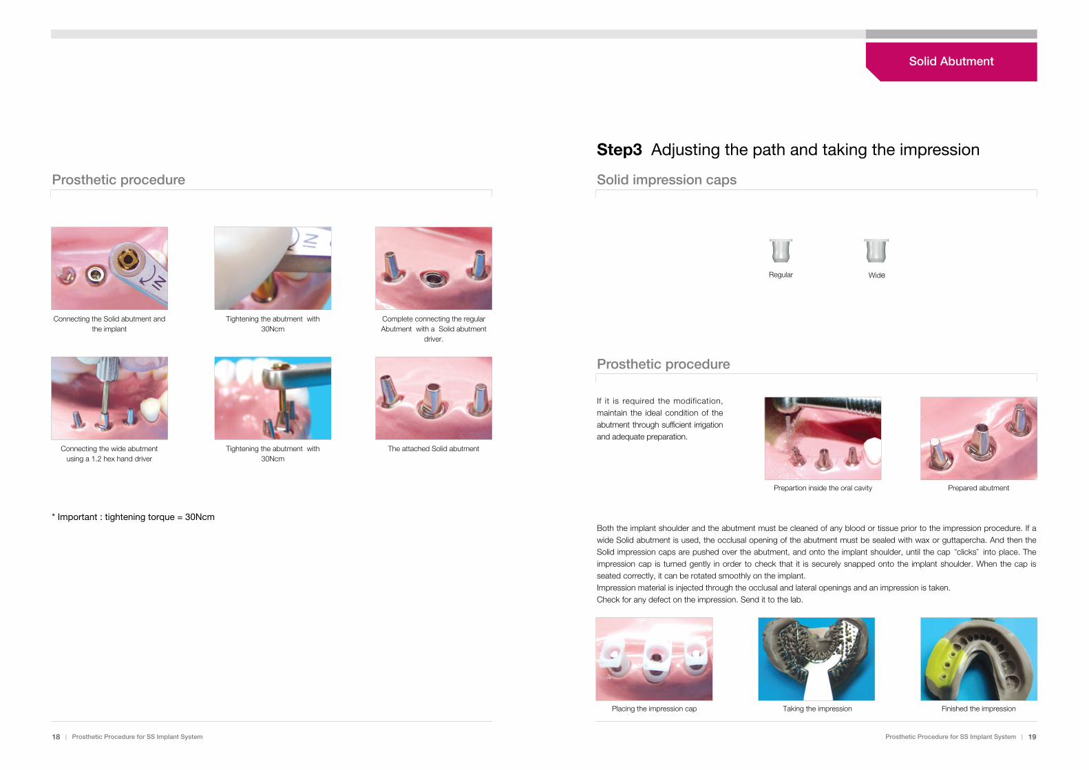
Solid impression capsProsthetic procedure
Prosthetic procedure
If it is required the modification,maintain the ideal condition of theabutment through sufficient irrigationand adequate preparation.
Both the implant shoulder and the abutment must be cleaned of any blood or tissue prior to the impression procedure. If awide Solid abutment is used, the occlusal opening of the abutment must be sealed with wax or guttapercha. And then theSolid impression caps are pushed over the abutment, and onto the implant shoulder, until the cap “clicks”into place. Theimpression cap is turned gently in order to check that it is securely snapped onto the implant shoulder. When the cap isseated correctly, it can be rotated smoothly on the implant.Impression material is injected through the occlusal and lateral openings and an impression is taken.Check for any defect on the impression. Send it to the lab.
Placing the impression cap Taking the impression Finished the impression
Prepartion inside the oral cavity Prepared abutment
18 | Prosthetic Procedure for SS Implant System Prosthetic Procedure for SS Implant System | 19
* Important : tightening torque = 30Ncm
Connecting the Solid abutment andthe implant
Tightening the abutment with30Ncm
Complete connecting the regularAbutment with a Solid abutment
driver.
Connecting the wide abutmentusing a 1.2 hex hand driver
Tightening the abutment with30Ncm
The attached Solid abutment
Regular Wide
Solid Abutment
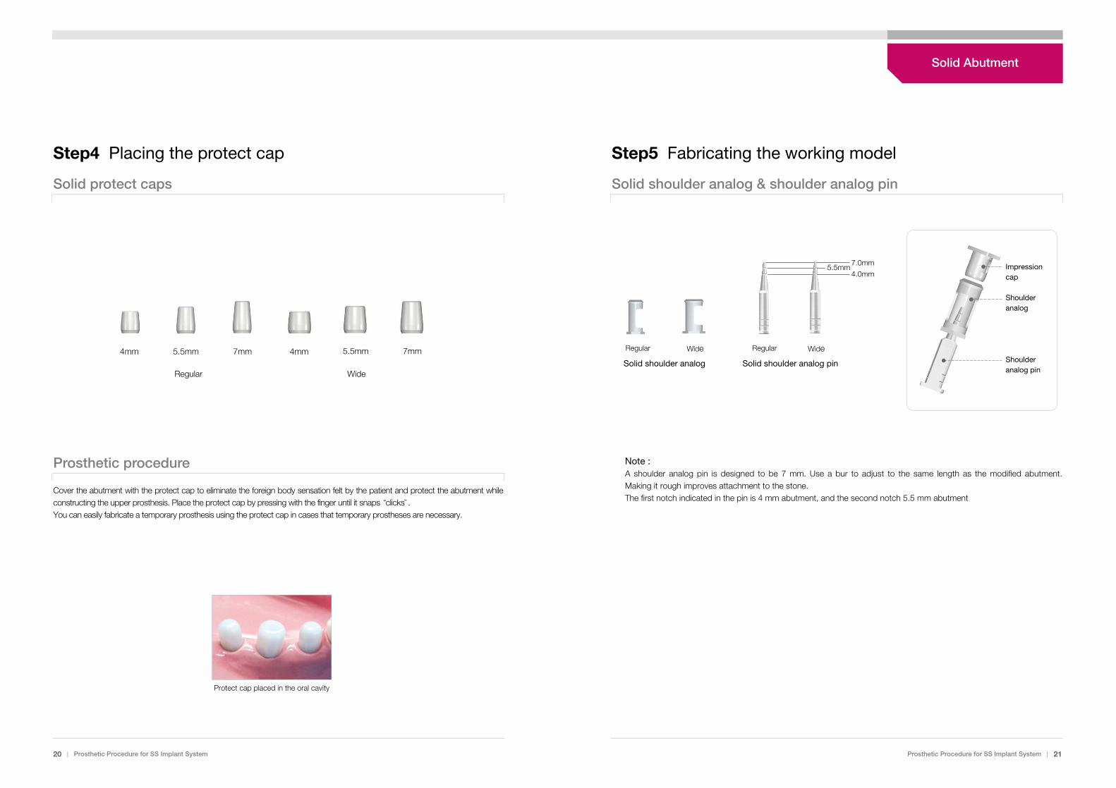
Step5 Fabricating the working model
Solid shoulder analog & shoulder analog pin
20 | Prosthetic Procedure for SS Implant System Prosthetic Procedure for SS Implant System | 21
Step4 Placing the protect cap
Solid protect caps
Prosthetic procedure
Cover the abutment with the protect cap to eliminate the foreign body sensation felt by the patient and protect the abutment whileconstructing the upper prosthesis. Place the protect cap by pressing with the finger until it snaps “clicks”.You can easily fabricate a temporary prosthesis using the protect cap in cases that temporary prostheses are necessary.
Protect cap placed in the oral cavity
Note : A shoulder analog pin is designed to be 7 mm. Use a bur to adjust to the same length as the modified abutment.Making it rough improves attachment to the stone.The first notch indicated in the pin is 4 mm abutment, and the second notch 5.5 mm abutment
7.0mm
4.0mm5.5mm
Regular Wide Regular Wide
Solid shoulder analog Solid shoulder analog pin
Impressioncap
Shoulderanalog
Shoulderanalog pinRegular Wide
4mm 5.5mm 7mm 4mm 7mm5.5mm
Solid Abutment
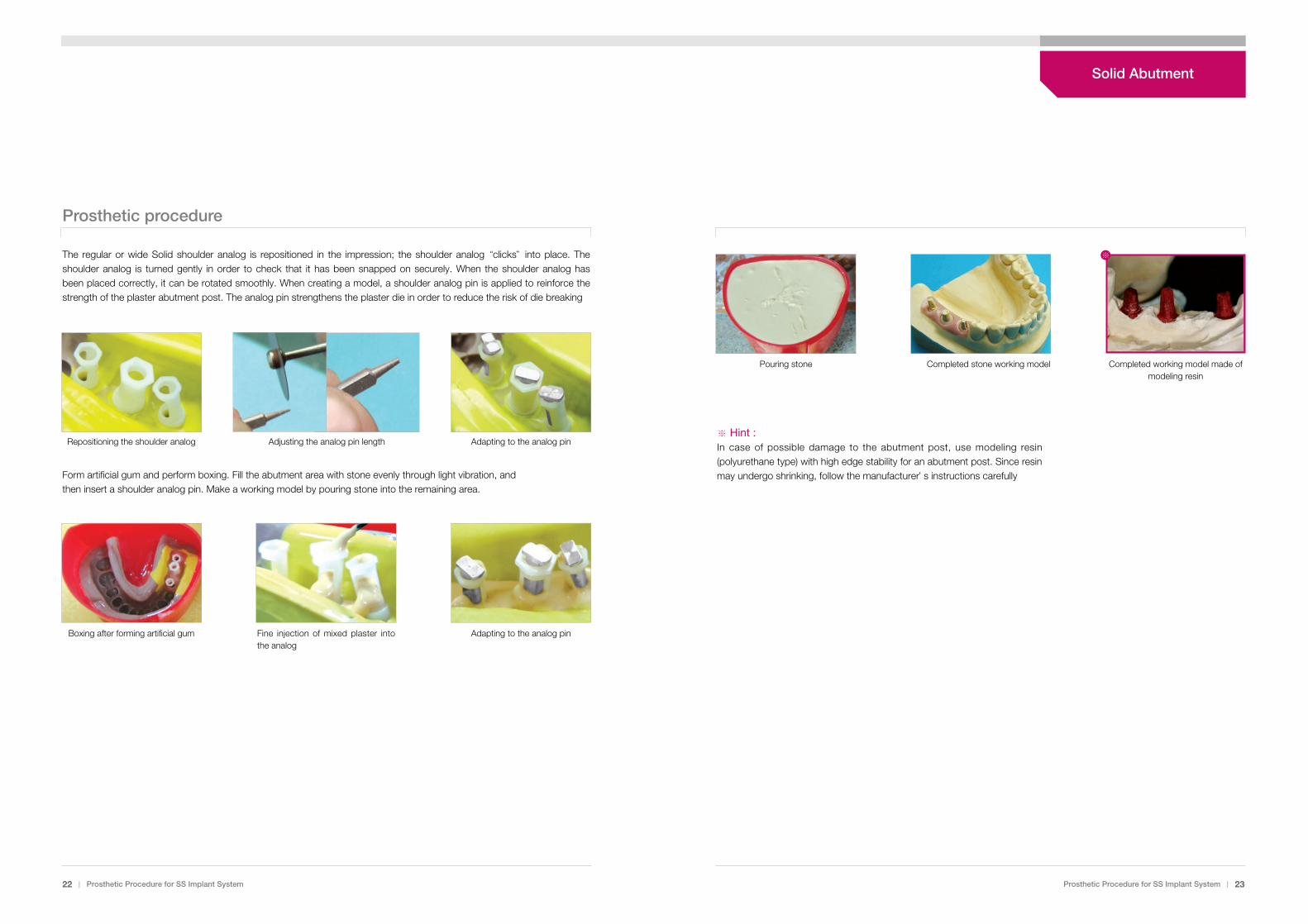
Prosthetic procedure
Form artificial gum and perform boxing. Fill the abutment area with stone evenly through light vibration, andthen insert a shoulder analog pin. Make a working model by pouring stone into the remaining area.
22 | Prosthetic Procedure for SS Implant System Prosthetic Procedure for SS Implant System | 23
※ Hint :In case of possible damage to the abutment post, use modeling resin(polyurethane type) with high edge stability for an abutment post. Since resinmay undergo shrinking, follow the manufacturer’s instructions carefully
Boxing after forming artificial gum Fine injection of mixed plaster intothe analog
Adapting to the analog pin
Pouring stone Completed stone working model Completed working model made ofmodeling resin
※The regular or wide Solid shoulder analog is repositioned in the impression; the shoulder analog “clicks”into place. Theshoulder analog is turned gently in order to check that it has been snapped on securely. When the shoulder analog hasbeen placed correctly, it can be rotated smoothly. When creating a model, a shoulder analog pin is applied to reinforce thestrength of the plaster abutment post. The analog pin strengthens the plaster die in order to reduce the risk of die breaking
Repositioning the shoulder analog Adjusting the analog pin length Adapting to the analog pin
Solid Abutment

24 | Prosthetic Procedure for SS Implant System
Prosthetic procedure
Check the passive fit of the prosthesis margin, and verify the occlusion and esthetics. If necessary, adjust the occlusion andcement with temporary cement in place.
Patient follow-up :Upon the completion of prosthetic treatment, provide the patient an instruction on oral hygiene and make anappointment for next visiting schedule for a regular checkup. Later, if the progress and hygienic conditionare satisfactory, perform the cementation with permanent cement.
Step7 Cementation & delivering
Cementing Mounting the final prosthesis
Prosthetic Procedure for SS Implant System | 25
Caution : If the margin exists in thesubgingival area, check via X-ray
Step6 Framework & porcelain build-up
Solid burn-out cylinders
Prosthetic procedure
The framework and ceramic build-up procedures are the same as steps 6~8 for Solid abutment (non-modified abutment)
Fastening the plastic coping forthe bridge
Adjusting the length using abur
Resin application Waxing up
Spruing Casting body Reaming Finishing
Opaque Build-up Firing Final prosthesis
Single BridgeSingle Bridge
Regular Wide
Solid Abutment
Prosthetic Procedure for SS Implant System | 27
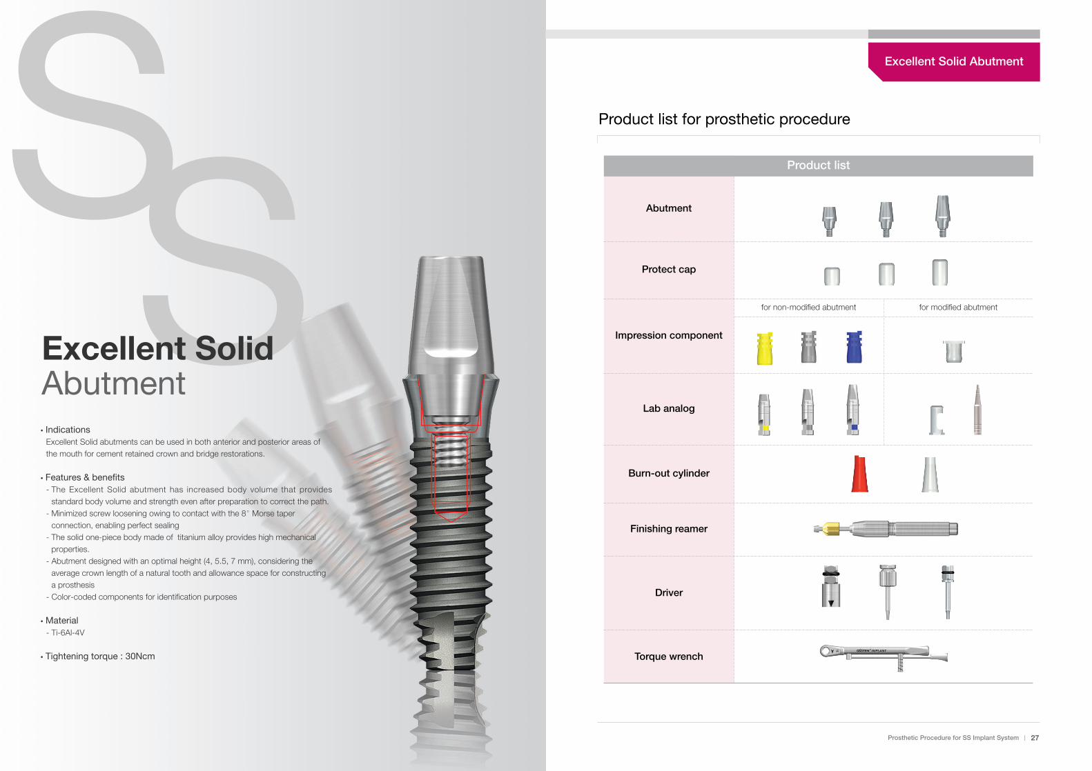
�IndicationsExcellent Solid abutments can be used in both anterior and posterior areas ofthe mouth for cement retained crown and bridge restorations.
�Features & benefits- The Excellent Solid abutment has increased body volume that provides
standard body volume and strength even after preparation to correct the path. - Minimized screw loosening owing to contact with the 8�Morse taper
connection, enabling perfect sealing - The solid one-piece body made of titanium alloy provides high mechanical
properties.- Abutment designed with an optimal height (4, 5.5, 7 mm), considering the
average crown length of a natural tooth and allowance space for constructinga prosthesis
- Color-coded components for identification purposes
�Material- Ti-6Al-4V
�Tightening torque : 30Ncm
SSExcellent SolidAbutment
Product list
Abutment
Protect cap
Impression component
Lab analog
Burn-out cylinder
Finishing reamer
Driver
Torque wrench
Product list for prosthetic procedure
for non-modified abutment for modified abutment
Excellent Solid Abutment
3mm 4mm 5mm
Wide
Step2 Selecting and placing the abutment
Prosthetic procedure
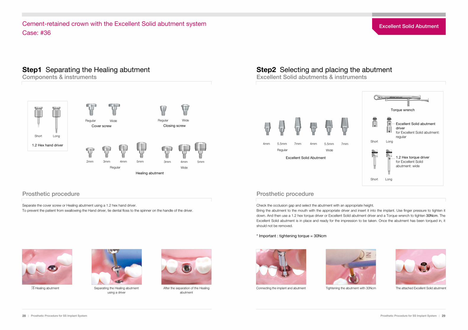
Check the occlusion gap and select the abutment with an appropriate height. Bring the abutment to the mouth with the appropriate driver and insert it into the implant. Use finger pressure to tighten itdown. And then use a 1.2 hex torque driver or Excellent Solid abutment driver and a Torque wrench to tighten 30Ncm. TheExcellent Solid abutment is in place and ready for the impression to be taken. Once the abutment has been torqued in, itshould not be removed.
* Important : tightening torque = 30Ncm
Connecting the implant and abutment Tightening the abutment with 30Ncm The attached Excellent Solid abutment
Step1 Separating the Healing abutment
Prosthetic procedure
Separate the cover screw or Healing abutment using a 1.2 hex hand driver.To prevent the patient from swallowing the Hand driver, tie dental floss to the spinner on the handle of the driver.
28 | Prosthetic Procedure for SS Implant System Prosthetic Procedure for SS Implant System | 29
Components & instruments Excellent Solid abutments & instruments
6 Healing abutment Separating the Healing abutmentusing a driver
After the separation of the Healingabutment
Regular Wide
Excellent Solid Abutment
4mm 5.5mm 7mm 4mm 5.5mm 7mm
Short Long
LongShort
1.2 Hex torque driver for Excellent Solidabutment: wide
Excellent Solid abutmentdriverfor Excellent Solid abutment:regularShort
2mm 3mm 4mm 5mm
Long
1.2 Hex hand driver
Regular
Healing abutment
Regular WideCover screw
Regular
Closing screw
Wide
Torque wrench
Excellent Solid AbutmentCement-retained crown with the Excellent Solid abutment systemCase: #36

Step3 Taking the impression
Features of Excellent Solid abutment:The Excellent Solid abutment has increased bodyvolume that provides appropriate body volume andstrength even after preparation to correct. For gold restoration, the amount of precious metal isreducible based on the increased volume. As such, itis economic, and direct impression taking is easy. Theprocedure for prosthesis is the same as that for a Solidabutment.
Design of Excellent Solid abutment connection :The Excellent Solid abutment is structured such thatits Morse taper area (B) is always in contact to preventscrew loosening or fracture. In case the gap in theconnection part (A) is in contact, the Morse taper maynot come into contact.
30 | Prosthetic Procedure for SS Implant System Prosthetic Procedure for SS Implant System | 31
Excellent Solid abutment...
Solid abutment
Regular Height = 5.5mm
Sectional view ofthe assembly
Enlarged view of A Enlarged view of B
Excellent Solid abutment
Regular Height = 5.5mm
Precision fitness picture of the Excellent Solid abutment Prosthetic procedure
Both the implant shoulder and the abutment must be cleaned of any blood or tissue prior to the impression procedure. If awide Excellent Solid abutment is used, the occlusal opening of the abutment must be sealed with wax or guttapercha.Select an impression coping that is the same size of the abutment and align the flat surface of the Excellent Solid abutmentwith the upper projecting part of the impression coping and press until it is locked with a clicking sound. And then impression material is injected around the impression coping and an impression is taken.Check for any defect on the impression. Send it to the lab.
Placing the impression coping Injecting impression material aroundthe impression coping
Finished the impression
VS.
Excellent Solid impression copings
Yellow Grey
Excellent Solid impression copingfor non-modified abutments
Color-coding :In order to facilitate identification,the Excellent Solid impressioncopings are color-coded :Height 4.0mm = yellowHeight 5.5mm = greyHeight 7.0mm = blue
Caution :Since the plastic impressionproducts are not steri l ized,treatment using a general reagentis recommended. Avoid high heator radioactivity to prevent loss ofelasticity and deformation.
7mm4mm
5.5mm
Blue
A
A B
B
Gap
:0.1
Excellent Solid Abutment
Step5 Fabricating the working model
Prosthetic procedure
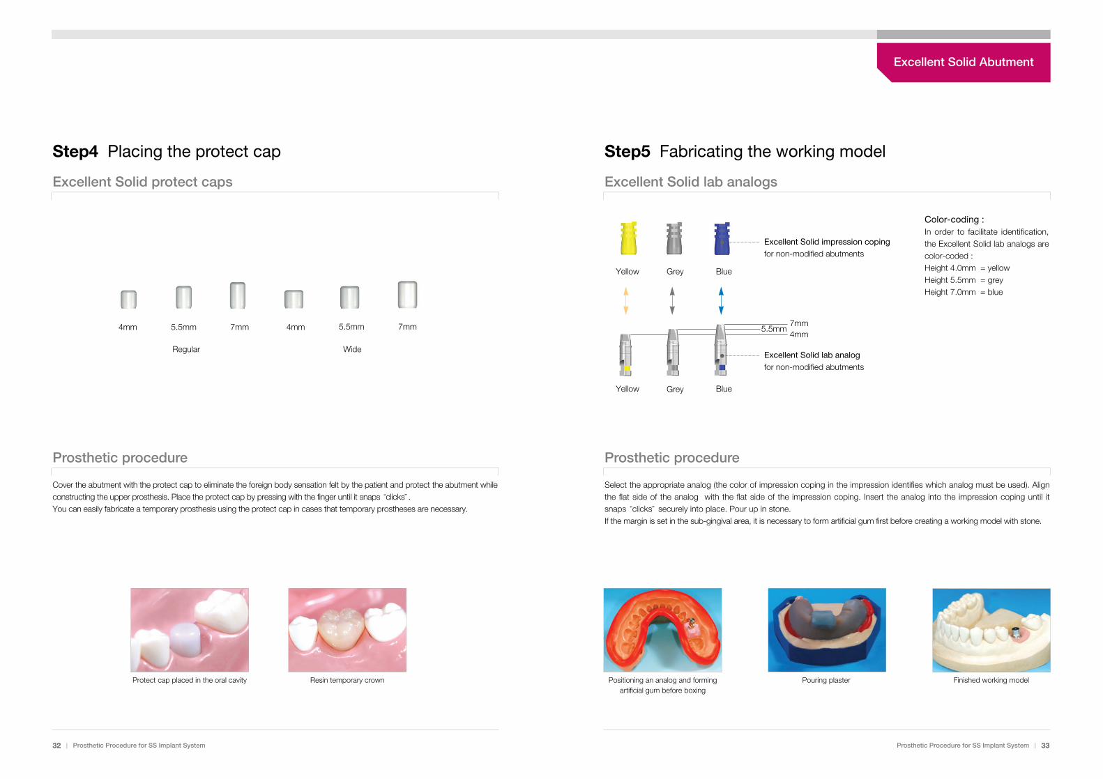
Select the appropriate analog (the color of impression coping in the impression identifies which analog must be used). Alignthe flat side of the analog with the flat side of the impression coping. Insert the analog into the impression coping until itsnaps “clicks”securely into place. Pour up in stone.If the margin is set in the sub-gingival area, it is necessary to form artificial gum first before creating a working model with stone.
Positioning an analog and formingartificial gum before boxing
Pouring plaster Finished working modelProtect cap placed in the oral cavity Resin temporary crown
32 | Prosthetic Procedure for SS Implant System Prosthetic Procedure for SS Implant System | 33
Step4 Placing the protect cap
Excellent Solid protect caps
Prosthetic procedure
Regular Wide
Cover the abutment with the protect cap to eliminate the foreign body sensation felt by the patient and protect the abutment whileconstructing the upper prosthesis. Place the protect cap by pressing with the finger until it snaps “clicks”.You can easily fabricate a temporary prosthesis using the protect cap in cases that temporary prostheses are necessary.
4mm 5.5mm 7mm 4mm 7mm5.5mm
Excellent Solid lab analogs
Yellow Grey
Excellent Solid impression copingfor non-modified abutments
Excellent Solid lab analogfor non-modified abutments
Color-coding :In order to facilitate identification,the Excellent Solid lab analogs arecolor-coded :Height 4.0mm = yellowHeight 5.5mm = greyHeight 7.0mm = blue
7mm4mm
5.5mm
Blue
Yellow BlueGrey
Excellent Solid Abutment

Step6 Wax up
Excellent Solid burn-out cylinders
Prosthetic procedure
Select the appropriate burn-out cylinder and snap it “clicks”over the analog. Adjust the length according to the height ofthe analog and perform the wax-up procedure for the occlusal surface and resin facing.
Analog on the working model Fastening the single burn-out cylinder Adjusting the length using a bur
34 | Prosthetic Procedure for SS Implant System Prosthetic Procedure for SS Implant System | 35
Regular Wide
Single BridgeSingle Bridge
Note :You can easily connect the single burn-out cylinder byaligning the flat side of the analog with the upper partsince the internal flat side and upper projecting part isin the same direction.
Single(color=red)
Bridge(color=white)
with antirotation without antirotation
Prosthetic procedure
Caution :Burn-out plastics are characterized by the fact that they swell up when they are burned out. For that reason, it isimportant that the outside of the burn-out cylinder is completely covered with wax. The wax burns off and thereforecreates sufficient space in the mold for expansion when burned out in the oven.
Completed adjustment Wax-up procedure Labial surface opening
Coating adhesive Beading Spruing
Excellent Solid Abutment
Step8 Selecting and placing the abutment
Prosthetic procedure
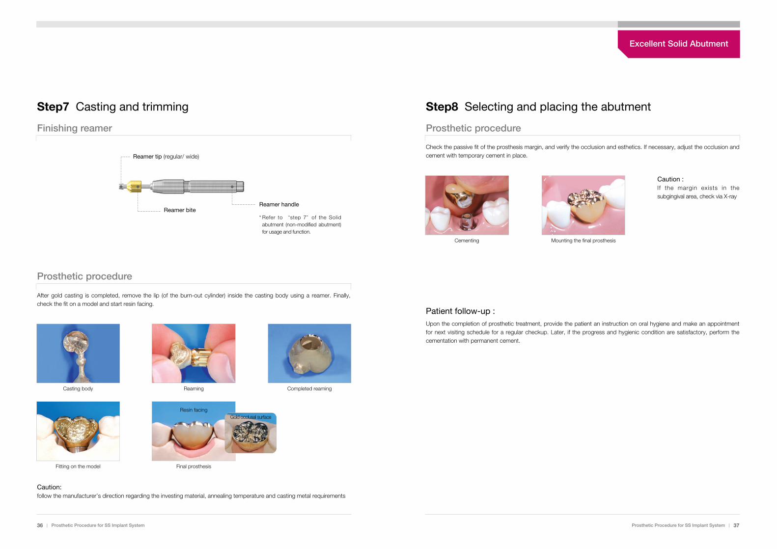
Check the passive fit of the prosthesis margin, and verify the occlusion and esthetics. If necessary, adjust the occlusion andcement with temporary cement in place.
Caution : If the margin exists in thesubgingival area, check via X-ray
Patient follow-up :Upon the completion of prosthetic treatment, provide the patient an instruction on oral hygiene and make an appointmentfor next visiting schedule for a regular checkup. Later, if the progress and hygienic condition are satisfactory, perform thecementation with permanent cement.
Cementing Mounting the final prosthesis
Step7 Casting and trimming
Finishing reamer
Prosthetic procedure
After gold casting is completed, remove the lip (of the burn-out cylinder) inside the casting body using a reamer. Finally,check the fit on a model and start resin facing.
Caution:follow the manufacturer’s direction regarding the investing material, annealing temperature and casting metal requirements
Fitting on the model Final prosthesis
Resin facingGold occlusal surface
Casting body Reaming Completed reaming
36 | Prosthetic Procedure for SS Implant System Prosthetic Procedure for SS Implant System | 37
Reamer biteReamer handle
Reamer tip (regular/ wide)
* Refer to “step 7”of the Solidabutment (non-modified abutment)for usage and function.
Excellent Solid Abutment
Prosthetic Procedure for SS Implant System | 39
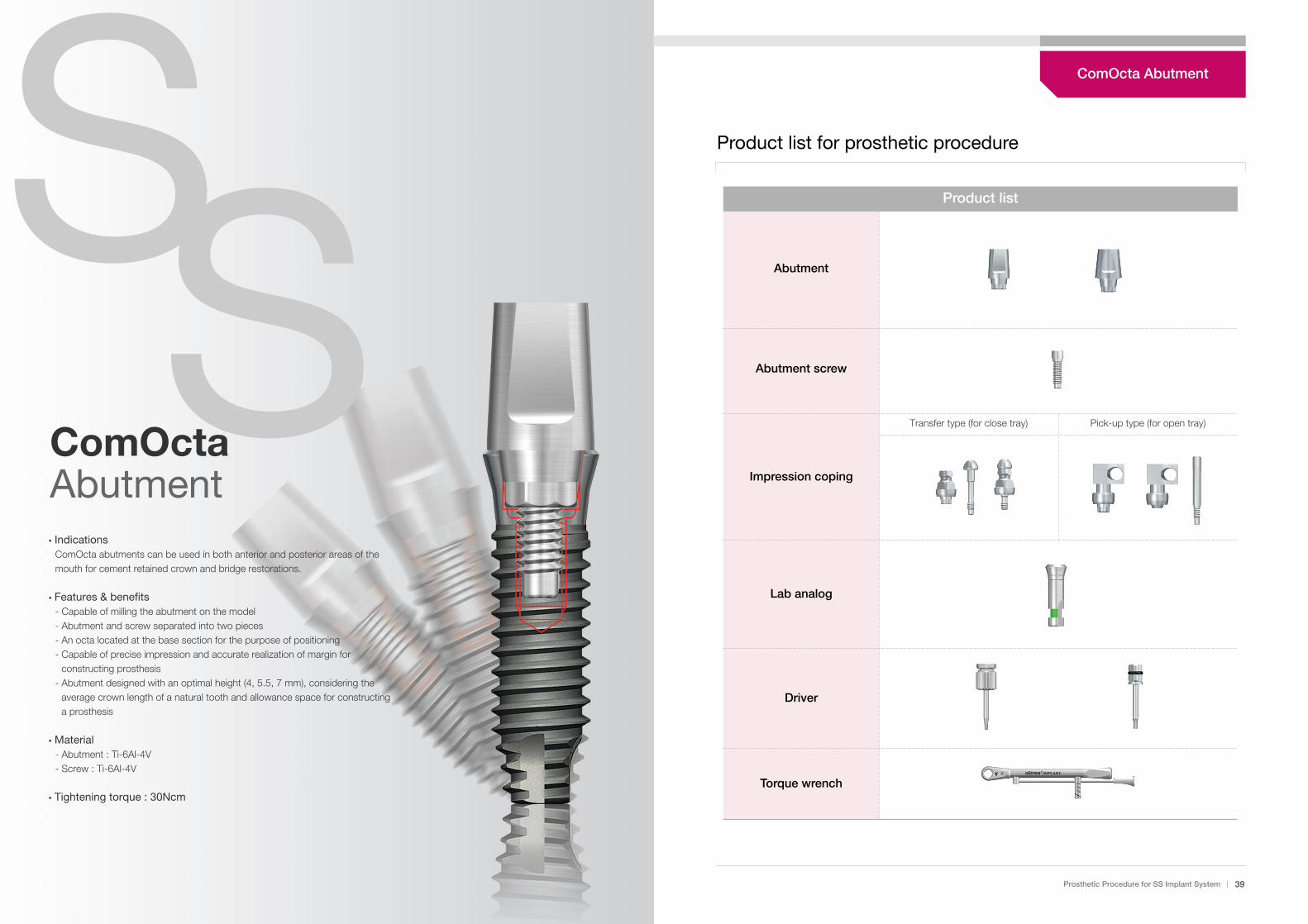
Product list
Abutment
Abutment screw
Impression coping
Lab analog
Driver
Torque wrench
Product list for prosthetic procedure
Transfer type (for close tray) Pick-up type (for open tray)
�IndicationsComOcta abutments can be used in both anterior and posterior areas of themouth for cement retained crown and bridge restorations.
�Features & benefits- Capable of milling the abutment on the model- Abutment and screw separated into two pieces- An octa located at the base section for the purpose of positioning- Capable of precise impression and accurate realization of margin for
constructing prosthesis- Abutment designed with an optimal height (4, 5.5, 7 mm), considering the
average crown length of a natural tooth and allowance space for constructinga prosthesis
�Material- Abutment : Ti-6Al-4V- Screw : Ti-6Al-4V
�Tightening torque : 30Ncm
SSComOcta Abutment
ComOcta Abutment
Step2 Connecting the impression copingStep1 Separating the Healing abutment
40 | Prosthetic Procedure for SS Implant System Prosthetic Procedure for SS Implant System | 41
Components & instruments Impression system
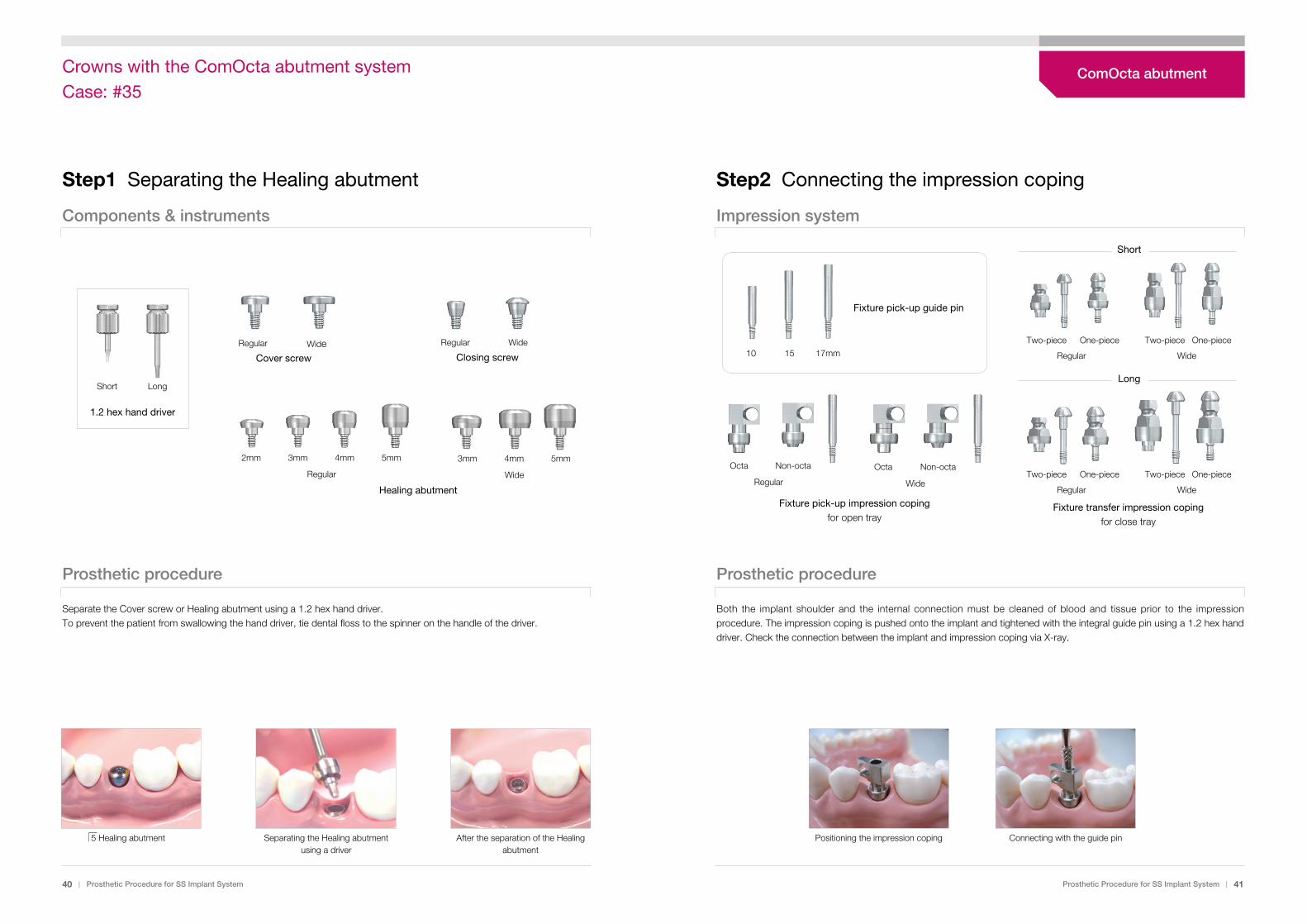
Prosthetic procedure
Separate the Cover screw or Healing abutment using a 1.2 hex hand driver.To prevent the patient from swallowing the hand driver, tie dental floss to the spinner on the handle of the driver.
5 Healing abutment Separating the Healing abutmentusing a driver
After the separation of the Healingabutment
Prosthetic procedure
Both the implant shoulder and the internal connection must be cleaned of blood and tissue prior to the impressionprocedure. The impression coping is pushed onto the implant and tightened with the integral guide pin using a 1.2 hex handdriver. Check the connection between the implant and impression coping via X-ray.
Positioning the impression coping Connecting with the guide pin
Octa Non-octa Octa Non-octa
Two-piece One-piece
Regular
Two-piece One-piece
Wide
Two-piece One-piece
Regular
Two-piece One-piece
WideRegular Wide
10 15 17mm
Short
Fixture transfer impression copingfor close tray
Fixture pick-up impression copingfor open tray
Fixture pick-up guide pin
LongShort
2mm 3mm 4mm 5mm
Long
1.2 hex hand driver
Regular
Healing abutment
3mm 4mm 5mm
Wide
Regular WideCover screw
Regular
Closing screw
Wide
ComOcta abutmentCrowns with the ComOcta abutment systemCase: #35
Step4 Fixing the Fixture lab analog
Fixture lab analogs
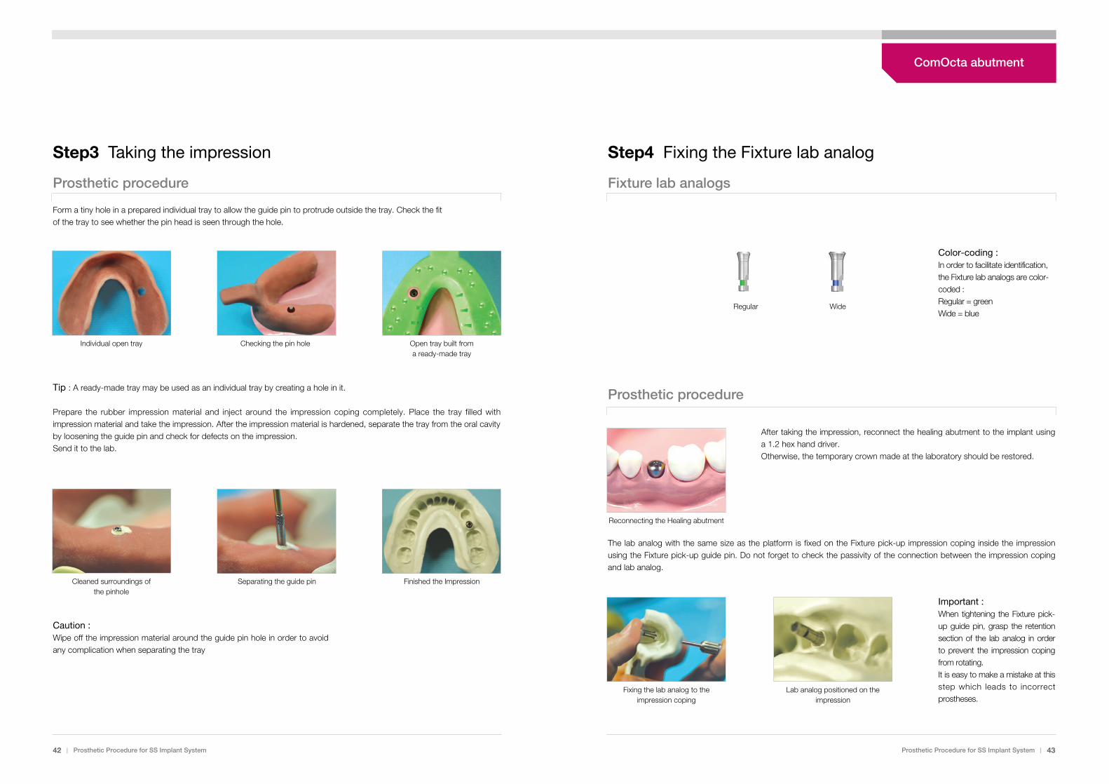
Prosthetic procedure
After taking the impression, reconnect the healing abutment to the implant usinga 1.2 hex hand driver.Otherwise, the temporary crown made at the laboratory should be restored.
The lab analog with the same size as the platform is fixed on the Fixture pick-up impression coping inside the impressionusing the Fixture pick-up guide pin. Do not forget to check the passivity of the connection between the impression copingand lab analog.
Important : When tightening the Fixture pick-up guide pin, grasp the retentionsection of the lab analog in orderto prevent the impression copingfrom rotating. It is easy to make a mistake at thisstep which leads to incorrectprostheses.
Reconnecting the Healing abutment
Fixing the lab analog to theimpression coping
Lab analog positioned on theimpression
Step3 Taking the impression
Prosthetic procedure
Form a tiny hole in a prepared individual tray to allow the guide pin to protrude outside the tray. Check the fitof the tray to see whether the pin head is seen through the hole.
Tip : A ready-made tray may be used as an individual tray by creating a hole in it.
Prepare the rubber impression material and inject around the impression coping completely. Place the tray filled withimpression material and take the impression. After the impression material is hardened, separate the tray from the oral cavityby loosening the guide pin and check for defects on the impression.Send it to the lab.
Caution : Wipe off the impression material around the guide pin hole in order to avoidany complication when separating the tray
Individual open tray Checking the pin hole Open tray built from a ready-made tray
Cleaned surroundings ofthe pinhole
Separating the guide pin Finished the Impression
42 | Prosthetic Procedure for SS Implant System Prosthetic Procedure for SS Implant System | 43
Color-coding :In order to facilitate identification,the Fixture lab analogs are color-coded :Regular = greenWide = blue
Regular Wide
ComOcta abutment
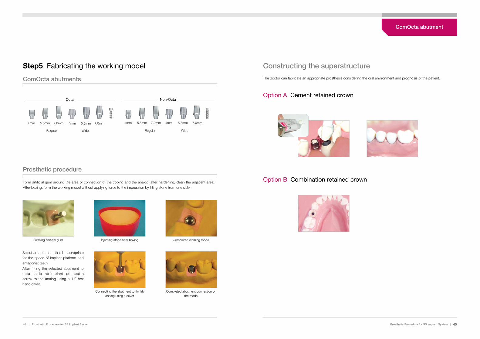
Constructing the superstructure
The doctor can fabricate an appropriate prosthesis considering the oral environment and prognosis of the patient.
Option A Cement retained crown
Option B Combination retained crown
Step5 Fabricating the working model
ComOcta abutments
Prosthetic procedure
Form artificial gum around the area of connection of the coping and the analog (after hardening, clean the adjacent area).After boxing, form the working model without applying force to the impression by filling stone from one side.
Forming artificial gum Injecting stone after boxing Completed working model
Select an abutment that is appropriatefor the space of implant platform andantagonist teeth.After fitting the selected abutment toocta inside the implant, connect ascrew to the analog using a 1.2 hexhand driver.
Connecting the abutment to thr labanalog using a driver
Completed abutment connection onthe model
44 | Prosthetic Procedure for SS Implant System Prosthetic Procedure for SS Implant System | 45
4mm 5.5mm 7.0mm 4mm 5.5mm 7.0mm
Octa
4mm 5.5mm 7.0mm 4mm 5.5mm 7.0mm
Non-Octa
Regular Wide Regular Wide
ComOcta abutment
Step7 Casting & porcelain build-up
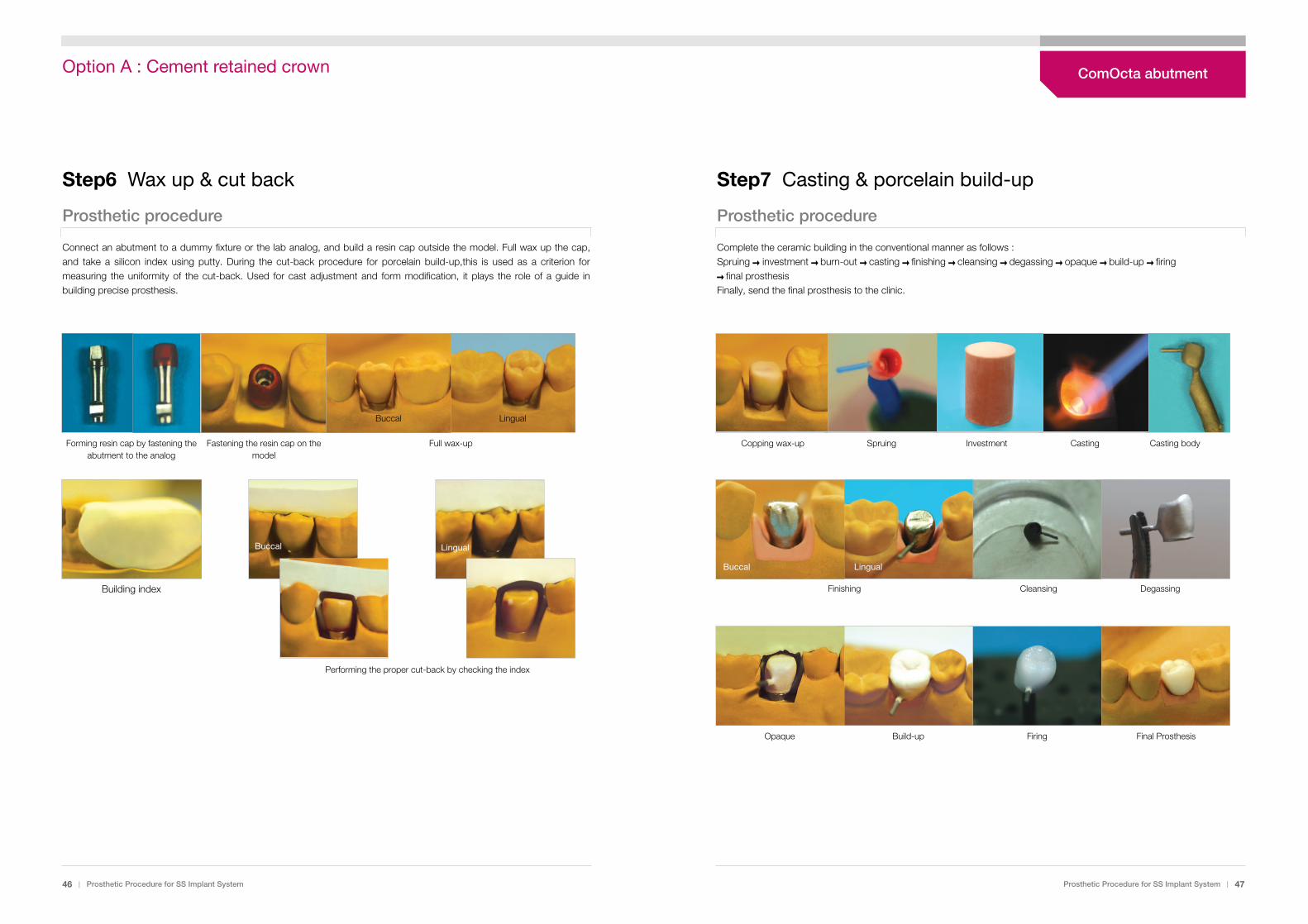
Prosthetic procedure
Complete the ceramic building in the conventional manner as follows : Spruing � investment � burn-out � casting � finishing � cleansing � degassing � opaque � build-up � firing � final prosthesis Finally, send the final prosthesis to the clinic.
Step6 Wax up & cut back
Prosthetic procedure
Connect an abutment to a dummy fixture or the lab analog, and build a resin cap outside the model. Full wax up the cap,and take a silicon index using putty. During the cut-back procedure for porcelain build-up,this is used as a criterion formeasuring the uniformity of the cut-back. Used for cast adjustment and form modification, it plays the role of a guide inbuilding precise prosthesis.
Building index
Performing the proper cut-back by checking the index
46 | Prosthetic Procedure for SS Implant System Prosthetic Procedure for SS Implant System | 47
Forming resin cap by fastening theabutment to the analog
Fastening the resin cap on themodel
Full wax-up
Buccal Lingual
Buccal Lingual
SpruingCopping wax-up Casting Casting bodyInvestment
Opaque Build-up Firing Final Prosthesis
Finishing
Buccal Lingual
Cleansing Degassing
ComOcta abutmentOption A : Cement retained crown
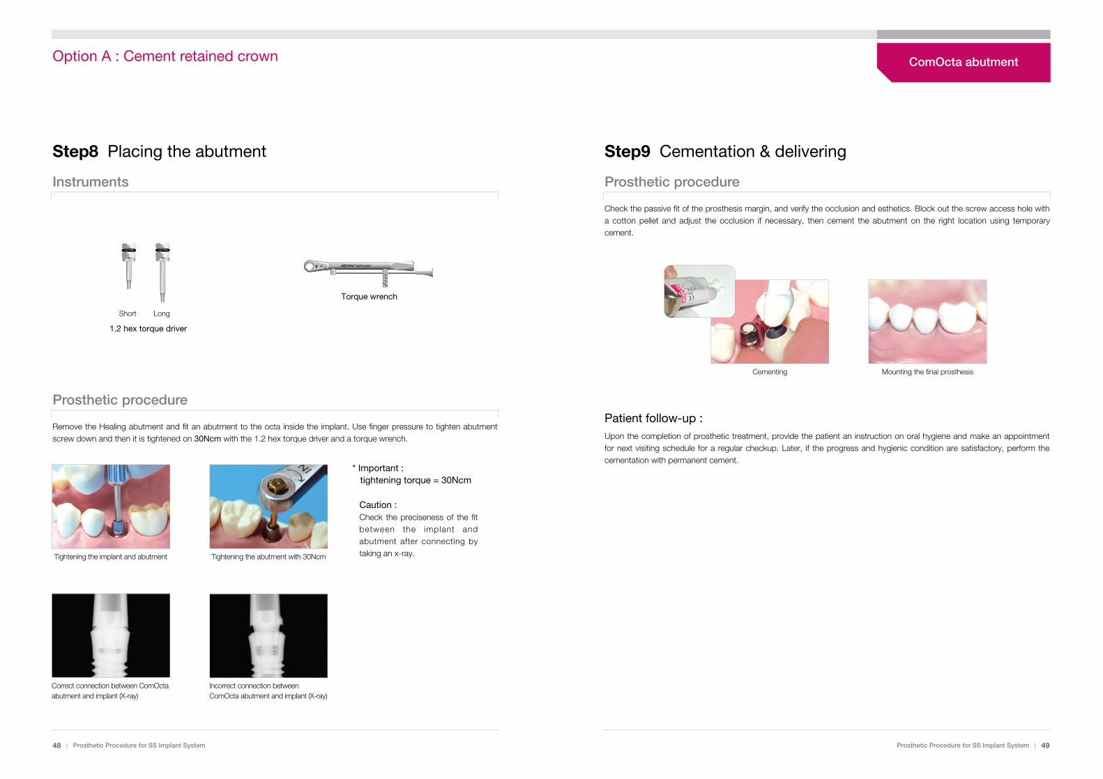
Step9 Cementation & delivering
Prosthetic procedure
Check the passive fit of the prosthesis margin, and verify the occlusion and esthetics. Block out the screw access hole witha cotton pellet and adjust the occlusion if necessary, then cement the abutment on the right location using temporarycement.
Patient follow-up :Upon the completion of prosthetic treatment, provide the patient an instruction on oral hygiene and make an appointmentfor next visiting schedule for a regular checkup. Later, if the progress and hygienic condition are satisfactory, perform thecementation with permanent cement.
Cementing Mounting the final prosthesis
Step8 Placing the abutment
Instruments
Prosthetic procedure
Remove the Healing abutment and fit an abutment to the octa inside the implant. Use finger pressure to tighten abutmentscrew down and then it is tightened on 30Ncm with the 1.2 hex torque driver and a torque wrench.
Tightening the implant and abutment Tightening the abutment with 30Ncm
Correct connection between ComOcta abutment and implant (X-ray)
Incorrect connection between ComOcta abutment and implant (X-ray)
Caution :Check the preciseness of the fitbetween the implant andabutment after connecting bytaking an x-ray.
* Important :tightening torque = 30Ncm
48 | Prosthetic Procedure for SS Implant System Prosthetic Procedure for SS Implant System | 49
Torque wrench
Short Long
1.2 hex torque driver
ComOcta abutmentOption A : Cement retained crown

Step7 Cementation & delivering
Prosthetic procedure
Remove the Healing abutment and fit an abutment to the octa inside the implant. Use finger pressure to tightenabutment screw down and then it is tightened on 30Ncm with the 1.2 hex torque driver and a Torque wrench.
Caution :Check the preciseness of the fitbetween the implant andabutment after connecting bytaking an X-ray.
* Important : Tightening torque = 30Ncm
After adjusting the occlusion, perform the cementation and complete the procedure of forming an occlusal surface insidethe oral cavity using resin to address the esthetic problem caused by the occlusal surface hole.
Patient follow-up :Upon the completion of prosthetic treatment, provide the patient an instruction on oral hygiene and make an appointmentfor next visiting schedule for a regular checkup. Later, if the progress and hygienic condition are satisfactory, perform thecementation with permanent cement.
Connecting the implant and abutment Tightening the abutment with 30Ncm
Cementing Mounting the final prosthesis Forming an occlusal surface with resin
Step6 From wax up to porcelain build-up
Prosthetic procedure
When performing the wax-up procedure, form an access hole for a screw type on the occlusal surface.The following steps are carried out in the same way as in the option A: cement retained crown procedures
Note :Combination retained prosthesisAs a form of maintaining prosthesis by combining the cement-retained typeand the screw-retained type, this prosthesis building method enhancesfunction and convenience of prosthesis by addressing the retrievabilityproblem of the cemented type.
Wax-up Cut-back Spruing Casting Casting body
Build-up Glazing Final prosthesis
50 | Prosthetic Procedure for SS Implant System Prosthetic Procedure for SS Implant System | 51
ComOcta abutmentOption A : Cement retained crown