s.s. yu et al- hif driver point designs
TRANSCRIPT

8/3/2019 S.S. Yu et al- HIF Driver Point Designs
http://slidepdf.com/reader/full/ss-yu-et-al-hif-driver-point-designs 1/30
The Heavy Ion Fusion Virtual National Laboratory
HIF Driver Point DesignsS.S. Yu, 1 R.P. Abbott, 2 R.O. Bangerter, 1 J.J. Barnard, 2 R.J. Briggs, 3 T. Brown, 4 D. Callahan, 2
C.M. Celata, 1 R. Davidson, 4 C.S. Debonnel, 1 A. Faltens, 1 A. Friedman, 2 D.P. Grote, 2
E. Henestroza, 1 I. Kaganovich, 4 J.W. Kwan, 1 P. Heitzenroeder, 4 J.F. Latkowski, 2 E.P. Lee, 1
M. Leitner, 1 B.G. Logan, 1 S.M. Lund, 2 W. Meier, 2 P.F. Peterson, 5 D. Rose, 6 G-L. Sabbi, 1
P.A. Seidl, 1 W.M. Sharp, 2 D.R. Welch 6
Presented at the HIF2004
PPPL
June 7-11, 2004
Princeton, New Jersey
1 Lawrence Berkeley National Laboratory, 2 Lawrence Livermore National Laboratory, 3
Science Applications International Corporation, 4 Princeton Plasma Physics Laboratory,5 University of California, Berkeley, 6 Mission Research Corporation
8/3/2019 S.S. Yu et al- HIF Driver Point Designs
http://slidepdf.com/reader/full/ss-yu-et-al-hif-driver-point-designs 2/30
The Heavy Ion Fusion Virtual National Laboratory
Summary
• An HIF driver point design must be an integratedsystem that is self-consistent from injector totarget
• The Robust Point Design (RPD) is an integratedsystem based on a single accelerator with multiplebeams
• Ongoing Modular Point Design (MPD) studyseeks a self-consistent integrated solution basedon 10-20 accelerator modules with singlebeam/module

8/3/2019 S.S. Yu et al- HIF Driver Point Designs
http://slidepdf.com/reader/full/ss-yu-et-al-hif-driver-point-designs 3/30
The Heavy Ion Fusion Virtual National Laboratory
A Robust Point Design study established a baseline for a multiple-beam quadrupole induction linac HIF driver
MultipleIon
Source/Injectors
Multiple-beam acceleration Drift compression
Bending Finalfocusing
Chamber
transportTargetInput7 MJ
Yield400 MJ
1.6 MeV0.63 A/beam30 µ s120 beams
4 GeV Bi +1
94 A/beam200 ns
4 GeV1.9 kA/beam9.3 ns
Relative beam bunch length at end of: injectionacceleration
drift compression
Common
Induction cores
3 km 400 m

8/3/2019 S.S. Yu et al- HIF Driver Point Designs
http://slidepdf.com/reader/full/ss-yu-et-al-hif-driver-point-designs 4/30
The Heavy Ion Fusion Virtual National Laboratory
Integration of target, chamber, and accelerator requirements led to the self-consistent point design
900170034002000
Focus Magnet Shielding Structure Flinabe LiquidJet Grid
PocketVoid
500 2900
CLTarget
Schematic Liquid Jet Geometry
Neutralizing PlasmaInjectionLiquid Vortex
Extraction
>2000
Liquid VortexInjection
Bare Tube Flinabe Vortex(<400°C)
Plasma/Mag. Shut. (600 - 650°C)
Target Injection
Ion: Bi+
(A=209)Main pulse: 4 GeVFoot pulse: 3.3 GeV120 beams total (72 main,48 foot)Pulse energy: 7 MJFinal spot radius: 2.2 mm
3 D neutronics calculations
Chamber dynamics
Mechanical engineering
Final beam optics
+ target physics +chamber propagationLength: 2.7 km; Efficiency 28%
Total cost: 2.8 B$

8/3/2019 S.S. Yu et al- HIF Driver Point Designs
http://slidepdf.com/reader/full/ss-yu-et-al-hif-driver-point-designs 5/30
The Heavy Ion Fusion Virtual National Laboratory
Target design is a variation of thedistributed radiator target (DRT)

8/3/2019 S.S. Yu et al- HIF Driver Point Designs
http://slidepdf.com/reader/full/ss-yu-et-al-hif-driver-point-designs 6/30
The Heavy Ion Fusion Virtual National Laboratory
A building block pulse shape is used

8/3/2019 S.S. Yu et al- HIF Driver Point Designs
http://slidepdf.com/reader/full/ss-yu-et-al-hif-driver-point-designs 7/30
The Heavy Ion Fusion Virtual National Laboratory
The Robust Point Design (RPD) beam line

8/3/2019 S.S. Yu et al- HIF Driver Point Designs
http://slidepdf.com/reader/full/ss-yu-et-al-hif-driver-point-designs 8/30
The Heavy Ion Fusion Virtual National Laboratory
Neutralization is required for small spot sizes
Results for standard Xe main pulse• time histories of rms radius at selected axial positions• plasma is electrically connected to wall by images and emission
• 2.5 mm waist is close to value needed by distributed-radiator target• Bi is easier to focus and meets spot requirement

8/3/2019 S.S. Yu et al- HIF Driver Point Designs
http://slidepdf.com/reader/full/ss-yu-et-al-hif-driver-point-designs 9/30
The Heavy Ion Fusion Virtual National Laboratory
Beam envelop in final focus region
x- and y- envelopes for the Block E main pulsebeams in the final focus system. The target isto the right.
8/3/2019 S.S. Yu et al- HIF Driver Point Designs
http://slidepdf.com/reader/full/ss-yu-et-al-hif-driver-point-designs 10/30
The Heavy Ion Fusion Virtual National Laboratory
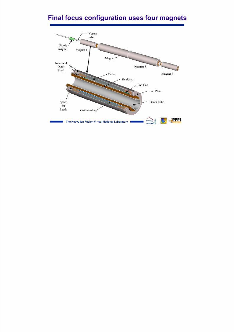
Final focus configuration uses four magnets

8/3/2019 S.S. Yu et al- HIF Driver Point Designs
http://slidepdf.com/reader/full/ss-yu-et-al-hif-driver-point-designs 11/30
The Heavy Ion Fusion Virtual National Laboratory
Magnet lifetimes, which are limited by dose to the insulatorsand neutron fluence to the superconductor, exceed the plant lifetime;Insulator & superconductor lifetimes (in years) are:
– Last magnet: 230/260 – 2nd magnet: 410/1580 – 3rd magnet: 100/610
• Waste disposal ratings aresignificantly reduced fromprevious work: 1.7, 0.5, 0.4 ( 94Nb)
• Increasing liquid stand-off distancein vortices (from 1 5 mm) willreduce lifetimes by ~2x
• Optimizing shielding to increase neutron effectiveness (at cost of gamma-ray shielding effectiveness) should enable all magnets to qualify for disposal as lowlevel waste; adequate margin exists for magnet lifetimeto exceed plant life.
Magnet Lifetime: Sufficient material has been added tomake the shielding & activation results very robust
8/3/2019 S.S. Yu et al- HIF Driver Point Designs
http://slidepdf.com/reader/full/ss-yu-et-al-hif-driver-point-designs 12/30
The Heavy Ion Fusion Virtual National Laboratory
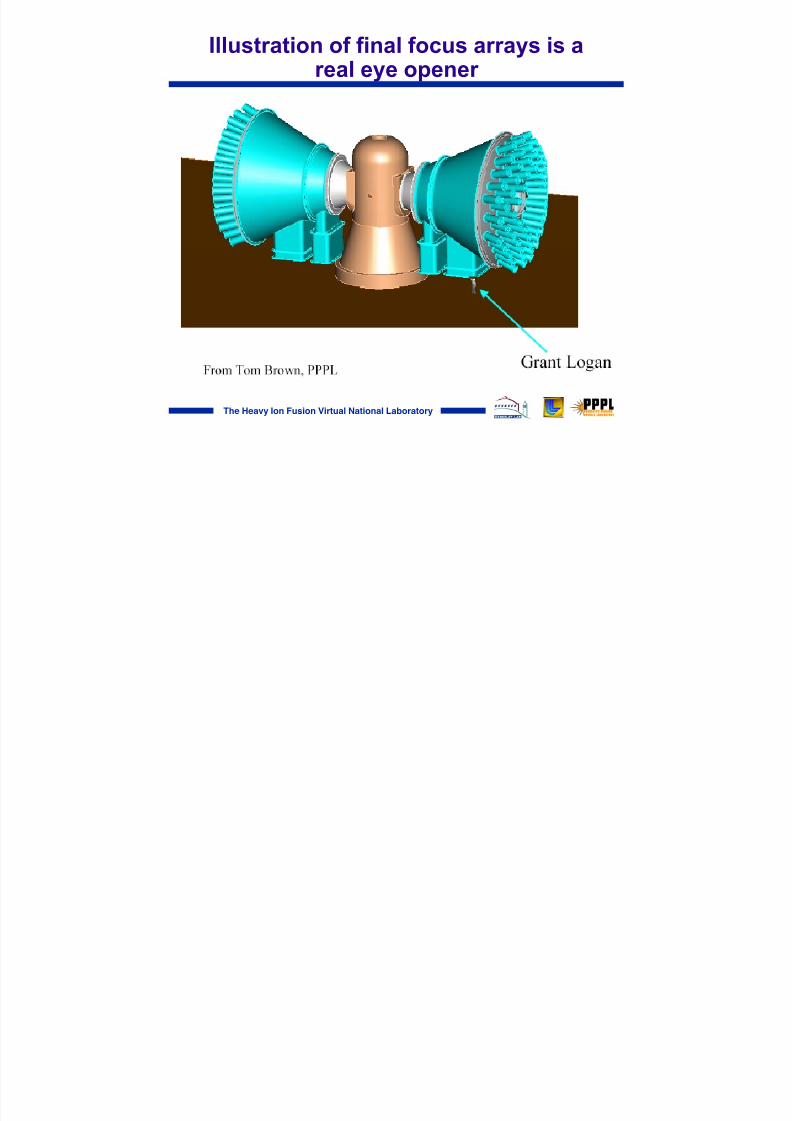
Illustration of final focus arrays is areal eye opener

8/3/2019 S.S. Yu et al- HIF Driver Point Designs
http://slidepdf.com/reader/full/ss-yu-et-al-hif-driver-point-designs 13/30
The Heavy Ion Fusion Virtual National Laboratory
Example of critical physics issue: drift compressionof bunch length by factors of 10 to 30
Perveance
Final FocusDrift compression line
Induction acceleration is mostefficient at τ pulse ~100 to 300 ns Target capsule
implosion timesrequire beam drive
pulses ~ 10 nsBunch tail has a few percent higher
velocity than the head to allowcompression in a drift line
Issues that need more study and experiments:1. Matching beam focusing and space-charge forces during compression.
2. Beam heating due to compression (conservation of longitudinal invariant)
3. Chromatic focus aberrations due to velocity spread
The beam must be confined radially and compressed longitudinally against its space-charge forces

8/3/2019 S.S. Yu et al- HIF Driver Point Designs
http://slidepdf.com/reader/full/ss-yu-et-al-hif-driver-point-designs 14/30
The Heavy Ion Fusion Virtual National Laboratory
Modular Point Design Example: A 16 module,1 beam/module solenoid focus option 1
Pulse energy ~ 6.7 MJV~ 200-300 MV: T~ 2.5 GeV Xe +8 ions or T ~ 200 MeV for Ne +1
High λ injector
Merging beamletsource/injector
or accel/decel
injector
Induction linacsingle beams
r p ~ 15 cmB
s~ 9T
I ~ 6.7 kAT ~ 2.5 GeVΔ t ~ 100 ns
double pulsed for foot and main pulses
Neutralized driftcompressionΔ v/v ~ 0.01
(no space chargestagnation)
1 km 200 m
cusp focusingwith axisymmetric
vortex flow
or
adiabatic plasmalense assisted
pinch with cross- jet flow. liquid
walls
Target
1. B.G. Logan, “A chamber integrated, ....multi-beam, heavy ion power plant ..,” Draft, June 17, 2002 .

8/3/2019 S.S. Yu et al- HIF Driver Point Designs
http://slidepdf.com/reader/full/ss-yu-et-al-hif-driver-point-designs 15/30
The Heavy Ion Fusion Virtual National Laboratory
Solenoids can transport high line chargeddensity at beam low energies
Maximum transportable line charge density has a different scalingthan quadrupoles on key quantities:
λ ≈ 10 µ C m
Β10 T
2
r p
10 cm
2
133
A / q
η
1.0
a / r p
1.0
2
Advantage for large B , r p,Advantage for small A/q (cf. extensive experience with e -
induction linacs)Note λ is independent of energy , so very low
energy transport is possibleFor magnetic quadrupoles,λ ~ (q/A) 1/2β r p , favoring small beams and high energy.
For electric quadrupoles,λ ∼ independent of q/A, r p , and β (except at very low energy when λ ~ β2),
favoring small beams and low (but not too low) ion energy and heavy ions

8/3/2019 S.S. Yu et al- HIF Driver Point Designs
http://slidepdf.com/reader/full/ss-yu-et-al-hif-driver-point-designs 16/30
The Heavy Ion Fusion Virtual National Laboratory
RPD and MPD accelerators have different scalings
Δ Rc =0.47 m
Rci =0.74 m
0.63 V0.63 V ..
s/m coress/m cores
One 120-beam x 3 km
= 3 km total length of linac
16 single-beam modules x 200 m
= 3.2 km total length of linacs
0.4 V0.4 V ..s/ms/mcorescores
Δ Rc =0.3 m
Rci = 0.27 m
7,000 tons of induction cores4000 solenoids
$750 M total capital cost
39,200 tons of
induction cores220,000 quadrupoles
$2.8 B total capitalcost
8/3/2019 S.S. Yu et al- HIF Driver Point Designs
http://slidepdf.com/reader/full/ss-yu-et-al-hif-driver-point-designs 17/30
The Heavy Ion Fusion Virtual National Laboratory
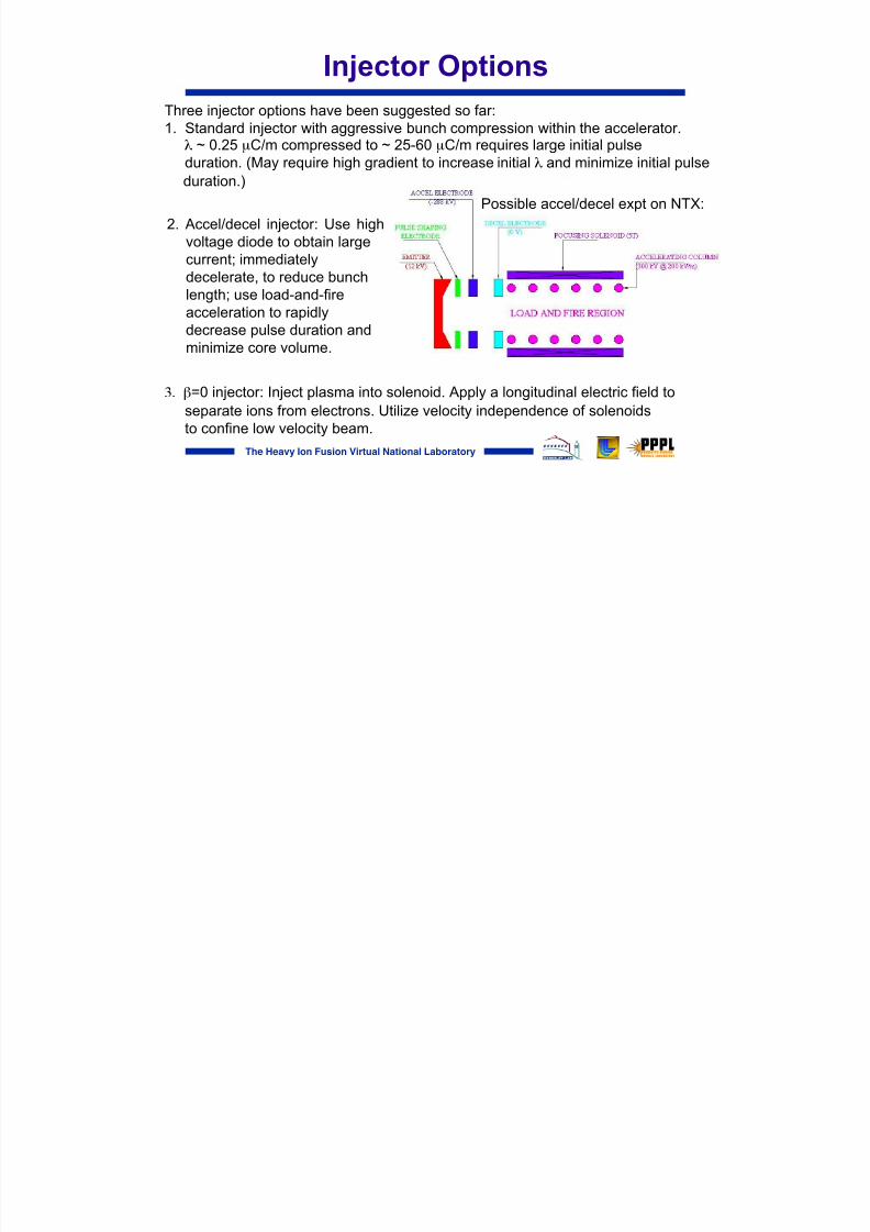
Injector Options
Three injector options have been suggested so far:1. Standard injector with aggressive bunch compression within the accelerator. λ ~ 0.25 µC/m compressed to ~ 25-60 µC/m requires large initial pulse
duration. (May require high gradient to increase initial λ and minimize initial pulseduration.)
3. β=0 injector: Inject plasma into solenoid. Apply a longitudinal electric field toseparate ions from electrons. Utilize velocity independence of solenoidsto confine low velocity beam.
2. Accel/decel injector: Use highvoltage diode to obtain largecurrent; immediatelydecelerate, to reduce bunchlength; use load-and-fireacceleration to rapidlydecrease pulse duration andminimize core volume.
Possible accel/decel expt on NTX:

8/3/2019 S.S. Yu et al- HIF Driver Point Designs
http://slidepdf.com/reader/full/ss-yu-et-al-hif-driver-point-designs 18/30
The Heavy Ion Fusion Virtual National Laboratory
Target will be “hybrid” design, allowinglarger focal spots 1
Hybrid target:Large beam spot
“Hybrid design” for Modular Point Design:
In contrast, Robust Point Design used “Distributed radiator design”Distributed radiator:
"Baseline" target
Spot radius: 1.8 mm x 4.2 mm (main)Pulse energy: 6.5 MJIon range equivalent to 4 GeV Pb (main) and 3.3 GeV (foot)
Spot radius: ~5.0 mm round (or ~5.4 x 3.8 mm elliptical)Pulse energy: 6.7 MJMinimum 8 beams per sideIon range equivalent to 4.5 GeV Pb (main) and
3 GeV Pb (foot)
New task: define the allowable velocity spread that maintainshigh target performance
1. D.A. Callahan, M.C. Herrmann, and M. Tabak, Laser and Particle Beams, 20 , 405 (2002).

8/3/2019 S.S. Yu et al- HIF Driver Point Designs
http://slidepdf.com/reader/full/ss-yu-et-al-hif-driver-point-designs 19/30
The Heavy Ion Fusion Virtual National Laboratory
The drift length for NDC is determined by howmuch velocity tilt the target can accomodate
Δ v1Δ v2
Δ v3
Δ vm
.0319.00481032 m
.0638.0095536 m
.128.0188268 m
.256.037134 m
Δvm /vmΔv1 /v1Driftlength

8/3/2019 S.S. Yu et al- HIF Driver Point Designs
http://slidepdf.com/reader/full/ss-yu-et-al-hif-driver-point-designs 20/30
The Heavy Ion Fusion Virtual National Laboratory
Chamber OptionsVortices with liquid FLiNaBe or FLiBeserving as wall protection, and heatabsorbing fluid, may be well suited for cusp or solenoidal focusing options(upper left).
Hi-life-like chamber protectionsschemes (as in the RPD design, lower right) may be extendable to assistedpinch designs (lower left)

8/3/2019 S.S. Yu et al- HIF Driver Point Designs
http://slidepdf.com/reader/full/ss-yu-et-al-hif-driver-point-designs 21/30
The Heavy Ion Fusion Virtual National Laboratory
A solenoid-based final focus system for a modular driver has attractive features
• Large cone angle θ ~ 100 mr produces a small spot (~ 5 mm) ontarget for ε ~ 4 ×10 -4 m-rad
• Moderate fields allow normal magnets• Highly stripped ions (200-300 MeV Ne +10)• Fringe field aberrations minor
multi-beaminterface
/ fringe fieldsymmetrization R= 2.5 m
final focus solenoid (B ~ 1 T)
0.6 mneutralized drift compression
pulsedsolenoids forchromaticcorrection(B ~ 0.2 T)
80 m
4 m4 m
flibe vortex

8/3/2019 S.S. Yu et al- HIF Driver Point Designs
http://slidepdf.com/reader/full/ss-yu-et-al-hif-driver-point-designs 22/30
The Heavy Ion Fusion Virtual National Laboratory
Self-consistent target / chamber / drift compression: an example
Beam merging in adiabaticlensNearly parallel beamlinesShallow entrance
angle
Anharmonic focusing in Z-
pinch symmetriesFew beam driver Symmetry
Tighter focusing with highQ/M
Insensitive to Z-variation
Driver optimized with high Q/M
Some stripping can occur inNDC
Spot size(~5mm radius)
Independent of Beam current
Can accommodate largeenergy variations
Controlled by initial velicityshaping at entrance to NDCBeam at exit of NDC maintainsinitial velocity tilt
Pulse shapeRange shortening
Hybrid Target Solenoid / NDC Assisted Pinch

8/3/2019 S.S. Yu et al- HIF Driver Point Designs
http://slidepdf.com/reader/full/ss-yu-et-al-hif-driver-point-designs 23/30
The Heavy Ion Fusion Virtual National Laboratory
An integrated PIC Simulation (LSP) from Accelerator Exit to TargetDemonstrates 92% energy deposition within required 5mm spot
50 kA channel current
Bθ
∼100 m
Adiabatic section
Neutralized driftcompression region
Ion beamin Brillouinflow equil.
Hybridtarget
Chamber first wall
XXXXXXXXXXXXXXXXXXXXXXXXX Solenoids
Neutralizedfocusing region
ImmersedPlasma

8/3/2019 S.S. Yu et al- HIF Driver Point Designs
http://slidepdf.com/reader/full/ss-yu-et-al-hif-driver-point-designs 24/30
The RPD and MPD have distinctlydifferent architectures
Vortex chamb
Solenoid in plpinch
Quad focusing / neutralizedballistic transport
Final focus / chamber transport
1 Neutralizedcompressionbeamlines/mo
M vacuum drift compressionbeamlinesDrift Compression
Solenoid/hybr
(1 solenoid/mMultiple quad array for MbeamsTransport
N high λ injeM compact injectorsInjector
Medium (Ne Heavy - Bi (Xe possible)Ion species
N accelerator1 accelerator/1PPSAccelerator/PulsePower System (PPS)
MPD (N modN=10-RPD (M beams M=120)Driver components

8/3/2019 S.S. Yu et al- HIF Driver Point Designs
http://slidepdf.com/reader/full/ss-yu-et-al-hif-driver-point-designs 25/30
The Heavy Ion Fusion Virtual National Laboratory
Summary
• An HIF driver point design must be an integratedsystem that is self-consistent from injector totarget
• The Robust Point Design (RPD) is an integratedsystem based on a single accelerator with multiplebeams
• Ongoing Modular Point Design (MPD) studyseeks a self-consistent integrated solution basedon 10-20 accelerator modules with singlebeam/module

8/3/2019 S.S. Yu et al- HIF Driver Point Designs
http://slidepdf.com/reader/full/ss-yu-et-al-hif-driver-point-designs 26/30
The Heavy Ion Fusion Virtual National Laboratory
BACKUP

8/3/2019 S.S. Yu et al- HIF Driver Point Designs
http://slidepdf.com/reader/full/ss-yu-et-al-hif-driver-point-designs 27/30
The Heavy Ion Fusion Virtual National Laboratory
A 7 MJ induction linac driver using Bi+ isthe baseline
Accelerator parameters at:• Injector • Foot pulse final energy (3.3 GeV)• Main pulse final energy (4.0 GeV)
• Ion = Bi+ (A = 209 amu)• Length = 2.9 km
• Driver efficiency = 38%• Total cost = $2.8B

8/3/2019 S.S. Yu et al- HIF Driver Point Designs
http://slidepdf.com/reader/full/ss-yu-et-al-hif-driver-point-designs 28/30
The Heavy Ion Fusion Virtual National Laboratory
147 J beam energy transport design with 105m drift length
• 3.35-kA, 10-cm, 8-mm-mrad, 231-MeV, 210 ns Ne +1 beam ( 147 kJ ) witha 20% perfect energy tilt to axially focus at L=104.5 m
• Injected Billouin Flow equilibrium into 10 T• Transition to neutralized drift ( σ=10 12 s-1) with .14 T at z = 2.4 m
–n p/nb =10, r L/λ sd ≈ 0.01 << 1 (no self fields)
• 5 kG dipole field at 2.2 m, no plasma electron transport
• Focusing solenoid at 90-100 m (2.7 T)• 50-kA, discharge channel z>101 m: 2-0.5 cm radius in 1.5 m adiabatic
channel; 3-m long, .5-cm radius straight channel
0 5000 1 .104
0
5 .10 4
0.001
Ω i
z i
1000 1750 4500 7250 1 .104
0
10
20
a i
z i
8/3/2019 S.S. Yu et al- HIF Driver Point Designs
http://slidepdf.com/reader/full/ss-yu-et-al-hif-driver-point-designs 29/30
The Heavy Ion Fusion Virtual National Laboratory
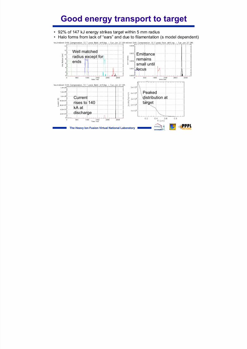
Good energy transport to target
• 92% of 147 kJ energy strikes target within 5 mm radius• Halo forms from lack of “ears” and due to filamentation (s model dependent)
Currentrises to 140kA atdischarge
Emittanceremains
small untilfocus
Peaked
distribution attarget
Well matchedradius except for ends

8/3/2019 S.S. Yu et al- HIF Driver Point Designs
http://slidepdf.com/reader/full/ss-yu-et-al-hif-driver-point-designs 30/30
The Heavy Ion Fusion Virtual National Laboratory
Neutralization of beam space charge in fusionchamber is critical to focusing of driver beams
Plots show 3.2-kA beam of singly charged 2.5-GeV xenon ionsBeam radius vs time is shown at selected points over a 6-m focal length
Without plasma neutralization, the ion kinetic energy would have to triple to recoverthe 2-mm focal spot for the target, increasing the linac voltage, length, and cost